KR920005329B1 - Data precessing system and apparatus therefor - Google Patents
Data precessing system and apparatus thereforDownload PDFInfo
- Publication number
- KR920005329B1 KR920005329B1KR1019890014035AKR890014035AKR920005329B1KR 920005329 B1KR920005329 B1KR 920005329B1KR 1019890014035 AKR1019890014035 AKR 1019890014035AKR 890014035 AKR890014035 AKR 890014035AKR 920005329 B1KR920005329 B1KR 920005329B1
- Authority
- KR
- South Korea
- Prior art keywords
- data
- display
- image data
- memory
- event
- Prior art date
- Legal status (The legal status is an assumption and is not a legal conclusion. Google has not performed a legal analysis and makes no representation as to the accuracy of the status listed.)
- Expired
Links
Images


Classifications
- G—PHYSICS
- G06—COMPUTING OR CALCULATING; COUNTING
- G06F—ELECTRIC DIGITAL DATA PROCESSING
- G06F3/00—Input arrangements for transferring data to be processed into a form capable of being handled by the computer; Output arrangements for transferring data from processing unit to output unit, e.g. interface arrangements
- G06F3/14—Digital output to display device ; Cooperation and interconnection of the display device with other functional units
- G06F3/147—Digital output to display device ; Cooperation and interconnection of the display device with other functional units using display panels
- G—PHYSICS
- G09—EDUCATION; CRYPTOGRAPHY; DISPLAY; ADVERTISING; SEALS
- G09G—ARRANGEMENTS OR CIRCUITS FOR CONTROL OF INDICATING DEVICES USING STATIC MEANS TO PRESENT VARIABLE INFORMATION
- G09G3/00—Control arrangements or circuits, of interest only in connection with visual indicators other than cathode-ray tubes
- G09G3/20—Control arrangements or circuits, of interest only in connection with visual indicators other than cathode-ray tubes for presentation of an assembly of a number of characters, e.g. a page, by composing the assembly by combination of individual elements arranged in a matrix no fixed position being assigned to or needed to be assigned to the individual characters or partial characters
- G09G3/34—Control arrangements or circuits, of interest only in connection with visual indicators other than cathode-ray tubes for presentation of an assembly of a number of characters, e.g. a page, by composing the assembly by combination of individual elements arranged in a matrix no fixed position being assigned to or needed to be assigned to the individual characters or partial characters by control of light from an independent source
- G09G3/36—Control arrangements or circuits, of interest only in connection with visual indicators other than cathode-ray tubes for presentation of an assembly of a number of characters, e.g. a page, by composing the assembly by combination of individual elements arranged in a matrix no fixed position being assigned to or needed to be assigned to the individual characters or partial characters by control of light from an independent source using liquid crystals
- G09G3/3611—Control of matrices with row and column drivers
- G09G3/3622—Control of matrices with row and column drivers using a passive matrix
- G09G3/3629—Control of matrices with row and column drivers using a passive matrix using liquid crystals having memory effects, e.g. ferroelectric liquid crystals
- G—PHYSICS
- G09—EDUCATION; CRYPTOGRAPHY; DISPLAY; ADVERTISING; SEALS
- G09G—ARRANGEMENTS OR CIRCUITS FOR CONTROL OF INDICATING DEVICES USING STATIC MEANS TO PRESENT VARIABLE INFORMATION
- G09G2310/00—Command of the display device
- G09G2310/02—Addressing, scanning or driving the display screen or processing steps related thereto
- G09G2310/0224—Details of interlacing
- G09G2310/0227—Details of interlacing related to multiple interlacing, i.e. involving more fields than just one odd field and one even field
- G—PHYSICS
- G09—EDUCATION; CRYPTOGRAPHY; DISPLAY; ADVERTISING; SEALS
- G09G—ARRANGEMENTS OR CIRCUITS FOR CONTROL OF INDICATING DEVICES USING STATIC MEANS TO PRESENT VARIABLE INFORMATION
- G09G2310/00—Command of the display device
- G09G2310/04—Partial updating of the display screen
- G—PHYSICS
- G09—EDUCATION; CRYPTOGRAPHY; DISPLAY; ADVERTISING; SEALS
- G09G—ARRANGEMENTS OR CIRCUITS FOR CONTROL OF INDICATING DEVICES USING STATIC MEANS TO PRESENT VARIABLE INFORMATION
- G09G2310/00—Command of the display device
- G09G2310/06—Details of flat display driving waveforms
- G—PHYSICS
- G09—EDUCATION; CRYPTOGRAPHY; DISPLAY; ADVERTISING; SEALS
- G09G—ARRANGEMENTS OR CIRCUITS FOR CONTROL OF INDICATING DEVICES USING STATIC MEANS TO PRESENT VARIABLE INFORMATION
- G09G2310/00—Command of the display device
- G09G2310/06—Details of flat display driving waveforms
- G09G2310/061—Details of flat display driving waveforms for resetting or blanking
- G—PHYSICS
- G09—EDUCATION; CRYPTOGRAPHY; DISPLAY; ADVERTISING; SEALS
- G09G—ARRANGEMENTS OR CIRCUITS FOR CONTROL OF INDICATING DEVICES USING STATIC MEANS TO PRESENT VARIABLE INFORMATION
- G09G2310/00—Command of the display device
- G09G2310/06—Details of flat display driving waveforms
- G09G2310/065—Waveforms comprising zero voltage phase or pause
Landscapes
- Engineering & Computer Science (AREA)
- Theoretical Computer Science (AREA)
- Physics & Mathematics (AREA)
- General Physics & Mathematics (AREA)
- Chemical & Material Sciences (AREA)
- Crystallography & Structural Chemistry (AREA)
- Computer Hardware Design (AREA)
- Human Computer Interaction (AREA)
- General Engineering & Computer Science (AREA)
- Liquid Crystal Display Device Control (AREA)
- Control Of Indicators Other Than Cathode Ray Tubes (AREA)
- Radar Systems Or Details Thereof (AREA)
- Facsimiles In General (AREA)
- Hardware Redundancy (AREA)
- Diaphragms For Electromechanical Transducers (AREA)
- Measurement Of Velocity Or Position Using Acoustic Or Ultrasonic Waves (AREA)
- Communication Control (AREA)
- Controls And Circuits For Display Device (AREA)
- Processing Or Creating Images (AREA)
- Control Of El Displays (AREA)
Abstract
Description
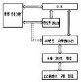
Translated fromKorean제1도는 액정 디스플레이 장치 및 그래픽 컨트롤러의 블록도.1 is a block diagram of a liquid crystal display device and a graphics controller.
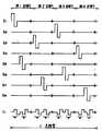
제2도는 액정 디스플레이 장치와 그래픽 컨트롤러간의 이메지 데이타 교신을 위한 타임 코릴레이션(time correlation)을 도시한 타임도.2 is a time diagram showing time correlation for image data communication between a liquid crystal display device and a graphic controller.
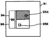
제3도는 다수 그래픽 이벤트(event)를 개략적으로 도시한 표시화면의 설명도.3 is an explanatory diagram of a display screen schematically showing a number of graphical events.
제4도는 본 발명에 사용된 디스플레이 제어 프로그램을 도시한 블록도.4 is a block diagram showing a display control program used in the present invention.
제5도는 본 발명에 사용된 그래픽 컨트롤러의 블록도.5 is a block diagram of a graphics controller used in the present invention.
제6도는 디지탈 인터페이스의 블록도.6 is a block diagram of a digital interface.
제7도는 본 발명에 사용된 디스플레이 구동장치에 대한 인터페이스 타임도.7 is an interface time diagram for a display driving device used in the present invention.
제8도는 FLCD 컨트롤러에 대한 인터페이스 타임도.8 is an interface time diagram for an FLCD controller.
제9a도-9e도, 제16도는 본 발명에 사용된 부분적 재기입을 위한 알고리즘을 도시한 순차도.9A-9E and FIG. 16 are sequential diagrams showing an algorithm for partial rewrite used in the present invention.
제9f도, 9j도 및 9i도는 VRAM에서 구 및 신 폰트(font)데이타 위치간의 상대적 위치를 설명한 개략도.9F, 9J, and 9I are schematic diagrams illustrating the relative positions between old and new font data positions in the VRAM.
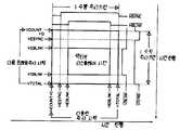
제10도는 본 발명에 사용된 주사 어드레스 데이타 및 디스플레이 데이타를 도시한 개략적 데이타 맵.Fig. 10 is a schematic data map showing scan address data and display data used in the present invention.
제11도는 본 발명이 실시예에 따른 화면의 멀티-윈도우(muti-window)를 설명한 도.11 illustrates a multi-window of a screen according to an embodiment of the present invention.
제12a도-12d도 및 13a도-13c도는 본 발명에 사용된 구동 신호파를 각각 도시한 도면.12A-12D and 13A-13C show driving signal waves used in the present invention, respectively.
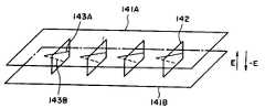
제14도는 강유전성 액정장치의 동작원리를 설명하기 위한 개략적 사시도.14 is a schematic perspective view for explaining the operation principle of the ferroelectric liquid crystal device.
제15a도는 본 발명에 사용된 강유전성 액정장치의 개략적 평면도, 제15b도는 그 안의 선(A-A)을 따라 절단된 단면도.FIG. 15A is a schematic plan view of a ferroelectric liquid crystal device used in the present invention, and FIG. 15B is a cross-sectional view cut along a line A-A therein.
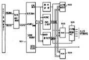
제17도는 본 발명에 사용된 그래픽 컨트롤러의 상세한 블록도.17 is a detailed block diagram of a graphics controller used in the present invention.
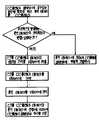
제18도는 전영역 리프레시(refresh) 구동 및 부분적 재기입 주사 구동을 위한 동작 루틴을 도시한 흐름도.18 is a flowchart showing an operation routine for full area refresh driving and partial rewrite scanning driving.
제19도는 부분적 재기입 주사 구동을 위한 동작 루틴을 도시한 흐름도.19 is a flowchart showing an operation routine for a partial rewrite scan drive.
제20도는 1프레임 주사 구동을 도시한 흐름도.20 is a flowchart showing one frame scan drive.
제21도는 부분적 재기입 루틴을 도시한 흐름도.21 is a flowchart showing a partial rewrite routine.
제22도는 전영역 리프레시 구동 루틴이다.22 is a full region refresh drive routine.
제23a도는 부분적 재기입 주사를 위한 주사전극수<전체 화면 주사전극수인 경우의 타임도.FIG. 23A is a time diagram when the number of scanning electrodes for partial rewrite scanning is the number of full screen scanning electrodes. FIG.
제23b도는 부분적 재기입 주사를 위한 주사전극수
제24도는 본 발명에 사용된 디스플레이 이메지예의 도시도.24 is a diagram showing a display image used in the present invention.
본 발명은 데이타 처리시스템 및 장치, 특히 커서 또는 마우스 등의 포인팅 장치를 사용하여 화면을 이동하기에 적합하여 메모리 특성을 갖는 강유전성 액정을 사용한 데이타 처리시스템 및 장치에 관한 것이다.The present invention relates to a data processing system and apparatus, and more particularly, to a data processing system and apparatus using a ferroelectric liquid crystal having memory characteristics, which is suitable for moving a screen using a pointing device such as a cursor or a mouse.
이에 관하여 컴퓨터 터미널 표시장치로서 리프레시 주사형 CRT가 일반적으로 사용되어 왔으며, 메모리 특성을 갖는 벡터주사형 CRT가 CAD를 위하여 대형 고해상도 디스플레이로서 부분적으로 사용된다.In this regard, a refresh scan type CRT has been generally used as a computer terminal display, and a vector scan type CRT having memory characteristics is partially used as a large high resolution display for CAD.
벡터 주사형 CRT에 대하여 한번 디스플레이된 이메지는 다음 스크린 리플레시가 실행될 때까지 리프세시되지 않는다. 이러한 이유로, 이것은 이동 커서 디스플레이, 마우스 등의 포인팅 장치등에 의하여 이동하는 아이콘 디스플레이 및 문자 또는 문장의 편집 디스플레이(삽입, 삭제, 이동, 복사등)등의 리얼타입 맨-머신(man-machine) 인터페이스 디스플레이에 대한 디스플레이 장치로서 적합하지 않다.Images displayed once for a vector scan CRT are not refreshed until the next screen refresh is performed. For this reason, it is a real type man-machine interface display such as a moving cursor display, an icon display moving by a pointing device such as a mouse, and an editing display of characters or sentences (insertion, deletion, movement, copying, etc.). Not suitable as a display device for.
한편 리프레시 주사형 CRT는 스크린 상에 플리커를 방지하기 이하여 60Hz이상의 프레임 주파수를 갖는 리프레시 사이클을 요구하며, 비인터레이스(non-interlaced) 주사 스킴(scheme)이 아이콘의 이동 디스플레이 등의 화면상 데이타의 이동 디스플레이의 양호한 관찰을 가능하게 하기 위하여 채용된다.(TV 세트는 영화 디스플레이의 관점에서 60Hz의 피일드 주파수와 30Hz의 프레임 주파수를 가지며 구동 제어시스템에 적합한 인터페이스 주사 스킴을 채용한다). 따라서 디스플레이 해상도가 높을 수록 디스플레이 장치는 더 크게 되어 고전력, 대형의 구동제어장치와 고가로 된다.On the other hand, the refresh scan type CRT requires a refresh cycle having a frame frequency of 60 Hz or higher in order to prevent flicker on the screen, and a non-interlaced scanning scheme is used to display on-screen data such as moving of icons. It is employed to enable good observation of the mobile display. (The TV set has a feed frequency of 60 Hz and a frame frequency of 30 Hz from the point of view of the movie display and adopts an interface scanning scheme suitable for the drive control system). Therefore, the higher the display resolution, the larger the display device becomes, and the higher the power and large drive control device is.
이러한 대형, 고전력 CRT는 불편하여, 최근 플래트(fla 디스플레이 패널이 개발되고 있다.Such large, high-power CRTs are inconvenient, and a pla display panel has recently been developed.
현재 트위스트 네마틱(twisted nematic) 액정(STN)을 사용하는 고 멀티플렉스 구동시스템, 흑백 디스플레이를 위하여 변형된 시스템 및 플라스마 디스플레이 시스템 등 플래트 디스플레이 패널의 각종 시스템이 있으며, 이들 모두는 CRT시스템과 동일한 이메지 데이타 전송스킴과 화면과 스크린 리프레싱을 위하여 60Hz 이상의 프레임 주파수를 갖는 비인터레이스 주사 스킴을 채용하여 1화면을 구성하기 위하여 400-480라인 차수로 다수이 총 주사선을 사용하고 1000이상의 주사선을 갖는 대형 플래트 디스플레이 패널을 제공하지 않도록 한다.Currently there are various systems of flat display panels, such as high multiplex drive systems using twisted nematic liquid crystal (STN), modified systems for monochrome display, and plasma display systems, all of which are the same image as CRT systems. A large flat display panel with a total number of scan lines and more than 1000 scan lines in the order of 400-480 lines to form one screen by adopting a non-interlaced scanning scheme having a frame frequency of 60 Hz or higher for data transmission scheme and screen and screen refreshing. Do not provide
이것은 이들 디스플레이 패널이 그의 구동원리에 기한 메모리 특성을 가지지 않아 플리커를 방지하기 위하여 60Hz 이상의 프레임 주파수를 가지는 리프레시 사이클을 요구하기 때문이다. 더욱이, 이것은 10-50㎲ 이하의 단기 1수평주사 시간을 초래하여 양호한 콘트라스트를 제공할 수 없다.This is because these display panels do not have memory characteristics based on their driving principle and require a refresh cycle having a frame frequency of 60 Hz or more in order to prevent flicker. Moreover, this results in a short 1 horizontal scanning time of 10-50 Hz or less and cannot provide good contrast.
강유전성 액정장치는 상기 디스플레이 장치를 현격히 능가하는 대형 고해상도 디스플레이를 제공할 수 있으나 그의 낮은 프레임 주파수 구동때문에 맨-머신 디스플레이 장치를 제공하기 위하여 메모리 특성을 이용한(재기입 영역만으로 구성된 주사선을 주사하는 주사 상태로) 부분적 재기입 주사스킴을 필요로 한다.A ferroelectric liquid crystal device can provide a large high-resolution display that surpasses the display device, but because of its low frame frequency drive, a scanning state that uses a memory characteristic (scanning scan lines composed only of rewrite areas) to provide a man-machine display device. A partial rewrite injection scheme is required.
부분적 재기입 주사 스킴은 예컨대 미국특허번호 제4,655,561호에 개시되었다.Partial rewrite injection schemes are disclosed, for example, in US Pat. No. 4,655,561.
부분적 재기입 주사 스킴은 커서 또는 마우스에 의하여 이동하는 디스플레이 및 강유전성 액정 디스플레이 장치에서 스크롤(scrolling) 디스플레이에 특히 적합하다. 그러나 그 상위한 영역의 부분적 재기입 주사를 동시에 실행하는 것이 불가능하므로 부분적 재기입 주사가 부분적 재기입 주사를 위한 스타트 어드레스 및 피니시(finish) 어드레스를 지정함으로써 실행되는 시스템의 경우에 멀티 윈도우의 스크롤 디스플레이중에 마우스 또는 커서의 이동 디스플레이를 실행하는 것이 불가능하다.Partial rewrite scanning schemes are particularly suitable for scrolling displays in displays and ferroelectric liquid crystal display devices that are moved by a cursor or mouse. However, since it is impossible to perform partial rewrite scanning of the upper region at the same time, scroll display of multiple windows in the case of a system where partial rewrite scanning is performed by specifying a start address and a finish address for the partial rewrite scan is performed. It is not possible to carry out the movement display of the mouse or the cursor during the operation.
예컨대 윈도우의 스크롤 디스플레이 및 포인팅 장치의 디스플레이가 관련될 때 동작을 고려하면 먼저 윈도우 디스플레이의 부분적 재기입 주사는 디스플레이 패널상에 부분적 재기입 주사를 시작하기 위하여 요구되며, 그 후에 포인팅 장치가 이동될지라도 포인팅자치를 위한 재기입주사는 윈도우 동작을 위한 주사를 최종 주사선 어드레스까지 완료할 때까지 스타트할 수 없다. 결과적으로 디스플레이상의 포인팅 장치의 이동은 윈도우의 크기(부분적으로 재기입 주사선)에 따라 불연속적이며 어설프게 된다.Considering the operation when the scroll display of a window and the display of a pointing device are involved, for example, first a partial rewrite scan of the window display is required to start a partial rewrite scan on the display panel, even after the pointing device is moved. The rewrite scan for pointing autonomy cannot start until the scan for the window operation has completed until the final scan line address. As a result, the movement of the pointing device on the display is discontinuous and flimsy depending on the size of the window (partially rewritten scan line).
시간당 강유전성 액정 디스플레이 패널의 동작성능에 대하여 언급한다. 형광 스크린상의 퍼시스턴스(persistence)를 이용함으로써 이메지가 형성되는 CRT에 대하여 그의 디스플레이 원리에 기하여 1화면을 형성하기 위하여 필요한 주파수인 충분히 높은 프레임 주파수를 사용하는 것이 필요하다. 요구되는 프레임 주파수는 30Hz 이상이다. 프레임 주파수는 주사선수와 각 주사선을 주사하기 위한 수평주사시간의 적의 역수로 표시된다.The operation performance of the ferroelectric liquid crystal display panel per hour is described. It is necessary to use a sufficiently high frame frequency, which is the frequency necessary for forming a single screen based on its display principle, for the CRT in which the image is formed by using the persistence on the fluorescent screen. The required frame frequency is 30 Hz or more. The frame frequency is expressed as the reciprocal of the target of the scan and the horizontal scan time for scanning each scan line.
현재 알려진 주사처리 또는 모드는 인터레이스 주사처리(1 또는 그 이상의 선을 띄워서)와 비인터레이스 주사처리(띠움없이)를 포함한다. 다른 주사처리로서 쌍(pairing)처리와 스크린의 분할된 부분을 병렬로 동시에 주사하는 처리가 포함되며 후자의 처리는 LCD에 국한된다. NTSC 스탠터드 시스템은 2피일드/프레임과 30Hz의 프레임 주파수로 구성되며 수평주사시간이 약 63.5㎲이고 주사선수가 약 480(효율적 디스플레이 영역을 구성하기 위하여)인 인터레이스 프레임 주사처리법을 채용하고 있다. TN형 LCN는 200-400 주사선과 30Hz 이상의 프레임 주파수를 포함하는 비인터레이스 시스템을 일반적으로 채용하고 있다. 더욱이 CRT에 대하여 40-60Hz의 프레임 주파수와 200-1000 주사선을 사용하는 비인터레이스 주사시스템이 채용된다.Currently known scanning processes or modes include interlaced scanning (with one or more lines floating) and noninterlaced scanning (without strips). Other scanning processes include a pairing process and a process of simultaneously scanning the divided portions of the screen in parallel, and the latter process is limited to the LCD. The NTSC standard system consists of 2 feeds / frame and a frame frequency of 30Hz, and employs an interlaced frame scanning method with a horizontal scan time of about 63.5 kHz and a scan player of about 480 (to form an efficient display area). TN type LCNs typically employ non-interlaced systems containing 200-400 scan lines and frame frequencies above 30 Hz. Furthermore, a noninterlaced scanning system employing a frame frequency of 40-60 Hz and 200-1000 scan lines is employed for the CRT.
1920(주사선수)×2560픽셀로 구성되는 CRT 또는 TN형 LCD를 구동한다고 가정한다. 30Hz의 프레임 주파수를 사용하는 인터레이스 시스템의 경우에 수평주사시간은 약 17.5㎲이며, 수평 도트 클록주파수는 약 147MHz이다(CRT에 대하여 수평 플라이백을 고려하지 않음). CRT의 경우에 147MHz의 수평도트클록 주파수는 현재 이용되는 수상관에 사용되는 비임건의 최대전자비임 변조주파수를 훨신 초과하는 매우 높은 비임주사속도를 초래하여 정확한 이메지 형성이 17.5㎲로 주사함에 의해서도 실행될 수 없다. TN형 LCD의 경우에 1920 주사선의 구동은 현재 이용되는 1/400의 최소 듀티 팩터(duty factor)보다 훨씬 낮은 1/1920의 듀티 팩터에 대응하여 디스플레이가 실패한다. 한편 실제 수평 주사 시간에서의 구동을 고려하면 프레임 주파수는 30Hz 이하로 되어 주사상태가 관찰되고 플리킹이 일어나 디스플레이 질을 현저히 손상시킨다.Assume that you are driving a CRT or TN type LCD consisting of 1920 (scanner) x 2560 pixels. For an interlaced system using a frame frequency of 30 Hz, the horizontal scan time is about 17.5 kHz and the horizontal dot clock frequency is about 147 MHz (no horizontal flyback is considered for the CRT). In the case of CRTs, the horizontal dot clock frequency of 147 MHz results in a very high beam scanning rate far exceeding the maximum electron beam modulation frequency of the beam beam used in current water tubes, so that accurate image formation can be achieved by scanning at 17.5 kHz. none. In the case of a TN-type LCD, the driving of the 1920 scan line fails to correspond to a 1/1920 duty factor which is much lower than the minimum duty factor of 1/400 currently used. On the other hand, considering driving at the actual horizontal scanning time, the frame frequency is 30 Hz or less, so that the scanning state is observed and flickering, which significantly impairs the display quality.
이와 같은 방법에서 CRT와 TN형 LCD에 대한 화면의 확대 및 축소는 주사선수가 디스플레이 원리와 구동소자에 의해 제한되기 때문에 충분히 증가할 수 없으므로 훨씬 제한된다.In this way, the enlargement and reduction of the screen for the CRT and TN type LCDs is much more limited because the scan player cannot increase sufficiently because of the limitations of the display principle and driving elements.
한편 최근에 클라크와 라게웰은 고속응답특성과 메모리 특성(쌍안정성)을 갖는 강유전성 액정장치를 제안했다. 강유전성 액정장치는 특정온도범위에 쉬랄 스메틱(chiral smectic) C상(SmS*) 또는 H상(SmH*)를 나타내며, 이 상태에서 쌍안정성 즉 제1광안정상태 또는 제2광안전상태중 어느 하나를 인가된 전계에 따라서 취하며, 인가전계가 없으면 합성상태를 유지하는 특성을 보인다. 더욱이 강유전성 액정장치는 전계변화에 신속히 응답하므로 고속메모리형의 디스플레이 장치로서 광범위하게 사용되리라 예상된다.Recently, Clarke and Ragewell have proposed a ferroelectric liquid crystal device having fast response characteristics and memory characteristics (bi-stable). A ferroelectric liquid crystal device exhibits a chiral smectic C phase (SmS* ) or H phase (SmH* ) over a specific temperature range, in which either bistable, i.e., first or second photosafety states are present. Is taken according to the applied electric field, and the absence of an applied electric field maintains the synthetic state. Moreover, ferroelectric liquid crystal devices are expected to be widely used as display devices of high speed memory type because they respond quickly to electric field changes.
그러나 이러한 강유전성 액정장치가 클라크에 의해 제안된 장치에서와 같이 이상적인 쌍안정성을 나타내는 것은 어려우나 단안정성 특성을 나타내기 쉽다. 클라크는 전단응력을 상대적 이동에 의해 인가하거나 자계를 인가하는 등의 어라인먼트(alignment) 제어법을 사용하여 영구적 쌍안정성을 실현하고 있다. 그러나 제조기법이란 관점에서 루빙(rubbing) 또는 기판으로의 경사증착법 등 단축지향 처리법을 적용하는 것이 유리하다.However, it is difficult for such a ferroelectric liquid crystal device to exhibit ideal bistable stability as in the device proposed by Clark, but it is easy to exhibit monostable characteristics. Clark realizes permanent bistable stability by using alignment control methods such as applying shear stress by relative movement or by applying magnetic fields. However, from the viewpoint of manufacturing technique, it is advantageous to apply a uniaxially oriented treatment method such as rubbing or gradient deposition to a substrate.
어라인먼트 제어를 위한 기판에 인가하는 이러한 단축 지향처리 가끔 영구적 쌍안정성을 제공하는데 실패하고 있다. 즉 소위 단안정 어라인먼트 상태를 제공하며, 전계가 인가된 상태에서 형성된 쌍축 지향상태는 수 ms에서 수시간에 거친 기간에서 전계가 인가되지 않은 상태로 단축 지향상태로 변하는 경향이 있다. 이런 이유로 단안정성을 보이는 강유전성 액정등을 사용한 디스플레이 장치는 전계의 인가하에 형성된 이메지가 전계의 제거에 따라 상실된다는 문제가 있다. 특히 멀티플렉싱 구동에서 비어드레스된 주사선상의 픽셀에서 기입상태는 점점 상실된다는 문제점이 관찰되었다. 이러한 문제를 해결하기 위하여 선택된 주사선상의 픽셀이 "혹"을 제공하기 위한 전압 또는 "백"을 전공하기 위한 전압이 선택적으로 공급되는 구동스킴(구동스킴을 리프레시함)이 제공되며, 주사선은 1프레임 또는 1피일드의 사이클에서 순차 선택되며, 이 사이클의 기입을 위해 반복된다. 이러한 리프레시 구동스킴은 투과율상의 변동을 거의 제공하지 않으며, 기입주사선의 시각인식(나머지선 보다 더 높은 광도가 쉽게 인식되는 경우) 및 30Hz 미만의 프레임 주파수 하에서 플리킹의 발생등의 난점이 제거된다. 우리의 연구에 따라 유사한 효과가 약 5Hz와 동일한 저 주파수하에서도 확인이 되었다. 상기 사실은 30Hz의 프레임 주파수가 구동을 위하여 요구한다는 CRT 및 TN형 LCD의 상기 요건으로부터 일어나는 화면이 확대 및 축소에 대한 문제를 동시에 해결한다.Such unidirectional processing applied to a substrate for alignment control has sometimes failed to provide permanent bistable. In other words, it provides a so-called monostable alignment state, and the biaxially oriented state formed in the state where the electric field is applied tends to change to the uniaxially oriented state without the electric field applied in the period of several ms to several hours. For this reason, a display device using a ferroelectric liquid crystal lamp having monostability has a problem in that an image formed under application of an electric field is lost as the electric field is removed. In particular, a problem has been observed that in the multiplexing driving, the write state is gradually lost in pixels on the scan line that are baredressed. In order to solve this problem, a driving scheme (refreshing the driving scheme) is provided in which a voltage for providing a "hog" or a voltage for "back" is selectively supplied by a pixel on a selected scanning line, and the scanning line is one frame. Or one cycle of one cycle, and is repeated for the writing of this cycle. Such a refresh drive scheme provides little variation in transmittance, and eliminates difficulties such as visual recognition of write scan lines (when higher luminance is easily recognized than the rest lines) and generation of flickering at frame frequencies below 30 Hz. In our study, a similar effect was observed even at low frequencies equal to about 5 Hz. This fact simultaneously solves the problem of magnification and reduction of the screen resulting from the above requirements of CRT and TN type LCDs that a frame frequency of 30 Hz is required for driving.
그러나 상기와 같은 저주파수 리프레시 구동은 문자편집 또는 그래픽 디스플레이상의 스무스 스크롤 또는 커서 이동등의 소위 영화 디스플레이에 대하여 너무 느려 디스플레이 성능의 악화를 초래한다. 최근에 컴퓨터, 주변기기 및 이를 위한 소프트웨어가 현저히 발전되었다. 예컨태 대형화면과 고밀도 디스플레이를 위하여 다수 화면이 디스플레이 영역상에 중첩되어 디스플레이 되는 멀티 윈도우 디스플레이 스킴이라 하는 표시스킴이 개발되었다. 강유전성 액정장치를 내장한 디스플레이 장치는 CRT 및 TN형 LCD등의 종래 디스플레이 장치에 의해 실현되는 영역을 훨씬 초과하는 화면영역을 확대 및 축소시키는데 효율적인 것이다. 이러한 확대 및 축소에 따라 프레임 주파수를 더 낮게 해아 한다는 문제를 발생하며, 스무스 스크롤 및 커서 이동의 속도가 훨씬 더 낮게 된다.However, such low frequency refresh drive is too slow for so-called movie displays, such as text editing or smooth scrolling or cursor movement on a graphic display, resulting in deterioration of display performance. Recently, computers, peripherals and software for them have developed significantly. For example, a display scheme called a multi-window display scheme in which a plurality of screens are superimposed and displayed on a display area is developed for a large screen and a high density display. Display devices incorporating ferroelectric liquid crystal devices are effective for enlarging and reducing screen areas far beyond those realized by conventional display devices such as CRT and TN type LCDs. This expansion and contraction leads to the problem of lowering the frame frequency, and the speed of smooth scrolling and cursor movement is much lower.
상기와 같이 강유전성 액정 디스플레이 장치는 디스플레이를 위한 이메지 데이타의 변동(스위치)의 원활화를 위하여 필요하다. 표시 화면상의 스위칭의 원활화라는 면에서 비인터레이스 주사가 바람직하며, 본래의 CRT시스템에서 전체표시영역 또는 스크린은 고프레임 주파수가 플리커 방지를 위하여 채택되는 동안 비인터레이스 스킴에 의하여 주사된다.As described above, the ferroelectric liquid crystal display device is required for smoothing the variation (switch) of the image data for display. Noninterlaced scanning is preferable in terms of smooth switching on the display screen, and in the original CRT system, the entire display area or screen is scanned by a noninterlacing scheme while high frame frequency is adopted for flicker prevention.
그러나 저프레임 주파수 구동은 상기와 같이 강유전성 액정 디스플레이 장치에 채택되기 때문에 영상질의 유지(플리커의 방지)라는 면에서 비인터레이스 주사 스킴에 의하여 항상 전체화면을 재기입하는 것은 소망스럽지 않다.However, since the low frame frequency driving is adopted in the ferroelectric liquid crystal display device as described above, it is not desirable to always rewrite the entire screen by the non-interlaced scanning scheme in terms of maintaining image quality (preventing flicker).
특히 강유전성 액정 디스플레이 장치에서 상기 부분적 주사 스킴은 마우스 또는 커서의 이동 디스플레이 또는 멀티 윈도우의 스크롤 디스플레이에 대하여 적합하다. 이러한 이동 디스플레이 및 스크롤 디스플레이의 스무스 디스플레이를 실행하는 것이 요구되지만 양호한 화면의 질을 제공하며 이동 디스플레이 및 스크롤 디스플레이의 원활성을 개선한 만족할만한 시스템이 개발되지 않았다.Particularly, in the ferroelectric liquid crystal display device, the partial scanning scheme is suitable for a moving display of a mouse or a cursor or a scroll display of a multi window. Although it is required to carry out such smooth display of mobile displays and scroll displays, no satisfactory system has been developed that provides good screen quality and improves the smoothness of mobile displays and scroll displays.
본 발명의 목적은 이메지 디스플레이가 강유전성 액정 디스플레이 장치의 맨-머신 인터페이스로서 리얼타임동작성을 유지하기에 적합한 데이타 처리시스템 및 장치를 제공하는 것이다.It is an object of the present invention to provide a data processing system and apparatus in which an image display is suitable for maintaining real-time operability as a man-machine interface of a ferroelectric liquid crystal display device.
본 발명의 다른 목적은 표시화면에서 스크롤 디스플레이 원도우내의 포인팅 장치로부터 디스플레이 폰트의 원활한 고속 디스플레이 이동을 할 수 있는 강유전성 액정 디스플레이 장치를 사용한 데이타 처리시스템을 제공하는 것이다.Another object of the present invention is to provide a data processing system using a ferroelectric liquid crystal display device capable of smooth high-speed display movement of display fonts from a pointing device in a scroll display window on a display screen.
본 발명의 또다른 목적은 30Hz이하의 프레임 주파수로 주사구동하에서 고속 커서 이동 및 마우스 이동할 수 있는 데이타 처리시스템 및 장치를 제공하는 것이다.It is still another object of the present invention to provide a data processing system and apparatus capable of fast cursor movement and mouse movement under scanning driving at a frame frequency of 30 Hz or less.
본 발명의 특징에 따라 (a)다수의 그래픽 이벤트를 가지는 이메지 데이타를 수신하는 수단 ; (b)수신된 이메지 데이타가 그래픽 이벤트의 소정 디스플레이 우선순위 레벨에 따라 그래픽 이벤트의 고 디스플레이 우선순위 레벨부터 차례로 메모리에 기억되도록 이메지 데이타 기억 메모리를 제어하는 수단 ; 및 (c)기억된 이메지 데이타가 제어수단을 구동하도록 그래픽 이벤트의 고 우선순위 레벨로부터 순차로 전송되도록 이메지 데이타 기억 메모리를 제어하는 수단으로 구성되는 데이타 처리장치가 제공된다.According to a feature of the invention (a) means for receiving image data having a plurality of graphical events; (b) means for controlling the image data storage memory such that the received image data is stored in the memory in order from the high display priority level of the graphic event according to the predetermined display priority level of the graphic event; And (c) means for controlling the image data storage memory such that the stored image data is sequentially transmitted from the high priority level of the graphic event so as to drive the control means.
본 발명의 다른 특징에 따라 (a)수신된 이메지 데이타가 이메지 데이타 기억메모리에 기억되도록 이메지 데이타 기억 메모리를 제어하는 수단, (b)이메지 데이타 기억 메모리로 부터 직렬로 수신하고 위하여 주사선을 선택하는 주사선 어드레스 데이타 및 선택된 주사선에 관한 데이타 선에 인가된 디스플레이 데이타 신호를 제어하는 디스플레이 데이타를 구동제어수단에 전송하는 수단, 및 (c)주사선 어드레스 데이타를 기억하는 수단으로 구성되는 데이타 처리장치가 제공된다.According to another feature of the invention, (a) means for controlling the image data storage memory such that the received image data is stored in the image data storage memory, and (b) a scanning line for serially receiving from the image data storage memory and selecting a scan line for serially receiving the image data storage memory. There is provided a data processing apparatus comprising means for transferring display data for controlling address data and display data signals applied to a data line relating to a selected scan line to drive control means, and (c) means for storing scan line address data.
본 발명의 이들 및 다른 특징은 첨부도면을 참고로 하여 본 발명의 실시예의 다음 기술로부터 명백해질 것이다.These and other features of the present invention will become apparent from the following description of embodiments of the invention with reference to the accompanying drawings.
A. 신호전송스킴A. Signal Transmission Scheme
제1도는 강유전성 액정 디스플레이 장치(10)와 디스플레이 데이타 공급원으로서 예컨대 개인용 컴퓨터의 장치 몸체에 제공되는 그래픽 컨트롤러(102)의 구성을 도시한다. 제2도는 이메지 데이타의 교신을 위한 타임도이다.1 shows the configuration of a ferroelectric liquid
디스플레이 패널(103)은 한쌍의 유리판상에 각각 배설되어 있으며, 어라이닝 처리가 되어 있는 1120주사전극 및 1280데이타 전극으로 구성된 매트릭스 전극 구조 및 유리기판 사이에 배설된 강유전성 액정으로 구성되어 있다. 주사 전극 (선) 및 데이타 (선)는 주사선 구동회로(104)와 데이타선 구동회로(105)에 각각 접속된다.The display panel 103 is disposed on a pair of glass plates, respectively, and is composed of a matrix electrode structure composed of an arrayed 1120 scan electrode and a 1280 data electrode, and a ferroelectric liquid crystal disposed between the glass substrates. The scan electrodes (lines) and data (lines) are connected to the scan line driver circuit 104 and the data line driver circuit 105, respectively.
이하에서 도면을 참고하여 동작을 설명한다. 그래픽 컨트롤러(102)는 주사선을 지정하는 주사선 어드레스 데이타와 어드레스 데이타에 의해 지정된 주사선상의 이메지 데이타(PD0-PD3)를 액정 디스플레이 장치의 디스플레이 구동 회로(104/105)(주사선 구동회로(104)와 데이타 구동회로(105)로 구성됨)로 공급한다. 이 실시예에 주사선 어드레스 데이타와 디스플레이 데이타로 구성되는 이메지 데이타는 동일 송신선을 통하여 전송되어 상기 2가지 형의 데이타를 구별하는 것이 필요하다. 이와 같은 구별을 위하여 신호 AH/DL이 사용된다. 고레벨에서의 AH/DL신호는 주사선 어드레스 데이타를 의미하며, 및 저레벨에서의 AH/DL신호는 디스플레이 데이타를 의미한다.The operation will be described below with reference to the drawings. The
액정 디스플레이 장치(101)에서 주사선 어드레스 데이타는 구동제어회로(111)에 의해 전송 이메지 데이타(PD0-PD3)로 부터 취출된 다음에 지정된 주사선을 구동하기 위한 시간과 동기하여 주사선 구동회로(104)에 공급된다. 주사선 어드레스 데이타는 주사선 구동회로(104)에서의 디코더(106)에 입력되며, 디스플레이패널(103)에서의 지정된 주사선은 디코더(106)의 도움하에 주사신호발생신호(107)에 의하여 구동된다.In the liquid
한편, 디스플레이 데이타는 데이타선 구동회로(105) 내의 시프트 레지스터(108)에 도입되며, 전송클록신호에 기하여 4픽셀 데이타의 유닛에 의하여 시프트된다. 1수평 주산선을 위한 디스플레이 데이타의 시프트가 시프트레지스터(108)에 의하여 완료될 때 1280픽셀용 디스플레이 데이타는 병렬로 배설된 선 메모리에 전송되어, 1수평주사의 기간동안 기억되며 데이타 신호발생회로(110)를 통하여 디스플레이 데이타 신호로서 각 데이타선에 공급된다.On the other hand, the display data is introduced into the
더욱이 본 실시예에서 액정 디스플레이 장치(101)에서 디스플레이 패널(103)의 구동은 그래픽 컨트롤러(102) 내의 주사선 어드레스 데이타와 디스플레이 데이타가 동기되지 않으므로 이메지 데이타 전송시점에서 장치(101, 102)를 동기 시키는 것이 필요하다. 신호(SYNC)는 동기화를 실행하며, 1수평주사기간 각각에서 액정 디스플레이 장치(101) 내의 구동제어회로(111)에서 발생된다. 그래픽 컨트롤러(102)는 항상 SYNC신호를 모니터하여 SYNC신호가 저레벨에 있을 때 이메지 데이타를 전송하고, SYNC 신호가 고레벨에 있을때 1수평주사선동안 이메지 데이타의 전송을 완성한 후에는 전송을 실행하지 않는다. 특히, 제2도를 참고로 하여, 그래픽 컨트롤러(102)가 고레벨 AH/DL신호를 즉시 세트하고, SYNC신호가 저레벨에 있음을 검출할 때 1수평주사선동안 이메지 데이타의 전송을 시작한다. 액정 디스플레이 장치(101)내의 구동제어회로(111)는 이메지 데이타 전송기간동안 SYNC신호를 고레벨로 세트한다. 디스플레이 패널(103)에의 기입이 소정의 1수평주사 기간후에 완료되었을 때 구동 컨트롤로 회로(FLCD 컨트롤러) (111)은 다음 주사선을 위하여 이메지 데이타를 수신할 수 있도록 SYNC신호를 저레벨로 복귀시킨다.In addition, in the present embodiment, the driving of the display panel 103 in the liquid
특히, 주사전극과 이메지 데이타를 어드레스하기 위한 주사전극 어드레스 데이타는 4신호선(PD0, PD1, PD2, PD3)을 통하여 그래픽 컨트롤러(102)에서 제어회로(111)로 공급된다. 본 실시예에서, 주사전극 어드레스 데이타(A0, A1, A2, …, A11)와 이메지 데이타(D0, D1, …, D1278, D1279)가 동일 송신선을 통하여 각각 전송되므로 주사전극 어드레스 데이타와 이메지 데이타를 구별하는 것이 필요하다. 본 실시예에서는 판별신호(AH/DL)가 이를 위해 사용된다. 고레벨에 있는 AH/DL신호는 주사 전극 어드레스 데이타를 의미하며, 저레벨에 있는 AH/DL신호는 이메지 데이타를 의미한다.In particular, the scan electrode address data for addressing the scan electrode and the image data is supplied from the
AH/DL신호는 또한 디스플레이 데이타 전송을 위한 전송초기화 신호이기도 하다.The AH / DL signal is also a transmission initialization signal for display data transmission.
주사 전극 어드레스 데이타가 주사 전극 구동회로(107)에 공급되고 이메지 데이타가 데이타 전극구동회로(105)에 공급될 때, 주사전극 어드레스 데이타(A0-A11) 및 이메지 데이타(D0-D1279)는 신호선(PD0-PD3)을 통하여 직렬로 공급된다. 주사 전극 어드레스 데이타(A0-A11) 및 이메지 데이타(D0-D1279)를 분배하거나 주사 전극 어드레스 데이타(A0-A11)를 추출하기 위한 회로를 제공하는 것이 필요하다. 이 동작은 제어회로(111)에 의하여 실행된다. 제어회로(111)는 신호선(PD0-PD3)을 통하여 공급된 주사전극 어드레스 데이타(A0-A11)를 취출하여 이 데이타를 일시 기억하고 지정된 주사전극을 구동하기 위하여 수평주사기간내에 주사전극구동회로(104)로 공급한다. 주사전극 어드레스 데이타(A0-A11)는 주사전극 구동회로(104)내의 디코더(106)에 공급되어 디코더(106)를 통하여 주사 전극(12C)을 선택한다.When the scan electrode address data is supplied to the scan
한편 이메지 데이타(D0-D1279)는 데이타 전극 구동회로(105)내의 시프트 레지스터(108)에 공급되어 데이타 전극(1280 선)에 대응하는 픽셀을 위한 이메지 데이타 (D0-D1279)로 분리되며, 전송클록신호(CLK)에 의하여 4픽셀에 대하여 시프트한다. 1수평 주사선을 위한 데이타의 시프트 동작은 시프트 레지스터(108)에 의해 완성되며, 시프트 레지스터(108) 내의 이메지 데이타(D0-D1279)의 1280 비트는 선메모리(109)에 전송되며 수평주사기간내에 라인 메모리에 기억된다. 더욱이 본 실시예에서, 디스플레이 패널(103)의 구동과 주사전극 어드레스 데이타(A0-A11)및 이메지 데이타(D0-D1279)의 그래픽 컨트롤러(102)에서의 발생이 동기되지 않으므로 제어회로(111) 및 그래픽 컨트롤러(102)를 디스플레이 데이타 전송시점에서 동기화하는 것이 요망된다. 이를 위하여 동기신호(SYNC)가 각 수평주사를 위하여 제어 회로에서 발생된다.On the other hand, the image data D0-D1279 is supplied to the
신호(SYNC)는 신호(AH/DL)와 관련된다. 그래픽 컨트롤러(102)는 항상 신호(SYNC)를 감시하여 신호(SYNC)가 로우인 때 디스플레이 데이타를 전송하고, 신호(SYNC)가 하이인 때 1수평신호를 위한 데이타를 전송한 후에 전송을 실행하지 않는다. 특히, 제2도에서 신호(SYNC)가 로우로 되는 시점에서 AH/DL신호는 점(A)에서 하이로 되고, 다음에 제어회로(111)는 SYNC신호를 디스플레이 데이타 전송기간중에 하이로 된다.Signal SYNC is associated with signal AH / DL. The
다음에 점(A)에서 계산된 1수평주사기간인 점(B)에서 SYNC신호는 로우로 복귀된다. 그래픽 컨트롤러(102)가 디스플레이 데이타를 점(B)에서 연속전송하는 경우 즉 다음 주사전극이 구동되는 경우 AH/DL신호는 다시 하이로 되어 전송을 시작한다. 전체 영역 리프레시 구동 또는 전체 화면(영역)주사구동은 본 실시예에서 실행되어, 구동이 라인순으로 연속실행한다.The SYNC signal then returns low at point B, which is the one horizontal scanning period calculated at point A. When the
상기 1수평주사기간(1주사선택기간에 대응)이 강유전성 액정의 특성과 최적 구동조건을 고려한 구동방식에 의하여 미리 정해진다. 본 실시예에서 1수평 주사기간은 실온에서 약 250㎲로 설정 되어 프레임 주파수는 10Hz이다. 더욱이 전송클록(CLK)주파수는 5MHz이며, 주사전극 어드레스 데이타 및 이메지 데이타의 전송시간은 약 40.8㎲이고, 제2도에 도시된 대기시간은 209.2㎲이다. 제어신호(CNT)는 소망의 구동파형을 발생하기 위한 제어신호이다. 이것은 제어회로(111)에서 각 구동회로(104,105)로 공급된다. CNT출력을 위한 시간은 주사전극 어드레스 데이타(A0-A11)를 제어회로(11)에서 주사전극 구동회로(104)로 출력하기 위한 시간과 동일하며, 또한 시프트 레지스터(108) 내의 이메지 데이타를 라인 메모리(109)로 전송하는 시간과 동일하다.The one horizontal scanning period (corresponding to one scanning selection period) is predetermined by a driving method in consideration of characteristics of the ferroelectric liquid crystal and optimum driving conditions. In this embodiment, one horizontal syringe stem is set at about 250 Hz at room temperature and the frame frequency is 10 Hz. Furthermore, the transmission clock (CLK) frequency is 5 MHz, the transmission time of the scan electrode address data and the image data is about 40.8 ms, and the waiting time shown in FIG. 2 is 209.2 Hz. The control signal CNT is a control signal for generating a desired drive waveform. It is supplied from the control circuit 111 to the respective drive circuits 104 and 105. The time for the CNT output is equal to the time for outputting the scan electrode address data A0-A11 from the
CNT신호를 출력하기 위한 시간은 SYNC신호의 저레벨 출발점(A점)으로부터의 전송시간(40.8㎲)과 이전의 라인에 대한 억세스 출발점에서 부터 계산된 1수평주사기간의 완료 후인 점에서 스위치된다. 본 실시예에서 전송시간의 완료점과 로우로 된 다음 신호의 점(B)사이에 설정된 C기간은 일정하게 결정된다.The time for outputting the CNT signal is switched at the point after the completion of one horizontal scanning period calculated from the transmission time (40.8 ms) from the low level start point (point A) of the SYNC signal and the access start point for the previous line. In this embodiment, the C period set between the completion point of the transmission time and the point B of the next signal to be low is determined constantly.
상기 교신은 구동회로(104,105) 사이에서 또는 그래픽 컨트롤러(102)와 제어회로(111)사이에서 실행되며, 디스플레이패널은 상기 타임 순서에 따라 구동된다.The communication is executed between the drive circuits 104 and 105 or between the
B. 디스플레이 데이타 처리B. Display Data Processing
제3도는 멀티 윈도우와 멀티타스크 시스템에 따른 디스플레이 데이타를 표시하기 위해 발생되는 다수 디스플레이 디만드(demand)에 직면할 때 디스플레이 화면(3)을 도시한다.3 shows a
디스플레이 디만드 31 : 마우스 폰트 또는 커서를 경사방향으로 원활하게 이동하기 의한 것.Display demand 31: Smooth movement of the mouse font or cursor in the oblique direction.
디스플레이 디만드 32 : 액티브 화면 영역으로서 윈도우를 선택하여 후자의 전면에 이미 디스플레이된 윈도우를 오버랩하기 위하여 이를 디스플레이함.Display demand 32: Selects the window as the active screen area and displays it to overlap the window already displayed in front of the latter.
디스플레이 디만드 33 : 키이보드로부터의 입력에 가하여 문자를 삽입하기 위한 것.Display demand 33: For inserting characters in response to input from the keyboard.
디스플레이 디만드 34 : 화살표 방향으로 이미 디스플레이된 문자를 이동.Display demand 34: Moves the already displayed character in the direction of the arrow.
디스플레이 디만드 35 : 중첩영역의 디스플레이를 변경.Display demand 35: Change the display of the overlap area.
디스플레이 디만드 36 : 비액티브 윈도우를 디스플레이함.Display demand 36: Displays inactive windows.
디스플레이 디만드 37 : 비액티브 윈도우의 스크롤 디스플레이를 실행.Display demand 37: Enable scrolling display of inactive windows.
디스플레이 디만드 38 : 전체 영역 주사 디스플레이(또는 리프레시)를 실행.Display demand 38: Performs a full area scan display (or refresh).
다음 표1은 상기 디스플레이 디만드 31-38에 대응하는 그래픽 이벤트의 우선순위를 도시한다.Table 1 below shows the priority of graphic events corresponding to the display demand 31-38.
[표 1]TABLE 1

상기 표에서, "부분적 재기입"은 부분적 재기입 영역내의 주사선만이 주사되는 구동스킴에 조회한다. "멀티-피일드"만 N피일드(N=2, 4, 8 …2N)를 사용한 멀티-인터레이스 주사 모드에 따라 1프레임이 주사되는 1프레임 주사스킴을 의미한다(미국 특허원S.N.271,240호 및 유럽 특허원 No. 88118766.0에 기술되었음).In the table, " partial rewrite " refers to a drive scheme in which only scan lines in the partial rewrite area are scanned. Only "multi-feed" means a one-frame scanning scheme in which one frame is scanned according to a multi-interlaced scanning mode using N-feeds (N = 2, 4, 8 ... 2N ) (US Patent Application Ser. And European Patent Application No. 88118766.0).
"디스플레이 우선순위 레벨"이란 본 실시예에서 맨-머신 인터페이스의 동작성능에 보다 큰 비중을 두기 위하여 미리 정해진다. 따라서, 그래픽 이벤트(31)(마우스 이동 디스플레이)는 최고 우선순위 레벨에 위치하며, 다음에 그래픽 이벤트(33, 34, 37, 38)는 내림차순으로 우선순위가 주어진다. 더욱이 "백 동작"은 그래픽 프로세서에서 내부 백 동작을 의미한다."Display priority level" is predetermined in this embodiment in order to place a greater emphasis on the operational performance of the man-machine interface. Thus, graphic event 31 (mouse movement display) is located at the highest priority level, and then
마우스 이동 디스플레이에 최고 우선순위 레벨이 배당되는 이유는 마우스와 같은 포인팅 장치가 컴퓨터에서 조작자의 의도를 가장 신속하게(리얼 타임 기준에서) 반영하기 때문이다. 다음으로 중요한 그래픽 이벤트는 키이보드로부터의 문자입력이다. 이것은 그의 우선순위가 마우스보다 더 낮도록 버퍼되며, 한편 고 리얼 타임 특성을 요구한다. 키이보드로부터의 입력결과로서 윈도우에서의 화면 리프레시는 키이-인(key-in)으로서 동시에 실행되는 것을 반드시 요구하지 않으며, 고우선순위가 키이-인 행에 배당된다. 또다른 윈도우에서 스크롤이 상대적 디스플레이와 중첩영역은 세팅된 특정 시스템에 의하여 변화되고, 멀리-타스크 동작에서 자연히 만나게 된다. 본 실시예에 스크로링은 스립(slip)하기 위하여 실행가능하게 설정된다. 본 실시예에서 스크로링은 스립(slip)하기 위하여 실행가능하게 설정된다.The highest priority level is assigned to the mouse movement display because a pointing device, such as a mouse, reflects the operator's intentions in the computer most quickly (in real time). The next important graphic event is the text input from the keyboard. It is buffered so that its priority is lower than that of the mouse, while requiring high real time characteristics. Refreshing the screen in a window as an input result from the keyboard does not necessarily require simultaneous execution as key-in, and a high priority is assigned to the key-in line. In another window, the scrolling relative display and overlapping area is changed by the particular system set up, and meets naturally in the far-task operation. In this embodiment, the scrolling is set executable so as to slip. In this embodiment, the scrolling is set executable so as to slip.
본 발명에서 제4도에 도시된 바와 같이 화면 표시 프로그램은 도시된 바와 같이 교신 시퀀스를 통하여 외부에서 수신된 디스플레이 디만드(31-38)를 처리하여 제1도에 도시된 바와 같이 강유전성 디스플레이장치(FLCD)(101)로의 이메지 데이타의 전송을 제어한다. 이미 표시된 이메지를 재기입하는 적어도 하나의 디만드가 발생할 때 화면표시 제어프로그램은 재기입영역과 그의 우선 순위 레벨에 기하여 재기입을 위해 요구되는 VRAM(이메지 데이타용 기억 메모리)내의 기입을 판단하며, 및 디스플레이 장치(101)와 동기하여 이메지 데이타를 이 장치(101)에 선택적으로 전송한다.In the present invention, as shown in FIG. 4, the screen display program processes the display demands 31-38 received externally through a communication sequence as shown in FIG. FLCD) 101 controls the transmission of image data. When at least one demand for rewriting an already displayed image occurs, the display control program judges writing in the VRAM (memory memory for image data) required for rewriting based on the rewriting area and its priority level, and Image data is selectively transmitted to the
제4도에 도시된 교신 시퀀스에서 윈도우 매니저(41) 및 오퍼레이팅 시스템(OS)(42)이 사용된다. 오퍼레이팅 시스템(42)은 "MS-DOS"(미국 마이크로소프트사의 상표명), "XENIX" "UNIX"(미국 ATT사의 상표명) 또는 "OS/2"(미국 마이크로소프트사의 상표명)이다. 윈도우 매니저(41)는 "MS-윈도우스"(ver.1.03 또는 ver.2.0)(미국 마이크로소프트사의 상표명), "X-윈도우" 또는 "DEC-윈도우"(미국 디지탈 이쿼이먼트사의 상표명)이다. 이벤트 이뮬레이션(emulator)(43)는 또한 "MS-DOS 및 MS-윈도우스" 또는 "UNIX 및 X-윈도우"일 수 있다.In the communication sequence shown in FIG. 4, a window manager 41 and an operating system (OS) 42 are used. The operating system 42 is "MS-DOS" (trade name of US Microsoft Corporation), "XENIX" "UNIX" (trade name of US ATT Company) or "OS / 2" (trade name of US Microsoft Corporation). The window manager 41 is " MS-Windows " (ver. 1.03 or ver. 2.0) (trade name of Microsoft Corporation of USA), " X-window " or " DEC-window " (trade name of US Digital Equiment Company). Event emulator 43 may also be "MS-DOS and MS-Windows" or "UNIX and X-Windows".
본 발명에 사용되는 부분적 재기입 스킴 또는 모드에 따라 부분적 재기입 영역내의 주사선만이 주사되며, 고속 부분적 재기입이 FLCD의 특성때문에 실행될 수 있다. 더욱이 본 발명에서 컴퓨터 시스템에 의하여 순간적으로 및 고속으로 재기입하기 위하여 전체화면에 그렇게 많은 디스플레이 데이타가 요구되지 않는다고 가정한다. 예컨대 마우스 등의 포인팅 장치로부터 데이타를 디스플레이 하는데 30Hz 미만의 율로서 충분하다. 유사하게 최고속 디스플레이를 요구하는 스무스 스크롤(각 선의 스크롤)이 너무 빠르면 따라 갈 수 없다. 스크롤은 각 라인에 대해서가 아니라 각 문자 또는 각집적블록에 대하여 실행된다. 컴퓨터 시스템에서, 스크롤은 프로그래밍, 문장편집 또는 정정의 시점에서 빈번히 사용되며, 및 그의 목적은 엄격한 스무스 스크롤 보다도 1행부터 다른행까지 이동 디스플레이를 실행하는 것이므로 약 10행/sec의 이동속도는 문제가 되지 않는다.Only the scan lines in the partial rewrite area are scanned according to the partial rewrite scheme or mode used in the present invention, and fast partial rewrite can be performed because of the characteristics of the FLCD. Furthermore, it is assumed in the present invention that so much display data is not required for the entire screen to be rewritten instantaneously and at high speed by the computer system. A rate of less than 30 Hz is sufficient for displaying data from a pointing device such as a mouse, for example. Similarly, smooth scrolling (scrolling of each line) that requires the fastest display is too fast to follow. Scrolling is performed for each character or aggregate block, not for each line. In computer systems, scrolling is frequently used at the time of programming, sentence editing, or correction, and its speed is about 10 rows / sec, since its purpose is to carry out moving displays from one row to another rather than strict smooth scrolling. It doesn't work.
마우스 폰트가 32×32도트로 구성되며, 그의 부분적 재기입 주사가 FLC에서의 비인터레이스 모드에 의하여 실행되는 경우 단순한 계산이 다음과 같이 응답속도를 제공한다.If the mouse font is composed of 32 x 32 dots, and its partial rewrite scan is performed by the noninterlaced mode in FLC, a simple calculation provides the response speed as follows.
[식 1][Equation 1]
32라인 × 100㎲/라인 = 3.2㎳ → 312Ha.32 lines x 100 ns / line = 3.2 ns → 312 Ha.
한편 10행/sec 비율로 행 스크롤은 비인터레이스 모드에 따른 10Hz의 주파수로 리프레시 속도에 대응한다. 10Hz의 주파수는 엄격한 의미에서 현저한 플리커를 제공하는 것으로 고려되지만 전체화면이 1단위로서 행을 따라 이동하며 플리커 보다도 데이타가 눈에 어필된다. 결과적으로 행 단위 기준의 스크롤의 경우에 비인터레이스 모드에 따라 구동할 수 있는 주사선수는 다음식에 의해 주어진다.On the other hand, row scrolling at a rate of 10 rows / sec corresponds to the refresh rate at a frequency of 10 Hz in the non-interlaced mode. A frequency of 10 Hz is considered to provide a significant flicker in the strict sense, but the entire screen moves along the line as one unit, and the data is more appealing than flicker. As a result, an injection player capable of driving in the non-interlaced mode in the case of scrolling on a row basis is given by the following equation.
[식 2][Equation 2]
(1/10Hz)100㎲=1000라인(1/10 Hz) 100 Hz = 1000 lines
주사선 어드레스 데이타를 수반하며 제1도와 2도에 도시된 바와 같이 SYNC신호를 사용하는 교신 동기를 채택함으로써 이메지 데이타로 구성하는 배열과 데이타 포맷에 기하여 본 발명은 하기와 같이 부분적 재기입 주사 알고리즘에 기하여 구동되는 액정 디스플레이 장치를 실현한다.Based on the arrangement and data format of image data by adopting the communication synchronization using the SYNC signal as shown in Figs. 1 and 2, the present invention is based on the partial rewrite scanning algorithm as follows. A liquid crystal display device driven is realized.
이메지 데이타는 장치 몸체내의 그래픽 컨트롤러(102)에서 발생되며, 제1도 및 2도에 도시된 신호전송수단에 의해 디스플레이 패널(103)로 전송된다. 그래픽 컨트롤러(102)는 원칙적으로 CPUC중앙처리장치, 이하 "GCPU"라함(112) 및 VRAM(비데오 RAM, 이메지 데이타 기억메모리)(114)로 구성되며 호스트 CPU(113)와 액정 디스플레이 장치(FLCD)(101)간의 관리와 교신을 담당한다. 본 발명에 따른 제어방법은 주로 그래픽 컨트롤러(102)에서 실현된다.Image data is generated in the
제9a도는 본 발명에 따른 부분적 재기입 알고리즘을 도시한다. FLCD(101)상에 부분적 재기입을 요구하는 디스플레이 데이타(포인팅 장치 또는 폽업(pop-up)메뉴)에서와 같이)는 GCPU(112)에 미리 등록되며, 부분적 재기입이 호스트 CPU(113)로부터 데이타에 관하여 필요하다고 판단되는 경우에 부분적 재기입 루틴이 시작된다. 부분적 재기입 루틴에서, 분기직전의 주사선 어드레스 데이타와 주사선수는 먼저 GCPU(112)에 미리 제공된 레지스터에 먼저 기억된다. 호스트 CPU(113)로부터 재기입을 위하여 필요한 이메지 데이타는 그래픽 컨트롤러(102) 내의 VRAM(114)에 기억될 때, GCPU(112)는 기억 스타트 어드레스와 기억 영역을 관리하며, 및 이메지 데이타는 부분적 재기입 동작을 위한 제1도 및 2도에 도시된 신호 전송스킴을 따라 액정 디스플레이 장치(101)로 전송된다.9A shows a partial rewrite algorithm according to the present invention. Display data requiring a partial rewrite on the FLCD 101 (as in a pointing device or pop-up menu) is pre-registered in the
주사선 어드레스 데이타가 수반되는 이메지 데이타를 구성하는 데이타 포맷을 구성하기 위하여, 주사선 어드레스 데이타는 제10도에 도시한 바와 같이 VRAM(114)에 위치한다. VRAM(114)은 2영역으로 분할되며, 그 중 하나는 주사선 어드레스 데이타 영역으로서 배당되며, 나머지 하나는 디스플레이 데이타 영역으로서 배당된다. 이메지 데이타는 1라인에 대하여 측면으로 배열되며, 주사선 어드레스 데이타는 1라인용 이메지 데이타의 선단(좌측)에 미리 배치되어 VRAM(114)상의 데이타 비트가 표시 패널(103) 상의 픽셀과 1대 1로 대응한다.In order to configure a data format that constitutes image data accompanied by scan line address data, the scan line address data is located in the
GCPU(112)는 각 라인에 대하여 1단위로서 VRAM(114)의 좌측 부터 데이타를 독출하여, 동 데이타를 액정 디스플레이 장치(101)에 공급하여 주사선 어드레스 데이타에 의해 리드되는 이메지 데이타를 구동하는 데이타 포맷을 구성한다.The
액정 디스플레이 장치(101)로의 전송은 주사선 어드레스 데이타와 VRAM(114)상에 맵된 전송 주사선 수의 GCPU(112)에 의해 연속 관리하에서 각 라인에 대하여 1단위로서 실행된다. 1라인의 각 전송후에 또다른 부분적 재기입 디만드가 발생되었는지의 여부를 판단했다. 제2부분적 재기입이 이 시점에서 요구되며, 부분적 재기입을 요구하는 이메지 데이타가 처리중인 재기입 데이타보다 낮은 디스플레이 우선순위 레벨을 가지는 경우, 다음 주사선에 대한 전송이 그대로 실행된다. 새로운 이메지 데이타가 고우선순위 레벨을 가지면 진행중인 제1재기입 데이타의 전송이 중지되고 제2부분적 재기입루틴으로 분기된다.The transfer to the liquid
제2부분적 재기입 루틴에서는 제1부분적 재기입 루틴에서와 유사하게 주사된 어드레스 데이타와 분기 직전의 주사선수가 먼저 GCPU(112)에 이미 제공된 레지스터에 기억된다. 그 후에 제2부분적 재기입 데이타는 VRAM(114)상에 기억되며 1라인 각각을 1단위로 하여 디스플레이 장치(101)에 공급된다. 각 라인에 대해 전송한 후에 고 디스플레이 우선순위의 또다른 부분적 재기입이 요구되는지 여부를 조사한다. 요구되지 않으면 제2부분적 재기입을 위한 전체영역의 이메지 데이타가 연속전송되고, 그 후에 제1재기입 루틴이 주사선 어드레스 데이타와 제2부분적 재기입 루틴으로 분기한 시점에서 기억된 주사선수에 기하여 회복된다. 제1재기입 루틴에서 나머지 이메지 데이타의 전송은 고우선순위 레벨의 또다른 재기입이 요구되는지 여부를 각 라인의 전송에 대하여 조사하는 동안 계속된다. 전체 이메지 데이타의 전송을 완료한 후 주사선 어드레스 데이타 및 최초에 기억된 주사선수를 재기억하고, 통상 리프레시 루틴이 회복된다.In the second partial rewrite routine, similarly to the first partial rewrite routine, the scanned address data and the scan player just before the branch are first stored in a register already provided to the
제9b도는 (a) 수신된 이메지 데이타가 이메지 데이타 기억 메모리에 기억되도록 이메지 데이타 기억 메모리를 제어하는 단계, 및 (b)메모리가 표시패널의 부분적 재기입 주사기간동안 이메지 데이타를 기억하는 것을 금지하도록 이메지 데이타 기억 메모리를 제어하는 단계로 구성되는 데이타 처리루틴 : 및 (a) 제1 및 제2그래픽 이벤트를 포함하는 다수 그래픽 이벤트를 갖는 이메지 데이타를 수신하는 단계 ; (b)제2그래픽 이벤트보다 제1그래픽 이벤트에 고 디스플레이 우선순위 레벨에 배당한 그래픽 이벤트의 소정 디스플레이 우선순위 레벨에 기하여 그래픽 이벤트의 고 디스플레이 우선순위 레벨부터 차례로 수신된 이메지 데이타가 메모리에 기억되도록 이메지 데이타 기억 메모리를 제어하는 단계 ; 및 (c)메모리에 기억된 제2그래픽 이벤트를 갖는 이메지 데이타는 제1그래픽 이벤트가 메모리에 기억되기 시작할 때까지 일정기간 메모리에서 출력되도록 이메지 데이타 기억메모리를 제어하는 단계로 구성되는 데이타 처리 루틴을 도시한다.Figure 9b illustrates the steps of (a) controlling the image data storage memory such that the received image data is stored in the image data storage memory, and (b) prohibiting the memory from storing the image data during the partial rewriting syringes of the display panel. A data processing routine, comprising the steps of controlling an image data storage memory: and (a) receiving image data having a plurality of graphic events including first and second graphic events; (b) image data received sequentially from the high display priority level of the graphic event based on a predetermined display priority level of the graphic event assigned to the first graphic event higher than the second graphic event; Controlling the image data storage memory; And (c) controlling the image data storage memory such that the image data having the second graphic event stored in the memory is output from the memory for a period of time until the first graphic event starts to be stored in the memory. Illustrated.
다른 면에서, 제9b도는 또한 (a)제1 및 제2그래픽 이벤트를 갖는 이메지 데이타를 수신하는 단계 : (b) 메모리가 이메지 데이타를 제2그래픽 이벤트보다 제1그래픽 이벤트에 고 디스플레이 우선순위 레벨에 기하여 제1그래픽 이벤트에서 제2그래픽 이벤트로 순서대로 이메지 데이타를 기억하도록 이메지 데이타 기억 메모리를 제어하는 단계 ; 및 (c) 제2그래픽 이벤트를 갖는 이메지 데이타의 기억이 제1그래픽 이벤트를 갖는 이메지 데이타를 메모리로부터 출력하는 기간동안 금지되도록 이메지 데이타 기억메모리를 제어하는 단계로 구성되는 데이타 처리 루틴을 도시한다.In another aspect, FIG. 9B also illustrates (a) receiving image data having first and second graphical events: (b) memory prioritizing image data to first graphical event over second graphical event; Controlling the image data storage memory to store image data in order from the first graphic event to the second graphic event; And (c) controlling the image data storage memory such that the storage of the image data having the second graphic event is prohibited during the period of outputting the image data having the first graphic event from the memory.
제9b도에 도시된 알고리즘에 따라 FLCD(101)에 부분적 재기입을 요구하는 디스플레이 데이타(포인팅 장치 또는 폽업메뉴에서와 같이)가 GCPU(112)내에 미리 등록되며, 및 이메지 데이타는 호스트 CPU(113)으로부터의 데이타에 관하여 부분적 재기입을 요하는 것으로 판단될 경우에 부분적 재기입 루틴이 시작된다. 부분적 재기입 루틴에서, 주사선 어드레스 데이타 및 분기직전 주사선수가 부분적 재기입 루틴의 완성후에 통상의 리프레시 루틴을 회복하기 위한 데이타를 제공하기 위하여 GCPU(112)에 미리 제공된 레지스터에 먼저 기억된다. 부분적 재기입을 수반하는 이메지 데이타는 VRAM(114)에 기억된다. 이와 관련하여 호스트 CPU(113)는 GCPU(112)가 스타트 어드레스와 VRAM(114)내의 부분적 재기입과 관련되는 이메지 데이타의 기억 영역을 관리하도록 CPU(112)를 통해서만 VRAM(114)를 억세스하는 것을 허용한다.According to the algorithm shown in FIG. 9B, display data (as in a pointing device or pop-up menu) requiring partial rewriting to the
이메지 데이타를 VRAM(114)에 기억함을 완료한 후, VRAM(114)로의 억세스는 즉시 금지되며, 이메지 데이타를 액정 디스플레이 장치(101)로 전송이 시작된다. 액정 디스플레이 장치(101)로의 전송은 GCPU(112)가 항상 VRAM(114)에 맵된 주사선 어드레스 데이타를 감시하는 동안 제1도와 2도에 도시한 것과 유사한 신호 전송 스킴에 따라 각 라인에 대하여 1단위로서 실행된다. GCPU(112)는 1부분 재기입과 관련된 모든 이메지 데이타의 전송을 완료할 때까지 VRAM(114)에 새로운 이메지 데이타를 VRAM(114) 기억하는 것을 허용하지 않는다. 본 실시예에서, 호스트 CPU(113)내의 응용 프로그램(소프트웨어)은 VRAM(114)에 기억 금지를 인지하지 못하지만 재기입 디만드를 GCPU(112)에 발신하는 것을 허용한다. 따라서 GCPU(112)로부터 호스트 CPU(113)의 동작을 금지시키는 상태 신호선을 제공하지 않는다. 따라서 GCPU(112)는 호스트 CPU(113)으로부터 보는 바와 같이 수동으로 되며, "디스플레이 패널의 부분적 재기입 주사와 VRAM(114) 내의 이메지 데이타의 기억사이에서 동기를 취하는" 일련의 알고리즘이 GCPU(112)에서 모두 처리된다.After completing storing the image data in the
1라인의 전송이 완료될 때마다 처리중인 부분적 재기입의 우선순위보다 더 높은 디스플레이 우선순위 레벨을 갖는 또다른 부분적 재기입 디만드가 발생했는지 여부를 조사하여, 고 우선순위 레벨을 갖는 이메지 데이타의 부분적 재기입 디만드가 발생할 때만 VRAM(114)이 이메지 데이타를 기억하는 것을 허용한다. 환언하면 고우선순위 레벨의 부분적 재기입이 부분적 재기입 주사의 처리중에 발생하는 경우에, VRAM(114) 내의 확장은 진행중인 부분적 재기입이 상기 시점에서 최고 디스플레이 우선순위 레벨을 갖는 이메지 데이타를 처리하는 기간동안만 금지된다.Whenever one line of transmission is complete, it is examined whether another partial rewrite demand with a display priority level higher than the priority of the partial rewrite being processed has occurred, and thus the image data with the high priority level. Allow
서로 상위한 재기입 주파수를 갖는 제1그래픽 이벤트 데이타와 제2그래픽 이벤트 데이타를 기억하는 이메지 데이타 기억 메모리를 사용하며, 및 재기입의 저주파수를 갖는 제2그래픽 데이타가 소정기간내에 전송이 시작되도록 이메지 데이타 기억 메모리를 제어하는 단계를 포함하는 데이타 처리루친 ; 및 주기적으로 공급되는 제1그래픽 이벤트 데이타 및 제2그래픽 이벤트 데이타를 포함하는 이메지를 기억하는 이메지 데이타 기억 메모리를 사용하며, 및 메모리가 고 디스플레이 우선순위를 제2그래픽 이벤트보다 제1그래픽 이벤트에 배당하는 소정의 디스플레이 우선순위레벨에 기하여 제2그래픽 이벤트 데이타의 기억을 금지하는 동안 우선적으로 제1그래픽 이벤트 데이타를 기억하며, 제2그래픽 이벤트 데이타의 기억금지는 제1그래픽 이벤트 데이타가 내용상 변화를 일으키지 않을 때 해제되며, 및 제2그래픽 이벤트 데이타가 소정기간내에 전송이 시작되도록 이메지 데이타 기억 메모리를 제어하는 단계를 포함하는 데이타 처리루틴이 제9c도와 9d도에 도시되었다.An image data storage memory for storing the first graphic event data and the second graphic event data having mutually different rewrite frequencies, and the second graphic data having the low frequency of rewriting to start transmission within a predetermined period of time. A data processing routine including controlling a data storage memory; And an image data storage memory for storing an image including the first graphic event data and the second graphic event data supplied periodically, and wherein the memory has a high allocation of display priority to the first graphic event over the second graphic event. The first graphic event data is first stored while prohibiting the storage of the second graphic event data on the basis of a predetermined display priority level, and the prohibition of storing the second graphic event data does not cause the first graphic event data to change in content. Data processing routines are shown in FIGS. 9C and 9D, which are released when they are not, and controlling the image data storage memory so that the second graphic event data starts transmission within a predetermined period of time.
제9c도는 어떤 사이클에서 포인팅 장치로부터의 디만드(예컨대 30Hz의 사이클로 공급되는 폰트 데이타의 기입)가 부분적 재기입(예컨대 디스플레이 패널상에 윈도우에 스크롤 디스플레이의 기입 등)중에 발생할 때 윈도우내의 스크롤 디스플레이 데이타의 전송시작이 지연되는 처리흐름도를 도시한다. 포인팅 장치로부터 어떤 사이클에서의 디스플레이 디만드가 부분적 재기입중에 발생되는 경우에, GCPU(112)는 이전 폰트데이타와 현재 폰트 데이타를 비교하여, 차이가 없으면 포인팅 장치에 의한 폰트 디스플레이 디만드에 앞서 부분적 재기입 스킴이 회복되며, 및 VRAM(114)내의 데이타 기억과 디스플레이 패널로의 데이타 전송이 동시에 시작된다. VRAM(114)내의 데이타 기억에 관하여 부분적 기입 스크롤 이메지 데이타가 VRAM에 연속 기억되며, 및 포인팅 장치의 폰트가 동 영역에서 중지된 경우, 표시 폰트가 지워진다. 이 같은 이유로 포인팅 장치의 이메지 데이타는 VRAM(114)에 기억된다. 한편 디스플레이 패널로의 데이타 전송에 관하여 GCPU(112)는 VRAM(114)내의 포인팅 장치의 이메지 데이타의 기억을 감시하여, 기억이 완료된 경우 디스플레이 패널로의 데이타 전송이 시작된다.9C shows scroll display data in a window when de-mands from a pointing device (eg writing font data supplied in a cycle of 30 Hz) in a certain cycle during partial rewriting (eg writing a scroll display to a window on a display panel, etc.). Shows a processing flow diagram in which the transmission start of the network is delayed. If display demand in a cycle from the pointing device occurs during partial rewriting, the
제9d도는 어느 사이클에서 포인팅 장치로부터의 디만드가 스크롤 이메지 부분적 기입중에 발생할때 데이타 전송개시가 포인팅 장치의 위치에 의하여 지연되는 처리 흐름도를 도시한다. 포인팅 장치로부터 어느 사이클에서 디스플레이 디만드가 부분적 기입중에 발생하는 경우에 GCPU(112)가 이메지 데이타상의 변화를 판단하지 못했을 때 포인팅 장치에 의한 디스플레이 디만드 전에 스크롤 이메지 부분 기입이 회복되며, VRAM(114)내의 데이타 기억과 디스플레이 패널(114)로의 데이타 전송이 동시에 시작된다. VRAM(114)내의 데이타 기억에 관하여, VRAM(114)내의 부분적 기입 이메지 데이타의 기억은 포인팅 장치가 중지하는 위치까지 계속되며, 포인팅 장치 폰트가 동 영역에 중지되면, 표시 폰트는 지워진다. 이를 피하기 위하여, 포인팅 장치의 이메지 데이타는 VRAM(114)에 추가로 기억된다. 다음에 부분적 재기입용의 나머지 데이타는 VRAM(114)에 기억된다.9d shows a process flow in which the start of data transmission is delayed by the position of the pointing device when a demand from the pointing device occurs during the scroll image partial writing in a cycle. If the display demand occurs during partial writing in a cycle from the pointing device, when the
한편 디스플레이 패널로의 데이타 전송에 관하여는 GCPU(112)는 포인팅 장치의 이메지 데이타의 기억을 감시하여 기억이 완료된 경우에는 디스플레이 패널로의 데이타 전송이 시작된다.On the other hand, regarding data transmission to the display panel, the
상기 기능을 갖는 GCPU(112)가 본 발명에서 저 프레임 주파수 리프레시 구동하에 강유전성 액정 디스플레이 장치(101)에 부분적 기입을 위하여 사용되는 경우 및 포인팅 장치로부터의 이메지와 같이 어느 사이클에서 장치 몸체로 부터 송신된 이메지가 디만드의 발생시마다 부분적 기입이 되는 경우에 또다른 부분적 기입을 위하여 장시간이 걸린다. 특히 CRT의 경우에 VRAM내의 기억 및 디스플레이는 비동기적으로 실행되므로 이메지 데이타가 어느 주기에서 공급될지라도 문제를 일으키지 않는다.When the
그러나 각종 이메지 데이타의 영역이 이메지 데이타의 기억과 데이타 전송사이에서 동기를 취하는 동안 부분적 기입이 되는 강유전성 액정 디스플레이 장치의 경우에 또다른 디스플레이 시간이 걸리게 되어 이메지 데이타가 어느 주기에서 공급될 경우 낮은 디스플레이 속도로 된다.However, in the case of the ferroelectric liquid crystal display device in which the various areas of the image data are partially written while the image data is synchronized between the memory and the data transmission, another display time is taken, so that the low display speed when the image data is supplied in one cycle It becomes
따라서 이메지 데이타가 30Hz 주기로 공급되는 예컨대 폰트데이타와 같이 일정 사이클로 공급되는 경우에 이전 데이타는 메모리에 기억되며 GCPU(112)에 의하여 현재 데이타와 비교되어, 이들이 차이가 없으면 데이타의 부분적 기입이 생략된다.Thus, when image data is supplied at a constant cycle, such as font data, which is supplied at 30 Hz periods, for example, the previous data is stored in memory and compared with the current data by the
예컨대 포인팅 장치의 디스플레이 디만드가 일정 사이클에서 발생할때, GCPU(112)는 이전 이메지 데이타와 현재 이메지 데이타를 감시하여, 변화가 관찰되지 않으면 포인팅 장치의 부분적 재기입이 생략된다.For example, when the display demand of the pointing device occurs in a certain cycle, the
다음에 포인팅 장치의 디스플레이 디만드전의 부분적 기입처리가 회복되며, VRAM(114)내의 부분적 기입 이메지 데이타의 기억이 계속된다.Then, the partial write process before the display demand of the pointing device is restored, and the storage of the partial write image data in the
그러나 강유전성 액정 디스플레이 장치(101)에서 VRAM(114)내의 데이타 기억과 데이타 전송이 동기되고, 동시에 시작되어 포인팅 장치 데이타가 부분적 기입 이메지 데이타의 VRAM(114)에 기억된 후에 VRAM(114)에 기억되는 경우에 기억전의 포인팅 장치의 데이타는 포인팅장치가 중지하는 위치에 따라 디스플레이 패널(103)로 미리 전송하는 것이 가능하다. 이 문제는 포인팅 장치의 데이타 기억을 완료할 때까지 GCPU(112)에 의해 데이타 전송을 지연함으로써 해결되었다.However, in the ferroelectric liquid
제9e도는 제1그래픽 이벤트를 갖는 주기적으로 공급되는 이메지 데이타와 제2그래픽 이벤트를 갖는 이메지 데이타를 포함하는 이메지 데이타를 기억하는 이메지 데이타 기억메모리를 사용하며, 및 메모리가 고디스플레이 우선순위를 제2그래픽 이벤트보다 제1그래픽 이벤트에 배당하는 소정의 디스플레이 우선순위 레벨에 기하여 제2그래픽 이벤트를 갖는 이메지 데이타의 기억을 금지하는 동안 제1그래픽 이벤트를 갖는 이메지 데이타를 우선적으로 기억하도록 하기 위하여 및 제2그래픽 이벤트를 갖는 이메지 데이타의 기억금지는 제1그래픽 이벤트를 갖는 이메지 데이타가 내용상 변화가 일어나지 않을 때 해제되도록 이메지 데이타 기억 메모리를 제어하는 단계를 포함하는 데이타 처리 루틴을 도시한다.9E uses an image data storage memory for storing image data including periodically supplied image data having a first graphic event and image data having a second graphic event, and wherein the memory has a second high display priority. To preferentially store image data with a first graphic event while prohibiting storage of image data with a second graphic event based on a predetermined display priority level assigned to the first graphic event over a graphic event. Prohibition of storage of image data with a graphic event illustrates a data processing routine comprising controlling the image data storage memory such that image data with a first graphic event is released when no change in content occurs.
다시말해, 제9e도는 스크롤 디스플레이 데이타가 VRAM에 기억되는 동안 폰트 데이타가 포인팅 장치로부터 30Hz 사이클로 공급되며, 폰트 데이타가 VRAM내에 그의 기억위치상의 변화가 일어나지 않을 때 수행되는 알고리즘을 도시한다. 포인팅 장치로부터의 폰트 데이타 VRAM의 기억위치상 변화를 일으킨 경우에 디스플레이 패널상의 부분적 주사 기입은 제9b도에 도시된 알고리즘을 따라 실행된다.In other words, Fig. 9E shows an algorithm performed when font data is supplied in 30 Hz cycles from the pointing device while scroll display data is stored in the VRAM, and when the font data does not change in its storage position in the VRAM. In the case where a change in the storage position of the font data VRAM from the pointing device occurs, the partial scan writing on the display panel is executed in accordance with the algorithm shown in FIG. 9B.
포인팅 장치로부터의 폰트 데이타가 VRAM내의 기억위치상의 변화를 일으키지 않는 경우에 스크롤 디스플레이 데이타에 관한 VRAM으로의 억세스의 금지가 해제되며, 스크롤 데이타가 VRAM에 기억된다. 이 시점에서 포인팅 장치로부터의 폰트 데이타가 VRAM내에 주기적으로 기억되므로 디스플레이 패널은 스크롤 디스플레이 데이타와 폰트 데이타의 결합 데이타에 기한 주사에 의해 기입된다. 본 실시예에서, 스크롤 디스플레이 데이타는 윈도우에서의 표시를 위한 것이며, 윈도우에서의 부분적 기입이 실행된다.If the font data from the pointing device does not cause a change in the storage position in the VRAM, the prohibition of access to the VRAM with respect to the scroll display data is released, and the scroll data is stored in the VRAM. At this point, since the font data from the pointing device is periodically stored in the VRAM, the display panel is written by scanning based on the combined data of the scroll display data and the font data. In this embodiment, the scroll display data is for display in a window, and partial writing in the window is executed.
제9j도는 스크롤 디스플레이 데이타 및 이동가능한 디스플레이 데이타를 포함하는 이메지 데이타를 기억하는 이메지 데이타 기억메모리를 사용히여, 메모리내의 스크롤 디스플레이 데이타를 기억하는 동안 디만드는 폰트 디스플레이 데이타를 기억하기 위해 스크롤 디스플레이 데이타의 기억을 중지시키기 위해 발생할 때 중지시점에서의 폰트 디스플레이 데이타 위치가 스크롤 디스플레이 데이타의 기억이 완료된 이메지 데이타 기억 메모리내의 영역내에 있는지 여부에 관하여 폰트 디스플레이 데이타의 위치를 판단하는 단계를 포함하는 데이타 처리 루틴 ; 및 특히 스크롤 디스플레이 데이타와 이동 폰트 디스플레이 데이타를 포함하는 이메지 데이타를 기억하기 위한 이메지 데이타 기억메모리를 사용하며, 스크롤 디스플레이 데이타의 기억중에 디만드가 폰트 디스플레이 데이타를 기억하기 위해 스크롤 디스플레이 데이타의 기억을 중지하기 위해 발생할 때 및 폰트 디스플레이 데이타가 다른 위치에 이미 기억되어 있을 때 상기 다른 폰트 디스플레이 위치가 스크롤 디스플레이 데이타의 기억이 완료되는 이메지 데이타 기억메모리내의 영역에 있는지 여부에 관하여 폰트 디스플레이 데이타의 위치를 판단하는 단계를 포함하는 데이타 처리 루틴을 도시한다.9J uses an image data storage memory for storing image data including scroll display data and movable display data, so as to store scroll display data for storing font display data that is created while storing scroll display data in memory. Determining a position of the font display data as to whether or not the font display data position at the time of stopping is within an area in the image data storage memory at which the scroll display data has been stored when it occurs to stop the data processing routine; And in particular an image data storage memory for storing image data including scroll display data and moving font display data, wherein during the storage of the scroll display data, demand stops storing the scroll display data to store the font display data. To determine the position of the font display data as to whether the other font display position is in an area in the image data storage memory where the storage of the scroll display data is completed when the font display data is already stored in the other position. A data processing routine comprising a step is shown.
제9f-9i도는 VRAM내의 데이타 기억상태를 개략적으로 설명한다. VRAM의 영역(91)은 디스플레이 패널의 전 영역에 대응하는 영역이며, 영역(92)은 디스플레이 패널의 스크롤 디스플레이에 대한 윈도우에 대응한다. 제9(j)도의 스텝 ①~⑩은, 이전 폰트 데이타 위치가 스크롤 디스플레이 데이타의 기억이 완성 영역(94)에 존재한지 또는 스크롤디스플레이 데이타의 기억이 아직 수행되지 않는 영역(96)에 존재하는지 여부에 따라 수행되는 알고리즘을 언급한다. 이전 폰트 데이타 위치(93a)는 스크롤 데이타 기억 완성 영역(94)(도면에서 해치 영역)내에 있는지에 대하여는 비교함으로써 판정된다.9f-9i schematically illustrate the data storage state in the VRAM. The
위치(93a)가 영역(94)(제9f도는 또는 9h도)내에 있을 경우에, 이전 폰트 데이타 위치(93a)의 배경 데이타(또는 새도우 데이타등, 관련 폰트 데이타에 의해 대치된 스크롤 디스플레이 데이타)가 재기억되면, 위치만이 불규칙 이메지를 제공하도록 이전 데이타에 의해 차지된다. 그러므로, 이러한 경우에 이전 폰트 위치의 배경 데이타는 기억되지 않는다. 이전 폰트 위치(93b)가 스크롤 미완성 영역(96)(제9g도 또는 9i도)에 있을 경우에, 위치는 영역(91)외부에 기억된 배경 데이타에 의해 재기입되고, 디스플레이 패널은 배경데이타에 기초한 부분재기입을 받게 된다. 그리하여, 새로운 폰트 데이타는 VRAM에 기억된다. 실례로, 폰트 데이타가 VRAM에 기억되면, 폰트 데이타는 하이디스플레이 우선 순위 레벨의 부분 재기입 데이타로써 취급되며, VRAM의 스크롤 디스플레이 데이타의 기억은 중단된다. 이때 수행되는 알고리즘은 상기 제9(b)도를 참조하여 설명되었다.When position 93a is in area 94 (Figure 9f or 9h), the background data (or scroll display data replaced by associated font data, such as shadow data) of the previous font data position 93a is Once rememored, only the location is occupied by previous data to provide an irregular image. Therefore, in this case, the background data of the previous font position is not stored. If the previous font position 93b is in the scroll incomplete region 96 (Fig. 9g or 9i), the position is rewritten by the background data stored outside the
제9(j)도의 스텝 ①1~


제9j도에서 보여준 알고리즘은 제1도의 GCPU(112)로 제어되어 GCPU(112)의 레지스터나 메모리에 프로그램된다.The algorithm shown in FIG. 9j is controlled by the
제16도는, 주사선 및 데이타선을 포함하는 디스플레이 수단으로 구성되고 주사선에 접속된 주사선 구동수단 및 데이타 선에 접속된 데이타선 구동수단으로 구성되는 구동수단이 구비되고 ; 또 디스플레이 수단은 주사선이 제1기입 주사모드에서 다른 차수로 선택되는 제1기입 주사 모드 및 제2기입 주사 모드에 의하여 구동되도록 구동수단을 제어하기 위한 제어수단으로 구성되는 시스템을 이용하는 데이타 처리 루틴을 보여준다.16 is provided with drive means composed of display means including scan lines and data lines, and constituted by scan line drive means connected to the scan line and data line drive means connected to the data line; The display means further comprises a data processing routine using a system comprising control means for controlling the drive means such that the scan line is driven by the first write scan mode and the second write scan mode selected in different orders in the first write scan mode. Shows.
제16도에서 보여준 알고리즘에 따라서, 전체 디스플레이 영역은 부분 재기입에 대한 요구가 전혀 존재하지 않을때는 멀티-인터레이스 주사 모드(전체 영역 리프레시 구동)에 의하여 주사된다. 상기 설명된 알고리즘에서와 같이 유사하게 FLCD(101)에 부분 재기입을 요구하는 디스플레이 데이타는 GCPU(112)에 미리 레지스터되며, 부분 재기입 루틴은 호스트 CPU(113)로 부터의 데이타에 따라 분기하여 시작된다. 부분 재기입 루틴에서, 주사선 어드레스 데이타, 분기전 즉시 주사선의 수, 주사 모드(비-인터레이스 주사모드 또는 멀티-인터레이스 주사 모드 및 멀티-인터레이스 주사 모드의 경우에 한 도면을 형성하기 위한 피일드의 수)는, 부분 재기입 루틴의 완성후 통상 리프레시 루틴을 다시 개시하기 위한 데이타를 제공하는 순서로 GCPU(112)에 예비적으로 구비된 레지스터에 먼저 기억된다. 그리하여 부분 재기입 루틴을 수반하는 이메지 데이타는 VRAM(114)에 기억된다. 호스트 CPU(113)는 GCPU(112)을 통해서만 VRAM(114)을 억세스하도록 허용되므로, GCPU(112)는 VRAM(114)의 부분 재기입에 관계되는 스타팅 어드레스 및 이메지 데이타의 기억영역을 취급한다.According to the algorithm shown in Fig. 16, the entire display area is scanned by the multi-interlaced scanning mode (full area refresh drive) when there is no demand for partial rewriting. Similar to the algorithm described above, display data requiring partial rewriting in
VRAM(114)의 이메지 데이타의 기억이 완성된 후, 액정 디스플레이 장치(101)에 이메지 데이타의 전송이 시작되며, 반면에 GCPU(112)는 멀티-인터레이스 주사 모드로부터 비-인터레이스 주사 모드까지 스위치한다. 주사 모드의 스위칭은 VRAM(114)의 주사선 어드레스가 수반된 이메지 데이타를 판독하는 명령을 변화시킴으로서만 실행될수 있다.After the storage of the image data of the
한 도면(한 프레임)이 8피일드에 의하여 형성되는 멀티-인터레이스 주사모드에서, 예를들면, VRAM(114)의 이메지 데이타는 매 8번째 선마다 판독되며, 반면에 비-인터레이스 주사 모드에서 이메지 데이타는 결과적으로 1선씩 차례로 판독된다. 액정 디스플레이 장치(101)로 전송은, GCPU(112)가 VRAM(114)에 사상된 주사선 어드레스 데이타를 항상 주시하는 동안 제1도 및 제2도에서 보여준 것과 유사한 신호전송 스킴에 따라 한 장치로써 각 선에 대하여 실행된다.In a multi-interlaced scan mode in which one drawing (one frame) is formed by eight-feeds, for example, image data of the
일 부분 재기입을 수반하는 이메지 데이타 전송 주기동안에는, 주사 모드는 변화되지 않는다.During the image data transfer period involving some rewriting, the scanning mode is not changed.
더욱이, 한 부분 재기입을 처리하는 동안에 다른 부분 재기입 요구가 일어나는 경우를 고려하면, 처리중에 부분 재기입 것보다 높은 디스플레이 우선순위 레벨을 가지는 제2부분 재기입 요구가 일어나는 여부가 일선의 각 전송후에 체크된다. 이러한 제2부분 재기입 요구가 그때에 일어나면, 제1부분 재기입에 대한 데이타 전송은 중단되며, 제2부분 재기입 루틴은 분기에 의해 시작된다. 제2부분 재기입 루틴에서, 제1부분 재기입에 대한 주사선 어드레스 데이타 및 주사 모드 데이타가 처음 기억되고, 주사 모드는 부분 재기입을 요구하는 이메지 데이타에 따라서 변화된다.Furthermore, taking into account the case where another partial rewrite request occurs during the processing of one partial rewrite, it is determined whether a second partial rewrite request with a display priority level higher than the partial rewriting occurs during the processing after each line of transmission. It is checked. If this second partial rewrite request occurs at that time, the data transfer for the first partial rewrite is stopped, and the second partial rewrite routine is started by a branch. In the second partial rewrite routine, the scan line address data and the scan mode data for the first partial rewrite are first stored, and the scanning mode is changed in accordance with the image data requiring partial rewriting.
그리하여, 제1부분 재기입 루틴에서와 같이 유사한 처리가 제2부분 재기입 루틴이 완성되어 주사 모드 데이타등의 다음에 실행되는데, 이것은 제1부분 재기입 루틴이 제1부분 재기입 루틴을 다시 시작하도록 재기억되기 때문이다. 제1부분 재기입 루틴에서, 잔여 이메지 데이타의 전송은 지속되며, 전체 이메지 데이타의 전송을 완성하기 위하여 그동안 하이 디스플레이 우선 순위 레벨을 가지는 다른 부분재기입 요구가 일어나는 여부가 더욱이 체크된다. 이후, 보통 전체 영역 리프레시 루틴은 주사선 어드레스, 주사선 및 주사 모드의 수에 관계되는 예비 기억 데이타를 기초로 하여 다시 시작된다.Thus, similar processing as in the first partial rewrite routine is executed after the second partial rewrite routine is completed and after the scan mode data, etc., which causes the first partial rewrite routine to restart the first partial rewrite routine. Because it is re-memorized. In the first partial rewrite routine, the transfer of the remaining image data is continued, and further checks are made whether other partial rewrite requests with a high display priority level occur in order to complete the transfer of the entire image data. Thereafter, the normal full area refresh routine is restarted based on the preliminary stored data relating to the number of scan line addresses, scan lines, and scan modes.
다음 표 2는 여러가지 주사 모드에 따라(전체 디스플레이 영역의 최상단 끝부터 최하단 끝까지 수인 1˚, 2˚, 3˚, …N˚로 표시된)수치로 동일한 각각의 주사 전극의 선택 순서를 설명한다.Table 2 below describes the same selection procedure for each scan electrode in numerical values (indicated by the
[표 2]TABLE 2

본 발명에 따른 바람직한 부분 재기입 구동은 리프레시 구동을 위하여 전체 디스플레이 영역 주사를 중단함으로써 실행된다. 따라서, 부분 주사와 전체 영역 주사간의 중요한 동작 관계가 다음과 같이 결정될 수 있다.The preferred partial rewrite drive according to the present invention is executed by stopping the entire display area scanning for the refresh drive. Therefore, the important operational relationship between partial scan and full region scan can be determined as follows.
(1) 리프레쉬 구동에 의해 전체 영역 주사동안에 디스플레이 픽쳐의 일부를 재기입하는 요구가 일어날때, 발생된 시기에 진행중 전체 영역 주사에 대한 피일드 주사가 완성되며, 부분 주사 구동이 시작된다.(1) When a request for rewriting a part of the display picture during the full area scan occurs by the refresh drive, the feed scan for the ongoing full area scan is completed at the time when it occurs, and the partial scan drive starts.
(2) 부분 주사 구동은 비-인터레이스 모드에 따라서 실행된다.(2) The partial scan drive is executed in accordance with the non-interlaced mode.
(3) 주사 전극의 부분 전극에 대한 주사선의 최대수는 전체 디스플레이 픽쳐 영역을 구성하는 총 주사선의 수(한 프레임 주사에 대해 주사선의 수)와 같게 설정된다. 다시 말하면, 부분 주사에 대한 주사선이 수가 전체 영역 주사에 대한 주사선의 수를 초과하는 때의 포인트에서, 주사선의 부분 주사는 전체 영역 주사를 다시 시작하도록 중단된다.(3) The maximum number of scanning lines for the partial electrodes of the scanning electrodes is set equal to the total number of scanning lines (the number of scanning lines for one frame scan) constituting the entire display picture area. In other words, at a point when the number of scan lines for the partial scan exceeds the number of scan lines for the full region scan, the partial scan of the scan lines is stopped to restart the full region scan.
(4) 부분 주사에 대한 주사선의 수가 상기 (3)항에서 한정된 부분 주사에 대한 주사선의 최대수보다 작을 동안에 주사선의 부분 주사가 종결되면, 피일드 주사 구동은 주사선의 부분 주사전에 즉시 초래되는 피일드 주사를 하는 피일드 주사에 대한 제1주사 선으로부터 다시 시작된다.(4) If the partial scan of the scan line is terminated while the number of scan lines for the partial scan is less than the maximum number of scan lines for the partial scan defined in (3) above, the feed scan drive is immediately effected before the partial scan of the scan line. It starts again from the first scan line for the feed scan with the injection.
(5) VRAM에 대한 이메지 데이타 기입(이메지 데이타 기억)은 디스플레이 패널의 재기입 속도에 의존하지 않는다.(5) Image data writing (image data storage) to the VRAM does not depend on the rewriting speed of the display panel.
(6) 전체 영역 주사중에 디스플레이 패널에 전송된 이메지 데이타는 전송되는 시기의 데이타이다.(6) Image data transmitted to the display panel during full area scanning is data at the time of transmission.
제17도는 상기 (1)-(6)항에서 정의된 일련의 동작을 수행하기 위한 회로 구조를 보여준다. 특히, 제17도는 제1도에서 보여준 그래픽 컨트롤러의 세부적인 구조를 보여주는데, 이것은 기능적으로 CPU장치(51), VRAM 장치(52) 및 시퀀서 장치(53)가 구비된다.17 shows a circuit structure for performing a series of operations defined in the above (1)-(6). In particular, FIG. 17 shows the detailed structure of the graphic controller shown in FIG. 1, which is functionally provided with a
CPU장치는 그래픽 컨트롤러(102)의 컨트롤 센터로 구성되며 이메지 데이타 발생의 명령 소오스로서 기능을 한다. VRAM장치(52)는 VRAM(521) 및 VRAM타이밍 신호 발생기(522)로 구성되며 이메지 데이타를 기억하기 위한 메모리로써 기능을 한다.The CPU device is composed of a control center of the
시퀀서 장치(53)는 제1어드레스 스위치(531), 제2어드레스 스위치(532), 400-선 카운터(533), 주사 카운터(8-선 카운터)(534), 50-선 카운터(535), 플래그 메모리(536), 시퀀서(537), 입력/출력 포트(538), 및 800-도트 카운터(539)로 구성된다. 시퀀서 장치(53)는 VRAM장치(52)에 CPU장치(51)의 억세스를 제어하며 또한 디스플레이 패널(103)에 이메지 데이타 전송에 대하여 VRAM장치(52)도 제어한다.The
VRAM(521)의 어드레스에 억세스를 위한 VA신호는 다음의 VA신호, ADR신호 및 RA신호로부터 선택된 어드레스 신호이다.The VA signal for accessing the address of the
(1) BA신호 : 디스플레이 패널(103)의 부분 재기입 구동에 억세스를 위한 VRAM 신호.(1) BA signal: A VRAM signal for access to the partial rewrite driving of the display panel 103.
(2) ADR신호 : CPU(51)로부터 이메지 데이타 발생시기에 VRAM어드레스 신호.(2) ADR signal: A VRAM address signal at the time of image data generation from the
(3) RA 신호 : 디스플레이 패널(103)의 전체 영역 주사 구동에 억세스를 위한 VRAM 어드레스 신호.(3) RA signal: A VRAM address signal for accessing the full area scan drive of the display panel 103.
상기 언급된 BA신호, ADR신호 및 RA신호는 VRAM어드레스 VA신호로써 출력되도록 제1어드레스 스위치(531)에 의해 선택된다. 제1어드레스 스위치(531)는 시퀀서 회로(537)로 제어된다.The above-mentioned BA signal, ADR signal and RA signal are selected by the
주사 카운터(534)는 주사 스킴을 제한하기 위한 카운터 이며 리프레시 구동에 대하여 점프-주사의 주사선의 수를 카운트한다.The
본 실시예에서, 주사선은 7라인마다 점프-주사된다.In this embodiment, the scan line is jump-scanned every seven lines.
50-선 카운터(535)는 리프레시 구동의 한 피일드에서 주사선의 수를 제한한다. 본 실시예에서, 400 주사선의 7라인마다 점프-주사되며 8피일드에서 프레임-주사되며, 그러므로 50주사선은 한 피일드를 이루도록 카운트된다. 400-선 카운터(533)는 (본 실시예에서는 400선으로 설정된) 주사선의 규정수를 카운트하며 전체 디스플레이 픽쳐 주사의 프레임 카운트로써 기능을 한다. 부분 재기입 구동에서, 400-선 카운터(533)는 주사선의 부분 주사에 대한 주사선 어드레스 데이타를 발생하여 VRAM 어드레스에 억세스를 일으킨다.The 50-
제2어드레스 스위치(532)는 플래그 메모리(536)에 억세스(FA)를 위하여 BA신호나 ADR신호중 하나를 선택하기 위한 회로이다. 두 종류의 플래그 메모리 어드레스 신호가 시퀀서 회로(537)에 의해 선택된다.The
플래그 메모리(536)는 각각의 주사 전극에 대하여 데이타의 한 비트를 할당하기 위한 메모리이다. 데이타의 한 비트는 이후로 "플래그"라 부른다. 플래그는 CPU(51)로부터 VRAM(521)속으로 이메지 데이타를 기입함으로써 발생된다. VRAM(521) 속으로 CPU(51)에 의해 재기입하는 시기에 발생된 VRAM 어드레스신호(ADR)는, "0" 또는 "1"의 플래그가 플래그 메모리(536)에 기입되는 것을 기초로 하여, 시험되고 한 주사 전극에 각각 대응하는 어드레스 신호(F)로 변환된다. 그리하여, 주사전극의 위치는 CPU(51)에 의해 이메지 데이타의 기입을 기초로 하여 검출되고, 검출된 데이타는 플래그로써 플래그 메모리(536)에 기입된다. 그리하여, 디스플레이 패널(11)의 부분 재기입 구동에 있어서, 플래그 메모리(536)의 플래그 데이타 및 400-선 카운터(533)으로부터 BA신호가 비교되며, "0"(="오프") 또는 "1"(="온")이 플래그는 부분 재기입 구동을 위하여 주사선만을 나타내도록 검토된다.The
200-도트 카운터(539)는 입력/출력 포트(538)을 주사하고 제어하여 수평 위치로 전송되도록 이메지 데이타의 량을 카운트하기 위한 회로이다. 본 실시예에서 데이타의 800도트는 4비트(PD0, PD1, PD2, PD3)로 전송되며, 그리하여 200(=800/4)카운트가 설정된다.The 200-dot counter 539 is a circuit for scanning and controlling the input /
입력/출력 포트(538)는 주사 전극 어드레스 데이타 및 이메지 데이타로 구성되는 이메지 데이타(PD0, PD1, PD2, PD3, CLK 및 A/D-(=AH/DL))를 제어 회로(15)로 전송하며 제어회로로 부터 SYNC 신호를 수신한다.The input /
C. 디스플레이 데이타 발생, 전송 타이밍 및 디스플레이 패널 사이의 동작 관계.C. Operational relationship between display data generation, transmission timing and display panel.
제18도는 전체 영역 리프레시(주사) 구동과 부분 재기입(주사)구동사이의 동작 관계를 보여주는 흐름도이다.18 is a flowchart showing an operation relationship between the full area refresh (scan) drive and the partial rewrite (scan) drive.
제19도는 부분 재기입 구동의 흐름도이다.19 is a flowchart of partial rewrite driving.
제20도는 전체 디스플레이 픽쳐 주사 구동의 흐름도이다.20 is a flowchart of the entire display picture scanning drive.
첫째로 제18도 및 19도를 참조하여, "제1어드레스 스위치, RA 선택"으로 지시된 바와같이, 전체 영역 리프레시 구동 및 50-선 카운터(535)에 대한 카운터인 주사 카운터(534)로부터 VRAN어드레스 신호(RA)는 주사 전극 어드레스 데이타(VA)로써 VRAM(521)에 공급된다. 그리하여, SYNC 신호의 "L"레벨을 수신중, VA 신호로 표시된 VRAM의 주사 전극 어드레스 데이타(VA) 및 이메지 데이타가 판독되어 디스플레이 패널(11)로 전송된다. 그리하여, 50-선 카운터(535)에 일 증분을 제공한다. 카운트가 증분시기에 49라면, 부분 재기입 루틴이 시작되고, 카운트가 49가 아니면 SYNC 신호의 "L"레벨은 다시 대기된다. 지금까지는, 소위 일-피일드 주사 구동의 동작을 설명하였다.Firstly referring to FIGS. 18 and 19, the VRAN from the
그러면, 카운트가 49에 도달할때, 부분 재기입 루틴은 다음과 같은 방법으로 시작되어 동작된다. 49의 카운트는 직후에 보내진 디스플레이 데이타가 일피일드에서 49번째 주사 전극이라는 것을 의미하며, 그래서 부분재기입 루틴은 제19도에서 보여진 단자
"2번째 어드레스 스위치, BA-선택"으로 표시된 바와같이, 400-선 카운터(533)로부터 플래그 메모리 어드레스 신호(FA)는 플래그 메모리(536)에 제공되며, 카운트의 400배에 따라 플래그 메모리(536)의 데이타의 400비트가 판독된다. 플래그 "1"(="온")를 가진 데이타가 데이타속에 나타나 판독되면, 부분 재기입 루틴은 그후에 시작된다. 플래그가 "0"(="오프")라면, 단자
이러한 이유로, 플래그 "1"는 재기입이 플래그 메모리 어드레스(FA)로 보여진 주사 전극에 야기된다는 것을 의미한다. 이와반대로, 플래그 "0"으로 표시된 재기입은 전혀 없다. 지금까지 단자
그러면, 플래그 "I"를 가진 비트가 존재할 경우의 동작을 설명하겠다. 50번째 선 전송이 SYNC="L"을 수신중에 시작될 대, 400-선 카운터가 먼저("0"으로) 삭제되고, 일 비트가 플래그 메모리(536)로부터 판독된다. 판독은 제1주사 전극으로부터 초래된다.The operation will now be described when there is a bit with the flag "I". When the 50th line transfer starts while receiving SYNC = " L ", the 400-line counter is first erased (to " 0 ") and one bit is read from the
여기서, 다시 플래그 메모리가 "1"이나 "0"이든 간에 체크된다. "0"이라면, 일 증분이 400-선 카운터에 제공되며, 다른 어드레스 신호(FA)가 이후의 1-비트 판독을 위하여 설정한다. 이때, 카운트가 증분의 결과로서 400에 도달하지 않으면, 일 비트가 플래그 메모리(536)로부터 판독된다. 지금까지 동작은 플래그 "1"을 가진 비트가 지연될때까지 반복된다.Here, again, the flag memory is checked whether it is "1" or "0". If "0", one increment is provided to the 400-line counter, and another address signal FA is set for subsequent 1-bit reads. At this time, if the count does not reach 400 as a result of the increment, one bit is read from the
플래그 "1"를 가진 비트가 판독될 때, 400-선 카운터(533)의 동작은 중단되며, 플래그 "1"비트의 어드레스가 유지된다. 억제되는 400-선 카운터(533)의 동작 조건하에서, 일 피일드 주사 구동의 완성이 ""레벨의 SYNC 신호를 대기하며 준비된다.When the bit with the flag "1" is read, the operation of the 400-
반대로, 제1어드레스 스위치(531)는 BA-선택의 위치에 설정되며, 결과적으로 일-피일드 주사 구동에 설정되고, 플래그 메모리(536)로 유지된 플래그 어드레스가 만들어지므로 주사전극 어드레스에 의해 표시된 VRAM의 부분 재기입 주사 및 이메지 데이타에 대한 주사 전극 어드레스가 전송된다. 더욱이, 동시에 전송과 함께, "400-선 카운터 일 증분"후에 상기 언급된 동작이 실행된다. 플래그 "1" 비트를 가진 상기 동작은 400번 반복된다. 그리하여, 동작의 400번때에, 증분에 의해 값을 계산한 후에, 400이 부분 재기입 주사에 대한 주사수로 제공되는지 판정된다. 400이 미치지 못할때, 동작은 부분 재기입 루틴에 귀환하기 위하여 단자
다음은, 전체 영역 리프레시 루틴이 기술된다.Next, the entire area refresh routine is described.
제20도를 참조하면, 동작은 단자 ⓐ로 부터 시작되며, RA신호는 제1어드레스 스위치(531)로 선택된다. 그리하여 "L"레벨의 SYNC신호가 대기되며, 이것이 만족될때, 주사 카운터(534)와 50-선 카운터(535)로 정의된 주사 전극 어드레스 데이타 및 VRAM에 그것에 의해 표시된 이메지 데이타가 전송된다. 그리하여, 일 증분이 50-선 카운터(535)에 제공된다.Referring to FIG. 20, the operation starts from the terminal ⓐ and the RA signal is selected by the
또, 증분에 의해, 제공된 카운트는 50에 도달되는지를 판정하며, 50이 아니라면, 이후에 전송이 실행된다. 카운터가 50이라면, 일-피일드 주사 구동이 판정되어 완성되며 일 증분이 다음 피일드를 설정하도록 주사 카운터(534)에 제공된다. 그리하여, 카운터(534)의 카운트는 8에 도달되는지를 판정한다. 이것이 8이 아니라면, 또 다른 일-피일드 주사 구동이 다음 피일드의 초기로부터 시작된다.Further, by increment, it is determined whether the provided count reaches 50, and if it is not 50, then the transfer is executed. If the counter is 50, one-feed scan drive is determined and completed and one increment is provided to the
주사 카운터(534)의 카운트가 8이라면, 8-피일드 주사 구동으로 구성되는 일 프레임이 완성된것으로 판정되며, 동작은 단자 ⓑ에 이른다. 그리하여, 전체 영역 리프레시 루틴과 부분 재기입 루틴은 제18도에서 보는 바와같이 반복된다.If the count of the
상기 동작은 다음과 같이 디스플레이 패널의 구동에 대응한다. 그리하여, 디스플레이 패널이 재기입되지 않는 동안에, 전체 영역 리프레시 구동이 항상 반복된다. 이메지 재기입에 대한 조사가 각 일-피일드 주사구동에 대하여 수행된다. 재기입의 경우에, 부분 재기입은 일-피일드 주사 구동의 완성후에 실행된다. 부분 재기입의 주사 구동은 비-인터레이스 모드에 따라 실행된다. 부분 재기입의 수가 다음 일-피일드 주사 전 400배를 초과할 때 시스템은 인터레이스 주사 모드에 따라 자동적으로 일-피일드 주사 구동으로 이동된다. 디스플레이 장치(101)는 그래픽 컨트롤러(102)로부터 이메지 데이타에 기초한 상기된 바와 같은 일련의 동작이 반복된다.The operation corresponds to driving of the display panel as follows. Thus, while the display panel is not rewritten, the full area refresh drive is always repeated. Investigation of image rewriting is performed for each one-feed injection drive. In the case of rewriting, partial rewriting is performed after completion of the one-feed scan drive. The scan drive of the partial rewrite is executed in accordance with the non-interlaced mode. When the number of partial rewrites exceeds 400 times before the next one-feed scan, the system is automatically moved to one-feed scan drive according to the interlace scan mode. The
제18도 내지 20도에서 보는 바와, 이메지 데이타가 발생되는 동안, BA신호 및 RA신호는 제1어드레스 스위치(531)에 의해 임시로만 선택되며, 그렇지 않으면 CPU(51)로부터 ADR시호가 선택된다. 달리 말하면 VRAM(521)의 데이타는 억세스가 CPU(51)에 의해 항상 가능하다는 조건에 있다.18 and 20, while image data is generated, the BA signal and the RA signal are selected only temporarily by the
제21도는 본 발명에서 이용된 또다른 부분 재기입 루틴을 보여주는 흐름도이며, 제22도는 부분 재기입을 포함하는 디스플레이 동작을 보여주는 흐름도이다. 동작에서, 새로운 데이타가 CPU로부터 나오는지 판정되며, 그렇지 않으면 동작은 반복된다. 새로운 데이타가 나오면, VRAM의 이전 데이타는 재기입된다. 그리하여 그래픽 컨트롤러(102)는 CPU로부터 이메지 데이타에 주사 전극 어드레스 데이타를 부가하며, 제어회로(111)에 합계를 전송한다. 반면에, 전체 영역 리프레시 구동은 한정간격으로 실행된다. 이러한 목적으로, 주 프로그램이 전체 영역 리프레시 주사 구동에 대한 요구로 중단되며, 그래픽 컨트롤러(102)는 중단요구에 따라서 한정 간격으로 제22도에서 보여준 루틴을 실행한다.FIG. 21 is a flowchart showing another partial rewrite routine used in the present invention, and FIG. 22 is a flowchart showing a display operation including partial rewriting. In operation, it is determined whether new data is coming from the CPU, or the operation is repeated. When new data comes out, the old data in the VRAM is rewritten. Thus, the
제22도에서 보여준 동작에서, 부분 재기입이 동작하여 있다면, CPU로부터 새로운 데이타를 거절하도록 중단된다. 그리하여, 전체 픽쳐에 대한 이메지 데이타는 제어회로(111)에 전송된다. 그리하여, 다음 전체 디스플레이 픽쳐 주사 구동이 (본 실시예에서는 1초로)설정된다. 다음, CPU로부터 새로운 데이타가 수신된다. 그래픽 컨트롤러(102)의 동작은 본 발명에 따라 구동방법을 수행하는 상기 방법으로 정의된다.In the operation shown in Fig. 22, if partial rewriting is in operation, it stops to reject new data from the CPU. Thus, image data for the entire picture is transmitted to the control circuit 111. Thus, the next full display picture scanning drive is set (in this embodiment to 1 second). Next, new data is received from the CPU. The operation of the
제23(a)도 및 23(b)도는 상기 실시예에 따라, 디스플레이 동작 원리를 보여주기 위한 시간도이며, 여기서 제1프레임은 전체 영역 리프레시 구동에 대한 주기이다. 재기입 데이타는 이 주기동안에 발생되며, 그래픽 컨트롤러(102)는 상기 방법으로 재기입 데이타를 준비한다(연속적으로 주사 전극 어드레스 데이타 및 이메지 데이타를 발생한다). 그리하여, 제2프레임 초기에, 부분 재기입은 제21도 및 22도서 보여준 루틴에 따라서 시작된다. 부분 재기입이 완성되면 규정 한정시간에 도달하여, 전체 영역 리프레시 구동이 다시 시작된다.23 (a) and 23 (b) are time diagrams for showing the principle of display operation according to the above embodiment, wherein the first frame is a period for the full area refresh driving. Rewrite data is generated during this period, and the
여기서, 재기입 데이타가 전체 영역등에 미치지 않으면, 부분 주사에 대한 주사 전극의 수가 전체 영역을 구성하는 주사 전극의 수보다 작은 경우에, 제23(a)도에서 보는 바와 같이 부분 재기입이 완성되고 한정시간이 도달되자마자 전체 영역 리프레시 구동이 시작된다.Here, when the rewrite data does not reach the entire area or the like, when the number of scan electrodes for the partial scan is smaller than the number of scan electrodes constituting the entire area, the partial rewrite is completed as shown in FIG. 23 (a). As soon as the time limit is reached, the whole area refresh drive starts.
반면에, 부분 재기입에 대한 주사 수가 전체 영역(에, 400선)을 구성하는 주사 전극보다 크거나 같은 경우에, 부분 재기입은, 부분 재기입에 대한 주사수가 400을 초과할때 다음 전체 영역 리프레시 구동으로 처리하기 위하여 중단된다. 본 실시예에서 전체 영역 리프레시 구동 주기는 1초로 설정된다.On the other hand, if the number of scans for partial rewrite is greater than or equal to the scan electrode constituting the entire area (in 400 lines), the partial rewrite refreshes the next full area when the number of scans for partial rewrite exceeds 400. The drive is stopped to process. In this embodiment, the entire region refresh drive cycle is set to 1 second.
D. 디스플레이 동작의 실례D. Example of Display Operation
제24도는 멀티-윈도우 픽쳐 디스플레이의 예를 보여준다. 전체 디스플레이 픽쳐는 다양한 디스플레이 영역에서 각각 다른 픽쳐로 구성된다. 윈도우(1)는 원형으로 표시된 분류 총 결과에 대한 도면을 보여준다. 윈도우(2)는 표에서 표현된 윈도우(1)에 분류 총 결과를 보여준다. 윈도우(3)는 바아 그래프에서 표현된 윈도우(1)에서 분류총 결과를 보여준다. 윈도우(4)는 문장 형성에 관계되는 특성을 보여준다. 배경은 완전한 백색으로 형성된다.24 shows an example of a multi-window picture display. The entire display picture is composed of different pictures in various display areas.
이러므로 윈도우(4)는 동작의 한 픽쳐를 구성하고 타픽쳐는 아직 픽쳐 상태에 있게된다. 달리 말하면, 윈도우(4)는 문장의 준비하에 있으며 운동 픽쳐상태에 있다. 운동 픽쳐 상태는 특별히 운동, 가령 스크롤링 ; 삽입, 삭제 및 워드와 절의 카피 ; 및 영역 전송을 포함한다. 이러한 운동은 일반적으로 빠른 이동을 요구한다. 더욱 특별한 디스플레이 동작실례는 이하에서 주어진다.Thus, the
제1실례 : 한 특성이 윈도우(4)의 임의의 로우에 부가적으로 디스플레이된다. 특성 폰트는 16×16 도트로 구성된다고 가정한다. 한 특성의 부가 디스플레이는 16주사 전극의 재기입에 대응한다. 제17도 내지 20도에서 보여준 루틴에 따라, 16주사 전극만이 전체 영역 주사동안에 다음과 같이 재기입된다.First Example: A characteristic is additionally displayed in any row of
먼저, 플래그 메모리(536)의 조사는 한 특성이 CPU(51)에 의해 VRAM(521)에 부가적으로 기입된 피일드의 49번째 선부터 출발되며, 조사는, 플래그 "온"의 16비트가 진행중에 피일드 주사 구동을 완성한 후에 16주사 전극만을 부분적으로 재기입하도록 검출될때까지 계속된다. 그리하여, 다음 피일드 주사 구동은 유도 주사 전극으로부터 순차적으로 실행된다. 일수평 주사 시간은 250μsec로 가정하면, 재기입 16선에 대하여 요구된 시간은 16×250μsec=3.8msec이며, 그리하여 고속 부분 재기입이 실행된다. 일 피일드 주사 구동에 대하여 요구된 시간은 50×250μsec=12.5msec이므로, 부가 특성의 실제 디스플레이 때까지 CPU(51)에 의해 VRAM(521)의 재기입에 대하여 요구된 시간은 최대로 16.3msec이며, 이것은 주파수 항으로는 약 61Hz에 대응하며 매우 빠른 응답을 제공한다. 결과로써, 커너나 마우스에 의해 주어진 폰트에 대응하는 주사 전극의 부분 주사 구동은 매우 고속으로 이러한 커서나 마우스에 의하여 움직이는 디스플레이를 주기 위하여 다른 전극에 대하여 주기적으로 반복될 수 있다.First, the irradiation of the
제2실례 : 전체 픽쳐 영역은 제17도 내지 20도에 보여진 루틴에 따라서 스크롤 된다.Example 2: The entire picture area is scrolled according to the routine shown in FIGS. 17 to 20 degrees.
전체 영역 리프레쉬 구동부터 부분 재기입 주사 구동까지 스위칭에 대한 타이밍은 상기된 제1실례에와 같이 동일하다. 여기서, 부분 재기입은 전체 영역 주사에 의해 대체되며, 그리하여 재기입에 대하여 주사된 주사 전극의 수는 400에 이른다. 이에 대응하여, 제1일 프레임에서, 400주사 전극은 전체 픽쳐를 재기입하도록 비-인터레이스 주사에 의해 주사되며, 다음 프레임에서, 전체 영역은 인터레이스 주사 모드에 의해 주사된다.The timing for switching from the full region refresh drive to the partial rewrite scan drive is the same as in the first example described above. Here, partial rewriting is replaced by full region scanning, so the number of scan electrodes scanned for rewriting amounts to 400. FIG. Correspondingly, in the first day frame, the 400 scan electrode is scanned by non-interlaced scanning to rewrite the entire picture, and in the next frame, the whole area is scanned by the interlaced scanning mode.
그리하여, 디스플레이 픽쳐는 비-인터레이스 주사 모드와 인터레이스 주사 모드에 의해 교대로 재기입된다. 이러한 이유로, VRAM으로부터 전송된 이메지 데이타는 인터레이스 주사 모드에서 조차 최신 이메지 데이타로 구성된다. 실례로, 한 수평 주사 시간을 25μsec로 가정하면, 한 전체 픽쳐를 재기입하기 위하여 요구된 시간은 400×250μsec=100msec이며, 이것은 10Hz 프레임 주파수에 대응하며 스크롤의 시각적으로 인지가능한 레벨을 제공한다.Thus, the display picture is rewritten alternately by the non-interlaced scan mode and the interlaced scan mode. For this reason, image data transmitted from the VRAM is composed of the latest image data even in the interlace scan mode. As an example, assuming a horizontal scan time of 25 μsec, the time required to rewrite an entire picture is 400 × 250 μsec = 100 msec, which corresponds to a 10 Hz frame frequency and provides a visually perceptible level of scrolling.
제3실례 : 윈도우(4)는 제21도 내지 23도에서 보여준 루틴에 따라서 스무드 스크롤링을 준다. 윈도우(4)는 200주사 전극을 차지한다고 가정한다. 스무드 스크롤 디스플레이는 200주사 전극의 재기입에 대응한다. 전체 영역 리프레쉬 구동동안에 200주사 전극의 구동은 제23도에서 보여준 바와 같이 실행된다. 제1프레임에서, 전체 영역 리프레쉬 구동이 실행되며, 200×250μsec=50msec의 200주사 전극의 부분구동은 제2프레임의 초기부터 실행되며 전체 영역 리프레쉬 구동의 초기에 대한 다음 시간까지 반복된다.Example 3:
제11도는 멀티-위도우 디스플레이 픽쳐(110)의 또다른 실례를 보여준다. 윈도우(1)는 원형으로 표시된 분류 총 결과에 대한 픽쳐를 보여준다. 윈도우(2)는 표에 표시된 윈도우(1)의 분류 총 결과를 보여준다. 윈도우(3)는 바아 그래프에서 표시된 윈도우(1)의 분류 총 결과를 보여준다. 윈도우(4)는 문장 준비하에서 픽쳐를 보여준다. 포인팅 장치로써 마우스로부터 주어진 마우스 폰트(5)가 또한 보여진다.11 shows another example of a
이러므로, 윈도우(1-3)의 픽쳐는 아직 픽쳐상태에 있다고 가정하며, 윈도우(4)는 스무드 스크롤링, 삽입, 삭제 또는 워드나 절의 전송을 포함하는 편집 디스플레이에 대하여 이용된다고 가정하고, 또 마우스 폰트(5)도 그안에서 이동된다고 가정한다. 그리하여, 스무드 스크롤링 및 마우스 폰트 이동은 강유전성 액정 디스플레이 장치(101)의 부분 재기입 주사를 요구하는 이메지 데이타를 구성한다.Thus, it is assumed that the picture of the window 1-3 is still in the picture state, the
예를들면, 전체 픽쳐 영역을 구성하는 모든 1120주사선이 한 수평 주사시간=80μsec의 속도로 주사되며, 합성 프레임 주파수는 약 10Hz로 낮아지며, 그러므로 마우스 폰트(
실례로, 마우스 부분 재기입 루틴속으로 분기하기 위하여 요구된 시간은 가장 오랫동안 일 수평 주사 주기내에 있게된다. 예를들면, 상기 [식 1]에서 보여준 바와 같이, 디스플레이 패널(103)에 마우스 폰트를 기입하기 위하여 요구된 시간은, 폰트 크기가 32×32 도트로 이루어진다면 3.2msec이다. 스크롤 동작은 이시간 동안에 정지되며, 그러나 이것은 충분할 정도로 잡아 스크롤 속에 거의 영향을 미치지 않는다. 마우스 폰트 기입 이후에, 윈도우(4)의 부분 재기입 주사가 다시 시작되나, 마우스가 다시 이동되면, 마우스 부분 재기입 루틴속으로 분기는 마우스 폰트의 기입을 시작하도록 실행된다. 그리하여, 강유전성 액정 디스플레이 장치(101)와 같은 메모리 특성을 가지는 저-주파수 구동 디스플레이에서, 포인팅 장치(마우스)의 이동중 최상 웨이트를 푸팅하여 멀티-윈도우, 멀티-태스크 디스플레이를 실현하는 것이 가능해진다.For example, the time required to branch into the mouse partial rewrite routine will be within one horizontal scan period for the longest. For example, as shown in [Equation 1] above, the time required for writing the mouse font on the display panel 103 is 3.2 msec if the font size consists of 32 x 32 dots. The scrolling operation is stopped for two hours, but this is enough to hold and hardly affect the scrolling. After the mouse font writing, the partial rewrite scanning of the
제5도는 그래픽 컨트롤러(102)의 블럭도이며, 제6도는 디지탈 인터페이스의 블럭도이며, 제7도 및 8도는 내부 데이타 전송에 대한 시간도표이다.5 is a block diagram of the
본 발명에서 이용된 그래픽 컨트롤러의 명확한 구별은 그래픽 프로세서(501)가 전용 이용을 위한 시스템 메모리(502)를 가진다는 것이며, 또 RAM(503) 및 RAM(504)를 처리할 뿐 아니라 RAM(503)에 기입 명령의 실행 및 처리를 하며, 디지탈 인터페이스(505)로부터 FLCD 컨트롤러까지 데이타 전송과 구동 FLCD의 처리에 대하여 독립 프로그래밍이 더욱 가능하다는 것이다.A clear distinction of the graphics controller used in the present invention is that the
제6도에서 보여준 디지탈 인터페이스(505)는 FLCD 컨트롤러(111)로부터 외부 동기성 시호(HSYNC/VSYNC)에 기초한 디스플레이 패널(103)의 구동회로(104)와 동기성을 가지며 최종 스테이지에서 VRAM의 데이타를 기초한 4비트/클록펄스(데이타 전송 클록신호)를 그와 동시에 제공한다. 제7도는 FLCD 패널의 전체 영역 기입에 대한 시간관계를 보여주며, 파라미터는 데이타 전송에 대한 시간도표인 제8도에서와 같이 동일하다.The
우선, 일 선에 대한 이메지 데이타 전송은 신호(

제8도를 참조하면, 패널(103)으로부터 데이타 요건을 나타내며 HSYNC는 외부 비데오 클럭신호(CLKOUT)(다른말로, 그래픽 프로세서(501)에 실제로 공급되어 프로세서(501)는 실제의 규격에 따라 저주기를 위한 샘플링을 실행하도록 하는 VCLK의 저주기)의 1주기동안 샘플되고, 그후에 VCLK의 2.5펄스, 수평 카운터(HCOUNT)가 클리어 된다.Referring to FIG. 8, the data requirements from the panel 103 are shown and HSYNC is actually supplied to an external video clock signal CLKOUT (in other words, the
그리고 나서 제7도에서 파라미터(HEYSYN와 HEBLNK)가 제7도와 8도에서

제8도의 하부 우측 구석에 도시된 대로, 이런 식으로 전달된 하이 데이타는 주사 선 어드레스 데이타(주사선 수에 따라서)가 처음에 4비트씩 보내지고 나서 한 라인동안 디스플레이 데이타가 전달될 정도이다.As shown in the lower right corner of FIG. 8, the high data transferred in this manner is such that display data is transferred for one line after the scan line address data (depending on the number of scan lines) is first sent four bits.
대응하여, FLCD제어기(111)에서, 신호(AH/DL)이 사용되어 하이 AH/DL신호가 주사선 어드레스 데이타를 표시하고 로우 AH/DL신호는 디스플레이 데이타를 표시하는 방법으로 주사선어드레스 데이타와 디스플레이 데이타를 분리한다. 따라서, FLCD에서, 주사선이 주사선 어드레스 데이타에 의해서 선택되고, 디스플레이 데이타가 대응하여 기입된다. 결국, FLCD는 제5도에 도시된 그래픽 컨트롤러로부터 보내진 주사선 어드레스 데이타가 하나씩 증가된다면 비-인터레이스된 모드에 따라서, 어드레스 데이타가 둘씩 증가된다면 대신으로 인터레이스된 모드에 따라서, 어드레스 데이타가


보통 FLCD는 하나의 주사선동안 구동시간으로서, 약 100μsec를 요구한다. 이제 하나의 주사선 구동시간이 100μsec이고 플리커(flicker)를 일으키지 않는 최소주파수가 30Hz라고 가정된다면, 정지한 이메지에 플리커를 일으키지 않고 구동될 수 있는 FLCD에서 주사선의 수가 다음과 같이 계산될 수 있다.Normally FLCDs require about 100 μsec as the drive time for one scan line. Now, assuming that one scan line driving time is 100 µsec and the minimum frequency that does not cause flicker is 30 Hz, the number of scanning lines in an FLCD that can be driven without causing flicker on a stationary image can be calculated as follows.
[Eq. 3] 비-인터레이스된 모드에 따라서[Eq. 3] depending on the non-interlaced mode
(1/30Hz)/100μsec≒333선(1 / 30Hz) / 100μsec ≒ 333 line
[Eq. 4] 선택적으로 인터레이스된 모드[Eq. 4] optionally interlaced mode
(1/30Hz)×2/100μmsec≒666선(1 / 30Hz) × 2 / 100μmsec ≒ 666 line
[Eq. 5] M선 다수 인터레이스된 모드[Eq. 5] M-line multiple interlaced mode
(1/30Hz)×m/100μsec=333×m선(1 / 30Hz) × m / 100μsec = 333 × m line
우리의 실험에 따라서,Depending on our experiment
m=32인 경우에서 조차 어떤 플리커도 관찰되지 않았다는 것이 확인되었다.It was confirmed that no flicker was observed even in the case of m = 32.
[Eq. 6] (1/30Hz)×32/100μsec=333×32=10656선[Eq. 6] (1 / 30Hz) × 32 / 100μsec = 333 × 32 = 10656 wire
이것은 10656주사선을 갖는 디스플레이 패널이 플리커없이 구동될 수 있고 이전에 실현되지 않은 고해상도를 갖는 평탄한 디스플레이 패널이 계산을 기초로 하여 얻어질 수 있다.This allows a display panel with 10656 scan lines to be driven without flicker and a flat display panel with high resolution that has not been realized previously can be obtained based on calculations.
제6도에서 우연히 "74AS161A", "74AS74", "74ALS257", "74ALS878"과 "74AS257"은 IC를 말하고 도면에서 번호는 핀 번호를 말한다.In FIG. 6, "74AS161A", "74AS74", "74ALS257", "74ALS878" and "74AS257" coincidentally refer to an IC and numbers in the drawing refer to pin numbers.
E. 디스플레이 주사 스킴(scheme)E. Display Scanning Scheme
본 발명에서, 리프레쉬 구동은 아래에 기술된 것처럼 인터레이스된 주사 모드에 의해서 수행될 수 있고, 부분적인 재기입 구동이 비-인터레이스된 주사 모드에 의해서 수행될 수 있다. 부분적인 재기입 구동이 "부분적인 주사선 주사"에 의해서 수행되는데, 여기에서, 전체의 디스플레이 그림 영역의 부분적인 영역을 재기입하도록, 주사 선택신호가 부분적인 영역(재기입 영역)만을 구성하는 주사선에 가해진다. 이제 어떤 설명이 일반적으로 전체의 영역 리프레쉬 구동에 사용되는 인터페이스된 주사 모드에 가해진다.In the present invention, the refresh drive can be performed by the interlaced scan mode as described below, and the partial rewrite drive can be performed by the non-interlaced scan mode. Partial rewrite driving is performed by " partial scan line scan ", wherein a scan line in which the scan selection signal constitutes only a partial area (rewrite area) so as to rewrite a partial area of the entire display picture area. Is applied to. Some explanation now applies to the interfaced scan mode that is generally used for full area refresh driving.
[인터레이스된 주사 모드][Interlaced Scan Mode]
주사 선택 신호는 순차적으로 하나의 수직 주사주기(하나의 피일드 주기에 대응하여)에서 N선의 점프나 건너뜀(N


본 발명에서, 하나의 수직주사가 두개 또는 그 이상의 주사전극에 의해서 따로따로 이행되고 서로에 인접하지 않은 주사전극이 수직 주사의 최소한 두개의 연속적인 회수에서 선택되는 (주사되는)것이 특히 바람직하다.In the present invention, it is particularly preferred that one vertical scan is carried out separately by two or more scan electrodes and the scan electrodes which are not adjacent to each other are selected (scanned) in at least two successive times of vertical scan.
제12a도는 주사 선택신호(SS), 주사 비선택 신호(SN), 기입 데이타 신호(IW)와 블랙 데이타 신호(IB)를 보여준다. 제12b도는 주사선택신호를 수신하는 선택된 주사전극상의 픽셀 사이에 선택된 픽셀에 가해진 전압파형(화이트 데이타 신호(IW)를 수신하는 픽셀에 가해진 전압(IW-SS)), 똑같은 선택된 주사 전극상의 비선택된 픽셀에 가해진 전압 파형(블랙 데이타 신호(IB)를 수신하는 픽셀에 가해진 전압(IB-SS)), 그리고 주사 비선택 신호를 수신하는 비 선택주사 전극상의 두 형태의 픽실에 가해진 전압 파형을 도시한다. 제12a도 및 12b도에 따라서, 선택된 주사 전극상의 픽셀은 공급된 데이타 신호의 종류에 관계없이 위상(t1)에서 강유전성 액정의 하나의 지향상태에 기초된 블랙상태에 지워질 강유전성 액정의 하나의 저항상태를 제공하는 전압으로 동시에 공급된다.(한쌍의 크로스 니콜 폴라라이저(cross nicol polarizer)가 배열되어 본 실시예에서 블랙 상태로 삭제를 이행하나, 화이트 상태로 삭제를 이행하도록 폴라라이저를 배열하는 것 또한 가능하다).12A shows a scan selection signal SS , a scan non-selection signal SN , a write data signal IW and a black data signal IB. 12B shows the voltage waveform applied to the selected pixel between the pixels on the selected scan electrode receiving the scan selection signal (voltage IW -SS applied to the pixel receiving the white data signal IW ), the same selected scan electrode. A voltage waveform applied to an unselected pixel of the image (voltage IB -SS applied to a pixel receiving the black data signal IB ), and two types of pixil on the non-selective scanning electrode receiving the scanning non-selective signal. The applied voltage waveform is shown. According to FIGS. 12A and 12B, a pixel on the selected scan electrode has one resistance of the ferroelectric liquid crystal to be erased in a black state based on one orientation of the ferroelectric liquid crystal in phase t1 regardless of the type of data signal supplied. (A pair of cross nicol polarizers are arranged to perform the deletion in the black state, but arrange the polarizer to perform the deletion in the white state in this embodiment. It is also possible).
다음의 위상(t2)에서, 선택된 주사 전극(IW-SS)상의 선택된 픽셀이 강유전성 액정의 다른 지향에 기초된 화이트 상태를 제공하는 전압(V2+V3)으로 공급되고, 선택된 주사 전극(IB-SS)상의 다른 픽셀이 위상(t1)에 형성된 블랙상태를 변화시키지 않는 전압(V1-V3=V3)으로 공급된다.In the next phase t2 , the selected pixel on the selected scan electrode IW -SS is supplied at a voltage V2 + V3 providing a white state based on the different orientation of the ferroelectric liquid crystal, and the selected scan Another pixel on the electrodes IB -SS is supplied to a voltage V1 -V3 = V3 which does not change the black state formed in the phase t1 .
한편, 주사 비선택 신호를 수신하는 주사 전극상의 픽셀이 강유전성 액정의 드레스홀드 전압 아래의 전압 ±V3으로 공급된다. 결국, 본 실시예에서, 선택된 주사 전극상의 픽셀이 위상(t1과 t2)를 통하여 블랙이거나 화이트중 어느 것으로 기입되어 이것이 주사 비 선택 신호(SN)로 순차적으로 공급될때 조차 이 상태를 보유한다.On the other hand, the pixel on the scan electrode receiving the scan non-selection signal is supplied at a voltage ± V3 below the dresshold voltage of the ferroelectric liquid crystal. As a result, in the present embodiment, the pixel on the selected scan electrode is written into either black or white through the phases t1 and t2 to retain this state even when it is sequentially supplied to the scan ratio selection signal SN. do.
더욱이, 본 실시예의 위상(t3)에서는, 기입 위상(t2)에서 데이타 신호의 것에 반대되는 극성의 전압이 데이타 전극으로부터 공급된다. 결국, 주사 비 선택의 시간에서 픽셀은 강유전성 액정의 드레스홀드 특성을 개선시키도록 AC전압으로 공급된다. 데이타 전극을 통하여 가해진 그러한 신호는 보조신호로 불리우고 미합중국 특허 번호 4,655,561에 상세하게 설명된다.Further, in the phase t3 of the present embodiment, a voltage having a polarity opposite to that of the data signal in the write phase t2 is supplied from the data electrode. As a result, at the time of scanning ratio selection, the pixel is supplied with an AC voltage to improve the dressholding characteristic of the ferroelectric liquid crystal. Such signals applied through the data electrodes are called auxiliary signals and are described in detail in US Pat. No. 4,655,561.
제12c도는 어떤 디스플레이 상태를 제공하기 위한 전압 파형의 시간도이다. 이 실시예에서, 주사 선택신호는 한 피일드에서 3개의 선 떨어져서 주사전극에 가해지고, 한 프레임 주사(한 그림 주사)가 피일드 주사의 4개의 연속적인 횟수에 의해서 이행되어 주사 전극의 어떤 인접쌍이 4개의 연속적인 피일드에서 함께 주사 선택신호로 공급되지 않는다. 결국, 주사 선택 주기(t1+t2+t3)가 저온도에서 요구된대로 더 길게 세트될 수 있어 로우 프레임 주파수에서 주사구동에 기인할 수 있는 플리커링(flickering)의 발생이, 예를들면, 5 내지 10Hz와 같은 로우 프레임 주파수에서조차 현저하게 억압될 수 있다.Figure 12c is a time diagram of the voltage waveform for providing a certain display state. In this embodiment, the scan select signal is applied to the scan electrodes three lines away from one feed, and one frame scan (one picture scan) is carried out by four consecutive times of the feed scan, so that any adjacent of the scan electrodes is carried out. The pairs are not fed together in the scan select signal in four consecutive feeds. As a result, the occurrence of flickering, which can be caused by scan driving at low frame frequencies, may be set longer as the scan selection period t1 + t2 + t3 can be set longer as required at low temperatures, for example. For example, it can be remarkably suppressed even at low frame frequencies such as 5-10 Hz.
더욱이, 주사 선택신호를 가하여 비인접주사 전극이 연속적인 4개 피일드 주사에 선택되도록 함으로서 이메지 흐름이 효과적으로 해결될 수 있다.Moreover, the image flow can be effectively solved by applying a scan selection signal so that the non-adjacent scan electrode is selected for four consecutive feed scans.
제12d도는 제12a도에서 도시된 구동파형을 사용하는 실시예를 보여준다. 이 실시예에서, 주사전극이 5개선을 (주사전극) 건너 선택되어 비 인접 주사전극이 연속적인 피일드주사의 6번에 선택된다. 제13a도 및 제13b도는 본 발명에서 사용된 또다른 구동 실시예를 도시한다. 제13a도 및 13b도에 따라, 주사 선택신호(SS)를 수신하는 주사 전극상에서, 픽셀의 전체 또는 규정된 부분은 데이타 신호의 형태에 관계없이 위상(T1)(=t1+t2)에서 블랙 상태로 삭제를 위한 전압이 동시에 공급괴고, 위상(t3)에서, 선택된 픽셀(IW-SS)은 화이트 상태로 역 기입을 위해 전압(V2+V3)이 공급되고, 다른 픽셀(IB-SS)는 위상(T1)에서 형성된 블랙 상태를 바꾸지 않는 전압(V1-V3=V3)이 공급된다.FIG. 12D shows an embodiment using the driving waveform shown in FIG. 12A. In this embodiment, the scan electrodes are selected across five lines (scan electrodes) so that the non-adjacent scan electrodes are selected at six consecutive continuous scans. 13A and 13B show another drive embodiment used in the present invention. According to FIGS. 13A and 13B, on the scan electrode receiving the scan selection signal SS , the whole or defined portion of the pixel is in phase T1 (= t1 + t2 regardless of the shape of the data signal). At the same time, the voltage for erasing to the black state is simultaneously supplied.In phase t3 , the selected pixel IW -SS is supplied with the voltage (V2 + V3 ) for reverse writing to the white state. The other pixels IB -SS are supplied with voltages V1 -V3 = V3 which do not change the black state formed in the phase T1 .
더욱이, 위상(t2와 t4)은 이전 실시예에서와 비슷하게, 비선택의 시간에 AC전압을 픽셀에 가하기 위한 보존 신호를 가하기 위하여 제공된다.Moreover, phases t2 and t4 are provided for applying a preservation signal for applying the AC voltage to the pixel at the time of non-selection, similar to the previous embodiment.
제13c도는 어떤 디스플레이 상태를 제공하기 위한 전압 파형의 시간도이다. 제13c도에 도시된 실시예에 따라, 주사 선택신호는 5개 피일드에서 하나의 프레임 주사를 완성하기 위하여 하나의 피일드에서 4개선의 점프로 주사 전극에 가해진다. 또한, 이 실시예에서, 비인접 주사 전극에 피일드 주사의 연속적인 5회에서 주사 선택 신호가 공급된다.Figure 13c is a time diagram of the voltage waveform for providing a certain display state. According to the embodiment shown in Fig. 13C, the scan select signal is applied to the scan electrodes in four jumps in one feed to complete one frame scan in five feeds. Also, in this embodiment, the scan selection signal is supplied to the non-adjacent scan electrode at five consecutive times of the feed scan.
본 발명은 상기에 기술된 실시에에 제한되지 않으나, 주사선택신호가 하나 또는 그 이상의 선, 바람직하게는 4-20선의 점프로 주사 전극에 가해진다.The present invention is not limited to the embodiment described above, but the scan selection signal is applied to the scan electrodes in a jump of one or more lines, preferably 4-20 lines.
더욱이, 본 발명에서, 전압 V1, -V2및 ±V3의 피크값이 |V1|=|-V2|>|±V3|, 바람직하게는 |V1|=|-V2|
F. 강유전성 액정장치F. Ferroelectric liquid crystal device
제14도는 한 쌍의 전극판(141A와 141B)(투명 전극으로 도금된 유리기판)과 전극에 수직 및 전극사이에 배치된 분자층(142)을 갖는 강유전성 액정의 층을 구성하는 강유전성 액정셀의 실시예를 도식적으로 설명한다. 강유전성 액정은 치럴 스멕틱(chiral smectic) C위상 또는 H위상을 가정하고 치럴 스멕틱 위상에 고유한 나선형 구조를 풀어놓기에 충분히 얇은 두께(즉, 0.5~5미크론)에 배치된다. 어떤 드레스홀드를 초과하는 전장(E)(또는 -E)가 상부 및 하부 기판(141A, 141B) 사이에 가해질 때, 액정 분자(133)가 전장으로 지향된다. 액정 분자는 세장의 형태를 갖고 장축과 단축사이에 굴절하는 애니소트로피(anisotropy)를 도시한다.14 shows a ferroelectric liquid crystal cell constituting a layer of ferroelectric liquid crystal having a pair of
그러므로, 셀이 한쌍의 크로스 니콜 폴라라이저(도시되지 않음) 사이에 끼어있다면, 액정 조절장치가 제공된다. 어떤 드레스홀드를 초과하는 전장(E)이 가해진다면, 액정분자(143)가 제1의 지향 상태(143A)로 지향된다. 더욱이, 역 전장(-E)가 가해질때, 액정분자(143)가 제2지향상태(143B)로 지향되어 분자방향을 바꾼다. 게다가, 각각의 지향 상태는 여기에 가해진 전장(E 또는 -E)이 어떤 드레스홀드를 초과하지 않는 한 보유된다.Therefore, if the cell is sandwiched between a pair of cross nicol polarizers (not shown), a liquid crystal controller is provided. If the electric field E exceeding a certain dress hold is applied, the
본 실시예에서 사용된 강유전성 액정은 쌍안정 또는 다안정을 가질 수 있어 제1안정 상태(143A)와 제2안정 상태(143B)가 대칭적이거나 비대칭적일 수 있다.The ferroelectric liquid crystal used in this embodiment may have bistable or polystable, so that the first and second
결국, 액정 분자는 지향 상태중 어느하나 또는 또다른 더 안정한 제3의 지향 상태로 지향되려는 경향이 있다. 본 발명은 쌍안정 또는 다안정을 갖는 그러한 강유전성 액정장치에 적당히 가해지고 미국특허 번호 제4,367,924호 또는 EP-A-91661에 의해서 발표된 것같은 강유전성 액정장치에 적당히 가해진다.As a result, the liquid crystal molecules tend to be directed to one of the directing states or to another, more stable, third directing state. The present invention is suitably applied to such ferroelectric liquid crystal devices having bistable or polystable and to ferroelectric liquid crystal devices such as those disclosed by US Pat. No. 4,367,924 or EP-A-91661.
제15a도와 15b도는 본 발명에 따라 액정장치의 실시예를 도시한다. 제15a도는 실시예의 설계도이고 제15b도는 제15a도에서 선(A-A)을 따라 취해진 단면도이다.15A and 15B show an embodiment of the liquid crystal device according to the present invention. FIG. 15A is a schematic drawing of the embodiment and FIG. 15B is a sectional view taken along the line A-A in FIG. 15A.
제15도에 도시된 셀 구조(150)는 스페이서(154)로 소정의 간격으로 유지되고 접착제(156)로 봉해져 셀 구조를 형성하는 유리판 또는 플라스틱 판으로 만들어진 한쌍의 기판(151A 및 151B)을 구성한다. 기판(151A)상에 줄무늬 모양의 소정의 모양으로 다수의 투명 전극(152A)을 포함하는 전극 그룹(즉, 매트릭스 전극 구조의 조사전압을 인가하기 위한 전극그룹)이 더 형성된다. 기판(151B)상에 투명 전극(152A)와 교차하는 다수의 투명전극(152B)을 포함하는 또다른 전극그룹(즉, 매트릭스 전극국조의 신호 전압을 인가하기 위한 전극 그룹)이 형성되다.The
그러한 투명 전극(152B)이 제공된 기판(151B)상에 폴리비닐 알코올, 폴리이미드, 폴리아미드-이미드, 폴리에스터-이미드, 폴리파락실릴린, 폴리에스터, 폴리카보네이트, 폴리비닐아세탈, 폴리비닐 클로라이드, 폴리아미드, 폴리스티렌, 셀룰로우스수지, 멜라민수지, 요소수지 및 아크릴 수지와 같은 유기절연제 또는 일산화규소, 이산화규소, 산화알루미늄, 지르코니아, 불화마그네슘, 산화세륨, 불화세륨, 질화규소, 탄화규소 및 질화붕소와 같은 무기 절연제로 구성된 배열 제어필름(155)이 더 형성될 수 있다.On the
배열 제어필름(155)이 상기에서 논의된 것처럼 첫째로 무기 절연제 또는 유기 절연제의 필름을 형성시키고 나서 벨벳, 천, 종이등을 갖고 한 방향으로 표면을 문지름으로서 형성될 수 있다.The
본 발명에 따라 또다른 바람직한 실시예에서, 배열 제어필름(155)은 오블리크(oblique) 또는 틸트(tilt)증착에 의해서 기판(151B)상에 SiO 또는 SiO2와 같은 무기절연제의 필름으로서 형성될 수 있다.In another preferred embodiment according to the invention, the
또다른 실시예에서, 유리 또는 플라스틱 그 자체로서의 기판(151B)의 표면 또는 그 기판(151B)상의 형성된 상기 언급의 무기물 또는 유기물의 막은 오블리크 에칭(oblique etching)되기 쉬워 표면에 배열제어 효과를 제공한다. 배열 제어필름(155)은 또한 절연필름으로서 작용하는 것이 바람직하다.In another embodiment, the surface of the
이런 목적에서, 배열 제어필름은 바람직하게는 100Å ~ 1미크론, 특히 500 ~ 5000Å의 범위에서 두께는 갖는다. 절연 필름은 또한 액정층(153)에 포함된 불순물의 소량에 기인하여 일반적으로 야기되는 전류의 발생을 막는 기능을 갖는데, 여기서, 액정 혼합물의 악화는 반복되는 작동상에서 조차 막아진다. 강유전성 액정(153)으로서, 미국특허 번호 제4,561,726호, 4,614,609호, 4,589,996호, 4,592,858호, 4,596,667호, 4,613,209호 등에 발표된 대로 치럴 스멕틱 위상을 보여주는 액정 혼합물 또는 합성물이 사용될 수 있다.For this purpose, the array control film preferably has a thickness in the range of 100 kPa to 1 micron, in particular 500 to 5000 kPa. The insulating film also has the function of preventing the generation of current which is generally caused due to the small amount of impurities contained in the
제15a도 및 15b도에 도시된 장치는 바람직하게는 90˚로 서로 교차하는 성극축을 갖는 폴라라이저(153 및 158)를 더 포함한다.The apparatus shown in FIGS. 15A and 15B preferably further comprises
본 발명에 따라, 상기에 기술된 대로, 강유전성 액정 디스플레이 장치와 같은 메모리 특성을 갖는 디스플레이 장치에 대한 부분적 재기입 주사에서, 부분적 재기입 영역이 재기입 시작 주사선 어드레스 및 재기입 주사선의 수에 의해서 규정된다. 더욱이, 어떤 수단이 전달된 영상 데이타의 주사선 어드레스를 관찰하기 위하여 제공되고, 또다른 부분적 재기입 요구가 하나의 부분적 재기입 처리동안 발생한다면, 요구된 부분적 재기입의 디플레이 데이타의 우선 레벨이 판단되어 더높은 우선 레벨(즉, 포인팅장치의 이동)에서 더낮은 것으로의 순서로 부분적 재기입 작동을 이행한다. 결국, 낮은 프레임 주파수에서 구동되는 디스플레이에서 조차, 포인팅 장치나, 커서, 멀티윈도우 디스플레와 멀티 타스트 디스플레이의 이동을 포함하는 고도로 개발된 디스플레이 응용프로그램에 맞게된 디스플레이 장치가 실현될 수 있다.According to the present invention, as described above, in partial rewrite scanning for a display device having memory characteristics such as a ferroelectric liquid crystal display device, the partial rewrite area is defined by the rewrite start scan line address and the number of rewrite scan lines. do. Moreover, if a means is provided for observing the scanning line address of the transferred image data, and another partial rewrite request occurs during one partial rewrite process, the priority level of the deplay data of the required partial rewrite is determined. A partial rewrite operation is then performed in order from the higher priority level (ie the movement of the pointing device) to the lower ones. As a result, even in displays driven at low frame frequencies, display devices tailored to highly developed display applications, including the movement of pointing devices, cursors, multiwindow displays and multi-task displays, can be realized.
특히, 본 발명에 따라 마우스 커서의 것 같이 이동하는 폰트 디스프레이의 디스플레이 양이 이동하는 폰트 위치에 관계없이, 그리고 이동하는 폰트의 국부적 디스플레이 고장을 야기하지 않고 개선될 수 있다.In particular, according to the invention the display amount of the moving font display as in the mouse cursor can be improved irrespective of the moving font position and without causing local display failure of the moving font.
Claims (116)
Translated fromKoreanApplications Claiming Priority (12)
| Application Number | Priority Date | Filing Date | Title |
|---|---|---|---|
| JP63-246089 | 1988-09-29 | ||
| JP63246089AJP2801218B2 (en) | 1988-09-29 | 1988-09-29 | Display device |
| JP63246308AJP2738846B2 (en) | 1988-09-30 | 1988-09-30 | Information processing device |
| JP63-246307 | 1988-09-30 | ||
| JP63-246308 | 1988-09-30 | ||
| JP63246307AJP2738845B2 (en) | 1988-09-30 | 1988-09-30 | Display device and drive control device |
| JP63252992AJP2770961B2 (en) | 1988-10-06 | 1988-10-06 | Information processing device |
| JP63-252992 | 1988-10-06 | ||
| JP63-256324 | 1988-10-11 | ||
| JP63256324AJP2662427B2 (en) | 1988-10-11 | 1988-10-11 | Information processing device |
| JP63258185AJP2714053B2 (en) | 1988-10-12 | 1988-10-12 | Information processing device |
| JP63-258185 | 1988-10-12 |
Publications (2)
| Publication Number | Publication Date |
|---|---|
| KR900005278A KR900005278A (en) | 1990-04-13 |
| KR920005329B1true KR920005329B1 (en) | 1992-07-02 |
Family
ID=27554168
Family Applications (1)
| Application Number | Title | Priority Date | Filing Date |
|---|---|---|---|
| KR1019890014035AExpiredKR920005329B1 (en) | 1988-09-29 | 1989-09-29 | Data precessing system and apparatus therefor |
Country Status (6)
| Country | Link |
|---|---|
| US (9) | US5359344A (en) |
| EP (3) | EP0706167B1 (en) |
| KR (1) | KR920005329B1 (en) |
| AT (3) | ATE179540T1 (en) |
| AU (1) | AU617006B2 (en) |
| DE (3) | DE68926704T2 (en) |
Families Citing this family (80)
| Publication number | Priority date | Publication date | Assignee | Title |
|---|---|---|---|---|
| AU628120B2 (en)* | 1989-09-08 | 1992-09-10 | Canon Kabushiki Kaisha | Information processing system and apparatus |
| JP2603347B2 (en)* | 1989-12-19 | 1997-04-23 | キヤノン株式会社 | Information processing device and display device using the same |
| US5357267A (en)* | 1990-06-27 | 1994-10-18 | Canon Kabushiki Kaisha | Image information control apparatus and display system |
| JP2840398B2 (en)* | 1990-06-27 | 1998-12-24 | キヤノン株式会社 | Image information control device and display system |
| KR920006903A (en)* | 1990-09-27 | 1992-04-28 | 쯔지 하루오 | Control Method and Display Control Device of LCD |
| JP2826772B2 (en)* | 1991-01-07 | 1998-11-18 | キヤノン株式会社 | Liquid crystal display |
| JP2826776B2 (en)* | 1991-02-20 | 1998-11-18 | キヤノン株式会社 | Ferroelectric liquid crystal device |
| JP3227197B2 (en)* | 1991-06-18 | 2001-11-12 | キヤノン株式会社 | Display device |
| DE69227165T2 (en)* | 1991-08-02 | 1999-04-29 | Canon K.K., Tokio/Tokyo | Display control unit |
| JP3133107B2 (en)* | 1991-08-28 | 2001-02-05 | キヤノン株式会社 | Display device |
| JP3171891B2 (en)* | 1991-11-08 | 2001-06-04 | キヤノン株式会社 | Display control device |
| US6738149B2 (en)* | 1992-01-27 | 2004-05-18 | Canon Kabushiki Kaisha | Method and apparatus for selecting a preferential font |
| US6078316A (en)* | 1992-03-16 | 2000-06-20 | Canon Kabushiki Kaisha | Display memory cache |
| US5613103A (en)* | 1992-05-19 | 1997-03-18 | Canon Kabushiki Kaisha | Display control system and method for controlling data based on supply of data |
| JP3156977B2 (en)* | 1992-05-19 | 2001-04-16 | キヤノン株式会社 | Display control device and method |
| JP3245229B2 (en)* | 1992-09-04 | 2002-01-07 | キヤノン株式会社 | Display control device and display control method |
| EP0591683B1 (en)* | 1992-09-04 | 1998-12-16 | Canon Kabushiki Kaisha | Display control apparatus |
| EP0591682B1 (en)* | 1992-09-04 | 1997-12-17 | Canon Kabushiki Kaisha | Display control apparatus |
| US5701135A (en)* | 1993-05-25 | 1997-12-23 | Canon Kabushiki Kaisha | Display control method and apparatus |
| KR0132749B1 (en)* | 1993-08-05 | 1998-04-24 | 가나이 쯔또무 | Icon menu display apparatus and icon menu display method |
| CA2137723C (en)* | 1993-12-14 | 1996-11-26 | Canon Kabushiki Kaisha | Display apparatus |
| US5844538A (en)* | 1993-12-28 | 1998-12-01 | Sharp Kabushiki Kaisha | Active matrix-type image display apparatus controlling writing of display data with respect to picture elements |
| US5623354A (en)* | 1994-02-10 | 1997-04-22 | International Business Machines Corporation | Liquid crystal display with multi-domains |
| JP3454285B2 (en)* | 1994-02-15 | 2003-10-06 | 富士ゼロックス株式会社 | Data processing device and data processing method |
| US5943035A (en)* | 1994-04-20 | 1999-08-24 | Canon Kabushiki Kaisha | Driving method and apparatus for liquid crystal device |
| US5808594A (en)* | 1994-09-26 | 1998-09-15 | Canon Kabushiki Kaisha | Driving method for display device and display apparatus |
| EP0703561A3 (en)* | 1994-09-26 | 1996-12-18 | Canon Kk | Driving method for display device and display apparatus |
| JPH08202318A (en)* | 1995-01-31 | 1996-08-09 | Canon Inc | Display control method of display device having memory and display system thereof |
| JPH08220510A (en)* | 1995-02-09 | 1996-08-30 | Canon Inc | Display controller |
| US6078318A (en) | 1995-04-27 | 2000-06-20 | Canon Kabushiki Kaisha | Data transfer method, display driving circuit using the method, and image display apparatus |
| US6188378B1 (en) | 1995-06-02 | 2001-02-13 | Canon Kabushiki Kaisha | Display apparatus, display system, and display control method for display system |
| JP3062418B2 (en)* | 1995-06-02 | 2000-07-10 | キヤノン株式会社 | Display device, display system, and display control method |
| JPH09101765A (en)* | 1995-07-31 | 1997-04-15 | Canon Inc | Image processing device |
| GB9522791D0 (en)* | 1995-11-07 | 1996-01-10 | Cambridge Consultants | Information retrieval and display systems |
| US5754173A (en)* | 1996-02-28 | 1998-05-19 | Sun Microsystems, Inc. | Method and system for creating user interface independent programs with a user interface provider |
| JP3719783B2 (en)* | 1996-07-29 | 2005-11-24 | 富士通株式会社 | Halftone display method and display device |
| US6487588B1 (en) | 1996-09-23 | 2002-11-26 | International Business Machines Corporation | Web browser which automatically loads selected types of graphics |
| JP3548405B2 (en) | 1996-12-19 | 2004-07-28 | キヤノン株式会社 | Image data transfer control device and display device |
| US6731260B2 (en)* | 1997-10-13 | 2004-05-04 | Sanyo Electric Co., Ltd. | Display device |
| EP0967510A4 (en)* | 1997-12-05 | 2005-11-02 | Citizen Watch Co Ltd | Method of preventing and remedying image persistence of ferroelectric liquid crystal apparatus |
| JP3233895B2 (en)* | 1998-02-10 | 2001-12-04 | アルプス電気株式会社 | Display device and driving method thereof |
| US6397282B1 (en)* | 1998-04-07 | 2002-05-28 | Honda Giken Kogyo Kabushikikaisha | Communication controller for transferring data in accordance with the data type |
| US6356260B1 (en)* | 1998-04-10 | 2002-03-12 | National Semiconductor Corporation | Method for reducing power and electromagnetic interference in conveying video data |
| JP3455677B2 (en)* | 1998-06-30 | 2003-10-14 | 株式会社東芝 | Image data processing device |
| US6331866B1 (en) | 1998-09-28 | 2001-12-18 | 3M Innovative Properties Company | Display control for software notes |
| US7355608B1 (en)* | 1998-10-28 | 2008-04-08 | International Business Machines Corporation | Method for priority transmission and display of key areas of image data |
| JP3466951B2 (en)* | 1999-03-30 | 2003-11-17 | 株式会社東芝 | Liquid crystal display |
| US6888522B1 (en)* | 1999-03-31 | 2005-05-03 | Minolta Co., Ltd. | Information display apparatus |
| TW523730B (en)* | 1999-07-12 | 2003-03-11 | Semiconductor Energy Lab | Digital driver and display device |
| JP4519251B2 (en) | 1999-10-13 | 2010-08-04 | シャープ株式会社 | Liquid crystal display device and control method thereof |
| HUP0203134A2 (en)* | 2000-02-21 | 2003-01-28 | Trek 2000 Int Ltd | A portable data storage device |
| WO2002046904A1 (en)* | 2000-12-04 | 2002-06-13 | Trek 2000 International Ltd | A computer pointing device |
| US7034791B1 (en)* | 2000-12-14 | 2006-04-25 | Gary Odom | Digital video display employing minimal visual conveyance |
| KR100367014B1 (en)* | 2000-12-29 | 2003-01-09 | 엘지.필립스 엘시디 주식회사 | Liquid Crystal Display and Driving Method Thereof |
| US6809711B2 (en)* | 2001-05-03 | 2004-10-26 | Eastman Kodak Company | Display driver and method for driving an emissive video display |
| CN100432962C (en)* | 2001-06-28 | 2008-11-12 | 特科2000国际有限公司 | Data transmission method and device |
| TWI246028B (en)* | 2001-06-28 | 2005-12-21 | Trek 2000 Int Ltd | A portable device having biometrics-based authentication capabilities |
| WO2003003295A1 (en)* | 2001-06-28 | 2003-01-09 | Trek 2000 International Ltd. | A portable device having biometrics-based authentication capabilities |
| JP3928438B2 (en)* | 2001-11-30 | 2007-06-13 | コニカミノルタホールディングス株式会社 | Method for driving liquid crystal display element, driving device and liquid crystal display device |
| EA006176B1 (en)* | 2002-02-07 | 2005-10-27 | Трек 2000 Интернэшнл Лтд. | A portable data storage and image recording device capable of direct connection to a computer usb port |
| NZ535995A (en) | 2002-05-13 | 2007-02-23 | Trek 2000 Int Ltd | System and apparatus for compressing and decompressing data stored to a portable data storage device |
| TW588243B (en)* | 2002-07-31 | 2004-05-21 | Trek 2000 Int Ltd | System and method for authentication |
| TW564373B (en)* | 2002-09-19 | 2003-12-01 | Via Tech Inc | Partial image rotation device and method |
| DE10330329A1 (en)* | 2003-07-04 | 2005-02-17 | Micronas Gmbh | Method for displaying teletext pages on a display device |
| US20060028477A1 (en)* | 2004-08-06 | 2006-02-09 | Juraj Bystricky | System and method for efficiently performing manual partial transfers of image data |
| US8543420B2 (en)* | 2007-09-19 | 2013-09-24 | Fresenius Medical Care Holdings, Inc. | Patient-specific content delivery methods and systems |
| US8154494B2 (en)* | 2006-01-06 | 2012-04-10 | Canon Kabushiki Kaisha | Image display device with liquid crystal modulation elements |
| JP4938530B2 (en)* | 2007-04-06 | 2012-05-23 | 株式会社エヌ・ティ・ティ・ドコモ | Mobile communication terminal and program |
| US8018452B1 (en)* | 2007-06-27 | 2011-09-13 | Adobe Systems Incorporated | Incremental update of complex artwork rendering |
| DE202008011354U1 (en)* | 2008-08-26 | 2010-02-11 | Illbruck Sanitärtechnik GmbH | floor element |
| US8698741B1 (en) | 2009-01-16 | 2014-04-15 | Fresenius Medical Care Holdings, Inc. | Methods and apparatus for medical device cursor control and touchpad-based navigation |
| US8632485B2 (en)* | 2009-11-05 | 2014-01-21 | Fresenius Medical Care Holdings, Inc. | Patient treatment and monitoring systems and methods |
| US10799117B2 (en) | 2009-11-05 | 2020-10-13 | Fresenius Medical Care Holdings, Inc. | Patient treatment and monitoring systems and methods with cause inferencing |
| JP5503313B2 (en)* | 2010-02-01 | 2014-05-28 | キヤノン株式会社 | Display control apparatus, control method, program, and recording medium |
| JP2013068793A (en)* | 2011-09-22 | 2013-04-18 | Sony Corp | Display device, drive circuit, driving method, and electronic system |
| FR3026207B1 (en)* | 2014-09-22 | 2018-08-17 | Prove & Run | SECURE DISPLAY TERMINAL |
| KR101675937B1 (en) | 2015-05-27 | 2016-11-14 | 경성리빙테크주식회사 | handle assembly structure of receptacle |
| CN109243357B (en)* | 2018-11-12 | 2021-11-12 | 中国科学院微电子研究所 | Driving circuit and method for pixel scanning |
| KR102673772B1 (en)* | 2019-07-29 | 2024-06-12 | 삼성디스플레이 주식회사 | Display device including image corrector |
| JP2021173939A (en)* | 2020-04-28 | 2021-11-01 | シャープ株式会社 | Display device |
Family Cites Families (27)
| Publication number | Priority date | Publication date | Assignee | Title |
|---|---|---|---|---|
| GB256879A (en)* | 1925-06-12 | 1926-08-19 | Edgar Steinberg | Improvements in or relating to arc lamps |
| GB308987A (en)* | 1928-04-02 | 1930-05-15 | Anthon Johannes Baagoe | Method of, and apparatus for, displaying rows of letters, signs or figures |
| US4367924A (en) | 1980-01-08 | 1983-01-11 | Clark Noel A | Chiral smectic C or H liquid crystal electro-optical device |
| US4613209A (en) | 1982-03-23 | 1986-09-23 | At&T Bell Laboratories | Smectic liquid crystals |
| JPS58173718A (en) | 1982-04-07 | 1983-10-12 | Hitachi Ltd | Liquid crystal light modulator and its manufacturing method |
| DE3373193D1 (en) | 1983-01-06 | 1987-10-01 | Chisso Corp | Liquid crystalline compounds and mixtures thereof |
| US4511965A (en)* | 1983-03-21 | 1985-04-16 | Zenith Electronics Corporation | Video ram accessing system |
| US4655561A (en) | 1983-04-19 | 1987-04-07 | Canon Kabushiki Kaisha | Method of driving optical modulation device using ferroelectric liquid crystal |
| US4614609A (en) | 1983-06-14 | 1986-09-30 | Chisso Corporation | Liquid crystalline biphenyl derivatives and mixtures thereof |
| US4561726A (en) | 1983-07-29 | 1985-12-31 | At&T Bell Laboratories | Alignment of ferroelectric LCDs |
| JPS6054341A (en) | 1983-09-05 | 1985-03-28 | Chisso Corp | Carbonic acid ester of liquid crystal |
| US4689741A (en)* | 1983-12-30 | 1987-08-25 | Texas Instruments Incorporated | Video system having a dual-port memory with inhibited random access during transfer cycles |
| JPS60147785A (en)* | 1984-01-12 | 1985-08-03 | 株式会社アスキ− | Controller for data movement between logical areas |
| JPS60218358A (en) | 1984-04-13 | 1985-11-01 | Ajinomoto Co Inc | Liquid crystal |
| JPS6118929A (en)* | 1984-07-05 | 1986-01-27 | Seiko Instr & Electronics Ltd | Liquid-crystal display device |
| GB2162726A (en)* | 1984-07-31 | 1986-02-05 | Ibm | Display of overlapping viewport areas |
| US4691200A (en)* | 1984-10-01 | 1987-09-01 | Xerox Corporation | Matrix display with a fast cursor |
| JP2523564B2 (en)* | 1986-01-13 | 1996-08-14 | 株式会社日立製作所 | Information processing apparatus having decoding / writing / reading means |
| US4780709A (en)* | 1986-02-10 | 1988-10-25 | Intel Corporation | Display processor |
| DE3604697A1 (en)* | 1986-02-14 | 1987-08-20 | Teves Gmbh Alfred | BRAKE SYSTEM WITH SLIP CONTROL |
| GB8605014D0 (en)* | 1986-02-28 | 1986-10-01 | Int Computers Ltd | Video display unit |
| JPS62276673A (en)* | 1986-05-26 | 1987-12-01 | Toshiba Corp | Multi-window display device |
| EP0256879B1 (en)* | 1986-08-18 | 1993-07-21 | Canon Kabushiki Kaisha | Display device |
| JP2579933B2 (en)* | 1987-03-31 | 1997-02-12 | キヤノン株式会社 | Display control device |
| DE3850520T2 (en)* | 1987-03-31 | 1994-12-01 | Canon Kk | Display device. |
| JPH06105390B2 (en)* | 1987-09-25 | 1994-12-21 | キヤノン株式会社 | Liquid crystal device signal transfer method |
| CA1319767C (en)* | 1987-11-26 | 1993-06-29 | Canon Kabushiki Kaisha | Display apparatus |
- 1989
- 1989-09-25AUAU41757/89Apatent/AU617006B2/ennot_activeCeased
- 1989-09-28EPEP95118880Apatent/EP0706167B1/ennot_activeExpired - Lifetime
- 1989-09-28DEDE68926704Tpatent/DE68926704T2/ennot_activeExpired - Fee Related
- 1989-09-28DEDE68928983Tpatent/DE68928983T2/ennot_activeExpired - Fee Related
- 1989-09-28ATAT95118879Tpatent/ATE179540T1/ennot_activeIP Right Cessation
- 1989-09-28ATAT95118880Tpatent/ATE210330T1/ennot_activeIP Right Cessation
- 1989-09-28EPEP95118879Apatent/EP0706166B1/ennot_activeExpired - Lifetime
- 1989-09-28EPEP89117949Apatent/EP0361471B1/ennot_activeExpired - Lifetime
- 1989-09-28ATAT89117949Tpatent/ATE139642T1/ennot_activeIP Right Cessation
- 1989-09-28DEDE68929354Tpatent/DE68929354T2/ennot_activeExpired - Fee Related
- 1989-09-29KRKR1019890014035Apatent/KR920005329B1/ennot_activeExpired
- 1993
- 1993-01-29USUS08/011,241patent/US5359344A/ennot_activeExpired - Lifetime
- 1993-03-01USUS08/026,175patent/US5345250A/ennot_activeExpired - Lifetime
- 1994
- 1994-06-29USUS08/267,366patent/US5543817A/ennot_activeExpired - Lifetime
- 1995
- 1995-03-09USUS08/401,453patent/US5574476A/ennot_activeExpired - Lifetime
- 1995-03-09USUS08/401,472patent/US5818410A/ennot_activeExpired - Lifetime
- 1995-03-09USUS08/401,471patent/US5657042A/ennot_activeExpired - Lifetime
- 1995-03-09USUS08/401,454patent/US5784043A/ennot_activeExpired - Lifetime
- 1995-03-09USUS08/401,455patent/US5646646A/ennot_activeExpired - Lifetime
- 1995-11-29USUS08/564,456patent/US5677706A/ennot_activeExpired - Fee Related
Also Published As
| Publication number | Publication date |
|---|---|
| DE68929354D1 (en) | 2002-01-17 |
| ATE210330T1 (en) | 2001-12-15 |
| EP0361471B1 (en) | 1996-06-19 |
| AU617006B2 (en) | 1991-11-14 |
| US5359344A (en) | 1994-10-25 |
| AU4175789A (en) | 1990-08-09 |
| EP0361471A2 (en) | 1990-04-04 |
| EP0706166A3 (en) | 1996-09-11 |
| KR900005278A (en) | 1990-04-13 |
| EP0361471A3 (en) | 1993-01-27 |
| US5784043A (en) | 1998-07-21 |
| EP0706167A3 (en) | 1996-11-20 |
| ATE179540T1 (en) | 1999-05-15 |
| DE68929354T2 (en) | 2002-08-14 |
| EP0706166B1 (en) | 1999-04-28 |
| US5677706A (en) | 1997-10-14 |
| EP0706167B1 (en) | 2001-12-05 |
| DE68926704T2 (en) | 1997-01-09 |
| US5646646A (en) | 1997-07-08 |
| ATE139642T1 (en) | 1996-07-15 |
| US5574476A (en) | 1996-11-12 |
| DE68928983D1 (en) | 1999-06-02 |
| DE68928983T2 (en) | 1999-12-16 |
| DE68926704D1 (en) | 1996-07-25 |
| EP0706166A2 (en) | 1996-04-10 |
| US5345250A (en) | 1994-09-06 |
| EP0706167A2 (en) | 1996-04-10 |
| US5543817A (en) | 1996-08-06 |
| US5657042A (en) | 1997-08-12 |
| US5818410A (en) | 1998-10-06 |
Similar Documents
| Publication | Publication Date | Title |
|---|---|---|
| KR920005329B1 (en) | Data precessing system and apparatus therefor | |
| US5091723A (en) | Display apparatus including partial rewritting means for moving image display | |
| US5481274A (en) | Display control device | |
| EP0519717A2 (en) | Display apparatus | |
| US5172107A (en) | Display system including an electrode matrix panel for scanning only scanning lines on which a moving display is written | |
| JP2603347B2 (en) | Information processing device and display device using the same | |
| US5675354A (en) | Liquid crystal apparatus | |
| JP2584847B2 (en) | Display device and drive device | |
| JP2738845B2 (en) | Display device and drive control device | |
| JP2738846B2 (en) | Information processing device | |
| JP2662427B2 (en) | Information processing device | |
| JP2729049B2 (en) | Display device | |
| JP2770961B2 (en) | Information processing device | |
| JP2714053B2 (en) | Information processing device | |
| JP2756427B2 (en) | Display device | |
| JPH0398088A (en) | Information processing system and device | |
| JP2584872B2 (en) | Information processing device |
Legal Events
| Date | Code | Title | Description |
|---|---|---|---|
| A201 | Request for examination | ||
| PA0109 | Patent application | St.27 status event code:A-0-1-A10-A12-nap-PA0109 | |
| PA0201 | Request for examination | St.27 status event code:A-1-2-D10-D11-exm-PA0201 | |
| R17-X000 | Change to representative recorded | St.27 status event code:A-3-3-R10-R17-oth-X000 | |
| PG1501 | Laying open of application | St.27 status event code:A-1-1-Q10-Q12-nap-PG1501 | |
| G160 | Decision to publish patent application | ||
| PG1605 | Publication of application before grant of patent | St.27 status event code:A-2-2-Q10-Q13-nap-PG1605 | |
| E701 | Decision to grant or registration of patent right | ||
| PE0701 | Decision of registration | St.27 status event code:A-1-2-D10-D22-exm-PE0701 | |
| GRNT | Written decision to grant | ||
| PR0701 | Registration of establishment | St.27 status event code:A-2-4-F10-F11-exm-PR0701 | |
| PR1002 | Payment of registration fee | St.27 status event code:A-2-2-U10-U11-oth-PR1002 Fee payment year number:1 | |
| PR1001 | Payment of annual fee | St.27 status event code:A-4-4-U10-U11-oth-PR1001 Fee payment year number:4 | |
| PR1001 | Payment of annual fee | St.27 status event code:A-4-4-U10-U11-oth-PR1001 Fee payment year number:5 | |
| PR1001 | Payment of annual fee | St.27 status event code:A-4-4-U10-U11-oth-PR1001 Fee payment year number:6 | |
| PR1001 | Payment of annual fee | St.27 status event code:A-4-4-U10-U11-oth-PR1001 Fee payment year number:7 | |
| PR1001 | Payment of annual fee | St.27 status event code:A-4-4-U10-U11-oth-PR1001 Fee payment year number:8 | |
| PN2301 | Change of applicant | St.27 status event code:A-5-5-R10-R13-asn-PN2301 St.27 status event code:A-5-5-R10-R11-asn-PN2301 | |
| PR1001 | Payment of annual fee | St.27 status event code:A-4-4-U10-U11-oth-PR1001 Fee payment year number:9 | |
| PR1001 | Payment of annual fee | St.27 status event code:A-4-4-U10-U11-oth-PR1001 Fee payment year number:10 | |
| PR1001 | Payment of annual fee | St.27 status event code:A-4-4-U10-U11-oth-PR1001 Fee payment year number:11 | |
| PR1001 | Payment of annual fee | St.27 status event code:A-4-4-U10-U11-oth-PR1001 Fee payment year number:12 | |
| PR1001 | Payment of annual fee | St.27 status event code:A-4-4-U10-U11-oth-PR1001 Fee payment year number:13 | |
| PR1001 | Payment of annual fee | St.27 status event code:A-4-4-U10-U11-oth-PR1001 Fee payment year number:14 | |
| PR1001 | Payment of annual fee | St.27 status event code:A-4-4-U10-U11-oth-PR1001 Fee payment year number:15 | |
| PR1001 | Payment of annual fee | St.27 status event code:A-4-4-U10-U11-oth-PR1001 Fee payment year number:16 | |
| R17-X000 | Change to representative recorded | St.27 status event code:A-5-5-R10-R17-oth-X000 | |
| FPAY | Annual fee payment | Payment date:20080624 Year of fee payment:17 | |
| PR1001 | Payment of annual fee | St.27 status event code:A-4-4-U10-U11-oth-PR1001 Fee payment year number:17 | |
| R18-X000 | Changes to party contact information recorded | St.27 status event code:A-5-5-R10-R18-oth-X000 | |
| LAPS | Lapse due to unpaid annual fee | ||
| PC1903 | Unpaid annual fee | St.27 status event code:A-4-4-U10-U13-oth-PC1903 Not in force date:20090703 Payment event data comment text:Termination Category : DEFAULT_OF_REGISTRATION_FEE | |
| PC1903 | Unpaid annual fee | St.27 status event code:N-4-6-H10-H13-oth-PC1903 Ip right cessation event data comment text:Termination Category : DEFAULT_OF_REGISTRATION_FEE Not in force date:20090703 | |
| P22-X000 | Classification modified | St.27 status event code:A-4-4-P10-P22-nap-X000 |