KR920005218B1 - TV tuner - Google Patents
TV tunerDownload PDFInfo
- Publication number
- KR920005218B1 KR920005218B1KR1019890701573AKR890701573AKR920005218B1KR 920005218 B1KR920005218 B1KR 920005218B1KR 1019890701573 AKR1019890701573 AKR 1019890701573AKR 890701573 AKR890701573 AKR 890701573AKR 920005218 B1KR920005218 B1KR 920005218B1
- Authority
- KR
- South Korea
- Prior art keywords
- signal
- mixer
- input
- amplifier
- tuner
- Prior art date
- Legal status (The legal status is an assumption and is not a legal conclusion. Google has not performed a legal analysis and makes no representation as to the accuracy of the status listed.)
- Expired
Links
Images


Classifications
- H—ELECTRICITY
- H04—ELECTRIC COMMUNICATION TECHNIQUE
- H04N—PICTORIAL COMMUNICATION, e.g. TELEVISION
- H04N7/00—Television systems
- H04N7/10—Adaptations for transmission by electrical cable
- H—ELECTRICITY
- H03—ELECTRONIC CIRCUITRY
- H03D—DEMODULATION OR TRANSFERENCE OF MODULATION FROM ONE CARRIER TO ANOTHER
- H03D7/00—Transference of modulation from one carrier to another, e.g. frequency-changing
- H03D7/16—Multiple-frequency-changing
- H03D7/161—Multiple-frequency-changing all the frequency changers being connected in cascade
- H—ELECTRICITY
- H03—ELECTRONIC CIRCUITRY
- H03J—TUNING RESONANT CIRCUITS; SELECTING RESONANT CIRCUITS
- H03J5/00—Discontinuous tuning; Selecting predetermined frequencies; Selecting frequency bands with or without continuous tuning in one or more of the bands, e.g. push-button tuning, turret tuner
- H03J5/24—Discontinuous tuning; Selecting predetermined frequencies; Selecting frequency bands with or without continuous tuning in one or more of the bands, e.g. push-button tuning, turret tuner with a number of separate pretuned tuning circuits or separate tuning elements selectively brought into circuit, e.g. for waveband selection or for television channel selection
- H03J5/242—Discontinuous tuning; Selecting predetermined frequencies; Selecting frequency bands with or without continuous tuning in one or more of the bands, e.g. push-button tuning, turret tuner with a number of separate pretuned tuning circuits or separate tuning elements selectively brought into circuit, e.g. for waveband selection or for television channel selection used exclusively for band selection
- H—ELECTRICITY
- H04—ELECTRIC COMMUNICATION TECHNIQUE
- H04N—PICTORIAL COMMUNICATION, e.g. TELEVISION
- H04N7/00—Television systems
- H04N7/20—Adaptations for transmission via a GHz frequency band, e.g. via satellite
Landscapes
- Engineering & Computer Science (AREA)
- Multimedia (AREA)
- Signal Processing (AREA)
- Power Engineering (AREA)
- Physics & Mathematics (AREA)
- Astronomy & Astrophysics (AREA)
- General Physics & Mathematics (AREA)
- Superheterodyne Receivers (AREA)
- Input Circuits Of Receivers And Coupling Of Receivers And Audio Equipment (AREA)
Abstract
Translated fromKoreanDescription
Translated fromKorean근년에 뉴우레디아의 발전에 따라 일반의 텔레비젼 세트에 있어서도, 오프에어(off-air) TV 신호(방송국으로 부터 전파로 방송되는 TV 신호) CATV 신호(케이블을 전송되는 텔레비젼 신호), 위성 텔레비젼 방송신호(방송위성을 개재하여 전파로 방송되는 텔레비젼 신호) 등을 1대의 텔레비젼 수신기를 수신하는 시스템이 필요하게 되어왔다.In recent years, with the development of New Urdia, even in general television sets, off-air TV signals (TV signals broadcast by radio waves from broadcast stations) CATV signals (TV signals transmitted by cables) and satellite TV broadcasts There has been a need for a system for receiving a single television receiver of a signal (a television signal broadcasted by radio waves through a broadcasting satellite).
이러한 경우, 오프에어 텔레비젼 신호와 CATV 신호를 하나의 튜너로 수신하고, 위성 텔레비젼 방송신호는 다른 튜너로 수신하도록 하여 2개의 튜너를 사용한 시스템을 텔레비젼 세트에 내장하는 것이 일반적이다.In such a case, it is common to incorporate a system using two tuners into a television set so that the off-air television signal and the CATV signal are received by one tuner, and the satellite television broadcast signal is received by the other tuner.
제4도는 위성방송신호를 수신하는 BS 튜너의 구성을 나타낸 것으로 (21)은 입력필터, (22)는 제1IF 증폭기, (23)은 믹서, (24)는 국부발진기, (25)는 제2IF 증폭기, (26)은 프레스캘러(prescaler)이다.4 shows a configuration of a BS tuner for receiving satellite broadcast signals, in which 21 is an input filter, 22 is a first IF amplifier, 23 is a mixer, 24 is a local oscillator, and 25 is a second IF.
제4도에 있어서, 위성 텔레비젼 방송신호는 SHF 수신인테나(포물선형 안테나, 평면안테나)에 설치된 콘버어터 유닛(도면에 없음)으로 제1중간 주파수(1.0-1.3GHz)에 블록 콘버어트되어서 입력단자(C)에 입력된다.In FIG. 4, the satellite television broadcast signal is converted into a block unit at a first intermediate frequency (1.0-1.3 GHz) by a converter unit (not shown) installed in an SHF receiving antenna (parabolic antenna, planar antenna). It is input in (C).
입력필터(21)은 밴드패스필터로서 제1 중간 주파수(이하 BSIF이라 칭한다)의 신호만을 통과시킨다.The
동 BSIF 신호는 자동이득 제어회로를 포함하는 제1IF 증폭기(22)로 증폭되어서 믹서(23)에 입력된다.The BSIF signal is amplified by the
믹서(23)에서는 동 BSIF 신호가 국부발진기(24)로 부터의 발진출력과 혼합되어, 2차의 주파수의 성분이 제IF 신호(134MHz 또는 403MHz)로서 추출된다.In the
동 제2IF 신호는 제2IF 증폭기로 증폭되어서 출력단자(D)로 부터 출력되어, FM 복조회로에 공급된다.The second IF signal is amplified by the second IF amplifier, output from the output terminal D, and supplied to the FM demodulation circuit.
또 단자(F')에는 선국 제어회로로 부터의 선국용 주파수 제어전압이 입력되어서 국부발진기(24)에 부여된다.In addition, the frequency control voltage for tuning from the tuning channel control circuit is input to the terminal F 'and is applied to the local oscillator 24.
또 국부 발진기(24)로 부터의 발진출력은 프레스캘러(26)에도 공급되어, 여기에서 분주(frequency dividod)되어서 단자(E')로 부터 선국제어회로의 PLL 주파수 합성회로(synthesizer circuit)에 공급된다.The oscillation output from the local oscillator 24 is also supplied to the
제5도는 종래의 VHF/UHF TV 방송신호 및 CATV 신호를 수신하는 텔레비젼 튜너의 구성을 나타내고 있다.5 shows a configuration of a television tuner for receiving a conventional VHF / UHF TV broadcast signal and a CATV signal.
제5도에서 (31)-(36)은 VHF 및 CATV 채널의 텔레비젼 신호를 수신하는 회로(37)-(42)는 UHF 채널의 텔레비젼 신호를 수신하는 회로이다.In Fig. 5, 31 to 36 are circuits for receiving television signals of the VHF and CATV channels, and 37 to 42 are circuits for receiving the television signals of the UHF channel.
VHF-CATV 채널 수신회로에서, (31)은 입력동조필터, (32)는 자동이득 제어회로를 포함하는 RF 증폭기, (33)은 단간복동조필터, (34)는 믹서, (35)는 국부발진기, (36)은 자동이득 제어회로를 포함하는 IF증폭기이다.In the VHF-CATV channel receiving circuit, 31 is an input tuning filter, 32 is an RF amplifier including an automatic gain control circuit, 33 is a short intermodulation modulation filter, 34 is a mixer, and 35 is a local.
또 UHF 채널 수신회로에 있어서는 (37)은 입력동조필터, (38)은 자동이득 제어회로를 포함하는 RF 증폭기, (39)는 단간복동조필터, (40)은 믹서, (41)은 국부발진기, (42)는 스위칭회로이다.In the UHF channel receiving circuit,
제5의 텔레비젼 튜너에 있어서, 안테나로 부터 단자(A)에 입력된 VHF대 및 CATV 채널의 텔레비젼 신호는 입력동조필터(31)에 의하여 채널선택되어 자동이득 제어회로를 포함하는 RF 안테나(32)로 증폭되었으며, 단간복동조필터(33)에 의하여 다시금 대역제한되어, 믹서(34)에 입력된다.In the fifth television tuner, the RF signals 32 of the VHF band and the CATV channel input from the antenna to the terminal A are channel-selected by the
한편 믹서(34)에는 국부발진기(35)로 부터의 국부발진 신호도 입력되어, 양자의 차의 주파수를 지닌 IF신호가 추출되어, 자동이득 제어회로를 포함하는 IF 증폭기(36)로 증폭되어서 단자(B)에 출력된다. 단자(B)로 부터의 출력 IF 신호는 다음의 VIF 회로에 공급되어 AM 검파된다.On the other hand, the local oscillator signal from the
다음에 UHF 대(band)의 텔레비젼 신호는 안테나로 부터 단자(G)에 입력되어 입력동조필터(37)로 채널 선택되어, 자동이득 제어회로를 포함하는 RF 증폭기(38)로 증폭되어, 단간복동조필터(39)에 의하여 더욱 대역제한되어서, 믹서(40)에 입력된다.Next, the UHF band television signal is inputted from the antenna to the terminal G and channel selected by the
한편, 믹서(40)에는 국부발진기(41)로 부터의 국부발진신호도 입력되어 양자의 차의 주파수를 지닌 IF신호로 변환되어, 스위칭회로(42)를 통하여 믹서(34)에 입력된다.On the other hand, the local oscillator signal from the
이러한 경우에는 믹서(34)는 UHF TV IF 신호용의 IF 증폭기로서 동작한다. 동 IF신호는 다시금 IF 증폭기(36)에 의하여 증폭되어 단자(B)에 출력된다. 또 단자(F)에는 선국 제어회로로 부터의 선국용 주파수 제어전압이 공급되어, VHF/CATV 수신시에도 UHF 수신시에도 함께 각기 국부발진기(35),(41) 단간복동조필터(33),(39) 입력동조필터(31), (37)에 동일한 제어전압이 공급된다.In this case, the
동 텔레비젼 튜너 시스템은 단일 슈우퍼방식이며, 일반의 텔레비젼은 거의 이러한 방식으로 구성되어 있다.The television tuner system is of a single super type, and the general television is configured in this way.
상기한 바와 같이, 일반의 VHF, UHF, CATV의 텔레비젼 신호 및 위성 TV 방송신호를 수신할 수 있도록 구성한 텔레비젼 세트에 있어서는 그 수신용 튜너부로서의 각기 제4도와 제5도의 것을 따로따로 구성하여 2종류의 튜너를 구비하지 않으면 안되어 회로구성이 복잡하게 되고 부품수도 많이 필요하여 원가절하를 꾀할 수 없었다.As described above, two sets of television sets configured to receive general VHF, UHF, CATV television signals and satellite TV broadcast signals are separately configured as those in FIGS. 4 and 5 as the reception tuner. Because of the need for a tuner, a complicated circuit configuration and a large number of parts were required, resulting in cost reduction.
본 발명은 상기한 문제점을 비추어 회로구성을 간략화할 수 있어 대폭적인 원가절하가 가능한 텔레비젼 수신용 튜너를 제공하는 것을 목적으로 하였다.SUMMARY OF THE INVENTION An object of the present invention is to provide a television reception tuner capable of simplifying the circuit configuration in view of the above problems and greatly reducing the cost.
이러한 목적을 달성하기 위하여 본 발명의 텔레비젼 수신용 튜너는, VHF 대/UHF 대의 텔레비젼 신호 및 CATV 신호중의 적어도 하나를 제1 입력 신호로서 수신하는 회로로서 업 콘버어터를 구성하는 제1국부발진기 및 제1 믹서와, 다운 콘버어터를 구성하는 제2 국부발진기 및 제2 믹서를 포함하는 업/다운 콘버어터 방식의 이중 슈우퍼 헤테로 다인회로를 구비하여, 그 업 콘베어터부의 제1국부발진기와 제1 믹서를 제2 입력신호인 위성 텔레비젼 방송신호를 수신할때에는 다운 콘버어터로서 사용하도록 하여, 적어도 제1국부발진기와 제1 믹서를 VHF 대/UHI 대의 텔레비젼 신호 및/또는 CATV 신호의 수신용과 위성 텔레비젼 방송신호의 수신용으로 공용하도록 한 것을 특징으로 하고 있다.In order to achieve this object, a television reception tuner of the present invention comprises a first local oscillator and a first circuit configured to constitute an up-converter as a circuit for receiving at least one of a television signal and a CATV signal of a VHF band / UHF band as a first input signal. A dual super heterodyne circuit of an up / down converter type including a first mixer, a second local oscillator constituting the down converter, and a second mixer, the first local oscillator and the first local oscillator The mixer is used as a down converter when receiving a satellite television broadcast signal as a second input signal, so that at least the first local oscillator and the first mixer are used for receiving television signals and / or CATV signals in VHF / UHI bands and satellites. The present invention is characterized in that it is shared for the reception of television broadcast signals.
이러한 구성에 의하여, VHF 대/UHF 대의 텔레비젼 신호 및/또는 CATV 신호와, 위성 텔레비젼 방송 신호를 공용회로에 의하여 수신할 수 있고, 전혀 별개의 2계통의 수신회로를 사용하지 않드라도 좋기 때문에 회로구성을 간략화 할 수 있고 부품도 소멸할 수 있어서 저 코스트의 튜너를 실현할 수 있다.With such a configuration, it is possible to receive television signals and / or CATV signals of the VHF band / UHF band and the satellite television broadcast signal by a common circuit, and it is possible to avoid using two separate receiver circuits at all. The parts can be simplified and the parts can be extinguished to realize a low cost tuner.
다음에 본 발명의 한 실시예의 텔레비젼 수신용 튜너에 대하여 도면을 참조 설명한다.Next, a television tuner according to an embodiment of the present invention will be described with reference to the drawings.
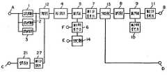
제1도는 본 발명의 한 실시예에 있어서의 텔레비전 튜너를 나타낸 것이다. 1-14는 VHF 대/UHF 대의 텔레비젼 방송신호 수신용 및 CATV 신호 수신용의 2중 슈우퍼 튜너부로 단자(A)로 부터 입력되는 VHF 대/UHF 대의 오프에어 텔레비젼 신호 및 CATV 신호가 높은 주파수의 제1IF 신호로 변환되고 다시금 낮은 주파수의 제2IF 신호(일본국내에서는 58.75MHz)로 변환되어서 단자(B)에 출력된다.1 shows a television tuner in one embodiment of the present invention. 1-14 is a double super tuner unit for receiving TV broadcast signals of the VHF band / UHF band and CATV signal reception, and the VHF band / UHF band off-air TV signal and CATV signal input from the terminal A It is converted to the first IF signal and again converted to the second IF signal of low frequency (58.75 MHz in Japan) and outputted to the terminal B.
(12) 및 (13)은 다이오우드스위치 또는 고주파 계전기등에 의한 전환회로로서, VHF 대/UHF 대의 텔레비젼 신호 및 CATV 신호의 수신용과, 위성 텔레비젼 방송의 수신용을 전활할 수 있다.(12) and (13) are switching circuits by diode switches, high frequency relays, and the like, which can dedicate the reception of television signals and CATV signals in the VHF / UHF band and the reception of satellite television broadcasts.
위성 텔레비젼 반송수신측으로 전환되었들때에는 단자(C)로 부터 입력된 BSIF 신호는, 입력대역필터(21) 및 제1IF 증폭기(22)를 통하여 전환회로(12)를 통하여 제1 믹서(5), 제1 국부발진기(6) 및 프레스캘러(14)의 공용회로를 통하여 전환회로(13)를 거쳐 제2IF 증폭기(25)통하여 단자(D)에 출력된다.When switched to the satellite television carrier receiving side, the BSIF signal inputted from the terminal C is transferred to the
제2도에 상기한 실시예에 있어서의 오프에어신호 및 CATV 신호를 수신하는 2중 슈우퍼 튜너부만을 추출하여 나타내었다.2 shows only the double super tuner section for receiving the off-air signal and the CATV signal in the above-described embodiment.
제3도에 있어서, 1-3은 입력대역필터, (4)는 RF 증폭기, (5)는 제1믹서, (6)은 제1국부발진기, (7)은 제1IF 증폭기, (8)은 대역필터(BPF), (9)는 제2 믹서, (10)은 제24국부발진기, (11)은 제 IF 증폭기, (14)는 프레스캘러이다.In Fig. 3, 1-3 is an input band filter, (4) is an RF amplifier, (5) is a first mixer, (6) is a first local oscillator, (7) is a first IF amplifier, and (8) is Band filters BPF, 9 are second mixers, 10 are 24th local oscillators, 11 are IF amplifiers, and 14 are press collars.
제2도에 있어서, (1),(2),(3)은 각 밴드(예컨대 VHF 대, CATV 대 UHF 대)등에 설치된 입력대역필터로서, 단자(A)로 부터 입력되어 동필터(1),(2),(3)의 어느 것인가를 통한 VHF 대/UHF 대의 텔레비젼 신호 또는 CATV 신호는, 자동이득 제어회로를 포함하는 넓은 대역 증폭기(4)에 의하여 증폭되어, 제1믹서(5)에 입력된다.In FIG. 2, (1), (2), and (3) are input band filters installed in each band (for example, VHF band, CATV band, and UHF band), and are input from the terminal A and are supplied with the same filter (1). The television signal or the CATV signal of the VHF band / UHF band through any one of (2) and (3) is amplified by a
동 입력신호는 제1국부발진기(6)로 부터 공급되는 제1국부발진신호와 제1믹서(5)에 의하여 혼합되어, 그것들의 주파수를 지닌 성분이 제1IF 신호로서 추출된다.The input signal is mixed by the first local oscillation signal supplied from the first
제IF 신호의 주파수는 900-1000MHz로 선정된다.The frequency of the IF signal is selected as 900-1000 MHz.
동 제1IF 신호는 제1IF 증폭기로 증폭되어, 대역필터(8)에 의하여 제1IF 신호만이 다시금 선정되어, 제2 믹서(9)에 입력된다. 동 제1IF 신호는 제2국부발진기(10)로 부터 공급되는 제2국부발진신호와 혼합되어 양자의 차의 주파수를 지닌 성분이 제2IF 신호로서 추출된다.The first IF signal is amplified by the first IF amplifier, and only the first IF signal is again selected by the
제2IF 신호의 주파수는 일본국내의 경우이면 58.75MHz로 선정된다. 제2IF 신호는 제2IF 증폭기(11)로 증폭되어서 제2IF 신호출력으로서 단자(B)로 부터 다음단의 VIF 회로에 출력된다.The frequency of the second IF signal is selected to 58.75 MHz in the case of Japan. The second IF signal is amplified by the second IF amplifier 11 and output from the terminal B to the next VIF circuit as the second IF signal output.
제1 국부발진기(6)에는 단자(F)에서 선국 제어회로로 부터의 선국용 동조주파수 제어전압이 공급된다. 또, 프레스캘러(14)에 의하여 제1국부발진기(6)의 국부발진신호를 분주하고, 그 분주출력을 단자(E)로 부터 선국 제어회로에 공급한다.The first
이상의 구성은 2중 슈우퍼방식의 튜너구성으로서 VHF 대/UHF-CATV 등의 다중 채널수신이나, 광대역수신에 유리한 시스템이며, 튜너로서는 또 일반적으로 사용되고 있지 않으나 금후 필요하게 되어 올 시스템이라 생각된다.The above configuration is a dual super tuner configuration, which is advantageous for multi-channel reception such as VHF / UHF-CATV and wideband reception, and is not generally used as a tuner, but is expected to be required in the future.
제1도의 텔레비젼 수신용 튜너는 기본적으로는 동 제2도의 2중 슈우퍼방식의 튜너와, 전술한 제4도의 시스템을 결합한 것이며 양자를 하나의 튜너로서 구성하기 위하여 전환회로(12),(13)를 설치하고 또한 제1국부발진 주파수를 선정하고 있다.The tuner for television reception of FIG. 1 basically combines the dual super tuner of FIG. 2 and the system of FIG. 4 described above, and includes a
여기에서 위성 텔레비젼 방송의 BSIF 신호를 단자(D)로 부터 출력하는 중간 주파수신호로 변환하기 위한 제1국부발진 주파수를 계산하면, BSIF 신호는 국내의 경우, 1035.98-13331.5MHz이며, 출력하는 중간주파수를 402.78MHz이라 하면, 제1국부발진 주파수는, 1035.98+402.78=1438.76(MHz)으로 부터 1331.54+402.78=1734.28(MHz)까지 변화시키면 충분하다.Here, when the first local oscillation frequency for converting the BSIF signal of the satellite television broadcast into the intermediate frequency signal outputted from the terminal D is calculated, the BSIF signal is 1035.98-13331.5MHz in Korea, If 402.78 MHz, the first local oscillation frequency is enough to change from 1035.98 + 402.78 = 1438.76 (MHz) to 1331.54 + 402.78 = 1734.28 (MHz).
한편, VHF 대/UHF 대 및 CATV용의 2중 슈우퍼방식 튜너의 편은, 제1IF 주파수는 방송신호 대역내를 피할 필요가 있으므로 해서 800MHz 이상을 선정하게 되고, 따라서 제1 국부발진 주파수는, 최소한 890-1570MHz의 범위에서 변화할 수 있게 된다.On the other hand, the dual super tuner tuner for VHF vs. UHF vs. CATV selects 800 MHz or more because the first IF frequency needs to be avoided in the broadcast signal band, so that the first local oscillation frequency is It will be able to change at least in the range of 890-1570MHz.
따라서 동 2중 슈우퍼방식 튜너 경우의 국부발진 가변범위를 약간 높은 쪽까지 뻗거나, 그렇지 않으면 제1IF 주파수를 높은 쪽으로 설정하면 위성 텔레비젼 방송용의 국부발진 주파수를 커버할 수 있어 제1 믹서(5), 국부발진기(6), 프레스캘러(7)를 공용할 수 있다.Therefore, if the local oscillation variable range in the case of the double super tuner is extended to a slightly higher side, or the first IF frequency is set higher, the local oscillation frequency for satellite television broadcasting can be covered. , The
이에 대하여 종래의 단일 슈우퍼방식의 튜너인 경우에는 국부발진 주파수도 낮기 때문에 국부발진기를 공용할 수 없고, 또 RF 증폭기(4)의 다음에 단간복동조회로가 필요하게 되므로 스위칭회로를 구성하기 어렵다. 2중 슈우퍼방식의 경우, 제1,2도와 같이 구성하면 광대역증폭기를 사용하므로 비동조의 회로로 할 수 있고, 임피이던스도 낮아서 스위칭회로를 구성하기 쉬운 이점이 있다.On the other hand, in the case of the conventional single-woofer type tuner, the local oscillation frequency is also low, so that the local oscillator cannot be shared, and since the inter-terminal demodulation circuit is required after the
이상과 같이 본 실시예에 의하면 VHF 대/UHF 대의 텔레비젼 신호와 CATV 신호의 수신용으로 2중 슈우퍼방식의 튜너를 사용하여, 제1 믹서회로(5)의 입력측과 출력측에 스위칭회로(12),(13)를 설치하여 BSIF 신호측과 전환함에 따라 국부발진기, 믹서, 프레스캘러를 공용할 수 있고, 대폭적인 소형화, 원가절하를 꾀할 수 있다.As described above, according to the present embodiment, the switching
다음에 본 발명의 다른 실시예에 대하여 도면을 참조하여 설명한다.Next, another embodiment of the present invention will be described with reference to the drawings.
제3도는 본 발명의 제2실시예의 텔레비젼 수신용 튜너의 구성을 타나낸 것이다.3 shows a configuration of a television reception tuner of a second embodiment of the present invention.
제3도 있어서 (1)-(11) 및 (14),(21)은 제1도중과 동일한 것이다. (12),(13)은 스위칭회로이지만 제1도의 경우와 삽입하는 위치가 다르다. 여기에서는 RF증폭기 (4)의 입력측에 스위칭회로(12)를 제 IF 증폭기(7)와 BPF(8)의 사이에 스위칭회로(13)를 각기 삽입하고 있다. 또 (27)은 제1IF 증폭기이다.In FIG. 3, (1)-(11), (14), and (21) are the same as in FIG. 12 and 13 are switching circuits, but the insertion positions are different from those in FIG. Here, the switching
이상과 같이 구성된 텔레비젼 수신용 튜너에 있어서, 스위칭회로(12)는 입력필터(1),(2),(3)와 RF 증폭기(4)사이에 설치되었으며, 스위칭회로(13)는 제1IF 증폭기(7)와 BPF(8)사이에 설치되어 있다. 그리하여 RF 증폭기(4)는 BSIF 신호수신시에 있어서의 제1IF 증폭기로서, 또 제1IF 증폭기(7)는 403MHz 대의 제2IF 증폭기로서 동작하게 되어, RF 증폭기(4), 제1믹서(5), 제1국부발진기(6) 제1IF 증폭기(7), 프레스캘러(14)의 블록을 공용화 할 수 있다.In the television tuner configured as described above, the switching
제1IF 증폭기(7)는 수레서 벨(a few dB)의 이득(gine)을 지닌 완충 증폭기를 기능하여 RF 증폭기(4)에 있어서의 1.3GHz 대에서의 이득저하를 보충함과 동시에 일반 텔레비젼 방송수신할때의 단자(C)에의 국부발진누설을 방지하는 완충기로서도 동작한다.The first IF
본 구성도, 전술한 바와 같이, 2중 슈우퍼방식이기 때문에, RF 증폭기(4)와 제1IF 증폭기(7)의 회로를 광대역 증폭기로서 공용할 수 있다.As described above, since the dual super system is used as described above, the circuits of the
이상과 같이 본 실시예에 의하면 공용화에 따라 제4도에 있어서의 22-26의 회로를 생략할 수 있고, 대폭적인 소형화와 원가절화를 할 수 있다.As described above, according to the present embodiment, the circuits in Figs. 22-26 in Fig. 4 can be omitted in accordance with common use, and the size and cost can be greatly reduced.
산업상의 이용가능성Industrial availability
이상과 같이 본 발명은 VHF 대/UHF 대의 오프-에어 텔레비젼 신호나, CATV 신호를 수신하는 튜너부를 2중 슈우퍼방식으로 구성하여, RF 증폭기, 믹서, 국구발진기, 프레스캘러, 제1IF 증폭기중 일부 또는 전부를 위성 텔레비젼 방송의 BSIF 신호 수신용 튜너의 제1IF 증폭기, 믹서, 국부발진기, 프레스캘러, 제2IF 증폭기의 일부 또는 전부와 입출력 스위칭회로를 통하여 공용화함에 따라 대폭적인 원가절하, 소형화를 꾀할 수 있어, 그 실용적 효과는 큰 것이다.As described above, according to the present invention, a tuner unit for receiving an off-air television signal or a CATV signal of a VHF band / UHF band is configured in a double super type, and a part of an RF amplifier, a mixer, a national oscillator, a press collar and a first IF amplifier Alternatively, all of the first IF amplifier, mixer, local oscillator, prescalar, and second IF amplifier of the BSIF signal receiving tuner of satellite television broadcasting can be shared with the input / output switching circuit, thereby greatly reducing cost and miniaturization. Its practical effect is great.
본 발명은 일반의 텔레비젼 방송신호나 CATV 신호, 위성 텔레비젼 방송신호를 수신하는 텔레비젼 수신용 튜너에 관한 것이다.BACKGROUND OF THE
제1도는 본 발명의 한 실시예에 있어서의 텔레비젼 수신용 튜너의 블록도.1 is a block diagram of a television reception tuner according to one embodiment of the present invention.
제2도는 2중 슈우터 튜너부의 블록도.2 is a block diagram of a double shooter tuner unit.
제3도는 본 발명에 다른 실시예에 있어서의 텔레비젼 수신용 튜너의 블록도.3 is a block diagram of a television reception tuner according to another embodiment of the present invention.
제4도는 종래예에 있어서의 위성 방송수신 튜너부의 블록도.4 is a block diagram of a satellite broadcast receiving tuner in the conventional example.
제5도는 종래예의 안일 슈우퍼 튜너의 블록도이다.Fig. 5 is a block diagram of a housework super tuner of the prior art.
Claims (5)
Translated fromKoreanApplications Claiming Priority (3)
| Application Number | Priority Date | Filing Date | Title |
|---|---|---|---|
| JP87-325863 | 1987-12-23 | ||
| JP62325863AJPH01168125A (en) | 1987-12-23 | 1987-12-23 | television tuner |
| PCT/JP1988/001313WO1989006072A1 (en) | 1987-12-23 | 1988-12-23 | Television tuner |
Publications (2)
| Publication Number | Publication Date |
|---|---|
| KR900701103A KR900701103A (en) | 1990-08-17 |
| KR920005218B1true KR920005218B1 (en) | 1992-06-29 |
Family
ID=18181458
Family Applications (1)
| Application Number | Title | Priority Date | Filing Date |
|---|---|---|---|
| KR1019890701573AExpiredKR920005218B1 (en) | 1987-12-23 | 1988-12-23 | TV tuner |
Country Status (6)
| Country | Link |
|---|---|
| US (1) | US5014349A (en) |
| EP (1) | EP0346495B1 (en) |
| JP (1) | JPH01168125A (en) |
| KR (1) | KR920005218B1 (en) |
| DE (1) | DE3889328T2 (en) |
| WO (1) | WO1989006072A1 (en) |
Families Citing this family (27)
| Publication number | Priority date | Publication date | Assignee | Title |
|---|---|---|---|---|
| JPH0346827A (en)* | 1989-07-14 | 1991-02-28 | Matsushita Electric Ind Co Ltd | Television tuner |
| JPH0646687B2 (en)* | 1989-12-13 | 1994-06-15 | 松下電器産業株式会社 | Mixer |
| KR930002204B1 (en)* | 1990-12-31 | 1993-03-27 | 삼성전자 주식회사 | Satellite broadcasting receiver built in tv |
| KR950000828B1 (en)* | 1991-12-11 | 1995-02-02 | 삼성전자 주식회사 | Multi-function tv |
| US5630214A (en)* | 1992-05-13 | 1997-05-13 | Hitachi, Ltd. | Wide-band receiving apparatus with local oscillating circuit |
| WO1994029949A1 (en)* | 1993-06-03 | 1994-12-22 | Deutsche Thomson-Brandt Gmbh | Terrestrial and satellite television reception tuner |
| US5572264A (en) | 1994-02-14 | 1996-11-05 | Hitachi, Ltd. | High definition TV signal receiver |
| US5548839A (en)* | 1994-10-14 | 1996-08-20 | Caldwell; Stephen P. | Wide band radio-frequency converter having multiple use of intermediate frequency translators |
| US5649312A (en)* | 1994-11-14 | 1997-07-15 | Fujitsu Limited | MMIC downconverter for a direct broadcast satellite low noise block downconverter |
| US6029054A (en)* | 1995-12-14 | 2000-02-22 | The United States Of America As Represented By The Secretary Of The Navy | MMIC receiver |
| EP0781048A1 (en)* | 1995-12-20 | 1997-06-25 | Philips Electronique Grand Public | Cable television distribution system |
| JPH09307827A (en)* | 1996-05-16 | 1997-11-28 | Sharp Corp | Tuning device |
| JPH09321544A (en)* | 1996-05-29 | 1997-12-12 | Dx Antenna Co Ltd | Converter for satellite signal reception antenna |
| JPH1056359A (en)* | 1996-08-09 | 1998-02-24 | Alps Electric Co Ltd | Digital broadcast receiver tuner |
| US5949472A (en)* | 1996-12-10 | 1999-09-07 | Intel Corporation | Method and apparatus for tuning channels for CATV and television applications |
| US6591091B1 (en) | 1998-11-12 | 2003-07-08 | Broadcom Corporation | System and method for coarse/fine PLL adjustment |
| JP3986195B2 (en)* | 1999-02-04 | 2007-10-03 | アルプス電気株式会社 | TV signal receiving tuner |
| JP2001326864A (en)* | 2000-05-17 | 2001-11-22 | Sony Corp | Tuner device |
| JP2002118795A (en)* | 2000-10-05 | 2002-04-19 | Alps Electric Co Ltd | Television signal reception tuner |
| JP3666466B2 (en)* | 2002-03-18 | 2005-06-29 | 株式会社村田製作所 | CATV tuner |
| US7027833B1 (en)* | 2003-04-03 | 2006-04-11 | The United States Of America As Represented By The Secretary Of The Navy | Dual band superheterodyne receiver |
| DE20313104U1 (en) | 2003-08-25 | 2004-01-15 | Trw Fahrwerksysteme Gmbh & Co Kg | Assembly for a chassis stabilization system |
| US7830456B1 (en)* | 2006-06-02 | 2010-11-09 | Anadigics, Inc | System and method for frequency multiplexing in double-conversion receivers |
| KR101092558B1 (en)* | 2006-12-06 | 2011-12-13 | 삼성전자주식회사 | Image signal selection method and image processing device |
| EP2449699A1 (en) | 2009-06-30 | 2012-05-09 | Thomson Licensing | Method of resending digital signals |
| JP5845974B2 (en)* | 2011-03-31 | 2016-01-20 | ソニー株式会社 | Receiving apparatus and receiving method |
| JP6146345B2 (en)* | 2014-03-04 | 2017-06-14 | ソニー株式会社 | Receiver, tuner and circuit |
Family Cites Families (8)
| Publication number | Priority date | Publication date | Assignee | Title |
|---|---|---|---|---|
| IT1057837B (en)* | 1976-04-05 | 1982-03-30 | Indesit | DEVICE FOR TUNING A TELEVISION |
| US4352209A (en)* | 1981-03-23 | 1982-09-28 | John Ma | Up-down frequency converter for cable T.V. |
| DE3226980A1 (en)* | 1982-07-19 | 1984-01-19 | Siemens AG, 1000 Berlin und 8000 München | Receiving arrangement for terrestrial television and satellite television and/or broadcasting |
| US4553264A (en)* | 1982-09-17 | 1985-11-12 | Matsushita Electric Industrial Co., Ltd. | Double superheterodyne tuner |
| JPS60149227A (en)* | 1984-01-13 | 1985-08-06 | Sony Corp | Shf receiver |
| KR870001910B1 (en)* | 1985-05-31 | 1987-10-21 | 삼성전자부품 주식회사 | High/low pass filter |
| JPS62230228A (en)* | 1986-03-31 | 1987-10-08 | Toshiba Corp | Two-frequency band reception system |
| GB2196197B (en)* | 1986-10-01 | 1990-09-19 | Telefunken Electronic Gmbh | Television tuner |
- 1987
- 1987-12-23JPJP62325863Apatent/JPH01168125A/enactivePending
- 1988
- 1988-12-23WOPCT/JP1988/001313patent/WO1989006072A1/ennot_activeCeased
- 1988-12-23USUS07/397,451patent/US5014349A/ennot_activeExpired - Fee Related
- 1988-12-23KRKR1019890701573Apatent/KR920005218B1/ennot_activeExpired
- 1988-12-23DEDE3889328Tpatent/DE3889328T2/ennot_activeExpired - Fee Related
- 1989
- 1989-07-05EPEP89900896Apatent/EP0346495B1/ennot_activeExpired - Lifetime
Also Published As
| Publication number | Publication date |
|---|---|
| DE3889328D1 (en) | 1994-06-01 |
| EP0346495A4 (en) | 1990-02-20 |
| WO1989006072A1 (en) | 1989-06-29 |
| DE3889328T2 (en) | 1994-11-03 |
| KR900701103A (en) | 1990-08-17 |
| US5014349A (en) | 1991-05-07 |
| EP0346495B1 (en) | 1994-04-27 |
| JPH01168125A (en) | 1989-07-03 |
| EP0346495A1 (en) | 1989-12-20 |
Similar Documents
| Publication | Publication Date | Title |
|---|---|---|
| KR920005218B1 (en) | TV tuner | |
| CA1092733A (en) | Multi-band tuner | |
| CA1069629A (en) | Multi-band tuner with fixed broadband input filters | |
| EP0149533B2 (en) | Apparatus for receiving super high frequency signals | |
| KR920010240B1 (en) | TV tuner | |
| US5355532A (en) | Television tuner unit having shield housing | |
| EP1317073B1 (en) | Tuner arrangement and set top box | |
| KR100445108B1 (en) | Receiver, Receiving Method and Terminal Device | |
| US7212782B2 (en) | Low-noise block down-converter and satellite broadcasting receiving apparatus | |
| US20070105513A1 (en) | Radio reception device for receiving both terrestrial and satellite digital broadcasting | |
| US5995818A (en) | Low noise block downconverter | |
| US4315333A (en) | Circuit arrangement for a wide-band VHF-UHF television double superheterodyne receiver | |
| JP3471219B2 (en) | DBS tuner for satellite broadcast reception | |
| US5630214A (en) | Wide-band receiving apparatus with local oscillating circuit | |
| US5093922A (en) | Receiving apparatus for receiving a bs-if signal converted into a superhigh band or uhf band | |
| US5999572A (en) | Digital broadcasting receiver tuner | |
| JP4387030B2 (en) | Satellite digital broadcasting down converter for headend | |
| KR920002534B1 (en) | Terrestrial and satellite broadcasting system | |
| JP2856767B2 (en) | Receiver and local oscillator circuit used for it | |
| KR960003559B1 (en) | Setting method for osc frequency | |
| KR970004004Y1 (en) | Television receiver with built-in satellite broadcasting receiver | |
| KR970007041Y1 (en) | Tuner | |
| KR950002432B1 (en) | Wideband lnb | |
| KR930002095Y1 (en) | 2-input satellite tuner | |
| JP2730056B2 (en) | Television tuner |
Legal Events
| Date | Code | Title | Description |
|---|---|---|---|
| A201 | Request for examination | ||
| PA0105 | International application | St.27 status event code:A-0-1-A10-A15-nap-PA0105 | |
| PA0201 | Request for examination | St.27 status event code:A-1-2-D10-D11-exm-PA0201 | |
| R17-X000 | Change to representative recorded | St.27 status event code:A-3-3-R10-R17-oth-X000 | |
| PG1501 | Laying open of application | St.27 status event code:A-1-1-Q10-Q12-nap-PG1501 | |
| G160 | Decision to publish patent application | ||
| PG1605 | Publication of application before grant of patent | St.27 status event code:A-2-2-Q10-Q13-nap-PG1605 | |
| E701 | Decision to grant or registration of patent right | ||
| PE0701 | Decision of registration | St.27 status event code:A-1-2-D10-D22-exm-PE0701 | |
| GRNT | Written decision to grant | ||
| PR0701 | Registration of establishment | St.27 status event code:A-2-4-F10-F11-exm-PR0701 | |
| PR1002 | Payment of registration fee | St.27 status event code:A-2-2-U10-U12-oth-PR1002 Fee payment year number:1 | |
| PR1001 | Payment of annual fee | St.27 status event code:A-4-4-U10-U11-oth-PR1001 Fee payment year number:4 | |
| PR1001 | Payment of annual fee | St.27 status event code:A-4-4-U10-U11-oth-PR1001 Fee payment year number:5 | |
| PR1001 | Payment of annual fee | St.27 status event code:A-4-4-U10-U11-oth-PR1001 Fee payment year number:6 | |
| PR1001 | Payment of annual fee | St.27 status event code:A-4-4-U10-U11-oth-PR1001 Fee payment year number:7 | |
| PN2301 | Change of applicant | St.27 status event code:A-5-5-R10-R13-asn-PN2301 St.27 status event code:A-5-5-R10-R11-asn-PN2301 | |
| R18-X000 | Changes to party contact information recorded | St.27 status event code:A-5-5-R10-R18-oth-X000 | |
| FPAY | Annual fee payment | Payment date:19990618 Year of fee payment:8 | |
| PR1001 | Payment of annual fee | St.27 status event code:A-4-4-U10-U11-oth-PR1001 Fee payment year number:8 | |
| LAPS | Lapse due to unpaid annual fee | ||
| PC1903 | Unpaid annual fee | St.27 status event code:A-4-4-U10-U13-oth-PC1903 Not in force date:20000630 Payment event data comment text:Termination Category : DEFAULT_OF_REGISTRATION_FEE | |
| PC1903 | Unpaid annual fee | St.27 status event code:N-4-6-H10-H13-oth-PC1903 Ip right cessation event data comment text:Termination Category : DEFAULT_OF_REGISTRATION_FEE Not in force date:20000630 | |
| R18-X000 | Changes to party contact information recorded | St.27 status event code:A-5-5-R10-R18-oth-X000 | |
| P22-X000 | Classification modified | St.27 status event code:A-4-4-P10-P22-nap-X000 | |
| PN2301 | Change of applicant | St.27 status event code:A-5-5-R10-R13-asn-PN2301 St.27 status event code:A-5-5-R10-R11-asn-PN2301 |