KR920002496B1 - Lacing assembly of shoes - Google Patents
Lacing assembly of shoesDownload PDFInfo
- Publication number
- KR920002496B1 KR920002496B1KR1019850700015AKR850700015AKR920002496B1KR 920002496 B1KR920002496 B1KR 920002496B1KR 1019850700015 AKR1019850700015 AKR 1019850700015AKR 850700015 AKR850700015 AKR 850700015AKR 920002496 B1KR920002496 B1KR 920002496B1
- Authority
- KR
- South Korea
- Prior art keywords
- strap
- footwear
- ties
- front cover
- receiving means
- Prior art date
- Legal status (The legal status is an assumption and is not a legal conclusion. Google has not performed a legal analysis and makes no representation as to the accuracy of the status listed.)
- Expired
Links
Images


Classifications
- A—HUMAN NECESSITIES
- A43—FOOTWEAR
- A43C—FASTENINGS OR ATTACHMENTS OF FOOTWEAR; LACES IN GENERAL
- A43C1/00—Shoe lacing fastenings
- Y—GENERAL TAGGING OF NEW TECHNOLOGICAL DEVELOPMENTS; GENERAL TAGGING OF CROSS-SECTIONAL TECHNOLOGIES SPANNING OVER SEVERAL SECTIONS OF THE IPC; TECHNICAL SUBJECTS COVERED BY FORMER USPC CROSS-REFERENCE ART COLLECTIONS [XRACs] AND DIGESTS
- Y10—TECHNICAL SUBJECTS COVERED BY FORMER USPC
- Y10T—TECHNICAL SUBJECTS COVERED BY FORMER US CLASSIFICATION
- Y10T24/00—Buckles, buttons, clasps, etc.
- Y10T24/37—Drawstring, laced-fastener, or separate essential cooperating device therefor
- Y10T24/3768—Drawstring, laced-fastener, or separate essential cooperating device therefor having loop or sleeve shaped directing means
Landscapes
- Footwear And Its Accessory, Manufacturing Method And Apparatuses (AREA)
- Acyclic And Carbocyclic Compounds In Medicinal Compositions (AREA)
- Heterocyclic Compounds That Contain Two Or More Ring Oxygen Atoms (AREA)
Abstract
Translated fromKoreanDescription
Translated fromKorean[발명의 명칭][Name of invention]
신발류의 끈 결속구Footwear Binding
[도면의 간단한 설명][Brief Description of Drawings]
제1도는 끈 결속구를 갖는 부츠의 사시도.1 is a perspective view of a boot having lace fasteners.
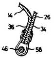
제2도는 이중 고리 체결기를 보여주는 앞닫이 판 부분의 확대 단면도.2 is an enlarged cross-sectional view of a front plate portion showing a double loop fastener.
제3도는 단일 고리 체결기를 보여주는 앞닫이 판 부분의 확대 단면도.3 is an enlarged cross-sectional view of the front plate portion showing a single loop fastener.
[발명의 상세한 설명]Detailed description of the invention
[기술분야][Technical Field]
본 발명은 일반적으로 신발류의 끈 결속구의 개량에 관한 것이며, 특히 신발류의 상부 및 하부 앞닫이 구역(vamp section) 사이에서 단일의 연속적인 끈을 사용하여 발의 상이한 부분들에 각기 적합하도록 신발류의 상부 및 하부 앞닫이 구역을 선택적으로 조절 및 유지할 수 있게 하는 신발류의 개선된 끈 결속구에 관한 것이다.FIELD OF THE INVENTION The present invention relates generally to the improvement of the strap ties of footwear, in particular the upper and lower portions of footwear to be adapted to different parts of the foot, respectively, using a single continuous strap between the upper and lower vamp sections of the footwear. An improved strap ties of footwear that allow for selective adjustment and maintenance of the front cover area.
[배경기술][Background]
본 발명에 가장 근접된 두개의 선행 특허로 본 출원의 발명자와 동일 발명자에게 허여된 미합중국 특허 제3,546,796호와 제4,200,998호를 들 수 있다. 전자의 특허에는 상부 및 하부 앞닫이 구역이 분리된 운동화가 기재되어 있다. 이 운동화에서는 각각의 앞닫이 구역에 별도의 끈을 사용하도록 되어 있어, 각각의 앞닫이 구역을 발의 별도의 부분에 맞도록 조절할 수 있으나, 각각의 앞닫이 구역에 별도의 끈을 사용하게 되어 각각의 운동화에서 끈의 단부가 4개가 되고 매듭이 2개가 되는 단점이 있게 된다. 후자의 특허에서는 상부 및 하부 앞닫이 구역 사이로 연장되는 단일의 연속적인 끈과 상부 및 하부 앞닫이 구역 사이에 위치한 클램프(clamp)를 사용하여 신발의 착용 상태를 선택적으로 조절하여 앞서의 문제점을 어느 정도 극복하였다. 후자의 특허에서는 제안된 끈 결속구는 부가적인 끈의 단부와 매듭을 갖는 앞서의 문제점을 어느 정도 해결 하였으나, 각 신발에 마련된 중심에 위치한 단일 클램프는 약간 복잡하게 되어 있어 특정 경우에 필요한 조작에 비해 보다 숙련된 조작을 요하게 된다.The two prior patents closest to the present invention are US Pat. Nos. 3,546,796 and 4,200,998 issued to the inventors of the present application and the same inventors. The former patent describes sneakers with separate upper and lower forepan sections. In these sneakers, a separate strap is used for each front section, so each front section can be adjusted to fit a separate part of the foot, but a separate strap is used for each front section, There is a disadvantage that the end of the four is four knots. The latter patent overcomes some of the previous problems by selectively adjusting the state of wearing of the shoe using a single continuous strap extending between the upper and lower forepan sections and a clamp located between the upper and lower forefront sections. . The latter patent solves some of the previous problems with additional strap ends and knots, but the centrally located single clamp on each shoe is slightly more complicated than the required operation in certain cases. Skilled operation is required.
본 발명의 끈 결속구는 선행 기술에서 사용하지 않던 방법으로 전기한 문제점을 해결하게 된다.The string binding tool of the present invention solves the above-described problems by a method not used in the prior art.
[발명의 개시][Initiation of invention]
신발류에 사용하는 본 발명의 끈 결속구는 군화 또는 작업화와 같은 목이 긴 구두(부츠(boot))에 적합하며, 하부 앞닫이 구역을 상부 앞닫이 구역과는 별도로 착용 상태를 조절 및 유지하며, 통상적인 외양을 갖고 있고 상부단부에서 통상적으로 묶을 수 있는 단일의 연속적인 끈을 사용한다.The strap fastener of the present invention for use in footwear is suitable for long neck shoes (boots) such as boots or work shoes, and adjusts and maintains the lower front cover area separately from the upper front cover area, and maintains the normal appearance. Use a single continuous strap that has and can usually be tied at the upper end.
끈 결속구는 대향된 앞닫이 판 부분(vamp panel portion)을 각각 포함하는 제1 및 제2앞닫이 구역(vamp section)을 마련한다. 하부의 제1앞닫이 판 부분은 하부단부에 있는 대향된 끈 수용 수단과 이 끈 수용 수단에 상방으로 인접하여 관련 앞닫이 판 부분에 부착된 끈 수용 체결 수단을 포함한다. 제2앞닫이 판 부분은 다수의 대향된 끈 수용 수단을 포함한다. 대향된 측면 길이부를 갖는 단일의 연속적인 끈을 마련하는데, 상기 측면 길이부는 상기 제1앞닫이 판 부분의 대향된 끈 수용 수단과 대향된 끈 수용 체결 수단에 수용되며, 이 측면 길이부는 또한 상기 제1 및 제2앞닫이 구역 사이에서 연장되어 상기 제2앞닫이 판부분의 대향된 끈 수용 수단에 수용되고, 상기 끈은 상기 끈 수용 체결 수단에 선택적으로 체결될 수 있는 상태로 수용되어 제1앞닫이 구역을 제2앞닫이 구역과는 사실상 독립적으로 조절 및 유지될 수 있게 한다.The string tie provides a first and a second vamp section, each comprising an opposing vamp panel portion. The lower first forearm plate portion includes opposing strap receiving means at the lower end and strap receiving fastening means attached upwardly adjacent to and attached to the associated forearm plate portion. The second front cover plate portion includes a plurality of opposed string receiving means. A single continuous strap having opposite side lengths is provided, the side lengths being received in the strap receiving fastening means opposite the opposed string receiving means of the first front cover plate portion, the side lengths also being in the first length. And between the second foreclosure zones and received in the opposing strap receiving means of the second foreclosure plate portion, wherein the strap is received in a state capable of being selectively fastened to the strap receiving fastening means to define the first foreclosure zone. 2 Allows for adjustment and maintenance independently of the front door area.
본 발명의 특징은 제1앞닫이 판 부분에 있는 끈 수용 체결 수단이 끈을 고정하는 이중 고리 체결기라는 점이다.A feature of the present invention is that the string receiving fastening means in the first front cover plate portion is a double loop fastener which fixes the string.
본 발명의 다른 특징은 각각의 이중 고리 체결기는, 앞닫이 판 부분에 부착되어 개구부를 갖는 기부 부분과 상기 기부 부분의 개구부에 의해 회동식으로 수용된 회동부를 각각 갖는 1쌍의 겹쳐져 있는 와이어 고리요소(wire loop element)를 포함한다는 점이다.Another feature of the present invention is that each double loop fastener has a pair of overlapping wire loop elements each having a base portion having an opening attached to the front plate portion and having a pivot portion pivotally received by the opening of the base portion. wire loop element).
본 발명의 또다른 특징은 와이어 고리 요소들은 겹쳐져 있는 고리들의 체결 작용을 용이하게 하는 외측정점 부분을 제공하도록 형태가 삼각형이라는 점이다.Another feature of the invention is that the wire loop elements are triangular in shape to provide an outer vertex portion that facilitates the fastening action of the overlapping rings.
본 발명의 또다른 특징은 끈 수용 수단을 갖는 대향된 앞닫이 판 부분을 포함하는 제2앞닫이 구역에 상방으로 인접한 제3앞닫이 구역이 제공된다는 점이다.Another feature of the invention is that a third foreclosure zone is provided upwardly adjacent to a second foreclosure zone comprising an opposing foreclosure plate portion with strap receiving means.
본 발명의 또다른 특징은 신발류가 제3앞닫이 구역을 제공하도록 상방으로 연장하는 측면 다리부를 갖는 부츠라는 점이다.Another feature of the invention is that the footwear is a boot with side legs extending upwards to provide a third foreclosure zone.
본 발명의 또다른 특징은 제1앞닫이 판 부분의 끈 수용 수단들은 끈 구멍(eyelet)들이고, 제1앞당이 판부분의 끈 수용 체결 수단들은 이중 고리 체결기들이고, 제3앞닫이 구역의 끈 수용 수단은 U-형 단일 고리 요소라는 점이다.Another feature of the invention is that the strap receiving means of the first forepan plate portion are eyelets, the strap receiving fastening means of the first forepan plate portion are double loop fasteners, and the strap receiving means of the third forepan section. Is a U-shaped single ring element.
본 발명의 또다른 특징은 제1 및 제2앞닫이 구역이 앞닫이의 가요성을 좋게 하기 위해 상방으로 인접한 앞닫이 판 부분들 사이의 V-형 분할부(split)들에 의해 분리된다는 점이다.Another feature of the invention is that the first and second forearm zones are separated by V-shaped splits between upwardly adjoining forearm plate portions to improve the flexibility of the forearm.
[발명의 최선 실시 형태]Best Mode of the Invention
도면의 참조 부호 및 제1도를 참조하여 보면, 부츠(10)은 밑창(12), 밑창(12)에 부착된 전방 발끝부분(14), 상기 전방 발끝부분(14)의 일체로 형성되고 자유 상부 단부(18)을 갖는 설편(16)을 포함함을 알 수 있다. 부츠(10)은 또한 그 하부단부에서 밑창에 부착되고 측면 뒷닫이 부분(quarter : 24) 및 상부 측면 부분(26)을 포함하는 대향된 측면부(20)도 포함한다. 도시한 바와 같이, 부츠는 또한 참조 부호 28로 표시한 앞닫이(vamp)도 포함한다.Referring to the reference numerals and FIG. 1 of the drawings, the
도시한 실시예에서, 앞닫이(28)은 발끝부분(14)에 인접하여 위치하고 대향하여 위치된 앞닫이 판 부분(30)을 갖는 제1앞닫이 구역(29), 제1앞닫이 구역에 상방으로 인접하여 위치하고 대향하여 위치된 앞닫이판 부분(32)를 갖는 제2앞닫이 구역(31) 및 제2앞닫이 구역에 상방으로 인접하여 위치하고 대향하여 위치한 앞닫이 판 부분(34)를 갖는 제3앞닫이 구역(33)을 포함한다.In the illustrated embodiment, the
제3도에 개략적으로 도시한 설편의 측면 연부(36)은 앞닫이 판 부분에 부착된다. 제1도에 상세히 도시한 바와 같이, 제1 및 제2앞닫이 판 부분(30, 32)는 V-형 분할부(40)에 의해 분리되고 제2 및 제3앞닫이판 부분(32, 34)는 V-형 분할부(42)에 의해 분리되어 있어서, 이들 분할부가 앞닫이 구역들의 독립적인 개별적인 이동이 용이하도록 앞닫이에 가용성을 제공하게 된다.The
이제 부츠(10)의 끈 연결에 관해 고찰해 보면, 상기 부츠에는 보강 단부(48)에서 종결되는 단일의 연속적인 끈(44)가 제공됨을 알 수 있다. 끈(44)는 앞닫이 구역과 협력하여 끈 결속구를 제공하는데, 여기에서 끈은 제1, 제2 및 제3앞닫이 판 부분(30, 32, 34)를 각각 상호 연결시키고 착용자가 편안하도록 상기 앞닫이판 부분을 꼭 맞게 조절한다. 특히, 제1앞닫이 판 부분에는 끈 수용 수단을 구성하는 다수의 대향된 끈 구멍(52)을 제공하고, 끈 수용 체결 수단을 구성하는 특히 중요한 이중 고리 체결기(54)를 제공한다. V-형 분할부(40)에 의해 제1앞닫이 판 부분(30)으로부터 분리되어 있는 제2앞닫이 판 부분(32)는 끈의 측면 길이부(46)을 수용하는 수단을 제공하는 다수의 끈 구멍(56)을 포함한다. 마지막으로, V-형 분할부(42)에 의해 제2앞닫이 판 부분(32)로부터 분리되어 있는 제3앞당이 판 부분(34)는 리벳이음에 의해 제3앞닫이 판 부분(34)에 부착되고 상기 앞닫이 판 부분의 연부로부터 이격되어 상기 연부와 협동하여 끈 측면 길이부(46)을 수용하는 수단을 제공하는 만곡부(bight portion)를 갖는 다수의 U-형 단일 고리 요소(U-shaped single loop element)(58)을 포함한다.Considering the strap connection of the
적합한 실시예에서, 제2도에 상세히 도시한 바와 같이 대향된 각각의 이중 고리 체결기(54)는 접혀진 판(strap)으로 형성되어 앞닫이 및 설편에 리벳(62)에 의해 부착되어 개구부(64)를 형성하는 기부 부분(60)을 포함한다. 또한, 이중 "D"링 체결기로 호칭되는 체결기(54)는 1쌍의 대체로 삼각형이고, 겹쳐져 있는 동일한 와이어 고리 요소(66, 68)을 포함하는데, 상기 와이어 고리 요소들은 개구부(64)에 회동식으로 수용되는 회동부(70) 및 정점 부분(72)를 각각 갖고 있다.In a suitable embodiment, each of the opposed
제2도에 상세히 도시한 바와 같이, 각 끝의 측면 길이부(46)은 상부 및 하부 와이어 고리 요소(66, 68)을 통과한 후에 다시 하부 와이어 고리 요소(68)내로 접혀진 상태에서 체결 상태로 통과하게 되어, 끈에 장력을 가하게 되면 마찰 연결식으로 끈이 고정되게 된다. 이러한 상관 관계로 인해 착용자의 착용감을 좋게 하기 위해 제1 및 제2앞닫이 구역을 독립적으로 그리고 선택적으로 조절할 수가 있게 된다.As shown in detail in FIG. 2, the
본 발명의 끈 결속구의 구조적인 특징 및 기능상의 장점은 전술한 설명으로 충분하다고 생각되나, 설명의 완전을 기하기 위해 앞닫이 구역들의 착용 상태 조절 및 끈 결속구의 체결에 대해 간단히 설명하겠다.Structural features and functional advantages of the strap fastener of the present invention is considered to be sufficient as the above description, but for the sake of completeness of the description will be briefly described for the adjustment of the wearing conditions of the front and rear sections and the fastening of the strap tie.
처음에 끈(44)을 제1앞닫이 판 부분(30)의 끈 구멍(52) 및 이중 고리 체결기와, 제2앞닫이 판 부분(32)의 끈 구멍(56) 및 제3앞닫이 판 부분(34)의 U-형 단일 고리 요소(58)을 통해 느슨하게 끼운다. 따라서 착용자의 발을 부츠(10)내로 쉽게 삽입할 수가 있다.Initially, the string 44 is tied to the
위와 같은 동작이 끝난 후에, 제1앞닫이 구역의 착용 상태는 이중 고리 체결기(54) 아래쪽의 끈의 측면 길이부(46)의 느슨한 부분을 당기고 끈을 제2도에 점선으로 도시한 바와 같이 와이어 고리 요소(66, 68)을 통해 당겨 조절할 수 있다. 제1앞닫이 구역내에 있는 끈의 측면 길이부(46)은 그 끈의 상부, 부분을 잡아 당김으로써 조절되는데, 이러한 동작은 상부 및 하부 와이어 고리 요소(66, 68)을 상호 접근시키고 끈에 장력이 가해질 때 와이어 고리 요소들을 결합상태로 당기게 되기 때문에 끈을 효율적으로 고정시키게 된다. 이러한 조절 과정이 끝난 후에, 착용자의 전방 발 부분 및 발끝은 하부의 제1앞닫이 구역에 의해 착용자가 원하는 착용 상태로 편안하게 조여지게 된다. 이중 고리 체결기(54) 위쪽의 나머지 끈 부분은 제1앞닫이 구역의 착용상태를 유지하면서 조절하여, 제2(중간) 앞닫이 구역, 제3(상부) 앞닫이 구역을 제1앞닫이 구역과는 별도로 조절하여 상기 구역들 내에 위치하는 발의 부분을 편안하게 조여지게 한다. 상부의 두개의 앞닫이 구역은 이중 고리 체결기(54)의 체결 작용이 있기 때문에 하부 앞닫이 구역의 착용 상태를 방해하지 않고 별도로 조절할 수가 있다. 그 다음에 끈의 자유단부들을 부츠(10)의 상부에 매듭을 묶거나 통상적인 다른 방법으로 고정시킬 수 있다.After the above operation is completed, the wearing state of the first foreclosure section pulls the loose portion of the
전술한 방법과는 달리, 제1앞닫이 구역의 끈을 양호한 착용감을 제공할 수 있도록 조절하고 다음에 끈의 잔여 부분을 제2 및 제3앞닫이 구역의 끈 구멍 체결기 내에 끼울 수가 있다. 어떠한 경우에도, 제1앞닫이 구역의 대향하여 위치된 이중 고리 체결기는 착용자가 편안하도록 독립적으로 조절되며 앞닫이 구역을 다시 조절하기 위해 착용자가 행동을 취하기 전까지는 조절된 상태로 유지하여, 부츠를 벗기 위해 상부 끈 부분을 풀 때에도 착용자의 발에 조절된 상태로 유지된다. 적합한 실시예를 부츠에 관해 설명하였으나, 두개 또는 그 이상의 앞닫이 구역을 갖는 다른 신발류에도 사용할 수가 있다.Unlike the method described above, the straps of the first front cover area can be adjusted to provide a good fit and then the remainder of the straps can be inserted into the strap hole fasteners of the second and third front cover areas. In any case, the opposingly positioned double loop fasteners of the first front door area are independently adjusted for the wearer's comfort and remain adjusted until the wearer takes action to re-adjust the front door area to remove the boots. Even when the upper strap portion is released, it is kept adjusted to the wearer's foot. While suitable embodiments have been described with respect to boots, they can also be used for other footwear having two or more front lid sections.
Claims (8)
Translated fromKoreanApplications Claiming Priority (4)
| Application Number | Priority Date | Filing Date | Title |
|---|---|---|---|
| US06/525,725US4538367A (en) | 1983-08-23 | 1983-08-23 | Footwear lacing assembly |
| US525725 | 1983-08-23 | ||
| US525,725 | 1983-08-23 | ||
| PCT/US1984/001332WO1985000959A1 (en) | 1983-08-23 | 1984-08-21 | Footwear lacing assembly |
Publications (2)
| Publication Number | Publication Date |
|---|---|
| KR850700004A KR850700004A (en) | 1985-10-21 |
| KR920002496B1true KR920002496B1 (en) | 1992-03-27 |
Family
ID=24094373
Family Applications (1)
| Application Number | Title | Priority Date | Filing Date |
|---|---|---|---|
| KR1019850700015AExpiredKR920002496B1 (en) | 1983-08-23 | 1984-08-21 | Lacing assembly of shoes |
Country Status (12)
| Country | Link |
|---|---|
| US (1) | US4538367A (en) |
| EP (1) | EP0153399B1 (en) |
| JP (1) | JPS60502189A (en) |
| KR (1) | KR920002496B1 (en) |
| AU (1) | AU575077B2 (en) |
| CA (1) | CA1220337A (en) |
| DE (2) | DE8490137U1 (en) |
| DK (1) | DK178885A (en) |
| MX (1) | MX159122A (en) |
| NZ (1) | NZ209194A (en) |
| WO (1) | WO1985000959A1 (en) |
| ZA (1) | ZA846453B (en) |
Families Citing this family (37)
| Publication number | Priority date | Publication date | Assignee | Title |
|---|---|---|---|---|
| US4670949A (en)* | 1985-11-01 | 1987-06-09 | Autry Industries, Inc. | Staggered speed lace eyelets and method of lacing |
| US4899466A (en)* | 1986-08-10 | 1990-02-13 | Kaepa, Inc. | Footwear lace locking assembly |
| WO1989000387A1 (en)* | 1987-07-17 | 1989-01-26 | Kaepa, Inc. | Footwear lace locking assembly |
| US5189818A (en)* | 1986-08-10 | 1993-03-02 | Kaepa, Inc. | Footwear lace locking assembly |
| IT208224Z2 (en)* | 1986-10-15 | 1988-04-11 | Superga Spa | IMPROVEMENT IN SPORTS FOOTWEAR IN PARTICULAR SUITABLE FOR BASKETBALL. |
| CH674445A5 (en)* | 1988-01-28 | 1990-06-15 | Raichle Sportschuh Ag | Sports shoe or boot - has double ring clamping eyelet for laces, with two rings forming fastening with parallel pivot axles |
| US4947560A (en) | 1989-02-09 | 1990-08-14 | Kaepa, Inc. | Split vamp shoe with lateral stabilizer system |
| US5257470A (en)* | 1989-03-17 | 1993-11-02 | Nike, Inc. | Shoe bladder system |
| CA2012140C (en)* | 1989-03-17 | 1999-01-26 | Daniel R. Potter | Athletic shoe with pressurized ankle collar |
| CA2012141C (en)* | 1989-03-17 | 1999-07-27 | Daniel R. Potter | Customized fit shoe and bladder and valve assembly therefor |
| US5253435A (en)* | 1989-03-17 | 1993-10-19 | Nike, Inc. | Pressure-adjustable shoe bladder assembly |
| US5042120A (en)* | 1989-12-01 | 1991-08-27 | K-Swiss Inc. | Shoe lacing system |
| US5109581A (en)* | 1991-01-18 | 1992-05-05 | Gould Murray J | Device and method for securing a shoe |
| FR2697730B1 (en)* | 1992-11-06 | 1995-02-10 | Salomon Sa | Shoe with tightening by flexible link. |
| USD345246S (en) | 1993-06-04 | 1994-03-22 | Nike, Inc. | Shoe upper |
| US5859073A (en)* | 1994-05-27 | 1999-01-12 | Ciba Specialty Chemicals Corportation | Polyester/polycarbonate blends having enhanced properties |
| IT1279259B1 (en)* | 1995-01-27 | 1997-12-09 | Nordica Spa | CLAMPING DEVICE, ESPECIALLY FOR SPORTS SHOES |
| USD385692S (en)* | 1995-07-31 | 1997-11-04 | H.H. Brown Shoe Co. (Canada) Ltd. | Boot upper |
| USD377114S (en)* | 1995-11-22 | 1997-01-07 | Fila U.S.A., Inc. | Shoe eyelets |
| AT405894B (en)* | 1996-07-22 | 1999-12-27 | Mark Rudolf | ELEMENT FOR CLOSING AN OPENING, IN PARTICULAR A CLAMPING DEVICE |
| FR2752686B1 (en)* | 1996-08-29 | 1998-11-06 | Salomon Sa | LACE WITH VARIABLE SECTION FOR SPORTS SHOES AND SPORTS SHOES PROVIDED WITH SUCH A LACE |
| US6219891B1 (en)* | 1997-01-21 | 2001-04-24 | Denis S. Maurer | Lacing aid and connector |
| USD387194S (en)* | 1997-01-24 | 1997-12-09 | Vans, Inc. | Shoe upper |
| US7281341B2 (en) | 2003-12-10 | 2007-10-16 | The Burton Corporation | Lace system for footwear |
| DE102005056077B4 (en)* | 2005-11-24 | 2017-05-11 | Deeluxe Sportartikel Handels Gmbh | Boots |
| US8215033B2 (en)* | 2009-04-16 | 2012-07-10 | Nike, Inc. | Article of footwear for snowboarding |
| US8474157B2 (en) | 2009-08-07 | 2013-07-02 | Pierre-Andre Senizergues | Footwear lacing system |
| USD672538S1 (en)* | 2010-03-01 | 2012-12-18 | Alessandro Marcolin | Footwear |
| USD660565S1 (en)* | 2010-04-22 | 2012-05-29 | Tod's S.P.A. | Shoe |
| USD635759S1 (en)* | 2010-10-21 | 2011-04-12 | Columbia Sportswear North America, Inc. | Footwear |
| USD701373S1 (en) | 2011-11-24 | 2014-03-25 | Tod's S.P.A. | Shoe |
| USD683530S1 (en)* | 2012-03-19 | 2013-06-04 | LaCrosse Footwear | Boot |
| USD687624S1 (en)* | 2012-11-09 | 2013-08-13 | Rocky Brands, Inc. | Footwear upper |
| US9622539B2 (en)* | 2013-03-14 | 2017-04-18 | Bauer Hockey, Inc. | Skate boot having a lace member with at least one opening |
| US9723890B2 (en)* | 2013-11-22 | 2017-08-08 | Nike, Inc. | Article of footwear incorporating a knitted component with body and heel portions |
| USD901848S1 (en)* | 2019-07-02 | 2020-11-17 | Joseph Mazgaj | Combat boot |
| USD1079208S1 (en)* | 2023-10-27 | 2025-06-17 | Xiamen Lanzhou Household Products Co., Ltd. | Shoe |
Family Cites Families (10)
| Publication number | Priority date | Publication date | Assignee | Title |
|---|---|---|---|---|
| CH25001A (en)* | 1901-11-26 | 1903-03-15 | Emile Savoye | Multi-eyed lacing eyelet |
| GB191207868A (en)* | 1912-04-01 | 1912-10-24 | Joseph Onesime Nadeau | Improvements in or relating to Boots and Shoes. |
| US1095700A (en)* | 1912-06-01 | 1914-05-05 | Amon D Bostwick | Tying device. |
| GB366177A (en)* | 1930-11-18 | 1932-02-04 | Mobbs Brothers Embekay Ltd | Improvements relating to boot uppers |
| US1830646A (en)* | 1931-05-06 | 1931-11-03 | Grundlehner Ernest | Shoe lace fastener |
| CH181518A (en)* | 1935-02-14 | 1935-12-15 | Walder & Co | Laces for shoes and the like. |
| AT193275B (en)* | 1955-01-31 | 1957-11-25 | Schuhfabrik Koeflach F Herunte | Inner lacing for a ski boot with an inner and outer shaft |
| US3085823A (en)* | 1960-12-13 | 1963-04-16 | Baere Richard D De | Self-gripping and readily releasable rope tie |
| US3546796A (en)* | 1969-04-21 | 1970-12-15 | Thomas M Adams | Special sport shoe for people with high insteps |
| US4200998A (en)* | 1978-05-30 | 1980-05-06 | Adams Thomas M | Lacing assembly for a shoe |
- 1983
- 1983-08-23USUS06/525,725patent/US4538367A/ennot_activeExpired - Lifetime
- 1984
- 1984-08-13NZNZ209194Apatent/NZ209194A/enunknown
- 1984-08-16CACA000461156Apatent/CA1220337A/ennot_activeExpired
- 1984-08-20ZAZA846453Apatent/ZA846453B/enunknown
- 1984-08-21EPEP84903260Apatent/EP0153399B1/ennot_activeExpired
- 1984-08-21JPJP59503224Apatent/JPS60502189A/enactivePending
- 1984-08-21MXMX202454Apatent/MX159122A/enunknown
- 1984-08-21KRKR1019850700015Apatent/KR920002496B1/ennot_activeExpired
- 1984-08-21WOPCT/US1984/001332patent/WO1985000959A1/enactiveIP Right Grant
- 1984-08-21AUAU33917/84Apatent/AU575077B2/ennot_activeCeased
- 1984-08-21DEDE8490137Upatent/DE8490137U1/ennot_activeExpired
- 1984-08-21DEDE8484903260Tpatent/DE3475465D1/ennot_activeExpired
- 1985
- 1985-04-22DKDK178885Apatent/DK178885A/ennot_activeApplication Discontinuation
Also Published As
| Publication number | Publication date |
|---|---|
| DK178885D0 (en) | 1985-04-22 |
| WO1985000959A1 (en) | 1985-03-14 |
| DK178885A (en) | 1985-04-22 |
| JPS60502189A (en) | 1985-12-19 |
| AU575077B2 (en) | 1988-07-21 |
| ZA846453B (en) | 1985-04-24 |
| EP0153399B1 (en) | 1988-12-07 |
| EP0153399A1 (en) | 1985-09-04 |
| DE3475465D1 (en) | 1989-01-12 |
| EP0153399A4 (en) | 1986-01-07 |
| KR850700004A (en) | 1985-10-21 |
| CA1220337A (en) | 1987-04-14 |
| DE8490137U1 (en) | 1986-03-20 |
| MX159122A (en) | 1989-04-21 |
| AU3391784A (en) | 1985-03-29 |
| NZ209194A (en) | 1986-11-12 |
| US4538367A (en) | 1985-09-03 |
Similar Documents
| Publication | Publication Date | Title |
|---|---|---|
| KR920002496B1 (en) | Lacing assembly of shoes | |
| USRE32585E (en) | Adjustable and flexible closure assembly for shoes with variable opening | |
| US5467537A (en) | Shoe with adjustable closure system | |
| US4296558A (en) | Adjustable and flexible closure assembly for shoes with segmented uppers | |
| US4308672A (en) | Adjustable and flexible closure assembly for shoes with variable opening | |
| US4245408A (en) | Athletic shoe | |
| US4366631A (en) | Athletic shoe | |
| US5692319A (en) | Article of footwear with 360° wrap fit closure system | |
| US4622763A (en) | Vamp assembly for an article of footwear | |
| US4414761A (en) | Footwear article with adjustable closure | |
| US4584783A (en) | Shoe tongue holder assembly | |
| EP0734662A1 (en) | Lacing system for footwear | |
| US4974299A (en) | Speed closure system for footwear | |
| US8146271B2 (en) | Article of footwear with dual lacing system | |
| US5826353A (en) | Closure for boot tongue | |
| US20090100717A1 (en) | Boot with improved tightening of upper | |
| US4442613A (en) | Shoe tongue holder assembly | |
| US20030051374A1 (en) | Lacing system | |
| US20050235525A1 (en) | Cord and strap combination shoe closure | |
| JPH08503148A (en) | Shoes that are tightened with a flexible cord member | |
| US20090100707A1 (en) | Apparatus for fastening a shoe | |
| JPH06327505A (en) | Shoes cord device with improved zipper means | |
| US20040003516A1 (en) | Cord and strap combination shoe closure | |
| ATE118311T1 (en) | TYING UNIT FOR SHOE LACES. | |
| JPH1080305A (en) | Sports-shoe's lace with variable cross section and sport-shoe provided with lace |
Legal Events
| Date | Code | Title | Description |
|---|---|---|---|
| PA0105 | International application | St.27 status event code:A-0-1-A10-A15-nap-PA0105 | |
| R17-X000 | Change to representative recorded | St.27 status event code:A-3-3-R10-R17-oth-X000 | |
| PG1501 | Laying open of application | St.27 status event code:A-1-1-Q10-Q12-nap-PG1501 | |
| A201 | Request for examination | ||
| P11-X000 | Amendment of application requested | St.27 status event code:A-2-2-P10-P11-nap-X000 | |
| P13-X000 | Application amended | St.27 status event code:A-2-2-P10-P13-nap-X000 | |
| PA0201 | Request for examination | St.27 status event code:A-1-2-D10-D11-exm-PA0201 | |
| E902 | Notification of reason for refusal | ||
| PE0902 | Notice of grounds for rejection | St.27 status event code:A-1-2-D10-D21-exm-PE0902 | |
| T11-X000 | Administrative time limit extension requested | St.27 status event code:U-3-3-T10-T11-oth-X000 | |
| T11-X000 | Administrative time limit extension requested | St.27 status event code:U-3-3-T10-T11-oth-X000 | |
| T11-X000 | Administrative time limit extension requested | St.27 status event code:U-3-3-T10-T11-oth-X000 | |
| P11-X000 | Amendment of application requested | St.27 status event code:A-2-2-P10-P11-nap-X000 | |
| P13-X000 | Application amended | St.27 status event code:A-2-2-P10-P13-nap-X000 | |
| G160 | Decision to publish patent application | ||
| PG1605 | Publication of application before grant of patent | St.27 status event code:A-2-2-Q10-Q13-nap-PG1605 | |
| E701 | Decision to grant or registration of patent right | ||
| PE0701 | Decision of registration | St.27 status event code:A-1-2-D10-D22-exm-PE0701 | |
| GRNT | Written decision to grant | ||
| PR0701 | Registration of establishment | St.27 status event code:A-2-4-F10-F11-exm-PR0701 | |
| PR1002 | Payment of registration fee | St.27 status event code:A-2-2-U10-U12-oth-PR1002 Fee payment year number:1 | |
| PR1001 | Payment of annual fee | St.27 status event code:A-4-4-U10-U11-oth-PR1001 Fee payment year number:4 | |
| PR1001 | Payment of annual fee | St.27 status event code:A-4-4-U10-U11-oth-PR1001 Fee payment year number:5 | |
| PR1001 | Payment of annual fee | St.27 status event code:A-4-4-U10-U11-oth-PR1001 Fee payment year number:6 | |
| FPAY | Annual fee payment | Payment date:19980310 Year of fee payment:7 | |
| PR1001 | Payment of annual fee | St.27 status event code:A-4-4-U10-U11-oth-PR1001 Fee payment year number:7 | |
| LAPS | Lapse due to unpaid annual fee | ||
| PC1903 | Unpaid annual fee | St.27 status event code:A-4-4-U10-U13-oth-PC1903 Not in force date:19990328 Payment event data comment text:Termination Category : DEFAULT_OF_REGISTRATION_FEE | |
| PC1903 | Unpaid annual fee | St.27 status event code:N-4-6-H10-H13-oth-PC1903 Ip right cessation event data comment text:Termination Category : DEFAULT_OF_REGISTRATION_FEE Not in force date:19990328 |