KR910009362B1 - Cable closure and assembly method - Google Patents
Cable closure and assembly methodDownload PDFInfo
- Publication number
- KR910009362B1 KR910009362B1KR1019880015169AKR880015169AKR910009362B1KR 910009362 B1KR910009362 B1KR 910009362B1KR 1019880015169 AKR1019880015169 AKR 1019880015169AKR 880015169 AKR880015169 AKR 880015169AKR 910009362 B1KR910009362 B1KR 910009362B1
- Authority
- KR
- South Korea
- Prior art keywords
- cable
- sleeve
- tape
- end plate
- end plates
- Prior art date
- Legal status (The legal status is an assumption and is not a legal conclusion. Google has not performed a legal analysis and makes no representation as to the accuracy of the status listed.)
- Expired
Links
Images


Classifications
- H—ELECTRICITY
- H02—GENERATION; CONVERSION OR DISTRIBUTION OF ELECTRIC POWER
- H02G—INSTALLATION OF ELECTRIC CABLES OR LINES, OR OF COMBINED OPTICAL AND ELECTRIC CABLES OR LINES
- H02G15/00—Cable fittings
- H02G15/007—Devices for relieving mechanical stress
- H—ELECTRICITY
- H02—GENERATION; CONVERSION OR DISTRIBUTION OF ELECTRIC POWER
- H02G—INSTALLATION OF ELECTRIC CABLES OR LINES, OR OF COMBINED OPTICAL AND ELECTRIC CABLES OR LINES
- H02G15/00—Cable fittings
- H02G15/02—Cable terminations
- H02G15/04—Cable-end sealings
- G—PHYSICS
- G02—OPTICS
- G02B—OPTICAL ELEMENTS, SYSTEMS OR APPARATUS
- G02B6/00—Light guides; Structural details of arrangements comprising light guides and other optical elements, e.g. couplings
- G02B6/44—Mechanical structures for providing tensile strength and external protection for fibres, e.g. optical transmission cables
- G02B6/4439—Auxiliary devices
- G02B6/444—Systems or boxes with surplus lengths
- G02B6/4441—Boxes
- G02B6/4446—Cable boxes, e.g. splicing boxes with two or more multi fibre cables
- G02B6/44465—Seals
- G—PHYSICS
- G02—OPTICS
- G02B—OPTICAL ELEMENTS, SYSTEMS OR APPARATUS
- G02B6/00—Light guides; Structural details of arrangements comprising light guides and other optical elements, e.g. couplings
- G02B6/44—Mechanical structures for providing tensile strength and external protection for fibres, e.g. optical transmission cables
- G02B6/4439—Auxiliary devices
- G02B6/4471—Terminating devices ; Cable clamps
- G02B6/44775—Cable seals e.g. feed-through
- H—ELECTRICITY
- H02—GENERATION; CONVERSION OR DISTRIBUTION OF ELECTRIC POWER
- H02G—INSTALLATION OF ELECTRIC CABLES OR LINES, OR OF COMBINED OPTICAL AND ELECTRIC CABLES OR LINES
- H02G15/00—Cable fittings
- H02G15/013—Sealing means for cable inlets
- H—ELECTRICITY
- H02—GENERATION; CONVERSION OR DISTRIBUTION OF ELECTRIC POWER
- H02G—INSTALLATION OF ELECTRIC CABLES OR LINES, OR OF COMBINED OPTICAL AND ELECTRIC CABLES OR LINES
- H02G15/00—Cable fittings
- H02G15/08—Cable junctions
- H02G15/10—Cable junctions protected by boxes, e.g. by distribution, connection or junction boxes
- Y—GENERAL TAGGING OF NEW TECHNOLOGICAL DEVELOPMENTS; GENERAL TAGGING OF CROSS-SECTIONAL TECHNOLOGIES SPANNING OVER SEVERAL SECTIONS OF THE IPC; TECHNICAL SUBJECTS COVERED BY FORMER USPC CROSS-REFERENCE ART COLLECTIONS [XRACs] AND DIGESTS
- Y10—TECHNICAL SUBJECTS COVERED BY FORMER USPC
- Y10T—TECHNICAL SUBJECTS COVERED BY FORMER US CLASSIFICATION
- Y10T29/00—Metal working
- Y10T29/49—Method of mechanical manufacture
- Y10T29/49002—Electrical device making
- Y10T29/49117—Conductor or circuit manufacturing
- Y10T29/49194—Assembling elongated conductors, e.g., splicing, etc.
Landscapes
- Physics & Mathematics (AREA)
- General Physics & Mathematics (AREA)
- Optics & Photonics (AREA)
- Cable Accessories (AREA)
Abstract
Translated fromKoreanDescription
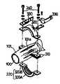
Translated fromKorean제1a도는 종래기술의 케이블 클로우저의 일례를 나타내는 부분 분해 사시도.1A is a partially exploded perspective view showing an example of a cable closure of the prior art.
제1b도는 제1a도에 도시된 종래의 케이블 클로우저에 포함되는 케이블파지부재들을 나타내는 확대 분해도.FIG. 1B is an enlarged exploded view showing the cable gripping members included in the conventional cable closer shown in FIG. 1A.
제1c도는 제1a도에 도시된 종래의 케이블 클로우저에 포함되는 단부판을 나타내는 확대분해도.1C is an enlarged exploded view showing an end plate included in the conventional cable closer shown in FIG. 1A.
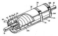
제2도는 본 발명에 따른 케이블 클로우저를 나타내는 부분 절제사시도.2 is a partial ablation perspective view showing a cable closer according to the present invention.
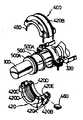
제3도는 제2도에 도시된 본 발명의 케이블 클로우저에 포함되는 단부판을 나타내는 분해사시도.3 is an exploded perspective view showing an end plate included in the cable closure of the present invention shown in FIG.
제4도는 제2도에 도시된 본 발명의 케이블 클로우저에 포함되는 케이블 파지 부재와 단부판을 나타내는 확대측면도.4 is an enlarged side view showing a cable gripping member and an end plate included in the cable closer of the present invention shown in FIG.
제5도는 제4도의 선 A-A를 따라 취한 확대 단면도.FIG. 5 is an enlarged sectional view taken along the line A-A of FIG.
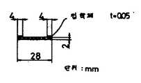
제6a도는 본 발명에 따른 케이블 클로우저에 사용되는 탄성 밀봉 기밀 테이프의 확대단면도.Figure 6a is an enlarged cross-sectional view of an elastic sealing hermetic tape for use in a cable closer according to the present invention.
제6b도는 제6a도에 도시된 동일한 탄성밀봉 기밀테이프의 측면도.6B is a side view of the same elastic sealing hermetic tape shown in FIG. 6A.
제7도는 리일에 감긴 탄성 밀봉 기밀 테이프를 나타내는 도면이다.7 is a diagram showing an elastic sealing hermetic tape wound on a rail.
* 도면의 주요부분에 대한 부호의 설명* Explanation of symbols for the main parts of the drawings
10 : 케이블 20 : 원통형 슬리이브10
22 : 반원통형 슬리이브부재 24 : 슬리이브 체결부재22: semi-cylindrical sleeve member 24: sleeve fastening member
30 : 케이블파지 부재 31 : 나사 지지부재30
32 : 케이블 조임나사 34 : 케이블 압압부재32: cable tightening screw 34: cable pressing member
40 : 단부판 42 : 반환형 단부판부재40: end plate 42: return type end plate member
48 : 비탄성 접착밀봉 테이프물질 50,60 : 탄성기밀테이프48: inelastic adhesive
본 발명은 2개의 통신 케이블 사이에 부여되는 외력(예를 들어, 인장력, 입축력 또는 진동력)과 물로부터 2개의 케이블의 접속점을 보호하기 위한 케이블 클로우져(closure)에 관한 것이다.The present invention relates to a cable closure for protecting the connection points of two cables from water and external forces imparted between two communication cables (e.g., tensile, granular or vibrational forces).
일반적으로, 2개의 통신 케이블들은 케이블 코어(심선)을 노출시키기 위해 케이블로부터 케이블 외피를 제거하고 2개의 노출된 케이블 코어를 연결함으로써 서로 연결된다.In general, the two communication cables are connected to each other by removing the cable sheath from the cable and connecting the two exposed cable cores to expose the cable cores (cores).
이 경우, 물과 외력으로부터 케이블 접속점을 보호하는 것이 필요하기 때문에 기밀(airtight) 구조의 케이블 클로우저가 케이블 접속점에 부착된다.In this case, since it is necessary to protect the cable connection point from water and external force, an airtight cable closer is attached to the cable connection point.
또한, 케이블과 케이블 클로우저는 그의 방수신뢰성을 향상시키기 위해 가압된 가스(예를 들어, 약1기압의 공기, 질소가스 등)로 채워지는 것이 보통이고, 이것이 ″가스 보수″(gas maintenance)로 불린다. 이 경우, 케이블 클로우저는 그의 내부로부터 외부로 가압된 가스가 누출되는 것을 방지하는 것이 요구된다.In addition, cables and cable closures are usually filled with pressurized gas (eg, about 1 atmosphere of air, nitrogen gas, etc.) to improve their waterproof reliability, which is called ″ gas maintenance ″. . In this case, the cable closer is required to prevent leakage of pressurized gas from the inside to the outside.
또한, 각기다른 직경이 여러 가지 케이블이 있기 때문에, 케이블 클로우저가 여러 가지 직경의 케이블의 어떠한 접속점에도 적용될 수 있어야 하는 것이 요구된다. 또한, 케이블이 옥외에 부설되는 것이 보통이기 때문에, 상기한 기밀성외에 충분한 내구성, 조립 및 분해작업의 용이성, 높은 강도등이 요구된다.In addition, because there are different cables of different diameters, it is required that the cable closure be applicable to any connection point of cables of different diameters. In addition, since the cable is usually laid outdoors, sufficient durability, ease of assembly and disassembly, high strength, and the like are required in addition to the above airtightness.
그러나, 종래기술의 케이블 클로우저에서는, 케이블 접속점이 케이블 외피에 형성된 슬리트(slit)들을 통하여 케이블 코어에 부착된 케이블 파지 부재들에 의해 외력으로부터 보호되고, 케이블, 탄성의 단부판 및 슬리브사이의 공간들내에 배치된 비탄성의 접착 밀봉 테이프 물질에 의해 물로부터 보호되기 때문에, 첫째로, 각기다른 직경의 케이블들에 따라 각종 단부판들이 준비되어야하고, 또한 기밀성을 제공하기 위해 슬리브가 큰 힘으로 탄성의 단부판에 대하여 체결되어야 하며, 조립작업이 어렵게 된다.However, in the prior art cable closers, the cable connection points are protected from external forces by cable gripping members attached to the cable core via slits formed in the cable sheath, and between the cable, the elastic end plates and the sleeves. Since it is protected from water by an inelastic adhesive sealing tape material disposed in the spaces, firstly, various end plates have to be prepared according to cables of different diameters, and the sleeve is elastically elastic to provide tightness. It should be fastened to the end plate of, and the assembling work becomes difficult.
둘째로, 각기다른 직경의 케이블들에 따른 각종 크기의 케이블파지 부재들이 준비되어야 하고 다수의 슬리트가 케이블 외피에 형성되어야 한다.Second, cable gripping members of various sizes according to cables of different diameters must be prepared and a number of slits must be formed in the cable sheath.
셋째로, 비탄성의 접착 밀봉 테이프 물질이 사용되기 때문에, 조립된 비탄성의 접착 밀봉 테이프 물질이 사용되기 때문에, 조립된 케이블 클로우저를 분해하는데 많은 시간이 걸린다. 마지막으로, 비탄성 밀봉 물질의 흐름을 방지하기 위해 밀봉워셔(washer)가 요구되기 때문에, 최종 케이블 클로우저를 조립하는데 많은 수의 구성요소들이 요구되어, 시간이 많이 걸리는 각종 문제점들이 존재한다.Third, because inelastic adhesive sealing tape material is used, it takes a lot of time to disassemble the assembled cable closer because the assembled inelastic adhesive sealing tape material is used. Finally, because a seal washer is required to prevent the flow of inelastic seal material, a large number of components are required to assemble the final cable closure, resulting in a variety of time-consuming problems.
종래기술의 케이블 클로우저의 구성과 그의 단점들에 대해서는 제1a, 제1b 및 제1c도를 참조하여 상세히 후술될 것이다.The construction and disadvantages of the cable closure of the prior art will be described later in detail with reference to FIGS. 1a, 1b and 1c.
따라서, 이들 문제점들을 염두에 두고, 각기다른 직경의 케이블들에의 낮은 적용성, 장시간 기밀성 유지능력의 불충분, 낮은 조립 및 분해작업 효율등과 같은 종래기술의 케이블 클로우저에서의 각종 문제점들을 해결할 수 있는 신규한 케이블 클로우저를 제공하는데 본 발명의 주목적이 있다.Therefore, with these problems in mind, it is possible to solve various problems in the cable closures of the prior art such as low applicability to cables of different diameters, insufficient long-term airtightness, low assembly and disassembly efficiency, and the like. It is a primary object of the present invention to provide a novel cable closer.
상기한 목적을 달성하기 위해, 2개의 케이블들의 접속점을 밀폐하기 위한 본 발명에 따른 케이블 클로우저는, (a) 케이블 접속점을 덮기위한 슬리이브, (b) 케이블과 슬리이브사이 공간을 폐쇄하기 위해 상기 슬리이브의 양 내측단부들에 설치되고, 단단한 물질로 형성된 1쌍의 단부판, (c) 케이블과 상기 단단한 단부판사이간격을 기밀적으로 밀봉하기 위한 제1탄성 밀봉 수단으로 이루어진다.In order to achieve the above object, a cable closure according to the invention for sealing a connection point of two cables comprises: (a) a sleeve for covering the cable connection point, (b) the closing of the space between the cable and the sleeve; A pair of end plates formed on both inner ends of the sleeve and formed of a rigid material, and (c) first elastic sealing means for hermetically sealing the gap between the cable and the rigid end plate.
상기 단부판은 단단한 플라스틱 또는 유리섬유 보강플라스틱으로 만들어진다. 상기 제1탄성 밀봉 수단은 케이블직경에 따라 테이프 감김회수를 조정하게되는 케이블에 감긴 에틸렌 프로필렌 고무의 탄성 기밀 테이프이다.The end plates are made of rigid plastic or fiberglass reinforced plastics. The first elastic sealing means is an elastic airtight tape of ethylene propylene rubber wound on a cable to adjust the number of turns of the tape according to the cable diameter.
또한, 본 발명의 케이블 클로우저는 단부판들에 연결된 슬리이브의 강도에 의해 2개의 케이블들 사이에 부여되는 외력으로부터 케이블 접속점을 보호하도록 단부판과 결합되거나 그 단부판과 일체로 형성된 케이블 파지 수단을 더 포함한다. 여기서 케이블 파지 수단은, (a) 1쌍의 양분가능한 환형나사 지지부재와, (b) 그 환형나사 지지부재의 반경방향으로 이동가능하도록 상기 환형나사 지지부재의 반경방향으로 이동가능하도록 상기 환형나사 지지부재들 각각의 외측 원주를 따라 일정한 각도간격으로 형성된 다수의 나사구성들에 나사결합된 다수의 케이블 조임나사와, (c) 각각의 내측 표면에 원추형 또는 삼각형 돌기들을 가지며, 상기 케이블 조임나사들이 반경방향 내측으로 이동된때 케이블 파지를 위해 상기 원추형 또는 삼각형 돌기들이 케이블 외피에 단단하게 접촉되도록 상기 케이블 조임나사의 반경방향 내측 단부에 헐겁게 설치된 다수의 궁형 케이블 압력부재로 이루어진다.In addition, the cable closure of the present invention provides a cable gripping means coupled to or integrally formed with the end plate to protect the cable connection point from external forces imparted between the two cables by the strength of the sleeve connected to the end plates. It includes more. Wherein the cable gripping means comprises: (a) a pair of bisectable annular screw support members; A plurality of cable tightening screws screwed to a plurality of screw configurations formed at regular angular intervals along the outer circumference of each of the support members, and (c) conical or triangular projections on each inner surface thereof. A plurality of arcuate cable pressure members are loosely installed at the radially inner end of the cable tension screw such that the conical or triangular projections are in firm contact with the cable sheath for cable gripping when moved radially inward.
또한, 슬리이브는 버클(buckle)을 각각 구비한 다수의 슬리이브 체결밴드에 의해 체결된 양분가능한 원통형 슬리이브 부재이다.The sleeve is also a bisectable cylindrical sleeve member fastened by a plurality of sleeve fastening bands each provided with a buckle.
종래기술의 케이블 클로우저보다 우수한 본 발명에 따른 케이블 클로우저의 특징 및 이점들은 첨부도면과 관련하여 기술된 본 발명의 바람직한 실시예의 하기 설명으로부터 더 명확하게 인식될 것이다.The features and advantages of the cable closer according to the invention over the cable closure of the prior art will be more clearly recognized from the following description of the preferred embodiment of the invention described in connection with the accompanying drawings.
본 발명의 이해를 용이하게하기 위해 첨부도면을 참조하여 종래기술의 케이블 클로우저를 설명한다.In order to facilitate understanding of the present invention, a prior art cable closure will be described with reference to the accompanying drawings.
제1a, 제1b도 및 제1c도에서, 2개의 케이블(100)이 연결되어있고 케이블 접속점(120)주위에 절연 테이프가 감겨 보호되어 있다. 케이블 클로우저는 대략적으로 양분 가능한 원통형 슬리이브(200), 한조의 케이블 파지부재(300), 및 1쌍의 양분가능한 환형 단부판(400)으로 이루어져 있다.In FIGS. 1A, 1B and 1C, two
슬리이브(200)는 2개의 반원통형 슬리이브 부재들(220)로 분할될 수 있고, 탄력성의 접착 밀봉 테이프 물질(230)을 2개의 플랜지 부분들(220A) 사이에 배치한 채 하나의 슬리이브 부재(220)의 2개의 플랜지 부분들(220A)을 다른 슬리이브 부재(220)의 플랜지 부분들(220A)상에 배치하고 다수의 볼트(240)로 조임으로써 서로 고정될 수 있다.The
케이블 파지부재(300)는 제1b도에 도시된 바와 같이, 케이블 외피(101)에 형성된 슬리트(101a)를 통하여 케이블 코어(도시되지 않음)와 케이블 외피(101) 사이 공간내로 삽입되는 한쌍의 내측 반원형 부재들(310)과, 케이블 외피(101)의 외측 원주표면에 결합되는 한쌍의 외측 반원형 부재들(320)과, 한쌍의 연결봉들(330)로 이루어져 있다.The
제1b도에는 상기 내측 반원형 부재들(310)의 평편한 부분들만이 도시되어 있다. 외측 반원형 부재들(320) 각각은 내측부재(320A)와 외측부재(320B)로 이루어져 있다.Only flat portions of the inner
상기한 3가지 부재들, 즉, 내측 반원형 부재(310), 외측 반원형 부재(320) 및 연결봉(330)은 다수의 볼트(340)에 의해 동시에 서로 고정되어, 연결봉(330)의 강도에 의해, 2개의 케이블(100) 사이에 부여되는 외력으로부터 케이블 접속점(120)을 보호하도록 한다.The three members, that is, the inner
단부판(400)은 2개의 반환형 단부판 부재들(420)로 분할될 수 있다. 제1c도에 도시된 바와 같이, 탄성물질(고무)로 만들어진 각 반환형 단부판 부재(420)에는, 한쌍의 반원형 플랜지 부분들(420A)과, 그 2개의 플랜지 부분들(420A) 사이에 형성된 외측 반원형 홈부분(420B)과, 내측 반원형 홈부분(420C)과, 2개의 내측워셔 보유부분들(420D), 및 2개의 평편한 표면 홈부분들(420E)이 형성되어 있다. 이들 2개의 반환형 단부판 부재들(420)은 그 2개의 단부판 부재들의 2개의 평편한 표면 홈부분들(420E) 사이에 비탄성의 접착 밀봉 테이프 물질(480)을 배치한 채 4개의 볼트(450)로 서로 고정된다.
상기한 바와 같은 케이블 클로우저의 조립에 있어서는, 2개의 단부들(400)이 고정되는 2곳의 위치에서 케이블 외피의 외측 원주표면에 비탄성 접착 밀봉 테이프 물질(500)이 부착된다. 이 경우, 탄성물질(고무)로 만들어진 2개의 밀봉물질 지지워셔(500A)가 상기 밀봉 테이프 물질(500)이 소정위치로부터 미끄러져 이탈하는 것을 방지하기 위해 제1c도에 도시된 바와 같이 케이블(100)에 설치된다.In assembling the cable closer as described above, inelastic adhesive sealing
반환형 단부판 부재들(420)의 2개의 평편한 표면 홈부분(420E)에 접착 밀봉 테이프 물질(480)을 배치하고 밀봉물질 지지워셔(500A)의 외측 원주표면을 상기 단부판 부재들의 케이블 워셔 보유부분들(420D)의 내측 원주표면과 결합시키고 2개의 반환형 단부판 부재들(420) 사이에 접착 밀봉 테이프 물질(500)을 배치한 채 2개의 반환형 단부판 부재들(420)이 4개의 볼트(450)에 의해 서로 고정된다.Placing the adhesive
그후, 유사한 비탄성 접착 밀봉 테이프 물질(600)이 2개의 고정된 단부판 부재들(420)의 외측 반원형 홈부분(420B)에 부착된다. 또한, 2개의 반원통형 슬리이브 부재(220)가 상기 밀봉 테이프 물질(600)(또는, 단부판(420)의 2개의 플랜지부분(420A))을 슬리이브 부재(220)의 내측단부 원주표면에 형성된 홈부분(220B)에 결합시킨 후 볼트(240)에 의해 서로 고정된다. 이 경우, 2개의 밀봉부재(230)가 2개의 슬리이브 부재들(220)의 2개의 플랜지 부분들(220A) 사이에 배치된다.A similar inelastic adhesive
전술한 종래기술의 케이블 클로우저에서, 케이블 접속점(120)은 2개의 단부판(400)과 슬리이브(200)에 의해 덮힌다. 케이블(100)과 단부판(400) 사이의 기밀성이 케이블(100) 주위에서 2개의 밀봉물질 고무 지지워셔(500A) 사이에 부착된 비탄성 접착 밀봉 테이프 물질(500)에 의해 얻어질 수 있다.In the cable closure of the prior art described above, the
여기서, 2개의 고무 지지워셔(500A)는 밀봉 테이프 물질(500)을 지지하도록만 작용할 뿐 기밀부재로 작용하지는 않는다. 단부판(400)과 슬리이브(200) 사이의 기밀성은 단부판(400) 주위에 부착된 유사한 비탄성 접착 밀봉 테이프 물질(600)에 의해 얻어질 수 있다. 2개의 반환형 단부판 부재들(420) 사이의 기밀성은 단부판 부재들(420)의 2개의 평편한 표면 홈부분들(420E)에 부착된 2개의 비탄성 접착 밀봉 테이프 물질(480)에 의해 얻어질 수 있다. 또한, 2개의 반원통형 슬리이브 부재들(220) 사이의 기밀성은 탄성의 접착 밀봉 테이프 물질(230)에 의해 얻어질 수 있다.Here, the two
요약하면, 종래기술의 케이블 클로우저에서는 케이블 클로우저의 기밀성을 얻기위해 비탄성의 접착 밀봉 테이프 물질이 사용된다. 또한, 케이블 접속점(120)은 케이블파지부재들(300)의 연결봉(330)에 의해, 2개의 케이블(100) 사이에 부여되는 외력에 대하여 보강된다.In summary, in the prior art cable closers, an inelastic adhesive sealing tape material is used to obtain the airtightness of the cable closure. In addition, the
그러나, 종래기술의 케이블 클로우저에서는 하기와 같은 각종 문제점들이 존재한다.However, the following various problems exist in the cable closure of the prior art.
(1) 높은 비용(1) high cost
(a) 내측 반원형 부재(310)와 외측 반원형 부재(320)로 이루어진 케이블 파지부재(300)가 케이블(100)에 설치되어야 하기 때문에, 각기다른 직경의 각종 케이블들에 따라 각기다른 크기의 많은 종류의 케이블 파지부재(300)를 사전에 준비하는 것이 필요하였다.(a) Since the
(b) 케이블(100)과 단부판(400)사이 공간이 비탄성의 접착 밀봉물질(500)에 의해 밀봉되기 때문에, 케이블(100) 주위에 제공될 접착 밀봉물질의 양이 필연적으로 제한된다. 따라서, 각기다른 직경의 각종 케이블들에 따라 많은 종류의 단부판(400)과 밀봉워셔(500A)를 사전에 준비하는 것이 필요하였다. 그렇지 않으면, 단부판(400)의 내측 반원형 중공부분이 공사현장에서 특수한 공구에 의해 케이블의 크기에 따라 조정되어야 하며, 또한 단부판(400)의 길이방향 두께가 기밀성을 얻는데 충분히 두껍게 만들어져야 한다.(b) Since the space between the
(2) 긴 조립시간(2) long assembly time
(a) 케이블 코어와 케이블 외피사이로 내측 반원형 부재(310)를 삽입하기 전에 4 또는 6개의 슬리트(101a)가 케이블 외피(101)에 형성되어야 하기 때문에, 비교적 긴 조립시간이 요구된다.(a) Since four or six slits 101a must be formed in the
(b) 케이블(100)과 단부판(400) 사이의 기밀성과 단부판(400)과 슬리이브(200) 사이의 기밀성이 비탄성의 접착 밀봉 테이프 물질(500) 및 (600)에 의해 유지되기 때문에, 단부판(400)이 탄성물질(고무)로 만들어져야 한다.(b) Because the airtightness between the
이 경우, 단부판(400)이 단부판 볼트들(450)에 의해 건고하게 조여질지라도, 그 단부판(400)이 부분적 또는 국부적으로 변형되기 때문에 그 단부판의 원주방향에 걸쳐 균일하게 그의 반경방향 내측방향으로 그 단부판(400)을 압축시키기 위해 2개의 슬리이브 부재(220)를 슬리이브 볼트들(240)로 견고하게 조이는 것이 필요하였다. 따라서, 180kg-cm만큼 큰 토오크를 각 볼트(240)에 부여함에 의해 많은 슬리이브 볼트들(240)이 조여졌고, 그리하여 맨홀내와 같은 비교적 작은 작업공간 내에서 조립작업하는 것이 어려웠다.In this case, even if the
상기한 문제들은 종래기술의 케이블 클로우저에서는 기밀성이 주로 접착 테이프의 접착력에 좌우된다는 사실에 기인한다.The above problems are due to the fact that in the cable closure of the prior art, the airtightness mainly depends on the adhesive force of the adhesive tape.
(3) 기타 다른 문제점(3) other problems
(a) 케이블 접속점이 연결봉(330)에 의해 보강되고 더욱이 슬리트들(101a)이 케이블 외피(101)에 형성되기 때문에, 케이블(100)을 저장할 수 있는 케이블 클로우저내의 내구공간이 감소된다.(a) Since the cable connection point is reinforced by the connecting
(b) 접착밀봉 물질이 케이블 클로우저의 기밀성을 제공하기 위해 사용되기 때문에, 케이블들이 재연결될 필요가 있는 경우에는 케이블 클로우저를 분해하는데 많은 시간이 요구된다.(b) Since adhesive sealing material is used to provide airtightness of the cable closure, much time is required to disassemble the cable closure if the cables need to be reconnected.
상기 설명을 고려하여, 본 발명에 따른 케이블 클로우저의 일실시예를 설명하면 다음과 같다.In consideration of the above description, an embodiment of a cable closer according to the present invention will be described.
본 발명의 케이블 클로우저의 특징은 각기다른 직경의 어떠한 케이블에도 적용될 수 있도록 단단한(예를 들어, 플라스틱) 단부판과 탄성(고무), 기밀부재들에 의하여 케이블과 단부판들 사이 그리고 그 단부판들과 슬리이브사이의 기밀성을 얻는데 있다.A feature of the cable closure of the present invention is that between the cable and the end plates and their end plates by means of rigid (e.g. plastic) end plates and elastic (rubber), hermetic members so that they can be applied to any cable of different diameters. Is to gain the confidentiality between the and the sleeve.
또한, 본 발명의 또 다른 특징은 슬리이브에 의해 케이블 접속점의 강도를 보강하도록, 어떠한 연결봉의 사용없이 각 단부판에 결합되는 간단한 케이블 파지부재를 제공하는데 있다.It is a further feature of the present invention to provide a simple cable gripping member which is coupled to each end plate without the use of any connecting rods to reinforce the strength of the cable connection points by the sleeve.
본 발명의 케이블 클로우저는 대략적으로, 양분가능한 원통형 슬리이브(20), 3개의 케이블 조임나사를 포함하는 한쌍의 환형 케이블 파지부재(30), 및 한쌍의 양분가능한 환형 단부판(40)으로 이루어져 있다. 그 환형 단부판(40)은 예를 들어 3개 또는 그 이상의 판들로 분할될 수 있다.The cable closer of the present invention is roughly composed of a bisectable
제2도에서, 슬리이브(20)는 2개의 반원통형 슬리이브 부재들(22)로 분할될 수 있고, 다수의 슬리이브 체결부재들(24)(이 체결 부재들 각각은 금속밴드(24A)와 버클(24B)로 이루어짐.)에 의해 서로 고정된다. 이들 슬리이브 체결부재(24)는 슬리이브(20)의 길이방향을 따라 일정한 간격으로 배열된다. 또한, 2개의 탄성(고무) 밀봉부재(23)가 2개의 슬리이브 부재들(22)이 서로 고정될 때 각 슬리이브 부재(22)의 2개의 단부면들(22A) 사이에 배치되어 그들 사이의 기밀성을 제공하도록 한다. 또한, 각 슬리이브부재(22)에는 단부판들(40)과 결합될 수 있는 2개의 내측단부 홈부분(22B)이 형성되어 있다.In FIG. 2, the
본 발명의 슬리이브(20)의 특징은 제1a도에 도시된 종래기술의 슬리이브에서와 같은 플랜지부분들을 가지고 있지 않다는 것이다. 이것은 슬리이브(20)에 의해 단부판들(40)을 강하게 조일 필요가 없기 때문이다. 따라서, 슬리이브(20)의 형상이 극소화되고 단순하게 될 수 있다.A feature of the
제4 및 5도에서, 케이블 파지부재(30)는 양분 가능한 환형의 나사 지지부재(31)와, 다수(예를 들어, 3개의 케이블 조임나사(32)와, 다수의 궁형케이블 압력부재(34)로 이루어져 있다. 상기 케이블 압력부재들(34) 각각은 그의 반경방향 내측 표면에 다수의 원추형 돌기들(34a)을 가지고 있다. 양분가능한 환형나사 지지부재(31)는 대직경부분(31a)과 소직경부분(31b)을 가지고 있고, 대직경부분의 원주 표면을 따라 케이블 조임나사들(32)이 일정한 각도간격으로 배열되어 있고, 상기 소직경부분은 단부판(40)과 결합가능한 홈부분을 가지고 있다. 궁형의 케이블 압력부재(34)는 케이블 조임나사(32)의 최내측단부에 회전 가능하게 부착되어 있다. 움직일 수 있는 케이블 압력부재(34)를 구비한 상기 케이블 조임나사(32)는 환형나사 지지부재(31)의 내측으로부터 그 나사 지지부재의 원주표면에 형성된 나사구멍(31c)에 나사결합된다.4 and 5, the
조립에 있어서는, 2개의 반환형 나사 지지부재들(31)이 그 지지부재들 사이에 케이블(10)을 배치한 채 볼트(33)에 의해 서로 고정된다. 그후, 3개의 케이블 조임나사(32)가 케이블(10)쪽 반경방향 내측으로 균일하게 조여져, 3개의 궁형 케이블 압력부재(34)가 케이블 파지를 위해 균일하게 케이블 외피(11)의 외측 원주와 접촉될 수 있도록 한다. 궁형 케이블 압력부재(34)의 내측 표면에 형성된 원추형 돌기들(34a)이 케이블 외피를 침투하기 때문에, 케이블(10)이 케이블 파지부재(30)에 의해 확고하게 파지된다.In assembly, the two returnable
제3 및 5도에서, 각 단부판(40)은 2개의 반환형 단부판부재들(42)로 분할될 수 있다. 이 실시예에서, 단부판(40)은 (제1도에 도시된 종래기술의 고무단부판(400)과 달리) 플라스틱과 같은 단단한 물질로 만들어진다. 각 단부판부재(42)는 1쌍의 반원형 플랜지부분(42A)과, 그 2개의 플랜지부분(42A)사이에 형성된 외측 반원형 홈부분(42B)과 밀봉부재(50)를 파지하기 위해 내측 반원형 돌기들(42C-1)(제5도)이 형성된 내측 반원형부분(42C)과, 케이블 파지부재(30)와 결합가능한 단부 내측 반원형 홈부분(42D) 및 2개의 평편한 표면 홈부분(42E)을 가지고 있다.In FIGS. 3 and 5, each
상기한 주요 구성요소들의 밀봉방법을 설명하면 다음과 같다.Referring to the sealing method of the above main components are as follows.
케이블(10)과 단부판(40)을 밀봉하기 위해, 탄성(고무) 기밀 테이프(50)를 제3도에 도시된 바와 같이 케이블(10) 주위에 2 또는 3회 감는다. 그러나, 이 기밀 테이프의 감는 회수는 케이블의 직경에 따라 조정될 수 있다. 동일한 방식으로, 단부판(40)과 슬리이브(20)를 밀봉하기 위해, 탄성 기밀 테이프(60)(상기한 기밀 테이프(50)와 유사한)를 제5도에 도시된 바와 같이 단부판 부재(42)의 외측 반원형 홈부분(42B)에 감는다.In order to seal the
2개의 단부판부재(42)를 밀봉하기 위해, 비탄성의 접착 밀봉 테이프 물질(48)을 2개의 단부판부재(42)의 2개의 평편한 표면 홈부분(42E)사이에 배치한다. 2개의 반원통형 슬리이브 부재(22)를 밀봉하기 위해, 길이 방향 가스켓 스트립, 즉, 탄성 밀봉부재(23)를 2개의 슬리이브 부재(22)의 2개의 단부면(22A)사이에 배치한다.In order to seal the two
상기한 기밀 고무 테이프로서는, JIS(일본 공업규격)에 표준화된 A-타입 스프링 경도 테스터로 측정한때 대략 55도의 경도를 가지는 EPDM(에틸렌프로필렌 디엔메틸렌)으로 불리는 에틸렌프로필렌 고무를 사용하는 것이 바람직하다. 이 시험방법에서는, 몇 개(6개 이상)의 고무 테이프들을 쌓아 두께가 12mm이상인 시험샘플을 얻고, 경도테스터의 시험표면이 그 시험샘플의 표면과 접촉되게 하여, 시험바늘(스프링 하중(1000gf 또는 9.81N)에 의해 밀어붙혀지고, 시험표면에 형성된 구멍을 통하여 돌출함.) 이 시험고무 샘플의 탄성력에 의해 되밀리는 거리(도)를 측정한다.As the above airtight rubber tape, it is preferable to use ethylene propylene rubber called EPDM (ethylene propylene diemethylene) having a hardness of approximately 55 degrees as measured by an A-type spring hardness tester standardized to JIS (Japanese Industrial Standard). In this test method, several (6 or more) rubber tapes are stacked to obtain a test sample having a thickness of 12 mm or more, and the test surface of the hardness tester is brought into contact with the surface of the test sample, and the test needle (spring load (1000 gf or 9.81 N) and protrudes through a hole formed in the test surface.) Measure the distance (degrees) backed by the elastic force of this test rubber sample.
제6a도 및 제6b도는 기밀 테이프의 칫수의 실시예를 나타낸다. 제6a도에서 그 테이프의 두께는 약 2mm이고 폭은 약 28mm이다. 또한, 테이프 감는 작업을 용이하게 하기 위해 기밀 테이프의 일표면의 양측단에 접착제(폭이 4mm이고, 두께가 0.05mm임.)를 부착하는 것이 특히 바람직하다.(그 때문에 테이프가 풀리는 것을 방지하기 위해 손으로 그 테이프를 잡는 것이 불필요하다.) 또한, 기밀 테이프의 전체 길이는 제6b도에 도시된 바와 같이 약 2600mm이고, 제7도에 도시된 바와 같이 2개의 테이프사이에 분리종이가 배치된채 리일에 감겨있다. 그 기밀 테이프는 그 테이프로부터 분리종이를 제거한 후 케이블(10)에 감긴다.6A and 6B show an embodiment of the dimensions of an airtight tape. In Figure 6a the tape is about 2 mm thick and about 28 mm wide. In addition, it is particularly preferable to attach an adhesive (a width of 4 mm and a thickness of 0.05 mm) to both ends of one surface of the airtight tape in order to facilitate the tape winding operation. It is also unnecessary to hold the tape by hand.) In addition, the total length of the airtight tape is about 2600 mm as shown in FIG. 6B, and a separation paper is disposed between the two tapes as shown in FIG. It is wound around the rail. The hermetic tape is wound around the
본 발명의 케이블 클로우지의 조립과정을 설명하면 다음과 같다.Referring to the assembly process of the cable closet of the present invention.
먼저, 2개의 케이블 파지부재(30)를 케이블 접속점(12)의 양측에서 서로로부터 소정거리만큼 떨어져 있는 2개의 위치에서 케이블(10)에 고정시킨다. 즉, 각 케이블 파지부재(30)를 2개의 반환형 나사 지지부재들(31)로 분리시키고, 2개의 나사 지지부재(31)에 의해 형성된 중앙의 중공부분을 통하여 케이블(10)을 통과시킨 후 볼트들(33)로 고정시킨다. 그후, 3개의 케이블 조임나사(32)를 나사 돌리개로 조인다. 그 나사돌리개의 토오크는 각 궁형 케이블 압력부재(34)가 케이블 외피와 견고하게 접촉하도록 하는 원하는 어떤 값으로 결정될 수 있다.First, the two
이들 상태에서, 케이블 압력부재(34)의 원추형 돌기들(34a)이 케이블 외피를 침투하기 때문에 케이블 압력부재(34)가 케이블을 확고하게 파지하는 것이 가능하다.In these states, it is possible for the
탄성(고무) 기밀 테이프(50)를 제3도에 도시된 바와 같이 2개의 고정된 케이블파지부재(30) 가까이에서 케이블(10) 주위에 감는다. 이 경우, 그 기밀 테이프(50)의 감는 회수는 케이블 직경을 고려하여 결정된다.An elastic (rubber)
그후, 각 단부판(40)을 2개의 반환형 단부판부재(42)로 분리시키고, 2개의 단부판 부재들(42)사이에 상기 감긴 기밀 테이프(50)를 배치하고 단부판 부재들(42)의 2개의 평편한 표면 홈부분들(42E)사이에 밀봉부재(비탄성의 밀봉물질)(48)를 배치한 채 볼트들(45)로 조인다. 또한, 2개의 단부판 부재들(42)이 서로 고정된 때, 단부판 부재들(42)의 내측 반원형 홈부분(42D)이 케이블 파지부재(30)의 소직경부분(31b)과 결합된다.Then, each
탄성(고무) 기밀 테이프(60)를 소정회수만큼 단부판(40)의 외측 홈부분(42B)주위에 감는다.The elastic (rubber)
슬리이브(20)를 2개의 반원통형 슬리이브 부재(22)로 분리시키고, 2개의 단부판(40)의 외측 원주부분들(즉, 기밀 테이프(60)가 슬리이브 부재(22)에 형성된 2개의 내측단부 홈부분들(22B)에 맞물린 채 다수의 슬리이브 체결부재(24)로 고정시킨다. 2개의 슬리이브 부재(22)가 서로 고정된 때, 탄성 밀봉부재, 즉, 가스켓스트립(23)을 2개의 슬리이브 부재들(22) 각각의 2개의 단부면(22A)에 부착한다.The
이러한 조립상태하에서 2개의 케이블 파지부재(30)가 2개의 단단한 단부판(40)을 통하여 슬리이브(20)에 연결되기 때문에 슬리이브(20)의 강도에 의해, 2개의 케이블들 사이에 부여되는 외력으로부터 케이블 접속점(12)을 보호하는 것이 가능하다. 더욱이, 케이블(10)과 단부판(40)사이의 기밀성이 기밀 테이프에 의해 유지되고 단부판들(40) 사이의 기밀성이 접착 밀봉물질에 의해 얻어지고, 슬리이브(20)와 단부판(40)사이의 기밀성이 첫 번째 언급된 기밀 테이프와 동일재료이지만 다른 형태를 가지는 다른 기밀 테이프에 의해 유지되며, 슬리이브들(20) 사이의 기밀성이 길이방향 가스켓 스트립(23)에 의해 제공되기 때문에, 물로부터 케이블 접속점(12)을 보호하거나 또는 내부의 가압된 가스가 외부로 누출되는 것을 방지하는 것이 가능하다.Under this assembly, the strength of the
상기한 실시예에서, 기밀성의 관점에서 단부판(40)과 슬리이브(20)를 동일재료로 형성하는 것이 바람직한데, 그 이유는 단부판(40)과 슬리이브(20)사이에 팽창율 및 수축율의 차이가 존재하지 않기 때문이다.In the above embodiment, it is preferable to form the
또한, 케이블 파지부재(30)가 단부판(40)과 별도로 제공될지라도, 나사 지지부재(31)를 단부판부재(42)와 일체로 형성하는 것이 바람직하다.Further, although the
또한, 환경에 따른 외력으로부터 케이블 접속점을 보호하기 위해 단부판에 큰 기계적 강도가 요구될 때, 단부판을 유리섬유로 보강된 플라스틱 물질로 형성하거나 또는 단부판에 리브(rib)를 제공하는 것이 바람직하다.In addition, when a large mechanical strength is required on the end plates to protect the cable connection points from external forces according to the environment, it is desirable to form the end plates from glass fiber reinforced plastic material or to provide ribs in the end plates. Do.
전술한 바와 같은 본 발명에 따른 케이블 클로우저는 다음과 같은 각종 이점들을 가진다.The cable closer according to the present invention as described above has various advantages as follows.
(a) 케이블(10)과 단부판(40)사이의 기밀성이 탄성의 기밀 테이프(50)를 감는 것에 의해 얻어질 수 있기 때문에, 케이블(10)과 단부판(40)의 내측 원주표면과의 사이의 간격이 케이블 직경의 변화에 따라 변할지라도, 그 간격을 기밀 테이프(50)로 조절가능하게 채우는 것이 가능하여, 케이블 직경에 따른 각종 크기의 단부판(40)을 준비할 필요가 없게 된다. 또한, 종래기술의 밀봉위셔(500A)로 제거하는 것이 가능하며, 그이 비용을 감소시킬 수 있게 된다.(a) Since the airtightness between the
(b) 케이블 파지부재(30)가 그의 반경방향으로 케이블 조임나사(32)를 조정가능하게 이동시킴으로써 케이블 외피를 파지할 수 있기 때문에, 부품의 수를 크게 감소시킬 수 있고, 케이블 직경에 따른 각종 크기의 케이블 파지부재를 준비할 필요성을 제거할 수 있다. 또한, 케이블 외피에 슬리트를 형성할 필요가 없어 그의 비용 및 조립시간을 감소시킬 수 있게된다.(b) Since the
(c) 케이블(10)과 단부판(40)사이의 기밀성과 단부판(40)과 슬리이브(20) 사이의 기밀성이 각각 탄성의 밀봉 물질에 의해 얻어질 수 있기 때문에, 슬리이브 체결력을 180kg-cm(종래기술)로부터 70kg-cm(본 발명)로 크게 감소시킬 수 있다.(c) Since the airtightness between the
(d) 따라서, 플랜지부분(종래기술에서와 같은)을 제공함이 없이 볼트대신 다수의 밴드(24)로 슬리이브(20)를 체결하는 것이 가능하여, 슬리이브 크기를 최소화할 수 있고 조립작업을 용이하게 할 수 있다.(d) Thus, it is possible to fasten the
(e) 케이블 파지부재(30), 단부판(40) 및 슬리이브(20)가 서로 일체로 고정되기 때문에, 연결봉(종래기술에서와 같은)을 제거할 수 있어 케이블 클로우저내의 내부공간을 증대시킬 수 있다.(e) Since the
(f) 기밀성을 얻기위해 접착 밀봉 물질이 사용되지 않기 때문에, 분해작업을 용이하게 할 수 있다.(f) Since adhesive sealing materials are not used to achieve airtightness, the disassembly can be facilitated.
상기한 바와 같이, 본 발명에 따른 케이블 클로우져에서는, 각종 구성요소들 사이의 기밀성이 고무 기밀 테이프를 조정가능하게 제공함으로써 얻어질 수 있기 때문에, 미리 정해진 크기의 단일의 단부판이 각기다른 직경의 각종 케이블들에 적용될 수 있다. 또한, 케이블이 케이블 조임나사를 돌리는 것에 의해 간단히 파지되고, 단부판을 통하여 케이블 파지 수단에 연결된 슬리이브에 의해 보강될 수 있기 때문에, 케이블 파지 요소들의 수를 감소시키고, 조립작업을 용이하게 할 수 있다.As described above, in the cable closure according to the present invention, since the airtightness between the various components can be obtained by adjustablely providing the rubber airtight tape, a single end plate of a predetermined size can be used for various diameters of different diameters. It can be applied to cables. In addition, since the cable can be simply gripped by turning the cable tightening screw and reinforced by a sleeve connected to the cable gripping means through the end plate, the number of cable gripping elements can be reduced and the assembly work can be facilitated. have.
실제로, 제1도에 도시된 종래기술의 케이블 클로우저와 비교하여 조립시간을 약 40-50%만큼, 그리고 장치비용을 약 25-35%만큼 감소시키는 것이 가능하다.Indeed, it is possible to reduce the assembly time by about 40-50% and the device cost by about 25-35% compared to the cable closure of the prior art shown in FIG.
Claims (8)
Translated fromKoreanApplications Claiming Priority (7)
| Application Number | Priority Date | Filing Date | Title |
|---|---|---|---|
| JP?62-289,388 | 1987-11-18 | ||
| JP62289388AJPH083323B2 (en) | 1987-11-18 | 1987-11-18 | Communication cable jacket grip |
| JPU?63-97384 | 1988-07-25 | ||
| JP1988097384UJPH0222026U (en) | 1988-07-25 | 1988-07-25 | |
| JP??63-97,384 | 1988-07-25 | ||
| JP?63-246,244 | 1988-09-30 | ||
| JP24624488AJPH0667098B2 (en) | 1988-09-30 | 1988-09-30 | Cable connection closure |
Publications (2)
| Publication Number | Publication Date |
|---|---|
| KR890009038A KR890009038A (en) | 1989-07-13 |
| KR910009362B1true KR910009362B1 (en) | 1991-11-12 |
Family
ID=27308390
Family Applications (1)
| Application Number | Title | Priority Date | Filing Date |
|---|---|---|---|
| KR1019880015169AExpiredKR910009362B1 (en) | 1987-11-18 | 1988-11-18 | Cable closure and assembly method |
Country Status (5)
| Country | Link |
|---|---|
| US (1) | US4933512A (en) |
| EP (1) | EP0316911B1 (en) |
| KR (1) | KR910009362B1 (en) |
| CA (1) | CA1318948C (en) |
| DE (1) | DE3850047T2 (en) |
Cited By (1)
| Publication number | Priority date | Publication date | Assignee | Title |
|---|---|---|---|---|
| KR100387308B1 (en)* | 1994-09-21 | 2003-08-19 | 타이코 일렉트로닉스 레이켐 엔베 | Retention strip |
Families Citing this family (91)
| Publication number | Priority date | Publication date | Assignee | Title |
|---|---|---|---|---|
| DE3941269A1 (en)* | 1989-09-30 | 1991-04-11 | Stewing Kunststoff | CABLE SLEEVE FOR CONNECTING AND BRANCHING CABLES, IN PARTICULAR TELECOMMUNICATION CABLES |
| DE3941268A1 (en)* | 1989-09-30 | 1991-04-11 | Stewing Kunststoff | CABLE SLEEVE FOR CONNECTING AND BRANCHING CABLES, IN PARTICULAR. TELECOMMUNICATION CABLES |
| US5302779A (en)* | 1990-01-24 | 1994-04-12 | Etablissements Morel - Ateliers Electromechaniques De Favieres | Plug for fixing in an impermeable manner an electric cable to an opening and cable protection sleeve comprising such plugs |
| ES2080378T5 (en)* | 1991-06-27 | 2004-01-16 | Ccs Technology, Inc. | CABLE HOSE. |
| US5589666A (en)* | 1991-10-15 | 1996-12-31 | Thomas & Betts Corporation | Enclosure for sealing a splice of electrical cables |
| US5245133A (en)* | 1991-10-15 | 1993-09-14 | Thomas & Betts Corporation | Moisture-resistant cable splice and sealing structure thereof |
| US5251373A (en)* | 1991-10-15 | 1993-10-12 | Thomas & Betts Corporation | Method for protection of cable splices |
| DE4135570C1 (en)* | 1991-10-29 | 1992-11-05 | Stewing Kunststoffbetrieb Gmbh, 4270 Dorsten, De | |
| EP0566090A1 (en)* | 1992-04-14 | 1993-10-20 | Ametek Aerospace Products, Inc. | Repairable cable assembly |
| GB9212624D0 (en)* | 1992-06-15 | 1992-07-29 | Raychem Sa Nv | Cable sealing device |
| US5382756A (en)* | 1993-01-22 | 1995-01-17 | Dagan; Gideon B. | Encapsulation closure for cables |
| US5387763A (en)* | 1993-05-13 | 1995-02-07 | Communications Technology Corporation | Enclosure for straight cable splice |
| US5679927A (en)* | 1993-05-13 | 1997-10-21 | Communications Technology Corporation | Buried service wire closure |
| DE4333067C1 (en)* | 1993-09-29 | 1995-03-09 | Rose Walter Gmbh & Co Kg | Device for forming a socket inlet, in particular for fiber optic cables |
| BR9508857A (en)* | 1994-09-21 | 1997-10-21 | Raychem Sa Nv | Cable joint closure |
| GB9419034D0 (en)* | 1994-09-21 | 1994-11-09 | Raychem Sa Nv | Cable sealing |
| GB9419032D0 (en)* | 1994-09-21 | 1994-11-09 | Raychem Sa Nv | Sealing device |
| JP2863124B2 (en) | 1995-01-17 | 1999-03-03 | トーマス アンド ベッツ コーポレーション | Force-enclosed cable connection envelope with encapsulant outflow container |
| US5613298A (en)* | 1995-01-17 | 1997-03-25 | Thomas & Betts Corporation | Forced encapsulation cable splice enclosure |
| US5802715A (en)* | 1995-01-17 | 1998-09-08 | Thomas & Betts Corporation | Method of sealing an elongate cable splice |
| WO1996024185A1 (en)* | 1995-02-02 | 1996-08-08 | N.V. Raychem S.A. | Cable splice closure |
| US5962811A (en)* | 1995-04-28 | 1999-10-05 | Thomas & Betts Corporation | Cable splice enclosure |
| EP0871909B1 (en)* | 1995-09-29 | 2008-05-21 | Minnesota Mining And Manufacturing Company | Fiber optic cable splice closure |
| MY125832A (en)* | 1995-11-06 | 2006-08-30 | Japan Recom Ltd | Closure for cable connection |
| GB9606319D0 (en) | 1996-03-26 | 1996-05-29 | Raychem Sa Nv | Strip for winding around and gripping an elongate object |
| JPH09304631A (en)* | 1996-05-14 | 1997-11-28 | Japan Riicom:Kk | Closure for cable connection |
| SE9602079D0 (en) | 1996-05-29 | 1996-05-29 | Asea Brown Boveri | Rotating electric machines with magnetic circuit for high voltage and a method for manufacturing the same |
| SE510192C2 (en) | 1996-05-29 | 1999-04-26 | Asea Brown Boveri | Procedure and switching arrangements to reduce problems with three-tier currents that may occur in alternator and motor operation of AC machines connected to three-phase distribution or transmission networks |
| ES2208904T3 (en) | 1996-05-29 | 2004-06-16 | Abb Ab | CONDUCTOR FOR HIGH VOLTAGE WINDING AND A ROTARY ELECTRIC MACHINE THAT INCLUDES A WINDING THAT INCLUDES THE DRIVER. |
| JP2000511395A (en) | 1996-05-29 | 2000-08-29 | アセア ブラウン ボベリ アクティエボラーグ | Rotary electrical machine with high voltage stator windings and elongated support for supporting the windings and method of manufacturing such a machine |
| CN1220039A (en) | 1996-05-29 | 1999-06-16 | Abb阿西亚布朗·勃法瑞公司 | Insulated conductor for high voltage winding and method of making same |
| CN1101988C (en) | 1996-05-29 | 2003-02-19 | Abb股份公司 | Electric high voltage AC machine |
| CA2256469A1 (en) | 1996-05-29 | 1997-12-04 | Abb Ab | Transformer/reactor |
| FR2749712B1 (en)* | 1996-06-05 | 1998-08-14 | Pouyet Sa | DEVICE FOR MOUNTING AT LEAST ONE CABLE IN A DISC TO BE POSITIONED IN A SLEEVE FOR PROTECTING A CABLE CONNECTION |
| SE510422C2 (en) | 1996-11-04 | 1999-05-25 | Asea Brown Boveri | Magnetic sheet metal core for electric machines |
| SE509072C2 (en) | 1996-11-04 | 1998-11-30 | Asea Brown Boveri | Anode, anodizing process, anodized wire and use of such wire in an electrical device |
| SE515843C2 (en) | 1996-11-04 | 2001-10-15 | Abb Ab | Axial cooling of rotor |
| SE512917C2 (en) | 1996-11-04 | 2000-06-05 | Abb Ab | Method, apparatus and cable guide for winding an electric machine |
| SE9704431D0 (en) | 1997-02-03 | 1997-11-28 | Asea Brown Boveri | Power control of synchronous machine |
| SE9704424D0 (en)* | 1997-02-03 | 1997-11-28 | Asea Brown Boveri | Device for cable joints and rotating electric machine comprising the device |
| SE9704427D0 (en) | 1997-02-03 | 1997-11-28 | Asea Brown Boveri | Fastening device for electric rotary machines |
| SE508544C2 (en) | 1997-02-03 | 1998-10-12 | Asea Brown Boveri | Method and apparatus for mounting a stator winding consisting of a cable. |
| SE9704422D0 (en) | 1997-02-03 | 1997-11-28 | Asea Brown Boveri | End plate |
| SE9704413D0 (en) | 1997-02-03 | 1997-11-28 | Asea Brown Boveri | A power transformer / reactor |
| SE9704421D0 (en) | 1997-02-03 | 1997-11-28 | Asea Brown Boveri | Series compensation of electric alternator |
| SE510452C2 (en) | 1997-02-03 | 1999-05-25 | Asea Brown Boveri | Transformer with voltage regulator |
| SE9704412D0 (en) | 1997-02-03 | 1997-11-28 | Asea Brown Boveri | A power transformer / reactor |
| SE508543C2 (en) | 1997-02-03 | 1998-10-12 | Asea Brown Boveri | Coiling |
| SE9704423D0 (en) | 1997-02-03 | 1997-11-28 | Asea Brown Boveri | Rotary electric machine with flushing support |
| FR2759503B1 (en)* | 1997-02-11 | 1999-04-30 | Japan Recom Ltd | CABLE CONNECTION CLOSING MEMBER |
| ES2129350B1 (en)* | 1997-02-11 | 2000-01-01 | Japan Recom Ltd | LOCK FOR CABLE CONNECTION. |
| SE513083C2 (en) | 1997-09-30 | 2000-07-03 | Abb Ab | Synchronous compensator system and the use of such and phase compensation method in a high voltage field |
| US6037544A (en)* | 1997-11-22 | 2000-03-14 | Lg Chemical Ltd | Splice closure for telecommunications cables |
| SE513555C2 (en) | 1997-11-27 | 2000-10-02 | Abb Ab | Method of applying a pipe means in a space of a rotating electric machine and rotating electric machine according to the method |
| BR9815420A (en) | 1997-11-28 | 2001-07-17 | Abb Ab | Method and device for controlling the magnetic flux with an auxiliary winding on a rotating high voltage alternating current machine |
| GB2331853A (en) | 1997-11-28 | 1999-06-02 | Asea Brown Boveri | Transformer |
| GB2331867A (en) | 1997-11-28 | 1999-06-02 | Asea Brown Boveri | Power cable termination |
| GB2331858A (en) | 1997-11-28 | 1999-06-02 | Asea Brown Boveri | A wind power plant |
| RU2201026C2 (en)* | 1997-12-09 | 2003-03-20 | Дсг-Кануза Гмбх Унд Ко.Кг | Device for holding and guiding elongated objects |
| EP0923178A3 (en) | 1997-12-09 | 2001-01-03 | RXS Kabelgarnituren Gesellschaft mit beschränkter Haftung | Cable sleeve, comprising a tubular sleeve and at least a transversely split frontal sealing body |
| US6801421B1 (en) | 1998-09-29 | 2004-10-05 | Abb Ab | Switchable flux control for high power static electromagnetic devices |
| US6242700B1 (en) | 1999-01-27 | 2001-06-05 | 3M Innovative Properties Company | End seal assembly for a splice case |
| US6294737B1 (en) | 1999-06-23 | 2001-09-25 | P. L. Chestney | Reusable closure for wire splices |
| US6378202B1 (en)* | 1999-06-29 | 2002-04-30 | Sbc Communications | Thermal shield and hermetic seal for preventing deterioration of plastic insulation in open access closures and method therefor |
| DE19958982C2 (en)* | 1999-11-24 | 2002-06-13 | Hoehne Gmbh | sleeve |
| SE516002C2 (en) | 2000-03-01 | 2001-11-05 | Abb Ab | Rotary electric machine and method of making a stator winding |
| US6885273B2 (en) | 2000-03-30 | 2005-04-26 | Abb Ab | Induction devices with distributed air gaps |
| SE516442C2 (en) | 2000-04-28 | 2002-01-15 | Abb Ab | Stationary induction machine and cable therefore |
| JP2003038417A (en) | 2001-07-27 | 2003-02-12 | Olympus Optical Co Ltd | Endoscopy system |
| US6872891B2 (en)* | 2002-10-30 | 2005-03-29 | Dallas Angele | Cable splice case expansion ring and system for splicing cable |
| GB0314688D0 (en)* | 2003-06-24 | 2003-07-30 | Tyco Electronics Raychem Nv | Cable splice closure |
| SE527377C2 (en) | 2004-06-03 | 2006-02-21 | Volvo Lastvagnar Ab | Wiring protection and method of mounting a wiring protection |
| KR100678396B1 (en)* | 2004-06-18 | 2007-02-02 | 박재형 | Sleeve cover |
| US7094972B2 (en)* | 2004-07-13 | 2006-08-22 | Thomas & Betts International, Inc. | Insulating cover for electrical connectors |
| US7282644B1 (en)* | 2006-01-17 | 2007-10-16 | Verizon Services Corp. | Aerial cable splice closure |
| US8152559B1 (en) | 2011-03-31 | 2012-04-10 | John Mezzalingua Associates, Inc. | Split compression mid-span ground clamp |
| US8636524B2 (en) | 2011-03-31 | 2014-01-28 | John Mezzalingua Associates, LLC | Split conductive mid-span ground clamp |
| US8152537B1 (en) | 2011-03-31 | 2012-04-10 | John Mezzalingua Associates, Inc. | Split conductive mid-span ground clamp |
| US8366459B2 (en) | 2011-03-31 | 2013-02-05 | John Mezzalingua Associates, Inc. | Compression style mid-span ground clamp |
| US8839594B2 (en)* | 2011-06-29 | 2014-09-23 | Bridgeport Fittings, Inc. | Concrete exclusion structure |
| FR2991114B1 (en)* | 2012-05-25 | 2016-04-01 | Renault Sas | APPARATUS FOR SEALING ELECTRICAL BEAM THROUGH THE OPENING OF A PARTITION. |
| DE202012013316U1 (en)* | 2012-12-18 | 2016-03-11 | Reichle & De-Massari Ag | Kabelkontaktierungswitterungsschutz |
| GB2509775B (en)* | 2013-01-15 | 2018-04-04 | Technetix Bv | Cable Clamp |
| EP2781396A1 (en)* | 2013-03-21 | 2014-09-24 | Delphi International Operations Luxembourg S.à r.l. | Cable connector assembly process, cable connector and set of cable connectors obtained by this process |
| US20160050904A1 (en)* | 2014-08-20 | 2016-02-25 | Gary Earl TURNER, JR. | Utility conduit cover |
| CN105826893B (en)* | 2016-06-20 | 2018-05-08 | 国网新疆电力公司乌鲁木齐供电公司 | A cable insulation explosion-proof box with an observation port |
| CN108054703A (en)* | 2017-12-27 | 2018-05-18 | 上海策元实业有限公司 | A kind of plugging structure for cable hole |
| CN109061243A (en)* | 2018-08-30 | 2018-12-21 | 浙江德清科赛塑料制品有限公司 | Power test seat |
| CN112213825B (en)* | 2019-07-09 | 2022-07-29 | 武汉光卓科技有限公司 | Insulating reinforcing apparatus of fiber optic cable overlap joint |
| KR102699360B1 (en)* | 2019-12-16 | 2024-08-28 | 한국전력공사 | Self-extinguishing cable connector cover |
| JP7400938B2 (en)* | 2020-02-28 | 2023-12-19 | 日本電信電話株式会社 | Fiber optic cable gripping device |
Family Cites Families (17)
| Publication number | Priority date | Publication date | Assignee | Title |
|---|---|---|---|---|
| GB723457A (en)* | 1952-07-07 | 1955-02-09 | Standard Telephones Cables Ltd | Joint for an electric cable |
| US3130259A (en)* | 1962-06-11 | 1964-04-21 | Anaconda Wire & Cable Co | Splice box with cable entrance seals |
| US3233035A (en)* | 1963-10-10 | 1966-02-01 | Sta Crete Inc | Cable splice closure |
| US3614298A (en)* | 1970-02-19 | 1971-10-19 | John T Thompson | Cable splice casing with conductive anchorage to cable sheath and shield |
| US3775204A (en)* | 1971-07-06 | 1973-11-27 | J Thompson | Method of gasketing the mating surface of housing parts and entryways for electrical conductors |
| US3692926A (en)* | 1971-07-06 | 1972-09-19 | Smith Schreyer & Assoc Inc | Alignable end seals for a splice case |
| US3869189A (en)* | 1973-10-03 | 1975-03-04 | Bob C Mccurdy | Underground electrical connector |
| DE2521803B2 (en)* | 1975-05-16 | 1980-04-24 | Felten & Guilleaume Carlswerk Ag, 5000 Koeln | Sleeve for telecommunication cables with strap fastener |
| DE2743937C3 (en)* | 1977-09-29 | 1980-04-24 | Siemens Ag, 1000 Berlin Und 8000 Muenchen | Sealing tape wrap made of permanently plastic sealing compound with support elements for cable fittings |
| US4341922A (en)* | 1979-07-18 | 1982-07-27 | Minnesota Mining And Manufacturing Company | Strain-relief brace for cable splice case |
| US4295005A (en)* | 1979-10-17 | 1981-10-13 | Western Electric Company, Inc. | Cable splice closure |
| YU40773B (en)* | 1980-02-06 | 1986-06-30 | Milenko Maricevic | Universal joint box for telecommunication and energy cables, respectively |
| DE3243828C2 (en)* | 1982-11-26 | 1986-12-04 | Minnesota Mining And Manufacturing Co., Saint Paul, Minn. | Cable connection for telecommunication cables that can be placed under gas pressure |
| US4558174A (en)* | 1984-04-06 | 1985-12-10 | At&T Bell Laboratories | Cable closure |
| US4538021A (en)* | 1984-04-06 | 1985-08-27 | At&T Bell Laboratories, Inc. | Cable closure having asymmetrical end plate assembly |
| FR2582854B1 (en)* | 1985-05-31 | 1988-03-18 | Morel Atel Electromec | SLEEVE FOR PROTECTING CABLE SPLICES AND RELATED METHOD |
| JPH0353561Y2 (en)* | 1985-09-27 | 1991-11-22 |
- 1988
- 1988-11-16CACA000583218Apatent/CA1318948C/ennot_activeExpired - Fee Related
- 1988-11-17DEDE3850047Tpatent/DE3850047T2/ennot_activeExpired - Lifetime
- 1988-11-17USUS07/271,866patent/US4933512A/ennot_activeExpired - Lifetime
- 1988-11-17EPEP88119136Apatent/EP0316911B1/ennot_activeExpired - Lifetime
- 1988-11-18KRKR1019880015169Apatent/KR910009362B1/ennot_activeExpired
Cited By (1)
| Publication number | Priority date | Publication date | Assignee | Title |
|---|---|---|---|---|
| KR100387308B1 (en)* | 1994-09-21 | 2003-08-19 | 타이코 일렉트로닉스 레이켐 엔베 | Retention strip |
Also Published As
| Publication number | Publication date |
|---|---|
| DE3850047T2 (en) | 1994-09-15 |
| CA1318948C (en) | 1993-06-08 |
| EP0316911B1 (en) | 1994-06-08 |
| DE3850047D1 (en) | 1994-07-14 |
| EP0316911A2 (en) | 1989-05-24 |
| KR890009038A (en) | 1989-07-13 |
| US4933512A (en) | 1990-06-12 |
| EP0316911A3 (en) | 1990-10-10 |
Similar Documents
| Publication | Publication Date | Title |
|---|---|---|
| KR910009362B1 (en) | Cable closure and assembly method | |
| US4295005A (en) | Cable splice closure | |
| US5007701A (en) | Splice closure apparatus | |
| US5774618A (en) | Compact closure for optical fiber cable | |
| JP3560090B2 (en) | Closure for cable connection | |
| US20060204198A1 (en) | Cable splice closure | |
| US5235134A (en) | Sealed reenterable splice enclosure | |
| US4181814A (en) | Splice case with gasket and closure mechanism therefor | |
| KR100337568B1 (en) | Cable Sealing Device | |
| KR20010074636A (en) | A seal | |
| JP4119610B2 (en) | Closure seal and closure with seal | |
| US5816746A (en) | Pile wrapper closure assembly and method of installing the same | |
| GB2193605A (en) | Reusable cable joint cover | |
| AU2015200237A1 (en) | Cable gland | |
| US5608189A (en) | Screwable introduction means for sleeves or housings | |
| JP2004341181A (en) | Adapter for thin cable | |
| US12171088B2 (en) | Sealing member | |
| JP3633662B2 (en) | Cable gripper in cable connection closure | |
| KR102604563B1 (en) | Cable gland assembly for easy cable installation | |
| US20070023200A1 (en) | Cable splice closure and method of installation therefor | |
| JPS6389809A (en) | Half-divided type branching connection case | |
| KR200319134Y1 (en) | End closure device for communication or power cable receiving line | |
| JPH0297216A (en) | Cable joint closure | |
| JP3274941B2 (en) | Closure for communication cable | |
| JP2000092688A (en) | Closure for cable connection |
Legal Events
| Date | Code | Title | Description |
|---|---|---|---|
| A201 | Request for examination | ||
| PA0109 | Patent application | St.27 status event code:A-0-1-A10-A12-nap-PA0109 | |
| PA0201 | Request for examination | St.27 status event code:A-1-2-D10-D11-exm-PA0201 | |
| R17-X000 | Change to representative recorded | St.27 status event code:A-3-3-R10-R17-oth-X000 | |
| PG1501 | Laying open of application | St.27 status event code:A-1-1-Q10-Q12-nap-PG1501 | |
| E902 | Notification of reason for refusal | ||
| PE0902 | Notice of grounds for rejection | St.27 status event code:A-1-2-D10-D21-exm-PE0902 | |
| P11-X000 | Amendment of application requested | St.27 status event code:A-2-2-P10-P11-nap-X000 | |
| P13-X000 | Application amended | St.27 status event code:A-2-2-P10-P13-nap-X000 | |
| G160 | Decision to publish patent application | ||
| PG1605 | Publication of application before grant of patent | St.27 status event code:A-2-2-Q10-Q13-nap-PG1605 | |
| E701 | Decision to grant or registration of patent right | ||
| PE0701 | Decision of registration | St.27 status event code:A-1-2-D10-D22-exm-PE0701 | |
| GRNT | Written decision to grant | ||
| PR0701 | Registration of establishment | St.27 status event code:A-2-4-F10-F11-exm-PR0701 | |
| PR1002 | Payment of registration fee | St.27 status event code:A-2-2-U10-U11-oth-PR1002 Fee payment year number:1 | |
| PR1001 | Payment of annual fee | St.27 status event code:A-4-4-U10-U11-oth-PR1001 Fee payment year number:4 | |
| PR1001 | Payment of annual fee | St.27 status event code:A-4-4-U10-U11-oth-PR1001 Fee payment year number:5 | |
| PR1001 | Payment of annual fee | St.27 status event code:A-4-4-U10-U11-oth-PR1001 Fee payment year number:6 | |
| PR1001 | Payment of annual fee | St.27 status event code:A-4-4-U10-U11-oth-PR1001 Fee payment year number:7 | |
| PR1001 | Payment of annual fee | St.27 status event code:A-4-4-U10-U11-oth-PR1001 Fee payment year number:8 | |
| PN2301 | Change of applicant | St.27 status event code:A-5-5-R10-R13-asn-PN2301 St.27 status event code:A-5-5-R10-R11-asn-PN2301 | |
| PR1001 | Payment of annual fee | St.27 status event code:A-4-4-U10-U11-oth-PR1001 Fee payment year number:9 | |
| R18-X000 | Changes to party contact information recorded | St.27 status event code:A-5-5-R10-R18-oth-X000 | |
| PR1001 | Payment of annual fee | St.27 status event code:A-4-4-U10-U11-oth-PR1001 Fee payment year number:10 | |
| PR1001 | Payment of annual fee | St.27 status event code:A-4-4-U10-U11-oth-PR1001 Fee payment year number:11 | |
| PR1001 | Payment of annual fee | St.27 status event code:A-4-4-U10-U11-oth-PR1001 Fee payment year number:12 | |
| PR1001 | Payment of annual fee | St.27 status event code:A-4-4-U10-U11-oth-PR1001 Fee payment year number:13 | |
| PR1001 | Payment of annual fee | St.27 status event code:A-4-4-U10-U11-oth-PR1001 Fee payment year number:14 | |
| PR1001 | Payment of annual fee | St.27 status event code:A-4-4-U10-U11-oth-PR1001 Fee payment year number:15 | |
| PR1001 | Payment of annual fee | St.27 status event code:A-4-4-U10-U11-oth-PR1001 Fee payment year number:16 | |
| FPAY | Annual fee payment | Payment date:20070921 Year of fee payment:17 | |
| PR1001 | Payment of annual fee | St.27 status event code:A-4-4-U10-U11-oth-PR1001 Fee payment year number:17 | |
| EXPY | Expiration of term | ||
| PC1801 | Expiration of term | St.27 status event code:N-4-6-H10-H14-oth-PC1801 Not in force date:20081119 Ip right cessation event data comment text:Termination Category : EXPIRATION_OF_DURATION | |
| R18-X000 | Changes to party contact information recorded | St.27 status event code:A-5-5-R10-R18-oth-X000 | |
| R18-X000 | Changes to party contact information recorded | St.27 status event code:A-5-5-R10-R18-oth-X000 | |
| P22-X000 | Classification modified | St.27 status event code:A-4-4-P10-P22-nap-X000 | |
| P22-X000 | Classification modified | St.27 status event code:A-4-4-P10-P22-nap-X000 | |
| PN2301 | Change of applicant | St.27 status event code:A-5-5-R10-R13-asn-PN2301 St.27 status event code:A-5-5-R10-R11-asn-PN2301 |