KR910007482B1 - Linear access mechanism and magnetic disk device - Google Patents
Linear access mechanism and magnetic disk deviceDownload PDFInfo
- Publication number
- KR910007482B1 KR910007482B1KR1019890003012AKR890003012AKR910007482B1KR 910007482 B1KR910007482 B1KR 910007482B1KR 1019890003012 AKR1019890003012 AKR 1019890003012AKR 890003012 AKR890003012 AKR 890003012AKR 910007482 B1KR910007482 B1KR 910007482B1
- Authority
- KR
- South Korea
- Prior art keywords
- reaction
- carriage
- reaction force
- driving
- force
- Prior art date
- Legal status (The legal status is an assumption and is not a legal conclusion. Google has not performed a legal analysis and makes no representation as to the accuracy of the status listed.)
- Expired
Links
Images


Classifications
- G—PHYSICS
- G11—INFORMATION STORAGE
- G11B—INFORMATION STORAGE BASED ON RELATIVE MOVEMENT BETWEEN RECORD CARRIER AND TRANSDUCER
- G11B21/00—Head arrangements not specific to the method of recording or reproducing
- G11B21/02—Driving or moving of heads
- G11B21/08—Track changing or selecting during transducing operation
- G—PHYSICS
- G11—INFORMATION STORAGE
- G11B—INFORMATION STORAGE BASED ON RELATIVE MOVEMENT BETWEEN RECORD CARRIER AND TRANSDUCER
- G11B21/00—Head arrangements not specific to the method of recording or reproducing
- G11B21/02—Driving or moving of heads
- G—PHYSICS
- G11—INFORMATION STORAGE
- G11B—INFORMATION STORAGE BASED ON RELATIVE MOVEMENT BETWEEN RECORD CARRIER AND TRANSDUCER
- G11B25/00—Apparatus characterised by the shape of record carrier employed but not specific to the method of recording or reproducing, e.g. dictating apparatus; Combinations of such apparatus
- G11B25/04—Apparatus characterised by the shape of record carrier employed but not specific to the method of recording or reproducing, e.g. dictating apparatus; Combinations of such apparatus using flat record carriers, e.g. disc, card
- G—PHYSICS
- G11—INFORMATION STORAGE
- G11B—INFORMATION STORAGE BASED ON RELATIVE MOVEMENT BETWEEN RECORD CARRIER AND TRANSDUCER
- G11B33/00—Constructional parts, details or accessories not provided for in the other groups of this subclass
- G11B33/02—Cabinets; Cases; Stands; Disposition of apparatus therein or thereon
- G11B33/08—Insulation or absorption of undesired vibrations or sounds
- G—PHYSICS
- G11—INFORMATION STORAGE
- G11B—INFORMATION STORAGE BASED ON RELATIVE MOVEMENT BETWEEN RECORD CARRIER AND TRANSDUCER
- G11B5/00—Recording by magnetisation or demagnetisation of a record carrier; Reproducing by magnetic means; Record carriers therefor
- G11B5/48—Disposition or mounting of heads or head supports relative to record carriers ; arrangements of heads, e.g. for scanning the record carrier to increase the relative speed
- G11B5/54—Disposition or mounting of heads or head supports relative to record carriers ; arrangements of heads, e.g. for scanning the record carrier to increase the relative speed with provision for moving the head into or out of its operative position or across tracks
- G11B5/55—Track change, selection or acquisition by displacement of the head
- G11B5/5521—Track change, selection or acquisition by displacement of the head across disk tracks
Landscapes
- Moving Of Heads (AREA)
- General Electrical Machinery Utilizing Piezoelectricity, Electrostriction Or Magnetostriction (AREA)
Abstract
Translated fromKoreanDescription
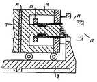
Translated fromKorean제1도는 본 발명의 1실시예인 자기디스크장치 리니어형 액세스기구의 종단면도.1 is a longitudinal sectional view of a magnetic disk device linear access mechanism according to one embodiment of the present invention;
제2도는 제1도의 반동반력 발생장치의 확대도.2 is an enlarged view of the reaction reaction generating device of FIG.
제3도는 제1의 반동 캐리지 안내기구의 종단면도.3 is a longitudinal sectional view of the first reaction carriage guide mechanism.
제4도는 본 발명의 1실시예인 액세스 기구의 종단면도.4 is a longitudinal sectional view of an access mechanism as an embodiment of the present invention.
제5도는 제4도의 반동반력 발생장치의 종단면도.5 is a longitudinal sectional view of the reaction reaction force generating device of FIG.
제6도는 본 발명의 1실시예인 반동반력 발생장치의 종단면도.6 is a longitudinal sectional view of a reaction reaction force generating device according to an embodiment of the present invention.
제7도는 본 발명의 1실시예인 반동반력 발생장치의 종단면도.7 is a longitudinal sectional view of a reaction reaction force generating device according to an embodiment of the present invention.
제8도는 제7도의 I-I선의 단면도.8 is a cross-sectional view taken along the line I-I of FIG.
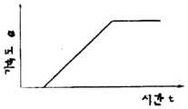
제9도는 액세스기구의 구동가속도의 시간변화를 도시한 도면.9 shows the time change of the driving acceleration of the access mechanism.
제10도는 구동반력에 의한 구동부의 가속도의 미분값의 시간변화를 도시한 도면.10 is a diagram showing a time change of the derivative value of the acceleration of the driving unit by the driving reaction force.
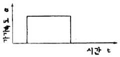
제11도는 반동반력 발생장치가 발생하는 힘의 시간변화를 도시한 도면.11 is a view showing a time change of the force generated by the reaction reaction force generating device.
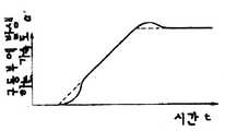
제12도는 반동반력 발생장치가 작동한 경우의 구동부의 가속도의 시간변화를 도시한 도면.12 is a diagram showing a time change of acceleration of a driving unit when the reaction reaction force generating device is operated.
제13도는 본 발명의 1실시예인 자기디스크장치 리니어형 액세스기구의 종단면도.Fig. 13 is a longitudinal sectional view of the magnetic disk device linear access mechanism according to one embodiment of the present invention.
제14도는 진동방지의 원리 모형도.14 is a principle model of vibration prevention.
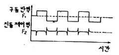
제15도는 구동반력 F1과 진동제어력 F2의 시간변화를 도시한 도면.FIG. 15 is a diagram showing time variation of the driving reaction force F1 and the vibration control force F2 .
제16도는 가가속도의 시간변화를 도시한 도면.FIG. 16 is a diagram showing a time change of acceleration.
제17도는 진동제어력을 가했을때의 자석의 가속도의 계산결과를 도시한 도면.FIG. 17 shows calculation results of acceleration of a magnet when a vibration control force is applied. FIG.
제18도는 제17도의 가속도파형의 주파수 분석결과를 도시한 도면.18 is a diagram showing a frequency analysis result of the acceleration waveform of FIG. 17. FIG.
제19도는 진동방지를 위한 제어계의 1예를 도시한 도면.19 is a view showing an example of a control system for vibration prevention.
제20도는 진동방지를 위한 제어계의 다른 1예를 도시한 도면.20 is a view showing another example of a control system for vibration prevention.
제21도는 진동방지를 위한 제어계의 또 다른 1예를 도시한 도면.21 is a view showing another example of a control system for vibration prevention.
제22도는 적층전기 왜곡소자와 웨이트부재가 1쌍인 반력경감장치의 종단면도.Fig. 22 is a longitudinal sectional view of a reaction force reducing device having a pair of laminated electric distortion elements and a weight member.
제23도는 본 발명의 반력경감장치의 종단면도.23 is a longitudinal sectional view of the reaction force reducing device of the present invention.
제24도는 본 발명의 1실시예인 반력경감장치의 구동방법을 도시한 도면.24 is a view showing a driving method of a reaction force reducing device according to an embodiment of the present invention.
제25도는 본 발명의 1실시예의 종단면도.25 is a longitudinal sectional view of one embodiment of the present invention.
제26도는 제25도의 I-I선의 단면도.26 is a cross-sectional view taken along the line I-I of FIG. 25;
제27도는 본 발명의 1실시예인 로터리형 반력경감장치의 평면도.27 is a plan view of a rotary reaction force reducing device according to an embodiment of the present invention.
* 도면의 주요부분에 대한 부호의 설명* Explanation of symbols for main parts of the drawings
1 : 스핀들 2 : 헤드1: spindle 2: head
3 : 디스크 회전모터 4 : 캐리지3: disc rotation motor 4: carriage
5 : 구동회로 6 : 캐리지 안내로5: driving circuit 6: carriage guide
7 : 보이스 코일모터 8 : 베이스7: voice coil motor 8: base
9 : 커버 10 : 자기 차폐부재9
11 : 반동캐리지 12, 15 : 반동 웨이트11:
13 : 반동반력발생장치 구동회로 14 : 반동 보이스 코일 모터13: Reaction reaction force generator drive circuit 14: Reaction voice coil motor
16 : 안내차 17, 21 : 보이스 코일 모터 코어16:
18 : 레이디얼 하중 부여장치 19 : 반동캐리지가이드18: Radial load applying device 19: Recoil carriage guide
20 : 반동반력 캐리지 22 : 스피링부재20: reaction reaction carriage 22: spring member
본 발명은 자가디스크장치 위치결정기구의 리니어형 액세스기구에 관한 것으로, 특히 고정밀도의 안내정밀도를 필요로 하는 리니어형 액세스 기구에 관한 것이다.BACKGROUND OF THE INVENTION 1. Field of the Invention [0001] The present invention relates to a linear access mechanism of a self-disc device positioning mechanism, and more particularly to a linear access mechanism requiring high precision guide accuracy.
종래의 장치는 리니어형 액세스기구에 발생하는 구동력의 반력을 장치 전체의 강성으로 흡수하던가, 또는 종래의 총포에서 볼 수 있는 반동흡수기구와 같이, 예를들면 일본국 실용신안 공개공보 소화49-49799호에서 볼 수 있는 바와같은 마찰에 의한 덤핑효과를 이용하는 것, 또는 일본국 특허 공개공보 소화58-132470호에서 볼 수 있는 바와같은 반력 피스턴을 타격 피스턴과 180도의 위상차로 동기진동시켜서 반동을 흡수하는 것, 또 일본국 실용신안공보 소화49-9680호에서 볼 수 있는 바와같은 고압가스의 분사에 의해서 얻어지는 반력을 이용하는 것이 있고, 이들을 응용한 반동흡수기구를 사용하고 있었다.The conventional apparatus absorbs the reaction force of the driving force generated in the linear access mechanism with the rigidity of the entire apparatus, or the reaction mechanism such as the recoil absorbing mechanism found in a conventional gun, for example, Japanese Utility Model Publication No. 49-49799 By using frictional dumping effects as seen in the arc, or by absorbing the reaction force by synchronously oscillating the reaction force piston as shown in Japanese Patent Laid-Open No. 58-132470 with a phase difference of 180 degrees. The reaction force obtained by the injection of high pressure gas, as shown in Japanese Utility Model Publication No. 49-9680, was used, and a reaction absorption mechanism using these was used.
상기 종래기술은 자기디스크장치의 액세스기구는 시크동작에서 평균 20∼30Hz, 플로잉 동작에서는 그 10배이상의 주파수로 구동되므로 충분한 광범위의 주파수에 대해서 추종할 수 없고, 또 마찰면의 마모가 발생하여 신뢰성에 문제가 있었다. 또, 광범위한 구동주파수에 대해서 추종할 수 없는 것, 온도의 영향을 받기 쉬운 것 등의 결점이 있었다.In the above-described conventional technique, since the access mechanism of the magnetic disk apparatus is driven at an average frequency of 20 to 30 Hz in seek operation and 10 times or more in the flow operation, it cannot follow a sufficiently wide range of frequencies and wear of friction surfaces occurs. There was a problem with reliability. In addition, there are disadvantages such as being unable to follow a wide range of driving frequencies and being susceptible to temperature.
본 발명의 목적은 액세스기구로의 가진력을 감소하고, 자기디스크장치 전체의 진동을 저감하여 위치결정 정밀도가 높은 리니어형 액세스기구를 제공하는데 있다. 본 발명의 다른 목적은 장치 전체의 진동을 저감할 수 있는 자기디스크장치를 제공하는데 있다.An object of the present invention is to provide a linear access mechanism with high positioning accuracy by reducing the excitation force to the access mechanism and reducing the vibration of the entire magnetic disk apparatus. Another object of the present invention is to provide a magnetic disk apparatus capable of reducing vibration of the entire apparatus.
본 발명의 리니어 액서스기구는 직선적으로 이동가능하게 안내되는 캐리지, 상기 캐리지를 안내하는 안내기구, 상기 캐리지를 직선적으로 왕복운동시키는 보이스 코일모터 및 상기 안내기구와 상기 보이스코일 모터를 지지하는 베이스로 되는 리니어 액세스기구에 있어서, 상기 캐리지를 구동할 때에 발생하는 구동력의 반력을 제거하는 반동반력을 발생하는 반동반력 발생수단을 구비하고, 상기 반동반력이 작용하는 점은 상기 구동력이 작용하는 방향의 연장선상에 있는 것을 특징으로 하고 있다.The linear access mechanism of the present invention includes a carriage guided linearly, a guide mechanism for guiding the carriage, a voice coil motor for linearly reciprocating the carriage, and a base for supporting the guide mechanism and the voice coil motor. A linear access mechanism, comprising: reaction reaction force generating means for generating reaction reaction force for removing reaction force of driving force generated when driving the carriage, wherein the reaction reaction force acts on an extension line in the direction in which the driving force acts. It is characterized by being in.
본 발명의 자기디스크장치는 액세스기구의 구동력에 의한 반력을 역위상의 힘을 부여해서 경감하는 반력 경감장치를 마련한 자기디스크장치에 있어서, 상기 반력경감장치는 적어도 1쌍 이상의 전기왜곡소자와 상기 전기왜곡소자 사이에 마련되고, 이동가능하게 지지된 웨이트부재와 상기 전기왜곡소자를 구동하는 구동장치를 구비하고 있다.In the magnetic disk apparatus of the present invention, a magnetic disk apparatus comprising a reaction force reduction device for reducing the reaction force caused by the driving force of the access mechanism by applying a reverse phase force, wherein the reaction force reduction device includes at least one pair of electric distortion elements and the electric A weight member provided between the distortion elements and movably supported is provided, and a driving device for driving the electric distortion device.
본 발명에 의하면 구동반력과 대략 크기가 같고, 또한 반대방향의 힘을 구동부에 가하는 것에 의해서 구동부로의 가진력을 없애고, 또 이 구동반력을 제거하는 힘을 발생하는 기구를 보이스코일모터로 구성하는 것에 의해서 넓은 범위의 구동 주파수에 추종해서 구동부의 가진력을 저감할 수 있다.According to the present invention, the voice coil motor has a mechanism that generates substantially the same force as the driving reaction force and removes the excitation force to the driving portion by applying a force in the opposite direction to the driving portion. By virtue of following a wide range of drive frequencies, the excitation force of the drive unit can be reduced.
이하 본 발명의 실시예를 제1도에 의해 설명한다. 자기 디스크장치는 데이터의 리드/라이트를 행하는 헤드(2), 데이터가 기억된 디스크를 지지해서 회전시키는 스핀들(1), 스핀들(1)을 구동하는 모터(3), 헤드(2)를 지지하고, 또한 액세스동작을 행하는 캐리지(4), 캐리지(4)를 액세스동작시키는 보이스코일모터(7), 보이스코일모터(7)을 구동하는 구동회로(5), 상기 각 부재를 지지하는 베이스(8), 베이스(8)과 함께 상기 각부재를 외기로부터 차례하는 커버(9)로 구성되어 있다. 다음에 그 동작을 설명한다.An embodiment of the present invention will be described below with reference to FIG. The magnetic disk apparatus supports a
캐리지(4)는 보이스코일모터(7)에 의해서 구동되어 안내로(6)의 위를 왕복운동한다. 이것에 의해서 디스크에 라이트된 데이터를 리드하거나 디스크에 데이터가 라이트된다. 이 데이터의 리드/라이트를 위해서 캐리지(4)의 선단의 헤드(2)를 디스크상의 어떤점에 위치결정하지 않으면 안된다. 이 위치결정 정밀도는 캐리지(4)를 안내로(6)의 위를 안내하는 정밀도와 헤드(2)가 디스크상에서 검출하는 포지션신호를 사용한 구동회로(5)의 정밀도에 의존하고 있다. 그러나 이 위치결정 정밀도에 나쁜 영향을 주는 것이 캐리지(4)를 구동하기 위해서 발생하는 구동반력이다. 즉, 구동반력에 의해 구동부가 가진되고, 따라서 그 가진력에 의해서 발생한 진동이 베이스(8)에 전달되어 스핀들(1)을 진동시키므로 디스크와 헤드(2) 사이에 상대적인 변위가 발생하고, 그것이 위치결정 오차의 원인으로 되기 때문이다. 그래서 본 발명의 1실시예인 제1도에 도시한 바와 같이 종래의 자기디스크장치의 구성에 또 반동반력 발생장치라는 것을 부가한 것이다. 이 반동반력발생장치는 보이스코일모터(7)에 자기차폐부재(10)을 거쳐서 접합된 반동보이스코일모터(14), 이 반동보이스코일모터(14)에 구동되는 반동 캐리지(11), 반동캐리지(11)의 양단에 접합된 반동웨이트(12)와 (15) 및 반동캐리지(11)을 안내하는 안내차(16)과 반동캐리지(11)을 구동하는 반동반력발생장치 구동회로(13)으로 구성되어 있다.The
다음에 이 반동반력 발생장치의 동작에 대해서 설명한다. 캐리지(4)를 구동하면 보이스코일모터(7)에는 반력이 작용한다. 이 반력은 구동부를 진동시키고, 이 진동이 베이스(8)에 전달되어 각부로 전달되는 것이다. 이 결과 각부의 진동에 의해서 높은 위치결정 정밀도가 요구되는 헤드(2)와 디스크사이에 상대변화를 준다. 이것이 위치결정 정밀도를 저하시키는 원인으로 되고, 또 리드/라이트 에러의 원인으로 되는 것이다. 그래서 이 캐리지(4)를 구동하는 것에 의해 발생하는 반력에 걸맞는 반대방향의 힘을 동시에 구동부에 부여하는 것에 의해서 구동부에 작용하는 힘이 외관상 없어져 구동부의 진동저감과 위치결정 정밀도를 향상시킬 수가 있다. 이 반력에 걸맞는 힘을 발생하는 것이 반동반력 발생장치이다. 예를들면, 캐리지(4)를 구동하기 위해서 흐르게 하는 전류를 검출하고, 추진력을 같게한 반동반력 발생장치에 같은 전류를 흐르게 하는 것으로 목적이 달성할 수 있다.Next, the operation of the reaction reaction generating device will be described. When the
또, 반동반력 발생장치의 반동캐리지(11)의 가동부의 질량을 캐리지(4)의 가동부의 질량보다 크게 하는 것으로 같은 힘이 발생해도 반동캐리지(11)쪽이 스트로크가 작게 되고 장치도 소형으로 할 수 있다.In addition, even if the same force is generated as the mass of the movable part of the
캐리지(4)의 구동전류에는 보이스코일의 역기전력이나 잡음성분이 당연히 포함되어 온다. 이 구동전류에 편승한 고주파수의 혼란성분은 캐리지(4)를 진동시키는 원인으로 되는 것이지만 구동부에 반력으로써 전달되는 경우 전달경로에서의 감쇠효과에 의해서 구동부를 진동시키는 직접적인 원인으로는 되지 않는다고 생각된다. 따라서 캐리지(4)의 구동반력을 구동전류 그 자체에서 피드백하는 것보다 미리 전류파형에서 고주파성분을 제거하여 구동주파수 근방의 성분만 반동반력 발생장치에 부여하는 것에 의해서 보다 유효한 기능을 발휘할 수가 있다.The driving current of the
제1도에 있어서 반동반력 발생장치의 구동회로(13)에 반동반력을 발생시키는 신호를 만들기 위해서 구동회로(13)에 주는 정보로써 캐리지(4)의 구동전류나 구동부에 발생하는 가속도를 사용할 수가 있다.In FIG. 1, the driving current of the
또, 제1도에 도시되어 있는 바와같이 구동부의 반력을 조화시킴과 동시에 구동부와 반동반력 발생장치를 베이스(8)에 대해서 이동가능하게 하는 것에 의해 구동부에 작용하는 힘을 베이스(8)에 직접 전달하는 일없이 캐리지(4)의 구동을 할 수 있다. 이것에 의해서 장치 전체의 진동을 저감하여 위치결정 정밀도를 향상시킬 수 있다.In addition, as shown in FIG. 1, the force acting on the drive unit is directly applied to the
제2도는 제1도의 실시예인 반동반력 발생장치의 상세한 도면이다. 제3도는 제2도의 반동캐리지(11)의 안내장치의 확대도이다.FIG. 2 is a detailed view of the reaction reaction generating device which is the embodiment of FIG. FIG. 3 is an enlarged view of the guide device of the
제4도는 본 발명의 1실시예를 도시한다. 이 실시예는 보이스코일모터(7)에 자기차폐부재(10)을 거쳐서 접합된 적층 전기왜곡소자(21), 이 적층 전기왜곡소자(21)에 보이스 코일모터(7)과는 반대쪽에 접합된 반동웨이트(19) 및 적층전기왜곡소자(21)에 인가하는 전압을 제어하는 반동반력 발생장치의 구동회로(13)으로 구성된다. 이 실시예의 특징은 높은 주파수에 응답할 수 있는 것, 대출력(큰힘)을 발생할 수 있는 것, 구동을 위한 기구가 없으므로 마모의 염려가 없는 것, 구동부가 적층전기왜곡소자로 형성되어 있으므로 소형화가 가능한 것등을 들 수 있다.4 shows one embodiment of the present invention. In this embodiment, the laminated
제5도는 제4도의 반동반력 발생장치의 확대도이다. 제6도는 적층 전기왜곡소자(23)을 동심원형상으로 적층하여 그 내부둘레면 또는 외부둘레면을 구동에 이용하는 것을 목적으로 한 것이다. 제7도는 제6도를 더욱 상세하게 한 것이다. 이 동작원리는 적층된 전기왜곡소자(26)에 반경방향의 왜곡을 주고, 그리고 인접한 전기왜곡소자에 위상차가 있는 인가전압을 가하는 것에 의해 적층된 전기왜곡소자(26)의 반경방향의 왜곡에 진행파를 형성한다. 이 실시예에서는 적층된 전기왜곡소자(26)의 외부둘레가 축방향에 고정되어 있으므로 내부둘레면에서 진행파가 발생한다. 이 때문에 반동웨이트(22)와 적층 전기왜곡소자(26)은 모터가이드(27)위를 축방향으로 운동한다. 전기왜곡소자를 적층하고, 그 적층한 방향의 왜곡을 이용하는 경우 큰 왜곡을 얻기 위해서는 그 적층의 양을 대단히 크게 할 필요가 있다. 그러나 이 제7도에 도시한 실시예에서는 큰 스트로크를 얻는 것은 용이하다. 제8도는 제7도의 반동반력발생장치의 단면도이다.5 is an enlarged view of the reaction reaction force generating device of FIG. FIG. 6 is for the purpose of laminating the laminated electro-
제9도, 제10도, 제11도, 제12도는 구동방법에 관한 일련의 관계를 도시한 것이다. 제9도는 캐리지(3)의 구동에 의해서 구동부에 발생하는 반력에 의한 가속도의 시간변화를 도시한 것이다. 제10도는 제2도에 도시한 가속도의 미분값의 시간변화를 도시한 것이다. 제11도는 반동반력 발생장치가 발생하는 힘의 시간변화이다. 제12도는 반력이 작용하고 있는 구동부에 반동반력 발생장치가 발생하는 힘을 가했을때의 구동부에 발생하는 가속도의 시간변화를 도시한 것이다. 이 일련의 도면에 도시한 바와같이 구동부에 발생하는 가속도의 급변을 완화하는 것에 의해 구동부에 충격적인 힘이 작용하는 것을 피할 수가 있다. 이것에 의해 액세스 기구계의 진동을 감소하고, 또 자기 디스크장치 전체의 진동을 감소할 수 있게 된다. 따라서 액세스 기구의 위치결정 정밀도를 높이는 것을 기대할 수 있다. 다음에 반동반력 발생장치에 발생시키는 힘의 파형을 구하는 방법에 대해서 기술한다.9, 10, 11, and 12 show a series of relations relating to the driving method. 9 shows the time change of the acceleration due to the reaction force generated in the drive unit by the drive of the
구동반력에 의한 가속도를 제9도와 같이 1차 함수로 나타낸다.Acceleration due to driving reaction is expressed as a linear function as shown in FIG.

여기서 α는 가속도, K1은 비례정수, t는 시간이다. 반동반력 발생장치가 발생하는 가속도 α'가 3차식으로 근사되는 것으로 한다.Where α is the acceleration, K1 is the proportional constant, and t is the time. It is assumed that the acceleration α 'generated by the reaction reaction force generating device is approximated by a cubic equation.

이 2개의 가속도가 원활하게 접속하기 위해서는In order to connect these two accelerations smoothly

로 된다. 따라서 (1)식과 (2)식에 상기 조건을 대입하면It becomes Therefore, substituting the above conditions into equations (1) and (2)


와 같이 a, b, c, d를 결정할 수 있다. 이 결과에서 가속도의 미분값에 비례한 반동반력의 가속도를 구동부에 가하는 것으로 본 발명의 목적을 달성할 수가 있다.As can be determined a, b, c, d. As a result, the object of the present invention can be achieved by applying the acceleration of the reaction reaction force proportional to the derivative value of the acceleration to the drive unit.
다음에 본 발명의 다른 실시예를 제13도에 의해 설명한다. 자기디스크장치는 데이터의 리드/라이트를 행하는 헤드(2), 데이터가 기억된 디스크(23)을 지지해서 회전시키는 스핀들(1), 스핀들(1)을 구동하는 모터(3), 헤드(2)를 지지하고, 또한 액세스 동작을 행하는 캐리지(4), 캐리지(4)를 액세스동작시키는 보이스 코일모터(7)을 구동하는 제어회로(5), 상기 각 부재를 지지하는 베이스(8) 및 베이스(8)과 함께 상기 각 부재를 외기로부터 차폐하는 커버(9)로 구성된다. 다음에 그 동작을 설명한다.Next, another embodiment of the present invention will be described with reference to FIG. The magnetic disk apparatus includes a
캐리지(4)는 보이스코일모터(7)에 의해 구동되어 안내로(6)의 위를 왕복운동한다. 이것에 의해서 디스크에 라이트된 데이터를 리드하거나 디스크에 데이터가 라이트된다. 이 데이터의 리드/라이트를 위해서 캐리지(4)의 선단의 헤드(2)를 디스크(23)상의 어떤점에 위치결정하지 않으면 안된다. 이 위치결정 정밀도는 캐리지(4)를 안내로(6)의 위를 안내하는 정밀도와 헤드(2)로 디스크상에서 검출하는 포지션 신호를 사용한 제어회로(5)의 정밀도에 의존하고 있다.The
그러나 이 위치결정 정밀도에 나쁜 영향을 주는 것이 캐리지(4)를 구동하기 위해 발생하는 구동반력이다. 즉, 이 구동반력에 의해 구동부가 가진되고, 그 진동이 전달되어서 스핀들(1)을 진동시킨다. 이 결과 디스크(23)과 헤드(2)사이에 상대적인 변위가 발생하여 그것이 위치결정오차의 원인으로 되기 때문이다. 그래서 본 발명의 실시예인 제13도에 도시한 바와같이 종래의 자기 디스크장치의 구성에 또 반력경감장치를 부가한 것이다. 이 반력경감장치는 보이스코일모터(7)에 웨이트부재(25)를 적층된 전기왜곡소자(24)사이에 끼워넣어 부착하고, 적층왜곡소자(24)를 발생하는 구동반력에 따라서 구동하는 전기왜곡소자구동회로(27)을 부가해서 구성된다. 적층전기왜곡소자(24)는 웨이트부재(25)를 끼워서 양쪽에 같은 수로 적어도 1개이상의 동일간격으로 마련되어 있다. 또 적층전기왜곡소자(24)는 각각의 한쪽이 보이스코일모터(7)에 고정되어 있다. 웨이트부재(25)는 적층 전기왜곡소자(24)와 함께 왕복운동한다. 또 웨이트부재(25)의 기속도의 운동방법과 적층 전기왜곡소자(24)의 변위의 방향은 같다. 웨이트부재(25)의 운동에 의해서 힘을 얻는 것이므로 구동반력을 경감시키는 경우에는 웨이트부재(25)의 가속도운동방향과 구동반력의 방향은 일치한다.However, it is the driving reaction generated to drive the
여기서 진동방지의 원리에 대해서 설명한다. 제14도는 진동방지의 원리모델을 도시한 것으로써, 질량 m1의 보이스코일모터자석(30)은 스프링요소(34)와 덤핑요소(33)으로 지지되고, 이 보이스코일모터자석(30)에 적층전기왜곡소자(32), 웨이트부재(31)이 차례로 접속되어 있다. 보이스코일모터자석(30)에 구동반력 F1이 작용하면 변위한다. 그리고 구동반력 F1이 진동적이면 진동한다. 이 진동을 감소하기 위해서 구동반력 F1을 감소시키면 된다. 그러나 구동반력 F1이 DC성분뿐이면 진동은 발생하지 않는다. 따라서 구동반력 F1의 변동분만큼 제거시키면 되게 된다.Here, the principle of vibration prevention will be described. FIG. 14 shows a principle model of vibration suppression, in which the voice
즉, 구동반력 F1의 미분값, 즉 보이스코일모터자석(30)에서 보면 보이스코일모터자석(30)의 가가속도에 따른 피드백을 행하게 하면 된다. 진동방지를 위한 힘을 F2로 해서 상술한 것을 운동방정식으로 나타내면That is, the differential value of the driving reaction force F1 , ie, the voice


로 된다.It becomes
제15도는 구동반력 F1과 진동제어력 F2의 시간변화의 1예이다. 진동방지에 필요한 힘은 구동반력 F1이 급변하는 부분이므로 F2는 도면에 도시한 바와같은 파형으로 된다. 제16도는 가가속도의 시간변화의 1예이다.FIG. 15 is an example of time change of the driving reaction force F1 and the vibration control force F2 . Since the force required for vibration prevention is a portion where the driving reaction force F1 changes rapidly, F2 becomes a waveform as shown in the figure. 16 is an example of the time change of the acceleration.
다음에 제15도에 도시한 바와같은 진동방지를 위한 힘을 발생시키는 방법에 대하여 설명한다. 제14도에 도시한 웨이트부재(31)(질량 m2)을 가속도운동시키면 관성력 Fc=m2X2가 발생한다. 이 웨이트부재(31)을 가속도 운동시키기 위한 반력이 제15도의 진동제어력 F2로써 이용된다. 웨이트부재(31)을 움직이기 위해서는 적층전기왜곡소자(32)를 가속도적으로 변형시키면 된다. 예를들면 적층전기왜곡소자(32)에 압전소자를 사용하면 높은 주파수 응답성이 있으므로 높은 주파수의 가진력성분에 대해서 진동제어력을 발생할 수 있다. 그리고 웨이트부재(31)을 가속도 운동시켜서 얻어지는 관성력중 보이스코일모터자석(30)에 진동제어력으로써 이용할 수 있는 힘을 다음식으로 나타낼 수가 있다.Next, a method of generating a force for preventing vibration as shown in FIG. 15 will be described. When the weight member 31 (mass m2 ) shown in FIG. 14 is subjected to acceleration movement, the inertia force Fc = m2 X2 is generated. The reaction force for accelerating the

제17도는 식(7), (8), (9)를 사용해서 자석의 가속도의 시간변화를 계산해 본 것이다. 피드백량(진동제어력의 크기)을 증대하면 자석의 가속도의 최대값으로 된다.In FIG. 17, the time change of the acceleration of the magnet is calculated using equations (7), (8), and (9). Increasing the feedback amount (the magnitude of the vibration control force) results in the maximum value of the acceleration of the magnet.
제18도는 진동제어력이 가해진 경우와 가해지지 않은 경우의 자석의 가속도 파형의 주파수성분의 차이를 도시한 것이다. 진동제어력을 가한 경우는 주파수성분이 감소한다.FIG. 18 shows the difference between the frequency components of the acceleration waveform of the magnet when the vibration control force is applied and when it is not applied. When the vibration control force is applied, the frequency component decreases.
이상 반력경감장치의 구동방법에 대해서 설명하였다. 다음에 반력경감장치의 로구성에 대해서 설명한다.The driving method of the reaction force reducing device has been described above. Next, the furnace configuration of the reaction force reducing device will be described.
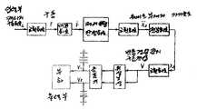
제19도는 반력경감장치의 구동방법을 실현하기 위한 제어계의 1예이다. 캐리지 구농전류를 입력으로 하고, 그 미분값에서 보이스코일모터자석의 가가속도에 근사적으로 대응하고 있는 구동반력의 미분값을 구해서 제어에 이용하고 있다. 전류의 검출은 용이하므로 가속도계등의 센서종류가 불필요한 점에서 유리하다.19 is an example of a control system for realizing the driving method of the reaction force reducing device. The carriage residual current is used as an input, and the derivative value of the driving reaction force corresponding to the acceleration of the voice coil motor magnet is calculated from the derivative value and used for control. Since the current can be easily detected, it is advantageous in that a sensor type such as an accelerometer is unnecessary.
제20도는 반력경감장치의 구동방법을 실현하기 위한 제어계의 1예이다. 보이스코일모터자석의 가속도를 입력으로 하고, 그 미분값, 즉 자석의 가가속도를 제어에 사용하고 있다. 이 방법에서는 가속도센서가 필요하지만 제19도에 도시한 전류에서 구동력으로 변환하는 회로가 불필요하여 회로구성수가 감소한다.20 is an example of a control system for realizing the driving method of the reaction force reducing device. The acceleration of the voice coil motor magnet is used as an input, and its derivative value, that is, the acceleration of the magnet is used for control. In this method, an acceleration sensor is required, but a circuit for converting the current into the driving force shown in FIG. 19 is unnecessary, thereby reducing the number of circuit configurations.
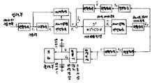
제21도는 반력경감장치의 구동방법을 실현하기 위한 제어계의 1예이다. 이 예에서는 캐리지 구동전류를 하고, 또한 제어대상의 진동을 모의(제어대상의 고유진동수를 고려하고 있다)한 피드백회로가 조 센서를 않는 안정된 제어회로를 구성하고 있다.21 is an example of a control system for realizing the driving method of the reaction force reducing device. In this example, a feedback circuit that performs a carriage drive current and simulates the vibration of the control target (considering the natural frequency of the control target) constitutes a stable control circuit without a jaw sensor.
제22도는 적층전기왜곡소자(24)를 웨이트부재(25)의 한쪽에만 마련한 경우이다. 이 경우 웨이트부재(25)의 운동이 불안정하게 되고, 또 웨이트부재(25)가 제22도의 좌측으로 이동할 때 전기왜곡소자(24)에는 인장력이 작용한다. 일반적으로 적층된 전기왜곡소자(24)에 인장력을 가하는 것은 바람직하지 않다. 따라서 본 발명의 1실시예로써 도시한 제13도의 예의 구조가 바람직하다. 제23도는 제13도의 반력경감장치를 확대한 것이다. 이 구조이면 웨이트부재(25)의 양쪽의 적층전기왜곡소자(24)가 동시에 역위상의 운동을 하면 인장력을 작용하는 일은 없다. 이것을 더욱 확실하게 행하기 위해서는 양쪽의 적층전기왜곡소자(24)의 운동 개시시각을 조금 어긋나게 하면 된다.22 shows a case in which the laminated electro-
제24도는 이 상기한 예를 도시한 것이다. 예를들면 제23도에서 웨이트부재(25)를 도면의 우측으로 움직이게 하고자 하는 경우 좌측의 전기왜곡소자(24)의 운동개시시각은 우측의 전기왜곡소자의 운동개시시각보다 약간 빠르게 하면 된다.Fig. 24 shows this above example. For example, in FIG. 23, when the
제25도는 본 발명의 다른 1실시예이다. 본 발명의 특징은 웨이트부재(25)에 대해서 양쪽의 적층전기왜곡소자(24)를 서로 틀리게 마련하고, 각 전기왜곡소자(24)의 힘의 작용점이 각각 동일직선상으로 되도록 배치한 것이다. 이 방법을 사용하면 웨이트부재(25)의 두께분만큼 양쪽의 적층전기왜곡소자(24)의 거리를 축소시킬 수가 있다. 따라서 반력경감장치의 크기를 소형화할 수 있다. 제26도는 제25도의 I-I선의 단면을 도시한 것이다.25 is another embodiment of the present invention. The feature of the present invention is that the stacked
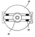
제27도는 로터리형 액세스기구에 적용할 수 있는 1실시예이다. 이 예에서는 웨이트부재(25)가 적층 전기왜곡소자(24)의 신축에 의해서 회전운동하고 모멘트에 의한 반력을 경감할 수 있다.27 shows one embodiment applicable to a rotary access mechanism. In this example, the
이상은 적층 전기왜곡소자(24)를 사용한 경우로써, 예를들면 이 적층전기왜곡소자(24)대신에 형상기억합금을 사용할 수도 있다. 단, 이 경우에는 압축력보다 인장력에 강하므로 상술한 적층전기왜곡소자(24)의 경우와 달라서 인장쪽을 선행시키면 좋다. 형상기억합금을 사용하는 경우 더욱 경량화, 소형화가 가능하게 된다.The above is a case where the
본 발명에 의하면 리니어형 액세스기구의 캐리지를 구동하기 위해서 발생하는 구동반력을 경감하고, 또한 장치 전체의 진동을 저감할 수 있다. 그 결과 리니어형 액세스 기구의 위치결정 정밀도를 향상시키는 효과가 있다. 또한 소형이고 신뢰성이 높은 구동반력의 경감장치로 할 수 있는 효과가 있다.According to the present invention, drive reaction force generated in order to drive the carriage of the linear access mechanism can be reduced, and vibration of the entire apparatus can be reduced. As a result, there is an effect of improving the positioning accuracy of the linear access mechanism. In addition, there is an effect that can be made as a compact and reliable drive reaction reducing device.
Claims (10)
Translated fromKoreanApplications Claiming Priority (4)
| Application Number | Priority Date | Filing Date | Title |
|---|---|---|---|
| JP63063376AJP2559453B2 (en) | 1988-03-18 | 1988-03-18 | Linear access mechanism |
| JP63-63376 | 1988-03-18 | ||
| JP63166745AJP2585729B2 (en) | 1988-07-06 | 1988-07-06 | Access mechanism for magnetic disk device |
| JP63-166745 | 1988-07-06 |
Publications (2)
| Publication Number | Publication Date |
|---|---|
| KR890015250A KR890015250A (en) | 1989-10-28 |
| KR910007482B1true KR910007482B1 (en) | 1991-09-26 |
Family
ID=26404496
Family Applications (1)
| Application Number | Title | Priority Date | Filing Date |
|---|---|---|---|
| KR1019890003012AExpiredKR910007482B1 (en) | 1988-03-18 | 1989-03-11 | Linear access mechanism and magnetic disk device |
Country Status (5)
| Country | Link |
|---|---|
| US (1) | US5062012A (en) |
| EP (1) | EP0333128B1 (en) |
| KR (1) | KR910007482B1 (en) |
| CN (1) | CN1013157B (en) |
| DE (1) | DE68916286T2 (en) |
Families Citing this family (36)
| Publication number | Priority date | Publication date | Assignee | Title |
|---|---|---|---|---|
| US5208497A (en)* | 1989-04-17 | 1993-05-04 | Sharp Kabushiki Kaisha | Linear driving apparatus |
| US5313446A (en)* | 1990-03-30 | 1994-05-17 | Canon Kabushiki Kaisha | Disc drive device having a head carriage |
| US5153494A (en)* | 1990-04-06 | 1992-10-06 | International Business Machines Corp. | Ultrafast electro-dynamic x, y and theta positioning stage |
| JP2752248B2 (en)* | 1990-11-30 | 1998-05-18 | シャープ株式会社 | Linear motor device |
| US5239340A (en)* | 1990-11-30 | 1993-08-24 | Sharp Kabushiki Kaisha | Linear motor device having vibration reduction unit |
| US5459383A (en)* | 1991-02-07 | 1995-10-17 | Quantum Corporation | Robust active damping control system |
| US5510939A (en)* | 1992-07-16 | 1996-04-23 | Micropolis Corporation | Disk drive with adaptive positioning |
| US5297024A (en)* | 1992-12-01 | 1994-03-22 | Sgs-Thomson Microelectronics, Inc. | Voice coil driver with variable gain in seek and track-follow modes |
| JPH0982048A (en)* | 1995-09-12 | 1997-03-28 | Toshiba Corp | Head actuator mechanism applied to a disk recording / reproducing apparatus and its drive control method |
| DE19810996A1 (en)* | 1998-03-13 | 1999-09-16 | Krauss Maffei Ag | Motor to drive useful load in machine |
| US6198580B1 (en) | 1998-08-17 | 2001-03-06 | Newport Corporation | Gimballed optical mount |
| US6516130B1 (en) | 1998-12-30 | 2003-02-04 | Newport Corporation | Clip that aligns a fiber optic cable with a laser diode within a fiber optic module |
| FR2790115B1 (en)* | 1999-02-23 | 2001-05-04 | Micro Controle | METHOD AND DEVICE FOR MOVING A MOBILE ON AN ELASTICALLY MOUNTED BASE |
| US6583964B1 (en)* | 1999-03-18 | 2003-06-24 | Hitachi Global Storage Technologies Netherlands B.V. | Disk drive with mode canceling actuator |
| US6511035B1 (en) | 1999-08-03 | 2003-01-28 | Newport Corporation | Active vibration isolation systems with nonlinear compensation to account for actuator saturation |
| US6633457B1 (en) | 2000-07-25 | 2003-10-14 | Data Storage Institute | Actuator assembly with orthogonal force generation |
| US6655840B2 (en) | 2001-02-13 | 2003-12-02 | Newport Corporation | Stiff cross roller bearing configuration |
| US6601524B2 (en) | 2001-03-28 | 2003-08-05 | Newport Corporation | Translation table with a spring biased dovetail bearing |
| US6765743B2 (en) | 2001-04-18 | 2004-07-20 | Hitachi Global Storage Technologies Netherlands. B.V. | Micro-actuator transducer stack inertia cancellation control |
| US6791058B2 (en) | 2001-04-25 | 2004-09-14 | Newport Corporation | Automatic laser weld machine for assembling photonic components |
| US6568666B2 (en) | 2001-06-13 | 2003-05-27 | Newport Corporation | Method for providing high vertical damping to pneumatic isolators during large amplitude disturbances of isolated payload |
| US6619611B2 (en) | 2001-07-02 | 2003-09-16 | Newport Corporation | Pneumatic vibration isolator utilizing an elastomeric element for isolation and attenuation of horizontal vibration |
| US6621241B2 (en)* | 2001-12-20 | 2003-09-16 | Dac International, Inc. | System and method for reducing oscillating tool-induced reaction forces |
| US6966535B2 (en) | 2002-05-07 | 2005-11-22 | Newport Corporation | Snubber for pneumatically isolated platforms |
| US7320455B2 (en) | 2003-10-24 | 2008-01-22 | Newport Corporation | Instrumented platform for vibration-sensitive equipment |
| US8231098B2 (en) | 2004-12-07 | 2012-07-31 | Newport Corporation | Methods and devices for active vibration damping of an optical structure |
| US7989084B2 (en)* | 2007-05-09 | 2011-08-02 | Motor Excellence, Llc | Powdered metal manufacturing method and devices |
| DE102008038728A1 (en) | 2008-08-12 | 2010-02-18 | J.G. WEISSER SöHNE GMBH & CO. KG | Production machine for non-circular workpieces |
| JP2012507983A (en) | 2008-11-03 | 2012-03-29 | モーター エクセレンス, エルエルシー | Multiphase transverse and / or commutated flux system |
| WO2011115634A1 (en)* | 2010-03-15 | 2011-09-22 | Motor Excellence Llc | Transverse and/or commutated flux systems having phase offset |
| EP2548288A1 (en)* | 2010-03-15 | 2013-01-23 | Motor Excellence, LLC | Transverse and/or commutated flux systems configured to provide reduced flux leakage, hysteresis loss reduction, and phase matching |
| US8395291B2 (en)* | 2010-03-15 | 2013-03-12 | Electric Torque Machines, Inc. | Transverse and/or commutated flux systems for electric bicycles |
| US8854171B2 (en) | 2010-11-17 | 2014-10-07 | Electric Torque Machines Inc. | Transverse and/or commutated flux system coil concepts |
| US8405275B2 (en) | 2010-11-17 | 2013-03-26 | Electric Torque Machines, Inc. | Transverse and/or commutated flux systems having segmented stator laminations |
| US8952590B2 (en) | 2010-11-17 | 2015-02-10 | Electric Torque Machines Inc | Transverse and/or commutated flux systems having laminated and powdered metal portions |
| JP6014047B2 (en) | 2010-12-29 | 2016-10-25 | ニューポート・コーポレイションNewport Corporation | Tunable vibration damper and manufacturing and tuning method |
Family Cites Families (12)
| Publication number | Priority date | Publication date | Assignee | Title |
|---|---|---|---|---|
| US3742159A (en)* | 1972-04-13 | 1973-06-26 | Mallory & Co Inc P R | Multi-cam timer with clutch means allowing independent cam adjustment and rotation of cam assembly independent of motor |
| US3825039A (en)* | 1972-06-05 | 1974-07-23 | Domain Ind Inc | Twist-tie bag closing machine |
| JPS5611657A (en)* | 1979-07-10 | 1981-02-05 | Mitsubishi Electric Corp | Magnetic head support mechanism |
| US4612592A (en)* | 1979-12-26 | 1986-09-16 | Burroughs Corporation | Dual coil/dual magnet actuator |
| JPS58132470A (en)* | 1982-02-02 | 1983-08-06 | 日本国有鉄道 | Recoilless hydraulic hammer |
| JPS58133672A (en)* | 1982-02-04 | 1983-08-09 | Olympus Optical Co Ltd | Tracking controller |
| US4516231A (en)* | 1982-08-26 | 1985-05-07 | Rca Corporation | Optical disc system having momentum compensation |
| JPS5965640A (en)* | 1982-10-07 | 1984-04-13 | Toyota Motor Corp | vibration absorber |
| GB2129186A (en)* | 1982-10-29 | 1984-05-10 | Atasi Corp | Disk drive actuator structure |
| US4616277A (en)* | 1984-06-15 | 1986-10-07 | Memorex Corporation | Disk drive storage system having means for compensating for seek driving forces coupled between head actuators |
| JPS61203861A (en)* | 1985-01-07 | 1986-09-09 | プライアム コ−ポレ−シヨン | Compact voice coil motor and disc driver using the same |
| JPS63206148A (en)* | 1987-02-19 | 1988-08-25 | Olympus Optical Co Ltd | Linear motor for optical head |
- 1989
- 1989-03-11KRKR1019890003012Apatent/KR910007482B1/ennot_activeExpired
- 1989-03-14DEDE68916286Tpatent/DE68916286T2/ennot_activeExpired - Fee Related
- 1989-03-14EPEP89104487Apatent/EP0333128B1/ennot_activeExpired - Lifetime
- 1989-03-16USUS07/324,556patent/US5062012A/ennot_activeExpired - Fee Related
- 1989-03-18CNCN89101549Apatent/CN1013157B/ennot_activeExpired
Also Published As
| Publication number | Publication date |
|---|---|
| US5062012A (en) | 1991-10-29 |
| CN1013157B (en) | 1991-07-10 |
| KR890015250A (en) | 1989-10-28 |
| EP0333128A3 (en) | 1991-11-27 |
| DE68916286T2 (en) | 1994-12-01 |
| CN1036853A (en) | 1989-11-01 |
| EP0333128B1 (en) | 1994-06-22 |
| DE68916286D1 (en) | 1994-07-28 |
| EP0333128A2 (en) | 1989-09-20 |
Similar Documents
| Publication | Publication Date | Title |
|---|---|---|
| KR910007482B1 (en) | Linear access mechanism and magnetic disk device | |
| US6034834A (en) | Head driving device and method for driving the same for reducing error due to actuator structure vibration | |
| US4908816A (en) | Voice coil motor with linearized force constant | |
| CN113205833A (en) | Suspension for magnetic disk device | |
| JPH11332265A (en) | Piezoelectric motor | |
| CA1198814A (en) | Carriage assembly | |
| JPS61271673A (en) | Head access device for magnetic disc device | |
| JPH01238450A (en) | Linear access mechanism | |
| US4263632A (en) | Vibration damper for a transducer carriage drive mechanism for use in a diskette system | |
| JP2585729B2 (en) | Access mechanism for magnetic disk device | |
| JPH02107471A (en) | Driving method of linear moving body, driving device and printer | |
| JP2657309B2 (en) | Access mechanism for rotating disk type recording device | |
| JP3103632B2 (en) | Rotary information recording / reproducing device | |
| JPH0278080A (en) | Cable guide mechanism in linear actuator | |
| US6636385B2 (en) | Magnetic disc apparatus having actuator for head positioning mechanism | |
| JP3539332B2 (en) | Disk unit | |
| JPH01162279A (en) | Control circuit of magnetic disk device | |
| Vermeulen et al. | Development of controlled surface acoustic wave planar actuators | |
| JPH02134793A (en) | magnetic disk device | |
| JPH04248170A (en) | Magnetic head positioning device | |
| JPH01194174A (en) | magnetic disk device | |
| Yoshida et al. | Vibration reduction of a small magnetic disk drive using a nonreacting, twin-drive actuator | |
| JPH05334690A (en) | Movable head | |
| JPH08273314A (en) | Linear reciprocating moving body | |
| JPS63257967A (en) | Magnetic head positioning mechanism |
Legal Events
| Date | Code | Title | Description |
|---|---|---|---|
| A201 | Request for examination | ||
| PA0109 | Patent application | St.27 status event code:A-0-1-A10-A12-nap-PA0109 | |
| PA0201 | Request for examination | St.27 status event code:A-1-2-D10-D11-exm-PA0201 | |
| R17-X000 | Change to representative recorded | St.27 status event code:A-3-3-R10-R17-oth-X000 | |
| PG1501 | Laying open of application | St.27 status event code:A-1-1-Q10-Q12-nap-PG1501 | |
| G160 | Decision to publish patent application | ||
| PG1605 | Publication of application before grant of patent | St.27 status event code:A-2-2-Q10-Q13-nap-PG1605 | |
| E701 | Decision to grant or registration of patent right | ||
| PE0701 | Decision of registration | St.27 status event code:A-1-2-D10-D22-exm-PE0701 | |
| GRNT | Written decision to grant | ||
| PR0701 | Registration of establishment | St.27 status event code:A-2-4-F10-F11-exm-PR0701 | |
| PR1002 | Payment of registration fee | St.27 status event code:A-2-2-U10-U11-oth-PR1002 Fee payment year number:1 | |
| PR1001 | Payment of annual fee | St.27 status event code:A-4-4-U10-U11-oth-PR1001 Fee payment year number:4 | |
| PR1001 | Payment of annual fee | St.27 status event code:A-4-4-U10-U11-oth-PR1001 Fee payment year number:5 | |
| PR1001 | Payment of annual fee | St.27 status event code:A-4-4-U10-U11-oth-PR1001 Fee payment year number:6 | |
| PR1001 | Payment of annual fee | St.27 status event code:A-4-4-U10-U11-oth-PR1001 Fee payment year number:7 | |
| PR1001 | Payment of annual fee | St.27 status event code:A-4-4-U10-U11-oth-PR1001 Fee payment year number:8 | |
| R18-X000 | Changes to party contact information recorded | St.27 status event code:A-5-5-R10-R18-oth-X000 | |
| PN2301 | Change of applicant | St.27 status event code:A-5-5-R10-R13-asn-PN2301 St.27 status event code:A-5-5-R10-R11-asn-PN2301 | |
| PR1001 | Payment of annual fee | St.27 status event code:A-4-4-U10-U11-oth-PR1001 Fee payment year number:11 | |
| FPAY | Annual fee payment | Payment date:20020916 Year of fee payment:12 | |
| PR1001 | Payment of annual fee | St.27 status event code:A-4-4-U10-U11-oth-PR1001 Fee payment year number:12 | |
| LAPS | Lapse due to unpaid annual fee | ||
| PC1903 | Unpaid annual fee | St.27 status event code:A-4-4-U10-U13-oth-PC1903 Not in force date:20030927 Payment event data comment text:Termination Category : DEFAULT_OF_REGISTRATION_FEE | |
| PC1903 | Unpaid annual fee | St.27 status event code:N-4-6-H10-H13-oth-PC1903 Ip right cessation event data comment text:Termination Category : DEFAULT_OF_REGISTRATION_FEE Not in force date:20030927 | |
| R18-X000 | Changes to party contact information recorded | St.27 status event code:A-5-5-R10-R18-oth-X000 | |
| P22-X000 | Classification modified | St.27 status event code:A-4-4-P10-P22-nap-X000 |