KR910006661B1 - Magneto-opticla head - Google Patents
Magneto-opticla headDownload PDFInfo
- Publication number
- KR910006661B1 KR910006661B1KR1019890000347AKR890000347AKR910006661B1KR 910006661 B1KR910006661 B1KR 910006661B1KR 1019890000347 AKR1019890000347 AKR 1019890000347AKR 890000347 AKR890000347 AKR 890000347AKR 910006661 B1KR910006661 B1KR 910006661B1
- Authority
- KR
- South Korea
- Prior art keywords
- medium
- polarization
- laser
- diffraction
- reflection
- Prior art date
- Legal status (The legal status is an assumption and is not a legal conclusion. Google has not performed a legal analysis and makes no representation as to the accuracy of the status listed.)
- Expired
Links
- 230000010287polarizationEffects0.000claimsdescription34
- 230000003287optical effectEffects0.000claimsdescription25
- 239000004065semiconductorSubstances0.000claimsdescription15
- 238000001514detection methodMethods0.000claimsdescription9
- 230000008859changeEffects0.000claimsdescription3
- 230000005291magnetic effectEffects0.000description14
- 238000010586diagramMethods0.000description5
- 230000003993interactionEffects0.000description5
- 230000005415magnetizationEffects0.000description4
- 230000005855radiationEffects0.000description4
- 230000008901benefitEffects0.000description3
- 230000005381magnetic domainEffects0.000description3
- 239000000463materialSubstances0.000description3
- 238000013500data storageMethods0.000description2
- 230000007246mechanismEffects0.000description2
- 238000000034methodMethods0.000description2
- 238000010521absorption reactionMethods0.000description1
- 238000003491arrayMethods0.000description1
- 201000009310astigmatismDiseases0.000description1
- 230000005540biological transmissionEffects0.000description1
- 238000007796conventional methodMethods0.000description1
- 230000000694effectsEffects0.000description1
- 230000005294ferromagnetic effectEffects0.000description1
- 238000004519manufacturing processMethods0.000description1
- 239000011368organic materialSubstances0.000description1
- 239000000049pigmentSubstances0.000description1
- 239000002985plastic filmSubstances0.000description1
- 229920000642polymerPolymers0.000description1
- 230000000007visual effectEffects0.000description1
Images


Classifications
- G—PHYSICS
- G11—INFORMATION STORAGE
- G11B—INFORMATION STORAGE BASED ON RELATIVE MOVEMENT BETWEEN RECORD CARRIER AND TRANSDUCER
- G11B11/00—Recording on or reproducing from the same record carrier wherein for these two operations the methods are covered by different main groups of groups G11B3/00 - G11B7/00 or by different subgroups of group G11B9/00; Record carriers therefor
- G11B11/10—Recording on or reproducing from the same record carrier wherein for these two operations the methods are covered by different main groups of groups G11B3/00 - G11B7/00 or by different subgroups of group G11B9/00; Record carriers therefor using recording by magnetic means or other means for magnetisation or demagnetisation of a record carrier, e.g. light induced spin magnetisation; Demagnetisation by thermal or stress means in the presence or not of an orienting magnetic field
- G11B11/105—Recording on or reproducing from the same record carrier wherein for these two operations the methods are covered by different main groups of groups G11B3/00 - G11B7/00 or by different subgroups of group G11B9/00; Record carriers therefor using recording by magnetic means or other means for magnetisation or demagnetisation of a record carrier, e.g. light induced spin magnetisation; Demagnetisation by thermal or stress means in the presence or not of an orienting magnetic field using a beam of light or a magnetic field for recording by change of magnetisation and a beam of light for reproducing, i.e. magneto-optical, e.g. light-induced thermomagnetic recording, spin magnetisation recording, Kerr or Faraday effect reproducing
- G11B11/10532—Heads
- G11B11/10541—Heads for reproducing
- G11B11/10543—Heads for reproducing using optical beam of radiation
- G11B11/10545—Heads for reproducing using optical beam of radiation interacting directly with the magnetisation on the record carrier
- G—PHYSICS
- G11—INFORMATION STORAGE
- G11B—INFORMATION STORAGE BASED ON RELATIVE MOVEMENT BETWEEN RECORD CARRIER AND TRANSDUCER
- G11B11/00—Recording on or reproducing from the same record carrier wherein for these two operations the methods are covered by different main groups of groups G11B3/00 - G11B7/00 or by different subgroups of group G11B9/00; Record carriers therefor
- G11B11/10—Recording on or reproducing from the same record carrier wherein for these two operations the methods are covered by different main groups of groups G11B3/00 - G11B7/00 or by different subgroups of group G11B9/00; Record carriers therefor using recording by magnetic means or other means for magnetisation or demagnetisation of a record carrier, e.g. light induced spin magnetisation; Demagnetisation by thermal or stress means in the presence or not of an orienting magnetic field
- G11B11/105—Recording on or reproducing from the same record carrier wherein for these two operations the methods are covered by different main groups of groups G11B3/00 - G11B7/00 or by different subgroups of group G11B9/00; Record carriers therefor using recording by magnetic means or other means for magnetisation or demagnetisation of a record carrier, e.g. light induced spin magnetisation; Demagnetisation by thermal or stress means in the presence or not of an orienting magnetic field using a beam of light or a magnetic field for recording by change of magnetisation and a beam of light for reproducing, i.e. magneto-optical, e.g. light-induced thermomagnetic recording, spin magnetisation recording, Kerr or Faraday effect reproducing
- G11B11/10532—Heads
- G—PHYSICS
- G11—INFORMATION STORAGE
- G11B—INFORMATION STORAGE BASED ON RELATIVE MOVEMENT BETWEEN RECORD CARRIER AND TRANSDUCER
- G11B7/00—Recording or reproducing by optical means, e.g. recording using a thermal beam of optical radiation by modifying optical properties or the physical structure, reproducing using an optical beam at lower power by sensing optical properties; Record carriers therefor
- G11B7/12—Heads, e.g. forming of the optical beam spot or modulation of the optical beam
- G11B7/123—Integrated head arrangements, e.g. with source and detectors mounted on the same substrate
- G—PHYSICS
- G11—INFORMATION STORAGE
- G11B—INFORMATION STORAGE BASED ON RELATIVE MOVEMENT BETWEEN RECORD CARRIER AND TRANSDUCER
- G11B7/00—Recording or reproducing by optical means, e.g. recording using a thermal beam of optical radiation by modifying optical properties or the physical structure, reproducing using an optical beam at lower power by sensing optical properties; Record carriers therefor
- G11B7/12—Heads, e.g. forming of the optical beam spot or modulation of the optical beam
- G11B7/135—Means for guiding the beam from the source to the record carrier or from the record carrier to the detector
- G11B7/1353—Diffractive elements, e.g. holograms or gratings
Landscapes
- Physics & Mathematics (AREA)
- Optics & Photonics (AREA)
- Optical Head (AREA)
- Optical Recording Or Reproduction (AREA)
Abstract
Translated fromKoreanDescription
Translated fromKorean제1a도는 종래의 자기 광헤드의 블록도.1A is a block diagram of a conventional magnetic optical head.
제1b도는 제1a도의 초점 및 트랙킹 검출기의 도면.FIG. 1B is a view of the focus and tracking detector of FIG. 1A.
제2a도는 세비임 회절격자를 이용한 제2종래기술의 자기광헤드의 블록도.Figure 2a is a block diagram of the magneto-optical head of the second conventional technique using a thin diffraction grating.
제2b도는 제2도의 광검출기의 도면.FIG. 2B is a view of the photodetector of FIG.
제3도는 본 발명에 따른 자기 광헤드의 블록도.3 is a block diagram of a magnetic optical head in accordance with the present invention.
제4도는 서로 매우 인접한 레이저 다이오드 및 광검출기를 갖는 본 발명에 따른 광헤드의 바람직한 실시예의 도면.4 shows a preferred embodiment of an optical head according to the invention with a laser diode and a photodetector very close to each other.
제5도는 제4도의 반도체 레이저 및 광검출기의 정면도.5 is a front view of the semiconductor laser and photodetector of FIG.
제6도는 본 발명에 따른 자기 광헤드의 제2실시예의도면.6 is a view of a second embodiment of a magnetic optical head in accordance with the present invention.
제7도는 선(7-7)을 취한 제6도의 실시예의 단면도.FIG. 7 is a sectional view of the embodiment of FIG. 6 taking line 7-7. FIG.
제8도는 선(8-8)을 취한 제6도의 실시예의 단면도.FIG. 8 is a sectional view of the embodiment of FIG. 6, taken with lines 8-8.
제9도는 두검출기를 이용한 제6도의 자기 광검출기의 일실시예.FIG. 9 is an embodiment of the magnetic photodetector of FIG. 6 using a two detector.
제10도는 제9도의 평광자의 상이한 편광을 도시한 도면.FIG. 10 shows different polarizations of the flattener of FIG.
제11도는 제9도의 검출기에 의해 검출된 신호벡터의 도면.11 is a diagram of a signal vector detected by the detector of FIG.
본 발명은 데이터기록 및 검색 시스템에 사용되는 자기 광헤드에 관한 것이다.The present invention relates to a magnetic optical head for use in a data recording and retrieval system.
열 자기기록은 소거 및 재기입능력을 제공한다. 열자기 기록의 원리는 어떤 강자성체의 특성에 근거한다. 이물질의 온도가 큐리온도이상 상승될 때, 그 물질의 자화는 작은 자계에 의해 영향을 받는다. 이 원리는 매체의 온도를 큐리온도이상 상승시키기 위하여 레이저 비임이 기록 매체에 집중되는 열자기 광학데이터 기억장치에 사용된다. 작은 전자석은 매체의 다른측에 위치되어 매체부근에 자계를 발생시켜 매체의 자화를 변경시킨다. 매체로부터 정보를 검색하기 위하여 레이저 비임은 다시 매체에 집중되지만 작은 파워에 있다. 매체의 자화에 따라서, 매체로부터 반사된 비임의 편광은 변하지 않거나 0.4도 정도 회전된다.Thermal magnetic recording provides erase and rewrite capabilities. The principle of thermomagnetic recording is based on certain ferromagnetic properties. When the temperature of a foreign material rises above the Curie temperature, the magnetization of the material is affected by a small magnetic field. This principle is used in thermomagnetic optical data storage in which a laser beam is concentrated on a recording medium to raise the temperature of the medium above the Curie temperature. Small electromagnets are located on the other side of the medium to generate a magnetic field near the medium, altering the magnetization of the medium. In order to retrieve information from the medium the laser beam is again focused on the medium but at a small power. Depending on the magnetization of the medium, the polarization of the beam reflected from the medium does not change or is rotated by 0.4 degrees.
광검출기앞에 끼워진 분석기(편광자)는 검출기로 하여금 반송된 비임의 평광의 이러한 두 상이한 상태를 감지하게 한다. 기록된 정보를 소거하는 한 방법은 먼저 전자석의 자화방향을 반대로 되게 하고 다음 집중된 레이저 비임을 가하여 매체의 온도를 큐리온도이상 상승시켜서 매체를 한방향으로 균일하게 자화시키는 것이다.An analyzer (polarizer) fitted in front of the photodetector allows the detector to sense these two different states of flatness of the beam returned. One method of erasing the recorded information is to first reverse the magnetization direction of the electromagnet and then to apply the concentrated laser beam to raise the temperature of the medium above the Curie temperature to uniformly magnetize the medium in one direction.
광 데이터 기억장치 시스템에서 상기 원리를 이용하기 위하여 광헤드는 열자기 매체에 집중된 레이저 비임을 발생시키는데 요구된다. 더욱이, 편광자는 검출기로 하여금 매체상에 기록된 정보를 판독하게 하는데 필요하다.In order to use this principle in optical data storage systems, an optical head is required to generate a laser beam focused on a thermomagnetic medium. Moreover, the polarizer is necessary to cause the detector to read the information recorded on the medium.
열자기 광헤드에 요구되는 편광자는 2형태로 상업상 이용가능하다, 하나는 이색성에 근거한 시트형 편광자인데, 이색성은 물질을 통한 전송중에 다른 직교편광에 우선하여 한면의 편광에 대한 선택적 흡수를 하는 것이다. 시트 편광자는 플라스틱시트로 끼워진 유기물질로부터 제조된다. 시트는 연장되며, 이것에 의하여 분자를 정렬하고 그것들을 복굴절하게하고 그다음에 피그먼트로 물들인다. 물들인 분자는 그 자신들을 정렬된 폴리머분자에 선택적으로 부착하여서, 그결과 흡수는 한면에서는 매우 높고 다른면에서는 비교적 약하다. 전송된 빛은 다음에 선형적으로 편광된다. 시트형 편광자의 광학질은 비교적 낮다. 그것들은 낮은 파워 및 시각응용에 대개 사용된다.The polarizers required for thermomagnetic optical heads are commercially available in two forms, one is a dichroic-based sheet polarizer, which selectively absorbs one side of polarized light prior to the other orthogonal polarization during transmission through the material. . Sheet polarizers are made from organic materials sandwiched by plastic sheets. The sheets extend, thereby aligning the molecules and making them birefringent, which is then colored into pigments. The dyed molecules selectively attach themselves to the ordered polymer molecules, so that the absorption is very high on one side and relatively weak on the other side. The transmitted light is then linearly polarized. The optical quality of the sheet polarizer is relatively low. They are usually used for low power and visual applications.
다른형의 편광자는 두 직교편광을 구별하기 위하여 와이어 그리드 구조의 사용에 근거한다. 광방사가 방사의 파장보다 작거나 비슷한 간격을 갖는 평행 반사 스트라이프의 어레이에 입사될 때, 전기벡터가 어레이방향에 수직인 방사는 반사된다. 결과는 전송된 방사가 대개 선형적으로 편광된다. 두형태의 편광자의 단점은 광효율이 통상 30%이하라는 것이다.Another type of polarizer is based on the use of a wire grid structure to distinguish two orthogonal polarizations. When light radiation is incident on an array of parallel reflective stripes having a spacing less than or similar to the wavelength of radiation, radiation in which the electrical vector is perpendicular to the array direction is reflected. The result is that the transmitted radiation is usually linearly polarized. The disadvantage of both types of polarizers is that the light efficiency is typically 30% or less.
자기 광 검출을 위한 통상의 광헤드가 제1a도에 도시되었다. 레이저는 바람직한 지향성을 지닌다는 점에서 통상의 광과 구별된다.A typical optical head for magnetic light detection is shown in FIG. 1A. Lasers are distinguished from conventional light in that they have desirable directivity.
P-편광은 지향성이 제1a도의 종이에 평행함을 의미한다. S-편광을 지향성이 종이에 수직임을 의미한다. 따라서, S 및 P 성분을 직교한다.P-polarized light means that the directivity is parallel to the paper of FIG. 1a. S-polarized light means that the directivity is perpendicular to the paper. Therefore, the S and P components are orthogonal.
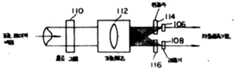
제1a도에서, 레이저팬(10)은 조준된 비임을 비임 스플리터(12)를 통하여 비임을 자기광매체(16)에 집속하는 대물렌즈(14)에 보낸다. 비임 스플리터(12)의 특징은 P 편광광의 80%를 통과시키며 S 편광광의 100%를 반사시킬 것이다. 레이저 다이오드로써 비임스플리터에 대하여 광의 80%의 P 편광이 대물렌즈를 통하여 매체에 전송된다. 나머지 20%는 비임 스플리터에 의해 반사되며 손실된다.In FIG. 1A, the
레이저 비임이 매체의 면에 접속될 때, 발생된 열은 물체를 기록 매체의 자기영역의 지향성이 작은 외부자계에 의해 역으로 되는 온도로 상승시킨다. 결과적으로 정보는 데이터 시퀸스에 따라 레이저 다이오드를 펄스화하여 기록될수 있다.When the laser beam is connected to the surface of the medium, the generated heat raises the object to a temperature reversed by an external magnetic field having low directivity of the magnetic area of the recording medium. As a result, information can be recorded by pulsing the laser diode in accordance with the data sequence.
기록된 정보는 매체에 낮은 파워 레이저 비임을 다시 접속시켜 검색될수 있다. 국소 자기영역 지향성과 광비임의 상호작용은 반사된 비임의 편광이 작은 각도로 회전되게 한다. 즉, 매체와 상호작용후, P 편광광비임은 작은 S 편광성분을 포함한다. 회전광 벡터의 방향은 매체의 자기영역의 지향성에 좌우된다. 따라서, S 성분값은 +1혹은 -1에 따라 양 혹은 음이다. 디지털 넘버에 대하여, -1은 디지털 0에 대응한다,The recorded information can be retrieved by reconnecting the low power laser beam to the medium. The interaction of the local magnetic domain directivity with the light beam causes the polarization of the reflected beam to rotate at small angles. That is, after interaction with the medium, the P polarized light beam contains small S polarized components. The direction of the rotating light vector depends on the directivity of the magnetic region of the medium. Therefore, the S component value is positive or negative depending on +1 or -1. For digital numbers, -1 corresponds to digital 0,
반사비임의 비임 스플리터(12)에 다시 들어갈 때, S 편광성분의 100%가 반사되며 단지 20%의 P 편광성분만이 반사된다. 반사비임의 P 편광성분의 80%가 비임 스플리터(12)를 통하여 레이저 다이오드쪽으로 전송되며 사용되지 않는다. 두 P 및 S 성분이 검출기에 의하여 요구되므로, P 혹은 S 성분의 일부가 손실되어야 하는데 이것은 두 개 모두 비임 스플리터에 의하여 스플리터 오프될수는 없기 때문이다. P 성분은 P 성분에 대해 작은 S 성분의 값을 증가시키기 위해 감소되도록 선택된다. 비임 스플리터(12)에 의해 반사된 비임의 편광방향을 P 성분에 대한 S 성분의 값을 더 증가시키기 위해 비임 스플리터(20)를 통과하기전에 웨이브 플레이트(18)에 의해 45도 정도 더 회전된다. 비임 스플리터(20)는 S 편광성분의 100%가 반사되며 P 편광성분의 100%는 통과되는 성질을 갖는다. 리턴된 비임의 회전방향은 검출기(22) 및 검출기(26)에 의해 검출된 광의 차이를 고려하여 검출될수 있다. 물론 검출기(26)는 4검출기를 구비하고 있으므로 광헤드에 대한 정상적인 방법으로 트랙킹에러 및 초점에러검출을 수행할수 있다.When entering the
제2가능한 실시예가 제2a도에 도시되었다. 레이저펜(10), 대물렌즈(14) 및 자기광매체(16)가 제1a도와 같이 구비되었다. 비임 스플리터(28)는 제1a도의 비임 스플리터(12)와 동일한 성질을 갖는다. 리턴광이 비임 스플리터(28)에 의해 반사될 때, 광은 격자(32)를 통하여 렌즈(30)에 의해 검출기(34,36,38)에 접속된다. 홀로그래픽방법에 의해 바람직하게 제작된 회절격자(32)는 비임 스플리터대신 사용되며, 검출기(34,36,38)에 세회절 비임을 공급한다. 검출기(34,38)앞의 편광자(40,42)는 각각 리턴비임의 편광회전의 방향의 검출을 가능하게 한다. 제2b도로부터 알수 있는 바와같이, 검출기(34,38)는 싱글 검출기인 반면 검출기(36)는 초점 및 트랙킹에러 검출을 위한 사분면 검출기이다.A second possible embodiment is shown in FIG. 2a. The
본 발명은 원래의 레이저펜과 실제적으로 동일한 광경로에 초점에러 및 트랙킹에러 검출기를 둔 레이저펜을 사용한 개량된 자기광헤드이다, 본 발명에서 기억된 정보는 비임 스플리터에 의해서 반사된 비임으로부터 유도되는 반면 전송된 광은 트랙킹에러 및 초점에러 신호를 발생하기 위하여 이용된다.The present invention is an improved magneto-optical head using a laser pen with a focus error and tracking error detector in the same optical path as the original laser pen. The information stored in the present invention is derived from the beam reflected by the beam splitter. On the other hand, the transmitted light is used to generate a tracking error and focus error signal.
종래 장치에서는 서보 전자신호뿐만아니라 기억된 정보는 제1 및 2a도의 비임 스플리터(12) 혹은 비임 스플리터(28)에 의해 반사된 작은양의 광비임에서 유도된다. 더욱이 본 발명은 비임 스플리터가 모든 P 편광성분을 실제적으로 투과시키는 반면 모든 S 편광성분을 실제적으로 반사시키는 종래의 장치에 유사한 80/20형 혹은 비임 스플리터일수 있는 잇점을 지니고 있다. 이것은 레이저 다이오드로부터 장치의 매체로서 광처리량을 향상시킨다. 더욱이, 모든 P 편광을 투과시키며 모든 S 편광을 반사시키기 위한 그러한 비임 스플리터는 통상 더 획득하기 쉬우며 덜 비싸다.In the conventional apparatus, not only the servo electronic signal but also the stored information are derived from a small amount of light beams reflected by the
본 발명의 독특한 레이저펜은 훨씬 작은 광헤드를 감소된 수의 부품들과 사용될수 있게 한다. 레이저펜은 대물렌즈에 보내기 위한 레이저 비임을 발생하기 위한 레이저 다이오드를 포함한다. 리턴 경로에서, 레이저 비임은 회전격자에 충돌하며, 이것은 레이저와 대물렌즈사이에서 홀로그래픽일수 있다. 레이저에서 대물렌즈로의 전향경로상의 회전비임은 사용되지 않지만, 리턴 경로에서 회절비임의 하나는 레이저 다이오드에 바로 인접한 광검출기에 집속된다.The unique laser pen of the present invention allows a much smaller optical head to be used with a reduced number of parts. The laser pen includes a laser diode for generating a laser beam for sending to an objective lens. In the return path, the laser beam impinges on the rotating grating, which can be holographic between the laser and the objective lens. The rotation beam on the forward path from the laser to the objective lens is not used, but one of the diffraction beams in the return path is focused on the photodetector immediately adjacent to the laser diode.
본 발명의 성질 및 장점의 충분한 이해를 돕기위하여 첨부도면과 관련지어 계속되는 상세한 설명이 제공된다.The following detailed description is provided in conjunction with the accompanying drawings in order to provide a thorough understanding of the nature and advantages of the present invention.
제3도는 본 발명에 따른 자기광헤드의 블록도이다. 레이저펜(44)은 조준렌즈(50) 및 홀로그래픽광소자(52)와 함께 레이저 다이오드(46) 및 인접하는 광검출기(48)를 포함한다. 레이저 다이오드는 비임 스플리터(54)의 입사면에 평행한 편광을 갖도록 배열된다(즉, 레이저 비임은 비임 스플리터에 대해 P 편광된다). 비임 스플리터(54)는 모든 P 편광을 실제로 투과시키고 모든 S 편광을 실제로 반사시키는 성질을 갖고 있다. 따라서, 레이저 다이오드로 부터의 모든 P 편광조준광은 매체에 기입 혹은 매체로부터 판독하기 위하여 자기 광매체(58)에 집속하기 위하여 대물렌즈(56)에 비임 스플리터(54)에 의해 전송된다.3 is a block diagram of a magneto-optical head according to the present invention. The laser pen 44 includes a
매체로부터 정보를 검색함에 있어서, 국한된 자기도메인 방향과 광비임의 상호작용은 반사비임의 편광을 작은 각도로 회전되게 한다. 즉, 매체와의 상호작용이후, P 편광 비임은 이제 작은 S 편광성분을 포함한다. 횐전의 광벡터방향은 매체상의 자기 도메인의 방향에 의존한다. 이 방사된 비임이 비임 스플리터(54)에 재진입할 때, 작은 S 편광성분의 100%가 반사되며, P 편광성분의 동일하게 작은 양이 비임 스플리터(54)의 불완전성으로 인하여 반사된다. 결과적으로, 비임 스플리터(56)에 의한 반사후에 광비임의 편광방향은 크게회전된다. 회전방향은 분석기(편광자)(60) 및 광검출기(62)를 사용하면 쉽게 해석될수 있다.In retrieving information from the medium, the interaction of the confined magnetic domain direction with the light beam causes the polarization of the reflection beam to be rotated by a small angle. That is, after interaction with the medium, the P polarization beam now contains a small S polarization component. The optical vector direction of the ear depends on the direction of the magnetic domain on the medium. When this radiated beam reenters the
매체로부터 반사된 광의 P 편광성분의 대부분은 초점에러 및 트랙킹 에러시호를 검출하기 위하여 레이저펜 유니트에 리턴된다. 따라서 본 발명의 이러한 실시예는 사용될 종래기술의 80/20 비임 스플리터보다 더 간단한 비임 스플리터의 사용을 허용한다. 제1a도의 실시예의 여분의 편광 비임 스플리터는 제거된다. 본 발명은 향상된 신호 대 잡음비를 제공하는데, 이는 비임 스플리터(54)에 의해 반사된 광은 기억된 정보를 회복하는 데만 사용되며, 이 광의 어느것도 서보에러를 센싱하기 위해 세분되지 않기 때문이다.Most of the P-polarized components of the light reflected from the medium are returned to the laser pen unit to detect focus errors and tracking error signals. Thus this embodiment of the present invention allows the use of a simpler beam splitter than the prior art 80/20 beam splitter to be used. The extra polarized beam splitter of the embodiment of FIG. 1A is removed. The present invention provides an improved signal-to-noise ratio because the light reflected by the
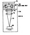
제3도의 레이저펜이 제4도에 도시되었다. 이러한 광헤드배열은 열자기 매체 혹은 랜드 및 피트를 이용한 매체와 같은 상이한 기록매체를 위해 사용될수 있다. 반도체 레이저 및 검출기(68)는 레이저 비임(70)을 조준렌즈(72)에 방사한다. 조준비임은 홀로그램렌즈(74)를 통하여 대물렌즈(76)로 통과된다. 홀로그램렌즈(74)는 반도체 레이저 및 검출기(68)와 조준렌즈(72)사이에도 둘수 있다. 대물렌즈(76)는 비임을 매체(78)에 접속한다. 대물렌즈(76)는 초점 및 트랙킹 작동기(82)에서 코일(80)에 의해 이동될수 있다. 반도체 레이저 및 검출기(68) 조준렌즈(72) 및 홀로그램렌즈(74)는 광헤드의 레이저팬(84)부를 형성한다.The laser pen of FIG. 3 is shown in FIG. Such optical head arrays can be used for different recording media such as thermomagnetic media or media using lands and pits. The semiconductor laser and
제5도는 반도체 레이저 및 광검출기(68)의 전면을 도시한 것이다. 반도체 레이저(86)는 히트싱크(88)위에 장치된다. 사분면 광검출기(90)는 히트싱크(88)면위에 장치된다. 광검출기(92)는 반도체 레이저(86)뒤에 위치되어 반도체 레이저로부터 방사된 광을 측정한다. 광 검출기(92)는 반도체 레이저(86)로 다시 광을 반사하지 않도록 각을 이룬다. 사분면 검출기(90)는 바람직하게는 반도체 레이저(86)의 5밀리미터이내에 있게되며, 바람직하게는 레이저(86)와 동일면의 2mm이내이다, 전형적인 제조공정에 의하면 0.25 내지 0.5mm의 두께 및 따라서 광 검출기 표면과 레이저 다이오드면 사이에 이정도 양의 간격을 갖는 광검출기가 생산된다. 이 간격은 초점에러 발생을 위한 난시파두면과 종래의 렌즈에 유사한 구면파두면을 조합한 홀로그램렌즈로 보상될수 있다. 이것은 검출기를 광헤드의 초점에러범위내에 두어야 한다. 반도체 레이저 및 광검출기(86)의 바람직한 실시예에 대한 더 상세한 설명은 1986년 5월 1일에 출원된 계류중인 출원번호 제 858,411호에 나타나있다.5 shows the front side of the semiconductor laser and
동작에서, 반도체 레이저(86)로 부터의 레이저 비임(70)은 조준렌즈(72)에 의해 조준 혹은 평행하게 된다 이 조준된 비임은 홀로그램렌즈(74)를 통과하여 제로차 회절비임 및 다수의 고차 회절비임을 발생시킨다. 제로차 회절비임은 각을 이루는 것이 아니고 동일경로에서 계속되는 것이며 광헤드의 전향광 경로에서 사용되는 유일한 비임이다. 이 비임은 코일(80)로써 이동될수 있는 대물렌즈(76)에 의해 매체(78)에 접속된다.In operation, the
리턴경로에서, 비임은 다시 제로 및 더 고차회절비임을 발생하는 홀로그램렌즈(74)에 도달한다. 제로차 비임은 레이저로 리턴되며 검출을 위해 사용되지 않는다(일부 종래기술은 반사비임의 강도를 측정하기 위하여 반사비임으로 인한 레이저의 파워 변화를 이용한다. 그러나 이러한 스시템은 이 방식으로 초점 및 트랙킹을 할수 없다). 리턴 경로상의 반사비임은 또한 홀로그래픽렌즈(74)로부터 더 고차인 회절비임을 발생한다. 이러한 고차 회절비임의 하나는 광검출기(90)에 비추어진다. 바람직하게 이것은 대략 10°정도 회절된 제1차 회절비임이다. 이러한 구성은 동일 기계적 구조에 장치되는 반도체 레이저 및 광검출기를 갖는 잇점이 있다. 따라서, 이러한 기계장치의 운동은 광헤드에 의해 수신된 신호에 거의 영향을 미치지않는데 이것은 검출기가 비임이 반도체 레이저의 이동으로 인하여 움직일 동일량 및 방향으로 움직일 것이기 때문이다.In the return path, the beam again reaches the hologram lens 74 which generates zero and higher diffraction beams. The zero difference beam is returned to the laser and not used for detection (some prior art uses the power change of the laser due to the reflection beam to measure the intensity of the reflection beam. However, this system does not focus and track in this manner. Can not). The reflection beam on the return path also generates a higher order diffraction beam from the holographic lens 74. One such higher diffraction beam is illuminated by the photodetector 90. Preferably this is a first order diffraction ratio diffracted by approximately 10 degrees. This configuration has the advantage of having a semiconductor laser and a photodetector installed in the same mechanical structure. Thus, the movement of this mechanism has little effect on the signal received by the optical head because the detector will move in the same amount and direction in which the beam will move due to the movement of the semiconductor laser.
제4도의 실시예는 레이저펜(84)이 초점 및 트랙킹작동기(84)로부터 분리 대체될수 있는 점에서 모듈적이다. 사실 제4도의 초점 및 트랙킹 적동기는 종래기술의 초점 및 트랙킹 작동기와 동일하다.The embodiment of FIG. 4 is modular in that the laser pen 84 can be replaced separately from the focusing and tracking actuator 84. In fact the focusing and tracking actuator of FIG. 4 is identical to the focusing and tracking actuator of the prior art.
광검출기에 충돌하도록 그것을 약간 이동시키기 위한 광의 비임을 회절하는 외에도 홀로그램렌즈(74)는 광검출기와 결합하여 트랙킹 및 초점 기능을 수행하기 위하여 구성될수 있다. 그러한 시스템은 모출원 시리얼넘버 제 938,085호에 기재되어 있다.In addition to diffracting the beam of light to slightly shift it to impinge the photodetector, the hologram lens 74 can be configured to perform tracking and focusing functions in combination with the photodetector. Such a system is described in parent serial number 938,085.
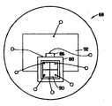
제6도는 본 발명의 다른 실시예의 상단면도이다. 다시, 종래기술로 부터의 이러한 실시예의 특징은 기억된 정보 및 서보에러신호의 개개의 검출이다. 더욱이, 이 실시예에서의 다른 홀로그래픽 비임 스플리터의 사용은 미분검출방법에 의한 리턴비임의 편광회전의 센싱을 허여한다.6 is a top view of another embodiment of the present invention. Again, a feature of this embodiment from the prior art is the individual detection of the stored information and the servo error signal. Moreover, the use of another holographic beam splitter in this embodiment allows the sensing of the polarization rotation of the return beam by the differential detection method.
제6도에서 알수 있는 바와같이. 레이저펜(94)을 P 편광 레이저 비임을 정형광소자(96)를 통하여 80/20편광 비임 스플리터(98)로 향하게 한다. 그곳으로부터 비임은 자기광 매체로의 투사를 위해 도시되지 않은 작동기에 페이지로 부터의 비임을 향하게 하는 터닝미러(100)로 향해진다. 리턴경로에서, 터닝미러(100)는 광을 다시 비임 스플리터(98)로 향하게 한다. P 편광성분의 80%는 비임 스플리터(98)를 통과하여 서보에러신호를 발생하기 위하여 레이저펜(94)으로 리턴된다. 광자기 상호작용에 의해 발생된 S 성분 및 P 성분의 20%는 자기 광검출기 모듈(102)로 행하여 진다.As can be seen in FIG. The
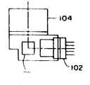
제7도는 작동기(104)로부터 미러(100), 편광 비임 스플리터(98), 및 광소자(96)를 통하여 레이저펜(94)의 광검출기까지의 레이저 비임의 P 성분의 경로를 보여주는 제6도의 선(7-7)을 따라 취한 단면도이다. 제7도는 대물렌즈 및 대물렌즈를 이동시키기 위한 기구를 포함하는 작동기(104)의 접속을 도시한 것이다.FIG. 7 shows the path of the P component of the laser beam from the
제8도는 작동기(104)로부터 미러(100)(도시되지않음) 및 편광 비임 스플리터(98)를 통하여 자기광 검출기(102)까지의 S 성분의 경로를 보여주는 제6도의 선(8-8)을 따라 취한 단면도이다.8 shows line 8-8 of FIG. 6 showing the path of the S component from
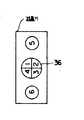
제9도는 제6도의 자기광 검출기(102)의 일실시예이다. 제9도의 실행은 소망되는 80/20 비임 스플리터의 사용을 허여한다. 이 실시예는 제3도의 실시예의 싱글 광검출기와 비교할 때 P 및 S 성분이 전송되므로 두 광검출기(106,108)를 이용한다. 레이저 비임은 조준렌즈(112)를 통과한후에 광검출기(106,108)에 충돌하기 위해 두 회절비임을 발생시키는 홀로그램렌즈(110)를 통과한다. 편광자(114,116)는 각각 광검출기(106,108)앞에 위치된다.9 is one embodiment of the magneto-
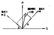
제10도에 도시된 바와같이 편광자(114,116)는 직교 편광성분을 갖는 레이저 비임의 성분을 통과시킨다.As shown in FIG. 10, the
제11도에 도시된 바와같이, 신호벡터(118)는 P 축에 대해 약간 회전될 수 있다. 알려진 바와같이, 분석기(114,116)가 성분(A,B) 방향으로 성분을 통과시키면, 광검출기는 상이한 진폭신호를 검출할 것이다. P 혹은 S 성분, 혹은 0.4도 기대 회전 벡터의 성분을 위해 분석기를 정확하게 정렬시키기가 가능하지 않을수도 있음을 주의하자. 그러나, 그러한 정확한 정렬은 필요하지 않다. 따라서, 광검출기의 값간의 차이는 검출된 신호를 제공하며, 그것은 성분(A)이 B보다 크면 1이며, 작으면 -1이다.As shown in FIG. 11, the
당분야의 전문가에게 이해될 것인바. 본 발명은 그 취지나 본질적인 특성을 벗어나지 않으면 기타의 특정형태로 구현될수 있다. 예를들면, 제9도의 편광자는 직교할 필요는 없다. 부가하면, 광검출기의 하나는 홀로그램렌즈(100)로부터 0차(축에서) 1회절비임을 검출하도록 위치될수 있다. 따라서 본 발명의 바람직한 실시예에 대한 기재는 예증적인 것이며, 이하 청구범위에 기재된 본 발명의 취지에 대한 제한이 아니다.As will be understood by experts in the field. The present invention can be embodied in other specific forms without departing from the spirit or essential characteristics thereof. For example, the polarizer of FIG. 9 need not be orthogonal. In addition, one of the photodetectors may be positioned to detect a zero diffraction beam (in the axis) from the
Claims (6)
Translated fromKoreanApplications Claiming Priority (2)
| Application Number | Priority Date | Filing Date | Title |
|---|---|---|---|
| US141,459 | 1988-01-20 | ||
| US07/141,459US4918675A (en) | 1986-12-04 | 1988-01-20 | Magneto-optical head with separate optical paths for error and data detection |
Publications (2)
| Publication Number | Publication Date |
|---|---|
| KR890012285A KR890012285A (en) | 1989-08-25 |
| KR910006661B1true KR910006661B1 (en) | 1991-08-30 |
Family
ID=22495791
Family Applications (1)
| Application Number | Title | Priority Date | Filing Date |
|---|---|---|---|
| KR1019890000347AExpiredKR910006661B1 (en) | 1988-01-20 | 1989-01-14 | Magneto-opticla head |
Country Status (4)
| Country | Link |
|---|---|
| US (1) | US4918675A (en) |
| EP (1) | EP0325104A3 (en) |
| JP (1) | JPH06101156B2 (en) |
| KR (1) | KR910006661B1 (en) |
Families Citing this family (24)
| Publication number | Priority date | Publication date | Assignee | Title |
|---|---|---|---|---|
| US5155718A (en)* | 1988-01-25 | 1992-10-13 | Olympus Optical Co., Ltd. | Optical record medium reading apparatus having a de-focussed light beam projected on an optical record medium |
| US5315574A (en)* | 1988-10-28 | 1994-05-24 | Matsushita Electric Industrial Co., Ltd. | Optical head with polarized beam hologram |
| US4984229A (en)* | 1988-11-18 | 1991-01-08 | Polaroid Corporation | Autofocus system |
| FR2646245B1 (en)* | 1989-04-25 | 1991-06-14 | Thomson Csf | OPTICAL READING DEVICE FOR OPTICAL RECORDING MEDIUM |
| DE69031366T2 (en)* | 1989-06-26 | 1998-04-09 | Nippon Electric Co | Optical system |
| US5218582A (en)* | 1990-12-03 | 1993-06-08 | Eastman Kodak Company | Magneto-optic readout using a polarization-preserving optical guide |
| KR950013702B1 (en)* | 1993-07-15 | 1995-11-13 | 엘지전자주식회사 | Optical pick up apparatus of optical disk |
| JPH07114746A (en)* | 1993-08-25 | 1995-05-02 | Sony Corp | Optical device |
| JP3541416B2 (en)* | 1994-03-08 | 2004-07-14 | ソニー株式会社 | Optical device |
| US5852591A (en)* | 1994-04-23 | 1998-12-22 | Sony Corporation | Magneto-optical recording medium and head unit for a magneto-optical recording medium |
| JP3029541B2 (en)* | 1994-12-19 | 2000-04-04 | シャープ株式会社 | Optical pickup device |
| JPH08235663A (en)* | 1995-02-24 | 1996-09-13 | Sony Corp | Optical element |
| JP3544239B2 (en)* | 1995-03-04 | 2004-07-21 | ソニー株式会社 | Optical pickup and optical recording medium reproducing apparatus |
| EP0731456A2 (en)* | 1995-03-04 | 1996-09-11 | Sony Corporation | Optical pickup and optical recording medium reproducing apparatus |
| US5790291A (en)* | 1995-12-07 | 1998-08-04 | Lucent Technologies Inc. | Beam steering and tracking of laser communication links by dual-quadrant tracker and photodiode assembly |
| JP3732268B2 (en)* | 1996-02-28 | 2006-01-05 | 富士通株式会社 | Optical head for optical disk device |
| JP3439903B2 (en)* | 1996-03-11 | 2003-08-25 | 富士通株式会社 | Optical head for optical disk device |
| US5991249A (en)* | 1997-07-29 | 1999-11-23 | Hoetron, Inc. | Optical track sensing device |
| FR2802696B1 (en)* | 1999-12-17 | 2002-07-19 | Thomson Csf | MAGNETO OPTICAL READER OPTIMIZED BY THE INCIDENT LIGHT POLARIZER |
| KR100754160B1 (en)* | 2001-06-30 | 2007-09-03 | 삼성전자주식회사 | Optical Disc Device and Wobble Signal Playback Method |
| US6723980B2 (en) | 2001-07-16 | 2004-04-20 | Wai-Hon Lee | Position sensor with grating to detect moving object with periodic pattern |
| US20040090874A1 (en)* | 2002-11-08 | 2004-05-13 | Kunjithapatham Balasubramanian | Apparatus and method for effective reduction of a laser beam spot size |
| JP2005182960A (en)* | 2003-12-22 | 2005-07-07 | Sharp Corp | Optical integrated unit for magneto-optical and optical pickup device for magneto-optical |
| JP5227926B2 (en)* | 2009-09-16 | 2013-07-03 | 株式会社日立メディアエレクトロニクス | Optical pickup device and optical disk device |
Family Cites Families (16)
| Publication number | Priority date | Publication date | Assignee | Title |
|---|---|---|---|---|
| JPS57111843A (en)* | 1980-12-27 | 1982-07-12 | Canon Inc | Vertical magnetic reading optical system |
| US4504939A (en)* | 1981-12-10 | 1985-03-12 | Discovision Associates | Storage medium track pitch detector |
| US4462095A (en)* | 1982-03-19 | 1984-07-24 | Magnetic Peripherals Inc. | Moving diffraction grating for an information track centering system for optical recording |
| JPS58203646A (en)* | 1982-05-21 | 1983-11-28 | Canon Inc | magneto-optical reproducing device |
| US4558440A (en)* | 1982-08-19 | 1985-12-10 | Canon Kabushiki Kaisha | System for recording patterns of magnetically recorded information by utilizing the magneto-optic effect |
| US4695992A (en)* | 1983-01-31 | 1987-09-22 | Canon Kabushiki Kaisha | Optical information recording-reproducing apparatus in which the relative position of a primary beam and secondary beams on recording medium is varied during recording and reproduction of information |
| JP2504734B2 (en)* | 1983-11-08 | 1996-06-05 | シャープ株式会社 | Optical device of magneto-optical storage device |
| US4670869A (en)* | 1984-01-03 | 1987-06-02 | Magnetic Peripherals Inc. | Switching laser beam apparatus with recombined beam for recording |
| US4689481A (en)* | 1984-06-14 | 1987-08-25 | Nec Corporation | Focus error detector and optical head using the same |
| KR920007294B1 (en)* | 1984-06-29 | 1992-08-29 | 가부시끼가이샤 히다찌세이사꾸쇼 | Optical head for magneto-optical memory |
| JPS61160845A (en)* | 1985-01-09 | 1986-07-21 | Nippon Kogaku Kk <Nikon> | Optical disk recording and reproducing device |
| EP0216341B1 (en)* | 1985-09-27 | 1990-07-04 | Sharp Kabushiki Kaisha | Tracking system for optical disc memory |
| JPS6284456A (en)* | 1985-10-08 | 1987-04-17 | Mitsubishi Electric Corp | Magneto-optical recording/reproducing device |
| JPS62112246A (en)* | 1985-11-11 | 1987-05-23 | Sharp Corp | pick up device |
| US4794585A (en)* | 1986-05-06 | 1988-12-27 | Lee Wai Hon | Optical head having a hologram lens and polarizers for use with magneto-optic medium |
| NL8601974A (en)* | 1986-08-01 | 1988-03-01 | Philips Nv | DEVICE FOR SCANNING A RADIATION-REFLECTING INFORMATION SHEET WITH OPTICAL RADIATION. |
- 1988
- 1988-01-20USUS07/141,459patent/US4918675A/ennot_activeExpired - Lifetime
- 1989
- 1989-01-04EPEP19890100090patent/EP0325104A3/ennot_activeWithdrawn
- 1989-01-14KRKR1019890000347Apatent/KR910006661B1/ennot_activeExpired
- 1989-01-20JPJP1010118Apatent/JPH06101156B2/ennot_activeExpired - Lifetime
Also Published As
| Publication number | Publication date |
|---|---|
| JPH06101156B2 (en) | 1994-12-12 |
| US4918675A (en) | 1990-04-17 |
| KR890012285A (en) | 1989-08-25 |
| EP0325104A2 (en) | 1989-07-26 |
| EP0325104A3 (en) | 1991-06-12 |
| JPH01282764A (en) | 1989-11-14 |
Similar Documents
| Publication | Publication Date | Title |
|---|---|---|
| KR910006661B1 (en) | Magneto-opticla head | |
| US4794585A (en) | Optical head having a hologram lens and polarizers for use with magneto-optic medium | |
| CA1232353A (en) | Optical signal recorders employing two lasers and methods therefor | |
| US4965780A (en) | Magneto-optical data recording device using a wavelength and polarization-sensitive splitter | |
| CA1159149A (en) | Optical device for recording and reading on a data carrier | |
| US5712842A (en) | Optical pick-up device | |
| US4894815A (en) | Optical head for reading information from a magnetooptic recording medium | |
| US4789977A (en) | Optical data recording device | |
| JPS6332743A (en) | Optical head | |
| JPS6227456B2 (en) | ||
| US5249167A (en) | Optical pickup apparatus which includes a plate-like element for splitting a returning light beam into different light beams having different focussing point | |
| US5488592A (en) | Optical pickup device for magneto-optical disc reproducing system | |
| US6125091A (en) | Optical pickup apparatus for use with various types of optical disks | |
| US5119352A (en) | Magneto optic data storage read out apparatus and method | |
| JP3439903B2 (en) | Optical head for optical disk device | |
| KR100893722B1 (en) | Optical scanning device | |
| JP2812764B2 (en) | Optical head for optical disk device | |
| JPH0242647A (en) | optical pickup device | |
| JP3356314B2 (en) | Magneto-optical detector, magneto-optical detector and magneto-optical disk device | |
| JP2604368B2 (en) | Birefringence measurement device | |
| JPS639305B2 (en) | ||
| JPH02226526A (en) | Optical head | |
| JPH0229945A (en) | Light pickup | |
| JPS62172539A (en) | Tracking control method for optical information reader | |
| JPH0253244A (en) | Optical heads for magneto-optical recording devices |
Legal Events
| Date | Code | Title | Description |
|---|---|---|---|
| A201 | Request for examination | ||
| PA0109 | Patent application | Patent event code:PA01091R01D Comment text:Patent Application Patent event date:19890114 | |
| PA0201 | Request for examination | Patent event code:PA02012R01D Patent event date:19890114 Comment text:Request for Examination of Application | |
| PG1501 | Laying open of application | ||
| G160 | Decision to publish patent application | ||
| PG1605 | Publication of application before grant of patent | Comment text:Decision on Publication of Application Patent event code:PG16051S01I Patent event date:19910731 | |
| E701 | Decision to grant or registration of patent right | ||
| PE0701 | Decision of registration | Patent event code:PE07011S01D Comment text:Decision to Grant Registration Patent event date:19911125 | |
| NORF | Unpaid initial registration fee | ||
| PC1904 | Unpaid initial registration fee |