Movatterモバイル変換


[0]ホーム

URL:


KR910003382B1 - Semiconductor memory device with register - Google Patents

Semiconductor memory device with register
Download PDF

Info

Publication number
KR910003382B1
KR910003382B1KR1019880007727AKR880007727AKR910003382B1KR 910003382 B1KR910003382 B1KR 910003382B1KR 1019880007727 AKR1019880007727 AKR 1019880007727AKR 880007727 AKR880007727 AKR 880007727AKR 910003382 B1KR910003382 B1KR 910003382B1
Authority
KR
South Korea
Prior art keywords
data
register
operation mode
supplied
signal
Prior art date
Legal status (The legal status is an assumption and is not a legal conclusion. Google has not performed a legal analysis and makes no representation as to the accuracy of the status listed.)
Expired
Application number
KR1019880007727A
Other languages
Korean (ko)
Other versions
KR890001085A (en
Inventor
후미오 바바
가즈야 고바야시
세이지 에노모또
히로아끼 오가와
Original Assignee
후지쓰 가부시끼가이샤
야마모도 다꾸마
후지쓰 브이엘에스아이 가부시끼가이샤
나까노 히로유끼
Priority date (The priority date is an assumption and is not a legal conclusion. Google has not performed a legal analysis and makes no representation as to the accuracy of the date listed.)
Filing date
Publication date
Application filed by 후지쓰 가부시끼가이샤, 야마모도 다꾸마, 후지쓰 브이엘에스아이 가부시끼가이샤, 나까노 히로유끼filedCritical후지쓰 가부시끼가이샤
Publication of KR890001085ApublicationCriticalpatent/KR890001085A/en
Application grantedgrantedCritical
Publication of KR910003382B1publicationCriticalpatent/KR910003382B1/en
Expiredlegal-statusCriticalCurrent

Links

Images

Classifications

Landscapes

Abstract

Translated fromKorean

내용 없음.No content.

Description

Translated fromKorean
레지스터를 구비한 반도체 메모리 장치Semiconductor memory device with register

제 1 도는 본 발명에 대한 바람직한 실시예의 블록도.1 is a block diagram of a preferred embodiment of the present invention.

제 2 도는 제 2a 도 내지 2c 도의 결합방식을 나타내는 도면.2 is a view showing a coupling method of Figures 2a to 2c.

제 2a 도 내지 2c 도는 제 1도 에 나타난 실시예의 회로도.2a to 2c are circuit diagrams of the embodiment shown in FIG.

제 3 도는 제 1도 및 2a 도에 나타난 모드 판별 회로도.3 is a mode discrimination circuit diagram shown in FIGS. 1 and 2a.

제 4 도는 제 1도 및 2a 도에 나타난 센스 증폭기의 접속/차단과 입력/출력 게이트 제어 회로도.4 is an input / output gate control circuit diagram of connection / disconnection of the sense amplifiers shown in FIGS. 1 and 2a.

제 5 도는 제 2a 도에 나타난 1/4열 어드레스 디코더 회로.5 is a quarter-column address decoder circuit shown in FIG. 2A.

제 6 도는 열 디코더와 데이터 버스 간의 연결을 나타내는 도면.6 shows a connection between a column decoder and a data bus.

제 7 도는 열 디코더 및 센스 증폭기 및 입력/출력 게이트에 대한 회로도.7 is a circuit diagram for a column decoder and sense amplifiers and input / output gates.

제 8 도는 실시예에 사용된 신호들의 신호상태를 나티내는 도면.8 is a diagram showing signal states of signals used in the embodiment.

제 9a 도 내지 9(i) 도는 실시예에서 레지스터 동작에 사용된 신호파형도.9A to 9I are signal waveform diagrams used for register operation in the embodiment.

제 10a 도 내지 10(i) 도는 실시예에서 정상동작에 사용된 신호파형도.10A to 10I are signal waveform diagrams used for normal operation in the embodiment.

제 11a 도 내지 11(g) 도는 실시예에서 블록동작모드에 사용된 신호 파형도,및11A to 11G are signal waveform diagrams used in the block operation mode in the embodiment, and

제 12a 도 내지 12(g) 도는 실시예에서 판독전송모드와 기입전송모드의 신호 파형도.12A to 12G are signal waveform diagrams of a read transfer mode and a write transfer mode in the embodiment.

본 발명은 일반적으로 반도체 메모리 장치에 관한 것이며, 특히 메모리셀과 함께 레지스터를 구비하는 반도체 메모리 장치에 관한 것이다. 특히, 본 발명은 영상처리용 메모리로서 사용하기에 적합한 레지스터를 구비한 랜덤 억세스 메모리에 관한 것이다.BACKGROUND OF THEINVENTION 1. Field of the Invention The present invention generally relates to semiconductor memory devices, and more particularly to semiconductor memory devices having registers together with memory cells. In particular, the present invention relates to a random access memory having a register suitable for use as an image processing memory.

일반적으로, 종래의 랜덤 억섹스 메모리 장치의 메모리셀에 관한 데이터 기입 및 판독 동작은 예를들면 1.4 또는 8비트로 구성되는 소정데이타 단위로 실행된다. 그러나 그러한 동작은 고객의 다양한 요구를 충족할 수 없다. 특히, 영상처리 부분에서는, 매우 큰 기억용량을 가지고 고속으로 데이터를 전송할 수 있는 RAM장치의 사용이 요구된다. 현재, 상기 요구를 만족시킬수 있는 RAM장치가 제안되고 있다. 예를 들어, 영상처리용으로 독점개발된 64Kbit 및 256Kbit 다이나믹 랜덤 억섹스 메모리가 입수가능하다. 하나의 반도체 장치에 대한 메모리 용량이 증가함에 따라, 고속으로 데이터를 전송하고 또한 영상처리를 더욱 간단하게 수행할수 있는 고급 랜덤 억섹스 메모리에 대한 또다른 요구가 있다. 이런 관점에서, 현재 메모리셀과 함께 레지스터를 내장함으로써 특수기능을 부여한 RAM장치의 개발이 매우 활발헤지고 있다. 예를 들어, 내장 레지스터는 마스크 레지스터로 사용될 수도 있어, 일 비트 단위로 메모리셀에 기입되도록 데이터를 제어할 수있다. 더우기, 내장 레지스터의 사용은, 일 기준 사이클내에서, RAM장치의 입력핀수를 초과하는 비트의 조정수로 조합된 데이터를 갱신하는 것이 가능하다. 이러한 특수기능을 갖는 RAM장치는 복잡한 영상처리를 고속으로 수행할수 있다. 그러나, 내장 레지스터에 기억된 데이터를 외부회로로 전송하고 내장 레지스터의 내용을 즉시 인식하는 것은 불가능하다는 것을 주의하라.In general, data writing and reading operations for a memory cell of a conventional random access memory device are performed in units of predetermined data consisting of, for example, 1.4 or 8 bits. However, such an operation cannot meet the various needs of the customer. In particular, in the image processing portion, the use of a RAM device capable of transferring data at high speed with a very large storage capacity is required. At present, a RAM device capable of satisfying the above requirements has been proposed. For example, 64Kbit and 256Kbit dynamic random access memory, exclusively developed for image processing, are available. As the memory capacity of one semiconductor device increases, there is another demand for an advanced random access memory that can transfer data at high speed and more easily perform image processing. In view of this, the development of RAM devices with special functions by incorporating registers together with memory cells is very active. For example, the built-in register may be used as a mask register, so that data can be controlled to be written to the memory cell in one bit unit. Moreover, the use of the built-in registers can update the combined data with the number of adjustments of bits exceeding the number of input pins of the RAM device within one reference cycle. A RAM device having such a special function can perform complex image processing at high speed. However, note that it is not possible to transfer data stored in an internal register to an external circuit and immediately recognize the contents of the internal register.

그러므로, RAM장치의 동작을 유효하게 하는 것은 매우 복잡하다.Therefore, validating the operation of the RAM device is very complicated.

예를 들어, 잘못된 동작이 내장 레지스터 또는 데이터 자체에서 발생하였는지를 발견하기가 어렵다. 이런 불이익은 RAM장치 개발 기간이 증가, 더욱 복잡해진 검사과정, 및 단가의 상승을 가져온다. 따라서, 본 발명의 통상적인 목적은 종래 반도체의 불이익이 제거된 레지스터를 구비하는 새롭고 유용한 반도체 메모리장치를 제공하기 위함이다.For example, it is difficult to find out whether the wrong operation has occurred in the built-in registers or the data itself. This disadvantage leads to an increase in the development period of the RAM device, a more complicated inspection process, and an increase in unit cost. Accordingly, it is a general object of the present invention to provide a new and useful semiconductor memory device having a register that eliminates the disadvantages of conventional semiconductors.

본 발명의 더욱 특수한 목적은 데이터를 기입 레지스터에 기입 및 판독할수 있는 레지스터를 구비한 반도체 메모리장치를 제공하기 위함이다.A more special object of the present invention is to provide a semiconductor memory device having a register capable of writing and reading data into a write register.

그러므로, DRAM장치의 동작에 대한 유효검사는 쉽게 수행될 수 있다.Therefore, the validity check on the operation of the DRAM device can be easily performed.

게다가, RAM장치 개발기간을 줄일수 있고, 공급 검사에서의 효율을 개선할 수 있다.In addition, the RAM development time can be shortened and the efficiency in supply inspection can be improved.

본 발명의 상기 목적들은 일련의 메모리셀을 갖는 메모리셀 어레이 : 데이터 버스 : 메모리셀 어레이와 대응 데이터 버스간에 제공된 입력/출력회로 : 소정데이터를 기억하는 레지스터 : 및 데이터 버스와 레지스터 간에 연결된 전송게이트로 구성된 레지스터를 갖는 것을 특징으로 하는 메모리 장치에 의해 이루어질수 있다.The object of the present invention is to provide a memory cell array having a series of memory cells; a data bus; an input / output circuit provided between a memory cell array and a corresponding data bus; a register for storing predetermined data; and a transfer gate connected between the data bus and a register. It can be made by a memory device characterized by having a configured register.

그 장치는 또한 데이터 버스상에서 데이터를 외부회로에 전송하는 제1데이타 버퍼 : 및 외부회로로부터 공급된 데이터 버스로 전송하는 제 2데이터 버퍼를 포함한다.The apparatus also includes a first data buffer for transferring data to an external circuit on the data bus and a second data buffer for transferring to a data bus supplied from the external circuit.

상기 소자들에 덧붙여, 그 장치는 데이터 버스로부터 입력/출력회로를 차단하고 제 1동작모드에서 전송게이트를 오픈시키는 제어회로와 데이터버스로부터 입력/출력회로를 연결하고 제 2동작모드에서 전송게이트를 온 시키는 제어회로를 포함한다.In addition to the above elements, the device connects an input / output circuit from the data bus with a control circuit which disconnects the input / output circuit from the data bus and opens the transmission gate in the first mode of operation and connects the transmission gate in the second mode of operation. It includes a control circuit to turn on.

제 1동작모드에서, 데이터 판독 또는 기입동작은 데이터 버스 및 제 1, 제 2버퍼중의 하나를 통하여 메모리셀 어레이와 외부회로 사이에서 수행된다.In the first mode of operation, a data read or write operation is performed between the memory cell array and the external circuit via the data bus and one of the first and second buffers.

선택적으로 제 2동작모드에서는, 데이터 판독 또는 기입 동작이 전송게이트, 데이터 버스 및 제 1, 제 2버퍼중 하나를 통하여 레지스터와 외부회로 사이에서 수행된다.Optionally in the second mode of operation, a data read or write operation is performed between the register and the external circuit via the transfer gate, the data bus and one of the first and second buffers.

본 발명의 다른 목적, 특징 및 이점은 첨부된 도면과 관련된, 이후의 상세한 설명에서 명백헤 질 것이다.Other objects, features and advantages of the present invention will become apparent from the following detailed description taken in conjunction with the accompanying drawings.

제 1 도는 본 발명의 바람직한 실시예의 블록도이다. 설명된 구성은 영상처리용으로 개발된 4비트 구조의 RAM장치이다.1 is a block diagram of a preferred embodiment of the present invention. The described configuration is a 4-bit RAM device developed for image processing.

제 1 도를 참조하면, RAM장치는 4메모리셀 어레이(1 내지 4)를 포함하며, 그것의 각각은 256Kbit의 메모리용량을 갖는다. RAM장치는 또한 어드레스 비트(AO내지 AN)(설명된 실시예에서는 N-7 이다)로 이루어진 어드레스 신호를 기입하는 어드레스 버퍼(5), 행 어드레스 디코더(6), 열 어드레스 디코더(7), 센스 증폭기와 입력/출력게이트(I/O게이트)를 각각 포함하는 블록으로 구성된다.Referring to FIG. 1, the RAM device includes fourmemory cell arrays 1 to 4, each of which has a memory capacity of 256 Kbit. The RAM device also has anaddress buffer 5, arow address decoder 6, acolumn address decoder 7 which writes an address signal consisting of address bits AO to AN (in the embodiment described, N-7). And a block including a sense amplifier and an input / output gate (I / O gate), respectively.

열어드레스 디코더(7 내지 10) 및 블록(11 내지 14)은 메모리셀 어레이와 각각 결합된다.The open-dress decoders 7 to 10 and blocks 11 to 14 are combined with the memory cell array, respectively.

데이터레지스터(15 내지 18)는 메모리셀 어레이(1 내지 4)로부터 출력된 병렬 데이터를 1행마다 대응하는 직렬 데이터로 변환된다.The data registers 15 to 18 convert parallel data output from thememory cell arrays 1 to 4 into corresponding serial data for each row.

포인터(19 내지 22)는 데이터가 데이터 레지스터로부터 직렬형태로 판독될 때 제공할수 있다.Thepointers 19 to 22 can provide when data is read in serial form from the data register.

직렬 입력/출력 버퍼(23 내지 26)는 메모리셀 어레이(1 내지 4)로부터 데이터 판독과 일행단위로 데이터를 기입하도록 사용된다. 직렬 입력/출력 버퍼(23 내지 26)는 전송제어기(27)로부터 공급되는 직렬 포인트 인에이블 신호

Figure kpo00001
와 타이밍 신호(TIM)에 의해 제어된다. 부재번호(SDO내지 SD)는 직렬데이터를 표시한다. 전송 제어기(27)는 스크 모드 인에이블/출력 인에이블
Figure kpo00002
와 전송 인에이블/출력 인에이블신호
Figure kpo00003
를 입력하며, 두 신호는 중앙처리장치처럼 메모리 제어회로(도시되지 않음)로부터 공급된다. 전송제어기는(27)는 메모리셀 어레이(1 내지 4)와 데이터 레지스터(15 내지 18)간에 각각 테이타 전송동작을 제어한다. 더우기 전송제어기(27)는 직렬 입력/출력 버퍼의 입력 및 출력 동작을 제어한다.The serial input /output buffers 23 to 26 are used to read data from thememory cell arrays 1 to 4 and to write data in one row. The serial input /output buffers 23 to 26 are serial point enable signals supplied from thetransmission controller 27.
Figure kpo00001
And timing signal TIM. Absence numbers SDO to SDI indicate serial data.Transmission Controller 27 Enables Scratch Mode Enable / Output
Figure kpo00002
And Transmission Enable / Output Enable Signals
Figure kpo00003
And two signals are supplied from a memory control circuit (not shown) as the central processing unit. Thetransfer controller 27 controls the data transfer operation between thememory cell arrays 1 to 4 and the data registers 15 to 18, respectively. Moreover, thetransmission controller 27 controls the input and output operations of the serial input / output buffer.

기입 클록 발생기(28)는 마스크 모드 인에이블/출력 인에이블신호

Figure kpo00004
를 입력하며 기입클록신호를 발생하며, 기입클록신호는 입력/출력 버퍼에 공급된다.Write clock generator 28 provides mask mode enable / output enable signals.
Figure kpo00004
Is input to generate a write clock signal, and the write clock signal is supplied to the input / output buffer.

클록발생기(29)는 메모리 제어회로로부터 공급된 행 어드레스 스트로우브 신호

Figure kpo00005
와 열 어드레스 스트로우브 신호
Figure kpo00006
를 입력하며, 수신된 신호로부터 내부 클록신호(ψA및 ψB) 를 발생한다. 리프레시 어드레스 카운터(30)는 클록 발생기(29)로부터 공급된 카운트 신호를 계수하고, 카운터내에 데이터를 유지하기 위하여 메모리셀 어레이(1 내지 4)를 리프레시하는 어드레스 신호를 어드레스 버퍼(5)에 공급한다.Theclock generator 29 is a row address strobe signal supplied from the memory control circuit.
Figure kpo00005
And column address strobe signals
Figure kpo00006
Is input, and generates internal clock signals ψA and ψB from the received signals. Therefresh address counter 30 counts the count signal supplied from theclock generator 29 and supplies an address signal to theaddress buffer 5 for refreshing thememory cell arrays 1 to 4 in order to hold data in the counter. .

선택기(31 내지 34)는 칼라데이터 레지스터(30 및 40)로부터 공급된 데이터와 외부회로에서 공급된데이타(DQ0내지 DQ3)로부터 일 데이터를 선택하도록 사용된다.Theselectors 31 to 34 are used to select one data from data supplied from thecolor data registers 30 and 40 and data DQ0 to DQ3 supplied from an external circuit.

입력/출력 버퍼(35 내지 38)는 정상동작모드/블록동작모드 스위칭 신호(B) 및 레지스터 동작모드 세팅신호(R)후에 기술됨, 전송 인에이블/출력 인에이블 신호, 및 기입 클록 발생기(28)로부터 공급된 기입 클록 신호에 의하여 제어된다.The input /output buffers 35 to 38 are described after the normal operation mode / block operation mode switching signal B and the register operation mode setting signal R, the transfer enable / output enable signal, and the write clock generator 28. Control by the write clock signal supplied from

칼라 데이터 레지스터(39(#1) 및 40(#2)들은 영상처리 동안 연속적으로 사용되는 칼라 데이터를 기억하는데 사용된다. 마스크 레지스터(41)은 외부회로(도시되지 않음)에서 공급된 데이터(DQ 내지 DQ3)에 관한, 일 비트 단위당, 기입동작을 금지하는 기능을 갖는다.The color data registers 39 (# 1) and 40 (# 2) are used to store color data which are used continuously during image processing, and themask register 41 is provided with data DQ supplied from an external circuit (not shown). To DQ3), a function for inhibiting the write operation per one bit unit.

제어회로(42)는 본 발명의 [실시예]에 따라 RAM장치에 제공된다. 제어회로(42)는 칼라 데이터 레지스터(39 및 40)와 마스크 레지스터(41)를 구성하는 내장 레지스터에 기억된 데이터를 외부회로로 판독되도록 하며 외부회로에서 내장 레지스터에 공급되는 데이터를 기입하는 기능을 갖는다.Thecontrol circuit 42 is provided to the RAM device according to the [embodiment] of the present invention. Thecontrol circuit 42 reads the data stored in the internal registers constituting the color data registers 39 and 40 and themask register 41 into an external circuit, and writes data supplied from the external circuit to the internal registers. Have

제어회로(42)는 메모리 제어회로부터 공급되는 특정기능신호(SF)와 로우액티브 판독 인에이블 신호

Figure kpo00007
로 공급된다. 제어회로(42)는 또한 로우어드레스 신호의 일부인 로우어드레스 비트(RA0,RA1)가 구비되어 있다. 제어회로(42)는 클록 발생기(29)로부터 발생된 클록신호(ψA및 ψB) 로 더 공급된다. 제어회로(42)는 레지스터 동작모드 세팅신호(R)와 특정기능신호(SF) 및 기입 인에이블 신호
Figure kpo00008
로부터 정상동작모드/블록동작모드 스위칭신호를 발생하며, 클록신호(ψA및 ψB)와 동기하여 그 신호들을 출력한다. 레지스터 동작모드 세팅신호(R)와 정상동작모드/블록동작모드 스위칭 신호(B)는 열 디코더(7)에 공급되고, 또한 타이밍 조정회로를 통하여 입력/출력 버퍼(35 내지 38)로 공급된다.Thecontrol circuit 42 has a specific function signal SF and a low active read enable signal supplied from the memory control circuit.
Figure kpo00007
Is supplied. Thecontrol circuit 42 is also provided with low address bits RA0 , RA1 which are part of the low address signal. Thecontrol circuit 42 is further supplied with the clock signals ψA and ψB generated from theclock generator 29. Thecontrol circuit 42 includes a register operation mode setting signal R, a specific function signal SF, and a write enable signal.
Figure kpo00008
A normal operation mode / block operation mode switching signal is generated, and the signals are output in synchronization with the clock signals ψA and ψB. The register operation mode setting signal R and the normal operation mode / block operation mode switching signal B are supplied to thecolumn decoder 7 and also to the input /output buffers 35 to 38 through the timing adjustment circuit.

레지스터 동작모드 세팅신호(R)가 하이레벨로 유지될 때(이후에 간단히 "H"로 언급됨), 기입동작 또는 판독동작은 레지스터(39, 40 및 41)와 외부회로 사이에서 수행될수 있다.When the register operation mode setting signal R is held at a high level (hereinafter simply referred to as "H"), a write operation or a read operation can be performed between theregisters 39, 40, and 41 and the external circuit.

정상동작모드/블록동작모드 스위칭 신호(B)는 데이터를 메모리셀 어레이(1 내지 4)로 기입하거나 또는 데이터를 그들로부터 판독하는 시간에서 선택되도록 모드를 결정한다.The normal operation mode / block operation mode switching signal B determines the mode to be selected at the time of writing data into thememory cell arrays 1 to 4 or reading data from them.

본 발명의 실시예에서, 정상동작모드/블록동작모드 스위칭 신호에 의해 선택될수 있는 두 개의 모드가 있는데 그 하나는 정상모드이고 다른 하나는 블록기입모드이다.In the embodiment of the present invention, there are two modes that can be selected by the normal operation mode / block operation mode switching signal, one of which is a normal mode and the other is a block writing mode.

이 모드들은 이후에 상세히 설명될 것이다. 이 제어회로(42)는 또한 레지스터 선택신호(a1,a2, 및 a3)를 발생하는데 그 신호들은 레지스터(39, 40 및 41)와 각각 결합된 전송게이트(T1, T2및 T3)에 공급된다.These modes will be described in detail later. Thiscontrol circuit 42 also generates register select signals a1 , a2 , and a3 , which signals are coupled to the transfer gates T1 , T2, and T respectively associated with theregisters 39, 40, and 41, respectively.3 ) is supplied.

레지스터 동작모드가 선택될 때, 레지스터(39, 40 및 41)중의 하나는 래지스터 선택신호(a1,a2, 및 a3)에 의해 선택된다. 제 2a 도 내지 2c 도는 제 1 도에 나타난 구성을 보여주는 상세한 블록도이다. 우선 제 2a 도를 참조하면, 선택기(31)는 4-비트 데이터(DQ0내지 DQ3)중에서 제 1 데이타 비트(DQ0)에 설치된다.When the register operation mode is selected, one of theregisters 39, 40, and 41 is selected by the register selection signals a1 , a2 , and a3 . 2a to 2c are detailed block diagrams showing the configuration shown in FIG. Referring first to FIG. 2A, theselector 31 is provided in the first data bit DQ0 among the 4-bit data DQ0 to DQ3 .

선택기(31)는 선택기(S1)의 출력, 칼라 레지스터(39)의 최하위 디지트 비트(C10), 및 칼라 레지스터(40)의 최하위 디지트 비트(C20)사이에서 한 개의 신호를 선택한다.Theselector 31 selects one signal between the output of the selector S1 , the least significant digit bit C10 of thecolor register 39, and the least significant digit bit C20 of thecolor register 40.

선택기(32, 33 및 34)는 4-비트 데이터(DQ0내지 DQ3)의 제 2, 제 3 및 제 4데이타 비트에 설치된다. 선택기(32, 33 및 34)는 선택기(31)와 유사한 기능을 갖는다. 레지스터 디코더(D2)는 제 1데이타 비트(DQ0)값에 의하여 입력신호중 어느하나가 선택되는지를 결정한다. 레지스터 디코더(D2)는 레지스터 동작모드 세팅신호(R)가 "H'에 세트될 때 활성화된다.센스 버퍼(351) 및 기입증폭기(352)는 칼라 레지스터의 최하위 디지트 비트(C10및 C20)에 설치된다.Theselectors 32, 33 and 34 are provided in the second, third and fourth data bits of the 4-bit data DQ0 to DQ3 . Theselectors 32, 33 and 34 have a similar function as theselector 31. The register decoder D2 determines which one of the input signals is selected by the value of the first data bit DQ0 . The register decoder D2 is activated when the register operation mode setting signal R is set to "H". Thesense buffer 351 and the write amplifier 352 are the least significant digit bits C10 and C20 of the color register. It is installed in).

제 1 도에는 나타난 입력/출력 버퍼(35)는 센스버퍼(351)와 기입 증폭기(352)로 구성된다. 유사하게, 입력/출력 버퍼는(36, 37 및 38)는 센스버퍼(351, 371 및 381) 및 기입 증폭기로 각각 구성된다. 기입증폭기(352, 362, 372 및 382)의 인에이블/디스에이블 상태는 정상동작모드/블록동작모드 스위칭 신호(B)로 이루어지는 인에이블/디스에이블 제어신호(T)와 소정시간만큼 레지스터 동작모드 세팅신호(R)를 지연시키는 타이밍 조정회로(TA0)의 출력에 의해 제어된다. 기입 증폭기(352, 362, 372 및 382)는 타이밍 조정회로(TA4)를 통하여 4-비트 마스크 레지스터(41)의 최하위 비트 디지트(M0)에 설치된다. 디지트(M0)가 0일 때 기입증폭기(352, 362, 372 및 382)의 출력은 마스크된다. 기입증폭기(352, 362, 372 및 382)의 출력단자는 제 2a 도에서 처럼 메모리셀 어레이(1)에 의해 버스(DB1)에 연결된다. 센스버퍼(352, 361, 371 및 381)의 인에이블/디스에이블 상태는 레지스터 동작모드 세팅신호(R)를 소정시간만큼 지연시키는 타이밍 조정회로(TA2)의 추력신호에 의해 제어된다. 게다가, 센스버퍼(351)의 인에이블/디스에이블 상태는 정상동작모드/블록동작모드 세팅신호(B)를 지연시키는 타이밍 조정회로(TA1)의 출력에 의해 제어된다. 센스버퍼(361, 371 및 381)는 제 2a 도에 도시된 것처럼 데이터 버스(DB1)에 접속된다. 센스버퍼(351)는 선택기(S5)를 경유하여 데이터 버스(DB1)에 접속되고, 선택기(S5)는 1/4어드레스,디코더(D1)에 의해 제어된다(이것은 간소화를 위해 제 1 도 에서 제외됐다).The input /output buffer 35 shown in FIG. 1 is composed of asense buffer 351 and a write amplifier 352. Similarly, input /output buffers 36, 37 and 38 are comprised of sense buffers 351, 371 and 381 and write amplifiers, respectively. The enable / disable states of the write amplifiers 352, 362, 372, and 382 are the enable / disable control signals T consisting of the normal operation mode / block operation mode switching signal B and the register operation mode for a predetermined time. It is controlled by the output of the timing adjustment circuit TA0 which delays the setting signal R. The write amplifiers 352, 362, 372, and 382 are provided in the least significant bit digit M0 of the 4-bit mask register 41 through the timing adjusting circuit TA4 . When digit M0 is zero the output of write amplifiers 352, 362, 372 and 382 are masked. The output terminals of the write amplifiers 352, 362, 372 and 382 are connected to the bus DB1 by thememory cell array 1 as shown in FIG. 2A. The enable / disable state of the sense buffers 352, 361, 371 and 381 is controlled by the thrust signal of the timing adjustment circuit TA2 which delays the register operation mode setting signal R by a predetermined time. In addition, the enable / disable state of thesense buffer 351 is controlled by the output of the timing adjusting circuit TA1 which delays the normal operation mode / block operation mode setting signal B. FIG. Sense buffers 361, 371 and 381 are connected to data bus DB1 as shown in FIG. 2A.Sense buffer 351 through the selector (S5) is connected to the data bus (DB1), the selector (S5) is controlled by a 1/4 address decoder (D1) (this claim for simplification Excluded from 1 degree).

4비트 구조를 가진 각 칼라 레지스터(39 및 40)는 각각 전송게이트(T1및 T2)를 통하여 데이터 버스(DB1)에 접속된다. 전송게이트(T1및 T2)는 각각 레지스터 선택신호(a1및 a2)에 의하여 제어된다.Eachcolor register 39 and 40 having a 4-bit structure is connected to the data bus DB1 via the transfer gates T1 and T2 , respectively. The transfer gates T1 and T2 are controlled by register select signals a1 and a2 , respectively.

칼라레지스터(39 및 40)의 최하위 디지트 비트(C10및 C20)는 메모리셀 어레이(1)에 관하여 선택기(31 내지 34)에 공급된다. 칼라 레지스터(39 및 40)의 제 2하위 디지트 비트(C11및 C21)는 제 2b 도에 도시된 것처럼, 메모리셀 어레이(2)에 관하여 선택기(131 내지 134)에 공급된다.The least significant digit bits C10 and C20 of the color registers 39 and 40 are supplied to theselectors 31 to 34 with respect to thememory cell array 1. The second lower digit bits C11 and C21 of the color registers 39 and 40 are supplied to the selectors 131 to 134 with respect to thememory cell array 2, as shown in FIG. 2B.

칼라 레지스터(39 및 40)의 제 3 하상위 디지트비트(C12및 C22)는 제 2b 도에 도시된것처럼 선택기(231 내지 234)에 공급된다. 칼라 레지스터(39 및 40)의 최상위 디지트 비트(C13및 C23)는 제 2c 도에 도시된것처럼 선택기(331 내지 334)에 공급된다.The third lower digit bits C12 and C22 of the color registers 39 and 40 are supplied to theselectors 231 to 234 as shown in FIG. 2B. The most significant digit bits C13 and C23 of the color registers 39 and 40 are supplied to theselectors 331 to 334 as shown in FIG. 2C.

제 2b 도에 도시된 것처럼, 기입증폭기(452, 462, 472, 482), 센스증폭기(451) 및 선택기(S6)는 데이타 버스(DB2)와 결합된 메모리셀 어레이(2)에 구비된다. 데이터 버스(DB3)와 결합된 메모리셀 어레이(3)에 기입증폭기(552, 562,572 및 582), 센스증폭기(551) 및 선택기(S7)가 구비된다. 제 2c 도에서 도시된 것처럼, 데이터 버스(DB4)와 결합된 메모리셀 어레이(4)에 기입증폭기(652, 662, 672 및 682), 센스증폭기(651) 및 선택기(S8)가 구비된다.As shown in FIG. 2B, thewrite amplifiers 452, 462, 472, and 482, thesense amplifier 451, and the selector S6 are provided in thememory cell array 2 coupled with the data bus DB2 . . The write amplifiers 552, 562, 572 and 582, thesense amplifier 551, and the selector S7 are provided in thememory cell array 3 coupled to the data bus DB3 . As shown in FIG. 2C, the write amplifiers 652, 662, 672, and 682, thesense amplifiers 651, and the selector S8 are provided in thememory cell array 4 coupled with the data bus DB4 . .

제 2a 도를 참조하면, 마스크 레지스터(41)는 전송게이트(T3)를 통하여 데이타 버스(DB1)에 접속되고, 전송게이트(T3)는 레지스터 선택신호(a3)에 의하여 제어된다. 마스크 레지스터의 최하위 디지트 비트(M0)는 제 2a 도에 도시된 것처럼 타이밍 조정회로(TA4)를 경유하여 메모리셀 어레이(1)에 관하여 기입 증폭기(352, 362, 372 및 382)에 공급된다. 마스크 레지스터(41)의 제 2 하위 디지트(M1)는 제 2b 도에 된 것처럼 타이밍 조정회로(TA5)를 경유하여 메모리셀 어레이(2)에 관하여 기입 증폭기(452, 462, 472 및 482)에 공급된다. 마스크 레지스터(41)의 제 3 하위 디지트(M2)는 제 2b 도에 도시된 것처럼 타이밍 조정회로(TA6)를 경유하여 메모리셀 어레이(3)에 관하여 기입 증폭기(552, 562, 572 및 582)에 공급된다. 마스크 레지스터(41)의 최상위 디지트(M3)는 제 2c 도에 도시된 것처럼, 타이밍 조정회로(TA7)를 경유하여 메모리셀 어레이(4)에 관하여 기입증폭기(652, 662, 672 및 682)에 공급된다. 그것에 의하여 기입 동작은 각 디지트 비트에 대하여 금지 될 수 있다.Referring to the 2a also, themask register 41 is connected to the data bus (DB1) via the transfer gate (T3), the transfer gate (T3) is controlled by a selection register signal (a3). The least significant digit bit M0 of the mask register is supplied to the write amplifiers 352, 362, 372, and 382 with respect to thememory cell array 1 via the timing adjustment circuit TA4 as shown in FIG. 2A. . The second lower digit M1 of themask register 41 is thewrite amplifiers 452, 462, 472 and 482 with respect to thememory cell array 2 via the timing adjusting circuit TA5 as shown in FIG. 2B. Supplied to. The third lower digit M2 of themask register 41 is write amplifiers 552, 562, 572 and 582 with respect to thememory cell array 3 via the timing adjustment circuit TA6 as shown in FIG. 2B. Is supplied. The most significant digit M3 of themask register 41 is the write amplifiers 652, 662, 672, and 682 with respect to thememory cell array 4 via the timing adjustment circuit TA7 , as shown in FIG. 2C. Supplied to. Thereby the write operation can be inhibited for each digit bit.

제어회로(42)는 레지스터 디코더(421) 및 모드 판별회로(422)로 구성된다. 레지스터 디코더(421)는 행 어드레스 신호와의 2개의 비트(RA0및 RA1)에 의존하는 레지스터 선택신호(a1, a2및 a3)의 레벨을 결정한다. 예를 들면, 비트(RA0)가 "L"에 있고 비트(RA1)가 "L"에 있을 때 레지스터 선택신호(a3)는 "H"에 세트되고 다른신호(a1및 a2)는 "I"에 세트된다.Thecontrol circuit 42 is composed of a register decoder 421 and amode determination circuit 422. The register decoder 421 determines the level of the register selection signals a1 , a2 and a3 depending on the two bits RA0 and RA1 with the row address signal. For example, when bit RA0 is at " L " and bit RA1 is at " L ", the register select signal a3 is set to " H " and the other signals a1 and a2 are " I " Is set to ".

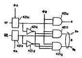
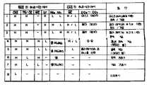
제 3 도는 모드 판별회로(422)의 회로다이어그램이다. 모드 판별회로(422)는 래치 회로(422a 및 422b), 인버터(421c 및 421d) 및 AND게이트(421e, 421f 및 421g)를 포함한다. 래치 회로(421a 및 421b)는 클록발생기(29)로부터 공급된 클록(OCA)에 응하여 특정기능 신호(SF) 및 기입인에이블 신호(WE)를 입력으로 한다. 래치회로(421a 및 421b)의 출력은 AND게이트(421e 및 421f)와 또한 인버터 (421c 및 421d)의 입력에 각각 공급된다. 인버터(421c)의 출력은 AND게이트(421f 및 421g)에 공급된다. 인버터(421d)의 출력은 AND게이트(421g)에 공급된다. 클록 발생기(29)로 부터 공급된 클록 신호(ψB)는 AND게이트(421e, 421f 및 421g)에 공급된다. AND게이트(421e)의 출력은 레지스터 동작모드 세팅신호(R)이다. AND게이트(421f)의 출력은 정상동작모드 세팅신호(BN)이고, AND게이트(421g)의 출력은 블록동작모드 세팅신호(BB)이다. 정상동작모드/블록동작모드 스위칭신호는 신호(BN및 BB)로 구성된다. 모드판별 회로(422)의 입력과 출력사이의 관계는 테이블 1에 도시된다.3 is a circuit diagram of themode determination circuit 422. Themode determination circuit 422 includes latch circuits 422a and 422b, inverters 421c and 421d, and ANDgates 421e, 421f and 421g. Thelatch circuits 421a and 421b input the specific function signal SF and the write enable signal WE in response to the clock OCA supplied from theclock generator 29. The outputs of thelatch circuits 421a and 421b are supplied to the ANDgates 421e and 421f and also to the inputs of the inverters 421c and 421d, respectively. The output of the inverter 421c is supplied to the ANDgates 421f and 421g. The output of the inverter 421d is supplied to the ANDgate 421g. The clock signal ψB supplied from theclock generator 29 is supplied to the ANDgates 421e, 421f and 421g. The output of the ANDgate 421e is a register operation mode setting signal R. The output of the AND gate 421f is the normal operation mode setting signal BN , and the output of the ANDgate 421g is the block operation mode setting signal BB. The normal operation mode / block operation mode switching signal is composed of signals BN and BB. The relationship between the input and output of themode discrimination circuit 422 is shown in Table 1.

[테이블 1][Table 1]

Figure kpo00009
Figure kpo00009

다음에 상세히 기술될것처럼, RAM 장치가 레지스터 동작모드에 세트될 때. 센스증폭기 및 I/O게이트(11)는 데이터 버스(DB1)으로부터 차단된다. 이것은 버스접속/차단제어회로(45)에 의하여 성취된다(이것은 간략화를 위해 제 1 도에서 제외되었다).As described in detail later, when the RAM device is set to register operation mode. The sense amplifier and I / O gate 11 are isolated from the data bus DB1 . This is accomplished by the bus connection / disconnection control circuit 45 (this is omitted in FIG. 1 for simplicity).

제 4 도는 버스접속/차단제어회로(45)의 회로다이어그램이다. 도시된 것처럼, 회로(45)는 인버터(45a) 및 AND게이트(45b)로 구성된다. 인버터의 입력은 레지스터 모든 세팅 신호(R)로 공급되고, 그것의 출력은 AND게이트(45b)에 공급된다. AND게이트(45)는 또한 정상동작모드/블록동작모드 스위칭신호(B)로 공급되고, 정상동작모드/블록동작모드 스위칭신호(B)는 정상동작모드 세팅신호(BN) 및 블록동작모드 세팅신호(BB)가 제 2a 도에 도시된 OR게이트에 의한 OR동작에 종속됨으로서 획득된다(이것은 간략화를 위해 제 1 도에서 제외되었다). RAM장치가 레지스터 동작모드에 세트될때, 열 디코더(7)의 각 열에 공급된 AND게이트의 출력(ψCA)은 "L"에 유지된다. 제 7 도에 도시된 것처럼, 열 디코더(7)는 각 열에 대하여 AND게이트(71a,72a,73a,…)를 포함한다. 그러므로 레지스터 동작모드동안, AND게이트(71a,72a,73a,…)는 접속되고 그것에 의해 센스증폭기 및 I/O게이트(11)는 데이터 버스(DB1)로부터 차단된다. 따라서, 칼라래지스터(39 및 40)와 외부 회로사이에서 기입 동작 및 판독 동작은 성취될 수 있다.4 is a circuit diagram of the bus connection / blocking control circuit 45. As shown in FIG. As shown, the circuit 45 is composed of an inverter 45a and an AND gate 45b. The input of the inverter is supplied to the register all setting signals R, and its output is supplied to the AND gate 45b. The AND gate 45 is also supplied with the normal operation mode / block operation mode switching signal B, and the normal operation mode / block operation mode switching signal B is set to the normal operation mode setting signal BN and the block operation mode setting. The signal BB is obtained by subjecting to an OR operation by the OR gate shown in FIG. 2A (this is omitted in FIG. 1 for simplicity). When the RAM device is set in the register operation mode, the output ψCA of the AND gate supplied to each column of thecolumn decoder 7 is kept at " L ". As shown in FIG. 7, thecolumn decoder 7 includes AND gates 71a, 72a, 73a, ... for each column. Therefore, during the register operation mode, the AND gates 71a, 72a, 73a, ... are connected so that the sense amplifier and the I / O gate 11 are disconnected from the data bus DB1 . Thus, the write operation and the read operation between the color registers 39 and 40 and the external circuit can be achieved.

제 5 도는 제 2 도에 도시된 1/4어드레스 디코더(D1) 의 회로 다이어그램이다. 1/4어드레스 디코더(D1) 는 인버터(51a 및 51b), AND게이트(52a 내지 52f), OR게이트(53a 내지 53d)로 구성된다. 정상동작모드 세팅신호(BN)는 인버터(51a) 및 AND게이트(52a)에 공급되고, 블록동작모드 세팅신호(BB)는 인버터(51b) 및 AND게이트(52b)에 공급된다. 인버터(51a 및 51b)의 출력은 각각 AND게이트(52b 및 52a)에 인가된 다. AND게이트(52a)의 출력은 AND게이트(52c 내지 52f)에 공급되고, AND게이트(52b)의 출력은 OR게이트(53a 내지 53d)에 공급된다. 열 어드레스 신호의 어드레스 비트(A0) 및 그것의 인버트 된 비트

Figure kpo00010
는 AND게이트(52c 및 52d)에 각각 공급되고, 어드레스 비트(A1) 및 그것의 인버트된 비트
Figure kpo00011
는 각각 AND게이트(52e 및 52f)에 공급된다. AND게이트(52c 내지 52f)의 출력은 OR게이트(53a 내지 53d)에 공급된다. RAM장치는 신호(BN)가 "H"에 세트되고 신호(BB)가 "L"에 세트된 정상동작모드에서 세트될 때, AND게이트(52c 내지 52f)의 모든 게이트는 개방되고, 그러므로 어드레스 비트
Figure kpo00012
는 그것을 통하여 통과된다. 이때, AND게이트(52b)의 출력은 "L"에 유지되므로, 앞의 어드레스 비트는 OR게이트(53a 내지 53d)를 통하여 또한 통과된다. 결국, 열은 어드레스 비트의 값에 의존하여 선택될 것이다.FIG. 5 is a circuit diagram of the 1/4 address decoder D1 shown in FIG. The quarter address decoder D1 is composed of inverters 51a and 51b, AND gates 52a to 52f, and OR gates 53a to 53d. The normal operation mode setting signal BN is supplied to the inverter 51a and the AND gate 52a, and the block operation mode setting signal BB is supplied to the inverter 51b and the AND gate 52b. The outputs of inverters 51a and 51b are applied to AND gates 52b and 52a, respectively. The output of the AND gate 52a is supplied to the ANDgates 52c to 52f, and the output of the AND gate 52b is supplied to the OR gates 53a to 53d. Address bits A0 and inverted bits of the column address signal
Figure kpo00010
Are supplied to the ANDgates 52c and 52d, respectively, and the address bits A1 and its inverted bits are
Figure kpo00011
Are supplied to the ANDgates 52e and 52f, respectively. The outputs of the ANDgates 52c to 52f are supplied to the OR gates 53a to 53d. The RAM device is set in the normal operation mode in which the signal BN is set to " H " and the signal BB is set to " L ", so that all gates of the ANDgates 52c to 52f are open, and therefore Address bits
Figure kpo00012
Is passed through it. At this time, since the output of the AND gate 52b is held at " L ", the preceding address bits are also passed through the OR gates 53a to 53d. Eventually, the column will be selected depending on the value of the address bit.

한편, RAM정치는 신호(BN)가 "L"에 세트되고 신호(BB)가 "H"에 세트된 블록동작모드에서 세트될 때, AND게이트(52b)의 출력은 "H"에 세트된다. 그러므로, 모든 출력된 어드레스 비트

Figure kpo00013
는 "H"에 유지되고, 결론적으로 4개의 열이 한번에 선택될 수 있다. 제 5 도에서, 다른 어드레스 비트(A2-AN)(제 1 도의 예제에서 n=7)는 열 어드러스 디코더(7)에 직접적으로 공급된다. 이것은 차후에 상세히 기술될 것이다.On the other hand, when the RAM policing is set in the block operation mode in which the signal BN is set to "L" and the signal BB is set to "H", the output of the AND gate 52b is set to "H". do. Therefore, all output address bits
Figure kpo00013
Is maintained at "H" and consequently four columns can be selected at a time. In FIG. 5, the other address bits A2 -AN (n = 7 in the example of FIG. 1) are supplied directly to thecolumn address decoder 7. This will be described later in detail.

제 6 도는 데이터 버스(DB1)와 열 어드레스 디코더 셀(7)에 나있는 각 열사이의 접속을 도시했다. 도시된 것처럼, 각 열은 8비트 데이터 버스(DB1)와의 2개의 비트에 접속된다.6 shows a connection between the data bus DB1 and each column listed in the columnaddress decoder cell 7. As shown, each column is connected to two bits with an 8-bit data bus DB1 .

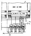
제 7 도는 열 어드레스 디코더(7) 및 센스증폭기 및 I/O게이트(11)의 회로 구성을 도시했다. 도시된것처럼, 열 어드레스 디코더(7)는 각 열들에 대하여 1개의 AND게이트(71a)에 의해 구성되어있다. 센스증폭기 및 I/O게이트(11)는 각 열에 대하여 공급된 2개의 MOS 전송게이트(72a 및 72b) 및 1개의 센스 증폭기(SA)에 의해 구성된다. 제 7 도에서, 기호(MC)는 메모리셀이다.7 shows a circuit configuration of thecolumn address decoder 7 and the sense amplifier and the I / O gate 11. As shown, thecolumn address decoder 7 is constituted by one AND gate 71a for each column. The sense amplifier and I / O gate 11 are constituted by two MOS transfer gates 72a and 72b and one sense amplifier SA supplied for each column. In Fig. 7, the symbol MC is a memory cell.

실시예 동작의 타이밍 챠트인 제 9 내지 12 도뿐만 아니라 동작 진리 테이블을 도시하는 제 8 도를 참조하여 앞에 기술된 구조를 가진 실시예의 동작에 대해 설명된다. 실시예의 동작모드는 주로 레지스터 동작모드, 정상동작모드 및 블록동작모드로 분류될 수 있다. 동작의 설명은 이 다음에 제시된다.The operation of the embodiment having the structure described above is described with reference to FIG. 8 showing the operation truth table as well as the timing chart of the operation of the embodiment. The operation mode of the embodiment may be mainly classified into a register operation mode, a normal operation mode, and a block operation mode. A description of the operation is presented next.

제 9(a) 및 9(e)에 도시된 것처럼, 행 어드레스 스트로우브 신호

Figure kpo00014
가 "L"에 스위치될 때, 행 어드레스는 메모리셀 어레이(1 내지 4)로 들어간다. 이때 제 9(D)도의 전송 인에이블/출력 인에이블 신호
Figure kpo00015
와 특정기능신호(SF)는 각각 "H"와"L"에 유지된다. 이때 제 9(b)도의 열 어드레스 스트로우브 신호
Figure kpo00016
는 "H"에 유지된다. 그때, 제 9(h) 도에 도시된것처럼, 로우-액티브 신호인 기입 인에이블 신호
Figure kpo00017
는 "L"에 유지된다. 그러므로, 모드 판별회로(422)는 "H"에 세트된 레지스터 동작모드 세팅신호(R)를 출력한다. 이때, 정상동작모드 세팅신호(BN) 및 블록동작모드 세팅신호(BB)는 "L"에 유지된다. 레지스터 동작모드 세팅신호(R)가 "H"에 세트되기 때문에 레지스터 디코더(421)는 인에이블이 된다.Row address strobe signal, as shown in ninth (a) and ninth (e)
Figure kpo00014
Is switched to " L ", the row address enters the memory cell arrays 1-4. At this time, the transmit enable / output enable signal of FIG. 9 (D)
Figure kpo00015
And the specific function signal SF are held at " H " and " L ", respectively. At this time, the column address strobe signal of FIG. 9 (b)
Figure kpo00016
Is kept at "H". Then, as shown in Fig. 9 (h), the write enable signal which is a low-active signal
Figure kpo00017
Is kept at "L". Therefore, themode determining circuit 422 outputs the register operation mode setting signal R set at " H ". At this time, the normal operation mode setting signal BN and the block operation mode setting signal BB are held at " L ". The register decoder 421 is enabled because the register operation mode setting signal R is set to " H ".

한편, 센스 증폭기 및 I/O게이트(11)는 데이터 버스(DB1)로부터 차단되고 따라서, 메모리셀 어레이(1)는 그것으로부터 차단된다. 이것은 레지스터 동작모드 세팅신호(R)가 "H"에 세트되기 때문이며 따라서 제 4 도에 도시된 AND게이트(45b)는 "L"에 세트된 제어신호(ψCA)를 발생한다. 기입 인에이블 신호(WE)가 "L"에 유지되기 때문에, 내부제어신호(W)는 "H"에 유지되고 따라서 타이밍 조정회로(TA3)는 동작된다. 결국, 레지스터 동작모드 세팅신호(R)는 타이밍 조정회로(TA3)를 경유하여 기입 증폭기352, 362,372 및 382)에 인가되도록 한다. 그것에 의하여, 기입 증폭기(352, 362, 372 및 382)는 인에이블된다. 한편 기입 인에이블 신호

Figure kpo00018
가 "L"에 세트될 때, 로우-액티브 신호인 내부 제어신호(W)는 "L"에 세트된다. 그것에 의하여, 레지스터 동작모드 세팅신호(R)는 타이밍 조정회로(TA2)에 의하여 전송되는것이 방지되고, 모든 센스증폭기(351, 361, 371 및 381)는 동작 불능이 된다. 타이밍 조정회로(TA2및 TA3)는 메모리셀 어레이(1)가 데이터 버스(DB1)으로부터 완전히 차단된 후 인에이블 상태에 있는 센스 증폭기 및 기입증폭기(351, 361, 371 및 381) 및 기입증폭기(352, 362, 372 및 382)를 세트하기 위하여 제공된다.On the other hand, the sense amplifier and I / O gate 11 are cut off from the data bus DB1 and therefore thememory cell array 1 is cut off from it. This is because the register operation mode setting signal R is set to " H " and thus the AND gate 45b shown in FIG. 4 generates the control signal ψCA set to " L ". Since the write enable signal WE is held at " L ", the internal control signal W is held at " H " and therefore the timing adjustment circuit TA3 is operated. As a result, the register operation mode setting signal R is applied to the write amplifiers 352, 362, 372 and 382 via the timing adjustment circuit TA3 . Thereby, the write amplifiers 352, 362, 372 and 382 are enabled. Write enable signal
Figure kpo00018
Is set to " L ", the internal control signal W, which is a low-active signal, is set to " L ". Thereby, the register operation mode setting signal R is prevented from being transmitted by the timing adjustment circuit TA2 , and all thesense amplifiers 351, 361, 371 and 381 are disabled. The timing adjustment circuits TA2 and TA3 are configured to sense amplifiers and writeamplifiers 351, 361, 371 and 381 which are in an enabled state after thememory cell array 1 is completely disconnected from the data bus DB1 . To set amplifiers 352, 362, 372 and 382.

선택기(31 내지 34)는 각각 선택기(S1내지 S4)의 출력을 선택한다. 왜냐하면, 선택기들은 "H"에 세트되어있는 딜레이된 레지스터 동작모드 세팅신호(R)로 공급되기 때문이다. 이때, 선택기(S1내지 S4)는 각각 데이터(DQ0내지 DQ3)를 선택한다. 왜냐하면, 선택기들은 "H"에 세트되어있는 딜레이된 레지스터 동작모드 세팅신호(R)로 공급되기 때문이다.Theselectors 31 to 34 select the outputs of the selectors S1 to S4 , respectively. This is because the selectors are supplied with the delayed register operation mode setting signal R set at " H ". At this time, the selectors S1 to S4 select data DQ0 to DQ3 , respectively. This is because the selectors are supplied with the delayed register operation mode setting signal R set at " H ".

제 9(h) 도의 기입 인에이블 신호

Figure kpo00019
가 "L"에 스위치되기전에, 제 9a 도에 도시된 것처럼 행 어드레스 스트로우브 신호(RAS)의 하강과 동기하여 행 어드레스 디코더(6)로부터 공급된 행 어드레스 메모리셀 어레이(1)내로 들어간다. 이때 행 어드레스 신호외의 2개 어드레스 비트(RA0내지 R1)는 레지스터(39, 40 및 41)중의 어떤 한 개를 선택하기 위하여 사용된다.Write enable signal of FIG. 9 (h)
Figure kpo00019
Before is switched to " L ", it enters into the row addressmemory cell array 1 supplied from therow address decoder 6 in synchronization with the falling of the row address strobe signal RAS as shown in FIG. 9A. At this time, two address bits RA0 to R1 other than the row address signal are used to select any one of theregisters 39, 40, and 41.

예를들면 어드레르 비트(RA0)가 "L"에 세트되고 어드레스 비트(RA1)가 "L"에 세트될때 레지스터 실내신호(a3)는 "H"에 세트되고 그것에 의하여 전송게이트(T3)는 온으로 된다. 결국, 마스크 레지스터(41)는 데이터 버스(DB1) 및 전송 게이트(T3)를 경유하여 마스크 레지스터(41)의 최하위 디지트 비트(M0)로 기입된다. 마찬가지로, 데이타(DQ1내지 DQ3)는 마스크 레지스터(41)의 영역(M1내지 M3)으로 기입된다.For example, when the address bit RA0 is set to "L" and the address bit RA1 is set to "L", the register indoor signal a3 is set to "H" and thereby the transfer gate T3. ) Is turned on. As a result, themask register 41 is written to the least significant digit bit M0 of themask register 41 via the data bus DB1 and the transfer gate T3 . Similarly, the data DQ1 to DQ3 are written into the areas M1 to M3 of themask register 41.

제 9(a) 내지 9(e) 에 도시된 것처럼, 메모리 제어회로로부터 공급된 행어드레스 스트로우브 신호

Figure kpo00020
의 하강 시간에, 특정기능신호(SF)는 "H"에 세트된다. 이때, 제 9(b) 도의 열 어드레스 스트로우브 신호
Figure kpo00021
및 제 9(d) 도의 전송 인에이블/출력 인에이블 신호
Figure kpo00022
는 "H"에 유지된다. 제 9(h) 도에 도시된 것처럼, 그때, 기입 인에이블 신호
Figure kpo00023
는 "H"에 유지된다.As shown in the ninth (a) to ninth (e), the row address strobe signal supplied from the memory control circuit.
Figure kpo00020
At the fall time of, the specific function signal SF is set to " H ". At this time, the column address strobe signal of FIG. 9 (b)
Figure kpo00021
And the transmission enable / output enable signal of FIG. 9 (d).
Figure kpo00022
Is kept at "H". As shown in Fig. 9 (h), the write enable signal is then applied.
Figure kpo00023
Is kept at "H".

그로므로 모드 판별회로(422)는 앞에 기술한 기입 동작의 경우에처럼 "H"에 세트되어있는 레지스터 동작모드 세팅신호(R)를 출력한다. 이때 정상동작모드 세팅신호(BN) 및 블록동작모드 세팅신호(BB)는 "L"에 유지된다.Therefore, themode determining circuit 422 outputs the register operation mode setting signal R set at " H " as in the case of the write operation described above. At this time, the normal operation mode setting signal BN and the block operation mode setting signal BB are maintained at " L ".

레지스터 동작모드 세팅신호(R)가 "H"에 세트되었기 때문에, 레지스터 디코더(421)는 동작된다. 한편 센스 증폭기 및 I/O게이트(11)는 데이터 버스(DB1)로부터 차단되고 따라서 메모리셀 어레이(1)는 차단된다. 이것을 레지스터 동작모드 세팅신호(R)가 "H"에세트되기 때문이며, 따라서 제 4 도에 도시된 AND게이트(45b)는 "L"에 세트된 제어신호(ψCA)를 발생한다. 기입 인에이블 신호

Figure kpo00024
는 "H"에 유지되고 그것에 의하여 내부제어신호(W)는 "L"에 유지된다 그러므로 타이밍 조정회로(TA3)는 동작불능이며, 따라서 기입 증폭기(352, 362, 372 및 382)는 또한 동작불능이 된다. 한편, 로우-액티브 내부 제어신호
Figure kpo00025
는 인에이블신호(WE)가 "H"에 세트될때, "H"에 세트된다. 그것에 의하여, 레지스터 동작모드 세팅신호(R)는 타이밍 조정회로(TA2)를 통과된다. 결론적으로, 모든 센스증폭기(351, 361, 371 및 381)는 동작된다.Since the register operation mode setting signal R is set to " H ", the register decoder 421 is operated. Meanwhile, the sense amplifier and the I / O gate 11 are cut off from the data bus DB1 and thus thememory cell array 1 is cut off. This is because the register operation mode setting signal R is set to " H ", so the AND gate 45b shown in FIG. 4 generates the control signal ψCA set to " L ". Write Enable Signal
Figure kpo00024
Is held at " H " and thereby the internal control signal W is held at " L ". Therefore, the timing adjusting circuit TA3 is inoperable, so that the write amplifiers 352, 362, 372 and 382 are also operated. It becomes impossible. Meanwhile, low-active internal control signal
Figure kpo00025
Is set to "H" when the enable signal WE is set to "H". As a result, the register operation mode setting signal R passes through the timing adjustment circuit TA2 . In conclusion, allsense amplifiers 351, 361, 371 and 381 are operated.

제 6 도에 도시된 것 처럼, 선택기(S5)는 1/4어드레스 디코더(D1)의 출력에 응하여 데이터 버스(DB1)의 최상의 순서 데이터 라인에 위치한 오직 데이터 라인(DB1a)을 선택한다. 그것에 의하여 센스 버퍼(351)는 선상위 순서 데이터 라인에 위치한 오직 데이터 라인을 선택한다. 그것에 의하여 센스 버퍼(351)는 선택기(S5)를 통하여 비트라인(DB1a)에 접속된다. 이 방법에서, 마스크 레지스터(41)의 영역(MO)에 기억된 데이터는 선택기(S5)를 통하여 센스버퍼(351)에 인가된다. 그리고 마스크 레지스터(41)의 영역(M1내지 M3)에 기억된 데이타는 각각 센스 버퍼(361, 371 및 381)에 인가된다, 결국, 마스크 레지스터(41)에 기억된 데이터는 데이터(DQ0및 DQ3)로서 외부회로에 전송될 수 있다.As shown in FIG. 6, the selector S5 selects only the data line DB1a located at the highest order data line of the data bus DB1 in response to the output of the quarter address decoder D1 . do. Thereby thesense buffer 351 selects only the data lines located in the top-order data lines. Thereby thesense buffer 351 is connected to the bit line DB1a via the selector S5 . In this way, the data stored in the area(O M) of themask register 41 is applied to thesense buffer 351 through the selector (S5). The data stored in the areas M1 to M3 of the mask register 41 are applied to the sense buffers 361, 371, and 381, respectively. Consequently, the data stored in themask register 41 is stored in the data DQ0. And DQ3 ) to an external circuit.

칼라 레지스터(39 또는 40)에 관한 레지스터 동작모드는 마스크 레지스터에 관한 동작과 같다.The register operation mode for thecolor register 39 or 40 is the same as the operation for the mask register.

행 어드레스 스트로우브 신호

Figure kpo00026
가 제 10(a) 도에 도시된 것처럼 "L"에 유지된다. 이때 제 10(b) 도의 열 어드레스 스트로우브 신호
Figure kpo00027
및 제 10(d) 도의 전송 인에이블/출력 인에이블 신호
Figure kpo00028
는 "H"에 유지된다. 정상동작모드의 기입 동작에서, 기입 인에이블 신호(WE)는 "L"로 스위치된다. 그러므로, 모드판별회로(422)는 "L"에 세트되어있는 레지스터 동작모드 세팅신호(R)를 발생한다. 그것에 의하여, 레지스터 디코더(421)는 동작불능이 되며 모든 레지스터 선택신호 (a1내지 a3)는 "L"에 세트된다. 따라서 모든 전송게이트(T1내지 T3)는 오프되고 칼라 레지스터(39 및 40) 및 마스크 레지스터(41)는 데이터 버스(DB1)로부터 차단된다. 한편, 제 2a 도에 도시된 OR게이트(44)에 의해 동작된 OR동작의 결과인 정상동작모드/블록동작모드 스위칭신호(B)는 "H"에 유지되고 레지스터 동작모드 세팅신호(R)는 "L"에 유지된다. 결국, 제 4 도에 도시된 AND게이트는 "H"에 유지되고 레지스터 동작모드 세팅신호(R)는 "L"에 유지된다. 결국 제 4 도에 도시된 AND게이트는 "H"에서 출력(ψCA)을 세하며 따라서 열 디코더(7)는 동작불능이 된다. 그러므로, 메모리셀 어레이(1)는 데이터 버스(DB1)에 접속된다. 마찬가지로, 열 디코더(8, 9 및 10)는 제 4 도에 도시된 AND게이트(45b)로부터 유래된 "H"에 제어신호(ψCA)를 세트시킴으로서 인에이블된다. 그러므로 그들은 데이터 버스(DB2, DB3및DB4)에 접속된다.Row address strobe signal
Figure kpo00026
Is maintained at " L " as shown in Fig. 10 (a). At this time, the column address strobe signal of FIG. 10 (b)
Figure kpo00027
And the transmission enable / output enable signal of FIG. 10 (d).
Figure kpo00028
Is kept at "H". In the write operation in the normal operation mode, the write enable signal WE is switched to " L ". Therefore, themode discrimination circuit 422 generates the register operation mode setting signal R set at " L ". Thereby, the register decoder 421 becomes inoperative and all the register selection signals a1 to a3 are set to " L ". Thus all the transfer gates T1 to T3 are off and the color registers 39 and 40 and themask register 41 are disconnected from the data bus DB1 . On the other hand, the normal operation mode / block operation mode switching signal B which is a result of the OR operation operated by the OR gate 44 shown in Fig. 2A is kept at " H " and the register operation mode setting signal R is Is kept at "L". As a result, the AND gate shown in FIG. 4 is held at " H " and the register operation mode setting signal R is held at " L ". As a result, the AND gate shown in FIG. 4 counts the output ψCA at " H " so that thecolumn decoder 7 becomes inoperable. Therefore, the memory cell array1 is connected to the data bus DB1 . Similarly, thecolumn decoders 8, 9 and 10 are enabled by setting the control signal ψCA at " H " derived from the AND gate 45b shown in FIG. Therefore they are connected to the data buses DB2 , DB3 and DB4 .

제 10(h) 도의 기입 인에이블 신호

Figure kpo00029
가 "L"로 스위치될때, 내부 제어신호
Figure kpo00030
는 각각 "H" 및 "L"에 세트된다. 그러므로 타이밍 조정회로(TA2및 TA3)는 각각 동작불능 및 인에이블되고 그것에 의하여 센스버퍼(351, 361, 371 및 381)는 동작불능이며 한편 기입증폭기(352, 362, 372 및 382)는 인에이블된다. 이때, 선택기(S1)는 데이타(DQ0)의 출력을 선택하고 선택기(31)는 선택기(S1)의 출력을 선택한다. 그때, 제 10(b) 도의 열 어드레스 스트로우브 신호
Figure kpo00031
의 하강에 응하여, 열 어드레스는 메모리셀 어레이(1 내지 4)에 공급된다. 그때 데이타(DQ0)는 선택기(S1내지 S4), 선택기(31 내지 34), 기입증폭기(352, 362, 372 및 382), 데이터 버스(DB1) 및 열 디코더(7)을 차례로 경유하여 4비트 단위당 메모리셀 어레이(1)로 기입된다. 마찬가지로, 데이타(DQ2내지 DQ4)는 4비트단위당 메모리셀 어레이(2 내지 4)로 기입된다.Write enable signal of FIG. 10 (h)
Figure kpo00029
Is switched to "L", the internal control signal
Figure kpo00030
Are set to "H" and "L", respectively. Therefore, the timing adjustment circuits TA2 and TA3 are disabled and enabled, respectively, whereby the sense buffers 351, 361, 371 and 381 are disabled and the write amplifiers 352, 362, 372 and 382 are disabled. Is enabled. At this time, the selector S1 selects the output of the data DQ0 and theselector 31 selects the output of the selector S1 . At that time, the column address strobe signal of FIG. 10 (b)
Figure kpo00031
In response to the falling of the column addresses, the column addresses are supplied to thememory cell arrays 1 to 4. The data DQ0 then passes through the selectors S1 to S4 , theselectors 31 to 34, the write amplifiers 352, 362, 372 and 382, the data bus DB1 and thecolumn decoder 7 in turn. Thememory cell array 1 is written to thememory cell array 1 per 4-bit unit. Similarly, data DQ2 to DQ4 are written intomemory cell arrays 2 to 4 per 4-bit unit.

행 어드레스 스트로우브 신호

Figure kpo00032
가 제 10(a) 도에 도시된 것처럼 "L"에 스위치될때 행어드레스는 메모리셀 어레이(1 내지 4)에 공급된다. 이때, 특정 기능신호(SF)는 제 10(e) 도에 도시된 것처럼 "L"에 유지된다. 이때 제 10(b) 도의 열 어드레스 스트로우브 신호
Figure kpo00033
및 제 10(d) 도의 전송 인에이블/출력 인에이블 신호
Figure kpo00034
는 "H"에 유지된다. 정상동작모드의 판독 동작에서, 기입 인에이블 신호
Figure kpo00035
는 "H"로 스위치된다. 이때, 모드판별회로(422)는 전에 기술된 정상동작모드의 기입동작의 경우에서처럼 "L"에 세트되어 있는 레지스터 동작모드 세팅신호(R)를 발생한다. 따라서 모든 전송 게이트(T1내지 T3)는 오프되고, 칼라 레지스터(39 및 40) 및 마스크 레지스터(41)는 정상동작모드의 기입동작의 경우처럼 데이터 버스(DB1)로부터 차단된다. 한편, 제 2a 도에 도시된 OR게이트(44)에 의해 동작된 OR동작의 결과인 정상동작모드/블록동작모드 스위칭신호(B)는 "H"에 유지되고 한편 레지스터 동작모드 세팅신호(R)는 "L"에 유지된다.Row address strobe signal
Figure kpo00032
When is switched to " L " as shown in Fig. 10A, the row address is supplied to the memory cell arrays 1-4. At this time, the specific function signal SF is held at " L " as shown in FIG. At this time, the column address strobe signal of FIG. 10 (b)
Figure kpo00033
And the transmission enable / output enable signal of FIG. 10 (d).
Figure kpo00034
Is kept at "H". In the read operation in the normal operation mode, the write enable signal
Figure kpo00035
Is switched to "H". At this time, themode discrimination circuit 422 generates the register operation mode setting signal R set at " L " as in the case of the write operation of the normal operation mode described previously. Therefore, all the transfer gates T1 to T3 are turned off, and the color registers 39 and 40 and themask register 41 are disconnected from the data bus DB1 as in the case of the write operation in the normal operation mode. On the other hand, the normal operation mode / block operation mode switching signal B which is a result of the OR operation operated by the OR gate 44 shown in Fig. 2A is held at " H " and the register operation mode setting signal R Is kept at "L".

결국 제 4 도에 도시된 AND게이트(45b)는 "H"에서 출력(ψCA)을 세트하며 따라서 열 디코더(7)는 인에이블된다. 그러므로, 메모리셀 어레이(1)는 데이터 버스(DB1)에 접속된다. 마찬가지로, 열 디코더(8, 9 및 10)는 제 4 도에 도시된 AND게이트로부터 유래된 "H"에 제어신호(ψCA)를 세트시킴으로서 인에이블된다. 따라서 그들은 데이터 버스(DB2, DB3및 DB4)에 접속된다. 기입 인에이블 신호

Figure kpo00036
는 제 10(f) 도에 도시된 것처럼 "H"에 유지되기 때문에 내부제어 신호
Figure kpo00037
는 각각 "L" 및 "H"에 세트된다. 그러므로 타이밍 조정회로(TA2및 TA3)는 각각 인에이블 및 동작불능이 되며, 그것에 의하여 센스 버퍼(351, 361, 371 및 381)는 인에이블되고 기입 증폭기(352, 362, 372 및 382)는 동작 불능이 된다. 이때, 4비트 단위당 데이터 버스(DB1)에서 출력되는 데이타는 어드레스 비트
Figure kpo00038
로 구성된 열 어드레스 (CA0)의 값 및 어드레스 비트
Figure kpo00039
로 구성된 CA1의 값에 의존하는 선택기(S5)에 의하여 선택된다. 선택된 데이터는 센스버퍼(351)를 경유하여 DQ0로서 출력된다. 마찬가지로, 선택된 데이터는 각각 데이터(DQ1내지 DQ3)로서 메모리셀 어레이(2 내지 4)로부터 판독된다.As a result, the AND gate 45b shown in FIG. 4 sets the output ψCA at " H " so that thecolumn decoder 7 is enabled. Therefore, the memory cell array1 is connected to the data bus DB1 . Similarly, thecolumn decoders 8, 9 and 10 are enabled by setting the control signal ψCA at " H " derived from the AND gate shown in FIG. Thus they are connected to the data buses DB2 , DB3 and DB4 . Write Enable Signal
Figure kpo00036
The internal control signal is maintained at " H " as shown in Fig. 10 (f).
Figure kpo00037
Are set to "L" and "H", respectively. The timing adjustment circuits TA2 and TA3 are therefore enabled and disabled respectively, whereby the sense buffers 351, 361, 371 and 381 are enabled and the write amplifiers 352, 362, 372 and 382 are It becomes inoperable. At this time, the data output from the data bus DB1 per 4-bit unit is an address bit.
Figure kpo00038
And address bits of column address (CA0 ) consisting of
Figure kpo00039
Is selected by the selector S5 depending on the value of CA1 . The selected data is output as DQ0 via thesense buffer 351. Similarly, the selected data is read out from thememory cell arrays 2 to 4 as data DQ1 to DQ3 , respectively.

이 동작모드에서, 4개의 상호 인접한 열은 동시에 선택될 수 있다. 이것은 종래의 다이나믹 랜덤 억세스 메모리의 니블 비트와 일치한다. 다음 설명에서, 셀에 기입된 데이타는 칼라 레지스터(39 또는 40)에 기억된 내용이라 가정한다. 그러므로 칼라 레지스터(39 또는 40)에 기억된 데이터는 임의의 4개의 칼라 레지스터에 일치하는 단위블록당 메모리셀에 동시에 기입될 수 있다. 예를들면, 칼라 레지스터가 4비트로 구성된 경우에, 데이타는 16비트단위당 메모리셀에 기입될 수 있다. 칼라 레지스터(39 및 40)중의 하나는 입력 데이터(DQ0내지 DQ3)의 레벨 상태에 의존하여 선택된다. 예를들면, 데이터(DQ3)가 "L"에 세트된 경우에, 칼라 레지스터(40)의 내용은 열 어드레스 신호에 의해 선택된 4개의 셀 블록의 제 1 열(4열당 4비트에 일치하는)의 메모리셀에 기입된 데이타이다. 한편 DQ0는 "H"에 세트되는 경우에 칼라 레지스터(39)에 기억된 데이타는 4개의 메모리셀 블록의 제 1 열의 메모리셀에 기입된 데이타이다. 데이타(DQ1)가 "H"에 유지된 경우에, 칼라 레지스터(39)의 내용은 선택된 셀블록의 제 2 열의 메모리셀에 기입된 데이타이다. 대신에, 데이타(DQ1)가 "L"에 유지된 경우에, 칼라 레지스터(40)의 내용은 선택된 메모리셀 블록의 제 2 열의 메모리셀에 기입된 데이터이다. 마찬가지로, 데이타(DQ2)는 칼라 레지스터(39 및 40)중의 하나가 메모리셀 블록의 제 3 열의 메모리셀에 기입되도록 선택되어야한다는 명령의 데이터로서 사용된다. 그리고 데이타(DQ3)는 칼라 레지스터(39 및 40)중의 하나가 메모리셀 블록의 제 4 열의 메모리셀에 기입되도록 선택되어야한다는 명령의 데이타로서 사용된다. 예를들면, 모든 데이타(DQ1내지 DQ3)가 "L"에 세트될때 칼라 레지스터(40)에 기억된 내용은 하나의 메모리셀 어레이의 4열 전부의 메모리셀에 기입된다.In this mode of operation, four mutually adjacent columns can be selected at the same time. This is consistent with the nibble bits of a conventional dynamic random access memory. In the following description, it is assumed that the data written in the cell is the content stored in thecolor register 39 or 40. Therefore, the data stored in thecolor register 39 or 40 can be simultaneously written to the memory cells per unit block corresponding to any four color registers. For example, if the color register consists of 4 bits, data can be written to memory cells per 16 bit unit. One of the color registers 39 and 40 is selected depending on the level status of the input data DQ0 to DQ3 . For example, if data DQ3 is set to "L", the contents ofcolor register 40 are the first column (corresponding to 4 bits per four columns) of the four cell blocks selected by the column address signal. Data written to the memory cell. On the other hand, when DQ0 is set to " H ", the data stored in thecolor register 39 are data written in the memory cells of the first column of the four memory cell blocks. In the case where the data DQ1 is held at " H ", the contents of thecolor register 39 are data written in the memory cells of the second column of the selected cell block. Instead, when the data DQ1 is held at " L ", the contents of thecolor register 40 are data written to the memory cells of the second column of the selected memory cell block. Similarly, data DQ2 is used as data of an instruction that one of the color registers 39 and 40 should be selected to be written to the memory cells of the third column of the memory cell block. And data DQ3 is used as data of an instruction that one of the color registers 39 and 40 should be selected to be written to the memory cells of the fourth column of the memory cell block. For example, when all data DQ1 to DQ3 are set to " L ", the contents stored in thecolor register 40 are written to all four rows of memory cells in one memory cell array.

블록동작모드는 제 11(a) 내지 11(g) 도를 참조로 또한 기술된다. 도시된 것처럼, 행 어드레스 스트로우브신호

Figure kpo00040
가 하강할때, 열 어드레스 스트로우브 신호
Figure kpo00041
및 전송 인에이블 신호
Figure kpo00042
는 "H"에 유지된다. 그리고, 이때 특정기능신호(SF) 및 기입 인에이블 신호
Figure kpo00043
는 "L"에 유지된다. 그때 행 어드레스는 메모리셀 어레이(1 내지 4)에 들어간다. 그다음, 열 어드레스 스트로우브 신호
Figure kpo00044
가 하강하고 기입 인에이블 신호
Figure kpo00045
가 "L"에 유지될 때, 이 데이타는 메모리셀 어레이(1 내지 4)의 열에 기입된다. 블록동작모드에서 데이터는 4비트단위당 메모리셀에 기입된다. 그러므로 제 5 도를 참조하여 전에 기술한것처럼, 4개의 열 어드레스 비트
Figure kpo00046
는 1에 세트되고 단위블록당 선택된 열 어드레스는 열 어드레스비트
Figure kpo00047
에 부가된 다른 열 비트에 의해 결정된다.The block operation mode is also described with reference to FIGS. 11 (a) to 11 (g). As shown, row address strobe signal
Figure kpo00040
Column strobe signal when
Figure kpo00041
And transmit enable signals
Figure kpo00042
Is kept at "H". In this case, the specific function signal SF and the write enable signal are
Figure kpo00043
Is kept at "L". The row address then enters the memory cell arrays 1-4. Then, the column address strobe signal
Figure kpo00044
Falls and Write Enable Signal
Figure kpo00045
Is held at " L ", this data is written to the columns of the memory cell arrays 1-4. In the block operation mode, data is written to memory cells per 4-bit unit. Therefore, as previously described with reference to Figure 5, four column address bits
Figure kpo00046
Is set to 1 and the selected column address per unit block is the column address bit.
Figure kpo00047
Determined by the other column bits added to it.

이것은 12(a) 내지 12(g)도에 참조로 기술된다. 열 어드레스 스트로우브 신호

Figure kpo00048
및 기입 인에이블 신호
Figure kpo00049
가 행 어드레스 스트로우브 신호
Figure kpo00050
의 하강시간에 "L"에 세트될 때 각 메모리셀 어레이(1 내지 4)의 하나의 행에 관한 데이타는 고속으로 하나의 행단위당 데이타 레지스터(15 내지 18)에 전송될 수 있다. 한편 열 어드레스 스트로우브신호
Figure kpo00051
및 기입 인에이블 신호
Figure kpo00052
가 행 어드레스 스트로우브 신호
Figure kpo00053
의 하강시간에 "H" 및 "L"에 세트될 때 데이타는 고속으로 각 메모리셀 어레이(1 내지 4)의 하나의 행에 관하여 메모리셀에 전송될 수 있다.This is described by reference in Figs. 12 (a) to 12 (g). Column address strobe signal
Figure kpo00048
And write enable signals
Figure kpo00049
Row address strobe signal
Figure kpo00050
When set to " L " at the fall time of, data relating to one row of eachmemory cell array 1 to 4 can be transferred to data registers 15 to 18 per one row unit at high speed. Column address strobe signal
Figure kpo00051
And write enable signals
Figure kpo00052
Row address strobe signal
Figure kpo00053
When set to " H " and " L " at the fall time of < Desc /Clms Page number 5 >

앞에 기술된것처럼, 본 발명에 따라, 레지스터와 같이 내장 레지스터의 내용은 임의로 판독 및 외부회로에 전송될 수 있고, 또한 외부회로로부터 공급된 데이타는 내장 레지스터에 기입될 수 있다. 그러므로, 항상, 내장, 레지스터의 내용을 직접 알수 있다.As described above, according to the present invention, the contents of an internal register, such as a register, can be arbitrarily read and transferred to an external circuit, and data supplied from the external circuit can also be written to an internal register. Therefore, you can always know the contents of built-in registers directly.

이것은 RAM 장치의 동작 유효시험의 향상된 결과이다. 덧붙여, 예를 들면 잘못된 동작이 내장 레지스터에 관한 잘못에 의한것인지 아닌지를 확인하는 것처럼, RAM장치의 잘못된 동작의 원인을 쉽게 확인할 수 있다. 본 발명은 실시예에 제한되지 않으며 변화와 수정은 본 발명의 범위를 벗어나지 않고 가능할 것이다.This is an improved result of the operational validation of the RAM device. In addition, it is easy to identify the cause of the wrong operation of the RAM device, for example, by checking whether the wrong operation is caused by a built-in register error. The invention is not limited to the embodiments and changes and modifications will be possible without departing from the scope of the invention.

Claims (17)

Translated fromKorean
메모리셀을 갖는 메모리셀 어레이 : 데이터 버스 : 메모리셀 어레이와 대응 데이터 버스사이에 구비된 입/출력 수단 : 소정의 데이터를 기억하는 레지스터 수단 : 데이터 버스와 레지스터 수단사이에 접속된 전송 게이트 수단 : 데이터 버스상의 데이터를 외부회로에 전송하는 제 1 데이타 버퍼 수단 : 외부 회로로부터 공급된 데이터를 데이터 버스에 전송하는 제 2 데이타 버스 수단 : 입/출력 수단을 데이터 버스를 차단하고 제 1 동작모드에서 전송게이트 수단을 오프시키며, 입/출력 수단을 데이타 버스에 에 접속하고 제 2 동작모드에서 전송게이트 수단을 온시키는 제어수단으로 구성되는 레지스터를 구비하며, 제 1 동작모드에서 데이터 판독 혹은 기입 동작이 데이터 버스 및 제 1 및 제 2 버퍼 수단의 어느 하나를 경유하여 메모리셀 어레이와 외부회로간에 수행되며, 제 2 동작모드에서는 데이터 판독 혹은 기입동작이 전송 게이트 수단, 데이터 버스 및 제 1 및 제 2 버퍼 수단의 어느 하나는 경유하여 레지스터 수단과 외부회로가 수행되는 것을 특징으로 하는 반도체 메모리 장치.Memory cell array having memory cells: Data bus: Input / output means provided between memory cell array and corresponding data bus: Register means for storing predetermined data: Transfer gate means connected between data bus and register means: Data A first data buffer means for transferring data on a bus to an external circuit; a second data bus means for transferring data supplied from an external circuit to a data bus; And a register comprising control means for turning off the means, connecting the input / output means to the data bus and turning on the transfer gate means in the second mode of operation, wherein a data read or write operation is performed in the first mode of operation. And external to the memory cell array via one of the first and second buffer means. And a data read or write operation is performed in the second operation mode, wherein the register means and the external circuit are performed via any one of the transfer gate means, the data bus, and the first and second buffer means. .제 1 항에 있어서, 레지스터 수단은 메모리셀 어레이어 기입될 칼라 데이터를 기억하는 레지스터로 구성되는 것을 특징으로 하는 반도체 메모리 장치.2. The semiconductor memory device according to claim 1, wherein the register means comprises a register for storing color data to be written into the memory cell array.제 1 항에 있어서, 레지스터 수단은 메모리셀 어레이에 기입될 칼라 데이터를 기억하는 레지스터로 구성되는 것을 특징으로 하는 반도체 메모리 장치.2. The semiconductor memory device according to claim 1, wherein the register means comprises registers for storing color data to be written in the memory cell array.제 1 항에 있어서, 레지스터 수단은 다수위 레지스터로 구성되며 전송게이트 수단은 다수의 레지스터 각각에 제공되며, 다수의 레지스터의 어느 하나는 메모리셀 어레이어 공급될 어드레스의 일부분에 응하여 대응 전송 게이트 수단을 온 시켜서 데이터 버스에 접속되는 것을 특징으로 하는 반도체 메모리 장치.2. A register according to claim 1, wherein the register means comprises a plurality of registers and the transfer gate means are provided in each of the plurality of registers, one of the plurality of registers corresponding to the corresponding transfer gate means in response to a portion of the address to be supplied to the memory cell array. And turned on and connected to the data bus.제 1 항에 있어서, 레지스터 수단은 외부회로로부터 공급된 소정신호에 응하며 제 1 동작모드의 세팅을 명령하는 제 1 동작모드 세팅신호 및 제 2 동작모드의 세팅을 명령하는 제 2 동작모드 세팅신호를 발생하기 위한 모드 판별수단, 메모리셀 어레이에 공급될 어드레스의 일부분에 응하여 전송 게이트수단의 온/오프를 제어하는 사용되는 제어신호를 발생하기위한 레지스터 디코더 수단, 및 모드 판별 수단에 의해 발생된 제 2 동작모드 세팅신호 및 제 1 동작모드 세팅신호에 응하여 입/출력 수단과 데이터 버스간의 접속 및 차단을 제어하기 위한 수단으로 구성되는 것을 특징으로 하는 반도체 메모리 장치.2. The first operating mode setting signal according to claim 1, wherein the register means responds to a predetermined signal supplied from an external circuit, and the second operating mode setting signal instructs the setting of the first operating mode and the second operating mode setting signal instructing the setting of the second operating mode. A mode decoder for generating a control signal, a register decoder means for generating a control signal used for controlling on / off of the transfer gate means in response to a portion of an address to be supplied to the memory cell array, and And means for controlling connection and disconnection between the input / output means and the data bus in response to the operation mode setting signal and the first operation mode setting signal.제 5 항에 있어서, 접속 및 차단을 제어하기 위한 수단은 제 1 동작모드 및 제 2 동작모드의 어느것이 선택되는가에 따라 다른 제어신호를 발생하며, 입/출력 수단은 데이터 버스에 접속되어 메모리셀 어레이어에 관하여 어드레스 디코터의 기능을 하는 AND게이트로 구성되며, 접속 및 차단을 제어하기 위한 수단은 제어신호를 발생하여 제 2 동작모드가 선택될 때 AND게이트를 동작 불능하게 하며, 접속 및 차단을 제어하기 위한 수단은 제어신호를 발생하여 제 1 동작모드가 선택될 때 AND게이트를 동작가능 하는 것을 특징으로 하는반도체 메모리 장치.6. The apparatus of claim 5, wherein the means for controlling connection and disconnection generates different control signals depending on which of the first and second operating modes is selected, and the input / output means is connected to a data bus to And an AND gate functioning as an address decoder with respect to the arrayer, and means for controlling connection and disconnection generate a control signal to disable the AND gate when the second operation mode is selected, and to connect and disconnect. Means for controlling the semiconductor memory device, characterized in that to generate a control signal to operate the AND gate when the first operation mode is selected.제 1 항에 있어서, 레지스터 수단은 다수의 비트로 구성된 데이터를 기억하며, 제 2 데이타 버퍼 수단은 선택된 동작모드에 따라서 외부회로로부터 공급된 데이터 및 레지스터 수단으로부터 공급된 데이터중의 하나를 선택하기 위한 다수의 선택기, 및 각각 각 선택기에 구비되며 대응 선택기의 출력 신호를 증폭하기 위하여 데이터 버스에 접속되는 기입 증폭기로 구성되는 것을 특징으로 하는 반도체 메모리 장치.2. The apparatus according to claim 1, wherein the register means stores data consisting of a plurality of bits, and the second data buffer means comprises a plurality of data for selecting one of data supplied from an external circuit and data supplied from the register means according to the selected operation mode. And a write amplifier provided to each selector and connected to a data bus to amplify the output signal of the corresponding selector.제 7 항에 있어서, 선택기는 제 2 동작모드에서 레지스터 수단으로부터 공급된 데이터를 선택하는 것을 특징으로 하는 반도체 메모리 장치.8. The semiconductor memory device according to claim 7, wherein the selector selects the data supplied from the register means in the second operation mode.각각 메모리셀을 갖는 다수의 메모리셀 : 각 메모리셀 어레이에 각각 구비된 다수의 데이터 버스 : 각 메모리셀 어레이와 각 데이터 버스사이에 각각 구비된 다수의 입/출력 수단 : 소정의 데이터를 기억하기 위하여 다수의 데이터 버스의 어느 하나에 접속된 레지스터 수단 : 레지스터 수단과 레지스터 수단이 접속될 데이터 버스간에 접속되는 전송 게이트 수단 : 각 버스상의 데이터를 외부 회로에 전송하기 위하여 각 모리셀 어레이에 각각 구비된 다수의 제 1 데이타 버퍼 수단 : 외부 회로로부터 공급된 데이터를 각 데이터 버스에 전송하기 위하여 각 메모리셀 어레이에 구비된 다수의 제 2 데이타 버퍼 수단 : 및 전송게이트 수단이 접속된 데이터 버스로부터 입/출력 수단을 차단하고 제 1 동작모드에서 전송 게이트 수단을 오프시키며, 데이터 버스에 입/출력 수단을 접속하고 제 2 동작모드에서 전송 게이트 수단을 온시키는 제어수단으로 구성되는 레지스터를 구비하며, 제 1 동작모드에서 데이터 판독 혹은 기입 동작은 메모리셀 어레이와 외부 회로간에 수행되며, 제 2 동작모드에서 데이터 판독 혹은 기입 동작은 레지스터 수단과 외부 회로간에 수행되는 것을 특징으로 하는 반도체 메모리 장치.A plurality of memory cells each having a memory cell: A plurality of data buses each provided in each memory cell array: A plurality of input / output means respectively provided between each memory cell array and each data bus: To store predetermined data Register means connected to any one of a plurality of data buses; Transfer gate means connected between a register means and a data bus to which the register means is connected: A plurality of each provided in each Morrisel array for transferring data on each bus to an external circuit. First data buffer means: a plurality of second data buffer means provided in each memory cell array for transferring data supplied from an external circuit to each data bus; and input / output means from a data bus to which a transfer gate means is connected. Shuts off and turns off the transmission gate means in the first mode of operation; A register configured as a control means for connecting input / output means and turning on the transfer gate means in the second operation mode, wherein a data read or write operation is performed between the memory cell array and an external circuit in the first operation mode. 2. A semiconductor memory device characterized in that a data read or write operation is performed between a register means and an external circuit in an operation mode.제 9 항에 있어서, 래지스터 수단은 소정수의 비트를 각각 기억하는 다수의 레지스터로 구성되며, 전송 게이트 수단은 각 레지스터에 구비된 다수의 전송게이트로 구성되는 것을 특징으로 하는 반도체 메모리장치.10. The semiconductor memory device according to claim 9, wherein the register means comprises a plurality of registers each storing a predetermined number of bits, and the transfer gate means comprises a plurality of transfer gates provided in each register.제 10 항에 있어서, 다수의 제 2버퍼 수단의 각각은 외부 회로로부터 공급된 데이터에 포함된 소정의 데이터 비트 및 각 레지스터에 기억된 데이터에 포함된 소정의 데이터 비트중에서 일 데이터 비트를 선택하는 다수의 선택기, 및 각 선택기에 구비되며 대응 선택기의 출력 신호를 증폭하기 위하여 각 데이터 버스에 접속된 기입 증폭기로 구성되는 것을 특징으로 하는 반도체 메모리 장치.11. The apparatus of claim 10, wherein each of the plurality of second buffer means selects one data bit from among predetermined data bits included in data supplied from an external circuit and predetermined data bits included in data stored in each register. And a write amplifier provided to each selector and connected to each data bus to amplify the output signal of the corresponding selector.제 11 항에 있어서, 각 선택기는 레지스터부터 공급된 데이터 비트중 하나의 데이터 비트를 선택하는 것을 특징으로 하는 반도체 메모리 장치.12. The semiconductor memory device according to claim 11, wherein each selector selects one data bit of data bits supplied from a register.제 11 항에 있어서, 각 선택기는 외부회로로부터 공급되고 각 선택기에 공급된 데이터 비트의 값에 따라 레지스터로부터 공급된 데이터 비트중에서 하나의 데이터 비트를 선택하는 것을 특징으로 하는 반도체 메모리 장치.12. The semiconductor memory device according to claim 11, wherein each selector selects one data bit from among data bits supplied from a register according to a value of data bits supplied from an external circuit and supplied to each selector.제 11 항에 있어서, 다수의 데이터 비트는 소정수의 마스크 데이터 비트를 기억하는 마스크 레지스터를 포함하며, 마스크 레지스터 기억된 마스크 데이터 비트는 다수의 제 2 데이타 버퍼 수단의 각각에 구비된 대응 기입 증폭기에 공급되는 것을 특징으로 하는 반도체 메모리 장치.12. The memory device of claim 11, wherein the plurality of data bits includes a mask register for storing a predetermined number of mask data bits, wherein the mask data bits stored in the mask register are stored in corresponding write amplifiers provided in each of the plurality of second data buffer means. A semiconductor memory device, characterized in that supplied.제 9 항에 있어서, 제어수단은 외부회로로부터의 소정의 신호에 응하여 제 1동작보드의 세팅을 명령하는 제 1 동작모드 세팅신호 및 제 2 동작모드의 세팅을 명령하는 제 2 동작모드 세팅신호를 발생하는 모드 판별 수단, 메모리셀 어레이에 공급될 어드레스의 일부분에 응하여 전송게이트 수단의 온/오프를 제어하는데 사용되는 제어 신호를 발생하는 레지스터 디코더 수단, 및 모드 판별 수단에 의해 발생되는 제 2 동작모드세팅신호 및 제 1 동작모드 세팅신호에 응하여 입/출력 수단과 데이터 버스간의 접속 및 차단을 제어하는 수단으로 구성되는 것을 특징으로 하는 반도체 메모리 장치.10. The apparatus according to claim 9, wherein the control means receives a first operation mode setting signal for instructing setting of the first operation board and a second operation mode setting signal for instructing setting of the second operation mode in response to a predetermined signal from an external circuit. A second mode of operation generated by the mode determining means for generating, the register decoder means for generating a control signal used to control the on / off of the transfer gate means in response to a part of the address to be supplied to the memory cell array, and the mode determining means. And means for controlling the connection and disconnection between the input / output means and the data bus in response to the setting signal and the first operation mode setting signal.제 15 항에 있어서, 접속 및 차단을 제어하는 수단은 제 1 동작모드와, 제 2 동작모드의 어느것이 선택되는가에 따라 다른 제어 신호를 발생하며, 입/출력 수단은 데이터 버스에 접속되고 메모리셀 어레이에 관하여 어드레스 디코더의 기능을 하는 AND게이트로 구성되며, 접속 및 차단을 제어하는 수단은 제어 신호를 발생하여 제 1 동작모드 신호가 선택될 때 AND게이트를 동작가능하게 하는 것을 특징으로 하는 반도체 메모리 장치.16. The apparatus of claim 15, wherein the means for controlling connection and disconnection generates different control signals depending on which of the first and second operating modes is selected, the input / output means being connected to a data bus and And an AND gate functioning as an address decoder with respect to the array, wherein the means for controlling the connection and disconnection generates a control signal to enable the AND gate when the first operation mode signal is selected. Device.제 9 항에 있어서, 메모리 장치는 영상처리를 위한 메모리장치인 것을 특징으로 하는 반도체 메모리 장치.10. The semiconductor memory device according to claim 9, wherein the memory device is a memory device for image processing.
KR1019880007727A1987-06-251988-06-25 Semiconductor memory device with registerExpiredKR910003382B1 (en)

Applications Claiming Priority (3)

Application NumberPriority DateFiling DateTitle
JP62-1585751987-06-25
JP1585751987-06-25
JP62158575AJPH0760594B2 (en)1987-06-251987-06-25 Semiconductor memory device

Publications (2)

Publication NumberPublication Date
KR890001085A KR890001085A (en)1989-03-18
KR910003382B1true KR910003382B1 (en)1991-05-28

Family

ID=15674684

Family Applications (1)

Application NumberTitlePriority DateFiling Date
KR1019880007727AExpiredKR910003382B1 (en)1987-06-251988-06-25 Semiconductor memory device with register

Country Status (5)

CountryLink
US (1)US4899310A (en)
EP (1)EP0296615B1 (en)
JP (1)JPH0760594B2 (en)
KR (1)KR910003382B1 (en)
DE (1)DE3883865T2 (en)

Families Citing this family (23)

* Cited by examiner, † Cited by third party
Publication numberPriority datePublication dateAssigneeTitle
FR2632093B1 (en)*1988-05-251990-08-10Bull Sa MODULAR MEMORY
JPH07101554B2 (en)*1988-11-291995-11-01三菱電機株式会社 Semiconductor memory device and data transfer method thereof
KR930007185B1 (en)*1989-01-131993-07-31가부시키가이샤 도시바Register bank circuit
DE69023258T2 (en)*1989-03-151996-05-15Matsushita Electronics Corp Semiconductor storage device.
US5257235A (en)*1989-04-251993-10-26Kabushiki Kaisha ToshibaSemiconductor memory device having serial access mode
JPH07109703B2 (en)*1989-11-151995-11-22株式会社東芝 Semiconductor memory device
KR920003269B1 (en)*1990-05-041992-04-27삼성전자 주식회사 Mode Switching Method for Dual Port Memory Devices
JP2596208B2 (en)*1990-10-191997-04-02日本電気株式会社 Memory device
JP2680475B2 (en)*1990-11-301997-11-19株式会社東芝 Semiconductor memory device
JP2549209B2 (en)*1991-01-231996-10-30株式会社東芝 Semiconductor memory device
US5263003A (en)*1991-11-121993-11-16Allen-Bradley Company, Inc.Flash memory circuit and method of operation
JPH05342855A (en)*1992-06-041993-12-24Nec CorpSemiconductor memory circuit
JP3594626B2 (en)*1993-03-042004-12-02株式会社ルネサステクノロジ Non-volatile memory device
WO1994029871A1 (en)*1993-06-141994-12-22Rambus, Inc.Method and apparatus for writing to memory components
JP3435783B2 (en)*1994-03-172003-08-11株式会社日立製作所 Storage element including a plurality of sets of data buffers and data processing system using the storage element
US5598569A (en)*1994-10-171997-01-28Motorola Inc.Data processor having operating modes selected by at least one mask option bit and method therefor
JP3577119B2 (en)1994-11-012004-10-13株式会社ルネサステクノロジ Semiconductor storage device
DE19649075B4 (en)*1995-11-292005-04-14Matsushita Electric Industrial Co., Ltd., Kadoma Digital recording and reproducing apparatus for audio / video data
DE69625327D1 (en)1996-03-202003-01-23St Microelectronics Srl Time-allocating internal bus, especially for non-volatile memories
US5983314A (en)*1997-07-221999-11-09Micron Technology, Inc.Output buffer having inherently precise data masking
US6940496B1 (en)*1998-06-042005-09-06Silicon, Image, Inc.Display module driving system and digital to analog converter for driving display
JP2000029778A (en)*1998-07-142000-01-28Hitachi Ltd Storage element
JP2001084791A (en)*1999-07-122001-03-30Mitsubishi Electric Corp Semiconductor storage device

Family Cites Families (9)

* Cited by examiner, † Cited by third party
Publication numberPriority datePublication dateAssigneeTitle
JPS57150190A (en)*1981-02-271982-09-16Hitachi LtdMonolithic storage device
JPS60140924A (en)*1983-12-271985-07-25Nec CorpSemiconductor circuit
US4747081A (en)*1983-12-301988-05-24Texas Instruments IncorporatedVideo display system using memory with parallel and serial access employing serial shift registers selected by column address
US4745577A (en)*1984-11-201988-05-17Fujitsu LimitedSemiconductor memory device with shift registers for high speed reading and writing
US4683555A (en)*1985-01-221987-07-28Texas Instruments IncorporatedSerial accessed semiconductor memory with reconfigureable shift registers
JPS61239491A (en)*1985-04-131986-10-24Fujitsu LtdElectronic equipment
US4740923A (en)*1985-11-191988-04-26Hitachi, LtdMemory circuit and method of controlling the same
US4758988A (en)*1985-12-121988-07-19Motorola, Inc.Dual array EEPROM for high endurance capability
US4807189A (en)*1987-08-051989-02-21Texas Instruments IncorporatedRead/write memory having a multiple column select mode

Also Published As

Publication numberPublication date
JPS643897A (en)1989-01-09
US4899310A (en)1990-02-06
DE3883865T2 (en)1994-04-21
DE3883865D1 (en)1993-10-14
KR890001085A (en)1989-03-18
EP0296615A2 (en)1988-12-28
JPH0760594B2 (en)1995-06-28
EP0296615A3 (en)1990-11-07
EP0296615B1 (en)1993-09-08

Similar Documents

PublicationPublication DateTitle
KR910003382B1 (en) Semiconductor memory device with register
KR940000148B1 (en) Dual Port Semiconductor Memory
US4586167A (en)Semiconductor memory device
US6134154A (en)Semiconductor memory device with several access enabled using single port memory cell
US5867436A (en)Random access memory with a plurality amplifier groups for reading and writing in normal and test modes
US6381190B1 (en)Semiconductor memory device in which use of cache can be selected
US4562555A (en)Semiconductor memory device
US4916700A (en)Semiconductor storage device
US6421294B2 (en)Semiconductor memory device having large data I/O width and capable of speeding up data input/output and reducing power consumption
US5483493A (en)Multi-bit test circuit of semiconductor memory device
US5361230A (en)Memory device delaying timing of outputting data in a test mode as compared with a normal operating mode
US4669064A (en)Semiconductor memory device with improved data write function
US5825709A (en)Semiconductor memory device
US6219283B1 (en)Memory device with local write data latches
US6330198B1 (en)Semiconductor storage device
US5777938A (en)Semiconductor memory device capable of outputting multi-bit data using a reduced number of sense amplifiers
US20020034102A1 (en)Semiconductor memory device
JPH04212776A (en)Test circuit of semiconductor memory device
KR100195671B1 (en)Semiconductor memory device
US6895478B2 (en)Memory control circuit
JP3179791B2 (en) Semiconductor storage device
US4835743A (en)Semiconductor memory device performing multi-bit Serial operation
KR100213216B1 (en) Parallel bit test (PBT) control circuit for synchronous semiconductor memory device (SDRAM) and control method thereof
JPS5992483A (en) semiconductor storage device
JPH0713860B2 (en) Semiconductor memory device

Legal Events

DateCodeTitleDescription
A201Request for examination
PA0109Patent application

St.27 status event code:A-0-1-A10-A12-nap-PA0109

PA0201Request for examination

St.27 status event code:A-1-2-D10-D11-exm-PA0201

R17-X000Change to representative recorded

St.27 status event code:A-3-3-R10-R17-oth-X000

PG1501Laying open of application

St.27 status event code:A-1-1-Q10-Q12-nap-PG1501

G160Decision to publish patent application
PG1605Publication of application before grant of patent

St.27 status event code:A-2-2-Q10-Q13-nap-PG1605

E701Decision to grant or registration of patent right
PE0701Decision of registration

St.27 status event code:A-1-2-D10-D22-exm-PE0701

GRNTWritten decision to grant
PR0701Registration of establishment

St.27 status event code:A-2-4-F10-F11-exm-PR0701

PR1002Payment of registration fee

St.27 status event code:A-2-2-U10-U11-oth-PR1002

Fee payment year number:1

PR1001Payment of annual fee

St.27 status event code:A-4-4-U10-U11-oth-PR1001

Fee payment year number:4

PR1001Payment of annual fee

St.27 status event code:A-4-4-U10-U11-oth-PR1001

Fee payment year number:5

PR1001Payment of annual fee

St.27 status event code:A-4-4-U10-U11-oth-PR1001

Fee payment year number:6

PR1001Payment of annual fee

St.27 status event code:A-4-4-U10-U11-oth-PR1001

Fee payment year number:7

PR1001Payment of annual fee

St.27 status event code:A-4-4-U10-U11-oth-PR1001

Fee payment year number:8

PN2301Change of applicant

St.27 status event code:A-5-5-R10-R13-asn-PN2301

St.27 status event code:A-5-5-R10-R11-asn-PN2301

PN2301Change of applicant

St.27 status event code:A-5-5-R10-R13-asn-PN2301

St.27 status event code:A-5-5-R10-R11-asn-PN2301

R18-X000Changes to party contact information recorded

St.27 status event code:A-5-5-R10-R18-oth-X000

R18-X000Changes to party contact information recorded

St.27 status event code:A-5-5-R10-R18-oth-X000

PR1001Payment of annual fee

St.27 status event code:A-4-4-U10-U11-oth-PR1001

Fee payment year number:9

PR1001Payment of annual fee

St.27 status event code:A-4-4-U10-U11-oth-PR1001

Fee payment year number:10

PN2301Change of applicant

St.27 status event code:A-5-5-R10-R13-asn-PN2301

St.27 status event code:A-5-5-R10-R11-asn-PN2301

PR1001Payment of annual fee

St.27 status event code:A-4-4-U10-U11-oth-PR1001

Fee payment year number:11

PR1001Payment of annual fee

St.27 status event code:A-4-4-U10-U11-oth-PR1001

Fee payment year number:12

PR1001Payment of annual fee

St.27 status event code:A-4-4-U10-U11-oth-PR1001

Fee payment year number:13

FPAYAnnual fee payment

Payment date:20040524

Year of fee payment:14

PR1001Payment of annual fee

St.27 status event code:A-4-4-U10-U11-oth-PR1001

Fee payment year number:14

LAPSLapse due to unpaid annual fee
PC1903Unpaid annual fee

St.27 status event code:A-4-4-U10-U13-oth-PC1903

Not in force date:20050529

Payment event data comment text:Termination Category : DEFAULT_OF_REGISTRATION_FEE

PC1903Unpaid annual fee

St.27 status event code:N-4-6-H10-H13-oth-PC1903

Ip right cessation event data comment text:Termination Category : DEFAULT_OF_REGISTRATION_FEE

Not in force date:20050529

P22-X000Classification modified

St.27 status event code:A-4-4-P10-P22-nap-X000


[8]ページ先頭

©2009-2025 Movatter.jp