KR910001972B1 - Processing System for Portable Electronic Devices - Google Patents
Processing System for Portable Electronic DevicesDownload PDFInfo
- Publication number
- KR910001972B1 KR910001972B1KR1019870012741AKR870012741AKR910001972B1KR 910001972 B1KR910001972 B1KR 910001972B1KR 1019870012741 AKR1019870012741 AKR 1019870012741AKR 870012741 AKR870012741 AKR 870012741AKR 910001972 B1KR910001972 B1KR 910001972B1
- Authority
- KR
- South Korea
- Prior art keywords
- command
- card
- portable electronic
- electronic device
- output buffer
- Prior art date
- Legal status (The legal status is an assumption and is not a legal conclusion. Google has not performed a legal analysis and makes no representation as to the accuracy of the status listed.)
- Expired
Links
Images


Classifications
- G—PHYSICS
- G06—COMPUTING OR CALCULATING; COUNTING
- G06K—GRAPHICAL DATA READING; PRESENTATION OF DATA; RECORD CARRIERS; HANDLING RECORD CARRIERS
- G06K21/00—Information retrieval from punched cards designed for manual use or handling by machine; Apparatus for handling such cards, e.g. marking or correcting
- G—PHYSICS
- G07—CHECKING-DEVICES
- G07F—COIN-FREED OR LIKE APPARATUS
- G07F7/00—Mechanisms actuated by objects other than coins to free or to actuate vending, hiring, coin or paper currency dispensing or refunding apparatus
- G07F7/08—Mechanisms actuated by objects other than coins to free or to actuate vending, hiring, coin or paper currency dispensing or refunding apparatus by coded identity card or credit card or other personal identification means
- G07F7/10—Mechanisms actuated by objects other than coins to free or to actuate vending, hiring, coin or paper currency dispensing or refunding apparatus by coded identity card or credit card or other personal identification means together with a coded signal, e.g. in the form of personal identification information, like personal identification number [PIN] or biometric data
- G07F7/1008—Active credit-cards provided with means to personalise their use, e.g. with PIN-introduction/comparison system
- G—PHYSICS
- G06—COMPUTING OR CALCULATING; COUNTING
- G06K—GRAPHICAL DATA READING; PRESENTATION OF DATA; RECORD CARRIERS; HANDLING RECORD CARRIERS
- G06K19/00—Record carriers for use with machines and with at least a part designed to carry digital markings
- G06K19/06—Record carriers for use with machines and with at least a part designed to carry digital markings characterised by the kind of the digital marking, e.g. shape, nature, code
- G06K19/067—Record carriers with conductive marks, printed circuits or semiconductor circuit elements, e.g. credit or identity cards also with resonating or responding marks without active components
- G06K19/07—Record carriers with conductive marks, printed circuits or semiconductor circuit elements, e.g. credit or identity cards also with resonating or responding marks without active components with integrated circuit chips
- G—PHYSICS
- G06—COMPUTING OR CALCULATING; COUNTING
- G06Q—INFORMATION AND COMMUNICATION TECHNOLOGY [ICT] SPECIALLY ADAPTED FOR ADMINISTRATIVE, COMMERCIAL, FINANCIAL, MANAGERIAL OR SUPERVISORY PURPOSES; SYSTEMS OR METHODS SPECIALLY ADAPTED FOR ADMINISTRATIVE, COMMERCIAL, FINANCIAL, MANAGERIAL OR SUPERVISORY PURPOSES, NOT OTHERWISE PROVIDED FOR
- G06Q20/00—Payment architectures, schemes or protocols
- G06Q20/30—Payment architectures, schemes or protocols characterised by the use of specific devices or networks
- G06Q20/34—Payment architectures, schemes or protocols characterised by the use of specific devices or networks using cards, e.g. integrated circuit [IC] cards or magnetic cards
- G06Q20/341—Active cards, i.e. cards including their own processing means, e.g. including an IC or chip
- G—PHYSICS
- G07—CHECKING-DEVICES
- G07F—COIN-FREED OR LIKE APPARATUS
- G07F7/00—Mechanisms actuated by objects other than coins to free or to actuate vending, hiring, coin or paper currency dispensing or refunding apparatus
- G07F7/08—Mechanisms actuated by objects other than coins to free or to actuate vending, hiring, coin or paper currency dispensing or refunding apparatus by coded identity card or credit card or other personal identification means
- G07F7/0806—Details of the card
- G07F7/0833—Card having specific functional components
- G07F7/084—Additional components relating to data transfer and storing, e.g. error detection, self-diagnosis
Landscapes
- Engineering & Computer Science (AREA)
- Physics & Mathematics (AREA)
- General Physics & Mathematics (AREA)
- Theoretical Computer Science (AREA)
- Business, Economics & Management (AREA)
- Microelectronics & Electronic Packaging (AREA)
- Accounting & Taxation (AREA)
- Strategic Management (AREA)
- General Business, Economics & Management (AREA)
- Computer Networks & Wireless Communication (AREA)
- Computer Hardware Design (AREA)
- Credit Cards Or The Like (AREA)
- Financial Or Insurance-Related Operations Such As Payment And Settlement (AREA)
Abstract
Translated fromKoreanDescription
Translated fromKorean제1도는 일반적인 카드취급장치의 구성을 나타낸 블럭도.1 is a block diagram showing the configuration of a general card handling apparatus.
제2도는 일반적인 IC카드의 기능을 나타낸 블럭도.2 is a block diagram showing the function of a typical IC card.
제3도는 본 발명이 적용되는 IC카드에 내장되는 IC칩의 구성을 나타낸 블럭도.3 is a block diagram showing the configuration of an IC chip embedded in an IC card to which the present invention is applied.
제4도는 일반적인 카드독출기록기의 구성을 나타낸 블럭도.4 is a block diagram showing the configuration of a general card reader.
제5도는 일반적인 카드독출기록기의 동작을 설명하기 위한 플로우챠트.5 is a flowchart for explaining the operation of a general card reader.
제6a도는 제6b도는 카드독출기록기로부터 출력되는 일반적인 명령의 형태를 나타낸 도면.FIG. 6A is a diagram showing the form of a general command output from the card reader. FIG.
제7도는 일반적인 IC카드의 동작을 설명하기 위한 플로우챠트.7 is a flowchart for explaining the operation of a general IC card.
제8도는 IC카드에서 출력되는 응답데이터의 형태를 나타낸 도면.8 is a diagram showing the form of response data output from the IC card.
제9도는 본 발명의 1실시예에 따른 IC카드에서의 명령수신 및 처리동작을 설명하기 위한 플로우챠트.9 is a flowchart for explaining command reception and processing operations in the IC card according to the embodiment of the present invention.
제10도는 카드독출기록기로부터 출력되는 명령의 형태를 나타낸 도면.10 is a diagram showing the form of a command output from the card read recorder.
제11a도 및 제11b도는 카드독출기록기로부터 출력되는 명령의 형태를 나타낸 도면.11A and 11B show types of commands output from the card read recorder.
제12도는 본 발명의 1실시예에 따른 IC카드의 동작을 설명하기 위한 플로우챠트.12 is a flowchart for explaining the operation of the IC card according to the embodiment of the present invention.
제13도는 본 발명의 1실시예에 따른 IC카드로부터 출력되는 응답데이터의 형태를 나타낸 도면.Fig. 13 is a diagram showing the form of response data output from the IC card according to the embodiment of the present invention.
제14a도와 제14b도는 본 발명의 1실시예에 따른 카드독출기록기의 구체적인 동작을 설명하기 위한 플로우챠트.14A and 14B are flowcharts for explaining the specific operation of the card reader / writer according to the embodiment of the present invention.
제15도는 본 발명의 1실시예에 따른 카드독출기록기와 IC카드사이에서의 송신수순(手順)을 구체적으로 나타낸 도면.FIG. 15 is a diagram showing in detail the transmission procedure between the card reader and the IC card according to the embodiment of the present invention. FIG.
제16도는 본 발명의 다른 실시예에 따른 구체적인 동작을 설명하기 위한 플로우챠트.16 is a flowchart for explaining a specific operation according to another embodiment of the present invention.
제17도는 본 발명의 또 다른 실시예에 따른 구체적인 동작을 설명하기 위한 플로우챠트이다.17 is a flowchart illustrating a specific operation according to another embodiment of the present invention.
* 도면의 주요부분에 대한 부호의 설명* Explanation of symbols for main parts of the drawings
1 : IC카드 2 : 카드독출기록기1: IC card 2: Card read recorder
3 : CPU(제어부) 4 : 키보드3: CPU (control unit) 4: keyboard
5 : CRT디스플레이장치 6 : 프린터5: CRT display device 6: printer
7 : 플로피디스크 11 : 독출기록부7: floppy disk 11: read recording
12 :암호설정대조부 13 : 암호화복호화부12: encryption setting control unit 13: encryption and decryption unit
14 : 수퍼바이저 15 : CPU14: supervisor 15: CPU
16 : 데이터메모리 17 : 프로그래메모리16: data memory 17: program memory
18 : 접촉부 19 : 제1출력버퍼18: contact portion 19: first output buffer
20 : 제2출력버퍼 21 : 카드반송기구20: second output buffer 21: card transport mechanism
22 : 접촉부 23 : CPU22: contact 23: CPU
24 : 입출력인터페이스회로 25 : 데이터메모리24 I /
[산업상의 이용분야][Industrial use]
본 발명은 예컨대 IC카드와 같은 휴대할 수 있는 전자장치(이하, 휴대가능전자장치라 칭함)용 처리시스템에 관한 것이다.The present invention relates to a processing system for a portable electronic device (hereinafter referred to as a portable electronic device) such as an IC card.
[종래의 기술 및 문제점]Conventional Technology and Issues
최근, 휴대가능기억매체로서 불휘발성의 데이터메모리와 CPU(Central Processing Unit)등과 같은 제어소자를 갖춘 IC칩이 내장된 IC카드가 개발되고 있다. 이러한 종류의 IC카드는 통상 카드독출기록기에 의해 그 조작이 이루어지도록 되어 있는바, 이 조작은 카드독출기록기로 부터 공급되는 명령에 의해 수행되게 된다. IC카드는 수신된 명령의 기능코드(Operation Code ; OP코드)를 해독해서 이 기능코드에 의해 지시된 기능에 대응하는 일련의 처리를 실행한 다음 그 처리결과를 응답데이터로서 카드독출기록기에 출력해 주게된다. 이때, 응답데이터에는 입력된 명령에 포함되는 기능코드를 부가시켜서 카드독출기록기와의 사이의 시켄스가 혼란해지게 되는 경우에 대한 방호조치를 강구해 놓고 있는 바, 즉 명령데이터의 입력시에 버퍼에 격납되어 있는 명령의 기능코드를 추출해서 그 명령에 대한 처리결과를 카드독출기록기로 출력시킬 때 그 처리결과에 상기 기능코드를 부가시켜 주도록 되어 있다.In recent years, as a portable storage medium, an IC card in which an IC chip having a control element such as a nonvolatile data memory and a CPU (Central Processing Unit) is incorporated has been developed. An IC card of this kind is usually designed to be operated by a card read recorder, and this operation is performed by a command supplied from the card read recorder. The IC card decodes the operation code (OP code) of the received command, executes a series of processes corresponding to the function indicated by this function code, and outputs the processing result as response data to the card reader. Is given. At this time, the response data is provided with a function code included in the input command, and a protective measure is taken to prevent the sequence between the card reader and the reader from being confused. When the function code of the stored instruction is extracted and the processing result of the instruction is output to the card reading recorder, the function code is added to the processing result.
그러나, 상기한 바와 같은 종래의 IC카드에 대한 조작방식에 있어서는, 카드독출기록기로부터의 명령중에 기능코드가 부가되어 있지 않은 경우(부적당한 명령의 경우)라던지 전송상의 잡음등에 의해 명령이 정상적으로 수신되지 않은 경우에는 부적당한 데이터를 기능코드로서 출력해버리게된다. 이것은 단지 버퍼에 격납된 명령의 기능코드에 상당하는 부분을 추출해 내어 기능코드로서 처리결과에 부가시켜 주었기 때문이다. 이 때문에 카드독출기록기와 IC카드사이의 시켄스가 혼란해지게 되는 경우, 시켄스혼란에 대한 방호가 불가능하게 된다고 하는 결점이 있었다.However, in the conventional operation method for the IC card as described above, if the function code is not added to the command from the card reader (inadequate command) or the command is normally received due to transmission noise or the like. If not, the inappropriate data will be output as a function code. This is because only the portion corresponding to the function code of the instruction stored in the buffer is extracted and added to the processing result as the function code. For this reason, when the sequence between the card reader and the IC card is confused, there is a drawback that protection against sequence confusion is impossible.
특히 동일한 기능코드를 갖는 명령이 복수회에 걸쳐 연속적으로 송신되는 경우에는 시켄스가 혼란해지게 될 가능성이 더욱 더 커지게 된다. 특히, 데이터기록용 명령데이터의 송신시에 시켄스의 혼란이 발생하게 되면 데이터가 2중으로 기록되게 되는 등의 이상이 발생하게 된다.In particular, when a command having the same function code is transmitted consecutively in a plurality of times, the probability of confusion is further increased. In particular, if sequence confusion occurs during the transmission of the command data for data recording, an abnormality such as data being recorded in duplicate occurs.
[발명의 목적][Purpose of invention]
이에 본 발명은 상기와 같은 문제점들을 해결하기 위해 발명한 것으로, 카드독출기록기로부터의 명령이 적합하지 않은 경우라던지 전송상의 잡음등에 의해 명령이 정상적으로 수신되지 않은 경우에도 카드독출기록기와 IC카드사이의 시켄스의 혼란을 감소시킴과 더불어, 동일한 기능코드를 갖는 명령이 복수회에 걸쳐 연속적으로 송신되는 경우에도 카드독출기록기와 IC카드사이의 시켄스의 혼란을 확실하게 방지할 수 있도록 된 휴대가능전자장치용 처리시스템을 제공하고자 함에 그 목적이 있다.Therefore, the present invention has been invented to solve the above problems, even if the command from the card reader is not suitable or if the command is not normally received due to transmission noise or the like. In addition to reducing the confusion of sequence, it is possible to reliably prevent the confusion of sequence between the card reader and the IC card even when a command having the same function code is transmitted successively in multiple times. The purpose is to provide a treatment system.
[발명의 구성][Configuration of Invention]
상기한 목적을 달성하기 위한 본 발명에 따른 휴대가능전자장치용 처리시스템은, 처리내용을 나타내는 명령을 출력해 주는 휴대가능전자장치 취급장치와, 이 휴대가능전자장치 취급장치의 필요에 따라 접속되어 상기 휴대가능전자장치 취급장치로부터 공급된 명령을 수신하여 그 명령에 대응하는 처리를 실행한 다음 그 처리결과를 상기 휴대가능전자장치 취급장치에 출력해 주는 휴대가능전자장치로 구성된 처리시스템에 있어서, 상기 휴대가능전자장치는 상기 휴대가능전자장치 취급장치로부터 공급된 명령이 정확하게 수신되었을때 그 명령에 대응하는 처리결과를 격납하는 제1출력버퍼수단과, 상기 휴대가능전자장치 취급장치로부터 출력된 명령을 정확하게 수신할 수 없을때 그것을 나타내는 메시지를 격납하는 제2출력버퍼수단 및, 상기 휴대가능전자장치 취급장치로부터 공급된 명령이 정확하게 입력되었는지의 여부를 판단하여 정확하게 입력된 경우에는 그 처리결과를 상기 제1출력버퍼수단에 셋트시켜 주는 반면, 정확하게 수신할 수 없다고 판단된 경우에는 상기 제2출력버퍼수단에 그것을 나타내는 메시지를 셋트시켜 주는 연산제어수단을 구비하여 구성된 것을 특징으로 한다.A portable electronic device processing system according to the present invention for achieving the above object is connected to a portable electronic device handling device for outputting a command indicating a processing content, and according to the needs of the portable electronic device handling device. A processing system comprising a portable electronic device that receives a command supplied from the portable electronic device handling device, executes a process corresponding to the command, and outputs the processing result to the portable electronic device handling device, The portable electronic device includes a first output buffer means for storing a processing result corresponding to the command when an instruction supplied from the portable electronic device handling apparatus is correctly received, and an instruction output from the portable electronic device handling apparatus. A second output buffer means for storing a message indicating when it cannot be received correctly and the It is determined whether or not the command supplied from the electronic device handling apparatus is input correctly, and if the input is correct, the processing result is set in the first output buffer means. And an arithmetic control means for setting a message indicative thereof to the two output buffer means.
(작용)(Action)
상기와 같이 구성된 본 발명에 의하면, IC카드(1)는 2개의 출력버퍼를 갖추게 되는 바, 카드독출기록기(2)로부터 공급된 명령을 정확하게 수신한 경우에는 그 명령에 대응하는 처리를 실행한 다음 그 처리결과를 제1출력버퍼에 셋트시켜 주는 한편, 카드독출기록기(2)로부터 공급된 명령에 이상이 있는 경우에는 그것을 나타내는 에러메시지를 제2출력버퍼에 셋트시켜 주게 된다. 이와 같이 출력버퍼를 절체시킴으로써 카드독출기록기(2)로부터 데이터재전송요구명령이 전송되어 오더라도, 출력해야 할 처리결과는 제1출력버퍼에 파괴되지 않고 보관되어 있으므로 그 결과를 전송해 줄 수 있게 된다. 따라서, IC카드독출기록기(2)와 IC카드(1) 사이의 시켄스의 혼란이 발생하지 않게 된다.According to the present invention configured as described above, the
[실시예]EXAMPLE
이하, 본 발명을 예시도면에 의거하여 상세히 설명한다.Hereinafter, the present invention will be described in detail with reference to the accompanying drawings.
제1도는 휴대가능기억매체 IC카드가 적용되는 예컨대 홈뱅킹시스템 또는 쇼핑시스템등이 단말장치로서 사용되는 카드취급장치의 구성예를 나타낸 것으로, 이러한 카드취급장치는 IC카드(1)에 대해 독출 및 기록을 행하는 카드독출기록기(2)와, 암호번호등과 같은 데이터를 입력시켜 주기 위한 키보드(4), 처리된 데이터를 표시해 주기 위한 CRT디스플레이장치(5), 처리된 데이터를 출력해 주기 위한 프린터(6), 처리된 데이터를 기억하는 플로피디스크(7) 및, 상기 카드독출기록기(2)와 키보드(4), CRT디스플레이장치(5), 프린터(6) 및 플로피디스크(7)를 제어하는 CPU(3 ; central Processing Unit)로 구성되어 있다.FIG. 1 shows an example of the configuration of a card handling apparatus to which a portable storage medium IC card is applied, for example, a home banking system or a shopping system, etc., which is used as a terminal apparatus. A card reader writer 2 for performing the operation, a
IC카드(1)는 사용자가 간직하고 있으면서, 예컨대 상품을 구입하는 등의 경우 사용자만이 알고 있는 암호번호이 참조나 필요한 데이터의 축적 등을 행하는 것이다.The
제2도는 IC카드(1)의 기능블럭을 나타낸 것으로, IC카드(1)는 독출기록부(11)와 암호설정대조부(12) 및 암호화복호화부(13) 등의 기본기능을 실행하는 부분과 이들 기본기능을 관리하는 수퍼바이저(14)로 구성되어 있다. 그중 독출기록부(11)는 데이터메모리(16)에 대한 데이터의 독출, 기록 또는 소거를 행하는 것이고, 암호설정대조부(12)는 사용자가 설정한 암호번호의 기억 및 독출금지처리를 행함과 더불어 암호번호의 설정후에 그 암호번호를 대조해서 후속처리를 허가해 주는 기능을 행하는 것이며, 암호화복호화부(13)는 예컨대 통신회선을 통해 제어부(3 ; CPU)로부터 다른 단말장치로 데이터를 송신하는 경우의 통신데이터의 누설이나 위조를 방지하기 위한 암호화와 암호화된 데이터의 복호화를 행하는 것이다. 데이터의 암호화는 DES(Deta Encryption Standard)와 같이 충분한 암호강도를 갖는 암호화알고리즘에 의해 실행되게 된다. 또, 수퍼바이저(14)는 카드독출기록기(2)로부터 입력된 기능코드 또는 데이터에 부가된 기능코드를 해독해서 필요한 기능을 선택하거나 실행하는 것이다.2 shows a functional block of the
상기와 같은 제반기능을 실행하기 위해 IC카드(1)는 예컨대 제3도에 나타낸 바와 같이 CPU(15)와, 기억된 내용을 소거할 수 있는 불휘발성의 데이터메모리(16), 프로그램메모리(17) 및, 상기 카드독출기록기(2)와의 전기적인 접촉을 달성하기 위한 접촉부(18)로 구성되어 있다. 여기서, CPU(15)와 데이터메모리(16) 및 프로그램메모리(17)는 상업적으로 입수할 수 있는 마이크로프로세서(예컨대 미합중국 인텔사의 8080 상당품)으로 구성되어 있고, 그중 CPU(15)는 제1출력버퍼(19)와 제2출력버퍼(20)를 갖추고 있는바, 이 출력버퍼의 수는 2개이상이어도 좋다.In order to execute the above-described functions, the
또, 프로그램메모리(17)는 ROM으로 구성되어 상기 CPU(15)를 제어해주기 위한 제어프로그램을 갖추고 있는 바, 이 제어프로그램은 카드독출기록기(2)로부터 공급되는 명령의 기능코드에 대상으로 하는 기능을 실행시켜 주기 위한 서브루틴군을 포함하고 있다. 상기 데이터메모리(16)는 EEPROM(Electrically Erasable Programmable Read Only Memory)으로 구성되어 있다.The program memory 17 is composed of a ROM and has a control program for controlling the
한편, 카드독출기는 IC카드(1)와 제어부(3)사이에서 기능코드라던지 데이터를 주고 받게 되는 바, 이 카드독출기록기(2)는 제4도에 나타낸 바와같이 카드삽입구(도시되지 않음)에 삽입된 IC카드(1)를 소정위치까지 반송시켜 주는 카드반송기구(21)와, 소정위치에 셋트된 IC카드(1)의 접촉부(18)에 전기적으로 접촉되는 접촉부(22), 전체의 제어를 담당하는 CPU(23), 이 CPU(23)와 제어부(3)사이에서 명령이라던지 응답 데이터를 주고 받기 위한 입출력인터페이스회로(24) 및, 데이터를 기억하기 위한 데이터메모리(25) 등으로 구성되어 있다.On the other hand, the card reader transmits and receives a function code or data between the
카드독출기록기(2)는 제5도에 나타낸 바와 같은 플로우챠트에 기초한 동작을 수행하게 되는 바, 단계 31에서 제어부로서의 CPU(3)로부터 명령이 입력되었는지의 여부를 판단해서 입력되지 않은 것으로 판단되면 다시 단계 31로 되돌아가 명령대기상태로 되는 한편, 단계 31에서 CPU(3)로부터 명령이 입력된 것으로 판단되면 단계 33에서 IC카드(1)가 실행중인가의 여부를 판단하게 된다. 그 결과, 실행중이라고 판단되면 단계 35에서 다중명령에러를 의미하는 응답데이터를 CPU(3)로 출력해 주고 나서 다시 단계 31로 되돌아가게 된다. 이와 달리, 상기 단계 33에서 IC카드(1)가 명령을 실행하고 있지 않다고 판단되면 제어는 단계 37로 진행되어 IC카드(1)에 명령을 출력해 준 다음, 단계 39에서 IC카드(1)로부터의 응답데이터가 있는지의 여부를 판단해서 응답데이터가 검출되지 않으면 IC카드(1)로부터 응답데이터가 있을 때까지 대기상태로 되게되는 한편 응답데이터가 검출되게 되면 제어는 단계 41로 진행되어 CPU(3)에 응답데이터를 출력해 주게 된다.The card reader / writer 2 performs the operation based on the flowchart as shown in FIG. 5, and in step 31, it is determined whether or not an instruction has been input from the
제6a도와 제6b도는 카드독출기록기(2)로부터 IC카드(1)로 출력되는 일반적인 명령의 형태를 나타낸 것으로, 제6a 도는 기능코드만으로 이루어진 명령의 형태를 나타내고, 제6b도는 기능코드와 데이터로 이루어진 명령의 형태를 나타내고 있다.6a and 6b show a general command form outputted from the card reader writer 2 to the
IC카드(1)는 제7도에 나타낸 플로우챠트에 따라 동작하게 되는 바, 단계 43에서 카드독출기록기(2)로부터 명령이 있는지의 여부를 판단해서 명령이 검출되지 않으면 카드독출기록기(2)로부터 명령이 있을때까지 대기상태로 되게 되는 한편, 명령이 검출되게 되면 단계 45에서 그 명령에 근거한 처리를 실행한 다음 제어는 단계 47로 진행되어 처리결과를 카드독출기록기(2)에 출력해 주고 나서 단계 43으로 되돌아가게 된다. 이 경우의 응답데이터에 대한 형태가 제8도에 나타내어져 있다. 이 제8도에서 알 수 있는 바와 같이 처리결과를 나타내는 데이터필드(49)에 더하여 입력된 명령에 포함되는 기능코드를 나타내는 필드(51)가 부가되어 있다.The
다음에는 본 발명의 1실시예에 따른 IC카드(1)가 명령을 수신하여 처리하는 동작에 대해 제9도에 나타낸 플로우챠트를 참조하여 상세히 설명한다.Next, an operation in which the
카드독출기록기(2)로부터 IC카드(1)로 명령을 전송하는 경우에는 제10도에 나타낸 바와같이 기능코드필드(77)와 데이터필드(79)외에 개시바이트필드(75)가 부가되게 된다. 먼저, 단계 51에서 공급된 명령의 최초의 바이트를 인출해 내고, 단계 53에서 인출된 바이트가 개시바이트인지의 여부를 점검하게 된다. 이 점검 결과, 개시바이트가 아니라고 판단되면 단계 51로 되돌아가게 되는 한편, 개시바이트라고 판단되면 단계 55에서 후속의 1바이트를 인출해 낸 다음 단계 57에서 바이트카운트를 1증가시켜 주게 된다.In the case of transmitting a command from the card reader / writer 2 to the
이어 단계 59에서 명령의 입력이 종료되었는지의 여부를 판단해서 종료된 경우에는 단계 63으로 진행하게 되고, 종료되지 않은 경우에는 단계 61에서 바이트카운트의 값이 데이터메모리(16)의 용량제한값에 도달되었는지의 여부를 판단하게 된다. 이 판단결과, 제한값에 도달되지 않은 경우에는 단계 55로 되돌아가 다시 명령의 후속의 1바이트를 인출해 내는 한편, 제한값에 도달된 경우에는 단계 63으로 진행해서 카운트값이 "1"이하인지의 여부를 판단하게 된다. 여기서, 상기 단계 61에서 제한값에 도달되었다고 판단되어 단계 63으로 진행한 경우에는 이 단계 63에서 항상 "NO"로 판단되게 한다. 즉, 이 경우의 데이터메모리(16)의 용량제한값은 예컨대 32바이트이고 바이트카운터는 32로 되어 있으므로 단계 63에서는 항상 "NO"로 판단되게 된다. 한편, 단계 59로부터 단계 63으로 진행해서 바이트카운트값이 1이하로 판단된 경우에는, 데이터열의 입력이 종료되었음에도 불구하고 바이트가 1바이트이하에서는 실질적인 명령을 수신하지 못한 것으로 되어 처리할 수 없게 되는데, 이는 기능코드가 2바이트로 구성되어 있기 때문이다. 따라서, "1" 이하로 판단되면 단계65에서 기능코드필드(77)에 "FF"를 셋트시켜 데이터열길이가 이상하다는 것을 나타내는 응답데이터를 출력시켜 주게 된다. 즉, CPU(15)는 카드독출기록기(2)로부터의 명령의 수신시 기능코드가 입력되지 않은 것으로 판단되면 카드독출기록기(2)와 IC카드(1)사이에서 미리 정해진 기능코드이외의 특정정보, 예컨대 특정코드 "FF"를 부가시킨 처리결과를 응답데이터로서 카드독출기록기(2)에 출력해 주게 된다.In
이와 달리, 카운트값이 "1"이하를 나타내고 있지 않은 경우에는, CPU(15)는 단계 67에서 패리티(parity) 이상(에러)등과 같이 명령에 이상이 있는지의 여부를 판단해서 명령에 이상이 있다고 판단되면 단계 69에서 기능코드를 부가시켜 입력명령에 이상이 있다는 것을 나타내는 응답데이터를 출력해 주고 나서 단계 51로 되돌아가게 되는 한편, 단계 67에서 명령에 이상이 없다고 판단되면 단계 71에서 기능코드에 의해 지정된 기능을 실행한 다음 단계 73에서 그 처리결과에 기능코드를 부가시킨 응답데이터를 카드독출기록기(2)에 출력해 주게 된다.On the other hand, when the count value does not indicate "1" or less, the
한편, 상기 실시예에서는 카드독출기록기(2)와 IC카드(1)사이에서 데이터를 주고 받는 동작에 대해서만 설명했지만, 본 발명을 CPU(3)와 카드독출기록기(2)사이에서 데이터를 주고 받는 동작에 적용시킬 수도 있게 된다.On the other hand, in the above embodiment, only the operation of exchanging data between the card read recorder 2 and the
다음에는 본 발명의 제1실시예에 대해 상세히 설명한다.Next, a first embodiment of the present invention will be described in detail.
본 실시예에서 카드독출기록기(2)로부터 IC카드(1)로 출력되는 명령은 제11a도 및 제11b도에 나타낸 바와같이 상기 제6a도 및 제6b도의 각 명령의 형태에 순차번호가 부가되어 있다. 이와 같이 카드독출기록기(2)로부터 출력된 명령에 순차번호를 부가시켜 줌으로써 이것을 수신한 IC카드(1)는 응답데이터에다 수신된 명령에 부가되어 있는 순차번호를 부가시켜 카드독출기록기(2)로 출력해 주게 된다.In the present embodiment, the command output from the card reader / writer 2 to the
이하, 본 발명의 제1실시예에 대해 제12도에 나타낸 플로우챠트를 참조하여 설명한다.The first embodiment of the present invention will be described below with reference to the flowchart shown in FIG.
먼저, 단계 81에서 IC카드(1)의 CPU(15)는 카드독출기록기(2)로부터 명령이 전송되었는지의 여부를 판단해서 전송되지 않은 것으로 판단되면 명령이 전송될 때까지 대기상태로 되게 되고, 단계 81에서 명령이 전송되었다고 판단되면 단계 83에서 전송된 명령이 정상인지의 여부를 판단하게 된다. 즉, 여기서는 명령에 포함된 기능코드가 미리 결정된 기능 코드중의 하나인지, 또는 패리티에러가 있는지의 여부 등을 점검하게 된다. 명령이 정상이라면 CPU(15)는 단계 85에서 전송된 명령에 대응하는 처리를 실행한 다음 단계 87에서 처리결과를 제1출력버퍼(19)에 셋트시켜 준다. 그리고 단계 93에서 CPU(15)는 제1출력버퍼(19)에 셋트되어 있는 처리결과를 포함한 응답데이터를 카드독출기록기(2)에 출력해주고 나서 단계 81로 되돌아가 재차 카드독출기록기(2)로부터의 명령을 기다리게 된다. 이 경우, CPU(15)가 단계 93에서 카드독출기록기(2)로 출력하는 응답데이터는 제13도에 나타낸 바와 같이 카드독출기록기(2)로 부터 전송되어 온 명령에 부가되어 있던 순차번호(101)와, 그 명령의 기능코드(103), 처리결과(105) 및, 그의 필요에 따라 부가되는 데이터(107)로 구성된다.First, in step 81, the
한편, 상기 단계 83에서 명령이 정상적인 명령이 아니라고 판단되면, CPU(15)는 단계 89에서 그 명령이 재전송요구명령인지의 여부를 판단해서 재전송요구명령이 아니면 단계 91에서 명령에 이상이 있다는 것을 의미하는 응답데이터를 제1출력버퍼(19)에 셋트시켜 준 다음 단계 93에서 제1출력버퍼(19)에 셋트되어 있는 응답데이터를 카드독출기록기(2)로 전송해 주게 된다. 그후, 단계 81로 되돌아가 카드독출기록기(2)부터의 명령을 기다리게 된다. 한편, 상기 단계 89에서 재전송요구명령이라고 판단되면 CPU(15)는 단계 95에서 명령에 이상이 있다는 것을 의미하는 응답데이터를 제2출력버퍼(20)에 셋트시켜 준 다음 단계 97에서 제1출력버퍼(20)에 셋트되어 있는 응답데이터를 카드독출기록기(2)로 전송해 주게 된다. 그후, 단계 81로 되돌아간다.On the other hand, if it is determined in step 83 that the command is not a normal command, the
본 실시예에서는 IC카드(1)내에 2개의 출력버퍼를 설치해 줌으로써 재전송요구명령에 이상이 있는 경우의 응답데이터를 셋트시켜 주는 버퍼와, 처리결과를 포함한 응답데이터를 셋트시켜 주는 버퍼로 구분해서 사용하고 있는데, 이것은 명령에 이상이 있다는 것을 의미하는 응답데이터를 셋트시켜 줌으로써 재전송해야 할 처리결과를 포함하고 있는 응답데이터가 소거되지 않도록 해 주기 위해서이다.In the present embodiment, two output buffers are provided in the
다음에 제14a도 및 제14b도에 도시되어 있는 플로우챠트를 참조해서 카드독출기록기(2)의 동작에 대해 상세히 설명한다.Next, the operation of the card reader / writer 2 will be described in detail with reference to the flowcharts shown in FIGS. 14A and 14B.
먼저, 카드독출기록기(2)의 CPU(23)는 단계 11에서 순차번호로 초기값을 셋트시켜 준 다음 단계 113에서 CPU(3)로부터 명령이 공급되었는지의 여부를 판단해서 명령이 공급되지 않은 것으로 판단되면 CPU(23)는 명령이 공급될 때까지 대기상태로 되게 되는 한편, CPU(3)로부터 명령이 공급된 것으로 판단되면 CPU(23)는 단계 115에서 IC카드(1)가 실행(busy)중인지의 여부를 판단하게 된다. 이 판단결과, IC카드(1)가 실행중인 경우에는 단계 117에서 다중명령에러를 의미하는 응답데이터를 CPU(3)에 출력해 주고 나서 단계 113으로 되돌아가게 되는 한편, IC카드(1)가 실행중이 아니면 CPU(23)는 단계 119에서 명령에 순차번호를 부가시켜 IC카드(1)에 전송해 주게 된다. 이어, CPU(23)는 단계 121에서 IC카드(1)로부터의 응답데이터가 있는지의 여부를 판단해서 응답데이터가 없는 경우에는 단계 135에서 타임아웃(time out)인지의 여부를 판단하게 되는 바, 타임아웃이 아니라면 단계 121로 되돌아가 재차 IC카드(1)로부터의 응답데이터를 기다리게 되는 한편, 타임아웃이라면 단계 137에서 재전송요구카운트를 증가시켜 준 다음 단계 139에서 재전송요구카운트값이 상한값에 도달되었는지의 여부를 판단하게 된다. 그 결과, 상한값에 도달한 경우에는 단계 143에서 타임아웃을 의미하는 응답데이터를 IC카드(1)에 송출해 준 다음 단계 113으로 되돌아가 CPU(3)로부터의 명령을 기다리게 된다. 이와 달리, 상기 단계 139에서 재전송요구카운트값이 상한값에 도달하지 않은 경우에는 단계 141에서 순차번호의 카운트값을 부가시킨 재전송요구명령을 IC카드(1)에 출력해 준다음 단계 121로 되돌아가 IC카드(1)로부터의 응답데이터를 기다리게 된다.First, the
한편, 상기 단계 121에서 IC카드(1)로부터의 응답데이터를 수신하게 되면, 단계 123에서 수신된 응답데이터가 재전송요구명령에 대한 응답데이터인지의 여부를 판단하게 되는데, 재전송요구명령에 대한 응답데이터로 판단되면 CPU(23)는 단계 137로 진행하게 되는 한편, 단계 123에서 재전송요구명령에 대한 응답데이터가 아니라고 판단되면 CPU(23)는 단계 137로 진행하게 되는 한편, 단계 123에서 재전송요구명령에 대한 응답데이터가 아니라고 판단되면 CPU(23)는 단계 125에서 재전송요구카운터를 리셋트시켜 준 다음 단계 127에서 CPU(3)로부터의 명령이 메크로명령(macro instruction)인지의 여부를 판단하게 된다. 여기서, 매크로명령이라고 하는 것은 카드독출기록기(2)에 접속되는 CPU(3)로부터의 명령을 가리킨다. 카드취급장치는 CPU(3)로부터의 매크로명령을 IC카드(1)가 처리할 수 있는 명령으로 변환시켜 IC카드(1)에 출력해 주게 된다. 상기 단계 127에서 매크로명령이라고 판단된 경우에는, CPU(23)는 단계 129에서 IC카드(1)로부터의 응답 데이터에 부가되어 있는 순차번호를 카운트하여 다음 번에 송출되는 명령에 부가시켜 주게 된다. 이어, 매크로명령의 실행이 종료되게 되면 CPU(29)는 응답데이터를 CPU(3)에 출력해 주고 나서 단계 113으로 되돌아가 재차 CPU(3)로부터의 명령을 기다리는 상태로 되게 된다. 한편, 상기 단계 127에서 매크로명령이 아니라고 판단되면 단계 133에서 응답데이터를 CPU(3)에 출력해주고 나서 단계 113으로 되돌아가 CPU(3)로부터의 명령을 기다리는 상태로 되게 된다.On the other hand, when the response data from the
제15도는 카드독출기록기(2)와 IC카드(1)이 구체적인 송신수순을 나타낸 것으로, 제1회째의 송출에 있어서 카드독출기록기(2)는 순차번호가 "1"이고 기능코드가 "A"인 명령을 IC카드(1)에 송출해 주게 되고, IC카드(1)는 기능코드 "A"에 대응하는 처리를 실행하여 순차번호 "1"과 기능코드 "A" 및 처리결과 "α"로 이루어진 응답데이터를 카드독출기록기(2)로 반송해 주게 된다. 이어, 카드독출기록기(2)는 IC카드(1)로부터 순차번호 "1"이 부가된 응답데이터가 반송되어 왔으므로, 제2회째의 송출시에는 순차번호 "2"를 부가시켜 순차번호 "2"와 기능코드 "A"로 이루어진 명령을 IC카드(1)에 송출해 주게 되는데, 이때 IC카드(1)가 명령을 수신하지 못한 것으로 가정한다. 이 경우는, 예컨대 개시바이트가 수신되지 않은 경우이다. 카드독출기록기(2)는 IC카드(1)로부터 순차번호 "2"가 부가된 명령에 대한 응답데이터가 IC카드(1)로부터 반송되어 오지 않은 것을 인식하게 된다. 그러나, 카드독출기록기(2)에서는 IC카드(1)측에서 명령을 수신하지 못했는지, 또는 IC카드(1)측으로부터 처리결과를 포함한 응답데이터가 반송되었음에도 불구하고 카드독출기록기(2)측에서 수신하지 못했는지 알 수 없게 된다.Fig. 15 shows the specific transmission procedure between the card read recorder 2 and the
따라서, 카드독출기록기(2)는 순차번호 "3"을 부가시켜 순차번호"3"과 재전송을 의미하는 기능코드 "B"로 이루어진 명령을 IC카드(1)에 송출해 주게 되는데, 이 제3회째의 송출에 있어서 IC카드(1)는 카드독출기록기(2)로부터 순차번호 "3"이 부가된 명령을 수신하게 되지만, 명령에 이상(예컨대, 기능코드가 바뀌어서 등록되지 않은 기능코드로 되어 버린 경우)이 있다고 인식하게 되기 때문에 IC카드(1)는 순차번호 "3"과 재전송요구를 나타내는 기능코드 "B" 및 명령에 이상이 있다고 하는 처리결과 "β"로 이루어진 응답데이터를 카드독출기록기(2)로 반송해 주게 되고, 카드독출기록기(2)는 이 명령을 수신해서 제4회째의 송출에 있어서 순차번호 "4"와 재전송요구를 나타내는 기능코드 "B"로 이루어진 명령을 IC카드(1)에 송출해 주게 된다. 그에 따라, IC카드(1)는 순차번호 "4"가 부가된 재전송요구명령을 인식하게 된다. 이 경우, IC카드(1)측에서는 순차번호 "2"가 부가된 명령은 수신되지 못했기 때문에, 출력버퍼(19)에 셋트되어 있는 가장 새로운 데이터는 순차번호 "1"이 부가된 명령에 대한 처리결과이다. 따라서, 순차번호 "1"과 기능코드 "A" 및 처리결과 "α"로 이루어진 응답데이터를 카드독출기록기(2)로 보내주게 된다. 이 경우, 카드독출기록기(2)측에서는 순차번호 "1"이 부가된 명령에 대한 처리결과가 전송되어 왔기 때문에 제5회째의 송출에 있어서 순차번호 "2"가 부가된 순차번호 "2"와 기능코드 "A"로 이루어진 명령을 IC카드(1)에 송출해 주게 된다. 그에 따라, IC카드(1)는 이 명령을 인식해서 대응하는 처리를 실행한 다음 순차번호 "2"와 기능코드 "A" 및 처리결과 "γ"로 이루어진 응답데이터를 카드독출기록기(2)에 반송해 주게 되는 것이다.Therefore, the card read recorder 2 adds the sequence number "3" and sends out the command consisting of the sequence number "3" and the function code "B" which means retransmission to the
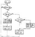
또, 제16도에는 입력된 명령데이터가 정상인 경우에는 제1출력버퍼를 이용하고, 이상이 있는 경우에는 제2출력버퍼를 이용하는 실시예에 관한 플로우챠트가 나타내어져 있다. 즉 IC카드(1)는 입력된 명령데이터의 정당성을 점검하여 정상이면 계속해서 이 명령이 재전송요구명령데이터인지를 판단하게 된다. 이때, 다른 명령데이터이면 그것에 대응하는 처리를 실행하여 그 결과를 제1출력버퍼에 입력시켜 준 다음 제1출력버퍼의 내용을 출력해 주게 된다. 반면에, 재전송요구명령데이터로 판단된 경우에는 곧바로 제1출력버퍼의 내용을 출력해 주게 된다. 그에반해, 입력된 명령데이터에 이상이 있다고 판단되면 그것을 의미하는 응답데이터를 제2출력버퍼를 사용하여 출력해 주게 된다.FIG. 16 shows a flowchart of an embodiment in which the first output buffer is used when the input command data is normal, and the second output buffer is used when there is an error. Namely, the
또한, 제17도에는 입력된 명령데이터가 재전송요구명령데이터라고 인식될 경우에는 제2출력버퍼를 이용하고, 그 이외의 경우에는 제1출력버퍼를 이용하는 실시예에 관한 플로우챠트가 나타내어져 있다. 즉 입력된 명령데이터가 재전송요구명령데이터가 아니라고 인식된 경우에는 그 명령을 점검하여 정상이면 그것에 대한 처리를 실행하여 그 결과를 제1출력버퍼에 입력시킨 다음 제1출력버퍼의 내용을 출력해 주게 된다. 반면에, 명령에 이상이 있으면 그것을 의미하는 응답데이터를 제1출력버퍼에 입력시킨 다음 마찬가지로 제1출력버퍼의 내용을 출력해 주게 된다.FIG. 17 also shows a flowchart of an embodiment in which the second output buffer is used when the input command data is recognized as retransmission request command data, and the first output buffer is otherwise used. In other words, if it is recognized that the input command data is not the retransmission request command data, check the command, and if it is normal, execute the processing for it, input the result to the first output buffer, and then output the contents of the first output buffer. do. On the other hand, if there is an error in the command, the response data, which means it, is input to the first output buffer, and then the contents of the first output buffer are similarly outputted.
그에 반해, 명령이 재전송요구명령데이터라고 인식된 경우에는 마찬가지로 그 명령을 점검하여 정상이면 제1출력버퍼의 내용을 제2출력버퍼로 옮긴 다음 제2출력버퍼의 내용을 출력해 주게 되고, 반면에 이상이 있으면 그것을 의미하는 응답데이터를 제2출력버퍼에 입력시킨 다음 제2출력버퍼의 내용을 출력해 주게 된다.On the other hand, if the command is recognized as retransmission request command data, the command is also checked and if it is normal, the contents of the first output buffer are moved to the second output buffer, and then the contents of the second output buffer are output. If there is a problem, the response data indicating the same is inputted to the second output buffer, and then the contents of the second output buffer are output.
[발명의 효과][Effects of the Invention]
이상 설명한 바와같이 본 발명에 따른 휴대가능전자장치용 처리시스템에 의하면, 카드독출기록기로부터의 명령이 적합하지 않은 경우라던지 전송상의 잡음등에 의해 명령이 정상적으로 수신되지 않은 경우에도 카드독출기록기와 IC카드사이의 시켄스 혼란을 감소시킴과 더불어, 동일한 기능코드를 갖는 명령이 복수회에 걸쳐 연속적으로 송신되는 경우에도 카드독출기록기와 IC카드사이의 시켄스의 혼란을 확실하게 방지할 수 있게 된다.As described above, according to the processing system for a portable electronic device according to the present invention, even when the command from the card reader is not suitable or when the command is not normally received due to transmission noise or the like, the card reader and the IC card In addition to reducing confusion between sequences, even if an instruction having the same function code is transmitted successively in a plurality of times, confusion between sequences between the card reader and the IC card can be reliably prevented.
Claims (5)
Translated fromKoreanApplications Claiming Priority (2)
| Application Number | Priority Date | Filing Date | Title |
|---|---|---|---|
| JP61271201AJPH0746378B2 (en) | 1986-11-14 | 1986-11-14 | IC card |
| JP61-271201 | 1986-11-14 |
Publications (2)
| Publication Number | Publication Date |
|---|---|
| KR880006626A KR880006626A (en) | 1988-07-23 |
| KR910001972B1true KR910001972B1 (en) | 1991-03-30 |
Family
ID=17496753
Family Applications (1)
| Application Number | Title | Priority Date | Filing Date |
|---|---|---|---|
| KR1019870012741AExpiredKR910001972B1 (en) | 1986-11-14 | 1987-11-12 | Processing System for Portable Electronic Devices |
Country Status (5)
| Country | Link |
|---|---|
| US (1) | US4845717A (en) |
| JP (1) | JPH0746378B2 (en) |
| KR (1) | KR910001972B1 (en) |
| DE (1) | DE3732614A1 (en) |
| FR (1) | FR2606904B1 (en) |
Families Citing this family (15)
| Publication number | Priority date | Publication date | Assignee | Title |
|---|---|---|---|---|
| JP2609284B2 (en)* | 1988-05-10 | 1997-05-14 | 株式会社日立製作所 | Distributed timing signal generator |
| JP3028815B2 (en)* | 1988-08-19 | 2000-04-04 | 株式会社東芝 | Transmission method of portable electronic device and portable electronic device |
| US5200600A (en)* | 1988-08-29 | 1993-04-06 | Hitachi Maxell, Ltd. | IC card and method for writing information therein |
| US5068852A (en)* | 1989-11-23 | 1991-11-26 | John Fluke Mfg. Co., Inc. | Hardware enhancements for improved performance of memory emulation method |
| JP2941361B2 (en)* | 1990-06-07 | 1999-08-25 | 株式会社東芝 | Portable electronic devices |
| JP3125070B2 (en)* | 1990-12-14 | 2001-01-15 | 三菱電機株式会社 | IC card |
| JPH05250523A (en)* | 1992-03-06 | 1993-09-28 | Toshiba Corp | Processing system |
| JP3381870B2 (en)* | 1992-11-30 | 2003-03-04 | ヒューレット・パッカード・カンパニー | Mobile computer network adapter |
| JP3421378B2 (en)* | 1993-03-23 | 2003-06-30 | 株式会社東芝 | Transmission control method |
| FR2704704B1 (en)* | 1993-04-28 | 1995-09-01 | Gemplus Card Int | COMMUNICATION SYSTEM. |
| KR100275023B1 (en)* | 1993-09-10 | 2000-12-15 | 사와무라 시코 | Ic card reader/writer and its control method |
| JP3522882B2 (en)* | 1995-03-22 | 2004-04-26 | 株式会社東芝 | Protocol switching method |
| US6304973B1 (en)* | 1998-08-06 | 2001-10-16 | Cryptek Secure Communications, Llc | Multi-level security network system |
| JP3522597B2 (en) | 1999-08-02 | 2004-04-26 | 松下電器産業株式会社 | IC card connection device |
| JP2012208910A (en)* | 2011-03-14 | 2012-10-25 | Toshiba Corp | Portable electronic device and processing system for portable electronic device |
Family Cites Families (9)
| Publication number | Priority date | Publication date | Assignee | Title |
|---|---|---|---|---|
| FR2483657B1 (en)* | 1980-05-30 | 1986-11-21 | Bull Sa | PORTABLE MACHINE FOR CALCULATING OR PROCESSING INFORMATION |
| DE3272316D1 (en)* | 1982-08-30 | 1986-09-04 | Ibm | Device to signal to the central control unit of a data processing equipment the errors occurring in the adapters |
| US4575621A (en)* | 1984-03-07 | 1986-03-11 | Corpra Research, Inc. | Portable electronic transaction device and system therefor |
| JPS60189054A (en)* | 1984-03-07 | 1985-09-26 | Nec Corp | Output buffer control system |
| JPS60207986A (en)* | 1984-04-02 | 1985-10-19 | Toshiba Corp | data processing system |
| US4736094A (en)* | 1984-04-03 | 1988-04-05 | Omron Tateisi Electronics Co. | Financial transaction processing system using an integrated circuit card device |
| JPS60220645A (en)* | 1984-04-18 | 1985-11-05 | Toshiba Corp | Data transmission system |
| US4660198A (en)* | 1985-04-15 | 1987-04-21 | Control Data Corporation | Data capture logic for VLSI chips |
| US4719338A (en)* | 1985-08-12 | 1988-01-12 | Ncr Corporation | Pocket calculator with credit card controller and dispenser |
- 1986
- 1986-11-14JPJP61271201Apatent/JPH0746378B2/ennot_activeExpired - Lifetime
- 1987
- 1987-09-24USUS07/100,762patent/US4845717A/ennot_activeExpired - Lifetime
- 1987-09-28DEDE19873732614patent/DE3732614A1/enactiveGranted
- 1987-09-30FRFR8713534Apatent/FR2606904B1/ennot_activeExpired - Fee Related
- 1987-11-12KRKR1019870012741Apatent/KR910001972B1/ennot_activeExpired
Also Published As
| Publication number | Publication date |
|---|---|
| FR2606904B1 (en) | 1994-02-11 |
| KR880006626A (en) | 1988-07-23 |
| JPS63126083A (en) | 1988-05-30 |
| DE3732614A1 (en) | 1988-05-26 |
| US4845717A (en) | 1989-07-04 |
| DE3732614C2 (en) | 1992-03-26 |
| JPH0746378B2 (en) | 1995-05-17 |
| FR2606904A1 (en) | 1988-05-20 |
Similar Documents
| Publication | Publication Date | Title |
|---|---|---|
| US5161231A (en) | Processing system which transmits a predetermined error code upon detection of an incorrect transmission code | |
| US5414835A (en) | IC card processing system capable of determing send timing between an IC card and an accepting device | |
| KR910001972B1 (en) | Processing System for Portable Electronic Devices | |
| US4939353A (en) | Processing system for enabling data communication with a self-diagnose device | |
| EP0559205B1 (en) | Data processing system | |
| US4983816A (en) | Portable electronic device | |
| US6641045B1 (en) | Portable electronic device with self-diagnostic function | |
| JP7468754B1 (en) | ELECTRONIC INFORMATION STORAGE MEDIUM, IC CHIP, IC CARD, RECEPTION BLOCK PROCESSING METHOD, AND PROGRAM | |
| JPH0772891B2 (en) | Data transmission method | |
| JP2547795B2 (en) | Portable electronic devices | |
| JP7582547B1 (en) | ELECTRONIC INFORMATION STORAGE MEDIUM, IC CHIP, IC CARD, DIVIDED DATA PROCESSING METHOD, AND PROGRAM | |
| JPS62197848A (en) | portable electronic device system | |
| JP2618953B2 (en) | Transmission processing method, data storage medium and IC chip | |
| JPS6383894A (en) | Portable electronic device | |
| JP2577369B2 (en) | IC card | |
| JPS63126084A (en) | Processing method | |
| JP2577370B2 (en) | Portable electronic devices | |
| JP2000115183A (en) | Portable electronic devices | |
| JPS6383892A (en) | Processing method | |
| JP2025091715A (en) | ELECTRONIC INFORMATION STORAGE MEDIUM, IC CHIP, IC CARD, ERROR CODE RESPONSE METHOD, AND PROGRAM | |
| JP2543861B2 (en) | Data transmission method | |
| JP2537198B2 (en) | Portable electronic devices | |
| JP2549639B2 (en) | Data transmission method | |
| JPH01116784A (en) | Processing system | |
| JPS63237188A (en) | Processing method |
Legal Events
| Date | Code | Title | Description |
|---|---|---|---|
| A201 | Request for examination | ||
| PA0109 | Patent application | St.27 status event code:A-0-1-A10-A12-nap-PA0109 | |
| PA0201 | Request for examination | St.27 status event code:A-1-2-D10-D11-exm-PA0201 | |
| R17-X000 | Change to representative recorded | St.27 status event code:A-3-3-R10-R17-oth-X000 | |
| PG1501 | Laying open of application | St.27 status event code:A-1-1-Q10-Q12-nap-PG1501 | |
| E902 | Notification of reason for refusal | ||
| PE0902 | Notice of grounds for rejection | St.27 status event code:A-1-2-D10-D21-exm-PE0902 | |
| P11-X000 | Amendment of application requested | St.27 status event code:A-2-2-P10-P11-nap-X000 | |
| P13-X000 | Application amended | St.27 status event code:A-2-2-P10-P13-nap-X000 | |
| G160 | Decision to publish patent application | ||
| PG1605 | Publication of application before grant of patent | St.27 status event code:A-2-2-Q10-Q13-nap-PG1605 | |
| E701 | Decision to grant or registration of patent right | ||
| PE0701 | Decision of registration | St.27 status event code:A-1-2-D10-D22-exm-PE0701 | |
| GRNT | Written decision to grant | ||
| PR0701 | Registration of establishment | St.27 status event code:A-2-4-F10-F11-exm-PR0701 | |
| PR1002 | Payment of registration fee | St.27 status event code:A-2-2-U10-U11-oth-PR1002 Fee payment year number:1 | |
| PR1001 | Payment of annual fee | St.27 status event code:A-4-4-U10-U11-oth-PR1001 Fee payment year number:4 | |
| PR1001 | Payment of annual fee | St.27 status event code:A-4-4-U10-U11-oth-PR1001 Fee payment year number:5 | |
| PR1001 | Payment of annual fee | St.27 status event code:A-4-4-U10-U11-oth-PR1001 Fee payment year number:6 | |
| PR1001 | Payment of annual fee | St.27 status event code:A-4-4-U10-U11-oth-PR1001 Fee payment year number:7 | |
| PR1001 | Payment of annual fee | St.27 status event code:A-4-4-U10-U11-oth-PR1001 Fee payment year number:8 | |
| R18-X000 | Changes to party contact information recorded | St.27 status event code:A-5-5-R10-R18-oth-X000 | |
| PN2301 | Change of applicant | St.27 status event code:A-5-5-R10-R13-asn-PN2301 St.27 status event code:A-5-5-R10-R11-asn-PN2301 | |
| PR1001 | Payment of annual fee | St.27 status event code:A-4-4-U10-U11-oth-PR1001 Fee payment year number:9 | |
| R18-X000 | Changes to party contact information recorded | St.27 status event code:A-5-5-R10-R18-oth-X000 | |
| R18-X000 | Changes to party contact information recorded | St.27 status event code:A-5-5-R10-R18-oth-X000 | |
| PR1001 | Payment of annual fee | St.27 status event code:A-4-4-U10-U11-oth-PR1001 Fee payment year number:10 | |
| PR1001 | Payment of annual fee | St.27 status event code:A-4-4-U10-U11-oth-PR1001 Fee payment year number:11 | |
| R18-X000 | Changes to party contact information recorded | St.27 status event code:A-5-5-R10-R18-oth-X000 | |
| PR1001 | Payment of annual fee | St.27 status event code:A-4-4-U10-U11-oth-PR1001 Fee payment year number:12 | |
| PR1001 | Payment of annual fee | St.27 status event code:A-4-4-U10-U11-oth-PR1001 Fee payment year number:13 | |
| PR1001 | Payment of annual fee | St.27 status event code:A-4-4-U10-U11-oth-PR1001 Fee payment year number:14 | |
| PR1001 | Payment of annual fee | St.27 status event code:A-4-4-U10-U11-oth-PR1001 Fee payment year number:15 | |
| FPAY | Annual fee payment | Payment date:20060228 Year of fee payment:16 | |
| PR1001 | Payment of annual fee | St.27 status event code:A-4-4-U10-U11-oth-PR1001 Fee payment year number:16 | |
| LAPS | Lapse due to unpaid annual fee | ||
| PC1903 | Unpaid annual fee | St.27 status event code:A-4-4-U10-U13-oth-PC1903 Not in force date:20070331 Payment event data comment text:Termination Category : DEFAULT_OF_REGISTRATION_FEE | |
| PC1903 | Unpaid annual fee | St.27 status event code:N-4-6-H10-H13-oth-PC1903 Ip right cessation event data comment text:Termination Category : DEFAULT_OF_REGISTRATION_FEE Not in force date:20070331 | |
| P22-X000 | Classification modified | St.27 status event code:A-4-4-P10-P22-nap-X000 | |
| R18-X000 | Changes to party contact information recorded | St.27 status event code:A-5-5-R10-R18-oth-X000 |