KR910001274B1 - Optical disc apparatus and data-processing method for optical disc - Google Patents
Optical disc apparatus and data-processing method for optical discDownload PDFInfo
- Publication number
- KR910001274B1 KR910001274B1KR1019860008255AKR860008255AKR910001274B1KR 910001274 B1KR910001274 B1KR 910001274B1KR 1019860008255 AKR1019860008255 AKR 1019860008255AKR 860008255 AKR860008255 AKR 860008255AKR 910001274 B1KR910001274 B1KR 910001274B1
- Authority
- KR
- South Korea
- Prior art keywords
- circuit
- data
- disc
- recording
- mode
- Prior art date
- Legal status (The legal status is an assumption and is not a legal conclusion. Google has not performed a legal analysis and makes no representation as to the accuracy of the status listed.)
- Expired
Links
Images


Classifications
- G—PHYSICS
- G11—INFORMATION STORAGE
- G11B—INFORMATION STORAGE BASED ON RELATIVE MOVEMENT BETWEEN RECORD CARRIER AND TRANSDUCER
- G11B7/00—Recording or reproducing by optical means, e.g. recording using a thermal beam of optical radiation by modifying optical properties or the physical structure, reproducing using an optical beam at lower power by sensing optical properties; Record carriers therefor
- G11B7/24—Record carriers characterised by shape, structure or physical properties, or by the selection of the material
- G11B7/2407—Tracks or pits; Shape, structure or physical properties thereof
- G11B7/24085—Pits
- G—PHYSICS
- G11—INFORMATION STORAGE
- G11B—INFORMATION STORAGE BASED ON RELATIVE MOVEMENT BETWEEN RECORD CARRIER AND TRANSDUCER
- G11B19/00—Driving, starting, stopping record carriers not specifically of filamentary or web form, or of supports therefor; Control thereof; Control of operating function ; Driving both disc and head
- G11B19/20—Driving; Starting; Stopping; Control thereof
- G11B19/28—Speed controlling, regulating, or indicating
- G—PHYSICS
- G11—INFORMATION STORAGE
- G11B—INFORMATION STORAGE BASED ON RELATIVE MOVEMENT BETWEEN RECORD CARRIER AND TRANSDUCER
- G11B20/00—Signal processing not specific to the method of recording or reproducing; Circuits therefor
- G11B20/10—Digital recording or reproducing
- G11B20/12—Formatting, e.g. arrangement of data block or words on the record carriers
- G11B20/1217—Formatting, e.g. arrangement of data block or words on the record carriers on discs
- G11B20/1258—Formatting, e.g. arrangement of data block or words on the record carriers on discs where blocks are arranged within multiple radial zones, e.g. Zone Bit Recording or Constant Density Recording discs, MCAV discs, MCLV discs
- G—PHYSICS
- G11—INFORMATION STORAGE
- G11B—INFORMATION STORAGE BASED ON RELATIVE MOVEMENT BETWEEN RECORD CARRIER AND TRANSDUCER
- G11B7/00—Recording or reproducing by optical means, e.g. recording using a thermal beam of optical radiation by modifying optical properties or the physical structure, reproducing using an optical beam at lower power by sensing optical properties; Record carriers therefor
- G11B7/004—Recording, reproducing or erasing methods; Read, write or erase circuits therefor
- G11B7/005—Reproducing
- G—PHYSICS
- G11—INFORMATION STORAGE
- G11B—INFORMATION STORAGE BASED ON RELATIVE MOVEMENT BETWEEN RECORD CARRIER AND TRANSDUCER
- G11B7/00—Recording or reproducing by optical means, e.g. recording using a thermal beam of optical radiation by modifying optical properties or the physical structure, reproducing using an optical beam at lower power by sensing optical properties; Record carriers therefor
- G11B7/007—Arrangement of the information on the record carrier, e.g. form of tracks, actual track shape, e.g. wobbled, or cross-section, e.g. v-shaped; Sequential information structures, e.g. sectoring or header formats within a track
- G11B7/00745—Sectoring or header formats within a track
Landscapes
- Engineering & Computer Science (AREA)
- Signal Processing (AREA)
- Signal Processing For Digital Recording And Reproducing (AREA)
- Optical Recording Or Reproduction (AREA)
Abstract
Translated fromKoreanDescription
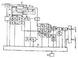
Translated fromKorean제1도는 본 발명의 1실시예에 따른 광디스크장치의 개략적인 블록구성도.1 is a schematic block diagram of an optical disk apparatus according to an embodiment of the present invention.
제2도는 제1도에 도시된 광디스크장치에 사용되는 광디스크의 평면도.FIG. 2 is a plan view of an optical disk used in the optical disk apparatus shown in FIG.
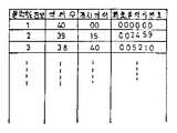
제3도는 제1도의 ROM에 기억된 데이터테이블을 나타낸 도면.3 is a diagram showing a data table stored in the ROM of FIG.
제4도는 광디스크의 트랙반경위치와 클럭신호주파수의 관계를 설명하기 위한 도면.4 is a diagram for explaining a relationship between a track radius position and a clock signal frequency of an optical disc.
제5도는 가변클럭발생회로의 보다 상세한 블럭구성도이다.5 is a more detailed block diagram of the variable clock generation circuit.
* 도면의 주요부분에 대한 부호의 설명* Explanation of symbols for main parts of the drawings
10 : 광디스크장치 12 : 광디스크10: optical disc device 12: optical disc
16 : 블록헤더 18 : 모터16: block header 18: motor
20 : 회전모터구동제어회로 22 : 광학헤드20: rotation motor drive control circuit 22: optical head
24 : 선형모터 26 : 선형모터의 가동부24: linear motor 26: moving part of the linear motor
28 : 선형모터의 고정부 30 : 선형모터구동 및 서보회로28: fixed part of the linear motor 30: linear motor drive and servo circuit
32 : 위치검출기 34 : 제어회로32: position detector 34: control circuit
36 : 외부인터페이스회로 38 : 포커스서보회로36: external interface circuit 38: focus servo circuit
40 : 포커스인입회로 42 : 트랙킹서보회로40: focus inlet circuit 42: tracking servo circuit
44 : 트랙점프펄스발생회로 46 : 비트신호파형정형회로44: track jump pulse generating circuit 46: bit signal waveform shaping circuit
48 : 2치화회로 50 : 기준클럭발생회로48: Binarization Circuit 50: Reference Clock Generation Circuit
52 : 가변클럭발생회로 54 : 재생동기클럭추출회로52: variable clock generation circuit 54: regeneration synchronous clock extraction circuit
56 : 복조회로 58 : 직렬/병렬 변환회로56: demodulation circuit 58: series / parallel conversion circuit
60 : 헤더변별회로 62 : 기록재생 헤더 레지스터60: header discrimination circuit 62: record / play header register
64 : 헤더비교기 66 : 병렬/직렬 변환회로64: header comparator 66: parallel / serial conversion circuit
68 : 기록재생스위칭회로 70 : 변조회로68: recording and playback switching circuit 70: modulation circuit
72 : 레이저구동회로 74 : 기록재생데이터버퍼72: laser drive circuit 74: recording and reproducing data buffer
76 : 기록재생데이터전송회로 78 : 에러정정코드부가 및 에러정정회로76: recording and reproduction data transmission circuit 78: error correction code part and error correction circuit
82 : 분주기(N) 84 : PLL회로82: divider (N) 84: PLL circuit
86 : 위 상비교기 88 : 위상/전압변환회로86: phase comparator 88: phase / voltage conversion circuit
90 : 전압제어발진회로 92 : 분주기(M)90: voltage controlled oscillator circuit 92: divider (M)
[산업상의 이용분야][Industrial use]
본 발명은 디스크장치에 관한 것으로, 특히 광디스크에 대해 정보의 기록 및 독출을 행하도록 된 광디스크장치에 관한 것이다.The present invention relates to a disk device, and more particularly, to an optical disk device configured to record and read information on an optical disk.
[종래의 기술 및 그 문제점][Traditional Technology and Problems]
일반적으로, 광디스크장치에 있어서는 나선상(螺族狀)에 정보를 기록하도록된 광디스크가 사용되는 바, 이 광디스크의 반경방향으로 선형모터(linear motor)에 의해 직선적으로 이동되는 광학헤드로 광디스크에 대해 정보의 기록 또는 재생을 행하도록 되어 있다.In general, in an optical disk apparatus, an optical disk configured to record information in a spiral form is used. The optical disk is an optical head which is linearly moved by a linear motor in the radial direction of the optical disk. Recording or reproducing is performed.
그런데, 이와 같은 광디스크장치의 기록 및 재생에는 다음과 같은 두가지 방식, 즉 회전수 일정방식(Constant Angular Velocity ; 이하, CAV방식이라 칭한다)과 신속도 일정방식(Constant Linear Velocity : 이하 CLV방식이라 칭한다)이 일반적으로 채택되고 있다. 그중 CAV방식은 기록, 재생의 안정화 및 억세스시간을 단축시키기 위해 광디스크의 회전수를 일정하게 해서 기록 또는 재생을 행하도록 되어있다.However, there are two methods for recording and reproducing such an optical disk device, that is, a constant speed constant method (Constant Angular Velocity; hereinafter referred to as a CAV method) and a constant speed constant method (hereinafter referred to as a CLV method). This is generally adopted. Among them, in the CAV system, recording or reproducing is performed at a constant rotation speed of the optical disc in order to stabilize recording, reproduction, and shorten the access time.
또, 이 CAV방식의 경우는 기록 또는 재생타이밍, 즉 복조, 변조주파수도 일정하게 되어 있다. 그에 반해, CLV방식은 광학헤드에 대해 광디스크의 트랙이 항시 등속도로 되도록 광학헤드가 광디스크의 내측으로부터 외측으로 이동함으로써 광디스크의 회전수를 낮게 해서 기록 또는 재생을 행하도록 되어 있다. 이와 같은 CLV방식에서는 고밀도기록이 가능하기는 하지만, 데이터의 기록, 재생을 행하는 경우에 광디스크의 반경방향의 광학헤드의 이동에 대응해서 광디스크의 회전수가 변하기 때문에, 광디스크를 회전시켜주기 위한 모터의 회전수가 안정한 상태로 되기까지 시간이 걸리게 되고, 더 나아가서는 모터를 고속으로 회전시킬 수 없게 된다. 이 때문에, 데이터의 억세스시간이 길어지게 되고, 더 나아가서는 데이터전송속도가 늦어지게 된다.In the CAV system, the recording or reproducing timing, i.e., the demodulation and modulation frequencies are also constant. In contrast, in the CLV method, the optical head is moved from the inside of the optical disc to the outside so that the track of the optical disc is always at the constant speed with respect to the optical head, so that the rotation speed of the optical disc is reduced to perform recording or reproduction. In this CLV method, high density recording is possible, but since the rotation speed of the optical disc changes in response to the movement of the optical head in the radial direction of the optical disc when recording and reproducing data, the rotation of the motor for rotating the optical disc. It takes time for the number to become stable, and furthermore, it becomes impossible to rotate the motor at high speed. For this reason, the data access time becomes long, and further, the data transfer speed becomes slow.
그리고, 억세스시간의 단축화, 기억용량의 증대 및 데이터전송의 고속화를 달성하기 위해 광디스크를 일정한 속도로 회전시키고, 억세스위치에 따라 기록 또는 재생타이밍, 즉 복조, 변조주파수를 변경시킴으로써 기록 또는 재생을 행하는 방식(Modified Constant Angular Velocity : 이하, M-CAV방식이라 칭한다)이 소개되어 실용화되고 있다.Then, the optical disc is rotated at a constant speed in order to shorten the access time, increase the storage capacity, and speed up the data transfer, and perform recording or reproducing by changing the recording or reproducing timing, i.e., demodulation, and modulation frequency according to the access switch. A method (Modified Constant Angular Velocity: hereinafter referred to as M-CAV method) is introduced and put into practical use.
그렇지만, 현재의 광디스크장치에서는 CAV방식의 광디스크를 취급하는 장치와 M-CAV방식의 광디스크를 취급하는 장치는 있지만, 양방식의 광디스크를 취급하는 장치는 없다. 이 때문에, 상기 양방식의 광디스크를 취급할 수 있는 광디스크장치가 요구되고 있다.However, in the present optical disc apparatus, there are devices for handling CAV type optical discs and M-CAV type optical discs, but there are no devices for both types of optical discs. For this reason, there is a demand for an optical disc apparatus capable of handling both types of optical discs.
[발명의 목적][Purpose of invention]
이에 본 발명은 상기와 같은 점을 감안해서 발명된 것으로, CAV방식의 광디스크 및 M-CAV방식의 광디스크를 모두 취급할 수 있도록 된 광디스크장치를 제공하고자 함에 그 목적이 있다.Accordingly, an object of the present invention is to provide an optical disc apparatus capable of handling both a CAV type optical disc and an M-CAV type optical disc.
[발명의 구성][Configuration of Invention]
상기한 목적을 달성하기 위한 본 발명에 따른 광디스크장치는, 제1모드와 제2모드의 양쪽으로부터의 데이터의 재생과 양쪽으로의 데이터의 기록중 적어도 하나를 행하도록 된 디스크장치에서 상기 제1모드의 디스크에는 그 디스크의 반경방향의 위치에 관계없이 일정한 주파수로 데이터가 기록되고, 제2모드의 디스크에는 그 디스크의 반경방향의 위치에 따라 변경되는 주파수로 데이터가 기록되며, 상기 제1 및 제2모드의 디스크는 그 디스크의 모드를 식별하기 위한 식별정보가 디스크(12)의 식별정보기록영역에 기록되어 있고, 상기 디스크(12)를 소청의 회전속도로 회전시키는 회전수단(18,20)과, 상기 회전수단(18,20)에 의해 회전되는 상기 디스크(12)의 식별정보기록영역(C)에 기록된 상기 식별정보를 재생해서 이 식별정보를 기초로 상기 회전수단(18,20)에 의해 회전되는 디스크(12)가 제1모드인지 혹은 제2모드인지를 판정하는 재생수단(34,74) 및, 상기 회전수단(18,20)에 의해 회전되는 디스크(12)가 상기 재생수단(34,74)에 의해 제1모드라고 판정된 경우에는 상기 회전되는 디스크(12)의 반경방향에 관계없이 디스크(12)에 대해 일정주파수(A)로 데이터를 처리하고, 상기 회전수단(18,20)에 의해 회전되는 디스크(12)가 상기 재생수단(34,74)에 의해 제2모드라고 판정된 경우에는 상기 회전되는 디스크(12)의 반경방향에 따라 변경되는 주파수(B)로 디스크(12)에 대해 데이터를 처리하는 처리수단(34,52)으로 구성된 것을 특징으로 한다.An optical disc apparatus according to the present invention for achieving the above object comprises the first mode in a disc apparatus configured to perform at least one of reproduction of data from both of the first mode and the second mode and recording of data to both sides. The data of the disc is recorded at a constant frequency irrespective of the radial position of the disc, and the data of the second mode is recorded at a frequency changed according to the radial position of the disc. In the two-mode disc, identification information for identifying the mode of the disc is recorded in the identification information recording area of the
[실시예]EXAMPLE
이하, 본 발명의 1실시예에 대해 예시도면을 참조해서 상세히 설명한다.Hereinafter, one embodiment of the present invention will be described in detail with reference to the accompanying drawings.
제1도는 본 발명의 1실시예에 따른 광디스크장치의 개략적인 블럭구성도를 나타낸 것으로, 광디스크장치(10)는 광디스크(12)를 기록매체로서 사용한다. 이 광디스크(12)는 제2도에 나타낸 바와 같이 유리 혹은 플라스틱등으로 형성되는 원형기판과, 이 원형기판의 표면에 도넛츠모양으로 코팅되어 있는 텔루르(Tellurium ; 원소기호 Te) 혹은 비스무트(Bismuth ; 원소기호 Bi)등의 금속피막으로 구성되어 있다. 또한, 이 광디스크(12)에는 상기 금속피막의 중앙부근방에 일부분을 절개하여 형성한 기준위치부(14)가 설치되어 있다. 상기 광디스크(12)의 표면은 상기 기준위치부(14)를 "0"으로 하여 "0∼255"까지의 256섹터로 구분되어 있다.1 shows a schematic block diagram of an optical disk apparatus according to an embodiment of the present invention, wherein the optical disk apparatus 10 uses the
상기 광디스크장치(10)에 이용되는 광디스크(12)로서는 CAV방식(변조와 복조의 처리주파수 일정)의 것과 M-CAV방식(변조와 복조의 처리주파수 변경)의 것의 2가지 종류가 있는데, 그중 CAV방식의 광디스크는 내측으로부터 외측을 향해 기록밀도가 높게 되어 있고, 이와 달리 M-CAV방식의 광디스크는 전면의 내측 혹은 외측에서의 기록밀도가 일정하게 되어 있다.There are two types of
이와 같은 CAV방식 혹은 M-CAV방식으로 이용되는 광디스크의 내측부분의 소정위치(식별정보기록영역)에는 변조 및 복조주파수가 억세스위치에 관계없이 일정한지, 또는 변조 및 복주주파수가 억세스위치에 따라 변화하는지를 나타내는 식별정보가 기록되어 있다.Whether the modulation and demodulation frequency is constant regardless of the access switch or the modulation and demodulation frequency is changed depending on the access switch at a predetermined position (identification information recording area) of the inner portion of the optical disk used by the CAV method or the M-CAV method. The identification information indicating whether or not is recorded.
상기 소정위치는 CAV방식의 광디스크에서도 M-CAV방식의 광디스크에서도 동일한 위치에 설정되게 된다. 즉, CAV방식과 M-CAV방식의 광디스크에서의 변조 및 복조 주파수가 동일하고, 또 동일한 기록밀도를 갖는 위치에 상기 소정위치가 설정되게 된다.The predetermined position is set at the same position in the CAV optical disc or the M-CAV optical disc. That is, the predetermined position is set at a position where the modulation and demodulation frequencies of the CAV and M-CAV system optical discs are the same and have the same recording density.
상기 식별정보로서는, 예컨대 CAV방식의 경우에는 "0"이라고 하는 코드가 기록되고, M-CAV방식의 경우에는 "1"이라고 하는 코드가 기록되도록 되어 있다.As the identification information, for example, a code of "0" is recorded in the case of the CAV system, and a code of "1" is recorded in the case of the M-CAV system.
상기 M-CAV방식의 광디스크상의 기록재생단위를 블럭이라 칭하는 바, 하나의 블럭당 고정길이의 데이터가 기록 또는 재생되도록 되어 있다. 여기서, 상기 M-CAV방식의 광디스크에 있어서 하나의 블럭이 점유하는 섹터수는, 예컨대 내측에서 40섹터로 되고, 외측에서는 20섹터로 되도록 되어 있다. 그에 반해, 상기 CAV방식의 광디스크에 있어서 하나의 블럭이 점유하는 섹터수는 일정, 예컨대 40섹터로 되어 있다. 상기 블럭의 개시위치에는 블럭번호와 트랙번호등으로 이루어진 블럭헤더(16)가, 예컨대 광디스크(12)의 제조시에 기록되도록 되어 있다.The recording / reproducing unit on the M-CAV type optical disc is called a block so that fixed-length data per block is recorded or reproduced. In the M-CAV type optical disc, the number of sectors occupied by one block is, for example, 40 sectors on the inside and 20 sectors on the outside. In contrast, in the CAV optical disc, the number of sectors occupied by one block is, for example, 40 sectors. At the start of the block, a
또한, 상기 M-CAV방식의 광디스크에서의 각 블럭이 섹터의 절환위치에서 종료되지 않는 경우에는 블럭갭(block gap)을 설치해서 각 블럭이 반드시 섹터의 절환위치로부터 시작되도록 하고 있다.When each block in the M-CAV type optical disc does not end at the sector switching position, a block gap is provided so that each block always starts from the sector switching position.
이와 같은 광디스크(12)는 제1도에 나타낸 바와 같이 모터(18)에 의해 회전구동되도록 되어 있는데, 이 모터(18)는 후술할 회전모터구동제어회로(20)에 의해 일정한 속도(즉, 600rpm)로 회전이 제어되는 스핀들 모터(spindle motor)로 구성된다.Such an
상기 광디스크(12)의 아랫쪽에는 반대면에 근접하게 정보의 기록 또는 재생을 행하기 위한 광학헤드(22)가 설치되어 있는데, 이 광학헤드(22)는 직류선형모터(24)에 장착되어 있다. 이 직류선형모터(24)는 가동부(26)와 고정부(28)로 구성되어 있고, 상기 광학헤드(22)는 상기 가동부(26)에 고정되어 있다. 또, 상기 선형모터(24)는 선형모터구동 및 서보회로(30)에 접속되고, 그에 따라 상기 선형모터(24)가 구동되면, 상기 가동부(26)가 이동하게 된다.On the lower side of the
이 가동부(26)의 이동에 따라 상기 광학헤드(22)는 상기 광디스크(12)의 반경방향, 즉 화살표로 나타낸 a, b방향으로 선형적으로 이동하게 된다. 이 가동부(26)의 위치, 즉 광학헤드(22)의 위치는 위치검출기(32)에 의해 검출되고, 이 검출결과가 상기 선형모터구동 및 서보회로(30)에 공급되게 된다. 상기 위치검출기(32)는 소위 이중격자형 검출방식에 의해 상기 가동부(26)의 이동량, 즉 광학헤드(22)의 이동량에 따라 2종류의 위상이 다른(이 위상은 방향에 따라 변한다) 검출신호를 출력하게 된다.As the movable part 26 moves, the optical head 22 moves linearly in the radial direction of the
한편, 상기 선형모터(24)에 고정된 광학헤드(22)는 도시되지 않은 예컨대 반도체레이저와 콜리메이터렌즈(collimator lens), 비임스프릿터(beam splitter), 대물렌즈, 해당 대물렌즈를 광디스크(12)의 방향으로 구동시키는 포커스(focus)구동코일, 상기 대물렌즈를 상기 광디스크(12)의 반경방향으로 구동시키는 트랙킹 구동코일, 상기 광디스크(12)에 레이저비임광이 촛점을 모으고 있는지의 여부를 검출하는 1쌍의 광검출기(Photo detector)를 갖춘 촛점일치검출기 및 상기 광디스크(12)의 정보트랙상을 트랙킹하고 있는지의 여부를 검출하는 1쌍의 광검출기를 갖춘 트랙킹검출기로 구성되어 있다. 여기서, 상기 각 광검출기로부터는 후술할 대응되는 처리 및/또는 구동회로로 검지신호가 출력되고, 각 처리 및/또는 구동회로로부터는 각 구동 코일 및 반도체레이저에 소청의 전압이 인가되게 된다.The optical head 22 fixed to the linear motor 24 may include, for example, a semiconductor laser, a collimator lens, a beam splitter, an objective lens, and the corresponding objective lens. A focus driving coil for driving in the direction of a direction, a tracking drive coil for driving the objective lens in a radial direction of the
제어회로(34)는 도시되지 않은 외부장치, 즉 호스트컴퓨터로부터 외부인터페이스회로(36)를 통해 공급되는 제어신호에 따라 해당 광디스크장치(10)를 제어하는 것이고, 상기 모터구동 및 서보회로(30)는 상기 제어회로(34)로부터 공급되는 목표위치신호 및 상기 위치검출기(32)로부터 출력되는 신호에 따라 상기 선헝모터(24)를 구동시키는 것이다.The
그리고, 상기 회전모터구동제어회로(20)는 상기 모터(18)로부터의 회전클럭신호에 따라 모터의 회전속도를 판정하여 상기 제어회로(34)로부터의 설정속도로 속도제어를 행하는 것이고, 포커스서보회로(38)는 상기광학헤드(22)내의 촛점일치검출기로부터 출력되는 검출신호에 따라 상기 광학헤드(22)내의 대물렌즈의 촛점을 조절하는 것이며, 포커스인입회로(40)는 포커스렌즈를 움직이지 않는 상태에서 움직이는 상태로 변경시킬 때에 상기 포커스서보회로(38)에 정확하게 포커싱을 행하기 위한 것이다.The rotation motor drive control circuit 20 determines the rotation speed of the motor according to the rotation clock signal from the motor 18 and performs speed control at a set speed from the
또, 트랙킹서보회로(42)는 상기 광학헤드(22)내의 트랙킹검출기로부터 출력되는 검출신호에 따라 상기 광학헤드(22)내의 대물렌즈를 통해서 발생되는 비임광이 트랙의 중앙으로 집속되도록 상기 대물렌즈를 광디스크(12)의 반경방향으로 이동시키는 것이고, 트랙점프펄스발생회로(44)는 상기 제어회로(34)로부터 공급되는 제어신호에 따라 트랙점프펄스를 발생시키는 것인데, 이 트랙점프펄스가 공급되면 상기 트랙킹서보회로(42)는 서보동작을 일시 정지하고 트랙점프구동펄스를 발해 상기 대물렌즈를 이동시켜 1트랙분의 비임광을 이동시키게 된다.In addition, the tracking servo circuit 42 is configured to focus the beam of light generated through the objective lens in the optical head 22 in accordance with the detection signal output from the tracking detector in the optical head 22 to the center of the track. In the radial direction of the
또한, 비트신호파형정형회로(26)는 상기 광학헤드(22)내의 검출기로부터 출력되는 검출신호를 파형정형는 것이고, 2치화회로(48 : 二値化回路)는 상기 비트신호파형정형회로(46)로부터 출력되는 파형정형신호를 2치화하는 것이다.In addition, the bit signal waveform shaping circuit 26 waveform-shapes the detection signal output from the detector in the optical head 22, and the binarization circuit 48 is the bit signal waveform shaping circuit 46. This is to binarize the waveform shaping signal output from the system.
그리고, 기준클럭발생회로(50)는 기준클럭신호를 발생시키는 것이고, 가변클럭발생회로(52)는 상기 기준 클럭발생회로(50)로부터 공급되는 기준클럭을 기초로 상기 제어회로(34)로부터 공급되는 클럭속도정보에 따라 주파수(즉, 시간폭)의 클럭신호(기준신호)를 발생시키는 것이다. 이 경우, 상기 가변클럭발생회로(52)에서 발생되는 클럭신호의 주파수는 상기 광학헤드(22)의 위치가 상기 광디스크의 외측방향으로 이동됨에 따라 높아지게(즉, 시간폭이 짧아지게) 된다.The reference
또, 재생동기클럭추출회로(54)는 상기 제어회로(34)로부터의 제어신호가 공급될 경우, 상기 가변클럭발생회로(52)로부터 공급되는 클럭신호의 주파수근방의 범위내에서 상기 2차회로(48)로부터 공급되는 데이터로부터 재생동기클럭신호를 추출해내는 것이고, 복조회로(56)는 상기 재생동기클럭추출회로(54)로부터의 재생동기클럭신호를 사용하여 상기 2치화회로(48)로부터 공급되는 데이터를 MFM복조하는 것이며, 직렬/병렬 변환회로(58)는 상기 복조회로(56)로부터 공급되는 재생신호를 직렬데이터로부터 병렬데이터로 변환시키는 것이다.Further, when the control signal from the
또한, 헤더변별회로(60)는 상기 복조회로(56)로부터 공급되는 재생신호로부터 헤더데이터만을 변별하는것이고, 기록재생헤더레지스터(62)는 상기 제어회로(34)로부터 공급되는 억세스되어야 할 헤더데이터를 기억하는 것이며, 헤더비교기(64)는 상기 기록재생헤더레지스터(62)에 기억된 헤더데이터와 상기 헤더변별회로(60)로부터 공급되는 헤더데이터가 일치하는가를 비교해서 일치할 때 일치신호를 출력하는 것이다.In addition, the header discrimination circuit 60 discriminates only the header data from the playback signal supplied from the demodulation circuit 56, and the recording / playback header register 62 is the header to be accessed supplied from the
그리고, 병렬/직렬변환회로(66)는 후술할 기록재생스위칭회로(68)로부터 공급되는 기록데이터를 상기 가변클럭발생회로(52)로부터 공급되는 클럭신호에 따라 병렬데이터로부터 직렬데이터로 변환시키는 것이고, 변조회로(70)는 상기 병렬/직렬변환회로(66)로부터 공급되는 데이터를 상긴 가변클럭발생회로(52)로부터 공급되는 클릭신호에 따라 MFM변조하는 것이며, 레이저구동회로(72)는 상기 변조회로(70)로부터 공급되는 변조신호에 따라 상기 광학헤드(22)내의 반도체레이저를 구동제어함으로써 상기 광디스크(12)에 데이터의 기록을 행하는 것이다.The parallel /
또, 상기 기록재생스위칭회로(68)는 상기 제어회로(34)로부터 공급되는 재생제어신호에 따라 상기 헤더비교기(64)로부터 일치신호가 공급될 때, 상기 직렬/병렬변환회로(58)로부터 공급되는 헤더데이터에 잇따르는 재생데이터를 기록재생데이터버퍼(74)에 출력하고, 또 상기 제어회로(34)로부터의 기록제어신호에 따라 상기 헤더비교기(64)로부터 일치신호가 공급될 때, 기록데이터를 상기 병렬/직렬변환회로(66)에 출력하는 것이다.The recording / reproducing switching circuit 68 is supplied from the serial / parallel conversion circuit 58 when a matching signal is supplied from the header comparator 64 in accordance with the reproduction control signal supplied from the
또한, 상기 기록재생데이터버퍼(74)는 상기 기록재생스위칭회로(68)로부터 공급되는 재생데이터를 기억함과 더불어 후술할 기록재생데이터전송회로(76)로부터의 기록데이터를 기억하는 것이고, 에러정정코드부가 및 에러정정회로(78)는 상기 기록재생데이터버퍼(74)에 기억되는 기록데이터에 에러코드를 부가함과 더불어 상기 기록재생데이터버퍼(74)에 기억되는 재생데이터의 에러를 정정하는 것이며, 상기 기록재생데이터전송회로(76)는 상기 기록재생데이터버퍼(74)로부터 공급되는 재생데이터를 상기 외부인터페이스회로(36)를 통해 도시되지 않은 상기 호스트컴퓨터에 전송함과 더불어 상기 호스트컴퓨터로부터 상기 외부인터페이스회로(36)를 통하여 공급되는 기록데이터를 상기 기록재생데이터버퍼(74)에 출력하는 것이다. 여기서, 기동시에 광디스크모드를 판별할 때에는, 상기 기록재생데이터버퍼(74)로부터 출력되는 재생데이터(식별정보)는 상기기록재생데이터 전송회로(76)가 아니라 상기 제어회로(34)로 출력되도록 되어 있다.The recording / playback data buffer 74 also stores the playback data supplied from the recording / playback switching circuit 68, and also stores the recording data from the recording / playback data transmission circuit 76 to be described later, and an error correction code. The addition and
그리고, 기억회로서의 ROM(80)은 제3도에 나타낸 바와 같이 256트랙마다의 광디스크(12)의 클럭속도정보와, 이 클럭속도에서의 1블럭의 섹터수, 상기 속도에서의 256트랙내의 최초블럭의 번호 및, 그 블럭의 개시섹터가 대응된 데이터테이블을 기억하고 있는 것이다.As shown in FIG. 3, the ROM 80 as a storage memory has clock speed information of the
상기 제어회로(34)는 기동시의 광디스크모드를 판별할 때, 상기 기록재생데이터버퍼(74)로부터 공급되는 재생데이터(식별 정보)에 따라 광디스크장치(10)에 설정된 광디스크(12)가 CAV방식의 광디스크인지 M-CAV방식의 광디스크인지를 판별하게 된다.When the
예컨대, 상기 식별정보로서 "0"이라고 하는 코드가 상기 기록재생데이터버퍼(74)로부터 공급된 경우에는 CAV방식의 광디스크(12)가 설정되었다고 판단하고, 이와 달리 상기 식별정보로서 "1"이라고 하는 코드가 상기 기록재생데이터버퍼(74)로부터 공급된 경우에는 M-CAV방식의 광디스크(12)가 설정되었다고 판단하게 된다.For example, when a code of "0" is supplied from the recording / playback data buffer 74 as the identification information, it is determined that the
상기 판단결과에 따라 상기 제어회로(34)는 상기 가변클럭발생회로(52)로부터 출력되는 클럭신호가 억세스위치에 관계없이 일정하게 되는 제1모드와 클럭신호가 억세스위치에 따라 변경되는 제2모드중에서 어느하나를 선택하게 된다.According to the determination result, the
즉, CAV방식의 경우에는 상기 제1모드가 선택되고, M-CAV방식의 경우에는 상기 제2모드가 선택되게 된다. 예컨대, 상기 제1모드가 선택된 경우에는 제4도에 파선(A)으로 나타낸 바와 같이 상기 광디스크(12)의 억세스위치에 관계없이 일정한 주파수의 클럭신호가 상기 가변클럭발생회로(52)로부터 출력되도록 상기 제어회로(34)가 상기 가변클럭발생회로(52)를 제어하게 된다.That is, in the case of the CAV method, the first mode is selected, and in the case of the M-CAV method, the second mode is selected. For example, when the first mode is selected, as shown by a broken line A in FIG. 4, a clock signal having a constant frequency is output from the variable
그에 반해, 상기 제2모드가 선택된 경우에는 제4도에 실선(B)으로 나타낸 바와 같이 상기 광디스크(12)의 억세스위치에 따라 변경되는 주파수의 클럭신호가 상기 가변클럭발생회로(52)로부터 출력되도록 상기 제어회로(34)가 상기 가변클럭 발생회로(52)를 제어하게 된다. 이 경우, 섹터수가 같은 블럭에 대한 클럭신호의 주파수는 같아지게 되고, 그에 따라 그 주파수변화는 도시된 바와 같이 계단형태로 되게 된다. 여기서, 상기 시별정보는 제4도에 도시된 바와 같이 상기 제1모드와 제2모드에서 같은 주파수의 클럭신호가 출력되는 기록영역(C)에 기록되게 된다.On the contrary, when the second mode is selected, the clock signal of the frequency changed according to the access switch of the
또, 상기 제어회로(34)는 상기 호스트컴퓨터로부터 상기 외부인터페이스회로(36)를 통해 기록 또는 재생되는 위치, 즉 억세스하는 위치의 블럭번호가 공급될 때, 상기 제1모드의 경우에서는 그 블럭번호에 따른 억세스위치를 상기 ROM(80)으로부터 독출해서 상기 클럭신호의 주파수를 일정하게 한 상태에서 상기 선헝모터(24)와 광학헤드(22)에 의한 억세스를 행하게 된다.Further, when the
또, 상기 제2모드의 경우에서는 그 블럭번호에 따른 클럭속도정보 및 억세스위치를 상기 ROM(80)으로부터 독출해서 이 억세스신호에 따른 클럭신호를 출력한 상태에서 상기 선형모터(24)와 광학헤드(22)에 의한 억세스를 행하게 된다. 상기 클럭속도정보 및 억세스위치의 독출(산출)에 관해서는 1985년 2월 22일에 출원되어 주시회사 도시바(東芝)에 양도된 T.YOSHIMARU에 의한 미국특허출원 제704,466호(EPC 특허출원 제85101982.8호)에 게재된 "광디스크장치(Optical Disc Device)"에 상세히 설명되어 있으므로 여기서는 그 설명을 생략하기로 한다.In the case of the second mode, the linear motor 24 and the optical head in a state in which clock speed information and an access switch corresponding to the block number are read from the ROM 80 and a clock signal corresponding to the access signal is output. Access by (22) is performed. Regarding the reading and calculation of the clock speed information and the access switch, US Patent Application No. 704,466 issued by T.YOSHIMARU filed on February 22, 1985 and assigned to Toshiba Co., Ltd. (EPC Patent Application No. 85101982.8 It is described in detail in the "Optical Disc Device" published in No.), so the description thereof will be omitted here.
또한, 상기 가변클럭발생회로(52)는 제5도에 나타낸 바와 같이, 분주기(82)와 위상비교기(86), 위상/전압변환회로(88), 전압제어발진회로(90) 및 분주기(92)로 이루어 진 PLL회로(84)로 구성되어 있다. 즉, 상기 제어회로(34)에 의해 상기 PLL회로(84)내의 분주기(92)의 분주수를 제어함으로써 상기 PLL회로(84)의 출력, 즉 클럭신호의 주파수를 제어하게 된다.As shown in FIG. 5, the variable
이하, 이와 같은 구성의 광디스크장치(10)의 동작을 상세히 설명한다.Hereinafter, the operation of the optical disk device 10 having such a configuration will be described in detail.
광디스크(12)가 이 광디스크장치(10)에 설정되면, 상기 제어회로(34)는 상기 회전모터구동제어회로(20)에 제어신호를 공급해서 상기 모터(18)를 구동시켜 상기 광디스크(12)를 일정(소정의)속도로 회전시키게 된다. 그 다음에 상기 제어회로(34)는 제4도에 도시된 식별정보기록영역(C)내에 설치된 식별정보기록블럭에 대응하는 블럭번호에 따른 클럭속도정보 및 억세스위치, 즉 트랙번호와 개시섹터번호를 상기 ROM(80)으로부터 독출하게 된다.When the
그리고, 상기 제어회로(34)는 독출한 상기 클럭속도정보를 상기 가변클럭발생회로(52)에 출력하게 된다. 그러면, 상기 가변클럭발생회로(52)는 상기 기분클럭발생회로(50)로부터 공급되는 기준클럭을 이용하여 상기 제어회로(34)로부터 공급되는 상기 클럭속도정보에 따른 주파수(시간폭)의 클럭신호를 발생시켜 그것을 상기 재생동기클럭추출회로(54)와 복조회로(56), 직렬/병렬변환회로(58), 헤더변별회로(60), 병렬/직렬변환회로(66) 및 변조회로(70)에 공급하게 된다.The
또, 상기 제어회로(34)는 상기 ROM(80)으로부터 독출한 상기 트랙번호를 스케일(scale)값으로 변환시켜 상기 선형모터구동 및 서보회로(30)에 공급하게 된다. 상기 위치검출기(32)의 출력에 따라 검출되는 위치가 일치할 때까지 상기 선헝모터(24)를 구동시킴으로써 상기 광학헤드(22)를 이동시키게 된다. 그 다음에 상기광학헤드(22)의 이동이 종료되면 상기 광학헤드(22)내의 상기 검출기로부터 출력되는 검출신호는 상기 비트신호파형정형회로(46)에 의해 파형정형되고, 상기 2치화회로(48)에 의해 2치화되어 상기 재생동기클럭추출회로(54) 및 복조회로(56)에 공급되게 된다. 상기 재생동기클럭추출회로(54)는 공급되는 데이터로부터 재생동기클럭을 추출해서 이것을 상기 복조회로(56)에 출력하게 된다.In addition, the
상기 복조회로(56)는 상기 재생동기클럭추출회로(54)로부터 공급되는 재생동기클럭을 사용해서 상기 2치화회로(48)로부터 공급되는 독출데이터를 MFM복조하게 된다. 그리고, 이렇게 MFM복조된 상기 복조회로(56)의 출력은 상기 직렬/병렬변환회로(58)를 통하여 상기 기록재생스위칭회로(68)에 공급됨과 더불어 상기헤더변별회로(60)에 공급되게 된다.The demodulation circuit 56 performs MFM demodulation of the read data supplied from the binarization circuit 48 using the regeneration synchronous clock supplied from the regeneration synchronous clock extraction circuit 54. The output of the MFM demodulated circuit 56 is supplied to the recording and reproducing switching circuit 68 through the serial / parallel conversion circuit 58 and to the header discriminating circuit 60. .
상기 헤더변별회로(60)는 공급되는 복조출력으로부터 헤더데이터(트랙번호)만을 변별하여 이것을 상기 제어회로(34)에 출력하게 되고, 상기 제어회로(34)는 이 헤더데이터로부터 상기 광학헤드(22)가 대응하고 있는(위치하고 있는) 트랙을 판단하여 이 트랙과 목적하는 트랙을 비교하게 되는데, 이때 수 10트랙이상 떨어져 있다고 판단된 경우에는 상기 제어회로(34)가 상기 선형모터(24)에 의해 재차 상기 광학헤드(22)를 이동시키게 되고, 또 수 10트랙이내라고 판단된 경우에는 상기 제어회로(34)가 트랙점프펄스발생회로(44)에 제어신호를 공급해서 트랙점프신호에 의해 상기 광학헤드(22)를 대응하는 트랙(목적하는 트랙)의 수치만큼 이동시키게 된다.The header discriminating circuit 60 discriminates only the header data (track number) from the supplied demodulation output and outputs it to the
이와 같이 해서 목적하는 트랙에 상기 광학헤드(22)가 대응되었을 때, 상기 헤더변별회로(60)는 헤더데이터(블럭번호, 개시섹터번호)만을 변별하여 상기 헤더비교기(64)에 출력하게 된다.In this way, when the optical head 22 corresponds to the desired track, the header discrimination circuit 60 discriminates only the header data (block number, starting sector number) and outputs them to the header comparator 64.
이때, 상기 기록재생헤더레지스터(62)에는 목적하는, 즉 식별정보기록영역(C)내에 설치된 식별정보기록블럭의 헤더데이터가 상기 제어회로(34)에 의해 미리 기억되어 있고, 상기 헤더비교기(64)에는 상기 기록재생헤더레지스터(62)의 헤더데이터도 공급되어 있다. 그에 따라, 상기 헤더비교기(64)는 상기 헤더데이터를 비교하여 일치할 때에는 일치신호를 상기 기록재생스위칭회로(68)에 출력하게 된다. 이 일치신호에 따라 상기 기록재생스위칭회로(68)는 상기 직렬/병렬변환회로(58)로부터 공급되는 헤더데이터에 잇따라 공급되는 재생데이터를 상기 기록재생데이터버퍼(74)에 출력하게 된다.At this time, in the recording / reproducing header register 62, header data of an identification information recording block of interest, that is, installed in the identification information recording area C, is stored in advance by the
또, 상기 기록재생데이터버퍼(74)의 재생데이터는 상기 에러정정코드부가 및 에러정정회로(78)에 의해 에러정정이 행해진 후에 상기 제어회로(34)에 공급되게 된다. 상기 제어회로(34)는 이 공급된 재생데이터(즉,식별정보)가 "0"인 경우에는 CAV방식의 광디스크가 설정된 것이라고 판단해서 상기 제1모드를 선택하게된다.The reproduction data of the recording / reproducing data buffer 74 is supplied to the
따라서, 제4도에 파선(A)으로 나타낸 바와 같이 광디스크(12)의 억세스위치에 관계없이 일정한 주파수의 클럭신호가 상기 가변클럭발생회로(52)로부터 출력되도록 상기 가변클럭발생회로(52)를 제어하게 된다.Therefore, as shown by the broken line A in FIG. 4, the variable
그에 반해, 상기 재생데이터버퍼(74)로부터 공급된 재생데이터(즉, 식별정보)가 "1"인 경우에는, 상기제어회로(34)는 M-CAV방식의 광디스크가 설정된 것이라고 판단해서 상기 제2모드를 선택하게 된다. 따라서, 제4도에 실선(B)으로 나타낸 바와 같이 광디스크(12)의 억세스위치에 따라 변경되는 주파수의 클럭신호가 상기 가변클럭발생회로(52)로부터 출력되도록 상기 가변클럭발생회로(52)를 제어하게 된다.On the other hand, when the reproduction data (i.e., identification information) supplied from the reproduction data buffer 74 is "1", the
이하, 상기와 같이 해서 제1모드가 선택된 경우에 있어서의 데이터의 기록에 대해 설명한다.Hereinafter, the recording of data in the case where the first mode is selected as described above will be described.
즉, 상기 호스트컴퓨터로부터 상기 외부인터페이스회로(36)를 통해 기록을 행할(즉, 억세스할) 블럭번호가 상기 제어회로(34)에 공급되었다고 가정한다.In other words, it is assumed that a block number for writing (i.e., accessing) from the host computer via the
그러면, 상기 제어회로(34)는 상기 ROM(80)의 변환테이블을 이용하여 목적으로 하는 블럭의 트랙과 개시섹터를 산출하게 된다. 또, 상기 제어회로(34)는 제1모드가 선택되어 있기 때문에 상기 가변클럭발생회로(52)로부터 억세스위치에 관계없이 일정한 주파수의 클럭신호가 출력되도록 제어하게 된다. 그에 따라, 그 일정주파수의 클럭신호는 상기 재생동기클럭추출회로(54)와 복조회로(56), 직렬/병렬변환회로(58), 헤더변별회로(60), 병렬/직렬변환회로(66) 및 변조회로(70)에 공급되게 된다.Then, the
또한, 상기 트랙번호에 의해 상기 제어회로(34)는 상술한 바와 같은 상기 식별정보기록영역(C)내에 설치된 식별정보기록블럭을 억세스하는 경우와 마찬가지로 동작해서 목적하는 블록이 존재하는 트랙에 상기 광학헤드(22)의 비임광이 대응되도록 제어하게 된다.In addition, the
이때, 기록데이터는 상기 호스트컴퓨터로부터 상기 외부인터페이스회로(36) 및 기록재생데이터전송회로(76)를 통하여 상기 기록재생데이터버퍼(74)에 기억되게 된다. 더욱이, 이 기록데이터는 상기 에러정정코드부가 및 에러정정회로(78)에 의해 에러코드가 부가되게 된다.At this time, the recording data is stored in the recording / reproducing data buffer 74 from the host computer via the
상기 기록재생데이터버퍼(74)에 기억된 기록데이터는 상기 목적하는 블럭의 블럭헤더의 일치신호가 상기헤드비교기(64)로부터 상기 기록재생스위칭회로(68)에 공급될 때 상기 기록재생스위칭회로(68)에 의해 상기 병렬/직렬변환회로(66)에 공급되고, 이 병렬/직렬변환회로(66)에서 직렬데이터로 변환된 기록데이터는 상기변조회로(70)에 의해 MFM변조가 행해진 다음에 상기 레이저구동회로(72)에 공급되게 된다. 상기 레이저구동회로(72)는 공급되는 변조신호에 따라 상기 광학헤드(22)내의 반도체레이저를 구동시켜 데이터의 기록을 행하게 된다.The recording data stored in the recording / reproducing data buffer 74 is recorded when the matching signal of the block header of the target block is supplied from the head comparator 64 to the recording / playing switching circuit 68. 68, supplied to the parallel /
또한, 다른 블럭에 데이터를 기록하는 경우에도 상기와 마찬가지로해서 데이터의 기록을 행하도록 되어있다. 이 경우, 상기 블럭위치가 변경되더라도 클럭신호의 주파수가 일정한 상태에서 데이터의 기록이 행해지게 된다.Also, in the case where data is recorded in another block, the data is recorded in the same manner as described above. In this case, even if the block position is changed, data is recorded while the frequency of the clock signal is constant.
이어, 데이터의 재생동작에 대해서 설명하면 다음과 같다. 즉, 상기 호스트컴퓨터로부터 상기 외부인터페이스회로(36)를 통해 재생(즉, 억세스)할 블럭번호가 상기 제어회로(34)에 공급되었다고 가정한다.Next, the data reproducing operation will be described. In other words, it is assumed that a block number to be reproduced (that is, accessed) from the host computer through the
그러면, 상기 데이터의 기록과 마찬가지로 해서 목적하는 블럭이 존재하는 트랙에 상기 광학헤드(22)의 비임광이 대응되게 된다.Then, in the same manner as the recording of the data, the non-light of the optical head 22 corresponds to the track in which the target block exists.
상기 목적하는 블럭의 블럭헤더의 일치신호가 상기 헤드비교기(64)로부터 상기 기록재생스위칭회로(68)로 공급될 때, 그 기록재생스위칭회로(68)에 의해 상기 직렬/병렬변환회로(58)로부터 출력되는 재생데이터가 상기 기록재생데이터버퍼(74)에 공급되게 되고, 이 기록재생데이터버퍼(74)에 기억된 재생데이터는 에러정정코드부가 및 에러정정회로(78)에 인가되어 에러가 정정된 후에 기록재생데이터전송회로(76) 및 외부인터페이스회로(36)를 통해 상기 호스트컴퓨터로 전송되게 된다.When the matching signal of the block header of the desired block is supplied from the head comparator 64 to the recording / playing switching circuit 68, the serial / parallel conversion circuit 58 by the recording / playing switching circuit 68 The reproduction data output from the data is supplied to the recording reproduction data buffer 74, and the reproduction data stored in the recording reproduction data buffer 74 is applied to the error correction code portion and the
또한, 다른 블럭의 데이터를 재생하는 경우에도 상기와 마찬가지로해서 데이터의 재생을 행하도록 되어있다. 이 경우, 상기 블럭위치가 변경되더라도 클럭신호의 주파수가 일정한 상태에서 데이터의 재생이 행해지게 된다.Also, in the case of reproducing data of another block, the data is reproduced in the same manner as above. In this case, even if the block position is changed, data is reproduced in a state where the frequency of the clock signal is constant.
다음에는 상기와 같이 해서 제2모드가 선택된 경우에 있어서의 데이터의 기록동작에 대해 설명한다.Next, the data recording operation in the case where the second mode is selected as described above will be described.
즉, 상기 호스트컴퓨터로부터 상기 외부인터페이스회로(36)을 통해 기록(즉, 억세스)할 블럭번호가 상기제어회로(34)에 공급되었다고 가정한다. 그러면, 상기 제어회로(34)는 ROM(80)의 변환테이블을 이용하여 목적으로 하는 블락의 트랙과 개시섹터 및 클럭속도정보를 산출하게 되고, 이렇게 산출된 클럭속도정보를 상기 가변클럭발생회로(52)에 출력하게 된다.In other words, it is assumed that a block number to be recorded (that is, accessed) from the host computer via the
상기 가변클럭발생회로(52)는 기준클럭발생회로(50)로부터 공급되는 기준클럭을 이용해서 상기 제어회로(34)로부터 공급되는 클럭속도정보에 따른 주파수의 클럭신호를 발생시키게 되고, 이렇게 발생된 클럭신호는 재생동기클럭추출회로(54)와 복조회로(56), 직렬/병렬변환회로(58), 헤더변환회로(60), 병렬/직렬변환회로(66) 및 변조회로(70)에 공급되게 된다. 또, 상기 제어회로(34)는 상기 트랙번호에 의해 상술한 바와같이 상기 식별정보기록영역(C)내에 설치된 식별정보기록블럭을 억세스하는 경우와 마찬가지로 동작해서 목적하는 블록이 존재하는 트랙에 상기 광학헤드(22)의 비임광을 대응시키게 된다.The variable
이때, 기록데이터는 상기 호스트컴퓨터로부터 상기 외부인터페이스회로(36) 및 기록재생데이터전송회로(76)를 통하여 상기 기록재생데이터버퍼(74)에 기억되게 된다. 더욱이, 이 기록데이터는 상기 에러정정코드부가 및 에러정정회로(78)에 의해 에러정정코드가 부가되게 된다.At this time, the recording data is stored in the recording / reproducing data buffer 74 from the host computer via the
상기 기록재생데이터버퍼(74)에 기록된 기록데이터는 상기 목적하는 블록의 블록헤더의 일치신호가 헤더비교기(64)로부터 상기 기록재생스위칭회로(68)에 공급될 때, 상기 기록재생스위칭회로(68)에 의해 상기 병렬/직렬변환회로(66)에 의해 공급되게 된다.The recording data recorded in the recording reproduction data buffer 74 is supplied with the recording reproduction switching circuit when the coincidence signal of the block header of the target block is supplied from the header comparator 64 to the recording reproduction switching circuit 68. 68) to be supplied by the parallel /
이 병렬/직렬변환회로(66)에 의해 직렬데이터로 변환된 기록데이터는 상기 변조회로(70)에 의해 MFM 변조되어 상기 레이저구동회로(72)에 공급되게 된다. 상기 레이저구동회로(72)는 공급되는 변조신호에 따라 광학헤드(22)내의 반도체레이저를 구동시켜 데이터의 기록을 행하게 된다.The recording data converted into serial data by this parallel /
또한, 다른 블럭에 데이터를 기록하는 경우에도 상기와 마찬가지로 해서 행하도록 되어 있다. 이 경우, 상기 블럭위치가 외주측에 위치함에 따라 클럭신호의 주파수를 높게 한 상태에서 데이터의 기록이 행해지게 된다.In the case where data is recorded in another block, the same operation as described above is performed. In this case, as the block position is located on the outer circumferential side, data recording is performed while the frequency of the clock signal is increased.
이어, 데이터의 재생에 대해 설명하면 다음과 같다.Next, the reproduction of data will be described.
즉, 상기 호스트컴퓨터로부터 상기 외부인터페이스(36)를 통해 재생(즉, 억세스)할 블럭신호가 상기 제어 회로(34)에 공급되었다고 가정한다. 그러면, 상기 제어회로(34)는 상기 기록의 경우와 마찬가지로 해서 그 블록번호에 대응하는 클럭속도정보를 독출해서 이 클럭속도정보에 따른 주파수의 클럭신호가 발생되도록 상기 가변클럭발생회로(54)를 제어하게 된다. 상기 가변클럭발생회로(52)에서 발생된 클럭신호는 상기 재생동기클럭추출회로(54)와 복조회로(56), 직렬/병렬변환회로(58), 헤더변환회로(60), 병렬/직렬변환회로(66) 및 변조회로(70)에 공급되게 된다. 또, 상기 데이터의 기록동작과 마찬가지로 해서 목적하는 블럭이 존재하는 트랙에 상기 광학헤드(22)의 비임광을 대응시키게 된다.In other words, it is assumed that a block signal to be reproduced (that is, accessed) from the host computer via the
상기 목적하는 블럭의 블럭헤더의 일치신호가 상기 헤더비교기(64)로부터 상기 기록재생스위칭회로(68)에 공급될 때, 상기 기록재생스위칭회로(68)에 의해 상기 직렬/병렬변환회로(58)로부터 출력되는 재생데이터가 상기 기록재생데이터버퍼(74)에 공급되게 되고, 이 기록재생데이터버퍼(74)에 기억된 재생데이터는 상기 에러정정코드부가 및 에러정정회로(78)에 인가된어 에러가 정정된 다음 상기 기록재생데이터전송회로(76) 및 외부인터페이스회로(36)를 통해 상기 호스트컴퓨터로 전송되게 된다.When the matching signal of the block header of the desired block is supplied from the header comparator 64 to the recording / playing switching circuit 68, the serial / parallel conversion circuit 58 by the recording / playing switching circuit 68 The reproduction data outputted from the recording reproduction data buffer 74 is supplied to the recording reproduction data buffer 74, and the reproduction data stored in the recording reproduction data buffer 74 is applied to the error correction code portion and the
또한, 다른 블록의 데이터를 재생하는 경우에도 상기와 마찬가지로 해서 행하도록 되어 있다. 이 경우, 상기 블록위치가 광디스크의 외주측에 위치함에 따라 클럭신호의 주파수를 높게 한 상태에서 데이터의 재생이 행해지게 된다.In the case of reproducing data of another block, the same operation is performed as described above. In this case, as the block position is located on the outer circumferential side of the optical disc, data is reproduced while the frequency of the clock signal is increased.
이상 설명한 바와 같이 상기 광디스크장치(10)는 광디스크(12)를 설정하는 기동시(초기설정시)에 소정의 주파수의 클럭신호를 변조수단과 복조수단에 대해 출력해서 그 설정된 광디스크(12)의 소정위치, 즉 식별정보기록영역(C)내에 설치된 식별정보블럭에 기록되어 있는 클럭신호의 주파수가 일정한지, 변경되는지를 나타내는 식별정보를 독출하게 되고, 이 독출된 식별정도에 따라 상기 클럭신호의 주파수를 일정 혹은 광디스크(12)의 억세스위치에 따른 주파수로 변경해서 기록, 재생을 행하도록 되어 있다. 따라서, CAV방식의 광디스크와 M-CAV방식의 광디스크 모두를 취급할 수 있게 된다.As described above, the optical disc apparatus 10 outputs a clock signal of a predetermined frequency to the modulation means and the demodulation means at the time of startup (initial setting) for setting the
상기 식별정보기록영역(C)은 기록밀도가 같은 영역이면 좋다. 따라서, 기록밀도가 같은 영역이라면, 제1모드와 제2모드시에는 회전모터의 회전수를 다르게 해도 좋은 바, 이 경우에는 종래의 CLV방식도 사용 할 수 있게 된다.The identification information recording area C may be an area having the same recording density. Therefore, if the recording density is the same, the rotational speed of the rotating motor may be different in the first mode and the second mode. In this case, the conventional CLV method can be used.
[발명의 효과][Effects of the Invention]
이상 설명한 바와 같이 본 발명에 의하면, CAV방식의 광디스크와 M-CAV방식의 광디스크 모두를 취급할 수 있는 광디스크장치를 제공할 수 있게 된다.As described above, according to the present invention, it is possible to provide an optical disk apparatus capable of handling both a CAV optical disk and an M-CAV optical disk.
Claims (1)
Translated fromKoreanApplications Claiming Priority (3)
| Application Number | Priority Date | Filing Date | Title |
|---|---|---|---|
| JP60-220579 | 1985-10-03 | ||
| JP220579 | 1985-10-03 | ||
| JP60220579AJPH06101199B2 (en) | 1985-10-03 | 1985-10-03 | Disk device |
Publications (2)
| Publication Number | Publication Date |
|---|---|
| KR870004420A KR870004420A (en) | 1987-05-09 |
| KR910001274B1true KR910001274B1 (en) | 1991-02-26 |
Family
ID=16753186
Family Applications (1)
| Application Number | Title | Priority Date | Filing Date |
|---|---|---|---|
| KR1019860008255AExpiredKR910001274B1 (en) | 1985-10-03 | 1986-10-02 | Optical disc apparatus and data-processing method for optical disc |
Country Status (5)
| Country | Link |
|---|---|
| US (1) | US4896311A (en) |
| EP (1) | EP0218214B1 (en) |
| JP (1) | JPH06101199B2 (en) |
| KR (1) | KR910001274B1 (en) |
| DE (1) | DE3683236D1 (en) |
Families Citing this family (51)
| Publication number | Priority date | Publication date | Assignee | Title |
|---|---|---|---|---|
| US4843484A (en)* | 1986-09-12 | 1989-06-27 | Pioneer Electronic Corporation | Information recording disc with composite index codes and its playback method |
| JPS6414731A (en)* | 1987-07-08 | 1989-01-18 | Pioneer Electronic Corp | Disk recording and reproducing method |
| JP2638079B2 (en)* | 1988-05-30 | 1997-08-06 | ソニー株式会社 | Optical disk device |
| JP2677630B2 (en)* | 1988-09-30 | 1997-11-17 | 株式会社東芝 | Information recording device |
| JPH0294028A (en)* | 1988-09-30 | 1990-04-04 | Sony Corp | Optical disk recorder |
| US5343453A (en)* | 1988-12-01 | 1994-08-30 | Canon Kabushiki Kaisha | Method for accessing desired track on disk with plurality of recording zones with head, and apparatus therefore |
| US5239533A (en)* | 1989-01-06 | 1993-08-24 | Kabushiki Kaisha Toshiba | Information recording medium |
| JP2796829B2 (en)* | 1989-03-28 | 1998-09-10 | キヤノン株式会社 | Information recording device |
| JPH0646487B2 (en)* | 1989-03-31 | 1994-06-15 | キヤノン株式会社 | Information recording / reproducing method, information recording / reproducing apparatus, and information recording carrier |
| JP2589370B2 (en)* | 1989-04-13 | 1997-03-12 | シャープ株式会社 | Optical disk drive |
| NL8901142A (en)* | 1989-05-08 | 1990-12-03 | Philips Nv | DEVICE FOR READING AN INFORMATION PATTERN APPLIED ON A RECORD CARRIER, AND A SIGNAL PROCESSING CIRCUIT FOR USE IN SUCH A DEVICE. |
| JP2802102B2 (en)* | 1989-06-27 | 1998-09-24 | 日立マクセル株式会社 | Information recording disk |
| USRE38503E1 (en) | 1989-06-27 | 2004-04-20 | Hitachi Maxell, Ltd. | Information recording disk |
| JPH0363966A (en)* | 1989-08-01 | 1991-03-19 | Pioneer Electron Corp | Disk player |
| JPH03201264A (en)* | 1989-12-27 | 1991-09-03 | Sony Corp | Optical disk device |
| JPH03222167A (en)* | 1990-01-26 | 1991-10-01 | Matsushita Electric Ind Co Ltd | Optical information recording and reproducing device and optical disk |
| JP3034268B2 (en)* | 1990-02-19 | 2000-04-17 | 株式会社日立製作所 | Disk-shaped recording medium and recording / reproducing device |
| KR970004688B1 (en)* | 1990-04-28 | 1997-04-02 | 상요 덴기 가부시끼가이샤 | High-quality double-sided video disc and its manufacturing method |
| JP2612632B2 (en)* | 1990-05-24 | 1997-05-21 | 株式会社日立製作所 | Information recording / reproducing device |
| US5237550A (en)* | 1990-05-24 | 1993-08-17 | Olympus Optical Co., Ltd. | Reloadable optical recording/reproducing apparatus |
| US5414689A (en)* | 1990-05-25 | 1995-05-09 | Hitachi, Ltd. | Optical information recording/reproducing apparatus using pit edge recording system |
| EP0474052B1 (en)* | 1990-08-22 | 1996-11-06 | Seiko Epson Corporation | Zone access method in an optical disk drive apparatus |
| US5245595A (en)* | 1990-08-22 | 1993-09-14 | Seiko Epson Corporation | Zone miss recovery system for disk drives using a modified constant angular velocity (MCAV) method of data recording |
| JP2896925B2 (en)* | 1990-09-04 | 1999-05-31 | 三菱電機株式会社 | Optical disk recording device |
| JPH04139666A (en)* | 1990-09-30 | 1992-05-13 | Ricoh Co Ltd | Semiconductor integrated circuit and semiconductor device for signal processing for direct-read-after-write type optical disk |
| JP3277517B2 (en)* | 1991-06-17 | 2002-04-22 | ソニー株式会社 | Method of reproducing disc-shaped recording medium |
| WO1992022898A1 (en)* | 1991-06-17 | 1992-12-23 | Sony Corporation | Method for recording on disc |
| JPH056575A (en)* | 1991-06-28 | 1993-01-14 | Toshiba Corp | Information storage medium |
| JPH0541046A (en)* | 1991-08-02 | 1993-02-19 | Canon Inc | Information recording / reproducing device |
| JPH05144185A (en)* | 1991-11-22 | 1993-06-11 | Sony Corp | Recording method for audio data |
| JP3350976B2 (en)* | 1991-11-25 | 2002-11-25 | ソニー株式会社 | Disc playback device and recording device |
| JP2720682B2 (en)* | 1992-02-06 | 1998-03-04 | 松下電器産業株式会社 | Disk recording device and reproducing device |
| US5528574A (en)* | 1992-03-09 | 1996-06-18 | Hitachi, Ltd. | Disk reproducing apparatus capable of increasing speed of access to disks recorded at constant linear velocity |
| JP3322423B2 (en)* | 1992-03-13 | 2002-09-09 | パイオニア株式会社 | Optical disk recording device |
| JPH05266484A (en)* | 1992-03-23 | 1993-10-15 | Toshiba Corp | Information reproducing device |
| JP2702844B2 (en)* | 1992-03-30 | 1998-01-26 | 富士通株式会社 | Control method for magnetic disk drive |
| US5491607A (en)* | 1992-04-14 | 1996-02-13 | Abekas Video Systems, Inc. | Method of modifying a disk drive from serial to parallel operation |
| JP3240762B2 (en)* | 1993-07-26 | 2001-12-25 | ソニー株式会社 | Optical recording medium reproducing method and reproducing apparatus |
| WO1995007532A1 (en)* | 1993-09-07 | 1995-03-16 | Sony Corporation | Disk device |
| JPH0793893A (en)* | 1993-09-24 | 1995-04-07 | Toshiba Corp | Image information processing device |
| US5572502A (en)* | 1993-09-28 | 1996-11-05 | Hitachi, Ltd. | Optical disk apparatus |
| JP3017382B2 (en)* | 1993-11-11 | 2000-03-06 | 富士通株式会社 | Optical disk drive |
| JPH07272275A (en)* | 1994-03-29 | 1995-10-20 | Sony Corp | Optical disk device |
| JP4005150B2 (en)* | 1994-04-28 | 2007-11-07 | ソニー株式会社 | Disk device |
| DE69528574T2 (en) | 1994-08-25 | 2003-05-22 | Sony Corp., Tokio/Tokyo | OPTICAL DISK AND OPTICAL DISK DRIVE |
| JP3475195B2 (en)* | 1995-03-03 | 2003-12-08 | ミネベア株式会社 | Brushless DC motor |
| KR0165392B1 (en)* | 1995-05-12 | 1999-04-15 | 윤종용 | Spindle Motor Gain Control in CD-ROM Drives |
| JP3602696B2 (en)* | 1997-08-28 | 2004-12-15 | 富士通株式会社 | Storage device |
| US6191900B1 (en)* | 1998-04-15 | 2001-02-20 | Victor Company Of Japan, Ltd. | Digital signal recording and reproducing apparatus and recording medium |
| JP2001236307A (en)* | 2000-02-22 | 2001-08-31 | Toshiba Corp | Computer systems, computers and expansion units |
| JP2006079771A (en)* | 2004-09-13 | 2006-03-23 | Hitachi Ltd | Disk unit |
Family Cites Families (13)
| Publication number | Priority date | Publication date | Assignee | Title |
|---|---|---|---|---|
| JPS606011B2 (en)* | 1978-03-20 | 1985-02-15 | ティアック株式会社 | optical disc player |
| US4357635A (en)* | 1979-03-20 | 1982-11-02 | Ricoh Company, Ltd. | Disc memory apparatus |
| US4564867A (en)* | 1980-07-24 | 1986-01-14 | Universal Pioneer Corporation | Video disc recording and reproducing device for video discs having recognition signal indicative of content of associated program signal |
| EP0054438B1 (en)* | 1980-12-17 | 1985-11-06 | Matsushita Electric Industrial Co., Ltd. | Optical disk having an index mark |
| JPH0677369B2 (en)* | 1981-05-27 | 1994-09-28 | パイオニア株式会社 | Recording disk rotation control device |
| JPS57208639A (en)* | 1981-06-18 | 1982-12-21 | Toshiba Corp | Recording method of disk |
| JPS58175109A (en)* | 1982-04-07 | 1983-10-14 | Pioneer Video Kk | Recording system of discoidal recording medium |
| JPS5977606A (en)* | 1982-10-25 | 1984-05-04 | Sony Corp | Reproducing device of digital disc |
| JPS59157873A (en)* | 1983-02-25 | 1984-09-07 | Hitachi Ltd | Retrieving device for position of target track |
| US4558375A (en)* | 1983-04-27 | 1985-12-10 | Sontheimer Carl Gustav | Method and apparatus for recording and retrieving video information in two modes on a single laser recording disc |
| JPH0812743B2 (en)* | 1983-06-30 | 1996-02-07 | 株式会社東芝 | Disk unit |
| JPS6028072A (en)* | 1983-07-26 | 1985-02-13 | Mitsubishi Electric Corp | Digital audio disk reproducer |
| JPS60177404A (en)* | 1984-02-23 | 1985-09-11 | Toshiba Corp | disk device |
- 1985
- 1985-10-03JPJP60220579Apatent/JPH06101199B2/ennot_activeExpired - Lifetime
- 1986
- 1986-10-02KRKR1019860008255Apatent/KR910001274B1/ennot_activeExpired
- 1986-10-02USUS06/914,623patent/US4896311A/ennot_activeExpired - Lifetime
- 1986-10-03DEDE8686113695Tpatent/DE3683236D1/ennot_activeExpired - Lifetime
- 1986-10-03EPEP86113695Apatent/EP0218214B1/ennot_activeExpired - Lifetime
Also Published As
| Publication number | Publication date |
|---|---|
| EP0218214A2 (en) | 1987-04-15 |
| DE3683236D1 (en) | 1992-02-13 |
| EP0218214B1 (en) | 1992-01-02 |
| KR870004420A (en) | 1987-05-09 |
| JPS6280865A (en) | 1987-04-14 |
| EP0218214A3 (en) | 1988-01-07 |
| US4896311A (en) | 1990-01-23 |
| JPH06101199B2 (en) | 1994-12-12 |
Similar Documents
| Publication | Publication Date | Title |
|---|---|---|
| KR910001274B1 (en) | Optical disc apparatus and data-processing method for optical disc | |
| US4967403A (en) | Multi-format optical disk and reading device | |
| KR100284842B1 (en) | Optical disc media, optical disc device and optical disc tracking method | |
| JP2590071B2 (en) | Information processing device | |
| EP0382528B1 (en) | Optical disk | |
| JP4226079B2 (en) | Writing apparatus and writing method | |
| JP2799002B2 (en) | Disk unit | |
| US6373816B1 (en) | Optical disk fabricating method, optical disk, and optical disk apparatus | |
| US4853915A (en) | Optical recording/reproducing method and apparatus for optical disk medium having unique control parameters | |
| EP0752701A2 (en) | An optical information recording medium and an optical information recording/reproducing device | |
| US5343453A (en) | Method for accessing desired track on disk with plurality of recording zones with head, and apparatus therefore | |
| JP2635610B2 (en) | Disk unit | |
| CA2002601C (en) | Disk-shaped recording medium for recording and/or reproducing data thereon | |
| JP2653073B2 (en) | Disk-shaped recording medium | |
| US4977553A (en) | Method and apparatus for identifying the type of servo system to be used with a given disc | |
| US4964094A (en) | Optical disk | |
| EP0358775B1 (en) | Photomagnetic recording method | |
| JPH05266484A (en) | Information reproducing device | |
| JPH09120585A (en) | Information recording medium, recording control information reproducing method, and information recording / reproducing apparatus | |
| JP2002245634A (en) | Optical disk apparatus and optical disk recording / reproducing method | |
| JPH02189769A (en) | Information recording and reproducing device | |
| JPH08115523A (en) | Optical disk and optical disk driving device | |
| JP2974324B2 (en) | Information recording device and information recording medium | |
| JPH08180496A (en) | Recording method, reproducing method and reproducing device for magneto-optical disk | |
| JPH1079130A (en) | Optical disc device and tracking method |
Legal Events
| Date | Code | Title | Description |
|---|---|---|---|
| A201 | Request for examination | ||
| PA0109 | Patent application | St.27 status event code:A-0-1-A10-A12-nap-PA0109 | |
| PA0201 | Request for examination | St.27 status event code:A-1-2-D10-D11-exm-PA0201 | |
| R17-X000 | Change to representative recorded | St.27 status event code:A-3-3-R10-R17-oth-X000 | |
| PG1501 | Laying open of application | St.27 status event code:A-1-1-Q10-Q12-nap-PG1501 | |
| T11-X000 | Administrative time limit extension requested | St.27 status event code:U-3-3-T10-T11-oth-X000 | |
| E902 | Notification of reason for refusal | ||
| PE0902 | Notice of grounds for rejection | St.27 status event code:A-1-2-D10-D21-exm-PE0902 | |
| T11-X000 | Administrative time limit extension requested | St.27 status event code:U-3-3-T10-T11-oth-X000 | |
| T11-X000 | Administrative time limit extension requested | St.27 status event code:U-3-3-T10-T11-oth-X000 | |
| T11-X000 | Administrative time limit extension requested | St.27 status event code:U-3-3-T10-T11-oth-X000 | |
| P11-X000 | Amendment of application requested | St.27 status event code:A-2-2-P10-P11-nap-X000 | |
| P13-X000 | Application amended | St.27 status event code:A-2-2-P10-P13-nap-X000 | |
| G160 | Decision to publish patent application | ||
| PG1605 | Publication of application before grant of patent | St.27 status event code:A-2-2-Q10-Q13-nap-PG1605 | |
| E701 | Decision to grant or registration of patent right | ||
| PE0701 | Decision of registration | St.27 status event code:A-1-2-D10-D22-exm-PE0701 | |
| GRNT | Written decision to grant | ||
| PR0701 | Registration of establishment | St.27 status event code:A-2-4-F10-F11-exm-PR0701 | |
| PR1002 | Payment of registration fee | St.27 status event code:A-2-2-U10-U11-oth-PR1002 Fee payment year number:1 | |
| PR1001 | Payment of annual fee | St.27 status event code:A-4-4-U10-U11-oth-PR1001 Fee payment year number:4 | |
| PR1001 | Payment of annual fee | St.27 status event code:A-4-4-U10-U11-oth-PR1001 Fee payment year number:5 | |
| PR1001 | Payment of annual fee | St.27 status event code:A-4-4-U10-U11-oth-PR1001 Fee payment year number:6 | |
| PR1001 | Payment of annual fee | St.27 status event code:A-4-4-U10-U11-oth-PR1001 Fee payment year number:7 | |
| PR1001 | Payment of annual fee | St.27 status event code:A-4-4-U10-U11-oth-PR1001 Fee payment year number:8 | |
| R18-X000 | Changes to party contact information recorded | St.27 status event code:A-5-5-R10-R18-oth-X000 | |
| PN2301 | Change of applicant | St.27 status event code:A-5-5-R10-R13-asn-PN2301 St.27 status event code:A-5-5-R10-R11-asn-PN2301 | |
| PR1001 | Payment of annual fee | St.27 status event code:A-4-4-U10-U11-oth-PR1001 Fee payment year number:9 | |
| R18-X000 | Changes to party contact information recorded | St.27 status event code:A-5-5-R10-R18-oth-X000 | |
| R18-X000 | Changes to party contact information recorded | St.27 status event code:A-5-5-R10-R18-oth-X000 | |
| PR1001 | Payment of annual fee | St.27 status event code:A-4-4-U10-U11-oth-PR1001 Fee payment year number:10 | |
| PR1001 | Payment of annual fee | St.27 status event code:A-4-4-U10-U11-oth-PR1001 Fee payment year number:11 | |
| R18-X000 | Changes to party contact information recorded | St.27 status event code:A-5-5-R10-R18-oth-X000 | |
| PR1001 | Payment of annual fee | St.27 status event code:A-4-4-U10-U11-oth-PR1001 Fee payment year number:12 | |
| PR1001 | Payment of annual fee | St.27 status event code:A-4-4-U10-U11-oth-PR1001 Fee payment year number:13 | |
| PR1001 | Payment of annual fee | St.27 status event code:A-4-4-U10-U11-oth-PR1001 Fee payment year number:14 | |
| PR1001 | Payment of annual fee | St.27 status event code:A-4-4-U10-U11-oth-PR1001 Fee payment year number:15 | |
| FPAY | Annual fee payment | Payment date:20060131 Year of fee payment:16 | |
| PR1001 | Payment of annual fee | St.27 status event code:A-4-4-U10-U11-oth-PR1001 Fee payment year number:16 | |
| EXPY | Expiration of term | ||
| PC1801 | Expiration of term | St.27 status event code:N-4-6-H10-H14-oth-PC1801 Not in force date:20061003 Ip right cessation event data comment text:Termination Category : EXPIRATION_OF_DURATION | |
| P22-X000 | Classification modified | St.27 status event code:A-4-4-P10-P22-nap-X000 | |
| R18-X000 | Changes to party contact information recorded | St.27 status event code:A-5-5-R10-R18-oth-X000 |