KR910000030B1 - Tube cutting and separating implement for conduit of blood or the like - Google Patents
Tube cutting and separating implement for conduit of blood or the likeDownload PDFInfo
- Publication number
- KR910000030B1 KR910000030B1KR1019870003011AKR870003011AKR910000030B1KR 910000030 B1KR910000030 B1KR 910000030B1KR 1019870003011 AKR1019870003011 AKR 1019870003011AKR 870003011 AKR870003011 AKR 870003011AKR 910000030 B1KR910000030 B1KR 910000030B1
- Authority
- KR
- South Korea
- Prior art keywords
- blood
- cutting
- feeder
- cutter
- tubing
- Prior art date
- Legal status (The legal status is an assumption and is not a legal conclusion. Google has not performed a legal analysis and makes no representation as to the accuracy of the status listed.)
- Expired
Links
Images


Classifications
- A—HUMAN NECESSITIES
- A61—MEDICAL OR VETERINARY SCIENCE; HYGIENE
- A61M—DEVICES FOR INTRODUCING MEDIA INTO, OR ONTO, THE BODY; DEVICES FOR TRANSDUCING BODY MEDIA OR FOR TAKING MEDIA FROM THE BODY; DEVICES FOR PRODUCING OR ENDING SLEEP OR STUPOR
- A61M39/00—Tubes, tube connectors, tube couplings, valves, access sites or the like, specially adapted for medical use
- A61M39/22—Valves or arrangement of valves
- A61M39/28—Clamping means for squeezing flexible tubes, e.g. roller clamps
- A61M39/284—Lever clamps
- A—HUMAN NECESSITIES
- A61—MEDICAL OR VETERINARY SCIENCE; HYGIENE
- A61B—DIAGNOSIS; SURGERY; IDENTIFICATION
- A61B17/00—Surgical instruments, devices or methods
- A61B17/12—Surgical instruments, devices or methods for ligaturing or otherwise compressing tubular parts of the body, e.g. blood vessels or umbilical cord
- A61B17/122—Clamps or clips, e.g. for the umbilical cord
- A—HUMAN NECESSITIES
- A61—MEDICAL OR VETERINARY SCIENCE; HYGIENE
- A61B—DIAGNOSIS; SURGERY; IDENTIFICATION
- A61B17/00—Surgical instruments, devices or methods
- A61B17/32—Surgical cutting instruments
- A—HUMAN NECESSITIES
- A61—MEDICAL OR VETERINARY SCIENCE; HYGIENE
- A61B—DIAGNOSIS; SURGERY; IDENTIFICATION
- A61B17/00—Surgical instruments, devices or methods
- A61B17/12—Surgical instruments, devices or methods for ligaturing or otherwise compressing tubular parts of the body, e.g. blood vessels or umbilical cord
- A61B17/122—Clamps or clips, e.g. for the umbilical cord
- A61B2017/1225—Clamps or clips, e.g. for the umbilical cord for clipping and cutting in a single operation
Landscapes
- Health & Medical Sciences (AREA)
- Life Sciences & Earth Sciences (AREA)
- Surgery (AREA)
- Heart & Thoracic Surgery (AREA)
- Veterinary Medicine (AREA)
- Public Health (AREA)
- General Health & Medical Sciences (AREA)
- Engineering & Computer Science (AREA)
- Biomedical Technology (AREA)
- Animal Behavior & Ethology (AREA)
- Molecular Biology (AREA)
- Medical Informatics (AREA)
- Nuclear Medicine, Radiotherapy & Molecular Imaging (AREA)
- Vascular Medicine (AREA)
- Reproductive Health (AREA)
- Pulmonology (AREA)
- Anesthesiology (AREA)
- Hematology (AREA)
- Investigating Or Analysing Biological Materials (AREA)
- External Artificial Organs (AREA)
Abstract
Translated fromKoreanDescription
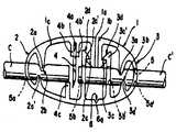
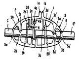
Translated fromKorean제1도, 제2도는 본 발명에 관한 절단분리기구의 실시예 1, 실시예 2를 도시하고, 각도의 (a), (b), (c)는 각각 수동조작전, 수동조작직후, 분리 상태의 각 정면도.1 and 2 show Examples 1 and 2 of the cutting separation mechanism according to the present invention, wherein angles (a), (b), and (c) are separated before manual operation, immediately after manual operation, and separated, respectively. Each front view of the condition.
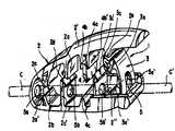
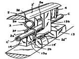
제3도는 기구의 실시예 3을 도시하고, 그의 (a)는 수동조작전의 사시도, (b)는 수동조작직후의 종단 정면도, (c)는 분리상태의 주요부를 도시한 종단 정면도.Fig. 3 shows a third embodiment of the mechanism, wherein (a) is a perspective view before manual operation, (b) is a longitudinal front view immediately after manual operation, and (c) is a longitudinal front view showing a main part in a separated state.
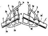
제4a, b도는 실시예 4의 각각 수동조작할때의 정면도의 분리상태의 주요부 정면도.4A and 4B are principal part front views in a separated state of the front view at the time of each manual operation of Example 4;
제5도는 실시예 5의 사시도.5 is a perspective view of a fifth embodiment.
제6도는 실시예 6의 분해 정면도.6 is an exploded front view of the sixth embodiment;
제7a, b도는 실시예 7의 각각 수동조작할때의 정면도와, 주요부를 도시한 사시도.7A and 7B are a front view and a perspective view showing main parts in each manual operation of the seventh embodiment;
제8a, b도는 실시예 8의 각각 수동조작전, 수동조작 직후의 정면도.8A and 8B are front views respectively before the manual operation and immediately after the manual operation of the eighth embodiment;
제9a, b도는 실시예 9의 각각 수동조작전, 수동조작시의 주요부를 도시한 정면도.9A and 9B are front views each showing the principal part during manual operation and manual operation of Example 9 respectively;
제10도는 동기구를 인공투석에 사용한 상태의 설명도.10 is an explanatory diagram of a state where a synchronous sphere is used for artificial dialysis.
제11도는 종래의 유로용 튜우브 절단 수단을 도시한 설명도.11 is an explanatory diagram showing a conventional channel tubing cutting means.
* 도면의 주요부분에 대한 부호의 설명* Explanation of symbols for main parts of the drawings
1 : 악지용본체 2 : 제1부1: Body for bad music 2: Part 1
2a : 제1상측돌기 2a' : 제1하측돌기2a: first upper protrusion 2a ': first lower protrusion
2b : 제1지류부 2d : 제1지지부2b:
3 : 제2부 3a : 제2상측돌기3:
3a' : 제2하측돌기 3b : 제2지류부3a ': second
3d : 제2지지부 4 : 커터3d: second support part 4: cutter
6 : 절단분리부 C : 유로용 튜우브6: cutting separator C: tube for flow path
본 발명은 혈액, 각종의 화학용액이나 가스등을 흐르게 하고 있는 유로용 튜우브에 부설하여 두고 재해 발생시에는 이것을 수동조작하는 것만으로 이 튜우브를 상기 혈액등이 유실하여 버리는 일이 없도록 절단분리해서, 예컨대 인공투석(人工透析)중의 입원환자라도 자력으로 긴급대피가 될수 있도록 하든지, 또 위험한 약품의 격리등 적절한 조치를 신속하게 할 수 있도록 한 혈액등의 유로용 튜우브 절단분리기구에 관한 것이다.The present invention is provided in a flow path tube through which blood, various chemical solutions or gases flow, and in the event of a disaster, the tub is cut and separated so that the blood is not lost by simply manipulating it. For example, the present invention relates to a tubing cutting and separating mechanism for blood, etc., which allows an inpatient in artificial dialysis to be able to evacuate on his own or to promptly take appropriate measures such as quarantine of dangerous chemicals.
이미 알려진 바와같이 신장환자는 자기의 혈액중에 있어서의 독소를 정화하기 위해, 3일에 1회는 5 내지 8시간에 걸쳐서 인공투석의 치료를 받지 않으면 안되지만, 여기에서는 제10도에 도시한대로 환자의 인체(A)와 인공신장(B)을 혈액등의 유로용 튜우브(C)에 의해 연결하는 것으로, 혈액회로를 폐성하는 것이고, 이때 상기 튜우브(C)의 연결단부(C',C')는 환자의 양팔에 빠지는 일이 없도록 부착되어 있기 때문에 환자는 누운상태로 자유롭게 움직일 수도 없다.As is already known, a kidney patient must be treated with artificial dialysis over five to eight hours once every three days to purify the toxins in his blood, but here, as shown in FIG. By connecting the human body (A) and the artificial kidney (B) by a flow path tube (C), such as blood, to close the blood circuit, and at this time, the connection ends (C ', C') of the tube (C) ) Is attached to the patient's arms so that the patient cannot move freely while lying down.
따라서, 이와같은 경우에 지진, 화재등의 재해가 발생했다고 할때, 환자는 자력으로 탈출하는 것이 불가능하고, 이때문에 종래는 아무리하여도 간호원등에 의해 제11도와 같이 유로용 튜우브(C)를 클립(D,D')에 의해 협지하고, 이것에 의해 혈류를 저지한후, 가위(E)에 의해 클립(D,D') 사이의 동튜우브(C)를 절단하는 것으로서, 연결단부(C',C')를 부착한대로 환자가 탈출할 수 있도록 하지 않으면 안되었다.Therefore, in such a case, when a disaster such as an earthquake or fire occurs, the patient cannot escape on his own, and thus, conventionally, no matter how much, for example, a nurse's tube or the like can provide a tubing tube C as shown in FIG. Is pinched by the clips D and D ', the blood flow is blocked by the clips D, and the copper tube C between the clips D and D' is cut by the scissors E. C ', C') had to be able to escape the patient as attached.
본 발명은 상기의 종래예에 감안하여 상기의 인공투석과 같은 경우에는 미리 환자 자신이 수동조작할 수 있는 위치에 있어, 해당 유로용 튜우브(C)에, 제10도와 같이 적절한 구성을 가진 절단분리기구(F,F')를 부설하여 두고 재해발생시에는 환자자신이 각각 손을 사용해서, 이것을 꽉 쥔다고 하는 간단한 조작만으로 2개소에서 혈류를 저지함과 동시에, 해당 지혈상태를 지지시켜 해당 2개소의 사이에서 동 튜우브를 절단하고, 또한 이 절단분리기구(F,F')를 각각 2등분 가능하게 구성함으로써, 환자가 자력에 의해 간단 신속하게 혈액을 방산하는 일 없이 대피할 수 있도록 하는 것이 그 목적이고, 물론 이것을 이화학적 또는 공업적인 유로용 튜우브에 채택하면, 재해 발생시에 2차 재해의 발생원인으로 되는 것 같은 약품에 대한 응급조치도 정확하게 행할 수 있게 된다.In the case of the above-described artificial dialysis, the present invention is in a position where the patient himself can be manually operated in advance in the case of the above-mentioned artificial dialysis, and the cutting having an appropriate configuration as shown in FIG. Separate mechanisms (F, F ') are installed, and in the event of a disaster, the patient himself uses his or her hand to hold the blood tightly in two places, stopping blood flow and supporting the state of hemostasis. The tube is cut between the points, and the cutting separation mechanisms (F, F ') can be divided into two parts so that the patient can evacuate the blood without discharging the blood simply and quickly. Its purpose is, of course, to adopt a physicochemical or industrial tubing for the first time, and it is possible to accurately perform first aid measures for drugs that are likely to cause secondary disasters in the event of a disaster. It is possible.
본 발명은 상기의 목적을 달성하기 위해 혈액등의 유로용 튜우브가 끼워 통할 수 있게 형성된 악지용 본체는 절단분리부에서 분리 가능하게 한 일측의 제1부와 다른 측의 제2부로 이루어지고, 제1부와 제2부에는 악지용본체를 누르는 것으로서, 상기의 유로용 튜우브를 협압해서 흐름을 저지 가능하게한 각각 제1, 제2지류부와 해당지류상태를 지지시키는 각 제1, 제2지지부를 설치함과 동시에, 제1부 또는 제2부에는 그의 지류부 보다도 타부 가까이에 상기 누름에 의해 해당 튜우브를 절단하는 커터가 배설되어 있는 것을 특징으로 하는 혈액등의 유로용 튜우브 절단분리기구를 제공하려는 것이다.In order to achieve the above object, the present invention includes a main body for a bad finger formed so that a tubing tube for blood, such as blood, can be inserted into a first part on one side and a second part on the other side, which are detachable from the cutting separator. The first and second sections are pressed against the main body for holding the first and second sections, and the first and second branch sections and respective first and second sections supporting the state of the branch section can be supported by pressing the flow channel tubing to stop the flow. At the same time, the supporter is provided with a cutter for cutting the tubing by pressing the first part or the second part closer to the other part than the branch part thereof. To provide a separation mechanism.
본 발명에 관한 절단분리기구는 미리 유로용 튜우브를 끼워 통하도록해서, 여기에 부착되어 있기 때문에 환자들이 기구를 꽉 잡는다든가, 부수게 하도록 하면, 악지용본체가 변형하는 것으로서 그의 제1부, 제2부에 있어서의 제1지류부, 제2지류부가 상기 튜우브(C)의 혈압에 의해 혈류등을 멈추게 함과 동시에 이 지류상태가 해당 변형에 의해 걸림상태로 되는 제1지지부, 제2지지부에 의해 각각 지지되고, 그위에 이 지류상태로 커터가 제1, 제2지류부 사이에서 유로용 튜우브를 절단하게 된다. 또한 제1부, 제2부란, 절단분리부를 절곡하든지, 상기 커터에 의해 절단하든지, 또 뗀다고 하는 간단한 조작으로 분리할 수가 있고, 이것에 의해 인공투석중의 환자의 경우라도 제1부 또는 제2부가 부착된 해당튜우브(C)의 연결단부(C', C')를 부착한대로 자력 탈출이 가능하게 된다.Since the cutting separation mechanism according to the present invention allows the flow passage tubing to be inserted in advance and is attached thereto, when the patient grips or crushes the mechanism, the body for the jaw is deformed as its first part, The first support part and the second feeder part and the second feeder part in the second part stop the blood flow and the like by the blood pressure of the tub C and at the same time, the first support part and the second jammed state are caught by the corresponding deformation. Supported by the supporting portion, respectively, the cutter cuts the flow path tubing between the first and second feeder portions in this feeder state. The first and second sections can be separated by a simple operation such as bending the cutting separator, cutting by the cutter, or by squeezing. Thus, even in the case of a patient during artificial dialysis, the first or second section can be separated. The magnetic force escape is possible by attaching the connection ends C 'and C' of the corresponding tube C having two parts attached thereto.
본 발명은 우선, 제1도 내지 제3도에 도시한 실시예에 의해 상세히 기술하면, 합성수지등에 의해 탄성적으로 변형 자유롭게 되도록 형성한 악지용본체(1)는, 도면중 좌측의 제1부(2)와 우측의 제2부(3)를 구비하고, 제1도, 제2도의 실시예로는 해당양부(2,3)가 일체로 그리고 제3도에서는 별체로 형성한 것이 도시되어 있다.First, the present invention will be described in detail with reference to the embodiments shown in FIGS. 1 to 3, wherein the body 1 for the gripper formed so as to be elastically deformable by a synthetic resin or the like has a first portion (left) in the drawing ( 2) and the
여기서, 제2도의 상기 본체(1)는 끝단부(1a, 1b)를 대향시켜서 환상으로 형성한 변형자유로운 외주 테체(1c)를 가지고, 제1부(2)와 제2부(3)에는 해당테체(1c)에서 상하 배치로 또한 약간만 좌우로 비키어 돌설한 제1상측돌기(2a), 제2상측돌기(3a)와 제1하측돌기(2a'), 제2하측돌기(3a')의 설치에 의해 각각 제1지류부(2b), 제2지류부(3b)가 구성되어 있음과 동시에 제1상측 클릭편(2c), 제2상측클릭편(3c)과 제1하측클릭편(2c'), 제2하측클릭편(3c')과의 설치에 의해, 후술의 수동조작에 의해 해당 각 클릭편이 서로 걸림 자유로운 제1지지부(2d), 제2지지부(3d)가 형성되어 있다.Here, the main body 1 of FIG. 2 has a deformable outer periphery te body 1c formed in an annular shape by opposing the end portions 1a and 1b, and corresponding to the
그리고, 또한 도시예에서는 제1부(2)에 있어, 그의 외주테체(1c)에서 커터(4)가 하향으로 돌출설치되어 있고, 4a는 동외주 테체(1c)에서 돌조(4b, 4b')를 돌출설치하는 것으로서 형성된 커터(4)의 끼워붙임 홈을 도시하며, 여기서 해당 커터(4)는 제1부(2)의 제1지류부(2b) 보다도 제2부 가까이에 설치되어 있다.In addition, in the example of illustration, in the
도면중 5는, 상기의 고무등에 의해 형성된 유로용 튜우브(C)를 끼워 통하기 위한 연통공이고 제1도와 제2도의 실시예에 있어서는 외주테체(1c)의 하위측 좌우로 돌출설치한 제1, 제2의 외측공(5a, 5a')과 제1하측클릭편(2c'), 제2하측클릭편(3c')에 뚫어 설치한 제1, 제2내측공(5b, 5b')에 의해 구성되어 있다.5 is a communication hole through which the flow channel tubing C formed by the said rubber | gum etc. is made to pass, and in the Example of FIG. 1 and FIG. 2, the 1st which protruded in the lower side left and right of the outer periphery 1c is shown. In the first and second
여기서 제1도의 실시예에서는 제1부(2)에 있어 커터(4)가 제1지류부(2b)와 우단측의 제1지지부(2d)와의 사이에 있어 아래로 돌출되어 있는 것에 대해 제2도의 예시의 것에 있어서는 해당커터(4)가 최우단에 형성되어 있고, 제1도의 4c는 후술과 같이 커터(4)에 의해 유로용 튜우브(C)를 절단하기 쉽도록 외주테체(1c)에서 상부로 돌출설치한 튜우브받이 돌출부를 도시하고 있다.Here, in the embodiment of FIG. 1, the cutter 4 is projected downward in the
또한 본 발명에서는 악지용본체(1)가, 제1부(2)와 제2부(3)로 분리 가능하게 되도록 절단분리부(6)가 형성되어 있다.Further, in the present invention, the
제1도의 절단분리부(6)는 상기의 제1하측클릭편(2c')과 제2하측클릭편(3c')과의 사이에 있고, 외주 테체(1c)에 내측에서 절단면을 넣으므로서 얻어지는 절손용 얇은 두께(6a)에 의해 형성되어 있고, 이것은 한손 조작으로도 절곡 조작할 수가 있는 것이다.The
이것에 대해 제2도의 절단분리부(6)는 상기한 커터(4)의 바로 아래위치에 있어 외주 테체(1c)에 설치한 절단용 얇은 두께(6b)에 의해 형성되고 이것은 후술과 같이 악지용본체(1)에 수동조작에 의한 악지력을 가해서 커터(4)에 의해 유로용 튜우브(c)를 절단한 후, 동커터(4)로 절단되고, 이것에 의해 양부(2, 3)가 분리되는 것으로, 도시예에서는 외주 테체(1c)의 하부 중앙에서 돌출한 입상각부(6', 6')사이에 가로 방향으로 설치되어 있다.On the other hand, the
한편 제3도에 도시한 실시예에서는 상기와 같이 제2부(3)가 제2지류부(3b), 제2지지부(3d)를 구비해서 별체로 형성되고, 이것이 제1부(2)의 U자상으로한 외주하우징(2')의 하위 우단에 설치된 수납 오목소(2")에 있어, 동하우징(2')의 상위 우단과의 사이에 이탈 자유롭도록 수납되어 있다.On the other hand, in the embodiment shown in FIG. 3, as described above, the
따라서 본 실시예에 있어서의 절단분리부(6)는 전예와 같이 얇은 두께에 의함이 없이, 별체인 해당 제2부(3)와, 제1부(2)와의 맞닿는 구조에 의해 형성되어 있는 것으로 된다. 여기서 도면중 2e는 해당 별체인 제2부(3)의 제2하측클릭편(3c')에 걸리게 되는 제2상측클릭편(3c)을 아래로 누르는 누름용 돌출부이고, 또 본예에서는 상기 제2내측공(5b'), 제2외측공(5a')이, 동 별체로서의 제2부(3)에 있어, 각각 상기 제2하측 클릭편(3c') 제2상측 클릭편(5c)에 뚫어 설치되어 있다.Therefore, the
그래서 이들의 실시예에 의한 절단분리기구를 사용하는데는 도시와 같이 유로용 튜우브(c)를 제1, 제2외측공(5a, 5a') 그리고 제1, 제2내측공(5b, 5b')에 의한 연통공(5)에 삽통해서 적절한 위치 즉 상기 인공투석의 경우이면 제10도에 대해 상기한 바와같이 수동조작 가능한 개소에 부착설치하여 둔다.Thus, in order to use the cutting separation mechanism according to these embodiments, as shown in the drawing, the tubing c for the flow path is divided into the first and second
지금 지진, 화재등의 재해가 발생했을때는 해당환자 자신이 각각 좌우의 각손으로 제1, 제2도에서는 악지용본체(1)의 외주테체(1c)를 제3도의 것에서는 제1부(2)의 외주하우징(2')을 악지하는 등해서, 이것을 잡아 부수도록 하면 좋고, 이것에 의해 제1도 내지 제3b도에 도시된 대로 제1, 제2상측돌기(2a, 3a)의 제1, 제2하측돌기(2a', 3a')의 근접에 의해 제1지류부(2b), 제2지류부(3b)가 유로용 튜우브(c)를 눌러 부수고 흐름을 멈추게 하고, 이때 제1, 제2상측 클릭편(2c, 3c)과 제1, 제2하측클릭편(2c', 3c')이 각각 걸리게 함에 이르러, 해당지류 상태가 지지됨과 동시에, 상기 커터(4)가 동상 튜우브(c)를 절단하게 된다. 그래서 인공투석을 받고 있는 해당환자는 제1도의 경우 또한 외주테체(1c)를 절곡하도록해서, 상기 절손용 얇은 두께(6a)를 파단하면 좋고, 이것으로 제1부(2)와 제2부(3)가 동도면(c)와 같이 분리되게 되고, 이것에 의해 동환자는 분리된 제2부(3)가 부착된 대로의 연결단부(c')를 설치한 상태로 대피할 수가 있다. 또 제2도의 경우이면, 상기와 같은 환자에 의한 절곡조작을 필요로 하지 않으며, 그의 전단에 있어서의 악지 조작만으로 커터(4)가 절단용 얇은 두께(6b)를 절단하여 버리기 때문에 보다 신속하게 제1부(2)와 제2부(3)와의 분리가 가능하게 된다.When a disaster such as an earthquake or fire has occurred, the patient himself has his or her left and right hands, respectively, in Figures 1 and 2, and the outer periphery 1c of the body for evil music 1, and in Figure 3, Part 1 (2). The outer periphery housing 2 'of the head) may be gripped and crushed, so that the first and the second
또한 제3도의 실시예에 의하면, 동상 악지조작후, 해당 악지를 해제하고, 이어서 환자가 동도면(c)의 화살표(G)방향으로 연결단부(c')를 잡아 당기는 것 만으로 별체의 제2부(3)는 제1부(2)에서 꺼내져, 이것 또한 신속한 양부(2, 3)의 분리가 되게 된다.In addition, according to the embodiment of Fig. 3, after the frostbite grip operation, the gripper is released, and the patient then pulls the connecting end c 'in the direction of the arrow G of the same drawing plane c, and then separates it. The
다음에 본 발명을 제4도 내지 제7도의 실시예에 대해서, 더욱 설명 도시하면, 우선 제4도의 경우에 있어서는 제3도의 실시예와 같이 제2부(3)가 제1부(2)하고는 별체로 형성되어 있고, 그의 배치가 제1부(2)의 U자상으로한 외주하우징(2')에 있어, 그의 하위 우측에 존재하고 있는 점에서 동일 구성이지만, 해당 제2부(3)가, 탄성판을 대략 C자상으로 곡성되어, 또한 평상시에는 그의 탄력에 의해 환상으로 폐지하고 있는 것이 제1의 상위점으로 되어 있다.Next, the present invention will be described in more detail with reference to the embodiments of FIGS. 4 through 7, firstly, in the case of FIG. 4, the
즉, 해당 제2부(3)는 평상시에 있어, 서로 그의 탄력에 의해 맞닿는 제2상측돌기(3a)와 제2하측돌기(3a')에 의해, 제2지류부(3b)가 형성되어 있음과 동시에 해당 제2부(3)의 탄성 복원력원으로 되어 있는 구부러진 부분이 제2지지부(3d)의 역활을 이루도록 구성되어 있다.That is, the
또한 제2의 상위점은 그의 절단분리부(6)의 구성이고, 앞에 설명한 3도의 실시예에서는 제2부(3)가 제1부(2)의 수납 오목부(2")에 절결자유롭도록 맞닿고 있는 구조로 되어 있는데 대해, 본 실시예에서는 상기 탄성판의 구부러짐에 의해 제2부(3)의 제2지류부(3b)가 열리도록, 그의 탄력에 저항해서 떨어진 상기의 제2상측돌기(3a)와 제2하측돌기(3a')를 각각 제1부(2)의 외주하우징(2')에 있어, 그의 하위중앙에서 돌출 설치한 절단분리용 돌기부(7)의 상단부(7a)의 하단부(7b)에 각각 이탈 자유롭도록 끼워 장착하여 걸리게 함으로써 절단분리부(6)가 형성되어 있다.In addition, the second difference is the configuration of the cutting
그리고 상기 외주하우징(2')의 상위 우측에서는 제2부(3)의 제2상측돌기(3a)에 있어, 그의 상측 절반편부(8)를 누르기 자유로운 누름용돌조(2e')가 돌출 설치되어, 또 본예에서는 이 제2부(3)에 앞서 설명한 제2외측공(5a')이 뚫어 설치되어 있는 것이나, 제2내측공(5b')에 대응하는 것이 아니고, 상기의 절단분리용 돌기부(7)에 제1최내측공(5c)이 뚫어 설치되어 있다.On the upper right side of the outer housing 2 ', the pressing protrusion 2e' freely presses on the upper half side portion 8 of the second
따라서 해당 실시예에서는 상기 연통공(5)에 유로용 튜우브(c)를 끼워 통한 상태로서 제4a도와 같이 외주하우징(2')을 악지하면 상기의 누름용돌조(2e')가 제2상측돌기(3a)의 상측 절반편부(8)를 누르고 이것에 의해 해당 제2상측돌기(3a)와 제2하측돌기(3a')가 절단분리용 돌기부(7)의 각각 상단부(7a), 하단부(7b)에서 이탈한다.Therefore, in this embodiment, when the outer circumferential housing 2 'is gripped as shown in FIG. 4A through the channel tubing c inserted into the
이 결과 해당 제2부(3)는, 그 자체를 구비하고 있는 탄성 복원력에 의해, 제4b도 와 같이 평상 상태로 복귀하고, 이것에서 제2상측돌기(3a)와 제2하측돌기(3a')와의 사이에 유로용 튜우브(c)가 끼워 부착됨과 동시에, 이 지류상태는 지지되게 되고, 그 위에 제3도와 같은 구성으로 설치되어 있는 커터(4)가 동상 튜우브(c)를 절단하기 때문에, 환자들은 제1부(2)에서 분리된 제2부(3)가 부착된대로의 연결단부(c')를 설치한 상태로 대피할 수가 있게 된다.As a result, the said
다음에 제5도의 실시예에서는 제4도와 같이 제2부(3)만을 탄성판이 구부러지게 형성해서 별체로서 있을 뿐만 아니라, 제1부(2)가 외주하우징(2')과 여기에 걸거나 벗김이 자유롭도록 계장한 탄성지류편(2"')에 의해 구성되어 있다.Next, in the embodiment of FIG. 5, as shown in FIG. 4, only the
즉, 해당 제1부(2)의 외주하우징(2')에는 그의 상위측 중앙에 제4도의 경우와 같이 커터(4)가 하향으로 돌출설치되어 있을 뿐만 아니라, 하위측에 있어, 상기 커터(4)의 좌측에는 제4도에 대해 상세히 기재한 절단분리용 돌기부(7)와 대응시켜서 대략 동형의 지류돌기부(9)를 돌설하고, 그의 상단부(9a)와 하단부(9b)에 제2부(3)와 대략 동형으로 되도록 탄성판을 구부린 상기 탄성지류편(2"')의 제1상측돌기(2a)와 제1하측돌기(2a')를 걸어둔다.That is, in the outer circumferential housing 2 'of the
그리고, 이 탄성지류편(2"')은, 평상시 상기의 제1상측, 제1하측돌기(2a, 2a')가 탄성접촉 상태로 되도록 구부리게 되고, 따라서 후술하는 바와같이 탄성지류편(2"')이 지류용돌기부(9)에서 빠졌을때는 해당 탄성지류편(2"')의 구부러진 부분이 제1지지부(2d)의 역활을 달성하고, 이 구부러진 부분에 의한 탄력에 의해, 제1상측, 제1하측돌기(2a, 2a')에 의한 제1지류부(2b)의 폐지상태가 지지되도록 되어 있다.The
또한, 외주하우징(2')의 상위측에는 제4도의 경우와 같이 누름용돌조(2e')가 돌출설치될 뿐만 아니라, 커터(4)의 반대방향에도 누름용 돌조(2e")가 돌출설치되어 있어, 제4도에 대해 설명도시한 바와같이 외주하우징(2')을 잡아 부수도록 조작함으로서, 제2부(3)가 절단분리용 돌기부(7)에서 빠질뿐 아니라, 탄성지류편(2"')로 지류용 돌기부(9)에서 빠져서 유로용 튜우브(c)가 제1상측, 제1하측돌기(2a, 2a')에 의해 협착되고, 지류상태가 지지되게 된다. 또 여기서 해당실시예에서는 앞에 설명한 연통공(5)에 있어서의 제1내측공(5b)이 상기 탄성지류편(2"')의 구부러진 부분에 뚫어 설치되어 있고, 그위에 상기의 지류용 돌기부(9)에 제1중위 내측공(5d)이 관통되어 있음과 동시에 외주하우징(2')의 하위측에 있어, 그의 자유단측에는 유로용 튜우브(c)를 걸어 끼워 놓기 위한 절단면홈(10)이 설치되어 있다.In addition, as shown in FIG. 4, the pressing protrusion 2e 'is protrudingly installed on the upper side of the outer housing 2', and the pressing protrusion 2e "is protrudingly installed in the opposite direction of the cutter 4, too. As shown in FIG. 4, the outer housing 2 'is operated by grasping and breaking, so that the
여기서 다음의 제6도에 도시되어 있는 실시예는 상기 제5도의 것과 큰차는 없고, 단지 제1부(2)를 구성하고 있는 외주하우징(2')인 것이 ㄷ자상으로 일체로 구성되어 있는 앞 실시예하고 달라서 하부하우징(2f)과 상부하우징(2f')으로 이루어지고 있으며, 상부하우징(2f')에 전기와 같이 커터(4), 제1, 제2누름용 돌조(2e", 2e')가 설치되어 있을 뿐만 아니라, 상기 커터(4)의 전후 양측에 안내길이홈(11)이 종설되어 있어, 이에 하부하우징(2f)의 전후 벽면에서 돌출 설치한 축간(12)이 끼워 넣어져 있고, 이것에 의해 상기한 대로, 이 외주하우징(2')을 잡아 부수도록 조작하면, 양하우징(2f, 2f')의 이간거리가 단축되어서, 제5도의 경우와 거의 같은 사용모양의 지류, 분리의 목적을 달성할 수 있는 것이다.Here, the embodiment shown in FIG. 6, which is the same as that of FIG. 5, is not substantially different from that of FIG. 5, and that the outer housing 2 'constituting the
또, 제7도에 의해 도시되고 있는 실시예로서는 제4도에 의해 구현되고 있는 본 발명과 근사하고 있으나, 양자의 상위점은, 제2부(3)와 절단분리부(6)의 구성에 있다.In addition, although the embodiment shown by FIG. 7 is close to the present invention implemented by FIG. 4, the difference between the two is in the configuration of the
즉, 제2부(3)가 탄성조의 곡성에 의해 별체로 형성되어, 그의 곡성에 의한 형상도 제4도에서는 C자상인데 반해, 본 실시예에서는 상위 환상교차부(3e)와 하위 협지부(3f)에 의해 대략
다음에 절단분리부(6)를 구성하기 위해, 본 실시예에서는 외주하우징(2')의 상위측에서 L자상의 분리용 발취간(13)을 돌출 설치하고, 그의 하단측인 가로향부(13a)를 제2부(3)의 하위 협지부(3f)에 대해 이것을 단력에 저항해서 열도록 하고, 제1좌측돌기(2a")와 제1우측돌기(2a"")와의 사이에 협입하여 둠과 동시에, 이때 하위 협지부(3f)의 양하단을 외주하우징(2')의 하단측에서 돌출설치한 재치돌부(14, 14')에 과재하고, 제7b도와 같은 상태로 하고, 그위에 이때 상기 분리용 발취간(13)의 세로향부(13b)에는 연통공(5)인 제1최내측공(5e)이 세로 길이로 돌출설치되어 있다. 따라서, 사용에 있어 다른예와 같이 외주하우징(2')을 잡아 부수도록 했을때는 분리용 발취간(13)이 재치돌부(14, 14') 사이에 진입하강해서 나가게 되고, 마침내 하위협지부(3f)에서 하향으로 발출하게 되는 것으로서, 유로용 튜우브(c)가 제1좌측과 제1우측돌기(2a", 2a"')에 의해 협착된 지류 상태를 지지하게 되는 것이기 때문에, 본 실시예에 있어서의 절단분리부(6)라는 것은 제2부(3)와, 여기에 이탈자유롭도록 협착되는 분리용 발취간(13)과의 맞닿음에 의해 구성되어 있는 것으로 된다.Next, in order to form the cutting
또한 제8도에 도시한 실시예에 있어, 지금까지 설명 도시한 것과 특히 상위하고 있는 곳은 제1부(2)에 있어서의 제1지류부(2b)와 제2부(3) 제2지류부(3b)의 구성이다.In addition, in the embodiment shown in FIG. 8, the
즉, 해당 제8도에 있어서의 제1, 제2지류부(2b, 3b)의 각각 제1상측돌기(2a)와 제2상측돌기(3a)에 대해서는 지금까지의 실시예와 같게 변형하기 어려운 것으로 되어 있으나, 제1하측돌기(2a')와 제2하측돌기(3a')와는 누르면 해당 누름 방향과는 역행해서 만곡 변형 자유롭도록 해당 도시예에서는 각각 제1부(2)와 제2부(3)에서 가로방향으로 제1, 제2탄성아암(2f, 3f)을 연출하고, 그의 자유단에 상향으로 융기부를 돌출설치시키도록 되어 있다. 따라서, 상기 구성의 것에 의하면, 유로용 튜우브(c)의 두께 치수가 비교적 작은 경우에, 상기와 같이 커터(4)에 의해, 해당 튜우브(c) 그리고 절단분리부(6)의 절단용 얇은 두께(6b)를 확실하고 절단분리할 수 있는 것은 물론, 만약 제법 유로용 튜우브(c)의 두께가 큰 경우라 하여도, 해당 튜우브(c)를 제1, 제2상측돌기(2a, 3a)가 눌렀을때, 제1, 제2하측돌기(2a', 3a')의 제1, 제2탄성아암(2g, 3g)이 하향으로 만곡가능하게 되기 때문에, 제1, 제2지름부(2b, 3b)의 지류가 행하여짐과 동시에, 제1, 제2지지부(2d, 3d)의 지지상태도 확실하게 얻어져, 커터(4)에 의한 절단동작도 완결할 수 있게 된다.That is, the first upper projections 2a and the second
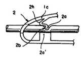
여기서 제9도에 도시한 것은 제8도에 있어서의 제1, 제2지류부(2b, 3b)의 구성과는 반대로 제1하측돌기(2a')가 변형하기 어려운 형상으로 되어 있어서, 제1상측돌기(2a)가 동도면(a)의 신장상태에서 동도면(b)의 축소상태로 변형 자유롭도록 형성되어 있다.In FIG. 9, the first lower protrusion 2a 'is hardly deformed as opposed to the configuration of the first and
즉 제1상측돌기(2a)에는 중간부위에 굴곡탄성부(2h)가 구부러져 있고, 상기와 같이 대경의 유로용 튜우브(c)가 사용되는 경우에는 이 굴곡탄성부(2h)가 굴곡하는 것으로 축소상태로 될 수 있도록 되어 있다.In other words, when the flexible
또 제8도의 실시예에서는 제1부(2)와 제2부(3)가 일체로 형성되어 있으나, 사용에 있어서는 제1부(2)를 꽉쥠으로서, 제2부(3)를 제1부(2)에 의해 협압하는 구성으로 되어 있고, 3e가 제2부(3)에 있어 돌출설치된 누름수승용돌조로, 여기에 제1부(2)가 누를시에 맞닿는다. 또 거리(4)의 고정수단은 외주테체(1c)에서 돌출설치된 설치아암(4d)에서 돌출설치된 돌기(4e)를 커터(4)의 설치공에 끼워 맞추고, 해당돌기(4e)의 열코오킹에 의한 것이고, 1d, 1d'는 외주테체(1c)의 악지개소에 설치한 논슬립부를 도시하고 있다.In addition, although the
또 상기 도시예에서는 제1, 제2상측돌기(2a, 3a)와 제1, 제2하측돌기(2a', 2a')에 있어,그의 한쪽 측만을 탄성 변형 자유롭게 해서, 스프링 액션을 활용할 수 있는 구성으로 하였으나, 물론 상하 양측에 거쳐서 모든 돌기에 스프링액션을 가져오게 하는 것도 가능하다.In the above-described example, in the first and second
상기 구성의 실시예에 의할 때는 기술한대로 유로용 튜우브(C)의 두께 치수에 흩어짐이 있어도, 이것을 충분히 지류상태로 하는 것이 가능하게 되기 때문에, 한개의 절단분리기구에 의해 각종의 유로용 튜우브에 대한 범용성이 얻어지고, 또한 일정치수의 유로용 튜우브에 사용하는 경우에 있어서도, 본 발명에 관한 절단분리기구의 제작에 있어, 성형시의 치수 수축등의 범위를 넓게 취할 수가 있게 되서, 생산관리가 용이하게 되고, 또 그의 금형에 있어서도, 그다지 높은 정밀도를 요구하지 않게 된다.According to the embodiment of the above configuration, even if there is scattering in the thickness dimension of the channel tubing C as described above, it is possible to make this sufficiently feeder state, so that various flow path tubing can be made by one cutting separation mechanism. The versatility of the groove can be obtained, and even in the case of using the tube for a constant size flow path tubing, in the manufacture of the cutting separation mechanism according to the present invention, it is possible to take a wide range of dimensional shrinkage during molding, Production management becomes easy, and also the mold does not require very high precision.
본 발명은 상기한 바와 같이 해서 구성되는 것이기 때문에, 이것을 유로용 튜우브에 끼워 통하게 부설하여 두는 것만으로, 환자나 작업자가 극히 간단한 수동조작에 의해 해당 튜우브의 지류와 절단 및 절단분리기구 자체의 분리를 신속하게 행할 수가 있고, 그 결과 긴급을 요하는 재해 발생에 있어서도 간호원등 다른사람의 손을 번거롭게 하는 일 없이, 자력에 의해 혈액이든가, 액액을 방산하는 일 없이 대피하든지, 위험물의 간격을 행할 수가 있다. 또 본 발명은 합성수지에 의해 성형되는 것이기 때문에 동맥용, 정맥용으로서 색별 성형하면 부착시 혹은 재사용시에 있어서 한층 유효한 조치를 취할 수가 있다.Since the present invention is constituted as described above, it is only to be placed in the flow path tubing, so that the patient and the operator can make the branch of the tub and the cutting and cutting and separating mechanism itself by extremely simple manual operation. Separation can be carried out quickly, and as a result, even when an emergency disaster occurs, emergency personnel do not bother the hands of others, such as blood, or evacuate without discharging liquid or discharging liquids. I can do it. In addition, since the present invention is molded by a synthetic resin, color-coated molding for arteries and veins can provide more effective measures at the time of attachment or reuse.
Claims (2)
Translated fromKoreanPriority Applications (1)
| Application Number | Priority Date | Filing Date | Title |
|---|---|---|---|
| KR1019870003011AKR910000030B1 (en) | 1987-03-31 | 1987-03-31 | Tube cutting and separating implement for conduit of blood or the like |
Applications Claiming Priority (1)
| Application Number | Priority Date | Filing Date | Title |
|---|---|---|---|
| KR1019870003011AKR910000030B1 (en) | 1987-03-31 | 1987-03-31 | Tube cutting and separating implement for conduit of blood or the like |
Publications (2)
| Publication Number | Publication Date |
|---|---|
| KR880010783A KR880010783A (en) | 1988-10-24 |
| KR910000030B1true KR910000030B1 (en) | 1991-01-19 |
Family
ID=19260421
Family Applications (1)
| Application Number | Title | Priority Date | Filing Date |
|---|---|---|---|
| KR1019870003011AExpiredKR910000030B1 (en) | 1987-03-31 | 1987-03-31 | Tube cutting and separating implement for conduit of blood or the like |
Country Status (1)
| Country | Link |
|---|---|
| KR (1) | KR910000030B1 (en) |
- 1987
- 1987-03-31KRKR1019870003011Apatent/KR910000030B1/ennot_activeExpired
Also Published As
| Publication number | Publication date |
|---|---|
| KR880010783A (en) | 1988-10-24 |
Similar Documents
| Publication | Publication Date | Title |
|---|---|---|
| US5797922A (en) | Umbilical cord clamping device | |
| US3204636A (en) | Funis clamp | |
| JP5681644B2 (en) | Apparatus and method for occluding a flexible tube | |
| US5270003A (en) | Blood sampling system | |
| KR960010978B1 (en) | Lancet device | |
| US4676476A (en) | Shut-off and severing device | |
| EP0066693B1 (en) | Sterile fluid conduit connector | |
| US6348057B1 (en) | Umbilical cord clamp and cutter | |
| CA2178628A1 (en) | A catheter or cannula system | |
| EP1231863A1 (en) | Surgical instrument for clamping and cutting an umbilical cord | |
| KR20010078691A (en) | Compressible structure clamping and cutting | |
| WO1984000293A1 (en) | Attachement device for medical fluids bag | |
| EP1163919A2 (en) | Protection device for medical needles | |
| US3983604A (en) | Identification band clip | |
| KR910000030B1 (en) | Tube cutting and separating implement for conduit of blood or the like | |
| US8443824B2 (en) | Fluid flow controller | |
| JPH0259742B2 (en) | ||
| JPH0518588B2 (en) | ||
| JPH1028731A (en) | Cutter for medical tube | |
| JP3853014B2 (en) | Medical tube disconnector | |
| CN110650699A (en) | Circumcision device | |
| JP3122020U (en) | Branch pipe with clamp and medical device | |
| JPH025794Y2 (en) | ||
| JPH0518587B2 (en) | ||
| CN213552185U (en) | Automatic safety spring type internal fistula puncture needle |
Legal Events
| Date | Code | Title | Description |
|---|---|---|---|
| PA0109 | Patent application | St.27 status event code:A-0-1-A10-A12-nap-PA0109 | |
| R17-X000 | Change to representative recorded | St.27 status event code:A-3-3-R10-R17-oth-X000 | |
| P11-X000 | Amendment of application requested | St.27 status event code:A-2-2-P10-P11-nap-X000 | |
| P13-X000 | Application amended | St.27 status event code:A-2-2-P10-P13-nap-X000 | |
| A201 | Request for examination | ||
| PA0201 | Request for examination | St.27 status event code:A-1-2-D10-D11-exm-PA0201 | |
| PG1501 | Laying open of application | St.27 status event code:A-1-1-Q10-Q12-nap-PG1501 | |
| E902 | Notification of reason for refusal | ||
| PE0902 | Notice of grounds for rejection | St.27 status event code:A-1-2-D10-D21-exm-PE0902 | |
| T11-X000 | Administrative time limit extension requested | St.27 status event code:U-3-3-T10-T11-oth-X000 | |
| T11-X000 | Administrative time limit extension requested | St.27 status event code:U-3-3-T10-T11-oth-X000 | |
| G160 | Decision to publish patent application | ||
| PG1605 | Publication of application before grant of patent | St.27 status event code:A-2-2-Q10-Q13-nap-PG1605 | |
| E701 | Decision to grant or registration of patent right | ||
| PE0701 | Decision of registration | St.27 status event code:A-1-2-D10-D22-exm-PE0701 | |
| GRNT | Written decision to grant | ||
| PR0701 | Registration of establishment | St.27 status event code:A-2-4-F10-F11-exm-PR0701 | |
| PR1002 | Payment of registration fee | St.27 status event code:A-2-2-U10-U11-oth-PR1002 Fee payment year number:1 | |
| PR1001 | Payment of annual fee | St.27 status event code:A-4-4-U10-U11-oth-PR1001 Fee payment year number:4 | |
| PR1001 | Payment of annual fee | St.27 status event code:A-4-4-U10-U11-oth-PR1001 Fee payment year number:5 | |
| PR1001 | Payment of annual fee | St.27 status event code:A-4-4-U10-U11-oth-PR1001 Fee payment year number:6 | |
| PR1001 | Payment of annual fee | St.27 status event code:A-4-4-U10-U11-oth-PR1001 Fee payment year number:7 | |
| FPAY | Annual fee payment | Payment date:19971212 Year of fee payment:8 | |
| PR1001 | Payment of annual fee | St.27 status event code:A-4-4-U10-U11-oth-PR1001 Fee payment year number:8 | |
| LAPS | Lapse due to unpaid annual fee | ||
| PC1903 | Unpaid annual fee | St.27 status event code:A-4-4-U10-U13-oth-PC1903 Not in force date:19990120 Payment event data comment text:Termination Category : DEFAULT_OF_REGISTRATION_FEE | |
| PC1903 | Unpaid annual fee | St.27 status event code:N-4-6-H10-H13-oth-PC1903 Ip right cessation event data comment text:Termination Category : DEFAULT_OF_REGISTRATION_FEE Not in force date:19990120 | |
| P22-X000 | Classification modified | St.27 status event code:A-4-4-P10-P22-nap-X000 | |
| P22-X000 | Classification modified | St.27 status event code:A-4-4-P10-P22-nap-X000 |