Movatterモバイル変換


[0]ホーム

URL:


KR900007707B1 - Handheld condition test method of emergency phone in emergency call system - Google Patents

Handheld condition test method of emergency phone in emergency call system
Download PDF

Info

Publication number
KR900007707B1
KR900007707B1KR1019870011185AKR870011185AKR900007707B1KR 900007707 B1KR900007707 B1KR 900007707B1KR 1019870011185 AKR1019870011185 AKR 1019870011185AKR 870011185 AKR870011185 AKR 870011185AKR 900007707 B1KR900007707 B1KR 900007707B1
Authority
KR
South Korea
Prior art keywords
emergency
emergency telephone
line
handset
message
Prior art date
Legal status (The legal status is an assumption and is not a legal conclusion. Google has not performed a legal analysis and makes no representation as to the accuracy of the status listed.)
Expired
Application number
KR1019870011185A
Other languages
Korean (ko)
Other versions
KR890007539A (en
Inventor
신금호
Original Assignee
삼성전자 주식회사
안시환
Priority date (The priority date is an assumption and is not a legal conclusion. Google has not performed a legal analysis and makes no representation as to the accuracy of the date listed.)
Filing date
Publication date
Application filed by 삼성전자 주식회사, 안시환filedCritical삼성전자 주식회사
Priority to KR1019870011185ApriorityCriticalpatent/KR900007707B1/en
Publication of KR890007539ApublicationCriticalpatent/KR890007539A/en
Application grantedgrantedCritical
Publication of KR900007707B1publicationCriticalpatent/KR900007707B1/en
Expiredlegal-statusCriticalCurrent

Links

Images

Classifications

Landscapes

Abstract

Translated fromKorean

내용 없음.No content.

Description

Translated fromKorean
비상전화 시스템에서 비상전화기의 핸드상태 검사방식Hand state inspection method of emergency telephone in emergency call system

제1도는 본 발명에 따른 비상전화 시스템의 구성도.1 is a block diagram of an emergency telephone system according to the present invention.

제2도는 본 발명에 따른 제1도의 구성 부분중 제어장치.2 is a control device of the component parts of FIG. 1 according to the present invention.

제3도는 본 발명에 따른 비상전화기의 구성회로도.3 is a circuit diagram of an emergency telephone according to the present invention.

제4도는 제2도 및 제3도 등화회로도.4 is an equalization circuit diagram of FIGS. 2 and 3;

제5도는 선로에 따른 주파수 감쇄 특성도.5 is a frequency attenuation characteristic according to the line.

제6도는 제어장치의 비상전화기간의 통신을 위한 프레임 구성도6 is a frame diagram for communication of the emergency call period of the control device

제7도(a)-(g)도는 각 구성 부분간의 메시지 테이블도.7 (a)-(g) are message table diagrams between components.

제8도(a)(b)는 본 발명에 따른 핸드

Figure kpo00003
검사 흐름도.8 (a) (b) shows a hand according to the present invention
Figure kpo00003
Inspection flow chart.

본 발명은 비상전화 시스템에 관한 것으로, 특히 전원공급 라인이 배설되지 않은 장거리 통신로에 병렬로 접속된 비상전화기의 핸드

Figure kpo00004
검사방식에 관한 것이다.The present invention relates to an emergency telephone system, in particular, a hand of an emergency telephone connected in parallel to a long distance communication line without a power supply line.
Figure kpo00004
It is about the inspection method.

고속도로 또는 특정 지역에서는 통신로에 비상전화기를 설치하여 비상사태 또는 그밖의 긴급 통화를 요구하는 것과 같은 특정 사태가 발생할 경우, 장거리 떨어져 있는 관리사무소와 같은 중앙관제소와 신속한 통신을 하므로써 사태의 처리 또는 회복을 신속히 할 필요가 있게 된다. 이와같은 중앙관제소와 비상전화기간의 통신로는 비상전화기를 직렬 접속하는 방식보다는 하나의 통신로에 다수개의 비상전화기를 병렬로 접속하는 방식이 통신로의 설치나 비용면에서 유리하게 된다.In case of an emergency such as an emergency telephone on a highway or in a specific area requiring emergency calls or other emergency calls, prompt communication with a central control station such as a long-distance management office may be used to deal with or recover from the situation. You will need to do it quickly. Such a central control station and the emergency call period communication path is advantageous in terms of the installation and cost of the communication path to connect a plurality of emergency telephones in parallel to one communication path rather than the serial connection of the emergency telephone.

또한 중앙관제소에는 사설교환기가 설치되어 있고 이 사설교환기와 접속된 통신로에는 소정의 거리마다 비상전화기가 접속이 된다. 그러나 이와같은 병렬 접속 방식의 비상전화 시스템에 있어서는 비상전화기가 설치되는 위치가 사설교환기로부터 장거리로 소정 거리마다 이격하여 있는 관계로 해서 여러가지 문제점이 발생하게 된다. 즉, 비상전화기를 사용하기 위한 상황은 매우 긴박한 상황이므로 비상전화기들의 비상제어 시스템과 원격 이격되어 있어 해당 비상전화기의 핸드

Figure kpo00005
상태를 수동으로 검사하기에는 큰 어려움이 및 시간상의 낭비가 초래되며, 또한 핸드
Figure kpo00006
의 이상상태 발생시 이를 인지하지 못하면 비상전화기로서 본연의 임무를 수행하지 못하는 문제점이 있었다.In addition, a private exchange is installed at the central control station, and emergency telephones are connected to the communication path connected to the private exchange at predetermined distances. However, in such a parallel connection type emergency telephone system, various problems arise due to the fact that the position where the emergency telephone is installed is spaced at a predetermined distance from the private switching center for a long distance. That is, the situation for using the emergency phone is very urgent, so it is remote from the emergency control system of the emergency phones, so the hand of the emergency phone
Figure kpo00005
It is very difficult and time-consuming to inspect the condition manually, and also the hand
Figure kpo00006
There was a problem in that it could not perform its duty as an emergency phone if it did not recognize when an abnormal condition occurred.

따라서 본 발명의 목적은 주기적으로 음향 검사신호를 송출하여 비상전화기의 핸드

Figure kpo00007
에 이상상태 발생시 자동으로 이를 인지할 수 있는 방식을 제공함에 있다.Therefore, an object of the present invention is to periodically send a sound test signal to the hand of the emergency telephone
Figure kpo00007
This is to provide a way to automatically recognize when an abnormal condition occurs.

본 발명의 다른 목적은 음향 검사신호의 통로를 형성할 수 있는 음향 결합 방식을 제공함에 있다.Another object of the present invention is to provide an acoustic coupling method capable of forming a passage of an acoustic inspection signal.

이하 본 발명을 도면을 참조하여 상세히 설명한다.Hereinafter, the present invention will be described in detail with reference to the drawings.

제1도는 본 발명에 따른 비상전화 시스템의 구성도를 나타낸 도면이다. 제1도를 참조하면 본 발명에 따른 비상전화 시스템의 구성을 살펴보면 시스템 전체를 운영하는 핵심부이며, 전 가입자 상태관장, 통화로망(105)의 제어, 중계대(106)의 제어, 상황판(107)의 제어, 표시장치(CRT)(108)의 제어등을 하는 주제어부(Main CPU)(100)와, 가입자의 제어, 통화로의 접속 및 단락, 가입자의 상태 체크 및 메모리부(101)의 소정 데이터를 주제어부(100)으로 전송하는 부제어부(sub CPU)(102)와, 상기 주제어부(100)가 부제어부(102), 상황판(107), 표시장치(108)와 직렬로 데이타를 송수신(Serial Input Output 방식)하기 위한 메인시리얼 인터페이스(103)와, 상기 부제어부(102)가 주제어부(100)와 직렬로 데이터를 송수신 하기 위한 서브시리얼 인터페이스(104)와, 상기 주제어부(100) 및 통화로망(105)과 접속되고 착신 및 발신 신호를 중계하는 기능 및 데이터 변경 기능등을 갖는 다수의 키이를 갖는 중계대(106)와, 상기 메인 시리얼 인터페이스(103)과 접속되고 각종 상태를 표시하는 기능을 갖는 상황판(107)과, 상기 메인 시리얼 인터페이스(103)와 접속되고 각종 호 및 정보를 보관할 수 있으며 단말기로부터의 호출 및 에러 정보를 자동으로 나타낼 수 있는 표시장치(108)와, 상기 표시장치(108)의 각종 정보를 인쇄해 내기 위한 프린터(109)와, PCM교환기의 교환 부분으로써 상기 주제어부(100)의 제어명령에 따라 음성 정보 및 데이터 교환기능을 가지는 통화로망(Switching Network)(105)와, 상기 부제어부(102)의 제어신호에 따라 시스템에 필요한 발신음, 호출음, 화중음등 필요한 각송 톤을 발생하여 통화로망(105)을 통해 서어비스를 요하는 요소에 공급하기 위한 디지탈 톤 발생기(113)와, 상기 부제어부(102)의 제어신호에 따라 통화로망(105)과 접속되며 다수의 국선과 인터페이스를 하기 위한 국선회로(114)와, 타 사설교환기와 접속을 하기 위한 인터페이스로 사용되며 상기 부제어부(102)의 제어신호에 따라 상기 통화로망(105)과 접속된 전용선회로(115)와, 상기 부제어부(102)의 제어신호에 따라 내선가입자와 접속하기 위해 통화로망(105)과 인터페이스로 사용되는 가입자회로(116)와, 상기 부제어부(102)의 제어신호에 따라 국선이 복합주파수를 사용하는 방식일 경우 사용되는 복합주파수(이하 DTMF 라 칭함) 송신회로(111) 및 DTMF 수신회로(112)와, 통신로(90)에 다수개가 병렬로 접속된 비상전화기(80)와, 본 발명에 따른 상기 비상전화기(80)의 신호 송 수신 및 통화를 위한 인터페이스로 사용되는 후술하는 본 발명에 따른 제어장치(110)로 구성된다.1 is a diagram showing the configuration of an emergency telephone system according to the present invention. Referring to FIG. 1, the configuration of the emergency call system according to the present invention is a key part for operating the entire system, including the entire subscriber state director, the control of thecall network 105, the control of therelay station 106, and thestatus plate 107. Main CPU (100) which controls the display, controls the display unit (CRT) 108, and the like, controls the subscriber, connects and shorts the call, checks the status of the subscriber, and selects thememory unit 101.Sub-control unit 102 for transmitting data to themain control unit 100 and themain control unit 100 transmit and receive data in series with thesub-control unit 102, thestatus plate 107, and thedisplay device 108. (Serial Input Output Method) a mainserial interface 103, thesub-control unit 102, thesub-serial interface 104 for transmitting and receiving data in series with themain control unit 100, and themain control unit 100 And a function of data change and the function of being connected to thecall network 105 and relaying incoming and outgoing signals. Arelay board 106 having a plurality of keys having a plurality of keys, astatus plate 107 connected to the mainserial interface 103, and having a function of displaying various states, and amain call 103 connected to the mainserial interface 103. And adisplay device 108 capable of storing information and automatically displaying call and error information from a terminal, aprinter 109 for printing out various information of thedisplay device 108, and a PCM exchanger. In accordance with the control command of themain control unit 100, aswitching network 105 having voice information and data exchange functions, and a dial tone, a ringing tone, Digital tone generator 113 for generating necessary angular tone such as a busy tone and supplying it to the element requiring service through thecall channel network 105, and according to the control signal of thesub-control unit 102 It is connected to the 105 and the trunk line circuit 114 for interfacing with a plurality of trunk lines, and used as an interface for connecting to other private exchanges and in accordance with the control signal of thesub-control unit 102, thecall path network 105 And asubscriber line circuit 116 used as an interface with thetelephone line network 105 to connect with the station subscriber according to the control signal of thesub-control unit 102, thesub-control unit 102 connected to the dedicated line circuit 115 connected to the sub line. In the case where the trunk line uses a complex frequency in accordance with the control signal of the multiple frequency (hereinafter referred to as DTMF) transmission circuit 111, DTMF receiving circuit 112 and a plurality of connected to thecommunication path 90 in parallel Theemergency phone 80 and thecontrol device 110 according to the present invention to be used as an interface for the signal transmission and reception and call of theemergency phone 80 according to the present invention.

제1도중 비상전화기(80)와 통신로(90)로 구성된 단말부(20)를 제외한 부분은 사설교환기부(10)로 하나의 장치로 전원이 공급될 수 있는 관리소에 위치된다.The first part of the first part except for theterminal unit 20 consisting of theemergency telephone 80 and thecommunication path 90 is located in the management station that can be supplied power to one device to theprivate switching unit 10.

여기서 유의할 것은 사설교환기(10)중 제어장치(110)을 제외한 부분은 통상의 PCM 사설교환기와 동일한 구성을 갖으며 공지의 사실임을 이해하야여 할 것이다. 또한 상기 통신로(90)는 한쌍의 송신로와 한쌍의 수신로를 통해 비상전화기(80)와 접속되어 있다.Note that the part of theprivate exchange 10 except for thecontrol unit 110 has the same configuration as the conventional PCM private exchange and it should be understood that it is a known fact. In addition, thecommunication path 90 is connected to theemergency telephone 80 through a pair of transmission paths and a pair of reception paths.

제2도는 제1도의 사설교환기부(10)의 제어장치(110)의 구성 블럭도를 나타낸 도면으로써, 비상전화기(80)와의 음성 및 제어 메시지를 송수신하기 위한 부분이다.FIG. 2 is a block diagram showing the configuration of thecontrol device 110 of theprivate switch unit 10 of FIG. 1, which is a part for transmitting and receiving voice and control messages with theemergency telephone 80. As shown in FIG.

제2도의 제어장치(110)의 구성은, 제어프로그램을 내장하고 있는 롬과 데이터를 리드 또는 라이트할 수있는 램을 내장하며 시스템 제어신호를 출력하는 중앙처리장치(200)와, 상기 중앙처리장치(200)의 제어신호에 의해 인에이블되어 비상전화기(80)로 복합주파수의 아나로그 신호로된 명령신호를 송신하는 DTMF 송신회로(210)와, 후술하는 비상전화기(80)로부터 송출되는 복합주파수의 명령신호를 수신하여 상기 복합주파수에 대응하는 디지탈 신호로 변환하여 중앙처리장치(200)로 비상전화기(80)의 명령을 전달하는 DTMF 수신회로(202)와, 상기 중앙처리장치(200)로부터의 신호에 따라 비상전화기(80)가 설치된 거리 및 음성 대역주파수에 따른 전송손실을 보상하여 주는 송신등화회로(203) 및 수신등화회로(204)와, 상기 송신라인(215)과 송신등화회로(203)사이에 접속되며 비상전화기(80)와 인터페이스를 위한 송신라인 인더페이스(205)와, 수신라인(216)과 수신등화회로(204) 사이에 접속되며 비상전화기(80)와 인터페이스를 위한 수신라인 인터페이스(206)과, 상기 수신라인(216)과 송신라인(216)에 직류전압(120볼트)을 공급하기 위한 상기 통화로측 트랜스의 소정 탭에 접속된 전원회로(207)와, 상기 중앙처리장치(200)의 명령에 따라 비상전화기의 고장 유무를 진단하기 위한 테스트 톤 신호를 발생하는 테스트론 발생회로(208)와, 상기 비상전화기(80)로 송출된 테스트론 신호를 수신라인(216)으로 입력하여 수신된 상기 테스트 톤을 평균 절대값의 직류전압으로 변환하는 절대값 회로(209)와, 상기 테스트 톤이 직류로 변환된 직류전압을 입력하여 디지탈 값으로 변환하는 아나로그 디지탈(이하 A/D라 칭함)변환기(210)와, 아나로그 신호를 디지탈 신호로 그리고 디지탈 신호를 아나로그 신호로 바꾸어 주는 PCM 집적회로로써 비상전화기로부터의 음성신호를 디지탈 신호로 바꾸어 제l도의 라인(120)을 통해 통화로망(105)으로 연결시켜 주며 통화로망으로부터의 디지탈 신호를 아나로그 신호로 바꾸어 비상전화기로 송출하기 위한 코덱(211)과, 상기 비상전화기(80)의 지정된 타임슬롯을 할당하기 위해 코덱과 접속되는 타임슬롯 할당회로(212)와, 제1도의 라인(121)을 통해 부제어부(102)의 제어신호를 디코오딩하여 상기 타임슬롯 할당회로(212)을 선택할 것인가 피포(First In First Out)(213)를 선택할 것인가를 지정하여 주는 디코오더(214)와, 상기 중앙처리장치(200)와 제1도의 부제어부(102)와의 데이터를 송수신하기 위해 부제어부(102)와 데이터 버스(122)를 통해 접속되며 상기 중앙처리장치(200)과 데이터 버스(217)를 통해 접속되는 피포(213)으로 구성된다.The configuration of thecontrol device 110 of FIG. 2 includes acentral processing unit 200 having a ROM having a control program therein and a RAM capable of reading or writing data and outputting a system control signal, and the central processing unit.DTMF transmission circuit 210 which is enabled by the control signal of 200 and transmits a command signal which is an analog signal of a complex frequency toemergency telephone 80, and a complex frequency transmitted fromemergency telephone 80 described later.DTMF receiving circuit 202 for receiving the command signal of the signal converted into a digital signal corresponding to the complex frequency and transmits the command of theemergency telephone 80 to thecentral processing unit 200, and from thecentral processing unit 200 Thetransmission light circuit 203 and thereception light circuit 204 compensate for the transmission loss according to the distance and the voice band frequency where theemergency telephone 80 is installed in accordance with the signal of the signal, and thetransmission line 215 and the transmission light circuit ( Contact between 203) And is connected between thetransmission line interface 205 for interfacing with theemergency telephone 80 and thereception line interface 206 for interfacing with theemergency telephone 80 and connected between thereception line 216 and thereception light circuit 204. And apower supply circuit 207 connected to a predetermined tap of the communication line side transformer for supplying aDC voltage 120 volts to thereceiving line 216 and thetransmission line 216, and thecentral processing unit 200.Testron generation circuit 208 for generating a test tone signal for diagnosing the failure of the emergency telephone in accordance with the command of the emergency call and the testron signal sent to theemergency telephone 80 to thereceiving line 216 to receive Anabsolute value circuit 209 for converting the test tone into a DC voltage having an average absolute value, and an analog digital for converting the test tone into a digital value by inputting a DC voltage converted into direct current (hereinafter, referred to as A / D)Converter 210 and analogue PCM integrated circuit that converts calls into digital signals and analog signals into analog signals. It converts voice signals from emergency telephones into digital signals and connects them to thetelephone network 105 throughline 120 of FIG. Acodec 211 for converting a digital signal from the digital signal into an analog signal and sending it to an emergency telephone; a timeslot assignment circuit 212 connected with the codec for allocating a designated time slot of theemergency telephone 80; Decoder that designates whether to select the timeslot allocation circuit 212 or the first infirst out 213 by decoding the control signal of thesub-control unit 102 through theline 121 of 1 degree. 214 and thecentral processor 200 and thesub-control unit 102 of FIG. 1 are connected to thesub-control unit 102 and thedata bus 122 to transmit and receive data. place It consists of thecover 213 connected via the data bus 217. FIG.

여기서 타임슬롯 할당회로(212)는 통상 TSAC(Time Slot Assignment Circuit)으로써 집적화된 원칙이며, 코덱(211)과 함께 PCM 사설교환 시스템에서 사용되는 공지의 구성 부분임을 유의해야 한다.Here, it should be noted that thetimeslot assignment circuit 212 is generally a principle integrated as a time slot assignment circuit (TSAC), and is a known component used in a PCM private switching system together with thecodec 211.

또한 테스트 톤 발생회로(208)는 중앙처리장치(200)에서 라인(218)을 통해 출력하는 제어신호에 의해 인에블되어 소정 주파수의 정현파를 라인(219)를 통해 출력하는 회로로써, 연산증폭기를 사용한 1KHz의 정현파를 발생하는 발진기가 사용될 수도 있다. 이때에는 라인(218)상의 신호에 의해 상기 항상 발진하는 테스트 톤 발생회로(21)의 출력이 라인(219)로 출력하도록 트라이스테이트 스위치를 출력단에 접속할 수도 있음을 이 분야의 통상의 지식을 가진자는 용이하게 이해할 수 있을 것이다.In addition, the testtone generation circuit 208 is a circuit that is enabled by a control signal output from thecentral processing unit 200 through theline 218 and outputs a sine wave of a predetermined frequency through theline 219. An oscillator generating a sinusoidal wave of 1 KHz may be used. In this case, a person skilled in the art may connect a tristate switch to an output terminal such that the output of the always oscillating test tone generating circuit 21 is output to theline 219 by a signal on theline 218. It will be easy to understand.

상기 DTMF 송신회로(201)와 DTMF 수신회로(202)는 각각 통상의 DTMF 전화기에 사용되는 상용 집적회로, 예컨데 5088과 8870등의 집적회로가 사용될 수 있다. 즉, DTMF 송신회로(201)과 DTMF 수신회로(202)는 중앙처리장치(200)에서 출력하는 제어신호에 의해 인에이블되고 라인(220)상의 4비트의 디지탈 데이터를 입력하여 하나의 소정의 복합주파수의 신호로 변환한 후 라인(222)상으로 출력하여 송출하고, 수신시에는 라인(223)상의 비상전화기(80)로부터 송출된 복합주파수를 입력하여 이에 대응하는 4비트의 디지탈 데이터로 변환한 후 라인(221)상에 출력하여 중앙처리장치(200)가 읽어들이게 된다.TheDTMF transmitting circuit 201 and theDTMF receiving circuit 202 may be commercially available integrated circuits used in conventional DTMF telephones, for example, integrated circuits such as 5088 and 8870. That is, theDTMF transmitting circuit 201 and theDTMF receiving circuit 202 are enabled by a control signal output from thecentral processing unit 200 and input 4 bits of digital data on theline 220 to input one predetermined complex. After converting the signal into a frequency signal, it is outputted on theline 222 and transmitted. Upon reception, the complex frequency transmitted from theemergency telephone 80 on theline 223 is inputted and converted into corresponding 4-bit digital data. After the output on theline 221, thecentral processing unit 200 is read.

또한 절대값회로(209)는 후술하는 진단기능 수행시 테스트 톤 발생회로(208)에서 송출되는 테스트 톤이 비상전화기(80)를 통해 라인(224)로 되돌아올시 상기 테스트 톤을 평균 절대값의 직류전압으로 변환하는 통상의 연산증폭기를 사용한 회로가 될 수 있다.In addition, theabsolute value circuit 209 converts the test tone to an average absolute value when the test tone transmitted from the testtone generating circuit 208 returns to theline 224 through theemergency telephone 80 when performing the diagnostic function described below. It can be a circuit using a conventional operational amplifier that converts to a DC voltage.

제3도는 본 발명에 따라 단말장치로 사용되는 비상전화기의 블럭도로서, 도면중 수신측의 라인(250)은 제2도의 송신라인(215)와 접속이 되며, 송신측의 라인(25l)은 제2도의 수신라인(216)과 각각 접속이 된다.3 is a block diagram of an emergency telephone used as a terminal apparatus according to the present invention, in which thereceiving line 250 is connected to the transmittingline 215 of FIG. 2, and the transmitting line 25l is Each connection is made with thereceiving line 216 of FIG.

송신측의 라인(250)은 트랜스로된 수신라인 인터페이스(324)와 접속이 되며, 수신측의 라인(251)은 트랜스로된 송신라인 인터페이스(325)와 접속이 되어 있다. 또한 상기 각 수신측과 송신측 트랜스의 소정 탭에는 제2도의 전원회로(207)에서 공급되는 직류전압을 입력하여 비상전화기의 각 소자의 동작에 필요한 직류전압을 안정되게 공급할 수 있는 스위칭 레귤레이터(321)가 접속된다.Theline 250 on the transmitting side is connected to thereceiving line interface 324 in trans, and theline 251 on the receiving side is connected to the transmitting line interface 325 in trans. In addition, aswitching regulator 321 capable of stably supplying a DC voltage necessary for the operation of each element of the emergency telephone by inputting a DC voltage supplied from thepower supply circuit 207 of FIG. 2 to predetermined taps of the receiving and transmitting transformers. ) Is connected.

상기 스위칭 레귤레이터(321)는 사설교환기와 장거리 떨어진 지점에 설치되는 비상전화기(80)의 전력소모를 최소화하고 장거리 통화로에 의한 전압강하에 대해서도 안정된 직류전압을 공급할 수 있는 회로가 사용되며, 본원 출원인이 실용신안등록출원한 출원번호 제87-16472호에 개시된 회로가 사용될 수 있다.Theswitching regulator 321 is a circuit that can minimize the power consumption of theemergency telephone 80 is installed at a long distance away from the private exchange and can supply a stable DC voltage even for voltage drop by the long distance communication path, The circuit disclosed in this Utility Model Registration Application No. 87-16472 can be used.

수신라인 인더페이스(324)의 출력라인(252)은 장거리 통신에 의한 음성주파수 및 신호레벨을 보상하며 마이콤(301)에서 라인(253)을 통해 출력하는 제어신호에 따라 통화감도를 적절히 유지하는 수신부 등화회로(302)와 접속이 된다.Theoutput line 252 of thereceiving line interface 324 compensates the voice frequency and the signal level by long distance communication and properly maintains the call sensitivity according to the control signal output from themicrocomputer 301 through theline 253. It is connected to theequalization circuit 302.

수신부 등화회로(302)의 출력라인(254)는 수신시 라인(255)를 통해 마이콤(301)에서 출력하는 신호에 의해 온 동작을 하는 Rx스위치(307)와 접속이 되며, 상기 RX 스위치(307)의 출력라인(256)은 증폭기(311) 및 라인(257)을 통해 핸드

Figure kpo00008
(323)의 수화기(326)에 접속이 된다. 한편 핸드
Figure kpo00009
(323)의 송화기(327)는 라인(258)을 통해 증폭기(312)와 접속되며, 상기 증폭기(312)의 출력라인(259)은 마이콤(301)에서 출력하는 주파수 및 거리에 따라 이득 제어신호를 라인(253)으로 입력하여 상기 라인(259)의 음성신호를 소정레벨의 음성신호로 증폭 및 주파수 보상을 하여 출력하는 송신부 등화회로(303)가 접속되며, 송신부 등화희로(303)의 출력라인(260)은 송신시 마이콤(30l)에서 라인(261)을 통해 출력하는 제어신호에 의해 온동작을 하는 TX스위치(310)이 접속되며, 상기 TX스위치(310)의 출력단은 송신라인 인터페이스(325)와 접속이 된다.The output line 254 of thereceiver equalization circuit 302 is connected to the Rx switch 307 that is turned on by a signal output from themicrocomputer 301 through theline 255 upon reception, and the RX switch ( Output line 256 of 307 is handed viaamplifier 311 andline 257.
Figure kpo00008
Ahandset 326 of 323 is connected. Hand on hand
Figure kpo00009
The transmitter 327 of the 323 is connected to theamplifier 312 through theline 258, theoutput line 259 of theamplifier 312 is a gain control signal according to the frequency and distance output from themicrocomputer 301 Is inputted to theline 253, and a transmitter equalization circuit 303 for amplifying and outputting a voice signal of theline 259 into a voice signal of a predetermined level and outputting the signal is outputted. The line 260 is connected to theTX switch 310 that is turned on by the control signal output from the microcomputer 30l through theline 261 at the time of transmission, the output end of theTX switch 310 is a transmission line interface ( 325 is connected.

상기 TX스위치(310) 및 RX스위치(307)을 설치한 것은 각각 송신 및 수신시에만 온시킴으로써, 통신로(90)상에 다수의 비상전화기가 병렬로 접속됨으로 인한 송신 또는 수신측에서본 임피더스의 저하를 방지하며 전력소모를 줄이는 효과를 기대할 수 있다.TheTX switch 310 and theRX switch 307 installed are only turned on at the time of transmission and reception, respectively, so that a plurality of emergency telephones are connected in parallel on thecommunication path 90. It can be expected to reduce the power consumption and to prevent degradation of the system.

한편 핸드

Figure kpo00010
(323)을 비상전화기에 올려놓아 훅크 온상태에 있을 경우, 상기 핸드
Figure kpo00011
(323)의 수화기(326) 및 송화기(327)가 각각 제2송화기(315) 및 제2수화기(3l6)과 서로 대향하여 음향 결합이 되게 연결하며, 상기 제2소화기(315)와 제2수화기(316)은 마이콤(301)에서 라인(261)상을 통해 출력하는 제어신호에 의해 온 오프 동작을 하는 제2진단스위치(309) 및 증폭기(313)를 통해 접속이 된다.Hand on hand
Figure kpo00010
If 323 is placed on the emergency telephone and is in the hook on state, the hand
Figure kpo00011
Thehandset 326 and the handset 327 of 323 are connected so as to be acoustically coupled with thesecond handset 315 and the second handset 3l6, respectively, and thesecond handset 315 and thesecond handset 316 is connected through a second diagnostic switch 309 and anamplifier 313 which are turned on and off by a control signal output from themicrocomputer 301 through theline 261.

한편 라인(257)과 (258)사이에는 마이콤(301)에서 출력하는 제어신호를 라인(262)으로 입력하여 온오프동작을 하는 제1진단스위치(308)이 접속되고, 라인(256)과 (259) 사이에는 라인(263)상의 제어신호에 따라 온오프동작을 하는 사이드 톤스위치(322)가 접속이 된다. 전술한 스위치(307)(308)(309)(322)들은 트라이스테이트 스위치가 사용될 수 있다.On the other hand, between thelines 257 and 258, a first diagnostic switch 308 for inputting a control signal output from themicrocomputer 301 to the line 262 to perform an on-off operation is connected, and the lines 256 and ( Theside tone switch 322, which performs on / off operation according to the control signal on theline 263, is connected between the 259. The above-describedswitches 307, 308, 309, and 322 may use a tristate switch.

한편 톤신호 발생회로(306)은 마이콤(301)로부터 출력하는 디지탈 데이터 및 인에이블 제어신호를 입력하여 발신음, 호출음, 화중음 및 보류음(hold tone)을 발생하는 회로로써, 그 출력은 라인(256)과 접속이 된다. DTMF 수신회로(304)는 라인(254)와 접속이 되며 사설교환기의 제어장치(110)의 DTMF 송신회로(201)에서 송출된 복합주파수의 명령신호를 받아 디지탈 데이터로 코오드화하여 마이콤(301)으로 라인(264)를 통해 전달한다.On the other hand, the tonesignal generation circuit 306 is a circuit for generating a dial tone, a call tone, a call tone, a hold tone by inputting digital data and an enable control signal output from themicrocomputer 301, and the output thereof is a line ( 256). TheDTMF receiving circuit 304 is connected to the line 254 and receives the command signal of the complex frequency transmitted from theDTMF transmitting circuit 201 of thecontrol device 110 of the private exchanger, codes the digital signal into digital data, and receives themicrocomputer 301. Pass throughline 264.

또한 DTMF 송신회로(305)는 마이콤(301)로부터의 디지탈 명령신호(16진수로 0-9 A-F중 어느하나의 신호)를 라인(265)로 입력하는 입력 디지탈 데이터에 대응하는 복합주파수로 변환하여 증폭기(314)를 통해라인(259)로 출력한다. 전술한 DTMF 수신회로(304) 및 DTMF 송신회로(305)는 제어장치(110)의 DTMF 수신회로(202) 및 DTMF 송신회로(201)와 동일한 회로로 사용된다.TheDTMF transmission circuit 305 also converts the digital command signal (one of 0-9 AF in hexadecimal) from themicrocomputer 301 into a complex frequency corresponding to the input digital data input to theline 265. Output toline 259 throughamplifier 314. The above-describedDTMF receiving circuit 304 andDTMF transmitting circuit 305 are used in the same circuit as theDTMF receiving circuit 202 andDTMF transmitting circuit 201 of thecontrol device 110.

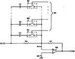
한편 마이콤(301)의 포오트 P1-P4에는 각각 훅크스위치(317), 콜스위치(318), 비상전화기의 어드레스를 지정하는 어드레스 지정스위치(319) 및 후술하는 초기상태의 송신부 등화회로(303) 및 수신부 등화회로(302)의 이득의 설정을 마이콤(301)에게 알려주는 루프스위치(320)이 접속된다.On the other hand, the ports P1-P4 of themicrocomputer 301 have ahook switch 317, acall switch 318, anaddress designation switch 319 for designating an address of an emergency telephone, and a transmitter equalizing circuit 303 in an initial state described later. And aloop switch 320 for informing themicrocomputer 301 of the setting of the gain of thereceiver equalization circuit 302.

또한 Vcc는 5볼트의 직류공급전압이며, R1-R11은 저항을 나타내며 상기 콜스위치(318)는 비상전화기 사용자가 비상호출을 할 경우 사용하는 버튼식 스위치이며, 어드레스 지정스위치(319)는 병렬 접속된 비상전화기가 6대라 가정하여 구분할 수 있게 지정하는 스위치로서 루프스위치(320)과 함께 디프(Dip) 스위치가 사용될 수 있다.In addition, Vcc is a DC supply voltage of 5 volts, R1-R11 represents a resistance, thecall switch 318 is a button type switch used when an emergency telephone user makes an emergency call, the addressingswitch 319 is connected in parallel A dip switch may be used together with theloop switch 320 as a switch for designating that 6 emergency telephones can be distinguished.

제4도는 제2도 및 제3도에서 사용하는 수신부 등화회로 및 송신부 등화회로 구체회로도를 나타낸 도면이며, 제5도는 선로의 3주파수에 따른 특성곡선으로써 실선은 통화로의 길이 I에 대해 X만큼 증가할 경우의 주파수에 따른 이득 감쇄곡선을 보상하기 위한 곡선을 나타낸 것이다.4 is a detailed circuit diagram of a receiver equalizing circuit and a transmitter equalizing circuit used in FIGS. 2 and 3, and FIG. 5 is a characteristic curve according to three frequencies of a line, and the solid line is X by the length I of the communication path. It shows a curve for compensating a gain attenuation curve with frequency when increasing.

사설교환기의 중계대에 있는 교환원과 비상전화기의 사용자가 통화를 할 경우 비상전화기의 위치가 사설교환기와 장거리 이격하여 있게 된다. 따라서 음성대역의 신호는 통신 거리가 증가함에 따라 주파수에 따른 이득 감쇄는 증하게 된다. 따라서 상기와 같은 주파수에 따른 이득감쇄를 보상하기 위해서는 점선과 같은 특성을 갖는 회로의 설계가 필요하게 된다.When the operator at the transit station of the private exchange and the user of the emergency telephone make a call, the location of the emergency telephone is long distance from the private exchange. Therefore, the gain of the voice band increases with increasing frequency as the communication distance increases. Therefore, in order to compensate the gain attenuation according to the frequency as described above, it is necessary to design a circuit having a characteristic such as a dotted line.

제4도를 참조하면 입력단자(61)는 저항 RA를 통해 연산증폭기(63)의 반전단자(64)와 접속되며, 비반전단자(65)는 접지되어 있고, 저항 Rf가 상기 단자(64)와 상기 연산증폭기(63)의 출력단자(62) 사이에 접속되어 있다. 또한 상기 저항 RA에는 캐패시터 Cn과 스위치 Sn이 직렬접속(여기서 n은 1,2,3…의 정수)되어 상기 저항 RA와 병렬접속되어 있고, 상기 스위치 Sn에는 상기 스위치를 온/오프시키는 제어신호 입력라인(60)이 각각 접속되어 있다.Referring to FIG. 4, the input terminal 61 is connected to the inverting terminal 64 of the operational amplifier 63 through the resistor RA , the non-inverting terminal 65 is grounded, and the resistor Rf is connected to the terminal 64. ) And the output terminal 62 of the operational amplifier 63.A capacitor Cn and a switch Sn are connected in series with each other in the resistor RA (where n is an integer of 1, 2, 3, ...), and are connected in parallel with the resistor RA. The switch Sn controls the on / off of the switch. Signal input lines 60 are respectively connected.

지금 스위치 Sn이 온 되었을 시의 합성 용량을 Cs라 하면 저항 RA와의 합성 임피던스 절대값 Zi는 하기식과 같이 쓸수 있다.If the combined capacitance at the time of switch Sn is now Cs, the absolute value of the combined impedance Zi with the resistance RA can be written as follows.

Figure kpo00012
Figure kpo00012

여기서 주파수를 f라하면 W=2

Figure kpo00013
f이므로, 제4도의 등화회로의 이득 G0는 하기 식과 같이 쓸수 있게 된다.Where f = 2
Figure kpo00013
Since f, the gain G0 of the equalization circuit of FIG. 4 can be written as follows.

Figure kpo00014
Figure kpo00014

그러므로 제(2)식에서 알 수 있는 바와같이 스위치 S1-Sn을 순차로 온시키면 Cs값이 커지기 때문에 이득을 증가시킬 수 있고, 오프시켜 나가면 이들을 줄일 수 있게 된다. 따라서 제4도의 제어신호 입력라인(60)은 제3도의 라인(253) 및 제2도의 라인(225)에 대응시켜 접속하면 되고, 등화제어동작은 마이콤(301)및 중앙처리장치(200)에서 출력하는 제어신호로 수행하면 된다.Therefore, as can be seen from equation (2), when the switches S1-Sn are sequentially turned on, the value of Cs increases, so that the gain can be increased, and if turned off, these can be reduced. Therefore, the controlsignal input line 60 of FIG. 4 may be connected in correspondence with theline 253 of FIG. 3 and theline 225 of FIG. 2, and the equalization control operation may be performed by themicrocomputer 301 and thecentral processing unit 200. This can be done with the output control signal.

지금 전용선의 통신로(90)에서 6대의 비상전화기(80)가 병렬로 접속되어 있다고 가정하고, 제어장치(110)과 비상전화기(80) 사이의 통신방식의 구성도를 제6도를 참조하여 설명한다.Suppose now that sixemergency telephones 80 are connected in parallel in thecommunication line 90 of the dedicated line, referring to FIG. 6 for a schematic diagram of the communication system between thecontrol apparatus 110 and theemergency telephone 80. Explain.

제6도(a)(b)를 참조하면, 타임슬롯 TS1-TS10은 각각 100mSec의 시간간격을 갖는 시간구분으로서 반복된다. 따라서 타임슬롯 TS1-TS6에는 각각 다른 복합주파의 아나로그 신호가 비상전화기 교류신호로 지정되어 실리게된다. 이때 제어장치의 송신시(제6도(a))의 경우 각 타임슬롯의 초기 60mSec만 상기 복합주파수가 실리게 되며, 나머지 40mSec은 시스템의 소자들의 동작 타이밍을 고려하여 이유를 남겨놓는다. 비상전화기(80)의 송신시(제6도(b))도 마찬가지이다.Referring to Fig. 6 (a) and (b), the timeslots TS1-TS10 are repeated as time segments each having a time interval of 100mSec. Accordingly, analog signals of different complex frequencies are designated as emergency telephone AC signals in the timeslots TS1-TS6. At this time, in case of transmission of the control device (Fig. 6 (a)), only the initial 60mSec of each time slot is loaded with the complex frequency, and the remaining 40mSec leaves a reason in consideration of the operation timing of the elements of the system. The same applies to the transmission of the emergency telephone 80 (Fig. 6 (b)).

또한 타임슬롯 TS7-TS10은 본시스템이 진단기능을 수행하기 위한 타임슬롯으로써, 종 400mSec중 초기 360mSec만이 진단기능을 수행하기 위한 복합주파수가 실리는 기간으로 사용된다. 또한 상기 타임슬롯중 TS10은 프레임 동기신호가 실릴수도 있는 타임슬롯으로써, 프레임 동기신호가 실리는 경우는 이 프레임 동기신호가 실리는 TS7-TS10의 타임슬롯에서 진단기능은 휴지상태로 사용하게 된다.In addition, time slot TS7-TS10 is a time slot for the system to perform the diagnostic function, and only the initial 360mSec among the 400mSec species is used as the period in which the complex frequency for performing the diagnostic function is loaded. In the time slots, TS10 is a time slot in which a frame synchronizing signal may be carried. When the frame synchronizing signal is carried, the diagnostic function is used in a time slot of the TS7-TS10 in which the frame synchronizing signal is carried.

또한 제어장치(100)의 송신시, 예를들어 1번 비상전화기를 지정하는 타임슬롯을 TS1이라 가정할 경우 1번 비상전화기가 제6도(a)의 프레임 구성도를 수신하여 송신할 경우에는 제6도(b)에 도시한 바와같이 4번째의 타임슬롯에서 자기의 신호를 실어 제어장치(110) 측으로 송신을 하게 된다.When thecontrol device 100 transmits, for example, assuming that the time slot designating theemergency phone 1 is TS1, theemergency phone 1 receives and transmits the frame diagram of FIG. 6 (a). As shown in FIG. 6 (b), the signal is loaded to thecontrol device 110 in the fourth time slot.

따라서 제6도에 도시한 화살표와 같이 제어장치의 송신에 대해 각각의 송신은 대응관계를 갖게된다. 따라서 PCM의 종래의 교환기에서의 프레임 구성에 따른 응답은 항상 1프레임 늦게 이루어짐에 비해 신속하게 시간을 절약하여 상호 교신을 할 수 있는 이점을 갖게 된다. 또한 사설교환기에는 제2도의 제어장치(110)의 카아드가 다수 접속되어 장거리를 소정거리마다 분할하여 통신을 할 수도 있도록 실시된다. 또한 제어장치(110)에는 통신로(90)가 2개 병렬로 접속되어 총 12대의 비상전화기가 6대씩 병렬로 접속된다.Therefore, as shown by the arrow shown in FIG. 6, each transmission has a correspondence with respect to the transmission of the control apparatus. Therefore, the response according to the frame configuration in the conventional switchboard of the PCM has the advantage that it can communicate with each other by saving time quickly compared to always being made one frame later. In addition, a large number of cards of thecontrol device 110 of FIG. 2 are connected to the private exchange, so that the long distance can be divided at predetermined distances for communication. In addition, thecontrol unit 110 is connected in parallel with twocommunication paths 90 so that a total of 12 emergency telephones are connected in parallel by six.

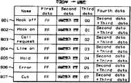
제7도는 본 발명에 따른 비상전화 시스템의 메세지 테이블 구성도로서, 제7(a)도는 제1도의 주제어부(100)에서 부제어부(102)로 전송되는 메시지 테이블이며, 제7(b)도는 제1도의 부제어부(102)에서 주제어부(100)로 전송되는 메시지 테이블이고, 제7(c)도는 부제어부(102)에서 제어장치(110)로 전송되는 메시지 테이블이며, 제7(d)도는 제어장치(110)에서 부제어부(102)로 전송되는 메세지 테이블이고, 제7(e)도는 주제어부(100)에서 상황판(107)으로 전송되는 메세지 테이블이며, 제7(f)도는 제어장치(110)에서 비상전화기(80)로 전송되는 메세지 테이블이고, 제7(g)도는 비상전화기(80)에서 제어장치(110)로 전송되는 메세지 테이블이다. 여기서 데이터는 16진수로 나타낸 것임을 유의하여야 한다. 또한 제7(f)도와 제7(g)의 데이터는 DTMF 송신회로 및 DTMF 수신회로에서 사용되는 16진수의 데이터들임을 유의해야 한다.7 is a message table configuration diagram of an emergency call system according to the present invention. FIG. 7 (a) is a message table transmitted from themain controller 100 of FIG. 1 to thesub-control unit 102. FIG. 7 is a message table transmitted from thesub-control unit 102 of FIG. 1 to themain control unit 100. FIG. 7 (c) is a message table transmitted from thesub-control unit 102 to thecontrol unit 110. FIG. FIG. 7 is a message table transmitted from thecontroller 110 to thesub-control unit 102. FIG. 7 (e) is a message table transmitted from themain controller 100 to thestatus plate 107. FIG. The message table transmitted to theemergency telephone 80 at 110, and (g) is a message table transmitted from theemergency telephone 80 to thecontrol device 110. Note that the data here are in hexadecimal. It should be noted that the data of the seventh (f) and the seventh (g) are hexadecimal data used in the DTMF transmitting circuit and the DTMF receiving circuit.

상기 제7(a)-(g)의 테이블에 나타난 각 메세지들에 있어서, Gain up은 이득상향 메세지, Gain down은 이득하향 메세지, Busy는 화중음 메세지, Hold는 보류음 메세지, Line on은 가입자를 통화상태로 하기 위한 메세지, Cut는 가입자의 통화를 절단하기 위한 메세지, Call ack는 소정의 콜요청에 대응하여 링백톤을 요구하는 메세지, Gain set는 제어장치의 이득조정 메세지, Cu restart는 제어장치 재시동 메세지, Codec on은 코덱 온을 위한 메세지, Codec off는 코덱 오프를 위한 메세지, Call Request는 콜요청음 메세지, Hook off는 전화기의 훅오프상태 메세지, Hook on은 전화기의 훅온상태 메세지, Cu start는 제어장치 시동 메세지, Gain end는 이득조정 종료상태 메세지, Call response는 콜상태 응답 메세지, Voicegain은 비상전화기의 핸드

Figure kpo00015
의 상태검사 메세지, Electronic gain은 자동이득조정 메세지, Error는 비상전화기의 에러상태 메세지, Voice gain test는 비상전화기의 핸드
Figure kpo00016
의 상태검사 메세지, Electronic gain test는 자동이득조정 메세지, Sync는 프레임 동기신호 메세지이다.In each of the messages shown in the seventh (a)-(g) tables, Gain up is a gain up message, Gain down is a gain down message, Busy is a busy tone message, Hold is a pending tone message, and Line on is a subscriber. Message to cut a call, Cut is a message to cut a subscriber's call, Call ack is a message requesting a ringback tone in response to a predetermined call request, Gain set is a gain adjustment message of a controller, and Cu restart is controlled. Device restart message, Codec on is message for codec on, Codec off is message for codec off, Call Request is call request sound message, Hook off is phone hook off status message, Hook on is phone hook on status message, Cu start is control device start message, gain end is gain adjustment end status message, call response is call status response message, voicegain is emergency phone's hand
Figure kpo00015
Status check message, Electronic gain is automatic gain adjustment message, Error is emergency status error message message, Voice gain test is emergency phone handset
Figure kpo00016
Condition check message, Electronic gain test is automatic gain adjustment message, and Sync is frame sync signal message.

제8도(a)는 제어장치(110)의 핸드

Figure kpo00017
검사 흐름도이며, 제8도(b)는 비상전화기(80)의 핸드
Figure kpo00018
검사 흐름도로서, 제어장치(110)에서 일정 주기로 보이는 게인 테스트 메세지를 출력하면 비상전화기(80)에서 상기메세지에 의해 보이는 테스트 루프를 형성하며, 이후 제어장치(110)에서 테스트톤 신호를 출력하고 비상전화기(80)에서 형성된 테스트 루프를 통해 제어장치(110)에 이를 재수신하여 핸드
Figure kpo00019
의 상태를 검사한다.8A illustrates a hand of thecontrol device 110.
Figure kpo00017
Fig. 8 (b) shows the hand of theemergency telephone 80.
Figure kpo00018
As an inspection flow chart, outputting a gain test message at a certain period from thecontrol device 110 forms an test loop shown by the message in theemergency telephone 80, and then outputs a test tone signal from thecontrol device 110 and makes an emergency call. Re-receives it to thecontrol device 110 through a test loop formed in thetelephone 80
Figure kpo00019
Check the condition of

상술한 구성에 의거 본 발명을 제1도-제8도를 참조하여 상세히 설명한다.Based on the above-described configuration, the present invention will be described in detail with reference to FIGS.

사설교환기(10)의 내부에는 제2도의 제어장치(1l0)가 다수개 접속되어 있으며 장거리를 소정거리 단위로 분할하여 통신한다. 또한 상기 제어장치(110)에는 통신로(90)가 연결되어 병렬 접속된 비상전화기(80)의 동작을 제어한다. 상기와 같은 비상전화기 시스템의 전반적인 동작은 본원 출원인에 의해 동일자로 특허 출원된 출원번호 제87-11292호에 상세히 개시되어 있다.A plurality ofcontrol devices 110 in FIG. 2 are connected inside theprivate exchange 10, and the long distance is divided by a predetermined distance to communicate. In addition, thecontrol device 110 is connected to thecommunication path 90 controls the operation of theemergency telephone 80 is connected in parallel. The overall operation of such an emergency telephone system is described in detail in patent application No. 87-11292 filed by the applicant of the same patent.

본 발명은 상기와 같은 비상전화 시스템에서 비상전화기(80)의 핸드

Figure kpo00020
(323)의 상태를 원격지에서 검사하는 방법을 제시하고자 한다. 이는 상술한 바와 같이 비상전화기(80)의 사용 용도는 긴급한 상황 발생시 비상 통화를 수행하고자 함을 목적으로 하는데, 비상전화기(80)의 핸드
Figure kpo00021
(323)이 고장 상태이면 긴급 통화를 수행할 수 없다. 그러나 비상전화기(80)가 원거리에 일정 간격으로 이격되어 있으므로 헨드
Figure kpo00022
(323)의 상태를 수동으로 검사하는 데에는 어려움이 따르게 된다. 따라서 본 발명에서는 원격지의 비상전화기(80)의 핸드
Figure kpo00023
(323)을 중앙제어부에서 일정 주기로 자동 검사하여 핸드
Figure kpo00024
(323)의 상태를 분석하게 된다.The present invention is the hand of theemergency telephone 80 in the emergency call system as described above
Figure kpo00020
A method of remotely checking the state of 323 is provided. The purpose of using theemergency call 80 as described above is to carry out an emergency call when an emergency situation occurs, the hand of theemergency call 80
Figure kpo00021
If 323 is out of order, emergency calls cannot be made. However, the emergency telephone (80) is remotely spaced at regular intervals, so the hand
Figure kpo00022
It is difficult to manually check the state of 323. Therefore, in the present invention, the hand of theemergency telephone 80 of the remote place
Figure kpo00023
Automatically check the 323 at regular intervals
Figure kpo00024
The state of 323 is analyzed.

먼저 제어장치(110)의 중앙처리장치(200)는 비상전화기(80)가 훅크 "온"되어 있는 상태에서 일정 주기로 비상전화기(80)의 핸드

Figure kpo00025
(323)을 검사하기 위한 진단메세지를 발생한다. 즉 제8도(a)의 (31)단계에서 핸드
Figure kpo00026
(323)의 검사 시간이 되었음을 인지하면, 중앙처리장치(200)는 (32)단계에서 라인(220)으로 제7도(f)의 보이스 게인 테스트 메세지(904)를 출력한다.First, thecentral processing unit 200 of thecontrol device 110 is a hand of theemergency telephone 80 at regular intervals while theemergency telephone 80 is hooked "on".
Figure kpo00025
A diagnostic message for checking 323 is generated. That is, the hand in the step (31) of FIG.
Figure kpo00026
If it is determined that the test time 323 is reached, theCPU 200 outputs the voicegain test message 904 of FIG. 7 f to theline 220 instep 32.

그러면 DTMF 송신회로(201)는 상기 보이스 게인 테스트 메세지(904)를 DTMF 신호로 변환하며 라인(222)을 통해 송신등화회로(203)로 인가한다. 그러면 제4도와 같은 구성의 송신등화회로(203)는 라인(225)을 통한 중앙처리장치(200)의 이득 제어신호에 의해 송신레벨을 조정하며 송신라인 인터페이스(250)를 통해 송신라인(215)로 전송한다. 그러면 상기 DTMF 신호는 비상전화기(80)의 수신라인(250) 및 수신라인 인터페이스(324)를 통해 수신부 등화회로(302)로 인가되며, 제4도와 같은 구성을 갖는 수신부 등화회로(302)는 라인(253)을 통한 마이콤(301)의 이득 제어신호에 의해 수신 레벨을 조정한 후 DTMF 수신회로(304)로 인가한다.TheDTMF transmission circuit 201 then converts the voicegain test message 904 into a DTMF signal and applies it to thetransmission equalization circuit 203 vialine 222. Then, thetransmission equalization circuit 203 having the configuration shown in FIG. 4 adjusts the transmission level according to the gain control signal of thecentral processing unit 200 through theline 225, and transmits thetransmission line 215 through thetransmission line interface 250. To send. Then, the DTMF signal is applied to thereceiver equalization circuit 302 through thereceiver line 250 and thereceiver line interface 324 of theemergency telephone 80, and thereceiver equalizer circuit 302 having the configuration as shown in FIG. The reception level is adjusted by the gain control signal of themicrocomputer 301 through 253 and then applied to theDTMF receiving circuit 304.

이때 상기 DTMF 수신회로(304)는 상기 수신부 등화회로(302)를 출력하는 DTMF 신호를 수신하여 디지탈 신호 형태의 보이스 게인 테스트 메세지(904)를 복원한 후 마이콤(301)으로 인가한다.At this time, theDTMF receiving circuit 304 receives the DTMF signal outputting thereceiver equalizing circuit 302, restores the voicegain test message 904 in the form of a digital signal, and applies it to themicrocomputer 301.

그러면 상기 마이콤(301)은 제8도(b)의 (41)단계에서 이를 인지하고, (42)단계에서 마이콤(30l)은 라인(255)을 통해 Rx스위치(307)를 "온"시키고, 라인(266)을 통해 Tx스위치(310)를 온시키며, 라인(261)을 통해 제2진단스위치(309)를 "온"시킨다. 또한 라인(263)을 통해 사이드 톤 스위치(322)를 "오프"시키고, 라인(262)을 통해 제1진단스위치(308)를 오프시킨다. 따라서 상기 스위치(307,309,310)가 "온" 상태가 되므로 핸드

Figure kpo00027
(323)의 수화기(326)의 송화기(327)와 제2송화기(315) 및 제2수화기(316)를 통한 음향 결합통로가 형성되어 핸드
Figure kpo00028
(323)의 상태를 검사하기 위한 테스트 루프가 형성된다.Then, themicrocomputer 301 recognizes this in step (41) of FIG. 8 (b), and instep 42, the microcomputer 30l “on” theRx switch 307 through theline 255, TheTx switch 310 is turned on via the line 266, and the second diagnostic switch 309 is turned on via theline 261. In addition, theside tone switch 322 is "off" through theline 263, and the first diagnostic switch 308 is turned off via the line 262. Therefore, theswitch 307, 309, 310 is in the "on" state, so the hand
Figure kpo00027
An acoustic coupling path is formed through the handset 327 of thehandset 326 and thesecond handset 315 and thesecond handset 316 of 323.
Figure kpo00028
A test loop is formed to check the state of 323.

이후 상기 마이콤(301)은 (43)단계에서 라인(265)을 통해 제7도(g)의 테스트 액크널리지 메세지(1006)를 출력한다. 그러면 상기 테스트 액크널리지 메세지(1006)을 입력하는 DTMF 송신회로(305)는 이를 DTMF 신호로 변환하며, 송신부 등화회로(303)는 상기 DTMF 신호를 수신하여 라인(253)을 통해 마이콤(301)의 이득 제어신호에 의해 송신 레벨을 조정한 후 송신라인 인터페이스(325)를 통해 송신라인(251)으로 전송한다. 이후 제어장치(110)의 수신라인(216)을 통해 수신되는 DTMF 신호는 상기 중앙처리장치(200)의 제어하에 수신등화회로(204)에서 수득 이득이 조정된 후 DTMF 수신회로(202)로 인가된다. 그리고 상기 DTMF 수신회로(202)의 출력인 테스트 액크널리지 메세지(1006)는 중앙처리장치(200)의 출력인 테스트 액크널리지 메세지(1006)는 중앙처리장치(200)로 인가되며, 중앙처리장치(200)는 제 8도(a)의 (32)단계에서 이를 인지하고, (34)단계에서 테스트톤 발생회로(208)를 제어하여 1000HZ의 테스트톤 신호를 출력시킨다.Thereafter, themicrocomputer 301 outputs the test acknowledgemessage 1006 of FIG. 7 g through theline 265 instep 43. Then, theDTMF transmission circuit 305 for inputting the test acknowledgemessage 1006 converts the DTMF signal into a DTMF signal, and the transmitter equalization circuit 303 receives the DTMF signal and receives themicrocomputer 301 through theline 253. After adjusting the transmission level according to the gain control signal of the transmission through the transmission line interface 325 to thetransmission line 251. After that, the DTMF signal received through thereceiving line 216 of thecontrol device 110 is applied to theDTMF receiving circuit 202 after the gain obtained by the receivinglight circuit 204 is adjusted under the control of theCPU 200. do. Thetest acknowledgement message 1006, which is the output of theDTMF receiving circuit 202, is applied to thecentral processing unit 200, and thetest acknowledgement message 1006, which is the output of thecentral processing unit 200, is applied to thecentral processing unit 200. Theapparatus 200 recognizes this instep 32 of FIG. 8A, and controls the testtone generating circuit 208 instep 34 to output a test tone signal of 1000 HZ.

그러면 상기 테스트톤 신호는 송신등화회로(203) 및 송신라인 인터페이스(250)를 통해 비상전화기(80)측으로 전송된다. 따라서 상기 테스트톤 신호는 이미 형성되어 있는 음향 결합 테스트 루프에 의해 수신라인 인터페이스(324)→수신부 등화회로(302)→Rx스위치(307)→수신증폭기(311)를 거쳐 핸드

Figure kpo00029
(323)의 수화기(326)로 공급되며, 상기 수화기(326)에서 발생되는 음향 신호는 대향되어 연결된 제2송화기(315)에서 다시 전기적 신호로 변환된다.The test tone signal is then transmitted to theemergency telephone 80 through thetransmission light circuit 203 and thetransmission line interface 250. Accordingly, the test tone signal is passed through thereceiving line interface 324 → thereceiver equalization circuit 302 → theRx switch 307 → the receivingamplifier 311 by an acoustic coupling test loop.
Figure kpo00029
Thereceiver 326 is supplied to thereceiver 326, and the acoustic signals generated by thereceiver 326 are converted back into electrical signals by thesecond transmitter 315 connected to each other.

그리고 상기 제2송화기(315)의 출력은 제2진단스위치(309)→증폭기(313)를 통해 제2수화기(316)로 공급되며, 제2수화기(316)에서 발생되는 음향 신호는 대향되어 연결된 핸드

Figure kpo00030
(323)의 송화기(327)에서 전기적 신호로 변환된다. 따라서 핸드
Figure kpo00031
(323)의 수화기(326)는 제2송화기(315)와 대향되어 음향 결합되고, 핸드
Figure kpo00032
(323)의 송화기(327)는 제2수화기(316)와 대향되어 음향 결합되므로서, 핸드
Figure kpo00033
(323)이 정상적인 상태일시에는 수화기(326)→제1송화기(315)→제2수화기(3l6)→송화기(327)로 이루어지는 음향 결합 통로를 통해 테스트톤 신호가 전달된다.The output of thesecond handset 315 is supplied to thesecond handset 316 through the second diagnostic switch 309 → theamplifier 313, and the acoustic signals generated by thesecond handset 316 are connected to each other. hand
Figure kpo00030
In the transmitter 327 of 323 is converted into an electrical signal. Hand
Figure kpo00031
Thehandset 326 of 323 is acoustically coupled to face thesecond transmitter 315,
Figure kpo00032
The handset 327 of 323 is acoustically coupled to face thesecond handset 316, so that the hand
Figure kpo00033
When 323 is in a normal state, the test tone signal is transmitted through an acoustic coupling path consisting of thehandset 326 → thefirst handset 315 → thesecond handset 316 → the handset 327.

상기 핸드

Figure kpo00034
(323)의 송화기(327) 출력은 송신증폭기(312)→송신부 등화회로(303)→Tx스위치(310)→송신라인 인터페이스(325)를 통해 제어장치(110)로 전송된다.The hand
Figure kpo00034
The output of the transmitter 327 of 323 is transmitted to thecontrol apparatus 110 via thetransmission amplifier 312 → transmitter equalization circuit 303 →Tx switch 310 → transmission line interface 325.

이후 제어장치(110)는 수신라인 인터페이스(206) 및 수신등화회로(204)를 통해 상기 비상전화기(80)에서 되돌아오는 테스트톤 신호를 수신하며, 절대값회로(209)에서 이를 직류전압으로 변환한 후, A/D변환기(210)에서 상기 직류 레벨의 전압을 디지탈 데이터로 변환한다. 그러면 중앙처리장치(200)는 제8도(a)의 (35)단계에서 상기 A/D변환기(210)의 출력을 리드하며, (36)단계에서 상기 A/D변환 데이터를 이용하여 제7도(d)의 보이스 게인 메세지(707)를 발생한 후 피포(213)에 라이트시킨다.Thereafter, thecontrol device 110 receives the test tone signal returned from theemergency telephone 80 through thereception line interface 206 and thereception light circuit 204, and converts it into a DC voltage in theabsolute value circuit 209. After that, the A /D converter 210 converts the voltage of the DC level into digital data. Then, thecentral processing unit 200 reads the output of the A /D converter 210 in step (35) of FIG. 8 (a), and uses the A / D conversion data in step (36). Thevoice gain message 707 of FIG.

그러면 부제어부(102)는 상기 보이스 게인 메세지(707)를 수신한 후 주제어부(100)에 처리할 수 있도록 제7도(b)의 보이스 게인 메세지(507)를 발생하여 서브 시리얼 인터페이스(104)를 통해 메인 시리얼 인터페이스(103)로 출력한다. 이때 주제어부(100)는 메인 시리얼 인터페이스(103)를 통해 상기 보이스 게인 메세지(507)를 수신하여 보이스 게인 값을 메모리부(101)에 저장한다. 이후 주제어부(100)는 상기 보이스 게인 값을 분석하여 보이스 게인이 현저하게 작은 경우에는 해당 비상전화기(80)의 핸드

Figure kpo00035
(323) 검사결과를 에러 상태로 표시한다.Then, thesub-control unit 102 receives thevoice gain message 707 and generates thevoice gain message 507 of FIG. 7 (b) to process themain control unit 100 so that the subserial interface 104 can receive thevoice gain message 707. Output to the mainserial interface 103 through. At this time, themain control unit 100 receives thevoice gain message 507 through the mainserial interface 103 and stores the voice gain value in thememory unit 101. Subsequently, themain controller 100 analyzes the voice gain value and, when the voice gain is remarkably small, the hand of theemergency telephone 80.
Figure kpo00035
(323) The test results are displayed in an error state.

따라서 상기 비상전화기(80)의 핸드

Figure kpo00036
(323) 검사시, 음향 결합 루프인 핸드
Figure kpo00037
수화기(326)→제2송화기(315)→제2수화기(316)→핸드
Figure kpo00038
송화기(327)의 통로를 형성하게 되는데, 핸드
Figure kpo00039
(323)에 이상상태가 발생되면 상기 음향 결합 루프를 형성하지 못하므로 핸드
Figure kpo00040
(323)의 통화 불능 상태를 인지할 수 있으며, 또한 테스트 신호 감시시에도 기준 레벨 이하의 신호일시에는 주제어부(100)에서 이를 감지할 수 있게 된다.Therefore, the hand of the emergency telephone (80)
Figure kpo00036
(323) During inspection, the hand which is the acousticcoupling loop
Figure kpo00037
Handset
326 →Second Handset 315 →Second Handset 316 → Hand
Figure kpo00038
It forms the passage of the talker 327, the hand
Figure kpo00039
If an abnormal condition occurs at 323, the sound coupling loop may not be formed.
Figure kpo00040
The call disconnection state 323 may be recognized, and themain control unit 100 may detect the signal when the signal is below the reference level even when the test signal is monitored.

상술한 바와같이 비상전화기의 핸드

Figure kpo00041
상태를 일정 주기마다 점검하여 고장 유무를 원격 이격된 위치에서 자동 진단할 수 있으며, 이로 인해 비상 전화 시스템의 비상통화 기능을 향상 가능 상태로 유지할 수 있는 동시에 시스템 유지 보수를 용이하게 수행할 수 있는 이점이 있다.As described above, the emergency telephone hand
Figure kpo00041
The status can be checked at regular intervals to automatically diagnose failures in remotely spaced locations, which allows the emergency call system's emergency call function to be improved, while at the same time making system maintenance easier. There is this.

Claims (1)

Translated fromKorean
사설교환기(10)의 내부에 수용되어 통화 라인과 교환 제어부간에 데이타 통신을 수행하는 동시에 통화라인과 교환 스위치 회로간에 음성신호를 제어하는 제어장치(110)와, 핸드
Figure kpo00042
의 수화기(326) 및 송화기(327)에 각각 대향되어 제2송화기(315) 및 제2수화기(316)가 연결되며, 상기 제2송화기(315)와 제2수화기(316) 사이에 진단스위치(309)를 연결하여 음향 결합 루프를 형성하는 비상전화기(80)를 구비하여 상기 제어장치(110)에서 원격 이격되어 통화 라인에 다수개의 비상전화기(80)가 병렬 접속되는 비상전화 시스템에 있어서, 상기 제어장치(110)에서 일정 주기로 보이스 게인 테스트 메세지를 비상전화기(80)로 송출하며, 상기 메세지를 수신하여 비상전화기(80)에서 상기 진단스위치(309)를 "온"시켜 음향 결합 테스트 루프를 형성하는 제1스텝(31,32,41,42)과, 상기 음향 결합 테스트 루프 형성후 비상전화기(80)에서 테스트 액크널리지 메세지를 제어장치로 출력하며, 상기 메세지에 의해 제어장치(110)에서 테스트톤 신호를 발생하여 비상전화기(80)의 음향 결합 테스트 루프를 통한 테스트톤 신호를 재수신하는 제2스텝(33,34,35,43,44)과, 상기 테스트톤 신호를 재수신한 제어장치(110)에서 보이는 게인 메세지를 발생하여 교환 제어부로 전송하며 교환제어부에서 보이스 게인값의 레벨을 분석하여 비상전화기(80)의 핸드
Figure kpo00043
고장 유무를 판단하는 제3스텝(36,45)로 이루어짐을 특징으로 하는 비상전화 시스템 비상전화기 핸드
Figure kpo00044
상태 검사 방식.A control device 110 accommodated in the private exchange 10 and performing data communication between the call line and the exchange control unit, and controlling a voice signal between the call line and the exchange switch circuit;
Figure kpo00042
Opposed to the handset 326 and the handset 327 of the second handset 315 and the second handset 316 is connected, the diagnostic switch between the second handset 315 and the second handset 316 ( In the emergency telephone system having an emergency telephone 80 to connect the 309 to form an acoustic coupling loop, a plurality of emergency telephones 80 are connected in parallel to the call line remotely spaced from the control device 110, The control device 110 transmits a voice gain test message to the emergency telephone 80 at regular intervals, and receives the message to " on " the diagnostic switch 309 in the emergency telephone 80 to form an acoustic coupling test loop. After the first steps (31, 32, 41, 42) and the acoustic coupling test loop is formed, the emergency telephone 80 outputs a test acknowledgment message to the control device, by the control device 110 by the message Generates test tone signal and makes emergency phone (80) A second step (33, 34, 35, 43, 44) for re-receiving the test tone signal through the acoustic coupling test loop of the signal and the gain message shown in the control unit 110 that has received the test tone signal again The handset of the emergency telephone 80 is transmitted to the control unit and the exchange control unit analyzes the level of the voice gain value.
Figure kpo00043
Emergency telephone system emergency telephone hand, characterized in that the third step (36,45) to determine whether there is a failure
Figure kpo00044
Health check method.
KR1019870011185A1987-10-051987-10-05 Handheld condition test method of emergency phone in emergency call systemExpiredKR900007707B1 (en)

Priority Applications (1)

Application NumberPriority DateFiling DateTitle
KR1019870011185AKR900007707B1 (en)1987-10-051987-10-05 Handheld condition test method of emergency phone in emergency call system

Applications Claiming Priority (1)

Application NumberPriority DateFiling DateTitle
KR1019870011185AKR900007707B1 (en)1987-10-051987-10-05 Handheld condition test method of emergency phone in emergency call system

Publications (2)

Publication NumberPublication Date
KR890007539A KR890007539A (en)1989-06-20
KR900007707B1true KR900007707B1 (en)1990-10-18

Family

ID=19265061

Family Applications (1)

Application NumberTitlePriority DateFiling Date
KR1019870011185AExpiredKR900007707B1 (en)1987-10-051987-10-05 Handheld condition test method of emergency phone in emergency call system

Country Status (1)

CountryLink
KR (1)KR900007707B1 (en)

Families Citing this family (1)

* Cited by examiner, † Cited by third party
Publication numberPriority datePublication dateAssigneeTitle
KR100326948B1 (en)*1999-07-242002-03-13다우전자통신 주식회사Apparatus For Detection Of State Of Emergence Telephone

Also Published As

Publication numberPublication date
KR890007539A (en)1989-06-20

Similar Documents

PublicationPublication DateTitle
US5519763A (en)Communication apparatus with wireless intercommunication
US4706244A (en)Frequency multiplexed telephone system
US4572928A (en)Key telephone system
KR900007707B1 (en) Handheld condition test method of emergency phone in emergency call system
US4445007A (en)Remote testing of subscriber line interface circuits
US4567332A (en)Four-wire telephone system with self-test means
KR910000355B1 (en)Emergency calling system
JP3721707B2 (en) TV door phone system
KR900007711B1 (en)Emergency call system
KR910000352B1 (en)Automatic gain control method in emergency calling system
KR900007710B1 (en)Automatic equalizing circuit of emergency call system
IE49774B1 (en)Digital telephone station
RU2010433C1 (en)Device for automatic radiotelephone communication
KR100765322B1 (en) Analog trunk matching device with variable matching and control method
RU1774516C (en)Device for controlling and checking of command transmission over telephone lines
JPH03114337A (en) telephone
JP2810726B2 (en) Telephone system
KR940008116B1 (en)Order-wire circuit between device
JP3162468B2 (en) Telephone device in remote monitoring control device
SU1125769A1 (en)Device for supervisory duplex operation
GB2204761A (en)Telephone system and terminal
JPS63178692A (en) button telephone device
JPH0113679B2 (en)
JPH01233870A (en)Telephone set
JPH04241562A (en)In-band signaling transmitter

Legal Events

DateCodeTitleDescription
A201Request for examination
PA0201Request for examination

Patent event code:PA02012R01D

Patent event date:19871002

Comment text:Request for Examination of Application

PA0109Patent application

Patent event code:PA01091R01D

Comment text:Patent Application

Patent event date:19871005

N231Notification of change of applicant
PN2301Change of applicant

Patent event date:19881128

Comment text:Notification of Change of Applicant

Patent event code:PN23011R01D

PG1501Laying open of application
E902Notification of reason for refusal
PE0902Notice of grounds for rejection

Comment text:Notification of reason for refusal

Patent event date:19900530

Patent event code:PE09021S01D

G160Decision to publish patent application
PG1605Publication of application before grant of patent

Comment text:Decision on Publication of Application

Patent event code:PG16051S01I

Patent event date:19900918

E701Decision to grant or registration of patent right
PE0701Decision of registration

Patent event code:PE07011S01D

Comment text:Decision to Grant Registration

Patent event date:19910103

GRNTWritten decision to grant
PR0701Registration of establishment

Comment text:Registration of Establishment

Patent event date:19910122

Patent event code:PR07011E01D

PR1002Payment of registration fee

Payment date:19910122

End annual number:3

Start annual number:1

PR1001Payment of annual fee

Payment date:19930330

Start annual number:4

End annual number:4

PR1001Payment of annual fee

Payment date:19941001

Start annual number:5

End annual number:5

PR1001Payment of annual fee

Payment date:19950922

Start annual number:6

End annual number:6

PR1001Payment of annual fee

Payment date:19960925

Start annual number:7

End annual number:7

PR1001Payment of annual fee

Payment date:19970812

Start annual number:8

End annual number:8

PR1001Payment of annual fee

Payment date:19980928

Start annual number:9

End annual number:9

PR1001Payment of annual fee

Payment date:19990927

Start annual number:10

End annual number:10

PR1001Payment of annual fee

Payment date:20000926

Start annual number:11

End annual number:11

PR1001Payment of annual fee

Payment date:20010924

Start annual number:12

End annual number:12

PR1001Payment of annual fee

Payment date:20020924

Start annual number:13

End annual number:13

PR1001Payment of annual fee

Payment date:20030922

Start annual number:14

End annual number:14

PR1001Payment of annual fee

Payment date:20040920

Start annual number:15

End annual number:15

PR1001Payment of annual fee

Payment date:20050921

Start annual number:16

End annual number:16

FPAYAnnual fee payment

Payment date:20060920

Year of fee payment:17

PR1001Payment of annual fee

Payment date:20060920

Start annual number:17

End annual number:17

EXPYExpiration of term
PC1801Expiration of term

Termination date:20080710

Termination category:Expiration of duration


[8]ページ先頭

©2009-2025 Movatter.jp