KR900007538B1 - Automatic toothbrush - Google Patents
Automatic toothbrushDownload PDFInfo
- Publication number
- KR900007538B1 KR900007538B1KR1019880014588AKR880014588AKR900007538B1KR 900007538 B1KR900007538 B1KR 900007538B1KR 1019880014588 AKR1019880014588 AKR 1019880014588AKR 880014588 AKR880014588 AKR 880014588AKR 900007538 B1KR900007538 B1KR 900007538B1
- Authority
- KR
- South Korea
- Prior art keywords
- toothbrush
- cylindrical case
- charger
- automatic
- rechargeable battery
- Prior art date
- Legal status (The legal status is an assumption and is not a legal conclusion. Google has not performed a legal analysis and makes no representation as to the accuracy of the status listed.)
- Expired
Links
Images


Classifications
- A—HUMAN NECESSITIES
- A46—BRUSHWARE
- A46B—BRUSHES
- A46B13/00—Brushes with driven brush bodies or carriers
- A46B13/02—Brushes with driven brush bodies or carriers power-driven carriers
Landscapes
- Brushes (AREA)
Abstract
Translated fromKoreanDescription
Translated fromKorean제1도는 본 발명의 실시예를 나타낸 전체단면도.1 is a cross-sectional view showing an embodiment of the present invention.
제2도는 제1도의 A-A선 단면도.2 is a sectional view taken along the line A-A of FIG.
제3도는 본 발명의 다른 실시예를 나티낸 단면도.3 is a cross-sectional view showing another embodiment of the present invention.
제4도는 본 발명의 또다른 실시예를 나타낸 단면도.4 is a cross-sectional view showing another embodiment of the present invention.
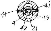
제5도는 제4도의 B-B선 단면도.5 is a cross-sectional view taken along the line B-B in FIG.
제6도는 본 발명에 있어서 치솔의 진동상태를 설명한 예시도.6 is an exemplary view illustrating a vibration state of the toothbrush in the present invention.
* 도면의 주요부분에 대한 부호의 설명* Explanation of symbols for main parts of the drawings
1 : 언버러스캠 2 : DC 모우터1: Unberus Cam 2: DC motor
2' : 샤후트 3, 3' : 시리콘고무벤드2 ':
12, 12' : 전류제한용콘덴서 13 : 원통형케이스12, 12 ': current limiting capacitor 13: cylindrical case
16 : 충전기16: charger
본 발명 DC 모우터축에 착설한 언바란스캠의 진동에너지에 의하여 치솔이 작은범위로 움직여서 치아를 자동으로 세척할 수 있게된 자동치솔에 관한 것으로서, 기존의 수동식치솔을 기통상부측의 밴드에 착탈교체 이용이 가능하게 하고, 기통내의 재충전밧데리는 AC 110V 또는 220V 어느 전원이라도 삽입충전으로 충전사용이 용이하도록 한 것이다. 종래에도 원주형의 부러쉬가 모우터에 의해 회전하도록 구성시킨 자동치솔은 있었다. 그러나 이는 치아에 접촉세척하는 부러쉬동작이 한쪽방향으로만 회전세척하므로 잇몸과 치아에 손상을 주는 문제점이 있을 뿐더러 치아좌우내외면을 부러쉬 회전방향에 따라 접촉시켜 주어야 하기때문에 이용에 불편점과 세척효율이 떨어지는 점이 있으며, 또 부착식원주형 부러쉬 1개를 계속 사용해야 하므로 자동치솔 구성에 비해 사용수명이 짧아 고가로 이용되는 문제점도 있었다.The present invention relates to an automatic toothbrush which is capable of automatically cleaning teeth by moving the toothbrush in a small range by vibrating energy of an unbalanced cam installed on a DC motor shaft, and using a conventional manual toothbrush on a band on the upper side of the cylinder. This enables the rechargeable battery in the cylinder to facilitate charging and charging by inserting and charging any of AC 110V or 220V power sources. Conventionally, there have been automatic toothbrushes in which a cylindrical brush is rotated by a motor. However, this is because the brush movement to wash the tooth is only rotated in one direction, so there is a problem that damages the gums and the teeth, and the left and right inner and outer surfaces of the tooth should be contacted according to the direction of brush rotation. There is a falling point, and also because the use of one stick-type columnar brush to continue to use, compared to the automatic toothbrush configuration has a short service life, there was also a problem that is used at high cost.
본 발명은 전술한 문제점을 제거함과 동시에 치솔은 기존의 것을 그대로 교체이용할 수 있게하고, 치솔은 언바란스캠의 회전관성력에 의하여 진동에너지를 가해주도록 하므로서 세척력이 우수하고, 잇몸에 맛사지 효과를 주므로서 잇몸의 혈액순환을 도울 수 있고, 그 치솔의 진동이 미세하여 잇몸과 치아에 손상을 주지않는 사용에 편리한 자동치솔을 제공할 목적으로 한 것으로 본 발명을 첨부도면에 의거하여 실시예를 더욱상세히 설명하면 다음과 같다.The present invention eliminates the above problems and at the same time the toothbrush can be used to replace the existing as it is, the toothbrush is excellent cleaning power by applying vibration energy by the rotational inertia force of the unbalanced cam, the gum by giving a massage effect to the gums According to the present invention in more detail on the basis of the accompanying drawings, the object of the present invention is to provide a convenient automatic toothbrush that can help blood circulation of the toothbrush is fine and vibration does not damage the gums and teeth. Same as
제1도는 본 발명의 내부구성을 나타낸 전체단면도로 플라스틱재로 되는 원통형케이스(13)의 상부길이방향으로 길게 요설된 치솔대상입홈(14)에 기본의 치솔대(9)를 삽입설치하여 실리콘고무밴드(3), (3')에 의해서 원통형케이스(13)에 치솔대(9)가 밀착고정되게 하였다.1 is a cross-sectional view showing the internal configuration of the present invention is a silicone rubber by inserting the
이 치솔대(9)는 착탈이 되므로 교체 사용할 수 있게되어 있다. 원통형케이스(13)의 내부 공간부(15)에는 길이로 수장된 재충전밧데리(5)에 의해 구동되는 DC 모우터(2)의 샤후트(2')에는 언바란스캠(1)이 부착되어 있다.Since this
이 언바란스캠(1)은 DC 모우터(2)의 회전에 의해서 무게 중심이 다른 편심회전을 하기 때문에 진동을 하게된다.The unbalanced cam 1 vibrates because the center of gravity makes an eccentric rotation with a different center of gravity by the rotation of the
이 진동은 그대로 DC 모우터(2) 자체를 진동시키게되므로 케이스(13) 또한 전체가 진동하여 실리콘고무밴드(3), (3')로서 밀착고정되어 있는 치솔대(9) 선단의 치솔(9')이 따라 진동하게 된다.Since the vibration vibrates the
또 진동에너지는 치솔(9')의 모가 가늘고 길기 때문에 대부분 치솔(9')에서 흡수되어 치아에까지는 적은 진동으로 전달되지만 진동에너지는 치솔의 모가 빳빳해서 언바란스캠(1) 진동에너지에 의해서는 전혀 구부러지는 현상이 없고 그대로 치아에까지 진동에너지가 전달된다.In addition, the vibration energy of the toothbrush 9 'is thin and long, so most of it is absorbed by the toothbrush 9' and transmitted to the teeth with little vibration, but the vibration energy of the toothbrush is so tight that the vibration energy of the unbalance cam (1) is not at all. There is no bending and vibration energy is transmitted to the teeth as they are.
이 진동에너지에 의한 치솔(9')은 치아표면 및 사이에 붙어있는 음식잔여물은 물론 치석이나 부착물에 진동에너지를 가해주어서 접촉세척과 함께 마찰접촉작용을 하나 치아에는 손상을 주지않고 잘 세척하게 된다.The toothbrush (9 ') by vibrating energy applies vibration energy to the tartar or attachments as well as the food residues attached to the surface of the teeth, and performs frictional contact with contact cleaning, but does not damage the teeth. do.
또한 이 진동에너지는 적은 진동이기 때문에 유연한 잇몸에서도 그대로 흡수되면서 잇몸의 내부 깊숙히까지 진동을 시켜주므로 혈액순환을 잘 시켜주는 맛사지 효과도 갖는다.In addition, this vibration energy is a small vibration, so even in the flexible gums as it is absorbed as it vibrates deeply inside the gum, it also has a massage effect to improve blood circulation.
그리고 원통형케이스(13) 후미에는 후미면(13')에 접한 코어(6)에 2차코일(8)을 권성하여 2차코일(8)의 일단부(8')는 정류다이오드(7)를 통해 DC 모우터(2)와 재충전밧데리(5)의 -측에 연결하고 2차코일(8)의 타단부(8")는 재충전 밧데리(5)의 +측에 연결하여 재충전 사용하도록 되어 있으며, 원통형케이스(13)의 중간하측에는 스위치(19)를 착설하여 재충전 밧데리(5)의 전원은 온, 오프시켜 사용이 편리하게 하였다.The
그리고 재충전밧데리(5)의 충전기(16)는, 원통형케이스(13)의 후미부를 끼워 충전케된 요입부(17)를 형성하고 그 요입부(17) 내부측에는 코어(18)를 착설하여 1차코일(8a)을 권성하고 그 1차코일(8a)의 양단에 각각 전류제한용콘덴서(12), (12')을 설치하여 스위치(20)를 통해 외부로 연결되는 전원코오드(12)에 연결 구성되어 있다.The
충전기(16)의 1차코일(8a)와 원통형케이스(13)의 후미면(13')에 근접설치되어 있으며 2차코일(8)의 관계는 변압기의 원리로 동작하지만 전류제한용콘덴서(12), (12')는 전류안정기의 작용을 한다.It is installed near the primary coil 8a of the
또 사용자가 충전기(16)에서 치솔을 사용하기 위해서 치솔의 원통형케이스(13)를 빼냈을 경우 충전기(16)에는 반쪽고어가 없는것과 같이되어 틈(Gap)이 확장되므로 많은 전류가 흘러 1차코일(8a)이 소손될 우려가 있으나 이때 전류제한용콘덴서(12), (12')의 임피던스가 높으므로 입력전압의 대부분을 전류제한용콘덴서(12), (12')에서 감당하게되어 1차코일(8a)의 전류는 일정하게 된다.In addition, when the user pulls out the
그러므로 충전기(16)는 AC 110V 또는 220V 어느 전원이든 안전하고 편리하게 사용되는 것으로, 어느 전원에서든지 재충전밧데리(5)에 충전사용이 되어 자동치솔사용이 편리하다.Therefore, the
제3도는 본 발명의 다른 실시예를 나타낸 단면도이다.3 is a cross-sectional view showing another embodiment of the present invention.
제3도의 자동치솔을 발진회로(30)를 원통형케이스(13)내부에 설치된 재충전밧데리(5)에 연결하고, 또 발진회로(30)에 연결된 코일(31)을 고어(32)에 권성하고 첨단에 고정자석(34)을 가진 진동간(33)을 코어(32)에 근접설치하여 코어(32)에 권성시킨 코일(31)의 전자력에 의하여 진동간(33)의 고정자석(434)이 반발과 흡인작용의 연속작동으로 진동에너지를 치솔(9')에 가해질 수 있도록 하고 기타구성은 전술한 제1도와 같이한다.The automatic toothbrush of FIG. 3 connects the
제4도는 본 발명의 또다른 실시예를 나타낸 단면도이다.4 is a cross-sectional view showing yet another embodiment of the present invention.
제4도의 자동치솔은 DC 모우터(2)의 샤후트(2')에 부착시킨 언바란스캠(1)에 크랭크간(40)이 착설되어서 언바란스캠(1)이 편심회전함에 따라 크랭크간(40)이 크랭크작용을 하게 하였으며, 이 크랭크간(40) 선단은 원통형케이스(13)의 선단양측의 지지핀(41), (41')에 진동체(42) 양측을 물어서 설치한 후부홈(43)에 끼워져서 유동될 수 있게 되어 있으며, 또 이 진동체(42)에는 기존의 치솔대(9)를 끼워 고정홈(21)에 고정한것으로, 이는 크랭크간(40)의 크랭크작용으로 진동체(42)를 진동시켜서 치솔에 진동에너지가 가해져서 세척할 수 있도록 되어 있다.In the automatic toothbrush of FIG. 4, the
이와같이 본 발명은 치솔의 원통형케이스(13) 후미부에 코어(6)에 권성시킨 2차코일(8) 및 2차코일 일단부(8')의 정류다이오드(7)가 착설되어 있으며, 재충전밧데리(5)와 연결구성되어져 있으므로 충전기(16)의 요입부(17)에 이를 끼워 재충전사용이 매우 간편할 뿐 아니라 충전기(16)의 1차코일(8a) 양단에는 전류제한용콘덴서(12), (12')가 각각 설치되어 있으므로 Ac 110V 또는 220V의 어느전원에도 편리하게 사용될 수 있는 것으로 특히 기존 치솔의 치솔대(9)는 원통형케이스(13)의 상부측 삽입홈(14)에 착탈할 수 있도록 실리콘고무밴드(3), (3')로서 고정설치하므로 교체사용이 가능하여 자동기구는 장기간 이용될 수 있으며, 또 치솔은 진동에너지에 의해서 치아와 접촉세척할 수 있는 방법을 취하고 있으므로 잇몸과 치아에 손상을 주지않고 가장 안전하고 효율적인 차솔질로서 치아를 세척할 수 있는 유일한 발명이다.Thus, in the present invention, the
Claims (1)
Translated fromKoreanPriority Applications (1)
| Application Number | Priority Date | Filing Date | Title |
|---|---|---|---|
| KR1019880014588AKR900007538B1 (en) | 1988-11-07 | 1988-11-07 | Automatic toothbrush |
Applications Claiming Priority (1)
| Application Number | Priority Date | Filing Date | Title |
|---|---|---|---|
| KR1019880014588AKR900007538B1 (en) | 1988-11-07 | 1988-11-07 | Automatic toothbrush |
Publications (2)
| Publication Number | Publication Date |
|---|---|
| KR900007364A KR900007364A (en) | 1990-06-01 |
| KR900007538B1true KR900007538B1 (en) | 1990-10-15 |
Family
ID=19279045
Family Applications (1)
| Application Number | Title | Priority Date | Filing Date |
|---|---|---|---|
| KR1019880014588AExpiredKR900007538B1 (en) | 1988-11-07 | 1988-11-07 | Automatic toothbrush |
Country Status (1)
| Country | Link |
|---|---|
| KR (1) | KR900007538B1 (en) |
Families Citing this family (1)
| Publication number | Priority date | Publication date | Assignee | Title |
|---|---|---|---|---|
| KR20040017068A (en)* | 2002-08-20 | 2004-02-26 | 김정선 | Electric toothbrush device |
- 1988
- 1988-11-07KRKR1019880014588Apatent/KR900007538B1/ennot_activeExpired
Also Published As
| Publication number | Publication date |
|---|---|
| KR900007364A (en) | 1990-06-01 |
Similar Documents
| Publication | Publication Date | Title |
|---|---|---|
| RU2389447C2 (en) | Electric tooth-brush | |
| US6955539B2 (en) | Characterization of motion of dual motor oral hygiene device | |
| US5934908A (en) | High-powered automatic electromechanical toothbrush | |
| AU770483B2 (en) | Toothbrush with vibrating head part | |
| US3160902A (en) | Mechanical toothbrush | |
| US7409741B2 (en) | Toothbrush with tuned vibrating head | |
| US5613259A (en) | High frequency electric toothbrush | |
| US6821119B2 (en) | Dual motor oral hygiene device | |
| US6140723A (en) | Vibration generating device and oral hygiene device using same | |
| CN101977566B (en) | electric toothbrush | |
| US20020092104A1 (en) | Acoustic toothbrush | |
| WO2011086960A1 (en) | Oral care device | |
| BR112018003980B1 (en) | Electronic device with a controlled direction of vibration transmission | |
| CN106937891A (en) | Self-generating electric toothbrush | |
| US2648787A (en) | Motor-driven toothbrush | |
| JP2009045202A (en) | Electric toothbrush and replacement brush | |
| WO2016127532A1 (en) | Electric toothbrush and vertical-brushing-type electric toothbrush | |
| JP2004065914A (en) | Ultrasonic hairbrush | |
| KR900007538B1 (en) | Automatic toothbrush | |
| KR101245713B1 (en) | The vibrating toothbrush with a function of turn-on by chewing | |
| JP2003164473A (en) | High-speed vibration toothbrush | |
| US20170141638A1 (en) | Cordless oscillatory hand held apparatus | |
| JP2003024403A (en) | Ultrasonic gum massager | |
| JPH0636426U (en) | Connector for electric interdental cleaning brush | |
| CN209377785U (en) | Electric toothbrush |
Legal Events
| Date | Code | Title | Description |
|---|---|---|---|
| A201 | Request for examination | ||
| PA0109 | Patent application | St.27 status event code:A-0-1-A10-A12-nap-PA0109 | |
| PA0201 | Request for examination | St.27 status event code:A-1-2-D10-D11-exm-PA0201 | |
| R17-X000 | Change to representative recorded | St.27 status event code:A-3-3-R10-R17-oth-X000 | |
| PG1501 | Laying open of application | St.27 status event code:A-1-1-Q10-Q12-nap-PG1501 | |
| E902 | Notification of reason for refusal | ||
| PE0902 | Notice of grounds for rejection | St.27 status event code:A-1-2-D10-D21-exm-PE0902 | |
| P11-X000 | Amendment of application requested | St.27 status event code:A-2-2-P10-P11-nap-X000 | |
| P13-X000 | Application amended | St.27 status event code:A-2-2-P10-P13-nap-X000 | |
| G160 | Decision to publish patent application | ||
| PG1605 | Publication of application before grant of patent | St.27 status event code:A-2-2-Q10-Q13-nap-PG1605 | |
| E701 | Decision to grant or registration of patent right | ||
| PE0701 | Decision of registration | St.27 status event code:A-1-2-D10-D22-exm-PE0701 | |
| GRNT | Written decision to grant | ||
| PR0701 | Registration of establishment | St.27 status event code:A-2-4-F10-F11-exm-PR0701 | |
| PR1002 | Payment of registration fee | St.27 status event code:A-2-2-U10-U11-oth-PR1002 Fee payment year number:1 | |
| PR1001 | Payment of annual fee | St.27 status event code:A-4-4-U10-U11-oth-PR1001 Fee payment year number:4 | |
| FPAY | Annual fee payment | Payment date:19940929 Year of fee payment:5 | |
| PR1001 | Payment of annual fee | St.27 status event code:A-4-4-U10-U11-oth-PR1001 Fee payment year number:5 | |
| LAPS | Lapse due to unpaid annual fee | ||
| PC1903 | Unpaid annual fee | St.27 status event code:A-4-4-U10-U13-oth-PC1903 Not in force date:19951016 Payment event data comment text:Termination Category : DEFAULT_OF_REGISTRATION_FEE | |
| PC1903 | Unpaid annual fee | St.27 status event code:N-4-6-H10-H13-oth-PC1903 Ip right cessation event data comment text:Termination Category : DEFAULT_OF_REGISTRATION_FEE Not in force date:19951016 | |
| PN2301 | Change of applicant | St.27 status event code:A-5-5-R10-R13-asn-PN2301 St.27 status event code:A-5-5-R10-R11-asn-PN2301 | |
| R18-X000 | Changes to party contact information recorded | St.27 status event code:A-5-5-R10-R18-oth-X000 | |
| R18-X000 | Changes to party contact information recorded | St.27 status event code:A-5-5-R10-R18-oth-X000 | |
| R18-X000 | Changes to party contact information recorded | St.27 status event code:A-5-5-R10-R18-oth-X000 | |
| P22-X000 | Classification modified | St.27 status event code:A-4-4-P10-P22-nap-X000 |