KR900007284B1 - Tear-open plap orifice on pack consisting of plastic-coated laminated material with a folded round fillet-sean closure and a process for producing the tearopen flap orifice - Google Patents
Tear-open plap orifice on pack consisting of plastic-coated laminated material with a folded round fillet-sean closure and a process for producing the tearopen flap orificeDownload PDFInfo
- Publication number
- KR900007284B1 KR900007284B1KR1019850008390AKR850008390AKR900007284B1KR 900007284 B1KR900007284 B1KR 900007284B1KR 1019850008390 AKR1019850008390 AKR 1019850008390AKR 850008390 AKR850008390 AKR 850008390AKR 900007284 B1KR900007284 B1KR 900007284B1
- Authority
- KR
- South Korea
- Prior art keywords
- pack
- joint
- flap
- lines
- line
- Prior art date
- Legal status (The legal status is an assumption and is not a legal conclusion. Google has not performed a legal analysis and makes no representation as to the accuracy of the status listed.)
- Expired
Links
Images


Classifications
- B—PERFORMING OPERATIONS; TRANSPORTING
- B65—CONVEYING; PACKING; STORING; HANDLING THIN OR FILAMENTARY MATERIAL
- B65D—CONTAINERS FOR STORAGE OR TRANSPORT OF ARTICLES OR MATERIALS, e.g. BAGS, BARRELS, BOTTLES, BOXES, CANS, CARTONS, CRATES, DRUMS, JARS, TANKS, HOPPERS, FORWARDING CONTAINERS; ACCESSORIES, CLOSURES, OR FITTINGS THEREFOR; PACKAGING ELEMENTS; PACKAGES
- B65D5/00—Rigid or semi-rigid containers of polygonal cross-section, e.g. boxes, cartons or trays, formed by folding or erecting one or more blanks made of paper
- B65D5/42—Details of containers or of foldable or erectable container blanks
- B65D5/72—Contents-dispensing means
- B65D5/74—Spouts
- B—PERFORMING OPERATIONS; TRANSPORTING
- B65—CONVEYING; PACKING; STORING; HANDLING THIN OR FILAMENTARY MATERIAL
- B65D—CONTAINERS FOR STORAGE OR TRANSPORT OF ARTICLES OR MATERIALS, e.g. BAGS, BARRELS, BOTTLES, BOXES, CANS, CARTONS, CRATES, DRUMS, JARS, TANKS, HOPPERS, FORWARDING CONTAINERS; ACCESSORIES, CLOSURES, OR FITTINGS THEREFOR; PACKAGING ELEMENTS; PACKAGES
- B65D5/00—Rigid or semi-rigid containers of polygonal cross-section, e.g. boxes, cartons or trays, formed by folding or erecting one or more blanks made of paper
- B65D5/42—Details of containers or of foldable or erectable container blanks
- B65D5/54—Lines of weakness to facilitate opening of container or dividing it into separate parts by cutting or tearing
Landscapes
- Engineering & Computer Science (AREA)
- Mechanical Engineering (AREA)
- Cartons (AREA)
- Packages (AREA)
Abstract
Translated fromKoreanDescription
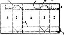
Translated fromKorean제1도는 겹쳐진 접합봉합부의 모퉁이 영역에 잡아뜯어서 개방하는 플랩구멍을 형성하기 위해서 완전 절단선과 절반 절단선을 가지는 팩용지의 평면도.1 is a plan view of a pack paper having a complete cut line and a half cut line to form a flap hole that is open by tearing open at a corner area of the overlapped seam.
제2도는 제1도에 도시된 배치의 부분도.FIG. 2 is a partial view of the arrangement shown in FIG.
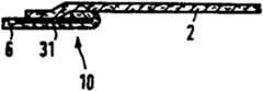
제3도는 벗겨낸 접합부를 가지는 제2도에 도시된 부분의 횡단면도.FIG. 3 is a cross sectional view of the portion shown in FIG. 2 with the stripped joint. FIG.
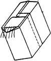
제4도는 제1도에서 3도에 따른 플랩구멍을 가진 팩의 사시도.4 is a perspective view of a pack with flap holes according to FIG. 1 in FIG.
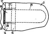
제5도는 접합봉합부의 중심 영역안에 플랩구멍을 형성하기 위해서 완전 절단선들과 절반 절단선들을 가지는 팩용지의 평면도.5 is a plan view of a pack paper having full cut lines and half cut lines to form a flap hole in the center region of the seam seal.
제6도는 접합봉합부의 중심 영역에 있어서의 제5도에 도시한 플랩구멍 배치의 부분도.Fig. 6 is a partial view of the flap hole arrangement shown in Fig. 5 in the center region of the joint sealing portion.
제7도는 불접착제를 가지는, 제6도에 도시된 접합봉합부의 횡단면도.FIG. 7 is a cross-sectional view of the junction suture shown in FIG. 6 with an adhesive.
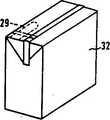
제8도는 제5도-제7도에 따르는 플랩구멍을 가지는 팩의 사시도.8 is a perspective view of a pack having flap holes according to FIGS. 5-7.
제9도-1l도는 여러가지 개방상태의 팩의 사시도.9-1-1 are perspective views of packs in various open states.
제12도는 유출구멍을 가지는 팩의 사시도.12 is a perspective view of a pack having an outlet hole.
제13도는 음용구멍을 가지는 팩의 사시도.13 is a perspective view of a pack having a drinking hole.
제14도와 15도는 각각 스폰구멍을 가지는 팩의 평면도 및 개략 사시도이다.14 and 15 are plan and schematic perspective views, respectively, of a pack having spawn holes.
* 도면의 주요부분에 대한 부호의 설명* Explanation of symbols for main parts of the drawings
1 : 팩 용지 2-6 : 팩면1: pack paper 2-6: pack side
8,9 : 완전 절단선 10 : 접합봉합부8,9: complete cutting line 10: joint seal
11,12,13 : 절반 절단선 14 : 제1접합부11,12,13: half cut line 14: first joint
15 : 제2접합부 16 : 테두리선15: second joint portion 16: border line
18 : 벗기는 탭 22,23,27.28 : 완전 절단선18:
24,25 : 절반 절단선 31 : 불접착제24,25: half cut line 31: non-adhesive
본 발명은, 접합봉합부에 잡아뜯어서 개방하는 플랩구멍이 있는 합성수지로 피복된 층상질로 구성되는 팩(pack)에 관한 것이다.The present invention relates to a pack composed of a layered material coated with a synthetic resin having flap holes to be pulled open to the joint sealing portion.
여러가지 형태의 플랩구멍을 가지는 팩이 알려져 있다. 이를테면 팩의 개방범위에 안쪽 스탬핑 또는 바깥쪽 스탬핑을 행하고, 그것을 다시 잡아뜯어서 개방하는 플랩에 의해 폐쇄하는 것이 알려져 있다. 그러나 팩과 일체로 되어있지 않은 이러한 플랩의 단점은, 방진뿐만 아니라 액체에 대해서도 밀봉된 포장 또는 기체 기밀 포장이 요구되는 민감한 제품의 경우에 불리하고, 특히 무균팩에 관하여서 층상질 본래의 전체면에 뻗어있는 내부피막이 구멍 영역에서 찢어져서 열리게 되므로서, 그러한 사정에 있어서는 충진상품의 품질의 저하를 초래할 수 있다는 것이다. 게다가 이러한 잡아뜯어서 개방하는 플랩과 이것을 팩에 고정하는데 필요한 방법은 많은 경비를 요한다.Packs with flap holes of various forms are known. It is known, for example, to make an inner stamping or an outer stamping on the opening of the pack and to close it by a flap which pulls it open again. However, the disadvantage of this flap, which is not integral with the pack, is disadvantageous in the case of sensitive products requiring sealed packaging or gas tight packaging for liquid as well as dustproof, in particular with respect to the sterile intact whole surface. Since the inner film extending to the torn open in the hole area, the quality of the packed product may be degraded in such circumstances. In addition, these flap openings and the methods required to secure them to the pack are expensive.
팩과 일체로 형성된 잡아뜯어서 개방하는 플랩은 또한 이미 개발되어 있다. 예를들면 유럽 특허출원 제36,116호는 빨대를 삽입할 수 있는 플랩구멍을 가진 액채팩을 설명하고 도시한다. 음용(飮用)빨대 구멍은 팩의 측부접합부 안에 일체화되고, 또 이것에 안쪽 및 바깥쪽 절단선에 의해 구획되어 있다. 그러나 원하는경우, 잡아뜯어 개방하는때에, 표면층이 층상질로 부터 느슨해져서 잘못된 개방을 방지하기 위해서, 피복된 접합부에 하나의 절단선을 설치할수도 있다. 이렇게 만들어진 플랩은 매우 짧고 비용이 많이드는 형상의 절단선을 사용한때에만 취급하기가 용이하다. 게다가 플랩구멍이 겹쳐진 접합봉합부에 있으므로 모서리 둘레의 보호를 필요로 하지 않는 제품류에만 사용할 수 있다. 따라서 그러한 플랩구멍은 무균팩에는 부적당하다.Open flaps, integral with the pack, have also been developed. European Patent Application No. 36,116, for example, describes and illustrates a liquid fan pack having a flap hole into which a straw can be inserted. The drinking straw hole is integrated in the side joint of the pack, and is partitioned by the inner and outer cutting lines. However, if desired, at the time of plucking open, one cut line may be provided at the coated joint to prevent the surface layer from loosening from the stratification and preventing false opening. The flaps thus made are easy to handle only when very short and costly cut lines are used. In addition, the flap-holes with overlapping joints can only be used for products that do not require protection around the edges. Such flap holes are therefore unsuitable for aseptic packs.
미합중국 특허 명세서 제 4,244,474호에는 다른 플랩구멍을 가진 팩이 알려져 있고, 이 경우에는 층상질의 지지재료에 서로 평행한 절단선에 의하여 플랩구멍을 형성할 수 있다. 상기의 플랩은 결국 원형의 구멍안으로 이동하지만, 이러한 구멍은, 절개선들 사이에 존재하는 평면과 마찬가지의 층상질이 절단되지 않은 층에 의해 여전히 덮여있다. 따라서 이러한 구멍은, 현존하는 층을 빨래로 관통할때 밖에 이용할 수 없고, 또한 이러한 목적을 위해서만 디자인 된다.In US Pat. No. 4,244,474, packs with different flap holes are known, in which case flap holes can be formed by cutting lines parallel to each other in the layered support material. The flap eventually moves into a circular hole, but this hole is still covered by a layer in which the layered material is not cut, similar to the plane existing between the incisions. These holes are therefore only available for washing through existing layers with laundry, and are also designed for this purpose only.
마지막으로 캐나다 특허 명세서 제 678,370호에는, 플랩구멍을 가진 팩이 기재되어 있고, 이 팩에서는 겹쳐진 접합봉합부에 관통하는 절개선과 이것에 연결되어 있는 구멍이 설치된 것에 의해. 구멍을 형성하기 위해 팩을 옆으로 잡아 뜯어 개방할 수 있다. 동시에 다른 팩 평면에 있는 V자형에 가까운 절개에 의해, 잡아뜯어질때 또한 그 구멍이 잡아뜯어지는 플랩에 의해서 함께 개방된다. 이러한 형태의 봉합장치는, 겹쳐진 접합봉합부에 의한, 둘레에 형성된 모서리 보호부릍 가지는 무균팩에 부적당한 것은 별개의 문제로 하고, 그밖에 상응하는 절단선을 겹쳐진 접합봉합부에 만들기 위해서도 역시 비용이 많이 드는 성형 절단이 필요하다.Finally, Canadian Patent Specification No. 678,370 describes a pack having a flap hole, in which the cut line penetrates the overlapped seam and the hole connected thereto. The pack can be pulled open to the side to form a hole. At the same time, by the incision close to the V-shape in the other pack planes, the hole is opened together by the flap when it is torn off. The sealing device of this type is another problem that it is unsuitable to the aseptic pack having the edge protection portion formed at the periphery by the overlapped seam, and is also expensive to make the corresponding cut line at the seam. Lifting molding cuts are necessary.
그러므로 본 발명의 목적은 겹쳐진 접합봉합부에 제어되지 않은 손상을 피하면서, 비용이 많이드는 성형절단을 사용함이 없이 간단하고 경제적인 또한 취급이 용이하고 쉬운 접합봉합부를 가진 합성수지로 피복된 층상질의 팩에 잡아 뜯어내는 플랩구멍을 제공하는 것이다.It is therefore an object of the present invention to provide a layered pack of synthetic resin coated with a simple, economical, easy-to-handle and easy-to-use joint seal without the use of costly molding cuts, while avoiding uncontrolled damage to the overlapped joint seals. To provide a flap hole to pry off.
이러한 과제를 해결하기 위해 본 발명에 따르면, 접합봉합부가 제1팩 표면의 길이방향으로 형성된 테두리선으로 부터, 접합봉합부에 의해 제1팩면에 연결된 제2팩면의 겹쳐진 모서리까지 연장한 제1접합부 안에, 제 1팩면의 절개로 인해 형성된 하나이상의 완전 절단선을 가지며, 제 1접합부에 인접한 제 2 접합부 안에, 완전 절단선에 연장하여 하나이상의 점선을 가지고, 이 점선이 제2접합부를 지나서, 팩의 내용물과 접촉하는 제1팩면의 범위에까지 연장하므로서 상기의 목적이 성취된다. 본 발명 수단에 따르면, 만들기가 간단하고 확실히 취급할수 있는 플랩구멍을 제공한다. 그것은 또한 팩의 내용물과 접촉하는 내부피막에 손상 및 약화가 발생하지 않게한다.In order to solve this problem, according to the present invention, the first joint portion extending from the border line formed in the longitudinal direction of the first pack surface to the overlapping edge of the second pack surface connected to the first pack surface by the joint seal portion In the at least one complete cut line formed due to the incision of the first pack surface, and in a second joint adjacent the first joint, having at least one dotted line extending to the full cut line, the dotted line past the second joint, The above object is achieved by extending to the range of the first pack surface in contact with the contents of the. According to the means of the present invention, there is provided a flap hole that is simple to make and can be handled reliably. It also prevents damage and weakening of the inner coating that comes into contact with the contents of the pack.
특정의 실시예에 있어서, 하나 또는 복수의 점선이, 제1팩면의 단일층이나 다층의 벽을 부분적으로만 절단한 절반 절단선에 의해 형성된다. 또한 절반 절단 대신에, 구멍 뚫기가 용이한 것을 사용할 수 있는 것도 말할나위가 없다. 한편으로, 플랩구멍의 취급을 개선하기 위해서, 다른 한편으로는 팩에 필요한 밀봉성을 보증하기 위해서 본 발명의 또다른 특징에 따라서, 하나 또는 복수의 완전 절단선을 가지는 제1접합부가, 하나 또는 복수의 절반 절단선을 가지는 제2접합부보다 더 넓게 형성된다.In certain embodiments, one or more dashed lines are formed by half cut lines that only partially cut a single layer or multilayer wall of the first pack surface. It goes without saying that instead of half cutting, one that can be easily drilled can be used. On the one hand, in order to improve the handling of the flap hole, on the other hand, in order to ensure the sealing properties required for the pack, on the other hand, according to another feature of the present invention, one or more first joining portions having one or more complete cutting lines It is formed wider than the second junction having a plurality of half cut lines.
본 발명의 또다른 특징에 따라서, 제1팩면과 면하는 제2팩면의 상단부에, 하나 또는 복수의 완전 절단선에 의해 구획된 벗기는 탭(tap)을 형성하는 접합봉합부의 범위에, 이를테면 0-3mm의 약간의 간격을 두고서 제1팩면의 길이방향으로 형성된 테두리선에 대해 평행하게 형성한 절반 절단선을 배치하면, 벗기는 탭을 매우 용이하게 잡을수 있고, 또 이러한 벗기는 탭과 그것에 이어진 점선에 걸쳐서 구멍이 형성되므로 팩을 더욱 쉽게 개방할 수 있다.According to another feature of the invention, in the range of a joint seal which forms a peeling tap partitioned by one or a plurality of complete cutting lines at the upper end of the second pack surface facing the first pack surface, for example 0-. By arranging the half cut lines formed parallel to the edges formed in the longitudinal direction of the first pack surface with a slight gap of 3 mm, it is very easy to grasp the peeling tabs, and the holes across the stripping tabs and the dotted lines that follow. This formation makes it easier to open the pack.
테두리선에 평행하게 연장한 점선 대신에, 하나 또는 복수의 완전 절단선 또는 하나 또는 복수의 절반 절단선에 의해 구획된 접합봉합부의 범위에, 제1팩면의 아래쪽과 제2팩면의 상단부와 더불어 접합봉합부의 겹쳐진 모서리의 아래쪽과의 사이에 불접착제가 피복될 수 있다. 또한 이런 경우에도, 플랩구멍이 벗기는 탭에 의해서 또 내부 피막과 모서리 보호를 잡아뜯어서 파열시키므로서 쉽게 개방될 수 있으므로 내용물을 포함하는 공간을 쉽게 얻을 수 있다.Instead of the dashed line extending parallel to the rim, the joint is joined together with the lower end of the first pack face and the upper end of the second pack face, in the range of the joint seal segmented by one or more complete cut lines or one or more half cut lines. An adhesive can be coated between the bottom of the overlapped edge of the seam. Also in such a case, since the flap hole can be easily opened by the tab which peels off and tears and tears the inner film and the edge protection, the space including the contents can be easily obtained.
단일의 완전 절단선에 의해 구획된 벗기는 탭이 접합봉합부의 모서리 범위 또는 그밖에 접합봉합부의 중앙범위에 배치될 수 있다. 이런 경우에는, 벗기는 탭을 구획하는 범위가, 서로 간격을 두고서 형성된 두개의 완전 절단선에 의하여 형성된다. 이때, 하나 또는 복수의 완전 절단선에 따라, 점선을 예를들면 팩 둘레에 형성한 분리스트립을 점선사이에 형성하도록 또는 양쪽의 완전 절단선을 공통의 절반 절단선에 의해 서로 연결되는 방식으로 부속할 수 있다.Stripping tabs partitioned by a single complete cut line may be placed in the corner range of the seam or else in the center range of the seam. In this case, the extent of partitioning the stripping tab is formed by two complete cut lines formed at intervals from each other. At this time, according to one or a plurality of full cut lines, the dotted line is formed in such a manner that a separate strip formed around the pack is formed between the dotted lines or both full cut lines are connected to each other by a common half cut line. can do.
따라서, 하나 또는 복수의 완전 절단선에서 시작하여, 이에 상응하여 바깥쪽으로 뻗치는 과정에 있어서, 팩에 스폰구멍 및 음용빨대 및 유출 및 음용구멍이 형성될 수 있다. 이때, 점선이 완전 절단선의 후방으로 끝이 가늘어지고 구멍선단이 팩의 측면에 접하는 접는 삼각형의 범위에까지 연장하는 것이 편리하다. 이러한 타입의 팩은 쉽게 개방될 수 있고, 팩을 열때, 전혀 내용물이 엎질러지지 않는다. 왜냐하면, 팩은 열린때에 팩의 바닥에서 평평면 위에 완전히 세워지고 동시에 접혀진 크기를 유지하면서 세워져서, 즉, 내용물을 포함하는 공간이 변형되지 않기 때문이다. 소위 러그(lug)타입의 팩에서는, 모퉁이 접합부만을 일으켜 세우면 된다.Thus, in the process of starting at one or a plurality of complete cut lines and correspondingly extending outwards, spawning holes and drinking straws and outflowing and drinking holes may be formed in the pack. At this time, it is convenient for the dotted line to extend to the range of the folding triangle where the tip is tapered to the rear of the complete cutting line and the hole tip is in contact with the side of the pack. Packs of this type can be easily opened and do not spill any contents when opening the pack. This is because the pack is erected on a flat surface at the bottom of the pack when it is opened and at the same time maintaining its folded size, ie the space containing the contents is not deformed. In the so-called lug pack, only the corner joints can be raised.
팩에 플랩구멍을 형성하는 적절한 방법이 본 발명에 특히 중요하고 이 방법에 있어서 하나 또는 복수의 완전 절단선과 하나 또는 복수의 절반 절단선을 팩 평면에 배치하는 작업이 이미 피복된 층상질의 스탬핑,홈파기, 프린팅과 함께 단일 작업으로 팩 표면에 형성된다.A suitable method of forming flap holes in the pack is of particular importance in the present invention and in this method a layered stamping, groove already coated with the work of placing one or a plurality of complete cut lines and one or a plurality of half cut lines in the pack plane. It is formed on the pack surface in a single operation with digging and printing.
이렇게하여, 플랩구멍 또는 그것에 필요한 완전 절단선 및 절반 절단선이 지지필름 단면에 가압 스탬핑으로 매우 쉽게 만들어질 수 있고, 그때 용지를 생산하는데 어떤 복잡한 성형 절단도 필요없이, 이것은 리일 절단기 및 수직 절단기와 횡 절단기에 의해 수행될 수 있는 것이다.In this way, the flap hole or the complete cutting line and half cutting line necessary for it can be made very easily by pressure stamping on the end face of the supporting film, and then without the need for any complicated molding cutting to produce paper, It can be performed by the transverse cutter.
제1도는 팩을 만드는 층상질 용지를 도시한다. 알려진 대로 층상질은 외부 합성수지 피막, 판지 또는 유사한 것으로 구성된 지지재료, 내층 필름, 알루미늄층 및 내부 합성수지 피막으로 구성된다. 용지(1)는 팩면(2,3,4,5,6)을 가지며 도면에 있어서, 팩면(2)는 제1팩면을 가리키고 팩면(6)은 제2팩면을 가리킨다. 용지(l)가 용지안의 일점쇄선(7)을 따라 접혀진후에 제3도에 도시된 것처럼 제1팩면(2)과 제2팩면(6)이겹쳐진 접합부에 의해서 서로 연결될 수 있다. 이것이 벗겨진 접합부이다. 즉 제2팩면(6)의 자유단부가 안쪽으로 접혀지고 그러므로 접합부 둘레를 따라 모서리가 보호된다. 완전 절단선(8)과 다른 완전 절단선(9)과 그들의 각각에 이웃한 점선들의 형태의 절반 절단선(11,12)의 형태대로 팩면(2)에 배치되어 있다. 다른점선(13)이 팩면(5,6)에 제공될 수 있으며 그 목적은 하기에 더 상세히 설명된다.1 shows a layered paper making a pack. As is known, the layered material consists of a support material consisting of an outer plastic film, cardboard or the like, an inner film, an aluminum layer and an inner plastic film. The paper 1 has pack faces 2, 3, 4, 5, 6 and in the drawing, the
제2도에 나타난 것처럼, 완전 절단선(8)이 접합봉합부(10)의 제1접합부(14)까지 연장되고, 그때 제1접합부(14)는 제2접합부(15)보다 폭이 넓고, 그 제2접합부까지 절반 절단선(11)이 연장하여 마침내 팩면(2,3)까지 연장되어 있다. 완전 절단선(8)은 테두리선(16)에 평행하고 팩면(2)의 테두리선(17)에 대하여 수직이다. 완전 절단선(8)은 접합봉합부(10)안에 벗기는 탭(18)을 형성하고, 그 아래에 팩면(6)에서 더 쉽게 절개하기 위해, 테두리선(17)에 평행하게 절반 절단선(19)형태의 점선이 테두리선(17)으로부터 약 3mm정도의 간격으로 형성되어 있다. 이러한 형태의 플랩구멍을 가진 팩(21)이 제4도에 도시되어 있다. 이 경우, 상기 구멍은 벗기는 탭(18)에 의해 얻어질수 있고 팩면(6)이 절개될때 하기에 자세히 설명한 것처럼 절반 절단선(11)을 따라 절개된다.As shown in FIG. 2, the complete cutting line 8 extends to the
제5도-8도에 도시된 실시예의 경우, 용지(1)에 있어서, 접합부의 중앙부 근처에 두개의 완전 절단선(22,23)이 형성되고, 이 완전 절단선에는 절반 절단선(24,25)이 분리 스트립(26)을 형성하여 팩둘레에 형성되어, 이는 예를들면 냉동팩에 적당한 것이다.In the embodiment shown in Figs. 5-8, in the paper 1, two
제5도에는 또다른 실시예가 도시되어 있는데, 두개의 완전 절단선(27,28)이 일정한 거리를 두고 서로에 대하여 평행하게 배열되어 있고, 공통의 절반 절단선(29)에 의하여 서로 연결되어 있다. 이러한 배열은 제6도에 더 상세히 도시되어 있다.Another embodiment is shown in FIG. 5, where two
이 경우도 완전 절단선(27,28)은 제1접합부(14)에 연장하고, 또한 점선(29)은 제2접합부(15) 및 내용물과 접촉하는 팩면(2)에 연장하고 있다. 이 경우에, 제2팩면(6)의 상단부와, 이것에 대향하는 팩면(2)의 아래쪽과 나란하게 접합봉합부의 겹쳐진 모서리와의 사이에, 불접착제(31)가 피복되어 있고, 그 표면은, 완전 절단선(27,28)과 테두리선(17)에 의해 형성된 영역보다 약간 더 크다.Also in this case, the
이러한 형태의 플랩구멍을 가진 팩(32)이 제8도에 도시되어 있다. 이러한 형태의 구멍은 쏟아부을수 있는 분말상 물질에 적합하다.A pack 32 with this type of flap hole is shown in FIG. This type of hole is suitable for pourable powdery materials.
완전 절단선이 전체 층상 구조를 절단하는 절단선인 반면에, 절반 절단선은 단지 외부 합성수지 피막과 지지재료만을 절단하고 다른 층들은 그대로 남겨둔다.The complete cut line is the cut line that cuts the entire layered structure, while the half cut line only cuts the outer plastic film and support material, leaving the other layers intact.
제9도-11도는 제각기 팩 구멍이 어떠한 순서로 만들어지는지를 도시한다. 여기에서 플랩구멍의 배치에 있어서, 팩 상단 띠접합부(33)의 영역에서, 접혀진 삼각형(34)에 의해 형성된 팩 돌기부를 먼저 수평위치로 저친다. 그리고나서 벗기는 탭(18)을 붙잡아 위로 저친다. 이때, 그 아래에 있는 제2팩면(6)의 층이, 모서리 보호를 파열하므로서 정확히 조절된 방법으로 잡아뜯고(제10도), 점선을 따라서 잡아뜯으므로 제11도에 도시된 바와같이 구멍이 만들어진다. 상기의 도면들에 도시된 것처럼 다른 점선을 만들어서 예를들면 제12도에 따른 유출구멍과 제13도에 따른 음용구멍과 제14도 및 15도에 따른 스폰구멍 같은 다른 구멍들을 제공할 수도 있다.9-11 show in what order the pack holes are made, respectively. Here, in the arrangement of the flap holes, in the region of the pack top strip
제11도에 도시된 것처럼, 팩 상단 띠접합부의 밀봉 접합 모서리에 의해 점선을 직접 형성할수도 있다. 이와같이 큰 구멍을 얻으려면, 점선들이 완전 절단선에서 시작하여, 바깥쪽으로 넓어져서 다시 정면을 향해서 가늘어져서 한점으로 모아지지 않으면 안된다. 이때, 구멍끝이 겹쳐진 삼각형(34)의 영역으로 확장되는 것이 중요하다. 왜냐하면 이와같이해서 팩에 담겨진 제품을 안전하게 유출시키는 것이 가능하기 때문이다.As shown in FIG. 11, a dotted line may be directly formed by the sealing joint edge of the pack top strip junction. In order to obtain such a large hole, the dashed lines must start from a complete cut line, widen outward and taper back to the front and be collected in one point. At this time, it is important that the end of the hole extends to the area of the overlapped triangle 34. Because in this way it is possible to safely spill the product contained in the pack.
완전 절단선들과 절반 절단선의 배치는, 가압 스탬핑의 필름시이트 절단에 의해, 이미 피복된 층상재료의 홈파기. 프린팅 및 스탬핑과 함께 단일 작업으로 한번에 실행되는 것이 적합한 것이다.The arrangement of the complete cut lines and the half cut lines is the grooving of the layered material already covered by the film sheet cutting of the pressure stamping. It is appropriate to run in a single job with printing and stamping at once.
또한 테두리선(17)에 대해 평행하게 되어있는 점선(29)을 더욱 안쪽으로 향하게하여, 불접착제와 조합해서 배치할수도 있으므로, 연결해야할 결합이, 접속되어 있지않은 접합봉합부에서 절반의 강도로 되므로서, 잡아뜯는 작업이 쉽게 이루어지는 것은 물론이다.In addition, since the dotted
Claims (13)
Translated fromKoreanPriority Applications (1)
| Application Number | Priority Date | Filing Date | Title |
|---|---|---|---|
| KR1019850008390AKR900007284B1 (en) | 1985-11-09 | 1985-11-09 | Tear-open plap orifice on pack consisting of plastic-coated laminated material with a folded round fillet-sean closure and a process for producing the tearopen flap orifice |
Applications Claiming Priority (1)
| Application Number | Priority Date | Filing Date | Title |
|---|---|---|---|
| KR1019850008390AKR900007284B1 (en) | 1985-11-09 | 1985-11-09 | Tear-open plap orifice on pack consisting of plastic-coated laminated material with a folded round fillet-sean closure and a process for producing the tearopen flap orifice |
Publications (2)
| Publication Number | Publication Date |
|---|---|
| KR870004887A KR870004887A (en) | 1987-06-02 |
| KR900007284B1true KR900007284B1 (en) | 1990-10-08 |
Family
ID=19243606
Family Applications (1)
| Application Number | Title | Priority Date | Filing Date |
|---|---|---|---|
| KR1019850008390AExpiredKR900007284B1 (en) | 1985-11-09 | 1985-11-09 | Tear-open plap orifice on pack consisting of plastic-coated laminated material with a folded round fillet-sean closure and a process for producing the tearopen flap orifice |
Country Status (1)
| Country | Link |
|---|---|
| KR (1) | KR900007284B1 (en) |
- 1985
- 1985-11-09KRKR1019850008390Apatent/KR900007284B1/ennot_activeExpired
Also Published As
| Publication number | Publication date |
|---|---|
| KR870004887A (en) | 1987-06-02 |
Similar Documents
| Publication | Publication Date | Title |
|---|---|---|
| US5125529A (en) | Thermoplastic container opened by partially peeling back a multi-layered top which has been heat-sealed to its edge, and film for multi-layer tops | |
| US4572377A (en) | Packaging structure | |
| US4735335A (en) | Composite band for lids for thermoplastic containers | |
| US6659645B1 (en) | Stand-up bag | |
| US5836697A (en) | Opening device for flexible containers, container provided with such a device and application method thereof | |
| CA1232248A (en) | Tubular container having a tear opening means | |
| US4715528A (en) | Reclosable opening arrangement on a packing container | |
| US4566928A (en) | Method of manufacturing packing container having tear-up opening arrangement | |
| US5620550A (en) | Packaging material with an opening arrangement and a method of producing same | |
| US12258185B2 (en) | Paper-based or paperboard-based container and related methods | |
| US4792069A (en) | Pouring edge on packing containers | |
| JPS58125443A (en) | Device concerning packing vessel | |
| EP0227736B1 (en) | A tape tab for opening a container | |
| CA2263923A1 (en) | Package for pourable goods | |
| JPH02296656A (en) | Closing device with zipper for thermo-molded package | |
| US3620439A (en) | Severable carton with sterile edge | |
| US4546884A (en) | Tear strip end closure on liquid tight carton | |
| KR102501281B1 (en) | Container sealing body | |
| US4666044A (en) | Tear-open flap orifice on packs consisting of plastic-coated laminated material with a folded-round fillet-seam closure and a process for producing the tear-open flap orifice | |
| US4318479A (en) | Liquid container with straw opening means | |
| KR900007284B1 (en) | Tear-open plap orifice on pack consisting of plastic-coated laminated material with a folded round fillet-sean closure and a process for producing the tearopen flap orifice | |
| US20180305102A1 (en) | Sealing Foil with Pull Tab | |
| EP3386883B1 (en) | Food package having a reclosable opening feature and method of opening, removing a food product and reclosing a reclosable food package | |
| US5228616A (en) | Package container provided with a strip-type opening arrangement | |
| US4796760A (en) | Packing container provided with opening arrangement |
Legal Events
| Date | Code | Title | Description |
|---|---|---|---|
| PA0109 | Patent application | St.27 status event code:A-0-1-A10-A12-nap-PA0109 | |
| R17-X000 | Change to representative recorded | St.27 status event code:A-3-3-R10-R17-oth-X000 | |
| P11-X000 | Amendment of application requested | St.27 status event code:A-2-2-P10-P11-nap-X000 | |
| P13-X000 | Application amended | St.27 status event code:A-2-2-P10-P13-nap-X000 | |
| A201 | Request for examination | ||
| PA0201 | Request for examination | St.27 status event code:A-1-2-D10-D11-exm-PA0201 | |
| PG1501 | Laying open of application | St.27 status event code:A-1-1-Q10-Q12-nap-PG1501 | |
| R17-X000 | Change to representative recorded | St.27 status event code:A-3-3-R10-R17-oth-X000 | |
| E902 | Notification of reason for refusal | ||
| PE0902 | Notice of grounds for rejection | St.27 status event code:A-1-2-D10-D21-exm-PE0902 | |
| T11-X000 | Administrative time limit extension requested | St.27 status event code:U-3-3-T10-T11-oth-X000 | |
| T11-X000 | Administrative time limit extension requested | St.27 status event code:U-3-3-T10-T11-oth-X000 | |
| T11-X000 | Administrative time limit extension requested | St.27 status event code:U-3-3-T10-T11-oth-X000 | |
| T11-X000 | Administrative time limit extension requested | St.27 status event code:U-3-3-T10-T11-oth-X000 | |
| P11-X000 | Amendment of application requested | St.27 status event code:A-2-2-P10-P11-nap-X000 | |
| P13-X000 | Application amended | St.27 status event code:A-2-2-P10-P13-nap-X000 | |
| G160 | Decision to publish patent application | ||
| PG1605 | Publication of application before grant of patent | St.27 status event code:A-2-2-Q10-Q13-nap-PG1605 | |
| E701 | Decision to grant or registration of patent right | ||
| PE0701 | Decision of registration | St.27 status event code:A-1-2-D10-D22-exm-PE0701 | |
| GRNT | Written decision to grant | ||
| PR0701 | Registration of establishment | St.27 status event code:A-2-4-F10-F11-exm-PR0701 | |
| PR1002 | Payment of registration fee | St.27 status event code:A-2-2-U10-U11-oth-PR1002 Fee payment year number:1 | |
| LAPS | Lapse due to unpaid annual fee | ||
| PC1903 | Unpaid annual fee | St.27 status event code:A-4-4-U10-U13-oth-PC1903 Not in force date:19931009 Payment event data comment text:Termination Category : DEFAULT_OF_REGISTRATION_FEE | |
| PC1903 | Unpaid annual fee | St.27 status event code:N-4-6-H10-H13-oth-PC1903 Ip right cessation event data comment text:Termination Category : DEFAULT_OF_REGISTRATION_FEE Not in force date:19931009 | |
| P22-X000 | Classification modified | St.27 status event code:A-4-4-P10-P22-nap-X000 |