KR900007030B1 - Offset qudra phase differential p.s.k. modem device - Google Patents
Offset qudra phase differential p.s.k. modem deviceDownload PDFInfo
- Publication number
- KR900007030B1 KR900007030B1KR1019860004894AKR860004894AKR900007030B1KR 900007030 B1KR900007030 B1KR 900007030B1KR 1019860004894 AKR1019860004894 AKR 1019860004894AKR 860004894 AKR860004894 AKR 860004894AKR 900007030 B1KR900007030 B1KR 900007030B1
- Authority
- KR
- South Korea
- Prior art keywords
- signal
- reproducing
- recording
- digital signal
- output
- Prior art date
- Legal status (The legal status is an assumption and is not a legal conclusion. Google has not performed a legal analysis and makes no representation as to the accuracy of the status listed.)
- Expired
Links
Images


Classifications
- H—ELECTRICITY
- H03—ELECTRONIC CIRCUITRY
- H03D—DEMODULATION OR TRANSFERENCE OF MODULATION FROM ONE CARRIER TO ANOTHER
- H03D9/00—Demodulation or transference of modulation of modulated electromagnetic waves
- H—ELECTRICITY
- H04—ELECTRIC COMMUNICATION TECHNIQUE
- H04L—TRANSMISSION OF DIGITAL INFORMATION, e.g. TELEGRAPHIC COMMUNICATION
- H04L27/00—Modulated-carrier systems
- H04L27/18—Phase-modulated carrier systems, i.e. using phase-shift keying
- H04L27/20—Modulator circuits; Transmitter circuits
- H04L27/2032—Modulator circuits; Transmitter circuits for discrete phase modulation, e.g. in which the phase of the carrier is modulated in a nominally instantaneous manner
- H04L27/2053—Modulator circuits; Transmitter circuits for discrete phase modulation, e.g. in which the phase of the carrier is modulated in a nominally instantaneous manner using more than one carrier, e.g. carriers with different phases
- H04L27/206—Modulator circuits; Transmitter circuits for discrete phase modulation, e.g. in which the phase of the carrier is modulated in a nominally instantaneous manner using more than one carrier, e.g. carriers with different phases using a pair of orthogonal carriers, e.g. quadrature carriers
- H04L27/2067—Modulator circuits; Transmitter circuits for discrete phase modulation, e.g. in which the phase of the carrier is modulated in a nominally instantaneous manner using more than one carrier, e.g. carriers with different phases using a pair of orthogonal carriers, e.g. quadrature carriers with more than two phase states
- H04L27/2078—Modulator circuits; Transmitter circuits for discrete phase modulation, e.g. in which the phase of the carrier is modulated in a nominally instantaneous manner using more than one carrier, e.g. carriers with different phases using a pair of orthogonal carriers, e.g. quadrature carriers with more than two phase states in which the phase change per symbol period is constrained
- H04L27/2082—Modulator circuits; Transmitter circuits for discrete phase modulation, e.g. in which the phase of the carrier is modulated in a nominally instantaneous manner using more than one carrier, e.g. carriers with different phases using a pair of orthogonal carriers, e.g. quadrature carriers with more than two phase states in which the phase change per symbol period is constrained for offset or staggered quadrature phase shift keying
- G—PHYSICS
- G11—INFORMATION STORAGE
- G11B—INFORMATION STORAGE BASED ON RELATIVE MOVEMENT BETWEEN RECORD CARRIER AND TRANSDUCER
- G11B20/00—Signal processing not specific to the method of recording or reproducing; Circuits therefor
- G11B20/10—Digital recording or reproducing
- H—ELECTRICITY
- H04—ELECTRIC COMMUNICATION TECHNIQUE
- H04L—TRANSMISSION OF DIGITAL INFORMATION, e.g. TELEGRAPHIC COMMUNICATION
- H04L27/00—Modulated-carrier systems
- H04L27/18—Phase-modulated carrier systems, i.e. using phase-shift keying
- H04L27/22—Demodulator circuits; Receiver circuits
- H04L27/227—Demodulator circuits; Receiver circuits using coherent demodulation
Landscapes
- Engineering & Computer Science (AREA)
- Signal Processing (AREA)
- Computer Networks & Wireless Communication (AREA)
- Physics & Mathematics (AREA)
- Electromagnetism (AREA)
- Power Engineering (AREA)
- Digital Transmission Methods That Use Modulated Carrier Waves (AREA)
- Signal Processing For Digital Recording And Reproducing (AREA)
Abstract
Translated fromKoreanDescription
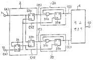
Translated fromKorean제1도 a는 본 발명의 오프셋 4상 차동 PSK변조기의 1실시예를 도시한 회로도.1 is a circuit diagram showing one embodiment of an offset four-phase differential PSK modulator of the present invention.
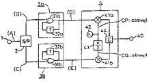
제1도 b는 본 발명의 오프셋 4상 차동 PSK복조기의 1실시예를 도시한 회로도.1 is a circuit diagram showing one embodiment of an offset four-phase differential PSK demodulator of the present invention.
제2도는 제1도 a와 제1도 b에 도시한 오프셋 4상 차동 PSK 변복조기의 주요부분에서 실행되는 동작을 설명하는 파형도.FIG. 2 is a waveform diagram illustrating the operation performed in the main part of the offset four-phase differential PSK modulator shown in FIGS. 1A and 1B.
제3도는 제1도 a에 도시된 오프셋 4상 차동 PSK 변조기의 주요부분의 1구성예를 도시한 회로도.FIG. 3 is a circuit diagram showing one configuration example of main parts of the offset four-phase differential PSK modulator shown in FIG.
제4도는 제3도에 도시된 회로구성의 주요부분에서의 동작을 설명하는 파형도.FIG. 4 is a waveform diagram illustrating the operation in the main part of the circuit arrangement shown in FIG.
제5도는 제1도 b에 도시된 오프셋 4상 차동 PSK 복조기의 주요부분의 1구성예를 도시한 회로도.FIG. 5 is a circuit diagram showing one configuration example of main parts of the offset four-phase differential PSK demodulator shown in FIG.
제6도는 제5도에 도시된 회로구성의 주요부분에서의 동작을 설명하는 파형도.FIG. 6 is a waveform diagram illustrating the operation in the main part of the circuit configuration shown in FIG.
제7도는 오프셋 4상 차동 PSK 변복조기를 디지탈 오디오 다층 자기기록재생장치에 적용한 경우의 1예로서 본 발명의 다른 실시예의 블럭도.7 is a block diagram of another embodiment of the present invention as an example in which an offset four-phase differential PSK modulator is applied to a digital audio multilayer magnetic recording and reproducing apparatus.
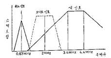
제8도는 제7도의 실시예에 있어서 자기기록매체에 기록되는 디지탈 오디오 신호와 비디오신호의 주파수특성을 도시한 그래프.8 is a graph showing the frequency characteristics of a digital audio signal and a video signal recorded on a magnetic recording medium in the embodiment of FIG.
제9도는 오디오 헤드의 특성에서 기록전류와 재생출력 레벨사이의 관계를 도시한 그래프.9 is a graph showing the relationship between the recording current and the reproduction output level in the characteristics of the audio head.
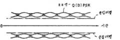
제10도는 오프셋 Q(D) PSK 변조파와 QPSK변조파의 포락선을 도시한 파형도.10 is a waveform diagram showing an envelope of an offset Q (D) PSK modulated wave and a QPSK modulated wave.
제11도는 오프셋 Q(D) PSK변조파의 스팩트럼을 도시한 그래프.11 is a graph showing the spectrum of an offset Q (D) PSK modulated wave.
제12도는 제7도의 실시예에서 디지탈 오디오 기록측에 배치되는 BPF(123)의 주파수 특성을 도시한 그래프.FIG. 12 is a graph showing the frequency characteristics of the
제13도는 제7도의 실시예에서 디지탈 오디오 기록측에 배치되는 리미터(124)의 1실시예를 도시한 회로도.FIG. 13 is a circuit diagram showing one embodiment of a
제14도는 제7도에 도시된 리미터(124)의 다른 실시예를 도시한 회로도.FIG. 14 is a circuit diagram showing another embodiment of the
본 발명은 일반적으로 자기기록재생방법 및 장치에 관한 것으로, 특히 기록되는 오디오 신호와 비디오 신호사이의 간섭을 방지하기 위해 선택형 변조 및 심층기록방식을 이용하는 비디오 테이프 레코더(VTR)용오디오 신호의 디지탈화에 관한 것이다.BACKGROUND OF THE
VTR시스템에서 오디오 신호와 비디오 신호를 기록하기 위한 다층 기록방법을 사용하는 것이 알려져 있다. 이것에 관해서는 미우라등의 IEEE Transactions on Consumer Electronics, Vol.CE-30,NO.3,1984.8,pgs.360∼369에 기재되어 있다. 이 논문은 제1도 및 제2도에서 명확하게 도시한 바와같이, 서로 다른애지머스각도를 갖는 비디오 헤드와 오디오 헤드를 분리하기 위해, 비디오 신호는 자기층의 표면층부위에기록되고, FM오디오신호는 심층부위에 기록된다. 재생모드에서, 비디오신호와 FM 오디오 신호는 애지머스손실효과의 도움으로 각각 재생되고 있다. 그러나 양신호는 미우라등의 방식에서 아날로그 신호로서 자기매체위에 기록된다.It is known to use a multilayer recording method for recording audio and video signals in a VTR system. This is described in IEEE Transactions on Consumer Electronics, Vol. CE-30, NO. 3, 1984.8, pgs. 360 to 369 to Miura et al. In this paper, as clearly shown in FIGS. 1 and 2, in order to separate the video head and the audio head having different azimuth angles, the video signal is recorded on the surface layer portion of the magnetic layer, and the FM audio signal Is recorded deeper. In the playback mode, the video signal and the FM audio signal are reproduced respectively with the aid of the azimuth loss effect. However, both signals are recorded on the magnetic medium as analog signals in Miura et al.
비디오신호와 오디오신호 양쪽을 디지탈 신호로서 자기 테이프위에 기록하는 것을 실행하기 위해서는 수년을 결쳐서 많은 노력을 해왔다. 이러한 노력은 크기와 표준 오디오 카세트에 필적하는 자기 테이프위의비디오신호와 오디오신호의 실현에 이르렀다. 그러나, 디지탈 오디오 신호와 비디오신호를 중첩하기 위해서는 오디오 신호의 디지탈 특성에 따른 간섭을 갖는 이들 신호사이의 간섭을 방지할 필요가 있다. 이것에 관해서, 애지머스 손실효과를 이용하여 비디오신호를 중첩시킨다 하더라도, 종래의 디지탈 오디오신호의 베이스 밴드변조를 채용한다면, 디지탈 오디오 베이스 밴드신호의 스펙트럼을 변환된 색신호로 분리하는 것은불가능하게 된다.Many years have been spent trying to record both video and audio signals as digital signals on magnetic tape. This effort has led to the realization of video and audio signals on magnetic tape comparable in size and standard audio cassettes. However, in order to superimpose the digital audio signal and the video signal, it is necessary to prevent the interference between these signals having interference according to the digital characteristics of the audio signal. On the other hand, even if the video signal is superimposed using the azimuth loss effect, if the baseband modulation of the conventional digital audio signal is adopted, it is impossible to separate the spectrum of the digital audio baseband signal into the converted color signal.
디지탈 라디오 통신분야에 있어서, 비교적 협대역 전송이 가능하다는 것과 복조기의 구성이 간단하다는장점이 있기 때문에 4상 차동 위상 변조방식(QDPSK SISTEM)이 널리 사용되고 있다. 그러나 그러한QDPSK 방식에서는 정보가 비선형 체널을 통과하므로 대역폭이 넓어지며, 또한 부호 에러율 특성이 저하하게 된다. 이러한 것들은 대역폭이 제한되어 있으며 반송파 전력 대 잡음 전력비(C/N)올 너무 크게 잡을수 없는 위성 통신이나 이동 통신등을 위한 송신기에서 해결해야하는 중대한 문제이다.In the field of digital radio communication, the four-phase differential phase modulation method (QDPSK SISTEM) is widely used because of the advantages of relatively narrow band transmission and simple demodulator configuration. However, in such a QDPSK scheme, since the information passes through the nonlinear channel, the bandwidth becomes wider and the code error rate characteristic is degraded. These are significant problems that need to be addressed in transmitters for satellite or mobile communications where bandwidth is limited and carrier power-to-noise power ratios (C / N) cannot be too large.
상기의 관점에서, 오늘날에는 오프셋 QPSK방식이 관심을 끈다. 이 방식은 H.Suzuki등에 의한"Fundamental Properties of Narrowband Digital Angle Modulations"(Shingaku Giho,CS-81-51,1981), R.K.Kwan에 의한 "The Effects of Filtering and Limiting A Double Binary PSK Signal"(IEEE Trans.on AES,1986,7)라는 제목의 문헌에서 다루고 있다. 이 방식에 의하면, 동상(R)채널과 직교(Q)채널의 데이터의 부호 변화점이 서로 1/2데이터 주기만큼 어긋나도록 변조되므로. 변조파의 포락선이제로 크로싱과는 무관하며, 비선형 체널을 통하는 데이터의 경로에 따라서 대역이 그렇게 확대되지는 않는다. 또, S.A.Rhodes에 의한 "Effects of Hard Limiting on Band-Limited Transmissions withConventional and offset QPSK Modulation"(IEEE National Telecommunication Conference,1972)라는제목의 문헌에서도 알 수 있다.In view of the above, the offset QPSK scheme is of interest today. This method is described in "Fundamental Properties of Narrowband Digital Angle Modulations" by H. Suzuki et al. (Shingaku Giho, CS-81-51,1981), "The Effects of Filtering and Limiting A Double Binary PSK Signal" by RKKwan (IEEE Trans .on AES, 1986, 7). According to this method, since the code change points of the data of the in-phase (R) channel and the orthogonal (Q) channel are shifted from each other by 1/2 data period. The envelope of the modulating wave is now independent of crossing, and the band does not extend so much along the path of the data through the nonlinear channel. It is also found in the document entitled "Effects of Hard Limiting on Band-Limited Transmissions with Conventional and offset QPSK Modulation" by S.A. Rhodes (IEEE National Telecommunication Conference, 1972).
그러나, 그러한 오프셋 QPSK방식에서는 종래의 QPSK방식에 사용되어온 차동 부호 및 복호방식을 사용하는 것이 불가능하여 복조기측에서 절대 위상의 검출이 필요하였다.However, in such an offset QPSK method, it is impossible to use the differential code and decoding method used in the conventional QPSK method, and thus the absolute phase detection is required on the demodulator side.
본 발명의 목적은 디지탈 정보를 기록재생하는 데 적합한 오프셋 4상 차동 PSK 변복조기가 설치된 정보기록재생방법 및 장치를 제공하는 것이다.An object of the present invention is to provide an information recording and reproducing method and apparatus provided with an offset four-phase differential PSK modulator suitable for recording and reproducing digital information.
본 발명은 비디오신호와 디지탈 오디오신호를 자기적으로 기록할 수 있는 정보기록재생방법 및 장치로서,상기 오프셋 4상 차동 PSK변조기가 디지탈 오디오 기록 라인에서 변조수단으로 사용되고, 상기 오프셋 4상 차동 PSK복조기는 디지탈 오디오 재생 라인에서 복조수단으로 사용되는 정보 기록재생장치를 제공하는것이다. 본 발명의 다른 정보 기록재생장치에 있어서, 디지탈 오디오 기록라인에서 상기 오프셋 4상 차동PSK 변조기의 후단에 리미터 또는 리미터와 밴드 패스 필터의 조합을 배치하고 있다.The present invention provides an information recording and reproducing method and apparatus capable of magnetically recording a video signal and a digital audio signal, wherein the offset four-phase differential PSK modulator is used as a modulation means in a digital audio recording line, and the offset four-phase differential PSK demodulator is used. Is to provide an information recording and reproducing apparatus used as demodulation means in a digital audio reproduction line. In another information recording and reproducing apparatus of the present invention, a limiter or a combination of a limiter and a band pass filter is disposed in the digital audio recording line after the offset four-phase differential PSK modulator.
비디오 신호와 디지탈 오디오신호를 다층으로 기록하기 위한 상기 정보기록재생장치는 자기기록매체의 표면층부에 비디오신호를 기록하고, 자기기록매체의 심층부에 디지탈 오디오신호를 기록할 수 있는 다층기록재생형이다.The information recording and reproducing apparatus for recording a video signal and a digital audio signal in multiple layers is a multi-layer recording / reproducing type capable of recording a video signal on the surface layer of a magnetic recording medium and recording a digital audio signal on a deep layer of the magnetic recording medium. .
본 발명은 변조기측에서 동상채널과 직교채널의 데이터가 각각의 부호변화점이 서로 1/2데이터 주기만큼어긋나도록 차동부호화한 후에 변조되고, 복조기측에서 검출된 데이터가 동상체널과 직교채널에서 차동복호화한 후에 직렬 데이터로 변환되도록한 것이다.According to the present invention, data of the in-phase channel and the orthogonal channel on the modulator side are modulated after differential coding so that each code change point is shifted by 1/2 data period, and the data detected at the demodulator side is differentially decoded on the in-phase channel and the orthogonal channel. After that it is converted to serial data.
본 발명에 있어서, 오프셋 4상 차동 PSK 변조기는 입력 직렬 디지탈 데이터를 부호 변화점이 1/2 데이터 주기의 상호 어긋난량을 갖는 직렬 디지탈 데이터의 우수 및 기수 비트에 각각 해당하는 제1 및 제2신호로 변환하기 위한 제1의 변환기, 상기 제1 및 제2신호를 각각 차동부호화하기 위한 제1 및 제2차동부호기와, 상기 제1 및 제2차동부호기의 출력에 의해 서로 π/2위상차를 갖는 2개의 직교 반송파를 평형변조하기 위한 직교 변조기를 포함한다.In the present invention, the offset four-phase differential PSK modulator converts the input serial digital data into first and second signals corresponding to the even and odd bits of the serial digital data whose sign change points have a mutually shifted amount of 1/2 data period, respectively. A first transducer for conversion, first and second differential encoders for differentially encoding the first and second signals, and two having a? / 2 phase difference from each other by the outputs of the first and second differential encoders And an orthogonal modulator for balancing the four orthogonal carriers.
또한, 본 발명의 오프셋 4상 차동 PSK 복조기는 상기 오프셋 4상 차동 PSK 변조기에서 전송된 신호를수신하고 2개의 직교 반송파가 서로 π/2위상차를 갖는 수신된 신호를 위상 검출하기 위한 코히어런트 검출기, 상기 코히어런트 검출기에서의 제1 및 제2출력신호의 정극성과 부극성을 판별하고, 이와 같은 신호를제1 및 제2디지탈 신호로 각각 변환하기 위한 제1 및 제2의 부호판별기, 제1 및 제2디지탈신호를 차동복호화하기 위한 제1 및 제2차동복호기와 제1 및 제2의 차동복호기를 이와같은 출력신호의 데이터 속도의2배의 속도를 교대로 선택하고, 이것을 직렬 신호로 변환하기 위한 제2의 변환기로 구성되어 있다. 상기오프셋 4상 차동 PSK 변조기로 구성되는 제1 및 제2차동부호기에 의해 실행되는 차동부호화는 다음에 상세하게 설명하는 식(1) 및 (2)의 조건을 만족하도록 하는 것이 바람직하다. 마찬가지로, 상기 오프셋 4상차동 PSK복조기에 의해 실행되는 차동복호기는 다음에 상세하게 설명하는 식(6) 및 (7) 또는 식(8) 및(9)의 조건을 만족하도록 하는 것이 바람직하다.In addition, the offset four-phase differential PSK demodulator of the present invention receives a signal transmitted by the offset four-phase differential PSK modulator and a coherent detector for phase detection of a received signal having two orthogonal carriers having a π / 2 phase difference from each other. First and second code discriminators for discriminating the positive and negative polarities of the first and second output signals in the coherent detector, and converting such signals into first and second digital signals, respectively; The first and second differential decoders and the first and second differential decoders for differential decoding of the first and second digital signals are alternately selected at a rate twice the data rate of such an output signal, and this is a serial signal. It consists of a second converter for converting to. The differential encoding performed by the first and second differential encoders constituted by the offset four-phase differential PSK modulator preferably satisfies the conditions of the formulas (1) and (2) described in detail below. Similarly, it is preferable that the differential decoder implemented by the offset four-phase differential PSK demodulator satisfies the conditions of the following formulas (6) and (7) or (8) and (9).
제 1도 a 및 제 1도 b는 각각 본 발명을 적용한 오프셋 4상 차동 PSK 변조기와 복조기의 회로도이다.1 and 1 are circuit diagrams of an offset four-phase differential PSK modulator and a demodulator according to the present invention, respectively.
먼저, 제1도 a에는 전송될 디지탈 데이터(A)를 위한 입력단자(1), 입력 직렬 데이터(A)를 2가지 방식의 병렬 데이터(B)와 (C)로 변환하기 위한 직렬-병렬 변환기(2), 병렬 데이터(B)와 (C)의 부호를 부호변화로 변환하기 위한 차동 부호기(3a) 및 (3b), 서로 독립적으로 차동 부호화되는 병렬 데이터(D)와 (E)를서로 π/2의상차를 갖는 2개의 반송파로 평형 변조하기 위한 직교 변조기(4)와 변조된 신호를 위한 출력단자(40)을 나타낸다. 상기 차동 부호기(3a)는 EOR회로(31a)와 지연회로(32a)로 구성되며, 차동 부호기(3b)는 EOR회로(31b)와 지연회로(32b)로 구성된다.그리고 직교 변조기(4)는 평형 변조기(41a)과 (41b), 반송파 발진기(42),π/2이상기(43)과 가산기(44)로 구성된다. 상기한 구성요소는 오프셋 4상 차동 PSK(O-QDPSK) 변조기를 구성한다.First, FIG. 1A shows an
제1도 b에는 O-QDPSK변조신호를 위한 입력단자(50), 입력되는 변조신호를 변조신호에 위상 동기되는 2개의 직교 반송파로 위상 검출하기 위한 코히어런트 검출기(5), 위상 검출되는 2가지 방식의 입력신호의 정극성과 부극성을 전송되는 병렬 데이터의 속도에 동기되는 타이밍으로 판별하고, 입력신호를 디지탈신호로 변환하기 위한 부호 판별기(6a)와 (6b),2가지 방식의 디지탈신호(F)와 (G)의 각각의 부호변화를이전의 부호로 역변환하기 위한 차동 복호기(7a)와 (7b), 복호화된 병렬 데이터(H)와 (I)를 직렬 데이터(J)로 변환하기 위한 병렬-직렬 변환기(8)과 최종적으로 복조되는 디지탈 데이터(J)를 위한 출력단자(9)를나타낸다. 코히어런트 검출기(5)는 위상 검출기(51a)와 (51b), 반송파 재생회로(52),π/2이상기(53)과 저역 여파기(55a)와 (55b)로 구성된다.1b, an
차동복호기(7a)는 EOR회로(71a)와 지연회로(72a)로 구성되며, 차동 복호기(7b)는 EOR회로(71b)와 지연회로(72b)로 구성된다. 상기한 구성요소는 O-QDPSK복조기를 구성한다.The
제2도는 제1도에 도시된 회로의 각 부분에서 실행되는 동작을 설명하는 파형도이다. 이하 본 실시예의동작을 설명한다.FIG. 2 is a waveform diagram illustrating an operation performed in each part of the circuit shown in FIG. The operation of the present embodiment will be described below.
제2도에서 [i]는 변조기측의 동작파형을 나타so고,[ii]와 [iii]은 복조기측의 동작파형을 나타낸다.[ii]의 파형은 변조기내의 반송파 위상에 대해 복조기에서 재생되는 반송파의 위상차 ∮가 0도 또는 180도인 경우를 나타내며,[iii]의 파형은 상기 위상차 ∮가 ±90도인 다른 경우를 나타낸다. 우선,[i]의 변조기측에서 입력 디지탈 데이터(A)는 선행 비트 Xk와 후행 비트 Yk(여기서 k는 정수)로 구성되는 비트군으로 분할되며. 직렬-병렬 변환기(2)에 의해 변환되는 병렬 데이터(B)와 (C)는 도시된 바와같이 1/2데이터주기(T/2)만큼 서로 어긋나서 교대로 출력된다. 다음에 병렬 데이터 Xk와 Yk는 차동 부호기(3a)와 (3b)에 의해각각 데이터 Pk와 Qk로 변화되는데, 논리식으로 표시하면 다음과 같다.In FIG. 2, [i] represents the operating waveform of the modulator side, and [ii] and [iii] represent the operating waveform of the demodulator side. The waveform of [ii] is reproduced in the demodulator for the carrier phase in the modulator. The case where the phase difference 파 of the carrier is 0 degrees or 180 degrees is shown, and the waveform of [iii] shows another case where the phase difference ∮ is ± 90 degrees. First, on the modulator side of [i], the input digital data A is divided into a bit group consisting of a preceding bit Xk and a following bit Yk (where k is an integer). Parallel data (B) and (C) converted by the serial-to-
Pk= Xk
Qk= Yk
여기서
이렇게 얻어지는 데이터 Pk와 Qk는 직교 변조기(4)에 의해 변조된다. 변조 신호는 동상 반송파 CP가coswct이고, 직교 반송파 CQ가 sinwct(wc)는 반송파의 각 주파수)일때, 다음의 식(3)으로 표시된다.The data Pk and Qk thus obtained are modulated by the quadrature modulator 4. The modulated signal is expressed by the following equation (3) when the in-phase carrier CP is coswc t and the orthogonal carrier CQ is sinwc t (wc is each frequency of the carrier).
Pk·coswct+Qk·Sinwct ……………………………………………⑶Pk coswc t + Qk Sinwc t. … … … … … … … … … … … … … … … … ⑶
다음에,복조기측에서 식(3)으로 주어지는 변조신호가 코히어런트 검출기(5)에 의해 검출된다. 이 단계에서 반송파 재생회로(52)에 의해 기록되는 동상 반송파 CP'와 직교 반송파 CQ'가 각각 cos(wct+

Pk·cos

Pk·sin

반송파 재생회로(52)가 정상적인 동작을 할때, 변조기측과의 위상차
제2도 [ii]는 그러한 위상차

Pk


Qk


위상차


이전의 병렬 데이터 Xk와 Yk는 병렬-직렬 변환기(8)에 의해 직렬 데이터로 변환되어 최종적인 복조 데이터(J)를 얻게 된다.The previous parallel data Xk and Yk are converted into serial data by the parallel-to-
상기와 마찬가지로, 위상차
제3도는 본 발명에 의한 변조기의 1예의 회로도이다. 본 실시예에서(21),(22a),(22b),(33a),(33b)는D플립플롭(D-FF)이며,(10)은 입력 데이터(A)의 클럭펄스 CK1을 위한 입력단자이다. 제4도는 제3도의 회로에서 실행되는 각각의 동작을 설명하는 파형도이다. 이하 그와 같은 동작을 제4도를 참조하여 설명한다. 입력단자(10)에 공급되는 클럭펄스 CK1은 D-FF(21)에서 1/2분주되어 클럭펄스 CK2와

제5도는 본 발명에 의한 복조기의 1예의 회로도이다. 본 실시예에는 비교기(61a)와 (61b), D-FF(62a),(62b),(64),(73a),(73b)와 (83), 클럭재생회로(63),인버터회로(65)와 (66), AND회로(81a)와 (81b),OR회로(82) 및 복조 데이터(J)와 비트 동기되는 클럭펄스 CK1'을 위한 출력단자(90)이 나타내어져 있다.코히어런트 검출회로(5)에 의해 검출되는 2가지 방식의 신호는 비교기(61a),(61b)와 D-FF(62a),(62b)로각각 구성되는 부호 판별기(6a)와 (6b)에 의해 디지탈신호(F)와 (G)로 변환된다. 그와 같은 변환은 클럭재생회로(63)에 의해 재생되는 클럭펄스 CK1'의 1/2분주를 통해 D-FF(64)로 부터 얻어지는 클럭펄스


제6도는 그러한 동작이 어떻게 실행되는지를 보여주는 파형도이며, 여기서 [i]는 재생된 반송파의 위상차 ∮가 0도 또는 180도인 경우를 나타내고,[ii]는 상기 위상차가 ±90도인 경우를 나타낸다. 따라서, 그와같은 위상차 ∮의 값에도 불구하고, 전송된 데이터는 에러가 없이 복조될 수 있다.6 is a waveform diagram showing how such an operation is performed, where [i] represents a case where the phase difference 차 of the reproduced carrier is 0 degrees or 180 degrees, and [ii] represents a case where the phase difference is ± 90 degrees. Thus, despite such a value of phase difference ∮, the transmitted data can be demodulated without error.
이 복조과정은 비선형 전송로에 대해 유리한 O-QPSK방식에도 또한 적용할 수 있으며 절대 위상을 검출하거나 재생된 반송파의 위상차 ∮를 0도로 제어하는 것이 불필요하여 복조회로를 간단히 하는데 큰 효과를 얻는다.This demodulation process is also applicable to the O-QPSK scheme, which is advantageous for nonlinear transmission paths, and it is not necessary to detect the absolute phase or control the phase difference ∮ of the reproduced carrier to 0 degrees, which greatly simplifies the demodulation circuit.
제7도를 참고하여 본 발명의 O-QDPSK방식을 PCM 오디오 다층 자기기록재생장치에 적용되는 또 다른 실시예를 설명하고자 한다. 제7도에 있어서,(101)은 비디오 신호 입력단자,(110)은 휘도신호를 분리하기 위한 저역여파기,(111)은 휘도신호를 변조하기 위한 주파수 변조기,(112)는 색신호를 분리하기 위한대역통과 여파기(BPF),(113)은 색신호를 낮은 주파수로 변환하기 위한 주파수 변환기,(114)는 주파수변조된 휘도신호와 주파수 변환된 색신호를 합하기 위한 가산기,(115)는 기록 램프,(116a)와 (116b)는비디오 신호용 기록재생헤드,(102)는 오디오신호 입력단자,(120)은 A/D 변환기,(121)은 디지탈 처리회로,(122)는 오프셋 4상 차동 위상 변조회로(O-QDPSK),(123)은 대역통과 여파기(BPF),(124)는 리미터,(125)는 기록 증폭기,(126a)와 (126b)는 오디오 전용의 기록재생헤드,(130)은 재생증폭기,(131)은 휘도신호를 분리하기 위한 대역통과 여파기(BPF),(132)는 주파수 복조기,(133)은 색신호를 분리하기 위한 저역통과 여파기(LPF),(134)는 주파수 변환기,(135)는 휘도신호와 색신호를 서로 합하기 위한 가산기,(103)은 비디오신호 출력단자,(140)은 재생증폭기,(141)은 오디오신호를 분리하기 위한 대역통과 여파기(BPF),(142)는 O-QDPSK복조기,(143)은 디지탈 처리회로,(144)는 D/A 변환기 및 (104)는 오디오신호 출력 단자이다.O-QDPSK 변조기 (122) 와 O-QDPSK복조기 (142) 는, 각각 제 3 도와 제 5 도에 도시 된회로구성을 이용하여 구성할 수 있다.Referring to FIG. 7, another embodiment in which the O-QDPSK method of the present invention is applied to a PCM audio multilayer magnetic recording and reproducing apparatus will be described. In FIG. 7,
상기의 구성에서 동작이 다음의 방법으로 실행된다. LPF(110)과 BPF(112)를 통과한 비디오신호는 휘도신호와 색신호로 분리되며, 이들은 각각 주파수 변조기(111)과 주파수 변환기(113)에 의해 제8도에 나타낸대역으로 주파수 변조되고 주파수 변환된다. 그와 같이 처리된 신호는 서로 대향하여 배치되는 2개의 비디오 기록헤드(116a)와 (116b)에 의해 테이프상에 기록된다. 그리고 재생모드에서, 헤드(116a)와 (116b)에의해 재생되는 신호는 휘도신호와 색신호의 분리를 위해 BPF(131)과 LPF(133)을 통과한 후에 이 신호들은 각각 주파수 복조기(132)와 주파수 변환기(134)를 통해 기록전의 비디오 주파수 대역으로 재변환되며 그후에는 가산기(135)에 입력되어 본래의 비디오신호로 복원된다.In the above configuration, the operation is executed in the following manner. The video signals passing through the
한편, 오디오신호는 일단 A/D변환기(120)에 의해 디지탈 형태로 변환되며, 디지탈 처리회로(121)에 의해 이 신호에 동기신호와 정정부호가 합하여진다. 인터리빙후에, 디지탈 오디오신호가 O-QDPSK 변조기(122)에 입력되는데, 이 O-QDPSK변조기에서는 제8도에 도시된 바와같이 기록되는 신호의 전체 스펙트럼내에서 오디오신호의 스펙트럼이 주파수 변환된 색신호의 점유대역과 주파수 변조된 휘도신호의 점유대역사이에 제한되도록 O-QDPSK변조가 행하여진다.O-QDPSK변조신호는 BPF(123)과 리미티(124)를 통해대역폭과 진폭이 제한되며, 그 다음에 비디오 헤드(116a)와 (116b)와는 애지머스 각도가 다른 오디오 전용헤드(l26a)와 (126b)에 의해 비디오 기록을 하기 전에 비디오 트랙위에 이 신호가 기록된다. 그와 같이 기록된 O-QDPSK변조신호는 후에 기록되는 비디오 신호로 테이프의 표면층부에서 지워지며, 이렇게 함으로서 처음 기록되었던 오디오신호테이프의 심층부에 남아있는 채로 다층 자기기록모드가 수행된다.On the other hand, the audio signal is first converted into a digital form by the A /
재생모드에서, 오디오 전용헤드(126a)와 (126b)에 의해 재생된 신호가 BPF(141)을 지나며, 이곳에서 변조된 오디오신호가 얻어진다. 이 신호는 그후 O-QDPSK복조기(142)와 디지탈 처리회로(143)에 공급되어이전의 디지탈신호를 복원하는데 이 신호가 본래의 오디오신호를 복원하기 위해 또 한번 D/A변환기(144)에 공급된다.In the reproduction mode, the signal reproduced by the audio
상기한 바와같이 오디오신호를 디지탈 형태를 변환한 후에 기록함으로서, 기록 매체내에서 어떤 왜곡의영향을 받지 않고 고품질의 오디오전송이 가능하다. 또한, 디지탈 신호를 O-QDPSK 변조하여 대역폭과진폭 모두를 제한해서 기록하기 때문에, 비디오신호와의 간섭을 최소와하는 것이 가능하며 재생되는 0-QDPSK변조신호의 C/N비를 향상시킬 수 있다.By recording the audio signal after converting the digital form as described above, high quality audio transmission is possible without being affected by any distortion in the recording medium. In addition, since O-QDPSK modulation of digital signals limits both bandwidth and amplitude recording, it is possible to minimize interference with video signals and improve the C / N ratio of reproduced 0-QDPSK modulated signals. .
이하 상기 실시예의 효과를 제9도 내지 제11도를 참조하여 설명한다. 제9도는 오디오 전용 헤드(126a)와 (126b)의 기록 전류 대 재생 출력 레벨 특성을 실제로 측정한 결과를 나타낸 것이다. 일반적으로 자기헤드는 그래프에 도시한 바와같이 어떤 레벨까지는 기록전류에 비례하여 자기헤드의 재생출력이 증가하지만, 기록전류의 증가에도 불구하고 출력레벨이 더 이상 올라가지 않는 포화점이 존재하는 특성을 갖는다.그리고 통상 S/N비를 개선하기 위해 기록전류를 그와 같은 포화점으로 설정한다. 그러나 그 포화 때문에기록 파형이 찌그러지고 불필요한 스펙트럼을 발생시켜 비디오 신호와 간섭을 일으킬 가능성이 있다. 특히디지탈 변조방식으로서 여러분야에서 사용되며 실제적으로 전폭 변조(AM)방식과 동등한QPSK방식을 적용함에 있어서, 그 포화로 인해 사이드 로브가 확대된다.그와 같은 단점에서 볼때,O-QPSK방식을 채용하는 것은 기록 파형의 진폭변화를 최소화하여 포화때문에 어떤 왜곡이 발생하는 것을 억제하는 데 효과적이다. 상기 O-QDPSK방식으로는 재생 반송파의 위상차 ∮를 콘트롤하여 0도로 유지할 필요가 없으며, 따라서 복조기 구성을 간단히 만들 수 있다.Hereinafter, the effects of the above embodiments will be described with reference to FIGS. 9 to 11. 9 shows the result of actually measuring the recording current versus reproduction output level characteristics of the audio-
오늘날 VTR에 사용되는 비디오신호의 주파수 배치를 변화시키지 않고 PCM 오디오 신호를 다층 매체에기록하려면, 오디오신호의 심층 기록 방식을 채용하는 것이 바람직하다. PCM 오디오 신호가 기록매체의표면층부에서 그 위에 중첩되는 비디오 신호에 의해 지워지는 심층 기록 동작에 있어서 PCM 오디오 신호의 재생 레벨을 가능한한 높여 포화 기록을 하는 것이 필요하다. 그와 같은 포화기록에서는 기록신호가 포화되어 그의 파형이 찌그러지므로,O-QPSK 방식이 변조방식으로서는 바람직하다.O-QPSK방식에는 상기한 바와같이 재생 기준 반송파에 n×90도(n은 정수)만큼의 불분명한 것이 남아 있으므로, 차동부호화가송신기측에서 행하여지며, 역차동 복호화가 수신기측에서 행하여져 그와 같은 불분명한 점에도 불구하고 정확한 복조가 이루어진다.상기한 것이 최적의 변복조기를 제공하는 데 적합한 O-QDPSK방식의 특징이다.In order to record a PCM audio signal on a multilayer medium without changing the frequency arrangement of video signals used in VTRs today, it is desirable to employ an in-depth recording method of audio signals. In the deep recording operation in which the PCM audio signal is erased by the video signal superimposed on the surface layer portion of the recording medium, it is necessary to increase the reproduction level of the PCM audio signal as much as possible to perform saturated recording. In such a saturation recording, since the recording signal is saturated and its waveform is distorted, the O-QPSK method is preferable as the modulation method. In the O-QPSK method, as described above, n x 90 degrees (n is an integer) to the reproduction reference carrier. As much as is unclear, the differential encoding is done on the transmitter side, and the reverse differential decoding is done on the receiver side, so that accurate demodulation is achieved despite such uncertainty. The above is suitable for providing an optimum demodulator. It is characteristic of O-QDPSK method.
제10도와 제11도는 상기한 실시예의 효과를 도시한 도면이다. 여기서 제10도 a와 B는 각각 O-Q(D)PSK변조 파형과 QPSK변조파형의 포락선을 나타낸다.O-Q(D) PSK방식에서는 QPSK방식과 비교해서진폭 변화가 감소된다. 그리고 그러한 파형의 포화는 1점 쇄선으로 표시되는 어떤 레벨에서 파형을 클리핑하는 것과 등가이다. 제11도는 그와 같은 상태에서 얻어지는 스펙트럼을 도시한 것이며, 여기서 실선과 정선은 각각 O-Q(D)PSK방식에서의 스펙트럼과 QPSK방식에서의 스펙트럼을 나타낸다. 그리고 2점 쇄선은불포화시에 클리핑이 없어 얻어지는 스펙트럼을 나타낸다. 이 경우에 스펙트럼은 두 방식에서 똑같다. 상기한 바와같이 그러한 클리핑에 관계없이 스펙트럼이 확장되지 않는다는 관점에서 O-Q(D)PSK방식에 유리하며, 결과적으로는 이 방식을 사용하여 디지탈 오디오신호를 기록할때 비디오신호와의 간섭이 일어나지 않는다.10 and 11 show the effects of the above-described embodiment. Here, FIGS. 10A and 10B show envelopes of the O-Q (D) PSK modulated waveform and the QPSK modulated waveform, respectively. In the O-Q (D) PSK system, the amplitude change is reduced as compared with the QPSK system. And the saturation of such a waveform is equivalent to clipping the waveform at any level indicated by a dashed dashed line. Fig. 11 shows the spectrum obtained in such a state, where the solid line and the normal line represent the spectrum in the O-Q (D) PSK system and the spectrum in the QPSK system, respectively. And the dashed-dotted line shows the spectrum obtained without clipping at the time of unsaturated. In this case the spectrum is the same in both ways. As described above, the O-Q (D) PSK method is advantageous in that the spectrum is not extended regardless of such clipping, and as a result, when recording a digital audio signal using this method, no interference with the video signal occurs.
상기의 O-Q(D)PSK 변조신호의 클리핑에도 불구하고 스펙트럼이 확대되지 않는다는 사실에서, 제7도의 실시예는 O-Q(D)PSK 변조신호에 남아 있는 진폭변동을 제한하기 위하여 리미터(123)을 통해 일정한진폭으로 기록 동작을 수행하며, 따라서 완전한 포화기록을 이루어 궁극적으로는 재생신호의 C/N비를 개선할 뿐단 아니라 복조되는 데이터에 대해 부호화 에러율도 감소시킬 수 있다.In the fact that the spectrum is not enlarged despite the clipping of the OQ (D) PSK modulated signal, the embodiment of FIG. 7 uses a
제12도는 제7도에 도시된 디지탈 오디오신호의 기록회로에서의 BPF(123)의 주파수 특성의 1예를 도시한 그래프이다.FIG. 12 is a graph showing an example of the frequency characteristics of the
지금 변화된 디지탈 오디오신호가 2M 비트/초의 부호 전송율로 처리된다고 가정하면, QDPSK변조에서필요한 최소대역폭은 ±500KHz이다. 그러한 경우에, 만일 BPF(123)의 대역폭을 ±500KHz보 설정하여변조신호의 스펙트럼의 사이드로보를 완전히 제거한다면, 비디오신호와의 간섭이 발생하지 않는다.Assuming that the now changed digital audio signal is processed at a code rate of 2M bits / second, the minimum bandwidth required for QDPSK modulation is ± 500 KHz. In such a case, if the bandwidth of the
제l3도는 리미터(124)의 1예의 회로도이다. 이 도면에서 입력단자(180)에 공급되는 입력신호는 저항(181)과 다이오드(182),(183)을 통과하여 신호의 진폭이 양극성과 음극성 모두 다이오드의 임계전압(약 0.7V)으로 제한되며, 그와 같이 제한된 신호는 출력단자(184)로 부터 얻어진다. 제14도는 리미터(124)의 다른 1예의 회로도이고, 여기서 트랜지스터(185)와 (186)으로 구성되는 차동 증폭기는 리미터효과를 얻기 위해 채용한 것이다. 상기한 바와같이, 리미터(124)에 대해 여러종류의 회로방식이 고안되어 있으므로 리이터 회로가상기의 회로 방식에만 한정되지는 않는다.FIG. 13 is a circuit diagram of one example of the
제7도에 도시된 본 발명의 상기한 실시예에서 O-QDPSK변조기(122)의 후단에 BPF(123)과 리미터(124)를 배치한다. 그러나, 리미터(124)나 BPF(123)이 없더라도 상기의 실시예에서와 똑같은 효과를 얻을수 있다.In the above-described embodiment of the present invention shown in FIG. 7, the
상기한 바와같이, 본 발명의 1실시예에서는 다층 기록동작이 수행되는데 비디오신호는 주파수 변조된 휘도신호와 주파수 변환된 색신호로 이루어지며, 애지머스 각도가 서로 다른 비디오 전용 헤드와 오디오 전용헤드에 의해 중첩기록이 행하여진다. 그러나, 상기한 실시예의 특징은 디지탈 오디오 기록신호의 점유대역폭을 극도로 좁히는데 있으며, 비디오 기록신호와의 상호간섭을 억제하는데 있다. 그러므로, 기록방식이 그와 같은 다층 기록에만 제한되지 않으며 통상의 주파수 다중 기록도 가능하다. 또한 비디오신호가 그의 휘도신호와 색신호에 관해 시분할 다중방식으로 처리되는 경우에 디지탈 오디오 기록신호의 점유대역을 주파수 변조된 비디오 신호의 점유대역의 바깥쪽에 설정함으로서 주파수 다중 기록을 행할 수 있다. 휘도신호와색신호를 개별 트랙에 병렬 기록하는 경우에 각각 점유 대역폭이 중첩되지 않도록 하여 디지탈 오디오신호를 주파수 다중으로 그러한 트랙의 어느쪽에도 기록할 수 있다.As described above, in one embodiment of the present invention, a multi-layer recording operation is performed, wherein the video signal is composed of a frequency-modulated luminance signal and a frequency-converted color signal, and the video-only head and the audio-only head having different azimuth angles. Overwrite is performed. However, the feature of the above-described embodiment is to extremely narrow the occupied bandwidth of the digital audio recording signal and to suppress mutual interference with the video recording signal. Therefore, the recording method is not limited to such multi-layer recording, and normal frequency multiple recording is also possible. In addition, frequency video recording can be performed by setting the occupied band of the digital audio recording signal outside the occupied band of the frequency-modulated video signal when the video signal is processed in time division multiplexing with respect to its luminance signal and color signal. When the luminance signal and the color signal are recorded in parallel on separate tracks, the digital audio signal can be recorded on either of these tracks in frequency multiplex so that the occupied bandwidths do not overlap.
Claims (29)
Translated fromKorean
Applications Claiming Priority (4)
| Application Number | Priority Date | Filing Date | Title |
|---|---|---|---|
| JP134054 | 1985-06-21 | ||
| JP60134057AJPH0754610B2 (en) | 1985-06-21 | 1985-06-21 | PCM recording method, recording device and recording / reproducing device |
| JP60134054AJPS61294954A (en) | 1985-06-21 | 1985-06-21 | Offset 4-phase differential psk modulator-demodulator |
| JP134057 | 1985-06-21 |
Publications (2)
| Publication Number | Publication Date |
|---|---|
| KR870000799A KR870000799A (en) | 1987-02-20 |
| KR900007030B1true KR900007030B1 (en) | 1990-09-27 |
Family
ID=26468237
Family Applications (1)
| Application Number | Title | Priority Date | Filing Date |
|---|---|---|---|
| KR1019860004894AExpiredKR900007030B1 (en) | 1985-06-21 | 1986-06-19 | Offset qudra phase differential p.s.k. modem device |
Country Status (3)
| Country | Link |
|---|---|
| EP (1) | EP0206203B1 (en) |
| KR (1) | KR900007030B1 (en) |
| DE (1) | DE3689746T2 (en) |
Families Citing this family (10)
| Publication number | Priority date | Publication date | Assignee | Title |
|---|---|---|---|---|
| KR930007937B1 (en)* | 1988-03-28 | 1993-08-21 | 마쯔시다덴기산교 가부시기가이샤 | Digital signal magnetic recording and reproducing device |
| RU2231222C2 (en)* | 1988-07-08 | 2004-06-20 | ИнтерДигитал Текнолоджи Корпорейшн | Subscriber unit for wireless digital telephone system |
| KR100261226B1 (en)* | 1992-10-29 | 2000-07-01 | 윤종용 | Base band differencial detector of pi/4 quadrature phase moduration signal |
| JP2003123391A (en)* | 2001-10-10 | 2003-04-25 | Hitachi Ltd | Signal processing device and signal processing method for information recording / reproducing device |
| US6845083B2 (en)* | 2002-02-05 | 2005-01-18 | Qualcomm Incorporated | Multi-standard transmitter system and method for a wireless communication system |
| US8064550B2 (en) | 2007-03-09 | 2011-11-22 | Qualcomm, Incorporated | Quadrature imbalance estimation using unbiased training sequences |
| US8290083B2 (en) | 2007-03-09 | 2012-10-16 | Qualcomm Incorporated | Quadrature imbalance mitigation using unbiased training sequences |
| RU2458474C2 (en)* | 2007-03-09 | 2012-08-10 | Квэлкомм Инкорпорейтед | Reducing quadrature imbalance using unbiased training sequences |
| US8428175B2 (en) | 2007-03-09 | 2013-04-23 | Qualcomm Incorporated | Quadrature modulation rotating training sequence |
| RU2439830C1 (en)* | 2010-04-23 | 2012-01-10 | Государственное образовательное учреждение высшего профессионального образования "Московский государственный университет путей сообщения" (МИИТ) | Coherent detector of radio signals with phase manipulation by 180° |
Family Cites Families (3)
| Publication number | Priority date | Publication date | Assignee | Title |
|---|---|---|---|---|
| US4092491A (en)* | 1977-04-04 | 1978-05-30 | Bell Telephone Laboratories, Incorporated | Differential encoding and decoding scheme for digital transmission systems |
| US4501002A (en)* | 1983-02-28 | 1985-02-19 | Auchterlonie Richard C | Offset QPSK demodulator and receiver |
| US4679097A (en)* | 1983-11-30 | 1987-07-07 | Matsushita Electric Industrial Co., Ltd. | Method of recording and reproducing video and audio signals on a magnetic tape |
- 1986
- 1986-06-16EPEP86108197Apatent/EP0206203B1/ennot_activeExpired - Lifetime
- 1986-06-16DEDE3689746Tpatent/DE3689746T2/ennot_activeExpired - Fee Related
- 1986-06-19KRKR1019860004894Apatent/KR900007030B1/ennot_activeExpired
Also Published As
| Publication number | Publication date |
|---|---|
| EP0206203A2 (en) | 1986-12-30 |
| DE3689746T2 (en) | 1994-09-22 |
| DE3689746D1 (en) | 1994-05-05 |
| KR870000799A (en) | 1987-02-20 |
| EP0206203B1 (en) | 1994-03-30 |
| EP0206203A3 (en) | 1988-11-23 |
Similar Documents
| Publication | Publication Date | Title |
|---|---|---|
| EP0614184B1 (en) | Digital recording and reproducing | |
| KR900007030B1 (en) | Offset qudra phase differential p.s.k. modem device | |
| KR0145047B1 (en) | Modulation and Demodulation Circuits of Digital Signal Recording / Reproducing Equipment | |
| US4979052A (en) | Digital signal magnetic recording/reproducing apparatus | |
| US5062007A (en) | Digital signal magnetic recording/reproducing apparatus | |
| US5233479A (en) | Apparatus for demodulating and decoding multi-level amplitude modulation signal conveying digital data | |
| US5535244A (en) | Digital modulating/demodulating apparatus and a digital demodulating apparatus | |
| KR910000141Y1 (en) | Regeneration devices of video signal and digital signal | |
| US5337193A (en) | Apparatus for selectively recording and/or reproducing a video signal with a PCM audio signal or with an FM audio signal | |
| US5402272A (en) | Digital signal magnetic recording/reproducing apparatus using amplitude phase shift keying and frequency-multiplexing | |
| US5189564A (en) | Magnetic recording/reproducing method and apparatus | |
| JPH06311507A (en) | Differential encoding quadrature phase transition modulation method and apparatus thereof | |
| JPS61294665A (en) | Pcm recording and reproducing device | |
| US5285439A (en) | High density ced data storage | |
| JPH0814883B2 (en) | Digital magnetic recording / playback device | |
| JP2512177B2 (en) | Digital magnetic recording / reproducing device | |
| JP2512168B2 (en) | Digital signal magnetic recording / reproducing device | |
| JP2558325B2 (en) | Magnetic tape recording / playback device | |
| JPH01137466A (en) | Digital signal recording and reproducing device | |
| JPH01243272A (en) | Digital magnetic recording and reproducing device | |
| JPH06350657A (en) | Digital modulator / demodulator | |
| LoCASALE | Replacing unencoded PCM/PSK with convolutional encoded PCM/PSK | |
| JPS61294663A (en) | PCM recording method, recording device, and recording/playback device | |
| JPH06162666A (en) | Magnetic recording/reproduction device | |
| JPH0750695A (en) | Digital modulator / demodulator and digital signal magnetic recording / reproducing apparatus |
Legal Events
| Date | Code | Title | Description |
|---|---|---|---|
| PA0109 | Patent application | St.27 status event code:A-0-1-A10-A12-nap-PA0109 | |
| R17-X000 | Change to representative recorded | St.27 status event code:A-3-3-R10-R17-oth-X000 | |
| A201 | Request for examination | ||
| PA0201 | Request for examination | St.27 status event code:A-1-2-D10-D11-exm-PA0201 | |
| PG1501 | Laying open of application | St.27 status event code:A-1-1-Q10-Q12-nap-PG1501 | |
| E902 | Notification of reason for refusal | ||
| PE0902 | Notice of grounds for rejection | St.27 status event code:A-1-2-D10-D21-exm-PE0902 | |
| P11-X000 | Amendment of application requested | St.27 status event code:A-2-2-P10-P11-nap-X000 | |
| P13-X000 | Application amended | St.27 status event code:A-2-2-P10-P13-nap-X000 | |
| G160 | Decision to publish patent application | ||
| PG1605 | Publication of application before grant of patent | St.27 status event code:A-2-2-Q10-Q13-nap-PG1605 | |
| E701 | Decision to grant or registration of patent right | ||
| PE0701 | Decision of registration | St.27 status event code:A-1-2-D10-D22-exm-PE0701 | |
| GRNT | Written decision to grant | ||
| PR0701 | Registration of establishment | St.27 status event code:A-2-4-F10-F11-exm-PR0701 | |
| PR1002 | Payment of registration fee | St.27 status event code:A-2-2-U10-U11-oth-PR1002 Fee payment year number:1 | |
| PR1001 | Payment of annual fee | St.27 status event code:A-4-4-U10-U11-oth-PR1001 Fee payment year number:4 | |
| PR1001 | Payment of annual fee | St.27 status event code:A-4-4-U10-U11-oth-PR1001 Fee payment year number:5 | |
| PR1001 | Payment of annual fee | St.27 status event code:A-4-4-U10-U11-oth-PR1001 Fee payment year number:6 | |
| PR1001 | Payment of annual fee | St.27 status event code:A-4-4-U10-U11-oth-PR1001 Fee payment year number:7 | |
| PR1001 | Payment of annual fee | St.27 status event code:A-4-4-U10-U11-oth-PR1001 Fee payment year number:8 | |
| FPAY | Annual fee payment | Payment date:19971223 Year of fee payment:11 | |
| PR1001 | Payment of annual fee | St.27 status event code:A-4-4-U10-U11-oth-PR1001 Fee payment year number:9 | |
| R18-X000 | Changes to party contact information recorded | St.27 status event code:A-5-5-R10-R18-oth-X000 | |
| PN2301 | Change of applicant | St.27 status event code:A-5-5-R10-R13-asn-PN2301 St.27 status event code:A-5-5-R10-R11-asn-PN2301 | |
| LAPS | Lapse due to unpaid annual fee | ||
| PC1903 | Unpaid annual fee | St.27 status event code:A-4-4-U10-U13-oth-PC1903 Not in force date:20010928 Payment event data comment text:Termination Category : DEFAULT_OF_REGISTRATION_FEE | |
| PC1903 | Unpaid annual fee | St.27 status event code:N-4-6-H10-H13-oth-PC1903 Ip right cessation event data comment text:Termination Category : DEFAULT_OF_REGISTRATION_FEE Not in force date:20010928 | |
| R18-X000 | Changes to party contact information recorded | St.27 status event code:A-5-5-R10-R18-oth-X000 | |
| P22-X000 | Classification modified | St.27 status event code:A-4-4-P10-P22-nap-X000 |