KR900006484B1 - Semiconductor intergroted circuit - Google Patents
Semiconductor intergroted circuitDownload PDFInfo
- Publication number
- KR900006484B1 KR900006484B1KR1019860003928AKR860003928AKR900006484B1KR 900006484 B1KR900006484 B1KR 900006484B1KR 1019860003928 AKR1019860003928 AKR 1019860003928AKR 860003928 AKR860003928 AKR 860003928AKR 900006484 B1KR900006484 B1KR 900006484B1
- Authority
- KR
- South Korea
- Prior art keywords
- circuit
- evaluation circuit
- evaluation
- circuit element
- integrated circuit
- Prior art date
- Legal status (The legal status is an assumption and is not a legal conclusion. Google has not performed a legal analysis and makes no representation as to the accuracy of the status listed.)
- Expired
Links
Images


Classifications
- G—PHYSICS
- G01—MEASURING; TESTING
- G01R—MEASURING ELECTRIC VARIABLES; MEASURING MAGNETIC VARIABLES
- G01R31/00—Arrangements for testing electric properties; Arrangements for locating electric faults; Arrangements for electrical testing characterised by what is being tested not provided for elsewhere
- G01R31/28—Testing of electronic circuits, e.g. by signal tracer
- G01R31/2851—Testing of integrated circuits [IC]
- G01R31/2884—Testing of integrated circuits [IC] using dedicated test connectors, test elements or test circuits on the IC under test
Landscapes
- Engineering & Computer Science (AREA)
- Computer Hardware Design (AREA)
- Microelectronics & Electronic Packaging (AREA)
- General Engineering & Computer Science (AREA)
- Physics & Mathematics (AREA)
- General Physics & Mathematics (AREA)
- Semiconductor Integrated Circuits (AREA)
- Tests Of Electronic Circuits (AREA)
- Testing Or Measuring Of Semiconductors Or The Like (AREA)
Abstract
Translated fromKoreanDescription
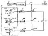
Translated fromKorean제 1 도는 본 발명에 의해서 집적회로를 평가하기 위한 추가회로 요소와 동회로를 검사하기 위한 수단을 포함하는 반도체 집적회로의 일실시예의 회로도.1 is a circuit diagram of one embodiment of a semiconductor integrated circuit comprising additional circuit elements for evaluating integrated circuits and means for inspecting the same circuits according to the present invention.
제 2 도는 본 발명에 의하여 집적회로를 평가하기 위한 다른 추가회로 요소와 동회로를 검사하기 위한 수단을 포함하는 반도체 집적회로의 다른 실시예의 회로도.2 is a circuit diagram of another embodiment of a semiconductor integrated circuit comprising other additional circuit elements for evaluating an integrated circuit and means for inspecting the same circuit according to the present invention.
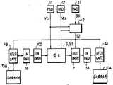
제 3 도는 본 발명에 의하여 제1도와 제2도에 표시된 구성요소들과 결합된 반도체 집적회로의 또 다른 실시예의 블록다이어그램.3 is a block diagram of another embodiment of a semiconductor integrated circuit coupled with the components shown in FIGS. 1 and 2 by the present invention.
제 4 도는 본 발명에 의한 반도체 집적회로의 또 다른 실시예의 회로도.4 is a circuit diagram of another embodiment of a semiconductor integrated circuit according to the present invention.
본 발명은 반도체 집적회로(IC)에 관한 것으로 특히 집적회로들의 특성들을 평가하기 위한 회로소자들을 포함하며 또한 그 평가회로 소자들을 검사하기 위한 수단을 갖는 반도체 집적회로에 관한 것이다.BACKGROUND OF THE INVENTION 1. Field of the Invention The present invention relates to semiconductor integrated circuits (ICs), and more particularly to semiconductor integrated circuits comprising circuit elements for evaluating characteristics of integrated circuits and having means for inspecting the evaluation circuit elements.
반도체 집적회로들은 여러 단계 예를 들면, 반도체 웨이퍼 내에 집적회로를 형성시키는 공정완료 후, 웨이퍼로 부터 집적회로 칩을 잘라 낸 후, 그리고 집적회로 장치를 패케지 처리한 후 등의 여러 단계에서 검사된다.The semiconductor integrated circuits are inspected at various stages, for example, after completion of the process of forming the integrated circuit in the semiconductor wafer, cutting off the integrated circuit chip from the wafer, and packaging the integrated circuit device.
웨이퍼내에 집적회로를 형성시키는 공정 완료후의 검사에서는 웨이퍼 또는 웨이퍼내의 집적회로들의 사용가부를 결정하기 위하여 웨이퍼내의 기본 및 대표적인 회로요소를 예를 들어 저항이나 반도체의 특성을 검사하여 평가한다.In the inspection after completion of the process of forming the integrated circuit in the wafer, the basic and representative circuit elements in the wafer are evaluated, for example, by examining the resistance or the characteristics of the semiconductor, to determine the availability of the wafer or integrated circuits in the wafer.
플립플롭, 앤드게이트와 같은 대표적인 기본 회로들 역시 검사하여 평가한다.Representative basic circuits such as flip-flop and endgate are also examined and evaluated.
각 집적회로 칩내에 형성되어 있는 통상 회로들은 검사 설비(IC 검사기)로 각 집적회로 칩내에 주어진 본딩 패드들을 통하여 검사된다. 그러나 기본회로 요소들은 직접 검사할 수가 없다. 왜냐하면, 그것들은 이미 요구되는 집적회로들을 형성시키기 위하여 웨이퍼 내에서 상호 연결되어 버렸고 따라서 웨이퍼 상에 거의 모든 터미널들이 나타나 있지 않고 표면상에 나타나 있는 다른 터미널들은 너무 작아서 검사기의 탐침을 접촉시킬 수가 없기 때문이다.Conventional circuits formed in each integrated circuit chip are inspected through bonding pads given in each integrated circuit chip with an inspection facility (IC inspector). However, basic circuit elements cannot be directly inspected. Because they have already been interconnected within the wafer to form the required integrated circuits, so almost all terminals are not present on the wafer and other terminals appearing on the surface are too small to touch the probe of the inspector. to be.
그리하여 웨이퍼 또는 웨이퍼 내의 집적회로들의 특성을 검사하고 평가하기 위한 소위 모니터 요소로서 추가의 기본회로 요소들이 웨이퍼의 여분의 자리나, 각 집적회로 칩내에나 또는 특벽한 집적회로 칩으로서 형성된다.Thus, additional basic circuit elements are formed as spare spots in the wafer, within each integrated circuit chip, or as a special integrated circuit chip as so-called monitor elements for inspecting and evaluating the characteristics of the wafer or integrated circuits within the wafer.
이 추가 기본회로 요소들은 통상 회로들을 형성시키는데 사용될 때와 공정에 의해 형성된다. 따라서 통상회로 내의 회로 요소들과 동일한 특성을 갖는 회로 요소들로 간주된다. 그리하여 통상회로를 내의 회로 요소들의 특성들은 추가 회로 요소들을 검사하고 평가함에 의해서 평가된다. 추가회로 요소들을 웨이퍼의 여분의 자리에 형성하는 것이 집적시키는데 유리하긴 하지만 웨이퍼로 부터 집적회로 칩을 잘라낸 후나 패케지 처리한 후에는 각 집적회로 칩의 유효성을 확인할 수 없으며 또한, 특성 검사를 행할 수가 없다. 추가회로 요소들을 각 집적회로 칩내에 형성하면 그것은 집적회로 칩의 수율의 향상에 기여하게 된다. 왜냐하면 사용가부의 결정이나 평가는 각 집적회로 칩마다 행해지기 때문이다.These additional basic circuit elements are typically formed by processes and when used to form circuits. Therefore, they are generally regarded as circuit elements having the same characteristics as the circuit elements in the circuit. Thus, the characteristics of the circuit elements in the conventional circuit are evaluated by examining and evaluating additional circuit elements. Although it is advantageous to integrate additional circuit elements in the extra position of the wafer, it is not possible to verify the validity of each integrated circuit chip after the cutting of the integrated circuit chip from the wafer or after packaging, and also to perform a characteristic test. . Formation of additional circuit elements within each integrated circuit chip contributes to an improvement in the yield of the integrated circuit chip. This is because the determination or evaluation of the usability is made for each integrated circuit chip.
추가회로 요소들을 형성하지 않는 한 단자들에 검사탐침을 접속시키는데 있어서의 문제점은 여전히 남아있게 된다. 추가회로 요소들을 웨이퍼내의 여분의 공간이나 특별한 집적회로 칩으로서 형성할 때 본딩패드들도 역시 추가회로 요소들의 둘레에 통상의 본딩패드를 형성시키는 것과 같은 방법으로 형성된다.The problem of connecting the test probe to the terminals still remains unless additional circuit elements are formed. When forming additional circuit elements as extra space in the wafer or as special integrated circuit chips, the bonding pads are also formed in the same way as forming conventional bonding pads around the additional circuit elements.
그리하여 이들 방법들은 용이하게 상기 문제점을 해결할 것이다. 그러나 전자의 방법은 전기한 바와 같이 각 집적회로 칩의 유효성을 제한하고 또한 집적회로 칩을 절단한 후의 검사를 제한하는 문제점들을 포함하고 있다. 후자의 방법 역시 상기한 문제점들 이외에 웨이퍼 내에서 집적회로 칩들의 활용도가 낮은 문제점을 갖고 있다. 추가회로 요소들을 집적회로 칩내에 형성하였을 때 발생되는 문제점은 크케 증가한다.Thus these methods will easily solve the problem. However, the former method includes the problems of limiting the validity of each integrated circuit chip and limiting inspection after cutting the integrated circuit chip as described above. The latter method also has a low utilization of integrated circuit chips in the wafer in addition to the above problems. The problem that arises when additional circuit elements are formed in an integrated circuit chip is greatly increased.
왜냐하면, 본딩패드의 크기는 상당히 넓은 면적의 사용을 필요로 하기 때문이다. 검사 탐침의 접촉을 가능하게 하기 위하여 예를 들면 약 수십미크론미터×수십미크론미터-100μm×100μm, 그러므로, 명백히 추가본딩 패드들은 집적회로 칩의 집적도 제한으로 인하여 현실적으로 그 각개가 통상 본딩 패드와 같은 크기를 제공 받을 수는 없다. 추가회로 요소들의 검사는 통상 회로들에 사용되지 않는 여분의 통상 본딩 패드들을 사용함으로써 실현시킬 수 있다. 그러나 일반적으로 추가 회로 요소들 전체를 검사할 수 있는 충분한 여분의 통상 본딩 패드들은 없다. 그 각개가 통상 본딩 패드 보다 훨씬 작은 면적을 갖는 특수 본딩 패드들이 각 집적회로 칩내에 제공되었다 할지라도 특수한 형태를 갖는 검사 탐침을 포함하는 특수 검사 장치가 요구된다. 더우기 집적회로의 패케지 처리후의 검사 제한 등이 아직도 남아 있게 된다.This is because the size of the bonding pad requires the use of a fairly large area. In order to enable contact of the inspection probes, for example, several tens of microns x several tens of microns-100 microns x 100 microns, therefore, obviously additional bonding pads are practically each of the same size as the bonding pads due to the integration limitations of the integrated circuit chip. Cannot be provided. Inspection of additional circuit elements can be realized by using extra conventional bonding pads that are not typically used in circuits. In general, however, there are not enough extra conventional bonding pads to inspect all of the additional circuit elements. Although special bonding pads are provided in each integrated circuit chip, each of which typically has a much smaller area than the bonding pad, a special inspection device is required that includes a specially shaped inspection probe. Furthermore, inspection restrictions after package processing of the integrated circuit still remain.
본 발명의 목적은 반도체 집적회로의 특성을 평가하기 위한 회로요소(들)및/또는 회로(를)을 포함하고 상술한 평가회로 요소들이나 평가회로들을 검사하기 위한 작은 크기의 수단을 갖는 반도체 집적회로(IC)를 제공하는 데 있다.SUMMARY OF THE INVENTION An object of the invention is a semiconductor integrated circuit comprising circuit element (s) and / or circuits for evaluating the characteristics of the semiconductor integrated circuit and having a small size means for inspecting the evaluation circuit elements or evaluation circuits described above. To provide (IC).
본 발명의 타의 목적은 상기한 평가회로 요소들 및/또는 평가회로들을 포함하고 쉬운 조작으로 이들을 검사하기 위한 수단을 갖는 반도체 집적회로(IC)를 제공하는 데 있다.Another object of the present invention is to provide a semiconductor integrated circuit (IC) comprising the above evaluation circuit elements and / or evaluation circuits and having a means for inspecting them with easy operation.
본 발명의 또 다른 목적은 상기한 평가회로 요소들 및/또는 평가회로들을 포함하고 반도체 집적회로의 전체 단계 검사에 적용시킬 수 있는 검사수단을 갖는 반도체 집적회로를 제공하는데 있다.It is a further object of the present invention to provide a semiconductor integrated circuit comprising the above evaluation circuit elements and / or evaluation circuits and having an inspection means applicable to all stages inspection of the semiconductor integrated circuit.
본 발명에 의하면 최소한 1개의 회로 ; 최소한 1개의 평가회로 ; 이 회로 및 평가회로 요소들에 동작 가능하게 연결시킬 수 있는 복수의 본딩 패드들 ; 선택적으로 이 회로와 본딩 패드를 간이나 평가회로 요소 그리고 동작 가능하게 이 회로와 연결시킬 수 있는 패드들 간을 선택적으로 연결하는 회로를 포함하는 반도체 집적회로가 제공된다. 이 선택적 연결회로는 본딩 패드들과 평가회로 요소간에 제공된 본딩패드들과 평가회로 요소를 제어 신호에 응하여 스위칭하는 스위칭 회로를 포함하고 있으며, 제어신호에 응하여 평가회로와 연결된 본딩 패드들에 대하여 고임피던스를 주는 회로들을 포함한다.According to the present invention, at least one circuit; At least one evaluation circuit; A plurality of bonding pads operatively connectable to this circuit and evaluation circuit elements; A semiconductor integrated circuit is provided that selectively includes a circuit between the circuit and the bonding pads or between evaluation circuit elements and pads that can be operatively connected to the circuit. The selective connection circuit includes bonding pads provided between the bonding pads and the evaluation circuit element and a switching circuit for switching the evaluation circuit element in response to a control signal, and high impedance with respect to the bonding pads connected to the evaluation circuit in response to the control signal. It includes circuits that give.
선택적 연결회로는 또 시험요청 신호의 수신에 응답하여 제어신호를 출력시키는 회로를 포함한다.The optional connection circuit also includes a circuit for outputting a control signal in response to receiving the test request signal.
제 1 도에서 반도체 웨이퍼내의 금속산화 반도체(MOS)형 집적회로(IC)칩은 통상회로 6,8,9,N-채널MOS(N-MOS) 출력드라이버 71 및 72 그리고 본딩 패드를 31,32,33을 포함하고 있다. 이들 회로 구성 요소들은 통상 목적으로 사용된다. 통상회로 6의 일부분이 제 1 도에 예시되어 있고 한개의 저항 기능을 하는 공핍형 트랜지스터(이후 D트랜지스터라 부름)Q6그리고 한개의 고양형 트랜지스터(이후 E트랜지스터라 부름)Q5로 구성된 제1MOS인버터 61과 한개의 D트랜지스터 Q8과 한개의 E트랜지스터 Q7으로 된 제2MOS인버터 62와 한개의 D트랜지스터 Q10과 한개의 E트랜지스터 Q9로 된 제3MOS인버터 63을 포함하고있다. 제2인버터 62의 한개의 마디 N62는 는 트랜지스터 Q21의 게이트에 연결되어 있다. 제3인버터 63의한개의 마디 N63은 트랜지스더 Q22의 게이트에 연결되어 있다. 직렬연결 트랜지스터들 Q21및 Q22는 N-MOS 출력드라이버 71를 형성시키고 있다.In FIG. 1, a metal oxide semiconductor (MOS) type integrated circuit (IC) chip in a semiconductor wafer typically uses 6, 8, 9, N-channel MOS (N-MOS)
제 1 도에서 MOS-IC칩은 MOS-IC칩내의 집적회로들의 특성을 평가하기 위하여 한개의 회로 요소로서 저항 10과 저항 10을 검사하기 위한 수단을 또 포함하고 있다.In FIG. 1, the MOS-IC chip also includes a means for inspecting the resistor 10 and the resistor 10 as one circuit element to evaluate the characteristics of the integrated circuits in the MOS-IC chip.
이 검사수단은 제어회로 2, 전송케이트 MOS트랜지스터들 41 및 42, MOS트랜지스터 Q11및 Q12, 그리고 본딩 패드들 31-33을 포함하고 있다. 제어회로 2는 한개의 D트랜지스터 Q2와 한개의 E트랜지스터 Q1으로 구성된 제1MOS인버터와 한개의 D트랜지스터 Q4와 한개의 E트랜지스터 Q3로 구성된 제2MOS인버터 22를 포함하고 있다 본딩 패드 31에 연결된 통상회로 9는 후술과 같이 높은 입력 임피던스를 갖는 MOS입력 드라이버를 갖는다. 통상 회로 9내의 이 입력드라이버는 전압 VCC예를 들면 5v와 전압 VEE예를 들면 OV간의 전압에 응답하여 동작한다. 트랜지스터 Q1은 본딩패드 31에 공통연결된 게이트를 갖고 있으며 입력 드라이버로의 상기 전압에 의해서 동작되어서는 않된다.This inspection means comprises
따라서 트랜지스터 Q1의 임계전압 Vth이 전압 VCC보다 높아야 한다. 전압 VCC가 본딩패드 31에 가해질때 제어회로 2는 동작하지 않고 제어신호 S2는 그로부터 저레벨로 유지된다. 다른 한편 트랜지스터 Q1의 임계전압 Vth보다 높은 전압이 본딩패드 31로 공급되었을 때 트랜지스터 Q1은 턴온이 되고 그리하여 트랜지스터 Q3는 턴오프되고 고레벨의 제어신호 S2를 출력한다.Therefore, the threshold voltage Vth of the transistor Q1 must be higher than the voltage VCC . When the voltage VCC is applied to the
전송케이트 트랜지스터 41 및 42는 그를의 게이트들에 제어회로 2로부터 고레벨의 제어신호 S2를 수신할때 동작 가능하게 저항 10을 본딩패드들 32 및 33에 연결시킨다. 트랜지스터 Q7에 병렬연결되어 있는 트랜지스터 Q11은 게이트에 고레벨의 제어신호 S2의 수신에 응답하여 출력드라이버 71의 트랜지스터 Q21이 강제로 턴오프되는 결과와 더불어 마디 N62의 전위를 저레벨로 만든다. 동양으로 트랜지스터 Q9에 병렬 연결되어 있는 트랜지스터 Q12는 역시 게이트에 고레벨의 제어신호 S2의 수신에 응답하여 마디 N63의 전위를 저레벨로 만들고 출력드라이버 71의 트랜지스터 Q22를 턴오프되게 한다. 결과적으로 출력드라이버 71은 본딩패드 32에 대하여 고임피던스를 갖는다.Transfergate
회로 8도 역시 MOS인버터 61-63과 동일한 인버터 이외에 트랜지스터 Q11 및 Q12와 동일한 출력드라이버를 고임피던스로 만드는 트랜지스터들을 포함하고 있다.
제 1 도에 MOS-IC칩의 동작이 설명될 것이다.The operation of the MOS-IC chip will be described in FIG.
정상동작모드에 있어서, VCC와 VEE간의 전압이 본딩패드 31로 공급된다. 회로 9는 본딩패드 31에 공급된 전압에 응답하여 동작된다. 그러나 제어회로 2는 상기 전압에 영향받지 않으므로 제어신호 S2는 그로부터 저레벨로 유지되고 트랜지스터 Q11, Q12및 전송케이트 트랜지스터 41 및 42를 오프 상태로 유지하게 된다.In normal operation mode, the voltage between VCC and VEE is supplied to
마디를 N62 및 N63으로 부터의 드라이버 작동 신호들 S62 및 S63은 트랜지스터들 Q11및 Q12의 영향을 받지 않는다. 저항 10은 본딩패드들 32 및 33으로 부터 분리되고 그리하여 마디 N32 및 33은 저항 10에 연결되지 않는다. 통상회로 6에 있어서의 신호 S60이 곡레벨이고 일방 드라이버 작동신호 S62가 고레벨이고 타방 드라이버 구동신호 S63이 저레벨일 때 출력드라이버 71부터 본딩패드 32로 고레벨의 전압이 출력된다.Note that driver actuation signals S62 and S63 from N62 and N63 are not affected by transistors Q11 and Q12 . Resistor 10 is separated from
그렇지 않으면 출력드라이버 71부터 본딩패드 32에 저레벨 전압이 출력된다. 회로 8 및 출력드라이버 72도 역시 상술한 바와 같이 동작한다.Otherwise, the low level voltage is output from the
검사모드에 있어서는 전술한 바와 같이 전압 VCC보다 충분히 높은 트랜지스터 Q1의 임계전압 Vth보다 높은 전압을 갖인 검사요청 신호가 본딩패드 31에 공급된다.In the test mode, as described above, a test request signal having a voltage higher than the threshold voltage Vth of the transistor Q1 which is sufficiently higher than the voltage VCC is supplied to the
제어회로 2는 고레벨의 제어신호 S2를 출력하여 트랜지스터들 Q11, Q12및 전송 게이트 트랜지스터들 41 및 42를 턴온시키게 한다. 드라이버 작동신호를 S62 및 S63은 신호 S60의 레벨이 저 또는 고가 아닌 한 강제로 저레벨이 되게 한다. 그리하여 출력드라이버 71은 역시 강제로 높은 임피던스를 갖게 한다. 결과적으로 본딩패드들 32 및 33에 전송게이트 트랜지스터들을 거쳐서 단자들에서 연결된 저항 10은 출력드라이버들 71 및 72에 의하여 영향받지 않는다. 이 상태에서 검사탐침들은 본딩패드들 32와 33에 접촉되고 저항 10의 저항을 측정한다.The
이 측정은 MOS-IC칩내에 형성되며 또한 통상회로 6,8,9를 형성하기 위해 사용되는 저항들의 저항 특성의 평가에 사용된다.This measurement is made in the MOS-IC chip and is also used to evaluate the resistance characteristics of the resistors typically used to form
상기 실시예에 있어서 추가본딩패들이 제공되지 않고 정상 본딩패드들 31-33은 정상 작동모드와 검사모드에 공통으로 사용된다.In the above embodiment, no additional bonding paddles are provided and the normal bonding pads 31-33 are commonly used in the normal operation mode and the inspection mode.
이것은 검사수단으로 추가본딩패드들의 제공으로 인한 저집적도의 문제점을 해결해 준다.This solves the problem of low integration due to the provision of additional bonding pads as inspection means.
출력드라이버 고임피던스 형성 트랜지스터들 Q11및 Q12와 전송게이트 트랜지스터를 41 및 42를 구비함으로써 본딩패드를 32 및 33은 선택적으로 지정적으로 상대모드로 부터 아무런 나쁜 영향을 받지 않고 정상동작모드 및 검사모드로 사용된다. 검사는 본딩패드상의 검사탐침을 종래의 방법으로 처리함으로써 쉽게 실행된다.With the output driver high impedance forming transistors Q11 and Q12 and the
평가회로요소들 중의 하나인 저항 10의 검사는 각 집적회로 칩내에 본딩패드들을 형성한 후나 웨이퍼로부터 집적회로 칩들을 잘라내기 전부터 집적회로 칩들을 패케이지 처리하기 전까지의 검사단계들에서 본딩패드들을 사용하여 수행될 뿐만 아니라, 패케이지 처리한 후에 집적회로 패케이지 외부에 갖추어지고 집적회로 패케이지 내의 본딩패드들에 연결되어 있는 접촉핀을 사용하여 수행된다. 상술한 실시예에서 전송게이트 트랜지스터는 평가회로 요소들의 수에 따라 그리고 본딩패드들의 수에 맞게 제공되며 또한 임피던스를 높게 만드는 트랜지스터들도 마찬가지로 평가회로 요소들의 수와 출력드라이버의 수에 맞게 제공된다. 제 2 도에서는 다른 평가회로 요소와 다른 검사수단을 포함하는 다른 MOS-IC칩이 나타내어져 있다The inspection of resistor 10, one of the evaluation circuit elements, uses the bonding pads in the inspection steps after forming the bonding pads in each integrated circuit chip or before cutting the integrated circuit chips from the wafer until packaging the integrated circuit chips. Not only is it performed, but also by using contact pins that are packaged outside the integrated circuit package and connected to bonding pads within the integrated circuit package after the package is processed. In the above-described embodiment, the transfer gate transistors are provided according to the number of evaluation circuit elements and the number of bonding pads, and the transistors for increasing the impedance are also provided for the number of evaluation circuit elements and the number of output drivers. Figure 2 shows another MOS-IC chip comprising different evaluation circuit elements and different inspection means.
제 2 도에서 평가회로 요소는 MOS트랜지스터 11이다. 검사수단은 제 1 도에서와 마찬가지로 전술한 바와같은 제어회로 2, 전송계이트 트랜지스터 44-46 및 본딩패드 31과 본딩패드들 34-36를 포함하고 있다.In FIG. 2, the evaluation circuit element is a MOS transistor 11. The inspection means includes the
저항 기능을 하는 D트린지스터 Q32와 E트랜지스터 Q31, D트랜지스터 Q34, E트랜지스터 Q33, D트랜지스터 Q36, E트랜지스터 Q35로 구성원 인버터들 104-106은 각각 통상회로들의 입력드라이버 기능을 한다. 이 실시예에서 입력드라이버들 104-106은 본딩패드들 34-36에 대하여 충분한 고임피던스를 갖고 있다. 따라서 제 1 도에서 출력드라이버 고임피던스 형성 트랜지스터들 Q11및 Q12에 상응하는 입력드라이버 고임피던스 형성 트랜지스터들은 제공되지 않는다. 이것은 제 1 도 및 제 2 도의 회로 9내의 본딩패드 31에 연결되어 있는 입력드라이버에 적용된 수 있다.D transistors Q32 and E transistors Q31 , D transistors Q34 , E transistors Q33 , D transistors Q36 , and E transistors Q35 as resistors. The inverters 104-106 each function as the input driver of conventional circuits. do. In this embodiment, the input drivers 104-106 have sufficient high impedance for the bonding pads 34-36. Thus, in FIG. 1, input driver high impedance forming transistors corresponding to output driver high impedance forming transistors Q11 and Q12 are not provided. This can be applied to an input driver connected to the
정상동작모드에 있어서, 상술한 VCC및 VEE간의 전압이 본딩패드를 31 및 34-36에 공급될 때 제어회로 2로부터의 제어신호 S2는 저레벨이고 전송게이트 트랜지스터들 44-46은 오프로 만든다. 따라서 트랜지스터 11을 본딩패드들 34-36으로부터 분리시킨다. 결과로서 입력드라이버들 104-106에 연결되어 있는 회로 9와 기타 통상회로들은 본딩패드를 31 및 34-36를 제외한 트랜지스터 11이나 검사수단으로부터 영향받지않고 동작한다.In the normal operation mode, when the voltage between VCC and VEE described above is supplied to the
검사모드에 있어서, 제1도에 나타낸 제어회로 2내의 트랜지스터 Q1의 임계전압 Vth보다 높은 전압을 갖는 검사요청 신호가 본딩패드 31에 공급될 때 제어회로 2는 고레벨을 갖는 제어신호 S2를 출력하고 그 결과 전송게이트 트랜지스터들 44-46은 온이 된다. 그리하여 트랜지스터 11은 본딩패드들 34-36에 동자 가능하게 연결된다. 이 상태에 있어서 검사탐침들을 본딩패드들 34-36에 접촉하여 트랜지스터 11의 각종 특성을 확보한다.In the test mode, when the test request signal having a voltage higher than the threshold voltage Vth of the transistor Q1 in the
트랜지스터 11은 이 형식의 대표적인 트랜지스터로 간주된다.Transistor 11 is considered a representative transistor of this type.
따라서 집적회로 칩내의 이 형식의 트랜지스터들의 평가는 트랜지스터 11에 관하여 확보된 특성을 거쳐 수행된다.The evaluation of this type of transistors in the integrated circuit chip is therefore carried out via the characteristics secured with respect to transistor 11.
입력드라이브들 104 및 106은 본딩패드를 34-36에 대하여 고임피던스를 갖임으로 이 검사는 입력드라이버 104-106에 의해 나쁜 영향을 받지 않는다. 제 1 도와 제 2 도의 상기 실시예들에 있어서 플립플롭 및 앤드게이트와 같은 다양한 평가 기본 회로들은 물론 용량 및 기타 형식의 트랜지스터 등의 다양한 평가회로 요소들이 각 직접회로 칩내에 형성될 수도 있다.Input drives 104 and 106 have high impedance relative to pads 34-36, so this test is not adversely affected by input drivers 104-106. In the above embodiments of FIGS. 1 and 2, various evaluation circuit elements such as flip-flops and end gates, as well as various evaluation circuit elements such as capacitance and other types of transistors, may be formed in each integrated circuit chip.
이 검사수단은 상술한 평가회로 요소들 및/또는 평가 기본회로들을 검사하는데 활용될 수 있다. 명세서에 있어서 평가회로 요소는 기본회로 또는 동류의 대상에 관한 평가를 포함한다. 또한, 상기 제1도와 제2도의 실시예들에 있어서 제어회로 2는 본딩패드 31에 회로 9와 공통으로 연결되어 있다. 본딩패드 31에 정상전압이 가해지지 않도록 하기 위해서 이 제어회로 2는 정상전압의 높은 전압치보다 더 높은 임계전압 Vth을 갖는 트랜지스터 Q1을 포함하고 있다. 그러나 제어회로 2에 통상회로에 사용되지 않는 여분의 본딩패드를 통하여 검사모드를 요청하는 신호 S31이 공급되었을 때 통상 트랜지스터인 특수한 트랜지스터 Q1을 제어회로 2내에 포함시킬 필요는 없다.This inspection means can be utilized to inspect the evaluation circuit elements and / or evaluation basic circuits described above. In the specification, the evaluation circuit element includes an evaluation of the object of the basic circuit or the like. In addition, in the embodiments of FIGS. 1 and 2, the
제어회로 2의 이 검사요청 신호 S31은 VDD와 VEE사이에서 통상전압 범위이다.This test request signal S31 of the
더우기 제어신호 S2는 제 1 도 ALC 제 2 도에 점선으로 표시한 바와 같이 본딩패드 30을 통하여 직접 공급될 수 있다.In addition, the control signal S2 may be directly supplied through the bonding pad 30 as indicated by a dotted line in FIG.
그리하여 제어회로 2는 생략될 수 있다.Thus, the
또한 제 1 도와 제 2 도의 실시예들은 결합될 수도 있다.Also, the first and second embodiments may be combined.
제 3 도는 제 1 도와 제 2 도의 결합 MOS집적회로의 일반적인 블록다이어그램을 나타내고 있다. 제 3 도에 있어서 MOS집적회로는 제 1 도 및 제 2 도내의 통상회로들 6,8,9로 된 통상회로 부분과 제 1 도내의 출력드라이버들 71,72를 갖는 출력드라이버회로 7 및 제 2 도 내의 입력드라이버들 104-106을 갖는 입력드라이버회로 100 그리고 본딩패드 11 및 12를 포함하고 있다.3 shows a general block diagram of the combined MOS integrated circuit of FIGS. In FIG. 3, the MOS integrated circuit includes an
MOS집적회로 역시 제 1 도 내의 평가저항 10과 제 2 도내의 평가트랜지스터 11을 포함하는 검사회로 요소부분들 10A 및 10B를 포함하고 있다.The MOS integrated circuit also includes test
더우기 MOS집적회로는 제 1 도에 나타낸 제어회로 2와 제 1 도내의 트탠지스터들 41,42와 제 2 도에서 트랜지스터들 44,46을 포함하고 있는 전송게이트 트랜지스터 부분 4A로 구성된 검사수단을 포함하고 있다. 본딩패드 31은 통상회로부분과 검사수단을 위하여 공통으로 사용된다.Furthermore, the MOS integrated circuit includes inspection means composed of the
제 1 및 2 도내의 본딩패드들 32,33과 본딩패드들 34-36을 포함하는 입력본딩패드부분 3B는 역시 통상회로 부분과 검사수단을 위하여 공통으로 사용된다. 본딩패드들 11,12는 통상회로, 제어회로 2 그리고 MOS집적회로 내의 기타 회로들에 전원 VCC및 VEE를 공급하기 위하여 사용된다.Input bonding pad portion 3B comprising
본 실시예에 있어서 평가회로 요소들과 통상회로는 집적회로 칩들내에 본딩패드를을 형성한 후와 집적회로 칩의 패케이지 처리 전 사이에 본딩패드들을 사용하여 검사할 뿐만 아니라, 집적회로 칩들의 패케이지 처리한 후에도 집적회로장치의 핀들을 사용하여 검사될 수 있다.In this embodiment, the evaluation circuit elements and the conventional circuit not only inspect the bonding pads after the bonding pads are formed in the integrated circuit chips and before the package processing of the integrated circuit chips, but also the pads of the integrated circuit chips. Even after the cage is processed, it can be inspected using the pins of the integrated circuit device.
검사모드나 정상동작모드 어느 한쪽의 선택은 본딩패드 31에 예정된 전압을 가하거나 가하지 않음으로써 간단히 수행된다.Either the test mode or the normal operation mode is selected simply by applying a predetermined voltage to or without
평가회로 요소들의 검사는 통상회로 검사방법과 유사한 방법으로 행해지고 또한 평가회로 요소를 역시 이 기술 분야에서 잘 알러진 통상회로들에 대한 자동검사를 위한 것과 동일한 방법으로 자동검사 설비를 사용하여 자동적으로 검사된다.The evaluation of the evaluation circuit elements is carried out in a similar manner to the conventional circuit inspection method and the automatic evaluation of the evaluation circuit elements using the automatic inspection facility in the same way as for the automatic inspection of ordinary circuits also well known in the art. do.
제어회로 2의 검사수단과 전송게이트 회로들 4A, 4B 그리고 그들간의 연결 라인들이 점하는 면적은 비교적 작다는 것이 주목할 점이다. 더하여 상술한 바와 같이 제어회로 2는 생략될 수 있다. 이렇게 됨으로써 검사수단을 설비하므로 인한 저집적도는 최소화된다.It is to be noted that the area occupied by the inspection means of the
상기의 실시예들에서 MOS집적회로 칩은 설명되었다. 일반적으로 MOS집적회로 내의 입력드라이버들은 고임피던스를 갖고 있다. 따라서 입력드라이버 고임피던스 제조회로들은 필요치 않다. 만약, 입력드라이버들이 불충분한 고임피던스를 갖이면 입력드라이버에 까지도 고임피던스 형성회로들이 구비되어야 한다. 제 4 도가 이 경우의 실시예를 나타내고 있다.In the above embodiments, the MOS integrated circuit chip has been described. In general, the input drivers in the MOS integrated circuit have high impedance. Therefore, input driver high impedance manufacturing circuits are not needed. If the input drivers have insufficient high impedance, high impedance forming circuits should be provided even in the input driver. 4 shows an embodiment in this case.
제 4 도에 있어서, 쌍극 집적회로 칩은 직렬 연결된 저항 R11과 트랜지스터 T11로 구성된 에미터포로워 입력드라이버 118과 또 직렬 연결된 저항 R12와 트랜지스터 T12로 구성된 에미티포로워 입력드라이버 119를 포함하고 있다.In FIG. 4, the bipolar integrated circuit chip includes an emitter
쌍극집적회로 칩 역시 저항과 검사수단 등의 검사회로요소 12를 포함한다. 검사수단은 제어회로 2'와 인버터 25와 스위칭회로들 48, 49 및 앤드게이트들 58, 59를 포함하고 있다. 이 제어회로 2'는 상술한 바와 같은 동일 기능을 갖고 있으나 쌍극 기술에 의해서 형성되어 있다. 이 스위칭회로들 48, 49는 전송게이트 대신 쌍극트랜지스터들을 포함한다. 본딩패드를 37-39는 상기 실시예드에서의 패드들과 동양의 것이다.The bipolar integrated circuit chip also includes
정상 동작모드에 있어서 검사요청 전압은 본딩패드 37에 가해지지 않는다. 이 제어회로 2'는 저레벨을 갖는 제어신호 S2'를 출력한다. 이 스위칭회로들 48은 검사회로 요소 12와 본딩패드들 38, 39간의 연결을 차단하여 비동력화시킨다. 이 제어신호 S2'는 인버터 25에 의해서 고레벨로 전환된다. 그리고 결과로 생기는 신호 S25는 앤드게이트를 58,59의 단자들을 동력화시킨다. 만약, 본딩패드를 38, 39에 고레벨의 신호가 공급되면 입력드라이버를 118 및 119가 동작된다.In normal operation mode the test request voltage is not applied to
검사모드에 있어서, 검사요청 전압은 본딩패드 37에 공급된다. 제어회로 2'는 고레벨을 갖는 제어신호 S2'를 출력한다. 앤드게이트들 58, 59는 저레벨을 갖는 신호 S25를 가함으로써 억제상태로 된다.In the test mode, the test request voltage is supplied to the
스위칭회로들 48, 49는 동작되어 검사회로 요소 12와 본딩패드들 38, 39간을 연결시킨다. 검사회로요소 12의 특성들은 검사전극들을 본딩패드들에 접속되게 놓음으로서 얻어진다.The switching
위에서 논의원 다양한 변형들은 제 4 도의 실시예에 적용될 수 있다.Various variations above can be applied to the embodiment of FIG. 4.
본 발명의 다수의 광범위하게 상이한 실시예들을 본 발명의 정신과 범위를 이탈됨이 없이 구성시킬 수 있다.Many broadly different embodiments of the invention can be made without departing from the spirit and scope of the invention.
본 발명은 첨부 특허 청구에 한정된 것을 제외하고는 본 명세서에서 설명한 특정 실시예들에 한정되지 않음을 알아야 한다.It should be understood that the invention is not limited to the specific embodiments described herein except as defined in the appended claims.
Claims (7)
Translated fromKoreanApplications Claiming Priority (3)
| Application Number | Priority Date | Filing Date | Title |
|---|---|---|---|
| JP107827 | 1985-05-20 | ||
| JP60-107827 | 1985-05-20 | ||
| JP60107827AJPS61265829A (en) | 1985-05-20 | 1985-05-20 | semiconductor integrated circuit |
Publications (2)
| Publication Number | Publication Date |
|---|---|
| KR860009431A KR860009431A (en) | 1986-12-22 |
| KR900006484B1true KR900006484B1 (en) | 1990-09-01 |
Family
ID=14469041
Family Applications (1)
| Application Number | Title | Priority Date | Filing Date |
|---|---|---|---|
| KR1019860003928AExpiredKR900006484B1 (en) | 1985-05-20 | 1986-05-20 | Semiconductor intergroted circuit |
Country Status (5)
| Country | Link |
|---|---|
| US (1) | US4743841A (en) |
| EP (1) | EP0202905B1 (en) |
| JP (1) | JPS61265829A (en) |
| KR (1) | KR900006484B1 (en) |
| DE (1) | DE3686091T2 (en) |
Families Citing this family (81)
| Publication number | Priority date | Publication date | Assignee | Title |
|---|---|---|---|---|
| US4970454A (en)* | 1986-12-09 | 1990-11-13 | Texas Instruments Incorporated | Packaged semiconductor device with test circuits for determining fabrication parameters |
| JP2579327B2 (en)* | 1987-12-04 | 1997-02-05 | 富士通株式会社 | Semiconductor integrated circuit |
| JPH01238134A (en)* | 1988-03-18 | 1989-09-22 | Fujitsu Ltd | Evaluating method of electro-migration |
| US4947106A (en)* | 1988-03-31 | 1990-08-07 | Hewlett-Packard Company | Programmatically generated in-circuit test of analog to digital converters |
| US4888548A (en)* | 1988-03-31 | 1989-12-19 | Hewlett-Packard Company | Programmatically generated in-circuit test of digital to analog converters |
| US5153509A (en)* | 1988-05-17 | 1992-10-06 | Zilog, Inc. | System for testing internal nodes in receive and transmit FIFO's |
| JPH0258862A (en)* | 1988-08-24 | 1990-02-28 | Nec Corp | Semiconductor integrated circuit |
| US6304987B1 (en) | 1995-06-07 | 2001-10-16 | Texas Instruments Incorporated | Integrated test circuit |
| JP2827229B2 (en)* | 1988-10-14 | 1998-11-25 | 日本電気株式会社 | Semiconductor integrated circuit |
| KR910006241B1 (en)* | 1988-12-14 | 1991-08-17 | 삼성전자 주식회사 | Mode select circuit test |
| JP3005250B2 (en)* | 1989-06-30 | 2000-01-31 | テキサス インスツルメンツ インコーポレイテツド | Bus monitor integrated circuit |
| JPH0389182A (en)* | 1989-08-31 | 1991-04-15 | Sharp Corp | integrated circuit device |
| US5034687A (en)* | 1989-10-16 | 1991-07-23 | Vlsi Technology, Inc. | Signature indicating circuit |
| US5196787A (en)* | 1989-10-19 | 1993-03-23 | Texas Instruments Incorporated | Test circuit for screening parts |
| US5068599A (en)* | 1989-10-23 | 1991-11-26 | Texas Instruments Incorporated | Integrated circuit having an enabling circuit for controlling primary and secondary subcircuits |
| NL8902964A (en)* | 1989-12-01 | 1991-07-01 | Philips Nv | SUBSTRATE INTEGRATED TEST SYSTEM. |
| US5107208A (en)* | 1989-12-19 | 1992-04-21 | North American Philips Corporation | System for partitioning and testing submodule circuits of an integrated circuit |
| JP2556916B2 (en)* | 1990-01-12 | 1996-11-27 | 三菱電機株式会社 | Fault diagnosis device |
| JPH03227547A (en)* | 1990-02-01 | 1991-10-08 | Mitsubishi Electric Corp | Semiconductor device |
| US5030904A (en)* | 1990-02-13 | 1991-07-09 | Hewlett-Packard Company | Diagnostic system for integrated circuits using existing pads |
| KR920007535B1 (en)* | 1990-05-23 | 1992-09-05 | 삼성전자 주식회사 | Semiconductor integrated circuit chip with identification circuit |
| US5070296A (en)* | 1990-06-22 | 1991-12-03 | Honeywell Inc. | Integrated circuit interconnections testing |
| US5130645A (en)* | 1990-08-13 | 1992-07-14 | Vlsi Technology, Inc. | Integrated circuit built-in self-test structure |
| JPH0743399B2 (en)* | 1990-08-15 | 1995-05-15 | 富士通株式会社 | Semiconductor circuit |
| JP2925287B2 (en)* | 1990-10-17 | 1999-07-28 | 富士通株式会社 | Semiconductor device |
| JP2653550B2 (en)* | 1990-11-14 | 1997-09-17 | 三菱電機株式会社 | Solid-state imaging device |
| US5254940A (en)* | 1990-12-13 | 1993-10-19 | Lsi Logic Corporation | Testable embedded microprocessor and method of testing same |
| JP3381929B2 (en)* | 1990-12-27 | 2003-03-04 | 株式会社東芝 | Semiconductor device |
| US5146159A (en)* | 1991-02-01 | 1992-09-08 | Schlumberger Technologies, Inc. | Pin driver for in-circuit test apparatus |
| US5212454A (en)* | 1991-02-04 | 1993-05-18 | Intergraph Corporation, Inc. | Method and apparatus for selecting and measuring a capacitance from a plurality of interconnected capacitances |
| US5371457A (en)* | 1991-02-12 | 1994-12-06 | Lipp; Robert J. | Method and apparatus to test for current in an integrated circuit |
| US5432440A (en)* | 1991-11-25 | 1995-07-11 | At&T Global Information Solutions Company | Detection of tri-state logic signals |
| US5406197A (en)* | 1992-07-31 | 1995-04-11 | International Business Machines Corporation | Apparatus for controlling test inputs of circuits on an electronic module |
| US5383194A (en)* | 1992-11-06 | 1995-01-17 | University Of Texas System Board Of Regents | Integrated logic circuit including impedance fault detection |
| DE4334856A1 (en)* | 1993-10-13 | 1995-05-18 | Bosch Gmbh Robert | Arrangement for testing a gate oxide |
| JP2746172B2 (en)* | 1995-02-02 | 1998-04-28 | 日本電気株式会社 | Semiconductor integrated circuit device |
| EP0745859B1 (en)* | 1995-05-31 | 2004-10-27 | STMicroelectronics, Inc. | Configurable probe pads to facilitate parallel testing of integrated circuit devices |
| US5627478A (en) | 1995-07-06 | 1997-05-06 | Micron Technology, Inc. | Apparatus for disabling and re-enabling access to IC test functions |
| US5994912A (en)* | 1995-10-31 | 1999-11-30 | Texas Instruments Incorporated | Fault tolerant selection of die on wafer |
| US5969538A (en) | 1996-10-31 | 1999-10-19 | Texas Instruments Incorporated | Semiconductor wafer with interconnect between dies for testing and a process of testing |
| US5751158A (en)* | 1995-11-07 | 1998-05-12 | Micron Technology, Inc. | Method and apparatus for selectively deriving a boosted voltage exceeding an internal voltage |
| US6005406A (en)* | 1995-12-07 | 1999-12-21 | International Business Machines Corporation | Test device and method facilitating aggressive circuit design |
| US5796266A (en) | 1996-03-18 | 1998-08-18 | Micron Technology, Inc. | Circuit and a method for configuring pad connections in an integrated device |
| EP0801401B1 (en)* | 1996-04-02 | 2003-08-27 | STMicroelectronics, Inc. | Testing and repair of embedded memory |
| US5654895A (en)* | 1996-04-04 | 1997-08-05 | Lsi Logic Corporation | Process monitor usig impedance controlled I/O controller |
| US5751161A (en)* | 1996-04-04 | 1998-05-12 | Lsi Logic Corporation | Update scheme for impedance controlled I/O buffers |
| US6087842A (en)* | 1996-04-29 | 2000-07-11 | Agilent Technologies | Integrated or intrapackage capability for testing electrical continuity between an integrated circuit and other circuitry |
| US6031403A (en)* | 1996-11-13 | 2000-02-29 | International Business Machines Corporation | Pull-up and pull-down circuits |
| WO1999015909A1 (en)* | 1997-09-22 | 1999-04-01 | Duet Technologies, Inc. | Method for building a testing infrastructure for a system on a semiconductor chip |
| US6408413B1 (en) | 1998-02-18 | 2002-06-18 | Texas Instruments Incorporated | Hierarchical access of test access ports in embedded core integrated circuits |
| US6405335B1 (en) | 1998-02-25 | 2002-06-11 | Texas Instruments Incorporated | Position independent testing of circuits |
| US6313658B1 (en)* | 1998-05-22 | 2001-11-06 | Micron Technology, Inc. | Device and method for isolating a short-circuited integrated circuit (IC) from other IC's on a semiconductor wafer |
| JP2000012639A (en)* | 1998-06-24 | 2000-01-14 | Toshiba Corp | Monitor TEG test circuit |
| KR100311117B1 (en)* | 1998-06-29 | 2001-12-17 | 박종섭 | Optional Function Test Device for Semiconductor Memory Devices |
| US6163867A (en)* | 1998-08-28 | 2000-12-19 | Hewlett-Packard Company | Input-output pad testing using bi-directional pads |
| JP2000214225A (en)* | 1999-01-25 | 2000-08-04 | Rohm Co Ltd | Semiconductor device |
| US6400171B2 (en)* | 1999-03-22 | 2002-06-04 | International Business Machines Corp. | Method and system for processing integrated circuits |
| US6407569B1 (en) | 1999-03-24 | 2002-06-18 | International Business Machines Corporation | Integrated circuit with in situ circuit arrangement for testing integrity of differential receiver inputs |
| US7058862B2 (en) | 2000-05-26 | 2006-06-06 | Texas Instruments Incorporated | Selecting different 1149.1 TAP domains from update-IR state |
| JP3277914B2 (en)* | 1999-04-30 | 2002-04-22 | 日本電気株式会社 | Integrated circuit device having a process parameter measuring circuit |
| US6728915B2 (en) | 2000-01-10 | 2004-04-27 | Texas Instruments Incorporated | IC with shared scan cells selectively connected in scan path |
| US6769080B2 (en) | 2000-03-09 | 2004-07-27 | Texas Instruments Incorporated | Scan circuit low power adapter with counter |
| US6498507B1 (en)* | 2000-04-20 | 2002-12-24 | Analog Devices, Inc. | Circuit for testing an integrated circuit |
| DE10029835C1 (en)* | 2000-06-16 | 2001-10-25 | Infineon Technologies Ag | Integrated circuit with test facility has test switch closed by applied test signal to allow test voltage to be applied to irreversible programmable switches |
| JP2002170886A (en)* | 2000-09-19 | 2002-06-14 | Seiko Instruments Inc | Semiconductor device for reference voltage and method of manufacturing the same |
| US6812726B1 (en)* | 2002-11-27 | 2004-11-02 | Inapac Technology, Inc. | Entering test mode and accessing of a packaged semiconductor device |
| US7240254B2 (en)* | 2000-09-21 | 2007-07-03 | Inapac Technology, Inc | Multiple power levels for a chip within a multi-chip semiconductor package |
| US7444575B2 (en)* | 2000-09-21 | 2008-10-28 | Inapac Technology, Inc. | Architecture and method for testing of an integrated circuit device |
| US8001439B2 (en)* | 2001-09-28 | 2011-08-16 | Rambus Inc. | Integrated circuit testing module including signal shaping interface |
| US7313740B2 (en)* | 2002-07-25 | 2007-12-25 | Inapac Technology, Inc. | Internally generating patterns for testing in an integrated circuit device |
| US8286046B2 (en) | 2001-09-28 | 2012-10-09 | Rambus Inc. | Integrated circuit testing module including signal shaping interface |
| US8166361B2 (en)* | 2001-09-28 | 2012-04-24 | Rambus Inc. | Integrated circuit testing module configured for set-up and hold time testing |
| JP3943890B2 (en)* | 2001-10-18 | 2007-07-11 | 富士通株式会社 | Semiconductor device |
| US7061263B1 (en)* | 2001-11-15 | 2006-06-13 | Inapac Technology, Inc. | Layout and use of bond pads and probe pads for testing of integrated circuits devices |
| US8063650B2 (en) | 2002-11-27 | 2011-11-22 | Rambus Inc. | Testing fuse configurations in semiconductor devices |
| US7138814B2 (en)* | 2003-11-21 | 2006-11-21 | Agere Systems Inc. | Integrated circuit with controllable test access to internal analog signal pads of an area array |
| EP1830195A1 (en)* | 2006-03-02 | 2007-09-05 | Dialog Semiconductor GmbH | Probeless DC testing of CMOS I/O circuits |
| JP5152958B2 (en)* | 2007-04-09 | 2013-02-27 | 株式会社コスモデザイン | Semiconductor integrated circuit device |
| US7772867B2 (en)* | 2008-02-26 | 2010-08-10 | Texas Instruments Incorporated | Structures for testing and locating defects in integrated circuits |
| CN103915416B (en)* | 2013-01-08 | 2016-12-28 | 联咏科技股份有限公司 | Electronic device with thin film chip-on-chip packaging |
| US9846192B2 (en)* | 2015-02-25 | 2017-12-19 | Nxp B.V. | Switched probe contact |
Family Cites Families (7)
| Publication number | Priority date | Publication date | Assignee | Title |
|---|---|---|---|---|
| DE2905271A1 (en)* | 1979-02-12 | 1980-08-21 | Philips Patentverwaltung | INTEGRATED CIRCUIT ARRANGEMENT IN MOS TECHNOLOGY WITH FIELD EFFECT TRANSISTORS |
| DE2905294A1 (en)* | 1979-02-12 | 1980-08-21 | Philips Patentverwaltung | INTEGRATED CIRCUIT ARRANGEMENT IN MOS TECHNOLOGY WITH FIELD EFFECT TRANSISTORS |
| US4243937A (en)* | 1979-04-06 | 1981-01-06 | General Instrument Corporation | Microelectronic device and method for testing same |
| DE2944149C2 (en)* | 1979-11-02 | 1985-02-21 | Philips Patentverwaltung Gmbh, 2000 Hamburg | Integrated circuit arrangement in MOS technology |
| JPS5816542A (en)* | 1981-07-23 | 1983-01-31 | Toshiba Corp | Semiconductor integrated circuit |
| DE3232215A1 (en)* | 1982-08-30 | 1984-03-01 | Siemens AG, 1000 Berlin und 8000 München | MONOLITHICALLY INTEGRATED DIGITAL SEMICONDUCTOR CIRCUIT |
| WO1984002580A1 (en)* | 1982-12-27 | 1984-07-05 | Storage Technology Partners | Vlsi chip with integral testing circuit |
- 1985
- 1985-05-20JPJP60107827Apatent/JPS61265829A/enactiveGranted
- 1986
- 1986-05-16USUS06/863,900patent/US4743841A/ennot_activeExpired - Lifetime
- 1986-05-19EPEP86303791Apatent/EP0202905B1/ennot_activeExpired - Lifetime
- 1986-05-19DEDE8686303791Tpatent/DE3686091T2/ennot_activeExpired - Fee Related
- 1986-05-20KRKR1019860003928Apatent/KR900006484B1/ennot_activeExpired
Also Published As
| Publication number | Publication date |
|---|---|
| EP0202905B1 (en) | 1992-07-22 |
| EP0202905A3 (en) | 1988-01-13 |
| KR860009431A (en) | 1986-12-22 |
| EP0202905A2 (en) | 1986-11-26 |
| DE3686091D1 (en) | 1992-08-27 |
| DE3686091T2 (en) | 1993-03-18 |
| JPS61265829A (en) | 1986-11-25 |
| JPH0351307B2 (en) | 1991-08-06 |
| US4743841A (en) | 1988-05-10 |
Similar Documents
| Publication | Publication Date | Title |
|---|---|---|
| KR900006484B1 (en) | Semiconductor intergroted circuit | |
| US5115191A (en) | Testing integrated circuit capable of easily performing parametric test on high pin count semiconductor device | |
| US4875003A (en) | Non-contact I/O signal pad scan testing of VLSI circuits | |
| KR900005148B1 (en) | Chip on chip semiconductor device | |
| US6121785A (en) | Circuit and a method for configuring pad connections in an integrated device | |
| US6489799B1 (en) | Integrated circuit device having process parameter measuring circuit | |
| US7701789B2 (en) | Semiconductor device | |
| US7466159B2 (en) | Semiconductor integrated circuit having multiple semiconductor chips with signal terminals | |
| US5225774A (en) | Semiconductor integrated circuit | |
| KR910006241B1 (en) | Mode select circuit test | |
| US5870408A (en) | Method and apparatus for on die testing | |
| US5396500A (en) | Semiconductor integrated circuit device with fault detecting function | |
| US6433628B1 (en) | Wafer testable integrated circuit | |
| US5412337A (en) | Semiconductor device providing reliable conduction test of all terminals | |
| JPH0949866A (en) | Integrated circuit | |
| JPH07159493A (en) | Semiconductor device inspection method | |
| JPH0568103B2 (en) | ||
| JP2968642B2 (en) | Integrated circuit device | |
| JP3207639B2 (en) | Semiconductor integrated circuit | |
| JP3132635B2 (en) | Test method for semiconductor integrated circuit | |
| JPH0582652A (en) | Semiconductor integrated circuit device | |
| JPS63257242A (en) | Semiconductor storage device with logic circuit | |
| JP3151315B2 (en) | Semiconductor integrated circuit device | |
| JPH02140947A (en) | Semiconductor device | |
| JP2000114337A (en) | Semiconductor integrated circuit and its characteristics check method |
Legal Events
| Date | Code | Title | Description |
|---|---|---|---|
| A201 | Request for examination | ||
| PA0109 | Patent application | St.27 status event code:A-0-1-A10-A12-nap-PA0109 | |
| PA0201 | Request for examination | St.27 status event code:A-1-2-D10-D11-exm-PA0201 | |
| R17-X000 | Change to representative recorded | St.27 status event code:A-3-3-R10-R17-oth-X000 | |
| PG1501 | Laying open of application | St.27 status event code:A-1-1-Q10-Q12-nap-PG1501 | |
| E902 | Notification of reason for refusal | ||
| PE0902 | Notice of grounds for rejection | St.27 status event code:A-1-2-D10-D21-exm-PE0902 | |
| P11-X000 | Amendment of application requested | St.27 status event code:A-2-2-P10-P11-nap-X000 | |
| P13-X000 | Application amended | St.27 status event code:A-2-2-P10-P13-nap-X000 | |
| G160 | Decision to publish patent application | ||
| PG1605 | Publication of application before grant of patent | St.27 status event code:A-2-2-Q10-Q13-nap-PG1605 | |
| E701 | Decision to grant or registration of patent right | ||
| PE0701 | Decision of registration | St.27 status event code:A-1-2-D10-D22-exm-PE0701 | |
| GRNT | Written decision to grant | ||
| PR0701 | Registration of establishment | St.27 status event code:A-2-4-F10-F11-exm-PR0701 | |
| PR1002 | Payment of registration fee | St.27 status event code:A-2-2-U10-U11-oth-PR1002 Fee payment year number:1 | |
| PR1001 | Payment of annual fee | St.27 status event code:A-4-4-U10-U11-oth-PR1001 Fee payment year number:4 | |
| PR1001 | Payment of annual fee | St.27 status event code:A-4-4-U10-U11-oth-PR1001 Fee payment year number:5 | |
| PR1001 | Payment of annual fee | St.27 status event code:A-4-4-U10-U11-oth-PR1001 Fee payment year number:6 | |
| PR1001 | Payment of annual fee | St.27 status event code:A-4-4-U10-U11-oth-PR1001 Fee payment year number:7 | |
| PR1001 | Payment of annual fee | St.27 status event code:A-4-4-U10-U11-oth-PR1001 Fee payment year number:8 | |
| PR1001 | Payment of annual fee | St.27 status event code:A-4-4-U10-U11-oth-PR1001 Fee payment year number:9 | |
| PN2301 | Change of applicant | St.27 status event code:A-5-5-R10-R13-asn-PN2301 St.27 status event code:A-5-5-R10-R11-asn-PN2301 | |
| PN2301 | Change of applicant | St.27 status event code:A-5-5-R10-R13-asn-PN2301 St.27 status event code:A-5-5-R10-R11-asn-PN2301 | |
| R18-X000 | Changes to party contact information recorded | St.27 status event code:A-5-5-R10-R18-oth-X000 | |
| R18-X000 | Changes to party contact information recorded | St.27 status event code:A-5-5-R10-R18-oth-X000 | |
| PR1001 | Payment of annual fee | St.27 status event code:A-4-4-U10-U11-oth-PR1001 Fee payment year number:10 | |
| PR1001 | Payment of annual fee | St.27 status event code:A-4-4-U10-U11-oth-PR1001 Fee payment year number:11 | |
| PN2301 | Change of applicant | St.27 status event code:A-5-5-R10-R13-asn-PN2301 St.27 status event code:A-5-5-R10-R11-asn-PN2301 | |
| PR1001 | Payment of annual fee | St.27 status event code:A-4-4-U10-U11-oth-PR1001 Fee payment year number:12 | |
| FPAY | Annual fee payment | Payment date:20020822 Year of fee payment:13 | |
| PR1001 | Payment of annual fee | St.27 status event code:A-4-4-U10-U11-oth-PR1001 Fee payment year number:13 | |
| LAPS | Lapse due to unpaid annual fee | ||
| PC1903 | Unpaid annual fee | St.27 status event code:A-4-4-U10-U13-oth-PC1903 Not in force date:20030902 Payment event data comment text:Termination Category : DEFAULT_OF_REGISTRATION_FEE | |
| PC1903 | Unpaid annual fee | St.27 status event code:N-4-6-H10-H13-oth-PC1903 Ip right cessation event data comment text:Termination Category : DEFAULT_OF_REGISTRATION_FEE Not in force date:20030902 | |
| P22-X000 | Classification modified | St.27 status event code:A-4-4-P10-P22-nap-X000 |