KR900006069B1 - Coating device - Google Patents
Coating deviceDownload PDFInfo
- Publication number
- KR900006069B1 KR900006069B1KR1019870013567AKR870013567AKR900006069B1KR 900006069 B1KR900006069 B1KR 900006069B1KR 1019870013567 AKR1019870013567 AKR 1019870013567AKR 870013567 AKR870013567 AKR 870013567AKR 900006069 B1KR900006069 B1KR 900006069B1
- Authority
- KR
- South Korea
- Prior art keywords
- applicator
- arm
- extruder
- dosing pump
- actuating element
- Prior art date
- Legal status (The legal status is an assumption and is not a legal conclusion. Google has not performed a legal analysis and makes no representation as to the accuracy of the status listed.)
- Expired
Links
Images

Classifications
- A—HUMAN NECESSITIES
- A45—HAND OR TRAVELLING ARTICLES
- A45D—HAIRDRESSING OR SHAVING EQUIPMENT; EQUIPMENT FOR COSMETICS OR COSMETIC TREATMENTS, e.g. FOR MANICURING OR PEDICURING
- A45D40/00—Casings or accessories specially adapted for storing or handling solid or pasty toiletry or cosmetic substances, e.g. shaving soaps or lipsticks
- A45D40/26—Appliances specially adapted for applying pasty paint, e.g. using roller, using a ball
- A—HUMAN NECESSITIES
- A45—HAND OR TRAVELLING ARTICLES
- A45D—HAIRDRESSING OR SHAVING EQUIPMENT; EQUIPMENT FOR COSMETICS OR COSMETIC TREATMENTS, e.g. FOR MANICURING OR PEDICURING
- A45D34/00—Containers or accessories specially adapted for handling liquid toiletry or cosmetic substances, e.g. perfumes
- A45D34/04—Appliances specially adapted for applying liquid, e.g. using roller or ball
- A45D34/042—Appliances specially adapted for applying liquid, e.g. using roller or ball using a brush or the like
- A—HUMAN NECESSITIES
- A45—HAND OR TRAVELLING ARTICLES
- A45D—HAIRDRESSING OR SHAVING EQUIPMENT; EQUIPMENT FOR COSMETICS OR COSMETIC TREATMENTS, e.g. FOR MANICURING OR PEDICURING
- A45D34/00—Containers or accessories specially adapted for handling liquid toiletry or cosmetic substances, e.g. perfumes
- A45D34/04—Appliances specially adapted for applying liquid, e.g. using roller or ball
- B—PERFORMING OPERATIONS; TRANSPORTING
- B05—SPRAYING OR ATOMISING IN GENERAL; APPLYING FLUENT MATERIALS TO SURFACES, IN GENERAL
- B05B—SPRAYING APPARATUS; ATOMISING APPARATUS; NOZZLES
- B05B11/00—Single-unit hand-held apparatus in which flow of contents is produced by the muscular force of the operator at the moment of use
- B05B11/0005—Components or details
- B05B11/0035—Pen-like sprayers
- B—PERFORMING OPERATIONS; TRANSPORTING
- B05—SPRAYING OR ATOMISING IN GENERAL; APPLYING FLUENT MATERIALS TO SURFACES, IN GENERAL
- B05B—SPRAYING APPARATUS; ATOMISING APPARATUS; NOZZLES
- B05B11/00—Single-unit hand-held apparatus in which flow of contents is produced by the muscular force of the operator at the moment of use
- B05B11/01—Single-unit hand-held apparatus in which flow of contents is produced by the muscular force of the operator at the moment of use characterised by the means producing the flow
- B05B11/10—Pump arrangements for transferring the contents from the container to a pump chamber by a sucking effect and forcing the contents out through the dispensing nozzle
- B05B11/1001—Piston pumps
- B05B11/1009—Piston pumps actuated by a lever
- B—PERFORMING OPERATIONS; TRANSPORTING
- B05—SPRAYING OR ATOMISING IN GENERAL; APPLYING FLUENT MATERIALS TO SURFACES, IN GENERAL
- B05B—SPRAYING APPARATUS; ATOMISING APPARATUS; NOZZLES
- B05B11/00—Single-unit hand-held apparatus in which flow of contents is produced by the muscular force of the operator at the moment of use
- B05B11/01—Single-unit hand-held apparatus in which flow of contents is produced by the muscular force of the operator at the moment of use characterised by the means producing the flow
- B05B11/10—Pump arrangements for transferring the contents from the container to a pump chamber by a sucking effect and forcing the contents out through the dispensing nozzle
- B05B11/1001—Piston pumps
- B05B11/1023—Piston pumps having an outlet valve opened by deformation or displacement of the piston relative to its actuating stem
- B05B11/1026—Piston pumps having an outlet valve opened by deformation or displacement of the piston relative to its actuating stem the piston being deformable and its deformation allowing opening of the outlet
Landscapes
- Coating Apparatus (AREA)
- Containers And Packaging Bodies Having A Special Means To Remove Contents (AREA)
Abstract
Translated fromKoreanDescription
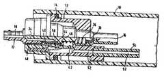
Translated fromKorean제1도는 본 발명에 따른 도포장치의 종단면도.1 is a longitudinal sectional view of the coating apparatus according to the present invention.
제2도는 제1도의 도포장치의 투약펌프장치를 확대한 부분단면도이다.2 is an enlarged partial cross-sectional view of the dosage pump device of the coating device of FIG.
* 도면의 주요부분에 대한 부호의 설명* Explanation of symbols for main parts of the drawings
10 : 컨테이너 11,19 : 배출구10
12 : 투약펌프장치 16 : 유입구12: dosing pump device 16: inlet
17 : 압출기 18 : 관17
20 : 도포요소 21 : 작동요소20: coating element 21: operating element
21a,21b : 아암 22 : 케이스21a, 21b: arm 22: case
23 : 받침점 24 : 신장부23: support point 24: kidney
27 : 결합설비 28 : 날개27: coupling facility 28: wing
29 : 보스 30 : 스터드29: Boss 30: Stud
34 : 피스톤 38 : 비복귀밸브34: piston 38: non-return valve
40 : 슬리이브 46 : 칼라40: sleeve 46: color
48 : 압력평형관 52 : 통기관48: pressure balance pipe 52: vent pipe
본 발명은 (a) 점성물질 특히 손톱니스로 채워진 세장 컨테이너를 갖는 케이스와; (b) 점성물질을 위한 도포요소 특히 연필형 브러시와; (c) 컨테이너로부터 도포요소로 점성물질의 인도를 위한 관을 구비한 도포장치에 관한 것이고, 컨테이너의 배출구와 관의 유입구사이에 있는 제어밸브는 도포요소에 가까이 있으며 도포요소의 축에 가로방향으로 이동가능한 작동요소에 의해서 작동될 수 있다.The present invention provides a kit comprising: (a) a case having an elongated container filled with viscous material, in particular nail varnish; (b) an applicator for a viscous material, in particular a pencil brush; (c) Applicator comprising a tube for the delivery of viscous material from the container to the applicator, wherein a control valve between the outlet of the container and the inlet of the pipe is close to the applicator and transverse to the axis of the applicator. It can be actuated by a movable actuation element.
도포장치는 예를들면 영국특허 명세서 GB-A-531 741에 공지되어 있다. 이 도포장치에서 밸브는 푸시버튼에 의해서 원통공간에 있는 도포요소의 축에 가로로 이동가능한 피스톤이다. 피스톤은 바람직하게 될 때 서로서로 축방향으로 배치된 유입구 및 배출구와 함께 정렬될 수 있는 포오트를 구비한다. 따라서 유입구와 배출구는 동시에 개방되거나 폐쇄된다. 개구들이 개방되어 있는 한 컨테이너의 내용물은 빠져나올 수 있다. 이 도포장치에서 도포요소로 인도되는 양은 한편으로 컨테이너에 있는 각각의 압력에 좌우되고 다른 한편으로 푸시버튼으로 작동되는 제어밸브의 개방시간에 좌우된다.The applicator is known, for example, from British patent specification GB-A-531 741. In this applicator the valve is a piston that is transversely movable on the axis of the applicator element in the cylindrical space by a pushbutton. The piston has a port that can be aligned with the inlets and outlets which are preferably arranged axially with each other when desired. Thus the inlet and outlet are simultaneously opened or closed. As long as the openings are open, the contents of the container can come out. The amount delivered to the applicator in this applicator depends on the one hand on the respective pressure in the container and on the other hand on the opening time of the control valve actuated by the pushbutton.
실제로 푸시버튼의 작동주기가 다양하여 한 작동마다 다른 양들이 도포요소로 인도된다. 그러나 도포요소는 도포요소의 용량을 최대한으로 이용하기 위해 너무 적지않게 또 도포요소로부터 흘러서 떨어지지 않도록 하기 위해 너무 많지 않게 작동마다 같은 양을 항상 수용하게 되어 있다.In practice, the pushbutton's operating cycles are varied so that different quantities are directed to the applicator for each operation. However, the applicator is always adapted to accommodate the same amount per operation, not too little in order to make the best use of the applicator's capacity, and not too much so as not to flow off from the applicator.
독일 특허 명세서 DE-B-13 02 372에는 유입구와 배출구사이의 축방향에서 이동가능한 펌핑요소를 구비한 투약펌프장치(트러스트 피스톤펌프)가 공지되어 있고, 이것은 송출관이 신장되는 축방향 압축기에 의해 작동될 수 있다. 이런 투약펌프장치는 예를들면 안에 담겨진 물질을 뿌리기 위해 약병에 장착된다. 그러나 투약펌프장치의 유입구 및 배출구가 컨테이너의 길이방향에서 서로서로 뒤에 배열되어야 하기 때문에 펌핑요소가 도포장치의 축방향에서 이동가능한 방식으로 이런 투약펌프장치는 상기의 최초에 언급한 종류의 도포장치에만 설치될 수 있다. 그러나 축방향에 있는 투약펌프장치의 작동요소의 조작은 필기구와 같이 손으로 잡아야 하는 손톱니스용 도포장치의 경우에 매우 불편하다. 도포요소의 손상위험 때문에 도포요소의 억압에 의한 투약펌프장치의 작동은 프라이오리(priori)를 방해한다.In German patent specification DE-B-13 02 372 a dosage pump device (thrust piston pump) with a pumping element movable in the axial direction between the inlet and outlet is known, which is provided by an axial compressor in which the outlet pipe is extended. Can work. Such a dosing pump device is, for example, mounted on a vial to spray material contained therein. However, because the inlet and outlet of the dosing pump device must be arranged behind each other in the longitudinal direction of the container, such a dosing pump device is only suitable for the first type of applicator described above in such a way that the pumping elements are movable in the axial direction of the applicator. Can be installed. However, the operation of the operating element of the dosing pump device in the axial direction is very inconvenient in the case of the application device for nail varnish to be held by hand such as writing instruments. Due to the risk of damage to the application element, the operation of the application pump device by the suppression of the application element interferes with the priori.
독일 실용신안 명세서 85 15 618은 페이스트의 도포를 위한 도포장치를 기술하며, 여기서 도포장치는 페이스트를 수용하기 위한 공급탱크를 가진 케이스를 구비하고, 추진 가스용기는 공급탱크로부터 페이스트를 밀어내기 위해 공급탱크뒤에 배열된다. 추진가스용기는 도포요소의 축에 가로로 이동가능한 푸시버튼에 의해서 작동될 수 있는 축방향으로 이동가능한 제어밸브를 구비한다. 이런 푸시버튼은 램프를 거쳐 축방향으로 이동가능한 밸브와 협동한다. 추진가스의 사용이 환경에 유해하다는 사실은 별개문제로 하고 포시버튼을 작동시키기 위한 필요동력은 비교적 크다. 왜냐하면 이동통로가 도포장치로부터 너무 멀리 돌출하지 않도록 하기 위해 비교적 짧아야만하고 램프들사이에 비교적 높은 수준의 마찰이 있기 때문이다. 여기서 짧은 이동통로는 페이스트의 인도가 정도있게 투약될 수 없다는 결론을 갖는다.German Utility Model Specification 85 15 618 describes an applicator for the application of paste, wherein the applicator has a case with a supply tank for accommodating the paste, and the propulsion gas container is supplied to push the paste out of the supply tank. Arranged behind the tank. The propulsion gas container has an axially movable control valve that can be actuated by a pushbutton that is movable transversely to the axis of the applicator element. This pushbutton cooperates with a valve axially movable via a ramp. The fact that the use of propellant gases is harmful to the environment is a separate matter and the driving force for operating the posh button is relatively large. This is because the passage must be relatively short in order not to protrude too far from the applicator and there is a relatively high level of friction between the lamps. The short passage here concludes that the delivery of the paste cannot be adequately administered.
본 발명의 주목적은 간단한 처리로 점성물질의 한정된 양을 정확한 투약으로 인도할 수 있는 것으로 처음에 언급한 종류의 도포장치를 제공하는 것이다.It is a primary object of the present invention to provide an applicator of the kind mentioned initially which can lead to a precise dosage of a limited amount of viscous material with a simple treatment.
따라서 본 발명은 케이스; 손톱니스와 같은 점성물질로 채워진 컨테이너; 이런 점성물질을 위한 도포요소; 이런 점성물질을 컨테이너로부터 도포수단에 인도하기 위한 것; 관의 유입구와 컨테이너의 배출구사이에 있으며 도포요소의 가까이에 있는 작동요소에 의해서 작동가능하고 도포요소의 축에 가로로 이동가능한 제어밸브로 이루어진 도포장치를 제공하는 것이며; 여기서 제어밸브가 투약펌프장치에 통합되고 이 투약펌프장치는 컨테이너의 배출구에 연결된 유입구, 관의 유입구에 연결된 배출구, 도포요소를 점성물질을 인도하기 위해 관이 위치되는 장치내에 축방향 압출기에 의해서 도포장치의 축방향에 있는 유입구와 배출구사이에서 이동가능하게 있는 펌핑요소를 구비하며; 작동요소는 작동요소의 더 긴 아암이 도포장치의 축에 가로로 이동할 때 압출기가 투약펌프장치를 작동하기 위해 더 짧은 아암에 의해서 축방향으로 이동되는 방식으로 도포장치의 케이싱에 힌지되고 L형상의 레버로 설계된다.Thus, the present invention provides a case; Containers filled with viscous materials such as nail varnishes; Application elements for such viscous materials; For guiding such viscous material from the container to the application means; To provide an applicator comprising a control valve between the inlet of the tube and the outlet of the container and operable by an actuating element proximate to the applicator element and movable transverse to the axis of the applicator element; Here the control valve is integrated into the dosing pump device, which is applied by an axial extruder in the device where the pipe is located to guide the viscous material to the inlet connected to the outlet of the container, the outlet connected to the inlet of the pipe, A pumping element movably between an inlet and an outlet in the axial direction of the apparatus; The actuating element is hinged to the casing of the applicator and L-shaped in such a way that the extruder is moved axially by the shorter arm to actuate the dosing pump device when the longer arm of the actuating element moves transversely to the axis of the applicator. It is designed as a lever.
상기 처음에 언급한 종류의 도포장치에 있는 공지의 투약펌프장치의 사용 때문에 도포장치로 한정된 양을 인도할 수 있다. 단 한번의 완전한 도포요소의 억압은 점성물질 예를들면 손톱니스의 소정량을 인도하며, 이 소정량은 손톱하나를 칠하기에 충분히 많은 양이다. 도포장치가 필기구같이 손에 쥐어질 수 있고 도포요소가 엄지손가락에 의해 쉽게 또 정밀하게 조작될 수 있기 때문에 조작은 매우 간단하고 편리하다. 램프에 의해 압출기와 협동하는 푸시버튼과 비교하여 본 발명의 L형상의 레버는 긴 레버통로 때문에 작동력이 작다는 장점을 갖는다. 도포요소의 실질적으로 더 긴 작동통로가 압출기의 작은 이동을 필요로하고 이에 따라 제어밸브가 작은 개구를 필요로 하기 때문에 긴 레버통로는 또한 양호한 투약을 가능하게 한다. 도포요소는 예를들면 단지 중간정도만 억압될 수 있다.Due to the use of the known dosing pump device in the applicator of the kind mentioned above, a limited amount can be delivered to the applicator. The suppression of a single complete application element leads to a predetermined amount of viscous material such as nail varnish, which is large enough to paint a single nail. Operation is very simple and convenient because the applicator can be held in the hand like a writing instrument and the applicator can be easily and precisely operated by the thumb. Compared to the pushbutton cooperating with the extruder by the lamp, the L-shaped lever of the present invention has the advantage of low operating force because of the long lever passage. Longer lever passages also allow good dosing because the substantially longer working passage of the applicator element requires a smaller movement of the extruder and thus the control valve requires a smaller opening. The applicator element can only be moderately suppressed, for example.
L형상 도포요소의 받침점은 짧은 아암의 자유단에 적절히 위치된다. 이것은 받침점이 L형상 레버의 짧은 아암과 긴 아암사이의 접합지점에 위치되는 경우보다 더 긴 레버통로를 필요로 한다.The supporting point of the L-shaped application element is appropriately located at the free end of the short arm. This requires a longer lever path than if the support point is located at the junction between the short and long arms of the L-shaped lever.
바람직하게 L형상의 작동요소의 긴 아암은 도포장치의 케이스를 에워싸는 날개를 측면에 구비한다. 한편으로 이들 날개는 도포요소의 안내를 거들고, 다른 한편으로 이들 날개들은 도포장치의 케이스와 작동요소의 긴 아암 사이의 공간으로 불순물의 침투에 대항하여 보호한다. 또한 날개들은 도포장치에 더 좋은 외관을 제공한다.Preferably the long arm of the L-shaped actuating element has a flank on the side surrounding the case of the applicator. On the one hand these wings help guide the applicator element and on the other hand these wings protect against the penetration of impurities into the space between the case of the applicator and the long arm of the actuating element. The wings also give the applicator a better appearance.
날개의 내측부에서 도포장치의 케이스에 있는 대응하는 리세스와 협동하는 하나 또는 다수의 보스가 제공될 수 있다. 이런 설계는 손톱니스 도포장치의 사용자에게 도포요소가 작동되고 이에 따라 투약을 손쉽게 하는 정도의 감각을 제공한다. 특히 이런 특징은 작동요소의 완전히 억압된 위치에서 사용될 수 있다. 즉 사용자가 투약펌프장치를 이미 완전하게 작동하였는지 또는 작동하지 않았는지를 사용자가 명확히 감지하도록 날개의 내부측에 있는 한 보스는 도포장치의 케이싱에 있는 리세스에 탄력성있게 결합될 수 있다. 리세스에 보스의 결합은 "클릭효과"를 만들도록 소리의 발생을 겸비할 수 있다.One or more bosses may be provided which cooperate with corresponding recesses in the case of the applicator at the inner side of the wing. This design provides the user of the nail varnish applicator with the degree to which the applicator is activated and thus facilitates the dosing. In particular, this feature can be used in the fully suppressed position of the actuating element. That is, the boss can be elastically coupled to the recess in the casing of the applicator so that the user clearly senses whether the user has already fully or not operated the dosing pump device. The coupling of the boss to the recess can combine the generation of sound to create a "click effect".
바람직하게 작동요소의 짧은 아암은 양측에 있는 압출기를 에워싸고 압출기의 반경방향으로 돌출하는 스터드상에서 지탱된다. 이 설계는 힘의 평형을 확실하게 하고, 이에따라 양호한 안정성을 가질 수 있으며 강한 특성으로 두드러진다. 작동요소의 긴 아암이 억압될 때 압출기의 반경방향스터드는 포오크형상의 짧은 아암을 경유하여 힘을 받고, 압출기는 이것과 함께 이동된다.Preferably the short arm of the actuating element is carried on a stud which encloses the extruders on both sides and projects radially of the extruder. This design ensures a balance of forces, and thus can have good stability and stands out for its strong properties. When the long arm of the actuating element is suppressed, the radial stud of the extruder is forced through the fork-shaped short arm and the extruder moves with it.
더욱이 예를들면 환상설계에서 작동요소의 짧은 아암이 바람직하게 압출기를 아래로부터 에워싸고 한쌍의 결합요소와 협동하는 포옹부품에서 결합요소를 구비한다.Furthermore, for example in the annular design, the short arm of the actuating element preferably has the engaging element in the hug part which encloses the extruder from below and cooperates with the pair of engaging elements.
따라서 압출기는 예를들면 작동요소를 경유하는 작동이 예정될 때 도포요소의 뒤로 부주의한 푸싱에 의해 압출기를 경유하는 투약펌프장치를 작동을 방지하기 위해 축방향에서 정지된다.The extruder is thus axially stopped to prevent operation of the dosing pump device via the extruder, for example by inadvertent pushing behind the applicator when operation via the actuating element is scheduled.
힘을 받지 않는 위치에서 작동요소를 정지시키기 위해 커버캡이 도포요소를 보호하도록 도포장치상에 장착되고, 더욱이 긴 아암은 바람직하게 L형상의 작동요소의 긴 아암과 짧은 아암 사이의 접합지점에서 연장부를 가질 수 있고; 이 긴 아암은 점성물질을 도포요소의 우연한 공급과 같은 경우를 방지하기 위해 커버캡의 슬롯에 결합되게 연결된다.A cover cap is mounted on the applicator to protect the applicator element in order to stop the actuating element in a non-forced position, furthermore the long arm preferably extends at the point of contact between the long and short arms of the L-shaped actuating element. May have wealth; This long arm is coupled to the slot of the cover cap to prevent viscous material such as accidental supply of application elements.
본 발명의 다른 목적과 특징은 첨부도면을 참고하여 바람직한 실시예의 다음 설명으로 더 명백할 것이다.Other objects and features of the present invention will become more apparent from the following description of the preferred embodiments with reference to the accompanying drawings.
손톱니스용 도포장치는 관형 컨테이너(10)를 구비하며, 이 컨테이너의 배출구(11)에는 투약펌프장치(12)가 삽입된다. 투약펌프장치의 유입구는 참조번호 16이다. 제1도에서 상세히 도시하지 않은 펌핑요소는 도포장치에 대하여 축방향으로 이동가능하고 압출기(17)에 의해서 작동되며, 이 압출기내에는 투약펌프장치(12)의 배출구(19)와 연통하는 도포요소(20)(이 경우에서 연필형브러시)로 인도되는 관(18)이 신장된다.The application device for nail varnish has a
압출기(17)는 펌핑요소를 작동하기 위해 축방향으로 이동될 수 있다. 압출기는 L형상의 작동요소(21)에 의해서 이동되고 도포장치의 케이스(22)의 한 단부에 힌지되며; 컨테이너(10)는 도시한 바와같이 케이스(22)의 다른 단부에 나사고정된다.The
제1도에 명확히 도시한 바와같이 L형상의 레버의 받침점(23)이 환상으로 있는 짧은 아암(21b)의 자유단부에 위치하여서 압출기(17)가 통하여 지날 수 있다. L형상의 작동요소(21)의 안정위치에서 도포장치의 축방향에 수직으로 신장된 짧은 아암(21b)과는 현저히 달라서 L형상의 작동요소(21)의 긴 아암(21a)은 포도장치의 축에 단지 약간 경사져 신장되고 짧은 아암(21b)과의 접합지점에서 신장부(24)를 구비하고, 이 신장부는 작동요소(21)의 안정위치에서 또 커버캡(25)이 장착될 때 커버캡의 슬롯(26)에 결합되어서 작동요소(21)가 정지된다. 도시한 바와같이 아래로부터 압출기(17)를 에워싸는 짧은 아암(21b)의 그 부품상에서 결합돌출과 협동하는 예를들면 압출기(17)에 있는 결합 리세스의 형태로 아래에서부터 압출기(17)를 에워싸는 짧은 아암(21b)의 부품에서 다른 정지를 제공할 수 있다.As clearly shown in FIG. 1, the
이 결합설비(27)는 작동요소(21)의 안저위치에서 커버캡(25)이 나사풀림될 때 압출기(17)가 더 축방향으로 고정되어 투약펌프장치(12)가 도포요소(20)의 부주의한 억압에 의해서 작동될 수 없게 하는 것을 확실히 한다. 이 멈춤설비는 작동요소(21)가 억압되어 투약펌프장치(12)가 작동될 수 있을 때 자동적으로 해제된다.The
작동요소(21)의 긴아암(21a)을 도포장치의 케이스(22)와 긴 아암(21a)사이의 공간으로 불순물의 침입을 주로 방지하기 위해 도포장치의 케이스(22)를 에워싸는 날개(28)를 양측에서 구비한다 : 또한 날개들은 시각적인 외관을 향상시킨다. 한 날개의 내부측에서 또는 양날개의 내부측에서 하나 또는 다수의 보스(29)는 케이스(22)의 외측에서 상세히 도시하지 않은 리세스와 협동하도록 되어 있고 감촉에 의해서 이미 억압된 작동요소의 범위를 나타내도록 되어 있다. 그러나 적어도 하나의 보스가 작동요소의 전체 작동을 표시할 수 있고 이에 따라 투약펌프장치의 전체 작동도 표시할 수 있다.
또한 이 경우에 한 보스가 들을 수 있는 "클릭효과"를 얻는 방식으로 보스와 리세스를 설계하는 것이 적절하다.Also in this case it is appropriate to design the boss and recess in such a way as to obtain a "click effect" that a boss can hear.
필요시 플라스틱 재료가 충분한 탄력성을 갖기 때문에 플라스틱 재료가 도포장치의 구조에 바람직한 재료이다. 받침점(23)은 예를들면 도포장치의 케이스(22)에 있는 대응하는 리세스에 결합하도록 작동요소(21)의 짧은 아암(21b)에서만 굵게 될 수 있다.Plastic materials are the preferred materials for the construction of the applicator because the plastic materials have sufficient elasticity if necessary. The supporting
제2도에 도시한 투약펌프장치는 압출기(17)에 의해 작동되는 피스톤(34)를 구비하고, 이 피스톤(34)은 압출기(17)에 대항하여 피스톤을 미는 스프링(36)에 의해 압출기(17)로부터 먼 단부에서 지지된다. 유입구(16)의 가까이 있는 투약펌프장치의 이 단부에서 볼밸브형태로 있는 비복귀밸브(38)가 있다. 제2도에 도시한 바와같이 피스톤(34)은 탄성 슬리이브(40)로 에워싸고, 이 슬리이브는 압출기(17)상에 지지되며 압출기(17)에 맞은편의 단부에서 피스톤(34)를 위한 원통공간의 내부벽(42)상에 있다.The dosing pump device shown in FIG. 2 has a
더욱이 제2도에 도시한 안정위치에서 슬리이브는 원통공간의 내부벽(42)에 접하는 단부와 압출기(17)상에 지지되는 단부사이에서 피스톤을 에워싸는 칼라(46)상의 시이팅(44)에 있다. 시이팅(44)은 컨테이너(10)로부터 도포요소(20)로 손톱니스의 인도를 제어하는 제어밸브를 구성한다. 손톱니스는 유입구(16)를 경유하여 비복귀밸브(38)를 지나서 원통공간의 내부벽(42)과 피스톤(34)사이로 흐르고, 슬리이브(40)가 칼라(46)로부터 이격되면 시이팅(44)을 지나고, 슬리이브(40)와 피스톤(34)의 몸체사이에서 벨과 같은 방식으로 피스톤(34)을 에워싸는 압출기(17)로 지나가며 관(18)으로 송출된다.Furthermore, in the stable position shown in FIG. 2 the sleeve is in a seating 44 on the
제2도에서 압출기(17)가 우측을 향하여 밀리면 슬이이브(40)뿐만 아니라 피스톤(34)은 스프링(36)의 힘에 대항하여 우측으로 밀리고, 비복귀밸브(38)와 시이팅(44)사이의 액체는 압축된다. 이 과정에서 비복귀밸브(38)는 자동적으로 폐쇄위치에 있다. 어느정도의 액체압축후 탄성 슬리이브(40)는 칼라(46)로부터 분리되고, 즉 제어밸브가 자동적으로 개방되며 압축유체가 송출관(18)으로 흐를 수 있다. 이에 따라 초기 설정된 유체의 양이 초기 설정된 압력에서 송출되고, 이 초기설정된 양의 송출후 다시 제어밸브는 자동적을 폐쇄되고, 스프링(36)은 초기 위치로 되돌아가도록 슬리이브(40)와 압출기(17)로 피스톤(34)을 편의시킨다.In FIG. 2, when the
컨테이너(10)로부터 액체가 더 덜어짐에 따라 컨테이너(10)의 압력이 감소되어서, 결국에는 특별한 압력 평형조처가 취해지지 않으면 외부압력이 너무 높아서 액체가 더 이상 배출되지 않게된다. 적절한 경우에서 이들 조치는 투약펌프장치(12)의 케이스와 압출기(17)사이에 위치된 압력평형관(48)으로 형성되고 도포요소에 액체의 인도를 제어하는 동일한 제어밸브로 제어된다. 제2도에 도시한 바와같이 안정위치에서 슬리이브(40)는 피스톤(34)의 칼라(44)뿐만 아니라 투약펌프장치의 케이스에 대항하여 맞은편에 기대고 있다. 따라서 안정위치에서 즉 도포장치가 사용되지 않을 때 압력평형관(48)은 폐쇄된다. 제2도에서 피스톤(34)이 비복귀밸브(38)와 시이팅(44)사이의 액체를 압축하기 위해 우측을 향하여 밀릴 때 슬리이브(40)가 칼라(46)로부터 분리되기전에 제어밸브는 바람직하게 압력평형관(48)을 개방하고, 이에 따라 도포요소로 액체의 인도가 자유로이 된다. 따라서 압력평형이 사전에 행해진다. 압력평형관이 개방되거나 폐쇄되는 구역은 참조번호 50으로 가리킨다.As the liquid is removed from the
밸브영역(50)에서 외부로부터 유입되는 공기는 투약펌프장치의 케이싱에서 시작되는 통기관(52)으로 지나고, 제1도에 도시한 바와같이 비복귀밸브(58)로 폐쇄되는 단부를 갖는 튜브렛(54)으로써 계속된다. 이 비복귀밸브(58)는 도포액체가 압력평형관(48)이나 통기구역(50)으로 지나지 않도록 방지하고 가령 태양의 가열에 의해 발생될 수 있는 컨테이너의 과다압력의 경우에 통기관을 막아서 건조되는 것을 방지한다.Air flowing from the outside in the
본 발명에서 사용되는 격리펌프장치는 독일 특허 명세서 DE-B-1 302 372에 공지되어 있다.The isolation pump device used in the present invention is known from German patent specification DE-B-1 302 372.
더욱이 제1도에서 알 수 있는 바와같이 압출기(17)는 맞은편에 반경방향 스터드(30)를 구비하며, 이 스터드는 투약펌프장치(12)의 탄성력에 대향하여 압출기를 이동시키기 위해 압출기(17)를 에워싸는 짧은 아암(21b)의 측면부품과 협동한다.Furthermore, as can be seen in FIG. 1, the
Claims (8)
Translated fromKoreanApplications Claiming Priority (2)
| Application Number | Priority Date | Filing Date | Title |
|---|---|---|---|
| DE3641392ADE3641392C1 (en) | 1986-12-04 | 1986-12-04 | Application device |
| DEP3641392.5 | 1986-12-04 |
Publications (2)
| Publication Number | Publication Date |
|---|---|
| KR880007035A KR880007035A (en) | 1988-08-26 |
| KR900006069B1true KR900006069B1 (en) | 1990-08-22 |
Family
ID=6315433
Family Applications (1)
| Application Number | Title | Priority Date | Filing Date |
|---|---|---|---|
| KR1019870013567AExpiredKR900006069B1 (en) | 1986-12-04 | 1987-11-30 | Coating device |
Country Status (6)
| Country | Link |
|---|---|
| US (1) | US4810124A (en) |
| KR (1) | KR900006069B1 (en) |
| DE (1) | DE3641392C1 (en) |
| FR (1) | FR2607732B1 (en) |
| GB (1) | GB2200041B (en) |
| IT (1) | IT1211572B (en) |
Families Citing this family (10)
| Publication number | Priority date | Publication date | Assignee | Title |
|---|---|---|---|---|
| DE3736095A1 (en)* | 1987-10-24 | 1989-05-03 | Schwan Stabilo Schwanhaeusser | Applicator |
| DE3820184A1 (en)* | 1988-06-14 | 1989-12-21 | Schwan Stabilo Schwanhaeusser | APPLICATION DEVICE FOR A VISCOSE, PREFERABLY COSMETIC MASS |
| DE19617777A1 (en)* | 1996-05-03 | 1997-11-06 | Ahrens Hans Joachim | Correcting pen for correcting fluids, nail polishes etc |
| JPH11206453A (en)* | 1998-01-20 | 1999-08-03 | Ikeda Bussan Kk | Side knock type container |
| US6623201B2 (en)* | 2000-09-08 | 2003-09-23 | John Francois Brumlik | Cleaning device and method of use |
| AU2003900110A0 (en)* | 2003-01-10 | 2003-01-23 | Pariece Pty Ltd | Nail polish applicator |
| KR200338799Y1 (en)* | 2003-09-08 | 2004-01-24 | 변영광 | Make-up apparatus for cosmetics of liquid type |
| US20090311036A1 (en)* | 2008-06-12 | 2009-12-17 | Zen Design Solutions Limited | Dispensing device for consumer products |
| KR200456236Y1 (en)* | 2008-12-16 | 2011-10-20 | 주식회사 하나 | A standard capacity discharge case of liquid content |
| CN106231956B (en)* | 2014-05-08 | 2019-07-09 | 高露洁-棕榄公司 | Oral care implement |
Family Cites Families (15)
| Publication number | Priority date | Publication date | Assignee | Title |
|---|---|---|---|---|
| US1004936A (en)* | 1910-11-22 | 1911-10-03 | Bedros M Terzian | Fountain blacking-brush. |
| GB122784A (en)* | 1918-07-08 | 1919-02-06 | William Ingram | An Improved Brush for Applying Varnishes and like Substances. |
| US1376702A (en)* | 1920-06-24 | 1921-05-03 | Miles M Kellogg | Fountain paint-brush |
| US1700807A (en)* | 1927-01-25 | 1929-02-05 | Dannie E Newton | Dispensing device |
| GB480873A (en)* | 1936-09-18 | 1938-03-28 | Aero Brush Company Ltd | Improvements in or relating to apparatus for supplying paints and other liquids to surfaces |
| GB531741A (en)* | 1939-08-01 | 1941-01-09 | Clairol N V | Improvements in devices for the dyeing and bleaching of human hair |
| US2417370A (en)* | 1944-12-13 | 1947-03-11 | Diagraph Bradley Stencil Machi | Fountain brush |
| US2642607A (en)* | 1950-03-06 | 1953-06-23 | Delbert J Bozzalla | Charge ejecting nail polish applicator |
| US2715236A (en)* | 1953-04-07 | 1955-08-16 | Tereno Jack | Liquid ejector and applicator |
| DE1302372C2 (en)* | 1967-01-17 | 1978-06-08 | Pfeiffer Zerstäuber-Vertriebsgesellschaft mbH & Co KG, 7760 Radolfzell | SINGLE-ACTING MANUAL PISTON PUMP BUILT IN A VESSEL |
| US3603694A (en)* | 1969-11-10 | 1971-09-07 | Ronald D Hamm | Device for feeding paint to a painting brush |
| US3883253A (en)* | 1972-03-03 | 1975-05-13 | Pentel Kk | Mechanical pencil |
| US4132359A (en)* | 1976-04-09 | 1979-01-02 | Yoshino Kogyosho Co., Ltd. | Manually operative atomizer |
| US4640638A (en)* | 1983-03-24 | 1987-02-03 | Sani-Fresh International, Inc. | Cleaning system |
| DE8515618U1 (en)* | 1985-05-28 | 1985-07-11 | Alpina Plast AG, Eichberg, St. Gallen | Device for pressing out and applying pastes |
- 1986
- 1986-12-04DEDE3641392Apatent/DE3641392C1/ennot_activeExpired
- 1987
- 1987-11-23USUS07/123,766patent/US4810124A/ennot_activeExpired - Fee Related
- 1987-11-26GBGB8727653Apatent/GB2200041B/ennot_activeExpired - Lifetime
- 1987-11-30KRKR1019870013567Apatent/KR900006069B1/ennot_activeExpired
- 1987-12-01ITIT8768037Apatent/IT1211572B/enactive
- 1987-12-01FRFR878716638Apatent/FR2607732B1/ennot_activeExpired - Lifetime
Also Published As
| Publication number | Publication date |
|---|---|
| GB2200041B (en) | 1990-03-21 |
| FR2607732A1 (en) | 1988-06-10 |
| IT8768037A0 (en) | 1987-12-01 |
| GB2200041A (en) | 1988-07-27 |
| KR880007035A (en) | 1988-08-26 |
| FR2607732B1 (en) | 1990-04-13 |
| GB8727653D0 (en) | 1987-12-31 |
| IT1211572B (en) | 1989-11-03 |
| US4810124A (en) | 1989-03-07 |
| DE3641392C1 (en) | 1988-05-26 |
Similar Documents
| Publication | Publication Date | Title |
|---|---|---|
| US4921142A (en) | Manually operable fluid dispenser | |
| AU722098B2 (en) | Device for dispensing liquids | |
| US5257726A (en) | Dispenser for flowable media | |
| JP3381917B2 (en) | Media ejection device | |
| US4175704A (en) | Non-aerosol continuous spray dispenser | |
| US4067499A (en) | Non-aerosol continuous spray dispenser | |
| US4274560A (en) | Atomizing pump dispenser | |
| US5417258A (en) | Rechargeable device for spraying a fluid | |
| KR900006069B1 (en) | Coating device | |
| KR101833957B1 (en) | Cosmetic dispenser | |
| US3474938A (en) | Sprayer and dispenser mechanism | |
| HU221949B1 (en) | Trigger pump liquid dispenser | |
| US5405060A (en) | Liquid spray device | |
| EP0484615B1 (en) | Manually operated pump device for dispensing fluids | |
| CZ153199A3 (en) | Pumping dosing apparatus | |
| US5361944A (en) | Device for the conditioning and the distribution of pasty or liquid products | |
| US4674658A (en) | Fluid dispenser | |
| EP3150287A1 (en) | Trigger-type liquid sprayer | |
| BR9609770A (en) | Multi-part liquid applicator | |
| CN101443128A (en) | Fluid product dispensing pump | |
| US5234132A (en) | Actuator for dispensing pump | |
| US7159796B2 (en) | Device for spraying a substance onto a medium | |
| US5437398A (en) | Media dispenser with isolated pump restoring system | |
| CN109649820B (en) | Fluid product dispenser | |
| US3672545A (en) | Air pressure operated dispenser |
Legal Events
| Date | Code | Title | Description |
|---|---|---|---|
| PA0109 | Patent application | St.27 status event code:A-0-1-A10-A12-nap-PA0109 | |
| R17-X000 | Change to representative recorded | St.27 status event code:A-3-3-R10-R17-oth-X000 | |
| A201 | Request for examination | ||
| PA0201 | Request for examination | St.27 status event code:A-1-2-D10-D11-exm-PA0201 | |
| PG1501 | Laying open of application | St.27 status event code:A-1-1-Q10-Q12-nap-PG1501 | |
| G160 | Decision to publish patent application | ||
| PG1605 | Publication of application before grant of patent | St.27 status event code:A-2-2-Q10-Q13-nap-PG1605 | |
| E701 | Decision to grant or registration of patent right | ||
| PE0701 | Decision of registration | St.27 status event code:A-1-2-D10-D22-exm-PE0701 | |
| GRNT | Written decision to grant | ||
| PR0701 | Registration of establishment | St.27 status event code:A-2-4-F10-F11-exm-PR0701 | |
| PR1002 | Payment of registration fee | St.27 status event code:A-2-2-U10-U11-oth-PR1002 Fee payment year number:1 | |
| LAPS | Lapse due to unpaid annual fee | ||
| PC1903 | Unpaid annual fee | St.27 status event code:A-4-4-U10-U13-oth-PC1903 Not in force date:19930823 Payment event data comment text:Termination Category : DEFAULT_OF_REGISTRATION_FEE | |
| PC1903 | Unpaid annual fee | St.27 status event code:N-4-6-H10-H13-oth-PC1903 Ip right cessation event data comment text:Termination Category : DEFAULT_OF_REGISTRATION_FEE Not in force date:19930823 | |
| P22-X000 | Classification modified | St.27 status event code:A-4-4-P10-P22-nap-X000 |