KR900000983B1 - Electronic electricity meter - Google Patents
Electronic electricity meterDownload PDFInfo
- Publication number
- KR900000983B1 KR900000983B1KR1019870003407AKR870003407AKR900000983B1KR 900000983 B1KR900000983 B1KR 900000983B1KR 1019870003407 AKR1019870003407 AKR 1019870003407AKR 870003407 AKR870003407 AKR 870003407AKR 900000983 B1KR900000983 B1KR 900000983B1
- Authority
- KR
- South Korea
- Prior art keywords
- power
- signal
- voltage
- circuit
- current
- Prior art date
- Legal status (The legal status is an assumption and is not a legal conclusion. Google has not performed a legal analysis and makes no representation as to the accuracy of the status listed.)
- Expired
Links
- 230000005611electricityEffects0.000titleclaimsdescription6
- 230000002093peripheral effectEffects0.000claimsdescription7
- 238000001514detection methodMethods0.000claimsdescription4
- 230000010354integrationEffects0.000claimsdescription3
- 238000010586diagramMethods0.000description7
- 238000000034methodMethods0.000description6
- 238000004364calculation methodMethods0.000description4
- 230000006870functionEffects0.000description4
- 238000006243chemical reactionMethods0.000description2
- 238000013500data storageMethods0.000description2
- 230000001939inductive effectEffects0.000description2
- 102100040862Dual specificity protein kinase CLK1Human genes0.000description1
- 101000749294Homo sapiens Dual specificity protein kinase CLK1Proteins0.000description1
- 239000003990capacitorSubstances0.000description1
- 230000000694effectsEffects0.000description1
Images


Classifications
- G—PHYSICS
- G01—MEASURING; TESTING
- G01R—MEASURING ELECTRIC VARIABLES; MEASURING MAGNETIC VARIABLES
- G01R11/00—Electromechanical arrangements for measuring time integral of electric power or current, e.g. of consumption
- G01R11/30—Dynamo-electric motor meters
- G01R11/32—Watt-hour meters
Landscapes
- Physics & Mathematics (AREA)
- General Physics & Mathematics (AREA)
- Measurement Of Current Or Voltage (AREA)
Abstract
Translated fromKoreanDescription
Translated fromKorean제1도는 본 발명에 따른 전자식 전력량계의 시스템 블록 다이어 그램.1 is a system block diagram of an electronic wattmeter in accordance with the present invention.
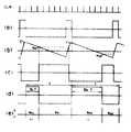
제2도는 제1도의 전력 승산부의 동작을 나타내는 각부 파형도.2 is a waveform diagram of each part showing the operation of the power multiplier of FIG.
제3도는 무효전력 입력부의 상세한 회로도.3 is a detailed circuit diagram of the reactive power input unit.
제4도는 제1도의 기억장치에 내장된 프로그램을 보호하기 위한 회로의 상세도.4 is a detailed diagram of a circuit for protecting a program built in the memory device of FIG.
제5도는 본 발명에 따른 전자식 전력량계의 동작 프로그램을 나타낸 플로우챠트.5 is a flowchart showing an operation program of the electronic electricity meter according to the present invention.
* 도면의 주요부분에 대한 부호의 설명* Explanation of symbols for main parts of the drawings
1 : 전압트랜스 2 : 전류 트랜스1: voltage transformer 2: current transformer
3 : 멀티플렉서 4 : 분주회로3: multiplexer 4: division circuit
4 : 삼각파 발생기 6 : 비교기4: triangle wave generator 6: comparator
7 : 플립플롭 8 : NOR게이트7: flip-flop 8: NOR gate
9 : 적분기 10 : 전원장치9: Integrator 10: Power Supply
11 : 정전검출회로 12 : A/D변환기11: power failure detection circuit 12: A / D converter
13 : 주변 인터페이스 14 : CPU13: peripheral interface 14: CPU
15 : 프로그램 보호회로 16 : 기억장치15: program protection circuit 16: memory device
17 : 숫자 표시부 18 : 클록 발생기17: numeric display unit 18: clock generator
19 : 스위치 블록 20 : 펄스발생회로19: switch block 20: pulse generating circuit
A : 전략량 승산부 B : 디지틀 처리부A: strategic amount multiplication unit B: digital processing unit
가 : 무효전력입력부 ep: 순시전력에 비례하는 전압신호A: Reactive power input part ep : Voltage signal proportional to instantaneous power
본 발명은 전자식 전력량계에 관한 것으로 특히 마이크로프로세서를 이용한 디지틀식 전력량계에 관한 것이다.BACKGROUND OF THE INVENTION 1. Field of the Invention The present invention relates to electronic wattmeters, and more particularly to digital wattmeters using microprocessors.
전자식 전력량계는 기계적인 가동부가 없으므로 주로 기계적 구성으로 되어 있는 유도형 전력량계와 비교해서 경시특성이 우수한 것을 그 장점으로 들수 있다. 즉, 미터의 정확성이 장시간동안 변하지 않고 유지된다. 더욱이 집적회로등으로 회로를 구성하는 것에 의해서 소형화가 가능하며 원격측정이나 컴퓨터와의 인터페이스 등이 용이하다. 이 때문에 종래의 유도형 전력량계를 대신하여 전자식 전력량계가 전력량계의 주류를 이룰 것으로 예상되며, 최근 많은 전자식 전력량계가 개발되고 있다.Electronic electricity meter has no mechanical moving part, and its advantages are superior in time characteristics compared to inductive meter which is mainly composed of mechanical structure. That is, the accuracy of the meter remains unchanged for a long time. Furthermore, by miniaturizing the circuit with integrated circuits, it can be miniaturized, and it is easy to perform telemetry or interface with a computer. For this reason, it is expected that the electronic wattmeter will become the mainstream of the wattmeter in place of the conventional inductive wattmeter, and many electronic wattmeters have been developed recently.
잘 알려진 바와 같이, 종래의 전자식 전력량계는 전력 공급선의 부하전압에 비례하는 전압신호(ev)와 이 전력 공급선의 소모전류에 비례하는 전압신호(ei)를 승산하여 급전선의 순시전력에 비례하는 전압신호 ep=K·ev·ei(단 K는 정수)를 얻는 승산회로와, 이 승산회로의 출력 전압신호(ep)를 적분하여 주파수 신호로 변환하는 전압-주파수 변환회로로 구성되어 있다. 따라서 급전선의 전력량은 상기 전압-주파수 변환회로에서 출력되는 주파수 신호를 디지틀회로로 세어감으로써 구해진다. 이러한 전력량계는 전자식의 장점인 기능의 다양화나 컴퓨터와의 인터에피스에 상당한 제약이 따른다.As is well known, the conventional electronic electricity meter multiplies the voltage signal ev proportional to the load voltage of the power supply line and the voltage signal ei proportional to the consumption current of the power supply line, which is proportional to the instantaneous power of the feeder. A multiplication circuit for obtaining the voltage signal ep = K · ev · ei (where K is an integer), and a voltage-frequency conversion circuit for integrating the output voltage signal ep of the multiplication circuit and converting it into a frequency signal. It is. Therefore, the power amount of the feed line is obtained by counting the frequency signal output from the voltage-frequency conversion circuit into the digital circuit. These meters have significant limitations in the diversification of functions, which are the advantages of electronics, or in inter-epis with computers.
이에 대하여 본 발명은 전력량계의 전력 승산부는 아날로그 회로를 사용하되 이 승산회로의 출력전압신호를 A/D변환기(12)를 통해 마이크로 컴퓨터를 포함한 디지틀 처리부(B)로 입력시키고 그 값에 해당하는 전력을 계산하여 표시하게 하며, 정전시의 대책으로서 전체계산을 위한 프로그램이 저장되어 있는 기억장치를 이용하여 정전시 계산하고 있던 각종 값들을 저장하는 동시에 전력 승산부의 입력단에 무효전력산출회로를 부가하고 출력단에 외부 컴퓨터로의 연결을 위한 직렬 입출력단자와 원격검침용 펄스출력단자를 구비한 다기능의 전자식 전력량계를 제공하는 것을 목적으로 한다.On the other hand, in the present invention, the power multiplier of the wattmeter uses an analog circuit, but inputs the output voltage signal of the multiplier circuit to the digital processing unit B including the microcomputer through the A /
이하 본 발명의 일실시예를 첨부도면에 따라 상세히 설명한다.Hereinafter, an embodiment of the present invention will be described in detail with reference to the accompanying drawings.
제1도는 본 발명에 따른 전자식 전력량계의 전체회로를 나타낸 블록 다이어그램으로서, 크게 나누어 전력승산부(A)와 디지틀처리부(B)로 구성된다.1 is a block diagram showing the entire circuit of the electronic watt-hour meter according to the present invention, which is divided into a power multiplier (A) and a digital processor (B).
전력승산부(A)는 계기의 정확도를 좋게 하기 위해 펄스폭 변조방식을 채용하고 있으며 이 전력 승산부(A)의 구성을 보면 제1도와 같이 3상의 전력선에 접속된 입력단(P1,P2,P3)에 연결되어 부하전압에 비례하는 전압신호(ev1,ev2)를 얻게하는 전압트랜스 PT(1)와 이 급전선의 소모전류에 비례하는 전류신호(i1,i2)를 얻기 위한 전류 트랜스 CT(2)가 설치되고, 후술하는 디지틀 처리부(B)의 클록 발생기(18)로부터의 클록신호(CLK1)를 8분주하여 회로의 동작 기준신호를 공급하는 분주회로(4)와, 상기 전압트랜스(1) 및 전류트랜스(2)에서 검출된 전압 및 전류신호들을 튜티사이클 신호에 비례하여 선택적으로 출력시키는 멀티플렉서(3)와, 상기 분주회로(4)의 출력신호 주기에 따른 삼각파를 발생하기 위한 삼각파 발생기(5)와, 그 하나의 입력단이 삼각파 발생기(5)의 출력단에 연결되고 다른 1입력단이 상기 멀티플렉서(3)의 전압신호출력단(X)에 연결되는 비교기(6)와, 이 비교기의 출력신호와 분주회로(4)의 기준 출력펄스를 조합하여 튜티사이클 신호를 상기 멀티플렉서(3)의 스위칭신호를 공급하는 NOR게이트(8) 및 플립플롭(7)과, 상기 멀티플렉서(3)를 이 스위칭신호에 따라 동작시킴으로써 순시전력에 비례한 전압신호(ep)를 발생시키는 적분회로(9)를 포함하고 있다. 또한 전력 승산부(A)의 입력단에는 전원장치(10)가 연결되어 회로 각부분에 필요한 정전압을 공급하고, 정전시 전압의 하강을 검출하여 마이크로프로세서에 정전 인터럽트신호를 입력시키기 위한 정전검출회로(11)가 부가되어 있다.In order to improve the accuracy of the instrument, the power multiplier A adopts a pulse width modulation method. Referring to the configuration of the power multiplier A, input terminals P1, P2, and P3 connected to three-phase power lines as shown in FIG. Current transformer to obtain a voltage transformer PT (1) which is connected to the power supply voltage (ev1 , ev2 ) which is proportional to the load voltage and a current signal (i1 , i2 ) which is proportional to the current consumption of this feed line. A division circuit 4 for distributing the clock signal CLK1 from the
또한, 제1도의 하반부는 마이크로프로세서를 이용한 디지틀 처리부(B)를 나타내고 있으며, 상기 전력승산부(A)의 적분회로(9)에서 출력되는 순시전력에 비례하는 전압신호(ep)를 디지틀 신호로 변환시켜 주기위한 아날로그/디지탈(A/D)변환기(12)와 이 신호값에 해당하는 전력을 계산하여 표시해 주기위한 CPU(14), 주변 인터페이스(13), 기억장치(16) 및 프로그램 보호회로(15)와 LCD숫자 표시부(17)로 구성되어 있다. 한편 주변 인터페이스(13)의 입력단에는 변성기와 연결하여 사용할 때 편리하게 하기 위하여 합성비 설정용 스위치 블록(19)이 연결되며, 그 출력단에는 원격검침용 출력펄스를 발생하기 위한 펄스발생회로(20)가 접속된다. 또한 CPU(14)의 클록입력단에는 클록발생기(18)가 연결되어 있고, 이CPU(14)의 인터럽트 입력단자 INTR 1에는 상기 정전검출회로(11)의 출력단이 연결되어 있고, 인터럽트단자 INTR 2에는 최대전력용 외부리세트단자가 연결된다.In addition, the lower half of FIG. 1 shows a digital processing unit B using a microprocessor, and the voltage signal ep proportional to the instantaneous power output from the integrating circuit 9 of the power multiplier A is converted into a digital signal. Analog / Digital (A / D)
상기와 같은 본 발명의 전자식 전력량계의 동작을 설명하면 다음과 같다.Referring to the operation of the electronic electricity meter of the present invention as described above.
우선 전력승산부(A)는 펄스폭변조(PWM)방식을 채택하여 정확도를 좋게 하였으며 이 전력승산부(A)의 동작을 나타내는 각부 파형도가 제2도에 도시되었다.First, the power multiplier A adopts a pulse width modulation (PWM) method to improve accuracy, and the waveform diagram of each part representing the operation of the power multiplier A is shown in FIG.
제2도에서, 파형(a)은 튜티사이클이 1/8로서 삼각파 발생기(5)를 동기시키고 있다. 삼각파발생기(5)의 출력전압과 멀티플렉서(3)에서 출력되는 전압신호(ev)를 비교함으로써 나타나는 파형(c)에서 전압신호에 의한 튜티신호파형(d)을 얻을 수 있으며 이 신호와 클럭신호파형(a)를 조합하여 멀티플렉서(3)를 스위칭한다. 즉 멀티플렉서(3)의 출력(X)에는 ep1, ep2중 한개가 연결되며 출력(Y)에는 i1이나 i2가 연결될 수 있는데 연결되는 기간이 제2도의 듀티신호파형(d)과 연관되어 제2도 하단부 그림(e)와 같이 된다. 이렇게 하면 듀티 신호파형(d)에서 D1의 크기는 E-ep1에 비례하고 D2의 크기는 E-e'p2에 비례한다. 따라서 멀티플렉서(3) 출력(Y)에서 평균값

i=1/2k2(ev1+ev2i2) (단, K는 정수)i = 1 / 2k2 (ev1 + ev2 i2 ) (where K is an integer)
가 된다. 따라서 적분기의 출력전압신호(ep)는 전력에 비례하는 값이 된다.Becomes Therefore, the output voltage signal ep of the integrator becomes a value proportional to the power.
여기서 무효전력의 계산은 제3도에 나타낸 바와 같은 무효전력 입력부(가)를 상기 전압트랜스(1)와 멀티플렉서(3)사이에 설치함으로써 가능하다. 제3도의 점선 블록안에 나타낸 무효전력입력부(가)는 전압 위상만을 지연시키고자 한 것으로, 연산증폭기 및 저항기(R), 캐패시터(C)가 조합된 2단 구성으로 되어 있으며, 이 회로의 전류이득을 1이라 했을 때 RC의 값이 작으면 전달함수 G(S)는,The reactive power can be calculated here by providing an reactive power input unit as shown in FIG. 3 between the voltage transformer 1 and the multiplexer 3. The reactive power input unit (A) shown in the dotted line block of FIG. 3 is intended to delay only the voltage phase, and has a two-stage configuration in which an operational amplifier, a resistor (R), and a capacitor (C) are combined. If 1 is RC and the value of RC is small, the transfer function G (S) is

로서 지연기능을 갖게 된다. 이 회로의 2단 직렬구성은 선형구간을 확대시키기 위한 것이다.It has a delay function. The two-stage series configuration of this circuit is to expand the linear section.
본 발명에 의한 디지틀 처리부(B)에서는 마이크로 컴퓨터를 이용하여 전력량에 비례하는 아날로그 신호를 A/D변환기(12)를 통해 읽어 들이고 그 값에 해당하는 전력을 계산하여 표시해주는 동시에 정전시 데이터를 저장하고 프로그램을 보호해주는 역할을 한다.The digital processing unit (B) according to the present invention reads an analog signal proportional to the amount of power through the A /
본 발명의 실시예를 보이는 시스템 블록 다이어그램(제1도)에서 CPU(14)는 인텔사의 8031 싱글칩 마이크로 컴퓨터를 사용하여 주변 인터페이스(13), 기억장치(16) 및 A/D변환기(12)와의 인터페이스를 간단히 하였다.In the system block diagram (FIG. 1) showing an embodiment of the present invention, the
또한 기억장치(16)는 EEPROM 형태의 메모리 소자로 구성되며, 양호하게는 인텔사의 2817을 사용하였다. 이 기억장치(16)에는 전체계산을 위한 프로그램이 저장되어 있는 프로그램 영여과 정전시 계산하고 있던 값들을 저장하기 위한 데이터 영역을 갖게 만든다.In addition, the
CPU(14)와 기억장치(16), 숫자표시부(17) 및 주변 인터페이스(13)는 상호 데이터버스 및 어드레스버스를 통해 연결되고, 여기서 CPU(14)와 기억장치(16)사이에는 프로그램 보호회로(15)가 설치되어 후술하는 바와 같은 기억장치(16)에 내장된 프로그램을 보호하는 기능을 갖게 된다.The
상기 프로그램 보호회로(15)의 상세한 구성은 제4도의 나타낸 것과 같이 CPU(14)의 최상위 어드레스출력단(A11)을 분기하여 NAND게이트(G2)의 1입력단으로 연결하고 CPU(14)의 라이트단자(WR)를 인버어터(G1)를 통해 상기 NAND게이트(G2)의 다른 1입력단으로 연결시켜 이 게이트(G2)의 출력단이 기억장치(16)이 라이트단자(WR)로 연결되게 한 것이다. 즉, 어드레스라인(A11)의 논리헤벨이 "0"이면 메모리의 프로그램영역을 액세스하고 이 어드레스라인(A11)의 논리신호가 "1"이면 데이터 영역을 액세스하도록 설정되어 있다고 할 때, 어드레스라인(A11)에 논리 "0"의 신호가 나타나면 게이트 G1및 G2의 조합에 의한 출력신호가 기억장치(16)의 라이트단자(WR)를 동작 디스에이블 상태로 만들어 프로그램 영역의 액세스시에 쓰기동작을 할수 없게 됨으로써 이 기억장치(16)내에 기억된 프로그램을 보호할 수 있게 된다.다시말해 본 발명의 전자식 전력량계는 상기한 기억장치(16)와 프로그램 보호회로(15)에 의해 프로그램과 데이터를 공유할 수 있는 것으로 프로그램용 ROM(판독전용 기억장치)과 정전시 데이터 저장용 NOV RAM(등속호출기억장치)을 별도로 두어야 했던 불편함을 제거하였으며, 본 발명의 정전시 데이터 기억 및 계산 프로그램은 제5도의 플로우챠트에 나타내었다.The detailed configuration of the program protection circuit 15 is divided into the uppermost address output terminal A11 of the
한편, 제1도에 나타낸 숫자 표시부(17)는 전력소모를 줄이고 5자리 십진수를 표시하기 위하여 5자리 LCD를 사용하였으며 LCD의 구동을 위하여 구동용 집적회로를 사용하였다.Meanwhile, the numeric display unit 17 shown in FIG. 1 uses a 5-digit LCD to reduce power consumption and display 5-digit decimal numbers, and uses a driving integrated circuit to drive the LCD.
본 발명의 전자식 전력량계에서 CPU(14)와 기억장치(16)에서 수행되는 정전 인터럽트 처리 및 전력량 적산 및 표시프로그램을 제5도의 플로우챠트에 의거하여 설명한다. 우선, 정전발생시 정전검출회로(11)에서 정전 인터럽트신호(S1)가 발생되며, 이 인터럽트신호(S1)가 CPU(14)의 INTR1 단자로 공급되면 이 인터럽트는 최우선으로 처리된다.The electrostatic interrupt processing and the power amount integration and display program performed by the
제5도에서, 전략량계에 전원이 인가되면, 단계 101에서 정전인터럽트 신호가 있는지를 검사하고, 정전인터럽트가 발생하였다면 현재 전력량의 첫 번째 데이터를 저장할 기억장치의 주소와 데이터가 있는 레지스터가 지정되고 레지스터의 내용을 기억장치의 지정된 주소에 기입한다(단계 104). 이때 기억장치(16)는 쓰기모우드가 되기 때문에 CPU(14)는 자동적으로 리세트된다. 이 CPU(14)가 리세트될 때 CPU(14)내의 레지스터들은 원래의 값을 보존하고, CPU(14)의 프로그램카운터가 0000번지로 리세트된다.In FIG. 5, when power is supplied to the strategic meter, it is checked in step 101 whether there is a power interruption signal, and if a power interruption occurs, an address of a storage device to store the first data of the current power amount and a register containing data are designated. The contents of the register are written to the designated address of the storage device (step 104). At this time, since the
단계 101에서 104의 과정중에 1바이트의 데이터가 기입된후 CPU(14)의 리세트조건을 검사하여 정전 인터럽트에 의한 것이 확인되면 다음 데이터를 기입하는 루틴이 수행된다.If one byte of data is written in the process of steps 101 to 104, and the reset condition of the
이와 같은 과정을 반복하여 마지막 데이터를 쓰고난다음 단계 105에서 전원이 다시 온되었는가를 검사하게 되고 전원이 온 되지 않았다면 CPU(14)는 동작을 멈춘 상태에서 결국 정전에 의해 전원공급이 중지된다. 반면에 전원이 온되면 프로그램의 시작위치로 복귀하여 단계 106 내지 단계 111의 전력량 표시과정을 수행하게 된다.After repeating the above process and writing the last data, it is checked in
단계 106에서, 외부스위치블록에 의해 설정된 값들을 읽어들이고 나서 CPU(14)의 적산 레지스터를 초기화 시킨다. 그다음 단계 107에서 기억장치에 기억되었던 데이터를 레지스터에 로드시키고, 단계 108에서 A/D변환기(12)를 통해 입력된 적분기의 출력전압의 독출 및 전력을 환산하고, 단계 109에서 전력량을 적산하게 되며, 단계 110에서 현재의 전력량 또는 최대전력량을 표시하게 되는데 최대전력의 계산은 A/D변환기(12)를 통해 받아들인 데이터를 전력으로 환산하고 기억하고 있는 최대 전력값과 비교하여 현재의 전력이 더 클 경우 최대 전력값을 현재의 전력으로 바꾸어 기억시킨다. 전력량과 최대전력걍은 교대로 표시되며, 예를 들어 전력량은 10초동안 최대전력은 5초동안 표시된다. 여기서 어느 일정 기간동안 기억되어 있는 최대전력값은 외부 리세트신호(CPU의 INTR 2에 가해짐)에 의하여 0으로 만들 수 있으므로 일정기간의 최대 수요전력을 표시하게 할 수 있다. 또한 단계 111에서 전력량에 해당하는 펄스를 출력시켜 원격검침을 가능하게 만든다.In
이상 설명한 바와 같이 본 발명의 전자식 전력량계에 의하면 전력량 승산부(A)에서 구해진 출력전압신호를 마이크로 프로세서를 이용한 디지틀 처리부(B)에 입력시켜 전력양을 적산하게 하고 이 전력량 및 최대 수요전력을 디지틀 표시부(B)에 표시하게 함과 동시에 정전대책으로서 전력량 계산을 위한 프로그램이 내장되어 있는 기억장치를 이용하여 계산하고 있던 각종 값들을 기억시킬 수 있고, 또 전력량 승산부(A)의 입력단에 무효전력 산출회로를 부가하면 무효전력량계로 사용할 수 있으며, 전력량계 외부의 컴퓨터로 연결사용을 위한 직렬 입출력 단자와 원격 검침용 펄스출력단자를 가질 수 있으므로 산업용 전분야에서 사용할 수 있고 다기능을 갖는 전자식 전력량계를 제공할 수 있는 특출한 효과가 있다.As described above, according to the electronic watt-hour meter of the present invention, the output voltage signal obtained from the power multiplier A is input to the digital processing unit B using a microprocessor to integrate the power amount, and the power amount and the maximum demand power are displayed in the digital display unit. As shown in (B), as a countermeasure against power failure, various values that have been calculated can be stored by using a storage device having a program for calculating the amount of power, and a reactive power is calculated at the input of the power multiplier A. By adding a circuit, it can be used as a reactive wattmeter, and it can have a serial input / output terminal and remote meter reading pulse output terminal for connection to a computer outside the wattmeter, so that it can be used in all industrial fields and can provide an electronic wattmeter with multifunction. That has an exceptional effect.
Claims (3)
Translated fromKoreanPriority Applications (1)
| Application Number | Priority Date | Filing Date | Title |
|---|---|---|---|
| KR1019870003407AKR900000983B1 (en) | 1987-04-10 | 1987-04-10 | Electronic electricity meter |
Applications Claiming Priority (1)
| Application Number | Priority Date | Filing Date | Title |
|---|---|---|---|
| KR1019870003407AKR900000983B1 (en) | 1987-04-10 | 1987-04-10 | Electronic electricity meter |
Publications (2)
| Publication Number | Publication Date |
|---|---|
| KR880013018A KR880013018A (en) | 1988-11-29 |
| KR900000983B1true KR900000983B1 (en) | 1990-02-23 |
Family
ID=19260650
Family Applications (1)
| Application Number | Title | Priority Date | Filing Date |
|---|---|---|---|
| KR1019870003407AExpiredKR900000983B1 (en) | 1987-04-10 | 1987-04-10 | Electronic electricity meter |
Country Status (1)
| Country | Link |
|---|---|
| KR (1) | KR900000983B1 (en) |
Cited By (1)
| Publication number | Priority date | Publication date | Assignee | Title |
|---|---|---|---|---|
| KR101153504B1 (en)* | 2010-09-30 | 2012-06-12 | 한국전력공사 | Electronic watt-hour meter managing multiple input signal and method of calculating watt-hour |
- 1987
- 1987-04-10KRKR1019870003407Apatent/KR900000983B1/ennot_activeExpired
Cited By (1)
| Publication number | Priority date | Publication date | Assignee | Title |
|---|---|---|---|---|
| KR101153504B1 (en)* | 2010-09-30 | 2012-06-12 | 한국전력공사 | Electronic watt-hour meter managing multiple input signal and method of calculating watt-hour |
Also Published As
| Publication number | Publication date |
|---|---|
| KR880013018A (en) | 1988-11-29 |
Similar Documents
| Publication | Publication Date | Title |
|---|---|---|
| US5548209A (en) | Solid state electric power usage meter and method for determining power usage | |
| US4365302A (en) | High accuracy AC electric energy metering system | |
| US9448263B2 (en) | Power quality monitoring apparatus for railway power system | |
| RU2126974C1 (en) | Method of electronic measurement of electric energy and device for its realization (variants) | |
| US4229795A (en) | Electronic maximum measuring device | |
| GB2327274A (en) | Commodity consumpton meter | |
| KR900000983B1 (en) | Electronic electricity meter | |
| JP2968607B2 (en) | Reactive energy meter | |
| US5146157A (en) | Calculation apparatus for an electronic meter | |
| JP3056046B2 (en) | Small power consumption measuring device | |
| Kingston et al. | Multi function polyphase metering-an integrated approach | |
| JP3366291B2 (en) | Microcomputer | |
| JPH06207955A (en) | π / 2 phase shift circuit, and reactive energy meter and composite meter using the same | |
| CN211061647U (en) | Automatic detection device for mV (modified mV) to mA (metal oxide) module | |
| JPS6315628A (en) | Maximum demanded power monitoring system for transactions | |
| JPS61260120A (en) | Electronic integrating instrument | |
| JP2925443B2 (en) | Electronic measuring instrument | |
| JPH05133987A (en) | Electronic electricity meter | |
| KR100290113B1 (en) | Telemetering control unit | |
| KR0157644B1 (en) | Data control method of watt hour meter | |
| KR940009290B1 (en) | Electric signal rise and fall time measuring device | |
| KR0128141Y1 (en) | Power supply complex apparatus with data reset function | |
| Markow | Microcontroller-based energy metering using the AD7755 | |
| JPH0755854A (en) | Integrating meter | |
| JPS5952324A (en) | Detecting circuit for service interruption and its recovery |
Legal Events
| Date | Code | Title | Description |
|---|---|---|---|
| A201 | Request for examination | ||
| PA0109 | Patent application | Patent event code:PA01091R01D Comment text:Patent Application Patent event date:19870410 | |
| PA0201 | Request for examination | Patent event code:PA02012R01D Patent event date:19870410 Comment text:Request for Examination of Application | |
| PG1501 | Laying open of application | ||
| E902 | Notification of reason for refusal | ||
| PE0902 | Notice of grounds for rejection | Comment text:Notification of reason for refusal Patent event date:19890906 Patent event code:PE09021S01D | |
| G160 | Decision to publish patent application | ||
| PG1605 | Publication of application before grant of patent | Comment text:Decision on Publication of Application Patent event code:PG16051S01I Patent event date:19900124 | |
| E701 | Decision to grant or registration of patent right | ||
| PE0701 | Decision of registration | Patent event code:PE07011S01D Comment text:Decision to Grant Registration Patent event date:19900518 | |
| GRNT | Written decision to grant | ||
| PR0701 | Registration of establishment | Comment text:Registration of Establishment Patent event date:19900712 Patent event code:PR07011E01D | |
| PR1002 | Payment of registration fee | Payment date:19900712 End annual number:3 Start annual number:1 | |
| PR1001 | Payment of annual fee | Payment date:19921207 Start annual number:4 End annual number:4 | |
| PR1001 | Payment of annual fee | Payment date:19931224 Start annual number:5 End annual number:5 | |
| PR1001 | Payment of annual fee | Payment date:19941229 Start annual number:6 End annual number:6 | |
| PR1001 | Payment of annual fee | Payment date:19951228 Start annual number:7 End annual number:7 | |
| PR1001 | Payment of annual fee | Payment date:19961226 Start annual number:8 End annual number:8 | |
| PR1001 | Payment of annual fee | Payment date:19971227 Start annual number:9 End annual number:9 | |
| PR1001 | Payment of annual fee | Payment date:19981228 Start annual number:10 End annual number:10 | |
| PR1001 | Payment of annual fee | Payment date:19991223 Start annual number:11 End annual number:11 | |
| PR1001 | Payment of annual fee | Payment date:20001227 Start annual number:12 End annual number:12 | |
| PR1001 | Payment of annual fee | Payment date:20020103 Start annual number:13 End annual number:13 | |
| PR1001 | Payment of annual fee | Payment date:20030103 Start annual number:14 End annual number:14 | |
| PR1001 | Payment of annual fee | Payment date:20031229 Start annual number:15 End annual number:15 | |
| PR1001 | Payment of annual fee | Payment date:20050110 Start annual number:16 End annual number:16 | |
| PR1001 | Payment of annual fee | Payment date:20060105 Start annual number:17 End annual number:17 | |
| FPAY | Annual fee payment | Payment date:20061228 Year of fee payment:18 | |
| PR1001 | Payment of annual fee | Payment date:20061228 Start annual number:18 End annual number:18 | |
| EXPY | Expiration of term | ||
| PC1801 | Expiration of term |