KR900000041B1 - Washing machine - Google Patents
Washing machineDownload PDFInfo
- Publication number
- KR900000041B1 KR900000041B1KR1019860004784AKR860004784AKR900000041B1KR 900000041 B1KR900000041 B1KR 900000041B1KR 1019860004784 AKR1019860004784 AKR 1019860004784AKR 860004784 AKR860004784 AKR 860004784AKR 900000041 B1KR900000041 B1KR 900000041B1
- Authority
- KR
- South Korea
- Prior art keywords
- circuit
- washing
- signal
- state
- output
- Prior art date
- Legal status (The legal status is an assumption and is not a legal conclusion. Google has not performed a legal analysis and makes no representation as to the accuracy of the status listed.)
- Expired
Links
Images


Classifications
- D—TEXTILES; PAPER
- D06—TREATMENT OF TEXTILES OR THE LIKE; LAUNDERING; FLEXIBLE MATERIALS NOT OTHERWISE PROVIDED FOR
- D06F—LAUNDERING, DRYING, IRONING, PRESSING OR FOLDING TEXTILE ARTICLES
- D06F34/00—Details of control systems for washing machines, washer-dryers or laundry dryers
- D06F34/08—Control circuits or arrangements thereof
- D—TEXTILES; PAPER
- D06—TREATMENT OF TEXTILES OR THE LIKE; LAUNDERING; FLEXIBLE MATERIALS NOT OTHERWISE PROVIDED FOR
- D06F—LAUNDERING, DRYING, IRONING, PRESSING OR FOLDING TEXTILE ARTICLES
- D06F33/00—Control of operations performed in washing machines or washer-dryers
- D06F33/30—Control of washing machines characterised by the purpose or target of the control
- D06F33/32—Control of operational steps, e.g. optimisation or improvement of operational steps depending on the condition of the laundry
- D—TEXTILES; PAPER
- D06—TREATMENT OF TEXTILES OR THE LIKE; LAUNDERING; FLEXIBLE MATERIALS NOT OTHERWISE PROVIDED FOR
- D06F—LAUNDERING, DRYING, IRONING, PRESSING OR FOLDING TEXTILE ARTICLES
- D06F34/00—Details of control systems for washing machines, washer-dryers or laundry dryers
- D06F34/14—Arrangements for detecting or measuring specific parameters
- D—TEXTILES; PAPER
- D06—TREATMENT OF TEXTILES OR THE LIKE; LAUNDERING; FLEXIBLE MATERIALS NOT OTHERWISE PROVIDED FOR
- D06F—LAUNDERING, DRYING, IRONING, PRESSING OR FOLDING TEXTILE ARTICLES
- D06F39/00—Details of washing machines not specific to a single type of machines covered by groups D06F9/00 - D06F27/00
- D06F39/02—Devices for adding soap or other washing agents
- D—TEXTILES; PAPER
- D06—TREATMENT OF TEXTILES OR THE LIKE; LAUNDERING; FLEXIBLE MATERIALS NOT OTHERWISE PROVIDED FOR
- D06F—LAUNDERING, DRYING, IRONING, PRESSING OR FOLDING TEXTILE ARTICLES
- D06F39/00—Details of washing machines not specific to a single type of machines covered by groups D06F9/00 - D06F27/00
- D06F39/08—Liquid supply or discharge arrangements
- D06F39/087—Water level measuring or regulating devices
- D—TEXTILES; PAPER
- D06—TREATMENT OF TEXTILES OR THE LIKE; LAUNDERING; FLEXIBLE MATERIALS NOT OTHERWISE PROVIDED FOR
- D06F—LAUNDERING, DRYING, IRONING, PRESSING OR FOLDING TEXTILE ARTICLES
- D06F2101/00—User input for the control of domestic laundry washing machines, washer-dryers or laundry dryers
- D06F2101/10—Spin speed
Landscapes
- Engineering & Computer Science (AREA)
- Textile Engineering (AREA)
- Control Of Washing Machine And Dryer (AREA)
Abstract
Translated fromKoreanDescription
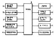
Translated fromKorean제1도는 본 발명에 따른 전자동 센서세탁기의 블럭도.1 is a block diagram of a fully automatic sensor washing machine according to the present invention.
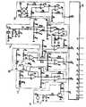
제2a, b도는 상기 제4도의 블럭도의 일실시예의 구체 회로도.2a and b are detailed circuit diagrams of one embodiment of the block diagram of FIG.
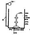
제3a, b도는 본 발명에 따른 각센서의 취부도.3a, b is a mounting view of the angle sensor according to the present invention.
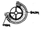
제4a, b, c도는 도르레(D-pulley)의 마그네트 취부도 및 도르레의 관성회전 상태도.4a, b, and c are diagrams showing the magnet mounting of the pulley (D-pulley) and the inertia rotation state of the pulley.
제5도는 세제투입장치도.5 is a detergent dosing device.
제6도는 상기 제2도의 급수상태 검지회로의 출력특성도.6 is an output characteristic diagram of the water supply state detection circuit of FIG.
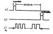
제7도는 상기 제2도의 세탁략 검지회로의 출력파형도.7 is an output waveform diagram of the laundry detection detection circuit of FIG.
제8도는 상기 제2도의 세정헹굼상태 검지회로의 출력특성도.8 is an output characteristic diagram of the cleaning rinse state detection circuit of FIG.
제9도는 상기 제2도의 동작흐름도.9 is a flowchart of operation of FIG.
* 도면의 주요부분에 대한 부호의 설명* Explanation of symbols for main parts of the drawings
1 : 전원회로 2 : 키조작 입력회로1: power supply circuit 2: key operation input circuit
3 : 급수상태 검지회로 4 : 세탁략 검지회로3: Water supply state detection circuit 4: Laundry scheme detection circuit
5 : 주위온도 검지회로 6 : 세정헹굼상태 검지회로5: Ambient temperature detection circuit 6: Cleaning rinse state detection circuit
7 : 탈수상태 검지회로 8 : 제어회로7: Dehydration state detection circuit 8: Control circuit
9 : 솔레노이드 구동회로 10 : 세제투입 구동회로9
11 : 표시회로11: display circuit
본 발명은 전자동 세탁기에 관한 것으로, 특히 센서를 이용하여 세탁상태에 따라 진행점이 자동으로 진행되는 전자동 센서세탁기에 관한 것이다.The present invention relates to a fully automatic washing machine, and more particularly, to a fully automatic sensor washing machine in which a progress point automatically proceeds according to a washing state using a sensor.
종래의 전자동 세탁기에 있어서는 사용자가 세탁을 할때 세제를 대략적으로 세탁조에 투입하고, 세탁량에 대한 수위를 설정한 세탁물의 오염상태에 따라 오염이 많은 세탁코스 또는 오염이 적은 세탁코스를 설정한 후 시간제어 방식에 의해 동작하여 왔다. 그러나 상기와 같은 동작하는 세탁기는 첫째로 세탁량에 대한 적정한 세제를 투입할 수 없었으며, 둘째로 세탁조 내의 급수자체에도 세제 및 세탁량에 대한 급수 설정이 되지 않았으며, 셋째로 세탁 및 탈수행정에 있어서 세탁의 오염상태와 세탁물의 종류에 따라 사용자가 일정한 시간을 설정하여 진행시키므로서 세정이 완전히 되지 않았는데 다음 행정으로 넘어가는 문제점과 세정이 완료되었는데도 설정된 시간까지 계속 반복되는 경우가 있었으며, 넷째로 헹굼행정에서도 비눗물이 완전히 빠지지 않은 상태에서 자기행정은 진행하는 사례 및 헹굼이 완료되고도 물을 소비하는 문제가 있었다. 또한 탈수행정에 있어서도 시간제어로서 탈수기능을 제어함으로서 탈수가 완전히 되지 않았을 때 끝나는 경우와 탈수가 완료된후에 탈수 행정을 계속함으로서 옷의 마모가 있는 문제가 있었다.In the conventional fully automatic washing machine, when the user washes, the detergent is roughly put into the washing tank, and after setting a washing course with a lot of contamination or a washing course with little contamination according to the contamination state of the laundry that sets the level of the washing amount, It has been operated by the control method. However, the washing machine operating as described above could not first put an appropriate detergent for the washing amount, and secondly, the water supply for the detergent and the washing amount was not set in the water supply itself in the washing tank, and third, the washing in the washing and dehydrating administration. According to the contamination status of the laundry and the type of laundry, the user did not complete the cleaning by setting a certain time, but the problem of moving to the next stroke and the cleaning were completed, but it was repeated until the set time. Self-administration in the state that the soapy water is not completely drained and there was a problem of consuming water even when the rinsing is completed. In addition, in the dehydration administration, there was a problem in that there was a problem of wear of clothes by controlling the dehydration function as a time control and ending when the dehydration was not completed and continuing the dehydration stroke after the dehydration was completed.
따라서 본 발명의 목적은 세탁상태에 따라 제어되는 전자동 센서세탁기를 제공함에 있다.It is therefore an object of the present invention to provide a fully automatic sensor washing machine controlled according to the washing conditions.
본 발명의 다른 목적은 세정 및 헹굼상태를 검지할 수 있는 회로를 제공함에 있다.Another object of the present invention is to provide a circuit capable of detecting a cleaning and rinsing state.
본 발명의 또 다른 목적은 세탁량을 검지하여 이에 대응하는 세제를 자동으로 공급할 수 있도록 한 회로를 제공함에 있다.Still another object of the present invention is to provide a circuit for detecting a washing amount and automatically supplying a detergent corresponding thereto.
본 발명의 또다른 목적은 탈수상태를 검지할 수 있는 회로를 제공함에 있다.Still another object of the present invention is to provide a circuit capable of detecting a dehydration state.
상기 목적을 달성하기 위한 본 발명은 교류전원을 입력하여 일정 직류전압으로 정류출력하는 전원회로와, 소정의 신호를 키 압압으로 출력하는 키조작 입력회로와, 세탁조 내의 수위를 검지하여 수위량에 대한 소정의 신호를 출력하는 급수상태 검지회로와, 세탁조 내의 세탁량을 체크하여 이에 대응하는 펄스신호를 출력하는 세탁량 검지회로와, 주위온도를 검지하여 주위온도에 대응하는 소정의 신호를 출력하는 주위온도 검지회로와, 세정 및 헹굼상태를 검지하여 탈수상태의 신호를 출력하는 탈수상태 검지회로와, 상기 전원회로와 키조작 입력회로와 급수상태 검지회로와 세탁량 검지회로와 주위온도 검지회로와 세정헹굼 검지회로와 탈수상태 검지회로에서 출력되는 각각의 상태신호를 입력하여 이를 판단하고 세제투입신호와 현재의 진행표시 및 모터 및 배수, 급수변의 솔레노이드 구동신호를 각각 출력하는 제어회로와, 상기 제어회로에서 출력되는 솔레노이드 구동신호를 입력하여 급수변과 배수변 및 회전익을 구동시키는 솔레노이드 구동회로와, 상기 제어회로에서 출력되는 세제 투입 신호를 입력하여 이에 대응하는 시간동안 세제투입 모터를 구동하는 세제투입 구동회로와, 상기 제어회로에서 출력되는 현재 진행표시를 입력하여 진행과정을 디스플레이하는 표시회로로 구성함을 특징으로 한다.The present invention for achieving the above object is a power supply circuit for rectifying and outputting a constant DC voltage by inputting an AC power supply, a key operation input circuit for outputting a predetermined signal to the key pressure, and detects the water level in the washing tank for the water level A water supply state detection circuit that outputs a predetermined signal, a laundry amount detection circuit that checks the amount of washing in the washing tank and outputs a pulse signal corresponding thereto, and an ambient temperature detection that detects the ambient temperature and outputs a predetermined signal corresponding to the ambient temperature Circuit, a dehydration state detection circuit that detects the washing and rinsing state and outputs a dehydration state signal, the power supply circuit, the key operation input circuit, the water supply state detection circuit, the laundry amount detection circuit, the ambient temperature detection circuit and the washing rinsing detection circuit And input each status signal outputted from the dehydration state detection circuit and input the detergent input signal and the current progress table. And a control circuit for outputting a solenoid driving signal of a motor, a drain, and a water supply side, a solenoid driving circuit for inputting a solenoid driving signal output from the control circuit to drive a water supply side, a drainage side, and a rotor blade, and an output from the control circuit. And a detergent input driving circuit for driving the detergent input motor for a corresponding time by inputting the detergent input signal, and a display circuit for displaying the progress by inputting a current progress indication output from the control circuit. .
이하 본 발명을 첨부한 도면을 참조하여 상세히 설명한다.Hereinafter, the present invention will be described in detail with reference to the accompanying drawings.
제1도는 본 발명에 따른 전자동 센서세탁기의 블럭도로서, 교류전원을 입력하여 일정직류전압으로 정류출력하는 전원회로(1)와, 소정의 행위신호를 키의 조작으로 출력하는 키조작 입력회로(2)와, 세탁조 내의 수위를 검지하여 수위량에 대한 소정신호를 출력하는 급수상태 검지회로(3)와, 세탁조 내의 회전익이 회전할때 마그네트 센서로 세탁량을 검지하여 이에 대응하는 펄스를 출력하는 세탁량 검지회로(4)와, 온도센서로 주위온도를 검지하여 소정신호를 출력하는 주위온도 검지회로(5)와, 세정 및 헹굼상태를 광센서로 검지하여 이에 대응하는 신호를 출력하는 세정헹굼상태 검지회로(6)와, 세탁조가 회전할때 탈수(쇼크)센서로 세탁물의 탈수상태를 검지하여 탈수상태 신호를 출력하는 탈수상태 검지회로(7)와, 상기 전원회로(1)에서 출력되는 정류된 일정의 전압과 키조작 입력회로(2)에서 출력되는 소정 행위의 키입력신호와 급수상태 검지회로(3)에서 출력되는 수위검지신호와 세탁량 검지회로(4)에서 출력되는 세탁량 측정신호와 주위온도 검지회로(5)에서 출력되는 온도 검지신호와 세정헹굼상태 검지회로(6)에서 출력되는 세정 또는 헹굼상태 검지신호와 탈수상태 검지회로(7)에서 출력되는 탈수상태 검지신호를 각각 입력하여 전행정 상황을 판단하여 세제 주입신호의 현재 진행표시신호 및 솔레노이드 구동신호 출력하는 제어회로(8)와, 상이 제어회로(8)에서 출력되는 솔레노이드 구동신호를 입력하여 급수변과 배수변 및 회전익을 구동시키는 솔레노이드 구동회로(9)와, 상기 제어회로(8)에서 출력되는 세제투입신호를 입력 이에 대응하는 시간동안 세제를 투입하는 모터를 구동시키는 세제투입 구동회로(10)와, 상기 제어회로(8)에서 출력되는 현재 진행신호를 입력하여 이에 대응하는 진행과정을 디스플레이하는 표시회로(11)로 구성된다.1 is a block diagram of a fully automatic sensor washing machine according to the present invention, comprising: a
따라서 전원회로(1)에서 각 회로에 직류전원을 공급하는 상태하에 키조작 입력회로(2)에서 일정행위의 신호(세탁시작키)가 출력하여 제어회로(8)에 입력되면, 상기 제어회로(8)은 시작신호라고 인식후 급수변을 여는(Open)신호를 솔레노이드 구동회로(9)로 출력한다. 이때 상기 제어회로(8)에서 출력되는 신호 즉 급수변 "온"신호를 입력한 솔레노이드 구동회로(9)는 급수변을 구동하여 세탁조 내에 급수를 시작한다.Therefore, when the
상기 솔레노이드 구동회로(9)가 급수변을 열어 세탁조 내에 들어오는 수위량을 급수상태 검지회로(3)가 검지하여 급수량상태 신호로 제어회로(8)로 출력하며, 상기 제어회로(8)는 상기 급수상태 검지회로(3)에서 출력되는 금수량상태 신호를 입력하여 소량급수인가를 판단후 소량 급수인 경우 솔레노이드 구동회로(9)로 회전익 구동신호를 출력한다. 그러므로 솔레노이드 구동회로(9)는 회전익을 구동시키며, 이로 인해서 세탁량 검지회로(4)는 세탁량을 측정하여 투입세탁량에 대한 펄스를 출력하여 제어회로(8)로 출력한다. 이때 상기 세탁량 검지회로(4)에서 출력되는 펄스신호를 입력한 제어회로(8)는 펄스를 카운트하여 현재 세탁조 내의 수위가 세탁량에 대한 적절한 급수인가를 판단하여 측정한 수위로 조절한다.The
한편, 주위온도 검지회로(5)는 온도센서로 주위온도변화를 검지하여 이에 대응하는 소정신호를 제어회로(8)로 출력하며, 제어회로(8)는 상기 주위온도 검지회로(5)에서 출력되는 온도신호에 대응하는 최적의 시간동안 소정의 신호를 세제투입 구동회로(10)로 출력하여 액체세제를 세탁조 내에 투입시키며, 세제주입이 끝나는 동시에 제어회로(8)는 회전익(모터) 구동신호를 솔레노이드 구동회로(9)로 출력한다.Meanwhile, the ambient
이때 주위온도를 검지하여 액체 세제를 세탁조내에 투입시키는 이유는 액체세제는 온도에 따라 점도가 다르기 때문에 액체세제의 투입은 온도변화가 큰 요인이 되기 때문이다. 따라서 세탁조 내에는 세정행정이 실시됨과 동시에 세정헹굼 검지회로(6)는 세탁조 내의 오염된 혼탁수를 광센서로 검지하여 어느 한개(정도)의 혼탁수가 되면 세정이 완료되었다는 신호를 제어회로(8)로 출력한다.At this time, the reason why the liquid detergent is introduced into the washing tank by detecting the ambient temperature is because the liquid detergent has a different viscosity depending on the temperature. Therefore, while the washing operation is performed in the washing tank, the washing and rinsing detection circuit 6 detects the contaminated turbid water in the washing tank with an optical sensor, and when the any of the turbid water is washed, the
이에 상기 세정헹굼 검지회로(6)에서 출력되는 세정 완료신호를 입력한 제어회로(8)는 솔레노이드 구동회로(9)로 일정신호를 출력하여 세탁조 내에 있는 오염된 물을 배수시키며, 급수상태 검지회로(3)에서 급수상태를 검지후 배수완료 신호를 제어회로(8)로 출력한다. 제어회로(8)는 솔레노이드 구동회로(9)로 세탁조를 회전시킬 신호를 출력시키므로서 세탁물의 탈수는 개시된다. 또한 상기 세탁물의 탈수상태는 탈수상태 검지부(7)에서 검지된 후 제어회로(8)로 탈수가 적절히 되었다는 신호를 제어회로(8)로 출력된다.The
따라서 상기 제어회로(8)는 솔레노이드 구동회로(9)로 소정의 신호 즉, 급수변의 오프신호를 출력하여 급수를 시작하여, 상기 급수상태는 급수상태 검지회로(3)에서 전술한 바와 같이 수위를 체크한 0후 급수가 완료되면 제어회로(8)에서 솔레노이드 구동회로(9)로 회전익을 구동할 수 있는 신호를 출력하여 헹굼을 실시한다.Therefore, the
이때 상기 헹굼행정은 세정헹굼 검지회로(7)에서 헹굼의 상태를 검지하여 헹굼상태 신호를 제어회로(8)로 출력하며, 제어회로(8)는 상기 헹굼상태신호를 입력하여 헹굼이 완료된 것이라고 판단하고 솔레노이드 구동회로(9)로 배수변을 오픈시킬 신호를 출력하여 세탁조 내에 있는 물을 배수시킨다.At this time, the rinsing stroke detects the rinsing state in the washing rinsing detection circuit 7 and outputs a rinsing state signal to the
상기 배수검지는 전술한 바와 같이 배수상태 검지회로(3)에서 행하여 배수완료시 제어회로(8)로 배수 수위 상태 신호를 출력한다. 또한 상기 제어회로(8)는 급수상태 검지회로(3)에서 출력되는 세탁조를 회전시키어 탈수행정에 들어가며, 이때의 탈수행정은 탈수상태 검지회로(7)에서 검지하여 탈수 완료시 탈수 완료신호를 제어회로(8)로 출력한다. 이때 표시회로(11)는 상기 각 회로의 동작상황을 디스플레이하며, 제어회로(8)의 동작 진행 표시신호를 받아 동작한다. 따라서 제어회로(8)는 상기 탈수상태 검지회로(7)에서 탈수완료 신호를 입력하여 모든 행정을 종료한다.The drainage detection is performed in the drainage
제2도는 제1도의 블럭도의 일실시예의 구체회로도로서, 교류전원스위티(SW1)와 트랜스(T), 브리지 다이오드(BD1)와 캐패시터(C1-C2)와 레귤레이터(100)로 구성된 회로가 전원회로(1)에 대응하며, 저항(R3-R5)와 캐패시터(C3-C4)와 스타트스위치(SW2)와 세탁조 문스위치(SW3)로 구성된 회로가 키조작 입력회로(2)에 대응하고, 저항(R6-R10)와 입력센서(SN1)와 연산증폭기(OP9-OP10)으로 구성된 회로가 급수상태 검지회로(3)에 대응하고, 저항(R11-R12)와 다이오드(D1)와 캐패시터(C5)와 마그네틱센서(Magnet Senser)(SN2)와 트랜지스터(Q1)으로 구성된 회로가 세탁량 검지회로(4)에 대응하며, 저항(R13-R17)와 정특성 더어미스터(SN5)와 연산증폭기(OP1-OP2)로 구성된 회로가 주위온도 검지회로(5)에 대응하고, 저항(R18-R23)광 인터럽트검지기(Poto Interrupt Senser : 이하 광센서라 칭함)(SN3)와 연산 증폭기(OP3-OP4)로 구성된 회로가 세정헹굼 검지회로(6)에 대응하며, 저항(R24-R35)와 캐패시터(C6-C7)와 다이오드(D2-D4)와 쇼크센서(Shock Senser) (SN4)와 연산증폭기(OP5-OP8)로 구성된 회로가 탈수상태 검지회로(7)에 대응하고, 저항(R26-R39)와 인버터(INV1-INV4)와 트라이악(TRLAC : 이하 SCR이라함)(SCR2-SCR5)와 회전익 솔레노이드(MR,ML)와 배수변(DV) 급수변(MV)로 구성된 회로가 솔레노이드 구동회로(9)에 대응하며, 저항(R1-R2)와 SCR1와 포트 트라이악(Poto TRLAC)(101)과 브리지다이오드(BD2)와 직류모터(K)로 구성된 회로가 세제투입 구동회로(10)에 대응하고, 저항(R40-R45)와 인버터(INV5- INV10)와 발광다이오드(LED1-LED6)로 구성된 회로가 표시회로(11)에 대응하며, 상기 회로의 동작되는 상태를 제어판단 하기위한 제어회로(8)로 구성된다.FIG. 2 is a specific circuit diagram of an embodiment of the block diagram of FIG. 1, wherein a circuit composed of an AC power supply SW1 and a transformer T, a bridge diode BD1, a capacitor C1-C2, and a
한편, 제3a,b도는 본 발명에 따른 각 센서의 취부도이며, 제4a,b,c도는 도르레(D-Pulley)의 마그네트(Magnet) 2a 취부도 및 도르레의 관성회전의 상태도이며, 제5도는 액체 세제투입 장치도이다.On the other hand, Figure 3a, b is a mounting diagram of each sensor according to the present invention, Figures 4a, b, c is a state diagram of the magnet 2a mounting diagram of the D-Pulley and the inertia rotation of the pulley, Fig. Is a liquid detergent injection device diagram.
또 한편 제6도는 상기 제2도의 급수상태 검지회로의 출력특성도이고, 제7도는 상기 제2도의 급수상태 검지회로의 출력파형도이며, 제8도는 상기 제2도의 세정헹굼 상태 검지회로의 출력특성도이며, 제9도는 본 발명에 의한 제2도의 흐름도이다.6 is an output characteristic diagram of the water supply state detection circuit of FIG. 2, and FIG. 7 is an output waveform diagram of the water supply state detection circuit of FIG. 2, and FIG. 8 is an output of the cleaning rinse state detection circuit of FIG. 9 is a flowchart of FIG. 2 according to the present invention.
상술한 도면과 구성에 의거 본 발명의 제2도의 동작을 상세히 설명한다.The operation of FIG. 2 of the present invention will be described in detail based on the above-described drawings and configurations.
따라서 사용자가 전원스위치(SW1)을 압압하여 "온"하면 교류 전원은 트랜스(T)를 통해 브리지다이오드(BD1)(BD2)와 SCR1으로 출력되며, 브리지다이오드(BD1)를 통한 신호는 소정의 직류전원으로 변환되고, 이 직류전원을 캐패시터(C1-C2)와 레귤레이터(100)에 의해 일정의 직류전압으로 각 회로의 전원으로 공급된다.Therefore, when the user presses the power switch SW1 and turns it on, the AC power is output to the bridge diodes BD1 and BD2 through the transformer T, and the signal through the bridge diode BD1 is a predetermined direct current. The DC power is converted into a power source, and the DC power is supplied to the power of each circuit by a constant DC voltage by the capacitors C1-C2 and the
이때 사용자가 세탁물을 세탁조에 넣고 스타트키(SW2)을 압압하면 "하이"논리의 신호가 제어회로(8)의 입력단자(P12) 에 입력되며, 상기 제어회로(8)는 동작시작이라는 신호로 인식후 급수를 하기 위한 신호를 단자(P5)로 출력하여 인버터(INV4)에 입력시키는 동시에 출력단자(P9)로 "하이"신호를 출력하여 급수상태를 나타내는 발광다이오드(LED1)를 "온"한다.At this time, when the user puts the laundry in the washing tank and presses the start key SW2, the signal of the high logic is inputted to the input terminal P12 of the
또한 제어회로(8)에서 출력되는 "하이"상태의 신호를 입력한 인버터(INV4)는 입력된 신호를 반전하여 저항(R39)를 통해 "로우"의 신호를 SCR5 게이트를 출력하여 "턴온"시키면 급수변(WV)을 "온"시키어 세탁조 내에 급수를 시작하여, 상기 세탁조 내의 수위차는 제3a도에 도시된 바와 같이 세탁조 하부에 호수를 연결후 압력센서(SN1)를 연결하여 급수상태를 검지한다.Inverter INV4 inputs the high voltage signal output from
또 한편 상기 압력센서(SN1)에 의해 검지된 수위전압 V1과 V2의 전압차는 미소하기 때문에 저항(R6-R8)과 연산증폭기(OP9)로 구성된 회로로 1차증폭후, 저항(R9-R10)과 연산증폭기(OP10)으로 구성된 비변전증폭기로서 상기 연산증폭기(OP9)에서 증폭한 전압(V3)를 제어회로(8)에서 판단할 수 있도록 2차 증폭하여 출력전압(V4)를 출력한다.On the other hand, since the voltage difference between the water level voltages V1 and V2 detected by the pressure sensor SN1 is small, the circuit consisting of the resistors R6-R8 and the operational amplifier OP9 after the first amplification, the resistors R9-R10 As the non-inverting amplifier composed of the operational amplifier OP10, the voltage V3 amplified by the operational amplifier OP9 is second amplified so that the
이때 상기 연산증폭기(OP9)에서 출력된 수위검지증폭전압(V3)는 세탁조의 급수위가 낮으면 제6도에 도시된 (가)와 같이 높은 전압에서 수위가 올라갈수록 전압이 미소하게 떨어지며, 상기 연산증폭기(OP9)에서 증폭된 전압을 비반전 증폭하여 제어회로(8)의 입력단자(A/D1)으로 입력된 수위검지 증폭전압(V4)는 제6도의 (나)와 같이 증폭 출력된다.At this time, the water level detection amplification voltage (V3) output from the operational amplifier (OP9) is low when the water supply level of the washing tank is low as the water level rises at a high voltage as shown in Figure 6 (a), The level detection amplification voltage V4 inputted to the input terminal A / D1 of the
따라서 제어회로(8)은 상기와 같이 변화하는 전압을 입력단자(A/D1)에서 읽어들여 디지털로 변환하고 제6도와 같이 D(V)이면 고수위B(V)이면 저수위라고 판단한다. 이러한 방법으로 세탁조 내의 급수를 검지하여 소수위[제6도 A(V)점]에 도달하면 제어회로(8)는 급수량이 기준수위라고 판단하여 출력단자(P5-P6)를 "로우"로 하여 인버터(INV4-INV5)에 의해서 반전 출력하여 SCR5를 "오프"시키어 급수를 중지하는 동시에 급수상태를 디스플레이 하였던 발광 다이오드(LED1)을 "오프"한다. 그리고 자기 행정인 세탁량을 측정하기 위하여 출력단자(P2)로 "하이"의 신호를 출력하여 인버터(INV1)에 의해 반전된 신호가 SCR2을 "턴온"시키어 모트(회전익)을 우회전시키어 세탁량을 측정해정에 들어감에 동시에 출력단자(P11)로 "하이"의 신호를 출력하여 세탁량 측정 발광다이오드(LED6)를 "온"시킨다.Therefore, the
한편 세탁물의 량 측정원리는 교반익(회전이)부분에 부하가 클 경우 강제시간을 일정하게 온시킨후 모터를 오프시키면 관성 회전각은 제4c도와 같이 짧게 나타나고 반대로 부하가 적으면 모터 "오프"후의 관성 회전각은 제4b도와 같이 커진다.On the other hand, the principle of measuring the amount of laundry is that if the load is large on the stator blade, turning the forced time on and then turning off the motor, the inertia rotation angle will be short as shown in 4c. The later inertia rotation angle becomes larger as shown in FIG. 4B.
이와 같이 모터 오프후 부하량에 따라 변하는 회전각을 감지하기 위하여 제3a도와 같이 마그네 센서(2a)를 도르레(D-Pulley)에 인접하게 고정시키고 교반익의 회전상태를 검지할 수 있도록 도르레에 제4a도와 같이 마그네트(Magnet)(2a)를 120°각도로 3개를 부착(작은 회전각도 측정위함)하여, 도르레의 마그네트가 마그네틱센서(SN2)와 직교할 때마다 전압이 발생하고 이 전압을 펄스 발생회로에 입력 교반익 회전상태를 검지한다.As described above, in order to detect a rotation angle that changes according to the load after the motor is turned off, the magnet sensor 2a is fixed to the pulley (D-Pulley) as shown in FIG. 3a, and the pulley 4a is able to detect the rotation state of the stirring blade. As a diagram, three magnets (2a) are attached at 120 ° angles (to measure small rotation angles), and a voltage is generated whenever the magnet of the pulley is orthogonal to the magnetic sensor (SN2). The input stator blade rotation is detected in the circuit.
따라서 제4a도에 도시된 바와 같이 마그네트(2a)가 마그네트센서(SN2)에 직교할 때마다 저항기(R11-R12)에 의해 트랜지스터(Q1)은 "온"되어 "로우"를 출력하며, 직교에서 벗어나면 트랜지스터(Q1)는 "오프"되어 "하이"를 출력하게 된다. 이때 다이오드(D1)은 트랜지스터(Q1)를 보호하며 캐패시터(C5)는 노이즈를 제거하는 역할을 한다.Therefore, as shown in FIG. 4A, whenever the magnet 2a is orthogonal to the magnet sensor SN2, the transistors Q1 are turned on by the resistors R11-R12 to output the low voltage. When off, transistor Q1 is turned off and outputs high voltage. In this case, the diode D1 protects the transistor Q1 and the capacitor C5 removes noise.
또한 모터를 강제회전 시킬때에는 세탁량에 대한 교반익의 회전수 변화가 거의 없기 때문에 모터를 강제가동후 모터를 오프시키며 제4b,c도에 나타낸 것과 같이 관성회전이 발생한다.In addition, when the motor is forcibly rotated, since there is almost no change in the number of revolutions of the stirring blade with respect to the amount of washing, the motor is forcibly turned off and then the motor is turned off, and inertia rotation occurs as shown in Figs. 4b and c.
한편, 제어회로(8)는 상기와 같이 세탁물을 측정하기 위하여 출력단자(P2)로 출력하고 있었던 "하이"상태의 신호를 "로우"하는 것과 동시에 입력단자(P14)에 입력되는 펄스상태를 체크한다. 이때 제어회로(8)에 입력되는 펄스신호는 제4a도의 도르레에 있는 마그네트(Magnet)(2a)가 관성회전에 의하여 마그네트 센서(SN2)와 직교할때 하강 에이지(Falling Edge)가 되고 마그네트 센서(SN2)와 직교할때 다시 하강 에이지로 되어 제7도(다)와 같은 펄스가 출력된다. 이런 상태를 반복 유지하다가 관성회전이 없어지면 펄스는 발생되지 않는다.On the other hand, the
따라서 제어회로(8)는 세탁량을 측정하기 위하여 출력단자(P2-P3)로 일정시간 동안 교번으로 "하이"상태의 신호를 출력하여 인버터(INV2)(INV3)와 저항(R37)(R38)에 의하여 SCR3, SCR4를 교번으로 "턴온"시키어 모터를 강제회전 시킨후 "오프"시키는 것과 동시에 전술한 바와 같이 입력단자(P14)로 입력되는 하강에이지의 펄스의 갯수를 카운트한다.Therefore, the
이렇게 몇번 반복하여 제어회로(8)는 출력단자(P2-P3)로 출력하고 있었던 "하이"상태의 신호를 "로우"로 출력하여 SCR2, SCR3을 오프시키어 모터회전을 중지시킨후 입력단자(P14)로 입력되는 펄스 하강에이지(Pulse Pelling edge) 수(관성회전 각도)를 분류(계산)하여 세탁량을 판단한다.Repeated several times like this, the
예를 들면 세탁량이 적을때가 세탁량이 많을때 보다도 전술한 바와 같은 관성회전각이 크기 때문에 하강된 펄스의 수가 많게 된다. 따라서 세탁량의 측정은 제어회로(8)의 입력단자(P14)로 입력되는 펄스의 갯수를 제어회로(8)내의 연산부에서 숫자 분류에 의하여 세탁량을 저, 소, 중, 고를 판단하고 판단이 끝나는 즉시 세탁량이 소량이면 다음 행정으로 넘어가고, 저량이 상의 세탁물일때는 출력단자(P5)로 "하이"신호를 출력하여 SCR5을 "턴온"하여 투입 세탁량에 맞도록 재급수를 실시하는 동시에 출력단자(P11)로 출력하고 있었던 "하이"신호를 "로우"로 하여 단자(P6)로 "하이"를 출력하여 현재 진행중인 급수과정을 나타내는 (LED1)을 온한다.For example, since the inertia rotation angle as described above is larger than when the washing amount is small, the number of pulses dropped is large. Therefore, in the measurement of the washing amount, the number of pulses input to the input terminal P14 of the
또한 상기 급수상태는 전술한 바와 같은 수위판단 방식으로 세탁조내에 재급수를 실시하여 세탁량에 대한 알맞은 수위가 되면 제어회로(8)는 출력단자(P5)는 "로우"의 신호를 출력하여 트라이악 SCR5을 "턴오프"하여 급수를 종료하는 동시에 출력단자(P6)는 "로우"를 출력하여 급수상태를 디스플레이하는 발광다이오드(LED1)을 오프시키어 차기행정인 세제 자동투입 기능을 자동으로 수행한다.In addition, the water supply state is re-watered in the washing tank by the water level determination method as described above, and when the water level is appropriate for the washing amount, the
여기까지의 흐름도를 살펴보면 스타트 신호가 입력되면 급수를 시작하며, 급수상태가 기준수위인가를 판단후 기준 급수량이면 급수변을 오프하며 세탁량 측정을 하기 위하여 교반익을 좌우시키며, 상기 표반익이 오프상태인가를 판단하여 오프상태이면 세탁량 측정을 하기 위한 펄스의 갯수를 분류하여 일정시간이 경과한후 입력된 데이터를 판단, 이에 대응하는 세탁량의 적정급수를 실시한다.Looking at the flow chart up to this point, when the start signal is input, water supply starts, and after determining whether the water supply state is the standard water level, if the standard water supply amount is off, the water supply valve is turned off and the stirring blade is influenced to measure the washing amount. If it is determined that the off state is determined by classifying the number of pulses for measuring the amount of washing after a predetermined time elapsed to determine the input data, and to perform the appropriate water supply of the corresponding washing amount.
한편 상기 자기행정인 세제자동 투입기능은 전술한 판단 세탁량과 그것에 대응하는 수위에 대해서 세제를 자동으로 투입을 하는데 제5도의 세제투입 장치도에 도시한 바와 같이 액체 세제통에 주입된 액체세제는 온도에 따라 점도가 변화하기 때문에 세탁물에 대한 적정세제의 투입은 온도변화가 큰 요인이 된다.On the other hand, the self-administration detergent automatic charging function automatically dispenses detergent for the above-described determined laundry amount and the water level corresponding thereto, and the liquid detergent injected into the liquid detergent container as shown in FIG. As the viscosity changes accordingly, the addition of an appropriate detergent to the laundry becomes a big factor in the temperature change.
따라서 상기 요인에 의한 적정하지 못한 세제투입을 막기 위하여 우선 주위온도를 온도센서(SN5)가 검지하여 그 온도대에 따른 점도를 파악하며 액체 세제투입 시간을 제어회로(8)가 콘트롤하여 적정세제를 투입한다.Therefore, in order to prevent inadequate detergent injection due to the above factors, the temperature sensor SN5 detects the ambient temperature first to grasp the viscosity according to the temperature range, and the
또한 상기 제어회로(8)가 세제투입 시간을 제어하기 위해서, 저항(R13)과 온도에 따라 저항치가 변화하는 온도센서(SN5)가 온도에 따라 변화하는 전압을 연산증폭기(OP1)을 거쳐 저항(R14-R17)과 연산증폭기(OP2)로 증폭출력되는 온도변화 검지신호를 입력단자(A/D4)로 입력한다.In addition, in order for the
이때 제어회로(8)는 입력단자(A/D4)로 입력되는 온도변화 검지신호를 내부에서 디지털로 변환시키어 판단하고 그 온도대에 대응하는 최적인 시간동안 출력단자(P1)를 "하이"에서 "로우"로 유지한다. 이때 포토 트라이악(Poto TRLAC)(101)이 "턴온"되어 트랜스로부터 유기되는 소정의 교류신호를 브리지다이오드(BD2)로 출력하는 동시에 출력단자(P10)으로 "하이"를 출력하여 세제투입상태를 디스플레이 한다.At this time, the
또한 상기 브리지 정류회로(BD2)는 일정의 직류전압을 출력하여 직류모터(K)에 입력시키므로 제5도에 도시된 세제 자동투입 장치의 고무프로펠라가 모터 회전에 의해 강력하게 회전하면서 일시 저장장소에 있는 액체세제를 액체세제 투입구를 통하여 자동으로 세탁조에 투입된다.In addition, since the bridge rectifier circuit BD2 outputs a predetermined DC voltage and inputs it to the DC motor K, the rubber propeller of the automatic detergent input device shown in FIG. The liquid detergent is automatically put into the washing tank through the liquid detergent inlet.
한편 제어회로(8)는 입력단자(A/D4)에서 읽어 판단한 온도에 따른 모터구동 시간이 경과하면 출력단자(P1)를 "로우"하는 동시에 출력단자(P10)으로 "로우"를 출력하여 포토트라이악(101)을 "턴오프"하여 정류회로(BD2)의 출력을 차단함으로써 세제는 투입되지 않으며, 세제 투입표시하였던 발광다이오드(LED4)는 "오프"된다.On the other hand, the
세제투입이 완료되면 제어회로(8)는 출력단자(P7)로 "하이"상태를 출력하는 동시에 출력단자(P2)로 일정단 기간동안 "하이"후 "로우", 출력단자(P3)로 일정시간동안 "하이"후 "로우"로 교번출력하면 SCR2, SCR3가 "턴온"과 "턴오프"스위칭 작용을 하여 회전익을 →우회전→오프→좌회전→오프-로 반복함으로서 세탁조 내의 물은 와류가 발생하여 세탁물이 세정되며, 세탁진행을 나타내는 발광다이오드(LED2)는 발광된다.When the detergent is added, the
이때 제어회로(8)에서는 세정상태를 검지하여 다음 행정을 제어하게 되는데 세정상태 검지방법은 제3b도와 같이 발광다이오드와 포토트랜지스터로 구성된 광센서(SN3)를 배수로 양단에 부착하여 세정시 물의 탁도를 검지할 수 있도록 장치하여 세정상태를 검지한다. 이때 세정상태의 검지는 광센서(SN3)의 발광다이오드(PD1)가 저항(R1)을 통해 입력되는 전원을 입력 발광하게 되며 맞은 편의 포토트랜지스터(PT1)가 저항(R13)을 통하여 상기 발광다이오드(PD1)에서 발광되는 빛을 수광하게 된다.At this time, the
따라서 수광부인 포토트랜지스터(PT1)의 클랙터 전압을 PV라 하면 하기식과 같이 된다.Therefore, when the collector voltage of the phototransistor PT1 serving as the light receiving unit is PV, the following equation is obtained.
PV = Vcc-Ic·R19 ………………………… (1)PV = Vcc-Ic · R19... … … … … … … … … … (One)
상기 식에서 Vcc는 전원전압, Ic는 포토트랜지스터(PT1)의 콜랙터 전류이다.In the above formula, Vcc is the power supply voltage and Ic is the collector current of the phototransistor PT1.
이때 상기 광센서(SN3)는 세탁 초기에는 세탁용수가 깨끗한 관계로 관센서(SN3)의 수관부 포토트랜지스터(PT1)의 콜랙터 전류 Ic는 큰값을 갖게되지만 세탁시간이 경과하면 세탁물에 붙어있던 오염물이 세제에 용해된 제3b도에 도시된 수로로 오염된 혼탁한 용수가 유입됨으로써 발광다이오드(PD1)과 포토트랜지스터(PT1) 사이으 빛을 차단 또는 반사시키어 억제하므로써 포토트랜지스터(PT1)의 콜랙터 전류 Ic는 점점 감소하게 된다. 그러나 세탁시간이 충분히 경과하여 세탁물의 때가 빠지고 세탁용수가 혼탁액으로 세탁액이 포화상태에 도달되면 포토트랜지스터(PT1)의 콜랙터 전류 Ic는 더이상 감소되지 못하며 상기 식(1)에서 나타낸 바와 같이 콜랙터 전압(PV)는 제8도에 도시한 바와 같이 거의 일정한 전압으로 유지된다.At this time, the optical sensor SN3 has a large value because the washing water is clean at the beginning of the washing process, so that the collector current Ic of the phototransistor PT1 of the water pipe part of the tube sensor SN3 has a large value. The collector of the phototransistor PT1 is blocked by blocking or reflecting light between the light emitting diode PD1 and the phototransistor PT1 by introducing turbid water contaminated with the channel shown in FIG. 3b dissolved in the detergent. The current Ic gradually decreases. However, when the washing time is sufficiently passed and the washing time disappears and the washing water reaches the saturation state as the turbidity, the collector current Ic of the phototransistor PT1 is no longer reduced and the call as shown in Equation (1) above is called. The lactor voltage PV is maintained at a substantially constant voltage as shown in FIG.
또한 상기 콜랙터전압(PV)는 미소하게 변화하기 때문에 볼데이지팔로우인 연산증폭기(OP3)의 비반전단자로 입력하여 1차증폭후 출력되는 전압을 저항(R20)을 통해 연산증폭기(OP4)의 반전단자에 입력된다.In addition, since the collector voltage PV is slightly changed, the voltage inputted to the non-inverting terminal of the operational amplifier OP3, which is a ball daisy follower, is output after the first amplification and is output through the resistor R20 of the operational amplifier OP4. It is input to the inverting terminal.
이때 상기 연산증폭기(OP4)의 비반전단자에는 전원(Vcc)을 저항(R21-R22)로 분압한 전압을 입력하여 반전단자로 입력되는 세정검지신호를 반전증폭 출력하여, 콜랙터 전압 PV를 PV2로 증폭하여 제어회로(8)의 입력단자(A/D3)로 출력한다.At this time, a voltage obtained by dividing the power supply Vcc with the resistors R21-R22 is input to the non-inverting terminal of the operational amplifier OP4, and the cleaning detection signal input to the inverting terminal is inverted and outputted, and the collector voltage PV is PV2. Amplifies the signal to the input terminal A / D3 of the
따라서 제8도에 도시한 바와 같이 콜랙터전압 PV2는 초기세탁을 할때에는 변화가 심하다가 세탁물의 세정이 완료 시점에서는 상기 설명한 바와 같이 세탁물의 오염도가 포화됨으로써 세탁완료시 콜렉터 전압도 어느 일정신호점(△t)에서 변화가 없게 된다.Therefore, as shown in FIG. 8, the collector voltage PV2 is severely changed during the initial washing, but when the washing of the laundry is completed, the contamination of the laundry is saturated as described above. There is no change in (Δt).
한편 제어회로(8)는 입력단자(A/D3)로 입력되는 전압변화를 이전의 입력상태와 비교하여 변화가 없는 시점에서 세정의 종료되었다고 판단후 출력단자(P2)(P3)를 "로우"로 하여 SCR2, SCR3를 "턴오프"하여 모터운전을 정지시키어 세정을 종료시키는 동시에 출력단자(P4)로 "하이"상태 신호를 출력하여 인버터(INV3) 저항(R38)을 거쳐 SCR4를 "턴온"함으로써 세탁조내의 오염된 물을 배수시킨다.On the other hand, the
이때 상기 배수상태는 전술한 압력센터(SN1)에 의해 배수상태를 검지하는데, 입력전압이, 최대로 길때 배수완료이다. 이와 같이 배수가 완료되면 출력단자(P3)(P8)를 "하이"로 하면 인버터(INV2, INV7)와 저항(R39,R42) 각각을 통해 게이트로 반전신호를 입력한 SCR3과 발광다이오드(LED3)가 "턴온"되어 기구적인 연결로 세탁조가 회전하여 옷에 배어 있는 더러운 물을 원심력에 의하여 빠져나가 탈수가 실행된다. 그리고 탈수 표시 발광다이오드(LED3)가 구동되어 탈수 행정을 표시한다.At this time, the drainage state is detected by the above-described pressure center SN1, and the drainage is completed when the input voltage is maximum. When the draining is completed, the output terminals P3 and P8 are turned high, and the SCR3 and the light emitting diode LED3 input the inverted signal to the gate through the inverters INV2 and INV7 and the resistors R39 and R42, respectively. After turning on, the tub is rotated by mechanical connection, and the dirty water in the clothes is discharged by centrifugal force to perform dehydration. Then, the dehydration display light emitting diode LED3 is driven to display the dehydration stroke.
여기까지의 순서를 제9도의 흐름도를 참조하여 살펴보면 주위온도를 감지하여 이에 대응하는 온도에 따른 액체 세제 투입 모터 온시간을 설정한후 세제투입 모터를 온하여 세제를 투입하며, 상기 세제투입 모터 "온" 설정 시간이 되었는가 아닌가를 판단후 세제투입 모터 "온" 설정 시간이 경과되었을 경우 세제투입 모터를 "오프"시키는 동시에 교반익(모터)을 온, 오프하여 수류를 발생하고 세정이 완료상태인가를 판단하며, 완료상태이면 배수를 시작하고 세정탈수를 시작한 후 탈수상태가 종료상태인가를 검색 판단하여 그 종료시점에서 탈수를 오프시킨다.Referring to the flow chart of Fig. 9, the ambient temperature is sensed and the liquid detergent input motor on time is set according to the temperature corresponding thereto, and the detergent input motor is turned on to input the detergent. After deciding whether or not the ON set time has elapsed, turn off the detergent input motor when the detergent set-up motor has elapsed, and turn the agitator blade (motor) on and off to generate water flow and clean. If it is completed, start draining, start washing dehydration, and then search to determine whether the dehydration state is finished and turn off dehydration at the end.
한편 탈수가 완료된 직후 제어회로(8)는 출력단자(P5)를 "하이"로 출력하여 인버터(INV4)와 저항(R39)를 통하여 SCR5가 온됨으로서 급수변이 "온"되어 세탁조 내에는 급수가 실시되며, 급수상태는 전술한 바와 같이 수위감지 방식으로 급수를 체크한다. 급수가 소정 수위로 완료되면 제어회로(8)는 출력단자(P5)로 "로우"의 신호를 출력하여 급수를 중단함과 동시에 자기행정인 헹굼을 실시하는 동시에 상기 진행을 각각의 발광다이오드로 디스플레이를 한다.On the other hand, immediately after the dehydration is completed, the
또한 상기 제어회로(8)는 출력단자(P2-P3)로 "하이"상태를 교번으로 출력하여 인버터(INV1-INV2)와 저항(R36-R37)을 통해 SCR2와 SCR3의 게이트 단자의 전류를 온, 오프함으로서 교반익(모터)가 좌우로 회전하여 세정된 세탁물을 씻어낸다. 헹굼상태는 세정상태의 행정과 반대로 새로운 급수를 하고 헹굼을 하기 때문에 광센서(SN4)의 발광다이오드(PD1)과 수광 포트트랜지스터(PT1)간에 빛이 잘 전달되어 전술한 식(1)에서의 포트트랜지스터(PT1)의 콜랙터 전류 Ic는 증가되어 콜랙터 전압 PV는 감소하다가 헹굼이 완료되는 시점에서는 제8도에 도시된 바와 같이 헹굼상태의 콜랙터 전압 PV2'은 어느 일정시점(△t)에서 포화되어 변화되지 않는다.In addition, the
따라서 상기 콜랙터 전압 PV2'는 전술한 세정상태와 같이 제어회로(8)의 입력단자(A/D2)로 입력되어진다. 이때 상기 콜랙터 전압(PV2')을 입력한 제어회로(8)는 헹굼의 완료되는 (△t)지점에서 헹굼이 완료된 것으로 판단하고 출력단자(P2-P3)로 교번출력하였던 "하이"상태신호를 "로우"로 출력 회전모터를 오프시키는 동시에 출력단자(P4)로 "하이"상태의 신호를 출력하여 인버터(INV3)와 저항(R38)을 통하여 SCR4을 "턴온"하여 배수변을 "온"하여 배수를 실시한다.Therefore, the collector voltage PV2 'is input to the input terminal A / D2 of the
또는 출력단자 진행과정을 각각의 발광다이오드로 디스플레이 한다. 또 한편 상기 배수상태는 전술한 바와 같이 압력센서에 의해서 검지되어 배수가 완료되면 상기 제어회로(8)는 출력단자(P3)로 "하이"상태를 출력하여 인버터(INV2)와 저항(R39)를 통해 SCR3을 "턴온"함으로써 탈수를 시작한다. 한편, 상기 탈수상태는 제3b도에 도시된 바와 같이 외조에 부착된 탈수센터(Shock Senser) (SN4)에 의해 검지된다.Alternatively, the output terminal progress is displayed on each light emitting diode. On the other hand, the drainage state is detected by the pressure sensor as described above, and when the drainage is completed, the
즉, 제3b도에서 보는 바와 같이 세탁조 내에 있는 세탁물은 세탁조내의 회전력에 의해 원심력을 받아 세탁조의 장공으로 물방울이 방출되어 외통(외조)을 때리면서 탈수공정을 행하므로서 외조에 부착 설치된 탈수센서(SN4)는 장공을 통해 방출되는 물의 충격을 검지하여 탈수상태를 검지하고 이를 소정의 신호로 출력한다. 또, 초기 탈수시에는 탈수센서(SN4)의 표면을 때리는 빈도수가 적기 때문에 전기적 신호의 출력이 적게 출력된다. 따라서 장공을 통해 방출되는 물방울이 탈수센서(SN4)의 표면을 때릴때 발생되는 전압(SV1) 신호는 탈수센서(SN4)의 출력저항(R24)(R25)으로 접지(Ground)에 대한 기준전압이 발생되고 탈수초기시 탈수센서(SN4)의 표면을 강력하게 때릴때 발생되는 요이상의 전압(SV1)은 다이오드(D2-D3)에 의해서 클램핑(Clamping)되어 캐패시터(C6)에 충전된다.That is, as shown in FIG. 3b, the laundry in the washing tank receives the centrifugal force by the rotational force in the washing tank, and the water droplets are discharged to the long hole of the washing tank, and the dehydration sensor (SN4) attached to the outer tank while performing the dehydration process hitting the outer cylinder (outer tank) Detect the impact of water released through the long hole to detect the dehydration state and outputs it as a predetermined signal. In addition, since the frequency of hitting the surface of the dehydration sensor SN4 is small at the time of initial dehydration, the output of the electrical signal is less output. Therefore, the voltage SV1 signal generated when the water droplets emitted through the hole hit the surface of the dehydration sensor SN4 is the output voltage R24 and R25 of the dehydration sensor SN4. The abnormal voltage SV1 that is generated and generated when the surface of the dehydration sensor SN4 is strongly hit during the initial stage of dehydration is clamped by the diodes D2-D3 and charged to the capacitor C6.
이때 탈수센서(SN4)의 출력전압(SV1)은 물이닫는 순간 발생되는 전압으로서 순간적인 상태신호를 캐패시터(C6)를 통하여 저항(R26-R29)에 의한 증폭도를 결정시키어 연산증폭기(OP5)에서 미세한 센서 출력전압(SV)를 증폭출력한다.At this time, the output voltage SV1 of the dehydration sensor SN4 is a voltage generated when the water closes and determines the amplification degree by the resistors R26-R29 through the capacitor C6 in the operational amplifier OP5. Amplify and output minute sensor output voltage (SV).
또한 상기 연산증폭기(OP5)에서 출력되는 탈수센서 출력전압 SV1은 탈수시 세탁조의 진동에 의한 값도 같이 증폭됨으로써 탈수센서(SN4)에 검지된 순수한 탈수전압SV1을 얻기 위하여 비교기(OP1)의 반전단자로 입력시킨다.In addition, the dehydration sensor output voltage SV1 output from the operational amplifier OP5 is also amplified by the vibration of the washing tank during dehydration, so that the inverting terminal of the comparator OP1 to obtain the pure dehydration voltage SV1 detected by the dehydration sensor SN4. Enter
한편 상기 비교기(OP6)는 저항(R30-R31)으로 전원(Vcc)를 분압한 저항전압을 비반전단자로 이력하여 비교출력전압 SV2을 출력한다.On the other hand, the comparator OP6 records the resistance voltage obtained by dividing the power supply Vcc with the resistors R30-R31 as the non-inverting terminal and outputs the comparison output voltage SV2.
상기 비교기(OP6)에서 출력된 비교출력전압 SV2은 탈수센서(SN4)에서 발생되는 순간적인 전압을 기준전압과 비교증폭하였기 때문에 펄스가 짧은 전압이므로 물방울이 탈수센서를 때릴때 순간적인 전압을 일정시간동안 유지시키어야만 데이터신호로서 제어회로(8)에서 비교할 수 있으므로 일정한 전압으로 유지출력하기 위하여 상기 비교기(OP6)에서 출력된 전압 SV2을 연산증폭기(OP7)의 비반전단자로 입력시키어 출력한다.Since the comparative output voltage SV2 output from the comparator OP6 has amplified the instantaneous voltage generated by the dehydration sensor SN4 with the reference voltage, the pulse is a short voltage. Since it can be compared in the
상기 출력이 다이오드(D3)를 사용하여 역방향으로 방전을 예방하고 그 출력을 반전단자로 입력시키는 동안헤 캐패시터(C7)에 충전되어 방전될때까지 일정전압(SV3)을 얻을 수 있다.A constant voltage SV3 can be obtained until the output is charged and discharged in the capacitor C7 while preventing the discharge in the reverse direction using the diode D3 and inputting the output to the inverting terminal.
이때 상기 캐패시터(C7)에 충전되는 전압은 연산증폭기(OP7)에서 출력된 고전위 상태신호가 되며, 상기 충전전압은 저항(R32)으로써 충전된 전압(SV3)을 방전시키므로 물방울에 의하여 탈수센서(SN4)에서 검지된 다음신호를 얻을 수 있다. 그리고 상기 캐패시터(C7)의 충방전으로 인한 탈수센서(SN4)의 검지전압(SV3)의 전압을 연산증폭기(OP8)의 반전단자에 입력시키고 비반전단자에는 저항(R33-R34)으로 저항분압한 전압이 입력되므로 연산증폭기(OP8)는 히스테리시스(Hysteresis)에 의하여 반전단자에 입력된 캐패시터(C6)의 충방전 전압(SV3)에 따라 출력단으로 일정펄스를 얻을 수 있다.At this time, the voltage charged in the capacitor C7 becomes a high potential state signal output from the operational amplifier OP7, and the charging voltage discharges the voltage SV3 charged by the resistor R32, so that the dehydration sensor The next signal detected in SN4) can be obtained. The voltage of the detection voltage SV3 of the dehydration sensor SN4 due to the charging and discharging of the capacitor C7 is input to the inverting terminal of the operational amplifier OP8, and the resistance inverted is divided by the resistors R33-R34 to the non-inverting terminal. Since the voltage is input, the operational amplifier OP8 may obtain a constant pulse to the output terminal according to the charge / discharge voltage SV3 of the capacitor C6 input to the inverting terminal by hysteresis.
또 한편, 상기 펄스신호는 제어회로(8)의 입력단자(A/D2)로 입력되어 탈수상태가 측정되는데, 초기에는 물방울이 탈수센서를 계속때려 캐패시터(C6)가 방전하기 전에 전압(SV1)가 "하이"가 되고 또 캐패시터(C6)가 충전을 반복하여 연산증폭기(OP8)의 충전전압은 항상 "로우"가 되는데 일정시간 진행후 "하이"펄스가 발생하여 제어회로(8)의 입력단자(A/D2)로 입력된다.On the other hand, the pulse signal is input to the input terminal (A / D2) of the
따라서 상기 펄스전압은 탈수센서 표면에 물이 때릴때 발생하는 펄스이므로, 제어회로(8)는 입력단자(A/D2)로 입력되는 펄스상태 즉, "하이"에서 "로우"로 되는 상태를 체크하여 단위시간당 갯수로서 전데이터와 비교하여 탈수율을 환산할 수 있으며, 최적의 탈수상태가 되면 제어회로(8)는 출력단자(P3)(P4)로 "로우"를 출력하여 모터의 회전을 중지하여 모든 행정을 종료시킨다. 이때 각각의 진행과정을 디스플레이하는 발광다이오드(LED1-LED6)로 제어회로(8)의 신호를 받아 진행과정을 디스플레이 한다.Therefore, since the pulse voltage is a pulse generated when water hits the surface of the dehydration sensor, the
한편, 상기 탈수행정중 안전을 위하여 세탁조 도어문을 열면 세탁조 도어스위치(SW3)가 "온"되어 제어회로(8)의 입력단자(P13)에 "하이"가 입력되게 된다. 이때 제어회로(8)는 세탁조 도어가 열린것으로 판단하고 탈수를 중단한다.On the other hand, when the washing tank door is opened for safety during the dehydration operation, the washing tank door switch SW3 is turned on so that the high voltage is input to the input terminal P13 of the
여기까지의 흐름을 제9도의 흐름도를 참조 설명하면 탈수가 끝난직후 세탁량에 대한 급수를 시작하여 급수완료직후 헹굼행정을 실시하며 헹굼완료후 오염된 물을 배수후 탈수를 실시한다.Referring to the flow chart of Fig. 9 so far, the water supply for the washing amount starts immediately after the dehydration is completed, and a rinsing stroke is performed immediately after the completion of the water supply, and the contaminated water is drained after the rinsing is completed.
따라서 상술한 바와 같이 본 발명은 원터치의 실행으로 세탁상태에 따라 전행정을 제어할 수 있어 사용자의 편의를 도모할 수 있는 동시에 센서를 이용하여 각 행정의 진행상태를 검지조절하기 때문에 물의 낭비를 제거할 수 있을 뿐만 아니라 과세탁, 과탈수등으로 인한 옷의 마모를 제거할 수 있는 이점이 있다.Therefore, as described above, the present invention can control the whole stroke according to the washing state by the execution of one-touch, which can facilitate the user's convenience and remove the waste of water because the sensor detects and controls the progress of each stroke. Not only can there be an advantage of eliminating the wear of clothes due to over-washing, dehydration, and the like.
Claims (1)
Translated fromKoreanPriority Applications (1)
| Application Number | Priority Date | Filing Date | Title |
|---|---|---|---|
| KR1019860004784AKR900000041B1 (en) | 1986-06-17 | 1986-06-17 | Washing machine |
Applications Claiming Priority (1)
| Application Number | Priority Date | Filing Date | Title |
|---|---|---|---|
| KR1019860004784AKR900000041B1 (en) | 1986-06-17 | 1986-06-17 | Washing machine |
Publications (2)
| Publication Number | Publication Date |
|---|---|
| KR880000641A KR880000641A (en) | 1988-03-28 |
| KR900000041B1true KR900000041B1 (en) | 1990-01-18 |
Family
ID=19250519
Family Applications (1)
| Application Number | Title | Priority Date | Filing Date |
|---|---|---|---|
| KR1019860004784AExpiredKR900000041B1 (en) | 1986-06-17 | 1986-06-17 | Washing machine |
Country Status (1)
| Country | Link |
|---|---|
| KR (1) | KR900000041B1 (en) |
- 1986
- 1986-06-17KRKR1019860004784Apatent/KR900000041B1/ennot_activeExpired
Also Published As
| Publication number | Publication date |
|---|---|
| KR880000641A (en) | 1988-03-28 |
Similar Documents
| Publication | Publication Date | Title |
|---|---|---|
| KR900000041B1 (en) | Washing machine | |
| WO1991007537A1 (en) | Control device for washing machine | |
| KR100645670B1 (en) | Washing machine | |
| JPH0435684A (en) | Washing machine | |
| KR960014253B1 (en) | Capacity detection device of washing machine | |
| KR940003812B1 (en) | Washing Method of Fully Automatic Washing Machine According to Quantity | |
| KR950004259B1 (en) | Washing capacity detection and detergent level display device and method | |
| JP3008318B2 (en) | Fully automatic washing machine | |
| KR950007069B1 (en) | How to detect the amount of water in washing machine | |
| JP2782820B2 (en) | Washing machine control device | |
| KR940008628B1 (en) | Quantity / Forming Detector of Washing Machine | |
| JPH06275A (en) | Washing machine operation control device | |
| KR100420309B1 (en) | Capacity detection device of inverter washing machine | |
| KR100400460B1 (en) | Amount of a laundry Sensing apparatus for washing machine and the method | |
| JPS635117B2 (en) | ||
| KR960014248B1 (en) | The laundry volume detection circuit of the washing machine | |
| KR970005275B1 (en) | Quantity detector of washing machine | |
| KR19990018529A (en) | Washing control method of washing machine | |
| JP2532522B2 (en) | Cloth load detection device for washing machine | |
| JP2532415B2 (en) | Load detection device for washing machine | |
| KR100429620B1 (en) | Amount of a laundry Sensing apparatus for washing machine | |
| KR100429636B1 (en) | Amount of a laundry Sensing apparatus for washing machine and the method | |
| JPH02255185A (en) | Washing machine controller | |
| KR910002189B1 (en) | Dehydration control system | |
| KR900007597Y1 (en) | Detergent automatic supply device of washing machine |
Legal Events
| Date | Code | Title | Description |
|---|---|---|---|
| A201 | Request for examination | ||
| PA0109 | Patent application | St.27 status event code:A-0-1-A10-A12-nap-PA0109 | |
| PA0201 | Request for examination | St.27 status event code:A-1-2-D10-D11-exm-PA0201 | |
| R17-X000 | Change to representative recorded | St.27 status event code:A-3-3-R10-R17-oth-X000 | |
| PG1501 | Laying open of application | St.27 status event code:A-1-1-Q10-Q12-nap-PG1501 | |
| E902 | Notification of reason for refusal | ||
| PE0902 | Notice of grounds for rejection | St.27 status event code:A-1-2-D10-D21-exm-PE0902 | |
| T11-X000 | Administrative time limit extension requested | St.27 status event code:U-3-3-T10-T11-oth-X000 | |
| P11-X000 | Amendment of application requested | St.27 status event code:A-2-2-P10-P11-nap-X000 | |
| P13-X000 | Application amended | St.27 status event code:A-2-2-P10-P13-nap-X000 | |
| G160 | Decision to publish patent application | ||
| PG1605 | Publication of application before grant of patent | St.27 status event code:A-2-2-Q10-Q13-nap-PG1605 | |
| E701 | Decision to grant or registration of patent right | ||
| PE0701 | Decision of registration | St.27 status event code:A-1-2-D10-D22-exm-PE0701 | |
| GRNT | Written decision to grant | ||
| PR0701 | Registration of establishment | St.27 status event code:A-2-4-F10-F11-exm-PR0701 | |
| PR1002 | Payment of registration fee | St.27 status event code:A-2-2-U10-U11-oth-PR1002 Fee payment year number:1 | |
| PR1001 | Payment of annual fee | St.27 status event code:A-4-4-U10-U11-oth-PR1001 Fee payment year number:4 | |
| PR1001 | Payment of annual fee | St.27 status event code:A-4-4-U10-U11-oth-PR1001 Fee payment year number:5 | |
| PR1001 | Payment of annual fee | St.27 status event code:A-4-4-U10-U11-oth-PR1001 Fee payment year number:6 | |
| PR1001 | Payment of annual fee | St.27 status event code:A-4-4-U10-U11-oth-PR1001 Fee payment year number:7 | |
| PR1001 | Payment of annual fee | St.27 status event code:A-4-4-U10-U11-oth-PR1001 Fee payment year number:8 | |
| PR1001 | Payment of annual fee | St.27 status event code:A-4-4-U10-U11-oth-PR1001 Fee payment year number:9 | |
| PR1001 | Payment of annual fee | St.27 status event code:A-4-4-U10-U11-oth-PR1001 Fee payment year number:10 | |
| R18-X000 | Changes to party contact information recorded | St.27 status event code:A-5-5-R10-R18-oth-X000 | |
| PN2301 | Change of applicant | St.27 status event code:A-5-5-R10-R13-asn-PN2301 St.27 status event code:A-5-5-R10-R11-asn-PN2301 | |
| PN2301 | Change of applicant | St.27 status event code:A-5-5-R10-R13-asn-PN2301 St.27 status event code:A-5-5-R10-R11-asn-PN2301 | |
| PR1001 | Payment of annual fee | St.27 status event code:A-4-4-U10-U11-oth-PR1001 Fee payment year number:11 | |
| R18-X000 | Changes to party contact information recorded | St.27 status event code:A-5-5-R10-R18-oth-X000 | |
| PR1001 | Payment of annual fee | St.27 status event code:A-4-4-U10-U11-oth-PR1001 Fee payment year number:12 | |
| PR1001 | Payment of annual fee | St.27 status event code:A-4-4-U10-U11-oth-PR1001 Fee payment year number:13 | |
| PN2301 | Change of applicant | St.27 status event code:A-5-5-R10-R13-asn-PN2301 St.27 status event code:A-5-5-R10-R11-asn-PN2301 | |
| R18-X000 | Changes to party contact information recorded | St.27 status event code:A-5-5-R10-R18-oth-X000 | |
| FPAY | Annual fee payment | Payment date:20021230 Year of fee payment:14 | |
| PR1001 | Payment of annual fee | St.27 status event code:A-4-4-U10-U11-oth-PR1001 Fee payment year number:14 | |
| R18-X000 | Changes to party contact information recorded | St.27 status event code:A-5-5-R10-R18-oth-X000 | |
| R18-X000 | Changes to party contact information recorded | St.27 status event code:A-5-5-R10-R18-oth-X000 | |
| LAPS | Lapse due to unpaid annual fee | ||
| PC1903 | Unpaid annual fee | St.27 status event code:A-4-4-U10-U13-oth-PC1903 Not in force date:20040119 Payment event data comment text:Termination Category : DEFAULT_OF_REGISTRATION_FEE | |
| PC1903 | Unpaid annual fee | St.27 status event code:N-4-6-H10-H13-oth-PC1903 Ip right cessation event data comment text:Termination Category : DEFAULT_OF_REGISTRATION_FEE Not in force date:20040119 | |
| PN2301 | Change of applicant | St.27 status event code:A-5-5-R10-R13-asn-PN2301 St.27 status event code:A-5-5-R10-R11-asn-PN2301 | |
| PN2301 | Change of applicant | St.27 status event code:A-5-5-R10-R13-asn-PN2301 St.27 status event code:A-5-5-R10-R11-asn-PN2301 | |
| R18-X000 | Changes to party contact information recorded | St.27 status event code:A-5-5-R10-R18-oth-X000 | |
| P22-X000 | Classification modified | St.27 status event code:A-4-4-P10-P22-nap-X000 | |
| P22-X000 | Classification modified | St.27 status event code:A-4-4-P10-P22-nap-X000 | |
| P22-X000 | Classification modified | St.27 status event code:A-4-4-P10-P22-nap-X000 |