KR890001803B1 - Counting and semi-packaging device for bills with the ability to distinguish different face value bills - Google Patents
Counting and semi-packaging device for bills with the ability to distinguish different face value billsDownload PDFInfo
- Publication number
- KR890001803B1 KR890001803B1KR1019840002318AKR840002318AKR890001803B1KR 890001803 B1KR890001803 B1KR 890001803B1KR 1019840002318 AKR1019840002318 AKR 1019840002318AKR 840002318 AKR840002318 AKR 840002318AKR 890001803 B1KR890001803 B1KR 890001803B1
- Authority
- KR
- South Korea
- Prior art keywords
- bills
- counting
- stacker
- unit
- exclusion
- Prior art date
- Legal status (The legal status is an assumption and is not a legal conclusion. Google has not performed a legal analysis and makes no representation as to the accuracy of the status listed.)
- Expired
Links
Images


Classifications
- G—PHYSICS
- G07—CHECKING-DEVICES
- G07D—HANDLING OF COINS OR VALUABLE PAPERS, e.g. TESTING, SORTING BY DENOMINATIONS, COUNTING, DISPENSING, CHANGING OR DEPOSITING
- G07D11/00—Devices accepting coins; Devices accepting, dispensing, sorting or counting valuable papers
- G07D11/50—Sorting or counting valuable papers
- G—PHYSICS
- G07—CHECKING-DEVICES
- G07D—HANDLING OF COINS OR VALUABLE PAPERS, e.g. TESTING, SORTING BY DENOMINATIONS, COUNTING, DISPENSING, CHANGING OR DEPOSITING
- G07D7/00—Testing specially adapted to determine the identity or genuineness of valuable papers or for segregating those which are unacceptable, e.g. banknotes that are alien to a currency
Landscapes
- Physics & Mathematics (AREA)
- General Physics & Mathematics (AREA)
- Basic Packing Technique (AREA)
- Pile Receivers (AREA)
- Inspection Of Paper Currency And Valuable Securities (AREA)
- Forming Counted Batches (AREA)
Abstract
Translated fromKoreanDescription
Translated fromKorean제1도는 지폐의 여러 다른 액면 가격들은 판별할 수 있고 지폐의 수를 계수하는 데 적당한 반포장 장치.1 is a half-packaging device that is capable of discriminating different face values of a bill and is suitable for counting the number of bills.
제2도는 제1도에 예시된 반송 척의 지폐의 척킹 상태(chucking state)를 예시한 정면도.FIG. 2 is a front view illustrating the chucking state of the banknote of the conveying chuck illustrated in FIG.
제3도는 제1도에 예시된 장치중 수성된 반포장 유리트의 실시예를 예시한 정면도.FIG. 3 is a front view illustrating an embodiment of an aqueous semi-packaged glass of the apparatus illustrated in FIG.
제4도는 제3도에 예시된 반송 척의 지페의 척킹 상태를 예시한 정면도.4 is a front view illustrating the chucking state of the paper of the conveying chuck illustrated in FIG.
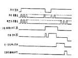
제5도는 상기 계수 및 반포장 장치에서 수행된 각 동작 공정을 예시한 타이망 챠트.5 is a tie chart illustrating each operation process performed in the counting and semi-packaging device.
* 도면의 주요부분에 대한 부호의 설명* Explanation of symbols for main parts of the drawings
1 : 스택판 2 : 지폐1: stack plate 2: banknote
2a : 지폐다발 3 : 안내 로울러2a: bundle of bills 3: guide roller
4 : 분리 드럼 5 : 반송판4: separation drum 5: carrier plate
6 : 지폐 감지 및 판별부 7 : L자형 반송 유지 부재6: bill detection and discrimination unit 7: L-shaped conveying holding member
8 : 배제 스택커 9 : 절환 셔터판8: exclusion stacker 9: switching shutter plate
10 : 스택 유니트 11 : 스택판10: stack unit 11: stack plate
12 : 수용판 13 : L자형 모서리 정렬판12: receiving plate 13: L-shaped corner alignment plate
14 : 반포장 유니트 15 : 프레임14: Half-packaging unit 15: Frame
16 : 슬라이더 17 : 반송 척16: Slider 17: Bounce Chuck
17a, 17b : 척부재 19 : 치차 택17a, 17b: Chuck member 19: Gear tag
20 : 반송 모터 23 : 브레이킹 유니트20: conveying motor 23: braking unit
25 : 반포장 링 25a : 시일링 테이프25: half-packed ring 25a: sealing tape
26 : 그립 솔레이노이드 27 : 정지판26: grip solenoid 27: stop plate
28 : 작동 봉28: working rod
본 발명은 지폐와 같은 종이 시이트들을 반-포장하거나 또는 밴드 실링(band-sealing)하고 기폐의 수를 계수하기 위한 장치에 관한 것이다.The present invention relates to an apparatus for semi-packing or band-sealing paper sheets, such as banknotes, and counting the number of bins.
종래에 사용되었던 이러한 종류의 지폐 계수기는 여러다른 액면가가 기재된 지폐들을 판별할 수 있는 기능이 전혀 부가되지 않아 소망의 액면가의 반 포장 다발 지폐 속에 다른 종류의 지폐가 섞여 고의가 아니게 지폐의 계산합이 틀리게 되는 경우가 종종 있었다.This type of bill counter used in the past does not have any function of discriminating banknotes with different face values, so that different types of bills are mixed into half-packed bundles of the desired face value, thus intentionally counting the bills. It was often wrong.
따라서, 이와같은 종래의 결점을 제거하기 위하여 지폐계수기에 지폐를 삽입하기 전에 지폐의 전 종별의 선별 작업을 행해야만 했었다. 그러나, 이러한 전 종별의 선별 작업을 사람이 수동으로 행하면 선별된 지폐중에 다른 종류의 지폐가 혼입하는 경우가 있어 돈의 합의 계산에 차질이 생겼었다. 더구나, 상술한 선별 작업에 있어서는 사람이 직접 손으로 선별하기 때문에 지페의 모서리가 구겨지면 한쪽으로 일렬로 정렬하기가 곤란하며 지페를 게수기에 삽입하면 모서리가 겹쳐진 지폐들도 계수 및 반포장 되기 때문에 반포장된 지폐들의 다발들을 일렬로 정렬하기가 곤란하였다.Therefore, in order to eliminate this conventional drawback, all sorts of bills had to be sorted before inserting bills into the bill counter. However, when a person performs manual sorting of all kinds, different types of bills may be mixed in the sorted bills, which causes a problem in calculating the sum of money. In addition, in the sorting operation described above, since the person sorts by hand, it is difficult to align the paper with one side when the edge of the paper is crumpled. It was difficult to line up bundles of semi-packaged bills.
본 발명의 목적은 상술한 종래 기술의 결점을 제거한 지폐의 계수 및 반포장 장치를 제공하는 데 있다. 본 발명에 따르면 지페의 액면가를 감지하거나 선별하기 위한 유니트와 지폐의 확실한 반송 상태가 송출 드럼에 의해 반출된 지페들의 반송 경로가 제공된다. 배재 지폐들은 배재 스택커에 수납되고 바람직한 소망의 지폐만이 반-포방용 스택 유니트에 수납되는 그러한 방법으로 상기 지페 판별 유니트를 통과한 지폐는 절환 셔터판에 의해 그들의 반송 방향이 변경된다.It is an object of the present invention to provide a counting and semi-packaging device for banknotes which eliminates the above-mentioned drawbacks of the prior art. According to the present invention, there is provided a conveying path of papers carried out by a delivery drum with a unit for detecting or sorting the face value of paper money and a sure conveyance state of paper money. Exclusion banknotes are stored in the exclusion stacker and only the desired desired banknotes are stored in the semi-cub stack unit, so that the banknotes passing through the paper discrimination unit are changed in their conveying direction by a switching shutter plate.
상기 언급한 "바람직한 소망의 지폐"란 의미는 수정된 장치를 가지는 장치내에서 사용되는 것으로 여기에 대응하는 액면가는 지폐 계수 및 반포장 장치에 의해 처리되는 액면가에 해당하는 것이다.The above-mentioned "preferred desired banknote" means that it is used in a device having a modified device, and the face value corresponding thereto corresponds to the face value processed by the banknote counting and semi-packaging device.
이하 첨부 도면에 의거 본 발명을 상세히 설명한다. 도면에서 예시 번호 1은 다수매의 적층된 지폐들(2)을 재치한 L자형의 스택판으로써, 이 스택판의 저면(1a)에는 한쌍의 안내 로울러(3)가 형성되어 있음과 동시에 이 지폐(2)를 송출하기 위한 분리 드럼(4)이 도시하지 않은 계수 모우터에 의하여 회전 자재하게 축지되고, 이 분리 드럼(4)의 축 중심으로부터 약 반경분의 부분은 상기 저판(1a)의 절결 요부(1b)내에 위치하고 있다.BEST MODE Hereinafter, the present invention will be described in detail with reference to the accompanying drawings. In the drawing, Example No. 1 is an L-shaped stack board in which a plurality of stacked bank notes 2 are placed. At the same time, a pair of guide rollers 3 are formed on the bottom face 1a of the stack board. Separation drum 4 for delivering (2) is rotatably held by a counting motor (not shown), and a portion of the radial portion from the center of the shaft of the separation drum 4 is cut out of the bottom plate 1a. It is located in the recessed part 1b.
상기 스택판(1)에 인접하는 하방 위치에는 반송로를 구성하는 반송판(5)이 형성됨과 동시에 이 반송판(5)의 상부, 즉 상기 스택판(1)에 인접한 하방 위치에는 지폐의 장변 길이와 단별길이, 패턴, 자기(magnetism), 지폐모서리의 겹쳐짐, 등의 검출을 행하며, 지폐의 종류를 판별하기 위한 지폐 감지 및 판별 유니트(6)가 형성되어 있다.The conveyance plate 5 which comprises a conveyance path is formed in the downward position adjacent to the said stack board 1, and the long side of a banknote is provided in the upper part of this conveyance board 5, ie, in the downward position adjacent to the said stack board 1, A bill detection and discrimination unit 6 for detecting the length and the section length, the pattern, the magnetism, the overlapping of the bill corners, and the like, for discriminating the types of bills is formed.
상기 지폐의 감지 및 판별 유니트(6)는 상기 전자기 수단에 의하여 구성되며, 신호 발생부(6a)와 신호 수신부(6b)가 전기 반송판(5)을 형지하여 대향 배치되어 있다. 상기 반송판(5)의 약 중앙부에 위치에는 도시하지 않은 본체에 지지된 L자형의 유지 부재(7)에 의하여 지지된 배제 스택커(8)가 배설되고, 이 배재 스택커(8)의 대향측에는 도시하지 않은 본 체에 회동 자재하게 축지되고, 도면에 있어 실선과 점선으로 나타낸 바와같은 2방향으로 회동하여 반송 방향을 변경할 수 있도록 구성된 절환 셔터판(9)이 배설되어 있다. 즉, 상기 절환 셔터판(9)이 2점 점선으로 나타내는 일방향으로 회동되어서 반송판(5)의 도시하지 않은 개구부를 거쳐서 상기 배제 스택커(8)측에 위치한 상태에서는 지폐(2)는 상기 배제 스택커(8)내에 송입되어서 수납되며, 상기 절환 셔터판(9)이 실선으로 나타내는 타방향으로 회동된 상태에서 지폐(2)는 직접 하방으로 송출된다.The banknote sensing and discriminating unit 6 is constituted by the electromagnetic means, and the signal generator 6a and the
또한, 상기 배제 스택커(8)에 인접한 반송판(5)의 하부 위치에는 스택커 유니트(10)를 구성하기 위한 스택판(11)과 수용판(12)이 배설되고, 이 스택판(11)과 수용판(12)에 인접한 위치에는 전체가 L자형태를 이루는 모서리 정렬판(13)이 배설되어 있다.In addition, a stack plate 11 and a receiving plate 12 for constituting the
상기 수용판(12)은 예시하지 않은 반-포장 장치의 본체에 회동 자재하게 축지되어 있음과 동시에 지폐들이 스택판(11)상에 고정되는 바와같이 제1도에서의 시계 방향으로 회전된다.The receiving plate 12 is rotated freely on the main body of the semi-packaging device, which is not illustrated and at the same time rotated clockwise in FIG. 1 as banknotes are fixed on the stacking plate 11.
상기 스택커 유니트(10)내의 일단에는 화살표 A의 방향으로 접동 자재하게 형성된 슬라이더(16)의 선단부에 장착된 반송 척(17)이 작동 자재하게 일렬로 배설되어 있다.At one end of the
상기 반송 척(17)은 한쌍의 개폐 자재하게 구성된 척 부재들(17a)(17b)로서 구성됨과 동시에 일반의 척부재(17a)에는 그 고정면이 철상이며, 타방의 부재(17b)는 그 척킹면이 요상을 이루고 있다.The conveying chuck 17 is configured as a pair of opening and closing
상기 슬라이더(16)는 요상 길이방향 형상을 이룬 슬라이드 가이드상에 접동 자재하게 형성되어 있음과 동시에 이 치차 랙(19)에는 반송 모우터(20)의 회전축(21)의 피니온(pinion)(22)과 치합하는 브레이킹 유니트(23)의 기어(24)와 치합하고 있으며, 이 랙부(19)를 통하여 상기 슬라이더(16)는 화살표 A의 방향으로 왕복 접동할 수 있는 구성이다. 상기 슬라이더(16)는 치차 랙(19)의 작동에 의해 화살표 A방향으로 왕복 운동한다.The slider 16 is slidably formed on the slide guide having a concave longitudinal shape, and at the same time, the gear rack 19 has a
또한 상기 슬라이더(16)의 선단부의 외주 위치에는 반-포장링(25)이 형성되고, 상기 슬라이더(16)의 후단부에는 그래핑 솔레노이드(26)를 갖는 고정판(27)이 장착되고, 이 솔레노이드(26)의 작동 봉(28)은 복귀 스프링(28a)을 통해 반송 척(17)에 연결된다. 예시번호 28a는 반송 척(17)을 개방하는 방향으로 작동봉을 정상적으로 바이어싱(biasing)하는 복귀스프링을 나타낸다.A
이하, 이상과 같은 구성의 본 발명의 액면가의 지폐를 선별하기 적당한 상술한 계수 및 반포장 장치에 관하여 기술한다.Hereinafter, the above-mentioned counting and half-packaging apparatus suitable for sorting the banknotes of the face value of the present invention having the above-described configuration will be described.
먼저, 스택판(1)상에 적층하여 유지된 지폐권의 종류가 다른 다수매의 지폐(2)는 도시하지 않은 계수 모우터에 의하여 회전되는 드럼(4)에 의하여 1매씩 지폐 판별 유니트(6)로 보내져 지폐의 종류를 판별한다.First, the bills discriminating unit 6, one by one, by the drum 4, which is rotated by a counting motor (not shown), which differs in the types of bills stacked and held on the stacking plate 1. ) To determine the type of bill.
상기 지폐 판별 유니트(6)에서 다른 종류의 지폐 또는 모서리가 겹쳐진 지폐 등의 배제 지폐로 판별된 경우에는 절환 셔터판(9)이 2점 점선으로 나타낸 일방향 위치에 회동된 상태로 되어 배제된 지폐가 배제 스택커(8)내에 송입되어서 수납되며, 상기 지폐 판별 유니트(6)에서 소망의 지폐의 종류의 소망의 지폐로 판별된 경우에는 절환 셔터 유니트(9)가 실선으로 나타낸 타방향 위치에 회동된 상태로 되며, 소망의 지폐가 스택커 유니트(10)의 스택판(11)상의 각 개방된 척부재(17a)과 척부재(17b)사이에 순차로 배열된다.When it is discriminated by the banknote discrimination unit 6 as exclusion banknotes, such as other kinds of banknotes or banknotes with overlapping corners, the switching shutter plate 9 is rotated to a one-way position indicated by a two-dot dotted line, and the banknotes excluded are excluded. It is fed and stored in the exclusion stacker 8, and when the banknote discrimination unit 6 discriminates the desired banknote of the desired banknote type, the switching shutter unit 9 is rotated to the other direction position indicated by the solid line. The desired bills are sequentially arranged between each open chuck member 17a and
이 스택커 유니트(10)내에 예를들면 100매의 소망의 지폐가 송입된 사실이 상기 지폐가 송입된 사실이 상기 지폐 판별 유니트(6)에 접속된 계수부(도시되지 않음)에 의하여 검출되면, 스택커판(12)이 도시하지 않은 구동 수단에 의하여 구동되어서 압축되며 또한 반송 모우터(20)가 역전하여 반송 척(17)에 의하여 지폐(2)가 정렬판(13)에 눌려서 정리되며 이 상태에서 그립 솔레노이드(26)가 작동하면 슬라이더(16)가 척킹에 필요한 거리분만큼 액 유니트(19)상에 접동하여 반송 척(17)의 각 척부재(17a)(17b)들이 화살표 B방향으로 페쇄된 상태로 되어서 지폐 다발(2a)의 일단을 척킹한다. 따라서 지폐 다발(2a)이 스택 유니트(10)로부터 이동함과 동시에 다음의 지페는 송입되어서 다음 계수가 개시된다.If the fact that 100 desired banknotes have been fed into the
다음에 전술한 척킹 상태에서 반송 모우터(20)가 정회전하면 피니온 기어(22)를 통하여 치차 랙부(19)와 슬라이더(16)로써 된 슬라이더(16)가 제1도에 있어 좌방향으로 이동되며, 지폐 다발(2a)이 척킹 상태대로 2점 점선으로 나타낸 위치, 즉 반-포장 링(25)내에 위치되며 브레이킹 유니트(23)에 의하여 정 위치에 슬라이더(16)가 정지함과 동시에 반-포장링(25)에 의하여 시일링 테이프(25a)가 지폐 다발(2a)이 외주부에 권회되어서 반 포장 동작이 완료한다.Next, when the conveying
반 포장이 완료되면 도시하지 않은 프린팅 솔레노이드가 작동하여 스탬프 시일에 의하여 날인되며, 반송 모우터(20)가 역회전하여 지폐 다발(2a)이 압출된다. 따라서 지폐 다발(2a)은 도시하지 않은 다발 스택커 속으로 유입되어 지지판(10a)에 의해 안내된다. 반송 척은 더 이동되어 상기 반송 전기 모우터의 동작이 완료할 때 종이 시이트의 새로운 다발을 그립하는 위치에 도달한다. 이상의 각 동작 공정에 있어서의 타이밍은 제5도의 타이밍 챠트에 나타낸 바와같다.When the semi-packing is completed, a printing solenoid (not shown) is operated to be stamped by a stamp seal, and the conveying
또한 제3도는 본 발명에 의한 지폐권의 판종 기능에 적합한 계수 및 반포장 장치의 반포장 유니트의 다른 실시예로서, 슬라이더(16)의 측벽에 치차 랙(19)이 형성되고, 이 슬라이더(16)의 고정판(27)에 형성된 그립 솔레노이드(26)의 작동 봉(28)은 척 부재(17a)(17b)에 형성되어 서로 치합하는 개폐기어(17c)와 개폐기어(17d)의 작동 레버(17e)와 연결되어 있으며, 상기 솔레노이드(26)의 작동에 의하여 제1도의 구성과 같이 지폐 다발(2a)의 척킹을 행할 수가 있다. 제3도에 있어서, 상기 슬라이더(16)가 실선으로 나타낸 위치에 있어서는 상기 반송 척(17)은 척킹 상태이며 2점 점선으로 나타낸 위치에 있어서는 지폐 다발(2a)을 척킹하여 반 포장 상태에 있음을 나타내 있다. 그리고 제3도에 있어서의 각 척부재(17a)와 척부재(17b)에 의하여 지폐 다발(2a)을 척킹한 상태는 제4도에 나타내 있으며, 지폐 다발(2a)이 곡절된 상태에서 확실히 척킹되어 있다.3 shows another embodiment of the counting and semi-packaging unit of the counting and semi-packaging device suitable for the sheet-making function of banknotes according to the present invention, wherein a gear rack 19 is formed on the side wall of the slider 16, and the slider 16 The actuating rod 28 of the grip solenoid 26 formed on the fixed plate 27 of the subassembly is formed on the
상술한 본 발명에 의한 지폐권 판정 기능을 가진 계수 및 반 포장기는 이상과 같은 구성과 작용을 갖고 있으므로 다른 금액의 지폐가 혼입할 경우 또는 모서리가 겹쳐진 지폐가 혼입할 경우에 있어서도 지폐 판별 유니트에 의하여 모두 판별되며 바람직한 지폐권만이 절환 셔터판에 의하여 스태커에 송입됨과 동시에 배제 지폐는 모두 절환 셔터 유니트에 의하여 배제 스택커에 송입되어 완전 자동 공정에 의하여 바람직한 지폐만이 반 포장된다.The counting and semi-wrapping machine having the banknote right determination function according to the present invention described above has the configuration and function as described above, so that even when bills of different amounts are mixed or bills with overlapping corners are mixed, the bill discrimination unit is used. All of them are discriminated and only the desired banknotes are sent to the stacker by the switching shutter plate, and at the same time, all of the excluded banknotes are sent to the rejection stacker by the switching shutter unit so that only the desired banknotes are half-wrap by the fully automatic process.
본 발명에 의하여 종래에 있어서의 서로 다른 종류의 지폐의 혼입과 겹쳐진 지폐의 반-포장을 완전히 방지할 수가 있다. 또 지폐 다발이 스택커를 벗어나면 곧 다음 계수가 개시할 수 있으모로 계수 개시로부터 반포장 완료까지의 택트 타임(tact time)을 단축할 수 있다.According to the present invention, it is possible to completely prevent the incorporation of different kinds of bills in the prior art and the semi-packaging of the overlapped bills. The next count may begin as soon as the bundle of banknotes leaves the stacker, thereby reducing the tact time from count start to half-packing completion.
Claims (3)
Translated fromKoreanApplications Claiming Priority (2)
| Application Number | Priority Date | Filing Date | Title |
|---|---|---|---|
| JP76487 | 1983-04-30 | ||
| JP58076487AJPS59201190A (en) | 1983-04-30 | 1983-04-30 | Counting band sealer with money type deciding function |
Publications (2)
| Publication Number | Publication Date |
|---|---|
| KR840009155A KR840009155A (en) | 1984-12-24 |
| KR890001803B1true KR890001803B1 (en) | 1989-05-23 |
Family
ID=13606567
Family Applications (1)
| Application Number | Title | Priority Date | Filing Date |
|---|---|---|---|
| KR1019840002318AExpiredKR890001803B1 (en) | 1983-04-30 | 1984-04-30 | Counting and semi-packaging device for bills with the ability to distinguish different face value bills |
Country Status (6)
| Country | Link |
|---|---|
| JP (1) | JPS59201190A (en) |
| KR (1) | KR890001803B1 (en) |
| CA (1) | CA1218969A (en) |
| DE (1) | DE3415783A1 (en) |
| FR (1) | FR2545011B1 (en) |
| GB (1) | GB2138789B (en) |
Families Citing this family (5)
| Publication number | Priority date | Publication date | Assignee | Title |
|---|---|---|---|---|
| US4727991A (en)* | 1985-11-01 | 1988-03-01 | Fleetwood Systems, Inc. | Scroll strip conveyor system |
| JP3727676B2 (en)* | 1994-09-27 | 2005-12-14 | 株式会社東芝 | Banknote handling equipment |
| IT1285719B1 (en)* | 1996-05-24 | 1998-06-18 | Gd Spa | DEVICE FOR THE TRAINING AND TRANSFER OF ORDERED STACKS OF SHEETS, IN PARTICULAR BANKNOTES |
| IT1306257B1 (en) | 1998-06-01 | 2001-06-04 | Gd Spa | DEVICE AND METHOD FOR THE FORMATION AND BANDING OF GROUPS SHEETS, IN PARTICULAR BANKNOTES. |
| JP2002137862A (en)* | 2000-11-06 | 2002-05-14 | Toshiba Corp | Bill processing device and bill processing method |
Family Cites Families (12)
| Publication number | Priority date | Publication date | Assignee | Title |
|---|---|---|---|---|
| GB820036A (en)* | 1900-01-01 | |||
| GB950653A (en)* | 1960-02-16 | 1964-02-26 | Simmons And Thompson Automatio | Improvements in or relating to apparatus for checking and sorting sheet material |
| JPS5317839U (en)* | 1976-07-21 | 1978-02-15 | ||
| US4179685A (en)* | 1976-11-08 | 1979-12-18 | Abbott Coin Counter Company, Inc. | Automatic currency identification system |
| US4111410A (en)* | 1977-03-31 | 1978-09-05 | Xerox Corporation | Sorting apparatus and reproducing machine |
| GB1558705A (en)* | 1977-07-11 | 1980-01-09 | Kolosov I A | Device for sorting aricles |
| GB2034286B (en)* | 1978-10-30 | 1983-01-19 | Tokyo Shibaura Electric Co | Thin sheet sorting apparatus |
| JPS55124886A (en)* | 1979-03-20 | 1980-09-26 | Laurel Bank Machine Co | Paper documents processing unit |
| JPS6222914Y2 (en)* | 1980-04-08 | 1987-06-11 | ||
| JPS56147258A (en)* | 1980-04-15 | 1981-11-16 | Laurel Bank Mach Co Ltd | Bank note deposition machine |
| JPS57121761A (en)* | 1981-01-22 | 1982-07-29 | Toshiba Corp | Automatic transaction device of currency |
| JPS58106675A (en)* | 1981-12-21 | 1983-06-25 | 武蔵株式会社 | Banknote sorting and counting machine |
- 1983
- 1983-04-30JPJP58076487Apatent/JPS59201190A/enactiveGranted
- 1984
- 1984-04-26CACA000452870Apatent/CA1218969A/ennot_activeExpired
- 1984-04-27DEDE19843415783patent/DE3415783A1/enactiveGranted
- 1984-04-27FRFR848406737Apatent/FR2545011B1/ennot_activeExpired
- 1984-04-30KRKR1019840002318Apatent/KR890001803B1/ennot_activeExpired
- 1984-04-30GBGB08411008Apatent/GB2138789B/ennot_activeExpired
Also Published As
| Publication number | Publication date |
|---|---|
| DE3415783A1 (en) | 1984-10-31 |
| GB2138789A (en) | 1984-10-31 |
| CA1218969A (en) | 1987-03-10 |
| DE3415783C2 (en) | 1987-12-10 |
| FR2545011B1 (en) | 1989-08-25 |
| GB8411008D0 (en) | 1984-06-06 |
| KR840009155A (en) | 1984-12-24 |
| JPS59201190A (en) | 1984-11-14 |
| GB2138789B (en) | 1986-12-31 |
| JPH0353676B2 (en) | 1991-08-15 |
| FR2545011A1 (en) | 1984-11-02 |
Similar Documents
| Publication | Publication Date | Title |
|---|---|---|
| US3976198A (en) | Method and apparatus for sorting currency | |
| US4483124A (en) | Sheet-like material processing apparatus | |
| TW417044B (en) | Paper money processing machine | |
| JP2507326B2 (en) | Aggregator with binding device | |
| US4570801A (en) | Document handling machine | |
| GB2056415A (en) | Sheet material sorting apparatus | |
| GB2225472A (en) | Coin removing apparatus for coin handling machine | |
| US8245830B2 (en) | Paper currency handling device | |
| EP0793201A2 (en) | Bill handling machine | |
| KR890001803B1 (en) | Counting and semi-packaging device for bills with the ability to distinguish different face value bills | |
| KR101320716B1 (en) | Device for taking out notes | |
| JPS6145278B2 (en) | ||
| US4993990A (en) | Unacceptable coin removing apparatus for coin handling machine | |
| KR101876503B1 (en) | Counter stop prevention structure for bill counting machines | |
| KR870001497B1 (en) | Paper sheet grip and transfer apparatus | |
| KR101884866B1 (en) | A Banknote Counter for Discriminating Denomination andfor Detecting Counterfeit Bill | |
| JP4281085B2 (en) | Banknote handling equipment | |
| JP3217530B2 (en) | Paper transport device | |
| JP4619739B2 (en) | Banknote handling machine | |
| KR0132199B1 (en) | Paper sheet processor | |
| JP2020009218A (en) | Paper sheet sealing mechanism and paper sheet processing apparatus | |
| JPH0319017Y2 (en) | ||
| JPS5842909B2 (en) | Paper sheet processing equipment | |
| JP3279858B2 (en) | Paper sorting machine | |
| JPH0115915B2 (en) |
Legal Events
| Date | Code | Title | Description |
|---|---|---|---|
| A201 | Request for examination | ||
| PA0109 | Patent application | St.27 status event code:A-0-1-A10-A12-nap-PA0109 | |
| PA0201 | Request for examination | St.27 status event code:A-1-2-D10-D11-exm-PA0201 | |
| R17-X000 | Change to representative recorded | St.27 status event code:A-3-3-R10-R17-oth-X000 | |
| PG1501 | Laying open of application | St.27 status event code:A-1-1-Q10-Q12-nap-PG1501 | |
| G160 | Decision to publish patent application | ||
| PG1605 | Publication of application before grant of patent | St.27 status event code:A-2-2-Q10-Q13-nap-PG1605 | |
| E701 | Decision to grant or registration of patent right | ||
| PE0701 | Decision of registration | St.27 status event code:A-1-2-D10-D22-exm-PE0701 | |
| GRNT | Written decision to grant | ||
| PR0701 | Registration of establishment | St.27 status event code:A-2-4-F10-F11-exm-PR0701 | |
| PR1002 | Payment of registration fee | St.27 status event code:A-2-2-U10-U11-oth-PR1002 Fee payment year number:1 | |
| PR1001 | Payment of annual fee | St.27 status event code:A-4-4-U10-U11-oth-PR1001 Fee payment year number:4 | |
| PR1001 | Payment of annual fee | St.27 status event code:A-4-4-U10-U11-oth-PR1001 Fee payment year number:5 | |
| PR1001 | Payment of annual fee | St.27 status event code:A-4-4-U10-U11-oth-PR1001 Fee payment year number:6 | |
| PR1001 | Payment of annual fee | St.27 status event code:A-4-4-U10-U11-oth-PR1001 Fee payment year number:7 | |
| PR1001 | Payment of annual fee | St.27 status event code:A-4-4-U10-U11-oth-PR1001 Fee payment year number:8 | |
| PR1001 | Payment of annual fee | St.27 status event code:A-4-4-U10-U11-oth-PR1001 Fee payment year number:9 | |
| PR1001 | Payment of annual fee | St.27 status event code:A-4-4-U10-U11-oth-PR1001 Fee payment year number:10 | |
| PR1001 | Payment of annual fee | St.27 status event code:A-4-4-U10-U11-oth-PR1001 Fee payment year number:11 | |
| FPAY | Annual fee payment | Payment date:20000404 Year of fee payment:12 | |
| PR1001 | Payment of annual fee | St.27 status event code:A-4-4-U10-U11-oth-PR1001 Fee payment year number:12 | |
| LAPS | Lapse due to unpaid annual fee | ||
| PC1903 | Unpaid annual fee | St.27 status event code:A-4-4-U10-U13-oth-PC1903 Not in force date:20010524 Payment event data comment text:Termination Category : DEFAULT_OF_REGISTRATION_FEE | |
| PC1903 | Unpaid annual fee | St.27 status event code:N-4-6-H10-H13-oth-PC1903 Ip right cessation event data comment text:Termination Category : DEFAULT_OF_REGISTRATION_FEE Not in force date:20010524 | |
| P22-X000 | Classification modified | St.27 status event code:A-4-4-P10-P22-nap-X000 | |
| P22-X000 | Classification modified | St.27 status event code:A-4-4-P10-P22-nap-X000 |