KR880001683B1 - Sujins Internal Combustion Engine - Google Patents
Sujins Internal Combustion EngineDownload PDFInfo
- Publication number
- KR880001683B1 KR880001683B1KR8204738AKR820004738AKR880001683B1KR 880001683 B1KR880001683 B1KR 880001683B1KR 8204738 AKR8204738 AKR 8204738AKR 820004738 AKR820004738 AKR 820004738AKR 880001683 B1KR880001683 B1KR 880001683B1
- Authority
- KR
- South Korea
- Prior art keywords
- water
- engine
- energy
- combustion chamber
- hydrogen
- Prior art date
- Legal status (The legal status is an assumption and is not a legal conclusion. Google has not performed a legal analysis and makes no representation as to the accuracy of the status listed.)
- Expired
Links
Images


Classifications
- F—MECHANICAL ENGINEERING; LIGHTING; HEATING; WEAPONS; BLASTING
- F02—COMBUSTION ENGINES; HOT-GAS OR COMBUSTION-PRODUCT ENGINE PLANTS
- F02C—GAS-TURBINE PLANTS; AIR INTAKES FOR JET-PROPULSION PLANTS; CONTROLLING FUEL SUPPLY IN AIR-BREATHING JET-PROPULSION PLANTS
- F02C3/00—Gas-turbine plants characterised by the use of combustion products as the working fluid
- F02C3/20—Gas-turbine plants characterised by the use of combustion products as the working fluid using a special fuel, oxidant, or dilution fluid to generate the combustion products
- F—MECHANICAL ENGINEERING; LIGHTING; HEATING; WEAPONS; BLASTING
- F01—MACHINES OR ENGINES IN GENERAL; ENGINE PLANTS IN GENERAL; STEAM ENGINES
- F01K—STEAM ENGINE PLANTS; STEAM ACCUMULATORS; ENGINE PLANTS NOT OTHERWISE PROVIDED FOR; ENGINES USING SPECIAL WORKING FLUIDS OR CYCLES
- F01K21/00—Steam engine plants not otherwise provided for
- F01K21/02—Steam engine plants not otherwise provided for with steam-generation in engine-cylinders
- F—MECHANICAL ENGINEERING; LIGHTING; HEATING; WEAPONS; BLASTING
- F01—MACHINES OR ENGINES IN GENERAL; ENGINE PLANTS IN GENERAL; STEAM ENGINES
- F01K—STEAM ENGINE PLANTS; STEAM ACCUMULATORS; ENGINE PLANTS NOT OTHERWISE PROVIDED FOR; ENGINES USING SPECIAL WORKING FLUIDS OR CYCLES
- F01K21/00—Steam engine plants not otherwise provided for
- F01K21/04—Steam engine plants not otherwise provided for using mixtures of steam and gas; Plants generating or heating steam by bringing water or steam into direct contact with hot gas
- F—MECHANICAL ENGINEERING; LIGHTING; HEATING; WEAPONS; BLASTING
- F02—COMBUSTION ENGINES; HOT-GAS OR COMBUSTION-PRODUCT ENGINE PLANTS
- F02B—INTERNAL-COMBUSTION PISTON ENGINES; COMBUSTION ENGINES IN GENERAL
- F02B43/00—Engines characterised by operating on gaseous fuels; Plants including such engines
- F02B43/10—Engines or plants characterised by use of other specific gases, e.g. acetylene, oxyhydrogen
- F—MECHANICAL ENGINEERING; LIGHTING; HEATING; WEAPONS; BLASTING
- F02—COMBUSTION ENGINES; HOT-GAS OR COMBUSTION-PRODUCT ENGINE PLANTS
- F02B—INTERNAL-COMBUSTION PISTON ENGINES; COMBUSTION ENGINES IN GENERAL
- F02B47/00—Methods of operating engines involving adding non-fuel substances or anti-knock agents to combustion air, fuel, or fuel-air mixtures of engines
- F02B47/02—Methods of operating engines involving adding non-fuel substances or anti-knock agents to combustion air, fuel, or fuel-air mixtures of engines the substances being water or steam
- F—MECHANICAL ENGINEERING; LIGHTING; HEATING; WEAPONS; BLASTING
- F02—COMBUSTION ENGINES; HOT-GAS OR COMBUSTION-PRODUCT ENGINE PLANTS
- F02C—GAS-TURBINE PLANTS; AIR INTAKES FOR JET-PROPULSION PLANTS; CONTROLLING FUEL SUPPLY IN AIR-BREATHING JET-PROPULSION PLANTS
- F02C3/00—Gas-turbine plants characterised by the use of combustion products as the working fluid
- F02C3/20—Gas-turbine plants characterised by the use of combustion products as the working fluid using a special fuel, oxidant, or dilution fluid to generate the combustion products
- F02C3/30—Adding water, steam or other fluids for influencing combustion, e.g. to obtain cleaner exhaust gases
- F—MECHANICAL ENGINEERING; LIGHTING; HEATING; WEAPONS; BLASTING
- F02—COMBUSTION ENGINES; HOT-GAS OR COMBUSTION-PRODUCT ENGINE PLANTS
- F02B—INTERNAL-COMBUSTION PISTON ENGINES; COMBUSTION ENGINES IN GENERAL
- F02B1/00—Engines characterised by fuel-air mixture compression
- F02B1/02—Engines characterised by fuel-air mixture compression with positive ignition
- F02B1/04—Engines characterised by fuel-air mixture compression with positive ignition with fuel-air mixture admission into cylinder
- Y—GENERAL TAGGING OF NEW TECHNOLOGICAL DEVELOPMENTS; GENERAL TAGGING OF CROSS-SECTIONAL TECHNOLOGIES SPANNING OVER SEVERAL SECTIONS OF THE IPC; TECHNICAL SUBJECTS COVERED BY FORMER USPC CROSS-REFERENCE ART COLLECTIONS [XRACs] AND DIGESTS
- Y02—TECHNOLOGIES OR APPLICATIONS FOR MITIGATION OR ADAPTATION AGAINST CLIMATE CHANGE
- Y02T—CLIMATE CHANGE MITIGATION TECHNOLOGIES RELATED TO TRANSPORTATION
- Y02T10/00—Road transport of goods or passengers
- Y02T10/10—Internal combustion engine [ICE] based vehicles
- Y02T10/12—Improving ICE efficiencies
- Y—GENERAL TAGGING OF NEW TECHNOLOGICAL DEVELOPMENTS; GENERAL TAGGING OF CROSS-SECTIONAL TECHNOLOGIES SPANNING OVER SEVERAL SECTIONS OF THE IPC; TECHNICAL SUBJECTS COVERED BY FORMER USPC CROSS-REFERENCE ART COLLECTIONS [XRACs] AND DIGESTS
- Y02—TECHNOLOGIES OR APPLICATIONS FOR MITIGATION OR ADAPTATION AGAINST CLIMATE CHANGE
- Y02T—CLIMATE CHANGE MITIGATION TECHNOLOGIES RELATED TO TRANSPORTATION
- Y02T10/00—Road transport of goods or passengers
- Y02T10/10—Internal combustion engine [ICE] based vehicles
- Y02T10/30—Use of alternative fuels, e.g. biofuels
Landscapes
- Engineering & Computer Science (AREA)
- Chemical & Material Sciences (AREA)
- Combustion & Propulsion (AREA)
- Mechanical Engineering (AREA)
- General Engineering & Computer Science (AREA)
- Engine Equipment That Uses Special Cycles (AREA)
- Output Control And Ontrol Of Special Type Engine (AREA)
- Fuel-Injection Apparatus (AREA)
Abstract
Description
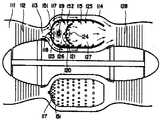
Translated fromKorean제1도는 본 발명의 수소개스 엔진을 피스톤형 왕복엔진에 적용한 경우의 실린더 단면도.1 is a cross-sectional view of a cylinder when the hydrostatic engine of the present invention is applied to a piston-type reciprocating engine.
제2도는 제1도에 도시한 수소개스 엔진의 연료공급 계통도.FIG. 2 is a fuel supply system diagram of the water injection engine shown in FIG. 1. FIG.
제3도는 본 발명의 수소개스 엔진을 로우터리엔진에 적용한 경우의 연료공급 계통도.3 is a fuel supply system diagram when the water injection engine of the present invention is applied to a rotary engine.
* 도면의 주요부분에 대한 부호의 설명* Explanation of symbols for main parts of the drawings
1 : 실린더 3 : 점화플러그1
4 : 흡기밸브 5 : 배기밸브4: intake valve 5: exhaust valve
6 : 수소개스가압분사노즐 7 : 분무수분사노즐6: water injection pressurizing nozzle 7: spray water spray nozzle
8 : 수소개스 9 : 흡기구8: Introduction 9: Intake vent
10 : 연소실 11 : 흡기구10
12 : 피스톤 13 : 수소개스용기12: piston 13: water introduction container
14 : 수소개스공급로 15,20 : 압력조정기14:
16. 19 : 체크밸브 17 : 조절기16. 19: check valve 17: regulator
18 : 저압개스공급용우회로 23 : 기화기18: low pressure gas supply bypass 23: vaporizer
24 : 진공파이프 25 : 물탱크24: vacuum pipe 25: water tank
28 : 분무펌프 61 : 수소개스분사노즐28: spray pump 61: water injection nozzle
70 : 로우터하우징70: rotor housing
본 발명은 수소개스엔진에 관한것이다.The present invention relates to a water introduction engine.
주지하고 있는 바와같이 수소개스엔진은 석유계 연료엔진에 비교하여, 연료비의 경제성과 무공해로해서 이점을 갖고 있기 때문에 이미 각분야에서 시작연구가 되고있다.As is well known, Sujins Engine has already been started in each field because it has advantages in terms of fuel economy and pollution-free compared to petroleum-based fuel engines.
그러나 지금까지 시험제작된 대부분의 수소개스엔진은 출력, 엔진형성과 중량 및 경제성등의 면에서 종래의 석유계 연료를 사용하는 엔진에 비교하여 실용성이 대9 뒤떨어지고, 따라서 개발도 답보상태에 머무르고 있는 것이 현상태이다.However, most of the pilot engines that have been tested so far are far less practical than conventional petroleum fuel engines in terms of power, engine formation, weight, and economy, and thus remain undeveloped. It is present condition.
종래에 있어서 시험제작된 수소엔진이 아직까지 실용단계에 도달하지 못한 근본적인 원인은 그 모든 시도가 수소개스의 연소폭발에너지를 종래의 석유연료의 연소 폭발에너지와 똑같이 그대로 기계적운동에너지로 전환시키도록 시도하고 있다는데 있다.The root cause of the conventionally tested hydrogen engines not yet reaching the practical level is that all attempts have been made to convert Suzhou's combustion explosive energy into mechanical kinetic energy just as it does for conventional petroleum fuels. I'm doing it.
수소개스를 기계적운동에너지를 얻기 위한 연료로서 고찰한 경우, 수소개스는 그의 연소속도가 석요계연료의 그것과 비교해서 현저히 급속하고, 그 결과 얻어지는 연소폭발에너지의 기계적운동에너지로의 전환율이 현저히 낮기 때문에, 기계적 운동에너지로 전환되지않는 잔여열에너지가 연소실내에 잔존하여 축적됨으로서, 연소실 형성부분 및 그주변 기기의 비정상적인 온도 상승을 초래하고, 수소개스의 연소실내로의 원활한 공급과 요구착화 시기등이 불확실하게 되어, 적절한 엔진구동이 이루어지지 않는다.In the case of considering the hydrophobic gas as a fuel for obtaining mechanical kinetic energy, the hydrophobic gas has a significantly rapid combustion rate compared with that of the stone-based fuel, and the conversion rate of the resulting combustion explosion energy into mechanical kinetic energy is significantly lower. Therefore, residual heat energy, which is not converted into mechanical kinetic energy, remains and accumulates in the combustion chamber, resulting in abnormal temperature rise of the combustion chamber forming portion and the surrounding equipment, and it is uncertain about the time of smooth supply and required ignition of the combustion gas into the combustion chamber. As a result, proper engine drive is not achieved.
종래에 있어서도 수소개스를 연소시킨 경우의 고부하시에 있어서, 역화나 노킹의 발생 및 과열부분의 온도강화를 목적으로하여 수소개스와 함께 물을 흡입시키는 방법은 제창되었다.In the prior art, a method of inhaling water together with a water injector for the purpose of backfire, knocking and temperature increase of an overheated portion has been proposed at high loads when the water injector is burned.
그러나 종래에 있어서 이러한 종류의 시도는 어느것이든 수소와 물을 공기를 미리혼합한 상태로 연소실에 보내는 것이기때문에 역화나 노킹의 방지는 어느 정도 가능하여도, 최대출력시에는 충분히 효과를 얻을 수 없다는 문제점을 갖고 있었다.However, in the conventional art, since this kind of attempt is to send hydrogen and water to the combustion chamber with air mixed in advance in advance, even if the prevention of backfire or knocking is possible to some extent, the effect cannot be sufficiently obtained at the maximum output. Had.
본 발명은 상기와 같이, 종래에 있어서 수소개스엔진의 문제점을 해소하고, 수소개스의 연소폭발에너지의 기계적운동에너지로의 전환율을 높일수 있는 실용화가 가능한 수소개스엔진의 제공을 목적으로 한 것이다.As described above, the present invention aims to provide a water injection engine which can be practically used to solve the problems of the water injection engine in the related art and to increase the conversion rate of the combustion explosion energy into the mechanical kinetic energy.
본 발명에 속하는 수소개스엔진은 수소개스를 연소시내에서 착화연소시킴에 의하여 발생되는 열에너지를 기계적운동에너지로서 이용함은 물론, 연소실내에 상기 수소개스와는 별도로 물을 수소개스와 미리혼합한 상태는 아니고 분무수의 상태로 직접분사공급함에 의해서, 상기한 수소개스의 연소열에너지를 이용해서 이 분무수를 증기에너지로 전환시키고, 상기 수소개스의 연소폭발 에너지와 증기에너지와의 병합작용에 의하여, 동력원으로서의 기계적운동 에너지에로의 전환율이 높게되도록 함과 아울러 이방식에 따라서 얻어지는 구동력이 고부하의 상태는 물론 저부하의 상태에 있어서도 지장없이 원활할수 있도록 한것을 특징으로 하는 것이다.The hydrophobic engine belonging to the present invention utilizes thermal energy generated by ignition combustion in the combustion city as a mechanical kinetic energy, as well as a state in which water is mixed in advance in the combustion chamber separately from the hydrophobic gas. Instead, the sprayed water is converted into steam energy by directly supplying the sprayed water in the state of the sprayed water, and the combined power of the combustion explosive energy and the steamed energy of the sprayed water is a power source. It is characterized in that the conversion to mechanical kinetic energy is increased and the driving force obtained according to this method can be smoothly performed even in a high load state as well as a low load state.
다음에 본발명에 속하는 수소엔진을 도시한 실시예에 따라서 상세히 설명하면, 제1도는 본발명을 왕복엔진에 적용한 경우의 실린더 단면도이다.Next, a hydrogen engine pertaining to the present invention will be described in detail with reference to the illustrated embodiment. FIG. 1 is a cross-sectional view of a cylinder when the present invention is applied to a reciprocating engine.
도시한 바와 같이 실린더 (1)에 있어서 실린더헤드 (2)에는 점화플러그(3), 흡기밸브(4) 및 배기밸브(5)와 함께, 수소개스가압분사노즐(6)과 분무수분사노즐(7)을 각각 수소개스(8) 및 분무수(9)가 연소실 (10)내에 분출되도록 병설한다. 일들 수소개스 가압분사노즐(6)및 분무수 분사노즐(7)은 어느것이든 도시한외의 공급장치로부터 수소개스(8)및 분무수(9)를 동시에, 또는 타이밍을 약간 늦춘 상태에서 연소실(10)내에 분사한다.As shown in the drawing, in the cylinder 1, the cylinder head 2, together with the
수소개스(8) 및 분무수(9)의 분사는 통상의 석유계 연료에 의한 엔진과 같이 흡기밸브(4)와 9 배개밸브(5)가 함께 폐쇄된 상태에서 피스톤(12)이 상승하는 압축행정에서 행하여지고, 피스톤(12)이 상승하는 압축행정에서 행하여지고, 피스톤(12)이 상사점에 도달하기 직전에 각각의 분사가 정지되고, 동시에 점화플러그(3)에 의하여 압축된 수소개스에 점착화 된다.The injection of the water injection 8 and the sprayed water 9 is a compression in which the
수소개스의 착화연소에 의한 열에너지는 직접 기계적운동에너지로 전환됨과 동시에 그일부가 연소실(10)내의 분무수를 순간적으로 증기에너지로 변화시키고, 수소개스의 폭발열에너지와 증기에너지가 병합해서 피스톤(12)을 압축하여 기계적운동에너지로 전환된다.The heat energy by ignition combustion of SuoShux is directly converted into mechanical kinetic energy, and at the same time, a part of the sprayed water in the
상기 폭발행정에 연이어서 행하여지는 배기 및 흡기의 각 행정은 통상의 석유계연료엔진과 같다.Each stroke of the exhaust and the intake air which is performed following the explosion stroke is the same as a conventional petroleum fuel engine.
제2도는 본 수소개스엔진의 연료공급로를 표시하는 계통도로서, 수소개스(8)는 용기(13)로 부터 개스공급로(14)를 통하여 기화기(23)를 통하지 않고 실린더(1)내에 직접 가압분사된다.2 is a system diagram showing the fuel supply path of the water injection engine, wherein the water injection 8 is directly from the
이 공급로(14)는 용기 (13)의 입구에 설치한 압력조정기 (15)에 의하여 수소개스를 약5㎏f/㎤정도의 압력으로 공급하지만, 도중에 체크밸브(16)와 감압및 유량조정을 행 하는 조절기(17)를 갖고있어서 수소개스는 조절기(17)를 통하여 0.5㎏f/㎤ 정도의 저압으로 가압분사노즐 (6)에 보내어지고, 이 노즐(6)에 의하여 소정의 압력으로 실린더 (1)내에 가압분사된다.The
또 상기 개스공급로(14)에 있어서 체크밸브(16)가 설치되어 있는 부분의 양측에는 저부하용의 저압개스공급용우회로(18)가 설치되어 있다.In addition, low pressure
이 우회로(18)는 체크밸브(19)와 압력조정기(20)를 갖고 있고, 이 압력조정 기(20)에 의하여 용기(13)로부터 약 5㎏f/㎤ 정도로 보내어지는 개스를 0.1㎏f/㎤ 정도로 감압하도록 되어있다.This
이 우회로(18)는 완속운전과 같이 저부하상태의 경우, 예를들면 가속패달(21)에 설치된 리미트 스위치(22)가 후퇴한 페달(21)에 의하여 폐쇄됨으로, 이 우회로(18)으 체크밸브(19)를 열고, 동시에 공급로 (14)의 체크밸브(16)가 폐쇄되어 상기와 같이 0.1㎏f/㎤ 정도로 감압된 저압개스가 조절기(17)내에 보내어진다.The
그런데, 이 조절기(17)의 설정압력은 우회로(18)로부터 유입되는 개스압력보다 크기 때문에, 우회로(18)로부터의 저압개스는 0.1㎏f/㎤ 정도의 저압 그대로 가압 분사노즐(6)에 보내어지고, 이 노즐(6)에 의하여 소정의 압력으로 가압된 상태에서 실린더(1)내에 분사된다.By the way, since the set pressure of this
기압페달(21)을 밟아서 고부하 상태로 되면 상기 스위치(22)가 열리고. 우회로(18)의 체크밸브(19)닫히며, 동시에 공급로(14)의 체크밸브(16)가 열려서 용기(13)로부터의 개스조절기(17)에 보내어지고. 이 조절기(17)에 의하여 이루어 진 0.5㎏f/㎤ 정도의 압력으로 가압분사노즐 (6)에 보내어지며, 이 노즐 (6)에 의하여 소정압력으로 가압된 실린더(1)내에 분사된다.When stepping on the air pressure pedal (21) to the high load state, the
엔진 회전수의 변화에 따르는 수소개스(8)의 공급량의 증감은 기화기(23)의 드로틀 밸브의 개폐정도에 의하여 기화기(23)와 상기 조절기(17)를 연결하는 진공파이프(24)를 통하여 행하여지는 조절기(17)의 유량조정에 의하여 가능하다.The increase and decrease of the supply amount of the water injection 8 according to the change of the engine speed is performed through the
수소개스(8)와 함께 실린더(1)내에 분사된 분무수(9)는, 물탱크(25)로부터 급수펌프(26)를 갖는 관(27)에 의하여 보내어지는 물을 엔진회전수에 대응해서 제어된 분사펌프 (28)에 의하여, 회전수의 변화에 대응된 공급량이 조정되도록 해서 안개모양으로 분사되도록 함으로써 얻어진다.The sprayed water 9 injected into the cylinder 1 together with the water injection 8 causes the water sent from the
제3도는 본 발명을 로우터리엔진에 적용한 경우의 연료공급로 계통도이다.3 is a schematic diagram of a fuel supply path when the present invention is applied to a rotary engine.
이 경우에 있어서는, 수소개스(8)의 공급계통은 상기의 왕복엔지의 경우와 같지만, 분무수(9)의 공급계통이 약간 왕복엔진의 경우와 다르다.In this case, although the supply system of the water injection 8 is the same as that of the reciprocating engine mentioned above, the supply system of the sprayed water 9 is slightly different from the case of the reciprocating engine.
이 로우터리엔진의 경우에는, 분무수용의 물은 탱크(25)로부터 급수펌프 (26)에 의하여 기화기 (23)에 보내어지고, 이 기화기(23)에 의하여 안개상태로 변화되어 공기와 함께 흡기구(11)를 통해서 로우터하우징(70)내에 분사된다.In the case of this rotary engine, water for spraying water is sent from the
한편 수소개스(8)는 조절기(17)로부터 흡기구(11)외 일부에 설치된 노즐 (61)로부터 분무수(9)와의 흡기구(11)에의 분사는 별도로 행하여진다는 의미에서, 수소개스와 물과 공기를 미리 혼합한 실린더내에 공급하는 종래로 부터 알려진 예비 혼합방식과는 기본적으로 다르다.On the other hand, the water injection 8 is sprayed from the
본 발명에 속하는 수소개스엔진에 있어서는, 수소개스 자체의 연소 속도는 빠르지만, 이 연소에 의해서 초래되는 분무수의 중기화 속도가 석유계연료의 연소 속도에 비해서 느리기때문에, 수소개스의 폭발연소와 분무소의 중기화가동인연소실내에서 일련의 연관을 가진 상태로 행하여지는 결과, 기계적운동에너지로의 전환을 석유계연료의 연소에 의한 기계적운동에너지로의 전환과 근사한 상태로 할수있다.In the hydrous engine belonging to the present invention, although the combustion rate of the hydrogel itself is fast, since the neutralization rate of the sprayed water caused by this combustion is slower than the combustion rate of petroleum fuel, As a result of a series of associations in the combustion chamber of the atomization operation of the atomizing station, the conversion to mechanical kinetic energy can be approximated to the conversion to mechanical kinetic energy by combustion of petroleum fuel.
그 결과 본 발명에 속하는 수소개스엔진에 있어서는 수소개스만을 연소시킨 경우에 기계적운동 에너지로서 유효하게 전환할수는 없고 다만 배출된 수소개스의 열에너지를 손실함이 없이 효율적으로 잘 이용할수 있고, 그부분의 기계적 운동에너지를 증대시킬수가 있다.As a result, in the hydrophobic engine belonging to the present invention, when only the hydrophobic gas is burned, it cannot be effectively converted into mechanical kinetic energy, but it can be effectively used efficiently without losing the thermal energy of the discharged hydrophobic gas. It can increase the mechanical kinetic energy.
또 이 엔진에 있어서는, 수소개스와 함께 연소실내에 공급되는 물을, 수소개스와 미리 혼합되어있지 않는 분무수 상태로 직접공급하는 것으로서, 이 분무수의 공급에 의하여 연소실내에서 증기에너지의 발생을 가능하게 할수있으며, 이 증기에너지의 발생이 수소개스연소에 따르는 기계적운동에너지로의 전환율을 향상시키는 역활을 한다.In this engine, the water supplied to the combustion chamber together with the water vapor is directly supplied in the form of spray water which is not mixed with the water vapor in advance, and the supply of the spray water prevents the generation of steam energy in the combustion chamber. It is possible to do this, and the generation of this steam energy serves to improve the conversion rate into mechanical kinetic energy following combustion.
그리고, 이 분무수의 공급에 의하여 수소개스의 연소에 따르는 잔여 열에너지가 감소하기 때문에 연소실 형성 부분과 함께 연소실 주변기기부의 온도상승을 억제할수가 있고, 따라서, 수소개스의 연소실내로의 원활한 공급과 요구된 착화시기가 가능하게되는 이점을 갖고 있다.In addition, since the residual heat energy caused by the combustion of water is reduced by the supply of the sprayed water, it is possible to suppress the temperature rise of the peripheral part of the combustion chamber together with the combustion chamber forming portion. The ignition time has the advantage that it becomes possible.
또 본 발명의 수소개스 엔진에서는, 수소개스 공급로(14)에 저부하시의 운전에 적합한 설정압력 이하의 저압 수소개스를 공급할수있는 저압개스공급용 우회로(18)를 구비하고 있기때문에 상기 공급로(14)를 통해서의 고부하시의 운전을 원활히 행하는 것은 물론, 완속운전과 같은 저부하시의 운전도 이 우회로(18)를 통해서의 저압개스의 공급에 의하여 지장없이 원활하게 지속할 수가 있다.Further, in the water injection engine of the present invention, since the low pressure
실험에 의하면, 시판이 1800CC 왕복엔진차 및 로우터리엔진차의 엔진을 그대로 이용해서 본발명을 적용한 결과, 저속주행은 물론, 120㎞ 까지의 고속중도 지장없이 행하는 것이 가능하였다.According to the experiment, as a result of applying the present invention using commercially available engines of a 1800CC reciprocating engine and a rotary engine car, it was possible to perform low speed driving and high speed up to 120 km without interruption.
따라서, 본 발명에 의하면, 수소개스의 연소폭발에너지를 증기에너지와의 병합에 의하여 효율이 양호한 기계적운동에너지로의 전환 이용이 가능하여서, 종래부터 실용화가 문제로된 새로운 동력원으로서의 수소개스엔진을 확실히 실용화 할 수 있는 효과를 갖는 것이다.Therefore, according to the present invention, it is possible to use the conversion of the combustion explosive energy of the hydrofoil into mechanical kinetic energy with good efficiency by merging with the steam energy, thereby ensuring the hydrophobic engine as a new power source which has conventionally been a practical problem. It has the effect that can be put to practical use.
Claims (1)
Translated fromKoreanPriority Applications (1)
| Application Number | Priority Date | Filing Date | Title |
|---|---|---|---|
| KR1019880004679AKR880001431B1 (en) | 1981-11-12 | 1988-04-23 | Hydrogen gas tubine engine |
Applications Claiming Priority (4)
| Application Number | Priority Date | Filing Date | Title |
|---|---|---|---|
| JP56180409AJPS5882005A (en) | 1981-11-12 | 1981-11-12 | Hydrogen gas engine |
| JP56-180409 | 1981-11-12 | ||
| JP57014819AJPS58133449A (en) | 1982-02-03 | 1982-02-03 | Hydrogen gas engine |
| JP57-14819 | 1982-02-03 |
Related Child Applications (1)
| Application Number | Title | Priority Date | Filing Date |
|---|---|---|---|
| KR1019880004679ADivisionKR880001431B1 (en) | 1981-11-12 | 1988-04-23 | Hydrogen gas tubine engine |
Publications (2)
| Publication Number | Publication Date |
|---|---|
| KR840002070A KR840002070A (en) | 1984-06-11 |
| KR880001683B1true KR880001683B1 (en) | 1988-09-06 |
Family
ID=11871645
Family Applications (1)
| Application Number | Title | Priority Date | Filing Date |
|---|---|---|---|
| KR8204738AExpiredKR880001683B1 (en) | 1981-11-12 | 1982-10-22 | Sujins Internal Combustion Engine |
Country Status (2)
| Country | Link |
|---|---|
| JP (1) | JPS58133449A (en) |
| KR (1) | KR880001683B1 (en) |
Families Citing this family (5)
| Publication number | Priority date | Publication date | Assignee | Title |
|---|---|---|---|---|
| JPH0799122B2 (en)* | 1986-11-13 | 1995-10-25 | ヤマハ発動機株式会社 | Output control device for gas fuel engine |
| AU4362297A (en)* | 1996-06-21 | 1998-01-07 | World Fusion Limited | Internal combustion engine using water decomposition gas |
| GR1004226B (en)* | 2002-02-05 | 2003-05-05 | Γεωργιος Ιωαννου Πολυζωης | Environmentally friendly internal combustion engine. |
| GB0426933D0 (en)* | 2004-12-08 | 2005-01-12 | Phillips Malcolm | An engine which operates on water |
| US7739985B2 (en) | 2006-03-23 | 2010-06-22 | Lonox Engine Company, Inc. | Internal combustion water injection engine |
- 1982
- 1982-02-03JPJP57014819Apatent/JPS58133449A/enactiveGranted
- 1982-10-22KRKR8204738Apatent/KR880001683B1/ennot_activeExpired
Also Published As
| Publication number | Publication date |
|---|---|
| JPS6217646B2 (en) | 1987-04-18 |
| KR840002070A (en) | 1984-06-11 |
| JPS58133449A (en) | 1983-08-09 |
Similar Documents
| Publication | Publication Date | Title |
|---|---|---|
| EP0079736B1 (en) | Internal combustion engine for hydrogen gas | |
| US5718194A (en) | In-cylinder water injection engine | |
| US4446830A (en) | Method of operating an engine with a high heat of vaporization fuel | |
| US10858990B2 (en) | Internal combustion steam engine | |
| CN109469564B (en) | Internal combustion engine using water-based mixture as fuel and method of operating the same | |
| CN101368527B (en) | Hydrogen gas fuel internal combustion engine, its hydrogen gas injection system and combustion method | |
| EP2690280B1 (en) | Injection device | |
| EP1053395B1 (en) | A combined diesel-rankine cycle reciprocating engine | |
| US6449940B2 (en) | Internal combustion engine | |
| KR0165563B1 (en) | Piston type internal combustion engine | |
| US1653825A (en) | Internal-combustion engine | |
| US2692587A (en) | Internal-combustion engine | |
| KR880001683B1 (en) | Sujins Internal Combustion Engine | |
| US2376479A (en) | Internal-combustion engine and combustion mixture therefor | |
| JPH08261004A (en) | Spray water injection type stroke separation engine | |
| US2646026A (en) | Thermal motor with injection cylinder | |
| US2005063A (en) | Method of operating internal combustion engines | |
| US1928754A (en) | Method of and apparatus for preparing and using fuel in internal combustion engines | |
| SU767380A1 (en) | Gas diesel four-stroke internal combustion engine | |
| BE1009721A6 (en) | Thermal compensation engines | |
| JPH08135515A (en) | Engine | |
| US1821817A (en) | Method of injection of fuel for internal combustion engines | |
| US961581A (en) | Explosive-engine. | |
| CN116291852A (en) | Engine rotational flow type precombustor with lateral layout | |
| JPS63219831A (en) | Fuel controller for diesel engine |
Legal Events
| Date | Code | Title | Description |
|---|---|---|---|
| PA0109 | Patent application | St.27 status event code:A-0-1-A10-A12-nap-PA0109 | |
| R17-X000 | Change to representative recorded | St.27 status event code:A-3-3-R10-R17-oth-X000 | |
| P11-X000 | Amendment of application requested | St.27 status event code:A-2-2-P10-P11-nap-X000 | |
| P13-X000 | Application amended | St.27 status event code:A-2-2-P10-P13-nap-X000 | |
| P11-X000 | Amendment of application requested | St.27 status event code:A-2-2-P10-P11-nap-X000 | |
| P13-X000 | Application amended | St.27 status event code:A-2-2-P10-P13-nap-X000 | |
| PG1501 | Laying open of application | St.27 status event code:A-1-1-Q10-Q12-nap-PG1501 | |
| PA0201 | Request for examination | St.27 status event code:A-1-2-D10-D11-exm-PA0201 | |
| PE0902 | Notice of grounds for rejection | St.27 status event code:A-1-2-D10-D21-exm-PE0902 | |
| P11-X000 | Amendment of application requested | St.27 status event code:A-2-2-P10-P11-nap-X000 | |
| P13-X000 | Application amended | St.27 status event code:A-2-2-P10-P13-nap-X000 | |
| PG1605 | Publication of application before grant of patent | St.27 status event code:A-2-2-Q10-Q13-nap-PG1605 | |
| PE0701 | Decision of registration | St.27 status event code:A-1-2-D10-D22-exm-PE0701 | |
| PR0701 | Registration of establishment | St.27 status event code:A-2-4-F10-F11-exm-PR0701 | |
| PR1002 | Payment of registration fee | St.27 status event code:A-2-2-U10-U11-oth-PR1002 Fee payment year number:1 | |
| PR1001 | Payment of annual fee | St.27 status event code:A-4-4-U10-U11-oth-PR1001 Fee payment year number:4 | |
| PR1001 | Payment of annual fee | St.27 status event code:A-4-4-U10-U11-oth-PR1001 Fee payment year number:5 | |
| PR1001 | Payment of annual fee | St.27 status event code:A-4-4-U10-U11-oth-PR1001 Fee payment year number:6 | |
| PC1903 | Unpaid annual fee | St.27 status event code:A-4-4-U10-U13-oth-PC1903 Not in force date:19940907 Payment event data comment text:Termination Category : DEFAULT_OF_REGISTRATION_FEE | |
| PC1903 | Unpaid annual fee | St.27 status event code:N-4-6-H10-H13-oth-PC1903 Ip right cessation event data comment text:Termination Category : DEFAULT_OF_REGISTRATION_FEE Not in force date:19940907 |