KR870001196B1 - Dispensing pump adapted for pressure filling - Google Patents
Dispensing pump adapted for pressure fillingDownload PDFInfo
- Publication number
- KR870001196B1 KR870001196B1KR1019840003226AKR840003226AKR870001196B1KR 870001196 B1KR870001196 B1KR 870001196B1KR 1019840003226 AKR1019840003226 AKR 1019840003226AKR 840003226 AKR840003226 AKR 840003226AKR 870001196 B1KR870001196 B1KR 870001196B1
- Authority
- KR
- South Korea
- Prior art keywords
- plunger
- head
- pump
- piston
- pressure
- Prior art date
- Legal status (The legal status is an assumption and is not a legal conclusion. Google has not performed a legal analysis and makes no representation as to the accuracy of the status listed.)
- Expired
Links
Images


Classifications
- B—PERFORMING OPERATIONS; TRANSPORTING
- B05—SPRAYING OR ATOMISING IN GENERAL; APPLYING FLUENT MATERIALS TO SURFACES, IN GENERAL
- B05B—SPRAYING APPARATUS; ATOMISING APPARATUS; NOZZLES
- B05B11/00—Single-unit hand-held apparatus in which flow of contents is produced by the muscular force of the operator at the moment of use
- B05B11/01—Single-unit hand-held apparatus in which flow of contents is produced by the muscular force of the operator at the moment of use characterised by the means producing the flow
- B05B11/10—Pump arrangements for transferring the contents from the container to a pump chamber by a sucking effect and forcing the contents out through the dispensing nozzle
- B05B11/1042—Components or details
- B05B11/1073—Springs
- B05B11/1074—Springs located outside pump chambers
- B—PERFORMING OPERATIONS; TRANSPORTING
- B05—SPRAYING OR ATOMISING IN GENERAL; APPLYING FLUENT MATERIALS TO SURFACES, IN GENERAL
- B05B—SPRAYING APPARATUS; ATOMISING APPARATUS; NOZZLES
- B05B11/00—Single-unit hand-held apparatus in which flow of contents is produced by the muscular force of the operator at the moment of use
- B05B11/0005—Components or details
- B05B11/0062—Outlet valves actuated by the pressure of the fluid to be sprayed
- B05B11/0064—Lift valves
- B—PERFORMING OPERATIONS; TRANSPORTING
- B05—SPRAYING OR ATOMISING IN GENERAL; APPLYING FLUENT MATERIALS TO SURFACES, IN GENERAL
- B05B—SPRAYING APPARATUS; ATOMISING APPARATUS; NOZZLES
- B05B11/00—Single-unit hand-held apparatus in which flow of contents is produced by the muscular force of the operator at the moment of use
- B05B11/0005—Components or details
- B05B11/0037—Containers
- B05B11/0039—Containers associated with means for compensating the pressure difference between the ambient pressure and the pressure inside the container, e.g. pressure relief means
- B05B11/0041—Containers associated with means for compensating the pressure difference between the ambient pressure and the pressure inside the container, e.g. pressure relief means compensating underpressure without contact of the fluid remaining in the container with the atmospheric air
- B—PERFORMING OPERATIONS; TRANSPORTING
- B05—SPRAYING OR ATOMISING IN GENERAL; APPLYING FLUENT MATERIALS TO SURFACES, IN GENERAL
- B05B—SPRAYING APPARATUS; ATOMISING APPARATUS; NOZZLES
- B05B11/00—Single-unit hand-held apparatus in which flow of contents is produced by the muscular force of the operator at the moment of use
- B05B11/0005—Components or details
- B05B11/0097—Means for filling or refilling the sprayer
- B—PERFORMING OPERATIONS; TRANSPORTING
- B05—SPRAYING OR ATOMISING IN GENERAL; APPLYING FLUENT MATERIALS TO SURFACES, IN GENERAL
- B05B—SPRAYING APPARATUS; ATOMISING APPARATUS; NOZZLES
- B05B11/00—Single-unit hand-held apparatus in which flow of contents is produced by the muscular force of the operator at the moment of use
- B05B11/01—Single-unit hand-held apparatus in which flow of contents is produced by the muscular force of the operator at the moment of use characterised by the means producing the flow
- B05B11/10—Pump arrangements for transferring the contents from the container to a pump chamber by a sucking effect and forcing the contents out through the dispensing nozzle
- B05B11/1001—Piston pumps
- B05B11/1004—Piston pumps comprising a movable cylinder and a stationary piston
Landscapes
- Containers And Packaging Bodies Having A Special Means To Remove Contents (AREA)
- Reciprocating Pumps (AREA)
- Details Of Reciprocating Pumps (AREA)
Abstract
Translated fromKoreanDescription
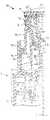
Translated fromKorean제1도, 제2도, 제3도 및 제4도는 본 발명에 따른 압력 펌프의 실시예의 반수직 단면도.1, 2, 3 and 4 are semi-vertical cross-sectional views of an embodiment of a pressure pump according to the invention.
본 발명은 압력 축적형 투사 펌프에 관한 것으로써, 특히 펌프 체임버를 충전시키는데 도움이 되도록 저압력을 가지며 플런저 헤드의 외면에 압력이 가해진 생산물로 재충전 되게하는 컨테이너로부터 생산물을 투사하기 위한 펌프에 관한 것이다.TECHNICAL FIELD The present invention relates to a pressure accumulating projection pump, and more particularly to a pump for projecting a product from a container that has a low pressure to help fill the pump chamber and is refilled with a product that is pressurized on the outer surface of the plunger head. .
특히, 에어로솔용 투사 장치들은 압력이 가해진 생산물로 재충전될 수 있다. 이러한 투사 장치들은 스프레이버튼의 수동압하에 따라 압력이 가해진 생산물을 분사하기 위한 제어 밸브로써 간단히 작동되는데, 지금까지 널리 사용되고 있는 충전 방법은 압력 충전 방법으로써 알려져 있다. 투사된 상기 생산물은 생산물이 대기압하에 있을 때 매우 빠르게 증발하는 형태라든가 또는 생산물의 추진이 질소, 이산화탄소와 같은 불변 가스의 압력하에 있는 컨테이너 상의 액체 조성물을 효과적으로 유지시키는 형태의 추진액체로 압하된다. 상기 압력충전 기술은 선택적인 “코울드-필링방법”(cold-filling method)보다 양호하며, 에어로솔 투사용 이산화탄소, 산화 질소와 같은 용해성 또는 불용성 추진 기체의 사용은 프로판, 부탄과 같은 추진액체 가스의 사용보다 훨씬 더 양호한데, 그 이유는 압하된 가스들이 투사되는 향기나 또는 민감한 약 생산물과 양립할 수 없기 때문이다.In particular, projection devices for aerosols can be refilled with pressurized products. Such projection devices are simply operated as control valves for injecting a product pressurized under the manual pressure of the spray button. The filling method widely used so far is known as a pressure filling method. The projected product is pressed into a propellant liquid in the form of evaporating very quickly when the product is at atmospheric pressure or in the form of the propulsion of the product effectively maintaining the liquid composition on the container under the pressure of a constant gas such as nitrogen, carbon dioxide. The pressure filling technique is better than the optional “cold-filling method” and the use of soluble or insoluble propellant gases, such as carbon dioxide and nitrogen oxides for aerosol projection, may be useful for the propulsion liquid gases such as propane and butane. Much better than use, because the pressed gases are incompatible with the projected aroma or sensitive drug product.
컨테이너에 밀봉하여 있는 이러한 모든 에어로솔 투사기들은 대기에 관통하는 컨테이너를 필요로 하는 공지의 펌프 스프레이보다 더 양호한 장점을 제공해준다. 따라서 공기의 출현을 용납하지 않는 이러한 생산물은 시장에서 에어로솔 투사기들의 많은 형태들 중의 하나를 사용하여 안전하고 효과적으로 사용될 수 있는 어떤 민감성 약제와 같은 산화물이 될 수 있다.All of these aerosol projectors sealed in containers offer better advantages than known pump sprays that require containers to penetrate the atmosphere. Thus, such a product that does not tolerate the emergence of air can be an oxide such as any sensitive agent that can be used safely and effectively using one of many forms of aerosol projectors on the market.
전술한 밸브 제어형 에어로솔 투사기에 필요한 다양성을 만족시키기 위하여 컨테이너에 구멍을 낼 필요가 없는 펌프-형 투사기가 U.S.P. 3,211,346호에 발표되었는데, 그 안의 물질을 펌프 체임버 상으로 흐르도록 하는 불활성 가스의 압력하에 물질이 있기 때문에 컨테이너 상에 구멍을 낼 필요가 없다. 그러나, 이러한 트로틀-형 펌프는 방전이 핑거 액튜에이터 상에 압력을 하강시킴에 따라 서서히 폐쇄되어 원치않는 드리블(dribbles)을 야기하고 방전 효율이 떨어지며, 공기가 핑거 압력의 해방시 펌프 용량을 확대시킴으로써 펌프 체임버 상으로 도입된다는 점에서 상술한 종류의 펌프의 사용에서와 마찬가지로 결점이 제기된다.Pump-type projectors that do not need to be drilled in a container to satisfy the versatility required for the valve-controlled aerosol projector described above are described in U.S.P. 3,211,346, which does not need to be punctured on a container because the material is under the pressure of an inert gas that causes the material to flow onto the pump chamber. However, these throttle-type pumps are slowly closed as the discharge lowers the pressure on the finger actuator, causing unwanted dribbling and lowering the discharge efficiency, and the air expands the pump capacity upon releasing the finger pressure. The drawbacks arise as in the use of pumps of the kind mentioned above in that they are introduced onto the chamber.
계속적인 펌프 개발, 즉 컨테이너 벤트(container vent)를 가지지 않는 압력 빌드-업 스프레이어(pressure build-up sprayer)가 U.S.P. 4,271,875호의 제6도, 제7도에 예시되었는데, 이 장치는 피스톤 업스트로크(up-stroke)동안 피스톤 체임버 속과 딥튜브(dip tube)를 통해 컨테이너 상류로부터 생산물을 인가하기 위한 니트로겐과 같은 압력 가스를 사용하는데 이용된다.압력 유체들이 신축성이 있는 쟈켓을 통해 펌프체임버 외부로부터 투사되는 것과 같이 상기 설비는 이 펌프 투사기를 충전하기 위해 만들어진다. 그러나 이러한 펌프 구조는 본 발명의 기본 발명인 본 출원인의 수동 작동 투사펌프 U.S.P. 4,050,613호의 장점을 제공해주지 못하고 있다. 예를 들면, 본 출원인에 의한, 본워노다 먼저 출원한 특허에서 언급한 바와 같이 단일 플런저 유니트는 다른 부품들과 협동하여 여러 기능, 즉 펌프 실린더, 압력 축적 체임버 피스톤 압력 작동 방전 밸브들의 동작을 수행한다. 전술한 미국 특허원 제121,223호의 유니트 플런저는 컨테이너 벤트 밸브의 기능을 수행하고, 전술한 CIP 출원에서 언급한 바와 같이 플런저의 상부 단부상에 표면을 상호 접하는 피스톤의 설비는 플런저 헤드가 플런저 다운 스트로크 단부 다음에 축적 체임버로부터의 생산물을 계속적으로 방출하게 한다. 특허 CIP 출원에서 컨테이너 벤트 밸브는 측면을 지지하기 위하여 플런저 헤드의 원통부에 보유 비드(retention bead)와 함께 베어링 부재를 제공하기 위하여 플런저 헤드상에 설치되어 방전의 개, 폐의 제한없이 응답하도록 이러한 힘들의 영향으로 부터 플런저를 격리한다. 종래의 기술과 이와 관련하여 개발된 이러한 모든 특징은 압력 충전에 적합한 압력 축적형의 언벤트한 투사기(unvented dispenser)에 합세된다.Ongoing pump development, i.e., pressure build-up sprayers without container vents, is a U.S.P. Illustrated in FIGS. 6 and 7 of 4,271,875, a device such as nitrogen for applying the product from the container upstream through a dip tube and into the piston chamber during piston upstroke. The facility is made to charge this pump projector as the pressure fluids are projected from outside the pump chamber through an elastic jacket. However, this pump structure is the applicant's manually operated projection pump U.S.P. It does not provide the advantages of 4,050,613. For example, as mentioned in the patent application filed earlier by the present applicant, a single plunger unit performs several functions in cooperation with other components: pump cylinder, pressure accumulation chamber piston pressure actuated discharge valves. . The aforementioned unit plunger of U.S. Patent Application No. 121,223 serves as a container vent valve, and as mentioned in the aforementioned CIP application, the provision of a piston for interfacing the surface on the upper end of the plunger has a plunger head with a plunger down stroke end. The product is then continuously discharged from the accumulation chamber. In the patent CIP application, the container vent valve is installed on the plunger head to provide a bearing member with a retention bead in the cylindrical portion of the plunger head to support the side so that it can respond without limitation of opening and closing of the discharge. Isolate the plunger from the effects of the forces. All these features developed in the prior art and in connection with this are combined in a pressure accumulating unvented dispenser suitable for pressure filling.
본 발명의 목적은 전술한 종래 기술과 관련하여 개발된 컨테이너 벤트 압력 빌드-업 스프레이어의 결점을 해소하고 효율적이며 매우 빠른 속도로 유체로 충전된 압력하에 있을 수 있는 압력 축적형의 수동 작동형 투사기를 제공하는데 있다.It is an object of the present invention to overcome the shortcomings of the container vent pressure build-up sprayer developed in connection with the above-mentioned prior art and to be a pressure accumulating manual actuated projector which can be under fluid-filled pressure at an efficient and very high speed. To provide.
본 발명의 다른 목적은 신축성 있는 립 시일을 가지는 환형 스커트가 플린저나 또는 플런저 왕복 운동동안 충전 통로를 폐쇄하기 위한 펌프의 플런저 헤드로부터 연장하고, 이러한 통로는 펌프 몸체내에서 개방함으로써 한정되고 유체의 흐름이 컨테이어 속으로 흐르도록 펌프 몸체상에 정지 피스톤을 둘러싸는 환형벽이 압력이 충전되는 동안 허용되고, 이러한 립 시일은 충전되는 동안 압력하에서만 환형 벽으로부터 떨어져 고정되는 투사기를 제공하는 데 있다.Another object of the present invention is that an annular skirt having an elastic lip seal extends from the plunger head of the pump to close the filling passage during plunger or plunger reciprocating movement, which passage is defined by opening in the pump body and the flow of fluid An annular wall surrounding the stop piston on the pump body to flow into this container is allowed while the pressure is filled, and this lip seal is to provide a projector that is fixed away from the annular wall only under pressure while being filled.
본 발명의 다른 목적은 플런저가 방전의 개방, 폐쇄 동작 기간동안 상부로부터의 수압과 하부로부터의 스프링력에 응답하여 어떤 제한없이 자유로이 플로트 (float)할 수 있도록 상호 동작 기간동안에 플런저 헤드에 대하여 측면적으로 또는 편심적으로 힘을 받는 힘의 영향에 대하여 플런저를 격리하기 위한 안티-쿠킹 플런저 헤드(anti-cocking plunger head)를 가지는 투사 펌프를 제공하는 데 있다.Another object of the present invention is to provide a lateral view of the plunger head during the interoperation period such that the plunger can float freely without any limitation in response to water pressure from the top and spring force from the bottom during the opening and closing operation of the discharge. It is to provide a projection pump having an anti-cocking plunger head for isolating the plunger against the effects of force exerted or eccentrically.
본 발명의 다른 목적은 플런저가 플런저 헤드 다운 스트로크의 단부 앞에 피스톤의 상부 단부에 대하여 저부를 제공하도록 상기 플런저가 상부 단부에서 상호 교차되어 플런저 헤드가 방전을 폐쇄하는 플런저 업스트로크의 개시와 이것의 다운 스트로크의 단부 앞에 축전 체임버로부터 생산물을 계속 방출하는 투사펌프를 제공하는 데 있다.It is a further object of the present invention to initiate the plunger upstroke and its down which the plunger crosses at the top end such that the plunger head closes the discharge so that the plunger provides a bottom relative to the upper end of the piston before the end of the plunger head down stroke. It is to provide a projection pump that continues to discharge the product from the electrical storage chamber before the end of the stroke.
본 발명의 신규한 특징, 장점 및 다른 목적들은 첨부도면을 참조하여 설명한 하기의 기술로부터 명백하게 될 것이다.The novel features, advantages and other objects of the present invention will become apparent from the following description with reference to the accompanying drawings.
제1도의 펌프 어셈블리(10)는 현재의 펌프가 컨테이너 벤트를 가지지 않는 것만을 제외하고 전술한 CIP 출원의 제1도에서 예시된 펌프(10)와 동일하다. 따라서, 상기 어셈블리는 펌프 몸체(11)와 투사되는 압력 생산물의 컨테이너(예시 안됨)의 네크 상에 단단하게 고착되고 일체적으로 형성된 폐쇄된 캡(12)을 포함한다. 펌프 어셈블리는 이산화탄소, 산화 질소 등과 같은 압력 가스를 인가하여 생산물들로 충전된 컨테이너를 가지며, 컨테이너와 생산물을 충전한 다음에 충전선상에 정충전(상술한 방법대로)될 수 있다. 그리고 환형 슬리이브(13)는 펌프 몸체의 상부벽(14)에 의존하여 펌프 몸체와 컨테이너 사이에서 유속의 타이트한 밀봉 효율을 높이기 위하여 컨테이너 네크와 결합되어 연장된다.The
정지되고 속이 빈 업스탠딩 피스톤(upstanding piston)(15)은 컨테이너가 압력 충전되는 것을 통해 압력 충전통로(17)를 한정하기 위해 피스톤의 베이스로부터 약간 떨어져 둘러싸는 환형 벽(16)을 통해 벽(14)상에 일체로 형성된다. 충전부(18)는 슬럼프 드레인이 통로(17)의 저 단부상의 펌프 몸체상에 위치하여 유체가 충전되는 동안 컨테이너에 인입되는 기능을 가진다. 이 부분은 왕복 운동 동안 립 시일에 의해 개방되는 것이 회피되도록 플런저 헤드 다운스트로크의 단부상에 배치된다.The stationary, hollow
상기 피스톤은 종래의 딥 튜브(21)가 어떠한 공지의 방법으로 안착되는 입구 통로(19)를 한정하며 상기튜브는 상기 생산물이 컨테이너로부터 투사되도록 연장된 하부 단부를 가진다. 볼 체크 밸브(22)와 볼 시이트(23)들은 입구를 제어하는 밸브용 피스톤 상부 단부상에 제공되고, 다수의 볼 유지핑거(24)는 흡인스트로크 동안 시이트되지 않도록 피스톤의 상부단부에 제공되고, 다수의 볼 유지핑거(24)는 흡인스트로크 동안 시이트되지 않도록 피스톤의 상부단부에 볼체크 밸브를 둘러싼다. 피스톤의 상부 단부는 가볍게 외부로 플레어하고 실질적으로 신축성이 없는 환형 립 시일(25)에서 종결된다.The piston defines an inlet passage 19 in which a conventional dip tube 21 is seated in any known manner and the tube has a lower end extending so that the product is projected from the container. Ball check valves 22 and ball sheets 23 are provided on the piston upper end for the valve controlling the inlet, and a number of ball retaining fingers 24 are provided at the upper end of the piston so as not to be seated during the suction stroke, A number of ball retaining fingers 24 surround the ball check valve at the upper end of the piston so that it is not seated during the suction stroke. The upper end of the piston terminates in an annular lip seal 25 that is lightly flared outward and is substantially elastic.
내부 보어를 가지는 환형 플런저나 또는 축적기(26)는 가변 체적 펌프 체임버(27)를 한정하기 위하여 정지 피스톤상에 연결된다. 복귀 스프링(28)은 제1도에 예시된 바와 같이 펌프 몸체 위에 전체적으로 상승된 피스톤을 향하여 플런저를 탄력적으로 자극하는 플런저의 저단부와 펌프 몸체의 솔더(29) 사이에서 압하된다.An annular plunger or accumulator 26 with an inner bore is connected on the stop piston to define the variable volume pump chamber 27. The
플런저 헤드(31)는 펌프 체임버(27)와 개방 상태로 연통하는 동봉된 가변 체적 축적 체임버(33)를 한정하고 플런저(26)를 수용하는 하부로 지시된 블라인드 소켓(32)를 가진다. 이 축적 체임버는 펌프 체임버보다 더 큰 직경을 가지며, 플런저의 환형 상부로 나타낸 단부는 복귀 스프링(28)의 상부 트러스트의 반대 위치에 축적 체임버내에서의 유속 압력으로 노출된다.The
플런저 헤드는 상부쪽으로 곧게 일직선으로 뻗는 핑거피이스(34)를 보이도록 형성되어 이것에 인가된 간헐적인 핑거 압력은 정지 피스톤(15)상에서 왕복 운동을 수행하기 위하여 플런저에 전송되며, 플런저의 각 압력은 헤드가 수신되는 핑거 압력으로 플런저를 전체 상승 위치로 복귀시키는 스프링(28)에 의해 억제된다.The plunger head is formed to show a
플런저는 플런저 헤드가 펌프 몸체상의 원추형 부분(37)의 내부 표면을 따라 그 측면으로써 안내되도록 하는 외부 직경을 가지는 방사상으로 외부로 연장한 보유 베드(36)상에서 종결하는 원형 부분(35)을 가진다. 칼라의 상부 단부는 소정의 위치로 플런저 헤드의 이동을 상부로 제한하기 위하여 베드(36)와 협동하는 쉽게 내부로 연장한 보유 베드(38)를 가진다. 하나나 또는 2개의 보유 베드(36)(38)는 유체들이 이하에서 좀 더 상세히 후술하는 방법으로 컨테이너 속으로 충전되는 개방 축 슬로트(예시 않음)가 제공되어 있다.The plunger has a
플런저 헤드는 플런저와 플런저 헤드사이의 환형 스페이스에 의해 한정된 방전 체임버로부터 연장한 그리고 방전오리피스(41)내에서 종결된 방전 통로(39)를 포함한다. 따라서, 투사된 생산물은 펌프 동작 기간동안 축적 체임버로부터 대기속으로 이러한 방전 통로를 통하여 이동되고, 방전 통로가 플런저의 블라인드 상부 단부 하부에 있는 블라인드 소켓속으로 개방되어 이러한 상부 단부가 후자가 스프링(28)에 의해 소켓(32)의 블라인더 단부속으로 제1도에 예시한 바와 같이 전체적으로 상승되는 위치로 돌출될 때 상기 플런저에 의해 정상적으로 커버된다.The plunger head includes a
플런저 헤드의 내면은 체적을 부분적으로 대신하는 펌프 체임버속으로 생산물과 헤드의 전체 부분으로써 윤곽 표면(43)을 이동한다. 이러한 윤곽 표면은 립 시일(25) 뿐만 아니라 볼 체크 밸브와 볼 보유 핑거를 포함하는 피스톤의 상부 단부상의 윤곽을 배치시키도록 형성되어 있다. 따라서 피스톤의 상부 단부와 플런저 헤드의 반대 내부 단부는 보완적으로 윤곽이 형성되어 투사 작동 전에 헤드의 압하 동작 기간동안 직면 윤곽을 가져올 때 방전을 통해 그 안의 어떤 축적된 공기의 추출이 필요하면 프리미임(prime)되고 공기는 동일한 개방을 위하여 방전에 관련된 플런저를 이동하기 위하여 대형 직경 축적기에서 작동되고 압축된다.The inner surface of the plunger head moves the contour surface 43 as a whole part of the product and head into a pump chamber which partially replaces the volume. This contoured surface is configured to position the contour on the upper end of the piston including the lip seal 25 as well as the ball check valve and the ball retaining finger. Thus, the upper end of the piston and the opposite inner end of the plunger head are complementally contoured to prime the surface if it is necessary to extract any accumulated air therein through discharge when bringing the facing contour during the head-down operation of the head before projecting operation. It is primed and the air is operated and compressed in a large diameter accumulator to move the plunger associated with the discharge for the same opening.
환형 밸브 스커트(44)는 플런저 헤드로부터 의존하고 플런저 헤드 왕복 운동을 통해 벽(16)의 내부 표면(26)에 부착되는 환형 립 시일(45)상에서 종결된다. 이러한 내부 표면은 펌프 몸체의 중심축과 같은 축선상에 놓이는 직선 실린더에 의해 한정되어 통로(17)가 펌핑 작동을 통해 립 시일에 의해 폐쇄된 채로 유지된다. 따라서 현재의 펌프 어셈블리는 컨테이너의 윤곽이 컨테이너의 벤트를 요구함이 없이 펌프 체임버속으로 빠르게 흐르는 압축 가스의 영향하에 있는 폐쇄된 시스템이다. 따라서 생산물 오염이 향수와 민감성 약제와 같은 물질이 투사되는 것을 방지하는데 바람직한 곳에서 이산화탄소, 산화 질소와 같은 압력 가스가 상술한 목적을 수행하기 위해 생산물의 자연적인 상태에 따라 선택된 압력으로 이용될 수 있으며, 생산물만이 컨테이너로부터 펌프 체임버로 이동된다.The annular valve skirt 44 terminates on an annular lip seal 45 that is dependent from the plunger head and is attached to the inner surface 26 of the wall 16 via the plunger head reciprocating motion. This inner surface is defined by a straight cylinder lying on the same axis as the central axis of the pump body such that the passage 17 is kept closed by the lip seal through the pumping operation. The current pump assembly is therefore a closed system under the influence of compressed gas flowing rapidly into the pump chamber without the container contour requiring the vent of the container. Thus, where product contamination is desirable to prevent the projection of substances such as perfumes and sensitive agents, pressure gases such as carbon dioxide and nitric oxide can be used at pressures selected according to the natural state of the product to accomplish the aforementioned purposes. Only the product is transferred from the container to the pump chamber.
플런저나 또는 축적기(26)의 상단부는 제1도의 플런저의 방전 밸브 폐쇄 위치와 플런저 헤드 상부 단부에 의지하여 링(48)의 외부 표면에 밀봉된 외부적으로 연장한 플랜지(47)를 가진다. 상기 플런저의 하부 단부는 내부표면 스커트(44)와 일체로 밀봉되고 방전 체임버(42)와 한계를 정하고 있고 립 시일(49)을 한정하기 위해 구부러져 있다. 이러한 장치에 있어서 립 시일(49)의 종단부는 방전 통로(39)하부에 놓여있어 플런저와 플랜지(47)로써 방전을 개방하는 헤드 사이를 간단하게 이동시켜 링(48)으로부터 떨어져 이동된다. 따라서 급속 개방 방전이 가능하게 된다.The upper end of the plunger or accumulator 26 has an externally extending flange 47 sealed to the outer surface of the
전술한 펌프 어셈블리는 본발명의 펌프 어셈블리가 컨테이너 벤팅이 필요 없는 폐쇄된 시스템을 구성한다는 점을 제외하고는 상술한 본 출원인의 CIP 출원의 펌프 어셈블리와 동일한 구성으로 되어 있다. 부품(35)(44)들과 함께 플런저 헤드(31)는 플런저 헤드의 왕복 운동을 통하여 그것의 부품(15)(16)(37)들을 포함하는 펌프 몸체의 축과 동일한 축 위치를 가진다. 플런저 헤드상에 위치한 보유 베스(38)와 립 시일(45)는 컬러(37)와 벽(16)의 내부 표면을 따라 그들이 일체로 작동한다. 따라서 플런저 헤드는 스톱 리미트들 사이에 축의 방향으로 왕복 운동을 행하며 컬러(37), 통로(17), 정지 위치 피스톤을 포함하는 펌프몸체 축과 일치하는 축들을 유지한다. 이러한 측면 축 제어로 플런저 헤드는 그 축들을 쿡(cook)함이 없이 여러 비-축력을 인가 받게 되거나 축 합동성을 잃게 된다. 따라서 왕복 운동 동안 플런저 헤드에 인가되는 편심력은 플런저에 보유력을 인가하거나 또는 어떤 바이어스력을 가함으로써 방지될 수 있다. 따라서 방전 밸브로써 작동하는 플런저는 상위 수압과 하위 스프링력을 자유로이 플로트 하기 위해 만들어진 것으로 이러한 힘들에 응답하여 이동에 대하여 억제되지 않는다.The pump assembly described above is of the same construction as the pump assembly of the applicant's CIP application described above, except that the pump assembly of the present invention constitutes a closed system that does not require container venting. The
플런저 헤드 상에 편심력은 플런저와 그 밸브 사이의 마찰 부하를 감소시켜 플런저가 방전 통로에 남아 있는 생산물의 작은 질량으로 플런저 다운스트로크의 단부에서 개방되게 하는 효과가 있다. 상기 헤드 상에 작용력이 구제될 때 브레이크나 또는 마찰 유지력은 이완되어 스프링이 플런저를 폐쇄된 위치로 이동되게 한다. 따라서 플런저 방전 스트로크의 단부상의 방전 통로에 남아있는 생산물의 소량은 플런저 인테이크 스트로크 개시시 깨끗해져 플런저가 스프링 압력에 응답하여 폐쇄된다. 재방전 스트로크 개시시 기대치 않은 이러한 방전은 불편하기 때문에 피해져야 한다. 본 발명에 따라서 플런저가 측면 압력에 따른 마찰 개입에 의해 전체적으로 또는 부분적으로 억제될 수 없기 때문에 유압과 스프링력 사이의 균형하에서 만들어진 연속적 일시적으로 동작에 응답하게 된다.The eccentric force on the plunger head has the effect of reducing the frictional load between the plunger and its valve, allowing the plunger to open at the end of the plunger downstroke with a small mass of product remaining in the discharge passage. When the action force is relieved on the head, the brake or frictional holding force relaxes causing the spring to move the plunger to the closed position. Thus, a small amount of product remaining in the discharge passage on the end of the plunger discharge stroke is cleared at the start of the plunger intake stroke and the plunger is closed in response to the spring pressure. This unexpected discharge at the start of the re-discharge stroke should be avoided because it is inconvenient. According to the present invention, the plunger cannot be suppressed in whole or in part by frictional intervention in accordance with the lateral pressure, thereby responding to a continuous, transient operation made under the balance between hydraulic pressure and spring force.
현재의 펌프 어셈블리의 동작은 컨테이너 내의 생산물의 압력가스의 영향하에 있다는 사실만을 제외하고는 본 출원인의 U.S.P. 제4,050,613호와 전술한 출원에서 언급한 것과 동일하게 작동한다. 따라서 플런저 방전 단수에서 폐쇄된 방전을 가진 플런저 업스트로크는 펌프 체임버를 확장하고 국부적인 진공을 발생시켜 압축된 가스의 압력이 딥튜브와 펌프 체임버를 통해 생산물에 인가되고 입구볼 체크 밸브를 언시이트(unseat)한다. 컨테이너에서 투사되는 생산물은 압축된 가스의 나머지를 그 안에 보유하는 헤드스페이스 상에 압축된 가스의 부분을 그 안에서 용해한다. 따라서 컨테이너내의 생산물은 비워질 때까지 압축된 가스의 영향하에 남게된다. 그리고 하부로 플런저 왕복 운동 동안 발생된 펌프 체임버내의 수압 방전압력은 컨테이너 내의 내부 압력과 복귀 스프링의 합력로 초과하여야 이러한 수압이 축척 체임버 내에서 작동하는 방전 개방 압력을 창출하는 것과 동일하게 방전 개방에 영향을 미친다. 플런저의 상부 단부에 위치한 플랜지(47)는 현재의 압력 빌드-업 스프레이 펌프의 디자인 방전 압력에까지 컨테이너 압력이 견딜 수 있는 밀봉된 방전 밸브를 한정한다.The operation of the present pump assembly is based on the applicant's U.S.P. It works the same as mentioned in No. 4,050,613 and the above-mentioned application. Thus, the plunger upstroke with closed discharge in the plunger discharge stage expands the pump chamber and generates a local vacuum so that the pressure of the compressed gas is applied to the product through the diptube and pump chamber and the inlet ball check valve unseat). The product projected from the container dissolves therein a portion of the compressed gas on the headspace that holds the rest of the compressed gas therein. The product in the container therefore remains under the influence of the compressed gas until it is empty. And the hydraulic discharge pressure in the pump chamber generated during the plunger reciprocating downwards must be exceeded by the combined force of the internal pressure in the container and the return spring to affect the discharge opening in the same way that this hydraulic pressure creates a discharge opening pressure operating in the scale chamber. Crazy Flange 47 located at the upper end of the plunger defines a sealed discharge valve that can withstand container pressure up to the design discharge pressure of current pressure build-up spray pumps.
현재의 펌프 어셈블리는 그안의 압축된 추진 가스를 가지는 생산물로 채워진 컨테이너에 응용되거나 또는 컨테이너에 스프레이가 인가된 후 그리고 충전된 후 충전 상태에서 충전될 수 있다. 종래의 에어로솔 충전선로상에 사용된 것과 같은 충전헤드(51)는 제1도에 예시된 바와 같이 편리한 위치에 밀봉 방법으로 펌프 어셈블리상에 연결된다. 상기 도면에서 굵게 표시한 화살표는 보유 비드들의 흠들을 유체의 충전통로를 나타낸 것으로 방전 헤드가 방전압력에 의해 기계적으로 압하된다.Current pump assemblies may be applied to a container filled with a product having a compressed propellant gas therein or filled in a filled state after spraying and filling the container. Filling heads 51, such as those used on conventional aerosol charging lines, are connected on the pump assembly in a sealing manner at a convenient location as illustrated in FIG. Arrows in bold in the figure indicate the passage of the fluid filling the defects of the holding beads, the discharge head is mechanically reduced by the discharge pressure.
벽(16)의 내부 표면(46)과 접속하여 있는 환형 립 시일(45)은 포지티브 가스 압력하에 액체든지 또는 기체든지 간에 어떠한 내용물을 내포하고 있는 컨테이너로 부터 상기 내용물들이 인출되는 것을 방지한다 그러나 이러한 립 시일이 충전되는 동안 충분히 탄력이 있으면 상기 시일(45)의 충전압력은 립 시일을 바이패스 하도록 컨테이너 내의 압력을 인가하여 충전 유체가 포트(18)를 통해 컨테이너에 유입되도록 상기립시일이 표면(46)으로부터 약간 떨어져 안으로 구부러져 있다. 충전된 다음에 상기 립 시일(45)의 내부표면에 대하여 동작하는 고압력은 충전 장치가 제거될 때 상기 밸브가 대기압에 복귀되는 것처럼 부재(46)에 대하여 밀봉 연결되어 있는 그안에 유지 된다.The annular lip seal 45 in contact with the inner surface 46 of the wall 16 prevents the contents from being drawn out of a container containing any contents, whether liquid or gas under positive gas pressure. If the lip seal is sufficiently resilient while being filled, the filling pressure of the seal 45 applies a pressure in the container to bypass the lip seal so that the fill seal enters the surface through the
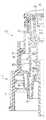
제2도에 도시된 바와 같이 펌프 어셈블리(10A)는 펌프 어셈블리(10)와 실질적으로 동일하기 때문에 상기 펌프 어셈블리(10)와 동일한 예시번호를 병기하여 표기하였다. 그러나 상기 실시예에서 플런저(26a)는 시일(45)에서 종결되는 스커트 (44a)를 포함하기 때문에 제1도에 예시한 자유로운 플로팅을 만들지 못한다. 다시말해서 펌프 어셈블리는 제1도에 관하여 언급한 바와 같이 동일하게 작동 하지만 컨테이너는 충전 통로를 나타내는 화살표에 의해 예시한 바와 같이 충전 장치(51)의 사용으로 충전된다. 따라서 립 시일(45)는 유체가 단자(18)를 통해 컨테이너로 인입되는 동안 표면(46)으로부터 상방향으로 떨어져 구부러져 있고, 충전장치가 제거될 때 표면(46)에 대하여 밀봉 폐쇄되어 있다.As shown in FIG. 2, the
제3도에 예시된 펌프 어셈블리(10B)는 플런저(26b)의 상부 단부가 서로 다르게 구성되어 있다는 사실만을 제외하고는 어셈블리(10)과 실질적으로 동일하다. 이것의 자유 플로팅 특성에 부과하여 플런저 다운 스트로크의 단부에 있는 플런저 헤드 하에 그 자신이 리시이트 되며, 재충전이 시작된 다음에 플런저 재충전 스트로크가 방전 분출을 피하기 전에 생산물은 재충전 스트로크의 개시전에 축적 체임버로부터 세척된다. 이러한 목적을 위하여 제1도의 표면(43)과 동일한 상호 직면한 윤곽 표면(43a)은 일체적으로 플런저의 상부 단부에 제공된다. 상기 표면은 플런저 헤드의 내측면으로부터 예시번호 52에서 약간 격리된 커버벽을 가지는데, 상기 커버벽은 펌프 체임버와 축적 체임버 사이의 개방통신을 유지하기 위한 다수의 단자(53)들을 가진다. 따라서 플런저 헤드의 압하시 윤곽 표면(43a)은 정지 피스톤에 대하여 밑바닥에 있고 플런저 헤드 앞의 볼 체크 밸브는 방전 스트로크의 단부에 도달한다. 플런저 헤드 압하시 축적체임버 내의 수압은 헤드의 다운 스트로크 동안 플런저로 부터 약간 떨어져 위치한 헤드를 유지하여 다운 스트로크가 계속됨에 따라 헤드는 정상의 방전스트로크의 부분으로써 플런저 상부에서 생산물을 추출하는 윤곽 핑거력에 의해 수압에 대하여 하향으로 이동된다. 따라서 “에프터 스프레이”(after spray)가 방전 스트로크의 단부에서의 플런저 폐쇄 동작을 기계적으로 지지함으로써 피해져 방전 스트로크의 단부에서의 방전을 통해 생산물의 드리핑(dripping)이나 드라이블링(dribbling)을 피할 수 있다.The pump assembly 10B illustrated in FIG. 3 is substantially the same as the
다시말해서, 제1도에 도시한 바와 같이 플런저 헤드의 내부 측면상에 수용된 윤곽표면(43)과 헤드의 이러한 상호 직면 윤곽이 플런저의 개방 상부 단면상에 돌출되어 헤드 내부 안쪽은 정지 피스톤의 상부단부에 대하여 밑면에 있고, 볼은 방전스트로크의 단부에 있는 부재를 체크 한다. 따라서 오리피스(41)가 제어 디자인 압력의 용량을 방전 시키는 바를 초과하는 펌프비를 발생하는 속도로 방전 스트로크에 영향을 준다. 따라서 상호 직면 윤곽은 방전 스트로크의 저부에 도달하는 반면에 플런저는 방전 밸브 개방모드에 있게 되어 헤드 내의 시이트로 부터 변위 되며, 압력비로 방전을 계속하고 스프링력이 축적기를 헤드의 내부에 대하여 폐쇄된 밸브 위치에 복귀 시키기 때문에 축적된 생산물을 추출한다. 밸브가 폐쇄된 다음에 이러한 계속적인 방전은 ″에프터 스프레이″로써 상술한 바와 같이 행한다.In other words, as shown in FIG. 1, the contour surface 43 received on the inner side of the plunger head and this mutually facing contour of the head protrude on the open upper end face of the plunger so that the inner inside of the head is connected to the upper end of the stop piston. On the bottom, the ball checks the member at the end of the discharge stroke. The orifice 41 thus affects the discharge stroke at a rate that results in a pump ratio that exceeds the discharge capacity of the control design pressure. The cross-facing contour thus reaches the bottom of the discharge stroke while the plunger is in the discharge valve open mode, displaced from the seat in the head, continuing to discharge at a pressure ratio and the spring force closing the accumulator against the inside of the head. To return to the location, the accumulated product is extracted. This continuous discharge is performed as described above with " after spray " after the valve is closed.
제3도의 실시예에서, 상호 직면 공기 변위일체 윤곽을 가지며 디펜팅 스커트가 없는 플런저 부재는 정상적인 마찰 계수에 수압과 스프링을 더한 값에 응답하는 자유 플로팅부재가 된다. 플런저 헤드는 통로(17)의 내부 표면(46)과 밀봉 연결되는 립 시일(45)과 환형 스커트(44b)를 수용하여 펌핑 동작동안 폐쇄된 통로를 유지할 뿐만 아니라 헤드 보유 베드(36)와 협력하는 일체 가이드로써 작동한다. 따라서 직면부품에 관련하여 슬라이드(slide)하는 펌프 어셈블리의 각 부품은 다른 협동 부품들과 함께 축의 합치로 유지되어 불필요한 윤곽-생산물 커플들을 제거한다.In the embodiment of FIG. 3, the plunger member having an integrally facing air displacement integral contour and without a deflecting skirt is a free floating member responsive to the normal friction coefficient plus hydraulic pressure and spring. The plunger head accommodates the lip seal 45 and the annular skirt 44b sealingly connected to the inner surface 46 of the passage 17 to maintain a closed passage during the pumping operation as well as cooperate with the
제4도의 펌프 어셈블리(10c)는 스커트(44c)가 상술한 바와 같이 통로(17)를 폐쇄하기 위하여 플런저(26c)로 부터 연장되는 점만을 제외하고 제2도의 펌프 어셈블리와 비교된다. 그러나 제3도의 표면(43b)과 동일한 윤곽표면(43c)은 일체 부분으로써 플런저(26c)의 상부 단부에 제공되어 제3도에서 언급한 바와 동일한 방법으로 작동된다.The pump assembly 10c of FIG. 4 is compared with the pump assembly of FIG. 2 except that the
전술한 바와 같이 펌프 어셈블리 실시예의 플런저와 플런저 헤드는 전술한 CIP 출원의 실시예의 플런저헤드와 플런저와 상호 교환할 수 있도록 동일하다. 상술한 여러 실시예의 펌프 몸체는 CIP 출원의 펌프어셈블리에 관련하여 수정이 필요한데, 이것은 현재의 어셈블리를 압력이 가해진 컨테이너로 이용 되도록 폐쇄된 시스템을 만들을 필요성 때문이다.As described above, the plunger and plunger head of the pump assembly embodiment are identical to be interchangeable with the plunger head and plunger of the embodiment of the aforementioned CIP application. The pump body of the various embodiments described above requires modification in connection with the pump assembly of the CIP application because of the need to make a closed system to use the current assembly as a pressurized container.
본 발명의 상술한 교시의 관점에서 많은 수정과 변형예가 있을 수 있다. 따라서 첨부된 청구범위의 영역내에서 상술한 특정한 기술 이외에 다른 실시예가 있을 수 있음이 명백하다.There may be many modifications and variations in light of the above teachings of the invention. It is therefore evident that there may be other embodiments in addition to the specific techniques described above within the scope of the appended claims.
Claims (14)
Translated fromKoreanApplications Claiming Priority (2)
| Application Number | Priority Date | Filing Date | Title |
|---|---|---|---|
| US502272 | 1983-06-08 | ||
| US06/502,272US4503997A (en) | 1983-06-08 | 1983-06-08 | Dispensing pump adapted for pressure filling |
Publications (2)
| Publication Number | Publication Date |
|---|---|
| KR850000280A KR850000280A (en) | 1985-02-26 |
| KR870001196B1true KR870001196B1 (en) | 1987-06-20 |
Family
ID=23997080
Family Applications (1)
| Application Number | Title | Priority Date | Filing Date |
|---|---|---|---|
| KR1019840003226AExpiredKR870001196B1 (en) | 1983-06-08 | 1984-06-08 | Dispensing pump adapted for pressure filling |
Country Status (15)
| Country | Link |
|---|---|
| US (1) | US4503997A (en) |
| JP (1) | JPS6013667A (en) |
| KR (1) | KR870001196B1 (en) |
| AU (1) | AU555266B2 (en) |
| BE (1) | BE899863A (en) |
| CA (1) | CA1230867A (en) |
| DE (1) | DE3420961A1 (en) |
| DK (1) | DK162489C (en) |
| FR (1) | FR2547363B1 (en) |
| GB (1) | GB2141185B (en) |
| GR (1) | GR81573B (en) |
| IE (1) | IE55566B1 (en) |
| IT (1) | IT1178396B (en) |
| LU (1) | LU85398A1 (en) |
| NL (1) | NL8401809A (en) |
Families Citing this family (20)
| Publication number | Priority date | Publication date | Assignee | Title |
|---|---|---|---|---|
| US4640443A (en)* | 1983-06-08 | 1987-02-03 | Corsette Douglas Frank | Manually operated dispensing pump |
| GB8625491D0 (en)* | 1986-10-24 | 1986-11-26 | Bespak Plc | Discharge pump assembly |
| FR2620052B1 (en)* | 1987-09-09 | 1990-04-27 | Valois | MANUAL PUMP TYPE PREPRESSURE VAPORIZER FOR USE WITH A PROPELLANT GAS |
| US4838461A (en)* | 1988-04-14 | 1989-06-13 | Owens-Illinois Closure Inc. | Dispensing package for a viscous product |
| US5505343A (en)* | 1994-10-19 | 1996-04-09 | Knickerbocker; Michael G. | Manually actuated pump |
| US5503306A (en)* | 1994-10-19 | 1996-04-02 | Aptar Group, Inc. | Manually actuated pump |
| DE4438364A1 (en)* | 1994-10-27 | 1996-05-02 | Pfeiffer Erich Gmbh & Co Kg | Discharge device for media and method and device for filling a discharge device |
| DE19715712C2 (en)* | 1997-04-15 | 2002-10-31 | Berner Torantriebe Gmbh | sectional |
| US5839617A (en)* | 1997-07-29 | 1998-11-24 | Owens-Illinois Closure Inc. | Pump dispenser |
| US5839616A (en)* | 1997-08-14 | 1998-11-24 | The Procter & Gamble Company | Blow molded container having pivotal connector for an actuation lever |
| DE19807922A1 (en)* | 1998-02-25 | 1999-08-26 | Pfeiffer Erich Gmbh & Co Kg | Media Donor |
| DE19845910A1 (en)* | 1998-10-06 | 2000-04-13 | Pfeiffer Erich Gmbh & Co Kg | Media Donor |
| US6308865B1 (en)* | 2000-10-24 | 2001-10-30 | Hui-Yu Lin | Container-mounted pump means with external restoring spring |
| CN1283365C (en)* | 2001-09-21 | 2006-11-08 | 艾里希普费弗工程师有限公司 | Dosing device with a medium container and a pump mechanism for the container |
| FR2862106B1 (en)* | 2003-11-07 | 2007-08-24 | Valois Sas | FLUID PRODUCT DELIVERY PUMP. |
| FR2871786B1 (en)* | 2004-06-16 | 2007-08-10 | Valois Sas | DEVICE FOR DISPENSING FLUID PRODUCT |
| FR2911175B1 (en)* | 2007-01-08 | 2009-05-08 | Taema Sa | PROTECTIVE HAT MOUNTING FLANGE AND STORAGE AND GAS DELIVERY ASSEMBLY HAVING SUCH A FLANGE |
| FR3003480B1 (en)* | 2013-03-22 | 2016-12-23 | Aptar France Sas | RECHARGEABLE FLUID PRODUCT DISPENSER. |
| CN103452790A (en)* | 2013-08-20 | 2013-12-18 | 米顿罗工业设备(上海)有限公司 | Middle-high pressure inlet plunger pump head structure for metering pump |
| KR101657945B1 (en)* | 2015-05-06 | 2016-09-20 | 주식회사 디에이치콘트롤스 | Hydraulic actuator for quarter-turn valve |
Family Cites Families (13)
| Publication number | Priority date | Publication date | Assignee | Title |
|---|---|---|---|---|
| US3232324A (en)* | 1963-01-18 | 1966-02-01 | American Lecithin Co | Method and apparatus for filling aerosol dispensers |
| US3211346A (en)* | 1964-07-15 | 1965-10-12 | Meshberg Philip | Pump-type dispenser |
| US3651997A (en)* | 1970-03-23 | 1972-03-28 | Risdon Mfg Co | Combined pressure filling and dispensing control valve for aerosol containers |
| US3995666A (en)* | 1975-12-24 | 1976-12-07 | Vca Corporation | Method for filling aerosol spray dispensers |
| US4274560A (en)* | 1976-04-30 | 1981-06-23 | Emson Research Incorporated | Atomizing pump dispenser |
| US4050613A (en)* | 1976-08-31 | 1977-09-27 | Corsette Douglas Frank | Manual actuated dispensing pump |
| US4271990A (en)* | 1978-05-12 | 1981-06-09 | Security Plastics, Inc. | Pumping system for dispensing product from a container |
| US4271875A (en)* | 1978-09-21 | 1981-06-09 | Philip Meshberg | Dispenser adapted for fast pressure filling |
| US4218198A (en)* | 1978-11-02 | 1980-08-19 | Security Plastics, Inc. | Pump having non-throttling peripheral valve |
| US4220265A (en)* | 1979-02-21 | 1980-09-02 | Ethyl Corporation | Pressure fillable dispensing device |
| US4402432A (en)* | 1980-02-13 | 1983-09-06 | Corsette Douglas Frank | Leak-proof dispensing pump |
| US4343417A (en)* | 1980-02-13 | 1982-08-10 | Corsette Douglas Frank | Dispensing pump locking means |
| JPS5756066A (en)* | 1980-09-22 | 1982-04-03 | Yoshino Kogyosho Co Ltd | Spray |
- 1983
- 1983-06-08USUS06/502,272patent/US4503997A/ennot_activeExpired - Lifetime
- 1984
- 1984-05-21IEIE1263/84Apatent/IE55566B1/ennot_activeIP Right Cessation
- 1984-05-22GRGR74790Apatent/GR81573B/elunknown
- 1984-06-01AUAU28931/84Apatent/AU555266B2/ennot_activeCeased
- 1984-06-01DKDK274584Apatent/DK162489C/enactive
- 1984-06-04GBGB08414173Apatent/GB2141185B/ennot_activeExpired
- 1984-06-05CACA000455851Apatent/CA1230867A/ennot_activeExpired
- 1984-06-06NLNL8401809Apatent/NL8401809A/ennot_activeApplication Discontinuation
- 1984-06-06DEDE19843420961patent/DE3420961A1/enactiveGranted
- 1984-06-06LULU85398Apatent/LU85398A1/enunknown
- 1984-06-07ITIT48337/84Apatent/IT1178396B/enactive
- 1984-06-08BEBE0/213097Apatent/BE899863A/ennot_activeIP Right Cessation
- 1984-06-08FRFR8409006Apatent/FR2547363B1/ennot_activeExpired
- 1984-06-08KRKR1019840003226Apatent/KR870001196B1/ennot_activeExpired
- 1984-06-08JPJP59118078Apatent/JPS6013667A/enactiveGranted
Also Published As
| Publication number | Publication date |
|---|---|
| US4503997A (en) | 1985-03-12 |
| DE3420961A1 (en) | 1984-12-13 |
| DK162489C (en) | 1992-03-30 |
| AU2893184A (en) | 1984-12-13 |
| GB2141185B (en) | 1986-12-17 |
| GR81573B (en) | 1984-12-11 |
| DE3420961C2 (en) | 1989-09-21 |
| IT1178396B (en) | 1987-09-09 |
| IE841263L (en) | 1984-12-08 |
| CA1230867A (en) | 1987-12-29 |
| DK274584A (en) | 1984-12-09 |
| LU85398A1 (en) | 1984-11-30 |
| JPH0346384B2 (en) | 1991-07-16 |
| BE899863A (en) | 1984-10-01 |
| IT8448337A0 (en) | 1984-06-07 |
| IE55566B1 (en) | 1990-11-07 |
| FR2547363B1 (en) | 1989-07-21 |
| GB2141185A (en) | 1984-12-12 |
| NL8401809A (en) | 1985-01-02 |
| DK274584D0 (en) | 1984-06-01 |
| DK162489B (en) | 1991-11-04 |
| AU555266B2 (en) | 1986-09-18 |
| JPS6013667A (en) | 1985-01-24 |
| KR850000280A (en) | 1985-02-26 |
| FR2547363A1 (en) | 1984-12-14 |
| GB8414173D0 (en) | 1984-07-11 |
Similar Documents
| Publication | Publication Date | Title |
|---|---|---|
| KR870001196B1 (en) | Dispensing pump adapted for pressure filling | |
| US5518377A (en) | Vertical metering pump having piston biasing elastomeric gasket | |
| US4402432A (en) | Leak-proof dispensing pump | |
| JP3372166B2 (en) | Pre-compression pump type spray | |
| US5458289A (en) | Liquid dispensing apparatus with reduced clogging | |
| JP3679977B2 (en) | Trigger-actuated pump sprayer and its discharge valve assembly | |
| US4596344A (en) | Manually actuated dispenser | |
| US5649649A (en) | Pump for delivering atomized liquids | |
| RU2243146C2 (en) | Double-spring precompression pump with filling-in feature | |
| JPS6027470Y2 (en) | pump dispenser | |
| US5850948A (en) | Finger-operable pump with piston biasing post | |
| US4494680A (en) | Manually operated dispensing pump | |
| JPH05192613A (en) | Liquid pump distributor | |
| US4692103A (en) | Precise output pump sprayer | |
| EP0484615A1 (en) | Manually operated pump device for dispensing fluids | |
| EP1161387B1 (en) | Atomizing pump spray | |
| US5323933A (en) | Atomizer micorpump for liquids | |
| EP0689876A1 (en) | Pump sprayer with stationary discharge | |
| EP0484616A1 (en) | Manually operated pump device for dispensing fluids | |
| KR20030020286A (en) | Manually actuated pump assembly |
Legal Events
| Date | Code | Title | Description |
|---|---|---|---|
| PA0109 | Patent application | St.27 status event code:A-0-1-A10-A12-nap-PA0109 | |
| R17-X000 | Change to representative recorded | St.27 status event code:A-3-3-R10-R17-oth-X000 | |
| PG1501 | Laying open of application | St.27 status event code:A-1-1-Q10-Q12-nap-PG1501 | |
| A201 | Request for examination | ||
| PA0201 | Request for examination | St.27 status event code:A-1-2-D10-D11-exm-PA0201 | |
| G160 | Decision to publish patent application | ||
| PG1605 | Publication of application before grant of patent | St.27 status event code:A-2-2-Q10-Q13-nap-PG1605 | |
| E701 | Decision to grant or registration of patent right | ||
| PE0701 | Decision of registration | St.27 status event code:A-1-2-D10-D22-exm-PE0701 | |
| GRNT | Written decision to grant | ||
| PR0701 | Registration of establishment | St.27 status event code:A-2-4-F10-F11-exm-PR0701 | |
| PR1002 | Payment of registration fee | St.27 status event code:A-2-2-U10-U11-oth-PR1002 Fee payment year number:1 | |
| PR1001 | Payment of annual fee | St.27 status event code:A-4-4-U10-U11-oth-PR1001 Fee payment year number:4 | |
| PR1001 | Payment of annual fee | St.27 status event code:A-4-4-U10-U11-oth-PR1001 Fee payment year number:5 | |
| PR1001 | Payment of annual fee | St.27 status event code:A-4-4-U10-U11-oth-PR1001 Fee payment year number:6 | |
| FPAY | Annual fee payment | Payment date:19930319 Year of fee payment:7 | |
| PR1001 | Payment of annual fee | St.27 status event code:A-4-4-U10-U11-oth-PR1001 Fee payment year number:7 | |
| LAPS | Lapse due to unpaid annual fee | ||
| PC1903 | Unpaid annual fee | St.27 status event code:A-4-4-U10-U13-oth-PC1903 Not in force date:19940621 Payment event data comment text:Termination Category : DEFAULT_OF_REGISTRATION_FEE | |
| PC1903 | Unpaid annual fee | St.27 status event code:N-4-6-H10-H13-oth-PC1903 Ip right cessation event data comment text:Termination Category : DEFAULT_OF_REGISTRATION_FEE Not in force date:19940621 | |
| P22-X000 | Classification modified | St.27 status event code:A-4-4-P10-P22-nap-X000 |