KR870000849B1 - Electronic door key - Google Patents
Electronic door keyDownload PDFInfo
- Publication number
- KR870000849B1 KR870000849B1KR1019850001940AKR850001940AKR870000849B1KR 870000849 B1KR870000849 B1KR 870000849B1KR 1019850001940 AKR1019850001940 AKR 1019850001940AKR 850001940 AKR850001940 AKR 850001940AKR 870000849 B1KR870000849 B1KR 870000849B1
- Authority
- KR
- South Korea
- Prior art keywords
- key
- signal
- contact
- hole
- power supply
- Prior art date
- Legal status (The legal status is an assumption and is not a legal conclusion. Google has not performed a legal analysis and makes no representation as to the accuracy of the status listed.)
- Expired
Links
Images


Classifications
- E—FIXED CONSTRUCTIONS
- E05—LOCKS; KEYS; WINDOW OR DOOR FITTINGS; SAFES
- E05B—LOCKS; ACCESSORIES THEREFOR; HANDCUFFS
- E05B49/00—Electric permutation locks; Circuits therefor ; Mechanical aspects of electronic locks; Mechanical keys therefor
- G—PHYSICS
- G07—CHECKING-DEVICES
- G07C—TIME OR ATTENDANCE REGISTERS; REGISTERING OR INDICATING THE WORKING OF MACHINES; GENERATING RANDOM NUMBERS; VOTING OR LOTTERY APPARATUS; ARRANGEMENTS, SYSTEMS OR APPARATUS FOR CHECKING NOT PROVIDED FOR ELSEWHERE
- G07C9/00—Individual registration on entry or exit
- G07C9/00174—Electronically operated locks; Circuits therefor; Nonmechanical keys therefor, e.g. passive or active electrical keys or other data carriers without mechanical keys
- G07C9/00182—Electronically operated locks; Circuits therefor; Nonmechanical keys therefor, e.g. passive or active electrical keys or other data carriers without mechanical keys operated with unidirectional data transmission between data carrier and locks
- B—PERFORMING OPERATIONS; TRANSPORTING
- B60—VEHICLES IN GENERAL
- B60R—VEHICLES, VEHICLE FITTINGS, OR VEHICLE PARTS, NOT OTHERWISE PROVIDED FOR
- B60R25/00—Fittings or systems for preventing or indicating unauthorised use or theft of vehicles
- B60R25/01—Fittings or systems for preventing or indicating unauthorised use or theft of vehicles operating on vehicle systems or fittings, e.g. on doors, seats or windscreens
- B60R25/04—Fittings or systems for preventing or indicating unauthorised use or theft of vehicles operating on vehicle systems or fittings, e.g. on doors, seats or windscreens operating on the propulsion system, e.g. engine or drive motor
- G—PHYSICS
- G07—CHECKING-DEVICES
- G07C—TIME OR ATTENDANCE REGISTERS; REGISTERING OR INDICATING THE WORKING OF MACHINES; GENERATING RANDOM NUMBERS; VOTING OR LOTTERY APPARATUS; ARRANGEMENTS, SYSTEMS OR APPARATUS FOR CHECKING NOT PROVIDED FOR ELSEWHERE
- G07C9/00—Individual registration on entry or exit
- G07C9/00174—Electronically operated locks; Circuits therefor; Nonmechanical keys therefor, e.g. passive or active electrical keys or other data carriers without mechanical keys
- G07C2009/00753—Electronically operated locks; Circuits therefor; Nonmechanical keys therefor, e.g. passive or active electrical keys or other data carriers without mechanical keys operated by active electrical keys
- G07C2009/00761—Electronically operated locks; Circuits therefor; Nonmechanical keys therefor, e.g. passive or active electrical keys or other data carriers without mechanical keys operated by active electrical keys with data transmission performed by connected means, e.g. mechanical contacts, plugs, connectors
Landscapes
- Engineering & Computer Science (AREA)
- Mechanical Engineering (AREA)
- Computer Networks & Wireless Communication (AREA)
- Physics & Mathematics (AREA)
- General Physics & Mathematics (AREA)
- Lock And Its Accessories (AREA)
Abstract
Translated fromKoreanDescription
Translated fromKorean제1도는 본 발명에 있어서 자동차의 록크 회로도.1 is a lock circuit diagram of an automobile in the present invention.
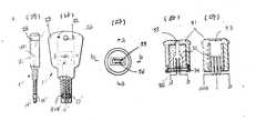
제2도는 직접 신호 발생식 키 회로도.2 is a direct signal generation key circuit diagram.
제3도는 광선식 키 회로도.3 is a radial key circuit diagram.
제4도는 수광식 키 구멍의 회로도.4 is a circuit diagram of a light receiving key hole.
제5도는 본 발명에 있어서 자동차 운전자의 알콜 농도 측정회로도.5 is an alcohol concentration measurement circuit diagram of a motor vehicle driver in the present invention.
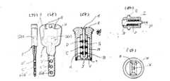
제6도는 직접신호 발생식(접점 수직식) 키와 키 구멍의 구조도로써,6 is a structural diagram of a direct signal generation (contact vertical) key and key hole,
a)는 키의 일부 측 단면도.a) is a partial side cross-sectional view of a key.
b)는 키의 일부 단면도.b) is a partial cross-sectional view of the key.
c)는 키 구멍의 종 단면도.c) is a longitudinal section of the keyhole.
d)는 키 구멍에 있어서 작동편의 확대 단면도.d) is an enlarged cross-sectional view of the operating piece in the key hole.
e)는 키 구멍의 평면도이다.e) is a plan view of the key hole.
제7도는 직접신호 발생식(접점 수평식)키와 키 구멍의 구조도로써,7 is a structural diagram of a direct signal generating (contact horizontal) key and key hole,
a)는 키의 일부 측 단면도.a) is a partial side cross-sectional view of a key.
b)는 키의 일부 종 단면도.b) A partial longitudinal cross section of the key.
c)는 키 단멍의 평면도.c) a top view of a keyhole.
d)는 c)의 a-a선 단면도.d) is a-a cross-sectional view of c).
e)는 c)의 b-b선 단면도이다.e) is b-b sectional drawing of c).
제8도는 광전식 키와 키 구멍의 구조도로써.8 is a structural diagram of a photoelectric key and a key hole.
a)는 키의 일부 측 단면도.a) is a partial side cross-sectional view of a key.
b)는 키의 일부 종단면도.b) is a partial longitudinal sectional view of the key.
c)는 b)의 스위치 접점 확대 단면도.c) is an enlarged sectional view of the switch contact of b).
d)는 키 구멍의 종 단면도.d) is a longitudinal section of the keyhole.
e)는 d)의 스위치 접점 확대 단면도.e) is an enlarged sectional view of the switch contact of d).
f)는 키 구멍의 평면도.f) a top view of a keyhole.
제9도는 자동차 시동 키 구멍의 구조도로써.9 is a structural diagram of a car start key hole.
a)는 시동 키 구멍의 종 단면도.a) is a longitudinal section of the boot keyhole.
b)는 a)의 a-a선에서 본 평면도(제1도의 스위치(S9)).b) is the top view (switch S9 of FIG. 1) seen from the a-a line | wire of a).
c)는 a)의 b-b선에서 본 평면도(제1도의 스위치(S8)).c) is the top view (switch S8 of FIG. 1) seen from the b-b line of a).
d)는 a)의 평면도이다.d) is a plan view of a).
본 발명은 특정의 발진 주파수와 광신호가 미리 정해진 신호에 일치할 경우에만 도어의 해정이 가능한 다용도 도어정과 키에 관한 것으로, 특히 자물쇠에 키의 신호가 입력되면, 미리 설정된 신호와 입력된 신호가 일치하는지를 선별하여 도어의 해정 또는 경보를 발하게 하며, 본 발명을 자동차의 도어등에 사용할 때는 자동차 운전자의 알콜 농도를 측정하여 기준치 이상이 되면 자동차의 시동이 불가능하도록 된 전자회로와 관련장치 및 구조등에 관한 것이다.The present invention relates to a multi-purpose door top and a key that can unlock the door only when a specific oscillation frequency and the optical signal match a predetermined signal. Particularly, when a key signal is input to the lock, the preset signal matches the input signal. The present invention relates to electronic circuits and related devices and structures in which the door is unlocked or alarmed, and when the present invention is used for a door of a car, the alcohol concentration of the motor vehicle driver is measured and the vehicle cannot be started when the reference value is exceeded. .
일반적으로 종래에는 기계식, 자석식 또는 암부호에 의한 전자 버턴식 등의 자물쇠 장치가 제안되어 있다.Generally, a lock device such as a mechanical, magnetic or electronic button type with a code has been proposed.
그러나, 이러한 기계식, 자석식 장치는 원래의 키와 유사한 키로써 해정이 가능하기 때문에 괘정이 된다 하더라도, 항상 불안한 요소를 내포하고 있는 문제점이 있으며, 또한 암부호에 의한 전자 버턴식은 기계식, 자석식 자물쇠 보다 열릴 수 없는 확률은 높다 할것이나, 타인이 시각적으로 암부호를 판별해 낼수 있기 때문에 암부호가 타인에게 누설될 염려가 많아서 이 장치 역시 불안한 문제점을 내포하고 있다.However, since such mechanical and magnetic devices can be unlocked with a key similar to the original key, there is a problem that always includes an unstable element even if it is ruled, and an electronic button type by a code is more open than a mechanical or magnetic lock. There is a high probability, but since the other person can visually identify the code, there is a risk that the code is leaked to others, this device also has an unstable problem.
본 발명은 상기한 종래의 자물쇠의 장치가 가지고 있는 단점을 해결하고자 만들어진 것으로, 시각적으로 판단 구별이 불가능한 특정의 주파수 신호나 적외선 광 신호로 해정을 할 수 있는 전자 도어키를 제공하여 자물쇠 장치의 안전도와 정확도를 향상 시키고자 함에 그 목적이 있는 것이다.The present invention was made to solve the drawbacks of the conventional lock device described above, and provides an electronic door key that can be solved by a specific frequency signal or an infrared light signal that cannot be visually distinguished. The purpose is to improve the accuracy and accuracy.
본 발명에 따르면 미리 설정해 놓은 신호와 해정 신호가 일치할 경우에만 도어의 해정이 가능하게 되며, 만약, 유사한 키를 자물쇠에 삽입할 경우에는 자동적으로 경보를 발하도록 되어 있다.According to the present invention, the door can be unlocked only when the preset signal and the unlock signal coincide with each other. If a similar key is inserted into the lock, the door is automatically alarmed.
본 발명의 또 다른 목적은 그 적용범위가 자동차인 경우에 자동차 도어가 인위적인 힘으로 파손된다 하더라도 시동이 걸리지 않도록 하는 한편, 음주 운전자가 시동키 구멍(key Hole)에 키를 삽입한다 하여도 시동이 걸리지 않도록 하므로써 음주 운전에 의한 대형 사고를 미연에 방지하는 데 있다.Another object of the present invention is to prevent the start even if the car door is damaged by artificial force in the case that the scope of application of the car, while starting even if the drunken driver inserts the key into the key hole (key hole) It is to prevent large accidents caused by drunk driving by preventing them from getting caught.
상기한 본 발명의 목적은 전자회로와 키 및 키 구멍의 구성에 의해 달성되는 바, 이의 구체적인 설명을 첨부된 도면에 의거 상세히 설명하면 다음과 같다.The object of the present invention described above is achieved by the configuration of an electronic circuit and a key and a key hole, which will be described in detail with reference to the accompanying drawings.
단, 이하의 실시예는 자동차에 관한 것이나, 본 발명은 자동차에만 적용되는 것이 아니고, 여러 장치의 자물쇠로도 충분히 적용될 수 있는 것이다.However, the following embodiments are related to automobiles, but the present invention is not only applicable to automobiles, but is also sufficiently applicable to locks of various devices.
제1도는 본 발명을 자동차에 응용한 경우의 록크 회로도로써, 자동차의 운전자측 문이나 조수석의 측문, 뒤문, 트렁크문, 시동 키 등지에 각각 설치되는 직접 접속식 키 구멍(KH1)(KH2)(KH3)(KH4)의 접점(C1)(C2)(C3)(C4)을 공통접속 시켜서 가변저항(VR1)과 콘덴서(C1)를 통해 논리회로(IC1)에 키 신호가 입력 되도록 하고, 이 논리회로(IC1)의 출력단자(Q1)에 접속된 지연회로(Dy1)(Dy2)의 각 출력단 (Q2) (Q3)을 사이리스터(SCR1)(SCR2)의 각 게이트에 연결하되, 사이리스터 (SCR1) (SCR2)의 각 애노드단자에 릴레이(Ry1)(Ry2)를 직렬 접속하여 키의 신호를 선별하도록 하고, 논리회로(IC1)의 어스단자(G)는 릴레이(Ry2)의 접점(e)에 접속토록 구성되어 있다.FIG. 1 is a lock circuit diagram when the present invention is applied to an automobile, and is directly connected to a driver's side door, a passenger's side door, a rear door, a trunk door, a start key, and the like, directly connected to a key hole KH1 (KH2) ( The contacts C1, C2, C3, and C4 of KH3 and KH4 are connected in common so that a key signal is input to the logic circuit IC1 through the variable resistor VR1 and the capacitor C1. Each output terminal Q2, Q3 of the delay circuits Dy1 (Dy2) connected to the output terminal Q1 of the circuit IC1 is connected to each gate of the thyristor SCR1 (SCR2), and the thyristor SCR1 ( Relays Ry1 (Ry2) are connected in series to the respective anode terminals of SCR2 to select a key signal, and the earth terminal G of the logic circuit IC1 is connected to the contact e of the relay Ry2. Consists of.
상기 구성에 있어서, 논리회로(IC1)는 자체에 접속된 저항과 콘덴서(R2)(G2)에 의해 임의 신호로 설정된다. 만약 키 구멍(KH1)(KH2)(KH3)(KH4) 각각에 인가되는 키 신호가 논리회로(IC1)에 설정해 놓은 특정의 신호와 일치하지 않을때에는 논리회로(IC1)의 출력단자(Q1)에는 하이레벨(이하 ″H″라 칭함)신호가 출력되어지고, 일치할 경우에는 로우레벨(이하 ″L″라 칭함)의 신호가 각각 출력 되어져, 상기한 지연회로 (Dy1)(Dy2)에 각각 입력되므로써 도어의 해정이나 경보를 선별하여 시행하도록 되어 있다.In the above configuration, the logic circuit IC1 is set to an arbitrary signal by a resistor connected to itself and the capacitors R2 and G2. If the key signal applied to each of the key holes KH1, KH2, KH3, and KH4 does not coincide with a specific signal set in the logic circuit IC1, the output terminal Q1 of the logic circuit IC1 is not present. A high level (hereinafter referred to as ″ H ″) signal is outputted, and when they match, a signal of a low level (hereinafter referred to as ″ L ″) is outputted to each of the above-described delay circuits Dy1 and Dy2. Therefore, it is necessary to sort out the door freeze and alarm.
즉, 지연회로(Dy1)는 논리회로(IC1)의 출력단자(Q1)로 부터 출력되는 합성신호 즉 잡음신호(″H″신호와 ″L″신호) 중 ″H″신호가 소멸될때까지 합성신호의 전달을 지연시키고 ″L″신호가 입력되면 사이리스터(SCR1)의 게이트에 높은 전압의 턴-온 신호를 출력하여, 키구멍(KH1)(KH2)(KH3)(KH4)에 삽입된 키의 신호가 논리회로 (IC1)의 설정신호와 일치할 경우에만 도어의 해정을 가능케하고, 지연회로 (Dy2)는 논리회로(IC1)의 설정신호와 키 신호가 일치하지 않을 경우 논리회로(IC1)의 출력단자 (Q1)로부터 출력되는 ″H″신호를 일정시간동안 지연시킨후, 높은 전압을 사이리스터 (SCR2)의 게이트에 출력하여 이를 도통케 하므로써 경보용 릴레이(Ry2)를 동작 시킨다.That is, the delay circuit Dy1 is a synthesized signal output from the output terminal Q1 of the logic circuit IC1, that is, the synthesized signal until the ″ H ″ signal of the noise signals ″ H ″ and ″ L ″ signals is extinguished. When the signal ″ L ″ is delayed and the ″ L ″ signal is input, a high voltage turn-on signal is output to the gate of the thyristor SCR1, and the signal of the key inserted into the keyholes KH1, KH2, KH3, and KH4. Is unlocked only when the signal coincides with the setting signal of the logic circuit IC1, and the delay circuit Dy2 outputs the logic circuit IC1 when the setting signal of the logic circuit IC1 and the key signal do not match. After delaying the ″ H ″ signal output from the terminal Q1 for a predetermined time, the alarm relay Ry2 is operated by outputting a high voltage to the gate of the thyristor SCR2 so as to conduct it.
여기에서 지연회로(Dy1)의 지연시간보다 지연회로(Dy2)의 지연시간을 더 길게 설정하는바, 이에 따라 상기 논리회로(IC1)의 출력단자(Q1)에서 출력되는 신호에 잡음 성분이 합성되었다 하더라도 지연회로(Dy1)에서 잡음신호(즉 순간적인 ″H″신호)를 지연 시키는 시간만큼 지연회로(Dy2)를 지연 시므로써 잡음신호로 인한 경보의 오발을 금지하고, 키의 신호가 논리회로(IC1)의 설정신호와 일치한 상태에서 도어의 해정이 가능하도록 되어 있다.Here, the delay time of the delay circuit Dy2 is set longer than the delay time of the delay circuit Dy1. Thus, a noise component is synthesized in the signal output from the output terminal Q1 of the logic circuit IC1. Even if the delay circuit Dy2 is delayed by the time delaying the noise signal (i.e., the instantaneous ″ H ″ signal) in the delay circuit Dy1, the alarm is prevented from being triggered due to the noise signal. The door can be unlocked in accordance with the setting signal of IC1).
또한 밧데리(BATT1)에 직, 병렬로 릴레이(Ry4) 및 다이오드(D1)(D2)를 접속하되, 단자(L)측을 경보용 릴레이(Ry3)의 단자(S) 측에 연결하여 휠터 및 과부하 보호회로(FO)를 구성하므로써, 밧데리(BATT1)로 부터 각 회로에 공급되는 전압에 포함된 잡음신호를 제거함과 동시에, 키와 록크회로가 합선되어 과부하가 발생될 경우에는 전원을 차단시키고 경보를 발하도록 되어 있다.In addition, the relay Ry4 and the diode D1 and D2 are connected to the battery BATT1 in parallel and in parallel, but the terminal L is connected to the terminal S of the alarm relay Ry3, and the filter and overload are connected. By constructing the protection circuit (FO), the noise signal included in the voltage supplied to each circuit is removed from the battery (BATT1), and when the overload occurs due to the short circuit of the key and lock circuits, the power is shut off and an alarm is issued. It is supposed to be released.
또한 시동키 구멍도 스위치(STS)는 직접 접속식 키 구멍(KH4)과 공지의 시동 스위치(S9)에 의해 연동하는 연동 스위치(S8)로 구성되어 있으며, 키구멍(KH4)에 삽입되는 키의 신호가 논리회로(IC1)의 설정 신호와 일치 되었을 경우에만 스타트 솔레노이드(SD5)의 전자 스위치용 사이리스터(SCR3)가 도통되게 하여 자동차의 시동이 걸리도록 구성되어 있다.The start key hole switch SST is composed of an interlocking switch S8 interlocked by a directly connected key hole KH4 and a known start switch S9. Only when the signal coincides with the setting signal of the logic circuit IC1, the electronic switch thyristor SCR3 of the start solenoid SD5 is turned on so that the vehicle can be started.
여기에서 도면의 미설명부호 S1 은 자동차의 기존 경보음 스위치, AL은 경음기, S2, S3는 운전식 도어록크의 손잡이에 연결되어 도어록크의 제어용 솔레노이드 (SD1)를 제어하는 스위치, S4, S5는 조수석의 도어를 제어하는 스위치로써 솔레노이드(SD2)를 제어하는 것, S6과 S7 및 솔레노이드(SD3)(SD4)는 자동차의 앞뚜껑과 뒤뚜껑의 도어 록크를 제어하는 스위치이다.In the drawings, reference numeral S1 denotes an existing alarm sound switch of a vehicle, AL denotes a horn, S2, and S3 are connected to a handle of a driving door lock to control a control solenoid SD1 of the door lock, and S4 and S5 As a switch for controlling the passenger's door, controlling the solenoid (SD2), S6 and S7 and the solenoid (SD3) (SD4) are switches for controlling the door lock of the front and rear lid of the vehicle.
또한 SM은 기존 자동차의 스타트 모우터이고, IGC는 기존 자동차의 이그니션 코일, PO1은 접점포인트 GA1은 로터, SP1은 스파크 플러그, R3,R4 및 C3는 저항 및 콘덴서이다.In addition, SM is the start motor of a conventional car, IGC is the ignition coil of a conventional car, PO1 is a contact point GA1 is a rotor, SP1 is a spark plug, and R3, R4 and C3 are resistors and capacitors.
제2도는 제1도의 키구멍(KH1-KH4)에 삽입되는 직접신호 발생식 키(1)의 회로도로써, SG1은 신호 발생회로이고, A',B'는 신호 발생회로(SG1)의 전원 공급단자, C'는 신호 출력단자, D'는 접지단자를 표시한 것인바, 제1도에 도시된 키구멍 (KH1) (KH2)(KH3)(KH4)의 접점(A1-A4)(B1-B4)(C1-C4)(D1-D4)에 대응 접속토록 되어있고, 대응접속되는 키 구멍에 특정의 신호가 접점(C')으로 부터 출력되어 상기한 논리회로(IC1)의 설정 신호와 비교되어 진다.2 is a circuit diagram of a direct signal generating key 1 inserted into the key holes KH1-KH4 of FIG. 1, where SG1 is a signal generating circuit and A 'and B' are power supplies for the signal generating circuit SG1. The terminal C 'denotes a signal output terminal and D' denotes a ground terminal. The contacts A1-A4 and B1- of the key holes KH1, KH2, KH3 and KH4 shown in FIG. B4) (C1-C4) (D1-D4) are connected correspondingly, and a specific signal is output from the contact point C 'to the corresponding keyhole to be compared with the above-described setting signal of the logic circuit IC1. It is done.
제3도는 키의 다른 실시예인 광전식 키(2)의 회로도로써, 밧데리(BATT2)와 신호발생회로(SG2) 및 저항(R5)(R6)그리고 트랜지스터(TR1), 발광다이오드 (LE D1), 스위치(S14)로 구성되어 있다.3 is a circuit diagram of a
상기에 있어서 스위치(S14)는 후술하는 수광식 키 구멍에 광전식 키가 삽입되면 접점(R)(S)이 폐쇄되어 신호 발생 회로(SG2)에 밧데리(BATT2)의 전원이 공급되도록 되어 있다.In the switch S14, when the photoelectric key is inserted into the light receiving key hole described later, the contact R is closed so that the power of the battery Batt2 is supplied to the signal generating circuit SG2.
제4도는 수광식 키 구멍에 관련된 회로도로서, 키구멍(KH5) (KH6)(KH7) (K H8)은 제1도의 직접 접속식 키 구멍(KH1)등과 대체하여 사용되며, 광전식 키(2)를 키구멍(KH5)(KH6)(KH7)(KH8)에 삽입 시키면, 스위치(S10)(S11)(S12)(S13)의 스위치 접점이 폐쇄되어 키(2)에서 입력된 광 신호를 수광소자(PH1)(PH2) (PH3) (PH4)에서 수광하고, 이 수광된 신호는 증폭기(AP1)에서 증폭되고 파형이 정형되어 제1도의 논리회로(IC1)의 입력단에 입력되어 진다.4 is a circuit diagram related to the light-receiving key hole, in which the key holes KH5, KH6, KH7 and K H8 are used in place of the direct connection key hole KH1 of FIG. ) Is inserted into the keyholes KH5, KH6, KH7 and KH8, the switch contacts of the switches S10, S11, S12 and S13 are closed to receive the optical signal input from the
따라서 상기한 직접 삽입식과 동일하게 도어의 해정이 가능하다. 도면중 미설명 부호 R7은 증폭기(AP1)의 궤환저항, R2은 증폭기(AP1)의 비반전 입력저항이다.Therefore, the door can be unlocked in the same manner as the direct insertion type. In the figure, reference numeral R7 denotes a feedback resistor of the amplifier AP1, and R2 denotes a non-inverting input resistance of the amplifier AP1.
제5도는 알콜농도 측정회로도로서, 제1도의 직접 접속식 키 구멍(KH4)의 접점 (B4)에 전원 공급단자(V)를 접속하고, 이에 연결된 알콜센서(AS1)의 전압 변환 신호를 전압 비교기(VC1)의 비반전단자(+)에 입력 토록 하되, 전압 비교기(VC1)의 출력은 릴레이(Ry5)와 직렬 접속된 사이리스터(SCR4)의 게이트에 가하도록 하여 이그니션 코일(IGC1)의 접점(H)(J)이 폐쇄 되도록 하므로서 알콜농도가 설정치 이상이면 자동차의 시동이 걸리지 않도록 한 것이다.FIG. 5 is a circuit diagram for alcohol concentration measurement. The power supply terminal V is connected to the contact point B4 of the directly connected key hole KH4 of FIG. 1, and the voltage conversion signal of the alcohol sensor AS1 connected thereto is converted into a voltage comparator. The input of the non-inverting terminal (+) of (VC1) is input, but the output of the voltage comparator (VC1) is applied to the gate of the thyristor (SCR4) connected in series with the relay (Ry5) so that the contact point (H) of the ignition coil (IGC1). By closing (J), if the alcohol concentration is above the set value, the car will not start.
상기에 있어서 알콜센서(AS1)는 자동차 내에서 운전자와 가장 근접한 거리에 위치토록 하며, 이그니션 코일(IGC1)의 1차측 접점(H)(J)은 릴레이(Ry5)의 접점 (H')(J')과 연결되어 있다.In the above, the alcohol sensor AS1 is positioned at the closest distance to the driver in the vehicle, and the primary side contact H (J) of the ignition coil ICC1 is the contact H 'of the relay Ry5 (J'). ')
또한 전압비교기(VC1)의 반전 입력단자(-)에는 가변저항(V11)을 이용하여 임의의 전압을 설정해 놓는다.In addition, an arbitrary voltage is set on the inverting input terminal (-) of the voltage comparator VC1 using the variable resistor V11.
도면중 R9, R10, R12, R13은 저항이다.R9, R10, R12, and R13 in the figure are resistors.
제6도는 제2도의 회로와 관련된 접점 수직형 직접 신호 발생식 키(1)와 키구멍 (KH1)(KH2)(KH3)의 구조도로써, 키(1)는 합성수지제 외피 하단에 도체편으로 된 전원 공급단자면(A')(B')과, 키 신호 입력 단자편(C') 및 접지 단자편(D')를 일정간격을 두고 설치하되 외부 전원 공급단자(G)의 플러스 전원(V+)와 마이너스 전원(V-)을 신호 발생회로(SG1)의 전원 공급단자편(A'+B,C') 각각에 공통접속 하여서 된 것이다.6 is a structural diagram of a contact vertical direct
상기에 있어서 단자편(A')(B')(C')(D')는 제2도의 직접신호 발생식 키 회로도의 (A')(B')(C')(D')와 동일한 것이다.In the above, the terminal pieces A '(B') (C ') (D') are the same as (A ') (B') (C ') (D') in the direct signal generation key circuit diagram of FIG. will be.
도면중 F는 내부의 부품을 조립하는 투수 절연기판으로 키(1)의 삽입봉이고, U는 걸고리 구멍이다.In the figure, F is a permeable insulating board for assembling the internal parts, and the insertion rod of the
다음에 운전석측 도어와 뒷자리측의 도어 및 트렁크 도어등에 각각 설치되는 키구멍(KH1)(KH2)(KH3)은 각각의 구성이 모두 동일하므로 하나로만 설명한다.Next, the keyholes KH1, KH2, and KH3 provided in the driver's side door, the rear seat side door, and the trunk door, respectively, are the same.
또한 제1도에 있어서의 키구멍(KH1)(KH2)(KH3)의 각 접점(A)(B)(C)(D) 은 제6도에서도 동일부호로 사용하는데, 이는 상술한 키(1)의 단자편 (A')(B') (C') (D')와 대응 접속된다.Also, the contacts A, B, C and D of the key holes KH1, KH2 and KH3 in FIG. 1 are denoted by the same reference numerals in FIG. Is corresponded to the terminal pieces (A ') (B') (C ') and (D').
즉, 키구멍은 금속 지주봉(K)내 중앙부에 설치된 절연내장판(S)에 접점편(A) (B)(C)(D)을 설치하되, 접점편(A)(B)(C)(D) 각각은 (d) 도면처럼 외주면에 돌출턱 (R)이 돌설된 지주 파이프(Q)내에 작동편(N)을 스프링(0)으로 탄설시켜서 된 것이며, 작동편(N)의 선단부는 접점편(A)(B)(C)(D)이 된다.That is, the key hole is provided with the contact pieces (A), (B), (C) and (D) in the insulating inner plate (S) installed in the center of the metal support rod (K), but the contact pieces (A) (B) (C). (D) Each of (D) is made by arranging the working piece (N) with a spring (0) in the holding pipe (Q) protruding projection (R) on the outer circumferential surface as shown in the drawing (d), the leading end of the working piece (N) Becomes contact piece A (B) (C) (D).
도면중 V는 뒷뚜껑, T는 볼트, H는 키 삽입공, M은 작동편(N)의 후단이 금속 지주봉(K) 내주에 닿지 않도록 하기 위한 공간부, P는 회로선을 연결하는 러그, J는 내부 접점에 결선된 배선을 인출하기 위한 인입구이다.In the drawing, V is the rear cover, T is the bolt, H is the key insertion hole, M is the space for preventing the rear end of the working piece (N) from touching the inner circumference of the metal strut rod (K), and P is the lug connecting the circuit line. , J is an inlet for drawing out the wiring connected to the internal contact.
제7도는 제6도와 동일한 개념의 신호 발생식 키와 키 구멍의 구조도를 나타낸 것인바, 제6도와 다른 점은 단자편이 수평으로 설치 되었다는 점이다.Figure 7 shows the structure of the signal generation key and the key hole of the same concept as in Figure 6, the difference from Figure 6 is that the terminal piece is installed horizontally.
즉, 키(1)는 합성수지제 외피(21)하단에 도체편으로된 전원 공급단자편(A') ( B')과 키 입력 단자편(C') 및 접지 단자편(D')을 일정 간격으로 수평 설치 하여서 된 것이다. 도면의 미설명 부호 22는 외부 전원 공급단자, 23은 키(1)의 삽입봉, 24는 걸고리 구멍이다.That is, the
여기에서 키 구멍(KH1)(KH2)(KH3)은 금속 지지봉(31) 내주에 절연 내장판 (32)을 설치하고, 이의 내중앙 하단부에 판 스프링으로 된 도체편(A)(B) (C)(D)을 상기 키(1)의 단자편(A')(B')(C')(D')과 대응되게 압설 시켜서 된 것이다.Here, the key holes KH1, KH2, and KH3 are provided with an insulating inner plate 32 in the inner circumference of the
도면중 33은 키 삽입공, 34는 보울트, 35는 금속판이다. 36은 일정 방향으로만 키의 삽입이 가능하도록 되어 있는 2개의 홈이다.33 is a key insertion hole, 34 is a bolt, and 35 is a metal plate. 36 is two grooves in which the key can be inserted only in a predetermined direction.
제8도는 광전식 키와 키 구멍의 구조도로써, 광전식 키(2)는 절연봉(41)내 하단에 발광 다이어드(LED1)를 설치하되, 발광다이오드(LED1)의 광이 투광구(42)를 통해 발산되도록 하고, 절연봉(41) 일측내 상단에 누름구(43)를 설치하여 누름구(43)에 의해 스위치(S14)의 접점(S)(R)이 개폐될 수 있도록 되어 있는바, 도면중 44는 금속 파이프, 45는 부품을 조립하는 절연기판, 46은 걸고리 구멍, 47은 절연판 SG2는 신호 발생회로, BATT2는 밧데리이다.8 is a structural diagram of the photoelectric key and the key hole, wherein the
또한 키구멍(KH5)(KH6)(KH7)(KH8)은 제1도 및 제6도 등이 표현된 키구멍 (KH1)(KH2)(KH3)(KH4)대신 사용되는 것으로 금속 지주봉(51)내에 절연체(52) 일측 내상단의 임의 위치에 누름구(53)을 설치하여 키(2)의 삽입 위치에 따라 스위치 (S10)(S11)(S12)(S13)의 접접이 개폐 되도록 하고, 절연체(52)내 하단에 수광소자 (PH1)(PH2)(PH3)(PH4)를 설치한 구조로 되어 있다.In addition, the key holes KH5, KH6, KH7, and KH8 are used instead of the key holes KH1, KH2, KH3, KH4 in which FIG. 1 and FIG. In the
상기에 있어서, 54는 키 삽입공, A, B는 제4도의 전원 공급단자(A)(B)와 동일하며, E는 제4도의 콘덴서(C4) 일측의 접점을 표시한 것이다.In the above description,
55는 절연체(52)가 뒤로 이탈되지 않도록 한 금속 자재로써 보울트(56)로 체착되어 있다.55 is a metal material which prevented the
57는 상기 접점(A)(B)의 접점을 나타낸 것이고, 58은 스위치(S10) (S11) (S 12)(S13)의 접점용 판 스프링, 59는 절연판이다.
제9도는 자동차 시동키 구멍과 시동 스위치의 구조도를 나타낸 것으로, 시동 키 구멍(KH4)은 회전축(61)하단에 배선 인입구(62)를 보울트(63)로 체착하고, 배선 인입구(62)외주에 공지한 시동키 스위치(S9)에 연동하는 연동스위치(S8)를 설치 구성 하여서 된 것이다.9 shows a structural diagram of a vehicle start key hole and a start switch. The start key hole KH4 attaches the
상기에 있어서, 64는 키 구멍의 접점이 양 고정측에 접촉되지 않도록 하는 공간부, 65는 외부 고정체, 66은 시동키의 삽입공, 67은 접점을 장착시킨 절연부 A4,B4, C4, D4는 제1도에 도시한 키 구멍(KH4)의 접점을 나타낸 것으로 접촉부가 스프링(S)으로 탄지되어 있다.In the above description, 64 is a space portion for preventing the contact of the key hole from contacting both fixing sides, 65 is an external fixing body, 66 is an insertion hole of the ignition key, 67 is an insulation portion A4, B4, C4, D4 has shown the contact of the key hole KH4 shown in FIG. 1, and the contact part is supported by the spring S. As shown in FIG.
b+j,a,c,e,f,h 는 제1도의 스위치(S8)(S9)의 각 접점을 나타낸 것이다.b + j, a, c, e, f, h represent each contact point of the switch S8 (S9) of FIG.
이상과 같이 구성된 본 발명을 더욱 상세하게 설명하면 다음과 같다.The present invention configured as described above will be described in more detail as follows.
우선, 제2도 및 제6도의 (a), (b)또는 제7도의 (a)(b)와 같은 접점 수직 및 수평의 직접 신호 발생키(1)를 키구멍(KH1)(KH2)(KH3)에 삽입 시킬 경우를 설명한다.First, the vertical and horizontal direct
키(1)를 키 구멍(KH1)(KH2)(KH3)등의 어느 것에 삽입하면(예로서 키구멍 (KH1)) 키(1)의 전원 공급단자편(A')(B')은 키 구멍(KH1)의 접점(A1)(B1)이 접속되고, 키 신호 입력단자편(C') 및 접지단자편(D')도 키 구멍(KH1)의 접점(C1)(D1)에 각각 접속되어진다.When the
그러면 키(1)에는 밧데리(BATT1)로 부터 전원이 공급되어 제2도와 같은 공지한 신호 발생회로(SG1)로 부터 특정 주파수의 신호가 발생되며, 이 신호는 키 신호 입력단자(C1)를 통해 논리회로(IC1)의 입력단자에 입력된다.Then, the
즉, 키(1)와 키구멍(KH1) 상호간의 접점이 대응 접속되면, 키(1)와 자동차 록크 회로간에 밧데리(BATT1)의 전원과 신호가 상호 도통되고, 키(1)로 부터 입력된 신호 발생회로(SG1)의 특정신호는 가변저항(VR1)과 콘덴서(C1)를 통해 논리회로 (I C1) 의 입력단자에 입력된다.That is, when the contact between the key 1 and the key hole KH1 is connected correspondingly, the power source and the signal of the battery BATT1 are conducted between the key 1 and the vehicle lock circuit, and the input from the
논리회로(IC1)에 입력된 키(1) 신호가 논리회로(IC1)에 자체 접속된 저항 (R 2)와 콘덴서(C2)에 의한 임의 설정 신호와 비교 되어 일치되는 경우에는 논리회로 (IC1)의 출력단자(Q1)에는 ″L″ 신호가 출력되어지나, 상기 키(1)를 키 구멍(KH1)에 삽입할때 상호 접점의 마찰에 의해 순간적으로 발생하는 잡음이 키(1)의 신호와 합성되어 ″H″신호가 논리회로(IC1)의 출력단자(Q1)에 출력되어진다.When the key (1) signal input to the logic circuit (IC1) is compared with an arbitrary setting signal by a resistor (R2) and a capacitor (C2) connected to the logic circuit (IC1), the logic circuit (IC1). ″ L ″ signal is outputted to the output terminal Q1 of the terminal. However, when the
이 합성된 ″H″ 신호와 ″L″신호는 지연회로(Dy1)에 입력되어지는데, 지연회로 (Dy1)는 상기 ″H″신호가 소멸될때까지 ″L″신호를 지연 시키는 동작을 하는 한편, 지연회로(Dy1)는 ″L″신호를 입력하면 높은 전압을 사이리스터(SCR1)의 게이트에 인가한다.The synthesized ″ H ″ and ″ L ″ signals are input to the delay circuit Dy1, which delays the ″ L ″ signal until the ″ H ″ signal is extinguished. The delay circuit Dy1 applies a high voltage to the gate of the thyristor SCR1 when the signal ″ L ″ is input.
따라서 사이리스터(SCR1)가 도통되고, 이 도통에 의해 릴레이(Ry1)가 동작되어 이의 접점(a)(b)이 폐쇄 된다. 이때 사용자가 도어 스위치(S2 내지 S7등)를 누르면 솔레노이드(SD1 내지 SD4 등)의 작동에 의해 도어정이 해정되어 지는 것이다.Therefore, the thyristor SCR1 is turned on, and the relay Ry1 is operated by the conduction to close the contact points a and b. At this time, when the user presses the door switch (S2 to S7, etc.), the door lock is released by the operation of the solenoid (SD1 to SD4, etc.).
만약, 지연회로(Dy1)를 구성하지 않은 상태에서는 키(1)와 키 구멍(KH1)의 접점이 상호 마찰에 의한 합성 신호에 의해 릴레이(Ry1)의 접점(a)(b)이 계속 개폐되는 동작을 하므로 도어의 해정이 가능해질 염려가 있는데, 본 발명은 지연회로(Dy1)를 사용하므로써 릴레이(Ry1)의 완전 동작을 가능케 하여 불완전한 동작을 배제하게 된다.If the delay circuit Dy1 is not configured, the contacts a and b of the relay Ry1 are continuously opened and closed by the combined signal due to mutual friction between the key 1 and the key hole KH1. There is a concern that the door can be unlocked due to the operation, but the present invention enables the full operation of the relay Ry1 by using the delay circuit Dy1, thereby excluding incomplete operation.
한편, 키(1)의 신호가 논리회로(IC1)의 설정 신호와 일치하지 않을 경우에는 논리회로(IC1)의 출력단자(Q1)에는 ″H″신호가 출력되어지고, 이 ″H″신호가 지연회로 (Dy2)에 입력되면 지연회로(Dy2)는 일정 시간동안 입력 신호를 지연 시킨후 사이리스터(SCR2)의 게이트에 높은 전압을 가하여, 사이리스터(SCR2)를 도통 시킨다.On the other hand, when the signal of the
이 사이리스터(SCR2)의 도통에 따라 릴레이(Ry2)가 동작 되어서 이의 접점(d)이 접점(e)에서 접점(c)으로 절환되어지고, 접점(c)이 경보용 릴레이(Ry3)의 단자(s)에 자연적으로 연결 되므로 릴레이(Ry3)가 동작되며, 따라서 경보음이 발하게 된다.According to the conduction of the thyristor SCR2, the relay Ry2 is operated so that its contact point d is switched from the contact point e to the contact point c, and the contact point c is connected to the terminal of the alarm relay Ry3. Since it is naturally connected to s), the relay Ry3 is operated, and thus an alarm sounds.
이때 논리회로(IC1)의 접지단자(G)는 릴레이(Ry2)의 동작에 의해 공 단자로 되기 때문에 키(1)의 신호가 논리회로(IC1)에 일치하지 않으면 계속적으로 경보음이 발하게 되는 것이다.At this time, since the ground terminal G of the logic circuit IC1 becomes an empty terminal by the operation of the relay Ry2, if the signal of the
즉, 만약 논리회로(IC1)의 접지단자(G)가 직접 접지된 상태일 경우에 있어서는 키(1) 신호를 가변시켜 설정해 놓은 논리회로(IC1) 신호와 일치되게 하여 경보가 발하지 않도록 하므로써 도어의 해정이 가능케 할 수 있는바, 이를 배제하기 위해 본 발명에 있어서는 지연회로(Dy2)와 사이리스터(SCR2) 및 릴레이(Ry2)를 동작 시켜 논리회로 (IC1)의 접지단자(G)를 단락시키므로써, 키구멍(KH1)에 키(1)를 탈거 시키지 않으면 계속해서 경보음이 발하도록 하고 있다. 그런데, 상기 지연회로(Dy2)는 지연회로 (Dy1)보다 지연 시간을 길게 설정 하였기 때문에, 키(1)의 신호가 논리회로(IC1)의 설정 신호에 일치하지 않는 상태일 경우에만 작동 되도록 되어 있고, 키(1)와 키구멍 (KH1)의 상호 접점 마찰에 의한 합성 전압이 지연회로(Dy2)에 입력된다 하더라도 키(1)의 신호가 논리회로(IC1)의 설정 신호와 일치할 경우에는 지연회로(Dy2)는 작동하지 않게된다. 상기에 있어서는 키 구멍(KH1)에 대해서만 설명 하였으나 키 구멍 (KH2)(KH3)에 있어서도 동일 하므로 생략한다. 한편, 접점 수직식 키구멍(KH1)은 키(1)의 단자편(A')(B')(C')(D')이 키 삽입공(H)에 삽입되면, 이에 상응하는 접점편 (A)(B)(C)(D)을 가지는 작동편(N)이 스프링(0)에 의해 탄압 되면서 양자의 접점이 확실하게 접속 되어지며, 공간부(M)가 형성되어 있어 작동편(N)의 후단이 급속 지주봉 (K)에 닿지 않으므로 쇼트되는 경우를 배제한다. 또한 접점 수평식 키 구멍(KH1)에 있어서도 제6도의 접점 수직식 키구멍(KH1)과 동일하게 키(1)가 키 삽입공(33)에 삽입되면 키(1)의 단자편(A')(B')(C')(D')이 이에 상응되는 판 스프링의 도체편(A) (B)(C)(D)에 확실하게 접촉 되어진다.That is, if the ground terminal G of the logic circuit IC1 is directly grounded, the key (1) signal is varied so that the alarm signal is made to coincide with the set logic circuit (IC1) signal so that an alarm does not occur. In order to eliminate this problem, in the present invention, the delay circuit Dy2, the thyristor SCR2, and the relay Ry2 are operated to short-circuit the ground terminal G of the logic circuit IC1. If the
이에 있어서 키 구멍(KH1)에는 2개의 홈(36)이 형성되어 있어 키(1)의 삽입이 용이하도록 되어 있다.In this case, two
다음에, 접점 수직 및 수평식 키(1) 및 키구멍(KH1)(KH2)(KH3) 대신에 광전식 키(2)와 키구멍(KH5)(KH6)(KH7)(KH8)을 사용할 경우를 설명한다.Next, when using the
즉, 제3도 및 제8도의 (a),(b)와 같은 광전식 키(2)를 키 구멍 (KH5)(KH6) (KH7)(KH8)(제4도 및 제8도의 (d) 참조)에 삽입시켜 도어의 해정을 행한다. 상기의 키 구멍(KH5)(KH6)(KH7)(KH8) 각각의 구조는 제8도의 (d)와 같이 동일하게 형성되어 있으므로 예로서 키 구멍(KH5)에 대해서만 설명한다.That is, the
키(2)를 키구멍(KH5)의 키 삽입공(54)에 삽입시키면, 키(2)의 절연봉(41) 내상단 일측에 설치된 누름구(43)가 키 구멍(KH5)내의 절연체(52)에 닿아 눌러지면서 제3도 및 제8도의 (c)에 표시된 스위치(S14)의 접점(S)(R)이 폐쇄되어지고, 이 스위치(S14)의 폐쇄에 의해 밧데리(BATT2)의 전원이 신호 발생회로(SG2)에 공급됨으로서 신호발생회로(SG2)에 미리 임의로 설정해 놓은 특정의 신호가 이의 출력단자(Q4)로 출력되어 트랜지스터(TR1)의 베이스에 인가된다.When the
따라서 트랜지스터(TR1)는 도통되고, 발광 다이오드(LED1)가 발광되어서 후술하는 수광소자(PH1)(PH2-PH4는 생략)에 수광되어진다.Therefore, the transistor TR1 is turned on, and the light emitting diode LED1 emits light and is received by the light receiving element PH1 (PH2-PH4 is omitted) which will be described later.
이와같은 상태에서 키(2)를 키 구멍(KH5) 깊숙히 넣으면, 키 구멍(KH5)내의 누름구(53)가 키(2)에 의해 눌러지면서 스위치(S10)(S11-S13은 생략)가 폐쇄되어서, 전원 공급단자(A)(B)로 부터 전원이 공급되어 지므로서, 수광소자(PH1)와 증폭기 (AP1)가 동작되어 진다.In such a state, when the
즉, 키(2)의 발광다이오드(LED1)로 부터 발광된 광신호는 수광소자(PH1)에서 수광되고, 이 수광된 광신호는 콘덴서(C4)를 통해 증폭기(AP1)의 반전입력 단자에 입력되어 지므로서 광신호가 증폭 또는 파형 정형되어 신호 전류로 바뀌어지면서 제1도에서 상세히 설명한 바와같이 논리회로(IC1)에 입력되어 진다.That is, the light signal emitted from the light emitting diode LED1 of the
따라서, 신호발생회로(SG2)의 신호가 논리회로(IC1)의 설정신호와 일치할 경우에는 도어가 해정이 되게 된다. 다음에, 자동차 시동키 구멍과 스위치(STS)의 직접 접속식 키 구멍(KH4)에 접점 수직 및 수평형 신호 발생기(1)를 삽입하여 자동차의 시동이 걸리는 경우를 설명한다.Therefore, when the signal of the signal generation circuit SG2 coincides with the setting signal of the logic circuit IC1, the door is unlocked. Next, the case where the vehicle is started by inserting the contact vertical and
즉, 키 구멍 (KH4)의 삽입공(66)에 키(1)를 삽입하면 키(1)의 단자편 (A') (B')(C')(D')이 키 구멍(KH4)의 각 접점(A4)(B4)(C4)(D4)에 대응 접속된다. (스프링(S)에 의해 탄지된 접촉부가 키(1)의 삽입에 의해 탄압되면서 양자의 접점이 확실하게 접촉된다) 따라서, 키(1)내의 신호발생회로(SG1)에 의한 신호가 상술한 논리회로 (IC1)에 입력되어지고, 이들의 신호가 상호 일치되면, 상술한 바와같이 사이리스터 (SCR1)가 도통되며, 릴레이(Ry1)에 의해 릴레이 접점(a)(b)가 폐쇄됨과 동시, 저항 (R3) 및 (R4)를 통한 신호 전압이 사이리스터(SCR3)의 게이트에 인가되어져 밧데리 (BATT1)의 전원이 시동스위치(S9)의 접점 j-h를 통해 사이리스터(SCR3)가 도통되며, 사이리스터(SCR3)의 도통에 의해 스타트 솔레노이드(SD5)가 작동되고, 솔레노이드(SD5)의 작동에 따라 이의 접점(h)(l)이 폐쇄되어 스타트 모우터(SM)가 작동되어 지므로서 시동이 걸리게 된다.That is, when the
시동이 걸린후에는 스위치(S9)의 중앙접점(j)은 스프링(도시생략)의 탄발에 의해 접점(g)에 접속되므로 사이리스터(SCR3)는 리세트되고, 시동스위치(S9)의 연동스위치(S8)의 중심접점 (b)의 접속단자가 없으므로 록크 회로에 전원이 중단되나 시동이 걸린 상태이므로 주행에는 아무런 관계가 없다.After starting, since the center contact j of the switch S9 is connected to the contact g by the spring (not shown), the thyristor SCR3 is reset, and the interlock switch of the start switch S9 ( Since there is no connection terminal of the center contact (b) of S8), the power supply to the lock circuit is interrupted, but starting has no relationship with driving.
이 상태에서 도어정의 내부핀(도면중 생략)을 눌러 문을 닫게 되면, 주행중에는 도어의 해정이 불가능하다.If the door is closed by pressing the inner pin (not shown in the drawing) of the door in this state, the door cannot be unlocked while driving.
왜냐하면, 연동스위치(S8)의 중심접점. (b)이 시동스위치(S9)에 의해 접점(c)로부터 이탈되어 있어 전원이 중단된 상태이기 때문이다.This is because the center contact of the interlock switch (S8). This is because (b) is separated from the contact point c by the start switch S9 and the power supply is stopped.
해정할 경우에는 시동을 끄고 키 구멍(KH4)의 회전축(61)을 회전시켜 연동스위치(S8)의 접점(b)이 접점(a)에 접속되게 하므로서 도어의 해정이 가능하게 된다. 따라서, 연동스위치(S8)를 공지의 시동스위치(S9)에 의해 연동 작동토록 하되, 시동스위치(S9)의 접점(f)(g)에 대응되는 접점이 연동스위치(S8)에는 없도록 하여, 연동스위치(S8)의 접점(b)이 접점(a)에 접속될 때는 도어의 해정이 가능토록 하고,접점(c)에 접속될때에는 시동이 가능하게 되는 것이다.When unlocking, the door can be unlocked by turning off the start and rotating the
다음에, 만약 상기한 키 구멍(KH1)(KH2)…(이하 KH라함)등에 재래식 금속키나 이물질이 삽입되게 되면, 키 구멍(KH)의 각 접점이 합선되는 상태를 유발하게 된다. 이때에는, 키 구멍(KH)의 전원 공급단자(A)가 접지 단자(D)에 접속되므로 전지 전원은 휠터 및 과부하 보호회로(F0)의 다이오드(D1)의 캐소드에 가해지고, 다이오드 (D1)의 캐소드에 가해지고, 다이오드(D1)의 캐소드에 인가된 전지 전압은 애노드를 거쳐 접점(w)에 가해져 릴레이(Ry4)가 작동된다.Then, if the above-described key hole KH1 (KH2)... When a conventional metal key or a foreign substance is inserted into the light (hereinafter referred to as KH), each contact point of the key hole KH is shorted. At this time, since the power supply terminal A of the key hole KH is connected to the ground terminal D, the battery power is applied to the cathode of the diode D1 of the filter and overload protection circuit F0, and the diode D1. Is applied to the cathode of the diode D1 , and the battery voltage applied to the cathode of the diode D1 is applied to the contact w through the anode to operate the
따라서 릴레이(Ry4)의 작동에 의해 이의 접점(k)가 접점(L)로 절환되어져, 접지전압이 경보용 릴레이(Ry3)의 단자(s)에 가해지게 되므로서 경보음이 발하게 된다. 즉, 본 발명에 있어서는 밧데리(BATT1)로 부터 공급되는 전압중 잡음 신호를 릴레이 (Ry4)에서 제거하고, 이물질이 키구멍 (KH)에 삽입되면 계속해서 경보가 발하도록 함과 동시, 경부중에는 전원을 차단하게 되는 특징이 있다.Therefore, the contact k is switched to the contact L by the operation of the relay Ry4, and the ground voltage is applied to the terminal s of the alarm relay Ry3, thereby generating an alarm sound. That is, in the present invention, the noise signal of the voltage supplied from the battery BATT1 is removed from the relay Ry4, and when the foreign matter is inserted into the key hole KH, the alarm is continuously issued. There is a feature that blocks.
한편, 본 발명에 있어서는 알콜농도를 측정하는 회로를 부가하므로서, 음주 운전의 사고를 미연에 방지할 수 있도록 하고 있다. 즉, 운전자 근처에 설치된 알콜센서 (AS1)가 운전자의 호흡에 의해 발산된 알콜가스를 감지하여 키의 신호 전압이 전압비교기(VC1)의 설정 전압보다 높을때에는 전압비교기(VC1)의 출력단에 하이레벨의 신호(″H″)가 출력되어 진다.On the other hand, in the present invention, by adding a circuit for measuring the alcohol concentration, the accident of drunk driving can be prevented in advance. That is, the alcohol sensor AS1 installed near the driver senses the alcohol gas emitted by the driver's breath and when the signal voltage of the key is higher than the set voltage of the voltage comparator VC1, the high level is output to the output terminal of the voltage comparator VC1. Signal ("H") is output.
이 ″H″ 신호는 사이리스터(SCR4)의 게이트에 인가되어져 릴레이(Ry5)가 동작되어지고, 접점(H')(J')가 폐쇄되어지는데, 이 접점(H)(J)는 제1도의 이그니션 코일 (IGC)과 연결되어 있으므로 음주 운전자가 시동을 걸기 위해 시동 스위치(S9)를 회전 시키면, 이의 접점(J)가 이그니션 코일 1차측(IG1)의 접점(g) 및 (h)에 접속 되어 합선되어 진다.This ″ H ″ signal is applied to the gate of the thyristor SCR4 so that the relay Ry5 is operated, and the contacts H 'and J' are closed, and this contact H and J are shown in FIG. Since it is connected to the ignition coil (IGC), when the drunk driver rotates the start switch (S9) to start, its contact point (J) is connected to the contacts (g) and (h) of the ignition coil primary side (IG1). Will be shorted.
따라서 설정해 놓은 기준치 이상의 알콜 농도가 검출되면 시동이 불가능하게 되어 음주 운전에 대한 사고를 미연에 방지할 수 있게 되고, 비 음주자가 시동을 걸려면 시동 스위치(S9)를 접점(e) 즉, OFF 측으로 회전시켜 사이리스터(SCR4)를 리세트 시킨다음 시동을 걸면 된다.Therefore, if the alcohol concentration higher than the set threshold is detected, it is impossible to start the vehicle, so that accidents related to drunk driving can be prevented in advance, and to start the non-drinker, the start switch S9 is set to the contact point e, that is, the OFF side. Rotate to reset thyristor (SCR4) and start.
이상과 같이 본 발명은 특정의 키 신호와 논리회로의 설정신호가 일치하여야만 도어의 해정이 가능토록 하되, 양 신호가 일치하지 않을 때에는 계속해서 경보음이 발하도록 하고, 재래식 키 등이 키 구멍에 삽입되면 록크 회로에 전원을 차단 시킴과 동시에 경보를 발하게 되고 설정해 놓은 기준치 이상의 알콜농도가 검출되면 차량의 시동이 걸리지 않게 하는 등 보다 확실한 괘, 해정, 자동차의 도난 방지 및 음주운전에 의한 사고를 방지할 수 있는 특징이 있는 것이다.As described above, the present invention allows the door to be unlocked only when a specific key signal and the setting signal of the logic circuit match, but when the two signals do not match, an alarm sounds continuously, and a conventional key or the like is inserted into the key hole. When inserted, the lock circuit is turned off and an alarm is issued. When the alcohol concentration above the set threshold is detected, the vehicle is not started. There is a characteristic that can be.
Claims (11)
Translated fromKoreanPriority Applications (7)
| Application Number | Priority Date | Filing Date | Title |
|---|---|---|---|
| KR1019850001940AKR870000849B1 (en) | 1985-03-25 | 1985-03-25 | Electronic door key |
| JP60292387AJPS61221480A (en) | 1985-03-25 | 1985-12-26 | Electronic lock and key |
| DE3601521ADE3601521A1 (en) | 1985-03-25 | 1986-01-20 | ELECTRONIC LOCK AND KEY |
| US06/823,103US4697171A (en) | 1985-03-25 | 1986-01-27 | Electronic lock and key |
| GB08602000AGB2172928B (en) | 1985-03-25 | 1986-01-28 | Electronic lock and key |
| IT03323/86AIT1204118B (en) | 1985-03-25 | 1986-01-31 | ELECTRONIC LOCK AND RELATED KEY |
| FR868601350AFR2579259B1 (en) | 1985-03-25 | 1986-01-31 | ELECTRONIC TYPE KEY LOCK ASSEMBLY |
Applications Claiming Priority (1)
| Application Number | Priority Date | Filing Date | Title |
|---|---|---|---|
| KR1019850001940AKR870000849B1 (en) | 1985-03-25 | 1985-03-25 | Electronic door key |
Publications (2)
| Publication Number | Publication Date |
|---|---|
| KR860007448A KR860007448A (en) | 1986-10-13 |
| KR870000849B1true KR870000849B1 (en) | 1987-04-25 |
Family
ID=19240252
Family Applications (1)
| Application Number | Title | Priority Date | Filing Date |
|---|---|---|---|
| KR1019850001940AExpiredKR870000849B1 (en) | 1985-03-25 | 1985-03-25 | Electronic door key |
Country Status (7)
| Country | Link |
|---|---|
| US (1) | US4697171A (en) |
| JP (1) | JPS61221480A (en) |
| KR (1) | KR870000849B1 (en) |
| DE (1) | DE3601521A1 (en) |
| FR (1) | FR2579259B1 (en) |
| GB (1) | GB2172928B (en) |
| IT (1) | IT1204118B (en) |
Families Citing this family (57)
| Publication number | Priority date | Publication date | Assignee | Title |
|---|---|---|---|---|
| GB2183021B (en)* | 1985-11-13 | 1989-11-15 | Junichi Nishizawa | Lock system |
| GB2201454B (en)* | 1985-11-13 | 1989-10-25 | Junichi Nishizawa | Lock system |
| CA1277395C (en)* | 1986-02-28 | 1990-12-04 | Masaaki Fukamachi | Anti-theft system for automotive vehicles |
| GB8610639D0 (en)* | 1986-05-01 | 1986-06-04 | Todd R E | Electronic security |
| GB2191883B (en)* | 1986-06-16 | 1989-12-20 | Schlumberger Electronics | Electronic devices |
| GB8619613D0 (en)* | 1986-08-12 | 1986-09-24 | Reckitt & Colmann Prod Ltd | Security device |
| JPH0747905B2 (en)* | 1986-11-14 | 1995-05-24 | 本田技研工業株式会社 | Anti-theft device for vehicle |
| CH672653A5 (en)* | 1987-02-09 | 1989-12-15 | Berchtold Ag | |
| DE3714808A1 (en)* | 1987-05-04 | 1988-12-15 | Baumgart Geb Roettgen Gertrud | DOOR OR GATE ACTUATOR CODE SWITCHING DEVICE |
| DE3724407A1 (en)* | 1987-07-23 | 1989-04-06 | Blankart Johannes | Electronic key and lock for it |
| US4965460A (en)* | 1987-08-25 | 1990-10-23 | Honda Giken Kogyo Kabushiki Kaisha | Anti-theft system for a vehicle |
| ES2010274A6 (en)* | 1988-06-01 | 1989-11-01 | Talleres Escoriaza Sa | Electronic locking device |
| WO1991014065A1 (en)* | 1990-03-07 | 1991-09-19 | Siegfried Sikora | Lock unit for a motor vehicle with remote-controlled door lock |
| US5745044A (en)* | 1990-05-11 | 1998-04-28 | Medeco Security Locks, Inc. | Electronic security system |
| US5140317A (en)* | 1990-05-11 | 1992-08-18 | Medeco Security Locks, Inc. | Electronic security system |
| US6005487A (en)* | 1990-05-11 | 1999-12-21 | Medeco Security Locks, Inc. | Electronic security system with novel electronic T-handle lock |
| DK0536286T3 (en)* | 1990-06-14 | 2000-03-20 | Medeco Security Locks | Security system with distributed database |
| US5119065A (en)* | 1991-01-14 | 1992-06-02 | Wiehagen Fred A | Vehicle protection system |
| US5367295A (en)* | 1992-02-14 | 1994-11-22 | Security People, Inc. | Conventional mechanical lock cylinders and keys with electronic access control feature |
| US6552650B1 (en)* | 1992-02-14 | 2003-04-22 | Asil T. Gokcebay | Coin collection lock and key |
| FR2697488B1 (en)* | 1992-11-03 | 1995-01-06 | Vachette Ymos | Steering anti-theft device for a motor vehicle, and key for such a device. |
| US5442243A (en)* | 1993-02-16 | 1995-08-15 | Electro Lock, Inc. | Electrical key and lock system |
| US5548163A (en)* | 1993-12-13 | 1996-08-20 | Blade Technologies Inc. | Device for securing car audio equipment |
| FI95113C (en)* | 1994-03-17 | 1995-12-27 | Finnplastro Oy | Ignition key for vehicles |
| FR2718086B1 (en)* | 1994-03-29 | 1996-05-10 | Laurec Francois Xavier | Motor vehicle control device comprising anti-alcohol safety means. |
| FR2723126B1 (en)* | 1994-07-27 | 1996-09-27 | Ymos France Sa | ASSEMBLY CONSISTING OF AN ELECTRIC DOOR LOCK HAVING AN ELECTRIC BACKUP FUNCTION AND ITS CONTROL AND SUPPLY MEANS |
| FR2723127B1 (en)* | 1994-07-27 | 1996-09-27 | Ymos France Sa | ASSEMBLY CONSISTING OF AN ELECTRICAL DOOR LOCK OF A MOTOR VEHICLE ASSOCIATED WITH ITS CONTROL AND SUPPLY MEANS |
| DE4430360C1 (en)* | 1994-08-26 | 1995-10-05 | Siemens Ag | Anti-theft system for automobile |
| DE69632502T2 (en) | 1995-03-10 | 2005-05-25 | Ryan, Michael C. | Fuel nozzle for the controlled dispensing of liquids |
| ES2135330B1 (en)* | 1996-07-02 | 2000-05-16 | Sgb Equipo Electrico Sl | IMPROVEMENTS INTRODUCED IN THE PURPOSE OF PATENT 9601474, FILED ON JULY 2, 1996, RELATING TO A SINGLE KEY SYSTEM. |
| DE19730491C1 (en)* | 1997-07-16 | 1998-06-04 | Pierre Meyers | Read system for electronic lock transferring data between lock and key |
| US6082153A (en) | 1997-09-17 | 2000-07-04 | Medeco Security Locks, Inc. | Anti-tampering device for use with spring-loaded electronically moved pin locking mechanisms in electronic locks and the like |
| US5990579A (en)* | 1998-04-03 | 1999-11-23 | Ricci; Russell L. | Remote controlled door strike plate |
| US6442986B1 (en) | 1998-04-07 | 2002-09-03 | Best Lock Corporation | Electronic token and lock core |
| KR20010083975A (en)* | 2000-02-23 | 2001-09-06 | 서석호 | Hybrid key system |
| WO2001080157A1 (en) | 2000-04-19 | 2001-10-25 | Medeco Security Locks, Inc. | Electromechanical parking meter door communications interface |
| US6779251B2 (en) | 2001-10-29 | 2004-08-24 | Hurd Corporation | Assembly method for vehicle anti-theft key with resistor |
| US7123127B2 (en)* | 2003-01-31 | 2006-10-17 | General Electric Company | System for managing physical assets |
| US7042334B2 (en)* | 2003-01-31 | 2006-05-09 | General Electric Company | Methods for managing access to physical assets |
| US7061367B2 (en)* | 2002-04-30 | 2006-06-13 | General Electric Company | Managing access to physical assets |
| US6819248B2 (en)* | 2002-10-30 | 2004-11-16 | Bradley L. Gotfried | System for preventing access |
| US7067938B1 (en) | 2003-03-26 | 2006-06-27 | Young John A | Vehicle-mounted electronic component security assembly |
| WO2005028788A1 (en)* | 2003-09-17 | 2005-03-31 | Hiroshi Kamiki | Key for vehicle |
| US7028861B2 (en)* | 2003-12-16 | 2006-04-18 | Joseph S. Kanfer | Electronically keyed dispensing systems and related methods of installation and use |
| US7621426B2 (en) | 2004-12-15 | 2009-11-24 | Joseph Kanfer | Electronically keyed dispensing systems and related methods utilizing near field frequency response |
| KR100837107B1 (en)* | 2007-02-05 | 2008-06-11 | 김익수 | Car start key |
| US9670694B2 (en) | 2007-04-12 | 2017-06-06 | Utc Fire & Security Americas Corporation, Inc. | Restricted range lockbox, access device and methods |
| JP2008310454A (en)* | 2007-06-13 | 2008-12-25 | Toyota Industries Corp | System and method for preventing operation by ineligble |
| US8462322B2 (en)* | 2008-10-08 | 2013-06-11 | International Business Machines Corporation | Prismatic lock and key security |
| WO2010071972A1 (en) | 2008-12-23 | 2010-07-01 | J.J.Mackay Canada Limited | Low power wireless parking meter and parking meter network |
| CA3178279A1 (en) | 2011-03-03 | 2012-09-03 | J.J. Mackay Canada Limited | Parking meter with contactless payment |
| JP2014080835A (en)* | 2012-10-18 | 2014-05-08 | Ricoh Co Ltd | Lock mechanism and lock system |
| CN103967345A (en)* | 2014-05-22 | 2014-08-06 | 陈庆 | Door lock capable of prompting key taking |
| CA3178276A1 (en) | 2015-08-11 | 2017-02-11 | J.J. Mackay Canada Limited | Single space parking meter |
| FR3069268A1 (en)* | 2017-07-21 | 2019-01-25 | Cogelec | ELECTRONIC LOCK |
| FR3072991B1 (en)* | 2017-10-27 | 2019-10-11 | Cogelec | ASSEMBLY COMPRISING AN ELECTRONIC LOCK AND AN ELECTRONIC KEY |
| CN115263088B (en)* | 2022-06-22 | 2024-02-27 | 杭州海康威视数字技术股份有限公司 | Electronic lock and access control system |
Family Cites Families (6)
| Publication number | Priority date | Publication date | Assignee | Title |
|---|---|---|---|---|
| US4189712A (en)* | 1977-11-09 | 1980-02-19 | Lemelson Jerome H | Switch and lock activating system and method |
| US4471343A (en)* | 1977-12-27 | 1984-09-11 | Lemelson Jerome H | Electronic detection systems and methods |
| DE2911160A1 (en)* | 1979-03-22 | 1980-10-02 | Daimler Benz Ag | DEVICE FOR PREVENTING UNAUTHORIZED STARTING OF VEHICLES |
| US4438426A (en)* | 1981-10-22 | 1984-03-20 | Darrell E. Issa | Electronic key anti-theft system |
| GB2127479B (en)* | 1982-09-18 | 1987-04-08 | Sr John Maxwell Mullin | Security device |
| FR2585082A1 (en)* | 1983-02-01 | 1987-01-23 | Simon Jack | LOCKING DEVICE CONTROLLED BY A SOBRIETE TEST |
- 1985
- 1985-03-25KRKR1019850001940Apatent/KR870000849B1/ennot_activeExpired
- 1985-12-26JPJP60292387Apatent/JPS61221480A/enactivePending
- 1986
- 1986-01-20DEDE3601521Apatent/DE3601521A1/ennot_activeWithdrawn
- 1986-01-27USUS06/823,103patent/US4697171A/ennot_activeExpired - Fee Related
- 1986-01-28GBGB08602000Apatent/GB2172928B/ennot_activeExpired
- 1986-01-31ITIT03323/86Apatent/IT1204118B/enactive
- 1986-01-31FRFR868601350Apatent/FR2579259B1/ennot_activeExpired
Also Published As
| Publication number | Publication date |
|---|---|
| US4697171A (en) | 1987-09-29 |
| GB8602000D0 (en) | 1986-03-05 |
| GB2172928A (en) | 1986-10-01 |
| DE3601521A1 (en) | 1986-10-02 |
| JPS61221480A (en) | 1986-10-01 |
| FR2579259B1 (en) | 1989-03-31 |
| GB2172928B (en) | 1988-10-12 |
| IT8603323A0 (en) | 1986-01-31 |
| FR2579259A1 (en) | 1986-09-26 |
| KR860007448A (en) | 1986-10-13 |
| IT1204118B (en) | 1989-03-01 |
Similar Documents
| Publication | Publication Date | Title |
|---|---|---|
| KR870000849B1 (en) | Electronic door key | |
| US4335370A (en) | Vehicle security device | |
| US3633167A (en) | Security system | |
| US4063110A (en) | Security device | |
| NO852422L (en) | Anti-theft ignition system and suitable sole-noide device | |
| US4034337A (en) | Vehicle alarm apparatus | |
| US4914314A (en) | Anti-theft device for motor vehicles using an electronic engine control | |
| JPH01503617A (en) | Vehicle anti-theft device and method | |
| US4123745A (en) | Vehicle theft prevention system | |
| US4507644A (en) | Touch responsive security and antitheft system | |
| US3947693A (en) | Push button electrical combination ignition lock | |
| US4371052A (en) | Anti-theft device for motor vehicles | |
| US3863212A (en) | Thief alarm for a vehicle or the like | |
| US1775924A (en) | Theft-preventing appliance | |
| US2650354A (en) | Auto burglar alarm | |
| US3873891A (en) | Electric lock and key assembly | |
| US4200774A (en) | Key-operated electrical switch assembly | |
| US1591646A (en) | De leo v | |
| US2295214A (en) | Theft preventing device | |
| JP2504952B2 (en) | Anti-theft device for automobile | |
| US2507942A (en) | Controlling switch for the electrical system of an automobile | |
| KR100475744B1 (en) | Automobile door or trunk lid latch having 2 point connector structure circuit | |
| US1656586A (en) | Electric switch | |
| CN2210127Y (en) | Multi-function electronic lock for automobile | |
| US3290458A (en) | Device for preventing theft of motor vehicles |
Legal Events
| Date | Code | Title | Description |
|---|---|---|---|
| A201 | Request for examination | ||
| PA0109 | Patent application | St.27 status event code:A-0-1-A10-A12-nap-PA0109 | |
| PA0201 | Request for examination | St.27 status event code:A-1-2-D10-D11-exm-PA0201 | |
| R17-X000 | Change to representative recorded | St.27 status event code:A-3-3-R10-R17-oth-X000 | |
| P11-X000 | Amendment of application requested | St.27 status event code:A-2-2-P10-P11-nap-X000 | |
| P13-X000 | Application amended | St.27 status event code:A-2-2-P10-P13-nap-X000 | |
| N231 | Notification of change of applicant | ||
| PN2301 | Change of applicant | St.27 status event code:A-3-3-R10-R13-asn-PN2301 St.27 status event code:A-3-3-R10-R11-asn-PN2301 | |
| PG1501 | Laying open of application | St.27 status event code:A-1-1-Q10-Q12-nap-PG1501 | |
| G160 | Decision to publish patent application | ||
| PG1605 | Publication of application before grant of patent | St.27 status event code:A-2-2-Q10-Q13-nap-PG1605 | |
| E701 | Decision to grant or registration of patent right | ||
| PE0701 | Decision of registration | St.27 status event code:A-1-2-D10-D22-exm-PE0701 | |
| GRNT | Written decision to grant | ||
| PR0701 | Registration of establishment | St.27 status event code:A-2-4-F10-F11-exm-PR0701 | |
| PR1002 | Payment of registration fee | St.27 status event code:A-2-2-U10-U11-oth-PR1002 Fee payment year number:1 | |
| FPAY | Annual fee payment | Payment date:19901024 Year of fee payment:4 | |
| PR1001 | Payment of annual fee | St.27 status event code:A-4-4-U10-U11-oth-PR1001 Fee payment year number:4 | |
| LAPS | Lapse due to unpaid annual fee | ||
| PC1903 | Unpaid annual fee | St.27 status event code:A-4-4-U10-U13-oth-PC1903 Not in force date:19910426 Payment event data comment text:Termination Category : DEFAULT_OF_REGISTRATION_FEE | |
| PC1903 | Unpaid annual fee | St.27 status event code:N-4-6-H10-H13-oth-PC1903 Ip right cessation event data comment text:Termination Category : DEFAULT_OF_REGISTRATION_FEE Not in force date:19910426 | |
| P22-X000 | Classification modified | St.27 status event code:A-4-4-P10-P22-nap-X000 |