KR860001678B1 - A electron gun - Google Patents
A electron gunDownload PDFInfo
- Publication number
- KR860001678B1 KR860001678B1KR1019810004139AKR810004139AKR860001678B1KR 860001678 B1KR860001678 B1KR 860001678B1KR 1019810004139 AKR1019810004139 AKR 1019810004139AKR 810004139 AKR810004139 AKR 810004139AKR 860001678 B1KR860001678 B1KR 860001678B1
- Authority
- KR
- South Korea
- Prior art keywords
- opening
- diameter
- grid
- cathode
- electron gun
- Prior art date
- Legal status (The legal status is an assumption and is not a legal conclusion. Google has not performed a legal analysis and makes no representation as to the accuracy of the status listed.)
- Expired
Links
Images


Classifications
- H—ELECTRICITY
- H01—ELECTRIC ELEMENTS
- H01J—ELECTRIC DISCHARGE TUBES OR DISCHARGE LAMPS
- H01J29/00—Details of cathode-ray tubes or of electron-beam tubes of the types covered by group H01J31/00
- H01J29/46—Arrangements of electrodes and associated parts for generating or controlling the ray or beam, e.g. electron-optical arrangement
- H01J29/48—Electron guns
- H01J29/488—Schematic arrangements of the electrodes for beam forming; Place and form of the elecrodes
Landscapes
- Electron Sources, Ion Sources (AREA)
Abstract
Translated fromKoreanDescription
Translated fromKorean제1도는 종래의 2극형 전자총을 나타낸 단면도.1 is a cross-sectional view showing a conventional bipolar electron gun.
제2도는 제1도에 나타낸 전자총의 주요부분의 확대 단면도.2 is an enlarged cross-sectional view of the main part of the electron gun shown in FIG.
제3도는 종래의 다른 2극형 전차총을 나타낸 단면도.3 is a cross-sectional view showing another conventional two-pole tank gun.
제4도는 본 발명에 의한 전자총의 일실시예를 나타낸 단면도.4 is a cross-sectional view showing an embodiment of an electron gun according to the present invention.
제5도는 제4도에 나타낸 실시예 요부의 확대 단면도.5 is an enlarged cross-sectional view of the main portion of the embodiment shown in FIG.
제6도 및 제7도는 본 발명에 관한 전자총의 여러가지 특성을 설명하기 위한 그래프이다.6 and 7 are graphs for explaining various characteristics of the electron gun according to the present invention.
도면의 주요부분에 대한 부호의 설명Explanation of symbols for main parts of the drawings
30 : 캐소우드 31 : 슬리이브30: cathode 31: sleeve
32 : 캐소우드 단부 33 : 이이터32: cathode end 33: eater
40 : 그리드 41 : 전극40: grid 41: electrode
42, 52 : 평판부 43,53 : 원통부42, 52:
44, 46,55,57 : 올 45,56 : 디스크44, 46, 55, 57: 45, 56: disk
50 : 애노우드 51 : 전극50: anode 51: electrode
54 : 립부54: lip
본 발명은 텔리비젼 촬상관용 전자총, 특히층류 전자 비임을 발생시키기 위한 2극영 전자총에 관한 것이다.The present invention relates to an electron gun for television imaging tubes, in particular a dipole electron gun for generating a laminar flow electron beam.
이러한 전자총은 이미 일본 특허출원 특개소 75-39869 (미국 특허번호3,994,261과 동일) 공보에 기술되어 있다.Such an electron gun is already described in Japanese Patent Application Laid-Open No. 75-39869 (same as US Pat. No. 3,994,261).
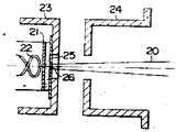
전자총은 제1도와 같이 열음극(21), 이이티(22), 그리드(23), 에노우드(24) 및 그리드(23)와 전기적으로 접속되고 계구(26)를 갖는 디스크(25)를 포함한다.The electron gun includes, as in FIG. 1, a disk 25 having a
상술한 전자총에서는 그리드(23)(디스크(25)포함)및 애노우드(24)는 캐소우드 전위에 대해서 정(正) 전위가인가된다.In the electron gun described above, the positive potential is applied to the grid 23 (including the disk 25) and the
이와같은 전자총은 2극형 전자총이라고 도불리워지고 2극관과 같은 동작을 한다.Such electron guns are also called bipolar guns and behave like dipoles.
특히 이전자총에 있어서는 열음극(21)과 그리드(23)간에 형성된 전자 렌즈가 없으므로 열음극(21)으로 부터 방사된 전자비임은 아무런 크로소오더(crossover)도 발생 하지않게 하고 그리고 전자비임의 직경을 그리드(23)에 형성된 개구(26)에 의하여 그 직경을 제한하여 작은 직경을 갖는 전자비임(20)을 발생시킨다.In particular, in the former magnet gun, since there is no electron lens formed between the
또 제2도와 같이 열음극(21)측면의 개구(26)의 연부는 반대측 연부보다 직경이작다. 즉 개구(26)는 개구의 측벽에 의해 산란되는 전자로 인한 전자 비임의 직경의 증대를 방지 하기 위해 나이프에지(knife edge)로 형성된다.Moreover, as shown in FIG. 2, the edge of the
그러나, 제2도에 나타낸 바와같은 이상적인 형상을 갖는 개구를 만들기는 매우 어렵다. 또 열음극으로부터 방출된 전자비임은 전자총의 축(軸)에 수직 방향 즉 반경 방향의 속도 성분을 가지는 전자도 포함되어 있으므로 계구의 내역에서 생기는 산란전자를 충분히 억제할 수가 없다.However, it is very difficult to make an opening having an ideal shape as shown in FIG. The electron beam emitted from the hot cathode also contains electrons having a velocity component in a direction perpendicular to the axis of the electron gun, i.e., the scattered electrons generated in the details of the system cannot be sufficiently suppressed.
그러므로 제1도와 같은 구성에 의한 전자총을 사용한 텔리비젼 촬상관에 있어서는 이와같은 산란 전자에 의하여 특히 화면 주변부로 편양된 전자 비임의 스포트직경이 증대하기 때문에 화면주변부의 해상도가 현저히 열화된다.Therefore, in the television imaging tube using the electron gun according to the configuration as shown in FIG. 1, the resolution of the peripheral portion of the screen is significantly degraded because the spot diameter of the electron beam, which is especially arranged around the screen by the scattering electrons, increases.
또한 일본특허출원 특개소79-129871호(영국 특허출원 특개소번호 GB 2015817 A 및 1978.2.13 출원된 대응 미국 출원번호 제877080호와 동일)의 전자총은 상기 2극형전자총을 응용한 것으로서 그리드 및 애노우드간에 음극의 전자방사에 거의 영향을 주지 않는 전자 접속렌즈를 형성하여 전자 비임을 약간 크로소오버 시키도록 구성안 전자총이 제한되고 있다.In addition, the electron gun of Japanese Patent Application Laid-Open No. 79-129871 (equivalent to British Patent Application No. GB 2015817 A and the corresponding US Application No. 877080 filed on February 2, 1978) is an application of the two-pole type electron gun. The electron gun has been limited to form an electron connecting lens that hardly affects the electron emission of the cathode between the woods so that the electron beam is slightly cross-over.
이 전자총은 제3도에 나타낸 바와 같이 제일 계구(26)를 갖는 그리드(23)(즉, 제1애노우드)및 제2계구(28)를 갖는 애노우드(24)(즉, 제2애노우드)를 포함한다. 애노우드(24)는 제 2 개구(28)를 갖는 디스크(27)로 부분적으로 닫혀있다. 제1개구(26)의 직경은 적어도 제2개구(28)의 직경의 2배로 크며 제1개구(26)의 직경은 적절하게 작게 형성한다.This electron gun has an anode 24 (i.e., second anode) having a grid 23 (i.e. first anode) and a
이 전자총에 있어서는 그리드(23)에는 10 내지 수 10볼트의 정(+)전압을 인가하고, 또한 그리드에 공급되는 전압의 적어도 10배 즉 적어도 100볼트의 정전압을 애노우드(24)에 인가하여, 그리드 전극 및 애노우드 전극간에 캐소우드의 전자 방사에 거의 영향을 주지 않는 렌즈 전계를 형성하므로서 그리드(23)에서의 제1계구를 통과한 전자비임을 크로스 오버시킨다.In this electron gun, a positive voltage of 10 to several 10 volts is applied to the
그러므로 약 0.05mm 정도의 직경을 갖는 제2계구(28)에 의하여 통과된 비임 전류와 발산 비임 각을 제어하여 작은 직경을 갖는 전자 비임(20)을 발생시킨다.Therefore, the beam current and the diverging beam angle passed by the
상술한 전자총에서는 크로스 오버를 형성하기 위하여 발생되는 전자비임을 포함하는 전자군(群)은 캐소우드 온도에 의해 결정되는 에너지 분포폭보다 넓은 에너지 분포폭을 가지므로 용량성 잔상이 크다.In the electron gun described above, the electron group including the electron beam generated to form the crossover has a larger energy distribution width than the energy distribution width determined by the cathode temperature, and thus has a large capacitive afterimage.
본 발명의 목적은 상술한 결점을 모두 제거하기 위한 것으로서 전자총축 방향의 균등한 에너지 분포를 갖는 전자 비임을 발생시켜 비디콘(vidicon)형 텔리비젼 촬상관에 사용할 경우 애상도 가높고 균등하며 지연(즉, 잔상(殘像)은 작은 2극영 전자총을 제공하는데에 목적이 있다.An object of the present invention is to eliminate all the above-mentioned drawbacks, and generates an electron beam having an even energy distribution in the electron axis direction, so that when used in a vidicon type television camera, the image quality is high, even and delayed (that is, The afterimage aims to provide a small bipolar gun.
본 발명은 상기 목적 및 또 다른 목적을 달성하기 위해서 전자 비임을 방출하기 위한 열음극과 전자 비임의 직경을 제어하기 위한 제 1 개구를 갖는 그리드, 제 1 개구를 통과한 전자비임의 일부를 포획하기 위한 제개구를 갖는 애노우드로 구성하고, 제 2 개구의 직경보다 작거나 같게 한다. 제 1 개구의 직경을 예를들면 그리드 및 애노우드 간에 균등한 관측방향의 전계를 형성하기 위하여 그리드 및 애노우드에는 캐소우드 전위보다 정(+)인 즉 5볼트~수 10볼트 및 100~500볼트를 각각 인가한다.The present invention provides a grid having a hot cathode for emitting an electron beam, a grid having a first opening for controlling the diameter of the electron beam, and a portion of the electron beam passing through the first opening in order to achieve the above object and another object. It consists of an anode having an opening and is smaller than or equal to the diameter of the second opening. The diameter of the first opening, for example, 5 volts to 10 volts and 100 to 500 volts in the grid and the anode, which is positive (+) than the cathode potential, to form an electric field in an even direction of observation between the grid and the anode. Apply each.
이와 같이 그리드와 애노우드간에 일정한 도측 전계는 정전류(定電流)밀도를 갖는 층류전자비임을 발생시킨다.As such, the constant field between the grid and the anode generates a laminar electron beam with a constant current density.
상기 구조의 전자총에 있어서는 캐소우드로 부터 방사된 전자비임은, 그리드의 제 1 개구에 의해 그 직경이 제한되어 추출된다. 제 1 개구를 통과한 전자비임에는 제 1개구에서 발생된 산란전자와 캐소우드로부터 방출된 반경 방향의 속도 성분이 큰 전자가 포함된다.In the electron gun of the above structure, the electron beam radiated from the cathode is extracted with its diameter limited by the first opening of the grid. The electron beam passing through the first opening includes scattered electrons generated at the first opening and electrons having a large radial velocity component emitted from the cathode.
그러나 이들 전자는 애노우드에 설치된 제 2개구에 의하여 포획되므로 반경 방향의 작은 속도 성분을 갖는 전자만이 제 2 개구를 통과하게 된다.However, these electrons are captured by the second opening provided in the anode so that only electrons with small radial velocity components pass through the second opening.
또 본 발명의 2극형 전자총에서는 전자총에 의해 발생된 전자 비임내의 전자는 캐소우드로부터 전자비임이 크로스 오버를 형성하지 않기 때문에 전자총에서 발생한 축방향으로의 속도 분포폭은 캐소우도 온도에 의해 정해진 속도 분포폭과 실제로 동일한 폭을 가진다.In the bipolar electron gun of the present invention, since the electrons in the electron beam generated by the electron gun do not form a crossover from the cathode, the velocity distribution width in the axial direction generated by the electron gun is determined by the cathode temperature. It is actually the same width as the distribution width.
그 결과, 이와같은 2극형 전자종이 사용된 텔리비젼 촬상관에서는 전자 비임의 스포트의 크기는 일정하게 유지된다. 따라서 상술한 촬상관은 종래의 2극형 전자총으로된 텔레비젼 촬상관에 비해분해도가 높고 균일한 해상도와 잔상이 얻어진다.As a result, the spot size of the electron beam is kept constant in the television imaging tube in which such a bipolar electron species is used. Therefore, the imaging tube described above has a higher resolution than the conventional television imaging tube made of a two-pole electron gun, and a uniform resolution and afterimage are obtained.
이하 본 발명의 실시예를 도면에 따라 설명한다.Hereinafter, embodiments of the present invention will be described with reference to the drawings.
제4도는 본 발명에 의한 전자총의 일 실시예를 나타낸 단면도이다. 제4도에 있어서 우측에 폐쇄단부(32)를 갖는 원통형 슬리이브(31) 및 원통형 슬리이브(31)내에 설치된 이이티(33)를 포함하는 열음극(30)으로 구성된다. 폐쇄단부(32)는 전자 방출 물질로 만들어진 펠렛(pellet)을 가지며, 평행상의 캐소우드 표면을 형성한다.4 is a cross-sectional view showing an embodiment of an electron gun according to the present invention. In FIG. 4, it consists of the
이이터(33)는 열음극의 펠렛으로 부터 전자를 방출하는데 필요한 열을 발생한다.The
그리드(40) 및 애노우드(50)는 제4도에 나타낸 바와 같이 서로 일정한 간격으로 분리시켜 캐소우드(30)의 한쪽방향으로 배열되어 있다.The
그리드(40)는 컵 형상의 전극(41)과 원판(45)으로 구성된다. 컵형상의 전극(4)은 캐소우드 표면에 근접되고 대략 평행으로 위치한 평판부(42)와 원통형 슬리브(31)와 동심적으로 배열된 원통부(43)를 갖는다. 원통부(43)는 슬리이브(31)보다 내경이 크며 열음극(30)방향으로 뻗어 있다. 평판부(42)는 중심부에 올(44)이 있으며, 그 직경은 올(44)에 인접하는 슬리브(31)의 직경보다 작다. 디스크(45)는 평판부(42)에 형성된 올(44)의 직경보다 큰 직경을 가지며 원통부(43)의 내경보다는 작다. 디스크(45)는 음극면 가까운 쪽에 배치된 평판부(42)의 표면상에 있는 올(44)과 동심적으로 설치되어 있으며 컵모양의 전극(41)과 전기적으로 접촉되어 있다. 디스크(45)는 비자성물질로 만들어져 있으며 평판부(42)보다 두께가 얇다. 디스크(45)는 그 중심부(46)을 이있으며 올(46)은 평판부(42)의 올(44)과 동심적으로 배열되어 있으며 올(44)보다 직경이 훨씬 작다. 올(46)의 직경은 경사진 올을 얻기위해서 캐소우드 표면 가까운 곳에서 가장 작고 캐소우드 표면에서 멀어질수록 크게 한다. 컵영상의 전극(41)의 올(44)은 경사진 올(46)을 갖는 디스크(45)로 부분적으로 덮어지게 된다. 이 올(49)은 그리드(40)에 있어서의 제1개구를 형성한다. 또한 애노우드(50)는 컵영상의 전극(51)과 디스크(56)로 구성된다. 이 컵형상의 전극(51)은 평판부(42)에 근접하여 대략 평행으로된 평판부(52)와 그리드(40)의 원통부(43)와 동심적으로 대략 동일한 내경을 가지며, 캐소우드(30)와 반대 방향으로 뻗어 있는 원통부(53)와 캐소우드(30)와 반대 방향에 립(lip)부(52)로 형성되어 있다.The
평판부(55)는 그 중심부에 올(40)이 있으며, 그 직경은 그리드(44)에 있는 올(44)의 직경과 거의 동일하며, 그 중심축은 전자총의 축과 일치한다(제4도 참조).The plate portion 55 has an oval 40 at its center, the diameter of which is approximately equal to the diameter of the oar 44 in the grid 44, the central axis of which corresponds to the axis of the electron gun (see FIG. 4). ).
니스크(56)는 그 직경이 평판부(52)의 올(55)의 직경보다 크더 원통부(53)의 내경보다는 작다.The
이 디스크(56)는 올(55)과 동심적으로 설치되고 평판부(52)의 캐소우드(30)로 부터 멀리 떨어져 있는 면쪽에 배치되고, 컵영상의 전극(51)과 전기적으로 접속되어 있다.The
그러므로 평판부(52)의 올(55)은 디스크(56)에 의해 덮혀있다. 디스크(45)와 같이 디스크(56)는 비자성물질 만들어져 있으며, 평판부(52)보다 두께가 얇다.Therefore, the ol 55 of the flat plate portion 52 is covered by the
디스크(56)는 그 중심부에 평판부(52)의 올(55)보 다는 직경이 훨씬 작고 인접한 그리드(40)의 제 1 계구(46)의 직경이 상이되는 올(57)이 형성되어어 있다. 이 올(57)은 애노우드(50)에 있어서 제 2 개구를 형성한다.The
상술한 구조를 갖는 본 발명의 실시예에 있어서는 그리드(40)에는 캐소우드 전위에 대해서 정전위 예를들면 5~50볼트의 전압을 인가하고 에노우드 전극(50)에는 그리드(40)및 애노우드(50)간에 균일한 축방향의 전계를 형성 하기 위하여 즉 대략 일정한 전류 밀도를 갖는 층류 전자 비임을 형성하기 위하여 캐소우드 전위에 대해서 또 다른 정전위, 예를들면 100~500볼트의 전압을 인가한다.In the embodiment of the present invention having the structure described above, the
본(발명을 좀 더 상세히 설명하기 위해서 한쌍의 평행인 평판 전극을 갖는 2극관이 제한된 공간 전하 영역에서 동작하는 경우를 알아본다.To describe the invention in more detail, we will look at a case where a bipolar tube with a pair of parallel plate electrodes operates in a limited space charge region.
캐소우드와 애노우드 간의 거리와 캐소우드 전위에 대한 애노우드 전위를 각각 X 및 E로 표시하면 애노우드전류 밀도 J는 다음 방정식으로 주어진다.If the distance between the cathode and the anode and the anode potential for the cathode potential are represented by X and E, respectively, the anode current density J is given by the following equation.
(child-Langmuir 방정식)(child-Langmuir equation)

식(Ⅰ)은 3/2승 법칙(three-halves power low)이라고 한다. 애노우드 전류가 일정하게 유지되는 데에 대해서는 다음 공식이 성립하다.Equation (I) is called the three-halves power low. The following formula holds for the constant anode current.

제4도에 나타낸 실시예에서 층류 전자비임이 형성되면 전류밀도 J는 일정하게 유지된다.In the embodiment shown in FIG. 4, when the laminar electron beam is formed, the current density J is kept constant.
제5도에서 캐소우드(30), 그리고(40) 및 애노우드(50)에 각각 0볼트, Ec1 볼트 및 Ec2 볼트의 전위가 인가될 경우 각 상태에서 전류밀도 J는 일정하게 유지되어, 캐소우드(30)와 그리고(40)의 홀(46)간의 거리(제4도에서 캐소우드 단부(32)와 그리드(40)의 디스크(45)간의 거리에 대응)와 그리드(40)의 홀(제 1 개구)(46)와 에노우드(50)의 제 2 홀(57)간의 거리(제 4 도에서 그리드(40)의 디스크(45)와 애노우드(50)의 디스크(56)간의 거리에 대응)는 각각 및 L로 표시하던 식(Ⅱ)로부터 다음 공식이 구해진다.In FIG. 5, when the potentials of 0 volts, Ec1 volts, and Ec2 volts are applied to the

따라서, 본 발명에서는 전위 Ec1 및 Ec2와 거리 ι및 L을 설정하므로서 상술한 공식(Ⅲ)을 만족시킬 수 있다.Therefore, in the present invention, the above formula (III) can be satisfied by setting the potentials Ec1 and Ec2 and the distances? And L.
다음에 본 발명에 관한 전자총의 여러가지 예를 종래의 전자 총과 비교하여 설명한다.Next, various examples of the electron gun according to the present invention will be described in comparison with the conventional electron gun.
제5도는 제4도에 나타낸 실시예의 주요부의 확대 단면도이고, 부호 T는 그리드(40)의 평판부(42)의 두께, D1은 홀(44)의 직경, t는 디스크(45)의 두께, d1은 캐소우드 측면상의 홀(즉, 제1개구)의 직경, D2는 애노우드(50)의 평판부(52)에 형성된 홀(55)의 직경, d2는 디스크(56)에 형성된 홀 (57) (즉, 제2개구)의 직경을 나타낸다.5 is an enlarged cross-sectional view of the main part of the embodiment shown in FIG. 4, where T is the thickness of the
평판부(52)의 두께 및 디스크(56)의 두께는 각각 평판부의 두께. 및 디스크(45)의 두께 t와 대략 동일하게 만들어진다. 다음 표 1은 본발명에 관한 전자총의 예 ①,②,③,④ 및 ⑤와 종래예의 전자총의 치수와 특성을 함꼐 나타낸 것이다. 좀더 상세히 설명하던, 수치는 거리 ι및 L, 직경 d1및d2그리고 비를 나타내고 특성은 비임전류 iA, 중심에서의 진폭변조도 ARce 및 해상도균일성 ARcc/ARce를 포함한다.The thickness of the flat plate portion 52 and the thickness of the
[표 1]TABLE 1

표1에 나타낸 기타의 치수를 고려하면 매개변수 T, D1 및 D2는 종래의 예와 실시예 ①,②,③ 및 ④에 있어서는 각각 0.03mm, 0.18mm, 0.9mm 및 0.9mm로 하고 실시예 ⑤에 있어서는 각각 0.03mm, 0.12mm, 0.65mm 및 0.65mm로 하였다.Considering the other dimensions shown in Table 1, the parameters T, D1 and D2 are 0.03 mm, 0.18 mm, 0.9 mm and 0.9 mm in the conventional examples and Examples ①, ②, ③ and ④, respectively. In the case of 0.03 mm, 0.12 mm, 0.65 mm and 0.65 mm, respectively.
또한 동작전위에 관해서는 캐소우드 전위, 그리드 전위 Dc1 및 애노우드 전위 Ec2는 종래의 예와 실시예 1,2,3,4 및 5 모두에 대해 층류전자비임을 형성하기 위하여 각각 0V, 5~30V 및 150~3000V로 하였다.In terms of the operating potential, the cathode potential, the grid potential Dc1, and the anode potential Ec2 are 0 V, 5 to 30 V, respectively, to form a laminar electron beam for the conventional examples and Examples 1, 2, 3, 4, and 5, respectively. And 150 to 3000 V.
본 발명에 의해 얻어지는 특성 및 효과에 관하여 표1을 참고로 하여 설명하다.The characteristics and effects obtained by the present invention will be described with reference to Table 1.
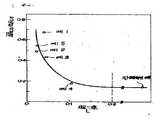
먼저 비임전류(iA)와 중심에서의 진폭 변조도 ARce를 설명하다. 여기서 비임전류 iA는 캐소드전류밀리가 1A/㎠일때 그리드(40)의 제 1 개구(46)를 통과하는 전류로 정의한다. 그리고 중심 진폭변조도 ARce는 일반적으로 해상도와 대응한다. 제6도는 홍측에 제 1 개구(46)의 직경 d1과 종축에 중심 진폭 변조도 ARce로 하여 표1의 값을 프롯트 한 것이다.First, the beam current iA and amplitude modulation at the center ARce will be described. Here, the beam current iA is defined as the current passing through the first opening 46 of the
제6도에서 흑점은 비임전류 iA, ⊙점은 중심 진폭 변조도 ARce를 나타낸다.In FIG. 6, the black spot represents the beam current iA and the ⊙ point represents the center amplitude modulation degree ARce.
제6도에서 모든 바와 같이 비임전류 iA는 제 1 개구의 직경 d1에 비례하여 직선적으로 증가하나 중심진폭변조도 ARce는 직경 d1에 비례하여 감소한다.As shown in Fig. 6, the beam current iA increases linearly in proportion to the diameter d1 of the first opening, but the central amplitude modulation ARce decreases in proportion to the diameter d1.
정상적인 비디콘형 촬상관을 동작시키기 위해서는 수 10마이크로암페어(microamperes)의 비임 전류가 필요하다.In order to operate a normal non-icon type imager, a beam current of several ten microamperes is required.
따라서 제 1 개구(홀)의 직경 d1을 크게하는 것이 바람직하다. 그러나 비임전류를 증가시키기 위하여 제1개구의 직경 d1을 크게하면 중심 진폭 변조도 ARce는저하하여 충분한 해상도를 얻기가 불가능해진다.Therefore, it is preferable to enlarge the diameter d1 of a 1st opening (hole). However, if the diameter d1 of the first opening is increased in order to increase the beam current, the center amplitude modulation degree ARce is lowered and it is impossible to obtain sufficient resolution.
반면에 전류밀도를 크게하여 비임전류를 증가시킬 수가 있다. 그러나 열음극은 제한된 전자방출능력에 한개가 있다(즉, 제한전류밀도)캐소우드가 안정된 전자 방출을 수행하기 위한 전류밀도는 산화물 캐소우드에 있어서는 대략 0.5A/㎠보다 작고, 함침형 캐소우드에 있어서는 약 2A/㎠보다 작다.On the other hand, the beam current can be increased by increasing the current density. However, the hot cathode has only one limited electron emission capability (ie, limited current density). The current density for the cathode to achieve stable electron emission is less than approximately 0.5 A /
따라서 적당한 범위는 제 1 개구의 직경 d1에 따라 정해진다.The suitable range is therefore determined according to the diameter d1 of the first opening.
본 발명에 있어서는 직경 d1이 0.01mm≤d1≤0.05mm의 관계를 갖는 값을 가질 경우에 촬상관을 동작하기에 필요한 비임전류가 형성되고 또한 충분한 해상도가 얻어진다.In the present invention, when the diameter d1 has a value having a relationship of 0.01 mm? D1? 0.05 mm, a beam current necessary for operating the image pickup tube is formed, and sufficient resolution is obtained.
다음에 해상도 균일성 ARco/ARce를 설명한다. 해상도 균일성 ARco/ARce은 주사영역 중심에서의 진폭변조도(즉, 해상도) ARce 대주사영역 주변부에서의 진폭변조도(즉, 해상도) ARco의 비이다.Next, the resolution uniformity ARco / ARce will be described. Resolution Uniformity ARco / ARce is the ratio of amplitude modulation (i.e. resolution) ARco at the center of the scanning area to amplitude modulation (i.e., resolution) ARco around the periphery of the scanning area.
텔리비젼 촬상관의 해상도는 광도전 타게트에 투사되는 전자비임의 스포트(Spot) 크기와 밀접한 관계가 있으며 스포트 크기가 작을수록 해상도가 높아진다.The resolution of the television imaging tube is closely related to the spot size of the electron beam projected onto the photoconductive target. The smaller the spot size, the higher the resolution.
그러나 접속된 전자비임의 실현 가능한 최소직경은 전자의 열분산속도, 공간전하요과 및 집속계의 구면수차(水差)에 의해 정해진다.However, the minimum feasible diameter of the connected electron beam is determined by the heat dissipation rate of the electrons, the space charge fluctuations, and the spherical aberration of the focusing system.
텔리비젼 촬상관에서는 비임전류가 작으므로 주사영역 중앙부에서의 스포트 직경 Doe은 주로 전자의 열방사속도 및 구면수차에 의해 정해진다.In the television imaging tube, since the beam current is small, the spot diameter Doe at the center of the scanning region is mainly determined by the thermal radiation rate and spherical aberration of the electron.
또 전자총으로 부터의 전자 비임의 발산각이 작기 때문에 열속도 분산효과는 크고 이것을 실질적으로 주사영역 중앙부에서의 스포트 직경 Doe를 결정한다.In addition, since the divergence angle of the electron beam from the electron gun is small, the thermal velocity dissipation effect is large and this substantially determines the spot diameter Doe at the center of the scanning region.
열속도 분산에 의하여 생기는 스포트 직경 DL은 다음의 Lagmuir 방정식으로부터 구해진다.The spot diameter DL caused by thermal velocity dispersion is obtained from the following Lagmuir equation.

여기서 ρc는 캐소우드에서의 전류밀도, Tk는 캐소우드 온도, ρ는 접속점에의 비임접속각(이것은 텔리비젼 촬상관에서는 렌즈 계의 각도 배율은 거의 1과 같기 때문에 전자총 출구에서의 비임발산각과 거의 같다). V는 접속점에서의 전위, iB는 비임전류, k는 볼쯔만(Boltzmann)상수 그리고 k는 전자의 전하량을 표시한다. 식(Ⅳ)으로 부터 알 수 있는 같와 같이 중심부에서의 스포트 직경 Dce는 실질적으로 전자총 출구에서의 비임발산 각에 반비례한다.Where ρc is the current density at the cathode, Tk is the cathode temperature, and ρ is the beam connection angle to the junction (this is almost the same as the beam emission angle at the exit of the electron gun since the angle magnification of the lens system is nearly equal to 1 in a television imaging tube). . V is the potential at the junction, iB is the beam current, k is the Boltzmann constant, and k is the charge of the electron. As can be seen from Equation (IV), the spot diameter Dce at the center is substantially inversely proportional to the beam divergence angle at the exit of the electron gun.
반면에 주사영역 주변부에서의 스포트 직경 Dco는 편양계 편향수차로 인하여 중심부에서의 스포트 직경 Dce 보다크다. 편향 수차는 전자총 충구에서의 비임 발산각(또는 비임 발산 각의 제곱)에 비례해서 직선으로 증가하는 경향이 있다.On the other hand, the spot diameter Dco at the periphery of the scanning area is larger than the spot diameter Dce at the center due to the deflection aberration of the bias system. The deflection aberration tends to increase linearly in proportion to the beam divergence angle (or the square of the beam divergence angle) in the electron gun charging.
따라서 주변부에서의 스포트 직경 대주사영역 중심부에서의 스포트 직경의 비는 전자총 출구에서의 비임발산 각에 비례하여 증가한다.Therefore, the ratio of the spot diameter at the periphery to the spot diameter at the center of the scanning region increases in proportion to the beam divergence angle at the exit of the electron gun.

비임 발산각은 전자총의 특성이 된다.The beam divergence angle is characteristic of the electron gun.
그러나 그리드에서 발생한 산란전자를 고려하면 그리드의 제 1 개구의 직경 d1, 애노우드의 제2개구의 직경 및 d2 제1, 제2 개구간의 거리 L에 의해 결정되는 비임발산 각은 각도 tan_1,

실제로 진폭변조도(즉, 해상도)는 스포트 직경에 반비례 하기 때문에 해상도 균일성

그리고 해상도 균일성은 파라미터
표1의 값을 제7도의 홍축에 파라미터

제7도에 나타낸 바와 같이 해상도 균일성은 파라미터
따라서 높은 해상도 균일성을 얻기 위해서는 예를들면 전자총의 파라미터
종래의 예보다 높은 해상도 균일성을 얻기 위해서 예를들면 전자총의 파라미터


따라서 종래예와 비교하여 높은 해상도 균일성을 얻기 위해 본 발명의 전자총의 파라미터

이상 설명한 바와 같이, 본 발명에 의하던 촬상관을 작동 시키는데 필요한 비임 전류를 발생할 수 있고 주사영역 주변부에서 진폭변조도(즉, 해상도)를 개선할 수 있고, 주사영역 전면에 걸쳐 해상도 균일성을 현저히 향상시킬 수 있으며, 또 크로스 오버가 없는 충류전 자비임을 형성하여 지연(즉, 잔상)을 작게하는, 텔리비젼 촬상관용 전자총을 제공할 수가 있다.As described above, the beam current required to operate the imaging tube according to the present invention can be generated, the amplitude modulation degree (i.e., resolution) can be improved at the periphery of the scanning area, and the resolution uniformity is significantly improved over the entire scanning area. In addition, it is possible to provide an electron gun for a television imaging tube, which forms a charge-discharge zyme with no crossover, thereby reducing delay (i.e., afterimage).
Claims (4)
Translated fromKoreanApplications Claiming Priority (3)
| Application Number | Priority Date | Filing Date | Title |
|---|---|---|---|
| JP55-150649 | 1980-10-29 | ||
| JP55150649AJPS5774948A (en) | 1980-10-29 | 1980-10-29 | Electron gun |
| JP150649 | 1990-06-08 |
Publications (2)
| Publication Number | Publication Date |
|---|---|
| KR830008382A KR830008382A (en) | 1983-11-18 |
| KR860001678B1true KR860001678B1 (en) | 1986-10-16 |
Family
ID=15501453
Family Applications (1)
| Application Number | Title | Priority Date | Filing Date |
|---|---|---|---|
| KR1019810004139AExpiredKR860001678B1 (en) | 1980-10-29 | 1981-10-28 | A electron gun |
Country Status (4)
| Country | Link |
|---|---|
| US (1) | US4467243A (en) |
| JP (1) | JPS5774948A (en) |
| KR (1) | KR860001678B1 (en) |
| DE (1) | DE3142777C2 (en) |
Families Citing this family (10)
| Publication number | Priority date | Publication date | Assignee | Title |
|---|---|---|---|---|
| US4549113A (en)* | 1981-02-06 | 1985-10-22 | U.S. Philips Corporation | Low noise electron gun |
| US4695773A (en)* | 1981-12-18 | 1987-09-22 | The Perkin-Elmer Corporation | Field emission gun electrode geometry for improved focus stability |
| NL8200253A (en)* | 1982-01-25 | 1983-08-16 | Philips Nv | TELEVISION ROOM TUBE. |
| JPS6129045A (en)* | 1984-07-18 | 1986-02-08 | Hitachi Ltd | Image tube device |
| NL8700834A (en)* | 1987-04-09 | 1988-11-01 | Philips Nv | DIODE GUN WITH COMPOSITE ANODE. |
| US5223764A (en)* | 1991-12-09 | 1993-06-29 | Chunghwa Picture Tubes, Ltd. | Electron gun with low voltage limiting aperture main lens |
| US5220239A (en)* | 1991-12-09 | 1993-06-15 | Chunghwa Picture Tubes, Ltd. | High density electron beam generated by low voltage limiting aperture gun |
| US5159240A (en)* | 1991-12-09 | 1992-10-27 | Chunghwa Picture Tubes, Ltd. | Low voltage limiting aperture electron gun |
| US5182492A (en)* | 1992-05-20 | 1993-01-26 | Chunghwa Picture Tubes, Ltd. | Electron beam shaping aperture in low voltage, field-free region of electron gun |
| JP2002083559A (en)* | 2000-06-26 | 2002-03-22 | Sony Corp | Electron gun, cathode-ray tube, and image display device |
Family Cites Families (8)
| Publication number | Priority date | Publication date | Assignee | Title |
|---|---|---|---|---|
| US2173165A (en)* | 1936-05-16 | 1939-09-19 | Rca Corp | Electron tube |
| US3045141A (en)* | 1957-04-15 | 1962-07-17 | Rca Corp | Electron beam tube |
| US3374379A (en)* | 1964-03-02 | 1968-03-19 | Nippon Columbia | Low second grid voltage electron gun |
| GB1145205A (en)* | 1966-06-17 | 1969-03-12 | English Electric Valve Co Ltd | Improvements in or relating to cathode ray tubes |
| US3873878A (en)* | 1970-07-31 | 1975-03-25 | Tektronix Inc | Electron gun with auxilliary anode nearer to grid than to normal anode |
| US3928784A (en)* | 1971-07-02 | 1975-12-23 | Philips Corp | Television camera tube with control diaphragm |
| US3894261A (en)* | 1973-07-09 | 1975-07-08 | Hughes Aircraft Co | No-crossover electron gun |
| JPS54129871A (en) | 1978-02-13 | 1979-10-08 | Philips Nv | Device having camera tube |
- 1980
- 1980-10-29JPJP55150649Apatent/JPS5774948A/enactiveGranted
- 1981
- 1981-10-28KRKR1019810004139Apatent/KR860001678B1/ennot_activeExpired
- 1981-10-28DEDE3142777Apatent/DE3142777C2/ennot_activeExpired
- 1981-10-28USUS06/315,869patent/US4467243A/ennot_activeExpired - Lifetime
Also Published As
| Publication number | Publication date |
|---|---|
| US4467243A (en) | 1984-08-21 |
| KR830008382A (en) | 1983-11-18 |
| DE3142777C2 (en) | 1987-05-07 |
| JPS5774948A (en) | 1982-05-11 |
| DE3142777A1 (en) | 1982-07-08 |
| JPH0211972B2 (en) | 1990-03-16 |
Similar Documents
| Publication | Publication Date | Title |
|---|---|---|
| KR860001678B1 (en) | A electron gun | |
| US2971118A (en) | Electron discharge device | |
| US4168452A (en) | Tetrode section for a unitized, three-beam electron gun having an extended field main focus lens | |
| US3894261A (en) | No-crossover electron gun | |
| US2852716A (en) | Cathode ray tube and electron gun therefor | |
| RU2095878C1 (en) | Electron gun of color cathode-ray tube (options) | |
| CA1135774A (en) | Cathode-ray tube with low anode potential preventing positive ion formation | |
| US3327160A (en) | Electrostatic electron optical system | |
| US3377492A (en) | Flood gun for storage tubes having a dome-shaped cathode and dome-shaped grid electrodes | |
| CA1212983A (en) | Low noise electron gun | |
| US4540916A (en) | Electron gun for television camera tube | |
| US3213311A (en) | Electron discharge device | |
| CA1173485A (en) | Anode shape of the diode electron gun in television camera tube | |
| US4334170A (en) | Means and method for providing optimum resolution of T.V. cathode ray tube electron guns | |
| US3139552A (en) | Charged particle gun with nonspherical emissive surface | |
| EP0570541B1 (en) | Low voltage limiting aperture electron gun | |
| US5220239A (en) | High density electron beam generated by low voltage limiting aperture gun | |
| US6522057B1 (en) | Electron gun for cathode ray tube | |
| US3307061A (en) | Electrostatic return beam camera tube | |
| US4496877A (en) | Unipotential electron gun for short cathode ray tubes | |
| US2672568A (en) | Electron gun for cathode-ray tubes | |
| KR100349901B1 (en) | Electron gun for colored cathode ray tube | |
| KR920010660B1 (en) | Electron gun for color cathode ray tube | |
| US4173727A (en) | Electron image device | |
| US4942334A (en) | Electron-gun system |
Legal Events
| Date | Code | Title | Description |
|---|---|---|---|
| PA0109 | Patent application | St.27 status event code:A-0-1-A10-A12-nap-PA0109 | |
| PA0201 | Request for examination | St.27 status event code:A-1-2-D10-D11-exm-PA0201 | |
| P11-X000 | Amendment of application requested | St.27 status event code:A-2-2-P10-P11-nap-X000 | |
| P13-X000 | Application amended | St.27 status event code:A-2-2-P10-P13-nap-X000 | |
| PG1501 | Laying open of application | St.27 status event code:A-1-1-Q10-Q12-nap-PG1501 | |
| PE0902 | Notice of grounds for rejection | St.27 status event code:A-1-2-D10-D21-exm-PE0902 | |
| T11-X000 | Administrative time limit extension requested | St.27 status event code:U-3-3-T10-T11-oth-X000 | |
| P11-X000 | Amendment of application requested | St.27 status event code:A-2-2-P10-P11-nap-X000 | |
| P13-X000 | Application amended | St.27 status event code:A-2-2-P10-P13-nap-X000 | |
| PG1605 | Publication of application before grant of patent | St.27 status event code:A-2-2-Q10-Q13-nap-PG1605 | |
| PE0701 | Decision of registration | St.27 status event code:A-1-2-D10-D22-exm-PE0701 | |
| PR0701 | Registration of establishment | St.27 status event code:A-2-4-F10-F11-exm-PR0701 | |
| PR1002 | Payment of registration fee | St.27 status event code:A-2-2-U10-U11-oth-PR1002 Fee payment year number:1 | |
| PR1001 | Payment of annual fee | St.27 status event code:A-4-4-U10-U11-oth-PR1001 Fee payment year number:4 | |
| PR1001 | Payment of annual fee | St.27 status event code:A-4-4-U10-U11-oth-PR1001 Fee payment year number:5 | |
| PR1001 | Payment of annual fee | St.27 status event code:A-4-4-U10-U11-oth-PR1001 Fee payment year number:6 | |
| PR1001 | Payment of annual fee | St.27 status event code:A-4-4-U10-U11-oth-PR1001 Fee payment year number:7 | |
| PR1001 | Payment of annual fee | St.27 status event code:A-4-4-U10-U11-oth-PR1001 Fee payment year number:8 | |
| PR1001 | Payment of annual fee | St.27 status event code:A-4-4-U10-U11-oth-PR1001 Fee payment year number:9 | |
| PR1001 | Payment of annual fee | St.27 status event code:A-4-4-U10-U11-oth-PR1001 Fee payment year number:10 | |
| PC1903 | Unpaid annual fee | St.27 status event code:A-4-4-U10-U13-oth-PC1903 Not in force date:19961017 Payment event data comment text:Termination Category : DEFAULT_OF_REGISTRATION_FEE | |
| PC1903 | Unpaid annual fee | St.27 status event code:N-4-6-H10-H13-oth-PC1903 Ip right cessation event data comment text:Termination Category : DEFAULT_OF_REGISTRATION_FEE Not in force date:19961017 | |
| R18-X000 | Changes to party contact information recorded | St.27 status event code:A-5-5-R10-R18-oth-X000 | |
| PN2301 | Change of applicant | St.27 status event code:A-5-5-R10-R13-asn-PN2301 St.27 status event code:A-5-5-R10-R11-asn-PN2301 | |
| R18-X000 | Changes to party contact information recorded | St.27 status event code:A-5-5-R10-R18-oth-X000 | |
| R18-X000 | Changes to party contact information recorded | St.27 status event code:A-5-5-R10-R18-oth-X000 |