KR800000140B1 - Method of neasuring automatically successive sections of an elongated material - Google Patents
Method of neasuring automatically successive sections of an elongated materialDownload PDFInfo
- Publication number
- KR800000140B1 KR800000140B1KR7301085AKR730001085AKR800000140B1KR 800000140 B1KR800000140 B1KR 800000140B1KR 7301085 AKR7301085 AKR 7301085AKR 730001085 AKR730001085 AKR 730001085AKR 800000140 B1KR800000140 B1KR 800000140B1
- Authority
- KR
- South Korea
- Prior art keywords
- pulse
- echo
- signal
- input
- jacket
- Prior art date
- Legal status (The legal status is an assumption and is not a legal conclusion. Google has not performed a legal analysis and makes no representation as to the accuracy of the status listed.)
- Expired
Links
- 238000000034methodMethods0.000titleclaimsdescription23
- 239000000463materialSubstances0.000titledescription15
- 238000005259measurementMethods0.000claimsdescription18
- 230000004044responseEffects0.000claimsdescription10
- 238000012797qualificationMethods0.000claimsdescription7
- 230000008569processEffects0.000claimsdescription6
- 239000013078crystalSubstances0.000description33
- XLYOFNOQVPJJNP-UHFFFAOYSA-NwaterSubstancesOXLYOFNOQVPJJNP-UHFFFAOYSA-N0.000description14
- 238000012360testing methodMethods0.000description12
- 238000001816coolingMethods0.000description11
- 239000004793PolystyreneSubstances0.000description10
- 229920002223polystyrenePolymers0.000description10
- 239000004033plasticSubstances0.000description9
- 229920003023plasticPolymers0.000description9
- 239000000872bufferSubstances0.000description7
- 239000003990capacitorSubstances0.000description7
- 230000004888barrier functionEffects0.000description6
- 238000007689inspectionMethods0.000description6
- 239000010410layerSubstances0.000description5
- 229910052751metalInorganic materials0.000description5
- 239000002184metalSubstances0.000description5
- 238000001514detection methodMethods0.000description4
- 238000002592echocardiographyMethods0.000description4
- 230000005540biological transmissionEffects0.000description3
- 230000003111delayed effectEffects0.000description3
- 230000006870functionEffects0.000description3
- 238000012544monitoring processMethods0.000description3
- 230000009471actionEffects0.000description2
- 230000008859changeEffects0.000description2
- 239000011258core-shell materialSubstances0.000description2
- 230000008878couplingEffects0.000description2
- 238000010168coupling processMethods0.000description2
- 238000005859coupling reactionMethods0.000description2
- 230000005284excitationEffects0.000description2
- 238000002474experimental methodMethods0.000description2
- 238000001125extrusionMethods0.000description2
- 230000033001locomotionEffects0.000description2
- 230000003287optical effectEffects0.000description2
- 239000004065semiconductorSubstances0.000description2
- 239000007787solidSubstances0.000description2
- 235000008708Morus albaNutrition0.000description1
- 240000000249Morus albaSpecies0.000description1
- 229910000831SteelInorganic materials0.000description1
- QAOWNCQODCNURD-UHFFFAOYSA-LSulfateChemical compound[O-]S([O-])(=O)=OQAOWNCQODCNURD-UHFFFAOYSA-L0.000description1
- 230000002159abnormal effectEffects0.000description1
- 229910052782aluminiumInorganic materials0.000description1
- XAGFODPZIPBFFR-UHFFFAOYSA-NaluminiumChemical compound[Al]XAGFODPZIPBFFR-UHFFFAOYSA-N0.000description1
- 230000002238attenuated effectEffects0.000description1
- 230000009286beneficial effectEffects0.000description1
- 238000004364calculation methodMethods0.000description1
- 239000007795chemical reaction productSubstances0.000description1
- 239000011247coating layerSubstances0.000description1
- 230000000052comparative effectEffects0.000description1
- 150000001875compoundsChemical class0.000description1
- 239000012141concentrateSubstances0.000description1
- 239000004020conductorSubstances0.000description1
- 238000010276constructionMethods0.000description1
- 239000002826coolantSubstances0.000description1
- 238000007405data analysisMethods0.000description1
- 230000007423decreaseEffects0.000description1
- 230000007547defectEffects0.000description1
- 230000001934delayEffects0.000description1
- 238000013461designMethods0.000description1
- 238000005516engineering processMethods0.000description1
- 238000007667floatingMethods0.000description1
- 230000007274generation of a signal involved in cell-cell signalingEffects0.000description1
- 238000009434installationMethods0.000description1
- 239000011810insulating materialSubstances0.000description1
- 230000003993interactionEffects0.000description1
- 238000004519manufacturing processMethods0.000description1
- 238000000691measurement methodMethods0.000description1
- 230000000737periodic effectEffects0.000description1
- 229920000915polyvinyl chloridePolymers0.000description1
- 239000004800polyvinyl chlorideSubstances0.000description1
- 230000009467reductionEffects0.000description1
- 230000000630rising effectEffects0.000description1
- 239000000523sampleSubstances0.000description1
- 239000010959steelSubstances0.000description1
- 229910021653sulphate ionInorganic materials0.000description1
- 230000007704transitionEffects0.000description1
- 238000010200validation analysisMethods0.000description1
Images


Classifications
- G—PHYSICS
- G01—MEASURING; TESTING
- G01N—INVESTIGATING OR ANALYSING MATERIALS BY DETERMINING THEIR CHEMICAL OR PHYSICAL PROPERTIES
- G01N29/00—Investigating or analysing materials by the use of ultrasonic, sonic or infrasonic waves; Visualisation of the interior of objects by transmitting ultrasonic or sonic waves through the object
- G01N29/04—Analysing solids
Landscapes
- Physics & Mathematics (AREA)
- Acoustics & Sound (AREA)
- Health & Medical Sciences (AREA)
- Life Sciences & Earth Sciences (AREA)
- Chemical & Material Sciences (AREA)
- Analytical Chemistry (AREA)
- Biochemistry (AREA)
- General Health & Medical Sciences (AREA)
- General Physics & Mathematics (AREA)
- Immunology (AREA)
- Pathology (AREA)
- Length Measuring Devices Characterised By Use Of Acoustic Means (AREA)
Abstract
Translated fromKoreanDescription
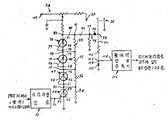
Translated fromKorean제1도는 케이블 자켓의 연속단면의 두께 및 편심률을 측정하기 위해 본 발명을 사용하는 초음파장치를 도시하고 절연도체의 코어의 연속단면 주위에 프라스틱 재료로 된 자켓을 압출하기 위한 라인(line)을 도시한 전체사시도.1 shows an ultrasonic apparatus using the present invention to measure the thickness and eccentricity of a continuous section of a cable jacket and shows a line for extruding a jacket of plastic material around the continuous section of the core of the insulated conductor. Full perspective view shown.
제2도는 제1도에 도시한 물통의 단면을 확대 도시하고 물통을 통하여 나아가는 피복된 코어에 관련해서 크리스탈을 형성하는 4개의 변환기의 위치상태를 도시하고 케이블자켓의 편섬률을 나타내고 아날로그형태로 측정을 나타내기 위해 콘솔(console)이 승강한 상태를 도시한 도면.2 shows an enlarged view of the cross section of the bucket shown in FIG. 1 and shows the position of the four transducers that form the crystal in relation to the coated core running through the bucket and shows the partial deflection of the cable jacket and measured in analog form. Figure showing a state in which the console is raised to show.
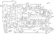
제3도는 초음파 측정을 하는데 사용된 4채널 중의 한 채널을 도시하고 4채널에 모두 공통인 소자들을 도시한 도면.3 shows one of the four channels used for making ultrasonic measurements and shows the elements common to all four channels.
제4도는 케이블에 펄스들을 보내도록 변환기들 중의 하나를 여기(excite)시키고 되돌아 오는 펄스들을 증폭시키기 위한 제3도에 도시한 펄서-리시버회로를 상세하게 도시한 도면.FIG. 4 shows in detail the pulser-receiver circuit shown in FIG. 3 for exciting one of the transducers and amplifying the return pulses to send pulses to the cable.
제5도는 자켓 두께를 지시하는 시간 기간을 확인하기 위해 해독펄스의 발생을 제어하도록 사이버신호와 의미심장한 측정신호사이를 분별하기 위한 제2도에 도시한 리시버-논리회로를 상세하게 도시한 도면.FIG. 5 shows in detail the receiver-logic circuit shown in FIG. 2 for discriminating between cyber and significant measurement signals to control the generation of decryption pulses to confirm the time period indicating jacket thickness.
제6도는 제2도에 도시한 장치의 등각에 관련된 파형을 도시하고 파형에 의한 변화곡선을 지시하기 위한 길이를 갖고 있는 그래프도.FIG. 6 is a graph showing waveforms corresponding to the conformal angle of the apparatus shown in FIG. 2 and having a length for indicating a change curve by the waveforms. FIG.
본 발명은 선형(strand) 물체의 연속단면을 초음파로 측정하는 방법에 관한 것으로, 특히 선정된 통로를 따라 나아가는 케이블의 연속단면 주위에서 압출된 자켓의 두께와 편심률을 초음파로 측정하는 방법에 관한 것이다.The present invention relates to a method for ultrasonically measuring a continuous section of a linear object, and more particularly, to a method for ultrasonically measuring the thickness and eccentricity of a jacket extruded around a continuous section of a cable running along a selected passage. will be.
통신산업 분야에서 사용하기 위한 케이블의 한 예에서, 금속방습층은 방수접합선을 형성하도록 함께 잡착된 방습층의 중첩연부로서 선정된 통로를 따라 나아가는 케이블코어 주위에 세로로 피복된다. 그 다음, 프라스틱 재료로 된 자켓은 방습층의 외향면에 접착되는 케이블코어의 자켓으로서 코어와 방습층 위에 압출된다. 이때 이 자켓이 피복된 케이블은 자켓의 온도를 감소시키기 위해 비교적 긴 물통을 지나간다.In one example of a cable for use in the telecommunications industry, the metal moisture barrier is longitudinally coated around a cable core running along a passageway selected as an overlapping edge of the moisture barrier layer held together to form a watertight line. The jacket of plastic material is then extruded over the core and the moisture barrier as a jacket of the cable core which is bonded to the outward side of the moisture barrier. The jacketed cable then passes through a relatively long bucket to reduce the jacket's temperature.
자켓의 편심률 뿐만 아니라 자켓의 벽 두께를 계속적으로 모니터하는 것이 바람직하다. 자켓을 모니터하면 자켓의 균일한 두께를 유지할 수 있고 또 적용 가능한 최소의 자켓 두께를 적용하므로서 프라스틱재료의 낭비를 방지할 수 있다. 또 편심률을 모니터하면, 압출장치를 조절하여 최종 생산물이 진원이탈(out-of-round)되는 것을 방지할 수 있다.It is desirable to continuously monitor the jacket's wall thickness as well as the jacket's eccentricity. By monitoring the jacket, it is possible to maintain a uniform thickness of the jacket and to avoid wasting plastic materials by applying the minimum applicable jacket thickness. By monitoring the eccentricity, the extruder can be adjusted to prevent the end product from being out-of-round.
종래에는 프라스틱 자켓에 직접 접촉시킨 전극과 금속층간의 용량을 측정하여, 금속방습층 위로 압출된 프라스틱 자켓의 두께를 모니터하였다. 그러나 내부 자켓을 둘러싸는 금속방습층이 없기 때문에, 종래의 동적용량기술은 사용할 수 없었으며 오프-라인 테스트를 사용해야만 하였다.Conventionally, by measuring the capacity between the electrode and the metal layer in direct contact with the plastic jacket, the thickness of the plastic jacket extruded over the metal moisture barrier. However, because there is no metal moisture barrier around the inner jacket, conventional dynamic capacitance technology could not be used and had to use off-line testing.
효과적인 제어를 하기 위하여, 프라스틱이 케이블 코어 위에 압출된 후에 가능한한 빨리 이 자켓의 두께를 모니터하는 것이 바람직하다. 종래에는, 케이블자켓의 온도가 내려갈 때까지 케이블자켓에 전극이 접촉하지 못하도록 케이블이 물통을 통과한 후에 모니터를 실시했다. 자켓압출이 필연적으로 일어나는 지점에 가까이 있는 비접촉 자켓두께측정장치는 압출기에 접속된 궤환제어장치를 최적의 상태로 하거나 자켓편심률과 두께를 모니터하도륵 조정을 행하는 동작자가 사용하기 위해 표시된다. 이러한 방법을 사용하므로서 자켓재료의 절약을 기할 수 있는 것이다.For effective control, it is desirable to monitor the thickness of this jacket as soon as possible after the plastic is extruded onto the cable core. Conventionally, monitoring was performed after a cable passed through a water bottle so that an electrode did not contact a cable jacket until the temperature of a cable jacket fell. The non-contact jacket thickness measuring device, which is close to the point at which the jacket extrusion inevitably occurs, is marked for use by an operator who makes optimum adjustments to the feedback control device connected to the extruder or monitors the jacket eccentricity and thickness. By using this method, the jacket material can be saved.
종래의 측정장치는 각각 브릿지회로로 공급되는 자기코일과 용량픽업프로브(probe)를 도시한 미국특허 제3, 407, 352호와 제3, 500, 185호에 예시되어 있다.Conventional measuring devices are illustrated in US Pat. Nos. 3, 407, 352 and 3, 500, 185, which show magnetic coils and capacitive pick-up probes supplied to bridge circuits, respectively.
고상물체의 두께 측정에 초음파를 이용하는 기술은 이미 종래에 공지된 것이며 보통 2가지 기술로 구분할 수 있다. 하나는 펄스를 송신하고 장치가 돌아오는 반향(echo)을 기다리는 펄스반향이용방법이고, 또 하나는 공명(resonance)을 이용하는 것으로서, 초음파신호의 파장이 검사 중인 물체의 두께의 정수비에 도달할 때까지가 귀환신호의 피크(peak)라는 원리를 이용하는 방법이다.The technique of using ultrasonic waves to measure the thickness of a solid object is already known in the art and can be generally divided into two techniques. One method is pulse echo, which transmits a pulse and waits for echo to return the device. The other is using resonance. When the wavelength of the ultrasonic signal reaches an integer ratio of the thickness of the object under inspection, Up to this method uses the principle of the peak (peak) of the feedback signal.
편심률과 두께를 측정할 때는 초옴파펄스반향기술을 이용하는 것이 이상적이다. 기계적인 크리스탈 링잉(ringing)을 만들기 위해서 고압전위를 사용하여 크리스탈을 전기적으로 여기시킨다. 이 기계적인 동작은 압력 또는 음파의 형태로, 냉각물통의 물과 같은 냉각물질을 통해 측정되는 케이블로 이송된다.When measuring eccentricity and thickness, it is ideal to use the ultra-ohm pulse echo technique. The crystal is electrically excited using a high voltage potential to make mechanical crystal ringing. This mechanical action is transferred to a cable, measured in the form of pressure or sound waves, through a cooling material, such as water in a cooling bucket.
냉각물질과 검사 중인 케이블과 같은 물체간의 음향의 비정합에 따라서, 음파에너지의 일부가 반사되고 그 일부는 검사 중인 물체매체를 통해 계속 진행할 것이다. 검사 중인 물체의 각 중간면에서, 이와 유사한 변형이 생긴다. 반향신호는 자켓의 두께를 측정하도록 처리된다.Depending on the mismatch of sound between the cooling material and the object, such as the cable under test, some of the acoustic energy will be reflected and some will continue through the object medium under test. In each intermediate plane of the object under examination, a similar deformation occurs. The echo signal is processed to measure the thickness of the jacket.
종래에는, 일반적으로 관(tube)과 같은 선형물체를 초음파 측정할 때, 라인 훠커스(focus)를 가진 크리스탈이 관의 세로측과 평행하게 놓이도톡 위치설정되었다. 그러나 관을 제조할 때, 관의 강도는 관의 연속단면의 측방향 동작을 미리 배제한다. 이것은 케이블의 연속단면이 냉각통을 통과할 때 생기는 측방향동작과는 다르다. 초음파 측정에 관한 종래의 특허로서는 미국특허 제3, 423, 992호, 제3, 474, 664호, 제3, 509, 752호 및 제3, 605, 504호 등이 있다.Conventionally, when ultrasonically measuring a linear object such as a tube, a crystal with a line focus has been placed in parallel with the longitudinal side of the tube. However, when producing a tube, the strength of the tube precludes the lateral motion of the continuous section of the tube. This is different from the lateral action that occurs when a continuous section of cable passes through the cooling trough. Conventional patents relating to ultrasonic measurement include US Pat. Nos. 3, 423, 992, 3, 474, 664, 3, 509, 752 and 3, 605, 504.
그러나, 이들 종래의 기술에서는 압출된 직후에 케이블자켓의 연속단면의 두께 및 편심률을 모니터할 수 있는 설비를 제공하지 못하였고 다만 케이블이 전진하고 있는 동안 의미있는 이들 신호만을 측정할 수 있었다.However, these prior arts did not provide a facility to monitor the thickness and eccentricity of the continuous section of the cable jacket immediately after extrusion, but could only measure these signals while the cable was moving forward.
본 발명의 방법에서, 온신호와 오프 신호는 자켓 외부 표면으로부터의 제1반향(echo)펄스의 수신시간과 그 물체의 내부 표면으로부터의 제2반향펄스의 수신시간간의 경과시간에 관련되는 온신호와 오프신호간의 시간기간에 발생된다. 이 온신호와 오프신호는 제1펄스가 시작된 후 소정의 시간 후에 발생하는 제2펄스에 의하여 소정의 최소진폭을 갖는 제1, 제2반향펄스를 수신할 때만이 자동적으로 발생되어 온신호와 오프신호간의 경과시간을 측정한다.In the method of the present invention, the on signal and the off signal are on signals related to the elapsed time between the reception time of the first echo pulse from the outer surface of the jacket and the reception time of the second echo pulse from the inner surface of the object. In the time period between the signal and the OFF signal. The on signal and the off signal are automatically generated only when the first and second echo pulses having a predetermined minimum amplitude are received by a second pulse generated a predetermined time after the first pulse is started. Measure the elapsed time between signals.
좀더 상세히 설명하면, 초음파신호가 투사된 케이블자켓으로부터 반사된 반향펄스가 검사되는 기간인 검사기간을 설정하기 위한 방법이 제공된다. 한 초음파펄스가 케이블자켓내로 송신되고 그 다음 부재의 한 표면에서 반사된 제1반향펄스와 그 반대표면에서 반사된 제2반향펄스가 수신되며, 이때 무관한 저레벨신호의 수신은 격리된다. 자격검사를 위해서 제1반향펄스가 검사되고 그 다음 제2반향펄스가 검사된다. 자격검사 제1반향펄스의 수신에 응답하여 온신호를 발생하며 제1반향펄스의 자격검사가 시작되고 자격심사 중인 제1반향펄스에 응답하여 제어펄스의 발생을 가능하게 촉진한다. 제1반향펄스의 검사와 제2반향펄스에 관련된 자격검사의 수신에 응답하여, 제2반향펄스에 관련된 자격검사의 특성검사가 시작되고, 오프신호가 발생된다. 온신호와 오프신호간의 지속기간은 제1반향펄스의 수신과 제2반향펄스의 수신간의 경과시간에 관련된다. 온신호와 오프신호간의 경과시간이 측정되고 가능한 장치의 조건은 유효한 제2반향펄스에 응답하여 제어펄스를 발생하게 된다. 측정된 경과시간은 제어펄스의 발생에 응답하여 자켓두께를 나타나게 한다.More specifically, a method is provided for setting an inspection period which is a period in which echo pulses reflected from a cable jacket on which an ultrasonic signal is projected are inspected. One ultrasonic pulse is transmitted into the cable jacket and then the first echo pulses reflected from one surface of the member and the second echo pulses reflected from the opposite surface are received, where the reception of the irrelevant low level signal is isolated. The first echo pulse is inspected for qualification and then the second echo pulse is examined. The qualification test generates an on signal in response to the reception of the first echo pulse, and the qualification test of the first echo pulse is initiated and facilitates the generation of the control pulse in response to the first echo pulse under qualification. In response to the examination of the first echo pulse and the reception of the qualification test relating to the second echo pulse, the characteristic test of the qualification test relating to the second echo pulse is started, and an off signal is generated. The duration between the on signal and the off signal is related to the elapsed time between the reception of the first echo pulse and the reception of the second echo pulse. The elapsed time between the on signal and the off signal is measured and possible device conditions generate a control pulse in response to a valid second echo pulse. The measured elapsed time gives the jacket thickness in response to the generation of the control pulse.
본 발명의 특징은 이하 첨부도면을 참고하여 설명되는 특정 실시예의 상세한 설명에서 더욱 쉽게 이해될 수 있을 것이다.Features of the present invention will be more readily understood in the detailed description of specific embodiments described below with reference to the accompanying drawings.
제1도를 참조하면, 자켓(제2도 참조)이 피복된 케이블(12)을 만들기 위해 포리에티렌과 같은 프라스틱재료로 케이블코어(11)의 연속단면을 피복하기 위한, 참조번호 10으로 표시한 장치가 도시되어 있다. 제1도에서 알 수 있는 바와 같이, 이 장치(10)은 번호 14로 표시된 압출기와, 이 압출기의 하류측에 있는 냉각통(16)을 포함한다. 코어 11의 연속단면은 캡스턴(17)에 의해 프라스틱 물질이 압출되는 압출기(14)를 통해 전진한다. 그 다음 케이블(12)의 연속단면은, 냉각통(16)을 통과하여 릴(18)에 감긴다.Referring to FIG. 1, indicated by
코어(11) 위로 압출된 자켓(13)(제2도 참조)의 두께 "d"와 이 자켓의 편심률을 가장 효과적으로 조절하기 위해서 일반적으로 번호 20으로 표시된(제1도와 제2도 참고)한초음파자켓 측정장치가 라인(10)상에 배치된다. 이 장치(20)는 자켓된 코어(11)의 연속단면이 물통(14) 속으로 들어갈 때 즉시 자켓의 두께와 편심률을 모니터한다. 이 초음파자켓 두께측정장치(20)는 최소한 하나의 크리스탈(21)(제2도 참조)에서 필요로하는 펄스-반향측정기술을 사용하도록 설계되어 있다. 냉각통(16)의 물은 케이블자겟(13)에 초음파 에너지를 전송하기 위한 결합매체의 역할을 한다.In order to most effectively control the thickness "d" of the jacket 13 (see FIG. 2) extruded over the core 11 and the eccentricity of the jacket, it is generally indicated by the number 20 (see FIGS. 1 and 2). An ultrasonic jacket measuring device is disposed on the
자켓(13)의 두께 "d"를 검사하기 위해서, 자켓 주위의 몇몇 지점에서 두께를 측정할 필요가 있다. 이것은 또한 케이블자켓(l3)의 편심률을 측정하기 위해서도 필요한 것이다.In order to examine the thickness "d" of the jacket 13, it is necessary to measure the thickness at some point around the jacket. This is also necessary to measure the eccentricity of the cable jacket l3.
제2도에서 알 수 있는 바와 같이, 다수의 크리스탈(21-21)은 자켓된 케이블(12)의 원주로부터 떨어져 있다. 이때 각 크리스탈은 냉각통(16)의 물과 같은 냉각매체속에 그 일부가 잠기게 된다. 이 크리스탈(21-21)은 미소영역에 될 수 있는 한 많은 에너지를 집중시킬 수 있는 것을 선택해야만 한다. 바람직한 크리스탈은 훠커스 라인을 갖는 것이며, 이 훠커스라인은 케이블(12)을 횡단한다. 또한 크리스탈(21)의 선택에 중요한 것은 가능한 서로 다른 많은 재료에 대해서 또 제조환경에 대해서 모든 기대되는 크기의 케이블에 사용할 수 있도록 만들어진 것이어야 한다.As can be seen in FIG. 2, the plurality of crystals 21-21 are separated from the circumference of the jacketed
또 하나의 고려해야할 중요한 특성은 크리스탈(21)의 감쇄율이다. 이 감쇄율이 매우 빠르지 않으면, 자켓(13)의 두께를 확실히 지시할 수 없게 된다. 즉, 펄스반향들(제6(a)도의 반향 I과 반향 II)이 혼신되어 구별할 수 없게 된다.Another important characteristic to consider is the attenuation rate of the
다수의 서로 다른 형의 크리스탈에 대해 시험을 했다. 시험 결과 연지르콘산염 크리스탈이 가장 적당한 것으로 밝혀졌다. 왜냐하면 이 크리스탈은 동일 여기에 대해 이들 황산염 크리스탈의 경우의 10MHz보다 더 큰 신호를 발생하며 감쇄특성도 더 좋기 때문이다.Many different types of crystals were tested. Testing has shown that soft zirconate crystals are the most suitable. This is because the crystals generate a larger signal than the 10 MHz of these sulphate crystals with the same excitation and better attenuation.
크리스탈(21-21)은 주기적인 기계응력을 야기하는 전압 임펄스에 의하여 여기된다. 이들 응력은 여기서는 냉각통의 물인 결합매체 속에서 고주파의 압력경사 또는 파형을 발생시킨다. 감쇄정현파로 강도가 변하는 이 파형들은 그 일부가 음향임피단스의 비정합 때문에 반사된(제6(a)도의 시간 T에서) 케이블자켓(13)의 표면으로 전파된다. 이에 의해 외부표면반향(제6(a)도의 반향 I)이 발생된다.Crystals 21-21 are excited by voltage impulses causing periodic mechanical stress. These stresses generate high frequency pressure gradients or waveforms in the coupling medium, here the water of the cooling tube. These waveforms whose intensity changes with the attenuation sinusoidal wave propagate to the surface of the cable jacket 13, part of which is reflected (at time T in Fig. 6 (a)) because of the mismatch of the acoustic impedance. Thereby, external surface echo (echo I in FIG. 6 (a)) is generated.
또한 압력파의 일부는 케이블자켓(13) 내부로 전파되어 이 케이블자켓의 내향으로 접한 도면에서 제2반사가 일어난다. 이것은 제2반향 또는 내부표면반향(제6a도의 반향 II)을 결정한다. 표면과 물체간의 상호관계를 참조하면 여기에 첨부된 명세서와 청구범위에 있는 "계면(facing)"이란 단어는 표면이 물체의 방향으로 결정되는 것으로 이해될 것이지만, 꼭 물체에 접착되거나 근접할 필요가 없다.In addition, a part of the pressure wave propagates into the cable jacket 13, and a second reflection occurs in the drawing facing inwardly of the cable jacket. This determines the second echo or the inner surface echo (echo II in FIG. 6a). Referring to the interrelationship between a surface and an object, the word "facing" in the specification and claims appended hereto will be understood to determine that the surface is determined in the direction of the object, but need not necessarily adhere to or adjoin the object. none.
반향신호들간의 시간차(제6(a)도의 2t)를 결정하는 것이 여기서의 측정기술이다. 이러한 시간차는 케이블자켓(13)의 두께 "d"에 직접 관련된다. 두께의 데이타는 포리에티렌에서 음속이 일정한가의 여부에 달려 있다. 실험결과에 의하면 이 속도는 일정했고, 식 2d=Vt가 성립한다. 여기서 d=포리에티렌 두께, V=음속, t=반향의 시간차이다. 반향의 시간차는 측정되고, 음속 V는 알고 있어서(약 0.051cm/㎲), d가 쉽게 결정된다. 자켓(13)의 내부 앞에서 냉각되는 포리에티렌의 표면에서 전파속도로 불균형하게 될 수도 있다.The measurement technique here is to determine the time difference (2t in Fig. 6 (a)) between the echo signals. This time difference is directly related to the thickness "d" of the cable jacket 13. The data of thickness depend on whether or not the speed of sound is constant in the polystyrene. Experimental results show that this velocity is constant and the equation 2d = Vt holds. Where d is the thickness of the polystyrene layer, V is the speed of sound, and t is the reverberation time. The time difference of the reverberation is measured, and the sound velocity V is known (about 0.051 cm / cc), so d is easily determined. It may also be unbalanced at the propagation speed on the surface of the porietirene cooled in front of the interior of the jacket 13.
각각의 크리스탈(21-21)은 다수의 채널(22-22)(제3도 참조) 중 관련된 하나에 전기적으로 접속되어있다. 각 채널(22-22)은 해당 크리스탈(21)과 일직선을 이루는 물체의 여러 내부표면에서 수신된 펄스반향들간의 시차를 케이블자켓(13)의 두께에 비례하는 출력으로 변환시키는 다수의 소자들을 포함한다.Each crystal 21-21 is electrically connected to an associated one of the plurality of channels 22-22 (see also FIG. 3). Each channel 22-22 includes a number of elements that convert the parallax between pulse echoes received at various internal surfaces of the object in line with the corresponding
또, 다른 소자를 추가하여 4개의 채널(22-22)과 함께 번호 25로 표시된 전기회호를 구성한다. 두께 및 편심률에 대한 회로(25)의 출력은 동작자를 위해서 콘솔(26)(제2도 참조)에 표시된다.In addition, another element is added to form an electric circuit numbered 25 with four channels 22-22. The output of
제3도를 참조하면, 전형적인 채널(22-22)을 도시하고 있으며 여기에는 4채널에 공통인 다른 소자들도 포함되어 있다. 각각의 채널(22-22)는 번호 27로 표시된 관련 펄서 리시버에 전기적으로 접속된 크리스탈(21-21) 중 관련된 것들을 하나씩 포함한다. 펄서리시버(27)는 특수 설계된 것으로서, 관련 크리스탈에서 고유주파수로 신호를 발생하도록 각 싸이클마다 크리스탈(21-21)의 관련된 것에 펄스를 최초로 전송하기 위해서 사용된다. 연속적으로 각 싸이클마다, 펄서리시버(27)은 검사 중인 케이블(12)로부터 펄스방향을 수신하도록 작용한다.Referring to FIG. 3, typical channels 22-22 are shown, including other elements common to the four channels. Each channel 22-22 includes one of the relevant ones of the crystals 21-21 that are electrically connected to the associated pulser receivers, indicated by the
이 펄서리시버(27)은 선(28)을 따라 리시버논리회로(29)에 전기적으로 접속되어 있다. 리시버는리회로(29)는 펄스반복주파수회로(PRF)(30)에서 명령을 받자마자 펄서리시버(27)를 동작시켜 관련변환기 크리스탈(21)을 펄스시킨다. 제3도에서 알 수 있는 바와 갈이, 펄스반복주파수회로(30)는 선(31)을 따라 리시버논리회로(29)에 접속되어 있다. 리시버논리회로(29)는 검사 중인 케이블(12)로부터 수신된 반향펄스를 검사하도륵 설계되어 있고 자켓(13)의 두께측정에 무관한 이 펄스들을 제거할 수 있다. 이와같이, 리시버논리회로(29)는 제1 및 제2반향신호를 구별할 수 있을 뿐만 아니라 잡음스파이크와 유효신호를 구별할 수있는 고유정보를 가지고 있어야만 한다.This
리시버논리회로(29)는 다수의 10진 카운터(33-33)를 포함하는 카운터(32)에 전기적으로 접속되어 있다.The
이 카운터(32)는 리시버논리회로(29)에서 나온 출력펄스의 폭을 측정하는 것이다. 이 카운터(32)는 발진기(34)에 의해 펄스되고(제6i도의 발진기 출력 참조), 펄서리시버(27)에 의해 수신된 펄스가 리시버논리회로(29)에 의해 유효하게 되면 버퍼메모리뱅크에 펄스카운트를 축적하도록 설계되어 있다.This
카운터(32)에서 나온 축적된 디지탈 카운트는 디지탈 카운트를 아날로그 전압으로 변환시키는 디지탈-아날로그변환기(36)로 전이된다. 이 디지탈-아날로그변환기(36)의 기능은 카운터(32) 내에 축적된 디지탈 카운트와 일치하는 아날로그 전압을 제공하는 것이다. 이 전압이 해당 채널용 두께 표시이다. 적당한 크기로 된 연속적인 아날로그전압은 그 채널(22)의 계기(37)(제2도 참조)에 나타난다. 이 표시에 의해 동작자가 한 채널에 해당하는 원주의 일부에서 케이블자켓의 두께 "d"를 연속적으르 모니터할 수 있다.The accumulated digital count from the
선택적인 방법으르, 버퍼에 축적된 카운터 출력을 디지탈 전자계산기(도시하지 않음)에 접촉시켜, 데이타분석 및 감소를 행할 수도 있다.Alternatively, the counter output stored in the buffer may be brought into contact with a digital electronic calculator (not shown) for data analysis and reduction.
케이블자켓(13)의 편심률을 측정하기 위해, 편심률 측정회로(38)가 채널(22-22)의 각각의 디지탈-아날로그변환기(36)에 접속되어 있다. 이 편심률 측정회로(38)는 제2도에 도시한 바와 같이 케이블자켓(13)의 상, 하단에서의 자켓 두께 "d"와 좌, 우단간에서의 자켓 두께를 비교하기 위한 것이다. 물론, 이들 비교측정을 수평축과 수직축을 따라서 할 필요는 없고, 케이블자켓(13)의 좌표측에 대해 원점에 대칭인 곳에서 하면 된다.In order to measure the eccentricity of the cable jacket 13, an eccentricity measuring circuit 38 is connected to each of the digital-
편심률 측정회로(38)는 제2도에 도시한 바와 같이 자켓(13)의 상단 두께에서 하단 두께를 빼고, 이 값을 100배 하고 공칭 자켓 두께로 나누어 공칭 자켓 두께의 백분율을 만들어낸다. 이와같은 계산은 케이블자켓(13)의 좌우측 부분에서의 두께에 대해서도 행해진다. 이 각각의 측정 값은 편심률 측정회로(38)와 연결된 상-하 계기(39)와 좌우 계기(40)에 표시된다.The eccentricity measuring circuit 38 subtracts the bottom thickness from the top thickness of the jacket 13, as shown in FIG. 2, and multiplies this value by 100 times to create a percentage of the nominal jacket thickness. This calculation is also performed for the thickness at the left and right portions of the cable jacket 13. Each of these measured values is displayed on the upper and
펄스반복 주파수회로(30)는 PRF 시간이라 불리는 어떤 시간에 선(31)을 지나 상기 제1채널용 접점(43)에 신호(
펄서 리시버(27)는 제1SCR(54)이 온되도록 이 제1SCR(54)의 제어전극(53)에 고압전류펄스 인가되게하기 위해서 펄싱소자(48)로부터 펄스가 인가되는 트리거링회로(51)(제4도)를 포함한다.The
SCR(54)는 상업상 이용할 수 있는 소자로서 싸이레이숀-형(thyration-like) 동작특성을 갖는 2-상태반도체 소자이다. 정상적인 때는 비-도전 상태로 있는 SCR(54)는 음극(56)과 양극(57)이 있으며, 양극(57)은 정전압원(58)과 같은 외부수단에 의해 순방향으로 바이어스된다. 제어전극(53)은 바이어스전압에의해 적절히 여기될 때 작용하여 SCR 54가 도전상태로 되게 한다.SCR 54 is a two-state semiconductor device having a thyration-like operation characteristic as a commercially available device. Normally, the SCR 54, which is in a non-conductive state, has a negative electrode 56 and a
제4도에서 알 수 있는바와 갈이, 제1SCR(54)의 양극(57)은 접점(59)와 접점(61)을 통하여 제2SCR(63)의 음극(62)에 직렬로 접속되어 있다. 접점(61)은 제2SCR(63)의 게이트(64)에 접속되어 있다. SCR(63)의 양극(66)은 접점(67, 68)을 통하여 SCR(71)의 음극(69)에 접속되어 있다. 접점(68)은 SCR(71)의 제어전극(72)에 접속되어 있다. 끝으로, SCR(71)의 양극(73)은 접점(74, 76)을 통하여 SCR(78)의 음극(77)에 접속되어 있고, 접점(76)은 SCR의 게이트(79)에 접속되어 있다.As can be seen from FIG. 4, the
또, SCR(78)의 양극(81)은 접점(82)를 통해 접지(83)에 접속되어 있다. SCR(54, 63, 71 및 78)은 각각 병렬로 접속된 저항(84, 86, 87 및 88)을 가지고 있다. 접점(82)는 선(89)를 따라 저항(84 및 86-88)의 직렬단에 접속된 접점(91)에 접속되고 그 다음 캐패시터(92)를 통해 접점(93)에 접속된다. 이 접점(93)은 다이오드(96)의 음극(94)에 접속되고 양극은 접점(98)을 통해 변환기(21-21)의 관련된 것에 접속되어 있다. 다이오드(96)은 진폭이 작은 잡음신호를 차단하는 역할을 한다. 만일 이 다이오드(96)가 없다면, 회로의 동작 부분에서 나온 작은 잡음신호가 접점(93)을 통해 선(98)에 이동되어 관련된 변환기(21)에서 나온 반향신호를 저감시키게 된다. 이들 저레벨 잡음신호에 응답하여, 다이오드(96)은 정 또는 부 익스커션(excursion)에 대해 개방회로로 작용한다.The
이 브로킹 다이오드(96)는 접점(98)을 통하고 선(101)을 따라서 저항(102)을 통해 접점(103)에 접속되고 광대역 영상증폭기(106)의 입력(104)에 접속되어 있다. 이 증폭기(106)의 입력(104)에서 큰 부전압이 나타나는 것을 피하기 위해, 다이오드(107)을 접점(103)에 접속되어 있는 선(108)에 삽입하였다.This breaking
광대역 저잡음 영상증폭기(106)은 케이블(12)로부터의 궤환반향신호를 수신, 증폭 및 전송한다. 저레벨전류궤환신호는 약 1-3V 정도로 증폭되어야만 한다. 광대역 영상증폭기(106)는 사용된 반도체 소자가 저잡음 특성을 갖는 것을 선택해야 한다. 이와같이 하여, 리시버논리회로(29)로 전송을 하기 위해 수신되고 증폭된 신호는 잡음에 기인한 신호보다 더욱 강해지므로, 의미있는 신호를 정확하게 탐지할 수 있는 것이다.The wideband low
검사를 하기 위해서 반향펄스가 회로(25)에 의해 수신되는 동안 잡음레벨을 감소시키기 위한 설비를 펄서리시버회로(27)에 설치하는 것은 내부 자켓의 두께를 측정하기 위해 장치(20)를 사용할 때 특히 중요하다. 내부 자켓으로부터 수신된 펄스반향은 진폭이 외부 자켓으로부터 수신된 것보다 더 작다. 이것은 내부 자켓의 포리에티렌 표면이 다 불균일하기 때문이다. 내부 자켓의 피크 및 계곡에 의해 케이블의 타게트(target) 면적이 감소되고, 따라서 반향신호의 전단부 진폭이 감소하게 된다. 또한 이들 피크 및 계곡은 전기반향신호의 일부에서 위상차를 발생한다. 이 위상차는 저진폭을 갖는 위상에 의해서 증가될 수 있다. 반향신호강도는 내부 및 외부 자켓간에서 또 케이블의 크기에 따라 변화하지만, 모든 형태의 포리에티렌케이블에 대해 고정된 이득장치를 사용할 수 있다.Installing a device in the
내부 자켓은 제이블크어(11) 주위에서 수축되고 약간 불균일한 외향표면이 생긴다. 이에 비해, 외부 자켓은 이 외부 자켓의 외향표면이 더 균일하게 되도륵 하는 관형금속시일드(shield) 위로 압출된다. 이것은 저인계 픽업을 위한 셋팅을 불가피하게 하고 잡음신호를 픽업하기 위한 기회를 부득이 증가시키게 한다.The inner jacket shrinks around the Jablec 11 and results in a slightly uneven outward surface. In contrast, the outer jacket is extruded over a tubular metal shield that makes the outer surface of the outer jacket more uniform. This inevitably leads to a setting for low handover pickup and inevitably increases the chance of picking up a noise signal.
펄서 리시버(27)의 SCR(54,63, 71 및 78)과 광역영상증폭기(106)를 포함하는 회로의 펄스발생기 부분이 접속된 다이오드(96)는 리시버(27)가 반향을 청취하는 시간 중에 임피던스레벨을 높이는 기능을 한다. 이것은 장치(20)의 작동에 관계한 잡음의 관점에서 더욱 양호한 광대역 영상증폭기의 작동을 가능하게 한다.The
다이오드(96)는 회로(27)의 펄스형성부분 또는 펄스발생기를 광대역 영상증폭기(106)에 접속시키는 선(89)상에 위치하여, 제1방향으로 회로를 오픈시킨다. 또 다른 방향, 제4도에 도시한 바와 갈이 왼쪽에서, 다이오드(96)는 변환기(21-21) 중에 관련된 하나를 펄싱하는 부전류를 통과시킨다.The
탐지장치는 기대된 신호의 특성에 적용된다. 예를들면, 변환기(21)와 케이블(12)간의 거리와 물 매체에서의 음파의 전파속도를 알 수 있기 때문에, 펄스반향신호가 기대되는 시간간격을 알 수 있다. 따라서, 초음파장치(20)는 이 시간간격(이후부터 "윈도우폭"이라고 함) 동안만 펄스반향 신호를 받아들이도톡 설계되어 있다.The detection device is adapted to the characteristics of the expected signal. For example, since the distance between the
포리에티렌의 두 음성특성, 즉 전파속도와 음향임피던스는 특히 중요하다. 이들은 포리에티렌의 온도에 따라 달라지므로, 광대한 온-라인 검사가 필요하다.The two voice characteristics of foretylene, namely propagation speed and acoustic impedance, are particularly important. These depend on the temperature of the polystyrene and therefore require extensive on-line inspection.
매체에서의 종음파(여기서 전단응력파는 중요하지 않음)의 속도방정식은 다음과 같다.The velocity equation of the longitudinal wave (where shear stress wave is not important) in the medium is

여기서 Vℓ=종속도Where Vℓ = longitudinal velocity
μ=전단계 수μ = step number
ρ= 밀도ρ = density
Kc=체적탄성계수Kc = volume modulus
포리에티렌의 음향임피던스는 반향신호의 크기에 영향을 주기 때문에 매우 중요하다. 음향임피던스방정식은 다음과 같다.The acoustic impedance of polystyrene is very important because it affects the magnitude of the echo signal. The acoustic impedance equation is
Z=ρVℓZ = ρVℓ
두 매채 사이의 계면에서의 반사량은 음향임피던스의 차가 증가함에 따라 증가한다. 이 정도의 임피던스 부정합이 반향진폭을 결정한다. 물과 포리에티렌의 계면이 제1반향을 결정하고 포리에티렌과 공기, 강철, 알루미늄 또는 프러딩(flooding) 화합물간의 계면이 제2반향을 결정한다.The amount of reflection at the interface between the two media increases as the difference in acoustic impedance increases. This impedance mismatch determines the echo amplitude. The interface between water and porietyrene determines the first echo, and the interface between porietyrene and air, steel, aluminum or floating compounds determines the second echo.
실험에 의하면, 포리에티렌에 대한 음향임피던스는 고온에서 감소한다. 특히 제1반향은 제2포리에티렌 표면에서의 더 큰 음향부정합으로 인하여 진폭이 제2반향보다 매우 작다. 또 제2반향신호는 주기가 제1반향신호보다 더 길다. 이들 신호특성은 리시버논리회로(29)의 "정보"설계에 유리하게 이용된다. 신호의 크기가 표면의 불균일로 인하여 상당히 변화되는 내부 자켓의 측정에서, 이 "정보"는 특히 유익한 것이다. 만일 반향의 진폭 또는 지속기간을 최소치 이하로 순간적으로 떨어뜨리면, 부정확한 측정이 이루어지지는 않는다. 그 대신, 최종의 양호한 측정은 카운터(32)를 버퍼(buffer)하는 레지스터에 남아 정확한 두께 출력을 유지한다.Experiments have shown that the acoustic impedance for porietirene decreases at high temperatures. In particular, the first echo is much smaller in amplitude than the second echo due to a larger acoustic mismatch at the second polyetherylene surface. The second echo signal has a longer period than the first echo signal. These signal characteristics are advantageously used for the "information" design of the
리시버논리회로(29)는 다음과 같은 기대되는 신호특성을 검사하도록 설계되어 있다.The
(1) 신호반향이 펄스 송신 후 일정한 시간(윈도우폭이라 함) 내에 발생되는지 여부,(1) Whether signal echo occurs within a certain time (called window width) after pulse transmission,
(2) 각 반향의 초기극성이 부정적인지 여부,(2) whether the initial polarity of each echo is negative,
(3) 제1반향펄스가 제2반향펄스에 비하여 지속기간이 더 짧은지 여부(제6(a)도 참조),(3) whether the first echo pulse has a shorter duration than the second echo pulse (see also paragraph 6 (a)),
(4) 제1반향과 제2반향간에 최소한 200ns의 시간이 존재하는지 여부,(4) whether there is at least 200 ns of time between the first and second echoes,
(5) 제2반향펄스의 진폭이 요구된 제1반향펄스의 최소치보다 더 큰지 여부(제6(a)도 참고),(5) whether the amplitude of the second echo pulse is greater than the minimum of the required first echo pulse (see also sixth (a)),
(6) 제2반향펄스가 최소한 0.700㎲의 기간 동안 지속하는지 여부 등을 체크한다.(6) Check whether the second echo pulse lasts for at least 0.700 0.7.
만일 이들 특성이 제1 및 제2반향펄스의 특정결과에 대해 충족된다면, 리시버논리회로(29)에서 해독펄스형의 명령이 카운터(32)에 전달되어 시간 2t(제6(h)도 참조) 동안 기록된 카운트를 유효데이타로 축적한다.If these characteristics are met for the specific results of the first and second echo pulses, then the
제5도에서 접점(43)은 단안정 멀리바이브레이터(112)의 입력단(111)에 접속되어 있다. 이 멀리바이브레이터(112)는 출력단(115)으로부터 선(113)을 따라 제2단안정 멀티바이브레이터(114)에 인가되는 지연펄스를 발생한다. 멀티바이브레이터(114)의 한 출력단(116)은 선(117)을 따라 접점(118)을 통해 정전압 임계검파 및 비교기(120)의 입력단(119)와 부전압 비교기(122)의 입력단(121)에 접속되어 있다.In FIG. 5, the contact 43 is connected to the
임계검파기(120, 122)는 리시버논리회로(29)의 비교기 부분(123)에 포함되어 있다. 제5도에 도시한 바와같이, 회로(28)의 이 비교기 부분(123)은 광역 영상증폭기(106)에 접속되어 있는 RF 입력단(124)을 포함한다. 입력(124)은 임계검파기(120, 122)의 입력단(126, 127)에 각각 인가된다.The
검파기(120, 122)에는 임계값을 초과할때 부의 진출력이 나타난다. 제5도에 도시한 바와 같이, 임계검파기(120)의 출력(128)은 부의 논리를 가진 NOR 게이트(131)의 입력(129)으로 인가된다. 이 NOR 게이트는 입력(129) 또는 다른 입력(133)에 부레벨 또는 저레벨이 인가되면 그 출력(143)에 정레벨 또는 고레벨이 나타난다. 검파기(122)의 출력(132)은 NOR 게이트(131)의 다른 입력단(133)에 인가된다. NOR 게이트(131)의 출력(134)은 접점(136, 137)을 거쳐 입력신호의 극성을 바꾸는 인버터(138)에 인가되고, 그 다음 선(139)를 따라 플립플롭(141)에 전달되어 이 플립플롭을 셋트한다.Negative advance forces appear in
플립-플롭(141)은 펄스반복 주파수회로(30)에 접속된 크레어 및 리세트(clear or reset) 입력(142)를 가지고 있고 또 접점(144)를 통해 홀드-오프(hod off) 펄스발생기(147)의 입력(146)에 접속된 출력(143)을 갖고 있다. 단안정멀티바이브레이터인 홀드-오프 펄스발생기(147)는 선(148)을 통해 유효 펄스발생기(149)에 접속되어 있다. 이 유효 펄스발생기(149)도 단안정멀티바이브레이터이다.The flip-flop 141 has a clear and reset input 142 connected to the pulse
멀티바이브레이터(149)의 출력(151)은 선(152)를 따라 정의진 NAND 게이트(l54)의 입력(153)에 접속되어 있다. 또한 제5도에 도시된 바와 같이, 접점(136)은 선(156)을 따라 NAND 게이트(154)의 다른 입력(157)에 접속되어 있다. 정신호가 동시에 NAND 게이트(154)의 입력(153, 157)에 인가되면, 부레벨 또는 저레벨의 출력이 출력단(158)에 나타난다.The output 151 of the
NAND게이트(154)의 출력(158)은 선(159)을 따라 플립-플롭(162)의 셋트 입력(161)에 접속되어 있다.Output 158 of
플립-플롭(162)은 지연된
이것은 멀티바이브 레이터(112)의 출력(115)으로 부터의 지연펄스의 후단부에 의해 플립-플롭의 입력(163)에 리셋트신호를 인가하는 것에 기인한다.This is due to applying a reset signal to the
플립-플롭(162)의 출력(164)은 선(166)을 따라 접점(167)을 통해 플립-플롭(169)의 "D"입력으로 표시된 입력(168)에 접속된다. "C"입력으로 표시된 플립-플롭(169)의 크럭입력(171)은 선(173)을 따라 멀티바이브레이터(149)의 출력(172)에서 부터 인가된다.The
입력(170)에 인가된 펄스 반복 주파수신호(
플립-플롭(187)은 펄스반복 주파수회로(30)로부터 나온 리셋트 입력(188)을 가지고 있고 이것은 멀티바이브레이터(112)에 의해 발생된 펄스의 후단부에 지연된다. 플립-플롭(187)의 출력(189)은 선(191)을 따라 정의 진 NAND 게이트(193)의 입력(192)에 접속된다. 또한, 접점(144)은 선(194)을 따라 NAND게이트(193)의 다른 입력(196)이 접속되어 있다. 이 NAND게이트는 제5도에 도시한 바와 같이 부출력펄스 또는 저출력펄스를 발생한다.The flip-
플립-플롭(187)의 다른 출력(197)은 선(198)을 따라 단안정 멀티 바이브레이터(201)의 입력(199)에 접속되어 있다. 멀티바이브 레이터(201)는 제2펄스 반향의 특성을 검사하기 위한 홀드-오프 펄스 발생기로 작용한다. 그 출력(202)은 선(203)을 따라 접점(204)에 접속되고 선(206)을 통해 제2반향 유효펄스발생기(208)의 입력(207)에 접속되어 있다. 이 발생기(208)도 단안정 멀티바이브 레이터이다.Another
이 멀티바브레이터(208)의 출력(209)은 선(211)을 따라 정의 진 NAND게이트(213)의 한 입력(212)에 접속되어 있고, 이 NAND 게이트의 다른 입력(214)은 선(216)을 따라 접점(181)이 접속되어 있다.The output 209 of this
NAND 게이트(213)는 출력(217)에서 부신호를 발생하여 선(218)을 따라 입력(221)을 통해 플립-플롭(219)을 셋트하도록 되어 있다.NAND gate 213 generates a negative signal at
플립-플롭(219)은 소위 링잉 플립-플롭으로서, 펄스 반복 주파수회로(30)에서 부터 나온 리셋트 입력(222)을 가지고 있다. 또 이 플립-플롭(219)은 출력(223)에서 신호를 발생하여, 선(224)을 따라 정의 진 NAND 게이트(227)의 입력(226)에 전달하도록 되어 있다. 이 NAND게이트(227)는 선(229)을 따라 접점(167)에 접속된 입력(226)과 입력(228)에 정신호 또는 고신호를 인가하자마자 부신호 또는 저신호를 발생하고, 신호가 선(231)을 따라 단안정 멀티바이브레이터(233)인 펄스발생기의 입력(232)에 전달되어 이 멀티 바이브레이터를 작동시키는 것이다.Flip-
접점(204)은 선(236)을 따라 검파기회로(123)에 있는 진폭비교기(238)의 입력(237)에 접속되어 있다. 이 비교기(238)의 출력(239)은 선(241)을 따라 플립-플롭(242)에 접속되어 있다. 이 플립-플롭(242)도 펄스반복 주파수회로(30)에서부터 나온 리셋트 입력(240)을 가지고 있다.The contact 204 is connected along the line 236 to the
이 플립-플롭(242)에서부터 나온 출력(243)은 선(244)를 따라 멀티바이브레이터(233)의 입력(246)에 접속되어 있다.Output 243 from this flip-
이 멀티 바이브레이터(233)의 다른 입력(247)은 선(248)을 따라 멀티바이브레이터(114)의 출력(249)에 접속되어 있다.The
멀티바이브레이터(233)는 윈도우폭의 끝에서 명령이 떨어지자마자 기억장치(도시되지 않음)에 카운트를 축적시키는 해독펄스를 발생시키도록 되어 있다.The multivibrator 233 is configured to generate a decode pulse that accumulates counts in a storage device (not shown) as soon as the instruction drops at the end of the window width.
장치(20)의 작동을 양호하게 하기 위해서, 케이블(12)의 상면위로 약 3.8 내지 7.6cm의 물이 있다는 것을 알아야 한다. 또 크리스탈 변환기(21-21)의 각각의 하단부분도 물에 적셔져 있어야만 한다. 현존하는 설비에서 이들 요건을 충족하는 것은 약간 어려운 일이다.In order to facilitate the operation of the
원통형의 장치를 변환기중 가장 위에 있는 것 위에서 케이블(12)와 계합하게 설치하는 방법도 있다. 이때는 이 용기에 진공을 가하여 그 내부로 물을 끌어올려서 그 내부의 크리스탈 하단부분이 물에 적셔지도록 한다.Another method is to install the cylindrical device in engagement with the
여기서 사용하는 용어중 "검사한다"거나 "모니터한다"거나 "측정한다"는 것은 어떤 측정량을 기준치에 대해 비교하는 것으로 해석한다. 예를들면, 임계검파기(120, 122)는 반향펄스가 최소한의 임계진폭보다 큰것인지를 체크한다.As used herein, the term "inspect", "monitor" or "measure" is interpreted as comparing a measurand to a reference value. For example,
한편, 비교기(238)는 제2반향 펄스의 피크 진폭이 선정된 값보다 더 큰가를 비교한다. 물론 장치(20)를 좀더 복잡하게 구성하여 실제 지속시간과 실제진폭이 나타나게 할 수도 있다.On the other hand, the
검사과정에서 허용되는 오차율에 따라서, 장치(20)는 좀더 복잡하지 않게 구성할 수도 있다. 예를들면, 채널(22)은 기록된 어떤 제2펄스를 검사하므로서 제2 반향펄스의 피크진폭을 일정시간후 허용하여, 두 펄스의 임계치를 자동적으르 체크할 수 있다. 물론 이것은 요구된 임계치를 갖는 제1반향펄스가 유효펄스라는 가정하에서이다. 선택적인 것으로, 장치(20)는 제2 반향펄스의 피크진폭이 선정된 값보다 더 큰지, 두 펄스의 임계값이 선정된 값보다 위에 있는지를 체크하고, 도 제1반향펄스의 지속시간이 설정된 값보다 더 짧은지를 체크하도록 구성할 수 있다.Depending on the error rate allowed during the inspection process, the
여기서 설명되는 한 실시에서 제1 및 제2 반향펄스가 유효하다면 이들 펄스간의 시간카운트를 기록한다. 제1펄스는 그 진폭이 일정 임계값보다 크고 그 지속시간이 선정된 값보다 짧으면 유효하게 된다. 또 제2펄스는 그 피크진폭이 선정된 값을 초과하고 그 지속기간이 선정된 기간보다 더 클때 유효하게 된다.In one implementation described herein, record the time count between these pulses if the first and second echo pulses are valid. The first pulse is valid if its amplitude is greater than a certain threshold and its duration is shorter than the predetermined value. The second pulse becomes effective when the peak amplitude exceeds the selected value and the duration is larger than the selected period.
제1 및 제2 반향펄스의 유효연속은 소위 윈도우폭에 나타나야 한다.The effective sequence of the first and second echo pulses should appear in the so-called window width.
본 발명은 실제 펄스진폭값과 지속시간을 나타내게 할 수도 있고, 또 검사중인 자켓의 특정재료와 관련된 것들과 비교하기 위한 반향펄스의 주파수 내용도 나타나게 할 수 있다.The present invention may show the actual pulse amplitude and duration, and also show the frequency content of the echo pulses for comparison with those associated with the particular material of the jacket under test.
본 장치는 케이블(12)이 전진하는 동안 케이블 자켓두께를 동적으르 측정하기 위한 것이기 때문에 구조가 복잡하다. 따라서 관벽 두께의 측정 때와는 다르게, 측정과정에서 케이블의 측방향이동과 자켓(13)의 변형을 고려해야만 한다. 종래의 장치에서는 케이블의 사이즈나 다른 파라메터가 변하면 수동으로 조작해야만 했다. 그러나 본 발명의 장치에서는 이들 변화에 대해 자동적으로 조정된다.The apparatus is complex in structure because it is intended to measure the cable jacket thickness dynamically while the
논리회로는 종래의 관에서 경험한 것보다 케이블 자켓에서의 비교적 더많은 불완전 상태를 고려하여 고유정보를 가져야만 한다.Logic circuits should have unique information in view of the relatively more incomplete state in the cable jacket than experienced in conventional tubes.
여기서 사용된 논리소자, 즉 NAND게이트와 NOR게이트, 그리고 쌍 안정소자, 즉 플립플롭과, 단안정소자 즉, 일단락 멀티바이브레이터 등을, 고레벨 또는 정레벨 전압이 2진 "1"을 나타내고 저레벨 또는 제로레벨전압이 "0"을 나타내는 정논리회로의 입장에서 그 작동을 설명하겠다. 또한 일반적으로 전체적인 신호발생방법에 있어서, 여러소자의 입력 및 출력을 고레벨 또는 저레벨의 입장에서 설명하겠다.The logic elements used here, i.e., the NAND and NOR gates, and the bistable elements, i.e. flip-flops, the monostable elements, i.e., the single-ended multivibrators, etc., the high level or the constant level voltage represents a binary " 1 " The operation will be explained from the standpoint of the positive logic circuit in which the level voltage indicates "0". In general, in the overall signal generation method, the input and output of the various elements will be described in terms of high level or low level.
정의 진 NAND 게이트에서는 그 전체 입력단이 고레벨의 입력이 주어질 때만이 저레벨의 출력이 발생된다. 그리고 그밖의 다른 어떤 입력결합에 대해서 출력은 항상 고레벨이다.In a positive NAND gate, a low level output occurs only when the entire input stage is given a high level input. And for any other input combination, the output is always high.
부의 진 NOR 게이트에서는 어떤 입력단에든지 저레벨의 신호가 가해지면 항상 고레벨의 출력이 발생된다. 그리고 저레벨의 입력이 전혀 없을 경우에만 저레벨의 출력이 발생된다.In a negative true NOR gate, a high level output is always generated when a low level signal is applied to any input. The low level output is generated only when there is no low level input.
플립-플롭이라는 것은 두개의 안정상태를 갖는 쌍안정 멀티바이브레이터를 의미한다. 이 플립-플롭은그 입력단에 하나의 입력을 인가하여 한 상태에서 다른 상태로 스위치되기 위한 다수의 입력을 포함할 수 있다. 또, 전형적으로 플립-플롭은 두개의 출력단이 있으나, 그중의 하나만을 사용한다. 이 플립-플롭이 제1의 리셋트 또는 크레어 상태에 있을 때 고레벨 또는 "1" 출력은 저출력 전압레벨을 발생하고, "0"출력은 고출력전압레벨을 발생한다. 출력 전압레벨은 이 플립-플롭이 제2상태로 셋트될 때 역으로 된다.Flip-flop means a bistable multivibrator with two steady states. This flip-flop may include a number of inputs for switching from one state to another by applying one input to its input. Typically, flip-flops have two output stages, but only one of them is used. The high level or " 1 " output generates a low output voltage level and the " 0 " output generates a high output voltage level when this flip-flop is in the first reset or crease state. The output voltage level is reversed when this flip-flop is set to the second state.
일단락 멀티바이브레이터란, 그 입력에 "1"을 인가하자마자, "0"에서 "1"로 가는 입력이 선택된 지속시간을 갖는 "1"레벨의 단일 출력펄스를 만드는 일종의 단안정 멀티바이브레이터이다. 지연 일단락은 선택된 기간을 갖는 "1"의 출력펄스에 의해 "1"이 그 입력단에 인가된후 선정된 기간의 지연이 생기는 멀티바이브레이터를 가리키는 것이다.A single-ended multivibrator is a type of monostable multivibrator that, as soon as "1" is applied to its input, an input going from "0" to "1" produces a single output pulse of "1" level with a selected duration. The delay one end refers to a multivibrator in which a delay of a predetermined period occurs after "1" is applied to the input terminal by an output pulse of "1" having a selected period.
인버터란 입력에 "1"이 인가될 때 "0" 출력을 발생하고, 반대로 "0"이 입력에 인가될 때는 "1"의 출력을 발생하는 회로를 말한다.The inverter refers to a circuit that generates an "0" output when "1" is applied to the input, and conversely, an "1" output when "0" is applied to the input.
종래의 플립-플롭, 리셋트 및 크레어 입력단에
본 발명 원리에 따른 초음파 측정장치(20)의 작동방법을 제4도와 제5도를 참조하여 설명한다. 펄스반복주파수회로(30)는 선(41)을 따라 접점(43)에 펄스를 인가하고 그 다음 선(44)을 따라 펄싱장치(48)에 펄스를 인가한다. 그 다음 광학 아이소레이터(48)는 트리거링펄스를 트리거링회로(51)에 인가한다.The operation method of the
트리거링회로(51)는 제어전극(53)에 정전압을 인가하여서 음극전위에 과도한 양극을 인가하여 제2 SCR(63)을 동작시키는 제1 SCR(54)을 동작시킨다. 이와 마찬가지로 SCR(71, 78)이 모두 동작된다.The triggering
4개의 SCR(54, 63, 71 및 78)은 저항(84, 86-88)에 의해 균등하게 분배된 인가전위를 유지할 수 있다. 그러나, 제1 SCR(54)이 도전성으로 될 때, 나머지 세 SCR은 인가전위를 유지하지 못하고 이후에 설명하는 바와 같이 파손된다.The four
이와같이 직렬접속된 4개의 SCR(54, 63, 71 및 78)을 연속동작시키므로서 캐패시터(92)가 방전하여 관련변환기(21)에 전압펄스가 인가된다. 변환기(21)에 인가된 펄스는 부의 펄스로서 크기가 200-250V이고 지속시간이 약 60ns이다. 이 펄스는 다이오드(96)를 통해 선(98)을 따라 접지에 인가된다. 변환기(21)에 이 펄스를 인가하므로서 이 변환기(21)에서 일렬로 자켓된 케이블(21)의 단면과 연동하는 압력파가 발생된다.In this way, the capacitor 92 is discharged while the four
SCR(54, 63, 71 및 78)이 동작된 직후, 접점(91)의 전위는 낮아 실질적으로 0이며, 반면 접점(93)의 전위는 약 200-250V 이다. 이 전압에 의해 캐패시터(92)가 방전을 한다. 캐패시터(92)는 즉시 방전하지 않도록 선택된다. 이 캐패시터(92)는 일정시간 후에 다이오드(107)로 부터 접점(98)과 다이오드(96)를 통해 방전한다. 또 이 캐패시터는 양단의 전위가 0으로 있는 동안 SCR을 통해 방전한다.Immediately after the
그 다음 전원(109)으로부터 전류가 흘러 캐패시터(92)를 원래의 상태로 재충전한다. SCR에서의 전류는 SCR(78)로부터 SCR(54)로 향하는 방향으로 인가된다. 또 이 전류는 수 암페어의 피크전류에서 SCR이 차단상태로 되는 전류레벨 이하로 떨어진다. 이것은 트리거펄스가 통과한 후부터 그 다음 트리거펄스가 발생되기 전까지의 동안에 일어난다는 것에 주목해야 한다.Current then flows from
제5도의 리시버 논리회로(29)는 펄서리시버(27)에 의해 수신된 반향펄스가 선택된 진폭범위 이내에 있을 경우 정펄스를 발생하도록 되어 있다. 리시버 논리회로(29)에는 반향펄스에 대한 외측대역과 내측대역을 결정하기 위한 논리회로가 설치되어있다. 펄서리시버(27)에 의해 수신된 반향펄스의 진폭이 선택된 진폭보다 큰 경우, 이 회로는 부 또는 외측 대역펄스를 기록할 것이다.The
펄서리시버(27)에 의해 수신된 유효반향펄스 셋트는 제6도에 도시한 바와 같이 제1 반향펄스 I에 대해 시간 2t만큼 떨어져 있으며 주기가 개시된 후 약 40-120㎲ 동안 생긴다. 이 제1 반향펄스는 관련된 링잉변환기 크리스탈(21)에서 방사된 펄스가 자켓(13)의 외향 표면에 닿을 때 발생된다. 제2 반향펄스 II는 변환기 크리스탈에서 방사된 펄스의 반사되지 않은 부분이 자켓(13)의 내향표면에 닿을 때 발생된다.The set of effective echo pulses received by the
반향펄스 I의 진폭은 가열된 포리에티렌 자켓과 냉각통(14) 내의 물 사이의 음향임피던스 비정합의 함수이다. 단향펄스 I의 진폭은 가열된 포리에티렌자켓과 코어(11)간의 음향임피던스 비정합의 함수이다.The amplitude of echo pulse I is a function of the acoustic impedance mismatch between the heated polystyrene jacket and the water in cooling vessel 14. The amplitude of the unidirectional pulse I is a function of the acoustic impedance mismatch between the heated polystyrene jacket and the core 11.
또 제1 단향펄스는 제2 반향펄스보다 진폭과 지속기간이 더 작다.Also, the first unidirectional pulse has a smaller amplitude and duration than the second echo pulse.
"윈도우-폭"(제6(b)도 참조, 약 90-120㎲) 동안에는, 리시버 논리회로(29)에서 제1 반향펄스를 수신하자마자 홀드-오프펄스(제6(d)도 참조)를 발생한다. 유효펄스(제6(e) 참조)는 제1홀드-오프 펄스가 끝난 직후 시작된다. 제2 유효펄스는 제1 반향펄스의 진폭이 감쇄한 후에 발생되는 것이 바람직하다. 리시버 논리회로(29)에서 정의 출력(158)을 지시한다면, 이때 유효 제1펄스가 발생된다는 것을 알 수 있다.During " window-width " (see also FIG. 6 (b), about 90-120 Hz), the hold-off pulse (see also FIG. 6 (d)) is received as soon as the
그러므로, 제2 반향펄스의 초기에, 제2 홀드-오프 펄스가 발생되고, 제2 유효펄스는 제2 홀드-오프펄스의 종료시 시작한다.Therefore, at the beginning of the second echo pulse, a second hold-off pulse is generated, and the second effective pulse starts at the end of the second hold-off pulse.
제2 유효 펄스는 제1 유효펄스와는 달리, 제2 반향펄스의 감쇄기간 동안 발생된다. 결과적으로, 제2 유효펄스의 관련된 회로부분은 제2 반향펄스가 임계대역의 선정된 한계밖에 있다는 것을 지시하는 부의 출력(217)을 나타낸다.The second valid pulse is generated during the attenuation period of the second echo pulse, unlike the first valid pulse. As a result, the associated circuit portion of the second effective pulse represents a
리시버 논리회로(29)가 제1 반향신호로부터 부의 출력을 수신한 경우, 리시버 논리회로는 제2반향을 찾지 않으므로, 제1주기 동안 해독펄스를 발성하지 않는다.When the
또한 유효 펄스는 냉각통(16)의 물 매체에 있는 기포로 인한 잡음 신호의 부정한 픽업을 방지한다. 만일 잡음신호가 제1 반향 펄스보다 앞서는 경우, 이 회로는 이 잡음신호를 제1 반향신호로 픽업하고 그 다음 정말의 제1 반향신호를 제2 반향신호로 유효하게 하려고 한다. 이러한 경우, 기대된 정-부 연속신호를 수신하지 못한 리시버 논리회로(29)는 해독 펄스를 발생하지 못한다.The effective pulse also prevents fraudulent pickup of the noise signal due to air bubbles in the water medium of the cooling
또, 펄스 반복 주파수회로(30)는 채널(22-22)의 동작 및 상호 작용을 제어한다. 이것을 수행하기 위해서, 펄스반복 주파수회로(30)는 채널(22-22)의 각각에 대해, 주기가 약 1ms인 4개의 펄스반복 속도신호를 하나씩 발생한다. 이 4개의 펄스는 약 250㎲(제6(j)도 참조)까지 스태거(stagger)되어, 이에 의해 4채널의 동작순서의 스태거링이 일어난다. 이와 같이, 상부 채널(22)에서 시작해서 그 다음은 하부로, 또 좌측과 우측 채널로 진행하여, 상부 채널에서의 모든 유효한 작동은 하부 채널과 관련된 전 이펄스가 발생하기 전에 제1의 250㎲ 이내에 일어난다.In addition, the pulse
PRF 회로(30)는 각각의 주기 동안 회로(29)를 조절한다. PRF 회로에서 나온 부의 진 펄스로서 정의된

또한 PRF 회로(30)는 윈도우-폭(제6(b)도 참조)인 선정된 시간 동안만 관련 변환기(21)의 반향펄스를 받아 들이도록 회로(29)를 제어한다. PRF 회로(30)에서 나온 펄스는 멀티바이브레이터(112)의 입력(111)에 인가된다.The
멀티바이브레이터(112)에 의해 선정된 시간동안 윈도우 지연(제6(b)도 참조)이 일어나며, 이 윈도우 지연은 플립-플롭(162)의 리셋트 입력(163)에 인가되어 그 "0"출력(164)이 고레벨을 나타내도록 한다. 또한 이 지연펄스는 플립-플롭(187)의 리셋트입력(188)에 인가되어 고레벨 출력(197)이 저레벨을 나타내고 저레벨 출력(189)이 그 레벨을 나타내도록 한다. 선(1l3)에 인가된 지연펄스의 후단부에 의해 멀티바이브레이터(114)에서 윈도우-폭 펄스(제6도 참조)를 발생하게 된다. 윈도우 펄스에서의 소위 "윈도우-폭"이란 채널(22)에서 변환기(21-21)에 의해 케이블(12)로 방사된 펄스로부터 유효 펄스반향을 수신하는 시간을 의미하며 이러므로서 산란펄스를 방지하게 된다. 윈도우펄스의 끝은 검사주기의 끝으로 간주된다.A window delay (see also sixth (b)) occurs during the time selected by the multivibrator 112, which is applied to the
이때 리시버 논리회로(29)는 반향펄스의 수신에 따른 측정 과정을 더욱 제어하기 위한 펄스의 발생여부를 결정한다.At this time, the
윈도우펄스는 출력(116)에서 송신되고 접점(118)에 인가되어 검파기(120,122)를 작동가능하게 한다.The window pulse is transmitted at the output 116 and applied to the contact 118 to enable the
검파기회로(123)는 증폭기(106)에 의해 입력단자(124)에 인가된 정 또는 부의 반향펄스를 검파하기 위한 설비를 갖고 있다. 여기서 주목할 것은 윈도우 신호가 접점(118)에 나타날 때만이 한쌍의 임계진폭검파기(120, 122)가 동작한다는 것이다.The detector circuit 123 has a facility for detecting a positive or negative echo pulse applied by the
임계진폭 검파기(120)는 임계검파회로(123)의 입력단(124)에 유효 정반향 펄스를 인가하는 것에 응답하여 NOR게이트(131)의 입력(129)에 부신호를 인가토록 되어 있다. 한편, 임계진폭 검파기(122)도 유효부반향펄스에 응답하여 NOR 게이트(131)의 입력(133)에 부신호를 인가하도록 되어있다.The
임계검파회로(123)는 제1 반향펄스가 최소한 선정된 임계진폭 이상일 때만 NOR 게이트(131)에 신호를 인가하도록 되어 있다. 선정된 최소진폭을 가진 반향펄스를 외측 대역이라고 부르며, 진폭 검파기(120 또는 122)중의 하나로 하여금 부신호를 발생하게 한다. 만일 이 진폭이 선정된 임계진폭치보다 작은 경우에는, 이 진폭을 내측대역이라 부르며, 부신호를 나타내지 않는다.The threshold detection circuit 123 applies a signal to the NOR gate 131 only when the first echo pulse is at least equal to or more than a predetermined threshold amplitude. The echo pulse with the selected minimum amplitude is called the outer band and causes one of the
포리에티렌 자켓(13)이 냉각될 때, 이 자켓에서 나온 반향펄스의 진폭은 증가한다. 본 발명의 장치는 가능한한 압출기에 가까운 곳에서 자켓의 두께와 편심률을 측정하기 위해 설계된 것이다. 따라서, 여기서의 측정은 가열된 상태의 포리에티렌재료에 대한 것이다. 검파기(120, 122)는 포리에티렌 자켓(13)의 외향 표면에서 기대된 것과 일치하는 선정된 최소진폭을 가진 펄스단을 검파하도록 선택 조정된다.When the porietirene jacket 13 is cooled, the amplitude of the echo pulses coming out of this jacket increases. The apparatus of the present invention is designed to measure the thickness and eccentricity of the jacket as close to the extruder as possible. Therefore, the measurement here is for the polystyrene material in the heated state.
그 다음, 리시버 논리회로(29)는 제1반향펄스를 검사하여 이 제1 반향펄스의 지속기간이 선정된 기간보다 더 크지 않은지를 검사한다. 실험에 의하면, 포리에티렌 자켓의 외향 표면과 물의 계면에서 기대되는 제1펄스는 지속기간이 매우 짧아, 예를들면 1/2㎲정도였다. 이에 비해, 포리에티렌 자켓의 내향표면과 코어 또는 시일드층간의 계면으로부터 나온 제2 반향펄스는 그 지속기간이 1-2㎲였다. 이것은 고주파 에너지를 제거하려는 포리에티렌 특성과 제2 계면에서의 보다 큰 반사때문에 기인한다. 그러므로 어떤 유효신호이전간에 모두 지속시간 및 진폭의 크기면에서 성립된 기준을 충족할 수 있어야 한다.The
제1 반향 펄스의 진폭이 선정된 값보다 큰 경우, 임계전파기(120 또는 122)는 NOR게이트(131)의 입력단자(129 또는 133)에 각각 신호를 인가한다. 그 다음 이에 의해 게이트(131)는 정 또는 고전압레벨 신호를 접점(136, 137)를 거처 인버터(138)에 인가한다. 그 다음 이 인버터(138)에서 선(139)를 거쳐 플립-플롭(141)에 부신호가 인가된다. 이에 의해 플립-플롭(141)의 출력(143)이 고레벨 전압으로 셋트되어 접점(144)에 고레벨신호가 나타난다.When the amplitude of the first echo pulse is greater than the predetermined value, the
플립-플롭(141)은 그 다음 측정주기초기에
접점(144)에서의 고전압레벨신호는 NAND 게이트(193)의 입력단(196)에 입력으로 인가된다. 제5도에 도시한 바와 같이, 플립-플롭(l87)의 압력(188)에 인가된 지연
입력(188)에 지연

이를 방지하기 위해서, 지연
접점(144)에 고레벨이 나타난다는 것은 최소한 부분적으로 유효한 제1반향 신호를 가리킨다. 이러한 가정을 증명하기 위해, 그 지속기간이 약 500ns이고 시간간격 또는 갭(gap)이 신호가 없을때에도 발생하는지를 판단하는 일종의 체크를 시작한다. 이 목적을 위해서, 접점(144)에서의 고렐벨에 의해 제1 홀드-오프 펄스 멀티바이브레이터(147)의 입력(146)에 고레벨신호가 인가된다. 접점(144)에서의 신호는, 그 전폭이 임계검파기(120 모는 122) 중의 하나에 의해 결정된 관계를 유지하고 있는한, 유효반향 펄스의 존재를 가리킨다.The appearance of a high level at
접점(144)에 신호를 인가하므로서 홀드-오프 멀티바이브레이터(147)에서 지연 또는 홀드-오프펄스(제6(d)도 참조)가 발생되어 제1 펄스가 유효 지속기간을 가진 것인지(예를, 면, 유효 제1 반향 펄스로서 자격이 있는 1/2㎲)를 판별한다. 이 홀드 오프 펄스 멀터바이브레이터(147)는 지속시간이 1/2㎲인 홀드 오프 펄스를 발생시키기 위한 것이다. 1/2㎲후, 홀드 오프펄스의 후단부에 의해 유효 펄스 멀티바이브레이터(149)에서 약 500ns의 펄스(제6(e)도 참조)가 발생된다.Applying a signal to the
이 동안, 이 펄스에 의해 NAND 게이트(154)의 입력(153)에 고레벨이 나타나서 이 NAND게이트를 동작가능하게 한다. 만일 반향펄스의 지속기간이 홀드 오프 펄스보다 더 길다면, 접점(136)에서 선(156)을 거쳐 NAND 게이트(154)의 입력(l57)에 고레벨이 인가된다. 이에 의해 NAND 게이트의 두 입력에 정의진 신호가 가해지고 출력(158)에는 저레벨의 신호가 나타난다.During this time, a high level appears at the input 153 of the
만일 과도한 지속기간 때문에 유효반향펄스 I이 수신되지 않았다는 것을 지사하는 반향펄스가 아직 나타날 경우에는, 이 신호가 기억되지 않는한 신호를 측정하는 것은 중단된다.If an echo pulse still appears indicating that an effective echo pulse I was not received due to excessive duration, measurement of the signal is stopped unless this signal is memorized.
플립-플롭(162)의 출력(164)은 입력(163)에 인가된 바와 같은 지연된
크록(clock) 입력 또는 "C"입력(171)이 멀티바이브레이터(169)에 의해 발생된 유효펄스의 정의 후단부에서 발생할때 만일 플립-플롭 169)의 "D"입력이 저레벨이라면, 출력(174)에는 저레벨이 나타단다. 이것은 갭이 없다는 것이며, 즉 제1 반향펄스가 무효의 것이라는 것과 일치한다. 만일 출력(174)이 저레벨을 나타낸다면, NAND 게이트(178)는 동작하지 않고 출력(174)은 저레벨로 남아 있는다. 그 다음
한편, 만일 반향펄스가 홀드 오프 펄스(유효 제1 반향펄스를 나타내는) 후에 사라진다면, NAND 게이트(154)의 입력(157)에 고레벨이 나타나지 않는다.On the other hand, if the echo pulse disappears after the hold off pulse (indicating a valid first echo pulse), no high level appears at the input 157 of the
NAND 게이트(154)는 작동되지 않고 또 플립-플롭(162)을 셋트하지 않으며, 출력(164)에서의 고레벨이 플립-플롭(169)의 "D"입력(168)에 나타난다. "D"입력은 입력(171)에 크록 "C"가 나타날 때 고레벨이기 때문에, 출력(174)은 고레벨이며, 게이트(178)의 입력(177)에서 고레벨이 나타나게 되어 이 게이트가 작동된다.
게이트(178)의 출력(177)에 고레벨이 나타난다면, 제1반향 펄스는 시간과 지속기간에 대해 유효한 것이다. 이것이 회로(29)로 하여금 제2 반향 펄스를 찾게한다.If a high level appears at the
접점(167)에서 나타나는 고레벨은 NAND게이트(227)의 입력(228)에 고레벨이 나타나게하여 이 게이트를 동작시킨다. NAND 게이트(227)의 작동은 수신된 제2펄스가 유효한 경우, NAND 게이트에서 해독펄스를 발생하여 카운터(32)에 카운트가 축적되도록, 이 게이트를 작동시킨다.The high level appearing at contact 167 causes the high level to appear at input 228 of
제2 반향펄스가 회로(29)의 입력(124)에 의해 수신될때, 임계검파기(120 또는 122) 중의 하나는 전술한바와 같이 작동하여 NAND 게이트로 하여금 그 출력(134)에서 고레벨신호를 발생하도록 한다. 이에 의해 선(139)을 거쳐 접점(181)을 통해 이미 동작된 NAND 게이트(178)의 입력(182)에 고레벨신호가 인가되어 NAND 게이트를 작동시킨다.When the second echo pulse is received by the
NAND 게이트(178)의 동작(제2 반향 펄스의 수신에 부분적으로 기인하는)은 출력(183)에서의 저레벨이 플립-플롭(187)의 입력(186)에 나타나도록 하여 이 플립-플롭을 셋트한다. 이것이 리시버 논리회로(29)로 하여금 제2반향 펄스를 볼 수 있도록 하는 조건이다. 또, 이것은 카운팅 주기의 끝을 의미한다(제6도참조). 플립-플롭(187)의 셋팅에 의해 출력(189)에서의 저레벨신호 즉 부신호가 NAND게이트(193)의 입력(192)에 나타나게 되어, NAND 게이트를 부동작 상태로 하고 출력에서 저신호의 생산이 중단된다. 이에의해 카운터(32)(제6(h)도 참조)에 의한 발진기출력의 카운트가 중단된다.Operation of NAND gate 178 (partly due to receipt of second echo pulse) causes the low level at
나머지 주기에서는 카운트가 버퍼(도시하지 않음)로 전이되는 제2 반향신호의 유효성을 판단한다. 유효판정과정은 제1 반향펄스에 대해 사용했던 것과 유사하게 제2 반향펄스에 대해서도 사용된다. 제2 반향펄스의 지속기간이 1/2-2㎲라는 것을 기억할 것이다. 제2 펄스를 검사하는 리시버 논리회로(29)의 이 부분은 1㎲지연을 부가하도록 구성되어 있다. 일단 펄스를 검사하고, 또 아직 임계진폭이 있을 경우에, 이 펄스는 기억된다. .In the remaining periods, the validity of the second echo signal in which the count is transferred to a buffer (not shown) is determined. The valid decision process is used for the second echo pulse similarly to the one used for the first echo pulse. You will remember that the duration of the second echo pulse is 1 / 2-2 ms. This portion of the
플립-플롭(187)을 셋팅하면 출력(197)에서의 저레벨신호가 그 레벨로 되고 선(198)을 따라 인가된다. 플립-플롭(187)에서 나온 펄스 상승단부는 제2 홀드 오프 펄스발생기(201)로 하여금 대략 1.0㎲의 지속기간을 갖는 하나의 펄스를 발생시키게 한다.Setting flip-
멀티바이브레이터(201)에 의해서 홀드 오프지연펄스를 발생할때, 신호가 접점(204)으로부터 선(236)을통해 임계검파기(238)의 입력(237)에 보내져 이 검파기를 작동시킨다. 제2 펄스의 정진폭은 임계검파기(238)에 의해 체크되어 제2 반향펄스의 진폭이 최초 임계값보다 매우 더 큰 선정된 값을 초과하는지를 검사한다. 제5도에 도시한 바와같이, 임계검파기(238)은 단지 정신호만 체크한다. 그러나, 본 발명에 의해 부의 익스커션(excursion)용 신호를 검사하기 위해서 다른 임계검파기를 회로(123)에 포함시킬 수 있다.When a hold off delay pulse is generated by the
최대 임계값 진폭이 초과될 경우, 검파기(238)은 선(241)을 따라 플립-플롭(242)의 입력에 저레벨신호를 인가하여, 이 플립-플롭을 셋트하고 출력(243)에 고레벨신호가 나타나게 한다. 출력(243)에서의 고레벨은 선(244)를 따라 멀티바이브레이터(233)의 입력(246)에 인가되어 이 멀티바이브레이터를 작동시킨다.When the maximum threshold amplitude is exceeded,
멀티바이브레이터(201)에 의해 발생된 펄스의 후단부는 멀티바이브레이터(208)에 나타나므로, 이 제2 펄스 유효 멀티바이브레이터(208)에서는 약 500ns의 유효 펄스(제6(g)도 참조)가 발생된다. 이 제2 유효펄스 멀티바이브레이터(208)는 출력(209)에서 선(211)을 따라 NAND게이트(213)의 입력(212)에 고레벨의 신호를 인가한다.Since the rear end of the pulse generated by the
또, 제5도에 도시한 바와같이, 유효 펄스의 지속기간 동안 정 또는 부의 임계값이 초과된 경우에는, 접점(137)으로부터 선(139)을 따라 접점(181)에 신호가 인가되고, 그 다음 선(216)을 따라 NAND게이트(213)의 입력(214)에 고레벨신호로서 인가된다. 제2 반향펄스의 임계값 검사는 사실상의 익스커션이 있는지를 검사하기 위해 필요한 것이다.In addition, as shown in FIG. 5, when the positive or negative threshold value is exceeded during the duration of the effective pulse, a signal is applied from the contact 137 to the contact 181 along the line 139. Along the next line 216 is applied to the input 214 of the NAND gate 213 as a high level signal. Threshold checking of the second echo pulse is necessary to check for the presence of virtual excursions.
고레벨신호가 제2 반향펄스의 존재를 지시하는 임계검파기(120 또는 122)중의 하나로부터 입력(214)이 인가되고 또 멀티바이브레이터(208)로부터 입력(212)으로 인가되면, 출력(217)에 저레벨신호가 나타나 플립-플롭(219)을 셋트한다. 플립-플롭(219)의 셋팅에 의해 고레벨신호가 선(224)를 거쳐 이미 작동가능하게된 NAND게이트(227)의 입력(226)에 나타난다.If the high level signal is applied from one of the
NAND게이트(227)이 작동하고, 그 다음 해독펄스를 발생하고 이미 진폭유효에 의해 동작가능한 일단락 멀티 바이브레이터(233)에 선(231)을 거쳐서 저레벨신호가 인가된다.The
NAND게이트(227)에 의해 멀티바이브레이터(233)에 인가되는 저레벨펄스가 발생하면 제1 펄스의 지속기간이 제2 반향펄스에 갭이 나타나는 기간인 1㎲보다 더 짧다는 것을 나타내고 도 제2 반향펄스의 지속기간이 1/2-2㎲라는 것을 나타낸다.When the low level pulse applied to the multivibrator 233 by the
윈도우 펄스가 중단되자마자, 해독펄스를 발생할 것인지에 관한 결정이 이루어진다. 이 윈도우 펄스와 중단은 선(248)을 거쳐 멀티바이브레이터(233)의 입력(247)에, 일단락 단안정 멀티바이브레이터에 의해 인가된 한 신호에 의해 지시된다. 멀티바이브레이터(242)로부터의 인력(246)에 의해 이미 동작 가능하게 된 멀티바이브레이터(233)는 NAND게이트(227)로부터 인가된 입력을 가지고 있다. 이 멀티바이브레이터(233)은 작동되어 카운터(32)를 지시하고 입력(247)에서 윈도우 펄스의 후단부를 수신하는 즉시 NAND게이트(193)로부터의 펄스폭을 기록한다.As soon as the window pulse is interrupted, a decision is made whether to generate a decode pulse. These window pulses and interrupts are indicated by a signal applied by the one-ended monostable multivibrator to the
발진기(34)에서는 펄스를 발생시킨다. 이들 펄스는 카운터(32)에 의해 카운트되며, 이 카운트는 제1홀드-오프펄스의 초기점에서 시작하고 제2 반향펄스의 초기점에서 끝나는데 이들간의 차이는 반향펄스간의 시간간격의 측정이다. 이 카운터(32)는 세개의 십진 카운터, 즉 각각의 십진 카운터에 연결된 4-비트 기억장치를 갖는 100, 10 및 1카운터를 포함한다. 적당한 펄스가 정-부 순서로 반향펄스 I과 II에 관련해서 발생된다면, 윈도우-펄스의"윈도우-폭"의 끝에서 해독펄스가 발생된다. 이에 의해 카운터(32)의 레지스터내에 축적된 카운트는 카운터의 카운팅 부분에서 카운터의 메모리 부분으로 전이된다. 그다음 이 메모리로부터의 카운트는 디지탈-아날로그 변환기(36)에 인가되어 이 디지탈-아날로그 변환기에서 자켓두께를 지시하는 계속적인 전압출력이 제공된다.The
여기서 주목할 것은, 그다음 순서의 유효해독펄스가 발생되어 관련 카운트를 이 버퍼로 전이시킬때까지 버퍼내에 이미 축적된 카운트가 바뀌지 않는다는 것이다. 회로(25)는 다음 유효 카운트가 수신될 때까지 이전의 카운트를 버퍼내에 보존하고, 무효카운트가 수신될 경우에는 이 카운트를 폐기한다.Note that the count already accumulated in the buffer does not change until the next valid read pulse is generated and transferred to this buffer. The
또 디지탈-아날로그 변환기는 연속 해독펄스간에 약 800㎲동안 구동되는 발광체를 포함하고 있다. 이들 발광체중 4개는 장치(20)과 연관된다. 만일 허용될 수 있는 측정이 행해진 경우, 이 발광체들은 그 시간의 약 80내지 90%동안 온상태로 있게된다. 한편, 이 신호를 잃은 경우에는 크리스탈(21)의 위치이탈이나 채널의 결점을 지시하는 발광이 전혀 없게 된다. 각각의 채널(22-22)에 대한 발광체는 본 장치의 작동에 이상이 생긴 경우, 동작자에게 경고하는 경고등으로 사용된다. 이 발광체는 해독펄스스트림(stream)이 계속 발생되면 계속 온상태로 있다. 그러한 조건하에서는 80%의 기본싸이클신호가 이 발광체를 구동한다. 케이블이크리스탈쪽으로 발진할 때에는, 크리스탈이 케이블을 보지 못하는 경우에 여기가 나타나지 않는 것처럼 발광체가 깜박거리는 경향이 있다.The digital-to-analog converter also includes a luminous body that is driven for about 800 ms between successive readout pulses. Four of these emitters are associated with the
장치(20)는 검사중인 자켓(13)의 두께를 기록하는 특징을 가지고 있다. 일반적으로, 최소한 두께가 20mils인 자켓(13-13)은 전혀 문제가 없다. 그러나, 자켓두께가 이보다 작은 경우에는 문제가 생긴다. 리시버 논리회로(29)는 제1홀드-오프 펄스발생과 유효부분에 대해 1㎲당 20mils을 조정하도록 되어있다.The
예를들면, 홀드 오프 펄스 멀티바이브레이터(147)는 관련 크리스탈(21)의 링잉감쇄시간에 최소한 일치하는 시간동안 홀드 오프 펄스를 발생해야만 한다. 감쇄시간이 0.5㎲로 낮은 크리스탈을 선택할 수 있다.For example, the hold off
그다음, 유효 펄스발생기(149)는 최소한 관련 크리스탈(21) 링잉의 1싸이클과 같은 시간동안 펄스를 발생해야만 한다. 크리스탈(21)은 5메가싸이클에서 신호를 발생하므로 이 펄스폭은 200ns정도로 낮아진다.The
이들 두 지속기간이 결정되면, 장치(20)의 연속적인 작동은 제1 반향에 대해 제1 홀드 오프 및 유효판정 과정이 끝날때까지 수신되지 않는 제2 반향펄스에 따라 좌우된다. 장치(20)를 두께가 20mils/㎲이하인 자켓을 측정하는데 사용하면 이들 요건들은 만족되지 않는다.Once these two durations are determined, the continuous operation of the
물론, 박벽자켓에 대해 보통 사용되는 프라스틱 절연재료를 사용하는 경우에는, 이 특정재료에서의 초음파 압력파의 속도가 비교적 느리기 때문에 반향펄스간의 시간은 더길다. 가열된 포리에티렌에서, 기대된 속도는 20mils이다. 따라서 포리에티렌으로 20mils이하의 자켓을 만드는 것은 반향펄스가 중첩한다는 문제를 야기한다. 그러나, 가열된 포리비닐 염화물로된 동일 두께에 대해서는, 반향 I과 II간의 시간경과가 더 길어 자켓이 얇더라도 중첩문제를 피할 수 있다.Of course, when using the plastic insulating material normally used for thin-walled jacket, the time between the reverberation pulses is longer because the speed of the ultrasonic pressure wave in this particular material is relatively slow. In heated polystyrene, the expected speed is 20 mils. Therefore, making a jacket of less than 20 mils from polyetherene causes the problem of overlapping echo pulses. However, for the same thickness of heated polyvinyl chloride, the overlap between the echoes I and II can be avoided even if the jacket is thinner.
물론, 제1 표면과, 이 제1 표면의 반대측에 있고 이들 간에 몇개의 서로 다른 재료층으로 서로 격리된 제2 표면간의 두께를 측정하는 것도 본 발명의 범위내에 들어간다. 또한, 케이블 자켓두께를 측정하는 대신에, 본 발명의 방법은 관에서와 같이 고체코어 또는 공동(hollow)코어의 연속단면을 둘러싸는 피복층의 연속단면의 두께를 측정하는데 사용할 수도 있다.Of course, it is also within the scope of the present invention to measure the thickness between the first surface and the second surface opposite the first surface and isolated from each other with several different layers of material therebetween. Also, instead of measuring the cable jacket thickness, the method of the present invention may be used to measure the thickness of the continuous section of the coating layer surrounding the continuous section of a solid core or hollow core, such as in a tube.
어떤 케이블 구조에서는, 내부 자켓이 각각의 관련된 반향펄스 쌍중의 제2 반향펄스가 신장해 있는 코어외피 또는 다른 재료와 계합되어 있다. 그러나, NAND게이트(193)에 의한 오프신호의 발생은 두께를 측정하기 위해 제2 반향펄스의 초기부분을 수신하는 즉시 일어난다는 것을 기억할 것이다. 또, 물론 제2 반향펄스의 피크진폭 및 지속기간 특성은 만족하게 된다. 다른 한편, 코어외피가 자켓의 내향표면에서 격리되어 있는 경우, 공기는 전송이 없는 오픈 스위치로 작용한다. 또 두께를 측정할 때 제2 반향펄스를 검사 및 사용하는 것은 아무런 손해를 끼치지 않는다.In some cable constructions, an inner jacket is associated with the core shell or other material in which the second echo pulses in each associated echopulse pair extend. However, it will be remembered that the generation of the off signal by the NAND gate 193 occurs immediately upon receipt of the initial portion of the second echo pulse to measure the thickness. In addition, of course, the peak amplitude and duration characteristics of the second echo pulse are satisfied. On the other hand, if the core shell is isolated from the inward surface of the jacket, the air acts as an open switch without transmission. In addition, inspecting and using the second echo pulse when measuring the thickness does not cause any damage.
이상에서 설명한 것은 단지 본 발명의 원리를 설명하기 위한 것으로서, 본 기술분야에 숙련된 기술자들에 의해 본 발명의 원리나 범위이내에서 수정을 가할 수도 있을 것이다.What has been described above is only intended to explain the principles of the present invention, and may be modified by those skilled in the art within the principles and scope of the present invention.
Claims (1)
Translated fromKoreanPriority Applications (1)
| Application Number | Priority Date | Filing Date | Title |
|---|---|---|---|
| KR7301085AKR800000140B1 (en) | 1972-07-05 | 1973-07-04 | Method of neasuring automatically successive sections of an elongated material |
Applications Claiming Priority (3)
| Application Number | Priority Date | Filing Date | Title |
|---|---|---|---|
| US268,973 | 1972-07-05 | ||
| US268,961 | 1972-07-05 | ||
| KR7301085AKR800000140B1 (en) | 1972-07-05 | 1973-07-04 | Method of neasuring automatically successive sections of an elongated material |
Publications (1)
| Publication Number | Publication Date |
|---|---|
| KR800000140B1true KR800000140B1 (en) | 1980-03-08 |
Family
ID=19198794
Family Applications (1)
| Application Number | Title | Priority Date | Filing Date |
|---|---|---|---|
| KR7301085AExpiredKR800000140B1 (en) | 1972-07-05 | 1973-07-04 | Method of neasuring automatically successive sections of an elongated material |
Country Status (1)
| Country | Link |
|---|---|
| KR (1) | KR800000140B1 (en) |
- 1973
- 1973-07-04KRKR7301085Apatent/KR800000140B1/ennot_activeExpired
Similar Documents
| Publication | Publication Date | Title |
|---|---|---|
| US3929006A (en) | Measuring article thickness ultrasonically | |
| US3827287A (en) | Methods of and apparatus for measuring the thickness of successive sections of a cable jacket | |
| US3916676A (en) | Method of and apparatus for measuring automatically successive sections of an elongated material | |
| US2280226A (en) | Flaw detecting device and measuring instrument | |
| US4953405A (en) | Ultrasonic measuring apparatus for measuring a predetermined boundary surface inside an object | |
| JPS6188146A (en) | Method and apparatus for inspecting glass bottles | |
| US3423992A (en) | Ultrasonic apparatus for measuring thickness or distances | |
| US4995260A (en) | Nondestructive material characterization | |
| KR800000140B1 (en) | Method of neasuring automatically successive sections of an elongated material | |
| JP3169534B2 (en) | Inundation detection method | |
| KR800000139B1 (en) | Automatic measuring device of continuous section of linear object | |
| JP3597182B2 (en) | Ultrasonic sound velocity measurement method and method for determining Young's modulus and Poisson's ratio based on these methods | |
| JPS617465A (en) | Ultrasonic wave tester | |
| US2683821A (en) | Unwanted reflection absorbing shear wave transducer | |
| NO136119B (en) | ||
| KR800000141B1 (en) | Measuring article thickness ultrasonically | |
| RU2141653C1 (en) | Method testing of quality of acoustic contact in process of ultrasonic flaw detection | |
| JPH08285938A (en) | Ultrasonic distance measuring device using waveguide rod | |
| KR800000466B1 (en) | Ultrasonic Thickness Measuring Device | |
| KR830005569A (en) | Ultrasonic Detection Device | |
| JPH10300556A (en) | Liquid level measuring device for molten metal | |
| SU1084672A1 (en) | Ultrasonic flaw detection method | |
| JPS5860253A (en) | Ultrasonic flaw detection equipment | |
| SU1673950A1 (en) | Method of ultrasonic quality control of a plastic envelope | |
| JP6987554B2 (en) | Non-destructive inspection equipment and its method |
Legal Events
| Date | Code | Title | Description |
|---|---|---|---|
| PA0109 | Patent application | Patent event code:PA01091R01D Comment text:Patent Application Patent event date:19730704 | |
| PE0902 | Notice of grounds for rejection | Comment text:Notification of reason for refusal Patent event date:19770718 Patent event code:PE09021S01D | |
| PE0902 | Notice of grounds for rejection | Comment text:Notification of reason for refusal Patent event date:19790417 Patent event code:PE09021S01D | |
| PE0902 | Notice of grounds for rejection | Comment text:Notification of reason for refusal Patent event date:19790706 Patent event code:PE09021S01D | |
| PG1605 | Publication of application before grant of patent | Comment text:Decision on Publication of Application Patent event code:PG16051S01I Patent event date:19800115 | |
| PE0701 | Decision of registration | Patent event code:PE07011S01D Comment text:Decision to Grant Registration Patent event date:19800517 |