KR20250067581A - Three-dimension printing device and method - Google Patents
Three-dimension printing device and methodDownload PDFInfo
- Publication number
- KR20250067581A KR20250067581AKR1020230153844AKR20230153844AKR20250067581AKR 20250067581 AKR20250067581 AKR 20250067581AKR 1020230153844 AKR1020230153844 AKR 1020230153844AKR 20230153844 AKR20230153844 AKR 20230153844AKR 20250067581 AKR20250067581 AKR 20250067581A
- Authority
- KR
- South Korea
- Prior art keywords
- stage
- unit
- distance
- sensor
- contact
- Prior art date
- Legal status (The legal status is an assumption and is not a legal conclusion. Google has not performed a legal analysis and makes no representation as to the accuracy of the status listed.)
- Pending
Links
Images


Classifications
- B—PERFORMING OPERATIONS; TRANSPORTING
- B22—CASTING; POWDER METALLURGY
- B22F—WORKING METALLIC POWDER; MANUFACTURE OF ARTICLES FROM METALLIC POWDER; MAKING METALLIC POWDER; APPARATUS OR DEVICES SPECIALLY ADAPTED FOR METALLIC POWDER
- B22F12/00—Apparatus or devices specially adapted for additive manufacturing; Auxiliary means for additive manufacturing; Combinations of additive manufacturing apparatus or devices with other processing apparatus or devices
- B22F12/30—Platforms or substrates
- B22F12/33—Platforms or substrates translatory in the deposition plane
- B—PERFORMING OPERATIONS; TRANSPORTING
- B22—CASTING; POWDER METALLURGY
- B22F—WORKING METALLIC POWDER; MANUFACTURE OF ARTICLES FROM METALLIC POWDER; MAKING METALLIC POWDER; APPARATUS OR DEVICES SPECIALLY ADAPTED FOR METALLIC POWDER
- B22F10/00—Additive manufacturing of workpieces or articles from metallic powder
- B22F10/20—Direct sintering or melting
- B22F10/28—Powder bed fusion, e.g. selective laser melting [SLM] or electron beam melting [EBM]
- B—PERFORMING OPERATIONS; TRANSPORTING
- B22—CASTING; POWDER METALLURGY
- B22F—WORKING METALLIC POWDER; MANUFACTURE OF ARTICLES FROM METALLIC POWDER; MAKING METALLIC POWDER; APPARATUS OR DEVICES SPECIALLY ADAPTED FOR METALLIC POWDER
- B22F12/00—Apparatus or devices specially adapted for additive manufacturing; Auxiliary means for additive manufacturing; Combinations of additive manufacturing apparatus or devices with other processing apparatus or devices
- B22F12/90—Means for process control, e.g. cameras or sensors
- B—PERFORMING OPERATIONS; TRANSPORTING
- B33—ADDITIVE MANUFACTURING TECHNOLOGY
- B33Y—ADDITIVE MANUFACTURING, i.e. MANUFACTURING OF THREE-DIMENSIONAL [3-D] OBJECTS BY ADDITIVE DEPOSITION, ADDITIVE AGGLOMERATION OR ADDITIVE LAYERING, e.g. BY 3-D PRINTING, STEREOLITHOGRAPHY OR SELECTIVE LASER SINTERING
- B33Y10/00—Processes of additive manufacturing
- B—PERFORMING OPERATIONS; TRANSPORTING
- B33—ADDITIVE MANUFACTURING TECHNOLOGY
- B33Y—ADDITIVE MANUFACTURING, i.e. MANUFACTURING OF THREE-DIMENSIONAL [3-D] OBJECTS BY ADDITIVE DEPOSITION, ADDITIVE AGGLOMERATION OR ADDITIVE LAYERING, e.g. BY 3-D PRINTING, STEREOLITHOGRAPHY OR SELECTIVE LASER SINTERING
- B33Y30/00—Apparatus for additive manufacturing; Details thereof or accessories therefor
- Y—GENERAL TAGGING OF NEW TECHNOLOGICAL DEVELOPMENTS; GENERAL TAGGING OF CROSS-SECTIONAL TECHNOLOGIES SPANNING OVER SEVERAL SECTIONS OF THE IPC; TECHNICAL SUBJECTS COVERED BY FORMER USPC CROSS-REFERENCE ART COLLECTIONS [XRACs] AND DIGESTS
- Y02—TECHNOLOGIES OR APPLICATIONS FOR MITIGATION OR ADAPTATION AGAINST CLIMATE CHANGE
- Y02P—CLIMATE CHANGE MITIGATION TECHNOLOGIES IN THE PRODUCTION OR PROCESSING OF GOODS
- Y02P10/00—Technologies related to metal processing
- Y02P10/25—Process efficiency
Landscapes
- Engineering & Computer Science (AREA)
- Chemical & Material Sciences (AREA)
- Manufacturing & Machinery (AREA)
- Materials Engineering (AREA)
- Physics & Mathematics (AREA)
- Plasma & Fusion (AREA)
- Analytical Chemistry (AREA)
- Automation & Control Theory (AREA)
Abstract
Translated fromKorean
Description
Translated fromKorean본 발명은 삼차원 프린팅 장치 및 방법에 관한 것으로서, 보다 구체적으로는, 다양한 형상의 구조물 또는 기계 장치를 3D 프린팅을 통해서 정밀하게 제조할 수 있는 삼차원 프린팅 장치 및 방법에 관한 것이다.The present invention relates to a three-dimensional printing device and method, and more specifically, to a three-dimensional printing device and method capable of precisely manufacturing structures or mechanical devices of various shapes through 3D printing.
일반적으로, 3D 프린팅(3D printing)은 스테이지에 금속 분말을 도포한 뒤 레이저 등을 이용한 열원을 통해 선택적으로 분말층을 용융시키는 PBF(Powder Bed Fusion) 방식과, 스테이지에 형성된 용융풀에 금속 분말을 분사하거나 와이어를 송급하며 적층하는 DED(Direct, Energy Deposition)방식 등을 통해서 용융과 냉각을 반복하여 레이어들을 쌓아 올리며 최종 제품의 형상을 얻는 방법이다.In general, 3D printing is a method of obtaining the shape of the final product by repeatedly melting and cooling layers through methods such as the PBF (Powder Bed Fusion) method, which selectively melts layers of powder by applying metal powder to a stage and then using a heat source such as a laser, and the DED (Direct, Energy Deposition) method, which sprays metal powder into a molten pool formed on a stage or feeds wires to layer them.
이러한 적층 과정에서, 각 레이어들의 두께 제어는 3D 프린팅 공정에서 매우 중요한 변수로써, 적층되는 매 레이어마다 정밀한 제어가 필요하며, 특히 출력물의 잔류 응력 제거를 위한 고온 환경에서의 적층 시 고온으로 갈수록 레이어 정밀도가 낮아지는 현상이 확인되고 있다.In this lamination process, thickness control of each layer is a very important variable in the 3D printing process, and precise control is required for each layer being laminated. In particular, when laminating in a high-temperature environment to remove residual stress in the output, it has been confirmed that the layer precision decreases as the temperature increases.
또한, 하나의 레이어가 적층되고 나면 그 위에 다른 레이어가 적층될 수 있도록 스테이지의 하강을 위하여 볼 스크류 모터를 이용한 선형 구동 장치가 적용되고 있으나, 모터의 정밀도가 아무리 높아도 볼 스크류 가공 정밀도에 따라 해당 모터 스크류 스테이지의 위치 정밀도는 변할 수 있어 실제 스테이지 이동량을 정밀하게 파악할 수 없는 문제가 있었다.In addition, a linear driving device using a ball screw motor is applied to lower the stage so that another layer can be stacked on top of one layer after it has been stacked. However, no matter how high the precision of the motor is, the positional precision of the motor screw stage can change depending on the ball screw processing precision, so there was a problem in that the actual stage movement amount could not be precisely determined.
본 발명은 상기와 같은 문제점을 포함하여 여러 문제점들을 해결하기 위한 것으로서, 스테이지의 이동과 연계되어 구동하는 고정밀도의 접촉식 변위 센서를 이용하여 출력물의 Z축 적층 정밀도를 크게 향상시킬 수 있는 삼차원 프린팅 장치 및 방법을 제공하는 것을 목적으로 한다. 그러나 이러한 과제는 예시적인 것으로, 이에 의해 본 발명의 범위가 한정되는 것은 아니다.The present invention is intended to solve various problems including the above-mentioned problems, and aims to provide a three-dimensional printing device and method capable of significantly improving the Z-axis stacking precision of an output product by using a high-precision contact-type displacement sensor that is driven in conjunction with the movement of a stage. However, these tasks are exemplary and the scope of the present invention is not limited thereby.
본 발명의 일 실시예에 따르면, 삼차원 프린팅 장치가 제공된다. 상기 삼차원 프린팅 장치는, 삼차원 조형물이 적층 제조되는 프린팅부; 상기 프린팅부의 내부에 배치되는 스테이지부; 상기 스테이지부를 상하 방향으로 이동시키는 스테이지 이동부; 및 상기 스테이지부의 이동과 연동하여 상기 스테이지부의 변위를 측정하는 변위 센서부; 를 포함할 수 있다.According to one embodiment of the present invention, a three-dimensional printing device is provided. The three-dimensional printing device may include: a printing unit in which a three-dimensional object is laminated; a stage unit disposed inside the printing unit; a stage moving unit that moves the stage unit in a vertical direction; and a displacement sensor unit that measures a displacement of the stage unit in conjunction with the movement of the stage unit.
본 발명의 일 실시예에 따르면, 상기 변위 센서부는, 상기 스테이지부의 일면으로부터 소정의 간격만큼 이격된 위치에 설치되어 상기 스테이지부의 변위를 접촉식으로 측정하는 접촉 센서부; 를 포함할 수 있다.According to one embodiment of the present invention, the displacement sensor unit may include a contact sensor unit installed at a position spaced apart from one surface of the stage unit by a predetermined distance and measuring the displacement of the stage unit in a contact manner.
본 발명의 일 실시예에 따르면, 상기 변위 센서부는, 상기 스테이지부의 하강에 따른 변위를 측정할 수 있도록, 상기 접촉 센서부를 상기 스테이지부의 이동 방향과 대응되는 방향으로 이동시키는 센서 이동부; 를 포함할 수 있다.According to one embodiment of the present invention, the displacement sensor unit may include a sensor moving unit that moves the contact sensor unit in a direction corresponding to the moving direction of the stage unit so as to measure displacement according to the lowering of the stage unit.
본 발명의 일 실시예에 따르면, 상기 스테이지부는, 상기 스테이지부의 승하강을 안내할 수 있도록 상기 스테이지부의 일면으로부터 연장되는 형상으로 형성되어 상기 스테이지부의 이동과 연동되어 승하강되는 가이드부; 를 포함할 수 있다.According to one embodiment of the present invention, the stage portion may include a guide portion formed in a shape extending from one side of the stage portion so as to guide the raising and lowering of the stage portion and raised and lowered in conjunction with the movement of the stage portion.
본 발명의 일 실시예에 따르면, 상기 스테이지부는, 상기 스테이지부의 일면 또는 상기 가이드부의 일단에 설치되는 단열부; 를 더 포함하고, 상기 접촉 센서는, 상기 접촉 센서의 일단이 상기 단열부와 접촉되도록 상기 스테이지부의 일측에 설치될 수 있다.According to one embodiment of the present invention, the stage portion further includes an insulating portion installed on one side of the stage portion or one end of the guide portion; and the contact sensor may be installed on one side of the stage portion such that one end of the contact sensor is in contact with the insulating portion.
본 발명의 일 실시예에 따르면, 상기 프린팅부에 분말을 공급하여 분말층을 형성하는 분말 공급부; 상기 분말층의 적어도 일부가 용융되어 결합된 분말 결합층이 형성될 수 있도록, 상기 분말층을 향해 선택적으로 레이저를 조사하는 레이저 헤드부; 및 상기 스테이지부의 잔여 분말을 회수하는 분말 회수부; 를 더 포함할 수 있다.According to one embodiment of the present invention, the present invention may further include: a powder supply unit for supplying powder to the printing unit to form a powder layer; a laser head unit for selectively irradiating a laser toward the powder layer so that at least a portion of the powder layer can be melted and a combined powder bonding layer formed; and a powder recovery unit for recovering residual powder of the stage unit.
본 발명의 일 실시예에 따르면, 상기 접촉 센서로부터 상기 스테이지부의 변위 정보를 인가받아, 상기 스테이지 이동부 또는 상기 센서 이동부에 구동 제어 신호를 인가하는 제어부; 를 더 포함할 수 있다.According to one embodiment of the present invention, the present invention may further include a control unit that receives displacement information of the stage unit from the contact sensor and applies a driving control signal to the stage moving unit or the sensor moving unit.
본 발명의 일 실시예에 따르면, 상기 제어부는, 상기 스테이지 이동부에 스테이지 하강 제어 신호를 인가하여 상기 스테이지부가 하강한 제 1 거리와, 상기 접촉 센서부로부터 측정된 상기 스테이지부의 제 2 거리를 비교하여, 상기 제 1 거리와 상기 제 2 거리의 차이값이 기 설정된 소정의 오차 범위 이내일 경우, 이를 정상 상태로 판별하여 상기 접촉 센서부가 상기 제 1 거리만큼 하강할 수 있도록 상기 센서 이동부에 센서 하강 제어 신호를 인가할 수 있다.According to one embodiment of the present invention, the control unit may apply a stage lowering control signal to the stage moving unit, compare a first distance by which the stage unit has been lowered with a second distance of the stage unit measured from the contact sensor unit, and if a difference between the first distance and the second distance is within a preset error range, determine this to be a normal state and apply a sensor lowering control signal to the sensor moving unit so that the contact sensor unit can be lowered by the first distance.
본 발명의 일 실시예에 따르면, 상기 제어부는, 상기 스테이지 이동부에 스테이지 하강 제어 신호를 인가하여 상기 스테이지가 하강한 제 1 거리와, 상기 접촉 센서로부터 측정된 상기 스테이지부의 제 2 거리를 비교하여, 상기 제 1 거리와 상기 제 2 거리의 차이값이 기 설정된 소정의 오차 범위를 벗어날 경우, 이를 비정상 상태로 판별하여 상기 스테이지부가 상기 상기 차이값만큼 하강할 수 있도록 상기 스테이지 이동부에 스테이지 보정 하강 제어 신호를 인가할 수 있다.According to one embodiment of the present invention, the control unit may apply a stage lowering control signal to the stage moving unit, compare a first distance by which the stage is lowered with a second distance of the stage unit measured from the contact sensor, and if a difference between the first distance and the second distance is outside a preset error range, determine this to be an abnormal state and apply a stage correction lowering control signal to the stage moving unit so that the stage unit can be lowered by the difference value.
본 발명의 일 실시예에 따르면, 삼차원 프린팅 방법이 제공된다. 상기 삼차원 프린팅 방법은, (a) 프린팅부의 내부에 배치되는 스테이지부를 제 1 거리만큼 하강시키는 단계; (b) 상기 스테이지부의 이동과 연동되는 접촉식 변위 센서를 이용하여 상기 스테이지부의 변위를 측정하는 단계; (c) 상기 접촉식 변위 센서의 측정값인 제 2 거리와 상기 제 1 거리를 비교하여 상기 스테이지부의 위치를 보정하는 단계; (d) 상기 접촉식 변위 센서를 상기 제 1 거리만큼 하강시키는 단계; 및 (e) 삼차원 조형물이 적층 제조될 수 있도록, 상기 (a) 내지 (d)단계를 복수회 반복하는 단계; 를 포함할 수 있다.According to one embodiment of the present invention, a three-dimensional printing method is provided. The three-dimensional printing method may include: (a) a step of lowering a stage portion disposed inside a printing portion by a first distance; (b) a step of measuring a displacement of the stage portion by using a contact-type displacement sensor linked to a movement of the stage portion; (c) a step of correcting a position of the stage portion by comparing a second distance, which is a measurement value of the contact-type displacement sensor, with the first distance; (d) a step of lowering the contact-type displacement sensor by the first distance; and (e) a step of repeating steps (a) to (d) multiple times so that a three-dimensional object can be laminated.
본 발명의 일 실시예에 따르면, 상기 (c) 단계는, (c1) 상기 제 1 거리와 상기 제 2 거리의 차이값이 기 설정된 소정의 오차 범위 이내일 경우, 이를 정상 상태로 판별하는 단계; 를 포함할 수 있다.According to one embodiment of the present invention, the step (c) may include a step of determining that the difference between the first distance and the second distance is within a preset error range, as a normal state; (c1).
본 발명의 일 실시예에 따르면, 상기 (c) 단계는, (c2) 상기 제 1 거리와 상기 제 2 거리의 차이값이 기 설정된 소정의 오차 범위를 벗어날 경우, 이를 비정상 상태로 판별하여 상기 스테이지부를 상기 차이값만큼 하강시키는 단계; 를 포함할 수 있다.According to one embodiment of the present invention, the step (c) may include a step of (c2) determining that the difference between the first distance and the second distance is outside a preset error range, determining this as an abnormal state, and lowering the stage unit by the difference value.
상기한 바와 같이 이루어진 본 발명의 일 실시예에 따르면, 짧은 측정 길이를 갖는 고정밀도의 접촉식 변위 측정 센서를 스테이지부의 이동과 연동하여 상하 구동시킴으로써 스테이지의 변위를 정밀하게 측정 및 제어할 수 있고, 고온의 적층 환경에서 스테이지의 승하강 제어 정밀도를 향상시킬 수 있으며, PBF(Powder Bed Fusion) 방식이나 DED(Direct, Energy Deposition)방식 등 다양한 3D 프린팅 장치에도 적용이 가능한 효과가 있다. 물론 이러한 효과에 의해 본 발명의 범위가 한정되는 것은 아니다.According to one embodiment of the present invention as described above, by driving a high-precision contact-type displacement measuring sensor with a short measurement length up and down in conjunction with the movement of the stage portion, the displacement of the stage can be precisely measured and controlled, the precision of the stage raising and lowering control in a high-temperature lamination environment can be improved, and there is an effect that it can be applied to various 3D printing devices such as the PBF (Powder Bed Fusion) method and the DED (Direct, Energy Deposition) method. Of course, the scope of the present invention is not limited by these effects.
도 1은 본 발명의 일 실시예에 따른 삼차원 프린팅 장치의 프린팅부를 개략적으로 나타낸 사시도이다.
도 2는 본 발명의 일 실시예에 따른 삼차원 프린팅 장치의 프린팅부를 측면에서 바라본 모습을 개략적으로 나타낸 측면도이다.
도 3 내지 도 5는 도 2의 영역 A를 확대하여 스테이지부 및 변위 센서의 동작 과정을 나타낸 부분확대도들이다.
도 6은 본 발명의 일 실시예에 따른 삼차원 프린팅 장치의 제어부를 개략적으로 나타낸 블록도이다.
도 7은 본 발명의 일 실시예에 따른 삼차원 프린팅 장치를 측면에서 바라본 모습을 개략적으로 나타낸 측면도이다.
도 8은 본 발명의 일 실시예에 따른 삼차원 프린팅 방법의 각 단계를 순서대로 나타낸 순서도이다.
도 9는 본 발명의 일 실시예에 따른 삼차원 프린팅 방법의 (c) 단계를 보다 구체적으로 나타낸 블록도이다.
도 10은 본 발명의 일 실시예에 따른 삼차원 프린팅 방법의 전체 프린팅 과정을 나타낸 순서도이다.FIG. 1 is a perspective view schematically illustrating a printing unit of a three-dimensional printing device according to one embodiment of the present invention.
FIG. 2 is a side view schematically illustrating a printing unit of a three-dimensional printing device according to one embodiment of the present invention.
Figures 3 to 5 are partial enlarged views showing the operation process of the stage unit and the displacement sensor by enlarging area A of Figure 2.
FIG. 6 is a block diagram schematically illustrating a control unit of a three-dimensional printing device according to one embodiment of the present invention.
FIG. 7 is a side view schematically illustrating a three-dimensional printing device according to one embodiment of the present invention.
Figure 8 is a flowchart showing each step of a three-dimensional printing method according to one embodiment of the present invention in sequence.
FIG. 9 is a block diagram illustrating step (c) of a three-dimensional printing method according to one embodiment of the present invention in more detail.
Figure 10 is a flowchart showing the entire printing process of a three-dimensional printing method according to one embodiment of the present invention.
이하, 첨부된 도면을 참조하여 본 발명의 바람직한 여러 실시예들을 상세히 설명하기로 한다.Hereinafter, various preferred embodiments of the present invention will be described in detail with reference to the attached drawings.
본 발명의 실시예들은 당해 기술 분야에서 통상의 지식을 가진 자에게 본 발명을 더욱 완전하게 설명하기 위하여 제공되는 것이며, 하기 실시예는 여러 가지 다른 형태로 변형될 수 있으며, 본 발명의 범위가 하기 실시예에 한정되는 것은 아니다. 오히려 이들 실시예들은 본 개시를 더욱 충실하고 완전하게 하고, 당업자에게 본 발명의 사상을 완전하게 전달하기 위하여 제공되는 것이다. 또한, 도면에서 각 층의 두께나 크기는 설명의 편의 및 명확성을 위하여 과장된 것이다.The embodiments of the present invention are provided to more completely explain the present invention to those skilled in the art, and the following embodiments can be modified in various different forms, and the scope of the present invention is not limited to the following embodiments. Rather, these embodiments are provided to more faithfully and completely convey the idea of the present invention to those skilled in the art. In addition, the thickness and size of each layer in the drawings are exaggerated for convenience and clarity of explanation.
이하, 본 발명의 실시예들은 본 발명의 이상적인 실시예들을 개략적으로 도시하는 도면들을 참조하여 설명한다. 도면들에 있어서, 예를 들면, 제조 기술 및/또는 공차(tolerance)에 따라, 도시된 형상의 변형들이 예상될 수 있다. 따라서, 본 발명 사상의 실시예는 본 명세서에 도시된 영역의 특정 형상에 제한된 것으로 해석되어서는 아니 되며, 예를 들면 제조상 초래되는 형상의 변화를 포함하여야 한다.Hereinafter, embodiments of the present invention will be described with reference to drawings that schematically illustrate ideal embodiments of the present invention. In the drawings, for example, variations in the shapes depicted may be expected depending on manufacturing techniques and/or tolerances. Accordingly, embodiments of the present invention should not be construed as being limited to the specific shapes of the regions depicted in this specification, but should include, for example, variations in shapes resulting from manufacturing.
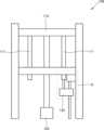
도 1은 본 발명의 일 실시예에 따른 삼차원 프린팅 장치(1000)의 프린팅부(100)를 개략적으로 나타낸 사시도고 도 2는 이를 측면에서 바라본 측면도이다. 먼저, 도 1에 도시된 바와 같이, 프린팅부(100)는, 스테이지부(110), 스테이지 이동부(120) 및, 변위 센서부(130)를 포함할 수 있다. 스테이지부(110)는 프린팅부(100)의 내부에 설치되어 스테이지 이동부(120)에 의해 상하 방향으로 이동될 수 있고, 변위 센서부(130)는 스테이지부(110)의 이동과 연동하여 스테이지부(110)의 변위를 측정할 수 있다.FIG. 1 is a perspective view schematically showing a printing unit (100) of a three-dimensional printing device (1000) according to one embodiment of the present invention, and FIG. 2 is a side view thereof. First, as shown in FIG. 1, the printing unit (100) may include a stage unit (110), a stage moving unit (120), and a displacement sensor unit (130). The stage unit (110) may be installed inside the printing unit (100) and may be moved up and down by the stage moving unit (120), and the displacement sensor unit (130) may measure the displacement of the stage unit (110) in conjunction with the movement of the stage unit (110).
스테이지 이동부(120)는 모터의 회전 운동을 직선 왕복 운동으로 변환하기 위한 볼 스크류일수 있으며, 리니어 모터 가이드 레일, 체인 레일, 벨트 레일, 또는 래크와 피니언이거나, 선형으로 신장 또는 수축할 수 있는 일종의 선형 구동체로서, 유압 실린더나, 공압 실린더나, 전동 실린더 중 어느 하나의 실린더 구동체들 직선 운동을 위한 다양한 기계 요소가 적용될 수 있다.The stage moving part (120) may be a ball screw for converting the rotational motion of the motor into a linear reciprocating motion, a linear motor guide rail, a chain rail, a belt rail, or a rack and pinion, or a type of linear actuator that can linearly extend or contract, and various mechanical elements for linear motion, such as a hydraulic cylinder, a pneumatic cylinder, or an electric cylinder, may be applied.
또한, 도 2에 도시된 바와 같이, 스테이지부(110)는 스테이지 이동부(120)에 따른 승하강을 안내할 수 있도록 스테이지부(110)의 일면으로부터 연장되는 형상으로 형성되어 스테이지부(110)의 승하강을 안내하며 연동되어 승하강되는 가이드부(111)를 포함할 수 있다. 가이드부(111)는 전체적으로 막대 형상으로 형성되어 스테이지부(110)의 하면에 복수개가 설치될 수 있다.In addition, as illustrated in FIG. 2, the stage unit (110) may include a guide unit (111) that is formed in a shape extending from one side of the stage unit (110) to guide the raising and lowering of the stage unit (110) and is linked to the raising and lowering. The guide unit (111) may be formed in a rod shape overall and a plurality of units may be installed on the lower surface of the stage unit (110).
또한, 변위 센서부(130)는, 스테이지부(110)의 일면으로부터 소정의 간격만큼 이격된 위치에 설치되어 스테이지부(110)의 변위를 접촉식으로 측정할 수 있다. 변위 센서부(130)는, 예컨대, 일단에 측정 대상 물체와 접촉하여 변위되는 프로브 팁을 포함하고, 내부에 구비된 기계장치들을 통해 측정 대상 물체의 변위를 측정할 수 있다.In addition, the displacement sensor unit (130) is installed at a position spaced apart from one surface of the stage unit (110) by a predetermined distance and can measure the displacement of the stage unit (110) in a contact manner. The displacement sensor unit (130) includes, for example, a probe tip that comes into contact with a measurement target object at one end and is displaced, and can measure the displacement of the measurement target object through mechanical devices provided therein.
또한, 예컨대, 변위 센서부(130)는, 10mm 내지 30mm의 측정 길이와 1μm 이하의 측정 정밀도를 갖거나, 100mm의 측정 길이와 1μm 내지 2μm의 측정 정밀도를 갖는 고정밀 접촉식 변위 센서인 LVDT(Linear Variable Displacement Transducer, 선형 가변 변위 변환기) 센서일 수 있다.In addition, for example, the displacement sensor unit (130) may be a high-precision contact-type displacement sensor, an LVDT (Linear Variable Displacement Transducer) sensor, which has a measurement length of 10 mm to 30 mm and a measurement precision of 1 μm or less, or a measurement length of 100 mm and a measurement precision of 1 μm to 2 μm.
그러나, 3D 프린터는 일반적으로 스테이지의 적층 높이가 250mm 내지 300mm이며 대면적 3D 프린팅 장비의 경우 적층 높이가 최대 500mm 사양을 갖기 때문에, 100mm 이하의 측정 길이를 갖는 고정밀도의 접촉식 변위 측정 센서를 적용하는데 한계가 있다.However, since 3D printers generally have a stacking height of 250 mm to 300 mm on the stage, and large-area 3D printing equipment has a stacking height specification of up to 500 mm, there is a limit to applying a high-precision contact-type displacement measurement sensor with a measurement length of 100 mm or less.
이에 따라, 도 3 내지 도 5를 참조하여, 짧은 측정 길이를 갖는 고정밀도의 접촉식 변위 측정 센서를 활용할 수 있도록 하는 본원발명의 구성 요소들과 이들의 동작 과정을 설명하도록 한다.Accordingly, with reference to FIGS. 3 to 5, the components of the present invention and their operation processes that enable the use of a high-precision contact-type displacement measurement sensor having a short measurement length will be described.
먼저, 도 3은 도 2의 A 영역을 확대한 부분확대도이다. 도 3에 도시된 바와 같이, 변위 센서부(130)는, 스테이지부(110) 일면으로부터 소정의 간격만큼 이격된 위치에 설치되어 스테이지부(110)의 변위를 접촉식으로 측정하는 접촉 센서부(131)와, 스테이지부(110)의 하강에 따른 변위를 측정할 수 있도록, 접촉 센서부(131)를 스테이지부(110)의 이동 방향과 대응되는 방향으로 이동시키는 센서 이동부(132)를 포함할 수 있다. 센서 이동부(132)는, 스테이지 이동부(120)와 마찬가지로 볼 스크류 등 모터의 회전 운동을 직선 왕복 운동으로 변환하기 위한 장치가 적용될 수 있다.First, FIG. 3 is a partial enlarged view of area A of FIG. 2. As illustrated in FIG. 3, the displacement sensor unit (130) may include a contact sensor unit (131) that is installed at a position spaced apart from one surface of the stage unit (110) by a predetermined distance and contact-wise measures the displacement of the stage unit (110), and a sensor moving unit (132) that moves the contact sensor unit (131) in a direction corresponding to the moving direction of the stage unit (110) so as to measure the displacement according to the lowering of the stage unit (110). The sensor moving unit (132), like the stage moving unit (120), may be applied with a device for converting the rotational motion of a motor, such as a ball screw, into a linear reciprocating motion.
이때, 스테이지부(110)는 초기 소수의 레이어들의 적층을 위한 예열이나 분말, 모재 등의 용융을 위해 조사되는 레이저 또는, 출력물의 잔류 응력 제거를 위한 고온 환경 등 고온으로 갈 수록 스테이지부(110)의 Z축 즉, 승하강 제어 정밀도가 낮아지게 되는 현상이 발생한다.At this time, the stage part (110) experiences a phenomenon in which the Z-axis, i.e., the elevation control precision of the stage part (110) decreases as the temperature increases due to a laser irradiation for preheating for laminating a small number of initial layers or melting of powder, base material, etc., or a high-temperature environment for removing residual stress from the output.
이에 따라, 스테이지부(110)는 가이드부(111)의 일단에 설치되는 단열부(112)를 더 포함하고, 접촉 센서부(131)는 접촉 센서부(131)의 일단이 단열부(112)와 접촉되도록 스테이지부(110)의 일측에 설치될 수 있다. 그러나, 단열부(112)는 이에 한정되지 않고 접촉 센서부(131)의 설치 위치에 따라 단열부(112)는 스테이지부(110)에 직접 설치되는 것 또한 가능하다.Accordingly, the stage part (110) further includes an insulation part (112) installed at one end of the guide part (111), and the contact sensor part (131) may be installed at one side of the stage part (110) so that one end of the contact sensor part (131) comes into contact with the insulation part (112). However, the insulation part (112) is not limited thereto, and depending on the installation position of the contact sensor part (131), the insulation part (112) may also be installed directly on the stage part (110).
이어서, 도 4에 도시된 바와 같이, 1층의 레이어가 적층 완료되어 다음 레이어를 적층할 수 있도록 스테이지 이동부(120)에 의해 스테이지부(110)가 하강하면 접촉 센서부(131)의 일측을 가압하여 접촉식으로 스테이지부(110)의 변위를 측정하게 된다.Next, as shown in Fig. 4, when the first layer is completed and the next layer can be stacked, the stage part (110) is lowered by the stage moving part (120), and one side of the contact sensor part (131) is pressed to measure the displacement of the stage part (110) in a contact manner.
그 이후, 도 5에 도시된 바와 같이, 접촉 센서부(131)는 스테이지부(110)의 변위를 반복하여 측정할 수 있도록 센서 이동부(132)에 의해 하강하게 된다. 접촉 센서부(131)의 하강 거리는 스테이지부(110)의 하강 거리와 동일한 거리일 수 있으며, 도 5의 상태에서 스테이지부(110)의 변위 측정을 위한 접촉 센서부(131)의 원점 초기화 및 재설정이 이루어질 수 있다.Thereafter, as shown in FIG. 5, the contact sensor unit (131) is lowered by the sensor moving unit (132) so that the displacement of the stage unit (110) can be repeatedly measured. The lowering distance of the contact sensor unit (131) may be the same distance as the lowering distance of the stage unit (110), and in the state of FIG. 5, the origin initialization and reset of the contact sensor unit (131) for measuring the displacement of the stage unit (110) may be performed.
또한, 본 발명의 일 실시예에 따른 삼차원 프린팅 장치(1000)는, 도 6에 도시한 바와 같이, 접촉 센서부(131)로부터 스테이지부(110)의 변위 정보를 인가받아, 스테이지 이동부(120) 또는 센서 이동부(132)에 구동 제어 신호를 인가하는 제어부(140)을 포함할 수 있다.In addition, the three-dimensional printing device (1000) according to one embodiment of the present invention may include a control unit (140) that receives displacement information of the stage unit (110) from the contact sensor unit (131) and applies a driving control signal to the stage moving unit (120) or the sensor moving unit (132), as illustrated in FIG. 6.
보다 구체적으로, 제어부(140)는, 스테이지 이동부(120)에 스테이지 하강 제어 신호를 인가하여 스테이지부(110)가 하강한 제 1 거리와, 접촉 센서부(131)로부터 측정된 스테이지부(110)의 제 2 거리를 비교하여, 제 1 거리와 제 2 거리의 차이값이 기 설정된 소정의 오차 범위 이내일 경우, 이를 정상 상태로 판별하여 접촉 센서부(131)가 제 1 거리만큼 하강할 수 있도록 센서 이동부(132)에 센서 하강 제어 신호를 인가할 수 있다.More specifically, the control unit (140) compares a first distance by which the stage unit (110) has descended by applying a stage lowering control signal to the stage moving unit (120) and a second distance of the stage unit (110) measured from the contact sensor unit (131), and if the difference between the first distance and the second distance is within a predetermined error range, determines this to be a normal state and applies a sensor lowering control signal to the sensor moving unit (132) so that the contact sensor unit (131) can descend by the first distance.
또한, 제어부(140)는, 스테이지 이동부(120)에 스테이지 하강 제어 신호를 인가하여 스테이지부(110)가 하강한 제 1 거리와, 접촉 센서부(131)로부터 측정된 스테이지부(110)의 제 2 거리를 비교하여, 제 1 거리와 제 2 거리의 차이값이 기 설정된 소정의 오차 범위를 벗어날 경우, 이를 비정상 상태로 판별하여 접촉 센서부(131)가 차이값만큼 하강할 수 있도록 센서 이동부(132)에 스테이지 보정 하강 제어 신호를 인가할 수 있다. 접촉 센서부(131)가 차이값만큼 하강하여 보정된 뒤에는 제 1 거리만큼 하강하게 될 수 있다.In addition, the control unit (140) compares the first distance by which the stage unit (110) has descended by applying a stage lowering control signal to the stage moving unit (120) and the second distance of the stage unit (110) measured from the contact sensor unit (131), and if the difference between the first distance and the second distance is outside a predetermined error range, determines this to be an abnormal state and applies a stage correction lowering control signal to the sensor moving unit (132) so that the contact sensor unit (131) can descend by the difference value. After the contact sensor unit (131) has descended by the difference value and has been corrected, it can descend by the first distance.
이하에서는 도 7을 참조하여 삼차원 조형물의 적층 제조를 위한 본 발명의 일 실시예에 따른 삼차원 프린팅 장치(1000)의 추가 구성요소들을 설명하도록 한다.Hereinafter, additional components of a three-dimensional printing device (1000) according to one embodiment of the present invention for laminated manufacturing of a three-dimensional object will be described with reference to FIG. 7.
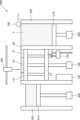
도 7에 도시된 바와 같이, 본 발명의 일 실시예에 따른 삼차원 프린팅 장치(1000)는 프린팅부(100)에 분말(P)을 공급하여 분말층(P1)을 형성하는 분말 공급부(200), 분말층(P1)의 적어도 일부가 용융되어 결합된 분말 결합층(P2)이 형성될 수 있도록, 분말층(P1)을 향해 선택적으로 레이저를 조사하는 레이저 헤드부(300) 및, 스테이지부(110)의 잔여 분말을 회수하는 분말 회수부(400)를 포함할 수 있다.As illustrated in FIG. 7, a three-dimensional printing device (1000) according to one embodiment of the present invention may include a powder supply unit (200) that supplies powder (P) to a printing unit (100) to form a powder layer (P1), a laser head unit (300) that selectively irradiates a laser toward the powder layer (P1) so that a powder bonding layer (P2) is formed by melting at least a portion of the powder layer (P1), and a powder recovery unit (400) that recovers residual powder from the stage unit (110).
보다 구체적으로, 분말 공급부(200)는, 프린팅부(100)에 분말(P)을 공급할 수 있도록 프린팅부(100)의 일측면에 설치될 수 있고, 분말 공급부(200)의 내부에 수용된 분말(P)을 지지하는 공급 스테이지부(210), 분말(P)이 상방으로 공급될 수 있도록 공급 스테이지부(210)를 상하 방향으로 이동시키는 공급 스테이지 이동부(220) 및, 상방으로 이동된 분말(P)을 스테이지부(110)를 향하는 방향으로 밀어내어 스테이지부(110)로 공급하는 리코터(230)를 포함할 수 있다.More specifically, the powder supply unit (200) can be installed on one side of the printing unit (100) so as to supply powder (P) to the printing unit (100), and can include a supply stage unit (210) that supports powder (P) accommodated inside the powder supply unit (200), a supply stage moving unit (220) that moves the supply stage unit (210) in a vertical direction so that the powder (P) can be supplied upward, and a recoater (230) that pushes the powder (P) that has been moved upward in a direction toward the stage unit (110) and supplies it to the stage unit (110).
또한, 분말 회수부(400)는, 스테이지부(110)에 분말층(P1)을 형성하고 남은 잔여 분말을 회수할 수 있도록 프린팅부(100)의 타측면에 설치될 수 있고, 잔여 분말을 회수하여 보관할 수 있도록 회수된 잔여 분말을 지지하는 회수 스테이지부(410) 및, 회수 스테이지부(410)를 상하 방향으로 이동시키는 회수 스테이지 이동부(420)를 포함할 수 있다.In addition, the powder recovery unit (400) may be installed on the other side of the printing unit (100) so as to form a powder layer (P1) on the stage unit (110) and recover the remaining residual powder, and may include a recovery stage unit (410) that supports the recovered residual powder so as to recover and store the remaining powder, and a recovery stage moving unit (420) that moves the recovery stage unit (410) in the up and down direction.
즉, 본 발명의 일 실시예에 따른 삼차원 프린팅 장치(1000)는, PBF(Powder Bed Fusion) 방식의 3D 프린팅 장치일 수 있다. 그러나, 삼차원 프린팅 장치(1000)는 여기에 한정되지 않고 삼차원 조형물의 적층 제조를 위해 스테이지를 하강시키며 적층이 진행되는 다양한 방식의 3D 프린팅 장치일 수도 있다.That is, the three-dimensional printing device (1000) according to one embodiment of the present invention may be a 3D printing device using the PBF (Powder Bed Fusion) method. However, the three-dimensional printing device (1000) is not limited thereto, and may be a 3D printing device using various methods in which a stage is lowered and lamination is performed for lamination manufacturing of a three-dimensional object.
이하에서는 도 8 내지 도 10을 참조하여 본 발명의 일 실시예에 따른 삼차원 프린팅 방법을 설명하도록 한다.Hereinafter, a three-dimensional printing method according to one embodiment of the present invention will be described with reference to FIGS. 8 to 10.
도 8에 도시된 바와 같이, 본 발명의 일 실시예에 따른 삼차원 프린팅 방법은, (a) 프린팅부의 내부에 배치되는 스테이지부를 제 1 거리만큼 하강시키는 단계, (b) 스테이지부의 이동과 연동되는 접촉식 변위 센서를 이용하여 스테이지부의 변위를 측정하는 단계, (c) 접촉식 변위 센서의 측정값인 제 2 거리와 제 1 거리를 비교하여 스테이지부의 위치를 보정하는 단계, (d) 접촉식 변위 센서를 제 1 거리만큼 하강시키는 단계 및, (e) 삼차원 조형물이 적층 제조될 수 있도록, (a) 내지 (d)단계를 복수회 반복하는 단계를 포함할 수 있다.As illustrated in FIG. 8, a three-dimensional printing method according to an embodiment of the present invention may include: (a) a step of lowering a stage portion disposed inside a printing portion by a first distance, (b) a step of measuring a displacement of the stage portion using a contact-type displacement sensor linked to the movement of the stage portion, (c) a step of correcting a position of the stage portion by comparing a second distance, which is a measurement value of the contact-type displacement sensor, with a first distance, (d) a step of lowering the contact-type displacement sensor by the first distance, and (e) a step of repeating steps (a) to (d) multiple times so that a three-dimensional object can be laminated.
보다 구체적으로, 도 9에 도시된 바와 같이, 스테이지부의 위치를 보정하는 (c) 단계는, (c1) 제 1 거리와 제 2 거리의 차이값이 기 설정된 소정의 오차 범위 이내일 경우, 이를 정상 상태로 판별하는 단계 및, (c2) 제 1 거리와 제 2 거리의 차이값이 기 설정된 소정의 오차 범위를 벗어날 경우, 이를 비정상 상태로 판별하여 스테이지부를 차이값만큼 하강시키는 단계를 포함할 수 있다.More specifically, as illustrated in FIG. 9, step (c) of correcting the position of the stage unit may include a step of (c1) determining that the difference between the first distance and the second distance is within a predetermined error range, as a normal state, and a step of (c2) determining that the difference between the first distance and the second distance is outside the predetermined error range, as an abnormal state, and lowering the stage unit by the amount of the difference.
이러한 본 발명의 일 실시예에 따른 삼차원 프린팅 방법에 의한 도 10을 참조하여 설명하도록 한다.A three-dimensional printing method according to one embodiment of the present invention will be described with reference to FIG. 10.
도 10에 도시된 바와 같이, 조형물의 삼차원 적층 제조를 위한 레이어 두께를 제 1 거리(t)로 설정하고 적층이 시작되면 접촉식 변위 센서의 원점을 초기화한다. 이후 스테이지부를 제 1 거리(t)만큼 하강시킨 후 접촉식 변위 센서의 측정값과 제 1 거리(t)의 차이값이 기 설정된 오차범위, 예컨대 1μm 이내를 벗어날 경우 이 차이값을 반영하여 스테이지부의 높이를 조절하고, 오차범위 이내일 경우 스테이지부상에 분말을 도포하여 코팅한 뒤 레이저 스캐닝으로 분말 결합층을 형성하며, 위 과정을 복수회 반복하여 최종 제품을 제조할 수 있다.As illustrated in Fig. 10, the layer thickness for three-dimensional laminated manufacturing of a model is set to a first distance (t), and when lamination begins, the origin of the contact-type displacement sensor is initialized. Thereafter, the stage is lowered by the first distance (t), and if the difference between the measured value of the contact-type displacement sensor and the first distance (t) is outside a preset error range, for example, within 1 μm, the height of the stage is adjusted by reflecting this difference value, and if it is within the error range, powder is applied on the stage to coat it, and then a powder bonding layer is formed by laser scanning. The above process is repeated multiple times to manufacture a final product.
따라서, 본 발명의 일 실시예에 따른 삼차원 프린팅 장치 및 삼차원 프린팅 방법에 따르면, 짧은 측정 길이를 갖는 고정밀도의 접촉식 변위 측정 센서를 스테이지부의 이동과 연동하여 상하 구동시킴으로써 스테이지의 변위를 정밀하게 측정 및 제어할 수 있고, 고온의 적층 환경에서 스테이지의 승하강 제어 정밀도를 향상시킬 수 있으며, PBF(Powder Bed Fusion) 방식이나 DED(Direct, Energy Deposition)방식 등 다양한 3D 프린팅 장치에도 적용이 가능하다.Therefore, according to the three-dimensional printing device and three-dimensional printing method according to one embodiment of the present invention, the displacement of the stage can be precisely measured and controlled by driving a high-precision contact-type displacement measuring sensor with a short measurement length up and down in conjunction with the movement of the stage, and the precision of the stage raising and lowering control in a high-temperature lamination environment can be improved, and it can be applied to various 3D printing devices such as the PBF (Powder Bed Fusion) method and the DED (Direct, Energy Deposition) method.
본 발명은 도면에 도시된 실시예를 참고로 설명되었으나 이는 예시적인 것에 불과하며, 당해 기술분야에서 통상의 지식을 가진 자라면 이로부터 다양한 변형 및 균등한 다른 실시예가 가능하다는 점을 이해할 것이다. 따라서 본 발명의 진정한 기술적 보호 범위는 첨부된 특허청구범위의 기술적 사상에 의하여 정해져야 할 것이다.Although the present invention has been described with reference to the embodiments shown in the drawings, these are merely exemplary, and those skilled in the art will understand that various modifications and equivalent other embodiments are possible therefrom. Therefore, the true technical protection scope of the present invention should be determined by the technical idea of the appended claims.
1000: 삼차원 프린팅 장치
100: 프린팅부
110: 스테이지부
111: 가이드부
112: 단열부
120: 스테이지 이동부
130: 변위 센서부
131: 접촉 센서부
132: 센서 이동부
140: 제어부
200: 분말 공급부
210: 공급 스테이지부
220: 공급 스테이지 이동부
300: 레이저 헤드부
400: 분말 회수부
410: 회수 스테이지부
420: 회수 스테이지 이동부
P: 분말
P1: 분말층
P2: 분말 결합층1000: 3D Printing Device
100: Printing Department
110: Stage section
111: Guide Department
112: Insulation
120: Stage moving part
130: Displacement sensor section
131: Contact sensor section
132: Sensor moving part
140: Control Unit
200: Powder supply section
210: Supply stage section
220: Supply stage moving part
300: Laser head
400: Powder recovery unit
410: Recovery stage section
420: Recovery stage moving part
P: Powder
P1: Powder layer
P2: Powder bonding layer
Claims (12)
Translated fromKorean상기 프린팅부의 내부에 배치되는 스테이지부;
상기 스테이지부를 상하 방향으로 이동시키는 스테이지 이동부; 및
상기 스테이지부의 이동과 연동하여 상기 스테이지부의 변위를 측정하는 변위 센서부;
를 포함하는, 삼차원 프린팅 장치.A printing section where three-dimensional objects are manufactured in layers;
A stage section placed inside the above printing section;
A stage moving unit that moves the stage unit in the up and down direction; and
A displacement sensor unit that measures the displacement of the stage unit in conjunction with the movement of the stage unit;
A three-dimensional printing device comprising:
상기 변위 센서부는,
상기 스테이지부의 일면으로부터 소정의 간격만큼 이격된 위치에 설치되어 상기 스테이지부의 변위를 접촉식으로 측정하는 접촉 센서부;
를 포함하는, 삼차원 프린팅 장치.In paragraph 1,
The above displacement sensor part,
A contact sensor unit installed at a position spaced apart from one surface of the stage unit by a predetermined distance and measuring the displacement of the stage unit by contact;
A three-dimensional printing device comprising:
상기 변위 센서부는,
상기 스테이지부의 하강에 따른 변위를 측정할 수 있도록, 상기 접촉 센서부를 상기 스테이지부의 이동 방향과 대응되는 방향으로 이동시키는 센서 이동부;
를 포함하는, 삼차원 프린팅 장치.In the second paragraph,
The above displacement sensor part,
A sensor moving unit that moves the contact sensor unit in a direction corresponding to the moving direction of the stage unit so as to measure displacement according to the lowering of the stage unit;
A three-dimensional printing device comprising:
상기 스테이지부는,
상기 스테이지부의 승하강을 안내할 수 있도록 상기 스테이지부의 일면으로부터 연장되는 형상으로 형성되어 상기 스테이지부의 이동과 연동되어 승하강되는 가이드부;
를 포함하는, 삼차원 프린팅 장치.In the third paragraph,
The above stage section,
A guide part formed in a shape extending from one side of the stage part so as to guide the raising and lowering of the stage part and raised and lowered in conjunction with the movement of the stage part;
A three-dimensional printing device comprising:
상기 스테이지부는,
상기 스테이지부의 일면 또는 상기 가이드부의 일단에 설치되는 단열부; 를 더 포함하고,
상기 접촉 센서는,
상기 접촉 센서의 일단이 상기 단열부와 접촉되도록 상기 스테이지부의 일측에 설치되는, 삼차원 프린팅 장치.In paragraph 4,
The above stage section,
Further comprising an insulating member installed on one side of the stage section or one end of the guide section;
The above contact sensor,
A three-dimensional printing device, wherein one end of the contact sensor is installed on one side of the stage portion so that it comes into contact with the insulating portion.
상기 프린팅부에 분말을 공급하여 분말층을 형성하는 분말 공급부;
상기 분말층의 적어도 일부가 용융되어 결합된 분말 결합층이 형성될 수 있도록, 상기 분말층을 향해 선택적으로 레이저를 조사하는 레이저 헤드부; 및
상기 스테이지부의 잔여 분말을 회수하는 분말 회수부;
를 더 포함하는, 삼차원 프린팅 장치.In paragraph 1,
A powder supply unit that supplies powder to the above printing unit to form a powder layer;
A laser head section selectively irradiating a laser toward the powder layer so that at least a portion of the powder layer is melted and a combined powder bonding layer is formed; and
A powder recovery unit for recovering residual powder from the above stage unit;
A three-dimensional printing device further comprising:
상기 접촉 센서로부터 상기 스테이지부의 변위 정보를 인가받아, 상기 스테이지 이동부 또는 상기 센서 이동부에 구동 제어 신호를 인가하는 제어부;
를 더 포함하는, 삼차원 프린팅 장치.In the third paragraph,
A control unit that receives displacement information of the stage unit from the contact sensor and applies a drive control signal to the stage moving unit or the sensor moving unit;
A three-dimensional printing device further comprising:
상기 제어부는,
상기 스테이지 이동부에 스테이지 하강 제어 신호를 인가하여 상기 스테이지부가 하강한 제 1 거리와, 상기 접촉 센서부로부터 측정된 상기 스테이지부의 제 2 거리를 비교하여, 상기 제 1 거리와 상기 제 2 거리의 차이값이 기 설정된 소정의 오차 범위 이내일 경우, 이를 정상 상태로 판별하여 상기 접촉 센서부가 상기 제 1 거리만큼 하강할 수 있도록 상기 센서 이동부에 센서 하강 제어 신호를 인가하는, 삼차원 프린팅 장치.In paragraph 7,
The above control unit,
A three-dimensional printing device that applies a stage lowering control signal to the stage moving unit, compares a first distance by which the stage unit has been lowered with a second distance of the stage unit measured from the contact sensor unit, and determines that the difference between the first distance and the second distance is within a preset error range, thereby determining this as a normal state and applying a sensor lowering control signal to the sensor moving unit so that the contact sensor unit can be lowered by the first distance.
상기 제어부는,
상기 스테이지 이동부에 스테이지 하강 제어 신호를 인가하여 상기 스테이지가 하강한 제 1 거리와, 상기 접촉 센서로부터 측정된 상기 스테이지부의 제 2 거리를 비교하여, 상기 제 1 거리와 상기 제 2 거리의 차이값이 기 설정된 소정의 오차 범위를 벗어날 경우, 이를 비정상 상태로 판별하여 상기 스테이지부가 상기 상기 차이값만큼 하강할 수 있도록 상기 스테이지 이동부에 스테이지 보정 하강 제어 신호를 인가하는, 삼차원 프린팅 장치.In paragraph 7,
The above control unit,
A three-dimensional printing device that applies a stage lowering control signal to the stage moving unit, compares a first distance by which the stage has been lowered with a second distance of the stage unit measured from the contact sensor, and determines that the difference between the first distance and the second distance is outside a preset error range, thereby determining this as an abnormal state and applying a stage correction lowering control signal to the stage moving unit so that the stage unit can be lowered by the amount of the difference.
(b) 상기 스테이지부의 이동과 연동되는 접촉식 변위 센서를 이용하여 상기 스테이지부의 변위를 측정하는 단계;
(c) 상기 접촉식 변위 센서의 측정값인 제 2 거리와 상기 제 1 거리를 비교하여 상기 스테이지부의 위치를 보정하는 단계;
(d) 상기 접촉식 변위 센서를 상기 제 1 거리만큼 하강시키는 단계; 및
(e) 삼차원 조형물이 적층 제조될 수 있도록, 상기 (a) 내지 (d)단계를 복수회 반복하는 단계;
삼차원 프린팅 방법.(a) a step of lowering a stage portion positioned inside a printing portion by a first distance;
(b) a step of measuring the displacement of the stage portion using a contact displacement sensor linked to the movement of the stage portion;
(c) a step of correcting the position of the stage portion by comparing the second distance, which is a measurement value of the contact-type displacement sensor, with the first distance;
(d) a step of lowering the contact displacement sensor by the first distance; and
(e) a step of repeating steps (a) to (d) multiple times so that a three-dimensional object can be laminated;
3D printing method.
상기 (c) 단계는,
(c1) 상기 제 1 거리와 상기 제 2 거리의 차이값이 기 설정된 소정의 오차 범위 이내일 경우, 이를 정상 상태로 판별하는 단계;
를 포함하는, 삼차원 프린팅 방법.In Article 10,
Step (c) above,
(c1) a step of determining that the difference between the first distance and the second distance is within a preset error range, as a normal state;
A three-dimensional printing method comprising:
상기 (c) 단계는,
(c2) 상기 제 1 거리와 상기 제 2 거리의 차이값이 기 설정된 소정의 오차 범위를 벗어날 경우, 이를 비정상 상태로 판별하여 상기 스테이지부를 상기 차이값만큼 하강시키는 단계;
를 포함하는, 삼차원 프린팅 방법.In Article 10,
Step (c) above,
(c2) a step of determining that the difference between the first distance and the second distance is outside a preset error range and lowering the stage by the difference value by determining that this is an abnormal state;
A three-dimensional printing method comprising:
Priority Applications (1)
| Application Number | Priority Date | Filing Date | Title |
|---|---|---|---|
| KR1020230153844AKR20250067581A (en) | 2023-11-08 | 2023-11-08 | Three-dimension printing device and method |
Applications Claiming Priority (1)
| Application Number | Priority Date | Filing Date | Title |
|---|---|---|---|
| KR1020230153844AKR20250067581A (en) | 2023-11-08 | 2023-11-08 | Three-dimension printing device and method |
Publications (1)
| Publication Number | Publication Date |
|---|---|
| KR20250067581Atrue KR20250067581A (en) | 2025-05-15 |
Family
ID=95706737
Family Applications (1)
| Application Number | Title | Priority Date | Filing Date |
|---|---|---|---|
| KR1020230153844APendingKR20250067581A (en) | 2023-11-08 | 2023-11-08 | Three-dimension printing device and method |
Country Status (1)
| Country | Link |
|---|---|
| KR (1) | KR20250067581A (en) |
- 2023
- 2023-11-08KRKR1020230153844Apatent/KR20250067581A/enactivePending
Similar Documents
| Publication | Publication Date | Title |
|---|---|---|
| US8153183B2 (en) | Adjustable platform assembly for digital manufacturing system | |
| EP2319641B1 (en) | Method to apply multiple materials with selective laser melting on a 3D article | |
| EP0523981B1 (en) | Method of making electronic packages and smart structures formed by thermal spray deposition | |
| US20190184631A1 (en) | Method and Arrangement for Producing A Workpiece by Using Additive Manufacturing Techniques | |
| CN109420762B (en) | 3D printing device and method | |
| EP2869983B1 (en) | A laser sintering technique for manufacturing items on a movable sintering platform | |
| US10155346B1 (en) | Calibration system and method for determination of relative position of two components in multi-axis motion system | |
| JP5895172B2 (en) | Manufacturing method of three-dimensional shaped object | |
| EP3684593B1 (en) | Build platform guiding arrangement for an addititive manufacturing apparatus | |
| JP2009532243A (en) | Automatic end calibration in extrusion equipment. | |
| US20240216993A1 (en) | Support Arrangement for Additive Manufacturing, Additive Manufacturing Device and Method of Producing Three-Dimensional Object | |
| WO2021054894A1 (en) | Apparatus for automated additive manufacturing of a three dimensional object and a method thereof | |
| US20150079217A1 (en) | Device for Printing Simultaneously Three Dimensional Objects | |
| CN106624826A (en) | Micro-plasma 3D printing and milling combined processing device and method | |
| JP2020132937A (en) | Production method and three-dimensional molding device | |
| EP3395550B1 (en) | Three-dimensional object shaping device and manufacturing method | |
| KR20250067581A (en) | Three-dimension printing device and method | |
| CA3003207A1 (en) | Apparatus and method for the production of a three-dimensional metallic shaped body | |
| KR102476579B1 (en) | Printer for manufacturing three-dimensional object | |
| JP7171466B2 (en) | Manufacturing method, three-dimensional modeling apparatus | |
| JP6878364B2 (en) | Movable wall for additional powder floor | |
| WO2004011177A2 (en) | Building a three-dimensional structure by manipulating individual particles | |
| JP4141379B2 (en) | Method and apparatus for modeling a three-dimensional object | |
| CN217344000U (en) | Laser welding system | |
| JP7124659B2 (en) | Additive manufacturing equipment |
Legal Events
| Date | Code | Title | Description |
|---|---|---|---|
| PA0109 | Patent application | Patent event code:PA01091R01D Comment text:Patent Application Patent event date:20231108 | |
| PA0201 | Request for examination | Patent event code:PA02011R01I Patent event date:20231108 Comment text:Patent Application | |
| PG1501 | Laying open of application |