KR20250065682A - Multipath optical devices - Google Patents
Multipath optical devicesDownload PDFInfo
- Publication number
- KR20250065682A KR20250065682AKR1020257011528AKR20257011528AKR20250065682AKR 20250065682 AKR20250065682 AKR 20250065682AKR 1020257011528 AKR1020257011528 AKR 1020257011528AKR 20257011528 AKR20257011528 AKR 20257011528AKR 20250065682 AKR20250065682 AKR 20250065682A
- Authority
- KR
- South Korea
- Prior art keywords
- doe
- input
- waveguide
- grating
- optical device
- Prior art date
- Legal status (The legal status is an assumption and is not a legal conclusion. Google has not performed a legal analysis and makes no representation as to the accuracy of the status listed.)
- Pending
Links
Images


Classifications
- G—PHYSICS
- G02—OPTICS
- G02B—OPTICAL ELEMENTS, SYSTEMS OR APPARATUS
- G02B5/00—Optical elements other than lenses
- G02B5/18—Diffraction gratings
- G02B5/1876—Diffractive Fresnel lenses; Zone plates; Kinoforms
- G02B5/189—Structurally combined with optical elements not having diffractive power
- G—PHYSICS
- G02—OPTICS
- G02B—OPTICAL ELEMENTS, SYSTEMS OR APPARATUS
- G02B27/00—Optical systems or apparatus not provided for by any of the groups G02B1/00 - G02B26/00, G02B30/00
- G02B27/0081—Optical systems or apparatus not provided for by any of the groups G02B1/00 - G02B26/00, G02B30/00 with means for altering, e.g. enlarging, the entrance or exit pupil
- G—PHYSICS
- G02—OPTICS
- G02B—OPTICAL ELEMENTS, SYSTEMS OR APPARATUS
- G02B27/00—Optical systems or apparatus not provided for by any of the groups G02B1/00 - G02B26/00, G02B30/00
- G02B27/01—Head-up displays
- G02B27/017—Head mounted
- G02B27/0172—Head mounted characterised by optical features
- G—PHYSICS
- G02—OPTICS
- G02B—OPTICAL ELEMENTS, SYSTEMS OR APPARATUS
- G02B5/00—Optical elements other than lenses
- G02B5/18—Diffraction gratings
- G02B5/1814—Diffraction gratings structurally combined with one or more further optical elements, e.g. lenses, mirrors, prisms or other diffraction gratings
- G02B5/1819—Plural gratings positioned on the same surface, e.g. array of gratings
Landscapes
- Physics & Mathematics (AREA)
- General Physics & Mathematics (AREA)
- Optics & Photonics (AREA)
- Diffracting Gratings Or Hologram Optical Elements (AREA)
Abstract
Translated fromKorean
Description
Translated fromKorean본 개시내용은 증강 현실 또는 가상 현실 디스플레이들과 같은 디스플레이들에서 사용하기에 적합한 광학 디바이스들에 관한 것이다. 이러한 광학 디바이스들은 일반적으로 도파관, 및 도파관 안팎으로 광을 결합하기 위한 회절 광학 요소들을 포함한다. 가상 현실 및 증강 현실 디스플레이들은 안경, 비디오 게임들을 위한 디스플레이들, 및 군사 또는 교통 애플리케이션들을 위한 스크린들과 같은 웨어러블 디바이스들을 포함한다.The present disclosure relates to optical devices suitable for use in displays, such as augmented reality or virtual reality displays. Such optical devices generally include a waveguide and diffractive optical elements for coupling light into and out of the waveguide. Virtual reality and augmented reality displays include wearable devices, such as glasses, displays for video games, and screens for military or transportation applications.
종래의 증강 현실 디스플레이에서, 투명 디스플레이 스크린은 사용자가 물리적 세계를 계속 볼 수 있도록 사용자의 전방에 제공된다. 디스플레이 스크린은 유리 도파관일 수 있고, 프로젝터는 도파관의 일 표면에 제공된다. 디스플레이 스크린은, 예를 들어, 한 쌍의 안경알 또는 차량 상의 윈도우에 제공될 수 있다. 프로젝터로부터의 광은 입력 회절 격자에 의해 도파관 내로 결합된다. 투영된 광은 도파관 내에서 내부 전반사된다. 그 다음, 광은 다른 회절 격자에 의해 도파관 밖으로 결합되어 사용자가 볼 수 있다. 프로젝터는 물리적 세계의 사용자의 뷰를 증강시키는 정보 및/또는 이미지들을 제공할 수 있다.In a conventional augmented reality display, a transparent display screen is provided in front of the user so that the user can continue to view the physical world. The display screen may be a glass waveguide, and a projector is provided on one surface of the waveguide. The display screen may be provided, for example, in a pair of eyeglasses or a window on a vehicle. Light from the projector is coupled into the waveguide by an input diffraction grating. The projected light is totally internally reflected within the waveguide. The light is then coupled out of the waveguide by another diffraction grating so that it can be viewed by the user. The projector may provide information and/or images that augment the user's view of the physical world.
증강 현실 디스플레이에서 입력 광을 2차원으로 확장하기 위한 광학 디바이스가 WO 2016/020643에 개시되어 있다. 프로젝터로부터의 입력 광을 도파관 내로 결합하기 위한 입력 회절 광학 요소가 제공된다. 광학 디바이스는 또한 도파관 내에 서로 오버레이된 2개의 회절 광학 요소를 갖는 출력 요소를 포함하는데, 여기서 2개의 회절 광학 요소 각각은 입력 회절 광학 요소로부터 광을 수신하고 이를 쌍 내의 다른 회절 광학 요소를 향해 결합할 수 있으며, 이는 이어서 도파관 외부로 뷰어를 향해 광을 결합하는 출력 회절 광학 요소로서 작용할 수 있다. 일 실시예에서, 서로 오버레이된 2개의 회절 광학 요소는 광자 결정(photonic crystal)으로 제공된다. 이는, 주변 도파관 매질에 비해 증가된 굴절률을 갖는, 도파관 내에 또는 그 표면들 상에 배열된 필러들의 어레이를 가짐으로써 달성된다. 이러한 배열은 동시에 2차원으로 광을 확장하고 도파관 밖으로 광을 결합하는 데 매우 효과적인 것으로 밝혀졌다. 유리하게는, 이는 제조 비용을 감소시킬 수 있는 도파관 상의 공간의 사용을 개선할 수 있다.An optical device for expanding input light in two dimensions in an augmented reality display is disclosed in WO 2016/020643. An input diffractive optical element is provided for coupling input light from a projector into a waveguide. The optical device also includes an output element having two diffractive optical elements overlaid on each other within the waveguide, each of the two diffractive optical elements being capable of receiving light from the input diffractive optical element and coupling it towards the other diffractive optical element in the pair, which in turn acts as an output diffractive optical element for coupling the light outwards from the waveguide towards a viewer. In one embodiment, the two diffractive optical elements overlaid on each other are provided as photonic crystals. This is achieved by having an array of fillers arranged within or on surfaces of the waveguide having an increased refractive index relative to the surrounding waveguide medium. Such an arrangement has been found to be very effective in simultaneously expanding light in two dimensions and coupling light outwards from the waveguide. Advantageously, this can improve the use of space on the waveguide, which can reduce manufacturing costs.
WO 2018/178626은 서로 오버레이된 2개의 회절 광학 요소를 갖는 출력 요소에서 발생할 수 있는 한 가지 문제를 설명하고 있고, 여기서 출력 이미지의 중앙 스트립은 다른 부분들보다 더 높은 상대 밝기를 갖는 것으로 관찰되었는데, 그 이유는 광이 출력 요소의 중심선을 따라 출력 요소에 진입하도록 도파관이 배향되고, 광이 중심선에 수직인 출력 요소의 전체 폭에 걸쳐 확장될 수 있기 전에 광의 큰 부분이 중심선 주위의 중앙 스트립에서 도파관 밖으로 회절되기 때문이다. 이러한 중앙 스트립(6)은 도 2에 도시되어 있으며, 이는 아래에서 더 설명된다.WO 2018/178626 describes one problem that can occur in an output element having two diffractive optical elements overlaid on each other, whereby a central strip of the output image is observed to have a higher relative brightness than the other parts, because the waveguide is oriented such that light enters the output element along the centerline of the output element, and before the light has a chance to extend across the full width of the output element perpendicular to the centerline, a large portion of the light is diffracted out of the waveguide in a central strip around the centerline. This central strip (6) is illustrated in FIG. 2 and is described further below.
그러나, 본 발명자들은 또한, 일부 경우들에서, 도 3에 예시된 바와 같이, 중앙 스트립이 더 낮은 밝기를 가질 수 있다는 것을 발견하였다. 도 3은 상이한 각도 방향들에서 평면 도파관의 출력 요소에 의해 도파관 밖으로 굴절된 광의 밝기의 분포를 예시한다. 도 3의 예시적인 분포는 광이 우측으로부터 출력 요소에 도입될 때 생성된다. 수평축은 수평 시선 방향(θX)을 도 단위로 나타내고, 수직축은 수직 시선 방향(θY)을 도 단위로 나타낸다. 회색 톤 색상은 최대 밝기(100, 백색)로부터 최소 밝기(0, 흑색)까지의 밝기를 예시한다 - 밝기의 범위는 중앙 스트립을 예시하기 위해 특별히 제한되지 않는다. 더 낮은 밝기의 중앙 스트립은, 광이 출력 요소를 구성하는 오버레이된 회절 광학 요소들 둘 다와 상호작용하기 전에 도파관 밖으로 결합될 가능성이 없기 때문에 발생할 수 있고, 따라서 광의 작은 비율만이 광이 출력 요소에 진입하는 경로에 가까운 도파관 밖으로 결합된다.However, the inventors have also found that in some cases, the central strip may have a lower brightness, as illustrated in FIG. 3 . FIG. 3 illustrates the distribution of brightness of light refracted out of the waveguide by the output element of the planar waveguide at different angular directions. The exemplary distribution in FIG. 3 is generated when light is introduced into the output element from the right. The horizontal axis represents the horizontal viewing direction (θX ) in degrees, and the vertical axis represents the vertical viewing direction (θY ) in degrees. The grayscale colors illustrate brightness from maximum brightness (100, white) to minimum brightness (0, black) - the range of brightness is not specifically limited for the purpose of illustrating the central strip. The lower brightness of the central strip may occur because the light is unlikely to be coupled out of the waveguide before interacting with both of the overlaid diffractive optical elements that make up the output element, and thus only a small percentage of the light is coupled out of the waveguide close to its path into the output element.
전술한 높은 밝기 스트립 및 낮은 밝기 스트립은 도파관으로부터 출력된 광을 볼 때 사용자에게 각각 보일 수 있고, 도파관을 사용하여 디스플레이되는 이미지의 균일성에 영향을 주어, 착용자 경험을 저하시킬 수 있다.The aforementioned high brightness strips and low brightness strips may be visible to the user when viewing light output from the waveguide, respectively, and may affect the uniformity of the image displayed using the waveguide, thereby degrading the wearer experience.
따라서, WO 2018/178626에 제공된 해결책들에 대한 추가 또는 대안으로서, 도파관 밖으로 뷰어를 향해 결합된 광에서 더 낮은 밝기의 스트립을 완화하는 방식을 제공하는 것이 바람직하다.Therefore, as an addition or alternative to the solutions provided in WO 2018/178626, it is desirable to provide a way to mitigate lower brightness stripes in the light coupled out of the waveguide towards the viewer.
본 명세서는 유럽 출원 EP 22195747.5에 대응한다. 유럽 특허 출원에 대한 조사 보고서는 US 2018/0052276 A1을 선행 개시내용으로서 식별했다. US 2018/0052276 A1은 등록된 유럽 특허 EP 3571535 B1과 공통된 우선권을 주장한다.This specification corresponds to European application EP 22195747.5. The search report for the European patent application identifies US 2018/0052276 A1 as prior disclosure. US 2018/0052276 A1 claims common priority with granted European patent EP 3571535 B1.
제1 양태에 따르면, 본 발명은 증강 현실 또는 가상 현실 디스플레이에서 사용하기 위한 광학 디바이스를 제공하고, 이 광학 디바이스는: 도파관; 프로젝터로부터 광을 수신하고, 수신된 광을 복수의 광학 경로들을 따라 도파관 내로 결합하도록 구성되는 입력 회절 광학 요소(diffractive optical element)(DOE); 제1 방향을 따라 입력 DOE로부터 오프셋되고, 수신된 광을 도파관 밖으로 그리고 뷰어를 향해 결합하도록 구성되는 출력 DOE; 및 제1 방향과 상이한 제2 방향을 따라 입력 DOE로부터 오프셋된 제1 터닝 DOE(turning DOE)를 포함하고, 입력 DOE는 수신된 광의 제1 부분을 제1 방향으로 출력 DOE를 향해 결합하도록 구성되고, 입력 DOE는 수신된 광의 제2 부분을 제2 방향으로 제1 터닝 DOE를 향해 결합하도록 구성되고, 제1 터닝 DOE는 수신된 광의 제2 부분을 출력 DOE를 향해 회절시키도록 구성된다.According to a first aspect, the present invention provides an optical device for use in an augmented reality or virtual reality display, the optical device comprising: a waveguide; an input diffractive optical element (DOE) configured to receive light from a projector and to couple the received light into the waveguide along a plurality of optical paths; an output DOE offset from the input DOE along a first direction and configured to couple the received light out of the waveguide and toward a viewer; and a first turning DOE offset from the input DOE along a second direction, the second direction being different from the first direction, wherein the input DOE is configured to couple a first portion of the received light toward the output DOE in the first direction, the input DOE is configured to couple a second portion of the received light toward the first turning DOE in the second direction, and the first turning DOE is configured to diffract the second portion of the received light toward the output DOE.
수신된 광의 제1 부분 및 제2 부분은 출력 DOE에 도달하기 위해 상이한 광학 경로들을 따르고, 도파관 밖으로 사용자의 눈을 향해 결합된 광의 중첩 패턴들을 생성한다. 이러한 중첩 패턴들은 개별 광학 경로들과 연관된 임의의 더 높은 밝기 또는 더 낮은 밝기의 중앙 스트립들을 평활화하는 것을 도울 수 있다.The first and second portions of the received light follow different optical paths to reach the output DOE, generating superimposed patterns of combined light out of the waveguide toward the user's eye. These superimposed patterns can help smooth out any higher or lower brightness central stripes associated with the individual optical paths.
바람직하게는, 출력 DOE는 제2 방향으로 입력 DOE보다 넓고, 제1 터닝 DOE는 수신된 광의 제2 부분을 제1 방향으로 출력 DOE를 향해 회절시키도록 구성된다.Preferably, the output DOE is wider than the input DOE in the second direction, and the first turning DOE is configured to diffract a second portion of the received light toward the output DOE in the first direction.
바람직하게는, 입력 DOE는 수신된 광의 제1 부분을 제1 방향으로 회절시키도록 구성된 제1 격자, 및 수신된 광의 제2 부분을 제2 방향으로 회절시키도록 구성된 제2 격자를 포함한다.Preferably, the input DOE comprises a first grating configured to diffract a first portion of the received light in a first direction, and a second grating configured to diffract a second portion of the received light in a second direction.
바람직하게는, 제1 격자 또는 제2 격자는 블레이즈 격자(blazed grating)를 포함한다. 예를 들어, 제1 격자는 출력 DOE를 향해 광을 효율적으로 결합하도록 구성된 블레이즈 격자를 가질 수 있다.Preferably, the first grating or the second grating comprises a blazed grating. For example, the first grating can have a blazed grating configured to efficiently couple light toward the output DOE.
바람직하게는, 입력 DOE의 반복 단위는 도파관의 평면에 수직인 각자의 높이를 각각 갖는 직사각형 요소들의 그리드를 포함하고, 직사각형 요소들 중 적어도 3개는 상이한 높이들을 갖는다. 이것은 입력 DOE를 구성하기 위한 간단하고 쉽게 재구성 가능한 기술을 제공한다.Preferably, the repeating unit of the input DOE comprises a grid of rectangular elements each having a height perpendicular to the plane of the waveguide, at least three of the rectangular elements having different heights. This provides a simple and easily reconfigurable technique for constructing the input DOE.
더 바람직하게는, 직사각형 요소들의 그리드는 직사각형 요소들의 계단형 시리즈(stepped series)를 갖는 제1 영역을 포함하고, 직사각형 요소들의 계단형 시리즈의 높이들은 제1 방향 및 제2 방향 중 하나의 방향에서 증분적으로 변경된다(즉, 증가 또는 감소). 바람직한 실시예에서, 제1 영역은 하나의 방향으로 반복 단위의 길이에 걸쳐 연장되고, 직사각형 요소들의 계단형 시리즈의 높이들은 규칙적인 간격들로 하나의 방향으로 변경되어, 입력 DOE는 제1 방향으로 광을 결합하기 위한 블레이즈 격자에 근접한다(approximate).More preferably, the grid of rectangular elements comprises a first region having a stepped series of rectangular elements, wherein the heights of the stepped series of rectangular elements incrementally vary (i.e., increase or decrease) in one of the first direction and the second direction. In a preferred embodiment, the first region extends over the length of the repeating unit in one direction, and the heights of the stepped series of rectangular elements vary in the one direction at regular intervals, such that the input DOE approximates a blazed grating for coupling light in the first direction.
추가적인 바람직한 옵션으로서, 직사각형 요소들의 그리드는 제1 및 제2 방향들 중 다른 방향으로 제1 영역으로부터 오프셋된 제2 영역을 포함하고, 제2 영역에서의 직사각형 요소들의 평균 높이는 제1 영역에서의 직사각형 요소들의 평균 높이와 상이하다. 이는 2개의 격자 벡터를 갖는 교차 격자(crossed grating)를 제조하기 위한 간단한 기술을 제공한다.As a further preferred option, the grid of rectangular elements comprises a second region offset from the first region in a different direction from the first and second directions, wherein the average height of the rectangular elements in the second region is different from the average height of the rectangular elements in the first region. This provides a simple technique for manufacturing a crossed grating having two grid vectors.
바람직하게는, 입력 DOE는 수신된 광의 제3 부분을 제1 및 제2 방향들과 상이한 제3 방향으로 결합하도록 추가로 구성되고, 광학 디바이스는 제3 방향을 따라 입력 DOE로부터 오프셋된 제2 터닝 DOE를 포함하고, 제2 터닝 DOE는 수신된 광의 제3 부분을 출력 DOE를 향해 회절시키도록 구성된다. 바람직한 옵션으로서, 제3 방향은 제2 방향과 반대이다. 이는 입력 DOE 및 출력 DOE가 공통 중심 축을 공유하는 대칭 구성을 가능하게 한다.Preferably, the input DOE is further configured to couple a third portion of the received light in a third direction that is different from the first and second directions, and the optical device comprises a second turning DOE offset from the input DOE along the third direction, the second turning DOE being configured to diffract the third portion of the received light toward the output DOE. As a preferred option, the third direction is opposite to the second direction. This enables a symmetrical configuration in which the input DOE and the output DOE share a common central axis.
제1 및 제2 격자들은 도파관의 동일한 표면 상에 또는 도파관의 대향 표면들 상에 배열될 수 있다.The first and second gratings may be arranged on the same surface of the waveguide or on opposite surfaces of the waveguide.
이제, 본 발명의 실시예들이, 예로서, 도면들을 참조하여 설명된다.
도 1은 공지된 도파관의 평면도이다.
도 2는 공지된 도파관의 다른 평면도이다.
도 3은 공지된 도파관 밖으로 결합된 광의 밝기 맵이다.
도 4는 실시예에 따른, 도파관의 평면도이다.
도 5는 실시예에 따른, 다른 도파관의 평면도이다.
도 6은 실시예에 따른, 도파관의 2개의 표면의 사시도이다.
도 7a 및 도 7b는 실시예에 따른, 도파관에 대한 입력 회절 격자의 예시들이다.
도 7c는 실시예에 따른, 도파관에 대한 입력 회절 격자의 예시이다.
도 8a 내지 도 8d는 실시예에 따른, 도파관에 대한 입력 회절 격자의 예시들이다.
도 8e는 실시예에 따른, 도파관에 대한 입력 회절 격자의 예시이다.Now, embodiments of the present invention will be described, by way of example, with reference to the drawings.
Figure 1 is a plan view of a known waveguide.
Figure 2 is another plan view of a known waveguide.
Figure 3 is a brightness map of light coupled out of a known waveguide.
Figure 4 is a plan view of a waveguide according to an embodiment.
FIG. 5 is a plan view of another waveguide according to an embodiment.
FIG. 6 is a perspective view of two surfaces of a waveguide according to an embodiment.
Figures 7a and 7b are examples of input diffraction gratings for a waveguide according to an embodiment.
Figure 7c is an example of an input diffraction grating for a waveguide according to an embodiment.
FIGS. 8A to 8D are examples of input diffraction gratings for a waveguide according to an embodiment.
FIG. 8e is an example of an input diffraction grating for a waveguide according to an embodiment.
도 1 및 도 2는, 청구된 발명이 수정으로서 적용될 수 있는 도파관의 예로서, 공지된 도파관(1)의 평면도들이다. 공지된 도파관에서, (회절 격자와 같은) 입력 회절 광학 요소(DOE)(2)는 프로젝터(도시되지 않음)로부터의 광을 도파관(1) 내로 결합하기 위해 도파관(1) 내에 또는 그 표면 상에 제공된다. 도파관(1)은 유리 또는 플라스틱과 같은 정의된 굴절률 재료로 형성된다. 도파관 내로 결합된 광은 내부 전반사에 의해, 예를 들어 광자 결정(4)을 포함할 수 있는 출력 DOE(3)를 향해 이동한다.Figures 1 and 2 are plan views of a known waveguide (1) as an example of a waveguide to which the claimed invention may be applied as a modification. In the known waveguide, an input diffractive optical element (DOE) (2) (such as a diffraction grating) is provided within or on a surface of the waveguide (1) to couple light from a projector (not shown) into the waveguide (1). The waveguide (1) is formed of a material of defined refractive index, such as glass or plastic. The light coupled into the waveguide travels by total internal reflection toward an output DOE (3), which may include, for example, a photonic crystal (4).
일반적인 응용에서, 프로젝터는 입력 회절 격자(2)에 이미지 광의 적어도 하나의 빔을 도입하고, 여기서 이미지 광은 이미지 동공을 정의하고, 이는 개인이 그들의 눈이 이미지 동공과 정확하게 정렬되어 있었다면 인지할 수 있었을 전체 이미지를 표현한다(즉, 이미지를 정의하는 모든 각도 정보를 포함한다). 광자 결정(4)은, 예를 들어 WO 2016/020643 또는 WO 2018/178626에서 이전에 설명된 바와 같이, 도파관 내에서 2차원으로 입력 광을 확장하고 도파관 밖으로 광을 결합한다.In a typical application, a projector introduces at least one beam of image light into an input grating (2), where the image light defines an image pupil, which represents the entire image that an individual would perceive if their eyes were precisely aligned with the image pupil (i.e., contains all angular information defining the image). A photonic crystal (4) expands the input light in two dimensions within the waveguide and couples the light out of the waveguide, as previously described, for example, in WO 2016/020643 or WO 2018/178626.
본 발명은 또한 도파관 외부로 광을 결합하기 위한 회절 광학 요소를 포함하는 다른 도파관들에 적용될 수 있다. 예를 들어, 본 발명은 복수의 평행 격자 라인들을 포함하며 각각의 격자 라인은 라인들에 수직인 평면에서 단면을 갖는 회절 광학 요소들에 적용될 수 있다.The present invention may also be applied to other waveguides that include diffractive optical elements for coupling light out of the waveguide. For example, the present invention may be applied to diffractive optical elements that include a plurality of parallel grating lines, each of the grating lines having a cross-section in a plane perpendicular to the lines.
도 2를 참조하면, 출력 DOE(3)는 광이 광자 결정(4)에 대응하는 2차원 영역에 걸쳐 확산되도록, 입력 DOE(2)로부터 도파관 내에 결합된 광의 적어도 일부를 회전(turn)시킨다. 도 2의 참조 부호 5는 도파관 내에 결합된 광이 도달하지 않는 영역들을 나타내는데, 이는 광이 광자 결정(4)에 의해 그 정도까지 회전되지 않고, 입력 DOE(2)로부터 출력 DOE(3)로의 광에 대한 하나의 경로만이 존재하기 때문이다.Referring to FIG. 2, the output DOE (3) turns at least a portion of the light coupled into the waveguide from the input DOE (2) so that the light spreads over a two-dimensional region corresponding to the photonic crystal (4).
동시에, 출력 DOE(3)로부터 회절된 이미지는 일부 경우들에서 다른 부분들보다 더 낮은 상대 밝기를 갖는 중앙 스트립(6)을 가질 수 있다는 것이 발견되었다. 이러한 효과는 광자 결정(4)에서 어레이에 의해 형성된 회절 광학 구조체들의 회절 효율들로 인해 생성된다. 특히, 입력 DOE(2)로부터 수신된 광의 비교적 작은 비율만이, 도파관(1)의 평면에서 먼저 회절되고 ±60° 회전되지는 않으면서(±60°는 단지 예시적인 구성이고, 광은 다른 광자 결정들에 의해 회절되고 다른 각도들로 회전될 수 있음), 광자 결정(4)과 만날 때 눈으로 직접 회절된다.At the same time, it was found that the image diffracted from the output DOE (3) can in some cases have a central stripe (6) with lower relative brightness than the other parts. This effect is produced due to the diffraction efficiencies of the diffractive optical structures formed by the array in the photonic crystal (4). In particular, only a relatively small proportion of the light received from the input DOE (2) is diffracted directly to the eye when it encounters the photonic crystal (4), without first being diffracted in the plane of the waveguide (1) and then rotated by ±60° (±60° is only an exemplary configuration, and the light can be diffracted by other photonic crystals and rotated by other angles).
도 3은 더 낮은 밝기를 갖는 그러한 중앙 스트립의 예를 도시한다. 더 구체적으로, 도 3은 출력 DOE(3)로부터의 상이한 각도 방향들(수평 축을 따른 θX 및 수직 축을 따른 θY)에서의 광 출력의 밝기 변동들의 그래프이다. 이는 도파관의 사용자에게 보이는 이미지의 "아이박스" 내의 상이한 위치들에 대응한다. 도파관 내에 결합된 광은, 화살표로 표시된 진입 방향으로부터, 일 측면 상의 단일 진입 포인트에서 출력 DOE(3)에 진입한다. 도 3에 도시된 바와 같이, 어두운(dim) 중앙 스트립(6)은 DOE(3)로의 진입 포인트로부터 평행하고 멀어지는 방향으로 연장된다.Fig. 3 shows an example of such a central strip having lower brightness. More specifically, Fig. 3 is a graph of brightness variations of light output in different angular directions (θX along the horizontal axis and θY along the vertical axis) from the output DOE (3), corresponding to different locations within the "eyebox" of the image visible to the user of the waveguide. Light coupled into the waveguide enters the output DOE (3) at a single entry point on one side, from the entry direction indicated by the arrow. As shown in Fig. 3, a dark (dim) central strip (6) extends parallel to and away from the entry point into the DOE (3).
이러한 어두운 중앙 스트립의 효과들을 완화하기 위해, 광이 다수의 진입 포인트들을 통해, 그러나 동일한 방향으로부터, 출력 DOE에 진입하는 도파관들이 제안된다. 이것은 도파관 내의 광을 입력 DOE로부터 출력 DOE로의 다수의 경로들을 따라 안내함으로써 달성된다.To mitigate the effects of these dark central stripes, waveguides are proposed in which light enters the output DOE through multiple entry points, but from the same direction. This is achieved by guiding the light within the waveguide along multiple paths from the input DOE to the output DOE.
도 4는 일 실시예에 따른 평면 도파관(100)의 평면도이다.Figure 4 is a plan view of a planar waveguide (100) according to one embodiment.
도 4에 도시된 바와 같이, 도파관(100)은 제1 DOE(101), 제2 DOE(102) 및 제3 DOE(103)를 포함한다.As illustrated in FIG. 4, the waveguide (100) includes a first DOE (101), a second DOE (102), and a third DOE (103).
제1, 제2 및 제3 DOE들(101, 102, 103) 각각은, 예를 들어, 회절 격자 및/또는 광자 결정을 포함할 수 있다. 제1, 제2 및 제3 DOE들(101, 102 및 103)은 도파관 또는 도파관에 매립된 구조체들 상에 표면 요소들로서, 또는 둘 다의 조합으로서 배열될 수 있다.Each of the first, second and third DOEs (101, 102, 103) may include, for example, a diffraction grating and/or a photonic crystal. The first, second and third DOEs (101, 102 and 103) may be arranged as surface elements on the waveguide or structures embedded in the waveguide, or as a combination of both.
제1 DOE(101)는 입력 DOE로서 구성되며, 도파관 상에 입사하는 광을 (도 4에 도시되지 않은 프로젝터로부터) 수신하고 수신된 광을 각각 제2 DOE(102) 및 제3 DOE(103)를 향해 적어도 2개의 방향을 따라 도파관 내로 결합하도록 구조화되고 배열된다.The first DOE (101) is configured as an input DOE and is structured and arranged to receive light incident on the waveguide (from a projector not shown in FIG. 4) and couple the received light into the waveguide along at least two directions toward the second DOE (102) and the third DOE (103), respectively.
제2 DOE(102)는 제1 터닝 및 확장 DOE로서 구성되며, 입력 DOE(101)로부터 도파관 내에서 이동하는 광을 수신하고 도파관 내의 수신된 광을 출력 DOE(103)를 향해 회절시키도록 구조화되고 배열된다.The second DOE (102) is configured as a first turning and expanding DOE and is structured and arranged to receive light traveling within the waveguide from the input DOE (101) and diffract the received light within the waveguide toward the output DOE (103).
제3 DOE(103)는 출력 DOE로서 구성되며, 도파관 밖으로 광을 결합하도록 구조화되고 배열된다. 예를 들어, 제3 DOE(103)는 도 1 및 도 2의 출력 DOE(3)와 유사할 수 있다.The third DOE (103) is configured as an output DOE and is structured and arranged to couple light out of the waveguide. For example, the third DOE (103) may be similar to the output DOE (3) of FIGS. 1 and 2.
도파관(100)은 또한 제1, 제2 및 제3 DOE들 사이의 내부 전반사를 사용하여 광을 안내하기에 적합한 벌크 기판을 포함한다. 벌크 기판은 제1 표면 및 제2 표면을 갖는 평면 도파관일 수 있다. 벌크 기판은 실질적으로 평탄할 수 있다. 일부 실시예들에서, 벌크 기판은 DOE들 사이에 곡선 섹션을 포함할 수 있다. 예를 들어, 벌크 기판은 안경 표면의 형상을 추종하도록 구성될 수 있다. 벌크 기판은 또한 실질적으로 균일한 두께를 가질 수 있다. 더 일반적으로, 벌크 기판의 형상은, 벌크 기판이 설명된 바와 같이 DOE들 사이에서 광을 안내하는 한, 재구성될 수 있다.The waveguide (100) also includes a bulk substrate suitable for guiding light using total internal reflection between the first, second, and third DOEs. The bulk substrate can be a planar waveguide having a first surface and a second surface. The bulk substrate can be substantially flat. In some embodiments, the bulk substrate can include curved sections between the DOEs. For example, the bulk substrate can be configured to follow the shape of the surface of the glasses. The bulk substrate can also have a substantially uniform thickness. More generally, the shape of the bulk substrate can be reconfigured so long as the bulk substrate guides light between the DOEs as described.
더 구체적으로, 출력 DOE(103)는 제1 방향을 따라 입력 DOE(101)로부터 오프셋된다. 입력 DOE(101)는 수신된 광의 제1 부분(P1)을 제1 방향으로 출력 DOE(103)를 향해 결합하도록 구성된다.More specifically, the output DOE (103) is offset from the input DOE (101) along a first direction. The input DOE (101) is configured to couple a first portion (P1) of the received light toward the output DOE (103) in the first direction.
또한, 제1 터닝 DOE(102)는 제2 방향을 따라 입력 DOE(101)로부터 오프셋된다. 제2 방향은 제1 방향과 상이하고, 예를 들어, 도파관(100)의 평면 내에서 제1 방향에 수직일 수 있다. 입력 DOE(101)는 수신된 광의 제2 부분(P2)을 제2 방향으로 제1 터닝 DOE(102)를 향해 결합하도록 구성된다. 제1 터닝 DOE(102)는 수신된 광의 제2 부분(P2)을 출력 DOE(3)를 향해 회절시키도록 구성된다. 동시에, 제1 터닝 DOE(102)는 수신된 광의 제2 부분(P2)을 제2 방향을 따라 회절적으로 확장한다. 즉, 수신된 광의 제2 부분(P2)이 제1 터닝 DOE(102)와 상호작용할 때마다, 광의 일부는 출력 DOE(103)를 향해 회절되고, 광의 나머지는 광이 제1 터닝 DOE(102)와 다시 상호작용할 때까지 내부 전반사에 의해 제2 방향으로 계속 진행된다. 제1 터닝 DOE(102)와의 이러한 다수의 상호작용들은 평행 경로들(P21, P22, P23 등)을 따라 출력 DOE(103)를 향해 이동하는 광의 다수의 부분들을 생성하고, 이러한 경로들은 제2 방향을 따라 확산된다.Additionally, the first turning DOE (102) is offset from the input DOE (101) along a second direction. The second direction is different from the first direction and may be, for example, perpendicular to the first direction within the plane of the waveguide (100). The input DOE (101) is configured to couple a second portion (P2) of the received light toward the first turning DOE (102) in the second direction. The first turning DOE (102) is configured to diffract the second portion (P2) of the received light toward the output DOE (3). At the same time, the first turning DOE (102) diffractively expands the second portion (P2) of the received light along the second direction. That is, whenever a second portion (P2) of the received light interacts with the first turning DOE (102), a portion of the light is diffracted toward the output DOE (103) and the remainder of the light continues to propagate in the second direction by total internal reflection until the light interacts with the first turning DOE (102) again. These multiple interactions with the first turning DOE (102) generate multiple portions of the light that travel along parallel paths (P21, P22, P23, etc.) toward the output DOE (103), which paths are spread along the second direction.
출력 DOE(103)는 하나의 진입 포인트에서 수신된 광의 제1 부분(P1)을 수신하고, DOE(103)의 공통 에지를 따라 다수의 다른 진입 포인트들에서 제1 터닝 DOE(102)에 의해 회절된 다수의 부분들을 수신한다. 각각의 진입 포인트는 도 3과 유사한 밝기 패턴의 생성을 초래하는데, 이는 이러한 각각의 밝기 패턴이 사용자에 보여지는 이미지에 기여하는 DOE(103)의 "아이박스" 영역에 걸쳐 중첩될 것이기 때문이다. 중첩 패턴들의 효과는, 각각의 개별 밝기 패턴에 대해 위에서 설명된 바와 같이, 각각의 입력 포인트에 대해 존재하는 어두운 중앙 스트립의 가시적 외관을 감소시키거나 제거하는 것이고, 이는 따라서 도파관으로부터의 광 출력이 사용자에 보여질 때 다른 방식으로 인지될 수 있는 어두운 스트립 아티팩트를 감소시키거나 완화시키도록 작용한다.The output DOE (103) receives a first portion (P1) of light received at one entry point and a plurality of portions diffracted by the first turning DOE (102) at a plurality of other entry points along a common edge of the DOE (103). Each entry point results in the generation of a brightness pattern similar to FIG. 3, since each of these brightness patterns will overlap over the "eyebox" region of the DOE (103) contributing to the image displayed to the user. The effect of the overlapping patterns is to reduce or eliminate the visible appearance of a dark central stripe present for each input point, as described above for each individual brightness pattern, thus acting to reduce or mitigate dark stripe artifacts that may otherwise be perceived when the light output from the waveguide is displayed to the user.
도 5는 다른 실시예에 따른 평면 도파관의 평면도이다. 이 실시예는 도파관(100)이 제2 터닝 DOE(102)로서 구성되는 추가의 제2 DOE(104)를 추가로 포함한다는 점에서 도 4와 상이하다.Figure 5 is a plan view of a planar waveguide according to another embodiment. This embodiment differs from Figure 4 in that the waveguide (100) additionally includes an additional second DOE (104) configured as a second turning DOE (102).
제2 터닝 DOE(104)는 제1 및 제2 방향들과 상이한 제3 방향으로 입력 DOE(101)로부터 오프셋된다. 제2 터닝 DOE(104)는, 입력 DOE(101)로부터 광의 제3 부분(P3)을 수신하고 수신된 광을 출력 DOE(103)를 향해 회절시키도록 구성된다는 점에서, 제1 터닝 DOE(102)와 유사하게 기능한다. 이것은 출력 DOE(103)로 안내되는 광에 대한 진입 포인트들의 수를 증가시킬 수 있고, 그에 의해 도파관으로부터 출력되는 조합된 광의 어두운 중앙 스트립 효과를 추가로 감소시키거나 제거할 수 있다.The second turning DOE (104) is offset from the input DOE (101) in a third direction that is different from the first and second directions. The second turning DOE (104) functions similarly to the first turning DOE (102) in that it is configured to receive a third portion (P3) of light from the input DOE (101) and diffract the received light toward the output DOE (103). This can increase the number of entry points for light guided to the output DOE (103), thereby further reducing or eliminating the dark central stripe effect of the combined light output from the waveguide.
바람직하게는, 제3 방향은 제2 방향과 반대이다. 이 구성은 입력 DOE(101)가 단일 선형 격자 구조 또는 1차원 광자 결정 구조를 사용하여, 제1 및 제2 터닝 DOE들을 향해, 제2 및 제3 방향들 둘 다에서 도파관 내로 광을 결합할 수 있다는 이점을 갖는다. 그러나, 다른 예들에서, 입력 DOE는 제1 또는 제2 방향과 관련되지 않은 제3 방향으로 광을 결합할 수 있고, 심지어 도파관 내에서 3개보다 많은 방향으로 광을 결합할 수 있다.Preferably, the third direction is opposite to the second direction. This configuration has the advantage that the input DOE (101) can couple light into the waveguide in both the second and third directions, toward the first and second turning DOEs, using a single linear grating structure or a one-dimensional photonic crystal structure. However, in other examples, the input DOE can couple light in a third direction that is not related to the first or second directions, and can even couple light in more than three directions within the waveguide.
도 6은 실시예에 따른 도파관의 2개의 표면의 사시도이다.Figure 6 is a perspective view of two surfaces of a waveguide according to an embodiment.
더 구체적으로, 도 6의 실시예에서, 도파관은 제1 표면(110) 상에 배열된 제1 격자(111) 및 제2 표면(120) 상에 배열된 제2 격자(121)를 포함한다. 제1 격자(111) 및 제2 격자(121)는, 함께, 도 4 또는 도 5에 대해 설명된 입력 DOE(101)의 기능을 제공한다. 바람직하게는, 제1 격자(111)는 광이 도파관 내로 수신될 때(예를 들어, 프로젝터로부터 수신될 때) 광을 회절시키도록 구성된 투과 격자이고, 제2 격자(121)는 도파관 내의 광을 반사하고 광을 도파관 내로 결합하도록 구성된 반사 격자이다.More specifically, in the embodiment of FIG. 6, the waveguide includes a first grating (111) arranged on a first surface (110) and a second grating (121) arranged on a second surface (120). The first grating (111) and the second grating (121) together provide the functionality of the input DOE (101) described with respect to FIG. 4 or FIG. 5. Preferably, the first grating (111) is a transmitting grating configured to diffract light when light is received into the waveguide (e.g., when received from a projector), and the second grating (121) is a reflective grating configured to reflect light within the waveguide and couple the light into the waveguide.
일 경우에, 제1 격자(111)는 수신된 광의 제1 부분(P1)을 제1 방향으로 출력 DOE(123)를 향해 결합하도록 구성되고, 제2 격자(121)는 수신된 광의 제2 부분(P2)을 제2 방향으로 제1 터닝 DOE(122)를 향해 결합하도록(그리고 임의적으로(optionally) 제3 부분(P3)을 제3 방향으로 제2 터닝 DOE(124)를 향해 결합하도록) 구성된다.In one case, the first grating (111) is configured to couple a first portion (P1) of the received light toward the output DOE (123) in the first direction, and the second grating (121) is configured to couple a second portion (P2) of the received light toward the first turning DOE (122) in the second direction (and optionally to couple a third portion (P3) toward the second turning DOE (124) in the third direction).
대안적으로, 제1 및 제2 격자들의 역할들은 반전될 수 있어서, 제1 격자(111)는 수신된 광의 제2 부분(P2)을 제2 방향으로 제1 터닝 DOE(122)를 향해 결합하도록 구성되고, 제2 격자(121)는 수신된 광의 제1 부분(P1)을 제1 방향으로 출력 DOE(123)를 향해 결합하도록 구성된다.Alternatively, the roles of the first and second gratings can be reversed, such that the first grating (111) is configured to couple a second portion (P2) of the received light toward the first turning DOE (122) in the second direction, and the second grating (121) is configured to couple a first portion (P1) of the received light toward the output DOE (123) in the first direction.
도 6의 예에서, 제1 격자(111)는 입력 광을 출력 DOE(123)의 방향으로 선택적으로 지향시키고, 광을 출력 DOE(123)와 동등하고 반대인 방향으로 회전시키는 것을 회피하도록 구성된다. 예를 들어, 제1 격자(111)는 블레이즈 격자일 수 있다. 한편, 제2 격자(121)는 입력 광을 제1 터닝 DOE(122)의 방향 및 제2 터닝 DOE(124)의 방향으로 동등하게 지향시키도록 구성된다.In the example of FIG. 6, the first grating (111) is configured to selectively direct the input light in the direction of the output DOE (123) and avoid rotating the light in a direction that is equal to and opposite to the output DOE (123). For example, the first grating (111) may be a blazed grating. Meanwhile, the second grating (121) is configured to equally direct the input light in the direction of the first turning DOE (122) and the direction of the second turning DOE (124).
대안으로서, 제1 격자(111) 및 제2 격자(121) 각각은 출력 DOE(123)의 방향, 제1 터닝 DOE(122)의 방향 및 제2 터닝 DOE(124)의 방향의 임의의 비율 조합으로 입력 광을 지향시키도록 구성될 수 있다. 예를 들어, 제1 격자(111) 및 제2 격자(121) 각각은 도 4 또는 도 5의 입력 DOE(101)와 개별적으로 유사할 수 있다.Alternatively, each of the first grating (111) and the second grating (121) may be configured to direct the input light in any ratio combination of the direction of the output DOE (123), the direction of the first turning DOE (122), and the direction of the second turning DOE (124). For example, each of the first grating (111) and the second grating (121) may be individually similar to the input DOE (101) of FIG. 4 or FIG. 5.
도 6의 실시예에서, 터닝 DOE(들)(122, 124) 및 출력 DOE(123)는 각각 제1 표면(110) 또는 제2 표면(120) 상에 배열되거나, 표면들(110, 120) 사이의 도파관에 매립될 수 있다. 또한, 터닝 DOE(들)(122, 124) 및 출력 DOE(123) 각각은 독립적으로 제1 표면(110) 및 제2 표면(120) 상에 복제될 수 있다.In the embodiment of FIG. 6, the turning DOE(s) (122, 124) and the output DOE (123) may be arranged on the first surface (110) or the second surface (120), respectively, or embedded in the waveguide between the surfaces (110, 120). Additionally, the turning DOE(s) (122, 124) and the output DOE (123) may be independently replicated on the first surface (110) and the second surface (120), respectively.
도 7a 및 도 7b는 도파관에 대한 입력 DOE의 예시들이다. 예를 들어, 도 7a 및 도 7b의 입력 DOE는 도 4 또는 도 5의 실시예에 적합하다.Figures 7a and 7b are examples of input DOEs for a waveguide. For example, the input DOEs of Figures 7a and 7b are suitable for the embodiments of Figures 4 or 5.
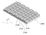
도 7a 내지 도 7b의 실시예에서, 입력 DOE(200)는 입력 광을 제1 방향(X 방향으로 라벨링됨)으로 지향시키도록 구성된 블레이즈 격자를 포함한다. 블레이즈 격자는 제1 방향에 수직으로(즉, Y 방향으로) 연장되는 반복 행들(211)을 포함한다.In the embodiments of FIGS. 7A-7B, the input DOE (200) includes a blazed grating configured to direct input light in a first direction (labeled the X-direction). The blazed grating includes repeating rows (211) extending perpendicular to the first direction (i.e., in the Y-direction).
그러나, 각각의 행(211)은 또한 제2 방향(Y 방향으로 라벨링됨)에 수직으로 연장되는 레귤러 노치들(210)을 포함한다. 레귤러 노치들(210)은 입력 광을 제2 방향으로(그리고 선택적으로 또한 제2 방향과 반대인 제3 방향으로) 지향시키도록 구성된다.However, each row (211) also includes regular notches (210) extending perpendicularly to the second direction (labeled the Y direction). The regular notches (210) are configured to direct input light in the second direction (and optionally also in a third direction opposite the second direction).
이 예에서, 레귤러 노치들(210)은 벌크 도파관의 표면이 수정되지 않은 평탄한 부분들이다. 그러나, 레귤러 노치들(210)은 대신에 벌크 도파관 위로 상승되거나 벌크 도파관 내로 매립될 수 있다. 추가적으로, 레귤러 노치들(210) 자체는 (예를 들어, 도 7c의 대안적인 입력 DOE(200B)에 도시된 바와 같이) 행들(211)과 유사하게, 제1 방향으로 입력 광을 지향시키도록 구성된 블레이즈 섹션들을 포함할 수 있다. 그러나, 레귤러 노치들(210)의 평균 높이는 행들(211)의 평균 높이보다 높거나 낮다.In this example, the regular notches (210) are flat portions of the bulk waveguide surface that are not modified. However, the regular notches (210) may instead be elevated above or embedded within the bulk waveguide. Additionally, the regular notches (210) themselves may include blazed sections configured to direct input light in a first direction, similar to the rows (211) (e.g., as illustrated in the alternative input DOE (200B) of FIG. 7C ). However, the average height of the regular notches (210) is higher or lower than the average height of the rows (211).
도 7a는 입력 DOE(200)의 평면도이며, 블레이즈 격자 행들(211)의 변화하는 높이는 회색 톤을 사용하여 표시된다. 도 7b는 입력 DOE(200)의 사시도이다.Fig. 7a is a plan view of the input DOE (200), with the varying heights of the blaze grid rows (211) indicated using gray tones. Fig. 7b is a perspective view of the input DOE (200).
도 8a 내지 도 8d는 도파관에 대한 다른 입력 DOE의 예시들이다. 예를 들어, 도 8a 내지 도 8d의 입력 DOE는 도 4 또는 도 5의 실시예에 적합하다.Figures 8a to 8d are examples of other input DOEs for the waveguide. For example, the input DOEs of Figures 8a to 8d are suitable for the embodiments of Figures 4 or 5.
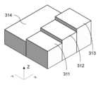
도 8a 내지 도 8d의 실시예에서, 입력 DOE(300)(도 8c 및 도 8d)는 반복 단위들(310)(도 8a)을 포함하는 반복 구조이다. 각각의 반복 단위(310)는 도파관의 평면에 수직인 각자의 높이를 각각 갖는 직사각형 요소들의 그리드로 구성된다(평면은 예시된 X 및 Y 방향들에 의해 정의된다). 도 8a 및 도 8c는 각자의 높이들이 회색 톤을 사용하여 표시되는 입력 DOE(300)의 평면도들이다. 도 8b 및 도 8d는 각각 반복 단위(310) 및 전체 입력 DOE(300)에서의 높이 치수를 도시하는 사시도이다.In the embodiments of FIGS. 8A through 8D, the input DOE (300) (FIGS. 8C and 8D) is a repeating structure comprising repeating units (310) (FIG. 8A). Each repeating unit (310) is comprised of a grid of rectangular elements, each having its own height perpendicular to the plane of the waveguide (the plane being defined by the illustrated X and Y directions). FIGS. 8A and 8C are plan views of the input DOE (300) in which the respective heights are indicated using gray tones. FIGS. 8B and 8D are perspective views illustrating height dimensions in the repeating unit (310) and the entire input DOE (300), respectively.
도 8a 및 도 8b를 참조하면, 이 예에서, 직사각형 요소들의 그리드는 직사각형 요소들의 계단형 시리즈를 갖는 제1 영역(311, 312, 313)을 포함하고, 직사각형 요소들의 계단형 시리즈의 높이들은 일 단부에서의 요소(313)로부터 타 단부에서의 요소(311)로 감소한다. 이 계단형 시리즈는 매끄러운 기울기에 가깝다. 그러한 의사-기울기(pseudo-slope)가 (도 8c에 도시된 바와 같이) 양의 X 방향으로 다수의 반복 단위들(310)에 걸쳐 반복될 때, 종합적인 효과는 양의 X 방향으로 광을 결합하도록 구성된 블레이즈 격자에 근접하는 반복적인 기울기이다. 이것은 의사-블레이즈 격자라고도 지칭될 수 있다.Referring to FIGS. 8a and 8b , in this example, the grid of rectangular elements includes a first region (311, 312, 313) having a stepped series of rectangular elements, the heights of the stepped series of rectangular elements decreasing from element (313) at one end to element (311) at the other end. This stepped series approximates a smooth slope. When such a pseudo-slope is repeated over a plurality of repeating units (310) in the positive X direction (as illustrated in FIG. 8c ), the overall effect is a repeated slope approaching a blazed grating configured to couple light in the positive X direction. This may also be referred to as a pseudo-blazed grating.
추가적으로, 반복 단위(310)에서, 직사각형 요소들의 그리드는 제1 영역의 직사각형 요소들의 계단에 수직인 방향인 Y 방향으로 제1 영역(311, 312, 313)으로부터 오프셋된 제2 영역(314)을 포함한다. 제2 영역(314)은 제1 영역(311, 312, 313)의 평균 높이와 상이한 평균 높이를 갖는다. 단위(310)가 Y 방향으로 반복되어 입력 DOE(300)(도 8c 및 도 8d)를 생성할 때, 제1 영역과 제2 영역 사이의 교번하는 평균 높이는 양 및 음의 Y 방향 모두에서 동일하게 광을 결합하도록 구성된 선형 격자를 제공한다.Additionally, in the repeating unit (310), the grid of rectangular elements includes a second region (314) offset from the first region (311, 312, 313) in the Y direction, a direction perpendicular to the steps of the rectangular elements of the first region. The second region (314) has an average height that is different than the average height of the first regions (311, 312, 313). When the unit (310) is repeated in the Y direction to generate the input DOE (300) (FIGS. 8C and 8D), the alternating average heights between the first and second regions provide a linear grid configured to couple light equally in both the positive and negative Y directions.
이 예에서, 제2 영역들(314)은 벌크 도파관의 표면이 수정되지 않은 평탄한 부분들이다. 그러나, 제2 영역들(314)은 대신에 벌크 도파관 위로 상승되거나 벌크 도파관 내로 매립될 수 있다. 추가적으로, 제2 영역들(314) 자체는 (예를 들어, 도 8e의 대안적인 입력 DOE(300B)에 예시된 바와 같이) 제1 영역들(311, 312, 313)과 유사하게, 제1 방향으로 입력 광을 지향시키도록 구성된 블레이즈 또는 의사-블레이즈 섹션들을 포함할 수 있다. 그러나, 제2 영역들(314)의 평균 높이는 제1 영역들(311, 312, 313)의 평균 높이보다 높거나 낮다.In this example, the second regions (314) are flat portions of the bulk waveguide surface that are not modified. However, the second regions (314) may instead be elevated above or embedded within the bulk waveguide. Additionally, the second regions (314) themselves may include blazed or pseudo-blazed sections configured to direct input light in a first direction, similar to the first regions (311, 312, 313) (e.g., as illustrated in the alternative input DOE (300B) of FIG. 8e). However, the average height of the second regions (314) is higher or lower than the average height of the first regions (311, 312, 313).
도 8a 내지 8d의 예를 참조하면, X 방향에 평행한 격자 벡터를 갖는 블레이즈 격자 또는 의사-블레이즈 격자와 Y 방향에 평행한 격자 벡터를 갖는 선형 격자의 조합은, 양의 X 방향에서의 수신된 광의 제1 부분, 양의 Y 방향에서의 광의 제2 부분, 및 음의 Y 방향에서의 수신된 광의 제3 부분을 결합할 수 있는 입력 DOE를 제공한다. 따라서, 이 구조는 도 4 또는 도 5의 입력 DOE(101)의 기능들을 충족시킬 수 있는 단일 격자 구조의 예이다.Referring to examples of FIGS. 8a to 8d, a combination of a blazed grating or pseudo-blazed grating having a grating vector parallel to the X direction and a linear grating having a grating vector parallel to the Y direction provides an input DOE capable of combining a first portion of received light in the positive X direction, a second portion of light in the positive Y direction, and a third portion of received light in the negative Y direction. Thus, this structure is an example of a single grating structure capable of satisfying the functions of the input DOE (101) of FIG. 4 or 5.
또한, X 방향에 평행한 격자 벡터를 갖는 격자가 블레이징되거나 의사-블레이징되기 때문에, 음의 X 방향으로 회절된 광의 부분이 감소하고, 따라서 입력 DOE는 도 5의 3개의 방향으로 광을 더 효율적으로 결합할 수 있다.Additionally, since the grating with the grating vector parallel to the X direction is blazed or pseudo-blazed, the portion of light diffracted in the negative X direction is reduced, and thus the input DOE can more efficiently couple light into the three directions in Fig. 5.
의사-블레이징은 Y 방향으로 반복 단위의 추가의 계단들을 제공함으로써 X 및 Y 방향 둘 다로 연장될 수 있다. 이 구성에 의해, 음의 Y 방향으로 회절된 광의 부분이 또한 감소할 수 있고, 입력 DOE는 도 4의 2개의 방향으로 광을 더 효율적으로 결합할 수 있다. 유사하게, 블레이징은 방향들 각각에서 1차원 블레이징의 선형 조합으로서 2개의 방향으로 적용될 수 있다. 또한, 블레이징 및 의사-블레이징은 선형 조합을 사용하여 2개의 방향으로 조합될 수 있다.The pseudo-blazing can be extended in both the X and Y directions by providing additional steps of repeating units in the Y direction. With this configuration, the fraction of light diffracted in the negative Y direction can also be reduced, and the input DOE can more efficiently couple light in the two directions in Fig. 4. Similarly, the blazing can be applied in two directions as a linear combination of one-dimensional blazing in each of the directions. Furthermore, the blazing and pseudo-blazing can be combined in two directions using a linear combination.
Claims (12)
Translated fromKorean도파관;
프로젝터로부터 광을 수신하고, 수신된 광을 복수의 광학 경로를 따라 상기 도파관 내로 결합하도록 구성된 입력 회절 광학 요소(DOE);
제1 방향을 따라 상기 입력 DOE로부터 오프셋되고, 상기 수신된 광을 상기 도파관 밖으로 그리고 뷰어를 향해 결합하도록 구성된 출력 DOE; 및
상기 제1 방향과 상이한 제2 방향을 따라 상기 입력 DOE로부터 오프셋된 제1 터닝 DOE(turning DOE)
를 포함하고, 상기 입력 DOE는 상기 수신된 광의 제1 부분을 상기 제1 방향으로 상기 출력 DOE를 향해 결합하도록 구성되고,
상기 입력 DOE는 상기 수신된 광의 제2 부분을 상기 제2 방향으로 상기 제1 터닝 DOE를 향해 결합하도록 구성되고, 상기 제1 터닝 DOE는 상기 수신된 광의 상기 제2 부분을 상기 출력 DOE를 향해 회절시키도록 구성되는, 광학 디바이스.As an optical device for use in an augmented reality or virtual reality display,
wave-guide;
An input diffractive optical element (DOE) configured to receive light from a projector and couple the received light into the waveguide along a plurality of optical paths;
an output DOE offset from the input DOE along the first direction and configured to couple the received light out of the waveguide and toward the viewer; and
A first turning DOE offset from the input DOE along a second direction different from the first direction.
, wherein the input DOE is configured to couple a first portion of the received light toward the output DOE in the first direction,
An optical device, wherein the input DOE is configured to couple a second portion of the received light toward the first turning DOE in the second direction, and the first turning DOE is configured to diffract the second portion of the received light toward the output DOE.
상기 출력 DOE는 상기 제2 방향으로 상기 입력 DOE보다 넓고, 상기 제1 터닝 DOE는 상기 수신된 광의 상기 제2 부분을 상기 제1 방향으로 상기 출력 DOE를 향해 회절시키도록 구성되는, 광학 디바이스.In the first paragraph,
An optical device wherein said output DOE is wider than said input DOE in said second direction, and wherein said first turning DOE is configured to diffract said second portion of said received light toward said output DOE in said first direction.
상기 입력 DOE는 상기 수신된 광의 상기 제1 부분을 상기 제1 방향으로 회절시키도록 구성된 제1 격자 및 상기 수신된 광의 상기 제2 부분을 상기 제2 방향으로 회절시키도록 구성된 제2 격자를 포함하는, 광학 디바이스.In paragraph 1 or 2,
An optical device, wherein the input DOE comprises a first grating configured to diffract the first portion of the received light in the first direction and a second grating configured to diffract the second portion of the received light in the second direction.
상기 제1 격자 또는 상기 제2 격자는 블레이즈 격자를 포함하는, 광학 디바이스.In the third paragraph,
An optical device, wherein the first grating or the second grating comprises a blazed grating.
상기 입력 DOE의 반복 단위는 상기 도파관의 평면에 수직인 각자의 높이를 각각 갖는 직사각형 요소들의 그리드를 포함하고, 상기 직사각형 요소들 중 적어도 3개는 상이한 높이들을 갖는, 광학 디바이스.In clause 3 or 4,
An optical device wherein the repeating unit of the input DOE comprises a grid of rectangular elements each having a height perpendicular to the plane of the waveguide, at least three of the rectangular elements having different heights.
상기 직사각형 요소들의 그리드는 직사각형 요소들의 계단형 시리즈(stepped series)를 갖는 제1 영역을 포함하고, 상기 직사각형 요소들의 계단형 시리즈의 높이들은 상기 제1 방향 및 상기 제2 방향 중 하나의 방향으로 증분적으로 변화하는, 광학 디바이스.In paragraph 5,
An optical device wherein the grid of rectangular elements comprises a first region having a stepped series of rectangular elements, the heights of the stepped series of rectangular elements incrementally changing in one of the first direction and the second direction.
상기 제1 영역은 상기 하나의 방향으로 상기 반복 단위의 길이에 걸쳐 연장되고, 상기 직사각형 요소들의 계단형 시리즈의 높이들은 규칙적인 간격들로 상기 하나의 방향으로 변경되어, 상기 입력 DOE는 상기 하나의 방향으로 광을 결합하기 위한 블레이즈 격자(blazed grating)에 근접하는, 광학 디바이스.In Article 6,
An optical device wherein said first region extends over the length of said repeating unit in said one direction, and wherein the heights of said stepped series of rectangular elements are varied at regular intervals in said one direction, such that said input DOE approximates a blazed grating for coupling light in said one direction.
상기 직사각형 요소들의 그리드는 상기 제1 및 상기 제2 방향 중 다른 방향으로 상기 제1 영역으로부터 오프셋된 제2 영역을 포함하고, 상기 제2 영역 내의 직사각형 요소들의 평균 높이는 상기 제1 영역 내의 직사각형 요소들의 평균 높이와 상이한, 광학 디바이스.In clause 6 or 7,
An optical device wherein the grid of said rectangular elements includes a second region offset from the first region in a different direction from the first and second directions, and wherein an average height of the rectangular elements within the second region is different from an average height of the rectangular elements within the first region.
상기 입력 DOE는 상기 수신된 광의 제3 부분을 상기 제1 및 상기 제2 방향들과 상이한 제3 방향으로 결합하도록 추가로 구성되고, 상기 광학 디바이스는 상기 제3 방향을 따라 상기 입력 DOE로부터 오프셋된 제2 터닝 DOE를 포함하고, 상기 제2 터닝 DOE는 상기 수신된 광의 상기 제3 부분을 상기 출력 DOE를 향해 회절시키도록 구성되는, 광학 디바이스.In any one of claims 1 to 8,
An optical device wherein the input DOE is further configured to couple a third portion of the received light in a third direction that is different from the first and second directions, and wherein the optical device includes a second turning DOE offset from the input DOE along the third direction, the second turning DOE being configured to diffract the third portion of the received light toward the output DOE.
상기 제3 방향은 상기 제2 방향과 반대인, 광학 디바이스.In Article 9,
An optical device wherein the third direction is opposite to the second direction.
상기 제1 격자 및 상기 제2 격자는 상기 도파관의 동일한 표면 상에 배열되는, 광학 디바이스.In any one of claims 1 to 10,
An optical device wherein the first grating and the second grating are arranged on the same surface of the waveguide.
상기 제1 격자 및 상기 제2 격자는 상기 도파관의 반대 표면들 상에 배열되는, 광학 디바이스.In any one of claims 1 to 10,
An optical device wherein the first grating and the second grating are arranged on opposite surfaces of the waveguide.
Applications Claiming Priority (3)
| Application Number | Priority Date | Filing Date | Title |
|---|---|---|---|
| EP22195747.5 | 2022-09-14 | ||
| EP22195747 | 2022-09-14 | ||
| PCT/EP2023/075362WO2024056832A1 (en) | 2022-09-14 | 2023-09-14 | Multipath optical device |
Publications (1)
| Publication Number | Publication Date |
|---|---|
| KR20250065682Atrue KR20250065682A (en) | 2025-05-13 |
Family
ID=83355376
Family Applications (1)
| Application Number | Title | Priority Date | Filing Date |
|---|---|---|---|
| KR1020257011528APendingKR20250065682A (en) | 2022-09-14 | 2023-09-14 | Multipath optical devices |
Country Status (4)
| Country | Link |
|---|---|
| EP (1) | EP4587879A1 (en) |
| KR (1) | KR20250065682A (en) |
| CN (1) | CN119866467A (en) |
| WO (1) | WO2024056832A1 (en) |
Families Citing this family (1)
| Publication number | Priority date | Publication date | Assignee | Title |
|---|---|---|---|---|
| GB2638464A (en)* | 2024-02-23 | 2025-08-27 | Nokia Technologies Oy | Optical apparatus, modules and devices |
Family Cites Families (5)
| Publication number | Priority date | Publication date | Assignee | Title |
|---|---|---|---|---|
| GB2529003B (en) | 2014-08-03 | 2020-08-26 | Wave Optics Ltd | Optical device |
| US10481317B2 (en) | 2016-08-22 | 2019-11-19 | Magic Leap, Inc. | Nanograting method and apparatus |
| EP4250242A3 (en) | 2017-01-23 | 2023-11-29 | Magic Leap, Inc. | Eyepiece for virtual, augmented, or mixed reality systems |
| GB201705160D0 (en) | 2017-03-30 | 2017-05-17 | Wave Optics Ltd | Waveguide for an augmented reality or virtual reality display |
| US11022790B2 (en)* | 2019-06-14 | 2021-06-01 | Magic Leap, Inc. | Optical eyepiece using single-sided patterning of grating couplers |
- 2023
- 2023-09-14KRKR1020257011528Apatent/KR20250065682A/enactivePending
- 2023-09-14WOPCT/EP2023/075362patent/WO2024056832A1/ennot_activeCeased
- 2023-09-14EPEP23771872.1Apatent/EP4587879A1/enactivePending
- 2023-09-14CNCN202380065478.XApatent/CN119866467A/enactivePending
Also Published As
| Publication number | Publication date |
|---|---|
| EP4587879A1 (en) | 2025-07-23 |
| WO2024056832A1 (en) | 2024-03-21 |
| CN119866467A (en) | 2025-04-22 |
Similar Documents
| Publication | Publication Date | Title |
|---|---|---|
| US10359635B2 (en) | Exit pupil expanding diffractive optical waveguiding device | |
| US20230032474A1 (en) | Waveguide for an augmented reality or virtual reality display | |
| US11953685B2 (en) | Angular uniformity waveguide for augmented or virtual reality | |
| CN211528820U (en) | Optical structure and augmented reality or virtual reality device | |
| KR20250065682A (en) | Multipath optical devices | |
| GB2566788A (en) | Device for augmented reality or virtual reality display | |
| US20230161162A1 (en) | Waveguide for an augmented reality or virtual reality display | |
| HK40048223B (en) | Device for augmented reality or virtual reality display | |
| HK40048223A (en) | Device for augmented reality or virtual reality display |
Legal Events
| Date | Code | Title | Description |
|---|---|---|---|
| PA0105 | International application | Patent event date:20250409 Patent event code:PA01051R01D Comment text:International Patent Application | |
| PA0201 | Request for examination | ||
| PG1501 | Laying open of application |