KR20250056016A - Robot cleaner station and robot cleaner system having the same - Google Patents
Robot cleaner station and robot cleaner system having the sameDownload PDFInfo
- Publication number
- KR20250056016A KR20250056016AKR1020230139866AKR20230139866AKR20250056016AKR 20250056016 AKR20250056016 AKR 20250056016AKR 1020230139866 AKR1020230139866 AKR 1020230139866AKR 20230139866 AKR20230139866 AKR 20230139866AKR 20250056016 AKR20250056016 AKR 20250056016A
- Authority
- KR
- South Korea
- Prior art keywords
- pad
- robot cleaner
- mop
- mop pad
- holder
- Prior art date
- Legal status (The legal status is an assumption and is not a legal conclusion. Google has not performed a legal analysis and makes no representation as to the accuracy of the status listed.)
- Pending
Links
Images


Classifications
- A—HUMAN NECESSITIES
- A47—FURNITURE; DOMESTIC ARTICLES OR APPLIANCES; COFFEE MILLS; SPICE MILLS; SUCTION CLEANERS IN GENERAL
- A47L—DOMESTIC WASHING OR CLEANING; SUCTION CLEANERS IN GENERAL
- A47L11/00—Machines for cleaning floors, carpets, furniture, walls, or wall coverings
- A47L11/40—Parts or details of machines not provided for in groups A47L11/02 - A47L11/38, or not restricted to one of these groups, e.g. handles, arrangements of switches, skirts, buffers, levers
- A47L11/4091—Storing or parking devices, arrangements therefor; Means allowing transport of the machine when it is not being used
- A—HUMAN NECESSITIES
- A47—FURNITURE; DOMESTIC ARTICLES OR APPLIANCES; COFFEE MILLS; SPICE MILLS; SUCTION CLEANERS IN GENERAL
- A47L—DOMESTIC WASHING OR CLEANING; SUCTION CLEANERS IN GENERAL
- A47L11/00—Machines for cleaning floors, carpets, furniture, walls, or wall coverings
- A47L11/40—Parts or details of machines not provided for in groups A47L11/02 - A47L11/38, or not restricted to one of these groups, e.g. handles, arrangements of switches, skirts, buffers, levers
- A47L11/4011—Regulation of the cleaning machine by electric means; Control systems and remote control systems therefor
- A—HUMAN NECESSITIES
- A47—FURNITURE; DOMESTIC ARTICLES OR APPLIANCES; COFFEE MILLS; SPICE MILLS; SUCTION CLEANERS IN GENERAL
- A47L—DOMESTIC WASHING OR CLEANING; SUCTION CLEANERS IN GENERAL
- A47L11/00—Machines for cleaning floors, carpets, furniture, walls, or wall coverings
- A47L11/40—Parts or details of machines not provided for in groups A47L11/02 - A47L11/38, or not restricted to one of these groups, e.g. handles, arrangements of switches, skirts, buffers, levers
- A47L11/4036—Parts or details of the surface treating tools
- A47L11/4038—Disk shaped surface treating tools
- A—HUMAN NECESSITIES
- A47—FURNITURE; DOMESTIC ARTICLES OR APPLIANCES; COFFEE MILLS; SPICE MILLS; SUCTION CLEANERS IN GENERAL
- A47L—DOMESTIC WASHING OR CLEANING; SUCTION CLEANERS IN GENERAL
- A47L2201/00—Robotic cleaning machines, i.e. with automatic control of the travelling movement or the cleaning operation
- A47L2201/02—Docking stations; Docking operations
- A47L2201/028—Refurbishing floor engaging tools, e.g. cleaning of beating brushes
Landscapes
- Manipulator (AREA)
- Cleaning Implements For Floors, Carpets, Furniture, Walls, And The Like (AREA)
Abstract
Translated fromKoreanDescription
Translated fromKorean본 개시는 로봇 청소기 스테이션에 관한 것으로서, 더욱 상세하게는 걸레 패드를 자동으로 교환하고 걸레 패드를 세척할 수 있는 로봇 청소기 스테이션 및 이를 구비한 로봇 청소기 시스템에 관한 것이다.The present disclosure relates to a robot cleaner station, and more specifically, to a robot cleaner station capable of automatically exchanging mop pads and washing mop pads, and a robot cleaner system having the same.
기술의 발전에 따라 다양한 종류의 로봇 청소기가 시판되고 있다.As technology advances, various types of robot vacuum cleaners are available on the market.
일반적인 로봇 청소기는 피청소면을 자율 주행하면서 피청소면에 있는 먼지나 오물을 흡입하여 수거할 수 있도록 형성되어 있다.A typical robot vacuum cleaner is designed to autonomously move around the surface to be cleaned and suck up and collect dust and dirt on the surface to be cleaned.
일부 로봇 청소기는 피청소면을 걸레질하는 걸레질 기능을 구비하고, 피청소면의 오물을 수거하는 기능을 구비하고 있지 않다.Some robot vacuum cleaners have a mopping function that cleans the surface to be cleaned, but do not have a function to collect dirt from the surface to be cleaned.
일부 로봇 청소기는 피청소면의 오물을 수거하는 기능과 피청소면을 걸레질하는 기능을 모두 구비하고 있다.Some robot vacuum cleaners have both the function of collecting dirt from the surface to be cleaned and the function of mopping the surface to be cleaned.
걸레질 기능을 구비한 로봇 청소기의 일부는 사용자가 사용한 걸레 패드를 수동으로 새로운 걸레 패드로 교체하도록 형성된다.Some robot vacuum cleaners with mopping functions are configured to require the user to manually replace the used mop pad with a new one.
걸레질 기능을 구비한 로봇 청소기의 일부는 걸레 패드를 세척할 수 있는 세척장치를 구비한 로봇 청소기 스테이션을 포함할 수 있다. 로봇 청소기 스테이션은 사용된 걸레 패드가 부착된 로봇 청소기가 세척장치에 진입하면, 사용된 걸레 패드가 로봇 청소기에 부착되어 있는 상태로 사용된 걸레 패드를 세척한다. 걸레 패드의 세척이 완료되면, 로봇 청소기는 로봇 청소기 스테이션에서 벗어나서 피청소면의 걸레질을 수행한다.Some of the robot cleaners with a mopping function may include a robot cleaner station having a cleaning device capable of cleaning a mop pad. When a robot cleaner with a used mop pad attached enters the cleaning device, the robot cleaner station washes the used mop pad while the used mop pad remains attached to the robot cleaner. When the mop pad is cleaned, the robot cleaner leaves the robot cleaner station and performs mopping of the surface to be cleaned.
본 개시의 하나 이상의 실시 예에 의한 로봇 청소기 스테이션(1)은, 베이스(10); 상기 베이스의 상면에 설치되며, 걸레 패드를 안치하고 세척할 수 있도록 형성된 패드 세척장치(20); 상기 패드 세척장치(20)에 놓인 사용된 걸레 패드를 이동시키고, 세척된 걸레 패드를 상기 패드 세척장치(20)에 놓도록 형성된 패드 이동장치(30); 및 로봇 청소기(100)가 상기 세척된 걸레 패드를 장착하고 상기 베이스에서 멀어지면, 상기 패드 이동장치(30)를 제어하여 상기 사용된 걸레 패드를 상기 패드 세척장치(20)로 이동시키고 상기 패드 세척장치(20)를 이용하여 상기 사용된 걸레 패드를 세척하도록 형성된 프로세서(90);를 포함할 수 있다.A robot cleaner station (1) according to one or more embodiments of the present disclosure may include: a base (10); a pad washing device (20) installed on an upper surface of the base and formed to place and wash a mop pad; a pad moving device (30) formed to move a used mop pad placed on the pad washing device (20) and place a washed mop pad on the pad washing device (20); and a processor (90) formed to control the pad moving device (30) to move the used mop pad to the pad washing device (20) and wash the used mop pad using the pad washing device (20) when the robot cleaner (100) is equipped with the washed mop pad and moves away from the base.
본 개시의 하나 이상의 실시 예에 따르면, 상기 패드 이동장치(30)는, 직사각형 형상으로 형성된 승강 프레임(40); 상기 승강 프레임(40)의 내측에 회전 가능하게 설치되며, 상기 걸레 패드가 고정되는 회전판(50); 상기 승강 프레임(40)을 상하로 이동시키도록 형성된 승강장치(60); 및 상기 회전판(50)을 회전시키도록 형성된 회전장치(70);를 포함할 수 있다.According to one or more embodiments of the present disclosure, the pad moving device (30) may include: a lifting frame (40) formed in a rectangular shape; a rotating plate (50) rotatably installed on the inside of the lifting frame (40) and to which the mop pad is fixed; a lifting device (60) formed to move the lifting frame (40) up and down; and a rotating device (70) formed to rotate the rotating plate (50).
본 개시의 하나 이상의 실시 예에 따르면, 상기 회전판(50)은, 제1면; 상기 제1면의 반대면인 제2면; 상기 제1면에 설치되며, 상기 걸레 패드를 선택적으로 잡을 수 있도록 형성된 제1홀더 록커(52); 및 상기 제2면에 설치되며, 상기 걸레 패드를 선택적으로 잡을 수 있도록 형성된 제2홀더 록커(52);를 포함할 수 있다.According to one or more embodiments of the present disclosure, the turntable (50) may include: a first surface; a second surface opposite to the first surface; a first holder locker (52) installed on the first surface and formed to selectively hold the mop pad; and a second holder locker (52) installed on the second surface and formed to selectively hold the mop pad.
본 개시의 하나 이상의 실시 예에 따르면, 상기 회전장치(60)는, 상기 회전판(50)의 양측면에서 돌출되도록 설치되는 한 쌍의 회전 돌기(71); 상기 승강 프레임(40)의 양측에 설치되며, 상기 승강 프레임(40)이 상승할 때 상기 한 쌍의 회전 돌기(71) 중 하나와 간섭되어 상기 회전판(50)이 상기 승강 프레임(40)에 대해 일정 각도 회전하도록 하는 한 쌍의 간섭 레버(75); 및 상기 승강 프레임(40)의 양측면에 형성되며, 상기 한 쌍의 회전 돌기(71)가 수용되도록 형성되는 두 쌍의 멈춤 홈(72);을 포함할 수 있다.According to one or more embodiments of the present disclosure, the rotating device (60) may include: a pair of rotating projections (71) installed so as to protrude from both sides of the rotating plate (50); a pair of interference levers (75) installed on both sides of the elevating frame (40) and configured to interfere with one of the pair of rotating projections (71) when the elevating frame (40) rises, thereby allowing the rotating plate (50) to rotate at a predetermined angle with respect to the elevating frame (40); and two pairs of stop grooves (72) formed on both sides of the elevating frame (40) and formed so as to receive the pair of rotating projections (71).
본 개시의 하나 이상의 실시 예에 따르면, 상기 승강장치(60)는, 상기 승강 프레임(40)의 양측면에 설치되는 한 쌍의 랙 기어; 상기 한 쌍의 랙 기어에 치합되는 한 쌍의 피니언; 상기 한 쌍의 피니언을 구동하는 구동 기어; 상기 구동 기어를 회전시키는 모터; 및 상기 승강 프레임(40)의 상하 이동을 안내하는 한 쌍의 안내부재;를 포함할 수 있다.According to one or more embodiments of the present disclosure, the lifting device (60) may include: a pair of rack gears installed on both sides of the lifting frame (40); a pair of pinions meshed with the pair of rack gears; a driving gear driving the pair of pinions; a motor rotating the driving gears; and a pair of guide members guiding the up and down movement of the lifting frame (40).
본 개시의 하나 이상의 실시 예에 따르면, 상기 구동 기어는 상기 한 쌍의 피니언에 치합되는 제1구동 기어와 제2구동 기어, 및 상기 제1구동 기어와 상기 제2구동 기어를 연결하는 연결 샤프트를 포함할 수 있다.According to one or more embodiments of the present disclosure, the drive gear may include a first drive gear and a second drive gear meshed with the pair of pinions, and a connecting shaft connecting the first drive gear and the second drive gear.
본 개시의 하나 이상의 실시 예에 따르면, 상기 패드 이동장치(30)는, 직사각형 형상으로 형성되며, 상기 걸레 패드가 고정되는 승강판(31); 및 상기 승강판(31)을 상하로 이동시키도록 형성된 승강장치(60);를 포함할 수 있다.According to one or more embodiments of the present disclosure, the pad moving device (30) may include a lifting plate (31) formed in a rectangular shape and on which the mop pad is fixed; and a lifting device (60) formed to move the lifting plate (31) up and down.
본 개시의 하나 이상의 실시 예에 따르면, 상기 승강장치(60)는, 상기 승강판(31)의 양측면에 설치되는 한 쌍의 랙 기어; 상기 한 쌍의 랙 기어에 치합되는 한 쌍의 피니언; 상기 한 쌍의 피니언을 구동하는 구동 기어; 상기 구동 기어를 회전시키는 모터; 및 상기 승강판(31)의 상하 이동을 안내하는 한 쌍의 안내부재;를 포함할 수 있다.According to one or more embodiments of the present disclosure, the elevator device (60) may include: a pair of rack gears installed on both sides of the elevator plate (31); a pair of pinions meshed with the pair of rack gears; a driving gear driving the pair of pinions; a motor rotating the driving gears; and a pair of guide members guiding the up and down movement of the elevator plate (31).
본 개시의 하나 이상의 실시 예에 따르면, 상기 승강판(31)은, 상기 승강판(31)의 하면에 설치되며, 상기 걸레 패드를 선택적으로 잡을 수 있도록 형성된 홀더 록커(52)를 포함할 수 있다.According to one or more embodiments of the present disclosure, the lifting plate (31) may include a holder rocker (52) installed on a lower surface of the lifting plate (31) and formed to selectively hold the mop pad.
본 개시의 하나 이상의 실시 예에 따르면, 상기 홀더 록커(52)는, 중앙에 형성된 록킹 구멍(521); 및 상기 록킹 구멍(521)의 내주면에 일정 간격으로 설치된 복수의 볼 스프링(53);을 포함할 수 있다.According to one or more embodiments of the present disclosure, the holder locker (52) may include a locking hole (521) formed in the center; and a plurality of ball springs (53) installed at regular intervals on the inner surface of the locking hole (521).
본 개시의 하나 이상의 실시 예에 따르면, 상기 패드 이동장치(30)는, 상기 걸레 패드를 고정시키도록 형성되는 패드 홀더(81); 및 상기 패드 홀더(81)를 선택적으로 잡을 수 있도록 형성된 홀더 록커(52);를 포함할 수 있다. 상기 패드 홀더(81)는, 하면에 상기 걸레 패드가 부착되는 홀더판(82); 및 상기 홀더판(82)의 상면의 중앙에서 돌출되도록 형성되는 고정 돌기(83);를 포함할 수 있다.According to one or more embodiments of the present disclosure, the pad moving device (30) may include a pad holder (81) formed to fix the mop pad; and a holder locker (52) formed to selectively hold the pad holder (81). The pad holder (81) may include a holder plate (82) to which the mop pad is attached on a lower surface; and a fixing protrusion (83) formed to protrude from the center of the upper surface of the holder plate (82).
본 개시의 하나 이상의 실시 예에 따르면, 상기 홀더 록커(52)는, 상기 패드 홀더(81)의 고정 돌기(83)가 삽입되도록 중심에 형성된 록킹 구멍(521); 및 상기 록킹 구멍(521)의 둘레에 설치되며, 상기 고정 돌기(83)를 선택적으로 고정하도록 형성된 록킹 부재;를 포함할 수 있다.According to one or more embodiments of the present disclosure, the holder locker (52) may include a locking hole (521) formed in the center so that the fixing projection (83) of the pad holder (81) is inserted; and a locking member installed around the locking hole (521) and formed to selectively fix the fixing projection (83).
본 개시의 하나 이상의 실시 예에 의한 로봇 청소기 스테이션(200)은, 세척된 걸레 패드를 이용하여 피청소면에 대해 걸레질을 수행하도록 형성된 로봇 청소기(100); 및 상기 로봇 청소기(100)에 상기 세척된 걸레 패드를 공급하고, 상기 로봇 청소기(100)의 걸레질이 완료되면 사용된 걸레 패드를 세척된 걸레 패드로 교체하고, 상기 로봇 청소기(100)가 걸레질을 하는 동안 상기 사용된 걸레 패드를 세척하도록 형성된 로봇 청소기 스테이션(1);을 포함할 수 있다. 상기 로봇 청소기 스테이션(1)은, 베이스(10); 상기 베이스(10)의 상면에 설치되며, 상기 세척된 걸레 패드를 안치하고 상기 사용된 걸레 패드를 세척할 수 있도록 형성된 패드 세척장치(20); 상기 패드 세척장치(20)에 놓인 상기 사용된 걸레 패드를 이동시키고, 상기 세척된 걸레 패드를 상기 패드 세척장치(20)에 놓도록 형성된 패드 이동장치(30); 및 상기 로봇 청소기(100)가 상기 세척된 걸레 패드를 장착하고 상기 베이스를 떠나 상기 피청소면을 걸레질하는 동안, 상기 패드 이동장치(30)를 제어하여 상기 사용된 걸레 패드를 상기 패드 세척장치(20)로 이동시키고, 상기 패드 세척장치(20)를 제어하여 상기 사용된 걸레 패드를 세척하도록 형성된 프로세서(90);를 포함할 수 있다.A robot cleaner station (200) according to one or more embodiments of the present disclosure may include a robot cleaner (100) configured to perform mopping on a surface to be cleaned using a washed mop pad; and a robot cleaner station (1); configured to supply the washed mop pad to the robot cleaner (100), replace a used mop pad with a washed mop pad when the mopping of the robot cleaner (100) is completed, and wash the used mop pad while the robot cleaner (100) is mopping. The robot cleaner station (1) includes: a base (10); a pad washing device (20) installed on an upper surface of the base (10) and configured to place the washed mop pad and wash the used mop pad; a pad moving device (30) configured to move the used mop pad placed on the pad washing device (20) and place the washed mop pad on the pad washing device (20); And, while the robot cleaner (100) is equipped with the washed mop pad and leaves the base to mop the surface to be cleaned, it may include a processor (90) configured to control the pad moving device (30) to move the used mop pad to the pad washing device (20) and to control the pad washing device (20) to wash the used mop pad.
본 개시의 실시 예들의 상술하거나 다른 측면, 특징, 이익들은 첨부도면을 참조한 아래의 설명으로부터 더욱 명백해질 것이다. 첨부도면에서:
도 1은 본 개시의 하나 이상의 실시 예에 의한 로봇 청소기 스테이션(1)을 나타내는 사시도이다.
도 2는 케이스(2)를 제거한 본 개시의 하나 이상의 실시 예에 의한 로봇 청소기 스테이션(1)을 나타내는 사시도이다.
도 3은 도 1의 로봇 청소기 스테이션(1)을 선A-A를 따라 절단하여 나타낸 단면도이다.
도 4는 본 개시의 하나 이상의 실시 예에 의한 로봇 청소기 스테이션(1)의 패드 이동장치(30)의 승강 프레임(40)과 회전판을 나타내는 분해 사시도이다.
도 5는 본 개시의 하나 이상의 실시 예에 의한 패드 이동장치(30)의 회전판의 단면도이다.
도 6은 본 개시의 하나 이상의 실시 예에 의한 패드 이동장치(30)의 간섭 레버(75)를 나타내는 사시도이다.
도 7은 본 개시의 하나 이상의 실시 예에 의한 로봇 청소기 스테이션(1)에 사용되는 걸레 패드 조립체(80A)를 나타내는 사시도이다.
도 8은 도 7의 걸레 패드 조립체(80A)의 단면도이다.
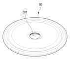
도 9는 도 7의 걸레 패드 조립체(80A)의 걸레 패드(80)를 나타내는 사시도이다.
도 10은 도 7의 걸레 패드 조립체(80A)의 패드 홀더(81)의 저면 사시도이다.
도 11은 걸레 패드(80)가 결합된 본 개시의 하나 이상의 실시 예에 의한 로봇 청소기 스테이션(1)의 회전판을 나타내는 단면도이다.
도 12는 본 개시의 하나 이상의 실시 예에 의한 로봇 청소기 스테이션(1)의 홀더 록커(52)에 패드 홀더(81)가 결합된 상태를 나타내는 단면도이다.
도 13은 도 12의 홀더 록커(52)에서 패드 홀더(81)가 분리된 상태를 나타내는 단면도이다.
도 14는 본 개시의 하나 이상의 실시 예에 의한 로봇 청소기 시스템을 나타내는 사시도이다.
도 15는 본 개시의 하나 이상의 실시 예에 의한 로봇 청소기 시스템의 블록(85)도이다.
도 16a 내지 도 16h는 본 개시의 하나 이상의 실시 예에 의한 로봇 청소기 시스템에 의한 걸레 패드(80)의 교체 방법을 설명하기 위한 도면이다.
도 17은 본 개시의 하나 이상의 실시 예에 의한 로봇 청소기 스테이션(1)을 나타내는 사시도이다.
도 18은 도 17의 로봇 청소기 스테이션(1)의 승강판(31)을 나타내는 저면 사시도이다.
도 19는 본 개시의 하나 이상의 실시 예에 의한 로봇 청소기 스테이션(1)에 사용되는 2개의 걸레 패드 조립체(80A)가 적층된 상태를 나타내는 단면 사시도이다.
도 20은 본 개시의 하나 이상의 실시 예에 의한 로봇 청소기 스테이션(1)의 승강판(31)의 홀더 록커(52)에 걸레 패드 조립체(80A)의 패드 홀더(81)가 결합된 상태를 나타내는 단면도이다.
도 21a 내지 도 21f는 본 개시의 하나 이상의 실시 예에 의한 로봇 청소기 시스템에 의한 걸레 패드(80)의 교체 방법을 설명하기 위한 도면이다.The above and other aspects, features, and advantages of the embodiments of the present disclosure will become more apparent from the following description taken in conjunction with the accompanying drawings, in which:
FIG. 1 is a perspective view showing a robot cleaner station (1) according to one or more embodiments of the present disclosure.
FIG. 2 is a perspective view showing a robot cleaner station (1) according to one or more embodiments of the present disclosure with the case (2) removed.
Fig. 3 is a cross-sectional view showing the robot cleaner station (1) of Fig. 1 cut along line AA.
FIG. 4 is an exploded perspective view showing a lifting frame (40) and a turntable of a pad moving device (30) of a robot cleaner station (1) according to one or more embodiments of the present disclosure.
FIG. 5 is a cross-sectional view of a rotary plate of a pad moving device (30) according to one or more embodiments of the present disclosure.
FIG. 6 is a perspective view showing an interference lever (75) of a pad moving device (30) according to one or more embodiments of the present disclosure.
FIG. 7 is a perspective view showing a mop pad assembly (80A) used in a robot cleaner station (1) according to one or more embodiments of the present disclosure.
Fig. 8 is a cross-sectional view of the mop pad assembly (80A) of Fig. 7.
FIG. 9 is a perspective view showing the mop pad (80) of the mop pad assembly (80A) of FIG. 7.
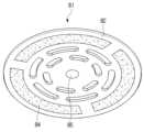
Fig. 10 is a bottom perspective view of the pad holder (81) of the mop pad assembly (80A) of Fig. 7.
FIG. 11 is a cross-sectional view showing a turntable of a robot cleaner station (1) according to one or more embodiments of the present disclosure to which a mop pad (80) is coupled.
FIG. 12 is a cross-sectional view showing a state in which a pad holder (81) is coupled to a holder rocker (52) of a robot cleaner station (1) according to one or more embodiments of the present disclosure.
Fig. 13 is a cross-sectional view showing a state in which the pad holder (81) is separated from the holder locker (52) of Fig. 12.
FIG. 14 is a perspective view illustrating a robot vacuum cleaner system according to one or more embodiments of the present disclosure.
FIG. 15 is a block diagram (85) of a robot vacuum cleaner system according to one or more embodiments of the present disclosure.
FIGS. 16A to 16H are drawings for explaining a method of replacing a mop pad (80) by a robot cleaner system according to one or more embodiments of the present disclosure.
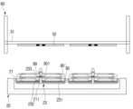
FIG. 17 is a perspective view showing a robot cleaner station (1) according to one or more embodiments of the present disclosure.
Fig. 18 is a bottom perspective view showing the lifting plate (31) of the robot cleaner station (1) of Fig. 17.
FIG. 19 is a cross-sectional perspective view showing a state in which two mop pad assemblies (80A) used in a robot cleaner station (1) according to one or more embodiments of the present disclosure are stacked.
FIG. 20 is a cross-sectional view showing a state in which a pad holder (81) of a mop pad assembly (80A) is coupled to a holder rocker (52) of a lifting plate (31) of a robot cleaner station (1) according to one or more embodiments of the present disclosure.
FIGS. 21A to 21F are drawings for explaining a method of replacing a mop pad (80) by a robot cleaner system according to one or more embodiments of the present disclosure.
본 문서의 다양한 실시예들 및 이에 사용된 용어들은 본 문서에 기재된 기술적 특징들을 특정한 실시예들로 한정하려는 것이 아니며, 해당 실시 예의 다양한 변경(modifications), 균등물(equivalents), 또는 대체물(alternatives)을 포함하는 것으로 이해되어야 한다.It should be understood that the various embodiments of this document and the terminology used herein are not intended to limit the technical features described in this document to specific embodiments, but rather to include various modifications, equivalents, or alternatives of the embodiments.
도면의 설명과 관련하여, 유사한 또는 관련된 구성요소에 대해서는 유사한 참조 부호가 사용될 수 있다.In connection with the description of the drawings, similar reference numerals may be used for similar or related components.
아이템에 대응하는 명사의 단수 형은 관련된 문맥상 명백하게 다르게 지시하지 않는 한, 상기 아이템 한 개 또는 복수 개를 포함할 수 있다.The singular form of a noun corresponding to an item may include one or more of said items, unless the context clearly indicates otherwise.
본 문서에서, "A 또는 B", "A 및 B 중 적어도 하나", "A 또는 B 중 적어도 하나", "A, B 또는 C", "A, B 및 C 중 적어도 하나", 및 "A, B, 또는 C 중 적어도 하나"와 같은 문구들 각각은 그 문구들 중 해당하는 문구에 함께 나열된 항목들 중 어느 하나, 또는 그들의 모든 가능한 조합을 포함할 수 있다.In this document, each of the phrases "A or B", "at least one of A and B", "at least one of A or B", "A, B, or C", "at least one of A, B, and C", and "at least one of A, B, or C" can include any one of the items listed together in that phrase, or all possible combinations of them.
"및/또는"이라는 용어는 복수의 관련된 기재된 구성요소들의 조합 또는 복수의 관련된 기재된 구성요소들 중의 어느 구성요소를 포함한다.The term "and/or" includes any combination of multiple related described elements or any one of multiple related described elements.
"제1", "제2", 또는 "첫째" 또는 "둘째"와 같은 용어들은 단순히 해당 구성요소를 다른 해당 구성요소와 구분하기 위해 사용될 수 있으며, 해당 구성요소들을 다른 측면(예: 중요성 또는 순서)에서 한정하지 않는다.Terms such as "first", "second", or "first" or "second" may be used merely to distinguish one component from another, and do not limit the components in any other respect (e.g., importance or order).
어떤(예: 제1) 구성요소가 다른(예: 제2) 구성요소에, "기능적으로" 또는 "통신적으로"라는 용어와 함께 또는 이런 용어 없이, "커플드" 또는 "커넥티드"라고 언급된 경우, 그것은 상기 어떤 구성요소가 상기 다른 구성요소에 직접적으로(예: 유선으로), 무선으로, 또는 제3 구성요소를 통하여 연결될 수 있다는 것을 의미한다.When a component (e.g., a first component) is referred to as being “coupled” or “connected” to another component (e.g., a second component), with or without the terms “functionally” or “communicatively,” it means that the component can be connected to the other component directly (e.g., wired), wirelessly, or through a third component.
"포함하다" 또는 "가지다"등의 용어는 본 문서에 기재된 특징, 숫자, 단계, 동작, 구성요소, 부품 또는 이들을 조합한 것이 존재함을 지정하려는 것이지, 하나 또는 그 이상의 다른 특징들이나 숫자, 단계, 동작, 구성요소, 부품 또는 이들을 조합한 것들의 존재 또는 부가 가능성을 미리 배제하지 않는다.The terms "include" or "have" and the like are intended to specify the presence of a feature, number, step, operation, component, part, or combination thereof described in this document, but do not exclude the presence or addition of one or more other features, numbers, steps, operations, components, parts, or combinations thereof.
어떤 구성요소가 다른 구성요소와 "연결", "결합", "지지" 또는 "접촉"되어 있다고 할 때, 이는 구성요소들이 직접적으로 연결, 결합, 지지 또는 접촉되는 경우뿐 아니라, 제3 구성요소를 통하여 간접적으로 연결, 결합, 지지 또는 접촉되는 경우를 포함한다.When a component is said to be “connected,” “coupled,” “supported,” or “contacted” with another component, this includes not only cases where the components are directly connected, coupled, supported, or in contact, but also cases where the components are indirectly connected, coupled, supported, or in contact through a third component.
어떤 구성요소가 다른 구성요소 "상에" 위치하고 있다고 할 때, 이는 어떤 구성요소가 다른 구성요소에 접해 있는 경우뿐 아니라 두 구성요소 사이에 또 다른 구성요소가 존재하는 경우도 포함한다.When we say that a component is "on" another component, this includes not only cases where the component is in contact with the other component, but also cases where there is another component between the two components.
또한, 본 개시에서 사용한 '선단', '후단', '상부', '하부', '상단', '하단' 등의 용어는 도면을 기준으로 정의한 것이며, 이 용어에 의해 각 구성요소의 형상 및 위치가 제한되는 것은 아니다.In addition, the terms 'leading end', 'rear end', 'upper end', 'lower end', 'top end', 'bottom end', etc. used in the present disclosure are defined based on the drawings, and the shape and position of each component are not limited by these terms.
본 개시는 로봇 청소기에 장착된 사용된 걸레 패드를 세척된 걸레 패드로 교체하고, 로봇 청소기가 세척된 걸레 패드를 이용하여 걸레질을 수행하는 동안 사용된 걸레 패드를 세척할 수 있는 로봇 청소기 스테이션에 관련된다.The present disclosure relates to a robot cleaner station capable of replacing a used mop pad mounted on a robot cleaner with a cleaned mop pad and washing the used mop pad while the robot cleaner performs mopping using the cleaned mop pad.
이하, 본 개시의 하나 이상의 실시 예에 의한 로봇 청소기 스테이션(1)에 대해 첨부된 도 1을 참조하여 상세하게 설명한다.Hereinafter, a robot cleaner station (1) according to one or more embodiments of the present disclosure will be described in detail with reference to the attached FIG. 1.
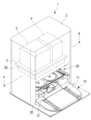
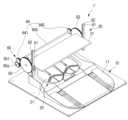
도 1은 본 개시의 하나 이상의 실시 예에 의한 로봇 청소기 스테이션(1)을 나타내는 사시도이다.FIG. 1 is a perspective view showing a robot cleaner station (1) according to one or more embodiments of the present disclosure.
도 1을 참조하면, 본 개시의 하나 이상의 실시 예에 의한 로봇 청소기 스테이션(1)은 베이스(10), 패드 세척장치(20), 패드 이동장치(30)를 포함할 수 있다.Referring to FIG. 1, a robot cleaner station (1) according to one or more embodiments of the present disclosure may include a base (10), a pad washing device (20), and a pad moving device (30).
베이스(10)는 로봇 청소기 스테이션(1)을 지지할 수 있도록 형성된다. 따라서, 로봇 청소기 스테이션(1)은 베이스(10)에 의해 설치면에 설치될 수 있다. 여기서, 설치면은 로봇 청소기(100)가 이동할 수 있는 피청소면일 수 있다.The base (10) is formed so as to support the robot cleaner station (1). Accordingly, the robot cleaner station (1) can be installed on an installation surface by the base (10). Here, the installation surface can be a surface to be cleaned on which the robot cleaner (100) can move.
베이스(10)는 로봇 청소기(100)가 베이스(10)의 상면으로 올라오는 진입로(11)를 포함할 수 있다. 진입로(11)는 경사면으로 형성될 수 있다.The base (10) may include an access road (11) through which the robot cleaner (100) ascends to the upper surface of the base (10). The access road (11) may be formed as a slope.
패드 세척장치(20)는 베이스(10)의 상면에 설치될 수 있다. 패드 세척장치(20)는 걸레 패드(80)를 세척할 수 있도록 형성된다. 패드 세척장치(20)는 패드 이동장치(30)에 의해 지지되는 걸레 패드(80)의 하면을 세척할 수 있도록 형성된다.The pad cleaning device (20) can be installed on the upper surface of the base (10). The pad cleaning device (20) is formed to be able to clean the mop pad (80). The pad cleaning device (20) is formed to be able to clean the lower surface of the mop pad (80) supported by the pad moving device (30).
패드 세척장치(20)는 걸레 패드(80)를 안치할 수 있도록 형성된다. 패드 세척장치(20)는 걸레 패드(80)를 안치할 수 있는 패드 안치부(21)를 포함할 수 있다. 패드 안치부(21)는 베이스(10)의 상면에 대해 수직 방향으로 일정 거리 이동할 수 있도록 형성된다. 본 실시 예의 경우에는 패드 세척장치(20)는 2개의 걸레 패드(80)를 안치할 수 있도록 2개의 패드 안치부(21)를 포함한다.The pad washing device (20) is formed so that a mop pad (80) can be placed thereon. The pad washing device (20) may include a pad placing portion (21) on which a mop pad (80) can be placed. The pad placing portion (21) is formed so that it can move a certain distance in a vertical direction with respect to the upper surface of the base (10). In the case of the present embodiment, the pad washing device (20) includes two pad placing portions (21) so that two mop pads (80) can be placed thereon.
로봇 청소기(100)가 진입로를 따라 로봇 청소기 스테이션(1)의 내부로 진입하면, 로봇 청소기(100)의 하면에 마련된 걸레질 장치는 베이스(10)에 설치된 패드 세척장치(20)를 마주할 수 있다. 로봇 청소기(100)는 패드 세척장치(20)의 패드 안치부(21)에 사용한 걸레 패드(80)를 위치시킬 수 있다.When the robot cleaner (100) enters the interior of the robot cleaner station (1) along the entrance, the mopping device provided on the lower surface of the robot cleaner (100) can face the pad washing device (20) installed on the base (10). The robot cleaner (100) can position the mop pad (80) used in the pad placement section (21) of the pad washing device (20).
패드 이동장치(30)는 패드 세척장치(20)에 놓인 사용된 걸레 패드(80')를 이동시킬 수 있도록 형성된다. 구체적으로, 패드 이동장치(30)는 패드 세척장치(20)에 놓인 걸레 패드(80)를 픽업하여 상측으로 로봇 청소기(100)의 높이 이상으로 이동시킬 수 있도록 형성된다.The pad moving device (30) is formed so as to be able to move a used mop pad (80') placed on the pad washing device (20). Specifically, the pad moving device (30) is formed so as to be able to pick up a mop pad (80) placed on the pad washing device (20) and move it upward to a height higher than that of the robot cleaner (100).
패드 이동장치(30)는 세척된 걸레 패드(80)를 패드 세척장치(20)에 놓도록 형성될 수 있다. 구체적으로, 패드 이동장치(30)는 사용된 걸레 패드(80')를 지지하여 패드 세척장치(20)가 세척할 수 있도록 하고, 세척이 완료된 걸레 패드(80)를 패드 세척장치(20)의 상측으로 일정 거리 이격된 위치로 이동시킬 수 있도록 형성된다. 패드 이동장치(30)는 세척된 걸레 패드(80)를 패드 세척장치(20)의 패드 안치부(21)에 위치시킬 수 있다.The pad moving device (30) may be formed to place a washed mop pad (80) on the pad washing device (20). Specifically, the pad moving device (30) is formed to support a used mop pad (80') so that the pad washing device (20) can wash it, and to move the washed mop pad (80) to a position spaced a certain distance above the pad washing device (20). The pad moving device (30) may place the washed mop pad (80) on the pad placement portion (21) of the pad washing device (20).
본 실시 예의 경우에, 패드 이동장치(30)는 2개의 걸레 패드(80)를 한 번에 이동시킬 수 있도록 형성된다. 그러나, 이는 일 예일 뿐이며, 패드 이동장치(30)는 로봇 청소기(100)에 부착되는 걸레 패드(80)의 개수에 대응하는 걸레 패드(80)를 한 번에 이동시킬 수 있도록 형성될 수 있다. 예를 들면, 패드 이동장치(30)는 한 개의 걸레 패드(80) 또는 세 개 이상의 걸레 패드(80)를 한 번에 이동시킬 수 있도록 형성될 수 있다.In the case of the present embodiment, the pad moving device (30) is formed so as to be able to move two mop pads (80) at a time. However, this is only an example, and the pad moving device (30) may be formed so as to be able to move mop pads (80) corresponding to the number of mop pads (80) attached to the robot cleaner (100) at a time. For example, the pad moving device (30) may be formed so as to be able to move one mop pad (80) or three or more mop pads (80) at a time.
패드 이동장치(30)와 패드 세척장치(20)는 프로세서(90)에 의해 제어될 수 있다. 프로세서(90)는 패드 이동장치(30)를 제어하여 패드 이동장치(30)가 걸레 패드(80)를 이동시키도록 형성될 수 있다. 프로세서(90)는 패드 세척장치(20)를 제어하여 패드 세척장치(20)가 패드 이동장치(30)에 의해 이동된 걸레 패드(80)를 세척하도록 형성될 수 있다.The pad moving device (30) and the pad washing device (20) may be controlled by the processor (90). The processor (90) may be configured to control the pad moving device (30) so that the pad moving device (30) moves the mop pad (80). The processor (90) may be configured to control the pad washing device (20) so that the pad washing device (20) washes the mop pad (80) moved by the pad moving device (30).
예를 들면, 로봇 청소기(100)가 패드 세척장치(20)에 놓인 세척된 걸레 패드(80)를 장착하고 베이스(10)에서 멀어지면, 프로세서(90)는 패드 이동장치(30)를 제어하여 사용된 걸레 패드(80')를 패드 세척장치(20)로 이동시키고, 패드 세척장치(20)를 제어하여 사용된 걸레 패드(80')를 세척하도록 형성될 수 있다. 프로세서(90)는 패드 건조장치(29)를 이용하여 세척된 걸레 패드(80)를 건조시키도록 형성될 수 있다. 즉, 프로세서(90)는 패드 이동장치(30)가 걸레 패드(80)를 패드 세척장치(20)에 위치시키고 지지하는 상태에서 패드 세척장치(20)가 걸레 패드(80)를 세척하도록 제어할 수 있다.For example, when the robot cleaner (100) is equipped with a washed mop pad (80) placed on the pad washing device (20) and moves away from the base (10), the processor (90) may be configured to control the pad moving device (30) to move the used mop pad (80') to the pad washing device (20) and to control the pad washing device (20) to wash the used mop pad (80'). The processor (90) may be configured to dry the washed mop pad (80) using the pad drying device (29). That is, the processor (90) may control the pad washing device (20) to wash the mop pad (80) while the pad moving device (30) positions and supports the mop pad (80) on the pad washing device (20).
로봇 청소기 스테이션(1)은 케이스(2)를 포함할 수 있다. 케이스(2)는 베이스(10), 패드 세척장치(20), 및 패드 이동장치(30)를 수용하며 지지할 수 있도록 형성된다.The robot cleaner station (1) may include a case (2). The case (2) is formed to accommodate and support a base (10), a pad cleaning device (20), and a pad moving device (30).
케이스(2)의 전면에는 로봇 청소기(100)가 들어오는 입구가 마련될 수 있다. 로봇 청소기(100)는 케이스(2)의 입구를 통해 베이스(10)의 상면으로 올라올 수 있다.An entrance for a robot cleaner (100) to enter may be provided on the front of the case (2). The robot cleaner (100) may rise to the upper surface of the base (10) through the entrance of the case (2).
로봇 청소기 스테이션(1)은 패드 건조장치(29)를 포함할 수 있다. 패드 건조장치(29)는 패드 세척장치(20)에 의해 세척된 걸레 패드(80)를 건조시킬 수 있도록 형성될 수 있다. 예를 들면, 패드 건조장치(29)는 적어도 한 개의 팬을 포함할 수 있다.The robot cleaner station (1) may include a pad drying device (29). The pad drying device (29) may be configured to dry a mop pad (80) washed by the pad washing device (20). For example, the pad drying device (29) may include at least one fan.
패드 건조장치(29)는 패드 이동장치(30)의 상측으로 케이스(2)에 설치될 수 있다. 걸레 패드(80)가 패드 이동장치(30)에 의해 상측으로 이동하여 패드 건조장치(29)의 아래에 위치하면, 패드 건조장치(29)는 패드 이동장치(30)에 고정된 걸레 패드(80)를 건조시킬 수 있다.The pad drying device (29) can be installed in the case (2) above the pad moving device (30). When the mop pad (80) is moved upward by the pad moving device (30) and positioned below the pad drying device (29), the pad drying device (29) can dry the mop pad (80) fixed to the pad moving device (30).
로봇 청소기 스테이션(1)은 청수통(3)과 먼지통(4)을 포함할 수 있다. 청수통(3)과 먼지통(4)은 패드 건조장치(29)의 상측에 설치될 수 있다. 패드 건조장치(29)의 상측에는 청수통(3)과 먼지통(4)을 지지하는 중간판(5)이 설치될 수 있다. 패드 건조장치(29)는 중간판(5)의 아래에 설치될 수 있다.The robot cleaner station (1) may include a water tank (3) and a dust tank (4). The water tank (3) and the dust tank (4) may be installed on the upper side of the pad drying device (29). An intermediate plate (5) supporting the water tank (3) and the dust tank (4) may be installed on the upper side of the pad drying device (29). The pad drying device (29) may be installed below the intermediate plate (5).
청수통(3)은 베이스(10)의 상면에 위치한 로봇 청소기(100)에 물을 공급할 수 있도록 형성된다. 먼지통(4)은 베이스(10)의 상면에 위치한 로봇 청소기(100)에 수거된 먼지와 오물을 수거할 수 있도록 형성된다.The water tank (3) is formed to be able to supply water to the robot cleaner (100) located on the upper surface of the base (10). The dust tank (4) is formed to be able to collect dust and dirt collected by the robot cleaner (100) located on the upper surface of the base (10).
이하, 본 개시의 하나 이상의 실시 예에 의한 로봇 청소기 스테이션(1)의 패드 이동장치(30)에 대해 첨부된 도 2 내지 도 6을 참조하여 상세하게 설명한다.Hereinafter, a pad moving device (30) of a robot cleaner station (1) according to one or more embodiments of the present disclosure will be described in detail with reference to the attached FIGS. 2 to 6.
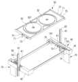
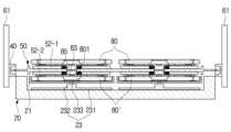
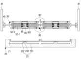
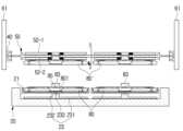
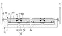
도 2는 케이스(2)를 제거한 본 개시의 하나 이상의 실시 예에 의한 로봇 청소기 스테이션(1)을 나타내는 사시도이다. 도 3은 도 1의 로봇 청소기 스테이션(1)을 선A-A를 따라 절단하여 나타낸 단면도이다. 도 4는 본 개시의 하나 이상의 실시 예에 의한 로봇 청소기 스테이션(1)의 패드 이동장치(30)의 승강 프레임(40)과 회전판을 나타내는 사시도이다. 도 5는 본 개시의 하나 이상의 실시 예에 의한 패드 이동장치(30)의 회전판의 단면도이다. 도 6은 본 개시의 하나 이상의 실시 예에 의한 패드 이동장치(30)의 간섭 레버(75)의 사시도이다.FIG. 2 is a perspective view showing a robot cleaner station (1) according to one or more embodiments of the present disclosure with the case (2) removed. FIG. 3 is a cross-sectional view showing the robot cleaner station (1) of FIG. 1 cut along line A-A. FIG. 4 is a perspective view showing a lifting frame (40) and a turntable of a pad moving device (30) of a robot cleaner station (1) according to one or more embodiments of the present disclosure. FIG. 5 is a cross-sectional view of a turntable of a pad moving device (30) according to one or more embodiments of the present disclosure. FIG. 6 is a perspective view of an interference lever (75) of a pad moving device (30) according to one or more embodiments of the present disclosure.
도 2 내지 도 6을 참조하면, 본 개시의 하나 이상의 실시 예에 의한 패드 이동장치(30)는 승강 프레임(40), 회전판(50), 승강장치(60), 및 회전장치(70)를 포함할 수 있다.Referring to FIGS. 2 to 6, a pad moving device (30) according to one or more embodiments of the present disclosure may include a lifting frame (40), a rotating plate (50), an lifting device (60), and a rotating device (70).
승강 프레임(40)은 직사각형 형상으로 형성될 수 있다. 승강 프레임(40)은 내부가 빈 직사각형 형상의 창틀 형상으로 형성될 수 있다. 승강 프레임(40)은 회전판(50)의 회전을 지지할 수 있도록 형성된다. 승강 프레임(40)은 승강장치(60)에 의해 상하로 이동할 수 있도록 형성된다.The lifting frame (40) may be formed in a rectangular shape. The lifting frame (40) may be formed in a rectangular window frame shape with an empty interior. The lifting frame (40) is formed so as to be able to support the rotation of the turntable (50). The lifting frame (40) is formed so as to be able to move up and down by the lifting device (60).
회전판(50)은 대략 직사각형 평판 형상으로 형성될 수 있다. 회전판(50)은 승강 프레임(40)의 내측에 회전 가능하게 설치될 수 있다. 회전판(50)은 걸레 패드(80)를 지지하며, 고정할 수 있도록 형성된다. 본 실시 예의 경우, 회전판(50)은 2개의 걸레 패드(80)를 지지 및 고정하도록 형성된다.The turntable (50) can be formed in a roughly rectangular flat plate shape. The turntable (50) can be rotatably installed on the inside of the lifting frame (40). The turntable (50) supports the mop pad (80) and is formed so as to be fixed. In the present embodiment, the turntable (50) is formed so as to support and fix two mop pads (80).
회전판(50)은 한 쌍의 회전축(51)을 포함할 수 있다. 한 쌍의 회전축(51)은 회전판(50)의 좌측면과 우측면의 중심에 설치될 수 있다. 한 쌍의 회전축(51)을 지지하면, 회전판(50)은 수평 상태를 유지할 수 있다.The turntable (50) may include a pair of rotation shafts (51). The pair of rotation shafts (51) may be installed at the center of the left and right sides of the turntable (50). By supporting the pair of rotation shafts (51), the turntable (50) can be maintained in a horizontal state.
승강 프레임(40)은 회전판(50)의 한 쌍의 회전축(51)에 대응하는 한 쌍의 축구멍(41)을 포함할 수 있다. 한 쌍의 축구멍(41)은 승강 프레임(40)의 양측면, 즉 승강 프레임(40)의 좌측면과 우측면에 형성될 수 있다. 회전판(50)의 한 쌍의 회전축(51)은 승강 프레임(40)의 한 쌍의 축구멍(41)에 삽입될 수 있다. 따라서, 회전판(50)은 승강 프레임(40)에 대해 회전할 수 있다.The lifting frame (40) may include a pair of soccer holes (41) corresponding to a pair of rotation axes (51) of the turntable (50). The pair of soccer holes (41) may be formed on both sides of the lifting frame (40), that is, on the left side and the right side of the lifting frame (40). The pair of rotation axes (51) of the turntable (50) may be inserted into the pair of soccer holes (41) of the lifting frame (40). Therefore, the turntable (50) may rotate with respect to the lifting frame (40).
회전판(50)에 외력이 가해지지 않는 경우, 회전판(50)은 승강 프레임(40)과 평행을 유지하도록 설치될 수 있다.When no external force is applied to the turntable (50), the turntable (50) can be installed so as to remain parallel to the lifting frame (40).
회전판(50)은 홀더 록커(52)를 포함할 수 있다. 홀더 록커(52)는 회전판(50)의 제1면과 제2면에 설치될 수 있다. 여기서, 회전판(50)의 제2면은 제1면의 반대쪽 면을 말한다. 이하, 회전판(50)의 제1면에 설치되는 홀더 록커(52)를 제1홀더 록커라 하고, 회전판(50)의 제2면에 설치되는 홀더 록커(52)를 제2홀더 록커라 한다. 본 실시 예에 의한 회전판(50)은 한 번에 2개의 걸레 패드(80)를 픽업할 수 있도록 제1면에는 2개의 제1홀더 록커(52)가 설치되고, 제2면에는 2개의 제2홀더 록커(52)가 설치된다. 제1홀더 록커(52)와 제2홀더 록커(52)는 동일한 구조로 형성되므로, 이하에서는 한 개의 홀더 록커(52)에 대해 설명한다.The turntable (50) may include a holder locker (52). The holder locker (52) may be installed on the first surface and the second surface of the turntable (50). Here, the second surface of the turntable (50) refers to the surface opposite the first surface. Hereinafter, the holder locker (52) installed on the first surface of the turntable (50) is referred to as a first holder locker, and the holder locker (52) installed on the second surface of the turntable (50) is referred to as a second holder locker. The turntable (50) according to the present embodiment has two first holder lockers (52) installed on the first surface and two second holder lockers (52) installed on the second surface so that two mop pads (80) can be picked up at a time. Since the first holder locker (52) and the second holder locker (52) are formed with the same structure, one holder locker (52) will be described below.
홀더 록커(52)는 걸레 패드(80)를 지지 및 고정할 수 있도록 형성된다. 홀더 록커(52)는 걸레 패드(80)를 선택적으로 잡거나 놓을 수 있도록 형성될 수 있다. 본 실시 예와 같이 걸레 패드(80)가 패드 홀더(81)에 고정된 경우에는, 홀더 록커(52)는 패드 홀더(81)를 선택적으로 잡거나 놓을 수 있도록 형성될 수 있다.The holder locker (52) is formed to support and fix the mop pad (80). The holder locker (52) may be formed to selectively hold or place the mop pad (80). In the case where the mop pad (80) is fixed to the pad holder (81) as in the present embodiment, the holder locker (52) may be formed to selectively hold or place the pad holder (81).
홀더 록커(52)는 원판 형상으로 형성될 수 있다. 홀더 록커(52)의 중심에는 록킹 구멍(521)이 형성될 수 있다. 록킹 구멍(521)은 패드 홀더(81)의 고정 돌기(83)가 삽입될 수 있도록 형성된다.The holder locker (52) may be formed in a disc shape. A locking hole (521) may be formed in the center of the holder locker (52). The locking hole (521) is formed so that the fixing projection (83) of the pad holder (81) can be inserted.
홀더 록커(52)는 패드 홀더(81)의 고정 돌기(83)를 선택적으로 고정하도록 형성되는 록킹 부재를 포함할 수 있다. 록킹 부재는 홀더 록커(52)의 록킹 구멍(521)에 설치될 수 있다. 록킹 부재는 패드 홀더(81)의 고정 돌기(83)를 고정할 수 있는 한 다양한 구조로 형성될 수 있다.The holder locker (52) may include a locking member formed to selectively secure the fixing projection (83) of the pad holder (81). The locking member may be installed in the locking hole (521) of the holder locker (52). The locking member may be formed in various structures as long as it can secure the fixing projection (83) of the pad holder (81).
예를 들면, 록킹 부재는 복수의 볼 스프링(53)으로 형성될 수 있다. 복수의 볼 스프링(53) 각각은 한 개의 볼(531)과 볼(531)을 지지하는 한 개의 코일 스프링(532)으로 형성될 수 있다. 복수의 볼 스프링(53)은 홀더 록커(52)의 록킹 구멍(521)의 내주면에 일정 간격으로 설치될 수 있다.For example, the locking member may be formed of a plurality of ball springs (53). Each of the plurality of ball springs (53) may be formed of one ball (531) and one coil spring (532) supporting the ball (531). The plurality of ball springs (53) may be installed at regular intervals on the inner surface of the locking hole (521) of the holder locker (52).
록킹 구멍(521)의 내주면에는 복수의 볼 스프링(53)이 설치되는 복수의 볼 스프링 구멍이 형성될 수 있다. 따라서, 홀더 록커(52)의 복수의 볼 스프링 구멍에 복수의 볼 스프링(53)을 설치하면, 복수의 볼(531)만 록킹 구멍(521)의 내주면으로 돌출될 수 있다. 복수의 볼 스프링(53) 각각의 볼(531)은 록킹 구멍(521)의 반지름 방향으로 이동할 수 있다. 따라서, 복수의 볼 스프링(53)은 록킹 구멍(521)에 삽입된 패드 홀더(81)의 고정 돌기(83)를 고정할 수 있다.A plurality of ball spring holes in which a plurality of ball springs (53) are installed may be formed on the inner surface of the locking hole (521). Accordingly, when a plurality of ball springs (53) are installed in the plurality of ball spring holes of the holder locker (52), only the plurality of balls (531) may protrude into the inner surface of the locking hole (521). Each ball (531) of the plurality of ball springs (53) may move in the radial direction of the locking hole (521). Accordingly, the plurality of ball springs (53) may fix the fixing projection (83) of the pad holder (81) inserted into the locking hole (521).
걸레 패드(80)와 패드 홀더(81)는 걸레 패드 조립체(80A)를 형성할 수 있다. 이하, 도 7 내지 도 10을 참조하여, 본 개시의 하나 이상의 실시 예에 의한 로봇 청소기 스테이션(1)에 사용되는 걸레 패드 조립체(80A)에 대해 상세하게 설명한다.A mop pad (80) and a pad holder (81) can form a mop pad assembly (80A). Hereinafter, with reference to FIGS. 7 to 10, a mop pad assembly (80A) used in a robot cleaner station (1) according to one or more embodiments of the present disclosure will be described in detail.
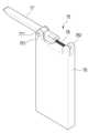
도 7은 본 개시의 하나 이상의 실시 예에 의한 로봇 청소기 스테이션(1)에 사용되는 걸레 패드 조립체(80A)를 나타내는 사시도이다. 도 8은 도 7의 걸레 패드 조립체(80A)의 단면도이다. 도 9는 도 7의 걸레 패드 조립체(80A)의 걸레 패드(80)를 나타내는 사시도이다. 도 10은 도 7의 걸레 패드 조립체(80A)의 패드 홀더(81)의 저면 사시도이다.FIG. 7 is a perspective view showing a mop pad assembly (80A) used in a robot cleaner station (1) according to one or more embodiments of the present disclosure. FIG. 8 is a cross-sectional view of the mop pad assembly (80A) of FIG. 7. FIG. 9 is a perspective view showing a mop pad (80) of the mop pad assembly (80A) of FIG. 7. FIG. 10 is a bottom perspective view of a pad holder (81) of the mop pad assembly (80A) of FIG. 7.
도 7 및 도 8을 참조하면, 본 개시의 하나 이상의 실시 예에 의한 걸레 패드 조립체(80A)는 패드 홀더(81)와 걸레 패드(80)를 포함한다.Referring to FIGS. 7 and 8, a mop pad assembly (80A) according to one or more embodiments of the present disclosure includes a pad holder (81) and a mop pad (80).
걸레 패드(80)는 패드 홀더(81)의 하면에 고정될 수 있다. 걸레 패드(80)는 패드 홀더(81)의 하면에 분리 가능하게 고정될 수 있다. 예를 들면, 걸레 패드(80)는 패드 홀더(81)의 하면에 벨크로(Velcro)로 부착될 수 있다.The mop pad (80) can be fixed to the lower surface of the pad holder (81). The mop pad (80) can be detachably fixed to the lower surface of the pad holder (81). For example, the mop pad (80) can be attached to the lower surface of the pad holder (81) with Velcro.
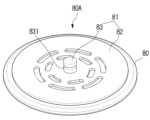
도 9를 참조하면, 걸레 패드(80)는 대략 원판 형상으로 형성될 수 있다. 걸레 패드(80)의 중심에는 걸레 구멍(801)이 형성될 수 있다. 걸레 구멍(801)은 걸레 패드(80)를 상하로 관통하도록 형성될 수 있다.Referring to Fig. 9, the mop pad (80) may be formed in an approximately circular shape. A mop hole (801) may be formed at the center of the mop pad (80). The mop hole (801) may be formed to penetrate the mop pad (80) upwardly and downwardly.
걸레 패드(80)의 일면은 피청소면을 걸레질할 수 있는 걸레면으로 형성되고, 반대면은 패드 홀더(81)의 하면에 착탈될 수 있는 착탈면으로 형성된다. 착탈면은 벨크로에 부착될 수 있도록 형성될 수 있다. 걸레 패드(80)는 착탈면을 이용하여 로봇 청소기(100)의 걸레질 장치에 착탈될 수 있다.One side of the mop pad (80) is formed as a mop surface that can mop the surface to be cleaned, and the opposite side is formed as a detachable surface that can be attached to the lower surface of the pad holder (81). The detachable surface can be formed so that it can be attached to Velcro. The mop pad (80) can be attached to the mop device of the robot cleaner (100) using the detachable surface.
여기서, 걸레면이 더러워진 걸레 패드(80)를 사용된 걸레 패드(80')라 하고, 패드 세척장치(20)에 의해 걸레면이 세척된 걸레 패드(80)를 세척된 걸레 패드(80)라 한다. 즉, 사용된 걸레 패드(80')가 패드 세척장치(20)에 의해 세척되면, 세척된 걸레 패드(80)가 된다.Here, a mop pad (80) with a dirty mop surface is referred to as a used mop pad (80'), and a mop pad (80) with a mop surface washed by a pad washing device (20) is referred to as a washed mop pad (80). That is, when a used mop pad (80') is washed by a pad washing device (20), it becomes a washed mop pad (80).
도 7과 도 8을 참조하면, 패드 홀더(81)는 홀더판(82)과 고정 돌기(83)를 포함할 수 있다.Referring to FIGS. 7 and 8, the pad holder (81) may include a holder plate (82) and a fixing protrusion (83).
홀더판(82)은 하면에 걸레 패드(80)를 부착할 수 있도록 형성된다. 홀더판(82)은 걸레 패드(80)에 대응하는 형상으로 형성될 수 있다. 예를 들면, 홀더판(82)은 원판 형상으로 형성될 수 있다. 홀더판(82)은 걸레 패드(80)보다 작거나 유사한 지름을 갖도록 형성될 수 있다.The holder plate (82) is formed so that a mop pad (80) can be attached to the lower surface. The holder plate (82) can be formed in a shape corresponding to the mop pad (80). For example, the holder plate (82) can be formed in a circular shape. The holder plate (82) can be formed to have a diameter smaller than or similar to that of the mop pad (80).
홀더판(82)의 중심에는 분리 자석(85)이 설치될 수 있다. 분리 자석(85)은 영구자석으로 형성될 수 있다. 분리 자석(85)은 패드 홀더(81)를 회전판(50)의 홀더 록커(52)로부터 분리하기 위해 사용될 수 있다.A separating magnet (85) may be installed at the center of the holder plate (82). The separating magnet (85) may be formed of a permanent magnet. The separating magnet (85) may be used to separate the pad holder (81) from the holder rocker (52) of the turntable (50).
홀더판(82)의 하면에는 복수의 벨크로(84)가 일정 간격으로 설치될 수 있다. 복수의 벨크로(84)는 분리 자석(85)을 중심으로 원형으로 배치될 수 있다. 걸레 패드(80)의 상면에는 착탈면이 마련되어 있으므로, 걸레 패드(80)는 복수의 벨크로(84)에 의해 홀더판(82)의 하면에 고정 또는 부착될 수 있다. 걸레 패드(80)를 홀더판(82)의 하면에 부착하면, 걸레 패드 조립체(80A)가 형성된다.A plurality of Velcros (84) can be installed at regular intervals on the lower surface of the holder plate (82). The plurality of Velcros (84) can be arranged in a circle centered on the separating magnet (85). Since a detachable surface is provided on the upper surface of the mop pad (80), the mop pad (80) can be fixed or attached to the lower surface of the holder plate (82) by the plurality of Velcros (84). When the mop pad (80) is attached to the lower surface of the holder plate (82), a mop pad assembly (80A) is formed.
고정 돌기(83)는 홀더판(82)의 상면의 중심에서 돌출되도록 형성될 수 있다. 고정 돌기(83)는 분리 자석(85)의 위에 형성될 수 있다. 고정 돌기(83)는 원기둥 형상으로 형성될 수 있다.The fixed projection (83) may be formed to protrude from the center of the upper surface of the holder plate (82). The fixed projection (83) may be formed on top of the separation magnet (85). The fixed projection (83) may be formed in a cylindrical shape.
고정 돌기(83)는 홀더 록커(52)에 의해 잡힐 수 있도록 형성된다. 구체적으로, 고정 돌기(83)는 홀더 록커(52)의 록킹부재에 의해 록킹될 수 있도록 형성된다. 예를 들면, 고정 돌기(83)의 상단부에는 후킹 홈(831)이 마련될 수 있다. 후킹 홈(831)은 고정 돌기(83)의 외주면 전둘레를 따라 형성될 수 있다. 후킹 홈(831)은 홀더 록커(52)의 복수의 볼 스프링(53)의 볼(531)이 삽입될 수 있도록 형성된다.The fixed projection (83) is formed so that it can be caught by the holder locker (52). Specifically, the fixed projection (83) is formed so that it can be locked by the locking member of the holder locker (52). For example, a hooking groove (831) may be provided at the upper end of the fixed projection (83). The hooking groove (831) may be formed along the entire outer circumference of the fixed projection (83). The hooking groove (831) is formed so that balls (531) of a plurality of ball springs (53) of the holder locker (52) can be inserted.
패드 홀더(81)는 고정 돌기(83)의 후킹 홈(831)에 의해 회전판(50)의 홀더 록커(52)에 결합될 수 있다. 구체적으로, 홀더 록커(52)의 복수의 볼 스프링(53)의 볼(531)이 패드 홀더(81)의 고정 돌기(83)의 후킹 홈(831)에 삽입되면, 걸레 패드 조립체(80A)가 홀더 록커(52)에 결합되거나 잡힐 수 있다.The pad holder (81) can be coupled to the holder rocker (52) of the turntable (50) by the hooking groove (831) of the fixed projection (83). Specifically, when the balls (531) of the plurality of ball springs (53) of the holder rocker (52) are inserted into the hooking grooves (831) of the fixed projections (83) of the pad holder (81), the mop pad assembly (80A) can be coupled to or caught by the holder rocker (52).
도 11은 걸레 패드(80)가 결합된 본 개시의 하나 이상의 실시 예에 의한 로봇 청소기 스테이션(1)의 회전판(50)을 나타내는 단면도이다.FIG. 11 is a cross-sectional view showing a turntable (50) of a robot cleaner station (1) according to one or more embodiments of the present disclosure to which a mop pad (80) is coupled.
도 11을 참조하면, 회전판(50)의 홀더 록커(52)의 록킹 구멍(521)에 패드 홀더(81)의 고정 돌기(83)가 삽입된다. 패드 홀더(81)의 고정 돌기(83)가 록킹 구멍(521)에 삽입될 때, 고정 돌기(83)에 의해 복수의 볼 스프링(53)은 압축되므로, 고정 돌기(83)가 록킹 구멍(521)에 삽입될 수 있다. 패드 홀더(81)의 고정 돌기(83)가 록킹 구멍(521)에 삽입되어 고정 돌기(83)의 후킹 홈(831)이 복수의 볼 스프링(53)의 앞에 위치하면, 복수의 볼(531)이 고정 돌기(83)의 후킹 홈(831)에 삽입된다. 따라서, 걸레 패드 조립체(80A)가 홀더 록커(52)에 고정된다.Referring to FIG. 11, the fixing projection (83) of the pad holder (81) is inserted into the locking hole (521) of the holder locker (52) of the turntable (50). When the fixing projection (83) of the pad holder (81) is inserted into the locking hole (521), the plurality of ball springs (53) are compressed by the fixing projections (83), so that the fixing projections (83) can be inserted into the locking hole (521). When the fixing projection (83) of the pad holder (81) is inserted into the locking hole (521) and the hooking grooves (831) of the fixing projections (83) are positioned in front of the plurality of ball springs (53), the plurality of balls (531) are inserted into the hooking grooves (831) of the fixing projections (83). Accordingly, the mop pad assembly (80A) is fixed to the holder locker (52).
승강장치(60)는 승강 프레임(40)을 상하로 이동시키도록 형성될 수 있다. 즉, 승강 프레임(40)은 승강장치(60)에 의해 베이스(10)의 상면에 대해 수직 방향으로 이동할 수 있다. 승강장치(60)는 승강 프레임(40)을 2곳의 위치, 즉 상부 위치와 하부 위치 중 한 곳에 위치시킬 수 있도록 형성된다.The lifting device (60) can be formed to move the lifting frame (40) up and down. That is, the lifting frame (40) can be moved in a vertical direction with respect to the upper surface of the base (10) by the lifting device (60). The lifting device (60) is formed to be able to position the lifting frame (40) in one of two positions, that is, the upper position and the lower position.
도 2 내지 도 4를 참조하면, 승강장치(60)는 한 쌍의 랙 기어(61)를 포함할 수 있다.Referring to FIGS. 2 to 4, the elevator device (60) may include a pair of rack gears (61).
한 쌍의 랙 기어(61)는 승강 프레임(40)의 양측면에 설치될 수 있다. 한 쌍의 랙 기어(61)는 승강 프레임(40)에 수직하게 설치될 수 있다. 한 쌍의 랙 기어(61)는 승강 프레임(40)과 일체로 형성될 수 있다. 따라서, 한 쌍의 랙 기어(61)가 이동하면 승강 프레임(40)이 이동할 수 있다.A pair of rack gears (61) can be installed on both sides of the lifting frame (40). A pair of rack gears (61) can be installed vertically on the lifting frame (40). A pair of rack gears (61) can be formed integrally with the lifting frame (40). Therefore, when a pair of rack gears (61) move, the lifting frame (40) can move.
승강 프레임(40)은 양측면에 설치된 한 쌍의 커버 프레임(42)을 포함할 수 있다. 한 쌍의 커버 프레임(42)은 승강 프레임(40)의 양측면과 한 쌍의 랙 기어(61) 사이에 공간을 형성할 수 있다. 커버 프레임(42)의 내부 공간으로는 회전판(50)의 회전축(51)과 회전 돌기(71)가 돌출될 수 있다.The lifting frame (40) may include a pair of cover frames (42) installed on both sides. The pair of cover frames (42) may form a space between the both sides of the lifting frame (40) and a pair of rack gears (61). A rotation axis (51) of a rotation plate (50) and a rotation protrusion (71) may protrude into the internal space of the cover frame (42).
한 쌍의 커버 프레임(42)은 좌측 커버 프레임과 우측 커버 프레임을 포함할 수 있다. 좌측 커버 프레임(42)은 승강 프레임(40)의 좌측면에 설치되고, 우측 커버 프레임(42)은 승강 프레임(40)의 우측면에 설치된다. 좌측 랙 기어(61)는 좌측 커버 프레임(42)의 측면에 설치되고, 우측 랙 기어(61)는 우측 커버 프레임(42)의 측면에 설치된다.A pair of cover frames (42) may include a left cover frame and a right cover frame. The left cover frame (42) is installed on the left side of the lifting frame (40), and the right cover frame (42) is installed on the right side of the lifting frame (40). The left rack gear (61) is installed on the side of the left cover frame (42), and the right rack gear (61) is installed on the side of the right cover frame (42).
승강 프레임(40)의 상하 이동은 한 쌍의 안내부재에 의해 안내될 수 있다. 한 쌍의 안내부재는 승강 프레임(40)의 좌측과 우측에 설치될 수 있다. 즉, 한 쌍의 안내부재는 승강 프레임(40)의 양측면에 마련된 한 쌍의 커버 프레임(42)에 설치될 수 있다.The up-and-down movement of the lifting frame (40) can be guided by a pair of guide members. The pair of guide members can be installed on the left and right sides of the lifting frame (40). That is, the pair of guide members can be installed on a pair of cover frames (42) provided on both sides of the lifting frame (40).
한 쌍의 안내부재는 레일 구조로 형성될 수 있다. 예를 들면, 안내부재는 랙 기어(61)의 측면에 형성된 안내 레일(62)과 랙 기어(61)의 안내 레일(62)을 마주하는 케이스(2)의 측면에 형성된 레일 홈(63)을 포함할 수 있다.A pair of guide members may be formed in a rail structure. For example, the guide member may include a guide rail (62) formed on a side of the rack gear (61) and a rail groove (63) formed on a side of the case (2) facing the guide rail (62) of the rack gear (61).
구체적으로, 케이스(2)의 좌측 내면과 우측 내면 각각에는 레일 홈(63)이 형성되어 있다. 따라서, 승강 프레임(40)에 설치된 한 쌍의 랙 기어(61)의 안내 레일(62), 즉 좌측 랙 기어(61)의 안내 레일(62)과 우측 랙 기어(61)의 안내 레일(62)을 케이스(2)의 좌측 레일 홈(63)과 우측 레일 홈(63)에 삽입하면, 한 쌍의 랙 기어(61)가 케이스(2)의 내측면을 따라 상하로 이동할 수 있다.Specifically, a rail groove (63) is formed on each of the left inner surface and the right inner surface of the case (2). Accordingly, when the guide rail (62) of a pair of rack gears (61) installed on the lifting frame (40), that is, the guide rail (62) of the left rack gear (61) and the guide rail (62) of the right rack gear (61), are inserted into the left rail groove (63) and the right rail groove (63) of the case (2), the pair of rack gears (61) can move up and down along the inner surface of the case (2).
다시 말하면, 승강 프레임(40)의 양측면에 설치된 한 쌍의 랙 기어(61)의 안내 레일(62)을 케이스(2)의 양측 내면에 형성된 한 쌍의 레일 홈(63)에 삽입하면, 한 쌍의 랙 기어(61)는 케이스(2)의 한 쌍의 레일 홈(63)을 따라 상하로 이동할 수 있다. 한 쌍의 랙 기어(61)는 승강 프레임(40)의 양측면에 설치되어 있으므로, 한 쌍의 랙 기어(61)가 상하로 이동하면 승강 프레임(40)도 한 쌍의 랙 기어(61)와 일체로 상하로 이동할 수 있다.In other words, when the guide rails (62) of a pair of rack gears (61) installed on both sides of the lifting frame (40) are inserted into a pair of rail grooves (63) formed on both sides of the inner surface of the case (2), the pair of rack gears (61) can move up and down along the pair of rail grooves (63) of the case (2). Since the pair of rack gears (61) are installed on both sides of the lifting frame (40), when the pair of rack gears (61) move up and down, the lifting frame (40) can also move up and down together with the pair of rack gears (61).
승강장치(60)는 한 쌍의 랙 기어(61)에 치합되는 한 쌍의 피니언(63)을 포함할 수 있다. 한 쌍의 피니언(63) 각각은 한 쌍의 랙 기어(61) 각각의 일측에 설치될 수 있다. 한 쌍의 피니언(63)은 케이스(2)의 내측면에 형성된 고정 샤프트를 중심으로 회전할 수 있도록 설치된다. 한 쌍의 피니언(63)이 회전하면 한 쌍의 랙 기어(61)가 상하로 이동할 수 있다. 구체적으로, 한 쌍의 피니언(63)이 일 방향으로 회전하면, 한 쌍의 랙 기어(61)는 상측으로 이동할 수 있다. 한 쌍의 피니언(63)이 반대 방향으로 회전하면, 한 쌍의 랙 기어(61)는 하측으로 이동할 수 있다.The elevator device (60) may include a pair of pinions (63) that are meshed with a pair of rack gears (61). Each of the pair of pinions (63) may be installed on one side of each of the pair of rack gears (61). The pair of pinions (63) are installed so as to be able to rotate around a fixed shaft formed on the inner surface of the case (2). When the pair of pinions (63) rotate, the pair of rack gears (61) can move up and down. Specifically, when the pair of pinions (63) rotate in one direction, the pair of rack gears (61) can move upward. When the pair of pinions (63) rotate in the opposite direction, the pair of rack gears (61) can move downward.
승강장치(60)는 한 쌍의 피니언(63)을 구동하는 구동 기어(64)를 포함할 수 있다. 구동 기어(64)는 제1구동 기어(641), 제2구동 기어(642), 및 연결 샤프트(643)를 포함할 수 있다. 제1구동 기어(641)와 제2구동 기어(642)는 한 쌍의 피니언(63)과 치합되도록 설치된다. 연결 샤프트(643)는 제1구동 기어(641)와 제2구동 기어(642)를 연결하도록 설치된다. 따라서, 연결 샤프트(643)에 의해 연결된 제1구동 기어(641)와 제2구동 기어(642)는 일체로 회전할 수 있다.The elevator device (60) may include a drive gear (64) that drives a pair of pinions (63). The drive gear (64) may include a first drive gear (641), a second drive gear (642), and a connecting shaft (643). The first drive gear (641) and the second drive gear (642) are installed to mesh with the pair of pinions (63). The connecting shaft (643) is installed to connect the first drive gear (641) and the second drive gear (642). Therefore, the first drive gear (641) and the second drive gear (642) connected by the connecting shaft (643) can rotate as one unit.
승강장치(60)는 구동 기어(64)를 회전시키는 모터(65)를 포함할 수 있다. 모터(65)는 제1구동 기어(641)의 일측에 설치될 수 있다. 모터(65)는 모터 샤프트(65a)에 설치된 구동 피니언(651)을 포함할 수 있다. 구동 피니언(651)은 제1구동 기어(641)와 치합되도록 설치될 수 있다.The elevator device (60) may include a motor (65) that rotates a driving gear (64). The motor (65) may be installed on one side of a first driving gear (641). The motor (65) may include a driving pinion (651) installed on a motor shaft (65a). The driving pinion (651) may be installed to mesh with the first driving gear (641).
모터(65)가 작동하면, 모터 샤프트(65a)에 설치된 구동 피니언(651)이 회전한다. 구동 피니언(651)이 회전하면, 제1구동 기어(641)가 회전한다. 제1구동 기어(641)가 회전하면, 연결 샤프트(643)에 의해 제2구동 기어(642)가 회전한다. 제1구동 기어(641)와 제2구동 기어(642)가 회전하면, 한 쌍의 피니언(63)이 회전한다. 한 쌍의 피니언(63)이 회전하면, 한 쌍의 랙 기어(61)가 케이스(2)의 내면을 따라 상하로 직선 이동할 수 있다. 한 쌍의 랙 기어(61)가 상하로 이동하면, 승강 프레임(40)이 상하로 이동할 수 있다.When the motor (65) operates, the driving pinion (651) installed on the motor shaft (65a) rotates. When the driving pinion (651) rotates, the first driving gear (641) rotates. When the first driving gear (641) rotates, the second driving gear (642) rotates by the connecting shaft (643). When the first driving gear (641) and the second driving gear (642) rotate, a pair of pinions (63) rotate. When the pair of pinions (63) rotate, a pair of rack gears (61) can move up and down linearly along the inner surface of the case (2). When the pair of rack gears (61) move up and down, the lifting frame (40) can move up and down.
회전장치(70)는 승강 프레임(40)에 설치된 회전판(50)을 회전시킬 수 있도록 형성된다.The rotating device (70) is formed so as to be able to rotate the rotating plate (50) installed on the lifting frame (40).
도 4를 참조하면, 회전장치(70)는 한 쌍의 회전 돌기(71)를 포함할 수 있다. 한 쌍의 회전 돌기(71)는 회전판(50)의 양측면에서 돌출되도록 설치될 수 있다. 한 쌍의 회전 돌기(71) 각각은 회전축(51)에 인접하게 설치될 수 있다.Referring to FIG. 4, the rotating device (70) may include a pair of rotating protrusions (71). The pair of rotating protrusions (71) may be installed so as to protrude from both sides of the rotating plate (50). Each of the pair of rotating protrusions (71) may be installed adjacent to the rotating shaft (51).
회전장치(70)는 두 쌍의 멈춤 홈(72)을 포함할 수 있다. 두 쌍의 멈춤 홈(72)은 회전판(50)의 회전을 제한하도록 형성될 수 있다. 두 쌍의 멈춤 홈(72)은 승강 프레임(40)의 양측면에 형성될 수 있다. 즉, 한 쌍의 멈춤 홈(72)은 승강 프레임(40)의 좌측면에 형성되고, 다른 한 쌍의 멈춤 홈(72)은 승강 프레임(40)의 우측면에 형성될 수 있다. 한 쌍의 멈춤 홈(72)은 축구멍(41)을 중심으로 대칭이 되도록 형성될 수 있다.The rotating device (70) may include two pairs of stop grooves (72). The two pairs of stop grooves (72) may be formed to limit the rotation of the rotating plate (50). The two pairs of stop grooves (72) may be formed on both sides of the lifting frame (40). That is, one pair of stop grooves (72) may be formed on the left side of the lifting frame (40), and the other pair of stop grooves (72) may be formed on the right side of the lifting frame (40). The pair of stop grooves (72) may be formed to be symmetrical about the soccer hole (41).
멈춤 홈(72)은 승강 프레임(40)의 좌측면의 하단과 우측면의 하단에서 상측으로 형성될 수 있다. 즉, 멈춤 홈(72)의 입구는 승강 프레임(40)의 좌측면의 하단과 우측면의 하단에 형성된다.The stop home (72) can be formed upward from the lower part of the left side and the lower part of the right side of the lifting frame (40). That is, the entrance of the stop home (72) is formed at the lower part of the left side and the lower part of the right side of the lifting frame (40).
멈춤 홈(72)은 회전판(50)의 회전 돌기(71)가 수용되도록 형성될 수 있다. 승강 프레임(40)의 우측면에 형성된 한 쌍의 멈춤 홈(72)은 회전판(50)의 우측면의 회전 돌기(71)가 삽입되도록 형성될 수 있다. 승강 프레임(40)의 좌측면에 형성된 한 쌍의 멈춤 홈(72)은 회전판(50)의 좌측면의 회전 돌기(71)가 삽입되도록 형성될 수 있다.The stop groove (72) can be formed to receive the rotation protrusion (71) of the turntable (50). A pair of stop grooves (72) formed on the right side of the lifting frame (40) can be formed to allow the rotation protrusion (71) of the right side of the turntable (50) to be inserted. A pair of stop grooves (72) formed on the left side of the lifting frame (40) can be formed to allow the rotation protrusion (71) of the left side of the turntable (50) to be inserted.
회전판(50)의 한 쌍의 회전 돌기(71)가 승강 프레임(40)의 양측면의 한 쌍의 멈춤 홈(72) 중 하나에 삽입되어 멈춤 홈(72)의 상단에 위치하면, 회전판(50)이 멈춤 홈(72)의 상단 쪽, 즉 멈춤 홈(72)의 윗 방향으로 더 이상 회전할 수 없다. 그러나, 회전판(50)은 멈춤 홈(72)의 아래 쪽, 즉 멈춤 홈(72)의 아래 방향으로는 회전할 수 있다.When a pair of rotation projections (71) of the turntable (50) are inserted into one of a pair of stop grooves (72) on both sides of the lifting frame (40) and positioned at the top of the stop groove (72), the turntable (50) can no longer rotate toward the top of the stop groove (72), i.e., in the upward direction of the stop groove (72). However, the turntable (50) can rotate downwardly toward the bottom of the stop groove (72), i.e., in the downward direction of the stop groove (72).
회전장치(70)는 회전판(50)을 수평 상태, 즉 회전판(50)이 승강 프레임(40)과 평행을 이루도록 하는 수평장치를 포함할 수 있다. 수평장치는 회전판(50)에 설치된 한 쌍의 수평 자석(73)과 승강 프레임(40)에 설치된 두 쌍의 수평 홈(74) 및 두 쌍의 수평 금속(741)을 포함할 수 있다.The rotating device (70) may include a horizontal device for keeping the rotating plate (50) in a horizontal state, that is, for making the rotating plate (50) parallel to the lifting frame (40). The horizontal device may include a pair of horizontal magnets (73) installed on the rotating plate (50), two pairs of horizontal grooves (74) installed on the lifting frame (40), and two pairs of horizontal metals (741).
한 쌍의 수평 자석(73)은 회전판(50)의 양측면에 회전 돌기(71)의 일측에 설치될 수 있다. 한 쌍의 수평 자석(73)은 회전판(50)의 양측면에서 돌출되도록 설치될 수 있다. 수평 자석(73)은 회전 돌기(71)를 중심으로 회전축(41)의 반대쪽에 설치될 수 있다. 수평 자석(73)은 영구자석으로 형성될 수 있다.A pair of horizontal magnets (73) may be installed on one side of the rotation protrusion (71) on both sides of the rotation plate (50). A pair of horizontal magnets (73) may be installed so as to protrude from both sides of the rotation plate (50). The horizontal magnets (73) may be installed on the opposite side of the rotation axis (41) with the rotation protrusion (71) as the center. The horizontal magnets (73) may be formed of permanent magnets.
두 쌍의 수평 홈(74)은 승강 프레임(40)의 양측면에 두 쌍의 멈춤 홈(72)의 외측에 설치될 수 있다. 즉, 한 쌍의 수평 홈(74)은 승강 프레임(40)의 좌측면에 한 쌍의 멈춤 홈(72)의 외측에 설치되고, 다른 한 쌍의 수평 홈(74)은 승강 프레임(40)의 우측면에 한 쌍의 멈춤 홈(72)의 외측에 설치될 수 있다.Two pairs of horizontal grooves (74) can be installed on the outer side of two pairs of stop grooves (72) on both sides of the lifting frame (40). That is, one pair of horizontal grooves (74) can be installed on the outer side of one pair of stop grooves (72) on the left side of the lifting frame (40), and the other pair of horizontal grooves (74) can be installed on the outer side of one pair of stop grooves (72) on the right side of the lifting frame (40).
수평 홈(74)은 승강 프레임(40)의 좌측면의 하단과 우측면의 하단에서 상측으로 형성될 수 있다. 즉, 수평 홈(74)의 입구는 승강 프레임(40)의 좌측면의 하단과 우측면의 하단에 형성된다.The horizontal groove (74) can be formed upward from the lower part of the left side and the lower part of the right side of the lifting frame (40). That is, the entrance of the horizontal groove (74) is formed at the lower part of the left side and the lower part of the right side of the lifting frame (40).
수평 홈(74)은 회전판(50)의 수평 자석(73)이 수용되도록 형성될 수 있다. 승강 프레임(40)의 우측면에 형성된 한 쌍의 수평 홈(74)은 회전판(50)의 우측면의 수평 자석(73)이 삽입되도록 형성될 수 있다. 승강 프레임(40)의 좌측면에 형성된 한 쌍의 수평 홈(74)은 회전판(50)의 좌측면의 수평 자석(73)이 삽입되도록 형성될 수 있다.The horizontal groove (74) can be formed to receive the horizontal magnet (73) of the turntable (50). A pair of horizontal grooves (74) formed on the right side of the lifting frame (40) can be formed to insert the horizontal magnet (73) on the right side of the turntable (50). A pair of horizontal grooves (74) formed on the left side of the lifting frame (40) can be formed to insert the horizontal magnet (73) on the left side of the turntable (50).
두 쌍의 수평 금속(741)은 두 쌍의 수평 홈(74)의 상측으로 승강 프레임(40)의 상면에 설치될 수 있다. 따라서, 회전판(50)의 한 쌍의 수평 자석(73)이 승강 프레임(40)의 두 쌍의 수평 홈(74) 중 하나에 삽입되면 수평 자석(73)과 수평 금속 (75) 사이에는 자력이 작용하여 회전판(50)을 수평 상태로 할 수 있다.The two pairs of horizontal metals (741) can be installed on the upper surface of the lifting frame (40) above the two pairs of horizontal grooves (74). Accordingly, when one pair of horizontal magnets (73) of the rotating plate (50) is inserted into one of the two pairs of horizontal grooves (74) of the lifting frame (40), a magnetic force is applied between the horizontal magnets (73) and the horizontal metals (75), so that the rotating plate (50) can be placed in a horizontal state.
회전장치(70)는 한 쌍의 간섭 레버(75)를 포함할 수 있다. 한 쌍의 간섭 레버(75)는 승강 프레임(40)의 양측에 설치될 수 있다. 한 쌍의 간섭 레버(75)는 승강 프레임(40)이 상승할 때 회전판(50)의 한 쌍의 회전 돌기(71) 중 하나와 간섭되어 회전판(50)이 승강 프레임(40)에 대해 일정 각도 회전하도록 할 수 있다.The rotating device (70) may include a pair of interference levers (75). The pair of interference levers (75) may be installed on both sides of the lifting frame (40). The pair of interference levers (75) may interfere with one of the pair of rotation protrusions (71) of the rotating plate (50) when the lifting frame (40) rises, thereby allowing the rotating plate (50) to rotate at a certain angle with respect to the lifting frame (40).
한 쌍의 간섭 레버(75)는 동일하게 형성된다. 따라서, 이하에서는 한 개의 간섭 레버(75)에 대해서만 설명한다.A pair of interference levers (75) are formed identically. Therefore, only one interference lever (75) is described below.
도 6을 참조하면, 간섭 레버(75)는 지지판(76), 레버(77), 및 복귀 스프링(78)을 포함할 수 있다.Referring to FIG. 6, the interference lever (75) may include a support plate (76), a lever (77), and a return spring (78).
지지판(76)은 대략 직사각형의 평판 형상으로 형성되며, 베이스(10)에 수직하게 설치된다. 지지판(76)의 상단에는 레버(77)와 복귀 스프링(78)이 설치될 수 있다.The support plate (76) is formed in a roughly rectangular flat shape and is installed vertically on the base (10). A lever (77) and a return spring (78) can be installed on the upper end of the support plate (76).
레버(77)는 막대 형상으로 형성되며, 지지판(76)의 상단에 힌지 설치된다. 레버(77)의 양측면에는 한 쌍의 힌지 축(771)이 마련된다. 한 쌍의 힌지 축(771)은 레버(77)의 선단보다 후단에 가깝게 설치된다.The lever (77) is formed in a rod shape and is hinge-installed on the top of the support plate (76). A pair of hinge axles (771) are provided on both sides of the lever (77). The pair of hinge axles (771) are installed closer to the rear end than the front end of the lever (77).
지지판(76)의 상면의 일단에는 힌지 구멍을 포함하는 한 쌍의 힌지 돌기(761)가 형성된다. 레버(77)의 한 쌍의 힌지 축(771)을 지지판(76)의 한 쌍의 힌지 구멍에 삽입하면, 레버(77)는 지지판(76)에 대해 일정 각도 선회할 수 있다. 따라서, 레버(77)는 지지판(76)의 상단에 대해 일정 각도 선회할 수 있다.A pair of hinge projections (761) including hinge holes are formed at one end of the upper surface of the support plate (76). When a pair of hinge axles (771) of the lever (77) are inserted into a pair of hinge holes of the support plate (76), the lever (77) can rotate at a certain angle with respect to the support plate (76). Accordingly, the lever (77) can rotate at a certain angle with respect to the upper end of the support plate (76).
복귀 스프링(78)은 레버(77)가 수평 상태를 유지할 수 있도록 설치된다. 복귀 스프링(78)은 레버(77)와 돌기(762) 사이에 설치될 수 있다. 돌기(762)는 지지판(76)의 상면의 타단에서 상측으로 돌출되도록 형성된다. 복귀 스프링(78)의 일단은 레버(77)의 후단에 고정되고, 타단은 지지판(76)의 돌기(762)에 고정될 수 있다. 따라서, 레버(77)는 복귀 스프링(78)에 의해 수평 상태를 유지할 수 있다.The return spring (78) is installed so that the lever (77) can be maintained in a horizontal state. The return spring (78) can be installed between the lever (77) and the projection (762). The projection (762) is formed so as to protrude upward from the other end of the upper surface of the support plate (76). One end of the return spring (78) can be fixed to the rear end of the lever (77), and the other end can be fixed to the projection (762) of the support plate (76). Therefore, the lever (77) can be maintained in a horizontal state by the return spring (78).
도 3 및 도 4에 도시된 바와 같이, 한 쌍의 간섭 레버(75)는 승강 프레임(40)의 양측에 대각선 방향으로 설치될 수 있다. 즉, 한 쌍의 간섭 레버(75)는 회전판(50)의 회전축(51)의 우측에 설치되는 우측 간섭 레버(75)와 회전축(51)의 좌측에 설치되는 좌측 간섭 레버(75)를 포함할 수 있다. 좌측 간섭 레버(75)는 승강 프레임(40)의 좌측면과 좌측 커버 프레임(42) 사이의 공간에 설치되고, 우측 간섭 레버(75)는 승강 프레임(40)의 우측면과 우측 커버 프레임(42) 사이의 공간에 설치될 수 있다.As shown in FIGS. 3 and 4, a pair of interference levers (75) may be installed diagonally on both sides of the lifting frame (40). That is, the pair of interference levers (75) may include a right interference lever (75) installed on the right side of the rotation shaft (51) of the rotating plate (50) and a left interference lever (75) installed on the left side of the rotation shaft (51). The left interference lever (75) may be installed in a space between the left side of the lifting frame (40) and the left cover frame (42), and the right interference lever (75) may be installed in a space between the right side of the lifting frame (40) and the right cover frame (42).
회전판(50)의 회전 돌기(71)가 회전축(51)의 우측에 위치한 경우에, 승강 프레임(40)이 상승하면, 회전 돌기(71)가 우측 간섭 레버(75)와 간섭되어 회전판(50)이 시계방향으로 회전한다. 회전판(50)의 회전 돌기(71)는 승강 프레임(40)의 멈춤 홈(72)에 위치하고 있으므로, 회전 돌기(71)는 상측으로 이동할 수 없다. 따라서, 승강 프레임(40)이 하강하는 경우, 회전판(50)의 회전 돌기(71)가 우측 간섭 레버(75)와 간섭되면, 레버(77)가 아래 방향으로 회전하고 회전판(50)은 회전하지 않는다. 회전판(50)의 회전 돌기(71)가 레버(77)를 통과하면, 레버(77)는 복귀 스프링(78)에 의해 수평 상태로 복귀할 수 있다.When the rotation protrusion (71) of the turntable (50) is located on the right side of the rotation axis (51), when the lifting frame (40) rises, the rotation protrusion (71) interferes with the right interference lever (75) and the turntable (50) rotates clockwise. Since the rotation protrusion (71) of the turntable (50) is located in the stop groove (72) of the lifting frame (40), the rotation protrusion (71) cannot move upward. Therefore, when the lifting frame (40) descends, when the rotation protrusion (71) of the turntable (50) interferes with the right interference lever (75), the lever (77) rotates downward and the turntable (50) does not rotate. When the rotation protrusion (71) of the turntable (50) passes through the lever (77), the lever (77) can return to a horizontal state by the return spring (78).
회전판(50)의 회전 돌기(71)가 회전축(61)의 좌측에 위치한 경우에, 승강 프레임(40)이 상승하면, 회전 돌기(71)가 좌측 간섭 레버(75)와 간섭되어 회전판(50)이 반시계방향으로 회전한다. 승강 프레임(40)이 하강하는 경우, 회전판(50)의 회전 돌기(71)가 좌측 간섭 레버(75)와 간섭되면, 레버(77)가 아래 방향으로 회전하고 회전판(50)은 회전하지 않는다. 회전판(50)의 회전 돌기(71)가 레버(77)를 통과하면, 레버(77)는 복귀 스프링(78)에 의해 수평 상태로 복귀할 수 있다.When the rotation protrusion (71) of the turntable (50) is located on the left side of the rotation axis (61), when the lifting frame (40) rises, the rotation protrusion (71) interferes with the left interference lever (75), and the turntable (50) rotates counterclockwise. When the lifting frame (40) descends, when the rotation protrusion (71) of the turntable (50) interferes with the left interference lever (75), the lever (77) rotates downward and the turntable (50) does not rotate. When the rotation protrusion (71) of the turntable (50) passes through the lever (77), the lever (77) can return to a horizontal state by the return spring (78).
회전장치(70)는 복수의 밀대(pusher)(79)를 포함할 수 있다. 복수의 밀대(79)는 회전판(50)을 아래로 밀 수 있도록 회전판(50)의 양측단의 상측에 설치될 수 있다. 복수의 밀대(79)는 승강 프레임(40)의 상측으로 케이스(2)의 좌측 내면과 우측 내면에 설치될 수 있다. 복수의 밀대(79)는 승강 프레임(40)이 상부 위치에 위치할 때, 회전판(50)과 접촉하거나 인접하도록 설치될 수 있다.The rotating device (70) may include a plurality of pushers (79). The plurality of pushers (79) may be installed on the upper side of both ends of the rotating plate (50) so as to push the rotating plate (50) downward. The plurality of pushers (79) may be installed on the left inner side and the right inner side of the case (2) above the lifting frame (40). The plurality of pushers (79) may be installed so as to contact or be adjacent to the rotating plate (50) when the lifting frame (40) is located in the upper position.
이상에서는 복수의 볼 스프링(53)을 이용하여 패드 홀더(81)를 고정하는 홀더 록커(52)에 대해 도시하고 설명하였다. 그러나, 홀더 록커(52)의 구조는 이에 한정되는 것은 아니다. 홀더 록커(52)는 패드 홀더(81)를 선택적으로 분리 및 고정할 수 있는 한 다양한 방식으로 형성될 수 있다. 예를 들면, 도 12 및 도 13에 도시된 바와 같이 홀더 록커(52)가 영구자석을 이용하여 패드 홀더(81)를 고정하도록 구성할 수 있다.In the above, the holder locker (52) that fixes the pad holder (81) by using a plurality of ball springs (53) has been illustrated and described. However, the structure of the holder locker (52) is not limited thereto. The holder locker (52) may be formed in various ways as long as the pad holder (81) can be selectively separated and fixed. For example, as illustrated in FIGS. 12 and 13, the holder locker (52) may be configured to fix the pad holder (81) by using a permanent magnet.
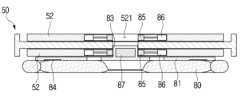
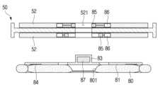
도 12는 본 개시의 하나 이상의 실시 예에 의한 로봇 청소기 스테이션(1)의 홀더 록커(52)에 패드 홀더(81)가 결합된 상태를 나타내는 단면도이다. 도 13은 도 12의 홀더 록커(52)에서 패드 홀더(81)가 분리된 상태를 나타내는 단면도이다.Fig. 12 is a cross-sectional view showing a state in which a pad holder (81) is coupled to a holder locker (52) of a robot cleaner station (1) according to one or more embodiments of the present disclosure. Fig. 13 is a cross-sectional view showing a state in which a pad holder (81) is separated from the holder locker (52) of Fig. 12.
도 12를 참조하면, 홀더 록커(52)는 원판 형상으로 형성될 수 있다. 홀더 록커(52)의 중심에는 록킹 구멍(521)이 형성될 수 있다. 록킹 구멍(521)은 패드 홀더(81)의 고정 돌기(83)가 삽입될 수 있도록 형성된다.Referring to Fig. 12, the holder locker (52) may be formed in a disc shape. A locking hole (521) may be formed in the center of the holder locker (52). The locking hole (521) is formed so that the fixing projection (83) of the pad holder (81) can be inserted.
록킹 구멍(521)의 둘레에는 복수의 금속 블록(85)이 설치될 수 있다. 복수의 금속 블록(85) 각각은 홀더 록커(52)의 반지름 방향으로 일정 거리 왕복 운동할 수 있도록 설치될 수 있다. 복수의 금속 블록(85)은 록킹 구멍(521)의 원주 방향으로 일정 간격으로 배치될 수 있다. 복수의 금속 블록(85)은 각각 액추에이터(86)에 의해 일정 거리 왕복 운동할 수 있다. 예를 들면, 금속 블록(85)은 솔레노이드를 이용하여 이동하도록 형성할 수 있다.A plurality of metal blocks (85) may be installed around the locking hole (521). Each of the plurality of metal blocks (85) may be installed so as to be able to reciprocate a predetermined distance in the radial direction of the holder locker (52). The plurality of metal blocks (85) may be arranged at a predetermined interval in the circumferential direction of the locking hole (521). Each of the plurality of metal blocks (85) may be able to reciprocate a predetermined distance by an actuator (86). For example, the metal blocks (85) may be formed to move using a solenoid.
패드 홀더(81)는 홀더판(82)과 고정 돌기(83)를 포함할 수 있다.The pad holder (81) may include a holder plate (82) and a fixing projection (83).
홀더판(82)은 하면에 걸레 패드(80)를 부착할 수 있도록 형성된다. 홀더판(82)은 걸레 패드(80)에 대응하는 형상으로 형성될 수 있다. 예를 들면, 홀더판(82)은 원판 형상으로 형성될 수 있다. 홀더판(82)은 걸레 패드(80)보다 작거나 유사한 지름을 갖도록 형성될 수 있다.The holder plate (82) is formed so that a mop pad (80) can be attached to the lower surface. The holder plate (82) can be formed in a shape corresponding to the mop pad (80). For example, the holder plate (82) can be formed in a circular shape. The holder plate (82) can be formed to have a diameter smaller than or similar to that of the mop pad (80).
홀더판(82)의 하면에는 복수의 벨크로(84)가 일정 간격으로 설치될 수 있다. 걸레 패드(80)는 복수의 벨크로(84)에 의해 홀더판(82)의 하면에 고정 또는 부착될 수 있다. 걸레 패드(80)를 홀더판(82)의 하면에 부착하면, 걸레 패드 조립체(80A)가 형성된다.A plurality of Velcros (84) can be installed at regular intervals on the lower surface of the holder plate (82). The mop pad (80) can be fixed or attached to the lower surface of the holder plate (82) by the plurality of Velcros (84). When the mop pad (80) is attached to the lower surface of the holder plate (82), a mop pad assembly (80A) is formed.
고정 돌기(83)는 홀더판(82)의 상면의 중심에서 돌출되도록 형성될 수 있다. 고정 돌기(83)는 홀더 록커(52)의 록킹 구멍(521)에 삽입될 수 있도록 형성된다. 고정 돌기(83)는 원기둥 형상으로 형성될 수 있다. 고정 돌기(83)의 내부에는 영구자석(87)이 설치될 수 있다.The fixed projection (83) may be formed to protrude from the center of the upper surface of the holder plate (82). The fixed projection (83) is formed to be inserted into the locking hole (521) of the holder locker (52). The fixed projection (83) may be formed in a cylindrical shape. A permanent magnet (87) may be installed inside the fixed projection (83).
패드 홀더(81)는 고정 돌기(83)의 영구자석(87)과 홀더 록커(52)의 복수의 금속 블록(85) 사이의 자력에 의해 홀더 록커(52)에 고정될 수 있다.The pad holder (81) can be fixed to the holder rocker (52) by the magnetic force between the permanent magnet (87) of the fixed projection (83) and the plurality of metal blocks (85) of the holder rocker (52).
즉, 도 12에 도시된 바와 같이, 패드 홀더(81)의 고정 돌기(83)가 홀더 록커(52)의 록킹 구멍(521)에 삽입된 상태에서, 금속 블록(85)이 록킹 구멍(521)에 인접하면, 고정 돌기(83)의 영구자석(87)과 홀더 록커(52)의 복수의 금속 블록(85) 사이의 자력에 의해 패드 홀더(81)가 홀더 록커(52)에 고정될 수 있다.That is, as shown in Fig. 12, when the fixing projection (83) of the pad holder (81) is inserted into the locking hole (521) of the holder locker (52), and the metal block (85) is adjacent to the locking hole (521), the pad holder (81) can be fixed to the holder locker (52) by the magnetic force between the permanent magnet (87) of the fixing projection (83) and the plurality of metal blocks (85) of the holder locker (52).
도 13에 도시된 바와 같이, 홀더 록커(52)의 복수의 금속 블록(85)이 록킹 구멍(521)으로부터 멀어지면, 고정 돌기(83)의 영구자석(87)과 복수의 금속 블록(85) 사이에 자력이 작용하지 않으므로 패드 홀더(81)가 홀더 록커(52)로부터 분리될 수 있다.As shown in Fig. 13, when the plurality of metal blocks (85) of the holder locker (52) move away from the locking hole (521), the magnetic force does not act between the permanent magnet (87) of the fixed protrusion (83) and the plurality of metal blocks (85), so the pad holder (81) can be separated from the holder locker (52).
이하, 도 14 및 도 15를 참조하여, 본 개시의 하나 이상의 실시 예에 의한 로봇 청소기 시스템(200)에 대해 상세하게 설명한다.Hereinafter, with reference to FIGS. 14 and 15, a robot cleaner system (200) according to one or more embodiments of the present disclosure will be described in detail.
도 14는 본 개시의 하나 이상의 실시 예에 의한 로봇 청소기 시스템(200)을 나타내는 도면이다. 도 15는 본 개시의 하나 이상의 실시 예에 의한 로봇 청소기 시스템(200)을 나타내는 블록도이다.FIG. 14 is a diagram illustrating a robot cleaner system (200) according to one or more embodiments of the present disclosure. FIG. 15 is a block diagram illustrating a robot cleaner system (200) according to one or more embodiments of the present disclosure.
도 14 및 도 15를 참조하면, 본 개시의 하나 이상의 실시 예에 의한 로봇 청소기 시스템(200)은 로봇 청소기 스테이션(1)과 로봇 청소기(100)를 포함할 수 있다.Referring to FIGS. 14 and 15, a robot cleaner system (200) according to one or more embodiments of the present disclosure may include a robot cleaner station (1) and a robot cleaner (100).
이하의 설명에서, 설명의 편의를 위해 걸레 패드(80)와 패드 홀더(81)를 포함하는 걸레 패드 조립체(80A)를 걸레 패드(80)라 칭한다. 즉, 사용된 걸레 패드(80')는 사용된 걸레 패드 조립체(80A)를 말하고, 세척된 걸레 패드(80)는 세척된 걸레 패드 조립체(80A)를 말한다.In the following description, for convenience of explanation, a mop pad assembly (80A) including a mop pad (80) and a pad holder (81) is referred to as a mop pad (80). That is, a used mop pad (80') refers to a used mop pad assembly (80A), and a washed mop pad (80) refers to a washed mop pad assembly (80A).
로봇 청소기 스테이션(1)은 로봇 청소기(100)가 사용된 걸레 패드(80)를 수거하고, 세척된 걸레 패드(80)를 로봇 청소기(100)에 공급할 수 있도록 형성된다. 로봇 청소기 스테이션(1)은 사용된 걸레 패드(80')를 세척하고, 세척된 걸레 패드(80)를 로봇 청소기(100)에 공급할 수 있도록 형성된다.The robot cleaner station (1) is formed so that the robot cleaner (100) can collect the used mop pad (80) and supply the washed mop pad (80) to the robot cleaner (100). The robot cleaner station (1) is formed so that the used mop pad (80') can be washed and the washed mop pad (80) can be supplied to the robot cleaner (100).
로봇 청소기 스테이션(1)은 베이스(10), 패드 세척장치(20), 패드 이동장치(30)를 포함할 수 있다. 베이스(10), 패드 세척장치(20), 및 패드 이동장치(30)는 상술하였으므로 상세한 설명은 생략한다.The robot cleaner station (1) may include a base (10), a pad washing device (20), and a pad moving device (30). Since the base (10), the pad washing device (20), and the pad moving device (30) have been described above, a detailed description thereof will be omitted.
로봇 청소기 스테이션(1)은 위치 센서(91), 통신부(93), 및 프로세서(90)를 포함할 수 있다.The robot cleaner station (1) may include a position sensor (91), a communication unit (93), and a processor (90).
위치 센서(91)는 승강 프레임(40)의 위치, 즉 승강 프레임(40)의 수직 방향의 위치를 검출할 수 있도록 형성된다. 예를 들면, 위치 센서(92)는 승강 프레임(40)이 2곳의 위치, 즉 상부 위치와 하부 위치 중 어디에 위치하는지를 인식하도록 형성될 수 있다.The position sensor (91) is formed so as to be able to detect the position of the lifting frame (40), i.e., the vertical position of the lifting frame (40). For example, the position sensor (92) can be formed so as to recognize which of two positions the lifting frame (40) is located in, i.e., the upper position and the lower position.
위치 센서(91)는 복수의 물리적 센서로 구현될 수 있다. 또는, 위치 센서(92)는 모터(65)의 회전 각도를 이용하여 소프트웨어적으로 구현될 수 있다.The position sensor (91) may be implemented with multiple physical sensors. Alternatively, the position sensor (92) may be implemented in software using the rotation angle of the motor (65).
통신부(93)는 로봇 청소기(100)와 무선으로 통신할 수 있도록 형성된다. 예를 들면, 통신부(93)는 로봇 청소기(100)로 걸레 패드(80)의 준비가 완료되었다는 신호를 전송할 수 있다. 또한, 통신부(93)는 로봇 청소기(100)로부터 걸레 패드(80)의 장착이 완료되었다는 신호 및 걸레 패드(80)의 분리가 완료되었다는 신호를 수신할 수 있다.The communication unit (93) is formed to be able to communicate wirelessly with the robot cleaner (100). For example, the communication unit (93) can transmit a signal to the robot cleaner (100) that the mop pad (80) is ready. In addition, the communication unit (93) can receive a signal from the robot cleaner (100) that the mounting of the mop pad (80) is complete and a signal that the detachment of the mop pad (80) is complete.
통신부(93)는 스마트폰, 태블릿 컴퓨터 등과 같은 모바일 기기와 통신할 수 있도록 형성될 수 있다. 통신부(93)는 Blutooth, WiFi, 4G, 5G 등 다양한 이동통신방식에 의해 모바일 기기와 연결될 수 있다.The communication unit (93) may be configured to communicate with mobile devices such as smartphones, tablet computers, etc. The communication unit (93) may be connected to the mobile device through various mobile communication methods such as Bluetooth, WiFi, 4G, and 5G.
프로세서(90)는 로봇 청소기 스테이션(1)을 제어하도록 형성될 수 있다. 프로세서(90)는 패드 이동장치(30)의 모터(34)를 제어하여 승강 프레임(40)을 2곳의 위치, 즉 상부 위치와 하부 위치 중 한 곳에 위치시킬 수 있다. 프로세서(90)는 패드 세척장치(20)를 제어하여 승강 프레임(40)에 고정된 걸레 패드(80)를 세척할 수 있다.The processor (90) may be configured to control the robot cleaner station (1). The processor (90) may control the motor (34) of the pad moving device (30) to position the lifting frame (40) in one of two positions, i.e., the upper position and the lower position. The processor (90) may control the pad washing device (20) to wash the mop pad (80) fixed to the lifting frame (40).
프로세서(90)는 위치 센서(91)로부터 전송되는 신호를 이용하여 승강 프레임(40)의 위치를 인식할 수 있다. 즉, 프로세서(90)는 위치 센서(91)로부터 전송되는 신호를 이용하여 승강 프레임(40)이 상부 위치와 하부 위치 중 어디에 위치하고 있는지를 인식할 수 있다.The processor (90) can recognize the position of the lifting frame (40) using the signal transmitted from the position sensor (91). That is, the processor (90) can recognize whether the lifting frame (40) is located in the upper position or the lower position using the signal transmitted from the position sensor (91).
프로세서(90)는 패드 이동장치(30)와 패드 세척장치(20)를 제어하여, 승강 프레임(40)에 고정된 사용된 걸레 패드(80')를 세척할 수 있다.The processor (90) controls the pad moving device (30) and the pad washing device (20) to wash a used mop pad (80') fixed to the lifting frame (40).
구체적으로, 프로세서(90)는 패드 이동장치(30)를 제어하여 사용된 걸레 패드(80')가 고정된 승강 프레임(40)을 하부 위치에 위치시키고, 패드 세척장치(20)를 제어하여 승강 프레임(40)에 고정된 사용된 걸레 패드(80')를 세척시킬 수 있다.Specifically, the processor (90) controls the pad moving device (30) to position the lifting frame (40) to which the used mop pad (80') is fixed to a lower position, and controls the pad washing device (20) to wash the used mop pad (80') fixed to the lifting frame (40).
로봇 청소기(100)는 피청소면을 자율 주행할 수 있도록 형성된다. 로봇 청소기(100)는 로봇 청소기 스테이션(1)으로부터 세척된 걸레 패드(80)를 공급받을 수 있도록 형성된다.The robot cleaner (100) is formed so that it can autonomously move around the surface to be cleaned. The robot cleaner (100) is formed so that it can receive a washed mop pad (80) from the robot cleaner station (1).
로봇 청소기(100)는 로봇 청소기 스테이션(1)에서 공급받은 걸레 패드(80)를 이용하여 피청소면을 걸레질할 수 있다.The robot cleaner (100) can mop the surface to be cleaned using a mop pad (80) supplied from the robot cleaner station (1).
걸레질이 완료되면, 로봇 청소기(100)는 사용된 걸레 패드(80')를 로봇 청소기 스테이션(1)에 반납하고, 세척된 걸레 패드(80)를 공급받을 수 있도록 형성된다. 즉, 로봇 청소기(100)는 로봇 청소기 스테이션(1)을 이용하여 사용된 걸레 패드(80')를 세척된 걸레 패드(80)와 교체할 수 있도록 형성된다.When mopping is completed, the robot cleaner (100) is configured to return the used mop pad (80') to the robot cleaner station (1) and receive a washed mop pad (80). That is, the robot cleaner (100) is configured to be able to replace the used mop pad (80') with a washed mop pad (80) using the robot cleaner station (1).
로봇 청소기(100)는 이동장치(101), 위치인식센서(102), 흡입장치(103), 걸레질 장치(104), 걸레 패드 착탈장치(105), 로봇 통신부(106), 로봇 프로세서(109)를 포함할 수 있다.A robot vacuum cleaner (100) may include a moving device (101), a position recognition sensor (102), a suction device (103), a mopping device (104), a mop pad attachment/detachment device (105), a robot communication unit (106), and a robot processor (109).
이동장치(101)는 피청소면에서 로봇 청소기(100)를 이동시킬 수 있도록 형성될 수 있다. 예를 들면, 이동장치(101)는 한 쌍의 바퀴를 포함할 수 있다. 한 쌍의 바퀴는 로봇 청소기(100)의 좌측면과 우측면에 회전 가능하게 설치될 수 있다.The moving device (101) may be formed to be able to move the robot cleaner (100) on the surface to be cleaned. For example, the moving device (101) may include a pair of wheels. The pair of wheels may be rotatably installed on the left and right sides of the robot cleaner (100).
위치인식센서(102)는 로봇 청소기(100)가 자기의 위치를 인식할 수 있도록 형성된다. 로봇 청소기(100)는 위치인식센서(102)를 이용하여 자기의 위치를 인식할 수 있다. 예를 들면, 위치인식센서(102)로는 이미지 센서, 라이다 센서 등과 같이 로봇 청소기(100)의 현재 위치를 인식할 수 있는 센서가 사용될 수 있다.The position recognition sensor (102) is formed so that the robot cleaner (100) can recognize its own position. The robot cleaner (100) can recognize its own position using the position recognition sensor (102). For example, a sensor that can recognize the current position of the robot cleaner (100), such as an image sensor or a lidar sensor, can be used as the position recognition sensor (102).
흡입장치(103)는 흡입력을 발생시켜 피청소면의 오물을 수거할 수 있도록 형성될 수 있다. 예를 들면, 흡입장치(103)는 흡입 모터와 집진장치를 포함할 수 있다. 흡입 모터는 흡입력을 발생시키도록 형성될 수 있다. 집진장치는 로봇 청소기(100)의 하부에 피청소면을 마주하도록 마련된 흡입 노즐과 연결될 수 있다. 따라서, 흡입 모터가 작동하면, 피청소면의 오물이 흡입 노즐을 통해 집진장치로 흡입될 수 있다. 집진장치는 흡입 모터의 흡입력에 의해 흡입 노즐을 통해 공기와 함께 흡입되는 오물을 분리하여 수거할 수 있도록 형성될 수 있다.The suction device (103) may be formed to generate a suction force to collect waste from a surface to be cleaned. For example, the suction device (103) may include a suction motor and a dust collector. The suction motor may be formed to generate a suction force. The dust collector may be connected to a suction nozzle provided at the bottom of the robot cleaner (100) to face the surface to be cleaned. Accordingly, when the suction motor operates, waste from the surface to be cleaned may be sucked into the dust collector through the suction nozzle. The dust collector may be formed to separate and collect waste sucked together with air through the suction nozzle by the suction force of the suction motor.
걸레질 장치(104)는 걸레 패드(80)를 회전시켜 피청소면을 걸레질할 수 있도록 형성된다. 걸레질 장치(104)는 로봇 청소기(100)의 하면에 마련될 수 있다. 걸레질 장치(104)는 걸레 패드(80)를 피청소면에 접촉시킨 상태에서 걸레 패드(80)를 회전시킬 수 있도록 형성된다. 본 실시 예의 경우에는 걸레질 장치(104)는 2개의 걸레 패드(80)를 회전시킬 수 있도록 형성된다.The mopping device (104) is formed so as to be able to mop the surface to be cleaned by rotating the mop pad (80). The mopping device (104) may be provided on the lower surface of the robot cleaner (100). The mopping device (104) is formed so as to be able to rotate the mop pad (80) while the mop pad (80) is in contact with the surface to be cleaned. In the present embodiment, the mopping device (104) is formed so as to be able to rotate two mop pads (80).
걸레질 장치(104)는 걸레 패드(80)를 상하 방향으로 일정 거리 이동시킬 수 있도록 형성된다. 즉, 걸레질 장치(104)는 걸레 패드(80)를 상승 위치와 하강 위치 중 한 곳에 위치시키도록 형성될 수 있다.The mopping device (104) is formed so as to be able to move the mop pad (80) a certain distance in the up-and-down direction. That is, the mopping device (104) can be formed so as to position the mop pad (80) in one of the raised position and the lowered position.
걸레 패드 착탈장치(105)는 걸레 패드(80)를 로봇 청소기(100)의 하면의 걸레질 장치(104)에 장착시킬 수 있도록 형성된다. 또한, 걸레 패드 착탈장치(105)는 걸레질 장치(104)에 장착된 걸레 패드(80)를 분리시킬 수 있도록 형성된다. 본 실시 예의 경우에는 걸레 패드 착탈장치(105)는 2개의 걸레 패드(80)를 장착 및 탈착시킬 수 있도록 형성된다.The mop pad attachment/detachment device (105) is formed so that the mop pad (80) can be attached to the mopping device (104) on the lower side of the robot cleaner (100). In addition, the mop pad attachment/detachment device (105) is formed so that the mop pad (80) attached to the mopping device (104) can be separated. In the case of the present embodiment, the mop pad attachment/detachment device (105) is formed so that two mop pads (80) can be attached and detached.
로봇 통신부(106)는 로봇 청소기 스테이션(1)과 무선으로 통신할 수 있도록 형성될 수 있다. 예를 들면, 로봇 청소기(100)가 걸레 패드(80)의 장착을 완료하면, 로봇 통신부(106)는 걸레 패드 장착 신호를 로봇 청소기 스테이션(1)으로 전송할 수 있다. 또한, 로봇 청소기(100)가 걸레 패드(80)의 분리를 완료하면, 로봇 통신부(106)는 걸레 패드 분리 신호를 로봇 청소기 스테이션(1)으로 전송할 수 있다.The robot communication unit (106) may be configured to communicate wirelessly with the robot cleaner station (1). For example, when the robot cleaner (100) completes mounting the mop pad (80), the robot communication unit (106) may transmit a mop pad mounting signal to the robot cleaner station (1). In addition, when the robot cleaner (100) completes detaching the mop pad (80), the robot communication unit (106) may transmit a mop pad detachment signal to the robot cleaner station (1).
로봇 통신부(106)는 스마트폰, 태블릿 컴퓨터 등과 같은 모바일 기기와 통신할 수 있도록 형성될 수 있다. 로봇 통신부(106)는 Blutooth, WiFi, 4G, 5G 등 다양한 이동통신방식에 의해 모바일 기기와 연결될 수 있다.The robot communication unit (106) may be configured to communicate with mobile devices such as smartphones, tablet computers, etc. The robot communication unit (106) may be connected to the mobile device through various mobile communication methods such as Bluetooth, WiFi, 4G, and 5G.
로봇 프로세서(109)는 로봇 청소기(100)를 제어하도록 형성된다. 예를 들면, 로봇 프로세서(109)는 이동장치(101), 위치인식센서(102), 흡입장치(103), 걸레질 장치(104), 걸레 패드 착탈장치(105), 로봇 통신부(106)를 제어하도록 형성될 수 있다.The robot processor (109) is configured to control the robot cleaner (100). For example, the robot processor (109) may be configured to control a moving device (101), a position recognition sensor (102), a suction device (103), a mopping device (104), a mop pad attachment/detachment device (105), and a robot communication unit (106).
로봇 프로세서(109)는 이동장치(101)를 제어하여 로봇 청소기(100)를 이동시킬 수 있다. 로봇 프로세서(109)는 위치인식센서(102)를 이용하여 로봇 청소기(100)의 현재 위치를 인식할 수 있다. 로봇 프로세서(109)는 위치인식센서(102)와 이동장치(101)를 이용하여 로봇 청소기(100)를 임의의 위치로 이동시킬 수 있다.The robot processor (109) can control the moving device (101) to move the robot cleaner (100). The robot processor (109) can recognize the current location of the robot cleaner (100) using the position recognition sensor (102). The robot processor (109) can move the robot cleaner (100) to an arbitrary location using the position recognition sensor (102) and the moving device (101).
로봇 프로세서(109)는 흡입장치(103)를 제어하여 피청소면의 오물을 흡입할 수 있다. 로봇 프로세서(109)는 이동장치(101)와 흡입장치(103)를 제어하여 로봇 청소기(100)를 이동시키면서 피청소면의 오물을 흡입할 수 있다.The robot processor (109) can control the suction device (103) to suck up dirt from the surface to be cleaned. The robot processor (109) can control the moving device (101) and the suction device (103) to move the robot cleaner (100) and suck up dirt from the surface to be cleaned.
로봇 프로세서(109)는 걸레질 장치(104)를 제어하여 걸레 패드(80)를 회전시켜 피청소면을 걸레질할 수 있다. 로봇 프로세서(109)는 이동장치(101)와 걸레질 장치(104)를 제어하여 로봇 청소기(100)를 이동시키면서 걸레 패드(80)를 회전시켜 피청소면을 걸레질할 수 있다.The robot processor (109) controls the mopping device (104) to rotate the mopping pad (80) to mop the surface to be cleaned. The robot processor (109) controls the moving device (101) and the mopping device (104) to move the robot cleaner (100) and rotate the mopping pad (80) to mop the surface to be cleaned.
로봇 프로세서(109)는 걸레질 장치(104)를 제어하여 걸레 패드(80)를 상승 위치와 하강 위치 중 한 곳에 위치시킬 수 있다.The robot processor (109) can control the mopping device (104) to position the mop pad (80) in either a raised position or a lowered position.
로봇 프로세서(109)는 걸레 패드 착탈장치(105)를 제어하여 걸레 패드(80)를 걸레질 장치(104)에 장착할 수 있다. 또한, 로봇 프로세서(109)는 걸레 패드 착탈장치(105)를 제어하여 걸레질 장치(104)에 장착된 걸레 패드(80)를 분리할 수 있다.The robot processor (109) can control the mop pad attachment/detachment device (105) to attach the mop pad (80) to the mopping device (104). In addition, the robot processor (109) can control the mop pad attachment/detachment device (105) to detach the mop pad (80) attached to the mopping device (104).
이하, 로봇 청소기 스테이션(1)과 로봇 청소기(100)를 포함하는 로봇 청소기 시스템(200)의 걸레 패드의 교체 방법에 대해 도 16a 내지 도 16h를 참조하여 상세하게 설명한다.Hereinafter, a method for replacing a mop pad of a robot cleaner system (200) including a robot cleaner station (1) and a robot cleaner (100) will be described in detail with reference to FIGS. 16a to 16h.
도 16a 내지 도 16h는 본 개시의 하나 이상의 실시 예에 의한 로봇 청소기 시스템(200)에 의한 걸레 패드(80)의 교체 방법을 설명하기 위한 도면이다.FIGS. 16A to 16H are drawings for explaining a method of replacing a mop pad (80) by a robot cleaner system (200) according to one or more embodiments of the present disclosure.
이하의 설명에서, 설명의 편의를 위해 걸레 패드(80)와 패드 홀더(81)를 포함하는 걸레 패드 조립체(80A)를 걸레 패드(80)라 칭한다. 즉, 사용된 걸레 패드(80')는 사용된 걸레 패드 조립체(80A)를 말하고, 세척된 걸레 패드(80)는 세척된 걸레 패드 조립체(80A)를 말한다.In the following description, for convenience of explanation, a mop pad assembly (80A) including a mop pad (80) and a pad holder (81) is referred to as a mop pad (80). That is, a used mop pad (80') refers to a used mop pad assembly (80A), and a washed mop pad (80) refers to a washed mop pad assembly (80A).
로봇 청소기(100)는 걸레질을 수행한 후, 로봇 청소기 스테이션(1)으로 진입하여 베이스(10)의 상면에 위치한다. 이때, 로봇 청소기(100)의 걸레질 장치(104)에 장착된 사용된 걸레 패드(80')가 베이스(10)의 패드 세척장치(20) 위에 위치하게 된다. 로봇 프로세서(109)는 걸레 패드 착탈장치(105)를 제어하여 걸레질 장치(104)에 장착된 사용된 걸레 패드(80')를 분리한다. 그러면, 도 16a에 도시된 바와 같이 분리된 사용된 걸레 패드(80')는 패드 세척장치(20)의 패드 안치부(21)에 위치하게 된다.After performing mopping, the robot cleaner (100) enters the robot cleaner station (1) and is positioned on the upper surface of the base (10). At this time, the used mop pad (80') mounted on the mopping device (104) of the robot cleaner (100) is positioned on the pad washing device (20) of the base (10). The robot processor (109) controls the mop pad attachment/detachment device (105) to detach the used mop pad (80') mounted on the mopping device (104). Then, as shown in FIG. 16a, the detached used mop pad (80') is positioned on the pad mounting portion (21) of the pad washing device (20).
도 16a는 로봇 청소기(100)에 의해 사용된 걸레 패드(80')가 로봇 청소기 스테이션(1)의 패드 세척장치(20)의 패드 안치부(21)에 놓인 상태를 나타내는 도면이다.FIG. 16a is a drawing showing a state in which a mop pad (80') used by a robot cleaner (100) is placed on a pad holder (21) of a pad washing device (20) of a robot cleaner station (1).
도 16a를 참조하면, 패드 안치부(21) 위에 사용된 걸레 패드(80')가 위치한다. 이때, 패드 안치부(21)의 아래에 위치하는 패드 고정장치(23)는 사용된 걸레 패드(80')의 아래에 위치하게 된다. 구체적으로, 패드 고정장치(23)의 삽입 돌기(232)는 원위치에 위치하고 있다. 따라서, 사용된 걸레 패드(80')는 패드 고정장치(23)에 의해 패드 안치부(21)에 고정되지 않는다.Referring to Fig. 16a, a used mop pad (80') is positioned on the pad fixing portion (21). At this time, the pad fixing device (23) positioned below the pad fixing portion (21) is positioned below the used mop pad (80'). Specifically, the insertion protrusion (232) of the pad fixing device (23) is positioned in the original position. Therefore, the used mop pad (80') is not fixed to the pad fixing portion (21) by the pad fixing device (23).
패드 고정장치(23)는 걸레 패드(80, 80')를 패드 안치부(21)에 고정시킬 수 있도록 형성된다. 패드 안치부(21)는 중앙에 형성된 관통공(211)을 포함한다. 패드 고정장치(23)는 이동판(231)과 이동판(231)의 중심에서 돌출되는 삽입 돌기(232)를 포함할 수 있다. 삽입 돌기(232)는 패드 안치부(21)의 관통공(211)에 삽입될 수 있도록 형성된다. 삽입 돌기(232)의 상부에는 금속편(233)이 설치될 수 있다.The pad fixing device (23) is formed so as to be able to fix the mop pad (80, 80') to the pad fixing portion (21). The pad fixing portion (21) includes a through hole (211) formed in the center. The pad fixing device (23) may include a moving plate (231) and an insertion projection (232) protruding from the center of the moving plate (231). The insertion projection (232) is formed so as to be inserted into the through hole (211) of the pad fixing portion (21). A metal piece (233) may be installed on the upper portion of the insertion projection (232).
이동판(231)은 수직 방향으로 이동할 수 있도록 형성된다. 삽입 돌기(232)는 이동판(231)에 의해 원위치와 삽입 위치 중 한 곳에 위치할 수 있다.The moving plate (231) is formed so as to be able to move in a vertical direction. The insertion projection (232) can be positioned in one of the original position and the inserted position by the moving plate (231).
삽입 돌기(232)가 원위치에 위치하면, 삽입 돌기(232)의 상단이 걸레 패드(80')의 아래, 즉 패드 안치부(21)의 상면과 동일한 높이나 그 아래에 위치한다. 삽입 돌기(232)가 원위치에 위치하면, 걸레 패드(80')는 패드 안치부(21)에 고정되지 않는다.When the insertion protrusion (232) is positioned in the original position, the upper end of the insertion protrusion (232) is positioned below the mop pad (80'), that is, at the same height as or below the upper surface of the pad mounting portion (21). When the insertion protrusion (232) is positioned in the original position, the mop pad (80') is not fixed to the pad mounting portion (21).
삽입 돌기(232)가 삽입 위치에 위치하면, 삽입 돌기(232)가 패드 안치부(21)의 관통공(211)에서 돌출되고 걸레 패드(80')의 걸레 구멍(801)에 삽입되어 삽입 돌기(232)의 상단이 패드 홀더(81)의 분리 자석(85)에 인접하거나 접촉하게 된다. 삽입 돌기(232)가 삽입 위치에 위치하면, 걸레 패드(80')는 패드 안치부(21)에 고정된다.When the insertion projection (232) is positioned at the insertion position, the insertion projection (232) protrudes from the through hole (211) of the pad mounting portion (21) and is inserted into the mop hole (801) of the mop pad (80') so that the upper end of the insertion projection (232) is adjacent to or in contact with the separating magnet (85) of the pad holder (81). When the insertion projection (232) is positioned at the insertion position, the mop pad (80') is fixed to the pad mounting portion (21).
또한, 회전판(50)의 상면, 즉 제1면의 제1홀더 록커(52-1)에는 세척된 걸레 패드(80)가 고정되어 있고, 회전판(50)의 하면, 즉 제2면의 제2홀더 록커(52-2)에는 걸레 패드(80)가 고정되어 있지 않다.In addition, a washed mop pad (80) is fixed to the first holder locker (52-1) on the upper surface of the turntable (50), that is, the first surface, and a mop pad (80) is not fixed to the second holder locker (52-2) on the lower surface of the turntable (50), that is, the second surface.
이 상태에서, 프로세서(90)는 승강장치(60)를 제어하여 승강 프레임(40)을 하강시켜 사용된 걸레 패드(80')를 회전판(50)의 하면, 즉 제2면에 고정시킨다. 이 상태가 도 16b에 도시되어 있다.In this state, the processor (90) controls the lifting device (60) to lower the lifting frame (40) and fix the used mop pad (80') to the lower surface, i.e., the second surface, of the rotating plate (50). This state is illustrated in Fig. 16b.
도 16b는 승강 프레임(40)이 하강하여 패드 세척장치(20)의 패드 안치부(21)에 놓인 사용된 걸레 패드(80')를 회전판(50)의 제2면에 고정시킨 상태를 나타내는 도면이다.Figure 16b is a drawing showing a state in which the lifting frame (40) is lowered and a used mop pad (80') placed on the pad mounting portion (21) of the pad washing device (20) is fixed to the second surface of the rotating plate (50).
도 16b를 참조하면, 승강 프레임(40)의 회전판(50)의 하면, 즉 제2면에 설치된 제2홀더 록커(52-2)가 사용된 걸레 패드(80')를 고정하고 있다. 구체적으로, 승강 프레임(40)이 하강하면, 사용된 걸레 패드(80')의 고정 돌기(83)가 회전판(50)의 제2면에 설치된 제2홀더 록커(52-2)의 록킹 구멍(521)에 삽입된다. 그러면, 록킹 구멍(521)에 마련된 복수의 볼 스프링(53)의 볼(531)이 고정 돌기(83)의 후킹 홈(831)에 삽입되므로, 사용된 걸레 패드(80')가 제2홀더 록커(52-2)에 고정된다.Referring to Fig. 16b, the second holder locker (52-2) installed on the lower surface, i.e., the second surface, of the rotary plate (50) of the lifting frame (40) fixes the used mop pad (80'). Specifically, when the lifting frame (40) is lowered, the fixing projection (83) of the used mop pad (80') is inserted into the locking hole (521) of the second holder locker (52-2) installed on the second surface of the rotary plate (50). Then, the balls (531) of the plurality of ball springs (53) provided in the locking hole (521) are inserted into the hooking grooves (831) of the fixing projections (83), so that the used mop pad (80') is fixed to the second holder locker (52-2).
이때, 패드 고정장치(23)의 삽입 돌기(232)는 원위치를 유지하고 있다.At this time, the insertion projection (232) of the pad fixing device (23) maintains its original position.
이 상태에서, 프로세서(90)는 승강장치(60)를 제어하여 승강 프레임(40)을 상승시킨다. 승강 프레임(40)이 상승하면, 회전판(50)의 회전 돌기(71)가 간섭 레버(75)에 간섭되어 회전판(50)이 120도 이상 회전하게 된다. 승강 프레임(40)이 계속해서 상승하여 상부 위치에 위치하면, 회전판(50)은 복수의 밀대(79)에 의해 약 180도 회전한 상태가 된다. 이 상태가 도 16c에 도시되어 있다.In this state, the processor (90) controls the elevator device (60) to raise the elevator frame (40). When the elevator frame (40) rises, the rotation protrusion (71) of the rotary plate (50) interferes with the interference lever (75), causing the rotary plate (50) to rotate more than 120 degrees. When the elevator frame (40) continues to rise and is positioned at the upper position, the rotary plate (50) is rotated approximately 180 degrees by the plurality of push rods (79). This state is illustrated in Fig. 16c.
도 16c는 승강 프레임(40)이 상승하여 사용된 걸레 패드(80')가 승강 프레임(40)의 위에 위치하고, 세척된 걸레 패드(80)가 승강 프레임(40)의 아래에 위치한 상태를 나타내는 도면이다.Figure 16c is a drawing showing a state in which the lifting frame (40) is raised, the used mop pad (80') is positioned above the lifting frame (40), and the washed mop pad (80) is positioned below the lifting frame (40).
도 16c를 참조하면, 회전판(50)의 제2면의 제2홀더 록커(52-2)에 고정된 사용된 걸레 패드(80')는 승강 프레임(40)의 상측에 위치하고, 회전판(50)의 제1면의 제1홀더 록커(52-1)에 고정된 세척된 걸레 패드(80)는 승강 프레임(40)의 하측에 위치하게 된다. 즉, 세척된 걸레 패드(80)가 패드 세척장치(20)를 마주한다.Referring to Fig. 16c, the used mop pad (80') fixed to the second holder locker (52-2) of the second surface of the turntable (50) is positioned on the upper side of the lifting frame (40), and the washed mop pad (80) fixed to the first holder locker (52-1) of the first surface of the turntable (50) is positioned on the lower side of the lifting frame (40). That is, the washed mop pad (80) faces the pad washing device (20).
이 상태에서 프로세서(90)는 승강장치(60)를 제어하여 승강 프레임(40)을 하강시킨다. 승강 프레임(40)이 하강하는 동안 회전판(50)의 회전 돌기(71)가 간섭 레버(75)에 접촉하게 된다. 그러나, 회전 돌기(71)는 승강 프레임(40)의 멈춤 홈(72)에 삽입되어 있으므로, 회전판(50)이 회전하지 않고, 간섭 레버(75)의 레버(77)가 아래로 굽혀지게 된다.In this state, the processor (90) controls the elevator device (60) to lower the elevator frame (40). While the elevator frame (40) is lowered, the rotation protrusion (71) of the rotary plate (50) comes into contact with the interference lever (75). However, since the rotation protrusion (71) is inserted into the stop groove (72) of the elevator frame (40), the rotary plate (50) does not rotate, and the lever (77) of the interference lever (75) is bent downward.
승강 프레임(40)이 하부 위치에 위치하면, 세척된 걸레 패드(80)는 패드 세척장치(20)의 패드 안치부(21)에 위치하게 된다. 이 상태에서, 프로세서(90)는 패드 세척장치(20)의 패드 고정장치(23)를 제어하여 삽입 돌기(232)를 삽입 위치로 이동시킨다. 그러면, 삽입 돌기(232)가 세척된 걸레 패드(80)의 걸레 구멍(801)에 삽입되어 패드 홀더(81)와 자력으로 결합된다. 이 상태가 도 16d에 도시되어 있다.When the lifting frame (40) is positioned in the lower position, the washed mop pad (80) is positioned in the pad fixing portion (21) of the pad washing device (20). In this state, the processor (90) controls the pad fixing device (23) of the pad washing device (20) to move the insertion projection (232) to the insertion position. Then, the insertion projection (232) is inserted into the mop hole (801) of the washed mop pad (80) and is magnetically coupled with the pad holder (81). This state is illustrated in Fig. 16d.
도 16d는 승강 프레임(40)이 하강하여 세척된 걸레 패드(80)가 패드 세척장치(20)의 패드 안치부(21)에 위치한 상태를 나타내는 도면이다.Figure 16d is a drawing showing a state in which the lifting frame (40) is lowered and the washed mop pad (80) is positioned in the pad mounting portion (21) of the pad washing device (20).
도 16d를 참조하면, 승강 프레임(40)은 하부 위치에 위치하고, 회전판(50)의 제1홀더 록커(52-1)에 고정된 세척된 걸레 패드(80)는 패드 안치부(21)에 위치한다. 세척된 걸레 패드(80)의 패드 홀더(81)는 패드 세척장치(20)의 삽입 돌기(232)와 자력으로 결합된 상태이다.Referring to Fig. 16d, the lifting frame (40) is positioned at the lower position, and the washed mop pad (80) fixed to the first holder rocker (52-1) of the rotating plate (50) is positioned in the pad holder (21). The pad holder (81) of the washed mop pad (80) is magnetically coupled to the insertion projection (232) of the pad washing device (20).
이 상태에서, 프로세서(90)는 승강장치(60)를 제어하여 승강 프레임(40)을 상승시킨다. 이때, 세척된 걸레 패드(80)의 패드 홀더(81)는 패드 세척장치(20)의 삽입 돌기(232)와 자력으로 결합된 상태이므로, 승강 프레임(40)이 상승하면, 세척된 걸레 패드(80)는 회전판(50)의 제1홀더 록커(52-1)에서 분리되어 패드 안치부(21) 위에 위치하게 된다.In this state, the processor (90) controls the lifting device (60) to raise the lifting frame (40). At this time, the pad holder (81) of the washed mop pad (80) is magnetically coupled to the insertion protrusion (232) of the pad washing device (20), so when the lifting frame (40) rises, the washed mop pad (80) is separated from the first holder rocker (52-1) of the rotating plate (50) and positioned on the pad placement part (21).
승강 프레임(40)이 상승하면, 회전판(50)의 회전 돌기(71)가 간섭 레버(75)에 간섭되어 회전판(50)이 120도 이상 회전하게 된다. 승강 프레임(40)이 계속 상승하여 상부 위치에 위치하면, 회전판(50)은 복수의 밀대(79)에 의해 약 180도 회전한 상태가 된다.When the lifting frame (40) rises, the rotating projection (71) of the turntable (50) interferes with the interference lever (75), causing the turntable (50) to rotate more than 120 degrees. When the lifting frame (40) continues to rise and is positioned at the upper position, the turntable (50) is rotated approximately 180 degrees by a plurality of push rods (79).
승강 프레임(40)이 상승할 때, 프로세서(90)는 패드 고정장치(23)를 제어하여 삽입 돌기(232)를 원위치로 이동시킨다. 그러면, 세척된 걸레 패드(80)의 패드 홀더(81)와 패드 세척장치(20)의 삽입 돌기(232) 사이의 결합이 해제된다. 이 상태가 도 16e에 도시되어 있다.When the lifting frame (40) rises, the processor (90) controls the pad fixing device (23) to move the insertion projection (232) to the original position. Then, the connection between the pad holder (81) of the washed mop pad (80) and the insertion projection (232) of the pad washing device (20) is released. This state is illustrated in Fig. 16e.
도 16e는 승강 프레임(40)이 상승하여 사용된 걸레 패드(80')가 승강 프레임(40)의 아래에 위치하고, 세척된 걸레 패드(80)는 패드 세척장치(20)의 패드 안치부(21) 위에 위치한 상태를 나타낸 도면이다.FIG. 16e is a drawing showing a state in which the lifting frame (40) is raised, the used mop pad (80') is positioned below the lifting frame (40), and the washed mop pad (80) is positioned above the pad holder (21) of the pad washing device (20).
도 16e를 참조하면, 승강 프레임(40)은 상부 위치에 위치하고, 회전판(50)의 제2홀더 록커(52-2)에 고정된 사용된 걸레 패드(80')는 승강 프레임(40)의 하측에 위치하여 패드 세척장치(20)를 마주한다. 패드 안치부(21)에 안치된 세척된 걸레 패드(80)의 패드 홀더(81)는 패드 고정장치(23)의 삽입 돌기(232)와 결합되지 않은 상태이다.Referring to Fig. 16e, the lifting frame (40) is positioned at the upper position, and the used mop pad (80') fixed to the second holder locker (52-2) of the rotating plate (50) is positioned at the lower side of the lifting frame (40) and faces the pad washing device (20). The pad holder (81) of the washed mop pad (80) fixed to the pad fixing portion (21) is not engaged with the insertion projection (232) of the pad fixing device (23).
이 상태에서 프로세서(90)는 통신부(93)를 제어하여 걸레 패드 준비 신호를 로봇 청소기(100)로 전송할 수 있다.In this state, the processor (90) can control the communication unit (93) to transmit a mop pad preparation signal to the robot cleaner (100).
로봇 청소기(100)가 로봇 청소기 스테이션(1)으로부터 걸레 패드 준비 신호를 수신하면, 로봇 청소기(100)는 로봇 청소기 스테이션(1)으로 진입하여 베이스(10)의 패드 안치부(21)에 위치한 세척된 걸레 패드(80)를 장착한다.When the robot cleaner (100) receives a mop pad preparation signal from the robot cleaner station (1), the robot cleaner (100) enters the robot cleaner station (1) and mounts a washed mop pad (80) located in the pad mounting portion (21) of the base (10).
구체적으로, 로봇 프로세서(109)가 로봇 통신부(106)를 통해 로봇 청소기 스테이션(1)으로부터 걸레 패드 준비 신호를 수신하면, 로봇 프로세서(109)는 이동장치(101)를 제어하여 로봇 청소기(100)를 로봇 청소기 스테이션(1)의 베이스(10)로 이동시킨다.Specifically, when the robot processor (109) receives a mop pad preparation signal from the robot cleaner station (1) through the robot communication unit (106), the robot processor (109) controls the moving device (101) to move the robot cleaner (100) to the base (10) of the robot cleaner station (1).
로봇 청소기(100)가 베이스(10)의 상면에 위치하면, 로봇 청소기(100)의 걸레질 장치(104)가 패드 세척장치(20)의 패드 안치부(21) 위에 위치하게 된다. 그러면, 로봇 프로세서(109)는 걸레 패드 착탈장치(105)를 제어하여 걸레 패드(80)를 걸레질 장치(104)에 장착한다.When the robot cleaner (100) is positioned on the upper surface of the base (10), the mopping device (104) of the robot cleaner (100) is positioned on the pad mounting portion (21) of the pad washing device (20). Then, the robot processor (109) controls the mop pad attachment/detachment device (105) to attach the mop pad (80) to the mopping device (104).
걸레 패드(80)의 장착이 완료되면, 로봇 프로세서(109)는 이동장치(101)를 제어하여 로봇 청소기(100)를 로봇 청소기 스테이션(1)의 외부로 이동시키고, 로봇 통신부(106)를 제어하여 걸레 패드 장착 신호를 로봇 청소기 스테이션(1)으로 전송한다.When the installation of the mop pad (80) is completed, the robot processor (109) controls the moving device (101) to move the robot cleaner (100) outside the robot cleaner station (1) and controls the robot communication unit (106) to transmit a mop pad installation signal to the robot cleaner station (1).
그 후, 로봇 프로세서(109)는 로봇 청소기(100)를 제어하여 피청소면의 걸레질을 수행한다.After that, the robot processor (109) controls the robot cleaner (100) to perform mopping of the surface to be cleaned.
로봇 청소기(100)가 세척된 걸레 패드(80)를 장착하고, 로봇 청소기 스테이션(1)을 벗어난 상태가 도 16f에 도시되어 있다.A state in which a robot cleaner (100) is equipped with a washed mop pad (80) and has left the robot cleaner station (1) is shown in FIG. 16f.
도 16f를 참조하면, 회전판(50)의 제2홀더 록커(52-2)에 고정된 사용된 걸레 패드(80')는 패드 세척장치(20)를 마주하고, 패드 세척장치(20)에는 걸레 패드(80)가 존재하지 않는다.Referring to FIG. 16f, the used mop pad (80') fixed to the second holder rocker (52-2) of the turntable (50) faces the pad washing device (20), and the mop pad (80) is not present in the pad washing device (20).
로봇 청소기(100)로부터 걸레 패드 장착 신호를 수신하면, 프로세서(90)는 승강장치(60)를 제어하여 승강 프레임(40)을 하강시킨다. 승강 프레임(40)이 하강하여도 회전판(50)은 회전하지 않으므로, 사용된 걸레 패드(80')는 승강 프레임(40)의 아래에 위치한다.When a signal to mount a mop pad is received from the robot cleaner (100), the processor (90) controls the lifting device (60) to lower the lifting frame (40). Even when the lifting frame (40) is lowered, the turntable (50) does not rotate, so the used mop pad (80') is located below the lifting frame (40).
승강 프레임(40)이 하부 위치에 위치하면, 세척된 걸레 패드(80)는 패드 세척장치(20)의 패드 안치부(21)에 위치하게 된다. 이 상태에서, 프로세서(90)는 패드 세척장치(20)를 제어하여 사용된 걸레 패드(80')를 세척한다. 이 상태가 도 16g에 도시되어 있다.When the lifting frame (40) is positioned in the lower position, the washed mop pad (80) is positioned in the pad holder (21) of the pad washing device (20). In this state, the processor (90) controls the pad washing device (20) to wash the used mop pad (80'). This state is illustrated in Fig. 16g.
도 16g는 하부 위치에 위치한 승강 프레임(40)에 고정된 사용된 걸레 패드(80')를 패드 세척장치(20)가 세척하는 상태를 나타내는 도면이다.FIG. 16g is a drawing showing a state in which a used mop pad (80') fixed to a lifting frame (40) located at a lower position is washed by a pad washing device (20).
도 16g를 참조하면, 패드 세척장치(20)가 사용된 걸레 패드(80')를 세척할 때, 사용된 걸레 패드(80')의 패드 홀더(81)는 패드 고정장치(23)의 삽입 돌기(232)와 결합되지 않은 상태이다. 즉, 패드 세척장치(20)가 사용된 걸레 패드(80')를 세척할 때, 패드 고정장치(23)의 삽입 돌기(232)는 원위치에 위치한다.Referring to FIG. 16g, when the pad washing device (20) washes a used mop pad (80'), the pad holder (81) of the used mop pad (80') is not engaged with the insertion projection (232) of the pad fixing device (23). That is, when the pad washing device (20) washes a used mop pad (80'), the insertion projection (232) of the pad fixing device (23) is located in the original position.
패드 세척장치(20)에 의해 사용된 걸레 패드(80')의 세척이 완료되면, 사용된 걸레 패드(80')는 세척된 걸레 패드(80)가 된다.When the cleaning of the mop pad (80') used by the pad cleaning device (20) is completed, the used mop pad (80') becomes a cleaned mop pad (80).
걸레 패드(80)의 세척이 완료되면, 프로세서(90)는 승강장치(60)를 제어하여 승강 프레임(40)을 상승시킨다. 승강 프레임(40)이 상승하면, 회전판(50)의 회전 돌기(71)가 간섭 레버(75)에 간섭되어 회전판(50)이 120도 이상 회전하게 된다. 승강 프레임(40)이 계속해서 상승하여 상부 위치에 위치하면, 회전판(50)은 복수의 밀대(79)에 의해 약 180도 회전한 상태가 된다. 따라서, 세척된 걸레 패드(80)가 승강 프레임(40)의 상측에 위치하게 된다.When the cleaning of the mop pad (80) is completed, the processor (90) controls the lifting device (60) to raise the lifting frame (40). When the lifting frame (40) rises, the rotating protrusion (71) of the rotating plate (50) interferes with the interference lever (75), causing the rotating plate (50) to rotate more than 120 degrees. When the lifting frame (40) continues to rise and is positioned at the upper position, the rotating plate (50) is rotated approximately 180 degrees by the plurality of push rods (79). Therefore, the washed mop pad (80) is positioned at the upper side of the lifting frame (40).
승강 프레임(40)이 상부 위치에 위치하면, 프로세서(90)는 패드 건조장치(29)를 제어하여 세척된 걸레 패드(80)를 건조시킨다. 이 상태가 도 16h에 도시되어 있다.When the lifting frame (40) is positioned at the upper position, the processor (90) controls the pad drying device (29) to dry the washed mop pad (80). This state is illustrated in Fig. 16h.
도 16h는 상부 위치에 위치한 승강 프레임(40)에 고정된 세척된 걸레 패드(80)가 패드 건조장치(29)에 의해 건조되는 상태를 나타내는 도면이다.FIG. 16h is a drawing showing a state in which a washed mop pad (80) fixed to a lifting frame (40) located at an upper position is dried by a pad drying device (29).
도 16h를 참조하면, 회전판(50)의 제2홀더 록커(52-2)에 고정된 세척된 걸레 패드(80)는 승강 프레임(40)의 상측에 위치하며 패드 건조장치(29)를 마주한다. 따라서, 프로세서(90)에 의해 패드 건조장치(29)가 작동하면, 회전판(50)에 고정된 세척된 걸레 패드(80)가 건조된다. 이때, 승강 프레임(40)의 아래에 위치하는 회전판(50)의 제1홀더 록커(52-1)에는 걸레 패드(80)가 고정되어 있지 않다.Referring to FIG. 16h, the washed mop pad (80) fixed to the second holder locker (52-2) of the turntable (50) is located on the upper side of the lifting frame (40) and faces the pad drying device (29). Therefore, when the pad drying device (29) is operated by the processor (90), the washed mop pad (80) fixed to the turntable (50) is dried. At this time, the mop pad (80) is not fixed to the first holder locker (52-1) of the turntable (50) located below the lifting frame (40).
본 개시의 하나 이상의 실시 예에 의한 로봇 청소기 시스템(200)은 로봇 청소기(100)가 걸레질을 수행하는 동안 로봇 청소기 스테이션(1)은 사용된 걸레 패드(80')를 세척할 수 있다. 따라서, 걸레 패드가 로봇 청소기에 부착되어 있는 상태에서 걸레 패드를 세척하도록 형성된 종래 기술에 의한 로봇 청소기 스테이션에 비해 본 개시의 하나 이상의 실시 예에 의한 로봇 청소기 시스템(200)은 충분한 시간을 들여 사용된 걸레 패드(80')를 세척할 수 있으므로, 사용된 걸레 패드(80')를 확실하게 세척할 수 있다.A robot cleaner system (200) according to one or more embodiments of the present disclosure can wash a used mop pad (80') while a robot cleaner (100) performs mopping. Accordingly, compared to a robot cleaner station according to the prior art that is configured to wash a mop pad while the mop pad is attached to the robot cleaner, the robot cleaner system (200) according to one or more embodiments of the present disclosure can wash a used mop pad (80') in a sufficient amount of time, and thus can reliably wash a used mop pad (80').
또한, 본 개시의 하나 이상의 실시 예에 의한 로봇 청소기 스테이션(1)은 로봇 청소기(100)에서 사용된 걸레 패드(80')를 분리한 후 세척하므로, 걸레 패드(80')에 대해 높은 온도의 열풍 건조와 화학적 소독을 할 수 있다.In addition, the robot cleaner station (1) according to one or more embodiments of the present disclosure separates and washes the mop pad (80') used in the robot cleaner (100), so that high-temperature hot air drying and chemical disinfection can be performed on the mop pad (80').
이하, 도 17 내지 도 20을 참조하여, 본 개시의 하나 이상의 실시 예에 의한 로봇 청소기 스테이션(1')에 대해 상세하게 설명한다.Hereinafter, with reference to FIGS. 17 to 20, a robot cleaner station (1') according to one or more embodiments of the present disclosure will be described in detail.
도 17은 본 개시의 하나 이상의 실시 예에 의한 로봇 청소기 스테이션(1')을 나타내는 사시도이다. 도 18은 도 17의 로봇 청소기 스테이션(1')의 승강판(31)을 나타내는 저면 사시도이다.FIG. 17 is a perspective view showing a robot cleaner station (1') according to one or more embodiments of the present disclosure. FIG. 18 is a bottom perspective view showing a lifting plate (31) of the robot cleaner station (1') of FIG. 17.
도 17을 참조하면, 본 개시의 하나 이상의 실시 예에 의한 패드 이동장치(30)는 승강판(31)과 승강장치(60)를 포함할 수 있다.Referring to FIG. 17, a pad moving device (30) according to one or more embodiments of the present disclosure may include a lifting plate (31) and a lifting device (60).
승강판(31)은 직사각형 형상으로 형성될 수 있다. 승강판(31)은 대략 직사각형의 평판 형상으로 형성될 수 있다. 승강판(31)은 승강장치(60)에 의해 상하로 이동할 수 있도록 형성된다.The elevator plate (31) can be formed in a rectangular shape. The elevator plate (31) can be formed in a roughly rectangular flat plate shape. The elevator plate (31) is formed so that it can move up and down by the elevator device (60).
승강판(31)은 홀더 록커(52)를 포함할 수 있다. 홀더 록커(52)는 승강판(31)의 하면에 설치될 수 있다. 본 실시 예의 경우에는, 도 18에 도시된 바와 같이, 승강판(31)의 하면에 2개의 홀더 록커(52)가 설치될 수 있다.The elevator plate (31) may include a holder locker (52). The holder locker (52) may be installed on the lower surface of the elevator plate (31). In the case of the present embodiment, as shown in FIG. 18, two holder lockers (52) may be installed on the lower surface of the elevator plate (31).
홀더 록커(52)는 걸레 패드(80)를 지지 및 고정할 수 있도록 형성된다. 홀더 록커(52)는 걸레 패드(80)를 선택적으로 잡거나 놓을 수 있도록 형성될 수 있다. 본 실시 예와 같이 걸레 패드(80)가 패드 홀더(81)에 고정된 경우에는, 홀더 록커(52)는 패드 홀더(81)를 선택적으로 잡거나 놓을 수 있도록 형성될 수 있다.The holder locker (52) is formed to support and fix the mop pad (80). The holder locker (52) may be formed to selectively hold or place the mop pad (80). In the case where the mop pad (80) is fixed to the pad holder (81) as in the present embodiment, the holder locker (52) may be formed to selectively hold or place the pad holder (81).
홀더 록커(52)는 상술한 실시 예에 의한 로봇 청소기 스테이션(1)의 홀더 록커(52)와 동일하거나 유사하므로 상세한 설명은 생략한다.The holder locker (52) is identical or similar to the holder locker (52) of the robot cleaner station (1) according to the above-described embodiment, so a detailed description is omitted.
승강장치(60)는 승강판(31)을 상하로 이동시키도록 형성될 수 있다. 즉, 승강판(31)은 승강장치(60)에 의해 베이스(10)의 상면에 대해 수직 방향으로 이동할 수 있다. 승강장치(60)는 승강판(31)을 2곳의 위치, 즉 상부 위치와 하부 위치 중 한 곳에 위치시킬 수 있도록 형성된다.The elevator device (60) can be formed to move the elevator plate (31) up and down. That is, the elevator plate (31) can be moved vertically with respect to the upper surface of the base (10) by the elevator device (60). The elevator device (60) is formed to be able to position the elevator plate (31) in one of two positions, that is, the upper position and the lower position.
승강장치(60)는 한 쌍의 랙 기어(61)를 포함할 수 있다.The elevator device (60) may include a pair of rack gears (61).
한 쌍의 랙 기어(61)는 승강판(31)의 양측면에 설치될 수 있다. 한 쌍의 랙 기어(61)는 승강판(31)에 수직하게 설치될 수 있다. 한 쌍의 랙 기어(61)는 승강판(31)과 일체로 형성될 수 있다. 따라서, 한 쌍의 랙 기어(61)가 이동하면 승강판(31)이 이동할 수 있다.A pair of rack gears (61) can be installed on both sides of the elevator plate (31). A pair of rack gears (61) can be installed vertically on the elevator plate (31). A pair of rack gears (61) can be formed integrally with the elevator plate (31). Therefore, when a pair of rack gears (61) move, the elevator plate (31) can move.
승강판(31)의 상하 이동은 한 쌍의 안내부재에 의해 안내될 수 있다. 한 쌍의 안내부재는 승강판(31)의 좌측과 우측에 설치될 수 있다.The up and down movement of the elevator plate (31) can be guided by a pair of guide members. A pair of guide members can be installed on the left and right sides of the elevator plate (31).
한 쌍의 안내부재는 레일 구조로 형성될 수 있다. 예를 들면, 안내부재는 랙 기어(61)의 측면에 형성된 안내 레일(62)과 랙 기어(61)의 안내 레일(62)을 마주하는 케이스(2)의 측면에 형성된 레일 홈(63)을 포함할 수 있다.A pair of guide members may be formed in a rail structure. For example, the guide member may include a guide rail (62) formed on a side of the rack gear (61) and a rail groove (63) formed on a side of the case (2) facing the guide rail (62) of the rack gear (61).
구체적으로, 케이스(2)의 좌측 내면과 우측 내면 각각에는 레일 홈(63)이 형성되어 있다(도 3 참조). 따라서, 승강판(31)에 설치된 한 쌍의 랙 기어(61)의 안내 레일(62), 즉 좌측 랙 기어(61)의 안내 레일(62)과 우측 랙 기어(61)의 안내 레일(62)을 케이스(2)의 좌측 레일 홈(63)과 우측 레일 홈(63)에 삽입하면, 한 쌍의 랙 기어(61)가 케이스(2)의 내측면을 따라 상하로 이동할 수 있다.Specifically, a rail groove (63) is formed on each of the left inner surface and the right inner surface of the case (2) (see FIG. 3). Accordingly, when the guide rail (62) of a pair of rack gears (61) installed on the elevator plate (31), that is, the guide rail (62) of the left rack gear (61) and the guide rail (62) of the right rack gear (61), are inserted into the left rail groove (63) and the right rail groove (63) of the case (2), the pair of rack gears (61) can move up and down along the inner surface of the case (2).
다시 말하면, 승강판(31)의 양측면에 설치된 한 쌍의 랙 기어(61)의 안내 레일(62)을 케이스(2)의 양측 내면에 형성된 한 쌍의 레일 홈(63)에 삽입하면, 한 쌍의 랙 기어(61)는 케이스(2)의 레일 홈(63)을 따라 상하로 이동할 수 있다. 한 쌍의 랙 기어(61)는 승강판(31)의 양측면에 설치되어 있으므로, 한 쌍의 랙 기어(61)가 상하로 이동하면 승강판(31)도 한 쌍의 랙 기어(61)와 일체로 상하로 이동할 수 있다.In other words, when the guide rails (62) of a pair of rack gears (61) installed on both sides of the elevator plate (31) are inserted into a pair of rail grooves (63) formed on both sides of the inner surface of the case (2), the pair of rack gears (61) can move up and down along the rail grooves (63) of the case (2). Since the pair of rack gears (61) are installed on both sides of the elevator plate (31), when the pair of rack gears (61) move up and down, the elevator plate (31) can also move up and down together with the pair of rack gears (61).
승강장치(60)는 한 쌍의 랙 기어(61)에 치합되는 한 쌍의 피니언(63), 한 쌍의 피니언(63)을 구동하는 구동 기어(64), 및 구동 기어(64)를 회전시키는 모터(65)를 포함할 수 있다.The elevator device (60) may include a pair of pinions (63) that mesh with a pair of rack gears (61), a drive gear (64) that drives the pair of pinions (63), and a motor (65) that rotates the drive gear (64).
한 쌍의 피니언(63), 구동 기어(64), 및 모터(65)는 상술한 실시 예에 의한 로봇 청소기 스테이션(1)의 승강장치(60)와 동일하거나 유사하므로 상세한 설명은 생략한다.A pair of pinions (63), a driving gear (64), and a motor (65) are identical or similar to the lifting device (60) of the robot cleaner station (1) according to the above-described embodiment, so a detailed description is omitted.
모터(65)가 작동하면, 구동 기어(64)와 한 쌍의 피니언(63)에 의해 한 쌍의 랙 기어(61)가 케이스(2)의 내면을 따라 상하로 직선 이동할 수 있다. 한 쌍의 랙 기어(61)가 상하로 이동하면, 승강판(31)이 상하로 이동할 수 있다.When the motor (65) operates, a pair of rack gears (61) can move up and down linearly along the inner surface of the case (2) by the drive gear (64) and a pair of pinions (63). When the pair of rack gears (61) move up and down, the elevator plate (31) can move up and down.
본 개시의 하나 이상의 실시 예에 의한 로봇 청소기 스테이션(1')에 사용되는 걸레 패드 조립체(80A')는 도 19에 도시된 바와 같이 2개의 걸레 패드 조립체(80A')를 적층할 수 있도록 형성된다.A mop pad assembly (80A') used in a robot cleaner station (1') according to one or more embodiments of the present disclosure is formed so as to be able to stack two mop pad assemblies (80A') as illustrated in FIG. 19.
도 19는 본 개시의 하나 이상의 실시 예에 의한 로봇 청소기 스테이션(1')에 사용되는 2개의 걸레 패드 조립체(80A')가 적층된 상태를 나타내는 단면 사시도이다.FIG. 19 is a cross-sectional perspective view showing two mop pad assemblies (80A') stacked in a robot cleaner station (1') according to one or more embodiments of the present disclosure.
도 19를 참조하면, 본 개시의 하나 이상의 실시 예에 의한 걸레 패드 조립체(80A')는 패드 홀더(81')와 걸레 패드(80)를 포함한다.Referring to FIG. 19, a mop pad assembly (80A') according to one or more embodiments of the present disclosure includes a pad holder (81') and a mop pad (80).
걸레 패드(80)는 패드 홀더(81')의 하면에 고정될 수 있다. 걸레 패드(80)는 패드 홀더(81')의 하면에 분리 가능하게 고정될 수 있다. 예를 들면, 걸레 패드(80)는 패드 홀더(81')의 하면에 벨크로(84)로 부착될 수 있다.The mop pad (80) can be fixed to the lower surface of the pad holder (81'). The mop pad (80) can be detachably fixed to the lower surface of the pad holder (81'). For example, the mop pad (80) can be attached to the lower surface of the pad holder (81') with a Velcro (84).
걸레 패드(80)는 대략 원판 형상으로 형성될 수 있다. 걸레 패드(80)의 중심에는 걸레 구멍(801)이 형성될 수 있다. 걸레 구멍(801)은 걸레 패드(80)를 상하로 관통하도록 형성될 수 있다.The mop pad (80) may be formed in a roughly circular shape. A mop hole (801) may be formed at the center of the mop pad (80). The mop hole (801) may be formed to penetrate the mop pad (80) upwardly and downwardly.
걸레 패드(80)의 일면은 피청소면을 걸레질할 수 있는 걸레면으로 형성되고, 반대면은 패드 홀더(81')의 하면에 착탈될 수 있는 착탈면으로 형성된다. 착탈면은 벨크로(84)에 부착될 수 있도록 형성될 수 있다. 걸레 패드(80)는 착탈면을 이용하여 로봇 청소기(100)의 걸레질 장치(104)에 착탈될 수 있다.One side of the mop pad (80) is formed as a mop surface capable of mopping a surface to be cleaned, and the opposite side is formed as a detachable surface that can be attached to the lower surface of the pad holder (81'). The detachable surface can be formed so as to be attached to Velcro (84). The mop pad (80) can be attached to the mopping device (104) of the robot cleaner (100) using the detachable surface.
패드 홀더(81')는 홀더판(82)과 고정 돌기(83)를 포함할 수 있다.The pad holder (81') may include a holder plate (82) and a fixing projection (83).
홀더판(82)은 하면에 걸레 패드(80)를 부착할 수 있도록 형성된다. 홀더판(82)은 걸레 패드(80)에 대응하는 형상으로 형성될 수 있다. 예를 들면, 홀더판(82)은 원판 형상으로 형성될 수 있다. 홀더판(82)은 걸레 패드(80)보다 작거나 유사한 지름을 갖도록 형성될 수 있다.The holder plate (82) is formed so that a mop pad (80) can be attached to the lower surface. The holder plate (82) can be formed in a shape corresponding to the mop pad (80). For example, the holder plate (82) can be formed in a circular shape. The holder plate (82) can be formed to have a diameter smaller than or similar to that of the mop pad (80).
홀더판(82)의 하면의 중심에는 고정 홈(88)이 형성될 수 있다. 고정 홈(88)은 다른 걸레 패드 조립체(80A')의 패드 홀더(81')의 고정 돌기(83)가 삽입될 수 있도록 형성될 수 있다.A fixing groove (88) may be formed in the center of the lower surface of the holder plate (82). The fixing groove (88) may be formed so that a fixing projection (83) of a pad holder (81') of another mop pad assembly (80A') may be inserted therein.
홀더판(82)의 하면에는 복수의 벨크로(84)가 일정 간격으로 설치될 수 있다. 복수의 벨크로(84)는 고정 홈(88)을 중심으로 원형으로 배치될 수 있다. 걸레 패드(80)의 상면에는 착탈면이 마련되어 있으므로, 걸레 패드(80)는 복수의 벨크로(84)에 의해 홀더판(82)의 하면에 고정 또는 부착될 수 있다. 걸레 패드(80)를 홀더판(82)의 하면에 부착하면, 걸레 패드 조립체(80A')가 형성된다.A plurality of Velcros (84) can be installed at regular intervals on the lower surface of the holder plate (82). The plurality of Velcros (84) can be arranged in a circle centered on the fixing groove (88). Since a detachable surface is provided on the upper surface of the mop pad (80), the mop pad (80) can be fixed or attached to the lower surface of the holder plate (82) by the plurality of Velcros (84). When the mop pad (80) is attached to the lower surface of the holder plate (82), a mop pad assembly (80A') is formed.
고정 돌기(83)는 홀더판(82)의 상면의 중심에서 돌출되도록 형성될 수 있다. 고정 홈(88)은 고정 돌기(83)의 하부에 형성될 수 있다. 고정 홈(88)의 바닥, 즉 고정 돌기(83)의 하부에는 분리 자석(89)이 설치될 수 있다. 고정 돌기(83)는 원기둥 형상으로 형성될 수 있다. 분리 자석(89)은 영구자석으로 형성될 수 있다.The fixed projection (83) may be formed to protrude from the center of the upper surface of the holder plate (82). The fixed groove (88) may be formed at the bottom of the fixed projection (83). A separating magnet (89) may be installed at the bottom of the fixed groove (88), that is, at the bottom of the fixed projection (83). The fixed projection (83) may be formed in a cylindrical shape. The separating magnet (89) may be formed as a permanent magnet.
고정 돌기(83)는 홀더 록커(52)에 의해 잡힐 수 있도록 형성된다. 구체적으로, 고정 돌기(83)는 홀더 록커(52)의 록킹부재에 의해 록킹될 수 있도록 형성된다. 예를 들면, 고정 돌기(83)의 상단부에는 후킹 홈(831)이 마련될 수 있다. 후킹 홈(831)은 고정 돌기(83)의 외주면 전둘레를 따라 형성될 수 있다. 후킹 홈(831)은 홀더 록커(52)의 복수의 볼 스프링(53)의 볼(531)이 삽입될 수 있도록 형성된다.The fixed projection (83) is formed so that it can be caught by the holder locker (52). Specifically, the fixed projection (83) is formed so that it can be locked by the locking member of the holder locker (52). For example, a hooking groove (831) may be provided at the upper end of the fixed projection (83). The hooking groove (831) may be formed along the entire outer circumference of the fixed projection (83). The hooking groove (831) is formed so that balls (531) of a plurality of ball springs (53) of the holder locker (52) can be inserted.
패드 홀더(81')는 고정 돌기(83)의 후킹 홈(831)에 의해 승강판(31)의 홀더 록커(52)에 결합될 수 있다. 구체적으로, 홀더 록커(52)의 복수의 볼 스프링(53)의 볼(531)이 패드 홀더(81')의 고정 돌기(83)의 후킹 홈(831)에 삽입되면, 걸레 패드 조립체(80A')가 홀더 록커(52)에 결합되거나 잡힐 수 있다.The pad holder (81') can be coupled to the holder locker (52) of the lifting plate (31) by the hooking groove (831) of the fixing projection (83). Specifically, when the balls (531) of the plurality of ball springs (53) of the holder locker (52) are inserted into the hooking grooves (831) of the fixing projections (83) of the pad holder (81'), the mop pad assembly (80A') can be coupled to or caught in the holder locker (52).
도 20은 본 개시의 하나 이상의 실시 예에 의한 로봇 청소기 스테이션(1')의 승강판(31)의 홀더 록커(52)에 걸레 패드 조립체(80A')의 패드 홀더(81')가 결합된 상태를 나타내는 단면도이다.FIG. 20 is a cross-sectional view showing a state in which a pad holder (81') of a mop pad assembly (80A') is coupled to a holder rocker (52) of a lifting plate (31) of a robot cleaner station (1') according to one or more embodiments of the present disclosure.
도 20을 참조하면, 승강판(31)의 홀더 록커(52)의 록킹 구멍(521)에 걸레 패드 조립체(80A')의 패드 홀더(81')의 고정 돌기(83)가 삽입된다. 패드 홀더(81')의 고정 돌기(83)가 록킹 구멍(521)에 삽입될 때, 고정 돌기(83)에 의해 복수의 볼 스프링(53)은 압축되므로, 고정 돌기(83)가 록킹 구멍(521)에 삽입될 수 있다. 패드 홀더(81')의 고정 돌기(83)가 록킹 구멍(521)에 삽입되어 고정 돌기(83)의 후킹 홈(831)이 복수의 볼 스프링(53)의 앞에 위치하면, 복수의 볼(531)이 고정 돌기(83)의 후킹 홈(831)에 삽입된다. 따라서, 걸레 패드 조립체(80A')가 홀더 록커(52)에 고정된다.Referring to FIG. 20, the fixing projection (83) of the pad holder (81') of the mop pad assembly (80A') is inserted into the locking hole (521) of the holder locker (52) of the lifting plate (31). When the fixing projection (83) of the pad holder (81') is inserted into the locking hole (521), the plurality of ball springs (53) are compressed by the fixing projections (83), so that the fixing projections (83) can be inserted into the locking hole (521). When the fixing projection (83) of the pad holder (81') is inserted into the locking hole (521) and the hooking grooves (831) of the fixing projections (83) are positioned in front of the plurality of ball springs (53), the plurality of balls (531) are inserted into the hooking grooves (831) of the fixing projections (83). Accordingly, the mop pad assembly (80A') is fixed to the holder rocker (52).
이하, 로봇 청소기 스테이션(1')과 로봇 청소기(100)를 포함하는 로봇 청소기 시스템(200)의 걸레 패드(80)의 교체 방법에 대해 도 21a 내지 도 21f를 참조하여 상세하게 설명한다.Hereinafter, a method for replacing a mop pad (80) of a robot cleaner system (200) including a robot cleaner station (1') and a robot cleaner (100) will be described in detail with reference to FIGS. 21a to 21f.
도 21a 내지 도 21f는 본 개시의 하나 이상의 실시 예에 의한 로봇 청소기 시스템에 의한 걸레 패드(80)의 교체 방법을 설명하기 위한 도면이다.FIGS. 21A to 21F are drawings for explaining a method of replacing a mop pad (80) by a robot cleaner system according to one or more embodiments of the present disclosure.
이하의 설명에서, 설명의 편의를 위해 걸레 패드(80)와 패드 홀더(81')를 포함하는 걸레 패드 조립체(80A')를 걸레 패드(80)라 칭한다. 즉, 사용된 걸레 패드(80')는 사용된 걸레 패드 조립체(80A')를 말하고, 세척된 걸레 패드(80)는 세척된 걸레 패드 조립체(80A')를 말한다.In the following description, for convenience of explanation, a mop pad assembly (80A') including a mop pad (80) and a pad holder (81') is referred to as a mop pad (80). That is, a used mop pad (80') refers to a used mop pad assembly (80A'), and a washed mop pad (80) refers to a washed mop pad assembly (80A').
로봇 청소기(100)는 걸레질을 수행한 후, 로봇 청소기 스테이션(1)으로 진입하여 베이스(10)의 상면에 위치한다. 이때, 로봇 청소기(100)의 걸레질 장치(104)에 장착된 사용된 걸레 패드(80')가 베이스(10)의 패드 세척장치(20) 위에 위치하게 된다. 이때, 패드 세척장치(20)의 패드 안치부(21)에는 세척된 걸레 패드(80)가 위치하고 있다. 따라서, 로봇 청소기(100)의 걸레질 장치(104)에 장착된 사용된 걸레 패드(80')는 베이스(10)의 패드 세척장치(20)에 놓인 세척된 걸레 패드(80)의 위에 위치한다.After performing mopping, the robot cleaner (100) enters the robot cleaner station (1) and is positioned on the upper surface of the base (10). At this time, the used mop pad (80') mounted on the mopping device (104) of the robot cleaner (100) is positioned on the pad washing device (20) of the base (10). At this time, the washed mop pad (80) is positioned on the pad mounting portion (21) of the pad washing device (20). Therefore, the used mop pad (80') mounted on the mopping device (104) of the robot cleaner (100) is positioned on the washed mop pad (80) placed on the pad washing device (20) of the base (10).
로봇 프로세서(109)는 걸레 패드 착탈장치(105)를 제어하여 걸레질 장치(104)에 장착된 사용된 걸레 패드(80')를 분리한다. 그러면, 도 21a에 도시된 바와 같이 분리된 사용된 걸레 패드(80')는 패드 세척장치(20)에 위치한 세척된 걸레 패드(80)의 위에 적재된다.The robot processor (109) controls the mop pad detachment device (105) to detach the used mop pad (80') mounted on the mop device (104). Then, as shown in Fig. 21a, the detached used mop pad (80') is loaded on top of the washed mop pad (80) located in the pad washing device (20).
도 21a는 로봇 청소기(100)에 의해 사용된 걸레 패드(80')가 로봇 청소기 스테이션(1)의 패드 세척장치(20)의 패드 안치부(21)에 놓인 세척된 걸레 패드(80)에 적층된 상태를 나타내는 도면이다.FIG. 21a is a drawing showing a state in which a mop pad (80') used by a robot cleaner (100) is stacked on a washed mop pad (80) placed on a pad holder (21) of a pad washing device (20) of a robot cleaner station (1).
도 21a를 참조하면, 패드 안치부(21)에 세척된 걸레 패드(80)와 사용된 걸레 패드(80')가 적층되어 쌓여 있다. 즉, 세척된 걸레 패드(80)의 위에 사용된 걸레 패드(80')가 위치한다.Referring to Fig. 21a, a washed mop pad (80) and a used mop pad (80') are stacked on the pad mounting portion (21). That is, a used mop pad (80') is positioned on top of a washed mop pad (80).
이때, 패드 안치부(21)의 아래에 위치하는 패드 고정장치(23)는 세척된 걸레 패드(80)의 아래에 위치하게 된다. 구체적으로, 패드 고정장치(23)의 삽입 돌기(232)는 삽입 위치에 위치하고 있다. 따라서, 세척된 걸레 패드(80)는 패드 고정장치(23)에 의해 패드 안치부(21)에 고정되고, 사용된 걸레 패드(80')는 패드 고정장치(23)에 의해 패드 안치부(21)에 고정되지 않는다.At this time, the pad fixing device (23) located below the pad fixing portion (21) is located below the washed mop pad (80). Specifically, the insertion protrusion (232) of the pad fixing device (23) is located at the insertion position. Accordingly, the washed mop pad (80) is fixed to the pad fixing portion (21) by the pad fixing device (23), and the used mop pad (80') is not fixed to the pad fixing portion (21) by the pad fixing device (23).
패드 고정장치(23)는 걸레 패드(80)를 패드 안치부(21)에 고정시킬 수 있도록 형성된다. 패드 안치부(21)는 중앙에 형성된 관통공(211)을 포함한다. 패드 고정장치(23)는 이동판(231)과 이동판(231)의 중심에서 돌출되는 삽입 돌기(232)를 포함할 수 있다. 삽입 돌기(232)는 패드 안치부(21)의 관통공(211)에 삽입될 수 있도록 형성된다. 삽입 돌기(232)의 상단에는 금속편(233)이 설치될 수 있다.The pad fixing device (23) is formed so as to be able to fix the mop pad (80) to the pad fixing portion (21). The pad fixing portion (21) includes a through hole (211) formed in the center. The pad fixing device (23) may include a moving plate (231) and an insertion projection (232) protruding from the center of the moving plate (231). The insertion projection (232) is formed so as to be inserted into the through hole (211) of the pad fixing portion (21). A metal piece (233) may be installed on the upper end of the insertion projection (232).
이동판(231)은 수직 방향으로 이동할 수 있도록 형성된다. 삽입 돌기(232)는 이동판(231)에 의해 원위치와 삽입 위치 중 한 곳에 위치할 수 있다. 삽입 돌기(232)가 원위치에 위치하면, 삽입 돌기(232)의 상단이 세척된 걸레 패드(80)의 아래, 즉 패드 안치부(21)의 상면과 동일한 높이나 그 아래에 위치한다. 삽입 돌기(232)가 원위치에 위치하면, 세척된 걸레 패드(80)는 패드 안치부(21)에 고정되지 않는다.The moving plate (231) is formed so as to be able to move in a vertical direction. The insertion projection (232) can be positioned in one of the original position and the insertion position by the moving plate (231). When the insertion projection (232) is positioned in the original position, the upper end of the insertion projection (232) is positioned below the cleaned mop pad (80), that is, at the same height as or below the upper surface of the pad mounting portion (21). When the insertion projection (232) is positioned in the original position, the cleaned mop pad (80) is not fixed to the pad mounting portion (21).
삽입 돌기(232)가 삽입 위치에 위치하면, 삽입 돌기(232)가 패드 안치부(21)의 관통공(211)에서 돌출되고 세척된 걸레 패드(80)의 걸레 구멍(801)에 삽입되어 삽입 돌기(232)의 상단이 패드 홀더(81)의 고정 홈(88)에 마련된 분리 자석(89)에 인접하거나 접촉하게 된다. 삽입 돌기(232)가 삽입 위치에 위치하면, 세척된 걸레 패드(80)는 패드 안치부(21)에 자력으로 고정된다.When the insertion projection (232) is positioned at the insertion position, the insertion projection (232) protrudes from the through hole (211) of the pad mounting portion (21) and is inserted into the mop hole (801) of the cleaned mop pad (80), so that the upper end of the insertion projection (232) is adjacent to or in contact with the separating magnet (89) provided in the fixing groove (88) of the pad holder (81). When the insertion projection (232) is positioned at the insertion position, the cleaned mop pad (80) is magnetically fixed to the pad mounting portion (21).
이 상태에서, 프로세서(90)는 승강장치(60)를 제어하여 승강판(31)을 하강시켜 사용된 사용된 걸레 패드(80')를 승강판(31)의 하면의 홀더 록커(52)에 고정시킨다. 이 상태가 도 21b에 도시되어 있다.In this state, the processor (90) controls the elevator device (60) to lower the elevator plate (31) and secure the used mop pad (80') to the holder locker (52) on the lower surface of the elevator plate (31). This state is illustrated in Fig. 21b.
도 21b는 승강판(31)이 하강하여 패드 세척장치(20)의 패드 안치부(21)에 놓인 세척된 걸레 패드(80) 위에 놓인 사용된 걸레 패드(80')를 홀더 록커(52)로 고정시킨 상태를 나타내는 도면이다.Fig. 21b is a drawing showing a state in which a used mop pad (80') placed on a washed mop pad (80) placed on a pad holder (21) of a pad washing device (20) is fixed by a holder locker (52) as the lifting plate (31) is lowered.
도 21b를 참조하면, 승강판(31)의 하면에 설치된 홀더 록커(52)가 사용된 걸레 패드(80')를 고정하고 있다. 구체적으로, 승강판(31)이 하부 위치로 하강하면, 사용된 걸레 패드(80')의 고정 돌기(83)가 승강판(31)의 하면에 설치된 홀더 록커(52)의 록킹 구멍(521)에 삽입된다. 그러면, 록킹 구멍(521)에 마련된 복수의 볼 스프링(53)의 볼(531)이 고정 돌기(83)의 후킹 홈(831)에 삽입되므로, 사용된 걸레 패드(80')가 승강판(31)의 홀더 록커(52)에 고정된다.Referring to Fig. 21b, a holder locker (52) installed on the lower surface of the lifting plate (31) fixes a used mop pad (80'). Specifically, when the lifting plate (31) is lowered to a lower position, a fixing projection (83) of the used mop pad (80') is inserted into a locking hole (521) of the holder locker (52) installed on the lower surface of the lifting plate (31). Then, balls (531) of a plurality of ball springs (53) provided in the locking holes (521) are inserted into the hooking grooves (831) of the fixing projections (83), so that the used mop pad (80') is fixed to the holder locker (52) of the lifting plate (31).
이때, 패드 고정장치(23)의 삽입 돌기(232)는 삽입 위치에 위치하여 세척된 걸레 패드(80)를 패드 안치부(21)에 고정하고 있다.At this time, the insertion projection (232) of the pad fixing device (23) is positioned at the insertion position to fix the washed mop pad (80) to the pad fixing portion (21).
이 상태에서, 프로세서(90)는 승강장치(60)를 제어하여 승강판(31)을 상부 위치로 상승시킨다. 그러면, 승강판(31)의 홀더 록커(52)에 고정된 사용된 걸레 패드(80')는 승강판(31)과 함께 상부 위치로 이동한다. 이 상태가 도 21c에 도시되어 있다.In this state, the processor (90) controls the elevator device (60) to raise the elevator plate (31) to the upper position. Then, the used mop pad (80') fixed to the holder locker (52) of the elevator plate (31) moves to the upper position together with the elevator plate (31). This state is illustrated in Fig. 21c.
도 21c는 승강판(31)이 상승하여 사용된 걸레 패드(80')가 상부 위치에 위치한 상태를 나타내는 도면이다.Figure 21c is a drawing showing a state in which the elevator plate (31) rises and the used mop pad (80') is positioned at the upper position.
도 21c를 참조하면, 승강판(31)의 하면의 홀더 록커(52)에 고정된 사용된 걸레 패드(80')는 승강판(31)과 함께 상부 위치에 위치하고, 세척된 걸레 패드(80)는 패드 세척장치(20)의 패드 안치부(21)에 놓여 있다. 이때, 세척된 걸레 패드(80)는 패드 고정장치(23)의 삽입 돌기(232)에 의해 패드 안치부(21)에 자력으로 고정되어 있다.Referring to Fig. 21c, a used mop pad (80') fixed to a holder locker (52) on the lower surface of a lifting plate (31) is positioned at an upper position together with the lifting plate (31), and a washed mop pad (80) is placed on a pad fixing portion (21) of a pad washing device (20). At this time, the washed mop pad (80) is magnetically fixed to the pad fixing portion (21) by an insertion projection (232) of a pad fixing device (23).
이 상태에서, 프로세서(90)는 패드 세척장치(20)의 패드 고정장치(23)를 제어하여 삽입 돌기(232)를 원위치로 이동시킨다. 그러면, 삽입 돌기(232)가 패드 안치부(21)의 아래에 위치하여 세척된 걸레 패드(80)가 패드 안치부(21)에 고정되지 않는다.In this state, the processor (90) controls the pad fixing device (23) of the pad washing device (20) to move the insertion protrusion (232) to the original position. Then, the insertion protrusion (232) is located below the pad fixing portion (21), so that the washed mop pad (80) is not fixed to the pad fixing portion (21).
이 상태에서 프로세서(90)는 통신부(93)를 제어하여 걸레 패드 준비 신호를 로봇 청소기(100)로 전송할 수 있다.In this state, the processor (90) can control the communication unit (93) to transmit a mop pad preparation signal to the robot cleaner (100).
로봇 청소기(100)가 로봇 청소기 스테이션(1)으로부터 걸레 패드 준비 신호를 수신하면, 로봇 청소기(100)는 로봇 청소기 스테이션(1)으로 진입하여 베이스(10)의 패드 안치부(21)에 위치한 세척된 걸레 패드(80)를 장착한다.When the robot cleaner (100) receives a mop pad preparation signal from the robot cleaner station (1), the robot cleaner (100) enters the robot cleaner station (1) and mounts a washed mop pad (80) located in the pad mounting portion (21) of the base (10).
구체적으로, 로봇 프로세서(109)가 로봇 통신부(106)를 통해 걸레 패드 준비 신호를 수신하면, 로봇 프로세서(109)는 이동장치(101)를 제어하여 로봇 청소기(100)를 로봇 청소기 스테이션(1)의 베이스(10)로 이동시킨다.Specifically, when the robot processor (109) receives a mop pad preparation signal through the robot communication unit (106), the robot processor (109) controls the moving device (101) to move the robot cleaner (100) to the base (10) of the robot cleaner station (1).
로봇 청소기(100)가 베이스(10)의 상면에 위치하면, 로봇 청소기(100)의 걸레질 장치(104)가 패드 세척장치(20)의 패드 안치부(21) 위에 위치하게 된다. 그러면, 로봇 프로세서(109)는 걸레 패드 착탈장치(105)를 제어하여 패드 안치부(21)에 놓인 걸레 패드(80)를 걸레질 장치(104)에 장착한다.When the robot cleaner (100) is positioned on the upper surface of the base (10), the mopping device (104) of the robot cleaner (100) is positioned on the pad mounting portion (21) of the pad washing device (20). Then, the robot processor (109) controls the mop pad attachment/detachment device (105) to attach the mop pad (80) placed on the pad mounting portion (21) to the mopping device (104).
걸레 패드(80)의 장착이 완료되면, 로봇 프로세서(109)는 이동장치(101)를 제어하여 로봇 청소기(100)를 로봇 청소기 스테이션(1)의 외부로 이동시키고, 로봇 통신부(106)를 제어하여 걸레 패드 장착 신호를 로봇 청소기 스테이션(1)으로 전송한다.When the installation of the mop pad (80) is completed, the robot processor (109) controls the moving device (101) to move the robot cleaner (100) outside the robot cleaner station (1) and controls the robot communication unit (106) to transmit a mop pad installation signal to the robot cleaner station (1).
그 후, 로봇 프로세서(90)는 로봇 청소기(100)를 제어하여 피청소면의 걸레질을 수행한다.After that, the robot processor (90) controls the robot cleaner (100) to perform mopping of the surface to be cleaned.
로봇 청소기(100)가 세척된 걸레 패드(80)를 장착하고, 로봇 청소기 스테이션(1)을 벗어난 상태가 도 21d에 도시되어 있다.A state in which a robot cleaner (100) is equipped with a washed mop pad (80) and has left the robot cleaner station (1) is shown in FIG. 21d.
도 21d를 참조하면, 승강판(31)의 홀더 록커(52)에 고정된 사용된 걸레 패드(80')는 상부 위치에 위치하고, 패드 세척장치(20)에는 걸레 패드(80)가 존재하지 않는다. 패드 고정장치(23)의 삽입 돌기(232)는 패드 안치부(21)의 바닥 또는 아래에 위치한다.Referring to Fig. 21d, the used mop pad (80') fixed to the holder locker (52) of the lifting plate (31) is located at the upper position, and the mop pad (80) is not present in the pad washing device (20). The insertion projection (232) of the pad fixing device (23) is located at the bottom or below the pad fixing portion (21).
로봇 청소기(100)로부터 걸레 패드 장착 신호를 수신하면, 프로세서(90)는 승강장치(60)를 제어하여 승강판(31)을 하부 위치로 하강시킨다.When a mop pad mounting signal is received from the robot cleaner (100), the processor (90) controls the lifting device (60) to lower the lifting plate (31) to a lower position.
승강판(31)이 하부 위치에 위치하면, 사용된 걸레 패드(80')는 패드 세척장치(20)의 패드 안치부(21)에 위치하게 된다. 이 상태에서, 프로세서(90)는 패드 세척장치(20)를 제어하여 사용된 걸레 패드(80')를 세척한다. 이 상태가 도 21e에 도시되어 있다.When the lifting plate (31) is positioned in the lower position, the used mop pad (80') is positioned in the pad mounting portion (21) of the pad washing device (20). In this state, the processor (90) controls the pad washing device (20) to wash the used mop pad (80'). This state is illustrated in Fig. 21e.
도 21e는 하부 위치에 위치한 승강판(31)에 고정된 사용된 걸레 패드(80')를 패드 세척장치(20)가 세척하는 상태를 나타내는 도면이다.Figure 21e is a drawing showing a state in which a used mop pad (80') fixed to a lifting plate (31) located at a lower position is washed by a pad washing device (20).
도 21e를 참조하면, 패드 세척장치(20)가 사용된 걸레 패드(80')를 세척할 때, 사용된 걸레 패드(80')의 패드 홀더(81')는 패드 고정장치(23)의 삽입 돌기(232)와 결합되지 않은 상태이다. 즉, 패드 세척장치(20)가 사용된 걸레 패드(80')를 세척할 때, 패드 고정장치(23)의 삽입 돌기(232)는 원위치에 위치한다.Referring to Fig. 21e, when the pad washing device (20) washes the used mop pad (80'), the pad holder (81') of the used mop pad (80') is not engaged with the insertion projection (232) of the pad fixing device (23). That is, when the pad washing device (20) washes the used mop pad (80'), the insertion projection (232) of the pad fixing device (23) is located in the original position.
패드 세척장치(20)에 의해 사용된 걸레 패드(80')의 세척이 완료되면, 사용된 걸레 패드(80')는 세척된 걸레 패드(80)가 된다.When the cleaning of the mop pad (80') used by the pad cleaning device (20) is completed, the used mop pad (80') becomes a cleaned mop pad (80).
걸레 패드(80)의 세척이 완료되면, 프로세서(90)는 패드 고정장치(23)를 제어하여 삽입 돌기(232)를 삽입 위치로 이동시킨다. 그러면, 삽입 돌기(232)는 세척된 걸레 패드(80)의 걸레 구멍(801)을 통과하고 고정 홈(88)으로 삽입되어 분리 자석(89)과 인접하거나 접촉하게 된다. 그러면, 세척된 걸레 패드(80)는 삽입 돌기(232)의 금속편(233)과 고정 돌기(83)의 분리 자석(89) 사이의 자력에 의해 패드 안치부(21)에 고정된다.When the cleaning of the mop pad (80) is completed, the processor (90) controls the pad fixing device (23) to move the insertion projection (232) to the insertion position. Then, the insertion projection (232) passes through the mop hole (801) of the cleaned mop pad (80) and is inserted into the fixing groove (88) to be adjacent to or in contact with the separating magnet (89). Then, the cleaned mop pad (80) is fixed to the pad fixing portion (21) by the magnetic force between the metal piece (233) of the insertion projection (232) and the separating magnet (89) of the fixing projection (83).
그 후, 프로세서(90)는 승강장치(60)를 제어하여 승강판(31)을 상승시킨다. 승강판(31)이 상부 위치에 위치하면, 프로세서(90)는 패드 건조장치(29)를 제어하여 세척된 걸레 패드(80)를 건조시킨다. 이 상태가 도 21f에 도시되어 있다.Thereafter, the processor (90) controls the elevator device (60) to raise the elevator plate (31). When the elevator plate (31) is positioned at the upper position, the processor (90) controls the pad drying device (29) to dry the washed mop pad (80). This state is illustrated in Fig. 21f.
도 21f는 세척된 걸레 패드(80)가 패드 세척장치(20)의 패드 안치부(21)에 고정된 상태를 나타내는 도면이다.Figure 21f is a drawing showing a state in which a washed mop pad (80) is fixed to the pad holder (21) of the pad washing device (20).
본 실시 예의 경우에는 패드 세척장치(20)는 패드 건조장치(29)를 포함할 수 있다. 따라서, 프로세서(90)에 의해 패드 건조장치(29)가 작동하면, 패드 안치부(21)에 고정된 세척된 걸레 패드(80)가 건조된다. 이때, 상부 위치에 위치한 승강판(31)의 홀더 록커(52)에는 걸레 패드(80)가 고정되어 있지 않다.In the present embodiment, the pad washing device (20) may include a pad drying device (29). Accordingly, when the pad drying device (29) is operated by the processor (90), the washed mop pad (80) fixed to the pad holder (21) is dried. At this time, the mop pad (80) is not fixed to the holder locker (52) of the lifting plate (31) located at the upper position.
상기와 같은 구조를 갖는 본 개시의 하나 이상의 실시 예에 의한 로봇 청소기 스테이션(1')은 로봇 청소기(100)가 걸레질을 수행하는 동안 사용된 걸레 패드(80')를 세척할 수 있다. 따라서, 사용된 걸레 패드가 로봇 청소기에 부착되어 있는 상태에서 걸레 패드를 세척하도록 형성된 종래 기술에 의한 로봇 청소기 스테이션에 비해 본 개시의 하나 이상의 실시 예에 의한 로봇 청소기 스테이션은 걸레 패드의 세척에 충분한 시간을 들일 수 있으므로, 걸레 패드의 세척이 확실하게 될 수 있다.A robot cleaner station (1') according to one or more embodiments of the present disclosure having a structure as described above can wash a mop pad (80') used while a robot cleaner (100) performs mopping. Accordingly, compared to a robot cleaner station according to a prior art formed to wash a mop pad while the used mop pad is attached to the robot cleaner, a robot cleaner station according to one or more embodiments of the present disclosure can spend sufficient time to wash a mop pad, and thus, the mop pad can be reliably washed.
또한, 본 개시의 하나 이상의 실시 예에 의한 로봇 청소기 스테이션(1')은 로봇 청소기(100)에서 걸레 패드를 분리한 후 세척하므로, 걸레 패드에 대해 높은 온도의 열풍 건조와 화학적 소독을 할 수 있다.In addition, the robot cleaner station (1') according to one or more embodiments of the present disclosure separates the mop pad from the robot cleaner (100) and then washes it, so that high-temperature hot air drying and chemical disinfection can be performed on the mop pad.
상기에서 본 개시는 다양한 실시예들을 참조하여 도시되고 설명되었으나, 첨부된 청구범위 및 그 균등물에 의해 정의되는 본 개시의 범위를 벗어나지 않으면서 형태 및 세부 사항에서 다양한 변경이 이루어질 수 있음이 본 기술분야의 통상의 지식을 가진 자에 의해 이해될 것이다.While the present disclosure has been illustrated and described above with reference to various embodiments, it will be understood by those skilled in the art that various changes in form and detail may be made therein without departing from the scope of the present disclosure as defined by the appended claims and their equivalents.
1; 로봇 청소기 스테이션2; 케이스
10; 베이스20; 패드 세척장치
21; 패드 안치부23; 패드 고정장치
29; 패드 건조장치30; 패드 이동장치
31; 승강판40; 승강 프레임
41; 축구멍42; 커버 프레임
50; 회전판51; 회전축
52; 홀더 록커60; 승강장치
61; 랙 기어62; 안내 레일
63; 레일 홈64; 구동 기어
65; 모터70; 회전장치
71; 회전 돌기72; 멈춤 홈
73; 수평 돌기74; 수평 홈
80; 걸레 패드81; 패드 홀더
90; 프로세서100; 로봇 청소기1;
10;
21;
29;
31; Lifting
41;
50;
52;
61;
63;
65;
71; Rotating
73;
80;
90;
Claims (15)
Translated fromKorean상기 베이스의 상면에 설치되며, 걸레 패드를 안치하고 세척할 수 있도록 형성된 패드 세척장치(20);
상기 패드 세척장치(20)에 놓인 사용된 걸레 패드를 이동시키고, 세척된 걸레 패드를 상기 패드 세척장치(20)에 놓도록 형성된 패드 이동장치(30); 및
로봇 청소기(100)가 상기 세척된 걸레 패드를 장착하고 상기 베이스에서 멀어지면, 상기 패드 이동장치(30)를 제어하여 상기 사용된 걸레 패드를 상기 패드 세척장치(20)로 이동시키고 상기 패드 세척장치(20)를 이용하여 상기 사용된 걸레 패드를 세척하도록 형성된 프로세서(90);를 포함하는, 로봇 청소기 스테이션.Base (10);
A pad washing device (20) installed on the upper surface of the above base and formed to be able to place and wash a mop pad;
A pad moving device (30) formed to move a used mop pad placed on the pad washing device (20) and place a washed mop pad on the pad washing device (20); and
A robot cleaner station including a processor (90) configured to control the pad moving device (30) to move the used mop pad to the pad washing device (20) and wash the used mop pad using the pad washing device (20) when the robot cleaner (100) is equipped with the washed mop pad and moves away from the base.
상기 패드 이동장치(30)는,
직사각형 형상으로 형성된 승강 프레임(40);
상기 승강 프레임(40)의 내측에 회전 가능하게 설치되며, 상기 걸레 패드가 고정되는 회전판(50);
상기 승강 프레임(40)을 상하로 이동시키도록 형성된 승강장치(60); 및
상기 회전판(50)을 회전시키도록 형성된 회전장치(70);를 포함하는, 로봇 청소기 스테이션.In paragraph 1,
The above pad moving device (30) is
An elevator frame (40) formed in a rectangular shape;
A rotating plate (50) rotatably installed on the inside of the above lifting frame (40) and to which the mop pad is fixed;
An elevator device (60) formed to move the above-mentioned elevator frame (40) up and down; and
A robot cleaner station, comprising a rotating device (70) formed to rotate the above-mentioned rotating plate (50).
상기 회전판(50)은,
제1면;
상기 제1면의 반대면인 제2면;
상기 제1면에 설치되며, 상기 걸레 패드를 선택적으로 잡을 수 있도록 형성된 제1홀더 록커(52); 및
상기 제2면에 설치되며, 상기 걸레 패드를 선택적으로 잡을 수 있도록 형성된 제2홀더 록커(52);를 포함하는, 로봇 청소기 스테이션.In the second paragraph,
The above turntable (50) is
Page 1;
The second side which is the opposite side of the first side;
A first holder rocker (52) installed on the first surface and formed to selectively hold the mop pad; and
A robot cleaner station, comprising a second holder rocker (52) installed on the second surface and formed to selectively hold the mop pad.
상기 회전장치(60)는,
상기 회전판(50)의 양측면에서 돌출되도록 설치되는 한 쌍의 회전 돌기(71);
상기 승강 프레임(40)의 양측에 설치되며, 상기 승강 프레임(40)이 상승할 때 상기 한 쌍의 회전 돌기(71) 중 하나와 간섭되어 상기 회전판(50)이 상기 승강 프레임(40)에 대해 일정 각도 회전하도록 하는 한 쌍의 간섭 레버(75); 및
상기 승강 프레임(40)의 양측면에 형성되며, 상기 한 쌍의 회전 돌기(71)가 수용되도록 형성되는 두 쌍의 멈춤 홈(72);을 포함하는, 로봇 청소기 스테이션.In the second paragraph,
The above rotating device (60) is
A pair of rotating projections (71) installed so as to protrude from both sides of the above rotating plate (50);
A pair of interference levers (75) installed on both sides of the above-mentioned lifting frame (40) and interfering with one of the pair of rotation protrusions (71) when the above-mentioned lifting frame (40) rises, thereby causing the above-mentioned rotating plate (50) to rotate at a certain angle with respect to the above-mentioned lifting frame (40); and
A robot cleaner station, comprising two pairs of stop grooves (72) formed on both sides of the lifting frame (40) and formed to accommodate the pair of rotating projections (71).
상기 승강장치(60)는,
상기 승강 프레임(40)의 양측면에 설치되는 한 쌍의 랙 기어;
상기 한 쌍의 랙 기어에 치합되는 한 쌍의 피니언;
상기 한 쌍의 피니언을 구동하는 구동 기어;
상기 구동 기어를 회전시키는 모터; 및
상기 승강 프레임(40)의 상하 이동을 안내하는 한 쌍의 안내부재;를 포함하는, 로봇 청소기 스테이션.In the second paragraph,
The above lifting device (60) is
A pair of rack gears installed on both sides of the above lifting frame (40);
A pair of pinions meshing with the above pair of rack gears;
A driving gear driving the above pair of pinions;
a motor for rotating the above driving gear; and
A robot cleaner station, comprising a pair of guide members for guiding the up and down movement of the above-mentioned lifting frame (40).
상기 구동 기어는 상기 한 쌍의 피니언에 치합되는 제1구동 기어와 제2구동 기어, 및 상기 제1구동 기어와 상기 제2구동 기어를 연결하는 연결 샤프트를 포함하는, 로봇 청소기 스테이션.In paragraph 5,
A robot cleaner station, wherein the driving gear includes a first driving gear and a second driving gear that mesh with the pair of pinions, and a connecting shaft that connects the first driving gear and the second driving gear.
상기 패드 이동장치(30)는,
직사각형 형상으로 형성되며, 상기 걸레 패드가 고정되는 승강판(31); 및
상기 승강판(31)을 상하로 이동시키도록 형성된 승강장치(60);를 포함하는, 로봇 청소기 스테이션.In paragraph 1,
The above pad moving device (30) is
A lifting plate (31) formed in a rectangular shape and to which the mop pad is fixed; and
A robot cleaner station including an elevator device (60) formed to move the elevator plate (31) up and down.
상기 승강장치(60)는,
상기 승강판(31)의 양측면에 설치되는 한 쌍의 랙 기어;
상기 한 쌍의 랙 기어에 치합되는 한 쌍의 피니언;
상기 한 쌍의 피니언을 구동하는 구동 기어;
상기 구동 기어를 회전시키는 모터; 및
상기 승강판(31)의 상하 이동을 안내하는 한 쌍의 안내부재;를 포함하는, 로봇 청소기 스테이션.In paragraph 7,
The above lifting device (60) is
A pair of rack gears installed on both sides of the above-mentioned elevator plate (31);
A pair of pinions meshing with the above pair of rack gears;
A driving gear driving the above pair of pinions;
a motor for rotating the above driving gear; and
A robot cleaner station, comprising a pair of guide members for guiding the up and down movement of the above-mentioned elevator plate (31).
상기 승강판(31)은,
상기 승강판(31)의 하면에 설치되며, 상기 걸레 패드를 선택적으로 잡을 수 있도록 형성된 홀더 록커(52)를 포함하는, 로봇 청소기 스테이션.In Article 7,
The above-mentioned elevator plate (31) is
A robot cleaner station, which is installed on the lower surface of the above-mentioned lifting plate (31) and includes a holder rocker (52) formed to selectively hold the above-mentioned mop pad.
상기 홀더 록커(52)는,
중앙에 형성된 록킹 구멍(521); 및
상기 록킹 구멍(521)의 내주면에 일정 간격으로 설치된 복수의 볼 스프링(53);을 포함하는, 로봇 청소기 스테이션.In Article 9,
The above holder locker (52) is
A locking hole (521) formed in the center; and
A robot cleaner station including a plurality of ball springs (53) installed at regular intervals on the inner surface of the locking hole (521).
상기 패드 이동장치(30)는,
상기 걸레 패드를 고정시키도록 형성되는 패드 홀더(81); 및
상기 패드 홀더(81)를 선택적으로 잡을 수 있도록 형성된 홀더 록커(52);를 포함하며,
상기 패드 홀더(81)는,
하면에 상기 걸레 패드가 부착되는 홀더판(82); 및
상기 홀더판(82)의 상면의 중앙에서 돌출되도록 형성되는 고정 돌기(83);를 포함하는, 로봇 청소기 스테이션.In paragraph 1,
The above pad moving device (30) is
A pad holder (81) formed to secure the above mop pad; and
It includes a holder rocker (52) formed to selectively hold the above pad holder (81);
The above pad holder (81) is
A holder plate (82) on which the mop pad is attached to the lower surface; and
A robot cleaner station, comprising a fixed projection (83) formed to protrude from the center of the upper surface of the holder plate (82).
상기 홀더 록커(52)는,
상기 패드 홀더(81)의 고정 돌기(83)가 삽입되도록 중심에 형성된 록킹 구멍(521); 및
상기 록킹 구멍(521)의 둘레에 설치되며, 상기 고정 돌기(83)를 선택적으로 고정하도록 형성된 록킹 부재;를 포함하는, 로봇 청소기 스테이션.In Article 11,
The above holder locker (52) is
A locking hole (521) formed in the center so that the fixing projection (83) of the above pad holder (81) can be inserted; and
A robot cleaner station, comprising: a locking member installed around the locking hole (521) and formed to selectively secure the fixing projection (83).
상기 로봇 청소기(100)에 상기 세척된 걸레 패드를 공급하고, 상기 로봇 청소기(100)의 걸레질이 완료되면 사용된 걸레 패드를 세척된 걸레 패드로 교체하고, 상기 로봇 청소기(100)가 걸레질을 하는 동안 상기 사용된 걸레 패드를 세척하도록 형성된 로봇 청소기 스테이션(1);을 포함하며,
상기 로봇 청소기 스테이션(1)은,
베이스(10);
상기 베이스(10)의 상면에 설치되며, 상기 세척된 걸레 패드를 안치하고 상기 사용된 걸레 패드를 세척할 수 있도록 형성된 패드 세척장치(20);
상기 패드 세척장치(20)에 놓인 상기 사용된 걸레 패드를 이동시키고, 상기 세척된 걸레 패드를 상기 패드 세척장치(20)에 놓도록 형성된 패드 이동장치(30); 및
상기 로봇 청소기(100)가 상기 세척된 걸레 패드를 장착하고 상기 베이스를 떠나 상기 피청소면을 걸레질하는 동안, 상기 패드 이동장치(30)를 제어하여 상기 사용된 걸레 패드를 상기 패드 세척장치(20)로 이동시키고, 상기 패드 세척장치(20)를 제어하여 상기 사용된 걸레 패드를 세척하도록 형성된 프로세서(90);를 포함하는, 로봇 청소기 시스템.A robot cleaner (100) configured to perform mopping on a surface to be cleaned using a washed mop pad; and
It includes a robot cleaner station (1) configured to supply the washed mop pad to the robot cleaner (100), replace the used mop pad with a washed mop pad when the mopping of the robot cleaner (100) is completed, and wash the used mop pad while the robot cleaner (100) is mopping.
The above robot vacuum cleaner station (1) is
Base (10);
A pad washing device (20) installed on the upper surface of the base (10) and formed to place the washed mop pad and wash the used mop pad;
A pad moving device (30) formed to move the used mop pad placed on the pad washing device (20) and place the washed mop pad on the pad washing device (20); and
A robot cleaner system including a processor (90) configured to control the pad moving device (30) to move the used mop pad to the pad washing device (20) while the robot cleaner (100) is equipped with the washed mop pad and leaves the base to mop the surface to be cleaned, and to control the pad washing device (20) to wash the used mop pad.
상기 패드 이동장치(30)는,
직사각형 형상으로 형성된 승강 프레임(40);
상기 승강 프레임(40)의 내측에 회전 가능하게 설치되며, 상기 사용된 걸레 패드와 상기 세척된 걸레 패드를 고정하도록 형성된 회전판(50);
상기 승강 프레임(40)을 상하로 이동시키도록 형성된 승강장치(60); 및
상기 회전판(50)을 회전시키도록 형성된 회전장치(70);를 포함하는, 로봇 청소기 시스템.In Article 13,
The above pad moving device (30) is
An elevator frame (40) formed in a rectangular shape;
A rotating plate (50) rotatably installed on the inside of the above lifting frame (40) and formed to fix the used mop pad and the washed mop pad;
An elevator device (60) formed to move the above-mentioned elevator frame (40) up and down; and
A robot cleaner system, comprising a rotating device (70) formed to rotate the above rotating plate (50).
상기 패드 이동장치(30)는,
직사각형 형상으로 형성되며, 상기 사용된 걸레 패드를 고정하도록 형성된 승강판(31); 및
상기 승강판(31)을 상하로 이동시키도록 형성된 승강장치(60);를 포함하는, 로봇 청소기 시스템.
In Article 13,
The above pad moving device (30) is
A lifting plate (31) formed in a rectangular shape and formed to fix the mop pad used above; and
A robot cleaner system, comprising a lifting device (60) formed to move the lifting plate (31) up and down.
Priority Applications (3)
| Application Number | Priority Date | Filing Date | Title |
|---|---|---|---|
| KR1020230139866AKR20250056016A (en) | 2023-10-18 | 2023-10-18 | Robot cleaner station and robot cleaner system having the same |
| PCT/KR2024/014516WO2025084649A1 (en) | 2023-10-18 | 2024-09-25 | Robotic cleaner station, and robotic cleaner system including same |
| US18/972,150US20250127368A1 (en) | 2023-10-18 | 2024-12-06 | Robot cleaner station and robot cleaner system with the same |
Applications Claiming Priority (1)
| Application Number | Priority Date | Filing Date | Title |
|---|---|---|---|
| KR1020230139866AKR20250056016A (en) | 2023-10-18 | 2023-10-18 | Robot cleaner station and robot cleaner system having the same |
Publications (1)
| Publication Number | Publication Date |
|---|---|
| KR20250056016Atrue KR20250056016A (en) | 2025-04-25 |
Family
ID=95449071
Family Applications (1)
| Application Number | Title | Priority Date | Filing Date |
|---|---|---|---|
| KR1020230139866APendingKR20250056016A (en) | 2023-10-18 | 2023-10-18 | Robot cleaner station and robot cleaner system having the same |
Country Status (2)
| Country | Link |
|---|---|
| KR (1) | KR20250056016A (en) |
| WO (1) | WO2025084649A1 (en) |
Family Cites Families (5)
| Publication number | Priority date | Publication date | Assignee | Title |
|---|---|---|---|---|
| US20200077858A1 (en)* | 2016-12-16 | 2020-03-12 | Yunjing Intelligence Technology (Dongguan) Co.,Ltd. | Base station and cleaning robot system |
| CN107951448B (en)* | 2017-11-30 | 2020-04-14 | 深圳市无限动力发展有限公司 | Intelligent cleaning device and intelligent cleaning system |
| CN212698753U (en)* | 2018-12-21 | 2021-03-16 | 苏州宝时得电动工具有限公司 | Base station of cleaning robot |
| DE102019132312B4 (en)* | 2019-11-28 | 2022-11-03 | Carl Freudenberg Kg | Cleaning robot and cleaning system |
| CN219557171U (en)* | 2023-02-08 | 2023-08-22 | 无锡小天鹅电器有限公司 | Washing, sweeping and mopping integrated machine |
- 2023
- 2023-10-18KRKR1020230139866Apatent/KR20250056016A/enactivePending
- 2024
- 2024-09-25WOPCT/KR2024/014516patent/WO2025084649A1/enactivePending
Also Published As
| Publication number | Publication date |
|---|---|
| WO2025084649A1 (en) | 2025-04-24 |
Similar Documents
| Publication | Publication Date | Title |
|---|---|---|
| CN112996422B (en) | Robot cleaner, station and cleaning system | |
| KR102440144B1 (en) | Robot vacuum cleaner, control method thereof, and robot cleaner system | |
| EP3245927B1 (en) | Cleaner | |
| CN110327001B (en) | Cleaning device, device to be cleaned, cleaning equipment and control method | |
| CN215305500U (en) | Base and cleaning system of robot of sweeping floor | |
| KR100609356B1 (en) | Fastening and assembly device for lens for mobile phone | |
| CN114391786A (en) | Method for automatically disassembling mop of surface cleaning device | |
| KR20140096591A (en) | Robot cleaner | |
| CN112932345B (en) | Mopping robot | |
| KR20250056016A (en) | Robot cleaner station and robot cleaner system having the same | |
| US20250127368A1 (en) | Robot cleaner station and robot cleaner system with the same | |
| CN111218398A (en) | Magnetic bead extraction module and extraction method | |
| CN215534038U (en) | Self-cleaning floor sweeping robot | |
| JP2014020658A (en) | Ceiling-embedded air conditioner | |
| CN111438084B (en) | Display system | |
| KR20250044020A (en) | Robot cleaner station and robot cleaner system having the same | |
| JP3186604U (en) | Automatic floor cleaner | |
| KR102482042B1 (en) | Wet mop robot vacuum cleaner | |
| KR20140096599A (en) | Robot cleaner | |
| CN113727596B (en) | Chip mounter suction nozzle cleaning machine and cleaning detection method thereof | |
| KR20060038797A (en) | robotic vacuum | |
| CN118146942A (en) | Nucleic acid extraction device and automated sample preparation device | |
| CN210259087U (en) | Cleaning and packaging machine for 3D glasses | |
| KR20250032229A (en) | Robot cleaner station and robot cleaner system having the same | |
| CN220092237U (en) | Lens wiping machine |
Legal Events
| Date | Code | Title | Description |
|---|---|---|---|
| PA0109 | Patent application | Patent event code:PA01091R01D Comment text:Patent Application Patent event date:20231018 | |
| PG1501 | Laying open of application |