KR20250055975A - Razor cartridge and razor assembly including the same - Google Patents
Razor cartridge and razor assembly including the sameDownload PDFInfo
- Publication number
- KR20250055975A KR20250055975AKR1020230139771AKR20230139771AKR20250055975AKR 20250055975 AKR20250055975 AKR 20250055975AKR 1020230139771 AKR1020230139771 AKR 1020230139771AKR 20230139771 AKR20230139771 AKR 20230139771AKR 20250055975 AKR20250055975 AKR 20250055975A
- Authority
- KR
- South Korea
- Prior art keywords
- razor
- blade
- blade housing
- guard
- housing
- Prior art date
- Legal status (The legal status is an assumption and is not a legal conclusion. Google has not performed a legal analysis and makes no representation as to the accuracy of the status listed.)
- Pending
Links
Images


Classifications
- B—PERFORMING OPERATIONS; TRANSPORTING
- B26—HAND CUTTING TOOLS; CUTTING; SEVERING
- B26B—HAND-HELD CUTTING TOOLS NOT OTHERWISE PROVIDED FOR
- B26B21/00—Razors of the open or knife type; Safety razors or other shaving implements of the planing type; Hair-trimming devices involving a razor-blade; Equipment therefor
- B26B21/40—Details or accessories
- B26B21/4012—Housing details, e.g. for cartridges
- B—PERFORMING OPERATIONS; TRANSPORTING
- B26—HAND CUTTING TOOLS; CUTTING; SEVERING
- B26B—HAND-HELD CUTTING TOOLS NOT OTHERWISE PROVIDED FOR
- B26B21/00—Razors of the open or knife type; Safety razors or other shaving implements of the planing type; Hair-trimming devices involving a razor-blade; Equipment therefor
- B26B21/08—Razors of the open or knife type; Safety razors or other shaving implements of the planing type; Hair-trimming devices involving a razor-blade; Equipment therefor involving changeable blades
- B26B21/14—Safety razors with one or more blades arranged transversely to the handle
- B26B21/22—Safety razors with one or more blades arranged transversely to the handle involving several blades to be used simultaneously
- B26B21/222—Safety razors with one or more blades arranged transversely to the handle involving several blades to be used simultaneously with the blades moulded into, or attached to, a changeable unit
- B26B21/225—Safety razors with one or more blades arranged transversely to the handle involving several blades to be used simultaneously with the blades moulded into, or attached to, a changeable unit the changeable unit being resiliently mounted on the handle
- B—PERFORMING OPERATIONS; TRANSPORTING
- B26—HAND CUTTING TOOLS; CUTTING; SEVERING
- B26B—HAND-HELD CUTTING TOOLS NOT OTHERWISE PROVIDED FOR
- B26B21/00—Razors of the open or knife type; Safety razors or other shaving implements of the planing type; Hair-trimming devices involving a razor-blade; Equipment therefor
- B26B21/40—Details or accessories
- B26B21/4012—Housing details, e.g. for cartridges
- B26B21/4018—Guard elements
- B—PERFORMING OPERATIONS; TRANSPORTING
- B26—HAND CUTTING TOOLS; CUTTING; SEVERING
- B26B—HAND-HELD CUTTING TOOLS NOT OTHERWISE PROVIDED FOR
- B26B21/00—Razors of the open or knife type; Safety razors or other shaving implements of the planing type; Hair-trimming devices involving a razor-blade; Equipment therefor
- B26B21/40—Details or accessories
- B26B21/4037—Details or parts covering the blades, e.g. caps for storage; Attachments
- B—PERFORMING OPERATIONS; TRANSPORTING
- B26—HAND CUTTING TOOLS; CUTTING; SEVERING
- B26B—HAND-HELD CUTTING TOOLS NOT OTHERWISE PROVIDED FOR
- B26B21/00—Razors of the open or knife type; Safety razors or other shaving implements of the planing type; Hair-trimming devices involving a razor-blade; Equipment therefor
- B26B21/40—Details or accessories
- B26B21/4068—Mounting devices; Manufacture of razors or cartridges
- B26B21/4075—Mounting devices
- B—PERFORMING OPERATIONS; TRANSPORTING
- B26—HAND CUTTING TOOLS; CUTTING; SEVERING
- B26B—HAND-HELD CUTTING TOOLS NOT OTHERWISE PROVIDED FOR
- B26B21/00—Razors of the open or knife type; Safety razors or other shaving implements of the planing type; Hair-trimming devices involving a razor-blade; Equipment therefor
- B26B21/40—Details or accessories
- B26B21/52—Handles, e.g. tiltable, flexible
- B26B21/521—Connection details, e.g. connection to razor heads
- B—PERFORMING OPERATIONS; TRANSPORTING
- B26—HAND CUTTING TOOLS; CUTTING; SEVERING
- B26B—HAND-HELD CUTTING TOOLS NOT OTHERWISE PROVIDED FOR
- B26B21/00—Razors of the open or knife type; Safety razors or other shaving implements of the planing type; Hair-trimming devices involving a razor-blade; Equipment therefor
- B26B21/54—Razor-blades
Landscapes
- Life Sciences & Earth Sciences (AREA)
- Forests & Forestry (AREA)
- Engineering & Computer Science (AREA)
- Mechanical Engineering (AREA)
- Packaging Of Annular Or Rod-Shaped Articles, Wearing Apparel, Cassettes, Or The Like (AREA)
Abstract
Translated fromKoreanDescription
Translated fromKorean본 발명은 면도기 카트리지 및 이를 포함하는 면도기 조립체에 관한 것으로서, 보다 상세하게는 적어도 하나의 면도날이 수용된 면도기 카트리지와, 면도기 카트리지와 면도기 핸들을 포함하는 면도기 조립체에 관한 것이다.The present invention relates to a razor cartridge and a razor assembly including the same, and more particularly, to a razor cartridge having at least one razor blade therein, and a razor assembly including the razor cartridge and a razor handle.
일반적으로 면도기는 얼굴이나 신체의 잔털, 수염 등의 체모를 절삭하기 위한 제품으로, 파지를 위한 면도기 핸들과, 피부에 접촉되어 면도를 행하는 면도날이 구비된 면도기 카트리지로 구성된다.In general, a razor is a product for cutting hair on the face or body, such as beards, and is composed of a razor handle for shaving and a razor cartridge with blades that come into contact with the skin to shave.
다양한 굴곡을 갖는 사용자의 피부 표면의 형상에 따라 면도기 카트리지가 피부에 밀착되도록, 면도기 카트리지는 면도기 핸들에 대해 회동 가능하게 결합된다.The razor cartridge is rotatably coupled to the razor handle so that the razor cartridge adheres closely to the skin according to the shape of the user's skin surface with various curvatures.
또한, 면도기 카트리지의 교체를 위해, 면도기 카트리지와 면도기 핸들은 면도기 카트리지가 면도기 핸들에 대해 탈착되도록 하는 구조를 갖는다.Additionally, for replacement of the razor cartridge, the razor cartridge and the razor handle have a structure that allows the razor cartridge to be detached from the razor handle.
그러나, 면도기 카트리지와 면도기 핸들의 결합 구조 및 방식은 제조사 별로 상이할 뿐만 아니라, 동일 제조사의 제품들 중에서도 호환이 되지 않는 제품이 존재할 정도로 다양하다.However, the structure and method of combining the razor cartridge and the razor handle are not only different for each manufacturer, but are also so diverse that there are products from the same manufacturer that are not compatible.
따라서, 면도기 사용자는 새로운 면도기 카트리지 및/또는 새로운 면도기 핸들을 사용하는 경우에 면도기 카트리지와 면도기 핸들의 결합/분리 방법을 확인하여야 한다.Therefore, razor users should check how to attach/detach the razor cartridge and razor handle when using a new razor cartridge and/or a new razor handle.
면도기 카트리지를 면도기 핸들에 잘못된 방향으로 결합하거나, 서로 호환되지 않는 면도기 카트리지와 면도기 핸들을 억지로 결합하는 등, 면도기 카트리지와 면도기 핸들이 비정상적으로 결합된 경우, 면도기 카트리지와 면도기 핸들의 정상적인 분리가 어려워 분리하는 과정에서 파손이 발생하거나, 면도 중에 면도기 카트리지가 분리되거나, 면도기 카트리지의 피벗이 정상적으로 이루어지지 않아 면도 중에 상처가 발생하는 등의 문제가 발생할 수 있다.If the razor cartridge and razor handle are abnormally combined, such as by attaching the razor cartridge to the razor handle in the wrong direction, or by forcibly attaching an incompatible razor cartridge and razor handle, problems such as difficulty in normal separation of the razor cartridge and razor handle, resulting in damage during the separation process, the razor cartridge detaching during shaving, or the razor cartridge not pivoting normally, resulting in cuts during shaving may occur.
그러나, 면도기 카트리지의 크기가 작고, 시판 중인 면도기 카트리지의 대부분이 어두운 색의 프레임을 사용하므로, 사용자가 면도기 카트리지에 존재하는 커넥터의 위치 및 구조를 단번에 파악하기 어려운 경우가 있다.However, since the size of the razor cartridge is small and most razor cartridges on the market use dark-colored frames, it is sometimes difficult for users to immediately identify the location and structure of the connector on the razor cartridge.
본 발명이 해결하고자 하는 과제는, 면도기 핸들의 장착과 관련된 정보가 쉽게 시각적으로 인식되는 면도기 카트리지를 제공하는 것이다.The problem to be solved by the present invention is to provide a razor cartridge in which information related to the mounting of a razor handle is easily visually recognized.
본 발명의 과제들은 이상에서 언급한 과제로 제한되지 않으며, 언급되지 않은 또 다른 과제들은 아래의 기재로부터 당업자에게 명확하게 이해될 수 있을 것이다.The tasks of the present invention are not limited to the tasks mentioned above, and other tasks not mentioned will be clearly understood by those skilled in the art from the description below.
상기 과제를 해결하기 위한 본 발명의 실시예에 따른 면도기 카트리지는, 면도기 핸들, 커팅 에지가 형성된 적어도 하나의 면도날, 상기 면도날이 종방향으로 수용되는 면도날 안착부, 상기 면도날이 노출되는 상면, 및 상기 상면과 반대되는 하면을 포함하는 블레이드 하우징 및 상기 하면에 형성되며 상기 면도기 핸들이 진입하는 커넥팅 홈을 포함하는 커넥터를 포함하고, 상기 커넥팅 홈 내에 상기 면도기 핸들의 장착 관련 정보를 제공하는 인디케이터가 구비된다.According to an embodiment of the present invention for solving the above problem, a razor cartridge includes a razor handle, at least one razor blade having a cutting edge formed therein, a razor blade receiving portion in which the razor blade is received in a longitudinal direction, a blade housing including an upper surface on which the razor blade is exposed and a lower surface opposite to the upper surface, and a connector including a connecting groove formed on the lower surface and into which the razor handle enters, and an indicator providing information related to mounting of the razor handle is provided within the connecting groove.
상기 과제를 해결하기 위한 본 발명의 실시예에 따른 면도기 카트리지는, 커팅 에지가 형성된 적어도 하나의 면도날 및 상부에 상기 면도날이 종방향으로 수용되는 면도날 안착부가 형성되고, 하부에 면도기 핸들이 결합되는 커넥터가 형성되는 블레이드 하우징을 포함하고, 상기 커넥터는 상기 면도기 핸들이 진입하는 공간의 양측에 형성되는 한 쌍의 커넥팅 포스트를 포함하고, 상기 한 쌍의 커넥팅 포스트 사이에 상기 면도기 핸들의 진입 위치를 지시하는 인디케이터가 표시된다.According to an embodiment of the present invention for solving the above problem, a razor cartridge includes a blade housing having at least one razor blade having a cutting edge formed thereon, a blade receiving portion formed at an upper portion in which the razor blade is longitudinally received, and a connector formed at a lower portion to which a razor handle is coupled, wherein the connector includes a pair of connecting posts formed at both sides of a space into which the razor handle enters, and an indicator indicating an entry position of the razor handle is displayed between the pair of connecting posts.
본 발명의 기타 구체적인 사항들은 상세한 설명 및 도면들에 포함되어 있다.Other specific details of the present invention are included in the detailed description and drawings.
본 발명의 실시예들에 의하면 적어도 다음과 같은 효과가 있다.According to embodiments of the present invention, at least the following effects are achieved.
본 발명의 실시예에 따른 면도기 카트리지는 면도기 핸들이 진입하는 공간에 면도기 핸들의 장착과 관련된 정보가 쉽게 시각적으로 인식되는 인디케이터를 포함하여, 사용자가 면도기 핸들과 면도기 카트리지를 쉽게 결합할 수 있도록 유도할 수 있다.A razor cartridge according to an embodiment of the present invention can include an indicator that provides information related to mounting of a razor handle in a space where the razor handle enters, thereby allowing a user to easily combine the razor handle and the razor cartridge.
본 발명에 따른 효과는 이상에서 예시된 내용에 의해 제한되지 않으며, 더욱 다양한 효과들이 본 명세서 내에 포함되어 있다.The effects according to the present invention are not limited to those exemplified above, and further diverse effects are included in the present specification.
도 1은 본 발명의 일 실시예에 따른 면도기 조립체를 개략적으로 도시한 측면도이다.
도 2는 본 발명의 일 실시예에 따른 면도기 카트리지를 도시한 사시도이다.
도 3은 본 발명의 일 실시예에 따른 면도기 카트리지의 저면도이다.
도 4는 본 발명의 일 실시예에 따른 면도기 카트리지의 분해사시도이다.
도 5는 본 발명의 일 실시예에 따른 면도기 카트리지의 탄성체 가드의 하면을 도시한 사시도이다.
도 6은 본 발명의 일 실시예에 따른 면도기 카트리지의 단면을 도시한 사시도이다.
도 7은 본 발명의 일 실시예에 따른 면도기 카트리지의 단면도이다.
도 8은 본 발명의 다른 실시예에 따른 면도기 카트리지의 분해사시도이다.FIG. 1 is a side view schematically illustrating a razor assembly according to one embodiment of the present invention.
FIG. 2 is a perspective view illustrating a razor cartridge according to one embodiment of the present invention.
FIG. 3 is a bottom view of a razor cartridge according to one embodiment of the present invention.
FIG. 4 is an exploded perspective view of a razor cartridge according to one embodiment of the present invention.
FIG. 5 is a perspective view illustrating the lower surface of an elastic guard of a razor cartridge according to one embodiment of the present invention.
FIG. 6 is a perspective view illustrating a cross-section of a razor cartridge according to one embodiment of the present invention.
FIG. 7 is a cross-sectional view of a razor cartridge according to one embodiment of the present invention.
FIG. 8 is an exploded perspective view of a razor cartridge according to another embodiment of the present invention.
본 발명의 이점 및 특징, 그리고 그것들을 달성하는 방법은 첨부되는 도면과 함께 상세하게 후술되어 있는 실시예들을 참조하면 명확해질 것이다. 그러나 본 발명은 이하에서 개시되는 실시예들에 한정되는 것이 아니라 서로 다른 다양한 형태로 구현될 수 있으며, 단지 본 실시예들은 본 발명의 개시가 완전하도록 하고, 본 발명이 속하는 기술분야에서 통상의 지식을 가진 자에게 발명의 범주를 완전하게 알려주기 위해 제공되는 것이며, 본 발명은 청구항의 범주에 의해 정의될 뿐이다.The advantages and features of the present invention, and the methods for achieving them, will become clear with reference to the embodiments described in detail below together with the accompanying drawings. However, the present invention is not limited to the embodiments disclosed below, but may be implemented in various different forms, and these embodiments are provided only to make the disclosure of the present invention complete and to fully inform those skilled in the art of the scope of the invention, and the present invention is defined only by the scope of the claims.
또한, 본 명세서에서 기술하는 실시예들은 본 발명의 이상적인 예시도인 단면도 및/또는 개략도들을 참고하여 설명될 것이다. 따라서, 제조 기술 및/또는 허용 오차 등에 의해 예시도의 형태가 변형될 수 있다. 또한, 본 발명에 도시된 각 도면에 있어서 각 구성 요소들은 설명의 편의를 고려하여 다소 확대 또는 축소되어 도시된 것일 수 있다. 명세서 전체에 걸쳐 동일 참조 부호는 동일 구성 요소를 지칭한다.In addition, the embodiments described in this specification will be explained with reference to cross-sectional drawings and/or schematic drawings, which are ideal examples of the present invention. Therefore, the form of the examples may be modified due to manufacturing techniques and/or tolerances, etc. In addition, each component in each drawing illustrated in the present invention may be illustrated to some extent enlarged or reduced for convenience of explanation. The same reference numerals throughout the specification indicate the same components.
또한, 본 발명의 실시예의 구성요소를 설명하는 데 있어서, 제1, 제2, i), ii), a), b) 등의 부호를 사용할 수 있다. 이러한 부호는 그 구성요소를 다른 구성요소와 구별하기 위한 것일 뿐, 그 부호에 의해 해당 구성요소의 본질 또는 차례나 순서 등이 한정되지 않는다. 명세서에서 어떤 부분이 어떤 구성요소를 '포함' 또는 '구비'한다고 할 때, 이는 명시적으로 반대되는 기재가 없는 한 다른 구성요소를 제외하는 것이 아니라 다른 구성요소를 더 포함할 수 있는 것을 의미한다.In addition, when describing components of an embodiment of the present invention, symbols such as first, second, i), ii), a), b) may be used. These symbols are only for distinguishing the components from other components, and the nature, order, or sequence of the components are not limited by the symbols. When a part in the specification is said to "include" or "provide" a component, this does not mean that other components are excluded, but rather that other components can be further included, unless explicitly stated otherwise.
이하, 본 발명의 실시예들에 따른 면도기 카트리지 및 이를 포함하는 면도기 조립체를 설명하기 위한 도면들을 참고하여 본 발명에 대하여 설명하도록 한다.Hereinafter, the present invention will be described with reference to drawings for explaining a razor cartridge and a razor assembly including the same according to embodiments of the present invention.
도 1은 본 발명의 일 실시예에 따른 면도기 조립체를 개략적으로 도시한 측면도이다.FIG. 1 is a side view schematically illustrating a razor assembly according to one embodiment of the present invention.
도 1을 참조하면, 본 발명의 일 실시예에 따른 면도기 조립체(1)는 면도기 카트리지(10)와, 면도기 카트리지(10)가 회동 가능하게 결합되는 면도기 핸들(40)을 포함한다.Referring to FIG. 1, a razor assembly (1) according to one embodiment of the present invention includes a razor cartridge (10) and a razor handle (40) to which the razor cartridge (10) is rotatably coupled.
면도기 핸들(40)은 핸들 바디(41) 및 핸들 헤드(42)를 포함한다.The razor handle (40) includes a handle body (41) and a handle head (42).
핸들 바디(41)는 사용자에 의해 파지되는 부분이다.The handle body (41) is a part that is gripped by the user.
핸들 헤드(42)는 핸들 바디(41)의 일단에 구비되어 면도기 카트리지(10)의 커넥터(111)에 탈착 가능하게 결합되며, 결합된 면도기 카트리지(10)를 회동 가능하게 지지할 수 있다. 도시되지는 않았지만, 핸들 헤드(42)의 단부에는 커넥터(111)에 결합되는 커넥팅 부재가 구비될 수 있다.The handle head (42) is provided at one end of the handle body (41) and is detachably connected to the connector (111) of the razor cartridge (10), and can rotatably support the connected razor cartridge (10). Although not shown, a connecting member connected to the connector (111) may be provided at the end of the handle head (42).
이하에서는, 본 발명의 실시예들에 따른 면도기 카트리지에 대해 설명한다.Below, a razor cartridge according to embodiments of the present invention is described.
도 2는 본 발명의 일 실시예에 따른 면도기 카트리지를 도시한 사시도이고, 도 3은 본 발명의 일 실시예에 따른 면도기 카트리지의 저면도이다.FIG. 2 is a perspective view illustrating a razor cartridge according to one embodiment of the present invention, and FIG. 3 is a bottom view of a razor cartridge according to one embodiment of the present invention.
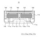
도 2 및 도 3을 참조하면, 본 발명의 일 실시예에 따른 면도기 카트리지(10)는 블레이드 하우징(110), 복수의 면도날(120) 및 하우징 커버(130)를 포함한다.Referring to FIGS. 2 and 3, a razor cartridge (10) according to one embodiment of the present invention includes a blade housing (110), a plurality of razor blades (120), and a housing cover (130).
블레이드 하우징(110)은 각 면도날(120)을 종방향으로 수용한다. 각 면도날(120)은 횡방향으로 일렬로 배열될 수 있다. 도 3을 기준으로 종방향은 가로 방향을 의미하고, 횡방향은 세로 방향을 의미한다. 도 2 및 도 3에는 면도기 카트리지(10)에 6개의 면도날(120)이 포함되는 예를 도시하였으나, 면도날(120)의 개수는 실시예에 따라 달라질 수 있다.The blade housing (110) accommodates each razor blade (120) longitudinally. Each razor blade (120) may be arranged in a row transversely. With reference to FIG. 3, the longitudinal direction means the horizontal direction, and the transverse direction means the vertical direction. FIGS. 2 and 3 illustrate an example in which a razor cartridge (10) includes six razor blades (120), but the number of razor blades (120) may vary depending on the embodiment.
이하에서 설명하는 블레이드 하우징(110)의 상면은 면도 과정에서 사용자의 피부와 접하거나 사용자의 피부와 마주하는 면이다. 블레이드 하우징(110)의 하면은 상면의 반대측에 위치하는 면으로서, 도 3에는 블레이드 하우징(110)의 하면이 도시되어 있다.The upper surface of the blade housing (110) described below is the surface that comes into contact with or faces the user's skin during the shaving process. The lower surface of the blade housing (110) is the surface located on the opposite side of the upper surface, and the lower surface of the blade housing (110) is illustrated in FIG. 3.
블레이드 하우징(110)의 전방은 면도 과정에서 사용자의 피부에 대해 블레이드 하우징(110)이 진행하는 방향(면도 방향(shaving direction))일 수 있다. 예를 들어, 블레이드 하우징(110)의 전방은 도 3을 기준으로 하방을 의미한다.The front of the blade housing (110) may be the direction in which the blade housing (110) moves relative to the user's skin during the shaving process (shaving direction). For example, the front of the blade housing (110) means downward with reference to FIG. 3.
블레이드 하우징(110)의 후방은 전술한 전방의 반대 방향으로서, 도 3을 기준으로 상방을 의미한다.The rear of the blade housing (110) is in the opposite direction to the front as described above, and means upward with reference to FIG. 3.
도 3을 참조하면, 면도기 카트리지(10)는 블레이드 하우징(110)의 하면에 인접하게 구비되는 커넥터(111)를 포함할 수 있다.Referring to FIG. 3, the razor cartridge (10) may include a connector (111) provided adjacent to the lower surface of the blade housing (110).
커넥터(111)는 면도기 핸들(40)과 탈착 가능하게 결합되는 구성이다. 커넥터(111)는 블레이드 하우징(110)의 하면에 결합되거나 블레이드 하우징(110)과 일체로 형성될 수 있다. 또는, 커넥터(111)는 후술하는 하우징 커버(130)의 하면에 결합되거나 하우징 커버(130)와 일체로 형성될 수 있다. 또는, 커넥터(111)는 일부가 블레이드 하우징(110)에 구비되고, 다른 일부가 하우징 커버(130)에 구비될 수 있다. 이하에서는 설명의 편의를 위해 커넥터(111)가 블레이드 하우징(110)의 하면에 구비되는 예를 기준으로 설명한다.The connector (111) is configured to be detachably coupled with the razor handle (40). The connector (111) may be coupled to the lower surface of the blade housing (110) or may be formed integrally with the blade housing (110). Alternatively, the connector (111) may be coupled to the lower surface of the housing cover (130) described below or may be formed integrally with the housing cover (130). Alternatively, the connector (111) may be provided in part to the blade housing (110) and in part to the housing cover (130). For convenience of explanation, the following description will be based on an example in which the connector (111) is provided in the lower surface of the blade housing (110).
커넥터(111)는 한 쌍의 커넥팅 포스트(111a), 한 쌍의 안내면(111b) 및 커넥팅 홈(111c)을 포함할 수 있다.The connector (111) may include a pair of connecting posts (111a), a pair of guide surfaces (111b) and a connecting groove (111c).
한 쌍의 커넥팅 포스트(111a)는 종방향으로 상호 이격된 상태로 블레이드 하우징(110)으로부터 돌출 형성될 수 있다. 한 쌍의 커넥팅 포스트(111a) 사이의 공간은 후술하는 면도기 핸들(40)의 커넥팅 부재가 진입하는 공간을 형성한다. 커넥팅 부재는 커넥터(111)와 탈착 가능하게 결합되는 부재이다.A pair of connecting posts (111a) may be formed to protrude from the blade housing (110) while being longitudinally spaced apart from each other. The space between the pair of connecting posts (111a) forms a space into which a connecting member of a razor handle (40) described later enters. The connecting member is a member that is detachably connected to the connector (111).
한 쌍의 안내면(111b)은 커넥팅 홈(111c)과 한 쌍의 커넥팅 포스트(111a) 사이에 구비되어, 면도기 핸들(40)의 커넥팅 부재가 커넥팅 홈(111c)으로 진입할 수 있도록 유도한다. 이를 위해, 한 쌍의 안내면(111b)은 한 쌍의 커넥팅 포스트(111a)로부터 커넥팅 홈(111c)을 향해 하향 경사면을 포함할 수 있다.A pair of guide surfaces (111b) are provided between the connecting groove (111c) and the pair of connecting posts (111a) to guide the connecting member of the razor handle (40) to enter the connecting groove (111c). To this end, the pair of guide surfaces (111b) may include a downwardly inclined surface from the pair of connecting posts (111a) toward the connecting groove (111c).
커넥팅 홈(111c)은 면도기 핸들(40)의 커넥팅 부재를 수용하며 커넥팅 부재와 탈착 가능하게 결합된다. 예를 들어, 커넥팅 홈(111c)은 커넥팅 부재와 탈착 가능한 후크 결합이 가능하게 구성될 수 있다. 도 3을 참조하면, 면도기 핸들(40)의 커넥팅 부재가 면도기 카트리지(10)의 하방에서 커넥팅 홈(111c)을 향해 진입할 수 있도록, 커넥팅 홈(111c)의 적어도 일부는 블레이드 하우징(110)의 하방으로 개방될 수 있다. 도 2를 참조하면, 면도기 카트리지(10)는 상면으로 커넥팅 홈(111c)이 노출되지 않도록 구성될 수 있다. 이를 위해, 커넥팅 홈(111c)의 상부는 블레이드 하우징(110), 탄성체 가드(150) 및 하우징 커버(130) 중 적어도 하나에 의해 가로막히도록 구성될 수 있다.The connecting groove (111c) accommodates a connecting member of the razor handle (40) and is detachably coupled with the connecting member. For example, the connecting groove (111c) may be configured to enable a detachable hook-type coupling with the connecting member. Referring to FIG. 3, at least a portion of the connecting groove (111c) may be opened downwardly toward the blade housing (110) so that the connecting member of the razor handle (40) may enter the connecting groove (111c) from the lower portion of the razor cartridge (10). Referring to FIG. 2, the razor cartridge (10) may be configured so that the connecting groove (111c) is not exposed to the upper surface. To this end, the upper portion of the connecting groove (111c) may be configured to be blocked by at least one of the blade housing (110), the elastic guard (150), and the housing cover (130).
도 3을 참조하면, 본 발명의 일 실시예에 따른 면도기 카트리지(10)는 한 쌍의 커넥팅 포스트(111a) 사이에 인디케이터(152)가 표시될 수 있다.Referring to FIG. 3, a razor cartridge (10) according to one embodiment of the present invention may have an indicator (152) displayed between a pair of connecting posts (111a).
한 쌍의 커넥팅 포스트(111a)와 인디케이터(152)는 종방향으로 동일선 상에 배치될 수 있으며, 인디케이터(152)는 커넥팅 홈(111c) 내에 표시될 수 있다.A pair of connecting posts (111a) and an indicator (152) can be arranged on the same line in the longitudinal direction, and the indicator (152) can be displayed within a connecting groove (111c).
커넥팅 홈(111c)의 양단에는 한 쌍의 안내면(111b)의 내측으로 연장되는 커넥팅 부재 수용홈(111d, 도 4 참고)을 포함할 수 있다. 커넥팅 부재 수용홈(111d)은 커넥팅 부재의 적어도 일부가 수용되는 공간이다. 인디케이터(152)와 커넥팅 부재 수용홈(111d)은 종방향으로 동일선 상에 배치될 수 있다.The connecting groove (111c) may include a connecting member receiving groove (111d, see Fig. 4) extending inwardly from a pair of guide surfaces (111b) at both ends. The connecting member receiving groove (111d) is a space in which at least a portion of the connecting member is received. The indicator (152) and the connecting member receiving groove (111d) may be arranged on the same line in the longitudinal direction.
도 3을 참조하면, 인디케이터(152)는 블레이드 하우징(110)과 하우징 커버(130) 사이에 배치될 수 있다.Referring to FIG. 3, the indicator (152) can be placed between the blade housing (110) and the housing cover (130).
또한, 인디케이터(152)는 면도날(120)과 블레이드 하우징(110)의 전방 단부(예를 들어, 제1 가드 지지부(116, 도 4 참고)의 전방 단부) 사이에 구비될 수 있다. 인디케이터(152)는 블레이드 하우징(110)의 전방 단부보다 최전방의 면도날(120)에 더 인접하도록 구비될 수 있다.Additionally, the indicator (152) may be provided between the blade (120) and the front end of the blade housing (110) (e.g., the front end of the first guard support member (116, see FIG. 4)). The indicator (152) may be provided closer to the frontmost blade (120) than to the front end of the blade housing (110).
인디케이터(152)는 면도기 핸들(40)의 장착 관련 정보를 제공할 수 있다. 장착 관련 정보는 커넥터(111)에 대한 면도기 핸들(40)의 진입 위치와 관련된 정보, 커넥터(111)에 대한 면도기 핸들(40)의 진입 방향과 관련된 정보, 커넥터(111)에 대한 면도기 핸들(40)의 장착 상태와 관련된 정보 등을 포함할 수 있다.The indicator (152) can provide information related to the mounting of the razor handle (40). The mounting information can include information related to the entry position of the razor handle (40) with respect to the connector (111), information related to the entry direction of the razor handle (40) with respect to the connector (111), information related to the mounting status of the razor handle (40) with respect to the connector (111), etc.
즉, 사용자는 인디케이터(152)의 위치를 커넥터(111)와 결합하기 위해 면도기 핸들(40)의 커넥팅 부재가 진입해야 할 진입 위치로 인식할 수 있다. 이를 위해 인디케이터(152)는 커넥터(111) 또는 블레이드 하우징(110)과 다른 색상으로 형성될 수 있다.That is, the user can recognize the position of the indicator (152) as the entry position into which the connecting member of the razor handle (40) must enter to be coupled with the connector (111). For this purpose, the indicator (152) may be formed in a different color from the connector (111) or the blade housing (110).
또한, 사용자는 인디케이터(152)에 의해 표시되는 방향을 커넥터(111)와 결합하기 위해 면도기 핸들(40)의 커넥팅 부재가 진입해야 하는 방향으로 인식할 수 있다. 이를 위해 인디케이터(152)는 면도기 핸들(40)의 커넥팅 부재가 진입하는 방향을 따라 종방향 폭이 점진적으로 작아지도록 표시될 수 있다.Additionally, the user can recognize the direction indicated by the indicator (152) as the direction in which the connecting member of the razor handle (40) must enter in order to be coupled with the connector (111). To this end, the indicator (152) can be displayed so that the longitudinal width gradually decreases along the direction in which the connecting member of the razor handle (40) enters.
인디케이터(152)가 제공하는 장착 관련 정보는 커넥터(111)와 결합 가능한 커넥팅 부재의 타입을 포함할 수도 있다. 면도기 카트리지와 면도기 핸들은 동일 제조사의 제품이라고 하더라도 모델에 따라 서로 결합이 가능하지 않은 경우가 있다. 인디케이터(152)는 커넥터(111)의 결합 구조에 따라 서로 다른 색상 및/또는 형상으로 표시되어, 사용자(152)가 인디케이터(152)를 통해 해당 면도기 카트리지(10)와 결합 가능한 면도기 핸들(40)을 쉽게 파악할 수 있도록 할 수 있다. 예를 들어, 특정 제조사에서 제조하는 면도기 카트리지(10)가 3가지 타입의 커넥터(111)로 구분되는 경우, 각 면도기 카트리지(10)는 커넥터(111)의 타입에 따라 3가지 색상 및/또는 형상 중 어느 하나의 인디케이터(152)를 포함할 수 있다. 제조사는 추후 새롭게 개발된 커넥터(111)가 적용되는 면도기 카트리지(10)에 대해서도 새로운 색상 및/또는 형상의 인디케이터(152)를 적용할 수 있다.The mounting-related information provided by the indicator (152) may include the type of a connecting member that can be combined with the connector (111). Even if a razor cartridge and a razor handle are products of the same manufacturer, they may not be combined with each other depending on the model. The indicator (152) may be displayed in different colors and/or shapes depending on the combination structure of the connector (111), so that the user (152) can easily identify the razor handle (40) that can be combined with the corresponding razor cartridge (10) through the indicator (152). For example, if razor cartridges (10) manufactured by a specific manufacturer are classified into three types of connectors (111), each razor cartridge (10) may include an indicator (152) of any one of the three colors and/or shapes depending on the type of connector (111). The manufacturer may also apply new color and/or shape indicators (152) to razor cartridges (10) to which newly developed connectors (111) are applied in the future.
또한, 면도기 핸들 역시 커넥터(111)에 결합되는 커넥팅 부재의 타입에 따라 색상으로 구별될 수 있다. 예를 들어, 면도기 핸들은 커넥팅 부재의 타입에 따라 다른 색상의 손잡이를 포함하거나, 커넥팅 부재의 적어도 일부가 다른 색상으로 제작될 수 있다. 사용자는 면도기 핸들의 색상과 인디케이터(152)의 색상이 동일한 면도기 카트리지(10)를 결합 가능한 것으로 쉽게 인식할 수 있다. 따라서, 사용자는 보유하고 있는 면도기 핸들에 결합 가능한 면도기 카트리지(10)를 색상으로 쉽게 구별할 수 있으며, 반대로 보유하고 있는 면도기 카트리지(10)에 결합 가능한 면도기 핸들도 쉽게 구별할 수 있다.In addition, the razor handle may also be distinguished by color according to the type of the connecting member coupled to the connector (111). For example, the razor handle may include a handle of a different color according to the type of the connecting member, or at least a portion of the connecting member may be manufactured in a different color. The user can easily recognize that the razor cartridge (10) having the same color as the indicator (152) of the razor handle is combinable. Accordingly, the user can easily distinguish the razor cartridge (10) combinable to the razor handle he or she is holding by color, and conversely, the user can also easily distinguish the razor handle combinable to the razor cartridge (10) he or she is holding.
또한, 커넥터(111)에 면도기 핸들(40)의 커넥팅 부재가 정상적으로 결합된 상태에서, 인디케이터(152)는 커넥팅 부재에 의해 완전히 가려지도록 배치될 수 있다. 따라서, 사용자는 면도기 핸들(40)이 면도기 카트리지(10)에 결합된 상태에서 인디케이터(152)의 적어도 일부가 보이는지 여부를 기준으로 커넥터(111)에 대한 면도기 핸들(40)의 장착 상태를 파악할 수 있다. 즉, 인디케이터(152)가 보이지 않는다면 면도기 핸들(40)이 면도기 카트리지(10)에 올바르게 결합된 상태이고, 인디케이터(152)의 적어도 일부가 보인다면 면도기 핸들(40)이 면도기 카트리지(10)에 제대로 결합되지 않은 상태임을 쉽게 인지할 수 있다.In addition, when the connecting member of the razor handle (40) is normally connected to the connector (111), the indicator (152) can be positioned to be completely covered by the connecting member. Accordingly, the user can determine the mounting status of the razor handle (40) with respect to the connector (111) based on whether at least a part of the indicator (152) is visible when the razor handle (40) is connected to the razor cartridge (10). That is, if the indicator (152) is not visible, it is easy to recognize that the razor handle (40) is properly connected to the razor cartridge (10), and if at least a part of the indicator (152) is visible, it is easy to recognize that the razor handle (40) is not properly connected to the razor cartridge (10).
도 3에 도시된 바와 같이, 커넥터(111)는 복수의 면도날(120)과 중첩되지 않도록 배치될 수 있다. 이러한 배치 관계는 복수의 면도날(120)들 사이의 공간으로 면도 잔여물(예를 들어, 면도 크림, 커팅된 체모 등)이 세척수와 함께 효과적으로 배출될 수 있도록 한다.As shown in FIG. 3, the connector (111) may be positioned so as not to overlap with the plurality of razor blades (120). This arrangement relationship allows shaving residue (e.g., shaving cream, cut hair, etc.) to be effectively discharged together with the washing water into the space between the plurality of razor blades (120).
면도날(120)은 단부에 예리한 커팅 에지(미부호)가 형성된다. 도 2를 참조하면, 면도날(120)은 커팅 에지가 블레이드 하우징(110)의 상부로 노출되도록 블레이드 하우징(110)에 안착 또는 지지된다. 또한 면도날(120)은 커팅 에지가 블레이드 하우징(110)의 전방을 향하도록 블레이드 하우징(110)에 안착 또는 지지된다.The razor blade (120) has a sharp cutting edge (not shown) formed at the end. Referring to FIG. 2, the razor blade (120) is mounted or supported on the blade housing (110) so that the cutting edge is exposed to the upper portion of the blade housing (110). In addition, the razor blade (120) is mounted or supported on the blade housing (110) so that the cutting edge faces the front of the blade housing (110).
하우징 커버(130)는 블레이드 하우징(110)과 연결되며, 면도날(120)의 전방에 형성되는 가드 영역을 확장한다. 가드 영역은 면도날(120)의 전방에 위치하여 면도 과정에서 면도날(120)보다 먼저 피부와 접촉하며 피부를 지지하거나 당겨주는 기능을 수행할 수 있다.The housing cover (130) is connected to the blade housing (110) and expands the guard area formed in front of the razor blade (120). The guard area is located in front of the razor blade (120) and can perform the function of supporting or pulling the skin by coming into contact with the skin before the razor blade (120) during the shaving process.
이하에서는, 분해사시도를 참조하여, 본 발명의 일 실시예에 따른 면도기 카트리지(10)의 구성들에 대해 보다 구체적으로 설명한다Below, with reference to the exploded perspective view, the configurations of the razor cartridge (10) according to one embodiment of the present invention will be described in more detail.
도 4는 본 발명의 일 실시예에 따른 면도기 카트리지의 분해사시도이고, 도 5는 본 발명의 일 실시예에 따른 면도기 카트리지의 탄성체 가드의 하면을 도시한 사시도이고, 도 6은 본 발명의 일 실시예에 따른 면도기 카트리지의 단면을 도시한 사시도이고, 도 7은 본 발명의 일 실시예에 따른 면도기 카트리지의 단면도이다.FIG. 4 is an exploded perspective view of a razor cartridge according to one embodiment of the present invention, FIG. 5 is a perspective view illustrating a lower surface of an elastic guard of a razor cartridge according to one embodiment of the present invention, FIG. 6 is a perspective view illustrating a cross-section of a razor cartridge according to one embodiment of the present invention, and FIG. 7 is a cross-sectional view of a razor cartridge according to one embodiment of the present invention.
도 4 및 도 6을 참조하면, 상술한 바와 같이, 본 발명의 일 실시예에 따른 면도기 카트리지(10)는 블레이드 하우징(110), 복수의 면도날(120) 및 하우징 커버(130)를 포함하며, 윤활 밴드(140), 탄성체 가드(150), 클립(160), 트리밍 블레이드(170) 및 트리머 지지체(180) 중 적어도 일부를 더 포함할 수 있다.Referring to FIGS. 4 and 6, as described above, a razor cartridge (10) according to one embodiment of the present invention includes a blade housing (110), a plurality of razor blades (120), and a housing cover (130), and may further include at least some of a lubricating band (140), an elastic guard (150), a clip (160), a trimming blade (170), and a trimmer support (180).
도 4를 참조하면, 블레이드 하우징(110)은 면도날(120)의 후방에 배치되는 후방부(113), 면도날(120)의 양측에 각각 배치되는 측방부(114) 및 면도날(120)의 전방에 배치되는 전방부(115)를 포함한다.Referring to FIG. 4, the blade housing (110) includes a rear portion (113) positioned at the rear of the blade (120), side portions (114) positioned on each side of the blade (120), and a front portion (115) positioned at the front of the blade (120).
양측의 측방부(114)에는 면도날(120)의 양측을 지지 및 수용하는 제1 면도날 지지부(112a)가 구비될 수 있다. 양측의 제1 면도날 지지부(112a)의 사이에는 면도날(120)의 중앙부를 지지 및 수용하는 제2 면도날 지지부(112b)가 구비될 수 있다. 제2 면도날 지지부(112b)는 전방부(115)와 후방부(113)를 연결하도록 구성될 수 있다. 제1 면도날 지지부(112a) 및/또는 제2 면도날 지지부(112b)는 면도날(120)을 탄성 지지하도록 구성될 수 있다.The side portions (114) on both sides may be provided with first blade support portions (112a) that support and receive both sides of the blade (120). Between the first blade support portions (112a) on both sides, a second blade support portion (112b) that supports and receives the central portion of the blade (120) may be provided. The second blade support portion (112b) may be configured to connect the front portion (115) and the rear portion (113). The first blade support portion (112a) and/or the second blade support portion (112b) may be configured to elastically support the blade (120).
제1 면도날 지지부(112a)와 제2 면도날 지지부(112b) 사이는 상하 방향으로 관통되도록 형성될 수 있다. 제1 면도날 지지부(112a)와 제2 면도날 지지부(112b) 사이의 공간은 면도 잔여물이 배출되는 린싱 공간으로 사용될 수 있다.The space between the first razor blade support (112a) and the second razor blade support (112b) can be formed to penetrate in the vertical direction. The space between the first razor blade support (112a) and the second razor blade support (112b) can be used as a rinsing space where shaving residue is discharged.
측방부(114)에는 클립(160)이 수용되는 클립홈(114a)이 형성될 수 있다. 클립(160)은 면도날(120)의 양측의 상부에 위치하여 면도날(120)이 상방으로 이탈되는 것을 방지한다. 클립홈(114a)은 제1 면도날 지지부(112a)와 횡방향으로 동일선 상에 위치하도록 형성될 수 있다.A clip groove (114a) for receiving a clip (160) may be formed in the side portion (114). The clip (160) is positioned at the upper portion of both sides of the razor blade (120) to prevent the razor blade (120) from being separated upward. The clip groove (114a) may be formed to be positioned on the same line in the transverse direction as the first razor blade support portion (112a).
도 4 및 도 6을 참조하면, 측방부(114)에는 블레이드 하우징(110)의 외측 방향으로 개방되도록 함몰 형성된 제1 배출홀(114b)이 형성될 수 있다. 제1 배출홀(114b)은 면도 과정 및/또는 세척 과정에서 면도날(120)들 사이에 존재하는 면도 잔여물이 측방으로 배출되게 한다.Referring to FIGS. 4 and 6, a first discharge hole (114b) may be formed in the side portion (114) so as to be opened in the outward direction of the blade housing (110). The first discharge hole (114b) allows shaving residue existing between the razor blades (120) to be discharged laterally during the shaving process and/or the washing process.
후방부(113)는 양측의 측방부(114)를 연결하도록 형성될 수 있으며, 후방부(113)의 상부에는 윤활 밴드(140)가 수용되는 윤활 밴드 수용홈(113a)이 형성될 수 있다. 윤활 밴드(140)는 상부면이 블레이드 하우징(110)의 상면으로 노출되도록 설치될 수 있다. 윤활 밴드(140)는 윤활 물질을 포함하며, 면도 과정에서 면도날(120)이 지나간 피부 표면에 윤활 물질이 도포 되도록 한다. 윤활 물질은 면도 후의 피부를 보호하기 위한 성분들을 포함할 수 있다.The rear portion (113) may be formed to connect the side portions (114) on both sides, and a lubrication band receiving groove (113a) for receiving a lubrication band (140) may be formed on the upper portion of the rear portion (113). The lubrication band (140) may be installed so that its upper surface is exposed to the upper surface of the blade housing (110). The lubrication band (140) includes a lubricating material and allows the lubricating material to be applied to the skin surface that the razor blade (120) passes through during the shaving process. The lubricating material may include ingredients for protecting the skin after shaving.
도 6을 참조하면, 후방부(113)의 하면에는 트리밍 블레이드(170) 및 트리머 지지체(180)를 수용하는 트리머 수용홈(미부호)이 형성될 수 있다.Referring to FIG. 6, a trimmer receiving groove (not shown) that receives a trimming blade (170) and a trimmer support (180) may be formed on the lower surface of the rear portion (113).
도 6 및 도 7을 참조하면, 트리머 지지체(180)는 트리밍 블레이드(170)가 트리머 지지체(180)와 후방부(113)의 하면 사이에 위치하도록 후방부(113)에 결합된다. 트리머 지지체(180)의 하면에는 윤활 물질이 도포될 수 있다.Referring to FIGS. 6 and 7, the trimmer support (180) is coupled to the rear portion (113) such that the trimming blade (170) is positioned between the trimmer support (180) and the lower surface of the rear portion (113). A lubricating material may be applied to the lower surface of the trimmer support (180).
트리밍 블레이드(170)는 커팅 에지가 형성된 면도날로서, 커팅 에지가 블레이드 하우징(110)의 하부로 노출되도록 트리머 수용홈 내에 수용된다.The trimming blade (170) is a razor blade with a cutting edge formed therein and is accommodated in the trimmer receiving groove so that the cutting edge is exposed to the lower portion of the blade housing (110).
전방부(115)는 양측의 측방부(114)를 연결하도록 형성될 수 있으며, 전방부(115)의 상면에는 면도날(120)의 전방에 배치되는 가드바(115a)가 형성될 수 있다.The front part (115) can be formed to connect the side parts (114) on both sides, and a guard bar (115a) that is arranged in front of the razor blade (120) can be formed on the upper surface of the front part (115).
가드바(115a)는 최전방에 위치하는 면도날(120)과 탄성체 가드(150) 사이에 위치한다. 가드바(115a)는 면도 과정에서 피부를 지지하여 최전방에 위치하는 면도날(120)에 의해 피부가 베이는 것을 방지할 수 있다.The guard bar (115a) is located between the razor blade (120) located at the front and the elastic guard (150). The guard bar (115a) can support the skin during the shaving process and prevent the skin from being cut by the razor blade (120) located at the front.
도 7을 참조하면, 가드바(115a)의 상면과 윤활 밴드(140)의 상면을 연결하는 평면은 면도 평면(S)으로 정의될 수 있다. 또는, 면도 평면(S)은 가드바(115a)의 상면과 후방부(113)의 상면의 일부를 연결하는 평면으로 정의될 수도 있다. 면도날(120)의 커팅 에지는 면도 평면(S)에 인접하여 위치할 수 있으며, 적어도 일부의 면도날(120)은 면도 평면(S)보다 하부에 위치하거나, 면도 평면(S)보다 상부에 위치할 수 있다. 예를 들어, 면도날(120)들 중 전방에 위치하는 면도날들은 피부 베임을 방지하기 위해 커팅 에지가 면도 평면(S)보다 하부에 위치하는 음의 돌출값을 갖도록 배치되고, 면도날(120)들 중 후방에 위치하는 면도날들은 보다 깨끗한 면도를 위해 커팅 에지가 면도 평면(S)보다 상부에 위치하는 양의 돌출값을 갖도록 배치되며, 면도날(120)들 중 중앙에 위치하는 면도날들은 커팅 에지가 면도 평면(S)에 위치하는 0의 돌출값을 갖도록 배치될 수 있다.Referring to FIG. 7, a plane connecting the upper surface of the guard bar (115a) and the upper surface of the lubricating band (140) may be defined as a shaving plane (S). Alternatively, the shaving plane (S) may be defined as a plane connecting the upper surface of the guard bar (115a) and a portion of the upper surface of the rear portion (113). The cutting edge of the razor blade (120) may be positioned adjacent to the shaving plane (S), and at least a portion of the razor blade (120) may be positioned below the shaving plane (S) or above the shaving plane (S). For example, among the blades (120), the blades positioned at the front may be positioned so that their cutting edges have a negative protrusion value positioned lower than the shaving plane (S) to prevent skin cuts, the blades positioned at the rear may be positioned so that their cutting edges have a positive protrusion value positioned higher than the shaving plane (S) to ensure a cleaner shave, and the blades positioned at the center of the blades (120) may be positioned so that their cutting edges have a protrusion value of 0 positioned on the shaving plane (S).
도 4를 참조하면, 블레이드 하우징(110)은 전방부(115)로부터 전방을 향해 연장되는 제1 가드 지지부(116)를 더 포함할 수 있다.Referring to FIG. 4, the blade housing (110) may further include a first guard support member (116) extending forward from the front portion (115).
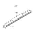
제1 가드 지지부(116)는 탄성체 가드(150)를 지지한다. 탄성체 가드(150)는 면도 과정에서 사용자의 피부에 밀착되어 피부를 당겨 면도날(120)에 의한 면도 효과를 향상시킨다. 탄성체 가드(150)가 사용자의 피부를 보다 효과적으로 당길 수 있도록, 탄성체 가드(150)의 상면에는 양각 또는 음각으로 형성되는 패턴이 형성될 수 있으며, 탄성체 가드(150)의 상면은 고무 또는 실리콘 등의 재질로 형성될 수 있다.The first guard support member (116) supports the elastic guard (150). The elastic guard (150) adheres closely to the user's skin during the shaving process and pulls the skin to improve the shaving effect by the razor blade (120). In order for the elastic guard (150) to pull the user's skin more effectively, a pattern formed in a positive or negative shape may be formed on the upper surface of the elastic guard (150), and the upper surface of the elastic guard (150) may be formed of a material such as rubber or silicone.
도 4를 참조하면, 제1 가드 지지부(116)에는 상하로 관통된 관통 슬릿(117)이 형성될 수 있다. 도 5를 참조하면, 탄성체 가드(150)는 제1 가드 지지부(116)에 안착되어 상면이 블레이드 하우징(110)의 상부를 통해 노출되는 가드 본체(151)와, 관통 슬릿(117)에 삽입되도록 가드 본체(151)로부터 하방으로 돌출 형성되는 인디케이터(152)를 포함할 수 있다. 도 6 및 도 7을 참조하면, 인디케이터(152)는 관통 슬릿(117) 내에 삽입되어 블레이드 하우징(110)의 하면을 통해 노출될 수 있다. 실시예에 따라, 인디케이터(152)는 가드 본체(151)로부터 하방으로 돌출 형성되지 않을 수 있으며, 관통 슬릿(117)을 통해 시각적으로 확인 가능한 가드 본체(151)의 일부를 의미할 수 있다.Referring to FIG. 4, a through slit (117) extending vertically may be formed in the first guard support member (116). Referring to FIG. 5, the elastic guard (150) may include a guard body (151) that is mounted on the first guard support member (116) and has an upper surface exposed through the upper portion of the blade housing (110), and an indicator (152) that protrudes downward from the guard body (151) to be inserted into the through slit (117). Referring to FIGS. 6 and 7, the indicator (152) may be inserted into the through slit (117) and exposed through the lower surface of the blade housing (110). Depending on the embodiment, the indicator (152) may not protrude downward from the guard body (151) and may mean a part of the guard body (151) that is visually confirmed through the through slit (117).
도 3을 참조하면, 관통 슬릿(117)은 커넥팅 홈(111c) 내에 위치하도록 형성될 수 있다. 관통 슬릿(117)을 통해 블레이드 하우징(110)의 하면으로 노출되는 인디케이터(152)는 커넥팅 홈(111c) 내에서 면도기 핸들(40)의 장착 관련 정보를 제공한다. 면도기 핸들(40)의 결합 방향이 시각적으로 인지되도록, 관통 슬릿(117)은 종방향 폭이 면도기 핸들(40)의 진입 방향을 따라 점진적으로 작아지도록 형성될 수 있다.Referring to FIG. 3, the through slit (117) may be formed to be located within the connecting groove (111c). An indicator (152) exposed to the lower surface of the blade housing (110) through the through slit (117) provides information related to the mounting of the razor handle (40) within the connecting groove (111c). In order for the engaging direction of the razor handle (40) to be visually recognized, the through slit (117) may be formed to have a longitudinal width that gradually decreases along the entry direction of the razor handle (40).
관통 슬릿(117)을 통해 노출되는 인디케이터(152)를 사용자가 시각적으로 쉽게 인지하도록, 탄성체 가드(150)와 블레이드 하우징(110)은 서로 다른 색상으로 형성될 수 있다. 탄성체 가드(150)는 블레이드 하우징(110)과 다른 재질, 예를 들어 고무 또는 실리콘으로 형성되므로, 탄성체 가드(150)를 블레이드 하우징(110)과 다른 색상으로 제작하는 것은 어렵지 않다. 따라서, 본 실시예에 따른 면도기 카트리지(10)와 같이, 인디케이터(152)를 탄성체 가드(150)에 포함시키는 것이 바람직하다.In order for the user to easily visually recognize the indicator (152) exposed through the through slit (117), the elastic guard (150) and the blade housing (110) may be formed in different colors. Since the elastic guard (150) is formed of a different material from the blade housing (110), for example, rubber or silicone, it is not difficult to manufacture the elastic guard (150) in a different color from the blade housing (110). Therefore, it is preferable to include the indicator (152) in the elastic guard (150), as in the razor cartridge (10) according to the present embodiment.
도 4에는 관통 슬릿(117)이 블레이드 하우징(110)의 전방을 향해 개방된 형상으로 도시되었으나, 관통 슬릿(117)은 블레이드 하우징(110)의 전방 영역에서 제1 가드 지지부(116)에 의해 둘러싸이도록 형성될 수도 있다.In FIG. 4, the through slit (117) is illustrated as being open toward the front of the blade housing (110), but the through slit (117) may also be formed to be surrounded by the first guard support member (116) in the front region of the blade housing (110).
도 3 및 도 4를 참조하면, 전방부(115)의 하면에는 전술한 한 쌍의 커넥팅 포스트(111a), 한 쌍의 안내면(111b) 및 커넥팅 홈(111c)이 구비될 수 있다.Referring to FIGS. 3 and 4, the lower surface of the front portion (115) may be provided with a pair of connecting posts (111a), a pair of guide surfaces (111b), and a connecting groove (111c) as described above.
하우징 커버(130)는 면도날(120)의 커팅 에지의 적어도 일부가 노출되는 면도날 윈도우(131)와, 면도날 윈도우(131)의 적어도 일부를 둘러싸도록 형성되는 윈도우 프레임(132)을 포함한다.The housing cover (130) includes a blade window (131) in which at least a portion of the cutting edge of the blade (120) is exposed, and a window frame (132) formed to surround at least a portion of the blade window (131).
도 4를 참조하면, 윈도우 프레임(132)은 면도날(120)의 전방에 배치되는 전방 프레임(133)과 면도날(120)의 양측에 각각 배치되는 측방 프레임(134)을 포함할 수 있다.Referring to FIG. 4, the window frame (132) may include a front frame (133) positioned in front of the blade (120) and side frames (134) positioned on each side of the blade (120).
측방 프레임(134)은 전방 프레임(133)의 양측으로부터 후방을 향해 연장되며, 블레이드 하우징(110)의 측방부(114)의 외측에 결합될 수 있다. 도 4 및 도 6을 참조하면, 측방 프레임(134)에는 제1 배출홀(114b)과 연통하는 제2 배출홀(134a)이 형성될 수 있다. 하우징 커버(130)가 블레이드 하우징(110)에 결합된 상태에서 제2 배출홀(134a)은 제1 배출홀(114b)과 종방향으로 나란하게 배치될 수 있다. 제1 배출홀(114b) 및 제2 배출홀(134a)은 면도 잔여물의 측방 배출 및 세척수의 측방 유입을 가능하게 하여, 면도날(120)들 사이에 존재하는 면도 잔여물의 배출 및 세척 효과를 향상시킨다.The side frame (134) extends rearwardly from both sides of the front frame (133) and can be coupled to the outer side of the side portion (114) of the blade housing (110). Referring to FIGS. 4 and 6, the side frame (134) can be formed with a second discharge hole (134a) communicating with the first discharge hole (114b). In a state where the housing cover (130) is coupled to the blade housing (110), the second discharge hole (134a) can be arranged longitudinally parallel to the first discharge hole (114b). The first discharge hole (114b) and the second discharge hole (134a) enable the lateral discharge of shaving residue and the lateral introduction of washing water, thereby enhancing the discharge and washing effect of shaving residue existing between the razor blades (120).
전방 프레임(133)은 면도날(120)의 전방에 위치되는 플라스틱 가드(133a)를 포함한다.The front frame (133) includes a plastic guard (133a) positioned in front of the razor blade (120).
본 실시예에 따른 면도기 카트리지(10)는 종래의 면도기 카트리지에 비해 플라스틱 가드 영역이 새롭게 형성되었다. 면도 과정에서 피부가 플라스틱 가드 영역에서 과도하게 미끄러지는 것을 방지하기 위해, 플라스틱 가드(133a)는 상면의 적어도 일부가 불규칙한 패턴의 요철 영역으로 형성될 수 있다. 요철 영역은 종방향 표면 조도(Ra)가 100 내지 300 마이크로미터 사이의 값을 갖도록 형성될 수 있다.The razor cartridge (10) according to the present embodiment has a newly formed plastic guard area compared to conventional razor cartridges. In order to prevent the skin from excessively slipping in the plastic guard area during the shaving process, the plastic guard (133a) may have at least a portion of its upper surface formed as an irregularly patterned uneven area. The uneven area may be formed to have a longitudinal surface roughness (Ra) of between 100 and 300 micrometers.
요철 영역을 포함하는 플라스틱 가드(133a)는 면도 과정에서 면도날(120) 보다 먼저 피부를 지나치며 피부나 수염에 붙은 각질 및/또는 과도하게 도포된 쉐이빙 폼을 제거하고, 피부를 당겨 면도날(120)에 의한 면도 효과를 향상시킨다. 요철 영역은 플라스틱 가드(133a) 내에서 탄성체 가드(150)에 인접하도록 형성될 수 있다.The plastic guard (133a) including the uneven area passes over the skin before the razor blade (120) during the shaving process, removes dead skin cells and/or excessively applied shaving foam attached to the skin or beard, and pulls the skin to improve the shaving effect by the razor blade (120). The uneven area may be formed adjacent to the elastic guard (150) within the plastic guard (133a).
도 7을 참조하면, 플라스틱 가드(133a)의 상면은 면도 평면(S)보다 하부에 위치할 수 있으며, 면도날(120)의 커팅 에지, 가드바(115a) 및/또는 탄성체 가드(150)의 상면보다 하부에 위치할 수 있다.Referring to FIG. 7, the upper surface of the plastic guard (133a) may be positioned lower than the shaving plane (S), and may be positioned lower than the cutting edge of the razor blade (120), the guard bar (115a), and/or the upper surface of the elastic guard (150).
면도날(120)의 전방에 위치하는 카트리지 전방 영역에 대한 플라스틱 가드(133a)의 면적은 0.2 내지 0.9가 될 수 있다. 카트리지 전방 영역은 가드바(115a), 탄성체 가드(150) 및 전방 프레임(133)을 포함하는 개념일 수 있다.The area of the plastic guard (133a) for the front area of the cartridge located in front of the razor blade (120) can be 0.2 to 0.9. The front area of the cartridge can be a concept including a guard bar (115a), an elastic guard (150), and a front frame (133).
카트리지 전방 영역에 대한 요철 영역의 면적은 0.2 내지 0.3이 될 수 있다.The area of the uneven area on the front side of the cartridge can be 0.2 to 0.3.
도 4 등에는 관통 슬릿(117)이 블레이드 하우징(110)에 형성되는 예를 도시하였으나, 실시예에 따라, 관통 슬릿(117)은 블레이드 하우징(110) 및 윈도우 프레임(132) 중 적어도 하나에 형성될 수 있다. 즉, 관통 슬릿(117)의 적어도 일부는 플라스틱 가드(133a)를 상하로 관통하며 형성될 수도 있다. 이 경우, 관통 슬릿(117)을 통해 노출되는 인디케이터(152)는 블레이드 하우징(110)과 플라스틱 가드(133a)에 의해 둘러싸일 수 있다.Although FIG. 4 illustrates an example in which a through slit (117) is formed in the blade housing (110), depending on the embodiment, the through slit (117) may be formed in at least one of the blade housing (110) and the window frame (132). That is, at least a portion of the through slit (117) may be formed to penetrate the plastic guard (133a) upwardly and downwardly. In this case, the indicator (152) exposed through the through slit (117) may be surrounded by the blade housing (110) and the plastic guard (133a).
도 4를 참조하면, 전방 프레임(133)은 플라스틱 가드(133a)로부터 후방을 향해 연장되는 제2 가드 지지부(135)를 더 포함할 수 있다. 제2 가드 지지부(135)는 제1 가드 지지부(116)와 함께 탄성체 가드(150)를 지지할 수 있다. 도 4에 도시된 바와 같이, 제2 가드 지지부(135)는 상호 이격된 한 쌍으로 구성될 수 있으며, 한 쌍의 제2 가드 지지부(135)의 사이에 존재하는 공간은 관통 슬릿(117)과 연결되어 인디케이터(152)의 일부를 수용할 수 있다.Referring to FIG. 4, the front frame (133) may further include a second guard support (135) extending rearwardly from the plastic guard (133a). The second guard support (135) may support the elastic guard (150) together with the first guard support (116). As illustrated in FIG. 4, the second guard support (135) may be configured as a pair spaced apart from each other, and a space existing between the pair of second guard support (135) may be connected to a through slit (117) to accommodate a portion of the indicator (152).
인디케이터(152)는 관통 슬릿(117) 내에서 전후좌우가 블레이드 하우징(110)과 하우징 커버(130)에 의해 둘러싸인 상태로 지지되므로, 인디케이터(152)와 주변 지지 구조(블레이드 하우징(110)과 하우징 커버(130))의 접촉 면적이 증가되어, 인디케이터(152)가 면도기 카트리지(10) 내에 보다 견고하게 지지되며, 외부 충격 등에 의해 인디케이터(152)가 면도기 카트리지(10)로부터 이탈되는 것이 방지된다.Since the indicator (152) is supported in a state where it is surrounded by the blade housing (110) and the housing cover (130) on the front, back, left, and right sides within the through slit (117), the contact area between the indicator (152) and the surrounding support structure (the blade housing (110) and the housing cover (130)) increases, so that the indicator (152) is supported more firmly within the razor cartridge (10), and the indicator (152) is prevented from being detached from the razor cartridge (10) due to external impact, etc.
도 4 및 도 6을 참조하면, 전방 프레임(133)은 하방을 향해 연장되는 한 쌍의 보강 포스트(136)를 더 포함할 수 있다. 보강 포스트(136)는 각각 커넥팅 포스트(111a)의 외측에 결합될 수 있다.Referring to FIGS. 4 and 6, the front frame (133) may further include a pair of reinforcing posts (136) extending downward. The reinforcing posts (136) may each be coupled to the outer side of a connecting post (111a).
보강 포스트(136) 및 측방 프레임(134)은 블레이드 하우징(110)과 하우징 커버(130) 사이의 접촉 면적을 넓혀 블레이드 하우징(110)과 하우징 커버(130) 사이의 결합력을 강화할 수 있다.The reinforcing post (136) and the side frame (134) can increase the contact area between the blade housing (110) and the housing cover (130) and strengthen the bonding force between the blade housing (110) and the housing cover (130).
하우징 커버(130)의 플라스틱 가드(133a)는 광 투과성 재질로 형성될 수 있다. 즉, 플라스틱 가드(133a)는 투명 또는 반투명한 재질로 형성될 수 있다. 이 경우, 사용자는 면도 시에 플라스틱 가드(133a)를 통해 면도 부위를 시각적으로 확인할 수 있다.The plastic guard (133a) of the housing cover (130) may be formed of a light-transmitting material. That is, the plastic guard (133a) may be formed of a transparent or translucent material. In this case, the user can visually check the shaving area through the plastic guard (133a) during shaving.
면도 시에 면도기 카트리지(10)의 상면은 피부와 접촉한 상태를 유지하므로, 사용자는 거울을 통해 면도기 카트리지(10)의 하면을 확인하면서 면도를 하게 된다. 본 실시예에 따른 면도기 카트리지(10)는 플라스틱 가드(133a)가 광투과성 재질로 형성되므로, 면도 시에 사용자는 플라스틱 가드(133a)가 지지하는 피부를 시각적으로 확인하여, 현재 면도날(120)의 위치와, 이후에 면도날(120)에 의해 면도가 이루어질 피부의 위치를 정확하게 인식할 수 있다. 특히, 코 밑과 같이 좁은 영역이나 정밀한 면도가 요구되는 영역을 면도할 때에, 플라스틱 가드(133a)를 통해 면도 부위 및/또는 면도 예정 부위를 시각적으로 확인할 수 있으므로, 보다 안전하고 정확한 면도가 가능해진다.Since the upper surface of the razor cartridge (10) remains in contact with the skin during shaving, the user shaves while checking the lower surface of the razor cartridge (10) through the mirror. Since the razor cartridge (10) according to the present embodiment has a plastic guard (133a) formed of a light-transmitting material, the user can visually check the skin supported by the plastic guard (133a) during shaving, and accurately recognize the current position of the razor blade (120) and the position of the skin to be shaved by the razor blade (120) in the future. In particular, when shaving a narrow area such as under the nose or an area requiring precise shaving, the shaving area and/or the area to be shaved can be visually checked through the plastic guard (133a), thereby enabling a safer and more precise shaving.
하우징 커버(130)는 플라스틱 가드(133a)만 광 투과성 재질로 형성되거나, 전방 프레임(133)만 광 투과성 재질로 형성될 수 있다. 또는 하우징 커버(130)가 전체적으로 광 투과성 재질로 형성될 수도 있다.The housing cover (130) may be formed of a light-transmitting material only for the plastic guard (133a), or may be formed of a light-transmitting material only for the front frame (133). Alternatively, the housing cover (130) may be formed entirely of a light-transmitting material.
도 3을 참조하면, 블레이드 하우징(110)의 커넥터(111)는 불투명한 재질로 형성되고, 플라스틱 가드(133a), 전방 프레임(133) 또는 하우징 커버(130)가 광 투과성의 재질로 형성되면, 면도기 카트리지(10)의 하면에서 커넥터(111)가 보다 명확하게 시각적으로 구분될 수 있다.Referring to FIG. 3, the connector (111) of the blade housing (110) is formed of an opaque material, and when the plastic guard (133a), front frame (133) or housing cover (130) is formed of a light-transmitting material, the connector (111) can be more clearly visually distinguished from the lower surface of the razor cartridge (10).
블레이드 하우징(110)은 하우징 커버(130)와 구별되도록 불투명한 재질로 형성될 수 있으나, 실시예에 따라 블레이드 하우징(110)도 광 투과성 재질로 형성될 수 있다.The blade housing (110) may be formed of an opaque material to be distinguished from the housing cover (130), but depending on the embodiment, the blade housing (110) may also be formed of a light-transmitting material.
블레이드 하우징(110)과 하우징 커버(130)는 일체로 형성될 수 있다. 블레이드 하우징(110)과 하우징 커버(130)는 불투명한 재질로 일체로 형성되거나, 광 투과성 재질로 일체로 형성될 수 있다. 또는, 블레이드 하우징(110)은 불투명한 재질로 형성되고, 하우징 커버(130)의 적어도 일부(예를 들어, 전방 프레임(133) 또는 플라스틱 가드(133a))는 광 투과성의 재질로 형성되되, 이중 사출 등의 방법을 통해 블레이드 하우징(110)과 하우징 커버(130)가 일체로 형성될 수 있다.The blade housing (110) and the housing cover (130) may be formed integrally. The blade housing (110) and the housing cover (130) may be formed integrally of an opaque material or may be formed integrally of a light-transmitting material. Alternatively, the blade housing (110) may be formed of an opaque material, and at least a portion of the housing cover (130) (e.g., the front frame (133) or the plastic guard (133a)) may be formed of a light-transmitting material, but the blade housing (110) and the housing cover (130) may be formed integrally by a method such as double injection.
이하에서는, 본 발명의 다른 실시예에 따른 면도기 카트리지에 대해 설명한다. 설명의 편의를 위하여 일 실시예와 유사한 부분은 동일한 도면부호를 사용하고, 일 실시예와 공통되는 부분은 그 설명을 생략한다.Hereinafter, a razor cartridge according to another embodiment of the present invention will be described. For convenience of explanation, parts similar to those in one embodiment are given the same reference numerals, and parts common to those in one embodiment are omitted for description.
도 8은 본 발명의 다른 실시예에 따른 면도기 카트리지의 분해사시도이다.FIG. 8 is an exploded perspective view of a razor cartridge according to another embodiment of the present invention.
도 8을 참조하면, 본 발명의 다른 실시예에 따른 면도기 카트리지(20)는, 전술한 일 실시예에 따른 면도기 카트리지(10)에서 하우징 커버(130)로 설명한 부분이 블레이드 하우징(210)에 포함된다.Referring to FIG. 8, a razor cartridge (20) according to another embodiment of the present invention includes a part described as a housing cover (130) in the razor cartridge (10) according to the above-described embodiment in a blade housing (210).
블레이드 하우징(210)은 불투명 재질 또는 광 투과성 재질로 단일 사출될 수 있다. 탄성체 가드(150)와 같이, 블레이드 하우징(210)과 다른 재질로 형성되는 부분은 이중 사출 등의 방법으로 블레이드 하우징(210)과 일체로 제조될 수 있다.The blade housing (210) can be single-shot molded from an opaque material or a light-transmitting material. A portion formed from a different material from the blade housing (210), such as an elastic guard (150), can be manufactured integrally with the blade housing (210) by a method such as double-shot molding.
본 발명의 다른 실시예에 따른 면도기 카트리지(20)는, 관통 슬릿(117)이 블레이드 하우징(210)을 상하로 관통하여 형성되며, 관통 슬릿(117)은 블레이드 하우징(210)의 전방 영역에서 블레이드 하우징(210)에 의해 둘러싸도록 형성될 수 있다. 전술한 실시예와 유사하게, 관통 슬릿(117)은 커넥팅 홈(111c) 내에 위치하도록 형성될 수 있다.According to another embodiment of the present invention, a razor cartridge (20) is formed such that a through slit (117) penetrates the blade housing (210) vertically, and the through slit (117) may be formed to be surrounded by the blade housing (210) in a front region of the blade housing (210). Similar to the above-described embodiment, the through slit (117) may be formed to be located within the connecting groove (111c).
인디케이터(152)는 탄성체 가드(150)의 하방에 구비될 수 있으며, 관통 슬릿(117) 내에 삽입되어 커넥팅 홈(111c)을 통해 블레이드 하우징(210)의 하면으로 노출될 수 있다.The indicator (152) can be provided at the bottom of the elastic guard (150) and can be inserted into the through slit (117) and exposed to the lower surface of the blade housing (210) through the connecting groove (111c).
인디케이터(152)는 블레이드 하우징(210)에 의해 둘러싸이도록 배치될 수 있다. 이 경우, 인디케이터(152)는 주변부가 블레이드 하우징(210)에 의해 측방 지지되어 외부 충격 등에 의해 블레이드 하우징(210)로부터 이탈되는 것이 방지된다.The indicator (152) may be arranged to be surrounded by the blade housing (210). In this case, the indicator (152) is supported laterally by the blade housing (210) at its periphery, thereby preventing it from being separated from the blade housing (210) due to external impact, etc.
인디케이터(152)는 면도날(120)과 블레이드 하우징(110)의 전방 단부 사이에 구비될 수 있다. 인디케이터(152)는 블레이드 하우징(110)의 전방 단부보다 최전방의 면도날(120)에 더 인접하도록 구비될 수 있다.The indicator (152) may be provided between the blade (120) and the front end of the blade housing (110). The indicator (152) may be provided closer to the frontmost blade (120) than to the front end of the blade housing (110).
본 발명이 속하는 기술분야의 통상의 지식을 가진 자는 본 발명이 그 기술적 사상이나 필수적인 특징을 변경하지 않고서 다른 구체적인 형태로 실시될 수 있다는 것을 이해할 수 있을 것이다. 그러므로 이상에서 기술한 실시예들은 모든 면에서 예시적인 것이며 한정적이 아닌 것으로 이해해야만 한다. 본 발명의 범위는 상기 상세한 설명보다는 후술하는 특허청구범위에 의하여 나타내어지며, 특허청구범위의 의미 및 범위 그리고 그 균등 개념으로부터 도출되는 모든 변경 또는 변형된 형태가 본 발명의 범위에 포함되는 것으로 해석되어야 한다.A person having ordinary skill in the art to which the present invention pertains will understand that the present invention can be implemented in other specific forms without changing the technical idea or essential characteristics thereof. Therefore, it should be understood that the embodiments described above are exemplary in all respects and not restrictive. The scope of the present invention is indicated by the claims described below rather than the detailed description above, and all changes or modified forms derived from the meaning and scope of the claims and their equivalent concepts should be interpreted as being included in the scope of the present invention.
1: 면도기 조립체10, 20: 면도기 카트리지
40: 면도기 핸들41: 핸들 바디
42: 핸들 헤드110, 210: 블레이드 하우징
120: 면도날130: 하우징 커버
140: 윤활 밴드150: 탄성체 가드
152: 인디케이터160: 클립
170: 트리밍 블레이드180: 트리머 지지체1:
40: Razor handle 41: Handle body
42: Handle
120: Razor blade 130: Housing cover
140: Lubricating band 150: Elastic guard
152: Indicator 160: Clip
170: Trimming blade 180: Trimmer support
Claims (18)
Translated fromKorean커팅 에지가 형성된 적어도 하나의 면도날;
상기 면도날이 종방향으로 수용되는 면도날 안착부, 상기 면도날이 노출되는 상면, 및 상기 상면과 반대되는 하면을 포함하는 블레이드 하우징; 및
상기 하면에 인접하게 형성되며 상기 면도기 핸들이 진입하는 커넥팅 홈을 포함하는 커넥터;를 포함하고
상기 커넥팅 홈 내에 상기 면도기 핸들의 장착 관련 정보를 제공하는 인디케이터가 구비된, 면도기 조립체.razor handle;
At least one razor blade having a cutting edge formed thereon;
A blade housing including a blade mounting portion in which the razor blade is longitudinally received, an upper surface on which the razor blade is exposed, and a lower surface opposite to the upper surface; and
A connector formed adjacent to the above surface and including a connecting groove into which the razor handle enters;
A razor assembly having an indicator providing information related to the mounting of the razor handle within the connecting groove.
상기 장착 관련 정보는 상기 커넥터에 대한 상기 면도기 핸들의 진입 방향과 관련된 정보를 포함하는, 면도기 조립체.In the first paragraph,
A razor assembly, wherein said mounting related information includes information related to the direction of entry of said razor handle into said connector.
상기 장착 관련 정보는 상기 커넥터에 대한 상기 면도기 핸들의 진입 위치와 관련된 정보를 포함하는, 면도기 조립체.In the first paragraph,
A razor assembly, wherein said mounting related information includes information relating to an entry position of said razor handle relative to said connector.
상기 블레이드 하우징에 배치되는 탄성체 가드;를 더 포함하고,
상기 블레이드 하우징은 상기 탄성체 가드의 적어도 일부가 상기 하면에서 상기 커넥팅 홈 내에 노출되도록 형성되고,
상기 인디케이터는 상기 커넥팅 홈 내에 노출된 상기 탄성체 가드인, 면도기 조립체.In the first paragraph,
Further comprising an elastic guard disposed on the blade housing;
The above blade housing is formed such that at least a portion of the elastic guard is exposed within the connecting groove on the lower surface,
A razor assembly, wherein the above indicator is the elastic guard exposed within the above connecting groove.
상기 블레이드 하우징은 상기 탄성체 가드를 지지하는 가드 지지부를 더 포함하고,
상기 가드 지지부는 상기 커넥팅 홈 내에 상기 탄성체 가드의 적어도 일부가 노출되도록 관통 슬릿을 포함하는, 면도기 조립체.In paragraph 4,
The above blade housing further includes a guard support member that supports the elastic guard,
A razor assembly, wherein said guard support member includes a through slit to expose at least a portion of said elastic guard within said connecting groove.
상기 관통 슬릿은 상기 블레이드 하우징의 전방 영역에서 상기 블레이드 하우징에 의해 둘러싸이도록 형성되는, 면도기 조립체.In paragraph 5,
A razor assembly, wherein the through slit is formed so as to be surrounded by the blade housing in the front region of the blade housing.
상기 관통 슬릿의 종방향 폭은 상기 면도기 핸들의 진입 방향을 따라 점진적으로 작아지는, 면도기 조립체.In paragraph 5,
A razor assembly, wherein the longitudinal width of the above-described through slit gradually decreases along the entry direction of the above-described razor handle.
상기 탄성체 가드는 상기 블레이드 하우징과 다른 색상으로 형성되는, 면도기 조립체.In paragraph 4,
A razor assembly wherein the elastic guard is formed in a different color from the blade housing.
상기 커팅 에지의 적어도 일부와 상기 탄성체 가드가 노출되는 면도날 윈도우 및 상기 면도날 윈도우의 적어도 일부를 둘러싸도록 형성되며 상기 블레이드 하우징에 결합되는 윈도우 프레임을 포함하는 하우징 커버;를 더 포함하고,
상기 윈도우 프레임 및 상기 블레이드 하우징 중 적어도 하나는, 상기 탄성체 가드의 적어도 일부가 상기 커넥팅 홈 내에 노출되도록 하는 관통 슬릿이 형성되는, 면도기 조립체.In paragraph 4,
Further comprising a housing cover including a blade window exposing at least a portion of the cutting edge and the elastic guard, and a window frame formed to surround at least a portion of the blade window and coupled to the blade housing;
A razor assembly, wherein at least one of the window frame and the blade housing has a through slit formed therein such that at least a portion of the elastic guard is exposed within the connecting groove.
상기 인디케이터는 상기 블레이드 하우징과 상기 윈도우 프레임에 의해 둘러싸이는, 면도기 조립체.In Article 9,
A razor assembly, wherein the above indicator is surrounded by the blade housing and the window frame.
상기 인디케이터는 상기 면도날과 상기 블레이드 하우징의 전방 단부 사이에 구비되되, 상기 블레이드 하우징의 단부보다 상기 면도날에 더 인접하도록 구비되는, 면도기 조립체.In the first paragraph,
A razor assembly, wherein the indicator is provided between the blade and the front end of the blade housing, but is provided closer to the blade than the end of the blade housing.
상부에 상기 면도날이 종방향으로 수용되는 면도날 안착부가 형성되고, 하부에 면도기 핸들이 결합되는 커넥터가 구비되는 블레이드 하우징;을 포함하고,
상기 커넥터는 상기 면도기 핸들이 진입하는 공간의 양측에 형성되는 한 쌍의 커넥팅 포스트를 포함하고,
상기 한 쌍의 커넥팅 포스트 사이에 상기 면도기 핸들의 진입 위치를 지시하는 인디케이터가 표시된, 면도기 카트리지.At least one razor blade having a cutting edge formed thereon; and
A blade housing having a blade mounting portion formed at the upper portion for receiving the razor blade longitudinally and a connector provided at the lower portion for connecting the razor handle;
The above connector includes a pair of connecting posts formed on both sides of the space into which the razor handle enters,
A razor cartridge having an indicator indicating the entry position of the razor handle between the pair of connecting posts.
상기 한 쌍의 커넥팅 포스트와 상기 인디케이터는 종방향으로 동일선 상에 배치되는, 면도기 카트리지.In Article 12,
A razor cartridge, wherein the above pair of connecting posts and the above indicator are arranged on the same line in the longitudinal direction.
상기 블레이드 하우징의 상면에 배치되는 탄성체 가드;를 더 포함하고,
상기 블레이드 하우징은 상기 탄성체 가드의 적어도 일부가 상기 블레이드 하우징의 하면을 통해 상기 한 쌍의 커넥팅 포스트 사이로 노출되도록 형성되고,
상기 인디케이터는 상기 한 쌍의 커넥팅 포스트 사이에 노출된 상기 탄성체 가드인, 면도기 카트리지.In Article 12,
Further comprising an elastic guard disposed on the upper surface of the blade housing;
The blade housing is formed such that at least a portion of the elastic guard is exposed between the pair of connecting posts through the lower surface of the blade housing,
A razor cartridge, wherein the above indicator is the elastic guard exposed between the pair of connecting posts.
상기 블레이드 하우징은 상기 탄성체 가드를 지지하는 가드 지지부를 더 포함하고,
상기 가드 지지부는 상기 한 쌍의 커넥팅 포스트 사이에 상기 탄성체 가드의 적어도 일부가 상기 블레이드 하우징의 하면을 통해 노출되도록 하는 관통 슬릿의 적어도 일부를 포함하는, 면도기 카트리지.In Article 14,
The above blade housing further includes a guard support member that supports the elastic guard,
A razor cartridge, wherein said guard support member includes at least a portion of a through slit between said pair of connecting posts such that at least a portion of said elastic guard is exposed through the lower surface of said blade housing.
상기 관통 슬릿의 종방향 폭은 상기 면도기 핸들의 진입 방향을 따라 점진적으로 작아지는, 면도기 카트리지.In Article 15,
A razor cartridge, wherein the longitudinal width of the above-mentioned through slit gradually decreases along the entry direction of the above-mentioned razor handle.
상기 탄성체 가드는 상기 블레이드 하우징과 다른 색상으로 형성되는, 면도기 카트리지.In Article 15,
A razor cartridge wherein the elastic guard is formed in a different color from the blade housing.
상기 커팅 에지의 적어도 일부와 상기 탄성체 가드가 노출되는 면도날 윈도우 및 상기 면도날 윈도우의 적어도 일부를 둘러싸도록 형성되며 상기 블레이드 하우징에 결합되는 윈도우 프레임을 포함하는 하우징 커버;를 더 포함하고,
상기 인디케이터는 상기 블레이드 하우징과 상기 윈도우 프레임에 의해 둘러싸이는, 면도기 카트리지.In Article 15,
Further comprising a housing cover including a blade window exposing at least a portion of the cutting edge and the elastic guard, and a window frame formed to surround at least a portion of the blade window and coupled to the blade housing;
A razor cartridge, wherein the above indicator is surrounded by the blade housing and the window frame.
Priority Applications (3)
| Application Number | Priority Date | Filing Date | Title |
|---|---|---|---|
| KR1020230139771AKR20250055975A (en) | 2023-10-18 | 2023-10-18 | Razor cartridge and razor assembly including the same |
| US18/917,871US20250128442A1 (en) | 2023-10-18 | 2024-10-16 | Razor cartridge and razor assembly including the same |
| EP24207080.3AEP4541534A1 (en) | 2023-10-18 | 2024-10-17 | Razor cartridge and razor assembly including the same |
Applications Claiming Priority (1)
| Application Number | Priority Date | Filing Date | Title |
|---|---|---|---|
| KR1020230139771AKR20250055975A (en) | 2023-10-18 | 2023-10-18 | Razor cartridge and razor assembly including the same |
Publications (1)
| Publication Number | Publication Date |
|---|---|
| KR20250055975Atrue KR20250055975A (en) | 2025-04-25 |
Family
ID=93154464
Family Applications (1)
| Application Number | Title | Priority Date | Filing Date |
|---|---|---|---|
| KR1020230139771APendingKR20250055975A (en) | 2023-10-18 | 2023-10-18 | Razor cartridge and razor assembly including the same |
Country Status (3)
| Country | Link |
|---|---|
| US (1) | US20250128442A1 (en) |
| EP (1) | EP4541534A1 (en) |
| KR (1) | KR20250055975A (en) |
Family Cites Families (3)
| Publication number | Priority date | Publication date | Assignee | Title |
|---|---|---|---|---|
| US8122606B2 (en)* | 2007-09-17 | 2012-02-28 | The Gillette Company | Cartridge life indicator |
| US20110067245A1 (en)* | 2009-09-21 | 2011-03-24 | Kelly Daniel Bridges | Shaving Razors and Cartridges |
| US9993931B1 (en)* | 2016-11-23 | 2018-06-12 | Personal Care Marketing And Research, Inc. | Razor docking and pivot |
- 2023
- 2023-10-18KRKR1020230139771Apatent/KR20250055975A/enactivePending
- 2024
- 2024-10-16USUS18/917,871patent/US20250128442A1/enactivePending
- 2024-10-17EPEP24207080.3Apatent/EP4541534A1/enactivePending
Also Published As
| Publication number | Publication date |
|---|---|
| US20250128442A1 (en) | 2025-04-24 |
| EP4541534A1 (en) | 2025-04-23 |
Similar Documents
| Publication | Publication Date | Title |
|---|---|---|
| EP2611582B1 (en) | Protective cover for a shaving cartridge | |
| EP4168219B1 (en) | Shaving razor system | |
| CN109153138B (en) | Shaver including handle formed with through-hole | |
| EP3421196B1 (en) | Razor cartridge | |
| US20230158694A1 (en) | Razor cartridge | |
| US11389981B2 (en) | Method of manufacturing a blade carrier assembly | |
| US11691305B2 (en) | Shaving razor blade carrier | |
| US20230241792A1 (en) | Shaving razor cartridge | |
| KR20250055975A (en) | Razor cartridge and razor assembly including the same | |
| EP4549111A1 (en) | Razor cartridge and razor assembly including the same | |
| US12441014B2 (en) | Razor cartridge | |
| KR101136349B1 (en) | Razor Cartridge | |
| KR102837190B1 (en) | Razor Cartridge | |
| JPH033514B2 (en) |
Legal Events
| Date | Code | Title | Description |
|---|---|---|---|
| PG1501 | Laying open of application | St.27 status event code:A-1-1-Q10-Q12-nap-PG1501 | |
| PE0902 | Notice of grounds for rejection | St.27 status event code:A-1-2-D10-D21-exm-PE0902 |