KR20250053392A - Spiral coil inductor, rf filter used in electrostatic chuck heating device, and spiral coil manufacturing device - Google Patents
Spiral coil inductor, rf filter used in electrostatic chuck heating device, and spiral coil manufacturing deviceDownload PDFInfo
- Publication number
- KR20250053392A KR20250053392AKR1020230136552AKR20230136552AKR20250053392AKR 20250053392 AKR20250053392 AKR 20250053392AKR 1020230136552 AKR1020230136552 AKR 1020230136552AKR 20230136552 AKR20230136552 AKR 20230136552AKR 20250053392 AKR20250053392 AKR 20250053392A
- Authority
- KR
- South Korea
- Prior art keywords
- wire
- inductor
- spiral
- spiral coil
- central axis
- Prior art date
- Legal status (The legal status is an assumption and is not a legal conclusion. Google has not performed a legal analysis and makes no representation as to the accuracy of the status listed.)
- Pending
Links
Images


Classifications
- H—ELECTRICITY
- H01—ELECTRIC ELEMENTS
- H01F—MAGNETS; INDUCTANCES; TRANSFORMERS; SELECTION OF MATERIALS FOR THEIR MAGNETIC PROPERTIES
- H01F17/00—Fixed inductances of the signal type
- H01F17/04—Fixed inductances of the signal type with magnetic core
- H—ELECTRICITY
- H01—ELECTRIC ELEMENTS
- H01F—MAGNETS; INDUCTANCES; TRANSFORMERS; SELECTION OF MATERIALS FOR THEIR MAGNETIC PROPERTIES
- H01F27/00—Details of transformers or inductances, in general
- H01F27/24—Magnetic cores
- H—ELECTRICITY
- H01—ELECTRIC ELEMENTS
- H01F—MAGNETS; INDUCTANCES; TRANSFORMERS; SELECTION OF MATERIALS FOR THEIR MAGNETIC PROPERTIES
- H01F27/00—Details of transformers or inductances, in general
- H01F27/28—Coils; Windings; Conductive connections
- H—ELECTRICITY
- H01—ELECTRIC ELEMENTS
- H01F—MAGNETS; INDUCTANCES; TRANSFORMERS; SELECTION OF MATERIALS FOR THEIR MAGNETIC PROPERTIES
- H01F27/00—Details of transformers or inductances, in general
- H01F27/28—Coils; Windings; Conductive connections
- H01F27/2823—Wires
- H—ELECTRICITY
- H01—ELECTRIC ELEMENTS
- H01F—MAGNETS; INDUCTANCES; TRANSFORMERS; SELECTION OF MATERIALS FOR THEIR MAGNETIC PROPERTIES
- H01F3/00—Cores, Yokes, or armatures
- H—ELECTRICITY
- H01—ELECTRIC ELEMENTS
- H01L—SEMICONDUCTOR DEVICES NOT COVERED BY CLASS H10
- H01L21/00—Processes or apparatus adapted for the manufacture or treatment of semiconductor or solid state devices or of parts thereof
- H01L21/67—Apparatus specially adapted for handling semiconductor or electric solid state devices during manufacture or treatment thereof; Apparatus specially adapted for handling wafers during manufacture or treatment of semiconductor or electric solid state devices or components ; Apparatus not specifically provided for elsewhere
- H01L21/683—Apparatus specially adapted for handling semiconductor or electric solid state devices during manufacture or treatment thereof; Apparatus specially adapted for handling wafers during manufacture or treatment of semiconductor or electric solid state devices or components ; Apparatus not specifically provided for elsewhere for supporting or gripping
- H01L21/6831—Apparatus specially adapted for handling semiconductor or electric solid state devices during manufacture or treatment thereof; Apparatus specially adapted for handling wafers during manufacture or treatment of semiconductor or electric solid state devices or components ; Apparatus not specifically provided for elsewhere for supporting or gripping using electrostatic chucks
- H—ELECTRICITY
- H01—ELECTRIC ELEMENTS
- H01P—WAVEGUIDES; RESONATORS, LINES, OR OTHER DEVICES OF THE WAVEGUIDE TYPE
- H01P1/00—Auxiliary devices
- H01P1/20—Frequency-selective devices, e.g. filters
- H—ELECTRICITY
- H01—ELECTRIC ELEMENTS
- H01F—MAGNETS; INDUCTANCES; TRANSFORMERS; SELECTION OF MATERIALS FOR THEIR MAGNETIC PROPERTIES
- H01F3/00—Cores, Yokes, or armatures
- H01F2003/005—Magnetic cores for receiving several windings with perpendicular axes, e.g. for antennae or inductive power transfer
Landscapes
- Engineering & Computer Science (AREA)
- Power Engineering (AREA)
- Microelectronics & Electronic Packaging (AREA)
- Physics & Mathematics (AREA)
- Condensed Matter Physics & Semiconductors (AREA)
- General Physics & Mathematics (AREA)
- Manufacturing & Machinery (AREA)
- Computer Hardware Design (AREA)
- Drying Of Semiconductors (AREA)
- Coils Or Transformers For Communication (AREA)
Abstract
Translated fromKoreanDescription
Translated fromKorean본 실시예는 스파이럴 코일 인덕터 및 그를 포함하는 장치, 그리고, 그를 제조하는 장치에 관한 것이다.The present invention relates to a spiral coil inductor and a device including the same, and a device for manufacturing the same.
정전척(ESC : electro-static chuck)장치는 반도체 제조 공정에서 웨이퍼와 같은 공정대상물을 고정시키기 위한 장치이다. 정전척장치는 반도체 제조 공정에서 중요한 역할을 담당하는 장치로서, 전기적으로 웨이퍼와 같은 공정대상물을 고정시키는 장치이다.An electrostatic chuck (ESC) is a device used to fix a process target, such as a wafer, in a semiconductor manufacturing process. An electrostatic chuck is a device that plays an important role in the semiconductor manufacturing process, and is a device that electrically fixes a process target, such as a wafer.
정전척장치는 공정대상물을 고정시키기 위해 전기적인 힘을 이용한다. 정전척장치는 공정대상물과 접촉하는 부분에서 고전압을 형성하여 전기장을 생성한다. 그리고, 이러한 전기장에 의해 공정대상물을 끌어당기는 힘이 발생된다.An electrostatic chuck uses electrical force to hold a workpiece in place. An electrostatic chuck generates an electric field by forming a high voltage at the point of contact with the workpiece. Then, a force is generated to pull the workpiece by this electric field.
정전척장치는 전기장을 통해 공정대상물에 특정 극성의 전하를 유도할 수 있는데, 이렇게 유도된 전하에 의해 공정대상물과 정전척장치에 서로 끌어당기는 힘이 발생하고 이러한 힘에 의해 공정대상물이 정전척장치에 고정될 수 있다.An electrostatic chuck device can induce a charge of a specific polarity in a process target through an electric field. The induced charge generates a force that attracts the process target and the electrostatic chuck device to each other, and the process target can be fixed to the electrostatic chuck device by this force.
에칭, 증착, 노광 등의 공정이 수행되는 동안 정전척장치는 공정대상물이 고정될 수 있도록 계속해서 공정대상물에 전기장을 공급할 수 있다. 그리고, 공정이 완료될 때, 정전척장치는 전기장의 공급을 종료시킬 수 있다.While a process such as etching, deposition, or exposure is performed, the electrostatic chuck device can continuously supply an electric field to the process object so that the process object can be fixed. Then, when the process is completed, the electrostatic chuck device can stop supplying the electric field.
정전척장치가 공정대상물을 고정시킨 상태에서 공정대상물에 공정이 수행되는데, 이러한 공정 과정에서 공정대상물에 열을 공급하여 공정 효율을 더 증가시킬 수 있다.A process is performed on a process object while the electrostatic chuck holds the process object in place. During this process, heat can be supplied to the process object to further increase process efficiency.
물리적 혹은 화학적 반응을 일으키기 위해 공정대상물을 가열해야 하는 공정에서는 정전척장치에 히터가 내장될 수 있다.In processes where the process object must be heated to cause a physical or chemical reaction, a heater may be built into the electrostatic chuck.
히터는 공장대상물의 온도를 일정하게 유지하거나 필요한 온도로 공정대상물을 가열시킬 수 있다. 예를 들어, CVD(Chemical Vapor Deposition)나 PVD(Physical Vapor Deposition)와 같은 증착 공정, RTP(Rapid Thermal Processing)와 같은 빠른 온도 상승이 필요한 공정 등에서 공정대상물의 온도 통제는 매우 중요한데, 히터는 공정대상물의 하측으로 열을 직접 공급하여 온도를 통제할 수 있다.A heater can maintain a constant temperature of a factory object or heat a process object to a required temperature. For example, temperature control of a process object is very important in deposition processes such as CVD (Chemical Vapor Deposition) or PVD (Physical Vapor Deposition), and processes requiring rapid temperature increases such as RTP (Rapid Thermal Processing). A heater can control the temperature by directly supplying heat to the lower side of the process object.
히터는 전기저항방식, 전도방식, 방사방식 등 여러가지 방식으로 공정대상물을 가열할 수 있다. 예를 들어, 전기저항방식은 전류를 히터 소재에 통하게 하여 발생하는 저항에 의한 열로 공정대상물을 가열하는 방식으로 가장 일반적으로 사용되는 방식이다.Heaters can heat a process object in various ways, such as electrical resistance, conduction, and radiation. For example, the electrical resistance method is the most commonly used method, which heats a process object by heat generated by resistance when current is passed through the heater material.
이와 같이 히터는 저항을 가지는 열선에 전력을 공급하여 열을 발생시킬 수 있는데, 이때, 전력을 공급하는 배선에 필터를 배치하여 전력을 안정화시킬 수 있다.In this way, the heater can generate heat by supplying power to a heating wire having resistance, and at this time, the power can be stabilized by placing a filter on the wiring supplying the power.
히터와 연결되는 필터는 여러가지 기능을 수행할 수 있는데, 먼저, 필터는 전기적 잡음이 히터로 전달되는 것을 방지할 수 있고, 반대로 히터가 생산한 잡음이 공정장치로 전달되는 것을 방지할 수 있다. 다른 기능으로, 인덕터와 캐패시터를 포함하는 필터는 전력 공급의 변동을 줄이거나 완화하는 역할을 할 수 있는데, 이를 통해, 히터의 성능을 안정화시키고 공정대상물의 온도를 더 정확하게 제어할 수 있다. 이와 같은 기능적 이점을 얻기 위해 히터에는 필터가 필수적으로 포함된다.The filter connected to the heater can perform several functions. First, the filter can prevent electrical noise from being transmitted to the heater, and conversely, it can prevent noise generated by the heater from being transmitted to the process equipment. As another function, the filter including the inductor and capacitor can play a role in reducing or alleviating fluctuations in the power supply, thereby stabilizing the performance of the heater and controlling the temperature of the process object more accurately. In order to obtain such functional advantages, the heater necessarily includes a filter.
한편, 필터에 포함되는 인덕터는 높은 인덕턴스를 필요로 하게 되는데, 이러한 높은 인덕턴스를 만들기 위해 그동안 설계자들은 체적이 큰 인덕터를 사용해 왔다. 그런데, 체적이 큰 인덕터는 공간을 많이 차지하여 공간비효율적인 문제가 있었다.Meanwhile, the inductor included in the filter requires high inductance, and designers have been using large-volume inductors to create this high inductance. However, large-volume inductors take up a lot of space, which causes space inefficiency.
이러한 배경에서, 본 실시예의 목적은, 일 측면에서, 체적을 제한하면서 높은 인덕턴스를 가지는 인덕터를 제공하는 것이다. 다른 측면에서, 정전척 히팅장치에 사용되는 필터로서 체적이 작으면서 필터링 효율은 높은 필터를 제공하는 것이다. 또 다른 측면에서, 간단한 기구를 이용하여 체적이 작으면서 인덕턴스가 큰 코일을 제조하는 기술을 제공하는 것이다.Against this backdrop, the purpose of the present invention is, on one hand, to provide an inductor having high inductance while limiting the volume. On the other hand, to provide a filter having a small volume and high filtering efficiency as a filter used in an electrostatic chuck heating device. On the other hand, to provide a technology for manufacturing a coil having a small volume and high inductance using a simple mechanism.
전술한 목적을 달성하기 위하여, 일 실시예는, 와이어가 형성하는 일련의 곡선이 중심축을 기준으로 내측에서 시작하여 계속 확장되면서 외측으로 나아가는 제1스파이럴층과, 상기 제1스파이럴층과 연결되면서, 상기 와이어가 형성하는 일련의 곡선이 외측으로부터 내측으로 계속 축소되면서 나아가는 제2스파이럴층이 교번하면서 복수 개 배치되는, 스파이럴 코일 인덕터를 제공한다.To achieve the above-described purpose, one embodiment provides a spiral coil inductor, in which a plurality of first spiral layers, in which a series of curves formed by wires start from the inside with respect to a central axis and continue to expand and advance outward, and a plurality of second spiral layers, in which a series of curves formed by wires continue to contract and advance from the outside to the inside while being connected to the first spiral layer, are alternately arranged.
상기 와이어는, 상기 중심축 방향의 두께가 상기 중심축에 수직된 방향으로 형성되는 너비보다 좁은 형태를 가질 수 있다.The above wire may have a shape in which the thickness in the direction of the central axis is narrower than the width formed in the direction perpendicular to the central axis.
상기 와이어는, 상기 중심축에 수직된 방향으로 너비를 가지는 판상 형태로 보일 수 있다.The above wire may be viewed as a plate-shaped shape having a width in a direction perpendicular to the central axis.
상기 제1스파이럴층과 상기 제2스파이럴층은 중심축 부근에 일정 단면적 이상의 내부공간을 가지고 상기 내부공간에는 공기가 위치할 수 있다.The first spiral layer and the second spiral layer have an internal space having a cross-sectional area greater than a certain size near the central axis, and air can be located in the internal space.
다른 실시예는, ESC(electro-static chuck)전극을 둘러싸는 유전체층의 내측에 배치되는 열선으로 전력을 공급하는 히터에서 상기 열선으로 연결되는 배선에 배치되는 인덕터를 이용하여 상기 전력을 필터링하고, 상기 인덕터는 와이어가 형성하는 일련의 곡선이 중심축을 기준으로 내측에서 외측으로 확장되거나 외측에서 내측으로 축소되는 스파이럴 형상의 코일로 구성되는, 정전척 히팅장치에 사용되는 필터를 제공한다.Another embodiment provides a filter for use in an electrostatic chuck heating device, wherein the power is filtered by using an inductor disposed in a wire connected to a heating wire disposed inside a dielectric layer surrounding an ESC (electro-static chuck) electrode, from a heater that supplies power to the heating wire, and the inductor is configured as a coil having a spiral shape in which a series of curves formed by the wire expand from the inside to the outside or contract from the outside to the inside based on a central axis.
상기 필터는 상기 배선의 공통모드잡음을 억제하는 CM(common mode)필터로 기능할 수 있다.The above filter can function as a CM (common mode) filter that suppresses common mode noise of the above wiring.
상기 와이어는, 상기 중심축 방향의 두께가 상기 중심축에 수직된 방향으로 형성되는 너비보다 좁은 형태를 가질 수 있다.The above wire may have a shape in which the thickness in the direction of the central axis is narrower than the width formed in the direction perpendicular to the central axis.
상기 인덕터는 에어 코어 인덕터일 수 있다.The above inductor may be an air core inductor.
상기 스파이럴 형상의 코일은, 상기 중심축의 상측에서 봤을 때, 판상의 와이어가 3개의 동심원을 형성하는 형태일 수 있다.The above spiral-shaped coil may have a shape in which the plate-shaped wire forms three concentric circles when viewed from above the central axis.
또 다른 실시예는, 몸체에 형성되는 일 배출구를 통해 가늘고 긴 판상의 와이어를 제1방향으로 배출시키고, 상기 몸체는 상기 제1방향에 수직인 제2방향으로 왕복 운동하는 와이어배출기; 및 상기 배출구에서 상기 제1방향으로 연장된 지점에 곡면이 형성되어 있고, 상기 배출구에서 배출된 상기 와이어가 상기 곡면에 의해 곡선 형태로 휘어지며, 상기 제1방향으로 왕복 운동하면서 상기 곡선의 반경을 늘이고 줄이는 곡선형성기를 포함하는, 스파이럴 코일 제조장치를 제공한다.Another embodiment provides a spiral coil manufacturing device, comprising: a wire discharger that discharges a thin and long plate-shaped wire in a first direction through an outlet formed in a body, and the body reciprocates in a second direction perpendicular to the first direction; and a curve forming device that has a curved surface formed at a point extending from the outlet in the first direction, and the wire discharged from the outlet is bent into a curved shape by the curved surface and increases and decreases the radius of the curve while reciprocating in the first direction.
상기 스파이럴 코일 제조장치는 일정 간격으로 상기 와이어를 컷팅하는 커터를 더 포함할 수 있다.The above spiral coil manufacturing device may further include a cutter for cutting the wire at regular intervals.
컷팅에 의해 스파이럴 코일 인덕터가 형성되고, 상기 스파이럴 코일 인덕터는, 상기 와이어가 형성하는 일련의 곡선이 중심축을 기준으로 내측에서 시작하여 계속 확장되면서 외측으로 나아가는 제1스파이럴층과, 상기 제1스파이럴층과 연결되면서, 상기 와이어가 형성하는 일련의 곡선이 외측으로부터 내측으로 계속 축소되면서 나아가는 제2스파이럴층이 교번하면서 복수 개 배치될 수 있다.A spiral coil inductor is formed by cutting, and the spiral coil inductor may include a plurality of first spiral layers in which a series of curves formed by the wire start from the inside with respect to the central axis and continue to expand and advance outward, and a plurality of second spiral layers in which a series of curves formed by the wire continue to decrease and advance from the outside to the inside while being connected to the first spiral layer, while being alternately arranged.
상기 와이어배출기의 상기 제2방향 왕복 운동에 따라 상기 제1스파이럴층과 상기 제2스파이럴층이 교번하면서 배치될 수 있다.The first spiral layer and the second spiral layer can be arranged alternately according to the second direction reciprocating motion of the wire discharger.
상기 스파이럴 코일 인덕터는 DM(differential mode)필터에 포함될 수 있다.The above spiral coil inductor can be included in a DM (differential mode) filter.
이상에서 설명한 바와 같이 본 실시예에 의하면, 체적을 제한하면서 높은 인덕턴스를 가지는 인덕터를 제공할 수 있다. 그리고, 본 실시예에 의하면, 정전척 히팅장치에 사용되는 필터로서 체적이 작으면서 필터링 효율은 높은 필터를 제공할 수 있다. 그리고, 본 실시예에 의하면, 간단한 기구를 이용하여 체적이 작으면서 인덕턴스가 큰 코일을 제조할 수 있다.As described above, according to the present embodiment, an inductor having high inductance while limiting the volume can be provided. In addition, according to the present embodiment, a filter having a small volume and high filtering efficiency can be provided as a filter used in an electrostatic chuck heating device. In addition, according to the present embodiment, a coil having a small volume and high inductance can be manufactured using a simple mechanism.
도 1은 일 실시예에 따른 공정장치의 구성도이다.
도 2는 일 실시예에 따른 필터의 구성도이다.
도 3은 일 실시예에 따른 로우패스필터의 구성도이다.
도 4는 일반적인 에어 코어 인덕터의 상면 이미지이다.
도 5는 일반적인 에어 코어 인덕터의 측면 이미지이다.
도 6은 일 실시예에 따른 스파이럴 코일 인덕터의 상면도이다.
도 7은 일 실시예에 따른 스파이럴 코일 인덕터의 측면도이다.
도 8은 일 실시예에 따른 스파이럴 코일 인덕터의 시제품에 대한 상면 이미지이다.
도 9는 일 실시예에 따른 스파이럴 코일 인덕터의 시제품에 대한 측면 이미지이다.
도 10은 일 실시예에 따른 스파이럴 코일 제조장치의 구성도이다.Figure 1 is a configuration diagram of a process device according to one embodiment.
Figure 2 is a configuration diagram of a filter according to one embodiment.
Figure 3 is a configuration diagram of a low-pass filter according to one embodiment.
Figure 4 is a top view image of a typical air core inductor.
Figure 5 is a side image of a typical air core inductor.
FIG. 6 is a top view of a spiral coil inductor according to one embodiment.
FIG. 7 is a side view of a spiral coil inductor according to one embodiment.
Fig. 8 is a top view image of a prototype of a spiral coil inductor according to one embodiment.
FIG. 9 is a side image of a prototype of a spiral coil inductor according to one embodiment.
Figure 10 is a configuration diagram of a spiral coil manufacturing device according to one embodiment.
이하, 본 발명의 일부 실시예들을 예시적인 도면을 통해 상세하게 설명한다. 각 도면의 구성요소들에 참조부호를 부가함에 있어서, 동일한 구성요소들에 대해서는 비록 다른 도면상에 표시되더라도 가능한 한 동일한 부호를 가지도록 하고 있음에 유의해야 한다. 또한, 본 발명을 설명함에 있어, 관련된 공지 구성 또는 기능에 대한 구체적인 설명이 본 발명의 요지를 흐릴 수 있다고 판단되는 경우에는 그 상세한 설명은 생략한다.Hereinafter, some embodiments of the present invention will be described in detail with reference to exemplary drawings. When adding reference numerals to components in each drawing, it should be noted that the same components are given the same numerals as much as possible even if they are shown in different drawings. In addition, when describing the present invention, if it is determined that a specific description of a related known configuration or function may obscure the gist of the present invention, the detailed description thereof will be omitted.
또한, 본 발명의 구성 요소를 설명하는 데 있어서, 제 1, 제 2, A, B, (a), (b) 등의 용어를 사용할 수 있다. 이러한 용어는 그 구성 요소를 다른 구성 요소와 구별하기 위한 것일 뿐, 그 용어에 의해 해당 구성 요소의 본질이나 차례 또는 순서 등이 한정되지 않는다. 어떤 구성 요소가 다른 구성요소에 "연결", "결합" 또는 "접속"된다고 기재된 경우, 그 구성 요소는 그 다른 구성요소에 직접적으로 연결되거나 또는 접속될 수 있지만, 각 구성 요소 사이에 또 다른 구성 요소가 "연결", "결합" 또는 "접속"될 수도 있다고 이해되어야 할 것이다.Also, in describing components of the present invention, terms such as first, second, A, B, (a), (b), etc. may be used. These terms are only intended to distinguish the components from other components, and the nature, order, or sequence of the components are not limited by the terms. When it is described that a component is "connected," "coupled," or "connected" to another component, it should be understood that the component may be directly connected or connected to the other component, but another component may also be "connected," "coupled," or "connected" between each component.
도 1은 일 실시예에 따른 공정장치의 구성도이다.Figure 1 is a configuration diagram of a process device according to one embodiment.
도 1을 참조하면, 공정장치(100)는 공정챔버(20), ESC전극(22), 정전척 전압공급장치(120) 및 히터(112) 등을 포함할 수 있다.Referring to FIG. 1, the process device (100) may include a process chamber (20), an ESC electrode (22), an electrostatic chuck voltage supply device (120), and a heater (112).
공정챔버(20)에는 공정대상물(10)이 배치될 수 있고, 공정대상물(10)에 대하여 특정 공정이 수행될 수 있다.A process object (10) can be placed in the process chamber (20), and a specific process can be performed on the process object (10).
예를 들어, 공정챔버(20)에서는 에칭 공정이 수행될 수 있다. 에칭 공정은 반도체 제조 공정 중 하나로, 공정대상물의 일부를 특정 반응에 의해 제거하여 원하는 패턴을 만드는 과정으로서, 주로 반도체 제조에서 회로 패턴을 만들기 위해 많이 사용된다. 에칭 공정으로는 여러 가지가 알려져 있는데, 에칭(wet etching), 드라이 에칭(dry etching), RIE(Reactive Ion Etching) 등이 대표적으로 알려진 공정이다. 에칭은 액체 에칭액을 사용하여 에칭하는 방법으로서, 주로 염화철, 염산, 물질산 등의 산성 에칭액을 사용하여 에칭한다. 드라이 에칭은 가스나 플라즈마를 이용하여 애칭하는 방법으로서, 높은 정밀도와 깊이 제어가 가능하며, 산성 에칭액을 사용하지 않아 반도체 물질의 특성을 보존할 수 있다는 장점이 있다. RIE는 드라이 에칭의 일종으로 이온화된 가스와 전기장을 이용하여 반응을 유도하는데, 드라이 에칭에 비해 정확도와 제어가 더욱 뛰어난 것으로 알려져 있다.For example, an etching process may be performed in the process chamber (20). The etching process is one of the semiconductor manufacturing processes, and is a process of removing a part of a process target through a specific reaction to create a desired pattern, and is mainly used to create circuit patterns in semiconductor manufacturing. There are various known etching processes, and wet etching, dry etching, and RIE (Reactive Ion Etching) are representative processes. Wet etching is a method of etching using a liquid etching solution, and mainly uses an acidic etching solution such as iron chloride, hydrochloric acid, or a chemical acid to etch. Dry etching is a method of etching using gas or plasma, and has the advantages of high precision and depth control, and can preserve the characteristics of semiconductor materials because it does not use an acidic etching solution. RIE is a type of dry etching that induces a reaction using an ionized gas and an electric field, and is known to have better accuracy and control than dry etching.
공정챔버(20)에서는 이외에도 증착 공정, 노광 공정 등이 이루어질 수 있는데, 이하에서는 설명의 편의를 위해 공정챔버(20)에서 드라이 에칭과 같이 플라즈마를 이용하는 공정이 이루어지는 것으로 설명한다. 그러나, 본 발명이 이러한 예시로 제한되는 것은 아니다.In addition, a deposition process, an exposure process, etc. can be performed in the process chamber (20). For convenience of explanation, the following description will describe a process using plasma, such as dry etching, in the process chamber (20). However, the present invention is not limited to these examples.
공정챔버(20)의 일측-예를 들어, 상측-으로는 애노드전극(21)이 배치될 수 있고, 타측-예를 들어, 하측-으로는 캐소드전극(24)이 배치될 수 있다.An anode electrode (21) may be placed on one side of the process chamber (20), for example, the upper side, and a cathode electrode (24) may be placed on the other side, for example, the lower side.
캐소드전극(24)으로는 RF전력발생기(32, RFG : Radio Frequency Generator), RF매처(34, RFM : Radio Frequency Matcher) 등이 전기적으로 연결될 수 있다.An RF power generator (32, RFG: Radio Frequency Generator), an RF matcher (34, RFM: Radio Frequency Matcher), etc. can be electrically connected to the cathode electrode (24).
RF전력발생기(32)는 고주파 및/혹은 고전압의 RF전력이 출력될 수 있고, RF매처(34)는 최대의 RF전력이 공정챔버(20)로 고효율로 공급될 수 있도록 임피던스를 매칭시키는 장치이다.The RF power generator (32) can output high frequency and/or high voltage RF power, and the RF matcher (34) is a device that matches impedance so that maximum RF power can be supplied to the process chamber (20) with high efficiency.
RF전력발생기(32)는 플라즈마를 발생시키기 위해 사용되는 장비로, PECVD (Plasma Enhanced Chemical Vapor Deposition), RIE (Reactive Ion Etching) 및 다른 플라즈마 처리 공정에서 찾아볼 수 있다. RF전력발생기(32)는 높은 주파수의 전기 신호를 생성한다. 이 신호는 주로 13.56MHz에서 사용되지만 27.12 MHz, 40.68 MHz와 같은 주파수가 사용되기도 한다. 공정 챔버 내부에는 RF 전극이 설치되어 있다. RF전력발생기(32)로부터 전달된 RF 전력은 이 전극을 통해 공정 챔버 내 가스에 전달된다. RF 전력은 챔버 내의 가스 분자에 충돌하면서 전자와 이온을 생성한다. 이 과정에서 플라즈마가 생성된다. 플라즈마는 전자와 이온으로 이루어진 뜨거운 기체 상태로, 물질의 표면을 활성화시키거나 각종 화학 반응을 촉진시킬 수 있다.The RF power generator (32) is a device used to generate plasma, and can be found in PECVD (Plasma Enhanced Chemical Vapor Deposition), RIE (Reactive Ion Etching), and other plasma treatment processes. The RF power generator (32) generates a high-frequency electric signal. This signal is mainly used at 13.56 MHz, but frequencies such as 27.12 MHz and 40.68 MHz are also used. An RF electrode is installed inside the process chamber. The RF power transmitted from the RF power generator (32) is transmitted to the gas in the process chamber through this electrode. The RF power generates electrons and ions when it collides with gas molecules in the chamber. In this process, plasma is generated. Plasma is a hot gaseous state composed of electrons and ions, and can activate the surface of a material or promote various chemical reactions.
RF전력발생기(32)에서 출력되는 RF전력이 캐소드전극(24)으로 공급되면, 캐소드전극(24)과 애노드전극(21) 사이의 공간에서 플라즈마가 형성될 수 있다. 이때, 공정챔버(20)에는 플라즈마의 형성을 강화시키기 위한 공정가스가 공급될 수 있고, 공정챔버(20)의 기압이 조절될 수 있다.When RF power output from an RF power generator (32) is supplied to the cathode electrode (24), plasma can be formed in the space between the cathode electrode (24) and the anode electrode (21). At this time, a process gas can be supplied to the process chamber (20) to enhance the formation of plasma, and the air pressure of the process chamber (20) can be controlled.
캐소드전극(24)의 일측-예를 들어, 상측-으로는 유전체층(23)이 형성될 수 있다. 유전체층(23)은 캐소드전극(24)과 공정대상물(10)을 전기적으로 분리시키고 캐소드전극(24)을 절연시킬 수 있다.A dielectric layer (23) may be formed on one side of the cathode electrode (24), for example, the upper side. The dielectric layer (23) may electrically separate the cathode electrode (24) and the process object (10) and insulate the cathode electrode (24).
유전체층(23)의 일측-예를 들어, 상측-으로는 공정대상물(10)-예를 들어, 웨이퍼, 유리, 회로기판 등-이 배치될 수 있다.A process object (10) - for example, a wafer, glass, circuit board, etc. - can be placed on one side of the dielectric layer (23) - for example, the upper side.
공정대상물(10)은 리프터(25)에 의해 배치 위치-예를 들어, 상하 위치-가 조절될 수 있다. 리프터(25)는 리프트핀(26)을 통해 공정대상물(10)을 지지할 수 있는데, 이러한 리프트핀(26)의 길이를 조절하여 공정대상물(10)의 배치 위치를 변경시킬 수 있다.The process object (10) can have its placement position—for example, its up and down position—adjusted by the lifter (25). The lifter (25) can support the process object (10) via a lift pin (26), and the placement position of the process object (10) can be changed by adjusting the length of the lift pin (26).
한편, 공정대상물(10)을 고정시키기 위해, 유전체층(23)의 내부에 ESC전극(22)이 배치될 수 있다.Meanwhile, in order to fix the process object (10), an ESC electrode (22) may be placed inside the dielectric layer (23).
ESC전극(22)으로는 척(chuck)전압이 공급될 수 있다. 척전압은 고전압이며, 특정 극성-예를 들어, 플러스 극성-을 가질 수 있다. 그리고, 이러한 척전압에 따라 ESC전극(22)에 특정 극성의 전하가 집중적으로 형성될 수 있다.A chuck voltage can be supplied to the ESC electrode (22). The chuck voltage is a high voltage and can have a specific polarity, for example, a positive polarity. And, depending on this chuck voltage, charges of a specific polarity can be formed intensively on the ESC electrode (22).
ESC전극(22)에 특정 극성-예를 들어, 플러스 극성-의 전하가 형성되면, 근접하여 배치되는 공정대상물(10)에는 반대 극성-예를 들어, 마이너스 극성-의 전하가 유도되고 형성될 수 있다. 그리고, 이러한 전하들의 전자기적인 힘에 의해 ESC전극(22)과 공정대상물(10) 사이에 서로 끌어당기는 힘이 형성될 수 있다.When a charge of a specific polarity - for example, a positive polarity - is formed on the ESC electrode (22), a charge of the opposite polarity - for example, a negative polarity - can be induced and formed on a process object (10) placed nearby. Then, an attractive force can be formed between the ESC electrode (22) and the process object (10) by the electromagnetic force of these charges.
정전척 전압공급장치(120)는 ESC전극(22)과 전기적으로 연결되어 있으면서, ESC전극(22)으로 척전압을 공급할 수 있다.The electrostatic chuck voltage supply device (120) is electrically connected to the ESC electrode (22) and can supply the chuck voltage to the ESC electrode (22).
정전척 전압공급장치(120)는 공정대상물(10)을 고정하기 위한 ESC전극(22)으로 출력전압을 공급할 수 있다. 그리고, 정전척 전압공급장치(120)는 제어신호에 따라 출력전압의 레벨을 조정할 수 있다. 제어신호는 디지털신호일 수 있고, 아날로그신호일 수 있다.The electrostatic chuck voltage supply device (120) can supply an output voltage to the ESC electrode (22) for fixing the process object (10). In addition, the electrostatic chuck voltage supply device (120) can adjust the level of the output voltage according to a control signal. The control signal can be a digital signal or an analog signal.
정전척 전압공급장치(120)는 수백 혹은 천 볼트 이상의 고전압을 생성할 수 있다. 그리고, 정전척 전압공급장치(120)는 이러한 고전압을 ESC전극(22)으로 출력할 수 있다.The electrostatic chuck voltage supply device (120) can generate a high voltage of several hundred or more than a thousand volts. And, the electrostatic chuck voltage supply device (120) can output this high voltage to the ESC electrode (22).
정전척 전압공급장치(120)의 출력단과 ESC전극(22) 사이에는 로우패스필터(130)가 배치될 수 있다.A low-pass filter (130) may be placed between the output terminal of the electrostatic chuck voltage supply device (120) and the ESC electrode (22).
로우패스필터(130)는 정전척 전압공급장치(120)에서 발생하는 높은 주파수 성분의 노이즈를 제거하고, 공정이 진행되는 동안 공정대상물(10)과 ESC전극(22) 사이에 발생하는 노이즈를 최소화하여 ESC전극(22)에 형성되는 전압의 안정성과 일관성을 유지시킬 수 있다.The low-pass filter (130) removes high-frequency noise generated from the electrostatic chuck voltage supply device (120) and minimizes noise generated between the process object (10) and the ESC electrode (22) while the process is in progress, thereby maintaining the stability and consistency of the voltage formed at the ESC electrode (22).
정전척 전압공급장치(120)는 시간을 공정시구간과 디척(dechuck)시구간으로 구분할 수 있다.The electrostatic chuck voltage supply device (120) can divide time into a process time period and a dechuck time period.
정전척 전압공급장치(120)는 공정시구간에 척전압을 ESC전극(22)으로 공급할 수 있다. 여기서, 척전압은 ESC전극(22)에 형성되는 고전압에 따라 공정대상물(10)이 ESC전극(22)에 전자기적으로 고정될 수 있게 되는 전압을 나타내는 것으로, 실시예에 따라 수백 볼트 수준이거나 천 볼트 이상일 수 있다.The electrostatic chuck voltage supply device (120) can supply a chuck voltage to the ESC electrode (22) during the process time period. Here, the chuck voltage refers to a voltage that enables the process object (10) to be electromagnetically fixed to the ESC electrode (22) according to the high voltage formed at the ESC electrode (22), and may be several hundred volts or more depending on the embodiment.
공정이 완료된 후의 디척시구간에서, 정전척 전압공급장치(120)는 공정대상물(10) 및/혹은 ESC전극(22)에 잔류하는 전하를 제거하고 공정대상물(10)이 ESC전극(22)으로부터 쉽게 분리되게 하기 위해, 디척전압을 ESC전극(22)으로 공급할 수 있다. 여기서, 디척전압은 척전압과 반대 극성을 가질 수 있으나, 경우에 따라서는 동일한 극성을 가질 수도 있다.In the de-chuck period after the process is completed, the electrostatic chuck voltage supply device (120) can supply a de-chuck voltage to the ESC electrode (22) to remove any remaining charge on the process object (10) and/or the ESC electrode (22) and to allow the process object (10) to be easily separated from the ESC electrode (22). Here, the de-chuck voltage may have an opposite polarity to the chuck voltage, but may also have the same polarity in some cases.
히터(112)는 공정대상물(10) 근처에 배치되는 열선(25)으로 전력을 공급하여 공정대상물(10)을 가열시킬 수 있다.The heater (112) can heat the process object (10) by supplying power to a heating wire (25) placed near the process object (10).
열선(25)은 유전체층(23) 내에 배치될 수 있다. 예를 들어, 열선(25)은 유전체층(23)에서 ESC전극(22)의 하측-공정대상물(10)과 반대측-으로 배치될 수 있다.The heating wire (25) may be placed within the dielectric layer (23). For example, the heating wire (25) may be placed on the lower side of the ESC electrode (22) in the dielectric layer (23) - the side opposite to the process object (10).
히터(112), 열선(25), ESC전극(22), 정전척 전압공급장치(120) 등을 묶어서, 정전척 장치라고 부르기도 한다. 정전척 장치에는 필터(110), 로우패스필터(130) 등이 더 포함될 수 있다.A heater (112), a heating wire (25), an ESC electrode (22), an electrostatic chuck voltage supply device (120), etc. are collectively called an electrostatic chuck device. The electrostatic chuck device may further include a filter (110), a low-pass filter (130), etc.
필터(110) 및/혹은 로우패스필터(130)는 배선에 흐르는 전력에서 잡음을 제거하고 전력을 안정화시킬 수 있다.The filter (110) and/or low-pass filter (130) can remove noise from the power flowing through the wiring and stabilize the power.
도 2는 일 실시예에 따른 필터의 구성도이다.Figure 2 is a configuration diagram of a filter according to one embodiment.
도 2를 참조하면, 필터(110)는 CM(common mode)필터일 수 있다.Referring to FIG. 2, the filter (110) may be a CM (common mode) filter.
필터(110)는 자기장이 서로 연통되는 두 개의 인덕터(L)를 포함할 수 있다. 두 개의 인덕터(L)는 같은 방향으로 권선되어 공통 모드 신호에 대해 높은 저항을 가질 수 있다. 필터(110)를 통과하는 전력 중에서 공통 모드 잡음에 대응되는 신호는 두 개의 인덕터(L)에 의해 감쇄되고, 차동 모드 신호는 감쇄가 최소화되면서 통과하게 된다.The filter (110) may include two inductors (L) whose magnetic fields are connected to each other. The two inductors (L) may be wound in the same direction and have high resistance to common mode signals. Among the power passing through the filter (110), a signal corresponding to common mode noise is attenuated by the two inductors (L), and a differential mode signal is passed with minimal attenuation.
공통 모드 신호의 경우, 두 개의 인덕터(L)로 흐르는 전류가 동일한 방향과 크기를 가지게 되기 때문에, 각 인덕터(L)에서 발생하는 자기장도 동일한 방향으로 겹쳐져서 증폭될 수 있다. 이로 인해, 필터(110)는 공통 모드 신호에 대해 높은 임피던스를 가지게 되어 해당 신호를 억제할 수 있다.In the case of a common mode signal, since the currents flowing through the two inductors (L) have the same direction and magnitude, the magnetic fields generated in each inductor (L) can also overlap in the same direction and be amplified. Due to this, the filter (110) has a high impedance for the common mode signal, so that the signal can be suppressed.
반면, 차동 모드 신호의 경우, 두 개의 인덕터(L)로 흐르는 전류의 방향이 반대이므로, 각 인덕터(L)에서 생성되는 자기장이 서로 상쇄될 수 있다. 이에 따라, 차동 모드 신호는 필터(110)를 대부분 통과하게 된다.On the other hand, in the case of differential mode signals, since the directions of the currents flowing in the two inductors (L) are opposite, the magnetic fields generated in each inductor (L) can cancel each other out. Accordingly, most of the differential mode signals pass through the filter (110).
필터(110)의 성능을 높이기 위해서는 인덕터(L)의 인덕턴스가 높아야한다. 인덕터(L)의 인덕턴스를 증가시키기 위해서는 인덕터(L)의 권선수를 증가시킬 수 있다. 더 많은 권선수를 가진 코일을 사용할 경우, 더 큰 인덕턴스 값을 얻을 수 있다. 코일의 지름을 늘려 인덕턴스를 증가시킬 수도 있다. 그런데, 이러한 방법들은 모두 인덕터(L)의 크기를 증가시켜 공간효율성이 낮은 문제가 있다.In order to improve the performance of the filter (110), the inductance of the inductor (L) must be high. In order to increase the inductance of the inductor (L), the number of turns of the inductor (L) can be increased. If a coil with more turns is used, a larger inductance value can be obtained. The inductance can also be increased by increasing the diameter of the coil. However, all of these methods have the problem of low space efficiency because they increase the size of the inductor (L).
일 실시예에 따른 필터(110)는 스파이럴 코일 형태를 가지는 인덕터를 사용함으로써 적은 체적을 차지하면서도 높은 인덕턴스를 가질 수 있다. 후술하는 스파이럴 코일 인덕터는 동일 평면상에 많은 권선이 밀집되어 배치되기 때문에 밀집된 권선 사이의 상호 작용을 통해 인덕턴스를 증가시킬 수 있다. 그리고, 후술하는 스파이럴 코일 인덕터는 동일 면적 내에 보다 많은 권선수를 만들 수 있고, 이를 통해 더 높은 인덕턴스 값을 가질 수 있다. 자세한 것은 도 5 이하의 도면을 참조하여 후술한다.A filter (110) according to one embodiment can have high inductance while occupying a small volume by using an inductor having a spiral coil shape. Since the spiral coil inductor described below has many windings densely arranged on the same plane, the inductance can be increased through interaction between the densely packed windings. In addition, the spiral coil inductor described below can create a larger number of windings within the same area, thereby having a higher inductance value. Details will be described below with reference to the drawings of FIG. 5 and below.
도 3은 일 실시예에 따른 로우패스필터의 구성도이다.Figure 3 is a configuration diagram of a low-pass filter according to one embodiment.
도 3을 참조하면, 로우패스필터(130)는 DM(differential mode)필터일 수 있다.Referring to FIG. 3, the low-pass filter (130) may be a DM (differential mode) filter.
로우패스필터(130)는 인덕터(L)와 캐패시터(C)를 포함할 수 있다.The low-pass filter (130) may include an inductor (L) and a capacitor (C).
로우패스필터(130)는 인덕터(L)와 캐패시터(C)를 이용하여 고주파 잡음을 필터링하고 저주파 전력을 통과시킬 수 있다.A low-pass filter (130) can filter high-frequency noise and pass low-frequency power by using an inductor (L) and a capacitor (C).
로우패스필터(130)의 컷오프 주파수는 인덕터(L)의 인덕턴스와 캐패시터(C)의 캐패시턴스에 의해 결정될 수 있다.The cutoff frequency of the low-pass filter (130) can be determined by the inductance of the inductor (L) and the capacitance of the capacitor (C).
일단, 설계에 의해 인덕터(L)의 인덕턴스 값이 결정되면 해당 인덕턴스 값을 만족하는 인덕터(L)를 작은 체적으로 만드는 것이 중요할 수 있다. 일 실시예에 따른 로우패스필터(130)는 스파이럴 코일 형태를 가지는 인덕터를 사용함으로써 적은 체적을 차지하면서도 높은 인덕턴스를 가질 수 있다. 자세한 것은 도 5 이하의 도면을 참조하여 후술한다.First, once the inductance value of the inductor (L) is determined by design, it may be important to make the inductor (L) that satisfies the corresponding inductance value into a small volume. The low-pass filter (130) according to one embodiment can have a high inductance while occupying a small volume by using an inductor having a spiral coil shape. Details will be described later with reference to the drawings of FIG. 5 and below.
도 2 및 도 3을 참조하여 설명한 인덕터는 에어 코어 인덕터일 수 있다. 에어 코어 인덕터는 자성 코어(예: 페라이트, 철, 실리콘 스틸 등)를 사용하지 않고 공기만을 매체로 하는 인덕터이다. 에어 코어 인덕터는 일반적으로 전선을 특정 형태로 감아 만들어진 단순한 구조를 가질 수 있다. 인덕터의 인덕턴스는 권선 수, 전선의 지름, 코일의 전체 길이 및 지름 등 여러 요소에 의해 결정되는데, 에어 코어 인덕터의 인덕턴스는 자성 코어를 사용하는 인덕터에 비해 일반적으로 낮을 수 있다.The inductor described with reference to FIGS. 2 and 3 may be an air core inductor. An air core inductor is an inductor that uses only air as a medium without using a magnetic core (e.g., ferrite, iron, silicon steel, etc.). An air core inductor may generally have a simple structure made by winding a wire in a specific shape. The inductance of an inductor is determined by several factors such as the number of turns, the diameter of the wire, the total length and diameter of the coil, and the inductance of an air core inductor may generally be lower than that of an inductor using a magnetic core.
한편, 에어 코어 인덕터는 자성 코어의 포화, 에디 커런트 손실, 히스테리시스 손실 등의 문제가 없기 때문에 고주파 응용에서 우수한 성능을 나타낼 수 있다. 그리고, 에어 코어 인덕터는 높은 Q(품질 계수) 값을 가질 수 있다. Q 값은 인덕터의 효율성을 나타내며, 에디 커런트 손실이 없기 때문에 에어 코어 인덕터의 Q 값은 높게 나타날 수 있다.Meanwhile, air core inductors can exhibit excellent performance in high-frequency applications because they do not have problems such as saturation of the magnetic core, eddy current loss, and hysteresis loss. In addition, air core inductors can have high Q (quality factor) values. The Q value indicates the efficiency of the inductor, and the Q value of air core inductors can be high because there is no eddy current loss.
하지만, 에어 코어 인덕터는 자성 코어 인덕터에 비해 체적이 큰 것이 문제되는데, 일 실시예에 따른 인덕터는 스파이럴 코일 형태를 가지고 있어 체적을 상대적으로 작게 만들 수 있다.However, the air core inductor has a problem in that it has a large volume compared to a magnetic core inductor, but the inductor according to one embodiment has a spiral coil shape, so that the volume can be made relatively small.
도 4는 일반적인 에어 코어 인덕터의 상면 이미지이고, 도 5는 일반적인 에어 코어 인덕터의 측면 이미지이다.Fig. 4 is a top image of a typical air core inductor, and Fig. 5 is a side image of a typical air core inductor.
도 4 및 도 5를 참조하면, 일반적인 에어 코어 인덕터는 와이어가 각 층마다 동일한 위치에서 권선되어 있는 형태를 가진다. 이에 따라, 에어 코어 인덕터에서는 1개의 층에 1개의 권선이 형성된다.Referring to FIGS. 4 and 5, a typical air core inductor has a form in which wires are wound at the same location in each layer. Accordingly, in the air core inductor, one winding is formed in one layer.
이러한 일반적인 에어 코어 인덕터는 인덕턴스 값을 증가시키기 위해 층수를 증가시켜야한다. 혹은 이러한 일반적인 에어 코어 인덕터는 인덕턴스 값을 증가시키기 위해 각 층의 반경을 증가시켜야한다. 그러나, 인덕터가 차지할 수 있는 체적에 제한이 있기 때문에 일반적인 에어 코어 인덕터로는 높은 인덕턴스 값을 만들지 못할 수 있다.These general air core inductors need to increase the number of layers to increase the inductance value. Or, these general air core inductors need to increase the radius of each layer to increase the inductance value. However, since there is a limit to the volume that the inductor can occupy, general air core inductors may not be able to create high inductance values.
도 6은 일 실시예에 따른 스파이럴 코일 인덕터의 상면도이고, 도 7은 일 실시예에 따른 스파이럴 코일 인덕터의 측면도이고, 도 8은 일 실시예에 따른 스파이럴 코일 인덕터의 시제품에 대한 상면 이미지이고, 도 9는 일 실시예에 따른 스파이럴 코일 인덕터의 시제품에 대한 측면 이미지이다.FIG. 6 is a top view of a spiral coil inductor according to one embodiment, FIG. 7 is a side view of a spiral coil inductor according to one embodiment, FIG. 8 is a top view image of a prototype of a spiral coil inductor according to one embodiment, and FIG. 9 is a side image of a prototype of a spiral coil inductor according to one embodiment.
도 6 내지 도 9를 참조하면, 스파이럴 코일 인덕터(L)는 와이어(WR)가 형성하는 일련의 곡선이 중심축(C1)을 기준으로 내측에서 시작하여 계속 확장되면서 외측으로 나아가는 제1스파이럴층(SP1)과, 제1스파이럴층(SP1)과 연결되면서 와이어(WR)가 형성하는 일련의 곡선이 외측으로부터 내측으로 계속 축소되면서 나아가는 제2스파이럴층(SP2)이 교번하면서 복수 개 배치되는 형태를 가질 수 있다.Referring to FIGS. 6 to 9, the spiral coil inductor (L) may have a form in which a plurality of first spiral layers (SP1) in which a series of curves formed by a wire (WR) start from the inside with respect to a central axis (C1) and continue to expand and advance outward, and a plurality of second spiral layers (SP2) in which a series of curves formed by a wire (WR) continue to contract and advance from the outside to the inside while being connected to the first spiral layer (SP1) are alternately arranged.
스파이럴 코일 인덕터(L)에서 제1스파이럴층(SP1)과 제2스파이럴층(SP2)은 중심축(C1) 부근에 일정 단면적-일정 내경- 이상의 내부공간을 가질 수 있다. 그리고, 이 내부공간에는 공기가 위치하여 전체적으로 스파이럴 코일 인덕터(L)가 에어 코어 인덕터의 형태가 될 수 있다.In the spiral coil inductor (L), the first spiral layer (SP1) and the second spiral layer (SP2) can have an internal space having a certain cross-sectional area - a certain inner diameter - or more near the central axis (C1). In addition, air is located in this internal space, so that the spiral coil inductor (L) as a whole can take the form of an air core inductor.
와이어(WR)는 중심축(C1)에 수직되는 외경(R2) 방향으로 너비(W1)를 가지는 판상 형태로 보일 수 있다. 와이어(WR)는 중심축(C1) 방향의 두께가 중심축(C1)에 수직된 방향으로 형성되는 너비(W1)보다 좁은 형태를 가질 수 있다. 이러한 형태에 의하면, 와이어(WR)의 단면적은 크게 하면서도 중심축(C1) 방향의 두께는 작게 하여 스파이럴 코일 인덕터(L)의 높이를 낮출 수 있게 된다.The wire (WR) may be viewed as a plate-shaped shape having a width (W1) in the direction of the outer diameter (R2) perpendicular to the central axis (C1). The wire (WR) may have a shape in which the thickness in the direction of the central axis (C1) is narrower than the width (W1) formed in the direction perpendicular to the central axis (C1). According to this shape, the cross-sectional area of the wire (WR) can be made large while the thickness in the direction of the central axis (C1) can be made small, thereby reducing the height of the spiral coil inductor (L).
와이어(WR)는 외경(R2) 방향으로 다수(N1)의 동심원을 형성할 수 있는데, 제1스파이럴층(SP1)과 제2스파이럴층(SP2) 각각에서 각 동심원은 서로 중첩되지 않을 수 있다. 그러나 각 동심원의 이격거리는 최소화될 수 있다. 이러한 형태에 따라 정해진 체적에 최대한 많은 권선수를 형성할 수 있고, 최대한 넓은 단면적의 와이어(WR)를 배치할 수 있다.The wire (WR) can form a plurality (N1) of concentric circles in the direction of the outer diameter (R2), and each concentric circle in each of the first spiral layer (SP1) and the second spiral layer (SP2) may not overlap each other. However, the spacing between each concentric circle can be minimized. According to this form, the maximum number of turns can be formed in a given volume, and the wire (WR) with the largest cross-sectional area can be arranged.
예를 들어, 와이어(WR)는 3개의 동심원을 형성할 수 있다. 이때, 제1스파이럴층(SP1)에 3개의 동심원이 내측에서 외측으로 확장되면서 연결되는 형태를 가질 수 있고, 제2스파이럴층(SP2)에 3개의 동심원이 외측에서 내측으로 축소되면서 연결되는 형태를 가질 수 있다. 그리고, 이러한 제1스파이럴층(SP1)과 제2스파이럴층(SP2)은 서로 교번하면서 배치될 수 있다.For example, the wire (WR) can form three concentric circles. At this time, the first spiral layer (SP1) can have a form in which the three concentric circles are connected while expanding from the inside to the outside, and the second spiral layer (SP2) can have a form in which the three concentric circles are connected while contracting from the outside to the inside. In addition, the first spiral layer (SP1) and the second spiral layer (SP2) can be arranged alternately.
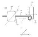
도 10은 일 실시예에 따른 스파이럴 코일 제조장치의 구성도이다.Figure 10 is a configuration diagram of a spiral coil manufacturing device according to one embodiment.
도 10을 참조하면, 스파이럴 코일 제조장치(1000)는 와이어배출기(1010) 및 곡선형성기(1020) 등을 포함할 수 있다.Referring to FIG. 10, the spiral coil manufacturing device (1000) may include a wire discharger (1010) and a curve forming device (1020).
와이어배출기(1010)는 몸체에 형성되는 일 배출구(1011)를 통해 가늘고 긴 판상의 와이어(WR)를 제1방향(X)으로 배출시킬 수 있다. 여기서, 제1방향(X)과 제2방향(Y)과 제3방향(Z)은 서로 수직된 방향일 수 있다.The wire discharger (1010) can discharge a thin and long plate-shaped wire (WR) in a first direction (X) through a discharge port (1011) formed in the body. Here, the first direction (X), the second direction (Y), and the third direction (Z) may be directions perpendicular to each other.
와이어(WR)는 제2방향(Y)으로 바라봤을 때의 너비가 제3방향(Z)으로 바라봤을 때의 두께보다 넓은 형태로 배출될 수 있다.The wire (WR) can be discharged in a form in which the width when viewed in the second direction (Y) is wider than the thickness when viewed in the third direction (Z).
곡선형성기(1020)는 배출구(1011)에서 제1방향(X)으로 연장된 지점에 곡면(1021)이 형성되어 있을 수 있다.The curve forming device (1020) may have a curved surface (1021) formed at a point extending in the first direction (X) from the discharge port (1011).
배출구(1011)에서 제1방향(X)으로 배출되는 와이어(WR)는 이러한 곡면(1021)에 곡선 형태로 휘어질 수 있다. 이렇게 와이어(WR)가 곡면(1021)에서 휘어질 때, 곡선형성기(1020)는 제1방향(X)으로 왕복운동할 수 있다.The wire (WR) discharged in the first direction (X) from the discharge port (1011) can be bent in a curved shape on the curved surface (1021). When the wire (WR) is bent in this way on the curved surface (1021), the curve forming device (1020) can reciprocate in the first direction (X).
곡선형성기(1020)가 제1방향(X)에서 배출구(1011) 쪽으로 이동하면 와이어(WR)가 형성하는 곡선의 반경은 줄어들 수 있고, 배출구(1011)의 반대쪽으로 이동하면 와이어(WR)가 형성하는 곡선의 반경은 늘어날 수 있다. 곡선형성기(1020)는 제1스파이럴층을 형성할 때, 배출구(1011)의 반대쪽으로 이동하고, 제2스파이럴층을 형성할 때, 배출구(1011) 쪽으로 이동할 수 있다.When the curve former (1020) moves toward the discharge port (1011) in the first direction (X), the radius of the curve formed by the wire (WR) may decrease, and when it moves to the opposite side of the discharge port (1011), the radius of the curve formed by the wire (WR) may increase. When forming the first spiral layer, the curve former (1020) may move to the opposite side of the discharge port (1011), and when forming the second spiral layer, it may move toward the discharge port (1011).
와이어배출기(1010)는 몸체를 제1방향(X)에 수직인 제2방향(Y)으로 왕복 운동시킬 수 있다. 여기서, 제1방향(X)은 와이어(WR)의 길이 방향이고 제2방향(Y)은 와이어(WR)의 두께 방향이고, 제3방향(Z)은 와이어(WR)의 너비 방향일 수 있다. 와이어배출기(1010)가 제2방향(Y)으로 이동하면서 각 스파이럴층의 높이를 형성할 수 있다.The wire ejector (1010) can reciprocate the body in a second direction (Y) perpendicular to the first direction (X). Here, the first direction (X) may be the length direction of the wire (WR), the second direction (Y) may be the thickness direction of the wire (WR), and the third direction (Z) may be the width direction of the wire (WR). As the wire ejector (1010) moves in the second direction (Y), the height of each spiral layer can be formed.
도면에 도시되지 않았으나, 스파이럴 코일 제조장치(1000)는 일정 간격으로 와이어(WR)를 컷팅하는 커터를 더 포함할 수 있다.Although not shown in the drawing, the spiral coil manufacturing device (1000) may further include a cutter for cutting the wire (WR) at regular intervals.
이러한 커터의 컷팅에 의해 스파이럴 코일 인덕터가 1개씩 생산될 수 있다.By cutting with these cutters, spiral coil inductors can be produced one by one.
이상에서 설명한 바와 같이 본 실시예에 의하면, 체적을 제한하면서 높은 인덕턴스를 가지는 인덕터를 제공할 수 있다. 그리고, 본 실시예에 의하면, 정전척 히팅장치에 사용되는 필터로서 체적이 작으면서 필터링 효율은 높은 필터를 제공할 수 있다. 그리고, 본 실시예에 의하면, 간단한 기구를 이용하여 체적이 작으면서 인덕턴스가 큰 코일을 제조할 수 있다.As described above, according to the present embodiment, an inductor having high inductance while limiting the volume can be provided. In addition, according to the present embodiment, a filter having a small volume and high filtering efficiency can be provided as a filter used in an electrostatic chuck heating device. In addition, according to the present embodiment, a coil having a small volume and high inductance can be manufactured using a simple mechanism.
이상에서 기재된 "포함하다", "구성하다" 또는 "가지다" 등의 용어는, 특별히 반대되는 기재가 없는 한, 해당 구성 요소가 내재될 수 있음을 의미하는 것이므로, 다른 구성 요소를 제외하는 것이 아니라 다른 구성 요소를 더 포함할 수 있는 것으로 해석되어야 한다. 기술적이거나 과학적인 용어를 포함한 모든 용어들은, 다르게 정의되지 않는 한, 본 발명이 속하는 기술 분야에서 통상의 지식을 가진 자에 의해 일반적으로 이해되는 것과 동일한 의미를 가진다. 사전에 정의된 용어와 같이 일반적으로 사용되는 용어들은 관련 기술의 문맥 상의 의미와 일치하는 것으로 해석되어야 하며, 본 발명에서 명백하게 정의하지 않는 한, 이상적이거나 과도하게 형식적인 의미로 해석되지 않는다.The terms "include," "comprise," or "have" as used herein, unless otherwise specifically stated, imply that the corresponding component may be included, and therefore should be construed to include other components rather than to exclude other components. All terms, including technical or scientific terms, unless otherwise defined, have the same meaning as commonly understood by a person of ordinary skill in the art to which the present invention pertains. Commonly used terms, such as terms defined in a dictionary, should be interpreted as being consistent with their meaning in the context of the relevant art, and shall not be interpreted in an ideal or overly formal sense, unless expressly defined in the present invention.
이상의 설명은 본 발명의 기술 사상을 예시적으로 설명한 것에 불과한 것으로서, 본 발명이 속하는 기술 분야에서 통상의 지식을 가진 자라면 본 발명의 본질적인 특성에서 벗어나지 않는 범위에서 다양한 수정 및 변형이 가능할 것이다. 따라서, 본 발명에 개시된 실시예들은 본 발명의 기술 사상을 한정하기 위한 것이 아니라 설명하기 위한 것이고, 이러한 실시예에 의하여 본 발명의 기술 사상의 범위가 한정되는 것은 아니다. 본 발명의 보호 범위는 아래의 청구범위에 의하여 해석되어야 하며, 그와 동등한 범위 내에 있는 모든 기술 사상은 본 발명의 권리범위에 포함되는 것으로 해석되어야 할 것이다.The above description is merely an illustrative description of the technical idea of the present invention, and those skilled in the art will appreciate that various modifications and variations may be made without departing from the essential characteristics of the present invention. Accordingly, the embodiments disclosed in the present invention are not intended to limit the technical idea of the present invention but to explain it, and the scope of the technical idea of the present invention is not limited by these embodiments. The protection scope of the present invention should be interpreted by the following claims, and all technical ideas within a scope equivalent thereto should be interpreted as being included in the scope of the rights of the present invention.
Claims (10)
Translated fromKorean상기 제1스파이럴층과 연결되면서, 상기 와이어가 형성하는 일련의 곡선이 외측으로부터 내측으로 계속 축소되면서 나아가는 제2스파이럴층
이 교번하면서 복수 개 배치되는, 스파이럴 코일 인덕터.A first spiral layer in which a series of curves formed by the wire start from the inside and continue to expand outward based on the central axis,
A second spiral layer, connected to the first spiral layer, in which a series of curves formed by the wires continue to decrease from the outside to the inside.
A spiral coil inductor with multiple alternately arranged coils.
상기 와이어는, 상기 중심축 방향의 두께가 상기 중심축에 수직된 방향으로 형성되는 너비보다 좁은 형태를 가지는, 스파이럴 코일 인덕터.In the first paragraph,
The above wire is a spiral coil inductor having a thickness in the direction of the central axis that is narrower than the width formed in a direction perpendicular to the central axis.
상기 와이어는, 상기 중심축에 수직된 방향으로 너비를 가지는 판상 형태로 보이는, 스파이럴 코일 인덕터.In the first paragraph,
The above wire is a spiral coil inductor that appears in a plate shape having a width in a direction perpendicular to the central axis.
정전척 히팅장치에 사용되는 필터.A heater that supplies power to a heating wire arranged on the inner side of a dielectric layer surrounding an ESC (electro-static chuck) electrode filters the power by using an inductor arranged in a wire connected to the heating wire, and the inductor is configured as a spiral coil in which a series of curves formed by the wire expand from the inner side to the outer side or contract from the outer side to the inner side based on a central axis.
Filter used in electrostatic chuck heating devices.
상기 배선의 공통모드잡음을 억제하는 CM(common mode)필터로 기능하는, 정전척 히팅장치에 사용되는 필터.In paragraph 4,
A filter used in an electrostatic chuck heating device, which functions as a CM (common mode) filter that suppresses common mode noise of the above wiring.
상기 인덕터는 에어 코어 인덕터인, 정전척 히팅장치에 사용되는 필터.In paragraph 4,
The above inductor is an air core inductor, a filter used in an electrostatic chuck heating device.
상기 배출구에서 상기 제1방향으로 연장된 지점에 곡면이 형성되어 있고, 상기 배출구에서 배출된 상기 와이어가 상기 곡면에 의해 곡선 형태로 휘어지며, 상기 제1방향으로 왕복 운동하면서 상기 곡선의 반경을 늘이고 줄이는 곡선형성기
를 포함하는, 스파이럴 코일 제조장치.A wire discharger that discharges a thin and long plate-shaped wire in a first direction through a discharge port formed in the body, and the body reciprocates in a second direction perpendicular to the first direction; and
A curve forming device in which a curve is formed at a point extending in the first direction from the discharge port, and the wire discharged from the discharge port is bent into a curved shape by the curved surface, and the radius of the curve is increased and decreased while reciprocating in the first direction.
A spiral coil manufacturing device comprising:
일정 간격으로 상기 와이어를 컷팅하는 커터를 더 포함하는, 스파이럴 코일 제조장치.In Article 7,
A spiral coil manufacturing device further comprising a cutter for cutting the wire at regular intervals.
컷팅에 의해 스파이럴 코일 인덕터가 형성되고,
상기 스파이럴 코일 인덕터는,
상기 와이어가 형성하는 일련의 곡선이 중심축을 기준으로 내측에서 시작하여 계속 확장되면서 외측으로 나아가는 제1스파이럴층과,
상기 제1스파이럴층과 연결되면서, 상기 와이어가 형성하는 일련의 곡선이 외측으로부터 내측으로 계속 축소되면서 나아가는 제2스파이럴층이 교번하면서 복수 개 배치되는, 스파이럴 코일 제조장치.In Article 8,
A spiral coil inductor is formed by cutting,
The above spiral coil inductor,
A first spiral layer in which a series of curves formed by the above wires start from the inside with respect to the central axis and continue to expand and move outward,
A spiral coil manufacturing device in which a plurality of second spiral layers are alternately arranged while being connected to the first spiral layer and continuously advancing from the outside to the inside in a series of curves formed by the wire.
상기 와이어배출기의 상기 제2방향 왕복 운동에 따라 상기 제1스파이럴층과 상기 제2스파이럴층이 교번하면서 배치되는, 스파이럴 코일 제조장치.In Article 9,
A spiral coil manufacturing device in which the first spiral layer and the second spiral layer are alternately arranged according to the second direction reciprocating motion of the wire discharger.
Priority Applications (2)
| Application Number | Priority Date | Filing Date | Title |
|---|---|---|---|
| KR1020230136552AKR20250053392A (en) | 2023-10-13 | 2023-10-13 | Spiral coil inductor, rf filter used in electrostatic chuck heating device, and spiral coil manufacturing device |
| PCT/KR2024/096280WO2025080083A1 (en) | 2023-10-13 | 2024-10-10 | Spiral coil inductor, rf filter used for electrostatic chuck heating device, and spiral coil manufacturing device |
Applications Claiming Priority (1)
| Application Number | Priority Date | Filing Date | Title |
|---|---|---|---|
| KR1020230136552AKR20250053392A (en) | 2023-10-13 | 2023-10-13 | Spiral coil inductor, rf filter used in electrostatic chuck heating device, and spiral coil manufacturing device |
Publications (1)
| Publication Number | Publication Date |
|---|---|
| KR20250053392Atrue KR20250053392A (en) | 2025-04-22 |
Family
ID=95396058
Family Applications (1)
| Application Number | Title | Priority Date | Filing Date |
|---|---|---|---|
| KR1020230136552APendingKR20250053392A (en) | 2023-10-13 | 2023-10-13 | Spiral coil inductor, rf filter used in electrostatic chuck heating device, and spiral coil manufacturing device |
Country Status (2)
| Country | Link |
|---|---|
| KR (1) | KR20250053392A (en) |
| WO (1) | WO2025080083A1 (en) |
Family Cites Families (4)
| Publication number | Priority date | Publication date | Assignee | Title |
|---|---|---|---|---|
| JP2006339617A (en)* | 2005-06-06 | 2006-12-14 | Murata Mfg Co Ltd | Electronic component |
| JP6027374B2 (en)* | 2012-09-12 | 2016-11-16 | 東京エレクトロン株式会社 | Plasma processing apparatus and filter unit |
| JP5555933B2 (en)* | 2012-11-02 | 2014-07-23 | 福井県 | Winding manufacturing method and manufacturing apparatus |
| GB202020393D0 (en)* | 2020-12-22 | 2021-02-03 | Nicoventures Trading Ltd | Inductor coil |
- 2023
- 2023-10-13KRKR1020230136552Apatent/KR20250053392A/enactivePending
- 2024
- 2024-10-10WOPCT/KR2024/096280patent/WO2025080083A1/enactivePending
Also Published As
| Publication number | Publication date |
|---|---|
| WO2025080083A1 (en) | 2025-04-17 |
Similar Documents
| Publication | Publication Date | Title |
|---|---|---|
| JP6027374B2 (en) | Plasma processing apparatus and filter unit | |
| US9530619B2 (en) | Plasma processing apparatus and filter unit | |
| TWI851602B (en) | High voltage filter assembly | |
| JP7029340B2 (en) | Filter device and plasma processing device | |
| CN102076162B (en) | Plasma treatment device | |
| JP6001932B2 (en) | Plasma processing apparatus and filter unit | |
| JP6530859B2 (en) | Plasma processing system | |
| KR102593142B1 (en) | Apparatus for treating substrate and method for controlling temperature of ferrite core | |
| US9754766B2 (en) | Plasma processing apparatus | |
| CN114388326A (en) | Plasma processing apparatus and antenna assembly | |
| KR102610976B1 (en) | High Power RF Spiral Coil Filter | |
| KR101533684B1 (en) | Compound plasma reactor | |
| KR20160010254A (en) | Apparatus for treating substrate and filter manufacturing method | |
| KR20250053392A (en) | Spiral coil inductor, rf filter used in electrostatic chuck heating device, and spiral coil manufacturing device | |
| TWI577247B (en) | Apparatus for generating plasma using dual plasma source and apparatus for treating substrate including the same | |
| JP7190566B2 (en) | Induction coil assembly and reaction chamber | |
| CN214542120U (en) | An inductively coupled plasma device | |
| TWI646777B (en) | Filter circuit, heating circuit and semiconductor processing device | |
| JP2022061463A (en) | Plasma processing equipment and plasma processing coil | |
| TW201714235A (en) | Magnetized edge ring for extreme edge control | |
| TWI795810B (en) | Heating device and anti-radio frequency interference method in plasma processing device | |
| CN113223916A (en) | Inductively coupled plasma device |
Legal Events
| Date | Code | Title | Description |
|---|---|---|---|
| PG1501 | Laying open of application | St.27 status event code:A-1-1-Q10-Q12-nap-PG1501 | |
| PE0902 | Notice of grounds for rejection | St.27 status event code:A-1-2-D10-D21-exm-PE0902 |