KR20250044302A - Driving robot - Google Patents
Driving robotDownload PDFInfo
- Publication number
- KR20250044302A KR20250044302AKR1020257004974AKR20257004974AKR20250044302AKR 20250044302 AKR20250044302 AKR 20250044302AKR 1020257004974 AKR1020257004974 AKR 1020257004974AKR 20257004974 AKR20257004974 AKR 20257004974AKR 20250044302 AKR20250044302 AKR 20250044302A
- Authority
- KR
- South Korea
- Prior art keywords
- tray
- frame
- driving robot
- driving
- paragraph
- Prior art date
- Legal status (The legal status is an assumption and is not a legal conclusion. Google has not performed a legal analysis and makes no representation as to the accuracy of the status listed.)
- Pending
Links
Images


Classifications
- B—PERFORMING OPERATIONS; TRANSPORTING
- B25—HAND TOOLS; PORTABLE POWER-DRIVEN TOOLS; MANIPULATORS
- B25J—MANIPULATORS; CHAMBERS PROVIDED WITH MANIPULATION DEVICES
- B25J9/00—Programme-controlled manipulators
- B—PERFORMING OPERATIONS; TRANSPORTING
- B25—HAND TOOLS; PORTABLE POWER-DRIVEN TOOLS; MANIPULATORS
- B25J—MANIPULATORS; CHAMBERS PROVIDED WITH MANIPULATION DEVICES
- B25J11/00—Manipulators not otherwise provided for
- B—PERFORMING OPERATIONS; TRANSPORTING
- B25—HAND TOOLS; PORTABLE POWER-DRIVEN TOOLS; MANIPULATORS
- B25J—MANIPULATORS; CHAMBERS PROVIDED WITH MANIPULATION DEVICES
- B25J11/00—Manipulators not otherwise provided for
- B25J11/008—Manipulators for service tasks
- B—PERFORMING OPERATIONS; TRANSPORTING
- B25—HAND TOOLS; PORTABLE POWER-DRIVEN TOOLS; MANIPULATORS
- B25J—MANIPULATORS; CHAMBERS PROVIDED WITH MANIPULATION DEVICES
- B25J13/00—Controls for manipulators
- B25J13/08—Controls for manipulators by means of sensing devices, e.g. viewing or touching devices
- B—PERFORMING OPERATIONS; TRANSPORTING
- B25—HAND TOOLS; PORTABLE POWER-DRIVEN TOOLS; MANIPULATORS
- B25J—MANIPULATORS; CHAMBERS PROVIDED WITH MANIPULATION DEVICES
- B25J19/00—Accessories fitted to manipulators, e.g. for monitoring, for viewing; Safety devices combined with or specially adapted for use in connection with manipulators
- B25J19/005—Accessories fitted to manipulators, e.g. for monitoring, for viewing; Safety devices combined with or specially adapted for use in connection with manipulators using batteries, e.g. as a back-up power source
- B—PERFORMING OPERATIONS; TRANSPORTING
- B25—HAND TOOLS; PORTABLE POWER-DRIVEN TOOLS; MANIPULATORS
- B25J—MANIPULATORS; CHAMBERS PROVIDED WITH MANIPULATION DEVICES
- B25J19/00—Accessories fitted to manipulators, e.g. for monitoring, for viewing; Safety devices combined with or specially adapted for use in connection with manipulators
- B25J19/02—Sensing devices
- B—PERFORMING OPERATIONS; TRANSPORTING
- B25—HAND TOOLS; PORTABLE POWER-DRIVEN TOOLS; MANIPULATORS
- B25J—MANIPULATORS; CHAMBERS PROVIDED WITH MANIPULATION DEVICES
- B25J5/00—Manipulators mounted on wheels or on carriages
- B—PERFORMING OPERATIONS; TRANSPORTING
- B25—HAND TOOLS; PORTABLE POWER-DRIVEN TOOLS; MANIPULATORS
- B25J—MANIPULATORS; CHAMBERS PROVIDED WITH MANIPULATION DEVICES
- B25J9/00—Programme-controlled manipulators
- B25J9/0009—Constructional details, e.g. manipulator supports, bases
- G—PHYSICS
- G01—MEASURING; TESTING
- G01G—WEIGHING
- G01G5/00—Weighing apparatus wherein the balancing is effected by fluid action
- G01G5/003—Weighing apparatus wherein the balancing is effected by fluid action load-cell construction or mountings
Landscapes
- Engineering & Computer Science (AREA)
- Robotics (AREA)
- Mechanical Engineering (AREA)
- Human Computer Interaction (AREA)
- Physics & Mathematics (AREA)
- General Physics & Mathematics (AREA)
- Manipulator (AREA)
Abstract
Translated fromKorean
Description
Translated fromKorean본 발명은 조립 및 분리 구조가 간결하여 유지보수가 용이하고 실장공간의 공간활용을 합리적으로 구성한 주행로봇에 관한 것이다.The present invention relates to a driving robot having a simple assembly and disassembly structure, making maintenance easy, and rationally configuring space utilization of the mounting space.
공장 자동화의 일 부분을 담당하기 위해, 로봇은 산업용으로 개발되어 왔다. 최근에는 로봇을 응용한 분야가 더욱 확대되고 있는바, 의료용 로봇과 우주항공용 로봇뿐만 아니라 일상 생활에서 사용될 수 있는 로봇도 개발되고 있다.To take part in factory automation, robots have been developed for industrial use. Recently, the application fields of robots have expanded, and in addition to medical robots and aerospace robots, robots that can be used in daily life are also being developed.
이러한 일상 생활용 로봇은 사용자의 명령에 응답하여 특정 서비스(예를 들어, 쇼핑, 서빙, 대화, 청소 등)를 제공할 수 있도록 개발되고 있다. 특정 장소에서 고정적으로 반복작업을 하는 산업용 로봇이나, 의료용이나 우주 항공용과 같이 고가의 비용을 들여 특정한 전문적인 기능을 수행하는 것과 달리 일상 생활용 로봇은 주행기능, 소통기능이 중요하며 제조 비용도 너무 과도한 경우 보급이 어려운 문제가 있다.These daily life robots are being developed to respond to user commands and provide specific services (e.g., shopping, serving, conversation, cleaning, etc.). Unlike industrial robots that perform fixed, repetitive tasks in specific locations or robots for medical or aerospace purposes that perform specific, specialized functions at high cost, daily life robots have important driving and communication functions, and if the manufacturing cost is too high, it is difficult to distribute them.
특히 사람과 같이 이족보행을 하지 않고 바퀴를 이용하여 이동하므로 바닥의 요철을 넘는 동작이나 장애물을 피해서 이동할 수 있어야 하여 바닥의 요철을 넘더라도 넘어지지 않고 충격을 최소화 할 수 있어야 하고, 장애물을 피할 수 있도록 여러 센서를 이용하여 빠른 판단을 할 수 있어야 한다.In particular, since it does not walk on two legs like humans but moves using wheels, it must be able to move over uneven ground and avoid obstacles. Even if it goes over uneven ground, it must be able to minimize impact without falling over, and it must be able to make quick decisions using multiple sensors to avoid obstacles.
이러한 로봇의 일 예로 최근 개발이 활발히 이루어지는 로봇은 국수나 스프 등의 액체류 음식이 담긴 그릇을 운반할 수 있는 주행로봇이다. 음식이 담긴 그릇은 로봇에 구비된 트레이에 올려질 수 있고, 로봇은 고객이나 서비스 제공자에게 음식을 운반할 수 있다.An example of such robots that has been actively developed recently is a mobile robot that can carry bowls containing liquid food such as noodles or soup. The bowls containing the food can be placed on a tray provided by the robot, and the robot can carry the food to customers or service providers.
음식을 운반하는 주행로봇은 실내에서 주로 이용하나 음식이 쏟아지거나 장애물과 충돌에 의한 고장이 발생할 수 있어, 수리를 위해 분해해야할 상황이 발생한다. 이때 분해 및 재조립이 어려운 경우 유지보수 시간이 오래 걸리고 기능이 정상적으로 작동하지 않을 수 있다.Food-transporting mobile robots are mainly used indoors, but they can break down due to food spilling or collisions with obstacles, and thus need to be disassembled for repair. If disassembly and reassembly are difficult, maintenance time can be long and functions may not function properly.
본 발명은 조립 및 분리 구조가 간결하여 유지보수가 용이하고 실장공간의 공간활용을 합리적으로 구성한 주행로봇을 제공하는 것을 목적으로 한다.The purpose of the present invention is to provide a driving robot that is easy to maintain due to its simple assembly and disassembly structure and has a rational configuration for space utilization of the installation space.
하부 하우징; 상기 하부 하우징 내부에 위치하는 프레임 조립체; 상기 프레임 조립체의 하부에 위치하는 주행부; 상기 하부 하우징의 상부에 결합하여 상측으로 연장된 트레이 프레임; 상기 트레이 프레임에 결합된 로드셀; 상기 로드셀의 상부에 결합하는 무빙 브라켓; 및 상기 무빙 브라켓에 결합되며 상기 트레이 프레임의 체결홀을 통해 돌출되는 트레이 홀더; 및 상기 트레이 홀더에 안착되는 트레이 모듈을 포함하는 주행로봇을 제공한다.A driving robot is provided, which includes a lower housing; a frame assembly positioned inside the lower housing; a driving member positioned at a lower portion of the frame assembly; a tray frame coupled to an upper portion of the lower housing and extending upward; a load cell coupled to the tray frame; a moving bracket coupled to an upper portion of the load cell; and a tray holder coupled to the moving bracket and protruding through a fastening hole of the tray frame; and a tray module mounted on the tray holder.
상기 트레이 프레임은 복수개의 체결홀을 포함하고, 상기 무빙 브라켓은 상기 체결홀에 상응하는 위치에 형성되며 상기 트레이 홀더 체결부를 복수개 포함할 수 있다.The above tray frame includes a plurality of fastening holes, and the moving bracket is formed at a position corresponding to the fastening holes and may include a plurality of tray holder fastening portions.
상기 복수개의 체결 홀 중 상기 트레이 홀더가 결합하지 않은 체결홀을 커버하는 홀커버를 포함할 수 있다.The above may include a hole cover that covers a fastening hole among the plurality of fastening holes to which the tray holder is not coupled.
상기 로드셀은 가압시 형상이 변화하는 탄성바디; 및 상기 탄성바디의 변형에 따라 전기신호를 생성하는 스트레인게이지를 포함할 수 있다.The above load cell may include an elastic body whose shape changes when pressurized; and a strain gauge that generates an electric signal according to the deformation of the elastic body.
상기 탄성바디는 전방에서 후방으로 연장된 제1 슬롯 및 후방에서 전방으로 연장된 제2 슬롯을 포함하는 Z자 형상을 가질 수 있다.The above elastic body may have a Z-shape including a first slot extending from the front to the rear and a second slot extending from the rear to the front.
상기 트레이 프레임은 상기 무빙 브라켓과 마주하는 면에 형성되며 수직방향으로 연장된 스토퍼 홈을 포함하고, 상기 무빙 브라켓은 상기 트레이 프레임의 스토퍼 홈 방향으로 돌출된 스토퍼 범프를 포함하며, 상기 스토퍼 홈의 너비는 상기 스토퍼 범프의 너비 보다 넓게 형성할 수 있다.The above tray frame is formed on a surface facing the above moving bracket and includes a stopper groove extending in a vertical direction, the above moving bracket includes a stopper bump protruding in the direction of the stopper groove of the above tray frame, and the width of the stopper groove can be formed to be wider than the width of the stopper bump.
상기 트레이 프레임에 고정되는 고정 브라켓을 포함하며, 상기 고정 브라켓의 상부에 체결되어 상기 트레이 프레임에 결합될 수 있다.It includes a fixed bracket fixed to the above tray frame, and can be connected to the upper part of the fixed bracket and coupled to the tray frame.
상기 트레이 프레임은 상단이 하단 보다 배면방향에 위치하도록 기울어지고 상기 체결홀은 상기 트레이 프레임의 연장방향에 수직 방향으로 형성되며, 상기 트레이 홀더는 중력방향에 수직방향으로 편평한 받침부를 포함할 수 있다.The above tray frame is inclined so that the upper part is positioned toward the back more than the lower part, the above fastening hole is formed in a direction perpendicular to the extension direction of the tray frame, and the above tray holder may include a flat support part perpendicular to the direction of gravity.
상기 트레이 모듈의 하부에 위치하며 전후방향으로 연장되고 상기 트레이 홀더와 체결되는 트레이 체결부를 포함하는 트레이 바를 포함하고, 상기 트레이 체결부는 전후 방향으로 복수개가 형성될 수 있다.The tray bar includes a tray fastening portion positioned at the bottom of the tray module and extending in the front-back direction and fastened to the tray holder, and a plurality of tray fastening portions can be formed in the front-back direction.
상기 프레임 조립체에 결합되는 배터리; 상기 프레이 조립체에 결합되며 상기 배터리의 상부에 위치하는 기판모듈; 및 상기 로드셀부터 상기 트레이 프레임을 통해 상기 기판모듈과 연결하는 케이블을 포함할 수 있다.It may include a battery coupled to the frame assembly; a substrate module coupled to the frame assembly and positioned above the battery; and a cable connecting the load cell to the substrate module through the tray frame.
상기 트레이 프레임은 좌우 한 쌍 구비하고, 상기 한 쌍의 트레이 프레임 상단을 연결하는 헤드 프레임; 및 상기 헤드 프레임에 형성된 상부 바스켓을 포함할 수 있다.The above tray frame may include a left and right pair, a head frame connecting the upper ends of the pair of tray frames; and an upper basket formed on the head frame.
상기 상부 바스켓의 전면에 위치하는 디스플레이를 포함할 수 있다.It may include a display positioned on the front of the upper basket.
상기 트레이 프레임은 좌우 한 쌍 구비하고, 상기 트레이 모듈, 상기 하부 하우징 및 상기 한 쌍의 트레이 프레임 사이 공간에 삽입되는 슬라이드 바스켓을 더 포함할 수 있다.The above tray frame may be provided with a left and right pair, and may further include a slide basket inserted into a space between the tray module, the lower housing, and the pair of tray frames.
본 발명의 주행로봇은 로드셀을 구비하여 트레이 상에 놓인 물체의 유무나 추락, 전복 등을 감지할 수 있어 안정적인 주행을 수행할 수 있다.The driving robot of the present invention is equipped with a load cell so that it can detect the presence or absence of an object placed on a tray, or whether it has fallen or overturned, and thus can perform stable driving.
또한, 사용자가 원하는 간격으로 트레이 모듈의 위치를 변경할 수 있어, 활용도가 개선될 수 있다.Additionally, the user can change the position of the tray module at desired intervals, which can improve usability.
또한, 트레이 모듈의 위치 변경시 로드셀을 탈착하지 않고 손쉽게 변경할 수 있어 트레이 모듈 변경의 편의성도 개선될 수 있다. 본 발명에서 얻을 수 있는 효과는 이상에서 언급한 효과들로 제한되지 않으며, 언급하지 않은 또 다른 효과들은 아래의 기재로부터 본 발명이 속하는 기술분야에서 통상의 지식을 가진 자에게 명확하게 이해될 수 있을 것이다.In addition, since the load cell can be easily changed without removing it when changing the position of the tray module, the convenience of changing the tray module can also be improved. The effects that can be obtained from the present invention are not limited to the effects mentioned above, and other effects that are not mentioned can be clearly understood by those skilled in the art to which the present invention belongs from the description below.
도 1은 본 발명의 일 실시예에 따른 5G 네트워크 기반의 클라우드 시스템을 나타내는 도면이다.
도 2는 본 발명의 일 실시 예에 따른 주행로봇의 구성을 설명하기 위한 도면이다.
도 3은 본 발명의 일 실시 예에 따른 주행로봇의 전면 사시도이다.
도 4는 본 발명의 일 실시 예에 따른 주행로봇의 후면 사시도이다.
도 5는 본 발명의 일 실시 예에 따른 주행로봇의 분해 사시도이다.
도 6은 본 발명의 일 실시 예에 따른 주행로봇의 하측부의 분해사시도이다.
도 7은 본 발명의 일 실시 예에 따른 주행로봇의 트레이 모듈과 그 체결구조를 도시한 분해사시도이다.
도 8은 본 발명의 일 실시예에 따른 주행로봇의 트레이 프레임의 외측 커버를 분리한 상태를 도시한 도면이다.
도 9는 본 발명의 일 실시예에 따른 주행로봇의 로드셀과 브라켓의 분해사시도이다.
도 10은 본 발명의 일 실시예에 따른 주행로봇의 스토퍼 범프와 스토퍼 홈을 도시한 도면이다.FIG. 1 is a diagram illustrating a cloud system based on a 5G network according to one embodiment of the present invention.
FIG. 2 is a drawing for explaining the configuration of a driving robot according to one embodiment of the present invention.
Figure 3 is a front perspective view of a driving robot according to one embodiment of the present invention.
Figure 4 is a rear perspective view of a driving robot according to one embodiment of the present invention.
Figure 5 is an exploded perspective view of a driving robot according to one embodiment of the present invention.
Figure 6 is an exploded perspective view of the lower part of a driving robot according to one embodiment of the present invention.
FIG. 7 is an exploded perspective view illustrating a tray module of a driving robot and its fastening structure according to one embodiment of the present invention.
FIG. 8 is a drawing showing a state in which the outer cover of the tray frame of a driving robot according to one embodiment of the present invention is separated.
Figure 9 is an exploded perspective view of a load cell and a bracket of a driving robot according to one embodiment of the present invention.
FIG. 10 is a drawing illustrating a stopper bump and a stopper groove of a driving robot according to one embodiment of the present invention.
이하, 첨부된 도면을 참조하여 본 명세서에 개시된 실시 예를 상세히 설명하되, 도면 부호에 관계없이 동일하거나 유사한 구성요소는 동일한 참조 번호를 부여하고 이에 대한 중복되는 설명은 생략하기로 한다. 이하의 설명에서 사용되는 구성요소에 대한 접미사 "모듈" 및 "부"는 명세서 작성의 용이함만이 고려되어 부여되거나 혼용되는 것으로서, 그 자체로 서로 구별되는 의미 또는 역할을 갖는 것은 아니다. 또한, 본 명세서에 개시된 실시 예를 설명함에 있어서 관련된 공지 기술에 대한 구체적인 설명이 본 명세서에 개시된 실시 예의 요지를 흐릴 수 있다고 판단되는 경우 그 상세한 설명을 생략한다. 또한, 첨부된 도면은 본 명세서에 개시된 실시 예를 쉽게 이해할 수 있도록 하기 위한 것일 뿐, 첨부된 도면에 의해 본 명세서에 개시된 기술적 사상이 제한되지 않으며, 본 발명의 사상 및 기술 범위에 포함되는 모든 변경, 균등물 내지 대체물을 포함하는 것으로 이해되어야 한다.Hereinafter, embodiments disclosed in this specification will be described in detail with reference to the attached drawings. Regardless of the drawing symbols, identical or similar components will be given the same reference numerals and redundant descriptions thereof will be omitted. The suffixes "module" and "part" used for components in the following description are assigned or used interchangeably only for the convenience of writing the specification, and do not have distinct meanings or roles in themselves. In addition, when describing embodiments disclosed in this specification, if it is determined that a specific description of a related known technology may obscure the gist of the embodiments disclosed in this specification, the detailed description thereof will be omitted. In addition, the attached drawings are only intended to facilitate easy understanding of the embodiments disclosed in this specification, and the technical ideas disclosed in this specification are not limited by the attached drawings, and should be understood to include all modifications, equivalents, and substitutes included in the spirit and technical scope of the present invention.
제1, 제2 등과 같이 서수를 포함하는 용어는 다양한 구성요소들을 설명하는데 사용될 수 있지만, 상기 구성요소들은 상기 용어들에 의해 한정되지는 않는다. 상기 용어들은 하나의 구성요소를 다른 구성요소로부터 구별하는 목적으로만 사용된다.Terms that include ordinal numbers, such as first, second, etc., may be used to describe various components, but the components are not limited by the terms. The terms are used only to distinguish one component from another.
어떤 구성요소가 다른 구성요소에 "연결되어" 있다거나 "접속되어" 있다고 언급된 때에는, 그 다른 구성요소에 직접적으로 연결되어 있거나 또는 접속되어 있을 수도 있지만, 중간에 다른 구성요소가 존재할 수도 있다고 이해되어야 할 것이다. 반면에, 어떤 구성요소가 다른 구성요소에 "직접 연결되어" 있다거나 "직접 접속되어" 있다고 언급된 때에는, 중간에 다른 구성요소가 존재하지 않는 것으로 이해되어야 할 것이다.When it is said that a component is "connected" or "connected" to another component, it should be understood that it may be directly connected or connected to that other component, but that there may be other components in between. On the other hand, when it is said that a component is "directly connected" or "directly connected" to another component, it should be understood that there are no other components in between.
단수의 표현은 문맥상 명백하게 다르게 뜻하지 않는 한, 복수의 표현을 포함한다.Singular expressions include plural expressions unless the context clearly indicates otherwise.
본 출원에서, "포함한다" 또는 "가지다" 등의 용어는 명세서상에 기재된 특징, 숫자, 단계, 동작, 구성요소, 부품 또는 이들을 조합한 것이 존재함을 지정하려는 것이지, 하나 또는 그 이상의 다른 특징들이나 숫자, 단계, 동작, 구성요소, 부품 또는 이들을 조합한 것들의 존재 또는 부가 가능성을 미리 배제하지 않는 것으로 이해되어야 한다.In this application, it should be understood that terms such as “comprises” or “has” are intended to specify the presence of a feature, number, step, operation, component, part or combination thereof described in the specification, but do not exclude in advance the possibility of the presence or addition of one or more other features, numbers, steps, operations, components, parts or combinations thereof.
로봇은 어떤 작업이나 조작을 자동으로 할 수 있는 기계 장치로서, 로봇은 외부의 제어 장치에 의해 조종되거나 제어 장치가 내장될 수도 있다. 기 설정된 동작만 반복하여 처리하거나 무거운 물건을 들어올리거나, 정밀한 작업의 수행 및 극한의 환경에서의 작업과 같이 인간이 수행하기 어려운 작업을 수행할 수 있다.A robot is a mechanical device that can automatically perform certain tasks or operations. The robot may be controlled by an external control device or may have a built-in control device. It can perform tasks that are difficult for humans to perform, such as repeating preset movements, lifting heavy objects, performing precision work, and working in extreme environments.
작업수행을 위해 액츄에이터 또는 모터를 포함하는 구동부를 구비하여 로봇 관절을 움직이는 등의 다양한 물리적 동작을 수행할 수 있다.A driving unit including an actuator or motor can be provided to perform various physical actions, such as moving the robot joints, to perform tasks.
로봇은 그 제조비용이 높고 조작의 전문성 등의 문제로 특정 작업에 특화된 외관을 가지는 산업용 로봇이나 의료용 로봇이 먼저 발달 되었다. 산업용, 의료용 로봇은 지정된 장소에서 동일한 동작을 반복수행하나,Robots are developed first as industrial robots or medical robots with specialized appearances for specific tasks due to high manufacturing costs and issues such as specialized operation. Industrial and medical robots perform the same movements repeatedly in a designated location, but
최근에는 이동 가능한 로봇이 등장하고 있다. 특히 우주항공산업과 같이 인간이 직접 가기 어려운 먼 행성에서 탐사작업 등을 수행할 수 있으며 이러한 로봇은 주행기능이 추가된다.Recently, mobile robots have been introduced. In particular, they can perform exploration work on distant planets where humans cannot go directly, such as in the aerospace industry, and these robots have additional driving functions.
주행기능을 수행하기 위해서는 구동부를 구비하며 휠, 브레이트, 캐스터, 모터 등을 포함할 수 있으며 주변의 장애물을 파악하고 이를 피해 주행하기 위해서는 인공지능을 탑재한 로봇이 등장하고 있다.In order to perform the driving function, a driving unit is required and may include wheels, brakes, casters, motors, etc., and robots equipped with artificial intelligence are appearing to identify obstacles in the surroundings and drive to avoid them.
인공 지능은 인공적인 지능 또는 이를 만들 수 있는 방법론을 연구하는 분야를 의미하며, 머신 러닝(기계 학습, Machine Learning)은 인공 지능 분야에서 다루는 다양한 문제를 정의하고 그것을 해결하는 방법론을 연구하는 분야를 의미한다. 머신 러닝은 어떠한 작업에 대하여 꾸준한 경험을 통해 그 작업에 대한 성능을 높이는 알고리즘으로 정의하기도 한다.Artificial intelligence refers to a field that studies artificial intelligence or the methodologies for creating it, and machine learning refers to a field that defines various problems in the field of artificial intelligence and studies the methodologies for solving them. Machine learning is also defined as an algorithm that improves the performance of a task through constant experience with that task.
인공 신경망(ANN: Artificial Neural Network)은 머신 러닝에서 사용되는 모델로써, 시냅스의 결합으로 네트워크를 형성한 인공 뉴런(노드)들로 구성되는, 문제 해결 능력을 가지는 모델 전반을 의미할 수 있다. 인공 신경망은 다른 레이어의 뉴런들 사이의 연결 패턴, 모델 파라미터를 갱신하는 학습 과정, 출력값을 생성하는 활성화 함수(Activation Function)에 의해 정의될 수 있다.An artificial neural network (ANN) is a model used in machine learning, and can refer to a model with problem-solving capabilities that is composed of artificial neurons (nodes) that form a network by combining synapses. An artificial neural network can be defined by the connection pattern between neurons in different layers, the learning process that updates model parameters, and the activation function that generates output values.
인공 신경망은 입력층(Input Layer), 출력층(Output Layer), 그리고 선택적으로 하나 이상의 은닉층(Hidden Layer)를 포함할 수 있다. 각 층은 하나 이상의 뉴런을 포함하고, 인공 신경망은 뉴런과 뉴런을 연결하는 시냅스를 포함할 수 있다.An artificial neural network may include an input layer, an output layer, and optionally one or more hidden layers. Each layer may include one or more neurons, and the artificial neural network may include synapses connecting neurons.
인공 신경망에서 각 뉴런은 시냅스를 통해 입력되는 입력 신호들, 가중치, 편향에 대한 활성 함수의 함수값을 출력할 수 있다.In an artificial neural network, each neuron can output a function value of an activation function for input signals, weights, and biases received through synapses.
모델 파라미터는 학습을 통해 결정되는 파라미터를 의미하며, 시냅스 연결의 가중치와 뉴런의 편향 등이 포함된다. 그리고, 하이퍼파라미터는 머신 러닝 알고리즘에서 학습 전에 설정되어야 하는 파라미터를 의미하며, 학습률(Learning Rate), 반복 횟수, 미니 배치 크기, 초기화 함수 등이 포함된다.Model parameters refer to parameters that are determined through learning, including the weights of synaptic connections and the biases of neurons. Hyperparameters refer to parameters that must be set before learning in machine learning algorithms, including learning rate, number of iterations, mini-batch size, and initialization functions.
인공 신경망의 학습의 목적은 손실 함수를 최소화하는 모델 파라미터를 로봇의 목적이나 사용 분야에 따라 결정하는 것으로 볼 수 있다. 손실 함수는 인공 신경망의 학습 과정에서 최적의 모델 파라미터를 결정하기 위한 지표로 이용될 수 있다.The purpose of learning an artificial neural network can be seen as determining model parameters that minimize the loss function according to the purpose or field of use of the robot. The loss function can be used as an indicator to determine the optimal model parameters during the learning process of an artificial neural network.
머신 러닝은 학습 방식에 따라 지도 학습(Supervised Learning), 비지도 학습(Unsupervised Learning), 강화 학습(Reinforcement Learning)으로 분류할 수 있다.Machine learning can be classified into supervised learning, unsupervised learning, and reinforcement learning depending on the learning method.
지도 학습은 학습 데이터에 대한 레이블(label)이 주어진 상태에서 인공 신경망을 학습시키는 방법을 의미하며, 레이블이란 학습 데이터가 인공 신경망에 입력되는 경우 인공 신경망이 추론해 내야 하는 정답(또는 결과 값)을 의미할 수 있다. 비지도 학습은 학습 데이터에 대한 레이블이 주어지지 않는 상태에서 인공 신경망을 학습시키는 방법을 의미할 수 있다. 강화 학습은 어떤 환경 안에서 정의된 에이전트가 각 상태에서 누적 보상을 최대화하는 행동 혹은 행동 순서를 선택하도록 학습시키는 학습 방법을 의미할 수 있다.Supervised learning refers to a method of training an artificial neural network when labels for training data are given. The labels can refer to the correct answer (or result value) that the artificial neural network should infer when training data is input to the artificial neural network. Unsupervised learning can refer to a method of training an artificial neural network when labels for training data are not given. Reinforcement learning can refer to a learning method that trains an agent defined in a certain environment to select actions or action sequences that maximize cumulative rewards in each state.
인공 신경망 중에서 복수의 은닉층을 포함하는 심층 신경망(DNN: Deep Neural Network)으로 구현되는 머신 러닝을 딥 러닝(심층 학습, Deep Learning)이라 부르기도 하며, 딥 러닝은 머신 러닝의 일부이다. 이하에서, 머신 러닝은 딥러닝을 포함하는 의미로 사용된다.Machine learning implemented with a deep neural network (DNN: Deep Neural Network) that includes multiple hidden layers among artificial neural networks is also called deep learning, and deep learning is a part of machine learning. Hereinafter, machine learning is used to mean including deep learning.
로봇은 AI 기술이 적용되어, 안내 로봇, 운반 로봇, 청소 로봇, 웨어러블 로봇, 엔터테인먼트 로봇, 펫 로봇, 무인 비행 로봇 등으로 구현될 수 있다.Robots can be implemented as guide robots, transport robots, cleaning robots, wearable robots, entertainment robots, pet robots, and unmanned flying robots by applying AI technology.
로봇은 동작을 제어하기 위한 로봇 제어 모듈을 포함할 수 있고, 로봇 제어 모듈은 소프트웨어 모듈 또는 이를 하드웨어로 구현한 칩을 의미할 수 있다.The robot may include a robot control module for controlling movements, and the robot control module may mean a software module or a chip implementing the same as hardware.
로봇은 다양한 종류의 센서들로부터 획득한 센서 정보를 이용하여 로봇의 상태 정보를 획득하거나, 주변 환경 및 객체를 검출(인식)하거나, 맵 데이터를 생성하거나, 이동 경로 및 주행 계획을 결정하거나, 사용자 상호작용에 대한 응답을 결정하거나, 동작을 결정할 수 있다.Robots can use sensor information acquired from various types of sensors to acquire robot status information, detect (recognize) the surrounding environment and objects, generate map data, determine movement paths and driving plans, determine responses to user interactions, or determine actions.
로봇은 적어도 하나 이상의 인공 신경망으로 구성된 학습 모델을 이용하여 상기한 동작들을 수행할 수 있다. 예컨대, 로봇은 학습 모델을 이용하여 주변 환경 및 객체를 인식할 수 있고, 인식된 주변 환경 정보 또는 객체 정보를 이용하여 동작을 결정할 수 있다. 여기서, 학습 모델은 로봇에서 직접 학습되거나, AI 서버등의 외부 장치에서 학습된 것일 수 있다.The robot can perform the above-described actions using a learning model composed of at least one artificial neural network. For example, the robot can recognize the surrounding environment and objects using the learning model, and determine actions using the recognized surrounding environment information or object information. Here, the learning model can be learned directly by the robot or learned from an external device such as an AI server.
이때, 로봇은 직접 학습 모델을 이용하여 결과를 생성하여 동작을 수행할수도 있지만, AI 서버 등의 외부 장치에 센서 정보를 전송하고 그에 따라 생성된 결과를 수신하여 동작을 수행할 수도 있다.At this time, the robot can perform actions by generating results using a direct learning model, but it can also transmit sensor information to an external device such as an AI server and perform actions by receiving the results generated accordingly.
인공 지능을 통해 로봇은 자율주행을 수행할 수 있다. 스스로 최적의 경로를 판단하고 장애물을 피해서 이동 가능한 기술을 의미하며 현재 적용되고 있는 자율주행 기술은 주행중인 차선을 유지하는 기술, 어댑티브 크루즈 컨트롤과 같이 속도를 자동으로 조절하는 기술, 정해진 경로를 따라 자동으로 주행하는 기술, 목적지가 설정되면 자동으로 경로를 설정해주는 주행기술 등이 모두 포함될 수 있다.Through artificial intelligence, robots can perform autonomous driving. This refers to technology that can determine the optimal path on its own and move while avoiding obstacles. Currently applied autonomous driving technology can include technology that maintains the driving lane, technology that automatically adjusts speed such as adaptive cruise control, technology that automatically drives along a set path, and driving technology that automatically sets a path when a destination is set.
자율주행을 수행하기 위해서는 주변상황의 데이터를 인지하기 위해 수많은 센서를 포함할 수 있다. 센서로는 근접 센서, 조도 센서, 가속도 센서, 자기센서, 자이로 센서, 관성 센서, RGB 센서, IR 센서, 지문 인식 센서, 초음파 센서, 광 센서, 마이크로폰, 라이다, 레이더 등을 들 수 있다.In order to perform autonomous driving, numerous sensors may be included to recognize data from the surroundings. Sensors include proximity sensors, light sensors, acceleration sensors, magnetic sensors, gyro sensors, inertial sensors, RGB sensors, IR sensors, fingerprint recognition sensors, ultrasonic sensors, light sensors, microphones, lidar, radar, etc.
센서에서 수집한 정보 이외에 RGBC카메라, 적외선 카메라 등을 통해 수집한 영상정보와 마이크로폰을 통해 수집한 음향정보를 통해 자율주행을 수행할 수 있다. 또한, 사용자 입력부를 통해 입력된 정보에 기초하여 주행할 수 있다. 무선통신부를 통해 수집한 맵 데이터, 위치정보 및 주변 상황의 정보 등 또한 자율주행 수행에 필요한 정보들이다.In addition to the information collected from the sensor, autonomous driving can be performed using image information collected through RGBC cameras, infrared cameras, etc., and audio information collected through microphones. In addition, driving can be performed based on information entered through the user input section. Map data, location information, and information on the surrounding situation collected through the wireless communication section are also necessary information for autonomous driving.
맵 데이터에는 로봇이 이동하는 공간에 배치된 다양한 객체들에 대한 객체 식별 정보가 포함될 수 있다. 예컨대, 맵 데이터에는 벽, 문 등의 고정 객체들과 화분, 책상 등의 이동 가능한 객체들에 대한 객체 식별 정보가 포함될 수 있다. 그리고, 객체 식별 정보에는 명칭, 종류, 거리, 위치 등이 포함될 수 있다.Map data may include object identification information for various objects placed in the space where the robot moves. For example, map data may include object identification information for fixed objects such as walls and doors, and movable objects such as flower pots and desks. In addition, object identification information may include name, type, distance, location, etc.
따라서 로봇은 인공지능이 학습할 수 있는 데이터를 수집하기 위해 센서 및 다양한 입력부 그리고 무선통신부 등을 필수적으로 구비하고 각종정보를 종합하여 최적의 동작을 수행할 수 있다. 인공지능을 수행하는 러닝 프로세서는 로봇내의 제어부에 탑재하여 학습을 수행할 수도 있고, 수집한 정보를 서보로 전송하고 서버를 통해 학습하여 학습결과를 로봇에 다시 전송하여 이를 기초로 자율주행을 수행할 수 있다.Therefore, the robot is equipped with sensors, various input units, and wireless communication units to collect data that AI can learn from, and can perform optimal operations by synthesizing various information. The learning processor that performs AI can be installed in the control unit within the robot to perform learning, or the collected information can be transmitted to the servo, learned through the server, and the learning results can be sent back to the robot to perform autonomous driving based on this.
인공지능을 구비한 로보트는 새로운 장소에서도 주변 정보를 수집하여 전체 맵을 구현할 수 있으며, 주요활동반경의 장소는 누적되는 정보량이 많아 보다 정확한 자율주행을 수행할 수 있다.Robots equipped with artificial intelligence can collect information about their surroundings even in new locations and create a full map, and can perform more accurate autonomous driving in places with a large accumulated amount of information in the main activity radius.
사용자 입력을 받기위해 터치스크린이나 버튼을 구비할 수 있으며 사용자의 음성을 인식하여 명령을 입력받을 수도 있다. 프로세서는 음성입력을 문자열로 변환하기 위해 STT(Speech To Text) 엔진 또는 자연어의 의도 정보를 획득하기 위한 자연어 처리(NLP: Natural Language Processing) 엔진 중에서 적어도 하나 이상을 이용하여, 사용자 입력에 상응하는 의도 정보를 획득할 수 있다.A touch screen or buttons may be provided to receive user input, and commands may be received by recognizing the user's voice. The processor may use at least one of an STT (Speech To Text) engine to convert voice input into a string, or a natural language processing (NLP) engine to obtain intention information of natural language, to obtain intention information corresponding to the user input.
이때, STT 엔진 또는 NLP 엔진 중에서 적어도 하나 이상은 적어도 일부가 머신 러닝 알고리즘에 따라 학습된 인공 신경망으로 구성될 수 있다. 그리고, STT 엔진 또는 NLP 엔진 중에서 적어도 하나 이상은 러닝 프로세서에 의해 학습된 것이나, AI 서버의 러닝 프로세서에 의해 학습된 것이거나, 또는 이들의 분산 처리에 의해 학습된 것일 수 있다.At this time, at least one of the STT engine or the NLP engine may be configured with an artificial neural network at least partially learned according to a machine learning algorithm. And, at least one of the STT engine or the NLP engine may be learned by a learning processor, by a learning processor of an AI server, or by distributed processing thereof.
도 1은 본 발명의 일 실시 예에 따른 5G 네트워크 기반의 클라우드 시스템(1000)을 나태낸다.FIG. 1 illustrates a cloud system (1000) based on a 5G network according to one embodiment of the present invention.
도 1을 참고하면, 클라우드 시스템(1000)은 주행로봇(100), 이동 단말(300), 로봇 관제 시스템(200), 각종 기기(400) 및 5G 네트워크(500)를 포함할 수 있다.주행로봇(100)은 물품을 출발지에서 목적지로 운반하는 로봇이다.Referring to FIG. 1, a cloud system (1000) may include a driving robot (100), a mobile terminal (300), a robot control system (200), various devices (400), and a 5G network (500). The driving robot (100) is a robot that transports items from a starting point to a destination.
(100)은 주행로봇(100)이 물건을 배송하는 운송 로봇인 경우 물류 센터에서 직접 목적지까지 이동할 수 있으며, 물류 센터에서 물품 목적지 주변까지 차량에 적재되어 이동한 후, 목적지 주변에서 하차하여 목적지까지 이동할 수 있다.(100) If the driving robot (100) is a transport robot that delivers goods, it can move directly from the logistics center to the destination, and after being loaded onto a vehicle and moved from the logistics center to the vicinity of the goods destination, it can be unloaded around the destination and moved to the destination.
또한, 주행로봇(100)은 실외뿐만 아니라 실내에서도 물품을 목적지로 이동할 수 있다. 주행로봇(100)은 AGV(Automated Guided Vehicle)로 구현될 수 있으며, AGV는 바닥면의 센서, 자기장, 비전기기 등에 의해 움직이는 운송 장치일 수 있다.In addition, the driving robot (100) can move items to a destination not only outdoors but also indoors. The driving robot (100) can be implemented as an AGV (Automated Guided Vehicle), and the AGV can be a transport device that moves by sensors, magnetic fields, vision devices, etc. on the floor.
주행로봇(100)이 음식을 운반하는 서빙 로봇인 경우 실내의 테이블과 같은 고정된 장애물과 사람을 피하여 안전하게 그릇을 운반해야한다. 그릇을 안착하기 위한 트레이가 있으며, 운송로봇과 달리 쉽게 넣고 빼고 할 수 있도록 커버가 생략되어 있다.If the driving robot (100) is a serving robot that transports food, it must safely transport the dishes while avoiding fixed obstacles such as tables indoors and people. There is a tray for placing the dishes, and unlike a transport robot, the cover is omitted so that it can be easily put in and taken out.
또한, 그릇은 상부가 개방되어 있어 기울어지거나 넘어지는 경우 운송 로봇보다 더욱 안정적인 운행이 가능하도록 부드러운 주행을 수행할 수 있어야 한다.Additionally, the bowl must be open at the top, allowing for smooth movement to enable more stable operation than a transport robot in case of tilting or tipping.
이동 단말(300)은 5G 네트워크(500)를 통해 주행로봇(100)과 통신할 수 있다. 이동 단말(300)은 물품을 적재하기 위해 파티션을 보관 영역에 설치하는 사용자가 소지한 기기 또는 적재된 물품의 수령자가 소지한 기기일 수 있다. 이동 단말(300)은 영상 기반으로 정보를 제공할 수 있으며, 이동 단말(300)은 휴대폰, 스마트 폰(smart phone), 웨어러블 디바이스(wearable device, 예를 들어, 워치형 단말기 (smartwatch), 글래스형 단말기 (smart glass), HMD(head mounted display)) 등의 이동형 기기들을 포함할 수 있다.The mobile terminal (300) can communicate with the driving robot (100) via the 5G network (500). The mobile terminal (300) can be a device carried by a user who installs a partition in a storage area to load items, or a device carried by a recipient of loaded items. The mobile terminal (300) can provide information based on images, and the mobile terminal (300) can include mobile devices such as a mobile phone, a smart phone, a wearable device (e.g., a smartwatch, a smart glass, a head mounted display (HMD)).
로봇 관제 시스템(200)는 주행로봇(100)을 원격으로 제어할 수 있으며, 주행로봇(100)의 다양한 요청에 응답할 수 있다. 예를 들면, 로봇 관제 시스템(200)은 주행로봇(100)의 요청에 기초하여, 인공 지능을 이용한 연산을 수행할 수 있다.The robot control system (200) can remotely control the driving robot (100) and respond to various requests of the driving robot (100). For example, the robot control system (200) can perform calculations using artificial intelligence based on requests of the driving robot (100).
또한, 로봇 관제 시스템(200)은 주행로봇(100)의 이동 경로를 설정할 수 있으며, 로봇 관제 시스템(200)은 복수의 목적지가 있는 경우, 목적지의 이동 순서를 설정할 수 있다.In addition, the robot control system (200) can set the movement path of the driving robot (100), and, if there are multiple destinations, the robot control system (200) can set the movement order of the destinations.
각종 기기(400)는 개인 컴퓨터(PC, 400a), 자율 주행차(400b), 홈 로봇(400c) 등을 포함할 수 있다. 주행로봇(100)은 물품의 운송 목적지에 도착하는 경우, 홈 로봇(400c)과의 통신을 통해 홈 로봇(400c)에 직접 물품을 전달할 수 있다.The various devices (400) may include a personal computer (PC, 400a), an autonomous vehicle (400b), a home robot (400c), etc. When the driving robot (100) arrives at the transport destination of the goods, it can directly deliver the goods to the home robot (400c) through communication with the home robot (400c).
각종 기기(400)는 주행로봇(100), 이동 단말(300), 로봇 관제 시스템(200) 등과 5G 네트워크(500)를 통해 유무선으로 연결될 수 있다.Various devices (400) can be connected wirelessly or wiredly to a driving robot (100), a mobile terminal (300), a robot control system (200), etc. through a 5G network (500).
상기 주행로봇(100), 이동 단말(300), 로봇 관제 시스템(200) 및 각종 기기(400)는 모두 5G 모듈을 탑재하여 100Mbps 내지 20Gbps(또는, 그 이상) 속도로 데이터를 송수신할 수 있어서 대용량의 동영상 파일을 다양한 기기로 전송할 수 있으며, 저전력으로 구동되어 전력 소비가 최소화되게 할 수 있다. 다만, 상기 전송 속도는 실시 예에 따라 달리 구현될 수 있다.The above-mentioned driving robot (100), mobile terminal (300), robot control system (200), and various devices (400) are all equipped with 5G modules to transmit and receive data at a speed of 100 Mbps to 20 Gbps (or higher), so that large-capacity video files can be transmitted to various devices, and power consumption can be minimized by operating at low power. However, the transmission speed may be implemented differently depending on the embodiment.
5G 네트워크(500)는 5G 이동 통신 네트워크, 근거리 네트워크, 인터넷 등을 포함할 수 있으며, 유무선으로 기기들의 통신 환경을 제공할 수 있다.The 5G network (500) may include a 5G mobile communication network, a short-range network, the Internet, etc., and may provide a communication environment for devices with or without wires.
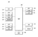
도 2은 본 발명의 일 실시 예에 따른 주행로봇(100)의 구성을 설명하기 위한 도면이다. 본 발명의 일 실시예에 따른 주행로봇(100)을 도시한 도 3 내지 5를 함께 참고하여 설명하기로 한다.FIG. 2 is a drawing for explaining the configuration of a driving robot (100) according to an embodiment of the present invention. The description will be made with reference to FIGS. 3 to 5, which illustrate a driving robot (100) according to an embodiment of the present invention.
도 2을 참고하면, 주행로봇(100)은 보관 영역(50)을 포함하는 바디(Body)를 포함할 수 있으며, 후술하는 구성들이 바디(Body)에 포함될 수 있다. 주행로봇(100)은 통신부(110), 입력부(120), 센서부(140), 출력부(150), 메모리(185), 휠 구동부(170), 제어부(180) 및 전원공급부(190)를 포함할 수 있다. 도 2에 도시된 구성요소들은 주행로봇(100)을 구현하는데 있어서 필수적인 것은 아니어서, 본 명세서 상에서 설명되는 주행로봇(100)은 위에서 열거된 구성요소들 보다 많거나, 또는 적은 구성요소들을 가질 수 있다.Referring to FIG. 2, the driving robot (100) may include a body including a storage area (50), and the components described below may be included in the body. The driving robot (100) may include a communication unit (110), an input unit (120), a sensor unit (140), an output unit (150), a memory (185), a wheel drive unit (170), a control unit (180), and a power supply unit (190). The components illustrated in FIG. 2 are not essential for implementing the driving robot (100), and thus the driving robot (100) described in this specification may have more or fewer components than the components listed above.
통신부(110, Transceiver)는 로봇 관제 시스템(200)과 통신할 수 있는 유무선의 통신 모듈을 포함할 수 있다.The communication unit (110, Transceiver) may include a wired or wireless communication module capable of communicating with the robot control system (200).
선택적 실시 예로 상기 통신부(110)는 GSM(Global System for Mobile communication), CDMA(Code Division Multi Access), LTE(Long Term Evolution), 5G, WLAN(Wireless LAN), Wi-Fi(Wireless-Fidelity), 블루투스(Bluetooth), RFID(Radio Frequency Identification), 적외선 통신(Infrared Data Association;IrDA), ZigBee, NFC(Near Field Communication) 통신에 관한 모듈을 탑재할 수 있다.As an optional embodiment, the communication unit (110) may be equipped with modules related to GSM (Global System for Mobile communication), CDMA (Code Division Multi Access), LTE (Long Term Evolution), 5G, WLAN (Wireless LAN), Wi-Fi (Wireless-Fidelity), Bluetooth, RFID (Radio Frequency Identification), Infrared Data Association (IrDA), ZigBee, and NFC (Near Field Communication) communications.
입력부(120)는 사용자로부터 정보를 입력 받기 위한 사용자 입력부(122)를 포함할 수 있다. 선택적 실시 예로 입력부(120)는 영상 신호 입력을 위한 카메라(121), 오디오 신호를 수신하기 위한 마이크로폰(123, "이하, 마이크로 칭함")을 포함할 수 있다. 여기서, 카메라(121)나 마이크(123)를 센서로 취급하여, 카메라(121)나 마이크(123)에서 획득한 신호를 센싱 데이터 또는 센서 정보라고 할 수도 있다.The input unit (120) may include a user input unit (122) for receiving information from a user. As an optional embodiment, the input unit (120) may include a camera (121) for inputting a video signal and a microphone (123, “hereinafter, referred to as a microphone”) for receiving an audio signal. Here, the camera (121) or the microphone (123) may be treated as a sensor, and a signal obtained from the camera (121) or the microphone (123) may be referred to as sensing data or sensor information.
입력부(120)는 모델 학습을 위한 학습 데이터 및 학습 모델을 이용하여 출력을 획득할 때, 사용될 입력 데이터 등을 획득할 수 있다. 입력부(120)는 가공되지 않은 입력 데이터를 획득할 수도 있으며, 이 경우 제어부(180)는 입력 데이터에 대하여 전처리로써 입력 특징점(input feature)을 추출할 수 있다.The input unit (120) can obtain input data to be used when obtaining output using learning data and a learning model for model learning. The input unit (120) can also obtain unprocessed input data, and in this case, the control unit (180) can extract input features as preprocessing for the input data.
카메라(121)는 전방의 장애물을 감지하기 위해 전방에 위치하며, 도 3에 도시된 바와 같이 각도가 상이하게 복수 개가 배치될 수 있다. 전방을 넓게 인식하는 카메라와 바닥을 촬영하는 카메라와 같이 촬영 방향이 상이한 복수개의 카메라(121)를 구비할 수 있다.The camera (121) is positioned in front to detect obstacles in front, and may be positioned at different angles as shown in Fig. 3. A plurality of cameras (121) with different shooting directions, such as a camera that recognizes the front widely and a camera that photographs the floor, may be provided.
또는 상이한 기능을 가지는 카메라를 구비할 수 있다. 예를 들어 광각카메라, 적외선 카메라 등을 구비할 수 있다. 카메라는 센서부(140)로서 주변의 사물을 감지하는 역할을 할 수 있다.Or, it may be equipped with a camera having different functions. For example, it may be equipped with a wide-angle camera, an infrared camera, etc. The camera may serve as a sensor unit (140) to detect surrounding objects.
사용자 입력부(122)는 버튼이나 디스플레이(151)와 중첩된 터치패널을 구비할 수 있다. 또는 원격으로 통신부(110)를 통해 사용자 명령을 입력할 수도 있으며, 이 경우 사용자 입력부(122)는 주행로봇(100)과 별도로 구비된 개인 컴퓨터(400)나 원격제어장치를 포함할 수 있다.The user input unit (122) may be equipped with a button or a touch panel overlapping the display (151). Alternatively, a user command may be input remotely through the communication unit (110). In this case, the user input unit (122) may include a personal computer (400) or remote control device separately equipped from the driving robot (100).
사용자 입력부(122)는 사용자 명령을 입력받는 방식을 모두 포함하므로 음성인식을 통해 사용자 명령을 인식할 수 있다. 즉 마이크(123)서 수집한 음성을 분석하여 사용자 명령을 추출하는 음성인식장치도 사용자 입력부(122)로서 역할을 할 수 있다.The user input unit (122) includes all methods for receiving user commands, so that user commands can be recognized through voice recognition. In other words, a voice recognition device that analyzes voice collected from a microphone (123) and extracts user commands can also function as the user input unit (122).
입력부(120)는 물품 정보 입력부를 포함할 수 있는데, 상기 물품 정보 입력부는 물품의 사이즈 정보, 무게 정보, 목적지 정보, 운송 의뢰자에 대한 정보 등을 입력받을 수 있다. 이때, 상기 물품 정보 입력부는 코드 리더를 포함할 수 있다.The input unit (120) may include a product information input unit, and the product information input unit may receive size information of the product, weight information, destination information, information about the transport requester, etc. In this case, the product information input unit may include a code reader.
센서부(140)는 다양한 센서들을 이용하여 주행로봇(100)의 내부 정보, 주행로봇(100)의 주변 환경 정보 및 사용자 정보 중 적어도 하나를 획득할 수 있다.The sensor unit (140) can obtain at least one of internal information of the driving robot (100), information about the surrounding environment of the driving robot (100), and user information using various sensors.
이때, 센서부(140)는 자율주행을 위해 주변을 인식하기 위한 다양한 종류의 센서를 포함할 수 있다. 대표적으로 거리 감지 센서 또는 근접센서(141)와 라이다(142)를 들 수 있다.At this time, the sensor unit (140) may include various types of sensors for recognizing the surroundings for autonomous driving. Representative examples include a distance detection sensor or proximity sensor (141) and a lidar (142).
근접센서(141)는 사출한 초음파가 돌아오는 시간을 기초로 근처의 사물을 인식하고 사물과의 거리를 판단하는 초음파 센서를 포함할 수 있다. 근접센서는 둘레를 따라 복수개를 구비할 수 있으며, 상측의 장애물을 감지하기 위해 상측에도 구비할 수 있다.The proximity sensor (141) may include an ultrasonic sensor that recognizes nearby objects and determines the distance to the objects based on the time it takes for the emitted ultrasonic waves to return. A plurality of proximity sensors may be provided along the perimeter, and one may also be provided on the upper side to detect obstacles on the upper side.
라이다(Lidar, 142)는 레이저 펄스를 발사하고 그 빛이 주위의 대상물체에 반사되어 돌아오는 것을 받아 주변의 모습을 정밀하게 그려내는 장치이다. 레이다와 같이 그 원리는 유사하나 사용하는 전자기파가 달라 이용 기술과 활용범위가 상이하다.Lidar (142) is a device that precisely draws the surroundings by firing laser pulses and receiving the light that is reflected from surrounding objects. Its principle is similar to radar, but the electromagnetic waves used are different, so the technology and scope of use are different.
레이저는 600~1000nm 파장의 빛을 사용하기 때문에 사람의 시력을 손상시킬 수 있다. 라이다(342)는 이보다 더 긴 파장을 이용하며, 대상 물체까지의 거리뿐 아니라 움직이는 속도와 방향, 온도, 주변의 대기 물질 분석 및 농도 측정 등에 쓰인다.Lasers can damage human eyesight because they use light with a wavelength of 600 to 1000 nm. Lidar (342) uses a longer wavelength and is used to measure not only the distance to a target object, but also the speed and direction of its movement, temperature, and analysis and concentration of surrounding atmospheric substances.
그 외에 센서부(140)는 조도 센서, 가속도 센서, 자기 센서, 자이로 센서, 관성 센서, RGB 센서, 적외선 센서, 지문 인식 센서, 초음파 센서, 광 센서, 홀센서 등을 포함할 수 있다.In addition, the sensor unit (140) may include a light sensor, an acceleration sensor, a magnetic sensor, a gyro sensor, an inertial sensor, an RGB sensor, an infrared sensor, a fingerprint recognition sensor, an ultrasonic sensor, a light sensor, a Hall sensor, etc.
출력부(150)는 시각, 청각 또는 촉각 등과 관련된 출력을 발생시킬 수 있는데, 출력부(150)는 시각 정보를 출력하는 광 출력부, 디스플레이 (151) 등을 포함할 수 있으며, 청각 정보를 출력하는 스피커 (152), 비가청 주파수에 속하는 초음파 신호를 출력하는 초음파 출력부 등을 포함할 수 있고, 촉각 정보를 출력하는 햅틱 모듈을 포함할 수 있다.The output unit (150) can generate output related to vision, hearing, or tactile sensations, and the output unit (150) can include an optical output unit that outputs visual information, a display (151), etc., a speaker (152) that outputs auditory information, an ultrasonic output unit that outputs ultrasonic signals belonging to an inaudible frequency, etc., and can include a haptic module that outputs tactile information.
메모리(185)는 주행로봇(100)의 다양한 기능을 지원하는 데이터를 저장한다. 메모리(185)는 주행로봇(100)에서 구동되는 다수의 응용 프로그램(application program 또는 애플리케이션(application)), 주행로봇(100)의 동작을 위한 데이터들, 명령어들을 저장할 수 있다.The memory (185) stores data that supports various functions of the driving robot (100). The memory (185) can store a number of application programs (or applications) run by the driving robot (100), data for the operation of the driving robot (100), and commands.
아울러, 메모리(185)는 인공 지능, 머신 러닝, 인공 신경망을 이용하여 연산을 수행하는데 필요한 정보를 저장할 수 있다. 메모리(185)는 심층 신경망 모델을 저장할 수 있다. 상기 심층 신경망 모델은 학습 데이터가 아닌 새로운 입력 데이터에 대하여 결과 값을 추론해 내는데 사용될 수 있고, 추론된 값은 어떠한 동작을 수행하기 위한 판단의 기초로 이용될 수 있다.In addition, the memory (185) can store information necessary for performing operations using artificial intelligence, machine learning, and artificial neural networks. The memory (185) can store a deep neural network model. The deep neural network model can be used to infer a result value for new input data other than learning data, and the inferred value can be used as a basis for judgment for performing a certain operation.
전원공급부(190)는 프로세서(190)의 제어 하에서, 외부의 전원, 내부의 전원을 인가 받아 주행로봇(100)의 각 구성요소들에 전원을 공급한다. 이러한 전원공급부(190)는 배터리(191)를 포함하며, 상기 배터리(191)는 내장형 배터리 또는 교체가능한 형태의 배터리가 될 수 있다. 상기 배터리는 유선 또는 무선 충전 방식으로 충전될 수 있는데, 무선 충전 방식은 자기 유도 방식 또는 자기 공진 방식을 포함할 수 있다.The power supply unit (190) receives external power and internal power under the control of the processor (190) and supplies power to each component of the driving robot (100). The power supply unit (190) includes a battery (191), and the battery (191) may be a built-in battery or a replaceable battery. The battery may be charged by a wired or wireless charging method, and the wireless charging method may include a magnetic induction method or a magnetic resonance method.
주행부(170)는 주행로봇(100)을 이동시키기 위한 수단으로서, 휠 또는 레그를 포함할 수 있으며 이를 제어하는 휠 구동부 및 레그 구동부를 포함할 수 있다. 휠 구동부 바닥면에 구비된 복수의 휠을 제어하여 바디(Body)를 포함하는 주행로봇(100)을 이동시킬 수 있다. 휠은 빠른 주행을 위한 메인휠(171)과 방향전환을 위한 캐스터(173) 그리고 주행 중 적재된 물품(L)이 떨어지지 않도록 안정적인 주행을 위한 보조 캐스터 등을 포함할 수 있다.The driving unit (170) is a means for moving the driving robot (100), and may include wheels or legs, and may include a wheel driving unit and a leg driving unit that control them. A plurality of wheels provided on the bottom surface of the wheel driving unit can be controlled to move the driving robot (100) including the body. The wheels may include a main wheel (171) for fast driving, a caster (173) for changing direction, and an auxiliary caster for stable driving so that the loaded item (L) does not fall during driving.
레그 구동부(미도시)는 제어부(180)의 제어에 따라 복수의 레그를 제어하여 바디를 이동시킬 수 있다. 복수의 레그는 주행로봇(100)이 걷거나 뛸 수 있도록 형성된 구성에 해당될 수 있다. 복수의 레그는 4 개로 구현될 수 있으나, 실시 예가 이에 국한되는 것은 아니다. 복수의 레그는 바디에 결합되어 일체형으로 형성될 수 있으며, 바디에 탈부착 형태로 구현될 수 있다.The leg drive unit (not shown) can control a plurality of legs to move the body according to the control of the control unit (180). The plurality of legs may correspond to a configuration formed so that the driving robot (100) can walk or run. The plurality of legs may be implemented as four, but the embodiment is not limited thereto. The plurality of legs may be formed as an integral body by being combined with the body, and may be implemented in a form that is attachable to and detachable from the body.
주행로봇(100)은 휠 구동부 및/또는 레그 구동부 중 적어도 하나를 구비하는 주행부(170)를 통해 바디를 이동시킬 수 있다. 다만, 본 명세서 상에서는 휠 구동부가 이동 로봇(100)에 탑재된 예를 주로 설명한다.A driving robot (100) can move its body through a driving unit (170) having at least one of a wheel driving unit and/or a leg driving unit. However, in this specification, an example in which a wheel driving unit is mounted on a mobile robot (100) is mainly described.
제어부(180)는 주행로봇(100)의 구성들을 컨트롤하는 모듈이다. 상기 제어부(180)는 프로그램 내에 포함된 코드 또는 명령으로 표현된 기능을 수행하기 위해 물리적으로 구조화된 회로를 갖는, 하드웨어에 내장된 데이터 처리 장치를 의미할 수 있다. 이와 같이 하드웨어에 내장된 데이터 처리 장치의 일 예로써, 마이크로프로세서(microprocessor), 중앙처리장치(central processing unit: CPU), 프로세서 코어(processor core), 멀티프로세서(multiprocessor), ASIC(application-specific integrated circuit), FPGA(field programmable gate array) 등의 처리 장치를 망라할 수 있으나, 본 발명의 범위가 이에 한정되는 것은 아니다.The control unit (180) is a module that controls the configurations of the driving robot (100). The control unit (180) may mean a data processing device built into hardware that has a physically structured circuit to perform a function expressed by a code or command included in a program. As an example of a data processing device built into hardware, a microprocessor, a central processing unit (CPU), a processor core, a multiprocessor, an application-specific integrated circuit (ASIC), a field programmable gate array (FPGA), and the like may be included, but the scope of the present invention is not limited thereto.
주행로봇(100)은 본체에 적재영역(50)을 포함하며, 적재영역(50)은 떨어지지 않도록 이를 보호하는 측벽 또는 커버(10)를 포함할 수 있다. 도 3을 참고하면 커버(10)를 구비한 것으로 도시하고 있으나, 상면을 생략하고 측벽만 구비한 형태도 가능하다.The driving robot (100) includes a loading area (50) in the main body, and the loading area (50) may include a side wall or cover (10) to protect it from falling. Referring to Fig. 3, it is illustrated as having a cover (10), but a form in which only a side wall is provided while omitting the upper surface is also possible.
적재영역(50)은 도면상에서 별도의 층구별이 없으나, 복수개의 층으로 구성되어 층별로 나누어 복수개의 물품을 적재 가능하며 하부의 물품(L)을 하차한 이후에 상부의 물품을 하부층으로 이동시켜 추가적으로 물품을 하차할 수 있다.The loading area (50) does not have a separate floor division in the drawing, but is composed of multiple floors and can load multiple items by dividing them into each floor. After unloading the lower item (L), the upper item can be moved to the lower floor to unload additional items.
제어부(180)는 적재영역(50)에 배치될 물품(L)의 개수 정보, 무게 정보, 사이즈 정보, 배송 순서 정보, 보안 등급 정보 중 적어도 하나를 수집할 수 있다. 가령, 제어부(180)는 입력부(120)를 통해 상기 정보들을 수집할 수 있다. 상기 입력부(120)의 입력은 디스플레이 상의 터치 입력도 포함할 수 있다.The control unit (180) can collect at least one of the number of items (L) to be placed in the loading area (50), weight information, size information, delivery order information, and security level information. For example, the control unit (180) can collect the above information through the input unit (120). The input of the input unit (120) can also include a touch input on the display.
제어부(180)는 수집된 상기 정보들에 기초하여, 적재영역(50)에 적재된 물품(L)의 정보를 통신부(110)를 통해 이동 단말(도 1의 200)으로 전송할 수 있다.Based on the collected information, the control unit (180) can transmit information on goods (L) loaded in the loading area (50) to the mobile terminal (200 in FIG. 1) through the communication unit (110).
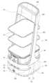
도 3은 본 발명의 일 실시 예에 따른 주행로봇(100)의 전면 사시도이고, 도 4는 본 발명의 일 실시 예에 따른 주행로봇(100)의 후면 사시도이다.FIG. 3 is a front perspective view of a driving robot (100) according to an embodiment of the present invention, and FIG. 4 is a rear perspective view of a driving robot (100) according to an embodiment of the present invention.
본 발명의 주행로봇(100)의 주행부(170)와 기판모듈(181), 배터리(191) 등을 구비한 하측부(101)는 서빙로봇, 운송로봇이나 살균로봇 등 주행기능을 구비한 로봇에 모두 적용할 수 있다.The lower part (101) of the driving robot (100) of the present invention, which is equipped with a driving part (170), a substrate module (181), a battery (191), etc., can be applied to all robots equipped with a driving function, such as a serving robot, a transport robot, or a sterilization robot.
다만, 설명의 편의를 위해 도 3 및 도 4에 도시된 상부에 트레이 모듈(131)을 구비한 서빙로봇을 기준으로 설명하나 다른 형태의 주행로봇(100)에도 적용 가능하다.However, for convenience of explanation, the description is based on a serving robot equipped with a tray module (131) on the upper side as shown in FIGS. 3 and 4, but it can also be applied to other types of driving robots (100).
도 3을 참조하면 하측부(101)와 상측부(102)로 구분될 수 있다. 하측부(101)는 전자부품을 실장하기 위한 프레임 조립체(104)와 프레임 조립체(104)의 하부에 위치하며 주행로봇(100)의 이동을 담당하는 주행부(170)를 포함할 수 있다.Referring to Fig. 3, it can be divided into a lower part (101) and an upper part (102). The lower part (101) can include a frame assembly (104) for mounting electronic components and a driving part (170) located at the lower part of the frame assembly (104) and responsible for the movement of the driving robot (100).
프레임 조립체(104)에 실장되는 전장부품은 주행로봇(100)의 제어를 담당하는 제어부로서 복수개의 IC와 기판의 집합체로 구성된 기판모듈(181)이 실장된다. 또한, 전원을 공급하는 배터리(191), 주행을 보조하기 위한 각종 센서부 및 카메라(121) 등이 실장될 수 있다. 출력을 위한 스피커(152)나 LED램프 등이 실장될 수 있다.The electrical components mounted on the frame assembly (104) are a control unit that controls the driving robot (100), and a board module (181) composed of a combination of multiple ICs and a board is mounted. In addition, a battery (191) that supplies power, various sensor units for assisting driving, and a camera (121), etc. can be mounted. A speaker (152) or an LED lamp for output, etc. can be mounted.
디스플레이(151)는 터치입력 및 시각적 출력을 담당할 수 있으며 터치입력 시 손으로 입력을 수행하고 시각적 출력은 눈으로 인지를 하기 때문에 사용자의 키 높이를 고려하여 상측부(102)에 배치한다.The display (151) can handle touch input and visual output. Since touch input is performed by hand and visual output is recognized by eye, it is placed on the upper part (102) considering the user's height.
디스플레이(151)를 제외한 대부분의 전장부품은 하측부(101)에 위치할 수 있다. 하측부(101)는 외관을 형성하는 하부 하우징(1011, 1012, 1013, 1014, 1015)을 포함하고, 하부 구조(101)는 원통형이나 사각형형상의 박스형상을 가질 수 있다.Most of the electrical components except for the display (151) can be located on the lower part (101). The lower part (101) includes a lower housing (1011, 1012, 1013, 1014, 1015) forming the exterior, and the lower structure (101) can have a cylindrical or rectangular box shape.
도 3에 도시된 바와 같이 하부 구조(101)가 너비에 비해 높이가 낮은 형태로 구성하여 주행로봇(100) 주행 시 안정성을 확보할 수 있다. 상측부(102)인 트레이 모듈(131) 상에 그릇이나 물품을 안착시 무게중심이 상부로 이동할 수 있으므로, 무게중심을 낮추기 위해 하측부(101)에 대부분의 전자부품을 배치할 수 있다.As shown in Fig. 3, the lower structure (101) is configured to have a lower height than its width to ensure stability when the driving robot (100) is driven. When a bowl or an item is placed on the tray module (131) of the upper part (102), the center of gravity can move upward, so that most of the electronic components can be placed on the lower part (101) to lower the center of gravity.
하측부(101)의 프레임 조립체(104)를 금속재질로 구성하여 하측부(101)의 무게를 상부대비 크게 구성할 수 있다. 하측부(101)의 무게를 더 확보하기 위해 하측부(101)에 무게추를 추가적으로 구비할 수 있다.The frame assembly (104) of the lower part (101) can be made of metal material so that the weight of the lower part (101) is greater than that of the upper part. In order to secure more weight of the lower part (101), a weight can be additionally provided on the lower part (101).
하측부(101)의 전방은 라이다(142), 카메라(121), 근접센서 등이 배치될 수 있다. 라이다(142)는 감지 각도가 넓기 때문에 도 3에 도시된 바와 같이 전면에서 후방으로 인입된 홈부(1016)에 안착될 수 있다. 홈부(1016)는 수평방향으로 길게 이어진 형태를 가질 수 있으며 측방향으로 약 1/3정도까지 배면 방향으로 인입된 형태를 가질 수 있다.The front of the lower part (101) may be equipped with a lidar (142), a camera (121), a proximity sensor, etc. Since the lidar (142) has a wide detection angle, it may be installed in a groove (1016) that is introduced from the front to the rear as shown in Fig. 3. The groove (1016) may have a long horizontal shape and may have a shape that is introduced in the rear direction by about 1/3 in the side direction.
홈부(1016)의 내측에 위치하는 라이다(142)는 상측에서 물이 쏟아지더라도 직접적으로 물이 유입되지 않아 침수에 의한 고장이 발생하는 것을 방지할 수 있다. 홈부(1016)에 라이다(142) 뿐만 아니라 스피커(152) 및 방열팬(187) 등의 외측으로 노출되어야 하는 전자부품을 배치하여 내구성을 보다 확보할 수 있다.The lidar (142) located on the inside of the home section (1016) can prevent water from directly flowing in even if water pours in from above, thereby preventing malfunctions due to submersion. In addition to the lidar (142), electronic components that must be exposed to the outside, such as the speaker (152) and the heat dissipation fan (187), can be placed on the home section (1016) to further secure durability.
카메라(121)는 하측부(101)의 상면 전방에 위치할 수 있다. 주행로봇(101)은 각도가 상이하게 배치된 복수 개의 카메라를 구비하여 넓은 범위에서 물체를 인식할 수 있다. 즉 카메라(121)는 전방을 향하는 제1 카메라(121)와 상측으로 비스듬히 기울어진 제2 카메라(121) 그리고 하측으로 비스듬하게 기울어진 제3 카메라(121) 중 적어도 하나 이상을 구비할 수 있다.The camera (121) may be positioned in front of the upper surface of the lower part (101). The driving robot (101) may be equipped with a plurality of cameras arranged at different angles to recognize objects in a wide range. That is, the camera (121) may be equipped with at least one of a first camera (121) facing forward, a second camera (121) tilted upward, and a third camera (121) tilted downward.
하측부(101)의 아래에 위치하는 주행부(170)는 복수개의 휠을 포함하며 보다 구체적으로 구동력을 제공하는 모터(1715)가 포함된 메인휠(171)과 방향을 제어하면서 주행의 안전성을 제고하는 캐스터(173)를 포함할 수 있다.The driving part (170) located below the lower part (101) includes a plurality of wheels, and more specifically, may include a main wheel (171) including a motor (1715) that provides driving force, and a caster (173) that controls direction and improves driving safety.
메인휠(171)은 측방향으로 연장된 모터의 축을 중심으로 회전력을 전달받아 주행하고, 캐스터 휠(1731)이 연결된 캐스터 바디(1732)가 수직방향으로 연장된 샤프트(1736)를 중심으로 회전 가능하게 하측부(101)에 결합할 수 있다.The main wheel (171) receives rotational power and drives around the axis of the motor extended laterally, and a caster body (1732) to which a caster wheel (1731) is connected can be connected to the lower part (101) so as to be rotatable around a shaft (1736) extended in the vertical direction.
상측부(101)는 하부 하우징의 상측으로 연장된 트레이 프레임(1055)과 트레이 프레임(1055)에 결합된 트레이 모듈(131)을 포함한다. 트레이 모듈(131)을 안정적으로 지지하기 위해 한 쌍의 트레이 프레임(1055)이 좌우 양측에서 상부를 향해 연장될 수 있으며 트레이 모듈(131)은 양측에서 트레이 프레임(1055) 상에 결합된 트레이 홀더(133)에 의해 지지될 수 있다.The upper part (101) includes a tray frame (1055) extending upwardly from the lower housing and a tray module (131) coupled to the tray frame (1055). In order to stably support the tray module (131), a pair of tray frames (1055) may extend upwardly on both left and right sides, and the tray module (131) may be supported by tray holders (133) coupled on the tray frames (1055) on both sides.
도 3에 도시된 바와 같이 트레이 모듈(131)은 복수개 포함할 수 있다. 트레이 프레임(1055)은 비스듬하게 배면 방향으로 기울어진 형태를 이루며, 트레이 프레임(1055)의 전방 공간을 비교적 넓게 확보하여 그릇을 넣고 빼는데 보다 용이하다.As shown in Fig. 3, a plurality of tray modules (131) may be included. The tray frame (1055) is formed in a shape that is inclined obliquely toward the rear, and the front space of the tray frame (1055) is secured relatively wide, making it easier to put in and take out dishes.
한 쌍의 트레이 프레임(1055) 상단은 서로 연결되는 헤드 프레임(1021)을 포함할 수 있다. 헤드 프레임(1021)의 전방에 전술한 디스플레이(151)가 위치할 수 있다. 디스플레이(151) 이외의 전자부품은 헤드 프레임(1021)에 위치하지 않아 도 5에 도시된 바와 같이 상부바스켓(1025)을 구비할 수 있다.The upper portion of a pair of tray frames (1055) may include a head frame (1021) that is connected to each other. The display (151) described above may be positioned in front of the head frame (1021). Electronic components other than the display (151) are not positioned in the head frame (1021), so that an upper basket (1025) may be provided as illustrated in FIG. 5.
상부바스켓(1025)에 물티슈나 휴지와 같은 비품을 배치하여 고객이 손쉽게 가져갈 수 있으며 음식국물 등에 의해 오염되지 않는 부분이어서 위생적으로 관리 가능하다.Supplies such as wet tissues and toilet paper are placed in the upper basket (1025) so that customers can easily take them, and they can be hygienically managed as they are not contaminated with food broth, etc.
하부 하우징의 상면에 안착되는 슬라이드 바스켓(106)을 더 구비할 수 있다. 슬라이드 바스켓(106)은 하부 하우징의 상면에 의해 지지되므로 빈 그릇과 같이 비교적 무거운 물건을 수납할 수 있다. 깊이가 있어 국물등이 흐르지 않고, 슬라이드 방식으로 주행로봇(100)으로부터 분리가능하므로 물건의 이동 및 세척이 용이하다.A slide basket (106) that is mounted on the upper surface of the lower housing may be additionally provided. The slide basket (106) is supported by the upper surface of the lower housing, so it can store relatively heavy objects such as empty bowls. It has a depth so that liquids and the like do not spill, and it can be separated from the driving robot (100) in a sliding manner, so it is easy to move and wash objects.
슬라이드 바스켓(106)은 트레이 모듈(131)과 하부 하우징의 상면 사이에 위치할 수 있으며 도면상 트레이 모듈(131)은 슬라이드 바스켓(106) 바로 위에 위치하는 것으로 도시되어 있으나, 슬라이드 바스켓(106)은 트레이 모듈(131)에서 소정거리 이격된 위치에 배치될 수 있다.The slide basket (106) can be positioned between the tray module (131) and the upper surface of the lower housing, and although the tray module (131) is depicted as being positioned directly above the slide basket (106) in the drawing, the slide basket (106) can be positioned at a predetermined distance from the tray module (131).
슬라이드 바스켓(106)의 좌우방향으로 트레이 프레임(1055)이 위치하고 전방에는 카메라(121)가 실장되는 카메라(121) 케이스가 위치하므로 슬라이드 바스켓(106)은 배면 방방향으로만 인출가능하며 다른 방향으로 쉽게 인출되지 않아 안정적으로 주행 가능하다.Since the tray frame (1055) is positioned in the left and right directions of the slide basket (106) and the camera (121) case in which the camera (121) is mounted is positioned in the front, the slide basket (106) can only be pulled out in the rear direction and is not easily pulled out in other directions, enabling stable driving.
슬라이드 바스켓(106)을 배면 방향으로 잡아당기기 용이하도록 배면 방향에 손잡이를 구비할 수 있다.A handle may be provided on the rear side to facilitate pulling the slide basket (106) in the rear direction.
도 5는 본 발명의 일 실시 예에 따른 주행로봇(100)의 분해 사시도이다. 상측부(101)는 하측부(101)와 분리 가능하며 트레이 프레임(1055)의 외관을 형성하는 측부 케이스를 분리하면 하측부(101)에서 상측으로 연장된 연결 프레임(1045)과 트레이 프레임(1055)의 체결부가 노출될 수 있다. 연결 프레임(1045)과 트레이 프레임(1055)을 체결하는 스크류를 제거하여 도 5와 같이 상측부(101)를 하측부(101)에서 분리할 수 있다.Fig. 5 is an exploded perspective view of a driving robot (100) according to one embodiment of the present invention. The upper part (101) is separable from the lower part (101), and when the side case forming the outer appearance of the tray frame (1055) is separated, the connecting frame (1045) extending upward from the lower part (101) and the fastening part of the tray frame (1055) can be exposed. By removing the screw that fastens the connecting frame (1045) and the tray frame (1055), the upper part (101) can be separated from the lower part (101) as shown in Fig. 5.
상측부(101)의 전자부품은 디스플레이(151) 및 트레이 모듈(131)의 무게를 감지하는 로드셀(135)이 있으며 상기 전자부품은 트레이 프레임(1055)의 연장방향을 따라 케이블이 연결되어 하측부(101)에 위치하는 제어부인 기판모듈(181)과 연결될 수 있다.The electronic component of the upper part (101) has a load cell (135) that detects the weight of the display (151) and the tray module (131), and the electronic component can be connected to the control part, the substrate module (181), located at the lower part (101) by a cable connected along the extension direction of the tray frame (1055).
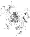
도 6은 본 발명의 일 실시 예에 따른 주행로봇(100)의 하측부(101)의 분해사시도이다. 하측부(101)는 외관을 형성하는 하부 하우징은 전면에 위치하는 제1 케이스(1011)와 후면에 위치하는 제2 케이스(1012), 상면을 형성하는 제3 케이스(1013)를 포함할 수 있다.Figure 6 is an exploded perspective view of the lower part (101) of a driving robot (100) according to one embodiment of the present invention. The lower part (101) may include a lower housing forming an exterior, a first case (1011) positioned at the front, a second case (1012) positioned at the rear, and a third case (1013) forming an upper surface.
제1 케이스(1011), 제2 케이스(1012) 및 제3 케이스(1013)으로 둘러싸인 전장부에 프레임 조립체(104), 주행부(170), 기판모듈(181) 및 배터리(191)가 실장될 수 있다.A frame assembly (104), a driving unit (170), a substrate module (181), and a battery (191) can be mounted in a front section surrounded by a first case (1011), a second case (1012), and a third case (1013).
하측부(101)의 전방에서 돌출된 카메라 케이스는 제1 케이스(1011) 또는 제3 케이스(1013)와 독립된 별도의 케이스로 구비할 수도 있고, 도 6에 도시된 바와 같이, 제3 케이스(1013)의 일부분이 돌출되어 카메라(121) 케이스를 구성할 수 있다. 카메라(121)는 전방은 빛을 투과하는 투명한 글래스를 구비하므로 도 6에 도시된 바와 같이 카메라 커버(1014)를 별도로 구비할 수 있다.The camera case protruding from the front of the lower part (101) may be provided as a separate case independent of the first case (1011) or the third case (1013), or as shown in FIG. 6, a part of the third case (1013) may protrude to form the camera (121) case. Since the front of the camera (121) is provided with transparent glass that transmits light, a camera cover (1014) may be provided separately as shown in FIG. 6.
도 7은 본 발명의 일 실시 예에 따른 주행로봇(100)의 트레이 모듈(131)과 그 체결구조를 도시한 분해사시도이다. 도 3에 도시된 바와 같이 본 발명의 주행로봇(100)은 상부에 그릇을 운반하기 위해 복수개의 트레이 모듈(131)을 구비할 수 있다.Fig. 7 is an exploded perspective view showing a tray module (131) of a driving robot (100) and its fastening structure according to one embodiment of the present invention. As shown in Fig. 3, the driving robot (100) of the present invention may be equipped with a plurality of tray modules (131) to transport dishes on the upper side.
종래의 서빙을 위한 주행로봇(100)은 트레이 모듈(131)의 높이가 고정되어 있어 높이가 높은 그릇은 운반이 어려운 한계가 있었다.The conventional driving robot (100) for serving had a limitation in that it was difficult to transport tall dishes because the height of the tray module (131) was fixed.
또한, 트레이 모듈(131) 상에 위치한 그릇의 유무를 감지하거나 그릇이 운반 중에 넘어지는 등의 상황을 로봇이 감지하기 어려워 그릇이 넘어지거나 떨어지는 경우에도 주행을 계속하는 문제 등이 발생하였다.In addition, there was a problem in that the robot had difficulty detecting the presence or absence of a bowl located on the tray module (131) or detecting situations in which a bowl fell during transport, and thus continued to drive even when the bowl fell or fell.
따라서, 트레이 모듈(131)의 위치를 다양하게 조절할 수 있으면서도 안정적으로 주행 가능하며, 동시에 트레이 모듈(131) 상에 놓여진 그릇의 무게를 감지할 수 있는 트레이 모듈(131)에 대한 니즈가 있다.Accordingly, there is a need for a tray module (131) that can operate stably while having the position of the tray module (131) adjusted in various ways, and at the same time can detect the weight of a bowl placed on the tray module (131).
트레이 모듈(131)상의 무게를 감지하기 위해서는 무게를 측정하는 로드셀(135)이 필요하나, 로드셀(135)은 제어부와 연결되므로 이를 트레이 프레임(1055)에서 탈착하기 어려워 트레이 모듈(131)의 위치 변경시 로드셀(135)을 분리해야하는 번거로움이 있다.In order to detect the weight on the tray module (131), a load cell (135) that measures the weight is required. However, since the load cell (135) is connected to the control unit, it is difficult to detach it from the tray frame (1055), so there is the inconvenience of having to detach the load cell (135) when changing the position of the tray module (131).
본 발명은 상기 두가지 니즈를 모두 충족할 수 있도록 로드셀(135)은 고정된 상태에서 트레이 모듈(131)의 위치를 변경할 수 있는 트레이 고정구조를 포함한 주행로봇(100) 대해 설명하도록 한다.The present invention describes a driving robot (100) including a tray fixing structure that can change the position of a tray module (131) while the load cell (135) is fixed so as to satisfy both of the above needs.
도 7에 도시된 바와 같이 본 발명의 트레이 모듈(131)은 위치를 가변할 수 있도록 트레이 프레임(1055)에서 분리 가능하며, 트레이 프레임(1055)에서 트레이 모듈(131)을 지지하기 위한 트레이 홀더(133)의 위치를 변화시켜 트레이 모듈(131)의 위치를 조절할 수 있다.As illustrated in FIG. 7, the tray module (131) of the present invention is detachable from the tray frame (1055) so that its position can be changed, and the position of the tray module (131) can be adjusted by changing the position of the tray holder (133) for supporting the tray module (131) in the tray frame (1055).
트레이 프레임(1055)은 트레이 홀더(133)가 삽입되기 위한 체결홀(1058)을 구비할 수 있다. 체결홀(1058)의 바깥쪽에서 내측 방향으로 트레이 홀더(133)를 삽입하여 트레이 프레임(1055)의 내측 방향으로 트레이 모듈(131)의 하부를 지지하는 트레이 홀더(133)의 지지부(1331)가 돌출될 수 있다.The tray frame (1055) may be provided with a fastening hole (1058) into which a tray holder (133) is inserted. By inserting the tray holder (133) from the outside to the inside of the fastening hole (1058), a support portion (1331) of the tray holder (133) that supports the lower portion of the tray module (131) in the inside of the tray frame (1055) may protrude.
트레이 홀더(133)와 체결되는 트레이 바(132)가 트레이 모듈(131)의 좌우 양측에 위치할 수 있으며, 트레이 바(132)는 트레이 모듈(131)의 강성을 보강하고 트레이 모듈(131)의 무게가 트레이 홀더(133)에 전달되어 트레이 모듈(131)을 안정적으로 지지하는 역할을 한다.A tray bar (132) connected to a tray holder (133) can be positioned on both the left and right sides of the tray module (131). The tray bar (132) reinforces the rigidity of the tray module (131) and transfers the weight of the tray module (131) to the tray holder (133) to stably support the tray module (131).
도 3에 도시된 바와 같이 본 발명의 트레이 모듈(131)은 3개를 기본 적으로 배치할 수 있다. 추가적으로 더 많이 배치하기에는 간격이 너무 좁고 2개의 트레이 모듈(131)만 구비한 경우 트레이 개수가 너무 적다. 본 발명의 주행로봇(100)은 트레이 3개의 트레이 모듈(131)을 트레이 프레임(1055) 상에 결합하는 형태로 구성할 수 있다.As shown in Fig. 3, the tray modules (131) of the present invention can be basically arranged in three units. Additionally, the spacing is too narrow to arrange more, and if only two tray modules (131) are provided, the number of trays is too small. The driving robot (100) of the present invention can be configured in a form in which three tray modules (131) are combined on a tray frame (1055).
본 발명의 주행로봇(100)의 트레이 모듈(131)은 트레이 프레임(1055) 상에 위치를 가변할 수 있다. 다만, 하부에 위치하는 슬라이드 바스켓(106)의 상부에 위치하는 최하단의 트레이는 위치는 상측으로 굳이 이동할 필요 없다. 따라서, 상측에 위치하는 2개의 트레이 모듈(131)의 위치만 변화할 수 있도록 상측 트레이 모듈(131)에 대응되는 체결홀(1058)만 복수 개로 구성할 수 있다.The tray module (131) of the driving robot (100) of the present invention can change its position on the tray frame (1055). However, the lowermost tray located above the slide basket (106) located below does not necessarily need to move upward. Therefore, only the fastening holes (1058) corresponding to the upper tray modules (131) can be configured in multiple numbers so that only the positions of the two tray modules (131) located above can be changed.
본 실시예의 체결홀(1058)은 2개가 인접하고 다른 체결홀(1058)과 이격된 형태로 2개씩 세트로 구성될 수 있다. 도 7에 도시된 바와 같이 체결홀(1058)의 간격이 상이하게 구성할 수 있다.The fastening holes (1058) of the present embodiment may be configured in sets of two, with two adjacent ones and spaced apart from other fastening holes (1058). As shown in Fig. 7, the spacing between the fastening holes (1058) may be configured differently.
하나의 트레이 모듈(131)은 인접한 2개의 체결홀(1058) 중 하나를 이용하여 고정할 수 있으며, 이격된 체결홀(1058)은 서로 상이한 트레이 모듈(131)에 대응하는 체결홀(1058)이다.One tray module (131) can be secured using one of two adjacent fastening holes (1058), and the spaced fastening holes (1058) are fastening holes (1058) corresponding to different tray modules (131).
이용하지 않는 체결홀(1058)은 도 7에 도시된 바와 같이 체결홀 커버(1059)를 이용하여 트레이 프레임(1055)의 내부가 노출되지 않도록 덮을 수 있다.The unused fastening hole (1058) can be covered using a fastening hole cover (1059) as shown in Fig. 7 so that the interior of the tray frame (1055) is not exposed.
체결홀(1058)은 트레이 프레임(1055)에 수직방향으로 길게 연장된 타원형 또는 장방형을 가질 수 있다. 트레이 프레임(1055)이 도 7에 도시된 바와 같이, 상부가 비스듬하게 배면으로 기울어진 형태로 하측부(101)에 결합한 경우 체결홀(1058)의 길이 방향은 수평이 아니라 약간 기울어진 형태를 가질 수 있다.The fastening hole (1058) may have an oval or rectangular shape that is extended vertically to the tray frame (1055). When the tray frame (1055) is joined to the lower part (101) in a shape in which the upper part is inclined obliquely toward the back as shown in Fig. 7, the longitudinal direction of the fastening hole (1058) may have a slightly inclined shape rather than being horizontal.
체결홀(1058)의 길이방향이 수평으로 배치되려면 트레이 프레임(1055)에 대해 비스듬히 기울어진 형태로 구성해야 한하며, 그에 대응되는 로드셀(135) 및 브라켓(136, 137)도 비스듬히 기울어진 형태로 구성될 수 있다.In order for the longitudinal direction of the fastening hole (1058) to be arranged horizontally, it must be configured in a form that is inclined at an angle with respect to the tray frame (1055), and the corresponding load cell (135) and bracket (136, 137) can also be configured in a form that is inclined at an angle.
다만, 트레이 프레임(1055)의 우측과 좌측의 기울어진 방향이 상이하여 로드셀(135) 및 브라켓(136, 137)도 우측과 좌측에 배치되는 부품을 구분해야 하는 번거로움이 있다. 양측에 실장되는 부품(1055, 135, 136, 137)을 통일하기 위해 트레이 프레임(1055)에 대해 수직방향으로 연장된 형태로 체결홀(1058)을 형성할 수 있다.However, since the tilting directions of the right and left sides of the tray frame (1055) are different, there is the inconvenience of having to distinguish between the parts of the load cell (135) and the brackets (136, 137) placed on the right and left sides. In order to unify the parts (1055, 135, 136, 137) mounted on both sides, a fastening hole (1058) can be formed in a form that extends vertically with respect to the tray frame (1055).
체결홀(1058)의 연장방향이 수평방향에서 기울어진 형태라도 트레이 모듈(131)이 수평을 유지할 수 있도록 체결홀(1058)을 통해 돌출되는 트레이 홀더(133)의 지지면(1331)은 중력방향에 수직방향(즉 수평방향)으로 연장된 형태를 가질 수 있다.Even if the extension direction of the fastening hole (1058) is inclined from the horizontal direction, the support surface (1331) of the tray holder (133) protruding through the fastening hole (1058) may have a shape that extends in a direction perpendicular to the direction of gravity (i.e., in the horizontal direction) so that the tray module (131) can remain horizontal.
도 8은 본 발명의 일 실시예에 따른 주행로봇(100)의 트레이 프레임(1055)의 외측 커버(1053)를 분리한 상태를 도시한 도면이고, 도 9는 본 발명의 일 실시예에 따른 주행로봇(100)의 로드셀(135)과 브라켓의 분해사시도이다.FIG. 8 is a drawing showing a state in which the outer cover (1053) of the tray frame (1055) of the driving robot (100) according to one embodiment of the present invention is separated, and FIG. 9 is an exploded perspective view of the load cell (135) and bracket of the driving robot (100) according to one embodiment of the present invention.
트레이 프레임(1055)은 수평단면이 U자 형을 가지고 상하방향으로 연장된 철제 빔으로 구성될 수 있다. 트레이 프레임 커버(1053, 1054)는 U자로 둘러쌓인 내측에 공간을 포함하는 트레이 프레임(1055)의 외측과 내측에서 결합할 수 있다.The tray frame (1055) may be composed of a steel beam having a U-shaped horizontal cross-section and extending in the vertical direction. The tray frame covers (1053, 1054) may be joined on the outside and inside of the tray frame (1055) including a space on the inside surrounded by the U-shape.
트레이 프레임(1055)은 하부에 위치하는 프레임 조립체(104)의 연결 프레임(1045)에 체결되며, 도 7에 도시된 바와 같이 배면 방향으로 약간(약 10°) 기울어지게 배치될 수 있다.The tray frame (1055) is fastened to the connecting frame (1045) of the frame assembly (104) located at the bottom, and can be positioned to be slightly (approximately 10°) inclined in the rear direction as shown in FIG. 7.
트레이 프레임(1055)의 U자 형으로 둘러 쌓인 내부공간에 트레이 모듈(131)을 고정하는 트레이 홀더(133)와 트레이 모듈(131)에 올려진 물건의 물건의 무게를 감지하는 로드셀(135)이 실장될 수 있다.A tray holder (133) that secures a tray module (131) to an internal space surrounded by a U shape of a tray frame (1055) and a load cell (135) that detects the weight of an object placed on the tray module (131) can be mounted.
도 8을 참고함면 트레이 프레임(1055)의 내부공간에 실장된 부품은 하측부터 고정 브라켓(136), 로드셀(135) 및 무빙 브라켓(137) 순으로 배치될 수 있다. 이 구성은 하나의 트레이 모듈(131)마다 양측에 한 세트씩 구비할 수 있다.Referring to Fig. 8, the components mounted in the internal space of the tray frame (1055) can be arranged in the order of the fixed bracket (136), load cell (135), and moving bracket (137) from the bottom. This configuration can be provided in one set on each side of each tray module (131).
로드셀(135)은 무게에 따라 형상이 변화하는 탄성바디를 포함하며 탄성바디의 변형을 감지하는 스트레인 게이지를 이용하여 트레이 모듈(131) 상에 물건의 무게를 감지할 수 있다.The load cell (135) includes an elastic body whose shape changes depending on the weight, and can detect the weight of an object on the tray module (131) by using a strain gauge that detects deformation of the elastic body.
로드셀(135)의 형상은 다양하게 구성할 수 있으며 본 실시예에서는 전방에서 연장된 제1 슬롯과 후방에서 연장된 제2 슬롯을 포함하는 Z자 형상으로 지그재그로 꺾어진 탄성바디를 이용한다.The shape of the load cell (135) can be configured in various ways, and in this embodiment, an elastic body bent in a zigzag shape including a first slot extending from the front and a second slot extending from the rear is used.
로드셀(135)의 상측에 힘이 가해지면 제1 슬롯과 제2 슬롯의 간격이 변화하고 로드셀(135) 상에 위치하는 스트레인 게이지가 이를 감지하여 트레이 모듈(131) 상에 물건이 탑재된 것을 판단할 수 있다.When force is applied to the upper side of the load cell (135), the gap between the first slot and the second slot changes, and a strain gauge located on the load cell (135) detects this and determines that an object is loaded on the tray module (131).
따라서, 로드셀(135)의 하측은 트레이 프레임(1055)에 고정되고 상측은 트레이 모듈(131)과 연결되어야 한다. 로드셀(135)이 직접적으로 트레이 프레임(1055)에 고정될 수도 있고, 도 9에 도시된 바와 같이 고정 브라켓(136)을 이용하여 트레이 프레임(1055)에 고정될 수 있다.Accordingly, the lower side of the load cell (135) should be fixed to the tray frame (1055) and the upper side should be connected to the tray module (131). The load cell (135) may be directly fixed to the tray frame (1055), or may be fixed to the tray frame (1055) using a fixing bracket (136) as shown in FIG. 9.
고정 브라켓(136)은 트레이 프레임(1055)에 스크류(S7)를 통해 고정되고 고정 브라켓(136)과 로드셀(135)을 스크류(S8)을 통해 고정할 수 있다. 스크류 이외에 다른 방법으로 고정할 수도 있으나 설명의 편의를 위해 스크류를 기초로 설명하도록 한다.The fixed bracket (136) is fixed to the tray frame (1055) via a screw (S7), and the fixed bracket (136) and the load cell (135) can be fixed via a screw (S8). Other methods of fixing are also possible besides the screw, but for the convenience of explanation, the explanation will be based on the screw.
로드셀(135)은 스트레인 게이지에서 감지한 신호를 하측부(101)에 위치하는 기판모듈(181)로 전달하기 위해 신호 케이블을 트레이 프레임(1055)을 따라 배선할 수 있다.The load cell (135) can transmit a signal detected by the strain gauge to the substrate module (181) located at the lower part (101) by wiring a signal cable along the tray frame (1055).
로드셀(135)의 상부에 위치하는 무빙 브라켓(137)은 도 9에 도시된 바와 같이 스크류(S9)를 통해 로드셀(135)과 고정되나 트레이 프레임(1055)과 직접적으로 체결되지 않는다. 따라서 트레이 모듈(131)이 안착되면 움직이면서 로드셀(135)을 변형시킬 수 있다.The moving bracket (137) located on the upper part of the load cell (135) is fixed to the load cell (135) through a screw (S9) as shown in Fig. 9, but is not directly connected to the tray frame (1055). Therefore, when the tray module (131) is installed, it can move and deform the load cell (135).
로드셀(135)과 무빙 브라켓(137)은 고정 브라켓(136)과 로드셀(135)의 체결전에 미리 체결할 수도 있다.The load cell (135) and the moving bracket (137) may be pre-attached before the fixed bracket (136) and the load cell (135) are attached.
무빙 브라켓(137)에 결합된 트레이 홀더(133)는 체결홀(1058)을 통해 외측으로 돌출되므로 트레이 홀더(133)의 지지부가 체결홀(1058)에 걸려 움직임이 제한될 수 있다.The tray holder (133) coupled to the moving bracket (137) protrudes outward through the fastening hole (1058), so that the support part of the tray holder (133) may be caught in the fastening hole (1058) and its movement may be restricted.
또한, 트레이 프레임(1055)이 기울어져서 트레이 모듈(131) 상에 위치하는 그릇이 넘어지는 것을 방지하기 위해 스토퍼 범프(1372)와 스토퍼 홈(1052)을 포함할 수 있다.Additionally, the tray frame (1055) may include a stopper bump (1372) and a stopper groove (1052) to prevent a bowl positioned on the tray module (131) from tipping over when tilted.
도 10은 본 발명의 일 실시예에 따른 주행로봇(100)의 스토퍼 범프(1372)와 스토퍼 홈(1052)을 도시한 도면이다. 무빙 브라켓(137)의 트레이 프레임(1055)과 대면하는 면에 돌출된 스토퍼 범프(1372)와 그에 상응하여 트레이 프레임(1055)에 오목하게 형성된 스토퍼 홈(1052)을 포함할 수 있다.FIG. 10 is a drawing illustrating a stopper bump (1372) and a stopper groove (1052) of a driving robot (100) according to one embodiment of the present invention. It may include a stopper bump (1372) protruding on a surface facing a tray frame (1055) of a moving bracket (137) and a stopper groove (1052) concavely formed in the tray frame (1055) corresponding thereto.
스토퍼 범프(1372)는 무빙 브라켓(137)이 좌우로 흔들리는 범위를 제한하여 트레이가 기울져 그릇이 넘어지는 것을 방지할 수 있다. 스토퍼 홈(1052)의 크기는 스토퍼 범프(1372)에 상응하나, 스토퍼 범프(1372)보다 약간 크게 형성할 수 있다. 일정 범위에서 무빙 브라켓(137)이 좌우 방향으로 움직일 수 있어 로드셀(135)의 변형을 유도할 수 있다.The stopper bump (1372) can limit the range in which the moving bracket (137) swings left and right, thereby preventing the tray from tilting and the bowl from falling over. The size of the stopper groove (1052) corresponds to that of the stopper bump (1372), but can be formed to be slightly larger than that of the stopper bump (1372). The moving bracket (137) can move left and right within a certain range, thereby inducing deformation of the load cell (135).
스토퍼 홈(1052)은 무빙 브라켓(137) 스토퍼 범프(1372)에 상응하는 위치에만 형성될 수도 있으나 제조상 압출성형을 위해, 그리고 트레이 프레임(1055)의 강성을 위해 도 9에 도시된 바와 같이 상하방향으로 길게 연장될 수 있다. 길게 연장형성된 스토퍼 홈(1052)의 형상에 상응하여 고정 브라켓(136)도 스토퍼 홈(1052)에 삽입되도록 돌출될 수 있다.The stopper groove (1052) may be formed only at a position corresponding to the stopper bump (1372) of the moving bracket (137), but may be extended vertically as shown in Fig. 9 for extrusion molding during manufacturing and for the rigidity of the tray frame (1055). The fixed bracket (136) may also protrude to be inserted into the stopper groove (1052) corresponding to the shape of the long-extended stopper groove (1052).
무빙 브라켓(137)은 트레이 홀더(133)가 체결되는 홀더 체결부(1374)를 포함하며, 무빙 브라켓(137)은 복수개의 홀더 체결부(1374)를 포함할 수 있다. 트레이 모듈(131)의 위치를 사용자가 선택할 수 있으며, 이때 번거롭게 로드셀(135)의 위치를 변경해 달 필요가 없이 트레이 홀더(133)의 위치만 변경하면 된다.The moving bracket (137) includes a holder fastening portion (1374) to which the tray holder (133) is fastened, and the moving bracket (137) may include a plurality of holder fastening portions (1374). The user can select the position of the tray module (131), and at this time, only the position of the tray holder (133) needs to be changed without the hassle of changing the position of the load cell (135).
무빙 브라켓(137)의 어느 위치에 트레이 모듈(131)이 체결되더라도 트레이 모듈(131)상의 무게 변화에 의해 로드셀(135)이 무게를 감지할 수 있다. 이렇게 복수개의 홀더 체결부(1374)를 구비한 무빙 브라켓(137)을 통해 로드셀(135)의 위치를 변화시키지 않고도 손쉽게 트레이 모듈(131)의 위치를 선택/변경할 수 있다.Regardless of where the tray module (131) is attached to the moving bracket (137), the load cell (135) can detect the weight by the change in weight on the tray module (131). In this way, the position of the tray module (131) can be easily selected/changed without changing the position of the load cell (135) through the moving bracket (137) equipped with a plurality of holder attachment parts (1374).
홀더 체결부(1374)는 도면상으로 수직방향으로 2개를 포함하는 그 이상의 홀더 체결부(1374)를 구성할 수도 있다. 트레이 프레임(1055)의 체결홀(1058)은 홀더 체결부(1374)에 상응하는 위치에 형성될 수 있다.The holder fastening portion (1374) may comprise two or more holder fastening portions (1374) in a vertical direction as shown in the drawing. The fastening hole (1058) of the tray frame (1055) may be formed at a position corresponding to the holder fastening portion (1374).
이상에서 살펴본 바와 같이 본 발명의 주행로봇(100)은 로드셀(135)을 구비하여 트레이 상에 놓인 물체의 유무나 추락, 전복 등을 감지할 수 있어 안정적인 주행을 수행할 수 있다.As described above, the driving robot (100) of the present invention is equipped with a load cell (135) to detect the presence or absence of an object placed on a tray, or a fall or overturning, and thus can perform stable driving.
또한, 사용자가 원하는 간격으로 트레이 모듈(131)의 위치를 변경할 수 있어, 활용도가 개선될 수 있다.In addition, the user can change the position of the tray module (131) at a desired interval, thereby improving usability.
또한, 트레이 모듈(131)의 위치 변경시 로드셀(135)을 탈착하지 않고 손쉽게 변경할 수 있어 트레이 모듈(131) 변경의 편의성도 개선될 수 있다.In addition, since the load cell (135) can be easily changed without removing it when changing the position of the tray module (131), the convenience of changing the tray module (131) can also be improved.
상기의 상세한 설명은 모든 면에서 제한적으로 해석되어서는 아니되고 예시적인 것으로 고려되어야 한다. 본 발명의 범위는 첨부된 청구항의 합리적 해석에 의해 결정되어야 하고, 본 발명의 등가적 범위 내에서의 모든 변경은 본 발명의 범위에 포함된다.The above detailed description should not be construed as limiting in all respects but should be considered as illustrative. The scope of the invention should be determined by a reasonable interpretation of the appended claims, and all changes coming within the equivalent scope of the invention are intended to be embraced within the scope of the invention.
Claims (13)
Translated fromKorean상기 하부 하우징 내부에 위치하는 프레임 조립체;
상기 프레임 조립체의 하부에 위치하는 주행부;
상기 하부 하우징의 상부에 결합하여 상측으로 연장된 트레이 프레임;
상기 트레이 프레임에 결합된 로드셀;
상기 로드셀의 상부에 결합하는 무빙 브라켓;
상기 무빙 브라켓에 결합되며 상기 트레이 프레임의 체결홀을 통해 돌출되는 트레이 홀더; 및
상기 트레이 홀더에 안착되는 트레이 모듈을 포함하는 것을 특징으로 하는 주행로봇.lower housing;
A frame assembly positioned within the lower housing;
A driving part located at the lower part of the above frame assembly;
A tray frame coupled to the upper portion of the lower housing and extending upward;
A load cell coupled to the above tray frame;
A moving bracket coupled to the upper part of the above load cell;
A tray holder that is connected to the above moving bracket and protrudes through a fastening hole of the tray frame; and
A driving robot characterized by including a tray module mounted on the tray holder.
상기 트레이 프레임은 복수개의 체결홀을 포함하고,
상기 무빙 브라켓은 상기 체결홀에 상응하는 위치에 형성되며 상기 트레이 홀더 체결부를 복수개 포함하는 것을 특징으로 하는 주행로봇.In the first paragraph,
The above tray frame includes a plurality of fastening holes,
A driving robot characterized in that the above moving bracket is formed at a position corresponding to the above fastening hole and includes a plurality of tray holder fastening parts.
상기 복수개의 체결 홀 중 상기 트레이 홀더가 결합하지 않은 체결홀을 커버하는 홀커버를 포함하는 것을 특징으로 하는 주행로봇.In the second paragraph,
A driving robot characterized by including a hole cover that covers a fastening hole among the plurality of fastening holes to which the tray holder is not coupled.
상기 로드셀은
가압시 형상이 변화하는 탄성바디; 및
상기 탄성바디의 변형에 따라 전기신호를 생성하는 스트레인게이지를 포함하는 것을 특징으로 하는 주행로봇.In the first paragraph,
The above load cell
An elastic body whose shape changes when pressurized; and
A driving robot characterized by including a strain gauge that generates an electric signal according to the deformation of the elastic body.
상기 탄성바디는 전방에서 후방으로 연장된 제1 슬롯 및 후방에서 전방으로 연장된 제2 슬롯을 포함하는 Z자 형상을 가지는 것을 특징으로 하는 주행로봇.In paragraph 4,
A driving robot characterized in that the elastic body has a Z-shape including a first slot extending from the front to the rear and a second slot extending from the rear to the front.
상기 트레이 프레임은 상기 무빙 브라켓과 마주하는 면에 형성되며 수직방향으로 연장된 스토퍼 홈을 포함하고,
상기 무빙 브라켓은 상기 트레이 프레임의 스토퍼 홈 방향으로 돌출된 스토퍼 범프를 포함하며,
상기 스토퍼 홈의 너비는 상기 스토퍼 범프의 너비 보다 넓은 것을 특징으로 하는 주행로봇.In paragraph 4,
The above tray frame is formed on a surface facing the above moving bracket and includes a stopper groove extending vertically,
The above moving bracket includes a stopper bump protruding in the direction of the stopper groove of the tray frame,
A driving robot characterized in that the width of the stopper home is wider than the width of the stopper bump.
상기 트레이 프레임에 고정되는 고정 브라켓을 포함하며,
상기 고정 브라켓의 상부에 체결되어 상기 트레이 프레임에 결합되는 것을 특징으로 하는 주행로봇.In the first paragraph,
Includes a fixed bracket fixed to the above tray frame,
A driving robot characterized in that it is fastened to the upper part of the above fixed bracket and coupled to the above tray frame.
상기 트레이 프레임은 상단이 하단 보다 배면방향에 위치하도록 기울어지고
상기 체결홀은 상기 트레이 프레임의 연장방향에 수직 방향으로 형성되며,
상기 트레이 홀더는 중력방향에 수직방향으로 편평한 받침부를 포함하는 것을 특징으로 하는 주행로봇.In the first paragraph,
The above tray frame is tilted so that the top is positioned toward the back more than the bottom.
The above fastening hole is formed in a direction perpendicular to the extension direction of the tray frame,
A driving robot, characterized in that the tray holder includes a flat support portion in a direction perpendicular to the direction of gravity.
상기 트레이 모듈의 하부에 위치하며 전후방향으로 연장되고 상기 트레이 홀더와 체결되는 트레이 체결부를 포함하는 트레이 바를 포함하고,
상기 트레이 체결부는 전후 방향으로 복수개가 형성된 것을 특징으로 하는 주행로봇.In the first paragraph,
A tray bar is provided at the bottom of the tray module, extends forward and backward, and includes a tray fastening portion that is fastened to the tray holder.
A driving robot characterized in that the tray fastening portion is formed in multiple numbers in the front-back direction.
상기 프레임 조립체에 결합되는 배터리;
상기 프레이 조립체에 결합되며 상기 배터리의 상부에 위치하는 기판모듈; 및
상기 로드셀부터 상기 트레이 프레임을 통해 상기 기판모듈과 연결하는 케이블을 포함하는 것을 특징으로 하는 주행로봇.In the first paragraph,
A battery coupled to the above frame assembly;
A substrate module coupled to the above-mentioned frame assembly and positioned above the above-mentioned battery; and
A driving robot characterized by including a cable connecting the load cell to the substrate module through the tray frame.
상기 트레이 프레임은 좌우 한 쌍 구비하고,
상기 한 쌍의 트레이 프레임 상단을 연결하는 헤드 프레임; 및
상기 헤드 프레임에 형성된 상부 바스켓을 포함하는 것을 특징으로 하는 주행로봇.In the first paragraph,
The above tray frame is provided in pairs on the left and right,
a head frame connecting the tops of the above pair of tray frames; and
A driving robot characterized by including an upper basket formed on the head frame.
상기 상부 바스켓의 전면에 위치하는 디스플레이를 포함하는 것을 특징으로 하는 주행로봇.In Article 11,
A driving robot characterized by including a display positioned on the front of the upper basket.
상기 트레이 프레임은 좌우 한 쌍 구비하고,
상기 트레이 모듈, 상기 하부 하우징 및 상기 한 쌍의 트레이 프레임 사이 공간에 삽입되는 슬라이드 바스켓을 더 포함하는 것을 특징으로 하는 주행로봇.In the first paragraph,
The above tray frame is provided in pairs on the left and right,
A driving robot further characterized by including a slide basket inserted into a space between the tray module, the lower housing, and the pair of tray frames.
Applications Claiming Priority (1)
| Application Number | Priority Date | Filing Date | Title |
|---|---|---|---|
| PCT/KR2022/012752WO2024043370A1 (en) | 2022-08-25 | 2022-08-25 | Traveling robot |
Publications (1)
| Publication Number | Publication Date |
|---|---|
| KR20250044302Atrue KR20250044302A (en) | 2025-03-31 |
Family
ID=90013586
Family Applications (1)
| Application Number | Title | Priority Date | Filing Date |
|---|---|---|---|
| KR1020257004974APendingKR20250044302A (en) | 2022-08-25 | 2022-08-25 | Driving robot |
Country Status (3)
| Country | Link |
|---|---|
| EP (1) | EP4574350A4 (en) |
| KR (1) | KR20250044302A (en) |
| WO (1) | WO2024043370A1 (en) |
Family Cites Families (10)
| Publication number | Priority date | Publication date | Assignee | Title |
|---|---|---|---|---|
| CN111065565A (en)* | 2017-09-11 | 2020-04-24 | 三菱电机株式会社 | Article carrying robot |
| WO2020141629A1 (en)* | 2019-01-02 | 2020-07-09 | 엘지전자 주식회사 | Mobile robot |
| US11279042B2 (en)* | 2019-03-12 | 2022-03-22 | Bear Robotics, Inc. | Robots for serving food and/or drinks |
| CN210189804U (en)* | 2019-04-30 | 2020-03-27 | 北京云迹科技有限公司 | Fast-assembling structure of service plate bracket of food delivery robot |
| KR102301734B1 (en)* | 2019-05-16 | 2021-09-15 | 주식회사 알지티 | Serving robot |
| WO2020230978A1 (en)* | 2019-05-16 | 2020-11-19 | 주식회사 알지티 | Serving robot |
| KR102551538B1 (en)* | 2020-03-25 | 2023-07-06 | 주식회사 비로보틱스 | Mobile robot with easy function expansion and providing method thereof |
| CN112248007A (en)* | 2020-10-29 | 2021-01-22 | 厦门宏泰智能制造有限公司 | Distribution robot and article distribution method |
| CN218698842U (en)* | 2020-12-31 | 2023-03-24 | 深圳市普渡科技有限公司 | Robot |
| CN112835365B (en)* | 2020-12-31 | 2024-04-12 | 深圳市普渡科技有限公司 | Method and device for setting robot delivery target point, robot and storage medium |
- 2022
- 2022-08-25KRKR1020257004974Apatent/KR20250044302A/enactivePending
- 2022-08-25WOPCT/KR2022/012752patent/WO2024043370A1/ennot_activeCeased
- 2022-08-25EPEP22956576.7Apatent/EP4574350A4/enactivePending
Also Published As
| Publication number | Publication date |
|---|---|
| WO2024043370A1 (en) | 2024-02-29 |
| EP4574350A1 (en) | 2025-06-25 |
| EP4574350A4 (en) | 2025-10-08 |
Similar Documents
| Publication | Publication Date | Title |
|---|---|---|
| US20200046169A1 (en) | Robot system and control method of the same | |
| US20200016753A1 (en) | Robot system and control method of the same | |
| US20240269869A1 (en) | Mobile robot | |
| US20240017580A1 (en) | Robot | |
| EP4524058A1 (en) | Delivery robot | |
| EP4523859A1 (en) | Delivery robot | |
| EP4524853A1 (en) | Delivery robot | |
| KR20250044302A (en) | Driving robot | |
| KR20250040408A (en) | Delivery robot | |
| KR20250083786A (en) | Driving robot | |
| EP4563292A1 (en) | Driving robot | |
| KR20250044301A (en) | Driving robot | |
| US12080188B2 (en) | Mobile robot | |
| US11986953B2 (en) | Mobile robot | |
| KR20210056172A (en) | Robot | |
| KR20250022074A (en) | Serving robot | |
| EP4523858A1 (en) | Transport robot | |
| KR20250022075A (en) | Serving robot | |
| EP4566768A1 (en) | Transport robot | |
| US20250051113A1 (en) | Transport robot | |
| KR20240165200A (en) | transit robot | |
| KR20250044199A (en) | Autonomous mobile robots and lift units | |
| KR20250024775A (en) | Obstacle recognition method and driving robot | |
| KR20250078428A (en) | Lift units and autonomous robots | |
| KR20250025599A (en) | Transport robot, transport means and control method thereof |
Legal Events
| Date | Code | Title | Description |
|---|---|---|---|
| PA0105 | International application | St.27 status event code:A-0-1-A10-A15-nap-PA0105 | |
| PA0201 | Request for examination | St.27 status event code:A-1-2-D10-D11-exm-PA0201 | |
| P11-X000 | Amendment of application requested | St.27 status event code:A-2-2-P10-P11-nap-X000 | |
| P13-X000 | Application amended | St.27 status event code:A-2-2-P10-P13-nap-X000 | |
| PG1501 | Laying open of application | St.27 status event code:A-1-1-Q10-Q12-nap-PG1501 | |
| PN2301 | Change of applicant | St.27 status event code:A-3-3-R10-R11-asn-PN2301 |