KR20250022265A - Devices and methods for measuring using augmented reality - Google Patents
Devices and methods for measuring using augmented realityDownload PDFInfo
- Publication number
- KR20250022265A KR20250022265AKR1020257003935AKR20257003935AKR20250022265AKR 20250022265 AKR20250022265 AKR 20250022265AKR 1020257003935 AKR1020257003935 AKR 1020257003935AKR 20257003935 AKR20257003935 AKR 20257003935AKR 20250022265 AKR20250022265 AKR 20250022265A
- Authority
- KR
- South Korea
- Prior art keywords
- view
- field
- touch
- representation
- measurement
- Prior art date
- Legal status (The legal status is an assumption and is not a legal conclusion. Google has not performed a legal analysis and makes no representation as to the accuracy of the status listed.)
- Pending
Links
Images


Classifications
- G—PHYSICS
- G06—COMPUTING OR CALCULATING; COUNTING
- G06F—ELECTRIC DIGITAL DATA PROCESSING
- G06F3/00—Input arrangements for transferring data to be processed into a form capable of being handled by the computer; Output arrangements for transferring data from processing unit to output unit, e.g. interface arrangements
- G06F3/01—Input arrangements or combined input and output arrangements for interaction between user and computer
- G06F3/048—Interaction techniques based on graphical user interfaces [GUI]
- G06F3/0481—Interaction techniques based on graphical user interfaces [GUI] based on specific properties of the displayed interaction object or a metaphor-based environment, e.g. interaction with desktop elements like windows or icons, or assisted by a cursor's changing behaviour or appearance
- G06F3/04815—Interaction with a metaphor-based environment or interaction object displayed as three-dimensional, e.g. changing the user viewpoint with respect to the environment or object
- G—PHYSICS
- G01—MEASURING; TESTING
- G01B—MEASURING LENGTH, THICKNESS OR SIMILAR LINEAR DIMENSIONS; MEASURING ANGLES; MEASURING AREAS; MEASURING IRREGULARITIES OF SURFACES OR CONTOURS
- G01B11/00—Measuring arrangements characterised by the use of optical techniques
- G—PHYSICS
- G01—MEASURING; TESTING
- G01B—MEASURING LENGTH, THICKNESS OR SIMILAR LINEAR DIMENSIONS; MEASURING ANGLES; MEASURING AREAS; MEASURING IRREGULARITIES OF SURFACES OR CONTOURS
- G01B11/00—Measuring arrangements characterised by the use of optical techniques
- G01B11/02—Measuring arrangements characterised by the use of optical techniques for measuring length, width or thickness
- G01B11/022—Measuring arrangements characterised by the use of optical techniques for measuring length, width or thickness by means of tv-camera scanning
- G—PHYSICS
- G01—MEASURING; TESTING
- G01B—MEASURING LENGTH, THICKNESS OR SIMILAR LINEAR DIMENSIONS; MEASURING ANGLES; MEASURING AREAS; MEASURING IRREGULARITIES OF SURFACES OR CONTOURS
- G01B11/00—Measuring arrangements characterised by the use of optical techniques
- G01B11/02—Measuring arrangements characterised by the use of optical techniques for measuring length, width or thickness
- G01B11/026—Measuring arrangements characterised by the use of optical techniques for measuring length, width or thickness by measuring distance between sensor and object
- G—PHYSICS
- G01—MEASURING; TESTING
- G01B—MEASURING LENGTH, THICKNESS OR SIMILAR LINEAR DIMENSIONS; MEASURING ANGLES; MEASURING AREAS; MEASURING IRREGULARITIES OF SURFACES OR CONTOURS
- G01B11/00—Measuring arrangements characterised by the use of optical techniques
- G01B11/28—Measuring arrangements characterised by the use of optical techniques for measuring areas
- G—PHYSICS
- G06—COMPUTING OR CALCULATING; COUNTING
- G06F—ELECTRIC DIGITAL DATA PROCESSING
- G06F1/00—Details not covered by groups G06F3/00 - G06F13/00 and G06F21/00
- G06F1/16—Constructional details or arrangements
- G06F1/1613—Constructional details or arrangements for portable computers
- G06F1/1626—Constructional details or arrangements for portable computers with a single-body enclosure integrating a flat display, e.g. Personal Digital Assistants [PDAs]
- G—PHYSICS
- G06—COMPUTING OR CALCULATING; COUNTING
- G06F—ELECTRIC DIGITAL DATA PROCESSING
- G06F1/00—Details not covered by groups G06F3/00 - G06F13/00 and G06F21/00
- G06F1/16—Constructional details or arrangements
- G06F1/1613—Constructional details or arrangements for portable computers
- G06F1/1633—Constructional details or arrangements of portable computers not specific to the type of enclosures covered by groups G06F1/1615 - G06F1/1626
- G06F1/1684—Constructional details or arrangements related to integrated I/O peripherals not covered by groups G06F1/1635 - G06F1/1675
- G06F1/1686—Constructional details or arrangements related to integrated I/O peripherals not covered by groups G06F1/1635 - G06F1/1675 the I/O peripheral being an integrated camera
- G—PHYSICS
- G06—COMPUTING OR CALCULATING; COUNTING
- G06F—ELECTRIC DIGITAL DATA PROCESSING
- G06F1/00—Details not covered by groups G06F3/00 - G06F13/00 and G06F21/00
- G06F1/16—Constructional details or arrangements
- G06F1/1613—Constructional details or arrangements for portable computers
- G06F1/1633—Constructional details or arrangements of portable computers not specific to the type of enclosures covered by groups G06F1/1615 - G06F1/1626
- G06F1/1684—Constructional details or arrangements related to integrated I/O peripherals not covered by groups G06F1/1635 - G06F1/1675
- G06F1/1694—Constructional details or arrangements related to integrated I/O peripherals not covered by groups G06F1/1635 - G06F1/1675 the I/O peripheral being a single or a set of motion sensors for pointer control or gesture input obtained by sensing movements of the portable computer
- G—PHYSICS
- G06—COMPUTING OR CALCULATING; COUNTING
- G06F—ELECTRIC DIGITAL DATA PROCESSING
- G06F3/00—Input arrangements for transferring data to be processed into a form capable of being handled by the computer; Output arrangements for transferring data from processing unit to output unit, e.g. interface arrangements
- G06F3/002—Specific input/output arrangements not covered by G06F3/01 - G06F3/16
- G06F3/005—Input arrangements through a video camera
- G—PHYSICS
- G06—COMPUTING OR CALCULATING; COUNTING
- G06F—ELECTRIC DIGITAL DATA PROCESSING
- G06F3/00—Input arrangements for transferring data to be processed into a form capable of being handled by the computer; Output arrangements for transferring data from processing unit to output unit, e.g. interface arrangements
- G06F3/01—Input arrangements or combined input and output arrangements for interaction between user and computer
- G06F3/011—Arrangements for interaction with the human body, e.g. for user immersion in virtual reality
- G—PHYSICS
- G06—COMPUTING OR CALCULATING; COUNTING
- G06F—ELECTRIC DIGITAL DATA PROCESSING
- G06F3/00—Input arrangements for transferring data to be processed into a form capable of being handled by the computer; Output arrangements for transferring data from processing unit to output unit, e.g. interface arrangements
- G06F3/01—Input arrangements or combined input and output arrangements for interaction between user and computer
- G06F3/016—Input arrangements with force or tactile feedback as computer generated output to the user
- G—PHYSICS
- G06—COMPUTING OR CALCULATING; COUNTING
- G06F—ELECTRIC DIGITAL DATA PROCESSING
- G06F3/00—Input arrangements for transferring data to be processed into a form capable of being handled by the computer; Output arrangements for transferring data from processing unit to output unit, e.g. interface arrangements
- G06F3/01—Input arrangements or combined input and output arrangements for interaction between user and computer
- G06F3/03—Arrangements for converting the position or the displacement of a member into a coded form
- G06F3/0304—Detection arrangements using opto-electronic means
- G—PHYSICS
- G06—COMPUTING OR CALCULATING; COUNTING
- G06F—ELECTRIC DIGITAL DATA PROCESSING
- G06F3/00—Input arrangements for transferring data to be processed into a form capable of being handled by the computer; Output arrangements for transferring data from processing unit to output unit, e.g. interface arrangements
- G06F3/01—Input arrangements or combined input and output arrangements for interaction between user and computer
- G06F3/048—Interaction techniques based on graphical user interfaces [GUI]
- G06F3/0484—Interaction techniques based on graphical user interfaces [GUI] for the control of specific functions or operations, e.g. selecting or manipulating an object, an image or a displayed text element, setting a parameter value or selecting a range
- G06F3/04842—Selection of displayed objects or displayed text elements
- G—PHYSICS
- G06—COMPUTING OR CALCULATING; COUNTING
- G06F—ELECTRIC DIGITAL DATA PROCESSING
- G06F3/00—Input arrangements for transferring data to be processed into a form capable of being handled by the computer; Output arrangements for transferring data from processing unit to output unit, e.g. interface arrangements
- G06F3/01—Input arrangements or combined input and output arrangements for interaction between user and computer
- G06F3/048—Interaction techniques based on graphical user interfaces [GUI]
- G06F3/0484—Interaction techniques based on graphical user interfaces [GUI] for the control of specific functions or operations, e.g. selecting or manipulating an object, an image or a displayed text element, setting a parameter value or selecting a range
- G06F3/04845—Interaction techniques based on graphical user interfaces [GUI] for the control of specific functions or operations, e.g. selecting or manipulating an object, an image or a displayed text element, setting a parameter value or selecting a range for image manipulation, e.g. dragging, rotation, expansion or change of colour
- G—PHYSICS
- G06—COMPUTING OR CALCULATING; COUNTING
- G06F—ELECTRIC DIGITAL DATA PROCESSING
- G06F3/00—Input arrangements for transferring data to be processed into a form capable of being handled by the computer; Output arrangements for transferring data from processing unit to output unit, e.g. interface arrangements
- G06F3/01—Input arrangements or combined input and output arrangements for interaction between user and computer
- G06F3/048—Interaction techniques based on graphical user interfaces [GUI]
- G06F3/0484—Interaction techniques based on graphical user interfaces [GUI] for the control of specific functions or operations, e.g. selecting or manipulating an object, an image or a displayed text element, setting a parameter value or selecting a range
- G06F3/04847—Interaction techniques to control parameter settings, e.g. interaction with sliders or dials
- G—PHYSICS
- G06—COMPUTING OR CALCULATING; COUNTING
- G06F—ELECTRIC DIGITAL DATA PROCESSING
- G06F3/00—Input arrangements for transferring data to be processed into a form capable of being handled by the computer; Output arrangements for transferring data from processing unit to output unit, e.g. interface arrangements
- G06F3/01—Input arrangements or combined input and output arrangements for interaction between user and computer
- G06F3/048—Interaction techniques based on graphical user interfaces [GUI]
- G06F3/0487—Interaction techniques based on graphical user interfaces [GUI] using specific features provided by the input device, e.g. functions controlled by the rotation of a mouse with dual sensing arrangements, or of the nature of the input device, e.g. tap gestures based on pressure sensed by a digitiser
- G06F3/0488—Interaction techniques based on graphical user interfaces [GUI] using specific features provided by the input device, e.g. functions controlled by the rotation of a mouse with dual sensing arrangements, or of the nature of the input device, e.g. tap gestures based on pressure sensed by a digitiser using a touch-screen or digitiser, e.g. input of commands through traced gestures
- G06F3/04883—Interaction techniques based on graphical user interfaces [GUI] using specific features provided by the input device, e.g. functions controlled by the rotation of a mouse with dual sensing arrangements, or of the nature of the input device, e.g. tap gestures based on pressure sensed by a digitiser using a touch-screen or digitiser, e.g. input of commands through traced gestures for inputting data by handwriting, e.g. gesture or text
- G—PHYSICS
- G06—COMPUTING OR CALCULATING; COUNTING
- G06F—ELECTRIC DIGITAL DATA PROCESSING
- G06F40/00—Handling natural language data
- G06F40/10—Text processing
- G06F40/166—Editing, e.g. inserting or deleting
- G06F40/169—Annotation, e.g. comment data or footnotes
- G—PHYSICS
- G06—COMPUTING OR CALCULATING; COUNTING
- G06T—IMAGE DATA PROCESSING OR GENERATION, IN GENERAL
- G06T11/00—2D [Two Dimensional] image generation
- G06T11/60—Editing figures and text; Combining figures or text
- G—PHYSICS
- G06—COMPUTING OR CALCULATING; COUNTING
- G06T—IMAGE DATA PROCESSING OR GENERATION, IN GENERAL
- G06T19/00—Manipulating 3D models or images for computer graphics
- G—PHYSICS
- G06—COMPUTING OR CALCULATING; COUNTING
- G06T—IMAGE DATA PROCESSING OR GENERATION, IN GENERAL
- G06T19/00—Manipulating 3D models or images for computer graphics
- G06T19/006—Mixed reality
- G—PHYSICS
- G06—COMPUTING OR CALCULATING; COUNTING
- G06T—IMAGE DATA PROCESSING OR GENERATION, IN GENERAL
- G06T7/00—Image analysis
- G06T7/60—Analysis of geometric attributes
- G—PHYSICS
- G06—COMPUTING OR CALCULATING; COUNTING
- G06V—IMAGE OR VIDEO RECOGNITION OR UNDERSTANDING
- G06V20/00—Scenes; Scene-specific elements
- G06V20/10—Terrestrial scenes
- G06V20/182—Network patterns, e.g. roads or rivers
- G—PHYSICS
- G06—COMPUTING OR CALCULATING; COUNTING
- G06V—IMAGE OR VIDEO RECOGNITION OR UNDERSTANDING
- G06V20/00—Scenes; Scene-specific elements
- G06V20/20—Scenes; Scene-specific elements in augmented reality scenes
- G—PHYSICS
- G06—COMPUTING OR CALCULATING; COUNTING
- G06V—IMAGE OR VIDEO RECOGNITION OR UNDERSTANDING
- G06V40/00—Recognition of biometric, human-related or animal-related patterns in image or video data
- G06V40/10—Human or animal bodies, e.g. vehicle occupants or pedestrians; Body parts, e.g. hands
- G06V40/12—Fingerprints or palmprints
- G06V40/13—Sensors therefor
- G06V40/1306—Sensors therefor non-optical, e.g. ultrasonic or capacitive sensing
- H—ELECTRICITY
- H04—ELECTRIC COMMUNICATION TECHNIQUE
- H04M—TELEPHONIC COMMUNICATION
- H04M1/00—Substation equipment, e.g. for use by subscribers
- H04M1/72—Mobile telephones; Cordless telephones, i.e. devices for establishing wireless links to base stations without route selection
- H04M1/724—User interfaces specially adapted for cordless or mobile telephones
- H04M1/72403—User interfaces specially adapted for cordless or mobile telephones with means for local support of applications that increase the functionality
- H—ELECTRICITY
- H04—ELECTRIC COMMUNICATION TECHNIQUE
- H04N—PICTORIAL COMMUNICATION, e.g. TELEVISION
- H04N23/00—Cameras or camera modules comprising electronic image sensors; Control thereof
- H04N23/60—Control of cameras or camera modules
- H04N23/62—Control of parameters via user interfaces
- H—ELECTRICITY
- H04—ELECTRIC COMMUNICATION TECHNIQUE
- H04N—PICTORIAL COMMUNICATION, e.g. TELEVISION
- H04N23/00—Cameras or camera modules comprising electronic image sensors; Control thereof
- H04N23/60—Control of cameras or camera modules
- H04N23/63—Control of cameras or camera modules by using electronic viewfinders
- H04N23/631—Graphical user interfaces [GUI] specially adapted for controlling image capture or setting capture parameters
- H—ELECTRICITY
- H04—ELECTRIC COMMUNICATION TECHNIQUE
- H04N—PICTORIAL COMMUNICATION, e.g. TELEVISION
- H04N23/00—Cameras or camera modules comprising electronic image sensors; Control thereof
- H04N23/60—Control of cameras or camera modules
- H04N23/63—Control of cameras or camera modules by using electronic viewfinders
- H04N23/633—Control of cameras or camera modules by using electronic viewfinders for displaying additional information relating to control or operation of the camera
- H—ELECTRICITY
- H04—ELECTRIC COMMUNICATION TECHNIQUE
- H04N—PICTORIAL COMMUNICATION, e.g. TELEVISION
- H04N23/00—Cameras or camera modules comprising electronic image sensors; Control thereof
- H04N23/60—Control of cameras or camera modules
- H04N23/67—Focus control based on electronic image sensor signals
- H—ELECTRICITY
- H04—ELECTRIC COMMUNICATION TECHNIQUE
- H04N—PICTORIAL COMMUNICATION, e.g. TELEVISION
- H04N23/00—Cameras or camera modules comprising electronic image sensors; Control thereof
- H04N23/60—Control of cameras or camera modules
- H04N23/69—Control of means for changing angle of the field of view, e.g. optical zoom objectives or electronic zooming
- G—PHYSICS
- G06—COMPUTING OR CALCULATING; COUNTING
- G06F—ELECTRIC DIGITAL DATA PROCESSING
- G06F2200/00—Indexing scheme relating to G06F1/04 - G06F1/32
- G06F2200/16—Indexing scheme relating to G06F1/16 - G06F1/18
- G06F2200/161—Indexing scheme relating to constructional details of the monitor
- G06F2200/1614—Image rotation following screen orientation, e.g. switching from landscape to portrait mode
- G—PHYSICS
- G06—COMPUTING OR CALCULATING; COUNTING
- G06F—ELECTRIC DIGITAL DATA PROCESSING
- G06F2203/00—Indexing scheme relating to G06F3/00 - G06F3/048
- G06F2203/048—Indexing scheme relating to G06F3/048
- G06F2203/04806—Zoom, i.e. interaction techniques or interactors for controlling the zooming operation
- G—PHYSICS
- G06—COMPUTING OR CALCULATING; COUNTING
- G06T—IMAGE DATA PROCESSING OR GENERATION, IN GENERAL
- G06T2200/00—Indexing scheme for image data processing or generation, in general
- G06T2200/24—Indexing scheme for image data processing or generation, in general involving graphical user interfaces [GUIs]
- G—PHYSICS
- G06—COMPUTING OR CALCULATING; COUNTING
- G06T—IMAGE DATA PROCESSING OR GENERATION, IN GENERAL
- G06T2207/00—Indexing scheme for image analysis or image enhancement
- G06T2207/10—Image acquisition modality
- G06T2207/10016—Video; Image sequence
- G—PHYSICS
- G06—COMPUTING OR CALCULATING; COUNTING
- G06T—IMAGE DATA PROCESSING OR GENERATION, IN GENERAL
- G06T2207/00—Indexing scheme for image analysis or image enhancement
- G06T2207/20—Special algorithmic details
- G06T2207/20092—Interactive image processing based on input by user
- G06T2207/20101—Interactive definition of point of interest, landmark or seed
- H—ELECTRICITY
- H04—ELECTRIC COMMUNICATION TECHNIQUE
- H04M—TELEPHONIC COMMUNICATION
- H04M2250/00—Details of telephonic subscriber devices
- H04M2250/22—Details of telephonic subscriber devices including a touch pad, a touch sensor or a touch detector
- H—ELECTRICITY
- H04—ELECTRIC COMMUNICATION TECHNIQUE
- H04M—TELEPHONIC COMMUNICATION
- H04M2250/00—Details of telephonic subscriber devices
- H04M2250/52—Details of telephonic subscriber devices including functional features of a camera
Landscapes
- Engineering & Computer Science (AREA)
- Theoretical Computer Science (AREA)
- General Engineering & Computer Science (AREA)
- Physics & Mathematics (AREA)
- General Physics & Mathematics (AREA)
- Human Computer Interaction (AREA)
- Multimedia (AREA)
- Signal Processing (AREA)
- Computer Hardware Design (AREA)
- Geometry (AREA)
- Computer Vision & Pattern Recognition (AREA)
- Computer Networks & Wireless Communication (AREA)
- Computer Graphics (AREA)
- Software Systems (AREA)
- Health & Medical Sciences (AREA)
- Artificial Intelligence (AREA)
- Audiology, Speech & Language Pathology (AREA)
- Computational Linguistics (AREA)
- General Health & Medical Sciences (AREA)
- User Interface Of Digital Computer (AREA)
- Image Analysis (AREA)
- Length Measuring Devices By Optical Means (AREA)
- Processing Or Creating Images (AREA)
- Studio Devices (AREA)
- Position Input By Displaying (AREA)
Abstract
Translated fromKoreanDescription
Translated fromKorean본 발명은 일반적으로 가상/증강 현실 환경들을 사용하여 물리적 공간들 및/또는 물체들을 측정하기 위한 전자 디바이스들을 포함하지만 이에 제한되지 않는 가상/증강 현실을 위한 전자 디바이스들에 관한 것이다.The present invention generally relates to electronic devices for virtual/augmented reality, including but not limited to electronic devices for measuring physical spaces and/or objects using virtual/augmented reality environments.
증강 현실 환경들은, 물리적 공간의 뷰(view)를 제공하고 사용자가 물리적 공간 및 그 내부의 물체들에 대한 측정들을 중첩시킬 수 있게 함으로써, 물리적 공간들 및 그 내부의 물체들의 측정들을 행하는 데 유용하다. 그러나 증강 현실을 사용하는 측정하는 종래의 방법들은 번거롭고, 비효율적이며, 제한된다. 일부 경우들에서, 증강 현실을 사용하여 측정하는 종래의 방법들은 기능이 제한된다. 일부 경우들에서, 증강 현실을 사용하여 측정하는 종래의 방법들은 (예를 들어, 상이한 측정 기능들에 액세스하기 위한 다수의 디스플레이된 사용자 인터페이스 요소들의 활성화를 통해) 의도된 결과를 달성하기 위해 다수의 별개의 입력들(예를 들어, 제스처들 및 버튼 누르기들 등의 시퀀스)을 요구한다. 게다가, 종래의 방법들은 필요 이상으로 오래 걸리고, 그에 의해 에너지를 낭비한다. 이러한 후자의 고려사항은 배터리-작동형 디바이스들에서 특히 중요하다.Augmented reality environments are useful for making measurements of physical spaces and objects therein by providing a view of the physical space and allowing the user to superimpose measurements of the physical space and objects therein. However, conventional methods of making measurements using augmented reality are cumbersome, inefficient, and limited. In some cases, conventional methods of making measurements using augmented reality are limited in functionality. In some cases, conventional methods of making measurements using augmented reality require multiple distinct inputs (e.g., sequences of gestures and button presses) to achieve the intended result (e.g., via activation of multiple displayed user interface elements to access different measurement functions). Furthermore, conventional methods are unnecessarily time-consuming and thereby waste energy. This latter consideration is particularly important in battery-operated devices.
따라서, 가상/증강 현실 환경들을 사용하여 측정하기 위한 개선된 방법들 및 인터페이스들을 갖는 컴퓨터 시스템들에 대한 필요성이 있다. 그러한 방법들 및 인터페이스들은 선택적으로 가상/증강 현실 환경들을 사용하여 측정하기 위한 종래의 방법들을 보완하거나 대체한다. 이러한 방법들 및 인터페이스들은 사용자로부터의 입력들의 수, 크기, 및/또는 종류를 줄이고 보다 효율적인 인간-기계 인터페이스를 생성한다. 배터리-작동형 디바이스들의 경우, 그러한 방법들 및 인터페이스들은 전력을 절약하고 배터리 충전들 사이의 시간을 증가시킨다.Accordingly, there is a need for computer systems having improved methods and interfaces for taking measurements using virtual/augmented reality environments. Such methods and interfaces optionally complement or replace conventional methods for taking measurements using virtual/augmented reality environments. Such methods and interfaces reduce the number, size, and/or type of inputs from a user and create a more efficient human-machine interface. For battery-operated devices, such methods and interfaces conserve power and increase the time between battery charges.
가상/증강 현실을 사용하여 측정하기 위한 사용자 인터페이스들과 연관된 위의 결함들 및 다른 문제들은 개시된 컴퓨터 시스템들에 의해 감소되거나 제거된다. 일부 실시예들에서, 컴퓨터 시스템은 데스크톱 컴퓨터를 포함한다. 일부 실시예들에서, 컴퓨터 시스템은 휴대용(예를 들어, 노트북 컴퓨터, 태블릿 컴퓨터, 또는 핸드헬드 디바이스)이다. 일부 실시예들에서, 컴퓨터 시스템은 개인용 전자 디바이스(예를 들어, 워치와 같은 웨어러블 전자 디바이스)를 포함한다. 일부 실시예들에서, 컴퓨터 시스템은 터치패드를 갖는다(그리고/또는 터치패드와 통신함). 일부 실시예들에서, 컴퓨터 시스템은 터치 감응형 디스플레이("터치 스크린" 또는 "터치 스크린 디스플레이"로도 알려짐)를 갖는다(그리고/또는 터치 감응형 디스플레이와 통신함). 일부 실시예들에서, 컴퓨터 시스템은 그래픽 사용자 인터페이스(GUI), 하나 이상의 프로세서들, 메모리, 및 다수의 기능들을 수행하기 위해 메모리에 저장되는 하나 이상의 모듈들, 프로그램들 또는 명령어들의 세트들을 갖는다. 일부 실시예들에서, 사용자는 부분적으로 터치 감응형 표면 상의 스타일러스 및/또는 손가락 접촉들 및 제스처들을 통해 GUI와 상호작용한다. 일부 실시예들에서, 증강 현실 기반 측정 기능에 부가하여, 기능들은 선택적으로 게임 하기, 이미지 편집, 드로잉, 프레젠팅(presenting), 워드 프로세싱, 스프레드시트 작성, 전화 걸기, 화상 회의, 이메일 보내기, 인스턴트 메시징(instant messaging), 운동 지원, 디지털 사진촬영, 디지털 비디오 녹화, 웹 브라우징, 디지털 음악 재생, 메모하기(note taking), 및/또는 디지털 비디오 재생을 포함한다. 이러한 기능들을 수행하기 위한 실행가능 명령어들은 선택적으로 하나 이상의 프로세서들에 의한 실행을 위해 구성된 비일시적 컴퓨터 판독가능 저장 매체 또는 다른 컴퓨터 프로그램 제품에 포함된다.The above deficiencies and other problems associated with user interfaces for measuring using virtual/augmented reality are reduced or eliminated by the disclosed computer systems. In some embodiments, the computer system comprises a desktop computer. In some embodiments, the computer system is portable (e.g., a notebook computer, a tablet computer, or a handheld device). In some embodiments, the computer system comprises a personal electronic device (e.g., a wearable electronic device such as a watch). In some embodiments, the computer system has (and/or communicates with) a touchpad. In some embodiments, the computer system has (and/or communicates with) a touch-sensitive display (also known as a "touch screen" or a "touch screen display"). In some embodiments, the computer system has a graphical user interface (GUI), one or more processors, memory, and one or more modules, programs, or sets of instructions stored in the memory for performing a number of functions. In some embodiments, the user interacts with the GUI in part via a stylus and/or finger contacts and gestures on the touch-sensitive surface. In some embodiments, in addition to the augmented reality based measurement functionality, the functions optionally include playing a game, editing an image, drawing, presenting, word processing, creating a spreadsheet, making a phone call, video conferencing, sending an email, instant messaging, exercising assistance, taking digital photographs, recording digital video, browsing the web, playing digital music, taking notes, and/or playing digital video. Executable instructions for performing these functions are optionally included in a non-transitory computer-readable storage medium or other computer program product configured for execution by one or more processors.
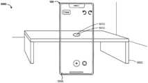
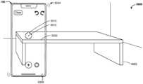
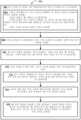
일부 실시예들에 따르면, 방법은 터치 감응형 디스플레이 및 하나 이상의 카메라들을 갖는 전자 디바이스에서 수행된다. 방법은 터치 감응형 디스플레이 상에 애플리케이션의 사용자 인터페이스를 디스플레이하는 단계를 포함한다. 사용자 인터페이스는 하나 이상의 카메라들 중 적어도 하나의 카메라의 시야의 표현을 포함한다. 시야의 표현은 제1 배율로 디스플레이되고, 시야의 표현은 하나 이상의 카메라들 중 적어도 하나에 의해 검출된 현재의 시각적 데이터에 대한 변화들에 기초하여 시간에 걸쳐 업데이트된다. 시야는 3차원 공간의 적어도 일부를 포함한다. 방법은, 시야의 표현을 디스플레이하는 동안, 터치 감응형 디스플레이 상에서 제1 터치 입력을 검출하는 단계, 및 제1 터치 입력을 검출하는 것에 응답하여, 3차원 공간 내의 제1 위치에 대응하는 시야의 표현 내의 제1 위치에 측정 지점을 부가 및 디스플레이하는 단계를 포함한다. 방법은 또한, 측정 지점을 부가한 이후 그리고 시야의 표현을 계속 디스플레이하는 동안: 하나 이상의 카메라들 중 적어도 하나가 이동됨에 따라, 3차원 공간 내의 제1 위치에 대응하는 시야의 표현 내의 위치에 측정 지점을 디스플레이하는 단계; 시야의 표현 내의 측정 지점의 현재 위치에 대응하는 터치 감응형 디스플레이 상의 위치에서 제2 터치 입력을 검출하는 단계; 및 제2 터치 입력을 검출하는 것에 응답하여, 시야의 표현의 적어도 일부의 디스플레이를 제1 배율로부터 제1 배율보다 큰 제2 배율로 확대시키는 단계를 포함하며, 여기서 시야의 표현의 일부의 확대된 디스플레이는 측정 지점을 포함한다.In some embodiments, a method is performed in an electronic device having a touch-sensitive display and one or more cameras. The method comprises displaying a user interface of an application on the touch-sensitive display. The user interface comprises a representation of a field of view of at least one of the one or more cameras. The representation of the field of view is displayed at a first magnification, and the representation of the field of view is updated over time based on changes to current visual data detected by at least one of the one or more cameras. The field of view comprises at least a portion of three-dimensional space. The method comprises, while displaying the representation of the field of view, detecting a first touch input on the touch-sensitive display, and, in response to detecting the first touch input, adding and displaying a measurement point at a first location in the representation of the field of view corresponding to a first location in the three-dimensional space. The method also comprises, after adding the measurement point and while continuing to display the representation of the field of view: displaying the measurement point at a location in the representation of the field of view corresponding to the first location in the three-dimensional space as at least one of the one or more cameras is moved; A step of detecting a second touch input at a location on the touch-sensitive display corresponding to a current location of a measurement point within the representation of the field of view; and, in response to detecting the second touch input, magnifying display of at least a portion of the representation of the field of view from a first magnification to a second magnification greater than the first magnification, wherein the magnified display of the portion of the representation of the field of view includes the measurement point.
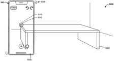
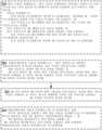
일부 실시예들에 따르면, 방법은, 터치 감응형 디스플레이, 터치 감응형 디스플레이와의 접촉들의 세기들을 검출하기 위한 하나 이상의 센서들, 및 하나 이상의 카메라들을 갖는 전자 디바이스에서 수행된다. 방법은 터치 감응형 디스플레이 상에 애플리케이션의 사용자 인터페이스를 디스플레이하는 단계를 포함한다. 사용자 인터페이스는 하나 이상의 카메라들 중 적어도 하나의 카메라의 시야의 표현을 포함한다. 시야의 표현은 하나 이상의 카메라들 중 적어도 하나에 의해 검출된 현재의 시각적 데이터에 대한 변화들에 기초하여 시간에 걸쳐 업데이트된다. 사용자 인터페이스는 또한 시야의 표현 위에 디스플레이되는 측정 지점 생성 표시자를 포함한다. 시야는 3차원 공간의 적어도 일부를 포함한다. 방법은, 터치 감응형 디스플레이 상에서 접촉을 검출하는 단계, 및 터치 감응형 디스플레이 상에서 접촉을 계속 검출하는 동안, 측정 지점 생성 표시자가 3차원 공간 내의 제1 위치에 대응하는 시야의 표현 내의 제1 위치 위에 디스플레이되는 동안, 그리고 제1 기준들이 충족된다는 결정에 따라 - 제1 기준들은 제1 기준들이 충족되기 위해 접촉의 세기가 개개의 세기 임계치를 충족시킨다는 요건을 포함함 -, 3차원 공간 내의 제1 위치에 대응하는 시야의 표현에 제1 측정 지점을 부가 및 디스플레이하는 단계를 포함한다. 방법은 또한, 제1 측정 지점을 부가한 이후, 전자 디바이스가 이동됨에 따라 시야의 표현을 업데이트하는 단계를 포함한다. 방법은, 전자 디바이스가 이동된 이후, 측정 지점 생성 표시자가 3차원 공간 내의 제2 위치에 대응하는 시야의 표현 내의 제2 위치 위에 디스플레이되는 동안, 측정 지점 생성 표시자가 3차원 공간 내의 제2 위치에 대응하는 시야의 표현 내의 제2 위치 위에 디스플레이되는 동안 제1 기준들이 충족된다는 결정에 따라: 3차원 공간 내의 제2 위치에 대응하는 시야의 표현에 제2 측정 지점을 부가 및 디스플레이하는 단계; 및 제1 측정 지점과 제2 측정 지점을 연결시키는 제1 측정 세그먼트를 디스플레이하는 단계를 더 포함한다.According to some embodiments, a method is performed in an electronic device having a touch-sensitive display, one or more sensors for detecting intensities of contacts with the touch-sensitive display, and one or more cameras. The method comprises displaying a user interface of an application on the touch-sensitive display. The user interface comprises a representation of a field of view of at least one of the one or more cameras. The representation of the field of view is updated over time based on changes to current visual data detected by at least one of the one or more cameras. The user interface also comprises a measurement point generation indicator displayed over the representation of the field of view. The field of view comprises at least a portion of three-dimensional space. The method comprises detecting a contact on a touch-sensitive display, and while continuing to detect the contact on the touch-sensitive display, while a measurement point generation indicator is displayed over a first location in a representation of a field of view corresponding to a first location in three-dimensional space, and upon a determination that first criteria are met, wherein the first criteria include a requirement that an intensity of the contact satisfies a respective intensity threshold for the first criteria to be met, adding and displaying a first measurement point in the representation of the field of view corresponding to the first location in the three-dimensional space. The method also comprises, after adding the first measurement point, updating the representation of the field of view as the electronic device is moved. The method further comprises, after the electronic device is moved, while the measurement point generation indicator is displayed over a second location in the representation of the field of view corresponding to a second location in the three-dimensional space, upon a determination that the first criteria are met, while the measurement point generation indicator is displayed over the second location in the representation of the field of view corresponding to the second location in the three-dimensional space: adding and displaying a second measurement point in the representation of the field of view corresponding to the second location in the three-dimensional space; and further comprising a step of displaying a first measurement segment connecting the first measurement point and the second measurement point.
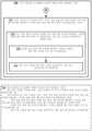
일부 실시예들에 따르면, 방법은 터치 감응형 디스플레이 및 하나 이상의 카메라들을 갖는 전자 디바이스에서 수행된다. 방법은 터치 감응형 디스플레이 상에 애플리케이션의 사용자 인터페이스를 디스플레이하는 단계를 포함한다. 사용자 인터페이스는 하나 이상의 카메라들 중 적어도 하나의 카메라의 시야의 표현을 포함한다. 시야의 표현은 하나 이상의 카메라들 중 적어도 하나에 의해 검출된 현재의 시각적 데이터에 대한 변화들에 기초하여 시간에 걸쳐 업데이트된다. 사용자 인터페이스는 시야의 표현 위에 디스플레이되는 측정 지점 생성 표시자를 포함한다. 시야는 3차원 공간의 적어도 일부를 포함한다. 방법은, 시야의 표현을 디스플레이하는 동안, 3차원 공간 내의 제1 위치에 대응하는 시야의 표현 내의 위치에서 앵커 지점을 결정하는 단계를 포함한다. 방법은 또한, 하나 이상의 카메라들 중 적어도 하나가 이동됨에 따라, 측정 지점 생성 표시자가 앵커 지점 위에 있는 동안, 터치 입력이 제1 기준들을 충족시키면 측정 지점이 앵커 지점에 부가될 것이라는 것을 표시하기 위해 측정 지점 생성 표시자의 시각적 외관을 변화시키는 단계를 포함한다. 방법은, 제1 기준들을 충족시키는 제1 터치 입력을 터치 감응형 디스플레이 상에서 검출하는 단계, 및 제1 기준들을 충족시키는 제1 터치 입력을 검출하는 것에 응답하여: 제1 기준들이 충족될 때 측정 지점 생성 표시자가 앵커 지점 위에 있다는 결정에 따라, 3차원 공간 내의 제1 위치에 대응하는 시야의 표현 내의 앵커 지점에 제1 측정 지점을 부가 및 디스플레이하는 단계; 및 제1 기준들이 충족될 때 측정 지점 생성 표시자가 앵커 지점 위에 있지 않다는 결정에 따라, 앵커 지점으로부터 멀리 떨어진 시야의 표현 내의 제1 위치에 제1 측정 지점을 부가 및 디스플레이하는 단계를 더 포함한다.In some embodiments, a method is performed in an electronic device having a touch-sensitive display and one or more cameras. The method comprises displaying a user interface of an application on the touch-sensitive display. The user interface comprises a representation of a field of view of at least one of the one or more cameras. The representation of the field of view is updated over time based on changes to current visual data detected by at least one of the one or more cameras. The user interface comprises a measurement point generation indicator displayed over the representation of the field of view. The field of view comprises at least a portion of a three-dimensional space. The method comprises, while displaying the representation of the field of view, determining an anchor point at a location within the representation of the field of view corresponding to a first location within the three-dimensional space. The method also comprises, while at least one of the one or more cameras is moved, changing a visual appearance of the measurement point generation indicator to indicate that a measurement point is to be added to the anchor point if a touch input satisfies first criteria while the measurement point generation indicator is over the anchor point. The method further includes the steps of detecting a first touch input on the touch-sensitive display that satisfies first criteria, and in response to detecting the first touch input that satisfies the first criteria: adding and displaying a first measurement point at the anchor point in a representation of the field of view corresponding to a first location in the three-dimensional space, in response to a determination that the measurement point generation indicator is over the anchor point when the first criteria are met; and adding and displaying the first measurement point at a first location in the representation of the field of view remote from the anchor point, in response to a determination that the measurement point generation indicator is not over the anchor point when the first criteria are met.
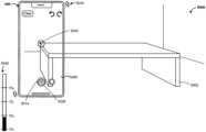
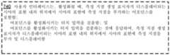
일부 실시예들에 따르면, 방법은 디스플레이, 입력 디바이스, 및 하나 이상의 카메라들을 갖는 전자 디바이스에서 수행된다. 방법은, 디스플레이 상에 애플리케이션의 사용자 인터페이스를 디스플레이하는 단계를 포함한다. 사용자 인터페이스는 하나 이상의 카메라들 중 적어도 하나의 카메라의 시야의 표현을 포함한다. 시야의 표현은 하나 이상의 카메라들 중 적어도 하나에 의해 검출된 현재의 시각적 데이터에 대한 변화들에 기초하여 시간에 걸쳐 업데이트된다. 시야는 3차원 공간 내의 물리적 물체를 포함한다. 방법은, 시야의 표현을 디스플레이하는 동안, 입력 디바이스를 통해, 물리적 물체에 대응하는 제1 측정의 표현을 시야의 표현 위에 부가하는 하나 이상의 사용자 입력들을 검출하는 단계를 포함한다. 방법은 또한, 시야의 표현 위에, 제1 측정의 표현 및 제1 측정을 설명하는 제1 라벨을 동시에 디스플레이하는 단계를 포함하며, 여기서: 전자 디바이스와 물리적 물체 사이의 제1 거리가 제1 임계 거리보다 작다는 결정에 따라, 제1 라벨은 제1 임계 크기로 디스플레이되고; 전자 디바이스와 물리적 물체 사이의 제1 거리가 제1 임계 거리보다 큰 제2 임계 거리보다 크다는 결정에 따라, 제1 라벨은 제1 임계 크기보다 작은 제2 임계 크기로 디스플레이되고; 전자 디바이스와 물리적 물체 사이의 제1 거리가 제1 임계 거리와 제2 임계 거리 사이에 있다는 결정에 따라, 제1 라벨은 전자 디바이스와 물리적 물체 사이의 제1 거리에 의존하는, 제1 임계 크기와 제2 임계 크기 사이의 크기로 디스플레이된다.In some embodiments, a method is performed on an electronic device having a display, an input device, and one or more cameras. The method comprises displaying a user interface of an application on the display. The user interface comprises a representation of a field of view of at least one of the one or more cameras. The representation of the field of view is updated over time based on changes to current visual data detected by at least one of the one or more cameras. The field of view comprises a physical object in three-dimensional space. The method comprises detecting, via the input device, one or more user inputs while displaying the representation of the field of view, a representation of a first measurement corresponding to the physical object over the representation of the field of view. The method also comprises concurrently displaying, over the representation of the field of view, a representation of the first measurement and a first label describing the first measurement, wherein: upon determining that a first distance between the electronic device and the physical object is less than a first threshold distance, the first label is displayed at a first threshold size; upon determining that the first distance between the electronic device and the physical object is greater than a second threshold distance, the first label is displayed at a second threshold size that is less than the first threshold size; Upon determining that the first distance between the electronic device and the physical object is between the first threshold distance and the second threshold distance, the first label is displayed with a size between the first threshold size and the second threshold size, which is dependent on the first distance between the electronic device and the physical object.
일부 실시예들에 따르면, 방법은 디스플레이, 입력 디바이스, 및 하나 이상의 카메라들을 갖는 전자 디바이스에서 수행된다. 방법은, 디스플레이 상에 애플리케이션의 사용자 인터페이스를 디스플레이하는 단계를 포함한다. 사용자 인터페이스는 하나 이상의 카메라들 중 적어도 하나의 카메라의 시야의 표현을 포함한다. 시야의 표현은 하나 이상의 카메라들 중 적어도 하나에 의해 검출된 현재의 시각적 데이터에 대한 변화들에 기초하여 시간에 걸쳐 업데이트된다. 시야는 3차원 공간 내의 물리적 물체를 포함한다. 방법은, 시야의 표현을 디스플레이하는 동안, 입력 디바이스를 통해, 물리적 물체에 대응하는 제1 측정의 표현을 시야의 표현 위에 부가하는 하나 이상의 사용자 입력들을 검출하는 단계를 포함하며, 여기서 제1 측정의 표현은 물리적 물체 상의 제1 위치에 대응하는 제1 종점을 포함하고, 제1 측정의 표현은 물리적 물체 상의 제2 위치에 대응하는 제2 종점을 포함하며; 제1 측정의 표현은 제1 종점과 제2 종점을 연결시키는 제1 라인 세그먼트를 포함한다. 방법은 또한, 제1 측정에 부분적으로 기초하여, 제1 측정의 제1 라인 세그먼트에 인접하는 시야의 표현 내의 제1 영역을 결정하는 단계를 포함하며, 여기서 제1 영역은 3차원 공간 내의 물리적 직사각형 영역에 대응한다. 방법은, 사용자 인터페이스에 제1 영역의 표시를 디스플레이하는 단계를 더 포함하며, 여기서 표시는 시야의 표현 내의 제1 영역 상에 오버레이된다.In some embodiments, a method is performed in an electronic device having a display, an input device, and one or more cameras. The method comprises displaying a user interface of an application on the display. The user interface comprises a representation of a field of view of at least one of the one or more cameras. The representation of the field of view is updated over time based on changes to current visual data detected by at least one of the one or more cameras. The field of view comprises a physical object in three-dimensional space. The method comprises detecting, through the input device, while displaying the representation of the field of view, one or more user inputs that add a representation of a first measurement corresponding to the physical object over the representation of the field of view, wherein the representation of the first measurement comprises a first endpoint corresponding to a first location on the physical object, and the representation of the first measurement comprises a second endpoint corresponding to a second location on the physical object; and the representation of the first measurement comprises a first line segment connecting the first endpoint and the second endpoint. The method also includes a step of determining, based in part on the first measurement, a first region within the representation of the field of view adjacent to a first line segment of the first measurement, wherein the first region corresponds to a physical rectangular region within the three-dimensional space. The method further includes a step of displaying an indicia of the first region on the user interface, wherein the indicia is overlaid on the first region within the representation of the field of view.
일부 실시예들에 따르면, 방법은 터치 감응형 디스플레이 및 하나 이상의 카메라들을 갖는 전자 디바이스에서 수행된다. 방법은 터치 감응형 디스플레이 상에 애플리케이션의 제1 사용자 인터페이스를 디스플레이하는 단계를 포함한다. 제1 사용자 인터페이스는 하나 이상의 카메라들 중 적어도 하나의 카메라의 시야의 표현을 포함한다. 시야의 표현은 하나 이상의 카메라들 중 적어도 하나에 의해 검출된 현재의 시각적 데이터에 대한 변화들에 기초하여 시간에 걸쳐 업데이트된다. 시야는 3차원 공간 내의 물리적 물체를 포함한다. 물리적 물체의 측정의 표현은 시야의 표현 내의 물리적 물체의 이미지 상에 중첩된다. 방법은, 제1 사용자 인터페이스를 디스플레이하는 동안, 측정의 표현 상의 터치 감응형 디스플레이 상에서 제1 터치 입력을 검출하는 단계를 포함한다. 방법은, 측정의 표현 상의 터치 감응형 디스플레이 상에서 제1 터치 입력을 검출하는 것에 응답하여, 측정에 관한 정보를 공유하기 위한 프로세스를 개시하는 단계를 더 포함한다.In some embodiments, a method is performed in an electronic device having a touch-sensitive display and one or more cameras. The method comprises displaying a first user interface of an application on the touch-sensitive display. The first user interface comprises a representation of a field of view of at least one of the one or more cameras. The representation of the field of view is updated over time based on changes to current visual data detected by at least one of the one or more cameras. The field of view comprises a physical object in three-dimensional space. A representation of a measurement of the physical object is superimposed on an image of the physical object in the representation of the field of view. The method comprises detecting a first touch input on the touch-sensitive display on the representation of the measurement while displaying the first user interface. The method further comprises initiating a process for sharing information about the measurement in response to detecting the first touch input on the touch-sensitive display on the representation of the measurement.
일부 실시예들에 따르면, 방법은 디스플레이, 입력 디바이스, 및 하나 이상의 카메라들을 갖는 전자 디바이스에서 수행된다. 방법은, 디스플레이 상에 애플리케이션의 사용자 인터페이스를 디스플레이하는 단계를 포함한다. 사용자 인터페이스는 하나 이상의 카메라들 중 적어도 하나의 카메라의 시야의 표현을 포함한다. 시야의 표현은 하나 이상의 카메라들 중 적어도 하나에 의해 검출된 현재의 시각적 데이터에 대한 변화들에 기초하여 시간에 걸쳐 업데이트된다. 시야는 3차원 공간의 적어도 일부를 포함한다. 방법은, 하나 이상의 카메라들 중 적어도 하나의 카메라의 시야를 제1 방향으로 이동시키는 전자 디바이스의 이동을 검출하는 단계를 포함한다. 방법은 또한, 시야를 제1 방향으로 이동시키는 전자 디바이스의 이동을 검출하는 동안: 전자 디바이스의 이동에 따라 시야의 표현을 업데이트하는 단계; 제1 방향을 따라 연장되는 시야의 표현에서 하나 이상의 제1 요소들을 식별하는 단계; 및 하나 이상의 제1 요소들의 결정에 적어도 부분적으로 기초하여, 제1 방향으로 연장되고 하나 이상의 제1 식별된 요소들 중 하나에 대응하는 제1 가이드를 시야의 표현에 디스플레이하는 단계를 포함한다.In some embodiments, a method is performed on an electronic device having a display, an input device, and one or more cameras. The method comprises displaying a user interface of an application on the display. The user interface comprises a representation of a field of view of at least one of the one or more cameras. The representation of the field of view is updated over time based on changes to current visual data detected by at least one of the one or more cameras. The field of view comprises at least a portion of three-dimensional space. The method comprises detecting movement of the electronic device that moves the field of view of at least one of the one or more cameras in a first direction. The method also comprises, while detecting movement of the electronic device that moves the field of view in the first direction: updating the representation of the field of view in response to the movement of the electronic device; identifying one or more first elements in the representation of the field of view extending along the first direction; and displaying, at least in part based on the determination of the one or more first elements, a first guide in the representation of the field of view that extends in the first direction and corresponds to one of the one or more first identified elements.
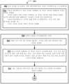
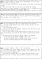
일부 실시예들에 따르면, 방법은, 하나 이상의 입력 디바이스들, 하나 이상의 디스플레이 디바이스들, 및 하나 이상의 카메라들을 갖는 전자 디바이스에서 수행된다: 방법은, 하나 이상의 디스플레이 디바이스들을 통해, 물리적 공간의 표현을 포함하는 사용자 인터페이스를 디스플레이하는 단계를 포함한다. 방법은, 물리적 공간의 표현을 디스플레이하는 동안, 물리적 공간의 표현에서 가상 주석을 생성하기 위한 하나 이상의 입력들의 제1 세트를 수신하는 단계를 포함한다. 방법은 또한, 하나 이상의 입력들의 제1 세트를 수신하는 것에 응답하여, 물리적 공간의 표현에 제1 가상 주석을 부가하는 단계를 포함한다. 제1 가상 주석은 물리적 공간의 표현의 일부에 링크된다. 방법은 또한, 물리적 공간의 표현에 제1 가상 주석을 부가한 이후, 물리적 공간의 표현과 연관된 하나 이상의 입력들의 제2 세트를 수신하는 단계를 포함한다. 방법은, 물리적 공간의 표현과 연관된 하나 이상의 입력들의 제2 세트를 수신하는 것에 응답하여: 제1 가상 주석으로부터 임계 거리 내에 있는 물리적 공간의 표현에서 가상 주석을 생성하기 위한 요청에 하나 이상의 입력들의 제2 세트가 대응한다는 결정에 따라, 물리적 공간의 표현에서 제1 가상 주석을 유지하면서 물리적 공간의 표현에서 제2 가상 주석을 생성하는 단계; 및 제1 가상 주석으로부터 임계 거리 외부에 있는 물리적 공간의 표현에서 가상 주석을 생성하기 위한 요청에 하나 이상의 입력들의 제2 세트가 대응한다는 결정에 따라, 물리적 공간의 표현에서 제2 가상 주석을 생성하고 물리적 공간의 표현으로부터 제1 가상 주석을 제거하는 단계를 더 포함한다.According to some embodiments, a method is performed in an electronic device having one or more input devices, one or more display devices, and one or more cameras: the method comprises displaying a user interface including a representation of a physical space via the one or more display devices. The method comprises receiving, while displaying the representation of the physical space, a first set of one or more inputs for generating a virtual annotation in the representation of the physical space. The method also comprises, in response to receiving the first set of one or more inputs, adding a first virtual annotation to the representation of the physical space. The first virtual annotation is linked to a portion of the representation of the physical space. The method also comprises, after adding the first virtual annotation to the representation of the physical space, receiving a second set of one or more inputs associated with the representation of the physical space. The method further comprises: in response to receiving a second set of one or more inputs associated with a representation of the physical space: generating a second virtual annotation in the representation of the physical space while maintaining the first virtual annotation in the representation of the physical space in response to a determination that the second set of one or more inputs corresponds to a request to generate a virtual annotation in the representation of the physical space within a threshold distance from the first virtual annotation; and in response to a determination that the second set of one or more inputs corresponds to a request to generate a virtual annotation in the representation of the physical space outside the threshold distance from the first virtual annotation, generating the second virtual annotation in the representation of the physical space and removing the first virtual annotation from the representation of the physical space.
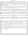
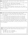
일부 실시예들에 따르면, 방법은, 하나 이상의 입력 디바이스들, 하나 이상의 디스플레이 디바이스들, 및 하나 이상의 카메라들을 갖는 전자 디바이스에서 수행된다. 방법은, 하나 이상의 디스플레이 디바이스들을 통해 주석 배치 사용자 인터페이스를 디스플레이하는 단계를 포함한다. 주석 배치 사용자 인터페이스는, 물리적 공간의 표현; 및 주석 배치 입력을 검출하는 것에 응답하여 가상 주석이 물리적 공간의 표현에 배치될 위치를 표시하는 배치 사용자 인터페이스 요소를 포함한다. 방법은, 주석 배치 사용자 인터페이스를 디스플레이하는 동안, 물리적 공간에 대한 하나 이상의 카메라들 중 적어도 하나의 카메라의 이동을 검출하는 단계를 포함한다. 하나 이상의 카메라들 중 적어도 하나의 카메라의 이동은 배치 사용자 인터페이스 요소가 물리적 공간의 제1 부분에 대응하는 물리적 공간의 표현 내의 위치에 디스플레이되는 동안 시작된다. 방법은, 물리적 공간에 대한 하나 이상의 카메라들 중 적어도 하나의 카메라의 이동을 검출하는 것에 응답하여, 물리적 공간의 제1 부분과는 상이한 물리적 공간의 제2 부분에 대응하는 물리적 공간의 표현 내의 위치로 배치 사용자 인터페이스 요소를 이동시키는 단계, 및 물리적 공간에 대한 하나 이상의 카메라들 중 적어도 하나의 카메라의 이동에 따라 주석 배치 사용자 인터페이스의 외관을 업데이트하는 단계를 포함하며, 이동시키고 업데이트하는 단계는, 물리적 공간의 표현 내의 대응하는 물체가 가상 주석에 링크될 수 있는 물리적 공간의 제2 부분 내의 물체를 전자 디바이스가 식별할 수 없다는 결정에 따라, 배치 사용자 인터페이스 요소의 적어도 일부를 디스플레이하는 것을 중단하는 단계; 및 물리적 공간의 표현 내의 대응하는 물체가 가상 주석에 링크될 수 있는 물리적 공간의 제2 부분 내의 물체를 디바이스가 식별했다는 결정에 따라, 배치 사용자 인터페이스 요소의 디스플레이를 유지하는 단계를 포함한다.According to some embodiments, a method is performed in an electronic device having one or more input devices, one or more display devices, and one or more cameras. The method comprises displaying an annotation placement user interface via the one or more display devices. The annotation placement user interface comprises: a representation of a physical space; and a placement user interface element that indicates a location at which a virtual annotation is to be placed in the representation of the physical space in response to detecting an annotation placement input. The method comprises detecting, while displaying the annotation placement user interface, movement of at least one camera of the one or more cameras relative to the physical space. The movement of the at least one camera of the one or more cameras is initiated while the placement user interface element is displayed at a location within the representation of the physical space corresponding to a first portion of the physical space. The method comprises, in response to detecting movement of at least one camera of the one or more cameras relative to the physical space, moving a placement user interface element to a location in a representation of the physical space corresponding to a second portion of the physical space that is different from the first portion of the physical space, and updating an appearance of the annotation placement user interface in response to the movement of the at least one camera of the one or more cameras relative to the physical space, wherein the moving and updating comprises: ceasing to display at least a portion of the placement user interface element in response to a determination that the electronic device cannot identify an object in the second portion of the physical space to which the corresponding object in the representation of the physical space can be linked to the virtual annotation; and maintaining display of the placement user interface element in response to a determination that the device has identified an object in the second portion of the physical space to which the corresponding object in the representation of the physical space can be linked to the virtual annotation.
일부 실시예들에 따르면, 컴퓨터 시스템(예를 들어, 전자 디바이스)은 디스플레이 생성 컴포넌트(예를 들어, 디스플레이, 프로젝터, 헤드-업 디스플레이 등), 하나 이상의 카메라들(예를 들어, 카메라들의 시야 내에 있는 콘텐츠들의 적어도 일부의 라이브 프리뷰를 계속 제공하고, 선택적으로, 카메라들의 시야 내의 콘텐츠들을 캡처하는 이미지 프레임들의 하나 이상의 스트림들을 포함하는 비디오 출력들을 생성하는 비디오 카메라들), 및 하나 이상의 입력 디바이스들(예를 들어, 터치 감응형 원격 제어부와 같은 터치 감응형 표면, 또는 디스플레이 생성 컴포넌트로서 또한 기능하는 터치 스크린 디스플레이, 마우스, 조이스틱, 완드 제어기 및/또는 사용자의 손들과 같은 사용자의 하나 이상의 특징부들의 위치를 추적하는 카메라들), 선택적으로는 하나 이상의 자세 센서들, 선택적으로는 터치 감응형 표면과의 접촉들의 세기들을 검출하기 위한 하나 이상의 센서들, 선택적으로는 하나 이상의 촉각적 출력 생성기들, 하나 이상의 프로세서들, 및 하나 이상의 프로그램들을 저장하는 메모리를 포함하며; 하나 이상의 프로그램들은 하나 이상의 프로세서들에 의해 실행되도록 구성되고, 하나 이상의 프로그램들은 본 명세서에 설명되는 방법들 중 임의의 방법의 동작들을 수행하거나 또는 이들의 수행을 야기하기 위한 명령어들을 포함한다. 일부 실시예들에 따르면, 컴퓨터 판독가능 저장 매체는 명령어들을 내부에 저장하며, 명령어들은, 디스플레이 생성 컴포넌트, 하나 이상의 카메라들, 하나 이상의 입력 디바이스들, 선택적으로는 하나 이상의 자세 센서들, 선택적으로는 터치 감응형 표면과의 접촉들의 세기들을 검출하기 위한 하나 이상의 센서들, 및 선택적으로는 하나 이상의 촉각적 출력 생성기들을 포함하는(그리고/또는 이들과 통신하는) 컴퓨터 시스템에 의해 실행될 때, 컴퓨터 시스템으로 하여금 본 명세서에 설명되는 방법들 중 임의의 방법의 동작들을 수행하게 하거나 또는 이들의 수행을 야기한다. 일부 실시예들에 따르면, 디스플레이 생성 컴포넌트, 하나 이상의 카메라들, 하나 이상의 입력 디바이스들, 선택적으로는 하나 이상의 자세 센서들, 선택적으로는 터치 감응형 표면과의 접촉들의 세기들을 검출하기 위한 하나 이상의 센서들, 선택적으로는 하나 이상의 촉각적 출력 생성기들, 메모리, 및 메모리에 저장된 하나 이상의 프로그램들을 실행하기 위한 하나 이상의 프로세서들을 포함하는(그리고/또는 이들과 통신하는) 컴퓨터 시스템 상의 그래픽 사용자 인터페이스는 본 명세서에 설명되는 방법들 중 임의의 방법에서 설명되는 바와 같이, 입력들에 응답하여 업데이트되는, 본 명세서에 설명되는 방법들 중 임의의 방법에서 디스플레이되는 요소들 중 하나 이상을 포함한다. 일부 실시예들에 따르면, 컴퓨터 시스템은, 디스플레이 생성 컴포넌트, 하나 이상의 카메라들, 하나 이상의 입력 디바이스들, 선택적으로는 하나 이상의 자세 센서들, 선택적으로는 터치 감응형 표면과의 접촉들의 세기들을 검출하기 위한 하나 이상의 센서들, 선택적으로는 하나 이상의 촉각적 출력 생성기들, 본 명세서에 설명되는 방법들 중 임의의 방법의 동작들을 수행하거나 또는 이들의 수행을 야기하기 위한 수단을 포함한다(그리고/또는 이들과 통신한다). 일부 실시예들에 따르면, 디스플레이 생성 컴포넌트, 하나 이상의 카메라들, 하나 이상의 입력 디바이스들, 선택적으로는 하나 이상의 자세 센서들, 선택적으로는 터치 감응형 표면과의 접촉들의 세기들을 검출하기 위한 하나 이상의 센서들, 및 선택적으로는 하나 이상의 촉각적 출력 생성기들을 포함하는(그리고/또는 이들과 통신하는) 컴퓨터 시스템에서의 사용을 위한 정보 프로세싱 장치는 본 명세서에 설명되는 방법들 중 임의의 방법의 동작들을 수행하거나 또는 이들의 수행을 야기하기 위한 수단을 포함한다.According to some embodiments, a computer system (e.g., an electronic device) includes a display generating component (e.g., a display, a projector, a head-up display, etc.), one or more cameras (e.g., video cameras that continuously provide a live preview of at least a portion of content within the cameras' field of view, and optionally, video cameras that generate video outputs comprising one or more streams of image frames capturing content within the cameras' field of view), and one or more input devices (e.g., a touch-sensitive surface, such as a touch-sensitive remote control, or a touch screen display that also functions as a display generating component, a mouse, a joystick, a wand controller, and/or cameras that track the position of one or more features of a user, such as the user's hands), optionally one or more posture sensors, optionally one or more sensors for detecting intensities of contacts with the touch-sensitive surface, optionally one or more tactile output generators, one or more processors, and a memory storing one or more programs; One or more programs are configured to be executed by one or more processors, and the one or more programs include instructions for performing or causing the performing of any of the methods described herein. According to some embodiments, a computer-readable storage medium has instructions stored therein, which when executed by a computer system comprising (and/or in communication with) a display generating component, one or more cameras, one or more input devices, optionally one or more attitude sensors, optionally one or more sensors for detecting intensities of contacts with a touch-sensitive surface, and optionally one or more tactile output generators, cause the computer system to perform or cause the performing of any of the methods described herein. In some embodiments, a graphical user interface on a computer system (and/or in communication with) a display generating component, one or more cameras, one or more input devices, optionally one or more attitude sensors, optionally one or more sensors for detecting intensities of contacts with a touch-sensitive surface, optionally one or more tactile output generators, a memory, and one or more processors for executing one or more programs stored in the memory includes one or more of the elements displayed in any of the methods described herein, which are updated in response to inputs, as described in any of the methods described herein. In some embodiments, the computer system includes (and/or in communication with) the display generating component, one or more cameras, one or more input devices, optionally one or more attitude sensors, optionally one or more sensors for detecting intensities of contacts with a touch-sensitive surface, optionally one or more tactile output generators, and means for performing or causing the performing of the operations of any of the methods described herein. According to some embodiments, an information processing apparatus for use in a computer system comprising (and/or in communication with) a display generating component, one or more cameras, one or more input devices, optionally one or more attitude sensors, optionally one or more sensors for detecting intensities of contacts with a touch-sensitive surface, and optionally one or more tactile output generators, comprises means for performing or causing the performance of the operations of any of the methods described herein.
따라서, 디스플레이 생성 컴포넌트, 하나 이상의 카메라들, 하나 이상의 입력 디바이스들, 선택적으로는 하나 이상의 자세 센서들, 선택적으로는 터치 감응형 표면과의 접촉들의 세기들을 검출하기 위한 하나 이상의 센서들, 및 선택적으로는 하나 이상의 촉각적 출력 생성기들을 갖는(그리고/또는 이들과 통신하는) 컴퓨터 시스템들에는 가상/증강 현실 환경들을 사용하여 물리적 물체들을 측정하기 위한 개선된 방법들 및 인터페이스들이 제공되어, 그에 의해, 그러한 컴퓨터 시스템들을 이용하여 유효성, 효율성 및 사용자 만족도를 증가시킨다. 그러한 방법들 및 인터페이스들은 가상/증강 현실 환경들을 사용하여 물리적 물체들을 측정하기 위한 종래의 방법들을 보완하거나 대체할 수 있다.Accordingly, computer systems having (and/or in communication with) a display generating component, one or more cameras, one or more input devices, optionally one or more attitude sensors, optionally one or more sensors for detecting intensities of contacts with a touch-sensitive surface, and optionally one or more tactile output generators are provided with improved methods and interfaces for measuring physical objects using virtual/augmented reality environments, thereby increasing the effectiveness, efficiency and user satisfaction of using such computer systems. Such methods and interfaces can complement or replace conventional methods for measuring physical objects using virtual/augmented reality environments.
다양하게 설명된 실시예들의 보다 양호한 이해를 위해, 유사한 도면 부호들이 도면 전체에 걸쳐서 대응 부분들을 나타내는 하기의 도면들과 관련하여 하기의 발명을 실시하기 위한 구체적인 내용이 참조되어야 한다.
도 1a는 일부 실시예들에 따른, 터치 감응형 디스플레이를 갖는 휴대용 다기능 디바이스를 예시하는 블록도이다.
도 1b는 일부 실시예들에 따른, 이벤트 처리를 위한 예시적인 컴포넌트들을 예시하는 블록도이다.
도 1c는 일부 실시예들에 따른 촉각적 출력 모듈을 예시하는 블록도이다.
도 2는 일부 실시예들에 따른, 터치 스크린을 갖는 휴대용 다기능 디바이스를 예시한다.
도 3a는 일부 실시예들에 따른, 디스플레이 및 터치 감응형 표면을 갖는 예시적인 다기능 디바이스의 블록도이다.
도 3b 및 도 3c는 일부 실시예들에 따른 예시적인 컴퓨터 시스템들의 블록도들이다.
도 4a는 일부 실시예들에 따른, 휴대용 다기능 디바이스 상의 애플리케이션들의 메뉴에 대한 예시적인 사용자 인터페이스를 예시한다.
도 4b는 일부 실시예들에 따른, 디스플레이와는 별개인 터치 감응형 표면을 갖는 다기능 디바이스에 대한 예시적인 사용자 인터페이스를 예시한다.
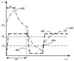
도 4c 내지 도 4e는 일부 실시예들에 따른 동적 세기 임계치들의 예들을 예시한다.
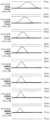
도 4f 내지 도 4k는 일부 실시예들에 따른 샘플 촉각적 출력 패턴들의 세트를 예시한다.
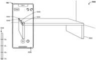
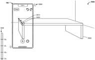
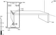
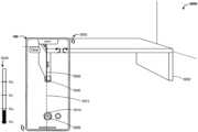
도 5a 내지 도 5co는 일부 실시예들에 따른, 증강 현실 환경을 사용하여 물리적 공간의 측정들을 행하기 위한 예시적인 사용자 인터페이스들을 예시한다.
도 6a 내지 도 6c는 일부 실시예들에 따른, 증강 현실 환경을 사용하여 물리적 공간의 측정들을 행하기 위해 애플리케이션과 상호작용하기 위한 프로세스의 흐름도들이다.
도 7a 내지 도 7e는 일부 실시예들에 따른, 증강 현실 환경에서 물리적 공간의 디스플레이된 표현에 측정들을 부가하기 위한 프로세스의 흐름도들이다.
도 8a 내지 도 8c는 일부 실시예들에 따른, 증강 현실 환경에서 자동으로 결정된 앵커 지점들에 가상 측정 지점들을 부가하기 위한 프로세스의 흐름도들이다.
도 9a 및 도 9b는 일부 실시예들에 따른, 증강 현실 환경에서 물리적 공간의 측정들에 대한 라벨들을 디스플레이하기 위한 프로세스의 흐름도들이다.
도 10a 및 도 10b는 일부 실시예들에 따른, 증강 현실 환경에서 물리적 공간 내의 직사각형 영역들을 측정하고 이들과 상호작용하기 위한 프로세스의 흐름도들이다.
도 11a 및 도 11b는 일부 실시예들에 따른, 증강 현실 환경에서의 측정 정보와 상호작용하고 이를 관리하기 위한 프로세스의 흐름도들이다.
도 12a 내지 도 12c는 일부 실시예들에 따른, 증강 현실 환경에서 자동으로 결정된 정렬 가이드들을 제공하기 위한 프로세스의 흐름도들이다.
도 13a 내지 도 13c는 일부 실시예들에 따른, 증강 현실 환경에서 이전에 부가된 가상 주석들을 자동으로 제거하기 위한 프로세스의 흐름도들이다.
도 14a 내지 도 14d는 일부 실시예들에 따른, 증강 현실 환경 내의 대응하는 표현들이 추적될 수 있는 물체들로서 물리적 공간 내의 물체들이 식별되었는지 여부를 표시하기 위한 프로세스의 흐름도들이다.For a better understanding of the various described embodiments, reference should be made to the following detailed description taken in conjunction with the drawings in which like reference numerals represent corresponding parts throughout the drawings.
FIG. 1A is a block diagram illustrating a portable multifunction device having a touch-sensitive display, according to some embodiments.
FIG. 1b is a block diagram illustrating exemplary components for event processing according to some embodiments.
FIG. 1c is a block diagram illustrating a tactile output module according to some embodiments.
FIG. 2 illustrates a portable multifunction device having a touch screen, according to some embodiments.
FIG. 3A is a block diagram of an exemplary multifunction device having a display and a touch-sensitive surface, according to some embodiments.
FIGS. 3b and 3c are block diagrams of exemplary computer systems according to some embodiments.
FIG. 4A illustrates an exemplary user interface for a menu of applications on a portable multifunction device, according to some embodiments.
FIG. 4b illustrates an exemplary user interface for a multifunction device having a touch-sensitive surface separate from a display, according to some embodiments.
Figures 4c to 4e illustrate examples of dynamic intensity thresholds according to some embodiments.
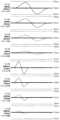
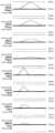
FIGS. 4F through 4K illustrate a set of sample tactile output patterns according to some embodiments.
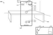
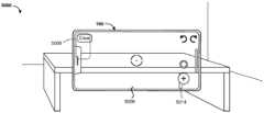
FIGS. 5A through 5C illustrate exemplary user interfaces for making measurements of physical space using an augmented reality environment, according to some embodiments.
FIGS. 6A through 6C are flowcharts of a process for interacting with an application to make measurements of a physical space using an augmented reality environment, according to some embodiments.
FIGS. 7A through 7E are flowcharts of a process for adding measurements to a displayed representation of physical space in an augmented reality environment, according to some embodiments.
FIGS. 8A through 8C are flowcharts of a process for adding virtual measurement points to automatically determined anchor points in an augmented reality environment, according to some embodiments.
FIGS. 9A and 9B are flowcharts of a process for displaying labels for measurements of physical space in an augmented reality environment, according to some embodiments.
FIGS. 10A and 10B are flowcharts of a process for measuring and interacting with rectangular areas within physical space in an augmented reality environment, according to some embodiments.
FIGS. 11A and 11B are flowcharts of a process for interacting with and managing measurement information in an augmented reality environment, according to some embodiments.
FIGS. 12A through 12C are flowcharts of a process for providing automatically determined alignment guides in an augmented reality environment, according to some embodiments.
FIGS. 13A through 13C are flowcharts of a process for automatically removing previously added virtual annotations in an augmented reality environment, according to some embodiments.
FIGS. 14A through 14D are flowcharts of a process for indicating whether objects in a physical space have been identified as objects whose corresponding representations within an augmented reality environment can be tracked, according to some embodiments.
위에서 언급된 바와 같이, 증강 현실 환경들은, 물리적 공간의 뷰를 제공하고 사용자가 물리적 공간 및 그 내부의 물리적 물체들에 대한 측정들을 중첩시킬 수 있게 함으로써, 물리적 공간들 및 그 내부의 물체들의 측정들을 행하는 데 유용하다. 증강 현실 환경들을 이용하여 측정하는 종래의 방법들은 종종 기능이 제한된다. 일부 경우들에서, 종래의 방법들은 (예를 들어, 상이한 측정 기능들에 액세스하기 위한 다수의 디스플레이된 사용자 인터페이스 요소들의 활성화를 통해) 의도된 결과를 달성하기 위해 다수의 별개의 입력들(예를 들어, 제스처들 및 버튼 누르기들 등의 시퀀스)을 요구한다. 본 명세서에 개시된 실시예들은 (예를 들어, 사용자가 더 적은 입력들로 증강 현실 환경에서 상이한 동작들을 수행할 수 있게 함으로써, 그리고/또는 사용자 인터페이스를 단순화함으로써) 사용자가 증강 현실 환경을 이용하여 측정들을 행하기 위한 직관적인 방식을 제공한다. 부가적으로, 본 발명의 실시예들은, 측정되는 물리적 물체들에 관한 그리고 증강 현실 환경에서 수행되는 동작들에 관한 부가적인 정보를 사용자에게 제공하는 개선된 시각적 및 촉각적 피드백을 제공한다.As noted above, augmented reality environments are useful for making measurements of physical spaces and objects therein by providing a view of the physical space and allowing the user to superimpose measurements of the physical space and physical objects therein. Conventional methods of making measurements using augmented reality environments are often limited in their functionality. In some cases, conventional methods require multiple distinct inputs (e.g., sequences of gestures and button presses, etc.) to achieve an intended result (e.g., via activation of multiple displayed user interface elements to access different measurement functions). Embodiments disclosed herein provide an intuitive way for a user to make measurements using an augmented reality environment (e.g., by allowing the user to perform different actions in the augmented reality environment with fewer inputs, and/or by simplifying the user interface). Additionally, embodiments of the present invention provide improved visual and tactile feedback that provides the user with additional information about the physical objects being measured and about actions being performed in the augmented reality environment.
본 명세서에 설명되는 시스템들, 방법들, 및 GUI들은 다수의 방식들로 가상/증강 현실 환경들과의 사용자 인터페이스 상호작용들을 개선시킨다. 예를 들어, 그들은 물리적 공간 내의 특징부들의 자동 검출, 개선된 라벨링, 및 (예를 들어, 개선된 측정 지점 배치 및 영역 인식을 위한) 정렬 가이드들을 제공함으로써 그리고 사용자가 측정 정보와 상호작용하고 이를 관리할 수 있게 함으로써 증강 현실 환경을 사용하여 물리적 공간 내의 특징부들을 측정하는 것을 더 용이하게 만든다.The systems, methods, and GUIs described herein improve user interface interactions with virtual/augmented reality environments in a number of ways. For example, they make it easier to measure features in physical space using an augmented reality environment by providing automatic detection of features in the physical space, improved labeling, and alignment guides (e.g., for improved measurement point placement and area recognition), and by allowing a user to interact with and manage the measurement information.
이하에서, 도 1a 및 도 1b, 도 2, 및 도 3a 내지 도 3c는 예시적인 디바이스들의 설명을 제공한다. 도 4a 및 도 4b 및 도 5a 내지 도 5co는 증강 현실 환경을 사용하여 물리적 공간의 측정들을 행하기 위한 예시적인 콘텍스트들 및 예시적인 사용자 인터페이스들을 예시한다. 도 6a 내지 도 6c는 증강 현실 환경을 사용하여 물리적 공간의 측정들을 행하기 위해 애플리케이션과 상호작용하는 방법의 흐름도를 예시한다. 도 7a 내지 도 7e는 증강 현실 환경에서 물리적 공간의 디스플레이된 표현에 측정들을 부가하는 방법의 흐름도를 도시한다. 도 8a 내지 도 8c는 증강 현실 환경에서 자동으로 결정된 앵커 지점들에 가상 측정 지점을 부가하는 방법의 흐름도를 예시한다. 도 9a 및 도 9b는 증강 현실 환경 내의 물리적 공간의 측정들을 위해 라벨들을 디스플레이하는 방법의 흐름도를 예시한다. 도 10a 및 도 10b는 증강 현실 환경에서 물리적 공간 내의 직사각형 영역들을 측정하고 그와 상호작용하는 방법의 흐름도를 예시한다. 도 11a 및 도 11b는 증강 현실 환경에서의 측정 정보와 상호작용하고 이를 관리하는 방법의 흐름도를 예시한다. 도 12a 내지 도 12c는 증강 현실 환경에서 자동으로 결정된 정렬 가이드들을 제공하는 방법의 흐름도를 예시한다. 도 13a 내지 도 13c는 증강 현실 환경에서 이전에 부가된 가상 주석들을 자동으로 제거하기 위한 프로세스의 흐름도들이다. 도 14a 내지 도 14d는 증강 현실 환경 내의 대응하는 표현들이 추적될 수 있는 물체들로서 물리적 공간 내의 물체들이 식별되었는지 여부를 표시하기 위한 프로세스의 흐름도들이다. 도 5a 내지 도 5co의 사용자 인터페이스들은 도 6a 내지 도 6c, 도 7a 내지 도 7e, 도 8a 내지 도 8c, 도 9a 및 도 9b, 도 10a 및 도 10b, 도 11a 및 도 11b, 도 12a 내지 도 12c, 도 13a 내지 도 13c, 및 도 14a 내지 도 14d의 프로세스들을 예시하기 위해 사용된다.Hereinafter, FIGS. 1A and 1B, FIGS. 2, and 3A-3C provide descriptions of exemplary devices. FIGS. 4A-4B and FIGS. 5A-5Co illustrate exemplary contexts and exemplary user interfaces for making measurements of a physical space using an augmented reality environment. FIGS. 6A-6C illustrate a flowchart of a method for interacting with an application to make measurements of a physical space using an augmented reality environment. FIGS. 7A-7E illustrate a flowchart of a method for adding measurements to a displayed representation of a physical space in an augmented reality environment. FIGS. 8A-8C illustrate a flowchart of a method for adding virtual measurement points to automatically determined anchor points in an augmented reality environment. FIGS. 9A-9B illustrate a flowchart of a method for displaying labels for measurements of a physical space within an augmented reality environment. FIGS. 10A-10B illustrate a flowchart of a method for measuring and interacting with rectangular areas within a physical space in an augmented reality environment. FIGS. 11A through 11B illustrate a flowchart of a method for interacting with and managing measurement information in an augmented reality environment. FIGS. 12A through 12C illustrate a flowchart of a method for providing automatically determined alignment guides in an augmented reality environment. FIGS. 13A through 13C are flowcharts of a process for automatically removing previously added virtual annotations in an augmented reality environment. FIGS. 14A through 14D are flowcharts of a process for indicating whether objects in physical space have been identified as objects whose corresponding representations in the augmented reality environment can be tracked. The user interfaces of FIGS. 5a through 5co are used to illustrate the processes of FIGS. 6a through 6c, 7a through 7e, 8a through 8c, 9a and 9b, 10a and 10b, 11a and 11b, 12a through 12c, 13a through 13c, and 14a through 14d.
예시적인 디바이스들Example devices
이제, 실시예들이 상세하게 참조될 것이며, 그 실시예들의 예들이 첨부 도면들에 예시된다. 하기의 상세한 설명에서, 많은 구체적인 상세사항들이 다양하게 설명된 실시예들의 완전한 이해를 제공하기 위해 기재된다. 그러나, 다양한 설명된 실시예들이 이들 구체적인 상세사항들 없이 실시될 수 있다는 것은 당업자에게 명백할 것이다. 다른 예시들에서, 잘 알려진 방법들, 절차들, 컴포넌트들, 회로들, 및 네트워크들은 실시예들의 태양들을 불필요하게 모호하게 하지 않기 위해 상세히 설명되지 않았다.Reference will now be made in detail to embodiments, examples of which are illustrated in the accompanying drawings. In the following detailed description, numerous specific details are set forth in order to provide a thorough understanding of the various described embodiments. However, it will be apparent to those skilled in the art that the various described embodiments may be practiced without these specific details. In other instances, well-known methods, procedures, components, circuits, and networks have not been described in detail so as not to unnecessarily obscure aspects of the embodiments.
일부 예시들에서, 용어들, 제1, 제2 등이 본 명세서에서 다양한 요소들을 설명하는 데 사용되지만, 이들 요소들은 이들 용어들에 의해 제한되어서는 안 된다는 것이 또한 이해될 것이다. 이들 용어들은 하나의 요소를 다른 요소와 구별하는 데에만 사용된다. 예를 들어, 다양한 설명된 실시예들의 범주로부터 벗어남이 없이, 제1 접촉이 제2 접촉으로 지칭될 수 있고, 유사하게, 제2 접촉이 제1 접촉으로 지칭될 수 있다. 제1 접촉 및 제2 접촉은 둘 모두 접촉이지만, 문맥상 명백히 달리 표시하지 않는 한, 이들이 동일한 접촉인 것은 아니다.In some instances, it will also be understood that although the terms first, second, etc. are used herein to describe various elements, these elements should not be limited by these terms. These terms are only used to distinguish one element from another. For example, without departing from the scope of the various described embodiments, a first contact may be referred to as a second contact, and similarly, a second contact may be referred to as a first contact. Although the first contact and the second contact are both contacts, they are not necessarily the same contact unless the context clearly indicates otherwise.
본 명세서에서 다양하게 설명된 실시예들의 설명에 사용되는 용어는 특정 실시예들을 설명하는 목적만을 위한 것이고, 제한하려는 의도는 아니다. 다양한 설명된 실시예들의 설명 및 첨부된 청구범위에 사용되는 바와 같이, 단수의 형태("a", "an", 및 "the")는 문맥상 명백히 달리 나타내지 않는다면 복수의 형태도 마찬가지로 포함하려는 것으로 의도된다. 또한, 본 명세서에서 사용되는 바와 같은 용어 "및/또는"은 열거되는 연관된 항목들 중 하나 이상의 항목들의 임의의 그리고 모든 가능한 조합들을 나타내고 그들을 포괄하는 것임이 이해될 것이다. 용어들 "포함한다(include)", "포함하는(including)", "포함한다(comprise)", 및/또는 "포함하는(comprising)"은, 본 명세서에서 사용될 때, 언급된 특징들, 정수들, 단계들, 동작들, 요소들, 및/또는 컴포넌트들의 존재를 특정하지만, 하나 이상의 다른 특징들, 정수들, 단계들, 동작들, 요소들, 컴포넌트들, 및/또는 이들의 그룹들의 존재 또는 부가를 배제하지 않음이 추가로 이해될 것이다.The terminology used in the description of the various described embodiments herein is for the purpose of describing particular embodiments only and is not intended to be limiting. As used in the description of the various described embodiments and in the appended claims, the singular forms "a," "an," and "the" are intended to include the plural forms as well, unless the context clearly dictates otherwise. It will also be understood that the term "and/or," as used herein, refers to and encompasses any and all possible combinations of one or more of the associated listed items. It will be further understood that the terms "include," "including," "comprise," and/or "comprising," when used herein, specify the presence of stated features, integers, steps, operations, elements, and/or components, but do not preclude the presence or addition of one or more other features, integers, steps, operations, elements, components, and/or groups thereof.
본 명세서에서 사용되는 바와 같이, "~는 경우(if)"라는 용어는, 선택적으로, 문맥에 따라 "~할 때(when)" 또는 "~ 시(upon)" 또는 "결정하는 것에 응답하여(in response to determining)" 또는 "검출하는 것에 응답하여(in response to detecting)"를 의미하는 것으로 해석된다. 유사하게, 어구 "~라고 결정된 경우" 또는 "[언급된 조건 또는 이벤트가] 검출된 경우"는, 선택적으로, 문맥에 따라 "~라고 결정할 때" 또는 "~라고 결정하는 것에 응답하여" 또는 "[언급된 조건 또는 이벤트]를 검출할 시" 또는 "[언급된 조건 또는 이벤트]를 검출하는 것에 응답하여"를 의미하는 것으로 해석된다.As used herein, the term "if" is optionally interpreted to mean "when" or "upon" or "in response to determining" or "in response to detecting," as the context requires. Similarly, the phrase "if it is determined that" or "if [a stated condition or event] is detected" is optionally interpreted to mean "when determining that" or "in response to determining that" or "upon detecting [a stated condition or event]" or "in response to detecting [a stated condition or event]," as the context requires.
가상/증강 현실을 위한 컴퓨터 시스템들은 가상/증강 현실 환경들을 생성하는 전자 디바이스들을 포함한다. 전자 디바이스들, 그러한 디바이스들에 대한 사용자 인터페이스들, 및 그러한 디바이스들을 사용하기 위한 연관된 프로세스들의 실시예들이 설명된다. 일부 실시예들에서, 디바이스는 PDA 및/또는 음악 재생기 기능들과 같은 다른 기능들을 또한 포함하는 휴대용 통신 디바이스, 예컨대 모바일 전화기이다. 휴대용 다기능 디바이스들의 예시적인 실시예들은 미국 캘리포니아주 쿠퍼티노 소재의 애플 인크.(Apple Inc.)로부터의 아이폰(iPhone)®, 아이팟 터치(iPod Touch)®, 및 아이패드(iPad)® 디바이스들을 제한 없이 포함한다. 터치 감응형 표면들(예를 들어, 터치 스크린 디스플레이들 및/또는 터치패드들)을 갖는 랩톱 또는 태블릿 컴퓨터들과 같은 다른 휴대용 전자 디바이스들이 선택적으로 사용된다. 일부 실시예들에서, 디바이스는 휴대용 통신 디바이스가 아니라 하나 이상의 카메라들을 또한 포함하거나 이들과 통신하는 터치 감응형 표면(예를 들어, 터치 스크린 디스플레이 및/또는 터치패드)을 갖는 데스크톱 컴퓨터임이 또한 이해되어야 한다.Computer systems for virtual/augmented reality include electronic devices that generate virtual/augmented reality environments. Embodiments of the electronic devices, user interfaces for such devices, and associated processes for using such devices are described. In some embodiments, the device is a portable communication device, such as a mobile telephone, that also includes other functions, such as PDA and/or music player functions. Exemplary embodiments of portable multifunction devices include, without limitation, the iPhone®, iPod Touch®, and iPad® devices from Apple Inc. of Cupertino, Calif. Other portable electronic devices, such as laptop or tablet computers having touch-sensitive surfaces (e.g., touch screen displays and/or touchpads), are optionally used. It should also be understood that in some embodiments, the device is not a portable communication device but is a desktop computer having a touch-sensitive surface (e.g., a touch screen display and/or touchpad) that also includes or communicates with one or more cameras.
하기의 논의에서, 디스플레이 및 터치 감응형 표면을 갖는 (그리고/또는 그들과 통신하는) 전자 디바이스를 포함하는 컴퓨터 시스템이 설명된다. 그러나, 컴퓨터 시스템은 선택적으로 사용자의 손들과 같은 사용자의 하나 이상의 특징부들의 위치를 추적하는 하나 이상의 다른 물리적 사용자 인터페이스 디바이스들, 예컨대 물리적 키보드, 마우스, 조이스틱, 완드 제어기, 및/또는 카메라들을 포함하는 것이 이해되어야 한다.In the discussion below, a computer system is described that includes an electronic device having a display and a touch-sensitive surface (and/or communicating with them). However, it should be understood that the computer system optionally includes one or more other physical user interface devices that track the position of one or more features of a user, such as the user's hands, such as a physical keyboard, mouse, joystick, wand controller, and/or cameras.
디바이스는 전형적으로 다음 중 하나 이상과 같은 다양한 애플리케이션들을 지원한다: 게이밍 애플리케이션, 메모하기 애플리케이션, 그리기 애플리케이션, 프레젠테이션 애플리케이션, 워드 프로세싱 애플리케이션, 스프레드시트 애플리케이션, 전화 애플리케이션, 화상 회의 애플리케이션, 이메일 애플리케이션, 인스턴트 메시징 애플리케이션, 운동 지원 애플리케이션, 사진 관리 애플리케이션, 디지털 카메라 애플리케이션, 디지털 비디오 카메라 애플리케이션, 웹 브라우징 애플리케이션, 디지털 음악 재생기 애플리케이션, 및/또는 디지털 비디오 재생기 애플리케이션.The device typically supports a variety of applications, such as one or more of the following: a gaming application, a note-taking application, a drawing application, a presentation application, a word processing application, a spreadsheet application, a telephony application, a video conferencing application, an email application, an instant messaging application, a fitness assistance application, a photo management application, a digital camera application, a digital video camera application, a web browsing application, a digital music player application, and/or a digital video player application.
디바이스 상에서 실행되는 다양한 애플리케이션들은, 선택적으로, 터치 감응형 표면과 같은 적어도 하나의 보편적인 물리적 사용자 인터페이스 디바이스를 사용한다. 터치 감응형 표면의 하나 이상의 기능들뿐만 아니라 디바이스에 의해 디스플레이되는 대응하는 정보는 선택적으로 하나의 애플리케이션으로부터 다음 애플리케이션으로 그리고/또는 개개의 애플리케이션 내에서 조정되고 그리고/또는 변경된다. 이러한 방식으로, 디바이스의 (터치 감응형 표면과 같은) 보편적인 물리적 아키텍처는, 선택적으로, 사용자에게 직관적이고 투명한 사용자 인터페이스들을 이용하여 다양한 애플리케이션들을 지원한다.Various applications running on the device optionally use at least one common physical user interface device, such as a touch-sensitive surface. One or more functions of the touch-sensitive surface as well as corresponding information displayed by the device are optionally adjusted and/or changed from one application to the next and/or within individual applications. In this way, the common physical architecture of the device (such as the touch-sensitive surface) optionally supports various applications using user interfaces that are intuitive and transparent to the user.
이제, 터치 감응형 디스플레이들을 갖는 휴대용 디바이스들의 실시예들에 주목한다. 도 1a는 일부 실시예들에 따른, 터치 감응형 디스플레이 시스템(112)을 갖는 휴대용 다기능 디바이스(100)를 예시하는 블록도이다. 터치 감응형 디스플레이 시스템(112)은 때때로 편의상 "터치 스크린"이라고 지칭되고, 때때로 터치 감응형 디스플레이로 단순히 지칭된다. 디바이스(100)는 메모리(102)(선택적으로, 하나 이상의 컴퓨터 판독가능 저장 매체들을 포함함), 메모리 제어기(122), 하나 이상의 프로세싱 유닛(CPU)들(120), 주변기기 인터페이스(118), RF 회로부(108), 오디오 회로부(110), 스피커(111), 마이크로폰(113), 입/출력(I/O) 서브시스템(106), 다른 입력 또는 제어 디바이스들(116), 및 외부 포트(124)를 포함한다. 디바이스(100)는 선택적으로 (예를 들어, 하나 이상의 카메라들의 일부로서) 하나 이상의 광 센서들(164)을 포함한다. 디바이스(100)는 선택적으로, 디바이스(100)(예를 들어, 디바이스(100)의 터치 감응형 디스플레이 시스템(112)과 같은 터치 감응형 표면) 상에서의 접촉들의 세기들을 검출하기 위한 하나 이상의 세기 센서들(165)을 포함한다. 디바이스(100)는 선택적으로 디바이스(100) 상의 촉각적 출력들을 생성하기 위한(예를 들어, 디바이스(100)의 터치 감응형 디스플레이 시스템(112) 또는 디바이스(300)의 터치패드(355)와 같은 터치 감응형 표면 상의 촉각적 출력들을 생성하기 위한) 하나 이상의 촉각적 출력 생성기들(163)을 포함한다. 이들 컴포넌트는 선택적으로 하나 이상의 통신 버스들 또는 신호 라인들(103)을 통해 통신한다.Now, we turn to embodiments of portable devices having touch-sensitive displays. FIG. 1A is a block diagram illustrating a portable multifunction device (100) having a touch-sensitive display system (112), according to some embodiments. The touch-sensitive display system (112) is sometimes referred to for convenience as a “touch screen” and sometimes simply as a touch-sensitive display. The device (100) includes memory (102) (optionally including one or more computer-readable storage media), a memory controller (122), one or more processing units (CPUs) (120), a peripheral interface (118), RF circuitry (108), audio circuitry (110), a speaker (111), a microphone (113), an input/output (I/O) subsystem (106), other input or control devices (116), and an external port (124). The device (100) optionally includes one or more light sensors (164) (e.g., as part of one or more cameras). The device (100) optionally includes one or more intensity sensors (165) for detecting intensities of contacts on the device (100) (e.g., a touch-sensitive surface such as the touch-sensitive display system (112) of the device (100). The device (100) optionally includes one or more tactile output generators (163) for generating tactile outputs on the device (100) (e.g., for generating tactile outputs on a touch-sensitive surface such as the touch-sensitive display system (112) of the device (100) or the touchpad (355) of the device (300). These components optionally communicate via one or more communication buses or signal lines (103).
명세서 및 청구범위에 사용되는 바와 같이, "촉각적 출력"이라는 용어는 디바이스의 이전 위치에 대한 디바이스의 물리적 변위, 디바이스의 다른 컴포넌트(예를 들어, 하우징)에 대한 디바이스의 컴포넌트(예를 들어, 터치 감응형 표면)의 물리적 변위, 또는 사용자의 촉각을 이용하여 사용자에 의해 검출될 디바이스의 질량 중심에 대한 컴포넌트의 변위를 지칭한다. 예를 들어, 디바이스 또는 디바이스의 컴포넌트가 터치에 민감한 사용자의 표면(예를 들어, 사용자의 손의 손가락, 손바닥, 또는 다른 부위)과 접촉하는 상황들에서, 물리적 변위에 의해 생성된 촉각적 출력은 사용자에 의해 디바이스 또는 디바이스의 컴포넌트의 물리적 특성들의 인지된 변화에 대응하는 촉감(tactile sensation)으로서 해석될 것이다. 예를 들어, 터치 감응형 표면(예를 들어, 터치 감응형 디스플레이 또는 트랙 패드)의 이동은, 선택적으로, 사용자에 의해 물리적 액추에이터 버튼의 "다운 클릭" 또는 "업 클릭"으로서 해석된다. 일부 경우들에서, 사용자는 사용자의 이동들에 의해 물리적으로 눌리는(예를 들어, 변위되는) 터치 감응형 표면과 연관된 물리적 액추에이터 버튼의 이동이 없는 경우에도 "다운 클릭" 또는 "업 클릭"과 같은 촉감을 느낄 것이다. 다른 예로서, 터치 감응형 표면의 움직임은, 터치 감응형 표면의 평탄성의 변화가 없는 경우에도, 선택적으로, 사용자에 의해 터치 감응형 표면의 "조도(roughness)"로서 해석 또는 감지된다. 사용자에 의한 터치의 이러한 해석들이 사용자의 개별화된 감각 인지(sensory perception)에 영향을 받기 쉬울 것이지만, 대다수의 사용자들에게 보편적인 많은 터치 감각 인지가 있다. 따라서, 촉각적 출력이 사용자의 특정 감각 인지(예를 들어, "업 클릭", "다운 클릭", "조도")에 대응하는 것으로서 설명될 때, 달리 언급되지 않는다면, 생성된 촉각적 출력은 전형적인(또는 평균적인) 사용자에 대한 설명된 감각 인지를 생성할 디바이스 또는 그의 컴포넌트의 물리적 변위에 대응한다. 촉각적 출력들을 사용하여 사용자에게 햅틱 피드백을 제공하는 것은, (예를 들어, 디바이스를 작동시키고/그와 상호작용할 때 사용자가 적절한 입력들을 제공하도록 돕고 사용자 실수들을 감소시킴으로써) 디바이스의 작동성을 향상시키고 사용자-디바이스 인터페이스를 더 효율적으로 만드는데, 이는 추가적으로, 사용자가 디바이스를 더 신속하고 효율적으로 사용하는 것을 가능하게 함으로써 디바이스의 전력 사용량을 감소시키고 배터리 수명을 개선시킨다.As used in the specification and claims, the term "tactile output" refers to a physical displacement of the device relative to its previous position, a physical displacement of a component (e.g., a touch-sensitive surface) of the device relative to another component (e.g., a housing) of the device, or a displacement of a component relative to the center of mass of the device that is detectable by a user using the sense of touch. For example, in situations where the device or a component of the device contacts a touch-sensitive surface of the user (e.g., a finger, palm, or other part of the user's hand), the tactile output generated by the physical displacement would be interpreted by the user as a tactile sensation corresponding to a perceived change in the physical characteristics of the device or component of the device. For example, movement of the touch-sensitive surface (e.g., a touch-sensitive display or track pad) would optionally be interpreted by the user as a "down click" or "up click" of a physical actuator button. In some cases, a user will feel a tactile sensation such as a "down click" or an "up click" even when there is no movement of a physical actuator button associated with the touch-sensitive surface that is physically pressed (e.g., displaced) by the user's movements. As another example, the movement of the touch-sensitive surface is optionally interpreted or sensed by the user as a "roughness" of the touch-sensitive surface, even when there is no change in the flatness of the touch-sensitive surface. Although such interpretations of touch by the user will likely be influenced by the user's individualized sensory perception, there are many touch sensory perceptions that are common to most users. Thus, when a tactile output is described as corresponding to a particular sensory perception of a user (e.g., "up click," "down click," "roughness"), unless otherwise noted, the generated tactile output corresponds to a physical displacement of the device or component thereof that would produce the described sensory perception for a typical (or average) user. Providing haptic feedback to a user using tactile outputs improves the operability of the device and makes the user-device interface more efficient (e.g., by helping the user provide appropriate inputs when operating/interacting with the device and reducing user errors), which additionally reduces power usage of the device and improves battery life by enabling the user to use the device more quickly and efficiently.
일부 실시예들에서, 촉각적 출력 패턴은 촉각적 출력의 특성들, 예를 들어 촉각적 출력의 진폭, 촉각적 출력의 이동 파형의 형상, 촉각적 출력의 주파수, 및/또는 촉각적 출력의 지속기간을 특정한다.In some embodiments, the tactile output pattern specifies characteristics of the tactile output, such as the amplitude of the tactile output, the shape of a motion waveform of the tactile output, the frequency of the tactile output, and/or the duration of the tactile output.
상이한 촉각적 출력 패턴들을 갖는 촉각적 출력들이 (예를 들어, 이동가능 질량체를 이동시켜 촉각적 출력들을 생성하는 하나 이상의 촉각적 출력 생성기들을 통해) 디바이스에 의해 생성될 때, 촉각적 출력들은, 사용자가 디바이스를 들고 있거나 터치할 시에 상이한 햅틱 감각들을 불러일으킬 수 있다. 사용자의 감각은 촉각적 출력의 사용자 인지에 기초하지만, 대부분의 사용자들은 디바이스에 의해 생성된 촉각적 출력들의 파형, 주파수, 및 진폭의 변화들을 식별할 수 있을 것이다. 따라서, 파형, 주파수 및 진폭은 상이한 동작들이 수행되었다는 것을 사용자에게 표시하기 위해 조정될 수 있다. 이와 같이, 주어진 환경(예를 들어, 그래픽 특징부들 및 객체들을 포함하는 사용자 인터페이스, 가상 경계들 및 가상 객체들을 갖는 시뮬레이션된 물리적 환경, 물리적 경계들 및 물리적 객체들을 갖는 실제 물리적 환경, 및/또는 위의 것 중 임의의 것의 조합)에서 객체들의 특성들(예를 들어, 크기, 재료, 중량, 강성도, 평활도 등); 거동들(예를 들어, 발진, 변위, 가속도, 회전, 확장 등); 및/또는 상호작용들(예를 들어, 충돌, 접착, 반발, 유인, 마찰 등)을 시뮬레이션하기 위해 설계, 선택, 및/또는 엔지니어링되는 촉각적 출력 패턴들을 갖는 촉각적 출력들은, 일부 상황들에서, 입력 에러들을 감소시키고 디바이스의 사용자 동작의 효율을 증가시키는 유용한 피드백을 사용자들에게 제공할 것이다. 부가적으로, 촉각적 출력들은, 선택적으로, 시뮬레이션된 물리적 특성, 예컨대 입력 임계치 또는 객체의 선택과 관련되지 않는 피드백에 대응하도록 생성된다. 그러한 촉각적 출력들은, 일부 상황들에서, 입력 에러들을 감소시키고 디바이스의 사용자 동작의 효율을 증가시키는 유용한 피드백을 사용자들에게 제공할 것이다.When tactile outputs having different tactile output patterns are generated by the device (e.g., via one or more tactile output generators that move a movable mass to generate the tactile outputs), the tactile outputs can evoke different haptic sensations when the user holds or touches the device. While the user's sense of touch is based on the user's perception of the tactile output, most users will be able to discern changes in the waveform, frequency, and amplitude of the tactile outputs generated by the device. Accordingly, the waveform, frequency, and amplitude can be adjusted to indicate to the user that different actions have been performed. In this way, the characteristics of objects (e.g., size, material, weight, stiffness, smoothness, etc.) in a given environment (e.g., a user interface including graphical features and objects, a simulated physical environment having virtual boundaries and virtual objects, a real physical environment having physical boundaries and physical objects, and/or a combination of any of the above); The tactile outputs having tactile output patterns designed, selected, and/or engineered to simulate behaviors (e.g., excitation, displacement, acceleration, rotation, extension, etc.); and/or interactions (e.g., collision, adhesion, repulsion, attraction, friction, etc.) will, in some circumstances, provide useful feedback to users that reduces input errors and increases the efficiency of user operation of the device. Additionally, the tactile outputs are optionally generated to correspond to feedback that is not related to a simulated physical characteristic, such as an input threshold or selection of an object. Such tactile outputs will, in some circumstances, provide useful feedback to users that reduces input errors and increases the efficiency of user operation of the device.
일부 실시예들에서, 적합한 촉각적 출력 패턴을 갖는 촉각적 출력은 사용자 인터페이스에서 또는 디바이스 내의 장면 뒤에서 관심 이벤트의 발생에 대한 큐(cue)로서의 역할을 한다. 관심 이벤트들의 예들은, 디바이스 상에 또는 사용자 인터페이스에 제공된 어포던스(예를 들어, 실제 또는 가상 버튼, 또는 토글(toggle) 스위치)의 활성화, 요청된 동작의 성공 또는 실패, 사용자 인터페이스에서의 경계에 도달하거나 그를 횡단하는 것, 새로운 상태로의 진입, 객체들 사이의 입력 포커스의 스위칭, 새로운 모드의 활성화, 입력 임계치에 도달하거나 그를 횡단하는 것, 입력 또는 제스처의 유형의 검출 또는 인식 등을 포함한다. 일부 실시예들에서, 촉각적 출력들은, 방향전환(redirection) 또는 중단(interruption) 입력이 적시에 검출되지 않으면 발생하게 될 임박한 이벤트 또는 결과에 대한 경고 또는 경보로서의 역할을 하기 위해 제공된다. 촉각적 출력들은 또한, 다른 맥락들에서, 사용자 경험을 풍부하게 하거나, 시각 장애 또는 운동 신경 장애가 있거나 다른 액세스가능성 필요들이 있는 사용자들에 대한 디바이스의 액세스가능성을 개선시키거나, 그리고/또는 사용자 인터페이스 및/또는 디바이스의 효율 및 기능을 개선시키는 데 사용된다. 촉각적 출력들은 선택적으로, 오디오 출력들 및/또는 가시적인 사용자 인터페이스 변화들을 수반하는데, 이는, 추가로, 사용자가 사용자 인터페이스 및/또는 디바이스와 상호작용할 때 사용자의 경험을 향상시키고, 사용자 인터페이스 및/또는 디바이스의 상태에 관한 정보의 더 양호한 전달을 용이하게 하고, 입력 에러들을 감소시키고 디바이스의 사용자 동작의 효율을 증가시킨다.In some embodiments, tactile output having a suitable tactile output pattern serves as a cue for the occurrence of an event of interest in the user interface or behind the scenes within the device. Examples of events of interest include activation of an affordance (e.g., a physical or virtual button, or a toggle switch) provided on the device or in the user interface, success or failure of a requested action, reaching or traversing a boundary in the user interface, entering a new state, switching input focus between objects, activating a new mode, reaching or traversing an input threshold, detection or recognition of a type of input or gesture, and the like. In some embodiments, tactile outputs are provided to serve as a warning or alert of an impending event or outcome that will occur if a redirection or interruption input is not detected in a timely manner. The tactile outputs are also used, in other contexts, to enrich the user experience, to improve the accessibility of the device for users with visual or motor impairments or other accessibility needs, and/or to improve the efficiency and functionality of the user interface and/or the device. The tactile outputs optionally include audio outputs and/or visible user interface changes, which further enhance the user experience when the user interacts with the user interface and/or the device, facilitate better conveyance of information about the state of the user interface and/or the device, reduce input errors, and increase the efficiency of user operation of the device.
도 4f 내지 도 4h는, 본 명세서에 논의되는 사용자 인터페이스들 및 방법들과 관련하여 설명되는 것들 및 앞서 언급된 것들과 같이, 다양한 목적들을 위해 그리고 다양한 시나리오들로 적합한 햅틱 피드백을 생성하기 위해 하나 이상의 변환들(예를 들어, 변조, 증폭, 절단 등)을 통해 또는 있는 그대로, 개별적으로 또는 조합하여 사용될 수 있는 샘플 촉각적 출력 패턴들의 세트를 제공한다. 촉각적 출력들의 팔레트의 이러한 예는, 3개의 파형들 및 8개의 주파수들의 세트가 촉각적 출력 패턴들의 어레이를 생성하기 위해 어떻게 사용될 수 있는지를 나타낸다. 이러한 도면에 도시된 촉각적 출력 패턴들에 부가하여, 이러한 촉각적 출력 패턴들 각각은 선택적으로, 예를 들어, 각각 1.0, 0.75, 0.5, 및 0.25의 이득을 갖는 변형예들로 나타나 있는, 도 4i 내지 도 4k에서의 풀탭(FullTap) 80 ㎐, 풀탭 200 ㎐, 미니탭(MiniTap) 80 ㎐, 미니탭 200 ㎐, 마이크로탭(MicroTap) 80 ㎐, 및 마이크로탭 200 ㎐에 대해 도시된 바와 같이, 촉각적 출력 패턴에 대한 이득 값을 변경함으로써 진폭이 조정된다. 도 4i 내지 도 4k에 도시된 바와 같이, 촉각적 출력 패턴의 이득을 변경하는 것은, 패턴의 주파수를 변경하거나 파형의 형상을 변경하지 않고서 패턴의 진폭을 변경한다. 일부 실시예들에서, 촉각적 출력 패턴의 주파수를 변경하는 것은 또한 더 낮은 진폭을 야기하는데, 이는 일부 촉각적 출력 생성기들이 얼마나 많은 힘이 이동가능 질량체에 적용될 수 있는지에 의해 제한되고, 이에 따라 파형을 생성하기 위해 필요한 가속도가 촉각적 출력 생성기의 동작 힘 범위 밖의 힘을 요구하지 않는 것을 보장하기 위해 질량체의 더 높은 주파수 이동들이 더 낮은 진폭들로 제약되기 때문이다(예를 들어, 230 ㎐, 270 ㎐, 및 300 ㎐에서의 풀탭의 피크 진폭들은 80 ㎐, 100 ㎐, 125 ㎐, 및 200 ㎐에서의 풀탭의 진폭들보다 더 낮다).FIGS. 4F-4H provide a set of sample tactile output patterns that may be used, either individually or in combination, with or without one or more transformations (e.g., modulation, amplification, truncation, etc.) to generate haptic feedback suitable for various purposes and in various scenarios, such as those described in connection with the user interfaces and methods discussed herein and those mentioned above. This example palette of tactile outputs illustrates how a set of three waveforms and eight frequencies can be used to generate an array of tactile output patterns. In addition to the tactile output patterns illustrated in these drawings, each of these tactile output patterns is optionally amplitude-adjusted by changing the gain value for the tactile output pattern, as illustrated in FIGS. 4i-4k for FullTap 80 Hz,
도 4f 내지 도 4k는 특정 파형을 갖는 촉각적 출력 패턴들을 도시한다. 촉각적 출력 패턴의 파형은, 이동가능 질량체가 그 촉각적 출력 패턴을 갖는 촉각적 출력을 생성하기 위해 거치는 시간 대비 중립 위치(예를 들어, xzero)에 대한 물리적 변위들의 패턴을 나타낸다. 예를 들어, 도 4f에 도시된 제1 세트의 촉각적 출력 패턴들(예를 들어, "풀탭"의 촉각적 출력 패턴들)은 각각 2개의 완전한 사이클들을 갖는 발진(예를 들어, 중립 위치에서 시작하고 끝나며 중립 위치를 3번 횡단하는 발진)을 포함하는 파형을 갖는다. 도 4g에 도시된 제2 세트의 촉각적 출력 패턴들(예를 들어, "미니탭"의 촉각적 출력 패턴들)은 각각 하나의 완전한 사이클을 포함하는 발진(예를 들어, 중립 위치에서 시작하고 끝나며 중립 위치를 한번 횡단하는 발진)을 포함하는 파형을 갖는다. 도 4h에 도시된 제3 세트의 촉각적 출력 패턴들(예를 들어, "마이크로탭"의 촉각적 출력 패턴들)은 각각 완전한 사이클의 1/2을 포함하는 발진(예를 들어, 중립 위치에서 시작하고 끝나며 중립 위치를 횡단하지 않는 발진)을 포함하는 파형을 갖는다. 촉각적 출력 패턴의 파형은 또한, 촉각적 출력의 시작 및 종료 시에 이동가능 질량체의 점진적인 가속 및 감속을 표현하는 시작 버퍼 및 종료 버퍼를 포함한다. 도 4f 내지 도 4k에 도시된 예시적인 파형들은, 이동가능 질량체의 이동의 최대 및 최소 한계를 표현하는 xmin 및 xmax 값들을 포함한다. 더 큰 이동가능 질량체들을 갖는 더 큰 전자 디바이스들의 경우, 질량체의 이동의 더 큰 또는 더 작은 최소 및 최대 한계들이 있을 수 있다. 도 4f 내지 도 4k에 도시된 예들은 1차원에서의 질량체의 이동을 설명하지만, 유사한 원리들이 2차원 또는 3차원에서의 이동가능 질량체의 이동에도 또한 적용될 것이다.FIGS. 4F-4K illustrate tactile output patterns having particular waveforms. The waveform of a tactile output pattern represents a pattern of physical displacements relative to a neutral position (e.g., xzero ) over time that the movable mass undergoes to generate a tactile output having that tactile output pattern. For example, a first set of tactile output patterns illustrated in FIG. 4F (e.g., the tactile output patterns of a “pull tap”) have waveforms that each include an oscillation having two complete cycles (e.g., an oscillation that starts and ends at the neutral position and traverses the neutral position three times). A second set of tactile output patterns illustrated in FIG. 4G (e.g., the tactile output patterns of a “mini tap”) have waveforms that each include an oscillation that includes one complete cycle (e.g., an oscillation that starts and ends at the neutral position and traverses the neutral position once). The third set of tactile output patterns illustrated in FIG. 4h (e.g., the tactile output patterns of the "microtap") each have a waveform that includes an oscillation that comprises one-half of a complete cycle (e.g., an oscillation that starts and ends at the neutral position and does not cross the neutral position). The waveform of the tactile output pattern also includes a start buffer and an end buffer that represent gradual acceleration and deceleration of the movable mass at the start and end of the tactile output. The exemplary waveforms illustrated in FIGS. 4f-4k include xmin and xmax values that represent maximum and minimum limits of the movement of the movable mass. For larger electronic devices with larger movable masses, there may be greater or smaller minimum and maximum limits of the movement of the mass. While the examples illustrated in FIGS. 4f-4k illustrate movement of a mass in one dimension, similar principles will also apply to movement of a movable mass in two or three dimensions.
도 4f 내지 도 4h에 도시된 바와 같이, 각각의 촉각적 출력 패턴은 또한 햅틱 감각의 "피치"에 영향을 미치는 대응하는 특성 주파수를 갖는데, 이 햅틱 감각은 그 특성 주파수를 갖는 촉각적 출력으로부터 사용자에 의해 느껴진다. 연속적인 촉각적 출력의 경우, 특성 주파수는 촉각적 출력 생성기의 이동가능 질량체에 의해 주어진 시간 기간 내에 완료되는 사이클들의 수(예를 들어, 초당 사이클들)를 나타낸다. 개별 촉각적 출력의 경우, 개별 출력 신호(예를 들어, 0.5, 1, 또는 2회의 사이클들을 가짐)가 생성되고, 특성 주파수 값은, 이동가능 질량체가 그 특성 주파수를 갖는 촉각적 출력을 생성하기 위해 얼마나 빨리 이동할 필요가 있는지를 특정한다. 도 4f 내지 도 4h에 도시된 바와 같이, 각각의 유형의 촉각적 출력에 대해(예를 들어, 풀탭, 미니탭, 또는 마이크로탭과 같은, 개개의 파형에 의해 정의되는 바와 같음), 더 높은 주파수 값은 이동가능 질량체에 의한 더 빠른 이동(들), 및 그에 따라, 일반적으로, 촉각적 출력을 완료하기 위한 더 짧은 시간(예를 들어, 개별 촉각적 출력에 대한 필요한 수의 사이클(들)을 완료하기 위한 시간 + 시작 및 종료 버퍼 시간을 포함함)에 대응한다. 예를 들어, 80 ㎐의 특성 주파수를 갖는 풀탭은 100 ㎐의 특성 주파수를 갖는 풀탭보다 완료하는 데 더 오래 걸린다(예를 들어, 도 4f에서 35.4ms 대비 28.3ms). 또한, 주어진 주파수들에 대해, 개개의 주파수에서 그의 파형의 더 많은 사이클들을 갖는 촉각적 출력은, 동일한 개개의 주파수에서 그의 파형의 더 적은 사이클들을 갖는 촉각적 출력보다 완료하는 데 더 오래 걸린다. 예를 들어, 150 ㎐에서의 풀탭은 150 ㎐에서의 미니탭보다 완료하는 데 더 오래 걸리고(예를 들어, 19.4ms 대비 12.8ms), 150 ㎐에서의 미니탭은 150 ㎐에서의 마이크로탭보다 완료하는 데 더 오래 걸린다(예를 들어, 12.8ms 대비 9.4ms). 그러나, 상이한 주파수들을 갖는 촉각적 출력 패턴들의 경우, 이러한 규칙이 적용되지 않을 수 있다(예를 들어, 더 많은 사이클들을 갖지만 더 높은 주파수를 갖는 촉각적 출력들은 더 적은 사이클들을 갖지만 더 낮은 주파수를 갖는 촉각적 출력들보다 완료하는 데 더 짧은 시간이 걸릴 수 있고, 그 반대로도 가능하다). 예를 들어, 300 ㎐에서, 풀탭은 미니탭만큼 오래 걸린다(예를 들어, 9.9 ms).As illustrated in FIGS. 4f-4h , each tactile output pattern also has a corresponding characteristic frequency that affects the "pitch" of the haptic sensation, which is felt by the user from the tactile output having that characteristic frequency. For continuous tactile output, the characteristic frequency represents the number of cycles (e.g., cycles per second) that the movable mass of the tactile output generator completes within a given time period. For discrete tactile outputs, discrete output signals (e.g., having 0.5, 1, or 2 cycles) are generated, and the characteristic frequency value specifies how fast the movable mass needs to move to generate a tactile output having that characteristic frequency. As illustrated in FIGS. 4F-4H , for each type of tactile output (e.g., as defined by an individual waveform, such as a pull-tap, a mini-tap, or a micro-tap), a higher frequency value corresponds to faster movement(s) by the movable mass, and thus, generally, a shorter time to complete the tactile output (e.g., the time to complete the required number of cycle(s) for the individual tactile output plus start and end buffer times). For example, a pull-tap having a characteristic frequency of 80 Hz takes longer to complete than a pull-tap having a characteristic frequency of 100 Hz (e.g., 28.3 ms versus 35.4 ms in FIG. 4F ). Additionally, for a given set of frequencies, a tactile output having more cycles of its waveform at an individual frequency takes longer to complete than a tactile output having fewer cycles of its waveform at the same individual frequency. For example, a full tap at 150 Hz takes longer to complete than a minitap at 150 Hz (e.g., 19.4 ms versus 12.8 ms), and a minitap at 150 Hz takes longer to complete than a microtap at 150 Hz (e.g., 12.8 ms versus 9.4 ms). However, this rule may not apply for tactile output patterns with different frequencies (e.g., tactile outputs with more cycles but higher frequency may take less time to complete than tactile outputs with fewer cycles but lower frequency, and vice versa). For example, at 300 Hz, a full tap takes just as long as a minitap (e.g., 9.9 ms).
도 4f 내지 도 4h에 도시된 바와 같이, 촉각적 출력 패턴은 또한, 촉각적 신호에 포함되는 에너지의 양 또는 햅틱 감각의 "강도"에 영향을 미치는 특성 진폭을 갖는데, 이 햅틱 감각은 그 특성 진폭을 갖는 촉각적 출력을 통해 사용자에 의해 느껴질 수 있다. 일부 실시예들에서, 촉각적 출력 패턴의 특성 진폭은, 촉각적 출력을 생성할 때 중립 위치로부터 이동가능 질량체의 최대 변위를 표현하는 절대 또는 정규화된 값을 지칭한다. 일부 실시예들에서, 촉각적 출력 패턴의 특성 진폭은, 다양한 조건들(예를 들어, 사용자 인터페이스 상황들 및 거동들에 기초하여 맞춤화됨) 및/또는 미리 구성된 메트릭들(예를 들어, 입력 기반 메트릭들, 및/또는 사용자 인터페이스 기반 메트릭들)에 따라, 예를 들어, 고정된 또는 동적으로 결정된 이득 인자(예를 들어, 0 내지 1의 값)에 의해 조정가능하다. 일부 실시예들에서, 입력 기반 메트릭(예를 들어, 세기 변화 메트릭 또는 입력-속력 메트릭)은 촉각적 출력의 생성을 트리거하는 입력 동안 입력의 특성(예를 들어, 누르기 입력에서의 접촉의 특성 세기의 변화율 또는 터치 감응형 표면을 가로지른 접촉의 이동 속도)을 측정한다. 일부 실시예들에서, 사용자 인터페이스 기반 메트릭(예를 들어, 경계를 가로지른 속력 메트릭)은 촉각적 출력의 생성을 트리거하는 사용자 인터페이스 변화 동안 사용자 인터페이스 요소의 특성(예를 들어, 사용자 인터페이스에서 숨겨진 또는 가시적인 경계를 가로지른 요소의 이동 속력)을 측정한다. 일부 실시예들에서, 촉각적 출력 패턴의 특성 진폭은 "엔벨로프(envelope)"에 의해 변조될 수 있고, 인접한 사이클들의 피크들은 상이한 진폭들을 가질 수 있는데, 여기서 위에서 나타낸 파형들 중 하나는, 촉각적 출력이 생성되고 있을 때 시간에 걸쳐 촉각적 출력의 부분들의 진폭을 점진적으로 조정하기 위해 시간에 걸쳐 변화하는 엔벨로프 파라미터(예를 들어, 0과 1 사이)에 의한 곱셈에 의해 추가로 수정된다.As illustrated in FIGS. 4F-4H , the tactile output pattern also has a characteristic amplitude that affects the amount of energy included in the tactile signal, or the "intensity" of the haptic sensation, which can be felt by the user via the tactile output having the characteristic amplitude. In some embodiments, the characteristic amplitude of the tactile output pattern refers to an absolute or normalized value representing the maximum displacement of the movable mass from a neutral position when generating the tactile output. In some embodiments, the characteristic amplitude of the tactile output pattern is adjustable, for example, by a fixed or dynamically determined gain factor (e.g., a value from 0 to 1), depending on various conditions (e.g., customized based on user interface situations and behaviors) and/or pre-configured metrics (e.g., input-based metrics and/or user interface-based metrics). In some embodiments, an input-based metric (e.g., a magnitude change metric or an input-velocity metric) measures a characteristic of an input (e.g., a rate of change in magnitude of a characteristic of a contact in a press input or a speed of movement of a contact across a touch-sensitive surface) during an input that triggers generation of a tactile output. In some embodiments, a user interface-based metric (e.g., a speed across a boundary metric) measures a characteristic of a user interface element (e.g., a speed of movement of an element across a hidden or visible boundary in a user interface) during a user interface change that triggers generation of a tactile output. In some embodiments, the characteristic amplitude of the tactile output pattern can be modulated by an "envelope", such that peaks of adjacent cycles can have different amplitudes, wherein one of the waveforms shown above is further modified by multiplication by an envelope parameter (e.g., between 0 and 1) that varies over time to gradually adjust the amplitude of portions of the tactile output over time as the tactile output is being generated.
특정 주파수들, 진폭들 및 파형들이 예시 목적들을 위해 도 4f 내지 도 4h에서의 샘플 촉각적 출력 패턴들에 나타나 있지만, 다른 주파수들, 진폭들 및 파형들을 갖는 촉각적 출력 패턴들이 유사한 목적들을 위해 사용될 수 있다. 예를 들어, 0.5 내지 4회의 사이클들을 갖는 파형들이 사용될 수 있다. 60 ㎐ 내지 400 ㎐ 범위의 다른 주파수들이 또한 사용될 수 있다.Although particular frequencies, amplitudes, and waveforms are shown in the sample tactile output patterns in FIGS. 4F-4H for illustrative purposes, tactile output patterns having other frequencies, amplitudes, and waveforms may be used for similar purposes. For example, waveforms having 0.5 to 4 cycles may be used. Other frequencies in the range of 60 Hz to 400 Hz may also be used.
디바이스(100)는 휴대용 다기능 디바이스의 일 예일 뿐이고, 디바이스(100)는, 선택적으로, 도시된 것보다 더 많거나 더 적은 컴포넌트들을 갖거나, 선택적으로, 2개 이상의 컴포넌트들을 조합하거나, 또는 선택적으로 컴포넌트들의 상이한 구성 또는 배열을 갖는다는 것이 이해되어야 한다. 도 1a에 도시된 다양한 컴포넌트들은, 하나 이상의 신호 프로세싱 및/또는 주문형 집적 회로(application specific integrated circuit)들을 포함하는, 하드웨어, 소프트웨어, 펌웨어, 또는 이들의 조합으로 구현된다.It should be understood that the device (100) is only one example of a portable multi-function device, and that the device (100) may optionally have more or fewer components than those illustrated, optionally combine two or more components, or optionally have different configurations or arrangements of the components. The various components illustrated in FIG. 1A are implemented in hardware, software, firmware, or a combination thereof, including one or more signal processing and/or application specific integrated circuits.
메모리(102)는, 선택적으로, 고속 랜덤 액세스 메모리를 포함하고, 또한 선택적으로, 하나 이상의 자기 디스크 저장 디바이스들, 플래시 메모리 디바이스들, 또는 다른 비휘발성 솔리드 스테이트 메모리 디바이스들과 같은 비휘발성 메모리를 포함한다. CPU(들)(120) 및 주변기기 인터페이스(118)와 같은 디바이스(100)의 다른 컴포넌트들에 의한 메모리(102)에 대한 액세스는 선택적으로 메모리 제어기(122)에 의해 제어된다.The memory (102) optionally includes high-speed random access memory, and optionally also includes non-volatile memory, such as one or more magnetic disk storage devices, flash memory devices, or other non-volatile solid state memory devices. Access to the memory (102) by other components of the device (100), such as the CPU(s) (120) and peripheral interface (118), is optionally controlled by a memory controller (122).
주변기기 인터페이스(118)는 디바이스의 입력 및 출력 주변기기들을 CPU(들)(120) 및 메모리(102)에 커플링시키는 데 사용될 수 있다. 하나 이상의 프로세서들(120)은 디바이스(100)에 대한 다양한 기능들을 수행하기 위해 그리고 데이터를 프로세싱하기 위해 메모리(102)에 저장된 다양한 소프트웨어 프로그램들 및/또는 명령어들의 세트들을 구동 또는 실행시킨다.A peripheral interface (118) may be used to couple input and output peripherals of the device to the CPU(s) (120) and memory (102). One or more processors (120) drive or execute various software programs and/or sets of instructions stored in the memory (102) to perform various functions for the device (100) and to process data.
일부 실시예들에서, 주변기기 인터페이스(118), CPU(들)(120) 및 메모리 제어기(122)는, 선택적으로, 칩(104)과 같은 단일 칩 상에 구현된다. 일부 다른 실시예들에서, 이들은 선택적으로 별개의 칩들 상에서 구현된다.In some embodiments, the peripheral interface (118), CPU(s) (120) and memory controller (122) are optionally implemented on a single chip, such as chip (104). In some other embodiments, they are optionally implemented on separate chips.
RF(radio frequency) 회로부(108)는 전자기 신호들로 또한 지칭되는 RF 신호들을 수신 및 전송한다. RF 회로부(108)는 전기 신호들을 전자기 신호들로/로부터 변환하고, 전자기 신호들을 통해 통신 네트워크들 및 다른 통신 디바이스들과 통신한다. RF 회로부(108)는, 선택적으로, 안테나 시스템, RF 송수신기, 하나 이상의 증폭기들, 튜너, 하나 이상의 발진기들, 디지털 신호 프로세서, CODEC 칩셋, 가입자 식별 모듈(SIM) 카드, 메모리 등을 포함하지만 이들로 제한되지 않는, 이들 기능들을 수행하기 위한 잘 알려진 회로부를 포함한다. RF 회로부(108)는, 선택적으로, 네트워크들, 예를 들어 월드 와이드 웹(WWW)으로 또한 지칭되는 인터넷, 인트라넷, 및/또는 무선 네트워크, 예를 들어 셀룰러 전화 네트워크, 무선 로컬 영역 네트워크(LAN) 및/또는 대도시 영역 네트워크(MAN), 및 다른 디바이스들과 무선 통신에 의해 통신한다. 무선 통신은, 선택적으로, GSM(Global System for Mobile Communications), EDGE(Enhanced Data GSM Environment), HSDPA(high-speed downlink packet access), HSUPA(high-speed uplink packet access), EV-DO(Evolution, Data-Only), HSPA, HSPA+, DC-HSPA(Dual-Cell HSPA), LTE(long term evolution), NFC(near field communication), W-CDMA(wideband code division multiple access), CDMA(code division multiple access), TDMA(time division multiple access), 블루투스(Bluetooth), Wi-Fi(Wireless Fidelity)(예를 들어, IEEE 802.11a, IEEE 802.11ac, IEEE 802.11ax, IEEE 802.11b, IEEE 802.11g 및/또는 IEEE 802.11n), VoIP(voice over Internet Protocol), Wi-MAX, 이메일용 프로토콜(예를 들어, IMAP(Internet message access protocol) 및/또는 POP(post office protocol)), 인스턴트 메시징(예를 들어, XMPP(extensible messaging and presence protocol), SIMPLE(Session Initiation Protocol for Instant Messaging and Presence Leveraging Extensions), IMPS(Instant Messaging and Presence Service)), 및/또는 SMS(Short Message Service), 또는 본 문서의 출원일 당시 아직 개발되지 않은 통신 프로토콜들을 포함한 임의의 다른 적합한 통신 프로토콜을 포함하지만 이들로 제한되지는 않는, 복수의 통신 표준들, 프로토콜들 및 기술들 중 임의의 것을 이용한다.The RF (radio frequency) circuitry (108) receives and transmits RF signals, also referred to as electromagnetic signals. The RF circuitry (108) converts electrical signals to and from electromagnetic signals, and communicates with communication networks and other communication devices via the electromagnetic signals. The RF circuitry (108) optionally includes well-known circuitry for performing these functions, including but not limited to an antenna system, an RF transceiver, one or more amplifiers, a tuner, one or more oscillators, a digital signal processor, a CODEC chipset, a subscriber identity module (SIM) card, memory, etc. The RF circuitry (108) optionally communicates by wireless communication with networks, such as the Internet, also referred to as the World Wide Web (WWW), an intranet, and/or a wireless network, such as a cellular telephone network, a wireless local area network (LAN) and/or a metropolitan area network (MAN), and other devices. Wireless communications may optionally include Global System for Mobile Communications (GSM), Enhanced Data GSM Environment (EDGE), high-speed downlink packet access (HSDPA), high-speed uplink packet access (HSUPA), Evolution, Data-Only (EV-DO), HSPA, HSPA+, Dual-Cell HSPA (DC-HSPA), long term evolution (LTE), near field communication (NFC), wideband code division multiple access (W-CDMA), code division multiple access (CDMA), time division multiple access (TDMA), Bluetooth, Wireless Fidelity (Wi-Fi) (e.g., IEEE 802.11a, IEEE 802.11ac, IEEE 802.11ax, IEEE 802.11b, IEEE 802.11g, and/or IEEE 802.11n); Protocols for voice over Internet Protocol (VoIP), Wi-MAX, and email (e.g., Internet message access protocol (IMAP)) and/or POP (post office protocol)), instant messaging (e.g., extensible messaging and presence protocol (XMPP), Session Initiation Protocol for Instant Messaging and Presence Leveraging Extensions (SIMPLE), Instant Messaging and Presence Service (IMPS)), and/or Short Message Service (SMS), or any other suitable communication protocol, including communication protocols not yet developed as of the filing date of this document.
오디오 회로부(110), 스피커(111), 및 마이크로폰(113)은 사용자와 디바이스(100) 사이에서 오디오 인터페이스를 제공한다. 오디오 회로부(110)는 주변기기 인터페이스(118)로부터 오디오 데이터를 수신하고, 그 오디오 데이터를 전기 신호로 변환하고, 그 전기 신호를 스피커(111)에 송신한다. 스피커(111)는 전기 신호를 사람이 들을 수 있는 음파로 변환한다. 오디오 회로부(110)는 또한 마이크로폰(113)에 의해 음파로부터 변환된 전기 신호를 수신한다. 오디오 회로부(110)는 전기 신호를 오디오 데이터로 변환하고, 프로세싱을 위해 오디오 데이터를 주변기기 인터페이스(118)에 송신한다. 오디오 데이터는, 선택적으로, 주변기기 인터페이스(118)에 의해 메모리(102) 및/또는 RF 회로부(108)로부터 인출되고 그리고/또는 메모리(102) 및/또는 RF 회로부(108)에 송신된다. 일부 실시예들에서, 오디오 회로부(110)는 또한 헤드셋 잭(예를 들어, 도 2의 212)을 포함한다. 헤드셋 잭은 출력-전용 헤드폰들, 또는 출력(예를 들어, 한쪽 또는 양쪽 귀용 헤드폰) 및 입력(예를 들어, 마이크로폰) 둘 모두를 갖는 헤드셋과 같은 분리가능한 오디오 입/출력 주변기기들과 오디오 회로부(110) 사이에 인터페이스를 제공한다.The audio circuitry (110), the speaker (111), and the microphone (113) provide an audio interface between a user and the device (100). The audio circuitry (110) receives audio data from the peripheral interface (118), converts the audio data into an electrical signal, and transmits the electrical signal to the speaker (111). The speaker (111) converts the electrical signal into a sound wave that can be heard by a human. The audio circuitry (110) also receives the electrical signal converted from the sound wave by the microphone (113). The audio circuitry (110) converts the electrical signal into audio data, and transmits the audio data to the peripheral interface (118) for processing. The audio data is optionally retrieved from the memory (102) and/or the RF circuitry (108) by the peripheral interface (118) and/or transmitted to the memory (102) and/or the RF circuitry (108). In some embodiments, the audio circuitry (110) also includes a headset jack (e.g., 212 of FIG. 2). The headset jack provides an interface between the audio circuitry (110) and detachable audio input/output peripherals, such as output-only headphones, or a headset having both output (e.g., headphones for one or both ears) and input (e.g., a microphone).
I/O 서브시스템(106)은 터치 감응형 디스플레이 시스템(112) 및 다른 입력 또는 제어 디바이스들(116)과 같은, 디바이스(100) 상의 입/출력 주변기기들을 주변기기 인터페이스(118)와 커플링시킨다. I/O 서브시스템(106)은 선택적으로 디스플레이 제어기(156), 광 센서 제어기(158), 세기 센서 제어기(159), 햅틱 피드백 제어기(161) 및 다른 입력 또는 제어 디바이스들을 위한 하나 이상의 입력 제어기들(160)을 포함한다. 하나 이상의 입력 제어기들(160)은 다른 입력 또는 제어 디바이스들(116)로부터/로 전기 신호들을 수신/전송한다. 다른 입력 또는 제어 디바이스들(116)은 선택적으로 물리적 버튼들(예를 들어, 푸시 버튼(push button), 로커 버튼(rocker button) 등), 다이얼, 슬라이더 스위치, 조이스틱, 클릭 휠 등을 포함한다. 일부 다른 실시예들에서, 입력 제어기(들)(160)는 선택적으로 키보드, 적외선 포트, USB 포트, 스타일러스, 및/또는 마우스와 같은 포인터 디바이스 중 임의의 것과 커플링된다(또는 어떤 것에도 커플링되지 않는다). 하나 이상의 버튼들(예를 들어, 도 2의 208)은, 선택적으로, 스피커(111) 및/또는 마이크로폰(113)의 음량 제어를 위한 업/다운 버튼을 포함한다. 하나 이상의 버튼들은 선택적으로 푸시 버튼(예를 들어, 도 2의 206)을 포함한다.The I/O subsystem (106) couples input/output peripherals on the device (100), such as a touch-sensitive display system (112) and other input or control devices (116), to the peripheral interface (118). The I/O subsystem (106) optionally includes a display controller (156), a light sensor controller (158), an intensity sensor controller (159), a haptic feedback controller (161), and one or more input controllers (160) for other input or control devices. The one or more input controllers (160) receive/transmit electrical signals from/to the other input or control devices (116). The other input or control devices (116) optionally include physical buttons (e.g., push buttons, rocker buttons, etc.), dials, slider switches, joysticks, click wheels, etc. In some other embodiments, the input controller(s) (160) are optionally coupled to any (or none) of a keyboard, an infrared port, a USB port, a stylus, and/or a pointer device such as a mouse. One or more buttons (e.g., 208 of FIG. 2) optionally include up/down buttons for volume control of the speaker (111) and/or microphone (113). The one or more buttons optionally include a push button (e.g., 206 of FIG. 2).
터치 감응형 디스플레이 시스템(112)은 디바이스와 사용자 사이의 입력 인터페이스 및 출력 인터페이스를 제공한다. 디스플레이 제어기(156)는 터치 감응형 디스플레이 시스템(112)으로부터/으로 전기 신호들을 수신 및/또는 전송한다. 터치 감응형 디스플레이 시스템(112)은 사용자에게 시각적 출력을 디스플레이한다. 시각적 출력은 선택적으로 그래픽들, 텍스트, 아이콘들, 비디오 및 이들의 임의의 조합(총칭하여 "그래픽들"로 지칭됨)을 포함한다. 일부 실시예들에서, 시각적 출력의 일부 또는 전부가 사용자 인터페이스 객체들에 대응된다. 본 명세서에 사용된 바와 같이, "어포던스(affordance)"라는 용어는 사용자 상호작용 그래픽 사용자 인터페이스 객체(예를 들어, 그래픽 사용자 인터페이스 객체쪽으로 향하는 입력들에 응답하도록 구성되는 그래픽 사용자 인터페이스 객체)를 지칭한다. 사용자 상호작용형 그래픽 사용자 인터페이스 객체들의 예들은, 제한 없이, 버튼, 슬라이더, 아이콘, 선택가능한 메뉴 항목, 스위치, 하이퍼링크, 또는 다른 사용자 인터페이스 제어부를 포함한다.A touch-sensitive display system (112) provides an input interface and an output interface between the device and a user. A display controller (156) receives and/or transmits electrical signals from/to the touch-sensitive display system (112). The touch-sensitive display system (112) displays visual output to the user. The visual output optionally includes graphics, text, icons, video, and any combination thereof (collectively referred to as “graphics”). In some embodiments, some or all of the visual output corresponds to user interface objects. As used herein, the term “affordance” refers to a user-interactive graphical user interface object (e.g., a graphical user interface object configured to respond to inputs directed toward the graphical user interface object). Examples of user-interactive graphical user interface objects include, without limitation, buttons, sliders, icons, selectable menu items, switches, hyperlinks, or other user interface controls.
터치 감응형 디스플레이 시스템(112)은 햅틱 및/또는 촉각적 접촉에 기초하여 사용자로부터의 입력을 수용하는 터치 감응형 표면, 센서 또는 센서들의 세트를 갖는다. 터치 감응형 디스플레이 시스템(112) 및 디스플레이 제어기(156)는 (메모리(102) 내의 임의의 연관된 모듈들 및/또는 명령어들의 세트들과 함께) 터치 감응형 디스플레이 시스템(112) 상에서의 접촉(및 접촉의 임의의 이동 또는 중단)을 검출하고, 검출된 접촉을 터치 감응형 디스플레이 시스템(112) 상에 디스플레이된 사용자 인터페이스 객체들(예를 들어, 하나 이상의 소프트 키들, 아이콘들, 웹 페이지들 또는 이미지들)과의 상호작용으로 변환한다. 일부 실시예들에서, 터치 감응형 디스플레이 시스템(112)과 사용자 사이의 접촉 지점은 사용자의 손가락 또는 스타일러스에 대응된다.A touch-sensitive display system (112) has a touch-sensitive surface, sensor, or set of sensors that accepts input from a user based on haptic and/or tactile contact. The touch-sensitive display system (112) and the display controller (156) (along with any associated modules and/or sets of instructions in the memory (102)) detect contact (and any movement or interruption of the contact) on the touch-sensitive display system (112) and translate the detected contact into interaction with user interface objects displayed on the touch-sensitive display system (112) (e.g., one or more soft keys, icons, web pages, or images). In some embodiments, the point of contact between the touch-sensitive display system (112) and the user corresponds to the user's finger or stylus.
터치 감응형 디스플레이 시스템(112)은 선택적으로 LCD(액정 디스플레이) 기술, LPD(발광 중합체 디스플레이) 기술, 또는 LED(발광 다이오드) 기술을 사용하지만, 다른 실시예들에서는 다른 디스플레이 기술들이 사용된다. 터치 감응형 디스플레이 시스템(112) 및 디스플레이 제어기(156)는 선택적으로 용량성, 저항성, 적외선 및 표면 음향파 기술들뿐만 아니라, 다른 근접 센서 어레이들 또는 터치 감응형 디스플레이 시스템(112)과의 하나 이상의 접촉 지점들을 결정하기 위한 다른 요소들을 포함하지만 이들로 제한되지 않는, 현재 알려져 있거나 추후에 개발될 복수의 터치 감지 기술들 중 임의의 것을 사용하여, 접촉 및 그의 임의의 이동 또는 중단을 검출한다. 일부 실시예들에서, 미국 캘리포니아주 쿠퍼티노 소재의 애플 인크.로부터의 아이폰®, 아이팟 터치®, 및 아이패드®에서 발견되는 것과 같은 투영형 상호 용량 감지 기술(projected mutual capacitance sensing technology)이 이용된다.The touch-sensitive display system (112) optionally uses LCD (Liquid Crystal Display) technology, LPD (Light Emitting Polymer Display) technology, or LED (Light Emitting Diode) technology, although in other embodiments other display technologies are used. The touch-sensitive display system (112) and display controller (156) optionally detect contact and any movement or cessation thereof using any of a number of touch sensing technologies now known or later developed, including but not limited to capacitive, resistive, infrared and surface acoustic wave technologies, as well as other proximity sensor arrays or other elements for determining one or more points of contact with the touch-sensitive display system (112). In some embodiments, projected mutual capacitance sensing technology is utilized, such as found in the iPhone®, iPod touch®, and iPad® from Apple Inc. of Cupertino, Calif.
터치 감응형 디스플레이 시스템(112)은 선택적으로 100 dpi를 초과하는 비디오 해상도를 갖는다. 일부 실시예들에서, 터치 스크린 비디오 해상도는 400 dpi를 초과한다(예를 들어, 500 dpi, 800 dpi, 또는 그 이상). 사용자는 선택적으로 스타일러스, 손가락 등과 같은 임의의 적합한 객체 또는 부속물을 이용하여 터치 감응형 디스플레이 시스템(112)과 접촉한다. 일부 실시예들에서, 사용자 인터페이스는 손가락 기반 접촉들 및 제스처들을 이용하여 동작하도록 설계되는데, 이는 터치 스크린 상에서의 손가락의 더 넓은 접촉 면적으로 인해 스타일러스 기반 입력보다 덜 정밀할 수 있다. 일부 실시예들에서, 디바이스는 대략적인 손가락 기반 입력을 사용자가 원하는 액션(action)들을 수행하기 위한 정밀한 포인터/커서 위치 또는 커맨드로 변환한다.The touch-sensitive display system (112) optionally has a video resolution greater than 100 dpi. In some embodiments, the touch screen video resolution exceeds 400 dpi (e.g., 500 dpi, 800 dpi, or more). The user optionally makes contact with the touch-sensitive display system (112) using any suitable object or appendage, such as a stylus, a finger, or the like. In some embodiments, the user interface is designed to operate using finger-based contacts and gestures, which may be less precise than stylus-based input due to the larger contact area of a finger on the touch screen. In some embodiments, the device converts rough finger-based input into precise pointer/cursor positions or commands for performing desired actions by the user.
일부 실시예들에서, 터치 스크린에 부가하여, 디바이스(100)는, 선택적으로, 특정 기능들을 활성화 또는 비활성화시키기 위한 터치패드(도시되지 않음)를 포함한다. 일부 실시예들에서, 터치패드는, 터치 스크린과는 달리, 시각적 출력을 디스플레이하지 않는 디바이스의 터치 감응형 영역이다. 터치패드는 선택적으로 터치 감응형 디스플레이 시스템(112)과는 별개인 터치 감응형 표면, 또는 터치 스크린에 의해 형성된 터치 감응형 표면의 연장부이다.In some embodiments, in addition to the touch screen, the device (100) optionally includes a touchpad (not shown) for activating or deactivating certain features. In some embodiments, the touchpad is a touch-sensitive area of the device that, unlike the touch screen, does not display visual output. The touchpad is optionally a touch-sensitive surface separate from the touch-sensitive display system (112), or an extension of a touch-sensitive surface formed by the touch screen.
디바이스(100)는 또한 다양한 컴포넌트들에 전력을 공급하기 위한 전력 시스템(162)을 포함한다. 전력 시스템(162)은, 선택적으로, 전력 관리 시스템, 하나 이상의 전원들(예를 들어, 배터리, 교류 전류(alternating current, AC)), 재충전 시스템, 전력 고장 검출 회로, 전력 변환기 또는 인버터, 전력 상태 표시자(예를 들어, 발광 다이오드(LED)), 및 휴대용 디바이스들 내에서의 전력의 생성, 관리 및 분배와 연관된 임의의 다른 컴포넌트들을 포함한다.The device (100) also includes a power system (162) for supplying power to the various components. The power system (162) optionally includes a power management system, one or more power sources (e.g., batteries, alternating current (AC)), a recharging system, a power fault detection circuit, a power converter or inverter, a power status indicator (e.g., a light emitting diode (LED)), and any other components associated with generating, managing and distributing power within portable devices.
디바이스(100)는 또한 선택적으로 (예를 들어, 하나 이상의 카메라들의 일부로서) 하나 이상의 광 센서들(164)을 포함한다. 도 1a는 I/O 서브시스템(106) 내의 광 센서 제어기(158)와 커플링된 광 센서를 도시한다. 광 센서(들)(164)는 선택적으로 CCD(charge-coupled device) 또는 CMOS(complementary metal-oxide semiconductor) 포토트랜지스터들을 포함한다. 광 센서(들)(164)는 하나 이상의 렌즈들을 통해 투영된 환경으로부터 광을 수신하고, 그 광을 이미지를 표현하는 데이터로 변환한다. 이미징 모듈(143)(카메라 모듈로 또한 지칭됨)과 함께, 광 센서(들)(164)는 선택적으로, 정지 이미지들 및/또는 비디오를 캡처한다. 일부 실시예들에서, 광 센서는 디바이스(100)의 전면 상의 터치 감응형 디스플레이 시스템(112)의 반대편인 디바이스의 배면 상에 위치되어, 터치 스크린이 정지 및/또는 비디오 이미지 획득을 위한 뷰파인더로서 사용될 수 있게 한다. 일부 실시예들에서, 다른 광 센서가 (예를 들어, 셀카를 위해, 사용자가 터치 스크린 상에서 다른 화상 회의 참가자들을 보면서 화상 회의를 하기 위해, 등등을 위해) 사용자의 이미지가 획득되도록 디바이스의 전면 상에 위치된다.The device (100) also optionally includes one or more light sensors (164) (e.g., as part of one or more cameras). FIG. 1A illustrates a light sensor coupled to a light sensor controller (158) within the I/O subsystem (106). The light sensor(s) (164) optionally include charge-coupled device (CCD) or complementary metal-oxide semiconductor (CMOS) phototransistors. The light sensor(s) (164) receives light from the environment projected through one or more lenses and converts the light into data representing an image. In conjunction with an imaging module (143) (also referred to as a camera module), the light sensor(s) (164) optionally captures still images and/or video. In some embodiments, the optical sensor is positioned on the back of the device, opposite the touch-sensitive display system (112) on the front of the device (100), to allow the touch screen to be used as a viewfinder for capturing still and/or video images. In some embodiments, another optical sensor is positioned on the front of the device to allow an image of the user to be captured (e.g., for a selfie, for a user to view other video conference participants on the touch screen during a video conference, etc.).
디바이스(100)는, 또한, 선택적으로, 하나 이상의 접촉 세기 센서들(165)을 포함한다. 도 1a는 I/O 서브시스템(106) 내의 세기 센서 제어기(159)와 커플링된 접촉 세기 센서를 도시한다. 접촉 세기 센서(들)(165)는, 선택적으로, 하나 이상의 압전 저항 스트레인 게이지들, 용량성 힘 센서들, 전기적 힘 센서들, 압전 힘 센서들, 광학적 힘 센서들, 용량성 터치 감응형 표면들, 또는 다른 세기 센서들(예를 들어, 터치 감응형 표면 상에서의 접촉의 힘(또는 압력)을 측정하는 데 사용되는 센서들)을 포함한다. 접촉 세기 센서(들)(165)는 환경으로부터 접촉 세기 정보(예를 들어, 압력 정보 또는 압력 정보에 대한 대용물(proxy))를 수신한다. 일부 실시예들에서, 적어도 하나의 접촉 세기 센서는 터치 감응형 표면(예를 들어, 터치 감응형 디스플레이 시스템(112))과 함께 위치(collocate)되거나 그에 근접한다. 일부 실시예들에서, 적어도 하나의 접촉 세기 센서는 디바이스(100)의 전면 상에 위치된 터치 스크린 디스플레이 시스템(112)의 반대편인 디바이스(100)의 배면 상에 위치된다.The device (100) also optionally includes one or more contact intensity sensors (165). FIG. 1A illustrates a contact intensity sensor coupled with an intensity sensor controller (159) within the I/O subsystem (106). The contact intensity sensor(s) (165) optionally includes one or more piezoresistive strain gauges, capacitive force sensors, electrical force sensors, piezoelectric force sensors, optical force sensors, capacitive touch-sensitive surfaces, or other intensity sensors (e.g., sensors used to measure the force (or pressure) of a contact on a touch-sensitive surface). The contact intensity sensor(s) (165) receives contact intensity information (e.g., pressure information or a proxy for pressure information) from the environment. In some embodiments, at least one contact intensity sensor is collocated with or proximate to the touch-sensitive surface (e.g., the touch-sensitive display system (112)). In some embodiments, at least one contact intensity sensor is positioned on the back surface of the device (100) opposite the touch screen display system (112) positioned on the front surface of the device (100).
디바이스(100)는 또한 선택적으로 하나 이상의 근접 센서들(166)을 포함한다. 도 1a는 주변기기 인터페이스(118)와 커플링된 근접 센서(166)를 도시한다. 대안적으로, 근접 센서(166)는 I/O 서브시스템(106) 내의 입력 제어기(160)와 커플링된다. 일부 실시예들에서, 근접 센서는 다기능 디바이스가 사용자의 귀 근처에 위치될 때(예를 들어, 사용자가 전화 통화를 하고 있을 때), 터치 감응형 디스플레이 시스템(112)을 끄고 디스에이블시킨다.The device (100) also optionally includes one or more proximity sensors (166). FIG. 1A illustrates a proximity sensor (166) coupled with a peripheral interface (118). Alternatively, the proximity sensor (166) is coupled with an input controller (160) within the I/O subsystem (106). In some embodiments, the proximity sensor turns off and disables the touch-sensitive display system (112) when the multifunction device is placed near a user's ear (e.g., when the user is on a phone call).
디바이스(100)는, 또한, 선택적으로 하나 이상의 촉각적 출력 생성기들(163)을 포함한다. 도 1a는 I/O 서브시스템(106) 내의 햅틱 피드백 제어기(161)와 커플링된 촉각적 출력 생성기를 도시한다. 일부 실시예들에서, 촉각적 출력 생성기(들)(163)는 스피커들 또는 다른 오디오 컴포넌트들과 같은 하나 이상의 전자음향 디바이스들 및/또는 모터, 솔레노이드, 전기활성 중합체, 압전 액추에이터, 정전 액추에이터, 또는 다른 촉각적 출력 생성 컴포넌트(예를 들어, 전기 신호들을 디바이스 상의 촉각적 출력들로 변환하는 컴포넌트)와 같이 에너지를 선형 모션(linear motion)으로 변환하는 전자기계 디바이스들을 포함한다. 촉각적 출력 생성기(들)(163)는 햅틱 피드백 모듈(133)로부터 촉각적 피드백 생성 명령어들을 수신하고, 디바이스(100)의 사용자에 의해 감지될 수 있는 디바이스(100) 상의 촉각적 출력들을 생성한다. 일부 실시예들에서, 적어도 하나의 촉각적 출력 생성기는 터치 감응형 표면(예를 들어, 터치 감응형 디스플레이 시스템(112))과 함께 위치되거나 그에 근접하며, 선택적으로, 터치 감응형 표면을 수직으로(예를 들어, 디바이스(100)의 표면 내/외로) 또는 측방향으로(예를 들어, 디바이스(100)의 표면과 동일한 평면에서 앞뒤로) 이동시킴으로써 촉각적 출력을 생성한다. 일부 실시예들에서, 적어도 하나의 촉각적 출력 생성기 센서는 디바이스(100)의 전면 상에 위치된 터치 감응형 디스플레이 시스템(112)의 반대편인 디바이스(100)의 배면 상에 위치된다.The device (100) also optionally includes one or more tactile output generators (163). FIG. 1A illustrates a tactile output generator coupled with a haptic feedback controller (161) within the I/O subsystem (106). In some embodiments, the tactile output generator(s) (163) include one or more electroacoustic devices, such as speakers or other audio components, and/or electromechanical devices that convert energy into linear motion, such as motors, solenoids, electroactive polymers, piezoelectric actuators, electrostatic actuators, or other tactile output generating components (e.g., components that convert electrical signals into tactile outputs on the device). The tactile output generator(s) (163) receive tactile feedback generation instructions from the haptic feedback module (133) and generate tactile outputs on the device (100) that can be sensed by a user of the device (100). In some embodiments, at least one tactile output generator is co-located with or proximate to a touch-sensitive surface (e.g., a touch-sensitive display system (112)) and optionally generates the tactile output by moving the touch-sensitive surface vertically (e.g., in/out of a surface of the device (100)) or laterally (e.g., back and forth in the same plane as the surface of the device (100)). In some embodiments, the at least one tactile output generator sensor is located on a back surface of the device (100) opposite the touch-sensitive display system (112) that is located on the front surface of the device (100).
디바이스(100)는 또한 선택적으로 디바이스의 위치(예를 들어, 자세)에 관한 정보를 획득하기 위한(예를 들어, 관성 측정 유닛(IMU)의 일부로서) 하나 이상의 가속도계들(167), 자이로스코프들(168), 및/또는 자력계들(169)을 포함한다. 도 1a는 주변기기 인터페이스(118)와 커플링된 센서들(167, 168, 169)을 도시한다. 대안으로, 센서들(167, 168, 169)은 선택적으로 I/O 서브시스템(106) 내의 입력 제어기(160)와 커플링된다. 일부 실시예들에서, 하나 이상의 가속도계들로부터 수신된 데이터의 분석에 기초하여 터치 스크린 디스플레이 상에 세로보기(portrait view) 또는 가로보기(landscape view)로 정보가 디스플레이된다. 디바이스(100)는 선택적으로 디바이스(100)의 위치에 관한 정보를 획득하기 위한 GPS(또는 GLONASS 또는 다른 글로벌 내비게이션 시스템) 수신기(도시되지 않음)를 포함한다.The device (100) also optionally includes one or more accelerometers (167), gyroscopes (168), and/or magnetometers (169) for obtaining information regarding the position (e.g., attitude) of the device (e.g., as part of an inertial measurement unit (IMU)). FIG. 1A illustrates the sensors (167, 168, 169) coupled with a peripheral interface (118). Alternatively, the sensors (167, 168, 169) are optionally coupled with an input controller (160) within the I/O subsystem (106). In some embodiments, information is displayed on the touch screen display in either a portrait view or a landscape view based on analysis of data received from the one or more accelerometers. The device (100) optionally includes a GPS (or GLONASS or other global navigation system) receiver (not shown) for obtaining information regarding the location of the device (100).
일부 실시예들에서, 메모리(102)에 저장된 소프트웨어 컴포넌트들은 운영 체제(126), 통신 모듈(또는 명령어들의 세트)(128), 접촉/모션 모듈(또는 명령어들의 세트)(130), 그래픽 모듈(또는 명령어들의 세트)(132), 햅틱 피드백 모듈(또는 명령어들의 세트)(133), 텍스트 입력 모듈(또는 명령어들의 세트)(134), GPS(Global Positioning System) 모듈(또는 명령어들의 세트)(135), 및 애플리케이션들(또는 명령어들의 세트들)(136)을 포함한다. 더욱이, 일부 실시예들에서, 메모리(102)는 도 1a 및 도 3에 도시된 바와 같이 디바이스/글로벌 내부 상태(157)를 저장한다. 디바이스/글로벌 내부 상태(157)는, 존재하는 경우, 어느 애플리케이션들이 현재 활성인지를 표시하는 활성 애플리케이션 상태; 어떤 애플리케이션들, 뷰들 또는 다른 정보가 터치 감응형 디스플레이 시스템(112)의 다양한 구역들을 점유하는지를 표시하는 디스플레이 상태; 디바이스의 다양한 센서들 및 다른 입력 또는 제어 디바이스들(116)로부터 획득된 정보를 포함하는 센서 상태; 및 디바이스의 위치 및/또는 자세에 관한 위치 및/또는 포지션 정보 중 하나 이상을 포함한다.In some embodiments, the software components stored in the memory (102) include an operating system (126), a communications module (or set of instructions) (128), a contact/motion module (or set of instructions) (130), a graphics module (or set of instructions) (132), a haptic feedback module (or set of instructions) (133), a text entry module (or set of instructions) (134), a Global Positioning System (GPS) module (or set of instructions) (135), and applications (or sets of instructions) (136). Furthermore, in some embodiments, the memory (102) stores a device/global internal state (157), as illustrated in FIGS. 1A and 3 . The device/global internal state (157) includes: an active application state, which indicates which applications, if any, are currently active; a display state, which indicates which applications, views, or other information occupy various regions of the touch-sensitive display system (112); Sensor status including information obtained from various sensors of the device and other input or control devices (116); and one or more of location and/or position information regarding the location and/or posture of the device.
운영 체제(126)(예를 들어, iOS, 안드로이드(Android), 다윈(Darwin), RTXC, 리눅스(LINUX), 유닉스(UNIX), OS X, 윈도우(WINDOWS), 또는 VxWorks와 같은 내장형 운영 체제)는 일반적인 시스템 태스크들(예를 들어, 메모리 관리, 저장 디바이스 제어, 전력 관리 등)을 제어 및 관리하기 위한 다양한 소프트웨어 컴포넌트들 및/또는 드라이버들을 포함하고, 다양한 하드웨어 및 소프트웨어 컴포넌트들 사이의 통신을 용이하게 한다.An operating system (126) (e.g., an embedded operating system such as iOS, Android, Darwin, RTXC, LINUX, UNIX, OS X, WINDOWS, or VxWorks) includes various software components and/or drivers to control and manage general system tasks (e.g., memory management, storage device control, power management, etc.) and facilitate communication between various hardware and software components.
통신 모듈(128)은 하나 이상의 외부 포트들(124)을 통한 다른 디바이스들과의 통신을 용이하게 하고, 또한 RF 회로부(108) 및/또는 외부 포트(124)에 의해 수신되는 데이터를 처리하기 위한 다양한 소프트웨어 컴포넌트들을 포함한다. 외부 포트(124)(예를 들어, USB(Universal Serial Bus), 파이어와이어(FIREWIRE) 등)는 다른 디바이스들에 직접적으로 또는 네트워크(예를 들어, 인터넷, 무선 LAN 등)를 통해 간접적으로 커플링하도록 구성된다. 일부 실시예들에서, 외부 포트는 미국 캘리포니아주 쿠퍼티노 소재의 애플 인크.로부터의 일부 아이폰®, 아이팟 터치®, 및 아이패드® 디바이스들에서 사용되는 30-핀 커넥터와 동일하거나 유사하고 그리고/또는 호환가능한 멀티-핀(예를 들어, 30-핀) 커넥터이다. 일부 실시예들에서, 외부 포트는 미국 캘리포니아 주 쿠퍼티노 소재의 애플 인크.로부터의 일부 아이폰®, 아이팟 터치®, 및 아이패드® 디바이스들에서 사용되는 라이트닝 커넥터(Lightning connector)와 동일하거나 유사하고 그리고/또는 호환가능한 라이트닝 커넥터이다. 일부 실시예들에서, 외부 포트는 미국 캘리포니아주 쿠퍼티노 소재의 애플 인크.로부터의 일부 전자 디바이스들에서 사용되는 USB Type-C 커넥터와 동일하거나 유사하고 그리고/또는 호환가능한 USB Type-C 커넥터이다.The communications module (128) facilitates communication with other devices via one or more external ports (124), and also includes various software components for processing data received by the RF circuitry (108) and/or the external port (124). The external port (124) (e.g., Universal Serial Bus (USB), FIREWIRE, etc.) is configured to couple directly to other devices or indirectly via a network (e.g., the Internet, a wireless LAN, etc.). In some embodiments, the external port is a multi-pin (e.g., 30-pin) connector that is identical to, similar to, and/or compatible with the 30-pin connector used on certain iPhone®, iPod touch®, and iPad® devices from Apple Inc. of Cupertino, Calif. In some embodiments, the external port is a Lightning connector that is identical to, similar to, and/or compatible with a Lightning connector used on some iPhone®, iPod touch®, and iPad® devices from Apple Inc. of Cupertino, California, USA. In some embodiments, the external port is a USB Type-C connector that is identical to, similar to, and/or compatible with a USB Type-C connector used on some electronic devices from Apple Inc. of Cupertino, California, USA.
접촉/모션 모듈(130)은 선택적으로 (디스플레이 제어기(156)와 함께) 터치 감응형 디스플레이 시스템(112), 및 다른 터치 감응형 디바이스들(예를 들어, 터치패드 또는 물리적 클릭 휠)과의 접촉을 검출한다. 접촉/모션 모듈(130)은 접촉이 발생했는지의 여부를 결정하는 것(예를 들어, 손가락-다운 이벤트(finger-down event)를 검출하는 것), 접촉의 세기(예를 들어, 접촉의 힘 또는 압력, 또는 접촉의 힘 또는 압력에 대한 대체물)를 결정하는 것, 접촉의 이동이 있는지의 여부를 결정하여 터치 감응형 표면에 걸친 이동을 추적하는 것(예를 들어, 하나 이상의 손가락-드래깅 이벤트(finger-dragging event)들을 검출하는 것), 및 접촉이 중단되었는지의 여부를 결정하는 것(예를 들어, 손가락-업 이벤트(finger-up event) 또는 접촉 중단을 검출하는 것)과 같은, (예를 들어, 손가락에 의한, 또는 스타일러스에 의한) 접촉의 검출과 관련된 다양한 동작들을 수행하기 위한 다양한 소프트웨어 컴포넌트들을 포함한다. 접촉/모션 모듈(130)은 터치 감응형 표면으로부터 접촉 데이터를 수신한다. 일련의 접촉 데이터에 의해 표현되는 접촉 지점의 이동을 결정하는 것은, 선택적으로, 접촉 지점의 속력(크기), 속도(크기 및 방향), 및/또는 가속도(크기 및/또는 방향의 변화)를 결정하는 것을 포함한다. 이들 동작들은 선택적으로 단일 접촉들(예를 들어, 하나의 손가락의 접촉들 또는 스타일러스 접촉들)에 또는 복수의 동시 접촉들(예를 들어, "멀티터치"/다수의 손가락 접촉들)에 적용된다. 일부 실시예들에서, 접촉/모션 모듈(130) 및 디스플레이 제어기(156)는 터치패드 상의 접촉을 검출한다.The contact/motion module (130) optionally detects contact with the touch-sensitive display system (112) (along with the display controller (156)) and other touch-sensitive devices (e.g., a touchpad or physical click wheel). The contact/motion module (130) includes various software components for performing various operations associated with detecting contact (e.g., by a finger or a stylus), such as determining whether a contact has occurred (e.g., detecting a finger-down event), determining the intensity of the contact (e.g., the force or pressure of the contact, or a surrogate for the force or pressure of the contact), determining whether there has been movement of the contact and tracking the movement across the touch-sensitive surface (e.g., detecting one or more finger-dragging events), and determining whether the contact has ceased (e.g., detecting a finger-up event or a cessation of contact). The contact/motion module (130) receives contact data from the touch-sensitive surface. Determining the movement of a contact point represented by a series of contact data optionally includes determining the speed (magnitude), velocity (magnitude and direction), and/or acceleration (change in magnitude and/or direction) of the contact point. These actions optionally apply to single contacts (e.g., contacts of a single finger or stylus contacts) or to multiple simultaneous contacts (e.g., “multitouch”/multiple finger contacts). In some embodiments, the contact/motion module (130) and the display controller (156) detect contact on the touchpad.
접촉/모션 모듈(130)은, 선택적으로, 사용자에 의한 제스처 입력을 검출한다. 터치 감응형 표면 상에서의 상이한 제스처들은 상이한 접촉 패턴들(예를 들어, 검출된 접촉들의 상이한 모션들, 타이밍들, 및/또는 세기들)을 갖는다. 따라서, 제스처는, 선택적으로, 특정 접촉 패턴을 검출함으로써 검출된다. 예를 들어, 손가락 탭 제스처(finger tap gesture)를 검출하는 것은 손가락-다운 이벤트를 검출한 다음에 손가락-다운 이벤트와 동일한 위치(또는 실질적으로 동일한 위치)에서(예를 들어, 아이콘의 위치에서) 손가락-업(리프트오프(liftoff)) 이벤트를 검출하는 것을 포함한다. 다른 예로서, 터치 감응형 표면 상에서 손가락 스와이프 제스처(finger swipe gesture)를 검출하는 것은 손가락-다운 이벤트를 검출한 다음에 하나 이상의 손가락-드래깅 이벤트들을 검출하고, 그에 후속하여 손가락-업(리프트오프) 이벤트를 검출하는 것을 포함한다. 유사하게, 탭, 스와이프, 드래그, 및 다른 제스처들은 선택적으로 스타일러스를 위한 특정 접촉 패턴을 검출함으로써 스타일러스를 위해 검출된다.The contact/motion module (130) optionally detects gestural input by the user. Different gestures on the touch-sensitive surface have different contact patterns (e.g., different motions, timings, and/or intensities of the detected contacts). Accordingly, a gesture is optionally detected by detecting a particular contact pattern. For example, detecting a finger tap gesture includes detecting a finger-down event, followed by detecting a finger-up (liftoff) event at the same location (or substantially the same location) as the finger-down event (e.g., at the location of an icon). As another example, detecting a finger swipe gesture on the touch-sensitive surface includes detecting a finger-down event, followed by detecting one or more finger-drag events, followed by detecting a finger-up (liftoff) event. Similarly, taps, swipes, drags, and other gestures are optionally detected for the stylus by detecting a particular contact pattern for the stylus.
일부 실시예들에서, 손가락 탭 제스처를 검출하는 것은, 손가락-다운 이벤트와 손가락-업 이벤트를 검출하는 것 사이의 시간의 길이에 좌우되지만, 손가락-다운 이벤트와 손가락-업 이벤트를 검출하는 것 사이의 손가락 접촉의 세기에 독립적이다. 일부 실시예들에서, 탭 제스처는, 탭 동안의 손가락 접촉의 세기가 (공칭 접촉-검출 세기 임계치보다 큰) 주어진 세기 임계치, 예컨대 가볍게 누르기 또는 깊게 누르기 세기 임계치를 충족하는지 여부에 독립적으로, 손가락-다운 이벤트와 손가락-업 이벤트 사이의 시간의 길이가 미리 결정된 값 미만(예를 들어, 0.1, 0.2, 0.3, 0.4 또는 0.5초 미만)이라는 결정에 따라 검출된다. 따라서, 손가락 탭 제스처는, 특정 입력 기준들이 충족되기 위하여 접촉의 특성 세기가 주어진 세기 임계치를 충족할 것을 요구하지 않는 특정 입력 기준들을 충족할 수 있다. 명확화를 위해, 탭 제스처에서의 손가락 접촉은 전형적으로, 손가락-다운 이벤트가 검출되기 위하여 공칭 접촉-검출 세기 임계치(이 미만에서는 접촉이 검출되지 않음)를 충족할 필요가 있다. 스타일러스 또는 다른 접촉에 의한 탭 제스처를 검출하는 것에 유사한 분석이 적용된다. 디바이스가 터치 감응형 표면 위에 호버링(hovering)하는 손가락 또는 스타일러스 접촉을 검출할 수 있는 경우에, 공칭 접촉-검출 세기 임계치는 선택적으로 손가락 또는 스타일러스와 터치 감응형 표면 사이의 물리적 접촉에 대응하지 않는다.In some embodiments, detecting a finger tap gesture is dependent on the length of time between detecting a finger-down event and a finger-up event, but is independent of the intensity of the finger contact between detecting the finger-down event and the finger-up event. In some embodiments, a tap gesture is detected based on a determination that the length of time between the finger-down event and the finger-up event is less than a predetermined value (e.g., less than 0.1, 0.2, 0.3, 0.4, or 0.5 seconds), independent of whether the intensity of the finger contact during the tap meets a given intensity threshold (greater than the nominal contact-detection intensity threshold), such as a light press or a deep press intensity threshold. Accordingly, a finger tap gesture may satisfy certain input criteria that do not require the characteristic intensity of the contact to meet a given intensity threshold in order for certain input criteria to be satisfied. For clarity, the finger contact in a tap gesture typically needs to meet the nominal contact-detection intensity threshold (below which the contact is not detected) in order for a finger-down event to be detected. A similar analysis applies to detecting a tap gesture by a stylus or other contact. If the device can detect a finger or stylus contact hovering over a touch-sensitive surface, the nominal contact-detection intensity threshold optionally does not correspond to physical contact between the finger or stylus and the touch-sensitive surface.
동일한 개념들이 다른 유형의 제스처들에 유사한 방식으로 적용된다. 예를 들어, 스와이프 제스처, 핀치(pinch) 제스처, 디핀치(depinch) 제스처, 및/또는 길게 누르기 제스처는 선택적으로 그 제스처에 포함되는 접촉들의 세기들에 독립적이거나, 또는 그 제스처를 수행하는 접촉(들)이 인식되기 위하여 세기 임계치들에 도달할 것을 요구하지 않는 기준들의 만족에 기초하여 검출된다. 예를 들어, 스와이프 제스처는 하나 이상의 접촉들의 이동의 양에 기초하여 검출되고; 핀치 제스처는 2개 이상의 접촉들의 서로를 향하는 이동에 기초하여 검출되고; 디핀치 제스처는 2개 이상의 접촉들의 서로로부터 멀어지는 이동에 기초하여 검출되고; 길게 누르기 제스처는 임계량 미만의 이동을 갖는 터치 감응형 표면 상에서의 접촉의 지속기간에 기초하여 검출된다. 이와 같이, 특정 제스처 인식 기준들이 충족되기 위하여 접촉(들)의 세기가 개개의 세기 임계치를 충족할 것을 특정 제스처 인식 기준들이 요구하지 않는다는 진술은, 특정 제스처 인식 기준들이, 그 제스처에서의 접촉(들)이 개개의 세기 임계치에 도달하지 않는 경우 충족될 수 있고, 그 제스처에서의 접촉들 중 하나 이상이 개개의 세기 임계치에 도달하거나 그를 초과하는 상황들에서도 또한 충족될 수 있다는 것을 의미한다. 일부 실시예들에서, 탭 제스처는, 접촉이 미리 정의된 시간 기간 동안 개개의 세기 임계치 초과인지 미만인지에 무관하게, 손가락-다운 및 손가락-업 이벤트가 미리 정의된 시간 기간 내에서 검출된다는 결정에 기초하여 검출되고, 스와이프 제스처는, 접촉이 접촉 이동의 끝에서 개개의 세기 임계치 초과이더라도, 접촉 이동이 미리 정의된 크기보다 더 크다는 결정에 기초하여 검출된다. 제스처의 검출이 제스처를 수행하는 접촉들의 세기에 의해 영향을 받는 구현예들(예를 들어, 디바이스는 접촉의 세기가 세기 임계치 초과일 때 길게 누르기를 더 신속하게 검출하거나, 또는 접촉의 세기가 더 높을 때 탭 입력의 검출을 지연시킴)에서도, 그러한 제스처들의 검출은, 접촉이 특정 세기 임계치에 도달하지 않는 상황들에서 제스처를 인식하기 위한 기준들이 충족될 수 있는 한(예를 들어, 제스처를 인식하는 데 걸리는 시간이 변경되더라도) 접촉들이 특정 세기 임계치에 도달할 것을 요구하지 않는다.The same concepts apply in a similar manner to other types of gestures. For example, a swipe gesture, a pinch gesture, a depinch gesture, and/or a long-press gesture are optionally detected independently of the intensities of the contacts included in the gesture, or based on satisfaction of criteria that do not require the contact(s) performing the gesture to reach intensity thresholds in order to be recognized. For example, a swipe gesture is detected based on the amount of movement of one or more contacts; a pinch gesture is detected based on the movement of two or more contacts toward each other; a depinch gesture is detected based on the movement of two or more contacts away from each other; and a long-press gesture is detected based on the duration of a contact on a touch-sensitive surface having a movement less than a threshold amount. Thus, the statement that certain gesture recognition criteria do not require that the intensity of the contact(s) meet a respective intensity threshold in order for certain gesture recognition criteria to be satisfied means that certain gesture recognition criteria may be satisfied even if the contact(s) in the gesture do not reach the respective intensity threshold, and may also be satisfied in situations where one or more of the contacts in the gesture reach or exceed the respective intensity threshold. In some embodiments, a tap gesture is detected based on a determination that a finger-down and finger-up event are detected within a predefined time period, regardless of whether the contact is above or below the respective intensity threshold during the predefined time period, and a swipe gesture is detected based on a determination that the contact movement is greater than a predefined amount, even if the contact is above the respective intensity threshold at the end of the contact movement. Even in implementations where detection of a gesture is affected by the strength of the contacts performing the gesture (e.g., the device detects a long-press more quickly when the strength of the contact exceeds a strength threshold, or delays detection of a tap input when the strength of the contact is higher), detection of such gestures does not require that the contacts reach a particular strength threshold, as long as criteria for recognizing a gesture can be met in situations where the contacts do not reach the particular strength threshold (e.g., even if the time it takes to recognize the gesture varies).
접촉 세기 임계치들, 지속기간 임계치들, 및 이동 임계치들은, 일부 상황들에서, 동일한 입력 요소와의 다수의 상이한 상호작용들이 보다 풍부한 세트의 사용자 상호작용들 및 응답들을 제공할 수 있도록 동일한 입력 요소 또는 영역으로 향하는 2개 이상의 상이한 제스처들을 구별하기 위한 휴리스틱(heuristic)들을 생성하기 위해 다양한 상이한 조합들로 조합된다. 특정 제스처 인식 기준들이 충족되기 위하여 접촉(들)의 세기가 개개의 세기 임계치를 충족할 것을 특정 세트의 제스처 인식 기준들이 요구하지 않는다는 진술은, 제스처가 개개의 세기 임계치 초과의 세기를 갖는 접촉을 포함할 때 충족되는 기준들을 갖는 다른 제스처들을 식별하기 위한 다른 세기 의존적 제스처 인식 기준들의 동시 평가를 배제하지 않는다. 예를 들어, 일부 상황들에서, 제1 제스처에 대한 제1 제스처 인식 기준들 - 이는 제1 제스처 인식 기준들이 충족되기 위하여 접촉(들)의 세기가 개개의 세기 임계치를 충족할 것을 요구하지 않음 - 은 제2 제스처에 대한 제2 제스처 인식 기준들 - 이는 개개의 세기 임계치에 도달하는 접촉(들)에 의존함 - 과 경쟁 관계에 있다. 그러한 경쟁들에서, 제스처는 선택적으로 제2 제스처에 대한 제2 제스처 인식 기준들이 먼저 충족되는 경우 제1 제스처에 대한 제1 제스처 인식 기준들을 충족하는 것으로 인식되지 않는다. 예를 들어, 접촉이 미리 정의된 이동의 양만큼 이동하기 전에 접촉이 개개의 세기 임계치에 도달하는 경우, 스와이프 제스처보다는 오히려 깊게 누르기 제스처가 검출된다. 역으로, 접촉이 개개의 세기 임계치에 도달하기 전에 접촉이 미리 정의된 이동의 양만큼 이동하는 경우, 깊게 누르기 제스처보다는 오히려 스와이프 제스처가 검출된다. 그러한 상황들에서도, 제1 제스처에 대한 제1 제스처 인식 기준들은 여전히, 제1 제스처 인식 기준들이 충족되기 위하여 접촉(들)의 세기가 개개의 세기 임계치를 충족할 것을 요구하지 않는데, 이는 접촉이 제스처(예를 들어, 개개의 세기 임계치 초과의 세기로 증가하지 않은 접촉을 갖는 스와이프 제스처)의 끝까지 개개의 세기 임계치 미만으로 머무른 경우, 제스처가 제1 제스처 인식 기준들에 의해 스와이프 제스처로서 인식되었을 것이기 때문이다. 이와 같이, 특정 제스처 인식 기준들이 충족되기 위하여 접촉(들)의 세기가 개개의 세기 임계치를 충족할 것을 요구하지 않는 특정 제스처 인식 기준들은, (A) 일부 상황들에서 (예를 들어, 탭 제스처의 경우) 세기 임계치와 관련한 접촉의 세기를 무시하고 그리고/또는 (B) 일부 상황들에서 (예를 들어, 인식을 위해 깊게 누르기 제스처와 경쟁하는 길게 누르기 제스처의 경우) 특정 제스처 인식 기준들이 입력에 대응하는 제스처를 인식하기 전에, (예를 들어, 깊게 누르기 제스처에 대한) 세기 의존적 제스처 인식 기준들의 경쟁 세트가 입력을 세기 의존적 제스처에 대응하는 것으로서 인식하는 경우 (예를 들어, 길게 누르기 제스처에 대한) 특정 제스처 인식 기준들이 실패할 것이라는 의미에서 세기 임계치와 관련한 접촉의 세기에 여전히 의존할 것이다.The contact intensity thresholds, duration thresholds, and movement thresholds are combined in various different combinations to create heuristics for distinguishing between two or more different gestures directed at the same input element or region, so that in some circumstances, multiple different interactions with the same input element can provide a richer set of user interactions and responses. The statement that a particular set of gesture recognition criteria does not require that the intensity of the contact(s) meet a particular intensity threshold in order for certain gesture recognition criteria to be satisfied does not preclude concurrent evaluation of other intensity-dependent gesture recognition criteria to identify other gestures whose criteria are satisfied when a gesture includes a contact having an intensity exceeding a particular intensity threshold. For example, in some circumstances, the first gesture recognition criteria for a first gesture, which do not require that the intensity of the contact(s) meet a particular intensity threshold in order for the first gesture recognition criteria to be satisfied, compete with the second gesture recognition criteria for a second gesture, which do rely on the contact(s) reaching a particular intensity threshold. In such competitions, a gesture is optionally not recognized as satisfying the first gesture recognition criteria for the first gesture if the second gesture recognition criteria for the second gesture are satisfied first. For example, if a contact reaches a respective intensity threshold before the contact has moved a predefined amount of travel, a deep press gesture is detected rather than a swipe gesture. Conversely, if a contact has moved a predefined amount of travel before the contact has reached the respective intensity threshold, a swipe gesture is detected rather than a deep press gesture. Even in such situations, the first gesture recognition criteria for the first gesture still do not require that the intensity of the contact(s) meet the respective intensity threshold in order for the first gesture recognition criteria to be satisfied, since if the contact had remained below the respective intensity threshold until the end of the gesture (e.g., a swipe gesture with a contact that did not increase in intensity above the respective intensity threshold), the gesture would have been recognized as a swipe gesture by the first gesture recognition criteria. Thus, certain gesture recognition criteria that do not require the intensity of the contact(s) to meet an individual intensity threshold in order for certain gesture recognition criteria to be satisfied may still rely on the intensity of the contact relative to the intensity threshold in the sense that (A) in some circumstances (e.g., in the case of a tap gesture) they ignore the intensity of the contact relative to the intensity threshold and/or (B) in some circumstances (e.g., in the case of a long-press gesture competing with a deep-press gesture for recognition) the certain gesture recognition criteria will fail if the competing set of intensity-dependent gesture recognition criteria (e.g., for a deep-press gesture) recognizes the input as corresponding to a intensity-dependent gesture before the certain gesture recognition criteria recognize the corresponding gesture.
자세 모듈(131)은, 가속도계(167), 자이로스코프(168), 및/또는 자력계(169)와 함께, 선택적으로 특정 기준 프레임에서 디바이스의 자세(예를 들어, 롤, 피치 및/또는 요(yaw))와 같은 디바이스에 관한 자세 정보를 검출한다. 자세 모듈(131)은 디바이스의 위치를 검출하고 디바이스의 자세에 대한 변화들을 검출하는 것과 관련된 다양한 동작들을 수행하기 위한 소프트웨어 컴포넌트들을 포함한다.The attitude module (131), optionally in conjunction with an accelerometer (167), a gyroscope (168), and/or a magnetometer (169), detects attitude information about the device, such as the attitude (e.g., roll, pitch, and/or yaw) of the device in a particular reference frame. The attitude module (131) includes software components for performing various operations associated with detecting the position of the device and detecting changes to the attitude of the device.
그래픽 모듈(132)은, 디스플레이되는 그래픽의 시각적 효과(예를 들어, 밝기, 투명도, 채도, 콘트라스트 또는 다른 시각적 속성)를 변경하기 위한 컴포넌트들을 포함하는, 터치 감응형 디스플레이 시스템(112) 또는 다른 디스플레이 상에서 그래픽을 렌더링 및 디스플레이하기 위한 다양한 알려진 소프트웨어 컴포넌트들을 포함한다. 본 명세서에서 사용되는 바와 같이, 용어 "그래픽"은 텍스트, 웹 페이지들, 아이콘들(예를 들어, 소프트 키들을 포함하는 사용자 인터페이스 객체들), 디지털 이미지들, 비디오들, 애니메이션들 등을 제한 없이 포함하는, 사용자에게 디스플레이될 수 있는 임의의 객체를 포함한다.The graphics module (132) includes various known software components for rendering and displaying graphics on the touch-sensitive display system (112) or other display, including components for altering the visual effects (e.g., brightness, transparency, saturation, contrast, or other visual properties) of the displayed graphics. As used herein, the term "graphics" includes any object that can be displayed to a user, including without limitation text, web pages, icons (e.g., user interface objects including soft keys), digital images, videos, animations, and the like.
일부 실시예들에서, 그래픽 모듈(132)은 사용될 그래픽을 표현하는 데이터를 저장한다. 각각의 그래픽에는, 선택적으로, 대응하는 코드가 할당된다. 그래픽 모듈(132)은, 필요한 경우, 좌표 데이터 및 다른 그래픽 속성 데이터와 함께, 디스플레이될 그래픽을 특정하는 하나 이상의 코드들을 애플리케이션들 등으로부터 수신하며, 이어서 스크린 이미지 데이터를 생성하여 디스플레이 제어기(156)에 출력한다.In some embodiments, the graphics module (132) stores data representing the graphics to be used. Each graphic is optionally assigned a corresponding code. The graphics module (132) receives one or more codes specifying the graphics to be displayed from applications, etc., along with coordinate data and other graphic attribute data, if necessary, and then generates screen image data and outputs it to the display controller (156).
햅틱 피드백 모듈(133)은 디바이스(100)와의 사용자 상호작용들에 응답하여 디바이스(100) 상의 하나 이상의 위치들에서 촉각적 출력 생성기(들)(163)를 사용하여 촉각적 출력들을 생성하기 위하여 명령어들(예를 들어, 햅틱 피드백 제어기(161)에 의해 사용되는 명령어들)을 생성하기 위한 다양한 소프트웨어 컴포넌트들을 포함한다.The haptic feedback module (133) includes various software components for generating instructions (e.g., instructions used by the haptic feedback controller (161)) to generate tactile outputs using the tactile output generator(s) (163) at one or more locations on the device (100) in response to user interactions with the device (100).
선택적으로 그래픽 모듈(132)의 컴포넌트인 텍스트 입력 모듈(134)은 다양한 애플리케이션들(예를 들어, 연락처들(137), 이메일(140), IM(141), 브라우저(147), 및 텍스트 입력을 필요로 하는 임의의 다른 애플리케이션)에 텍스트를 입력하기 위한 소프트 키보드들을 제공한다.Optionally, a text input module (134), which is a component of the graphics module (132), provides soft keyboards for entering text into various applications (e.g., contacts (137), email (140), IM (141), browser (147), and any other application requiring text input).
GPS 모듈(135)은 디바이스의 위치를 결정하고, 이 정보를 다양한 애플리케이션들에서의 사용을 위해 (예를 들어, 위치 기반 다이얼링에서 사용하기 위해 전화(138)에, 사진/비디오 메타데이터로서 카메라(143)에, 그리고 날씨 위젯들, 지역 옐로 페이지 위젯들 및 지도/내비게이션 위젯들과 같은 위치 기반 서비스들을 제공하는 애플리케이션들에) 제공한다.The GPS module (135) determines the location of the device and provides this information for use in various applications (e.g., to the phone (138) for use in location-based dialing, to the camera (143) as photo/video metadata, and to applications that provide location-based services such as weather widgets, local yellow pages widgets, and map/navigation widgets).
가상/증강 현실 모듈(145)은 증강 현실, 및 일부 실시예들에서 가상 현실 특징들을 구현하는 애플리케이션들(136)에 가상 및/또는 증강 현실 로직을 제공한다. 가상/증강 현실 모듈(145)은 하나 이상의 카메라들의 시야의 적어도 일부의 표현 상에서의 가상 사용자 인터페이스 객체(예를 들어, 증강 현실 기반 측정들을 행하기 위한 가상 측정 테이프)와 같은 가상 콘텐츠의 중첩을 용이하게 한다. 예를 들어, 가상/증강 현실 모듈(145)로부터의 도움으로, 하나 이상의 카메라들의 시야의 적어도 일부의 표현은 개개의 물리적 물체를 포함할 수 있고, 가상 사용자 인터페이스 객체는, 하나 이상의 카메라들의 시야 내의 개개의 물리적 물체에 기초하여 결정되는 디스플레이된 증강 현실 환경, 또는 컴퓨터 시스템의 적어도 일부의 자세(예를 들어, 사용자 인터페이스를 컴퓨터 시스템의 사용자에게 디스플레이하는 데 사용되는 디스플레이 디바이스의 자세)에 기초하여 결정되는 가상 현실 환경 내의 위치에 디스플레이될 수 있다.The virtual/augmented reality module (145) provides virtual and/or augmented reality logic to applications (136) that implement augmented reality, and in some embodiments virtual reality features. The virtual/augmented reality module (145) facilitates the superimposition of virtual content, such as a virtual user interface object (e.g., a virtual measuring tape for making augmented reality-based measurements), on a representation of at least a portion of the field of view of one or more cameras. For example, with assistance from the virtual/augmented reality module (145), the representation of at least a portion of the field of view of one or more cameras may include individual physical objects, and the virtual user interface objects may be displayed at locations within the displayed augmented reality environment determined based on the individual physical objects within the field of view of the one or more cameras, or based on a pose of at least a portion of the computer system (e.g., a pose of a display device used to display a user interface to a user of the computer system).
애플리케이션들(136)은, 선택적으로, 다음의 모듈들(또는 명령어들의 세트들), 또는 이들의 서브세트 또는 수퍼세트(superset)를 포함한다:The applications (136) optionally include the following modules (or sets of instructions), or a subset or superset thereof:

전화 모듈(138);Telephone module (138);
화상 회의 모듈(139);Video conferencing module (139);
이메일 클라이언트 모듈(140);Email client module (140);
인스턴트 메시징(IM) 모듈(141);Instant messaging (IM) module (141);
운동 지원 모듈(142);Exercise support module (142);
정지 및/또는 비디오 이미지들을 위한 카메라 모듈(143);Camera module (143) for still and/or video images;
이미지 관리 모듈(144);Image management module (144);
브라우저 모듈(147);Browser module (147);
캘린더 모듈(148);Calendar module (148);
날씨 위젯(149-1), 주식 위젯(149-2), 계산기 위젯(149-3), 알람 시계 위젯(149-4), 사전 위젯(149-5), 및 사용자에 의해 얻어지는 다른 위젯들뿐 아니라 사용자-생성 위젯들(149-6) 중 하나 이상을 선택적으로 포함하는 위젯 모듈들(149);Widget modules (149) optionally including one or more of a weather widget (149-1), a stock widget (149-2), a calculator widget (149-3), an alarm clock widget (149-4), a dictionary widget (149-5), and other widgets obtained by the user as well as user-created widgets (149-6);
사용자-생성 위젯들(149-6)을 만들기 위한 위젯 생성기 모듈(150);A widget generator module (150) for creating user-created widgets (149-6);
검색 모듈(151);Search module (151);
선택적으로 비디오 재생기 모듈 및 음악 재생기 모듈로 구성된 비디오 및 음악 재생기 모듈(152);A video and music player module (152) optionally comprising a video player module and a music player module;
메모 모듈(153);Memo module (153);
지도 모듈(154); 및/또는map module (154); and/or
측정 모듈(155).Measurement module (155).
선택적으로 메모리(102) 내에 저장되는 다른 애플리케이션들(136)의 예들은 다른 워드 프로세싱 애플리케이션들, 다른 이미지 편집 애플리케이션들, 드로잉 애플리케이션들, 프레젠테이션 애플리케이션들, JAVA-인에이블형(enabled) 애플리케이션들, 암호화, 디지털 저작권 관리, 음성 인식 및 음성 복제를 포함한다.Examples of other applications (136) optionally stored within memory (102) include other word processing applications, other image editing applications, drawing applications, presentation applications, JAVA-enabled applications, encryption, digital rights management, speech recognition and speech transcription.
터치 감응형 디스플레이 시스템(112), 디스플레이 제어기(156), 접촉 모듈(130), 그래픽 모듈(132) 및 텍스트 입력 모듈(134)과 함께, 연락처 모듈(137)은, 하기를 포함한, 주소록 또는 연락처 목록(예를 들어, 메모리(102) 또는 메모리(370) 내의 연락처 모듈(137)의 애플리케이션 내부 상태(192)에 저장됨)을 관리하도록 하는 실행가능 명령어들을 포함한다: 이름(들)을 주소록에 추가하는 것; 주소록으로부터 이름(들)을 삭제하는 것; 전화번호(들), 이메일 주소(들), 물리적 주소(들) 또는 다른 정보를 이름과 연관시키는 것; 이미지를 이름과 연관시키는 것; 이름들을 분류 및 정렬하는 것; 전화(138), 화상 회의(139), 이메일(140) 또는 IM(141)에 의한 통신을 개시하고 그리고/또는 용이하게 하기 위해 전화번호들 및/또는 이메일 주소들을 제공하는 것 등.In conjunction with the touch-sensitive display system (112), the display controller (156), the contact module (130), the graphics module (132), and the text input module (134), the contacts module (137) includes executable instructions for managing an address book or contact list (e.g., stored in the application internal state (192) of the contacts module (137) within the memory (102) or the memory (370), including: adding name(s) to the address book; deleting name(s) from the address book; associating phone number(s), email address(es), physical address(es), or other information with a name; associating an image with a name; categorizing and sorting names; providing phone numbers and/or email addresses to initiate and/or facilitate communication by phone (138), video conference (139), email (140), or IM (141), etc.
RF 회로부(108), 오디오 회로부(110), 스피커(111), 마이크로폰(113), 터치 감응형 디스플레이 시스템(112), 디스플레이 제어기(156), 접촉 모듈(130), 그래픽 모듈(132), 및 텍스트 입력 모듈(134)과 함께, 전화 모듈(138)은, 전화번호에 대응하는 문자들의 시퀀스를 입력하고, 주소록(137) 내의 하나 이상의 전화번호들에 액세스하고, 입력된 전화번호를 수정하고, 개개의 전화번호를 다이얼링하고, 대화를 하고, 대화가 완료된 때 연결해제하거나 끊도록 하는 실행가능 명령어들을 포함한다. 위에서 언급된 바와 같이, 무선 통신은 선택적으로 복수의 통신 표준들, 프로토콜들 및 기술들 중 임의의 것을 사용한다.In conjunction with the RF circuitry (108), the audio circuitry (110), the speaker (111), the microphone (113), the touch-sensitive display system (112), the display controller (156), the contact module (130), the graphics module (132), and the text entry module (134), the telephone module (138) includes executable instructions to input a sequence of characters corresponding to a telephone number, access one or more telephone numbers in an address book (137), modify an input telephone number, dial an individual telephone number, engage in a conversation, and disconnect or hang up when the conversation is complete. As noted above, the wireless communications optionally utilize any of a plurality of communication standards, protocols, and technologies.
RF 회로부(108), 오디오 회로부(110), 스피커(111), 마이크로폰(113), 터치 감응형 디스플레이 시스템(112), 디스플레이 제어기(156), 광 센서(들)(164), 광 센서 제어기(158), 접촉 모듈(130), 그래픽 모듈(132), 텍스트 입력 모듈(134), 연락처 목록(137) 및 전화 모듈(138)과 함께, 화상 회의 모듈(139)은 사용자 지시들에 따라 사용자와 한 명 이상의 다른 참여자들 사이의 화상 회의를 개시, 시행 및 종료하도록 하는 실행가능 명령어들을 포함한다.In conjunction with the RF circuitry (108), the audio circuitry (110), the speaker (111), the microphone (113), the touch-sensitive display system (112), the display controller (156), the light sensor(s) (164), the light sensor controller (158), the contact module (130), the graphics module (132), the text input module (134), the contact list (137), and the phone module (138), the video conferencing module (139) includes executable instructions for initiating, conducting, and terminating a video conference between a user and one or more other participants according to user instructions.
RF 회로부(108), 터치 감응형 디스플레이 시스템 (112), 디스플레이 제어기(156), 접촉 모듈(130), 그래픽 모듈(132) 및 텍스트 입력 모듈(134)과 함께, 이메일 클라이언트 모듈(140)은 사용자 지시들에 응답하여 이메일을 작성, 전송, 수신, 및 관리하도록 하는 실행가능 명령어들을 포함한다. 이미지 관리 모듈(144)과 함께, 이메일 클라이언트 모듈(140)은 카메라 모듈(143)로 촬영된 정지 또는 비디오 이미지들을 갖는 이메일을 생성 및 전송하는 것을 매우 용이하게 한다.In conjunction with the RF circuitry (108), the touch-sensitive display system (112), the display controller (156), the contact module (130), the graphics module (132), and the text input module (134), the email client module (140) includes executable instructions to compose, send, receive, and manage emails in response to user instructions. In conjunction with the image management module (144), the email client module (140) greatly facilitates the creation and sending of emails having still or video images captured by the camera module (143).
RF 회로부(108), 터치 감응형 디스플레이 시스템(112), 디스플레이 제어기(156), 접촉 모듈(130), 그래픽 모듈(132) 및 텍스트 입력 모듈(134)과 함께, 인스턴트 메시징 모듈(141)은, 인스턴트 메시지에 대응하는 문자들의 시퀀스를 입력하고, 이전에 입력된 문자들을 수정하고, (예를 들어, 전화 기반 인스턴트 메시지들을 위한 단문자 메시지 서비스(SMS) 또는 멀티미디어 메시지 서비스(Multimedia Message Service, MMS) 프로토콜을 사용하거나 인터넷 기반 인스턴트 메시지들을 위한 XMPP, SIMPLE, APNs(Apple Push Notification Service) 또는 IMPS를 사용하여) 개개의 인스턴트 메시지를 송신하고, 인스턴트 메시지들을 수신하고, 수신된 인스턴트 메시지들을 보도록 하는 실행가능 명령어들을 포함한다. 일부 실시예들에서, 송신 및/또는 수신된 인스턴트 메시지들은 선택적으로 그래픽, 사진, 오디오 파일, 비디오 파일 및/또는 MMS 및/또는 EMS(Enhanced Messaging Service)에서 지원되는 바와 같은 다른 첨부물들을 포함한다. 본 명세서에서 사용되는 바와 같이, "인스턴트 메시징"은 전화 기반 메시지들(예를 들어, SMS 또는 MMS를 사용하여 전송되는 메시지들) 및 인터넷 기반 메시지들(예를 들어, XMPP, SIMPLE, APNs, 또는 IMPS를 사용하여 전송되는 메시지들) 둘 모두를 지칭한다.In conjunction with the RF circuitry (108), the touch-sensitive display system (112), the display controller (156), the contact module (130), the graphics module (132), and the text input module (134), the instant messaging module (141) includes executable instructions to input a sequence of characters corresponding to an instant message, to modify previously input characters, to send individual instant messages (e.g., using Short Message Service (SMS) or Multimedia Message Service (MMS) protocols for phone-based instant messages, or XMPP, SIMPLE, Apple Push Notification Service (APNs), or IMPS for Internet-based instant messages), to receive instant messages, and to view received instant messages. In some embodiments, the sent and/or received instant messages optionally include graphics, photographs, audio files, video files, and/or other attachments as supported by MMS and/or Enhanced Messaging Service (EMS). As used herein, "instant messaging" refers to both phone-based messages (e.g., messages sent using SMS or MMS) and Internet-based messages (e.g., messages sent using XMPP, SIMPLE, APNs, or IMPS).
RF 회로부(108), 터치 감응형 디스플레이 시스템(112), 디스플레이 제어기(156), 접촉 모듈(130), 그래픽 모듈(132), 텍스트 입력 모듈(134), GPS 모듈(135), 지도 모듈(154), 및 비디오 및 음악 재생기 모듈(152)과 함께, 운동 지원 모듈(142)은 (예를 들어, 시간, 거리, 및/또는 열량 소비 목표와 함께) 운동들을 고안하고; (스포츠 디바이스들 및 스마트 워치들 내의) 운동 센서들과 통신하고; 운동 센서 데이터를 수신하고; 운동을 모니터링하는 데 사용되는 센서들을 교정하고; 운동을 위한 음악을 선택 및 재생하고; 운동 데이터를 디스플레이, 저장 및 송신하도록 하는 실행가능 명령어들을 포함한다.In conjunction with the RF circuitry (108), the touch-sensitive display system (112), the display controller (156), the contact module (130), the graphics module (132), the text entry module (134), the GPS module (135), the map module (154), and the video and music player module (152), the workout assistance module (142) includes executable instructions to design workouts (e.g., with time, distance, and/or calorie consumption goals); communicate with workout sensors (in sports devices and smart watches); receive workout sensor data; calibrate sensors used to monitor workouts; select and play music for workouts; and display, store, and transmit workout data.
터치 감응형 디스플레이 시스템(112), 디스플레이 제어기(156), 광 센서(들)(164), 광 센서 제어기(158), 접촉 모듈(130), 그래픽 모듈(132) 및 이미지 관리 모듈(144)과 함께, 카메라 모듈(143)은, 정지 이미지들 또는 비디오(비디오 스트림을 포함함)를 캡처하고 이들을 메모리(102) 내에 저장하고, 정지 이미지 또는 비디오의 특성을 수정하고 그리고/또는, 메모리(102)로부터 정지 이미지 또는 비디오를 삭제하도록 하는 실행가능 명령어들을 포함한다.A camera module (143), together with a touch-sensitive display system (112), a display controller (156), optical sensor(s) (164), optical sensor controller (158), a contact module (130), a graphics module (132), and an image management module (144), includes executable instructions to capture still images or video (including a video stream) and store them in memory (102), modify characteristics of the still images or video, and/or delete the still images or video from the memory (102).
터치 감응형 디스플레이 시스템(112), 디스플레이 제어기(156), 접촉 모듈(130), 그래픽 모듈(132), 텍스트 입력 모듈(134) 및 카메라 모듈(143)과 함께, 이미지 관리 모듈(144)은 정지 및/또는 비디오 이미지들을 배열하거나, 수정(예를 들어, 편집)하거나, 또는 그렇지 않으면 조작하고, 라벨링하고, 삭제하고, (예를 들어, 디지털 슬라이드 쇼 또는 앨범에) 제시하고, 저장하도록 하는 실행가능 명령어들을 포함한다.In conjunction with the touch-sensitive display system (112), the display controller (156), the contact module (130), the graphics module (132), the text input module (134), and the camera module (143), the image management module (144) includes executable instructions to arrange, modify (e.g., edit), or otherwise manipulate, label, delete, present (e.g., in a digital slide show or album), and store still and/or video images.
RF 회로부(108), 터치 감응형 디스플레이 시스템(112), 디스플레이 시스템 제어기(156), 접촉 모듈(130), 그래픽 모듈(132) 및 텍스트 입력 모듈(134)과 함께, 브라우저 모듈(147)은, 웹 페이지들 또는 이들의 부분들뿐만 아니라 웹 페이지들에 링크된 첨부물들 및 다른 파일들을 검색하고, 그들에 링크하고, 수신하고, 그리고 디스플레이하는 것을 포함한, 사용자 지시들에 따라 인터넷을 브라우징하도록 하는 실행가능 명령어들을 포함한다.In conjunction with the RF circuitry (108), the touch-sensitive display system (112), the display system controller (156), the contact module (130), the graphics module (132), and the text input module (134), the browser module (147) includes executable instructions for browsing the Internet according to user instructions, including retrieving, linking to, receiving, and displaying web pages or portions thereof, as well as attachments and other files linked to web pages.
RF 회로부(108), 터치 감응형 디스플레이 시스템(112), 디스플레이 시스템 제어기(156), 접촉 모듈(130), 그래픽 모듈(132), 텍스트 입력 모듈(134), 이메일 클라이언트 모듈(140), 및 브라우저 모듈(147)과 함께, 캘린더 모듈(148)은 사용자 지시들에 따라 캘린더들 및 캘린더들과 연관된 데이터(예를 들어, 캘린더 엔트리들, 할 일 목록들 등)를 생성, 디스플레이, 수정, 및 저장하도록 하는 실행가능 명령어들을 포함한다.In conjunction with the RF circuitry (108), the touch-sensitive display system (112), the display system controller (156), the contact module (130), the graphics module (132), the text input module (134), the email client module (140), and the browser module (147), the calendar module (148) includes executable instructions that cause calendars and data associated with the calendars (e.g., calendar entries, to-do lists, etc.) to be created, displayed, modified, and stored in accordance with user instructions.
RF 회로부(108), 터치 감응형 디스플레이 시스템(112), 디스플레이 시스템 제어기(156), 접촉 모듈(130), 그래픽 모듈(132), 텍스트 입력 모듈(134) 및 브라우저 모듈(147)과 함께, 위젯 모듈들(149)은 사용자에 의해 선택적으로 다운로드 및 사용되거나(예를 들어, 날씨 위젯(149-1), 주식 위젯(149-2), 계산기 위젯(149-3), 알람 시계 위젯(149-4) 및 사전 위젯(149-5)), 또는 사용자에 의해 생성되는(예를 들어, 사용자-생성 위젯(149-6)) 미니-애플리케이션들이다. 일부 실시예들에서, 위젯은 HTML(Hypertext Markup Language) 파일, CSS(Cascading Style Sheets) 파일 및 자바스크립트(JavaScript) 파일을 포함한다. 일부 실시예들에서, 위젯은 XML(Extensible Markup Language) 파일 및 자바스크립트 파일(예를 들어, 야후(Yahoo)! 위젯들)을 포함한다.Along with the RF circuitry (108), the touch-sensitive display system (112), the display system controller (156), the contact module (130), the graphics module (132), the text input module (134), and the browser module (147), the widget modules (149) are mini-applications that are optionally downloaded and used by the user (e.g., the weather widget (149-1), the stock widget (149-2), the calculator widget (149-3), the alarm clock widget (149-4), and the dictionary widget (149-5)), or created by the user (e.g., the user-created widget (149-6)). In some embodiments, the widgets include Hypertext Markup Language (HTML) files, Cascading Style Sheets (CSS) files, and JavaScript files. In some embodiments, a widget includes an Extensible Markup Language (XML) file and a JavaScript file (e.g., Yahoo! widgets).
RF 회로부(108), 터치 감응형 디스플레이 시스템(112), 디스플레이 시스템 제어기(156), 접촉 모듈(130), 그래픽 모듈(132), 텍스트 입력 모듈(134) 및 브라우저 모듈(147)과 함께, 위젯 생성기 모듈(150)은 위젯들을 생성(예를 들어, 웹 페이지의 사용자-지정 부분을 위젯으로 변경)하도록 하는 실행가능 명령어들을 포함한다.In conjunction with the RF circuitry (108), the touch-sensitive display system (112), the display system controller (156), the contact module (130), the graphics module (132), the text input module (134), and the browser module (147), the widget generator module (150) includes executable instructions that cause widgets to be created (e.g., changing a user-specified portion of a web page into a widget).
터치 감응형 디스플레이 시스템(112), 디스플레이 시스템 제어기(156), 접촉 모듈(130), 그래픽 모듈(132) 및 텍스트 입력 모듈(134)과 함께, 검색 모듈(151)은 사용자 지시들에 따라 하나 이상의 검색 기준들(예를 들어, 하나 이상의 사용자-특정 검색어들)에 매칭되는 메모리(102) 내의 텍스트, 음악, 사운드, 이미지, 비디오, 및/또는 다른 파일들을 검색하도록 하는 실행가능 명령어들을 포함한다.In conjunction with the touch-sensitive display system (112), the display system controller (156), the contact module (130), the graphics module (132), and the text input module (134), the search module (151) includes executable instructions that cause the memory (102) to search for text, music, sound, images, video, and/or other files that match one or more search criteria (e.g., one or more user-specific search terms) according to user instructions.
터치 감응형 디스플레이 시스템(112), 디스플레이 시스템 제어기(156), 접촉 모듈(130), 그래픽 모듈(132), 오디오 회로부(110), 스피커(111), RF 회로부(108), 및 브라우저 모듈(147)과 함께, 비디오 및 음악 재생기 모듈(152)은 사용자가 MP3 또는 AAC 파일들과 같은 하나 이상의 파일 포맷들로 저장된 녹음된 음악 및 다른 사운드 파일들을 다운로드 및 재생하도록 허용하는 실행가능 명령어들, 및 비디오들을 (예를 들어, 터치 감응형 디스플레이 시스템(112) 상에서, 또는 무선으로 또는 외부 포트(124)를 통해 연결된 외부 디스플레이 상에서) 디스플레이하거나, 제시하거나, 그렇지 않으면 재생하도록 하는 실행가능 명령어들을 포함한다. 일부 실시예들에서, 디바이스(100)는 선택적으로 아이팟(애플 인크.의 상표)과 같은 MP3 재생기의 기능을 포함한다.In conjunction with the touch-sensitive display system (112), the display system controller (156), the contact module (130), the graphics module (132), the audio circuitry (110), the speaker (111), the RF circuitry (108), and the browser module (147), the video and music player module (152) includes executable instructions that allow a user to download and play recorded music and other sound files stored in one or more file formats, such as MP3 or AAC files, and executable instructions that cause videos to be displayed, presented, or otherwise played (e.g., on the touch-sensitive display system (112), or on an external display connected wirelessly or via an external port (124). In some embodiments, the device (100) optionally includes the functionality of an MP3 player, such as an iPod (a trademark of Apple Inc.).
터치 감응형 디스플레이 시스템(112), 디스플레이 제어기(156), 접촉 모듈(130), 그래픽 모듈(132) 및 텍스트 입력 모듈(134)과 함께, 메모 모듈(153)은 사용자 지시들에 따라 메모들, 할 일 목록들 등을 생성 및 관리하도록 하는 실행가능 명령어들을 포함한다.In conjunction with the touch-sensitive display system (112), the display controller (156), the contact module (130), the graphics module (132) and the text input module (134), the memo module (153) includes executable instructions to create and manage memos, to-do lists, etc. according to user instructions.
RF 회로부(108), 터치 감응형 디스플레이 시스템(112), 디스플레이 시스템 제어기(156), 접촉 모듈(130), 그래픽 모듈(132), 텍스트 입력 모듈(134), GPS 모듈(135), 및 브라우저 모듈(147)과 함께, 지도 모듈(154)은 사용자 지시들에 따라 지도들 및 지도들과 연관된 데이터(예를 들어, 운전 길 안내; 특정 위치에서의 또는 그 인근의 상점들 및 다른 관심 지점들에 관한 데이터; 및 다른 위치 기반 데이터)를 수신, 디스플레이, 수정, 및 저장하도록 하는 실행가능 명령어들을 포함한다.In conjunction with the RF circuitry (108), the touch-sensitive display system (112), the display system controller (156), the contact module (130), the graphics module (132), the text entry module (134), the GPS module (135), and the browser module (147), the map module (154) includes executable instructions to receive, display, modify, and store maps and data associated with the maps (e.g., driving directions; data regarding stores and other points of interest at or near a particular location; and other location-based data) in accordance with user instructions.
터치 감응형 디스플레이 시스템(112), 디스플레이 시스템 제어기(156), 접촉 모듈(130), 그래픽 모듈(132), 및 가상/증강 현실 모듈(145)과 함께, 측정 모듈(155)은 본 명세서에 더 상세히 설명되는 바와 같이, 사용자가 증강 현실 환경에서 물리적 공간들 및/또는 그 내부의 물체들을 측정하게 허용하는 실행가능 명령어들을 포함한다.In conjunction with the touch-sensitive display system (112), the display system controller (156), the contact module (130), the graphics module (132), and the virtual/augmented reality module (145), the measurement module (155) includes executable instructions that allow a user to measure physical spaces and/or objects therein in an augmented reality environment, as described in more detail herein.
위에서 식별된 모듈들 및 애플리케이션들 각각은 위에서 설명된 하나 이상의 기능들 및 본 출원에 설명된 방법들(예를 들어, 컴퓨터 구현 방법들 및 본 명세서에 설명된 다른 정보 프로세싱 방법들)을 수행하기 위한 실행가능 명령어들의 세트에 대응한다. 이들 모듈(즉, 명령어들의 세트들)은 별개의 소프트웨어 프로그램들, 절차들 또는 모듈들로서 구현될 필요가 없으며, 따라서 이들 모듈들의 다양한 서브세트들이 선택적으로 다양한 실시예들에서 조합되거나 그렇지 않으면 재배열된다. 일부 실시예들에서, 메모리(102)는 선택적으로, 위에서 식별된 모듈들 및 데이터 구조들의 서브세트를 저장한다. 더욱이, 메모리(102)는, 선택적으로, 위에서 설명되지 않은 부가적인 모듈들 및 데이터 구조들을 저장한다.Each of the modules and applications identified above corresponds to a set of executable instructions for performing one or more of the functions described above and the methods described herein (e.g., the computer-implemented methods and other information processing methods described herein). These modules (i.e., sets of instructions) need not be implemented as separate software programs, procedures or modules, and thus various subsets of these modules may optionally be combined or otherwise rearranged in various embodiments. In some embodiments, the memory (102) optionally stores a subset of the modules and data structures identified above. Furthermore, the memory (102) optionally stores additional modules and data structures not described above.
일부 실시예들에서, 디바이스(100)는 디바이스 상의 미리 정의된 세트의 기능들의 동작이 터치 스크린 및/또는 터치패드를 통해 전용으로 수행되는 디바이스이다. 터치 스크린 및/또는 터치패드를 디바이스(100)의 동작을 위한 주 입력 제어 디바이스로서 사용함으로써, 디바이스(100) 상의 (푸시 버튼들, 다이얼들 등과 같은) 물리적 입력 제어 디바이스들의 수가 선택적으로 감소된다.In some embodiments, the device (100) is a device in which operation of a predefined set of functions on the device is exclusively performed via a touch screen and/or a touchpad. By using the touch screen and/or the touchpad as the primary input control device for operation of the device (100), the number of physical input control devices (such as push buttons, dials, etc.) on the device (100) is optionally reduced.
전적으로 터치 스크린 및/또는 터치패드를 통해 수행되는 미리 정의된 세트의 기능들은, 선택적으로, 사용자 인터페이스들 간의 내비게이션을 포함한다. 일부 실시예들에서, 터치패드는, 사용자에 의해 터치될 때, 디바이스(100)를 디바이스(100) 상에 디스플레이되는 임의의 사용자 인터페이스로부터 메인, 홈 또는 루트 메뉴로 내비게이팅한다. 이러한 실시예들에서, "메뉴 버튼"이 터치 감응형 표면을 사용하여 구현된다. 일부 다른 실시예들에서, 메뉴 버튼은 터치 감응형 표면 대신에 물리적 푸시 버튼 또는 다른 물리적 입력 제어 디바이스이다.A predefined set of functions performed entirely via the touch screen and/or touchpad optionally include navigation between user interfaces. In some embodiments, the touchpad, when touched by a user, navigates the device (100) to a main, home, or root menu from any user interface displayed on the device (100). In such embodiments, the "menu button" is implemented using a touch-sensitive surface. In some other embodiments, the menu button is a physical push button or other physical input control device instead of a touch-sensitive surface.
도 1b는 일부 실시예들에 따른, 이벤트 처리를 위한 예시적인 컴포넌트들을 예시하는 블록도이다. 일부 실시예들에서, 메모리(102(도 1a) 또는 370(도 3a))는 (예를 들어, 운영 체제(126)에서의) 이벤트 분류기(170) 및 개개의 애플리케이션(136-1)(예를 들어, 전술한 애플리케이션들(136, 137 내지 155, 380 내지 390) 중 임의의 것)을 포함한다.FIG. 1B is a block diagram illustrating exemplary components for event processing, according to some embodiments. In some embodiments, the memory (102 ( FIG. 1A ) or 370 ( FIG. 3A )) includes an event classifier (170) (e.g., in an operating system (126)) and an individual application (136-1) (e.g., any of the applications (136, 137-155, 380-390) described above).
이벤트 분류기(170)는 이벤트 정보를 수신하고, 이벤트 정보를 전달할 애플리케이션(136-1), 및 애플리케이션(136-1)의 애플리케이션 뷰(191)를 결정한다. 이벤트 분류기(170)는 이벤트 모니터(171) 및 이벤트 디스패처 모듈(event dispatcher module)(174)을 포함한다. 일부 실시예들에서, 애플리케이션(136-1)은 애플리케이션이 활성이거나 실행 중일 때 터치 감응형 디스플레이 시스템(112) 상에 디스플레이되는 현재 애플리케이션 뷰(들)를 표시하는 애플리케이션 내부 상태(192)를 포함한다. 일부 실시예들에서, 디바이스/글로벌 내부 상태(157)는 이벤트 분류기(170)에 의해 어느 애플리케이션(들)이 현재 활성인지 결정하는 데 사용되며, 애플리케이션 내부 상태(192)는 이벤트 분류기(170)에 의해 이벤트 정보를 전달할 애플리케이션 뷰들(191)을 결정하는 데 사용된다.An event classifier (170) receives event information, determines an application (136-1) to which the event information will be delivered, and an application view (191) of the application (136-1). The event classifier (170) includes an event monitor (171) and an event dispatcher module (174). In some embodiments, the application (136-1) includes an application internal state (192) that indicates the current application view(s) displayed on the touch-sensitive display system (112) when the application is active or running. In some embodiments, the device/global internal state (157) is used by the event classifier (170) to determine which application(s) is currently active, and the application internal state (192) is used by the event classifier (170) to determine the application views (191) to which the event information will be delivered.
일부 실시예들에서, 애플리케이션 내부 상태(192)는 애플리케이션(136-1)이 실행을 재개할 때 사용될 재개 정보, 애플리케이션(136-1)에 의해 디스플레이되고 있거나 디스플레이될 준비가 된 정보를 표시하는 사용자 인터페이스 상태 정보, 사용자가 애플리케이션(136-1)의 이전 상태 또는 뷰로 되돌아가는 것을 가능하게 하기 위한 상태 큐(queue), 및 사용자에 의해 취해진 이전 액션들의 재실행(redo)/실행취소(undo) 큐 중 하나 이상과 같은 부가적인 정보를 포함한다.In some embodiments, the application internal state (192) includes additional information such as one or more of: resume information to be used when the application (136-1) resumes execution, user interface state information indicating information being displayed or ready to be displayed by the application (136-1), a state queue to enable a user to return to a previous state or view of the application (136-1), and a redo/undo queue of previous actions taken by the user.
이벤트 모니터(171)는 주변기기 인터페이스(118)로부터 이벤트 정보를 수신한다. 이벤트 정보는 서브이벤트(예를 들어, 다중 터치 제스처의 일부로서 터치 감응형 디스플레이 시스템(112) 상에서의 사용자 터치)에 대한 정보를 포함한다. 주변기기 인터페이스(118)는 I/O 서브시스템(106) 또는 센서, 예컨대 근접 센서(166), 가속도계(들)(167), 및/또는 (오디오 회로부(110)를 통한) 마이크로폰(113)으로부터 수신하는 정보를 송신한다. 주변기기 인터페이스(118)가 I/O 서브시스템(106)으로부터 수신하는 정보는 터치 감응형 디스플레이 시스템(112) 또는 터치 감응형 표면으로부터의 정보를 포함한다.The event monitor (171) receives event information from the peripheral interface (118). The event information includes information about a sub-event (e.g., a user touch on the touch-sensitive display system (112) as part of a multi-touch gesture). The peripheral interface (118) transmits information received from the I/O subsystem (106) or sensors, such as proximity sensors (166), accelerometer(s) (167), and/or microphones (113) (via the audio circuitry (110)). The information that the peripheral interface (118) receives from the I/O subsystem (106) includes information from the touch-sensitive display system (112) or the touch-sensitive surface.
일부 실시예들에서, 이벤트 모니터(171)는 요청들을 미리 결정된 간격으로 주변기기 인터페이스(118)에 전송한다. 이에 응답하여, 주변기기 인터페이스(118)는 이벤트 정보를 송신한다. 다른 실시예들에서, 주변기기 인터페이스(118)는 중요한 이벤트(예를 들어, 미리 결정된 잡음 임계치를 초과하는 입력 및/또는 미리 결정된 지속기간 초과 동안의 입력을 수신하는 것)가 있을 때에만 이벤트 정보를 송신한다.In some embodiments, the event monitor (171) transmits requests to the peripheral interface (118) at predetermined intervals. In response, the peripheral interface (118) transmits event information. In other embodiments, the peripheral interface (118) transmits event information only when there is a significant event (e.g., receiving input exceeding a predetermined noise threshold and/or input for more than a predetermined duration).
일부 실시예들에서, 이벤트 분류기(170)는 또한 히트 뷰(hit view) 결정 모듈(172) 및/또는 활성 이벤트 인식기 결정 모듈(173)을 포함한다.In some embodiments, the event classifier (170) also includes a hit view determination module (172) and/or an active event recognizer determination module (173).
히트 뷰 결정 모듈(172)은 터치 감응형 디스플레이 시스템(112)이 하나 초과의 뷰를 디스플레이할 때 하나 이상의 뷰들 내에서 서브이벤트가 발생한 곳을 결정하기 위한 소프트웨어 절차들을 제공한다. 뷰들은 사용자가 디스플레이 상에서 볼 수 있는 제어부들 및 다른 요소들로 구성된다.The hit view determination module (172) provides software procedures for determining where a sub-event occurred within one or more views when the touch-sensitive display system (112) displays more than one view. The views consist of controls and other elements that a user can see on the display.
애플리케이션과 연관된 사용자 인터페이스의 다른 태양은 본 명세서에서 때때로 애플리케이션 뷰들 또는 사용자 인터페이스 윈도우(user interface window)들로 지칭되는 한 세트의 뷰들이며, 여기서 정보가 디스플레이되고 터치 기반 제스처가 발생한다. 터치가 검출되는 (개개의 애플리케이션의) 애플리케이션 뷰들은 선택적으로 애플리케이션의 프로그램 또는 뷰 계층구조 내의 프로그램 레벨들에 대응한다. 예를 들어, 터치가 검출되는 최하위 레벨의 뷰는 선택적으로 히트 뷰로 지칭되고, 적절한 입력들로서 인식되는 이벤트들의 세트는, 선택적으로, 터치 기반 제스처를 시작하는 초기 터치의 히트 뷰에 적어도 부분적으로 기초하여 결정된다.Another aspect of the user interface associated with the application is a set of views, sometimes referred to herein as application views or user interface windows, in which information is displayed and touch-based gestures occur. The application views (of an individual application) in which touches are detected optionally correspond to programmatic levels within the application's program or view hierarchy. For example, the lowest level view in which a touch is detected is optionally referred to as a hit view, and the set of events that are recognized as appropriate inputs are optionally determined based at least in part on the hit view of the initial touch that initiates the touch-based gesture.
히트 뷰 결정 모듈(172)은 터치 기반 제스처의 서브이벤트들과 관련된 정보를 수신한다. 애플리케이션이 계층구조에서 조직화된 다수의 뷰들을 갖는 경우, 히트 뷰 결정 모듈(172)은 히트 뷰를, 서브이벤트를 처리해야 하는 계층구조 내의 최하위 뷰로서 식별한다. 대부분의 상황들에서, 히트 뷰는 개시되는 서브이벤트(즉, 이벤트 또는 잠재적 이벤트를 형성하는 서브이벤트들의 시퀀스에서의 제1 서브이벤트)가 발생하는 최하위 레벨 뷰이다. 일단 히트 뷰가 히트 뷰 결정 모듈에 의해 식별되면, 히트 뷰는 전형적으로 그것이 히트 뷰로서 식별되게 한 것과 동일한 터치 또는 입력 소스와 관련된 모든 서브이벤트들을 수신한다.The hit view determination module (172) receives information related to sub-events of a touch-based gesture. When an application has multiple views organized in a hierarchy, the hit view determination module (172) identifies a hit view as the lowest level view in the hierarchy that should process a sub-event. In most situations, the hit view is the lowest level view in which an initiating sub-event occurs (i.e., the first sub-event in a sequence of sub-events forming an event or potential event). Once a hit view is identified by the hit view determination module, the hit view typically receives all sub-events associated with the same touch or input source that caused it to be identified as the hit view.
활성 이벤트 인식기 결정 모듈(173)은 뷰 계층구조 내에서 어느 뷰 또는 뷰들이 서브이벤트들의 특정 시퀀스를 수신해야 하는지를 결정한다. 일부 실시예들에서, 활성 이벤트 인식기 결정 모듈(173)은 히트 뷰만이 서브이벤트들의 특정 시퀀스를 수신해야 하는 것으로 결정한다. 다른 실시예들에서, 활성 이벤트 인식기 결정 모듈(173)은 서브이벤트의 물리적 위치를 포함하는 모든 뷰들이 적극 참여 뷰(actively involved view)들인 것으로 결정하고, 그에 따라 모든 적극 참여 뷰들이 서브이벤트들의 특정 시퀀스를 수신해야 하는 것으로 결정한다. 다른 실시예들에서, 터치 서브이벤트들이 전적으로 하나의 특정 뷰와 연관된 영역으로 한정되었더라도, 계층구조 내의 상위 뷰들은 여전히 적극 참여 뷰들로서 유지될 것이다.The active event recognizer determination module (173) determines which view or views within the view hierarchy should receive a particular sequence of sub-events. In some embodiments, the active event recognizer determination module (173) determines that only the hit view should receive the particular sequence of sub-events. In other embodiments, the active event recognizer determination module (173) determines that all views that contain the physical location of the sub-event are actively involved views, and thus all actively involved views should receive the particular sequence of sub-events. In other embodiments, even if the touch sub-events are confined entirely to a region associated with a particular view, the higher views within the hierarchy will still remain as actively involved views.
이벤트 디스패처 모듈(174)은 이벤트 정보를 이벤트 인식기(예를 들어, 이벤트 인식기(180))에 디스패치한다. 활성 이벤트 인식기 결정 모듈(173)을 포함하는 실시예들에서, 이벤트 디스패처 모듈(174)은 이벤트 정보를 활성 이벤트 인식기 결정 모듈(173)에 의해 결정된 이벤트 인식기에 전달한다. 일부 실시예들에서, 이벤트 디스패처 모듈(174)은 이벤트 큐 내에 이벤트 정보를 저장하는데, 이벤트 정보는 개개의 이벤트 수신기 모듈(182)에 의해 인출된다.The event dispatcher module (174) dispatches event information to an event recognizer (e.g., an event recognizer (180)). In embodiments that include an active event recognizer determination module (173), the event dispatcher module (174) passes the event information to the event recognizer determined by the active event recognizer determination module (173). In some embodiments, the event dispatcher module (174) stores the event information in an event queue, from which the event information is retrieved by individual event receiver modules (182).
일부 실시예들에서, 운영 체제(126)는 이벤트 분류기(170)를 포함한다. 대안적으로, 애플리케이션(136-1)은 이벤트 분류기(170)를 포함한다. 또 다른 실시예들에서, 이벤트 분류기(170)는 독립형 모듈이거나, 또는 접촉/모션 모듈(130)과 같이 메모리(102)에 저장되는 다른 모듈의 일부이다.In some embodiments, the operating system (126) includes the event classifier (170). Alternatively, the application (136-1) includes the event classifier (170). In still other embodiments, the event classifier (170) is a standalone module or is part of another module stored in memory (102), such as the contact/motion module (130).
일부 실시예들에서, 애플리케이션(136-1)은 복수의 이벤트 핸들러들(190) 및 하나 이상의 애플리케이션 뷰들(191)을 포함하며, 이들의 각각은 애플리케이션의 사용자 인터페이스의 개개의 뷰 내에서 발생하는 터치 이벤트들을 처리하기 위한 명령어들을 포함한다. 애플리케이션(136-1)의 각각의 애플리케이션 뷰(191)는 하나 이상의 이벤트 인식기들(180)을 포함한다. 전형적으로, 개개의 애플리케이션 뷰(191)는 복수의 이벤트 인식기들(180)을 포함한다. 다른 실시예들에서, 이벤트 인식기들(180) 중 하나 이상은 사용자 인터페이스 키트(도시되지 않음) 또는 애플리케이션(136-1)이 방법들 및 다른 속성들을 물려받는 상위 레벨 객체와 같은 별개의 모듈의 일부이다. 일부 실시예들에서, 개개의 이벤트 핸들러(190)는 데이터 업데이터(176), 객체 업데이터(177), GUI 업데이터(178), 및/또는 이벤트 분류기(170)로부터 수신된 이벤트 데이터(179) 중 하나 이상을 포함한다. 이벤트 핸들러(190)는 선택적으로 데이터 업데이터(176), 객체 업데이터(177) 또는 GUI 업데이터(178)를 이용하거나 호출하여 애플리케이션 내부 상태(192)를 업데이트한다. 대안적으로, 애플리케이션 뷰들(191) 중 하나 이상은 하나 이상의 개개의 이벤트 핸들러들(190)을 포함한다. 또한, 일부 실시예들에서, 데이터 업데이터(176), 객체 업데이터(177), 및 GUI 업데이터(178) 중 하나 이상은 개개의 애플리케이션 뷰(191) 내에 포함된다.In some embodiments, the application (136-1) includes a plurality of event handlers (190) and one or more application views (191), each of which includes instructions for processing touch events that occur within a respective view of the application's user interface. Each application view (191) of the application (136-1) includes one or more event recognizers (180). Typically, an individual application view (191) includes a plurality of event recognizers (180). In other embodiments, one or more of the event recognizers (180) are part of a separate module, such as a user interface kit (not shown) or a higher level object from which the application (136-1) inherits methods and other properties. In some embodiments, an individual event handler (190) includes one or more of the following: a data updater (176), an object updater (177), a GUI updater (178), and/or an event classifier (170). The event handler (190) optionally updates the application internal state (192) by utilizing or calling a data updater (176), an object updater (177), or a GUI updater (178). Alternatively, one or more of the application views (191) include one or more individual event handlers (190). Additionally, in some embodiments, one or more of the data updater (176), the object updater (177), and the GUI updater (178) are included within an individual application view (191).
개개의 이벤트 인식기(180)는 이벤트 분류기(170)로부터 이벤트 정보(예를 들어, 이벤트 데이터(179))를 수신하고 그 이벤트 정보로부터 이벤트를 식별한다. 이벤트 인식기(180)는 이벤트 수신기(182) 및 이벤트 비교기(184)를 포함한다. 일부 실시예들에서, 이벤트 인식기(180)는 또한 적어도 메타데이터(183) 및 이벤트 전달 명령어들(188)(선택적으로 서브이벤트 전달 명령어들을 포함함)의 서브세트를 포함한다.An individual event recognizer (180) receives event information (e.g., event data (179)) from an event classifier (170) and identifies an event from the event information. The event recognizer (180) includes an event receiver (182) and an event comparator (184). In some embodiments, the event recognizer (180) also includes at least a subset of metadata (183) and event delivery instructions (188) (optionally including sub-event delivery instructions).
이벤트 수신기(182)는 이벤트 분류기(170)로부터 이벤트 정보를 수신한다. 이벤트 정보는 서브이벤트, 예를 들어 터치 또는 터치 이동에 관한 정보를 포함한다. 서브이벤트에 의존하여, 이벤트 정보는 또한 서브이벤트의 위치와 같은 부가적인 정보를 포함한다. 서브이벤트가 터치의 모션과 관련되는 경우, 이벤트 정보는 또한 선택적으로 서브이벤트의 속력 및 방향을 포함한다. 일부 실시예들에서, 이벤트들은 하나의 배향으로부터 다른 배향으로(예를 들어, 세로 배향으로부터 가로 배향으로, 또는 그 반대로)의 디바이스의 회전을 포함하며, 이벤트 정보는 디바이스의 현재 배향(디바이스 자세로 또한 지칭됨)에 관한 대응하는 정보를 포함한다.The event receiver (182) receives event information from the event classifier (170). The event information includes information about a sub-event, for example, a touch or a touch movement. Depending on the sub-event, the event information also includes additional information, such as the location of the sub-event. If the sub-event relates to the motion of a touch, the event information also optionally includes speed and direction of the sub-event. In some embodiments, the events include rotation of the device from one orientation to another (e.g., from a portrait orientation to a landscape orientation, or vice versa), and the event information includes corresponding information about the current orientation of the device (also referred to as the device pose).
이벤트 비교기(184)는 이벤트 정보를 미리 정의된 이벤트 또는 서브이벤트 정의들과 비교하고, 그 비교에 기초하여, 이벤트 또는 서브이벤트를 결정하거나, 이벤트 또는 서브이벤트의 상태를 결정 또는 업데이트한다. 일부 실시예들에서, 이벤트 비교기(184)는 이벤트 정의들(186)을 포함한다. 이벤트 정의들(186)은 이벤트들(예를 들어, 서브이벤트들의 미리 정의된 시퀀스들), 예를 들어 이벤트 1(187-1), 이벤트 2(187-2) 등의 정의들을 포함한다. 일부 실시예들에서, 이벤트(187) 내의 서브이벤트들은, 예를 들어, 터치 시작, 터치 종료, 터치 이동, 터치 취소, 및 다중 터치를 포함한다. 일 예에서, 이벤트 1(187-1)에 대한 정의는 디스플레이된 객체 상에의 더블 탭이다. 더블 탭은, 예를 들어, 미리 결정된 페이즈(phase) 동안의 디스플레이된 객체 상의 제1 터치(터치 시작), 미리 결정된 페이즈 동안의 제1 리프트오프(터치 종료), 미리 결정된 페이즈 동안의 디스플레이된 객체 상의 제2 터치(터치 시작), 및 미리 결정된 페이즈 동안의 제2 리프트오프(터치 종료)를 포함한다. 다른 예에서, 이벤트 2(187-2)에 대한 정의는 디스플레이된 객체 상에서의 드래깅이다. 드래깅은, 예를 들어, 미리 결정된 페이즈 동안의 디스플레이된 객체 상의 터치(또는 접촉), 터치 감응형 디스플레이 시스템(112)에 걸친 터치의 이동, 및 터치의 리프트오프(터치 종료)를 포함한다. 일부 실시예들에서, 이벤트는 또한 하나 이상의 연관된 이벤트 핸들러들(190)에 대한 정보를 포함한다.An event comparator (184) compares event information with predefined event or sub-event definitions and, based on the comparison, determines an event or sub-event, or determines or updates a status of an event or sub-event. In some embodiments, the event comparator (184) includes event definitions (186). The event definitions (186) include definitions of events (e.g., predefined sequences of sub-events), for example, Event 1 (187-1), Event 2 (187-2), etc. In some embodiments, the sub-events within an event (187) include, for example, Touch Start, Touch End, Touch Move, Touch Cancel, and Multi-Touch. In one example, a definition for Event 1 (187-1) is a double tap on a displayed object. A double tap includes, for example, a first touch (touch start) on the displayed object during a predetermined phase, a first liftoff (touch end) on the displayed object during the predetermined phase, a second touch (touch start) on the displayed object during the predetermined phase, and a second liftoff (touch end) on the displayed object during the predetermined phase. In another example, the definition for event 2 (187-2) is dragging on the displayed object. Dragging includes, for example, a touch (or contact) on the displayed object during the predetermined phase, movement of the touch across the touch-sensitive display system (112), and a liftoff (touch end) of the touch. In some embodiments, the event also includes information about one or more associated event handlers (190).
일부 실시예들에서, 이벤트 정의(187)는 개개의 사용자 인터페이스 객체에 대한 이벤트의 정의를 포함한다. 일부 실시예들에서, 이벤트 비교기(184)는 어느 사용자 인터페이스 객체가 서브이벤트와 연관되는지 결정하도록 히트 테스트(hit test)를 수행한다. 예를 들어, 3개의 사용자 인터페이스 객체들이 터치 감응형 디스플레이 시스템(112) 상에 디스플레이된 애플리케이션 뷰에서, 터치 감응형 디스플레이 시스템(112) 상에서 터치가 검출되는 경우, 이벤트 비교기(184)는 3개의 사용자 인터페이스 객체들 중 어느 것이 터치(서브이벤트)와 연관되어 있는지를 결정하도록 히트 테스트를 수행한다. 각각의 디스플레이된 객체가 개개의 이벤트 핸들러(190)와 연관되는 경우, 이벤트 비교기는 어느 이벤트 핸들러(190)가 활성화되어야 하는지 결정하는 데 히트 테스트의 결과를 이용한다. 예를 들어, 이벤트 비교기(184)는 히트 테스트를 트리거하는 객체 및 서브이벤트와 연관된 이벤트 핸들러를 선택한다.In some embodiments, the event definition (187) includes definitions of events for individual user interface objects. In some embodiments, the event comparator (184) performs a hit test to determine which user interface object is associated with the sub-event. For example, in an application view where three user interface objects are displayed on a touch-sensitive display system (112), if a touch is detected on the touch-sensitive display system (112), the event comparator (184) performs a hit test to determine which of the three user interface objects is associated with the touch (sub-event). If each displayed object is associated with a respective event handler (190), the event comparator uses the results of the hit test to determine which event handler (190) should be activated. For example, the event comparator (184) selects the object that triggers the hit test and the event handler associated with the sub-event.
일부 실시예들에서, 개개의 이벤트(187)에 대한 정의는 또한 서브이벤트들의 시퀀스가 이벤트 인식기의 이벤트 유형에 대응하는지 대응하지 않는지 여부가 결정된 후까지 이벤트 정보의 전달을 지연시키는 지연된 액션들을 포함한다.In some embodiments, the definition for an individual event (187) also includes delayed actions that delay delivery of event information until after it has been determined whether the sequence of sub-events corresponds to an event type of the event recognizer or not.
개개의 이벤트 인식기(180)가 일련의 서브이벤트들이 이벤트 정의들(186) 내의 이벤트들 중 어떠한 것과도 매칭되지 않는다고 결정할 때, 개개의 이벤트 인식기(180)는 이벤트 불가능, 이벤트 실패, 또는 이벤트 종료 상태에 진입하고, 그 후 개개의 이벤트 인식기는 터치 기반 제스처의 후속적인 서브이벤트들을 무시한다. 이러한 상황에서, 만일 있다면, 히트 뷰에 대해 활성 상태로 유지되는 다른 이벤트 인식기들이 진행 중인 터치 기반 제스처의 서브이벤트들을 계속해서 추적 및 프로세싱한다.When an individual event recognizer (180) determines that a series of sub-events does not match any of the events within the event definitions (186), the individual event recognizer (180) enters an event impossible, event failed, or event ended state, and the individual event recognizer then ignores subsequent sub-events of the touch-based gesture. In this situation, other event recognizers, if any, that remain active for the hit view continue to track and process sub-events of the ongoing touch-based gesture.
일부 실시예들에서, 개개의 이벤트 인식기(180)는 이벤트 전달 시스템이 어떻게 적극 참여 이벤트 인식기들로의 서브이벤트 전달을 수행해야 하는지를 표시하는 구성가능한 속성들, 플래그들, 및/또는 목록들을 갖는 메타데이터(183)를 포함한다. 일부 실시예들에서, 메타데이터(183)는 이벤트 인식기들이 어떻게 서로 상호작용하는지, 또는 상호작용하게 되는지를 표시하는 구성가능한 속성들, 플래그들, 및/또는 목록들을 포함한다. 일부 실시예들에서, 메타데이터(183)는, 서브이벤트들이 뷰 또는 프로그램 계층구조에서의 다양한 레벨들에 전달되는지 여부를 표시하는 구성가능한 속성들, 플래그들, 및/또는 목록들을 포함한다.In some embodiments, individual event recognizers (180) include metadata (183) having configurable properties, flags, and/or lists that indicate how the event delivery system should perform sub-event delivery to the actively participating event recognizers. In some embodiments, metadata (183) includes configurable properties, flags, and/or lists that indicate how the event recognizers interact, or are caused to interact, with each other. In some embodiments, metadata (183) includes configurable properties, flags, and/or lists that indicate whether sub-events are delivered to various levels in a view or program hierarchy.
일부 실시예들에서, 개개의 이벤트 인식기(180)는 이벤트의 하나 이상의 특정 서브이벤트들이 인식될 때 이벤트와 연관된 이벤트 핸들러(190)를 활성화시킨다. 일부 실시예들에서, 개개의 이벤트 인식기(180)는 이벤트와 연관된 이벤트 정보를 이벤트 핸들러(190)에 전달한다. 이벤트 핸들러(190)를 활성화시키는 것은 개개의 히트 뷰에 서브이벤트들을 전송(및 지연 전송)하는 것과는 별개이다. 일부 실시예들에서, 이벤트 인식기(180)는 인식된 이벤트와 연관된 플래그를 보내고, 그 플래그와 연관된 이벤트 핸들러(190)는 그 플래그를 캐치하고 미리 정의된 프로세스를 수행한다.In some embodiments, an individual event recognizer (180) activates an event handler (190) associated with an event when one or more specific sub-events of the event are recognized. In some embodiments, an individual event recognizer (180) passes event information associated with the event to the event handler (190). Activating the event handler (190) is separate from sending (and delaying sending) the sub-events to the individual hit views. In some embodiments, an event recognizer (180) sends a flag associated with a recognized event, and an event handler (190) associated with that flag catches the flag and performs a predefined process.
일부 실시예들에서, 이벤트 전달 명령어들(188)은 이벤트 핸들러를 활성화하지 않으면서 서브이벤트에 관한 이벤트 정보를 전달하는 서브이벤트 전달 명령어들을 포함한다. 대신에, 서브이벤트 전달 명령어들은 일련의 서브이벤트들과 연관된 이벤트 핸들러들에 또는 적극 참여 뷰들에 이벤트 정보를 전달한다. 일련의 서브이벤트들 또는 적극 참여 뷰들과 연관된 이벤트 핸들러들은 이벤트 정보를 수신하고 미리 결정된 프로세스를 수행한다.In some embodiments, the event delivery commands (188) include sub-event delivery commands that deliver event information about a sub-event without activating an event handler. Instead, the sub-event delivery commands deliver event information to event handlers associated with a series of sub-events or to actively participating views. The event handlers associated with the series of sub-events or actively participating views receive the event information and perform predetermined processing.
일부 실시예들에서, 데이터 업데이터(176)는 애플리케이션(136-1)에서 사용되는 데이터를 생성 및 업데이트한다. 예를 들어, 데이터 업데이터(176)는 연락처 모듈(137)에서 사용되는 전화번호를 업데이트하거나, 비디오 및 음악 재생기 모듈(152)에서 사용되는 비디오 파일을 저장한다. 일부 실시예들에서, 객체 업데이터(177)는 애플리케이션(136-1)에서 이용되는 객체들을 생성 및 업데이트한다. 예를 들어, 객체 업데이터(177)는 새로운 사용자 인터페이스 객체를 생성하거나, 또는 사용자 인터페이스 객체의 위치를 업데이트한다. GUI 업데이터(178)는 GUI를 업데이트한다. 예를 들어, GUI 업데이터(178)는 터치 감응형 디스플레이 상의 디스플레이를 위해 디스플레이 정보를 준비하고 이를 그래픽 모듈(132)에 전송한다.In some embodiments, the data updater (176) creates and updates data used in the application (136-1). For example, the data updater (176) updates a phone number used in the contact module (137), or stores a video file used in the video and music player module (152). In some embodiments, the object updater (177) creates and updates objects used in the application (136-1). For example, the object updater (177) creates a new user interface object, or updates the location of a user interface object. The GUI updater (178) updates the GUI. For example, the GUI updater (178) prepares display information for display on a touch-sensitive display and transmits it to the graphics module (132).
일부 실시예들에서, 이벤트 핸들러(들)(190)는 데이터 업데이터(176), 객체 업데이터(177), 및 GUI 업데이터(178)를 포함하거나 이들에 액세스한다. 일부 실시예들에서, 데이터 업데이터(176), 객체 업데이터(177), 및 GUI 업데이터(178)는 개개의 애플리케이션(136-1) 또는 애플리케이션 뷰(191)의 단일 모듈 내에 포함된다. 다른 실시예들에서, 이들은 2개 이상의 소프트웨어 모듈들 내에 포함된다.In some embodiments, the event handler(s) (190) include or access a data updater (176), an object updater (177), and a GUI updater (178). In some embodiments, the data updater (176), the object updater (177), and the GUI updater (178) are contained within a single module of an individual application (136-1) or application view (191). In other embodiments, they are contained within two or more software modules.
터치 감응형 디스플레이 상의 사용자 터치들의 이벤트 처리에 관하여 전술한 논의는 또한 입력 디바이스들을 갖는 다기능 디바이스들(100)을 동작시키기 위한 다른 형태들의 사용자 입력들에도 적용되지만, 그 모두가 터치 스크린들 상에서 개시되는 것이 아니라는 것을 이해해야 한다. 예를 들어, 단일 또는 다수의 키보드 누르기 또는 유지(hold)와 선택적으로 조화된 마우스 이동 및 마우스 버튼 누르기; 터치패드 상에서의, 탭, 드래그, 스크롤 등과 같은 접촉 이동들; 펜 스타일러스 입력들; 하나 이상의 카메라들에 의해 획득된 비디오 이미지들의 실시간 분석에 기초한 입력들; 디바이스의 이동; 구두 명령어들; 검출된 눈 이동들; 생체측정 입력들; 및/또는 이들의 임의의 조합은, 인식될 이벤트를 정의하는 서브이벤트들에 대응하는 입력들로서 선택적으로 이용된다.The above discussion of event processing of user touches on a touch-sensitive display also applies to other forms of user input for operating multifunction devices (100) having input devices, although it should be understood that not all of them are initiated on touch screens. For example, mouse movements and mouse button presses, optionally in combination with single or multiple keyboard presses or holds; contact movements, such as taps, drags, scrolls, etc., on a touchpad; pen stylus inputs; inputs based on real-time analysis of video images acquired by one or more cameras; movement of the device; spoken commands; detected eye movements; biometric inputs; and/or any combination thereof, are optionally utilized as inputs corresponding to sub-events defining an event to be recognized.
도 1c는 일부 실시예들에 따른 촉각적 출력 모듈을 예시하는 블록도이다. 일부 실시예들에서, I/O 서브시스템(106)(예를 들어, 햅틱 피드백 제어기(161)(도 1a) 및/또는 다른 입력 제어기(들)(160)(도 1a))은 도 1c에 도시된 예시적인 컴포넌트들 중 적어도 일부를 포함한다. 일부 실시예들에서, 주변기기 인터페이스(118)는 도 1c에 도시된 예시적인 컴포넌트들 중 적어도 일부를 포함한다.FIG. 1C is a block diagram illustrating a tactile output module according to some embodiments. In some embodiments, the I/O subsystem (106) (e.g., the haptic feedback controller (161) ( FIG. 1A ) and/or other input controller(s) (160) ( FIG. 1A )) includes at least some of the exemplary components illustrated in FIG. 1C . In some embodiments, the peripheral interface (118) includes at least some of the exemplary components illustrated in FIG. 1C .
일부 실시예들에서, 촉각적 출력 모듈은 햅틱 피드백 모듈(133)을 포함한다. 일부 실시예들에서, 햅틱 피드백 모듈(133)은 전자 디바이스 상의 소프트웨어 애플리케이션들로부터 사용자 인터페이스 피드백(예를 들어, 전자 디바이스의 사용자 인터페이스들에서의 이벤트들의 발생 또는 동작들의 수행을 표시하는 경보들 및 다른 통지들 및 디스플레이된 사용자 인터페이스들에 대응하는 사용자 입력들에 응답하는 피드백)에 대한 촉각적 출력들을 모으고 조합한다. 햅틱 피드백 모듈(133)은 (촉각적 출력들을 생성하기 위해 사용되는 파형들을 제공하기 위한) 파형 모듈(123), (상이한 채널들에서의 파형들과 같은 파형들을 혼합하기 위한) 믹서(125), (파형들의 동적 범위를 감소시키거나 압축하기 위한) 압축기(127), (파형들에서의 고주파 신호 성분들을 필터링하기 위한) 저역 통과 필터(129), 및 (열 조건들에 따라 파형들을 조정하기 위한) 열 제어기(181) 중 하나 이상을 포함한다. 일부 실시예들에서, 햅틱 피드백 모듈(133)은 햅틱 피드백 제어기(161)(도 1a) 내에 포함된다. 일부 실시예들에서, 햅틱 피드백 모듈(133)의 별개의 유닛(또는 햅틱 피드백 모듈(133)의 별개의 구현예)이 또한 오디오 제어기(예를 들어, 오디오 회로부(110), 도 1a) 내에 포함되고 오디오 신호들을 생성하기 위해 사용된다. 일부 실시예들에서, 촉각적 출력들에 대한 파형들을 생성하고 오디오 신호들을 생성하기 위해 단일 햅틱 피드백 모듈(133)이 사용된다.In some embodiments, the haptic output module includes a haptic feedback module (133). In some embodiments, the haptic feedback module (133) collects and combines haptic outputs from software applications on the electronic device for user interface feedback (e.g., alerts and other notifications indicating the occurrence of events or the performance of actions in user interfaces of the electronic device, and feedback in response to user inputs corresponding to displayed user interfaces). The haptic feedback module (133) includes one or more of a waveform module (123) (for providing waveforms used to generate the haptic outputs), a mixer (125) (for mixing waveforms, such as waveforms from different channels), a compressor (127) (for reducing or compressing the dynamic range of the waveforms), a low pass filter (129) (for filtering out high frequency signal components in the waveforms), and a thermal controller (181) (for adjusting the waveforms in response to thermal conditions). In some embodiments, the haptic feedback module (133) is included within the haptic feedback controller (161) ( FIG. 1A ). In some embodiments, a separate unit of the haptic feedback module (133) (or a separate implementation of the haptic feedback module (133)) is also included within the audio controller (e.g., the audio circuitry (110), FIG. 1A ) and used to generate audio signals. In some embodiments, a single haptic feedback module (133) is used to generate waveforms for tactile outputs and to generate audio signals.
일부 실시예들에서, 햅틱 피드백 모듈(133)은 또한 트리거 모듈(121)(예를 들어, 생성되는 촉각적 출력을 결정하고, 대응하는 촉각적 출력을 생성하기 위한 프로세스를 개시하는 소프트웨어 애플리케이션, 운영 체제, 또는 다른 소프트웨어 모듈)을 포함한다. 일부 실시예들에서, 트리거 모듈(121)은 (예를 들어, 파형 모듈(123)에 의해) 파형들의 생성을 개시하기 위한 트리거 신호들을 생성한다. 예를 들어, 트리거 모듈(121)은 미리 설정된 타이밍 기준들에 기초하여 트리거 신호들을 생성한다. 일부 실시예들에서, 트리거 모듈(121)은 햅틱 피드백 모듈(133)의 외측으로부터 트리거 신호들을 수신하고(예를 들어, 일부 실시예들에서, 햅틱 피드백 모듈(133)은 햅틱 피드백 모듈(133)의 외측에 위치되는 하드웨어 입력 프로세싱 모듈(146)로부터 트리거 신호들을 수신함), 트리거 신호들을 사용자 인터페이스 요소(예를 들어, 애플리케이션 내의 어포던스 또는 애플리케이션 아이콘) 또는 하드웨어 입력 디바이스(예를 들어, 세기 감응형 터치 스크린과 같은 세기 감응형 입력 표면 또는 홈 버튼)의 활성화에 기초하여 (예를 들어, 트리거 모듈(121)을 이용하여) 동작들을 트리거하는 소프트웨어 애플리케이션들 또는 햅틱 피드백 모듈(133) 내의 다른 컴포넌트들(예를 들어, 파형 모듈(123))로 중계한다. 일부 실시예들에서, 트리거 모듈(121)은 또한 (예를 들어, 도 1a 및 도 3의 햅틱 피드백 모듈(133)로부터) 촉각적 피드백 생성 명령어들을 수신한다. 일부 실시예들에서, 트리거 모듈(121)은 (예를 들어, 도 1a 및 도 3의 햅틱 피드백 모듈(133)로부터) 햅틱 피드백 모듈(133)(또는 햅틱 피드백 모듈(133) 내의 트리거 모듈(121))이 촉각적 피드백 명령어들을 수신하는 것에 응답하여 트리거 신호들을 생성한다.In some embodiments, the haptic feedback module (133) also includes a trigger module (121) (e.g., a software application, operating system, or other software module that determines a tactile output to be generated and initiates a process to generate a corresponding tactile output). In some embodiments, the trigger module (121) generates trigger signals to initiate generation of waveforms (e.g., by the waveform module (123)). For example, the trigger module (121) generates the trigger signals based on preset timing criteria. In some embodiments, the trigger module (121) receives trigger signals from outside the haptic feedback module (133) (e.g., in some embodiments, the haptic feedback module (133) receives trigger signals from a hardware input processing module (146) located outside the haptic feedback module (133)) and relays the trigger signals to software applications or other components within the haptic feedback module (e.g., the waveform module (123)) that trigger actions (e.g., using the trigger module (121)) based on activation of a user interface element (e.g., an affordance or an application icon within an application) or a hardware input device (e.g., a force-sensitive input surface such as a force-sensitive touch screen or a home button). In some embodiments, the trigger module (121) also receives tactile feedback generating instructions (e.g., from the haptic feedback module (133) of FIGS. 1A and 3 ). In some embodiments, the trigger module (121) generates trigger signals in response to the haptic feedback module (133) (or the trigger module (121) within the haptic feedback module (133)) receiving tactile feedback commands (e.g., from the haptic feedback module (133) of FIGS. 1A and 3 ).
파형 모듈(123)은 (예를 들어, 트리거 모듈(121)로부터) 트리거 신호들을 입력으로서 수신하고, 트리거 신호들을 수신하는 것에 응답하여, 하나 이상의 촉각적 출력들의 생성을 위해 파형들(예를 들어, 도 4f 및 도 4g를 참조하여 아래에서 더욱 상세히 설명되는 파형들과 같은, 파형 모듈(123)에 의해 사용하기 위해 지정된 파형들의 미리 정의된 세트로부터 선택되는 파형들)을 제공한다.The waveform module (123) receives trigger signals as input (e.g., from the trigger module (121)) and, in response to receiving the trigger signals, provides waveforms (e.g., waveforms selected from a predefined set of waveforms designated for use by the waveform module (123), such as the waveforms described in more detail below with reference to FIGS. 4F and 4G) for generation of one or more tactile outputs.
믹서(125)는 (예를 들어, 파형 모듈(123)로부터) 파형들을 입력으로서 수신하고, 파형들을 함께 혼합한다. 예를 들어, 믹서(125)가 2개 이상의 파형들(예를 들어, 제1 채널에서의 제1 파형, 및 제2 채널에서의 제1 파형과 적어도 부분적으로 중첩되는 제2 파형)을 수신할 때, 믹서(125)는 2개 이상의 파형들의 합산에 대응하는 조합된 파형을 출력한다. 일부 실시예들에서, 믹서(125)는 또한 (예를 들어, 특정 파형(들)의 스케일을 증가시킴으로써 그리고/또는 파형들 중 나머지의 스케일을 감소시킴으로써) 특정 파형(들)을 2개 이상의 파형들 중 나머지에 비해 강조하기 위해 2개 이상의 파형들 중 하나 이상의 파형들을 수정한다. 일부 상황들에서, 믹서(125)는 조합된 파형으로부터 제거하기 위해 하나 이상의 파형들을 선택한다(예를 들어, 촉각적 출력 생성기(163)에 의해 동시에 출력되도록 요청되었던 3개 초과의 소스들로부터의 파형들이 있을 때 가장 오래된 소스로부터의 파형이 드롭된다).The mixer (125) receives waveforms as input (e.g., from the waveform module (123)) and mixes the waveforms together. For example, when the mixer (125) receives two or more waveforms (e.g., a first waveform from a first channel, and a second waveform at least partially overlapping with the first waveform from a second channel), the mixer (125) outputs a combined waveform corresponding to the sum of the two or more waveforms. In some embodiments, the mixer (125) also modifies one or more of the two or more waveforms to emphasize certain waveform(s) relative to the rest of the two or more waveforms (e.g., by increasing the scale of the certain waveform(s) and/or decreasing the scale of the rest of the waveforms). In some situations, the mixer (125) selects one or more waveforms to remove from the combined waveform (e.g., when there are waveforms from more than three sources that were requested to be simultaneously output by the tactile output generator (163), the waveform from the oldest source is dropped).
압축기(127)는 파형들(예를 들어, 믹서(125)로부터의 조합된 파형)을 입력으로서 수신하고, 파형들을 수정한다. 일부 실시예들에서, 압축기(127)는 (예를 들어, 촉각적 출력 생성기들(도 1a의 163 또는 도 3의 357)의 물리적 사양들에 따라) 파형들을 감소시켜서, 그 파형들에 대응하는 촉각적 출력들이 감소되게 한다. 일부 실시예들에서, 압축기(127)는, 예를 들어 파형들에 대한 미리 정의된 최대 진폭을 강제함으로써, 파형들을 제한한다. 예를 들어, 압축기(127)는, 미리 정의된 진폭 임계치를 초과하지 않는 파형들의 일부들의 진폭들을 유지하면서 미리 정의된 진폭 임계치를 초과하는 파형들의 일부들의 진폭들을 감소시킨다. 일부 실시예들에서, 압축기(127)는 파형들의 동적 범위를 감소시킨다. 일부 실시예들에서, 압축기(127)는 파형들의 동적 범위를 동적으로 감소시켜, 조합된 파형들이 촉각적 출력 생성기(163)의 성능 사양들(예를 들어, 힘 및/또는 이동가능 질량체 변위 한계들) 내에 유지되게 한다.The compressor (127) receives as input waveforms (e.g., a combined waveform from the mixer (125)) and modifies the waveforms. In some embodiments, the compressor (127) reduces the waveforms (e.g., according to the physical specifications of the tactile output generators (e.g., 163 of FIG. 1A or 357 of FIG. 3)) such that the tactile outputs corresponding to the waveforms are reduced. In some embodiments, the compressor (127) limits the waveforms, e.g., by enforcing a predefined maximum amplitude for the waveforms. For example, the compressor (127) reduces the amplitudes of portions of the waveforms that exceed a predefined amplitude threshold while maintaining the amplitudes of portions of the waveforms that do not exceed a predefined amplitude threshold. In some embodiments, the compressor (127) reduces the dynamic range of the waveforms. In some embodiments, the compressor (127) dynamically reduces the dynamic range of the waveforms so that the combined waveforms remain within the performance specifications of the tactile output generator (163) (e.g., force and/or moveable mass displacement limits).
저역 통과 필터(129)는 파형들(예를 들어, 압축기(127)로부터의 압축된 파형들)을 입력으로서 수신하고, 파형들을 필터링(예를 들어, 평활화)한다(예를 들어, 파형들에서의 고주파 신호 성분들을 제거 또는 감소시킨다). 예를 들어, 일부 예시들에서, 압축기(127)는, 압축된 파형들로, 촉각적 출력들이 압축된 파형들에 따라 생성될 때 촉각적 출력 생성기(163)의 성능 사양들을 초과하고 그리고/또는 촉각적 출력들의 생성을 간섭하는 관련없는 신호들(예를 들어, 고주파 신호 성분들)을 포함한다. 저역 통과 필터(129)는 파형들에서의 그러한 관련없는 신호들을 감소시키거나 제거한다.A low pass filter (129) receives waveforms (e.g., compressed waveforms from the compressor (127)) as input and filters (e.g., smoothes) the waveforms (e.g., removes or reduces high frequency signal components in the waveforms). For example, in some examples, the compressor (127) includes extraneous signals (e.g., high frequency signal components) in the compressed waveforms that exceed the performance specifications of the tactile output generator (163) and/or interfere with the generation of the tactile outputs when the tactile outputs are generated according to the compressed waveforms. The low pass filter (129) reduces or removes such extraneous signals in the waveforms.
열 제어기(181)는 파형들(예를 들어, 저역 통과 필터(129)로부터의 필터링된 파형들)을 입력으로서 수신하고, (예를 들어, 디바이스(100) 내에서 검출되는 내부 온도들, 예를 들어 햅틱 피드백 제어기(161)의 온도, 및/또는 디바이스(100)에 의해 검출되는 외부 온도들에 기초하여) 디바이스(100)의 열 조건들에 따라 파형들을 조정한다. 예를 들어, 일부 경우들에서, 햅틱 피드백 제어기(161)의 출력은 온도에 의존하여 변한다(예를 들어, 햅틱 피드백 제어기(161)는, 동일한 파형들을 수신하는 것에 응답하여, 햅틱 피드백 제어기(161)가 제1 온도로 있을 때 제1 촉각적 출력을 생성하고, 햅틱 피드백 제어기(161)가 제1 온도와는 별개인 제2 온도로 있을 때 제2 촉각적 출력을 생성한다). 예를 들어, 촉각적 출력들의 크기(또는 진폭)는 온도에 의존하여 변할 수 있다. 온도 변화의 영향을 감소시키기 위해, 파형들은 수정된다(예를 들어, 파형들의 진폭이 온도에 기초하여 증가 또는 감소된다).The thermal controller (181) receives as input waveforms (e.g., filtered waveforms from the low pass filter (129)) and adjusts the waveforms in response to thermal conditions of the device (100) (e.g., based on internal temperatures detected within the device (100), e.g., the temperature of the haptic feedback controller (161), and/or external temperatures detected by the device (100). For example, in some cases, the output of the haptic feedback controller (161) varies depending on temperature (e.g., the haptic feedback controller (161) generates a first tactile output when the haptic feedback controller (161) is at a first temperature, and generates a second tactile output when the haptic feedback controller (161) is at a second temperature, separate from the first temperature, in response to receiving identical waveforms). For example, the size (or amplitude) of tactile outputs may vary depending on temperature. To reduce the effect of temperature changes, the waveforms are modified (e.g., the amplitude of the waveforms is increased or decreased based on temperature).
일부 실시예들에서, 햅틱 피드백 모듈(133)(예를 들어, 트리거 모듈(121))은 하드웨어 입력 프로세싱 모듈(146)에 커플링된다. 일부 실시예들에서, 도 1a에서의 다른 입력 제어기(들)(160)는 하드웨어 입력 프로세싱 모듈(146)을 포함한다. 일부 실시예들에서, 하드웨어 입력 프로세싱 모듈(146)은 하드웨어 입력 디바이스(175)(예를 들어, 도 1a에서의 다른 입력 또는 제어 디바이스들(116), 예를 들어 홈 버튼 또는 세기 감응형 터치 스크린과 같은 세기 감응형 입력 표면)로부터 입력들을 수신한다. 일부 실시예들에서, 하드웨어 입력 디바이스(175)는 본 명세서에 설명되는 임의의 입력 디바이스, 예를 들어 터치 감응형 디스플레이 시스템(112)(도 1a), 키보드/마우스(350)(도 3), 터치패드(355)(도 3), 다른 입력 또는 제어 디바이스들(116)(도 1a) 중 하나, 또는 세기 감응형 홈 버튼이다. 일부 실시예들에서, 하드웨어 입력 디바이스(175)는 터치 감응형 디스플레이 시스템(112)(도 1a), 키보드/마우스(350)(도 3), 또는 터치패드(355)(도 3)가 아닌, 세기 감응형 홈 버튼으로 이루어진다. 일부 실시예들에서, 하드웨어 입력 디바이스(175)(예를 들어, 세기 감응형 홈 버튼 또는 터치 스크린)로부터의 입력들에 응답하여, 하드웨어 입력 프로세싱 모듈(146)은, 미리 정의된 입력 기준들을 만족하는 사용자 입력, 예를 들어 홈 버튼의 "클릭"(예를 들어, "다운 클릭" 또는 "업 클릭")에 대응하는 입력이 검출되었음을 표시하기 위해 하나 이상의 트리거 신호들을 햅틱 피드백 모듈(133)에 제공한다. 일부 실시예들에서, 햅틱 피드백 모듈(133)은, 홈 버튼의 "클릭"에 대응하는 입력에 응답하여 홈 버튼의 "클릭"에 대응하는 파형들을 제공하여, 물리적 홈 버튼을 누르는 햅틱 피드백을 시뮬레이션한다.In some embodiments, the haptic feedback module (133) (e.g., the trigger module (121)) is coupled to a hardware input processing module (146). In some embodiments, the other input controller(s) (160) in FIG. 1A includes the hardware input processing module (146). In some embodiments, the hardware input processing module (146) receives inputs from a hardware input device (175) (e.g., other input or control devices (116) in FIG. 1A , such as a home button or a force-sensitive input surface such as a force-sensitive touch screen). In some embodiments, the hardware input device (175) is any input device described herein, such as a touch-sensitive display system (112) ( FIG. 1A ), a keyboard/mouse (350) ( FIG. 3 ), a touchpad (355) ( FIG. 3 ), one of the other input or control devices (116) ( FIG. 1A ), or a force-sensitive home button. In some embodiments, the hardware input device (175) comprises a force-sensitive home button, rather than a touch-sensitive display system (112) ( FIG. 1a ), a keyboard/mouse (350) ( FIG. 3 ), or a touchpad (355) ( FIG. 3 ). In some embodiments, in response to inputs from the hardware input device (175) (e.g., a force-sensitive home button or a touch screen), the hardware input processing module (146) provides one or more trigger signals to the haptic feedback module (133) to indicate that a user input satisfying predefined input criteria has been detected, e.g., an input corresponding to a “click” of the home button (e.g., a “down click” or an “up click”). In some embodiments, the haptic feedback module (133) provides waveforms corresponding to a “click” of the home button in response to an input corresponding to a “click” of the home button, thereby simulating haptic feedback of pressing a physical home button.
일부 실시예들에서, 촉각적 출력 모듈은 햅틱 피드백 제어기(161)(예를 들어, 도 1a에서의 햅틱 피드백 제어기(161))를 포함하는데, 이는 촉각적 출력들의 생성을 제어한다. 일부 실시예들에서, 햅틱 피드백 제어기(161)는 복수의 촉각적 출력 생성기들에 커플링되고, 복수의 촉각적 출력 생성기들 중 하나 이상의 촉각적 출력 생성기들을 선택하여, 촉각적 출력들을 생성하기 위한 파형들을 그 선택된 하나 이상의 촉각적 출력 생성기들로 전송한다. 일부 실시예들에서, 햅틱 피드백 제어기(161)는, 하드웨어 입력 디바이스(175)의 활성화에 대응하는 촉각적 출력 요청들, 및 소프트웨어 이벤트들에 대응하는 촉각적 출력 요청들(예를 들어, 햅틱 피드백 모듈(133)로부터의 촉각적 출력 요청들)을 조정하고, (예를 들어, 하드웨어 입력 디바이스(175)의 활성화에 대응하는 촉각적 출력들을 소프트웨어 이벤트들에 대응하는 촉각적 출력들보다 우선순위화하기 위해서와 같이, 특정 파형(들)의 스케일을 증가시킴으로써 그리고/또는 파형들 중 나머지의 스케일을 감소시킴으로써) 특정 파형(들)을 2개 이상의 파형들 중 나머지에 비해 강조하기 위해 2개 이상의 파형들 중 하나 이상의 파형들을 수정한다.In some embodiments, the haptic output module includes a haptic feedback controller (161) (e.g., the haptic feedback controller (161) in FIG. 1A), which controls generation of tactile outputs. In some embodiments, the haptic feedback controller (161) is coupled to a plurality of tactile output generators, selects one or more of the plurality of tactile output generators, and transmits waveforms to the selected one or more tactile output generators for generating tactile outputs. In some embodiments, the haptic feedback controller (161) adjusts haptic output requests corresponding to activation of a hardware input device (175) and haptic output requests corresponding to software events (e.g., haptic output requests from the haptic feedback module (133)), and modifies one or more of the two or more waveforms to emphasize certain waveform(s) relative to others of the two or more waveforms (e.g., by increasing the scale of certain waveform(s) and/or decreasing the scale of others of the waveforms, such as to prioritize haptic outputs corresponding to activation of the hardware input device (175) over haptic outputs corresponding to software events).
일부 실시예들에서, 도 1c에 도시된 바와 같이, 햅틱 피드백 제어기(161)의 출력이 디바이스(100)의 오디오 회로부(예를 들어, 도 1a의 오디오 회로부(110))에 커플링되고, 오디오 신호들을 디바이스(100)의 오디오 회로부에 제공한다. 일부 실시예들에서, 햅틱 피드백 제어기(161)는 촉각적 출력들을 생성하기 위해 사용되는 파형들 및 촉각적 출력들의 생성과 함께 오디오 출력들을 제공하기 위해 사용되는 오디오 신호들 둘 모두를 제공한다. 일부 실시예들에서, 햅틱 피드백 제어기(161)는 오디오 신호들 및/또는 (촉각적 출력들을 생성하기 위해 사용되는) 파형들을 수정하여, (예를 들어, 오디오 신호들 및/또는 파형들을 지연시킴으로써) 오디오 출력들 및 촉각적 출력들이 동기화되게 한다. 일부 실시예들에서, 햅틱 피드백 제어기(161)는 디지털 파형들을 아날로그 신호들로 변환하기 위해 사용되는 디지털-아날로그 변환기를 포함하며, 이 아날로그 신호들은 증폭기(185) 및/또는 촉각적 출력 생성기(163)에 의해 수신된다.In some embodiments, as illustrated in FIG. 1C , the output of the haptic feedback controller (161) is coupled to audio circuitry of the device (100) (e.g., audio circuitry (110) of FIG. 1A ) and provides audio signals to the audio circuitry of the device (100). In some embodiments, the haptic feedback controller (161) provides both waveforms used to generate the tactile outputs and audio signals used to provide audio outputs in conjunction with the generation of the tactile outputs. In some embodiments, the haptic feedback controller (161) modifies the audio signals and/or waveforms (used to generate the tactile outputs) to synchronize the audio outputs and the tactile outputs (e.g., by delaying the audio signals and/or waveforms). In some embodiments, the haptic feedback controller (161) includes a digital-to-analog converter used to convert digital waveforms into analog signals, which are received by an amplifier (185) and/or a haptic output generator (163).
일부 실시예들에서, 촉각적 출력 모듈은 증폭기(185)를 포함한다. 일부 실시예들에서, 증폭기(185)는 (예를 들어, 햅틱 피드백 제어기(161)로부터) 파형들을 수신하고, 그 파형들을 증폭하고 이어서 증폭된 파형들을 촉각적 출력 생성기(163)(예를 들어, 촉각적 출력 생성기들(도 1a의 163 또는 도 3의 357) 중 임의의 것)로 전송한다. 예를 들어, 증폭기(185)는 수신된 파형들을 촉각적 출력 생성기(163)의 물리적 사양들에 따르는 신호 레벨들로(예를 들어, 촉각적 출력 생성기(163)로 전송된 신호들이, 햅틱 피드백 제어기(161)로부터 수신된 파형들에 대응하는 촉각적 출력들을 생성하도록 촉각적 출력들을 생성하기 위한 촉각적 출력 생성기(163)에 의해 요구되는 전압 및/또는 전류로) 증폭하고, 증폭된 파형들을 촉각적 출력 생성기(163)로 전송한다. 이에 응답하여, 촉각적 출력 생성기(163)는 (예를 들어, 이동가능 질량체의 중립 위치에 대한 하나 이상의 치수들에서 앞뒤로 이동가능 질량체를 시프트시킴으로써) 촉각적 출력들을 생성한다.In some embodiments, the tactile output module includes an amplifier (185). In some embodiments, the amplifier (185) receives waveforms (e.g., from the haptic feedback controller (161)), amplifies the waveforms, and then transmits the amplified waveforms to a tactile output generator (163) (e.g., any of the tactile output generators (163 of FIG. 1A or 357 of FIG. 3)). For example, the amplifier (185) amplifies the received waveforms to signal levels that comply with the physical specifications of the haptic output generator (163) (e.g., to a voltage and/or current required by the haptic output generator (163) to generate haptic outputs corresponding to the waveforms received from the haptic feedback controller (161) so that signals transmitted to the haptic output generator (163) generate haptic outputs) and transmits the amplified waveforms to the haptic output generator (163). In response, the haptic output generator (163) generates haptic outputs (e.g., by shifting the movable mass back and forth in one or more dimensions relative to a neutral position of the movable mass).
일부 실시예들에서, 촉각적 출력 모듈은 센서(189)를 포함하며, 이 센서는 촉각적 출력 생성기(163)에 커플링된다. 센서(189)는 촉각적 출력 생성기(163) 또는 촉각적 출력 생성기(163)의 하나 이상의 컴포넌트들(예를 들어, 촉각적 출력들을 생성하는 데 사용되는 멤브레인(membrane)과 같은 하나 이상의 이동 부품들)의 상태들 또는 상태 변화들(예를 들어, 기계적 위치, 물리적 변위, 및/또는 이동)을 검출한다. 일부 실시예들에서, 센서(189)는 자기장 센서(예를 들어, 홀 효과(Hall effect) 센서) 또는 다른 변위 및/또는 이동 센서이다. 일부 실시예들에서, 센서(189)는 정보(예를 들어, 촉각적 출력 생성기(163) 내의 하나 이상의 부품들의 위치, 변위, 및/또는 이동)를 햅틱 피드백 제어기(161)에 제공하고, 촉각적 출력 생성기(163)의 상태에 관한 센서(189)에 의해 제공된 정보에 따라, 햅틱 피드백 제어기(161)는 햅틱 피드백 제어기(161)로부터 출력되는 파형들(예를 들어, 선택적으로 증폭기(185)를 통해, 촉각적 출력 생성기(163)로 전송되는 파형들)을 조정한다.In some embodiments, the tactile output module includes a sensor (189) coupled to the tactile output generator (163). The sensor (189) detects states or changes in states (e.g., mechanical position, physical displacement, and/or movement) of the tactile output generator (163) or one or more components of the tactile output generator (163) (e.g., one or more moving parts, such as a membrane, used to generate the tactile outputs). In some embodiments, the sensor (189) is a magnetic field sensor (e.g., a Hall effect sensor) or other displacement and/or movement sensor. In some embodiments, a sensor (189) provides information (e.g., position, displacement, and/or movement of one or more components within the haptic output generator (163)) to a haptic feedback controller (161), and based on the information provided by the sensor (189) regarding the state of the haptic output generator (163), the haptic feedback controller (161) adjusts waveforms output from the haptic feedback controller (161) (e.g., waveforms transmitted to the haptic output generator (163), optionally via an amplifier (185).
도 2는 일부 실시예들에 따른, 터치 스크린(예를 들어, 터치 감응형 디스플레이 시스템(112), 도 1a)을 갖는 휴대용 다기능 디바이스(100)를 예시한다. 터치 스크린은, 선택적으로, 사용자 인터페이스(UI)(200) 내에서 하나 이상의 그래픽들을 디스플레이한다. 이러한 실시예들은 물론 아래에서 설명되는 다른 실시예들에서, 사용자는, 예를 들어, 하나 이상의 손가락들(202)(도면에서 축척대로 도시되지 않음) 또는 하나 이상의 스타일러스들(203)(도면에서 축척대로 도시되지 않음)을 이용하여 그래픽 상에 제스처를 행함으로써 그래픽들 중 하나 이상을 선택하는 것이 가능하게 된다. 일부 실시예들에서, 하나 이상의 그래픽들의 선택은 사용자가 하나 이상의 그래픽들과의 접촉을 중단할 때 발생한다. 일부 실시예들에서, 제스처는 선택적으로 디바이스(100)와 접촉한 손가락의 하나 이상의 탭들, (좌측에서 우측으로의, 우측에서 좌측으로의, 상측으로의 그리고/또는 하측으로의) 하나 이상의 스와이프들, 및/또는 (우측에서 좌측으로의, 좌측에서 우측으로의, 상측으로의 그리고/또는 하측으로의) 롤링을 포함한다. 일부 구현예들 또는 상황들에서, 그래픽과 부주의하여 접촉되면 그 그래픽은 선택되지 않는다. 예를 들면, 선택에 대응하는 제스처가 탭일 때, 애플리케이션 아이콘 위를 스윕(sweep)하는 스와이프 제스처는 선택적으로, 대응하는 애플리케이션을 선택하지 않는다.FIG. 2 illustrates a portable multifunction device (100) having a touch screen (e.g., a touch-sensitive display system (112), FIG. 1a ), according to some embodiments. The touch screen optionally displays one or more graphics within a user interface (UI) (200). In these embodiments, as well as others described below, a user is enabled to select one or more of the graphics by making a gesture on the graphics, for example, using one or more fingers (202) (not drawn to scale in the figure) or one or more styli (203) (not drawn to scale in the figure). In some embodiments, selection of the one or more graphics occurs when the user breaks contact with the one or more graphics. In some embodiments, the gesture optionally includes one or more taps of a finger in contact with the device (100), one or more swipes (left to right, right to left, up and/or down), and/or a roll (right to left, left to right, up and/or down). In some implementations or situations, inadvertent contact with a graphic does not select that graphic. For example, a swipe gesture that swipes over an application icon when the gesture corresponding to selection is a tap optionally does not select the corresponding application.
디바이스(100)는 또한 선택적으로 "홈" 또는 메뉴 버튼(204)과 같은 하나 이상의 물리적 버튼들을 포함한다. 이전에 설명된 바와 같이, 메뉴 버튼(204)은 선택적으로, 디바이스(100) 상에서 선택적으로 실행되는 애플리케이션들의 세트 내의 임의의 애플리케이션(136)으로 내비게이팅하는 데 사용된다. 대안적으로, 일부 실시예들에서, 메뉴 버튼은 터치 스크린 디스플레이 상에 디스플레이된 GUI에서 소프트 키로서 구현된다.The device (100) also optionally includes one or more physical buttons, such as a "home" or menu button (204). As previously described, the menu button (204) is optionally used to navigate to any application (136) within a set of applications optionally running on the device (100). Alternatively, in some embodiments, the menu button is implemented as a soft key in a GUI displayed on the touch screen display.
일부 실시예들에서, 디바이스(100)는 터치 스크린 디스플레이, 메뉴 버튼(204)(때때로, 홈 버튼(204)으로 지칭됨), 디바이스의 전원을 켜거나/끄고 디바이스를 잠그기 위한 푸시 버튼(206), 음량 조정 버튼(들)(208), 가입자 식별 모듈(SIM) 카드 슬롯(210), 헤드셋 잭(212), 및 도킹/충전 외부 포트(124)를 포함한다. 푸시 버튼(206)은 선택적으로, 버튼을 누르고 버튼을 미리 정의된 시간 간격 동안 누른 상태로 유지함으로써 디바이스의 전원을 턴 온/오프시키거나; 버튼을 누르고 미리 정의된 시간 간격이 경과하기 전에 버튼을 누름해제함으로써 디바이스를 잠그고/잠그거나; 디바이스를 잠금해제하거나 잠금해제 프로세스를 개시하는 데 사용된다. 일부 실시예들에서, 디바이스(100)는 또한 마이크로폰(113)을 통해 일부 기능들의 활성화 또는 비활성화를 위한 구두 입력을 수용한다. 디바이스(100)는 또한, 선택적으로, 터치 감응형 디스플레이 시스템(112) 상에서의 접촉들의 세기들을 검출하기 위한 하나 이상의 접촉 세기 센서들(165) 및/또는 디바이스(100)의 사용자를 위해 촉각적 출력들을 생성하기 위한 하나 이상의 촉각적 출력 생성기들(163)을 포함한다.In some embodiments, the device (100) includes a touch screen display, a menu button (204) (sometimes referred to as a home button (204)), a push button (206) to power the device on/off and lock the device, volume control button(s) (208), a subscriber identity module (SIM) card slot (210), a headset jack (212), and a docking/charging external port (124). The push button (206) is optionally used to power the device on/off by pressing the button and holding it pressed for a predefined time interval; to lock the device by pressing the button and releasing the button before the predefined time interval has elapsed; or to unlock the device or initiate an unlocking process. In some embodiments, the device (100) also accepts spoken input via a microphone (113) to activate or deactivate certain features. The device (100) also optionally includes one or more contact intensity sensors (165) for detecting intensities of contacts on the touch-sensitive display system (112) and/or one or more tactile output generators (163) for generating tactile outputs for a user of the device (100).
도 3a는 일부 실시예들에 따른, 디스플레이 및 터치 감응형 표면을 갖는 예시적인 다기능 디바이스의 블록도이다. 디바이스(300)가 휴대용일 필요는 없다. 일부 실시예들에서, 디바이스(300)는, 랩톱 컴퓨터, 데스크톱 컴퓨터, 태블릿 컴퓨터, 멀티미디어 재생기 디바이스, 내비게이션 디바이스, (어린이 학습 장난감과 같은) 교육용 디바이스, 게이밍 시스템, 또는 제어 디바이스(예를 들어, 가정용 또는 산업용 제어기)이다. 디바이스(300)는 전형적으로 하나 이상의 프로세싱 유닛(CPU)들(310), 하나 이상의 네트워크 또는 다른 통신 인터페이스들(360), 메모리(370), 및 이들 컴포넌트를 상호연결시키기 위한 하나 이상의 통신 버스들(320)을 포함한다. 통신 버스들(320)은, 선택적으로, 시스템 컴포넌트들을 상호연결시키고 이들 사이의 통신들을 제어하는 회로부(때때로 칩셋으로 지칭됨)를 포함한다. 디바이스(300)는 선택적으로 터치 스크린 디스플레이인 디스플레이(340)를 포함하는 입/출력(I/O) 인터페이스(330)를 포함한다. I/O 인터페이스(330)는 또한, 선택적으로, 키보드 및/또는 마우스(또는 다른 포인팅 디바이스)(350) 및 터치패드(355), 디바이스(300) 상에 촉각적 출력들을 생성하기 위한 촉각적 출력 생성기(357)(예를 들어, 도 1a를 참조하여 위에서 설명된 촉각적 출력 생성기(들)(163)와 유사함), 및 센서들(359)(예를 들어, 광 센서, 가속도 센서, 근접 센서, 터치 감응형 센서, 및/또는 도 1a를 참조하여 위에서 설명된 접촉 세기 센서(들)(165)와 유사한 접촉 세기 센서)을 포함한다. 메모리(370)는 DRAM, SRAM, DDR RAM 또는 다른 랜덤 액세스 솔리드 스테이트 메모리 디바이스들과 같은 고속 랜덤 액세스 메모리를 포함하며; 선택적으로 하나 이상의 자기 디스크 저장 디바이스들, 광 디스크 저장 디바이스들, 플래시 메모리 디바이스들, 또는 다른 비휘발성 솔리드 스테이트 저장 디바이스들과 같은 비휘발성 메모리를 포함한다. 메모리(370)는 선택적으로 CPU(들)(310)로부터 원격으로 위치된 하나 이상의 저장 디바이스들을 포함한다. 일부 실시예들에서, 메모리(370)는 휴대용 다기능 디바이스(100)(도 1a)의 메모리(102)에 저장된 프로그램들, 모듈들, 및 데이터 구조들과 유사한 프로그램들, 모듈들, 및 데이터 구조들, 또는 이들의 서브세트를 저장한다. 또한, 메모리(370)는, 선택적으로, 휴대용 다기능 디바이스(100)의 메모리(102) 내에 존재하지 않는 부가적인 프로그램들, 모듈들 및 데이터 구조들을 저장한다. 예를 들어, 디바이스(300)의 메모리(370)는, 선택적으로, 드로잉 모듈(380), 프레젠테이션 모듈(382), 워드 프로세싱 모듈(384), 웹사이트 제작 모듈(386), 디스크 저작 모듈(388), 및/또는 스프레드시트 모듈(390)을 저장하는 반면, 휴대용 다기능 디바이스(100)(도 1a)의 메모리(102)는, 선택적으로, 이러한 모듈들을 저장하지 않는다.FIG. 3A is a block diagram of an exemplary multifunction device having a display and a touch-sensitive surface, according to some embodiments. The device (300) need not be portable. In some embodiments, the device (300) is a laptop computer, a desktop computer, a tablet computer, a multimedia player device, a navigation device, an educational device (such as a children's learning toy), a gaming system, or a control device (e.g., a home or industrial controller). The device (300) typically includes one or more processing units (CPUs) (310), one or more network or other communication interfaces (360), memory (370), and one or more communication buses (320) for interconnecting these components. The communication buses (320) optionally include circuitry (sometimes referred to as a chipset) for interconnecting the system components and controlling communications therebetween. The device (300) optionally includes an input/output (I/O) interface (330) that includes a display (340), which is a touch screen display. The I/O interface (330) also optionally includes a keyboard and/or mouse (or other pointing device) (350) and a touchpad (355), a tactile output generator (357) for generating tactile outputs on the device (300) (e.g., similar to the tactile output generator(s) (163) described above with reference to FIG. 1A ), and sensors (359) (e.g., a light sensor, an acceleration sensor, a proximity sensor, a touch-sensitive sensor, and/or a contact intensity sensor similar to the contact intensity sensor(s) (165) described above with reference to FIG. 1A ). The memory (370) includes high-speed random access memory, such as DRAM, SRAM, DDR RAM, or other random access solid state memory devices; and optionally nonvolatile memory, such as one or more magnetic disk storage devices, optical disk storage devices, flash memory devices, or other nonvolatile solid state storage devices. The memory (370) optionally includes one or more storage devices located remotely from the CPU(s) (310). In some embodiments, the memory (370) stores programs, modules, and data structures similar to the programs, modules, and data structures stored in the memory (102) of the portable multifunction device (100) (FIG. 1A), or a subset thereof. Additionally, the memory (370) optionally stores additional programs, modules, and data structures that are not present in the memory (102) of the portable multifunction device (100). For example, the memory (370) of the device (300) optionally stores a drawing module (380), a presentation module (382), a word processing module (384), a website creation module (386), a disk authoring module (388), and/or a spreadsheet module (390), while the memory (102) of the portable multifunction device (100) (FIG. 1A) optionally does not store such modules.
도 3a에서의 위에서 식별된 요소들 각각은 선택적으로 이전에 언급된 메모리 디바이스들 중 하나 이상에 저장된다. 위에서 식별된 모듈들 각각은 위에서 설명된 기능을 수행하기 위한 명령어들의 세트에 대응한다. 위에서 식별된 모듈들 또는 프로그램들(예를 들어, 소정 세트들의 명령어들)은 별개의 소프트웨어 프로그램들, 절차들 또는 모듈들로서 구현될 필요는 없으며, 따라서 다양한 실시예들에서 이들 모듈들의 다양한 서브세트들이 선택적으로 조합되거나 다른 방식으로 재배열된다. 일부 실시예들에서, 메모리(370)는 선택적으로, 위에서 식별된 모듈들 및 데이터 구조들의 서브세트를 저장한다. 더욱이, 메모리(370)는 선택적으로 위에서 설명되지 않은 부가적인 모듈들 및 데이터 구조들을 저장한다.Each of the elements identified above in FIG. 3a is optionally stored in one or more of the previously mentioned memory devices. Each of the modules identified above corresponds to a set of instructions for performing the function described above. The modules or programs (e.g., the given sets of instructions) identified above need not be implemented as separate software programs, procedures or modules, and thus, in various embodiments, various subsets of these modules may be optionally combined or otherwise rearranged. In some embodiments, the memory (370) optionally stores a subset of the modules and data structures identified above. Furthermore, the memory (370) optionally stores additional modules and data structures not described above.
도 3b 및 도 3c는 일부 실시예들에 따른 예시적인 컴퓨터 시스템들(301)의 기능 블록도들이다.FIGS. 3b and 3c are functional block diagrams of exemplary computer systems (301) according to some embodiments.
일부 실시예들에서, 컴퓨터 시스템(301)은:In some embodiments, the computer system (301):
입력 디바이스(들)(302 및/또는 307, 예를 들어, 터치 감응형 원격 제어부와 같은 터치 감응형 표면, 또는 디스플레이 생성 컴포넌트로서 또한 기능하는 터치 스크린 디스플레이, 마우스, 조이스틱, 완드 제어기, 및/또는 사용자의 손들과 같은 사용자의 하나 이상의 특징부들의 위치를 추적하는 카메라들);Input device(s) (302 and/or 307, e.g., a touch-sensitive surface such as a touch-sensitive remote control, or a touch screen display that also functions as a display generating component, a mouse, a joystick, a wand controller, and/or cameras that track the position of one or more features of the user, such as the user's hands);
가상/증강 현실 로직(303)(예를 들어, 가상/증강 현실 모듈(145));Virtual/augmented reality logic (303) (e.g., virtual/augmented reality module (145));
가상 사용자 인터페이스 요소들을 사용자에게 디스플레이하기 위한 디스플레이 생성 컴포넌트(들)(304 및/또는 308, 예를 들어, 디스플레이, 프로젝터, 헤드-업 디스플레이 등);Display generating component(s) for displaying virtual user interface elements to the user (304 and/or 308, e.g., a display, projector, head-up display, etc.);
디바이스의 시야의 이미지들, 예를 들어, 가상 사용자 인터페이스 요소들의 배치를 결정하고, 디바이스의 자세를 결정하고 그리고/또는, 카메라(들)가 위치되는 물리적 환경의 일부를 디스플레이하는 데 사용되는 이미지들을 캡처하기 위한 카메라(들)(예를 들어, 305 및/또는 311); 및Camera(s) (e.g., 305 and/or 311) for capturing images of the device's field of view, for example, images used to determine placement of virtual user interface elements, to determine the pose of the device, and/or to display a portion of the physical environment in which the camera(s) are positioned; and
물리적 환경에 대한 디바이스의 자세 및/또는 디바이스의 자세의 변화들을 결정하기 위한 자세 센서(들)(예를 들어, 306 및/또는 311)를 포함하고 그리고/또는 그와 통신한다.Includes and/or communicates with posture sensor(s) (e.g., 306 and/or 311) for determining posture of the device with respect to the physical environment and/or changes in posture of the device.
일부 컴퓨터 시스템들(예를 들어, 도 3b의 301-a)에서, 입력 디바이스(들)(302), 가상/증강 현실 로직(303), 디스플레이 생성 컴포넌트(들)(304), 카메라(들)(305); 및 자세 센서(들)(306)는 모두 컴퓨터 시스템(예를 들어, 도 1a 및 도 1b의 휴대용 다기능 디바이스(100) 또는 스마트폰 또는 태블릿과 같은 도 3의 디바이스(300))에 통합된다.In some computer systems (e.g., 301-a of FIG. 3b), the input device(s) (302), the virtual/augmented reality logic (303), the display generation component(s) (304), the camera(s) (305); and the attitude sensor(s) (306) are all integrated into the computer system (e.g., the portable multifunction device (100) of FIGS. 1a and 1b or the device (300) of FIG. 3 such as a smartphone or tablet).
일부 컴퓨터 시스템들(예를 들어, 301-b)에서, 통합된 입력 디바이스(들)(302), 가상/증강 현실 로직(303), 디스플레이 생성 컴포넌트(들)(304), 카메라(들)(305); 및 자세 센서(들)(306)에 부가하여, 컴퓨터 시스템은 또한 컴퓨터 시스템과 별개인 부가적인 디바이스들, 예컨대 터치 감응형 표면, 완드, 원격 제어부 등과 같은 별개의 입력 디바이스(들)(307) 및/또는 별개의 디스플레이 생성 컴포넌트(들)(308), 예컨대 물리적 환경 상의 가상 객체들을 오버레이하는 가상 현실 헤드셋 또는 증강 현실 안경과 통신한다.In some computer systems (e.g., 301-b), in addition to the integrated input device(s) (302), virtual/augmented reality logic (303), display generation component(s) (304), camera(s) (305); and attitude sensor(s) (306), the computer system also communicates with additional devices separate from the computer system, such as separate input device(s) (307) such as a touch-sensitive surface, a wand, a remote control, etc., and/or separate display generation component(s) (308), such as a virtual reality headset or augmented reality glasses that overlay virtual objects on the physical environment.
일부 컴퓨터 시스템들(예를 들어, 도 3c의 301-c)에서, 입력 디바이스(들)(307), 디스플레이 생성 컴포넌트(들)(309), 카메라(들)(311); 및/또는 자세 센서(들)(312)는 컴퓨터 시스템과 별개이고 컴퓨터 시스템과 통신한다. 일부 실시예들에서, 컴퓨터 시스템(301) 내에 있고 컴퓨터 시스템과 통신하는 컴포넌트들의 다른 조합들이 사용된다. 예를 들어, 일부 실시예들에서, 디스플레이 생성 컴포넌트(들)(309), 카메라(들)(311), 및 자세 센서(들)(312)는 컴퓨터 시스템과 통합되거나 그와 통신하는 헤드셋 내에 통합된다.In some computer systems (e.g., 301-c of FIG. 3c), the input device(s) (307), the display generating component(s) (309), the camera(s) (311); and/or the attitude sensor(s) (312) are separate from and in communication with the computer system. In some embodiments, other combinations of components that are within the computer system (301) and in communication with the computer system are used. For example, in some embodiments, the display generating component(s) (309), the camera(s) (311), and the attitude sensor(s) (312) are integrated into a headset that is integrated with or in communication with the computer system.
일부 실시예들에서, 도 5a 내지 도 5co를 참조하여 아래에 설명되는 모든 동작들은 가상/증강 현실 로직(303)을 갖는 단일 컴퓨팅 디바이스(예를 들어, 도 3b를 참조하여 아래에 설명되는 컴퓨터 시스템(301-a)) 상에서 수행된다. 그러나, 종종 다수의 상이한 컴퓨팅 디바이스들이 도 5a 내지 도 5co를 참조하여 아래에 설명되는 동작들을 수행하도록 함께 링크된다는 것을 이해해야 한다(예를 들어, 가상/증강 현실 로직(303)을 갖는 컴퓨팅 디바이스가 디스플레이(450)를 갖는 별개의 컴퓨팅 디바이스 및/또는 터치 감응형 표면(451)을 갖는 별개의 컴퓨팅 디바이스와 통신함). 이들 실시예들 중 어느 하나에서, 도 5a 내지 도 5co를 참조하여 아래에 설명되는 컴퓨팅 디바이스는 가상/증강 현실 로직(303)을 포함하는 컴퓨팅 디바이스(또는 디바이스들)이다. 부가적으로, 가상/증강 현실 로직(303)은 다양한 실시예들에서 복수의 구별되는 모듈들 또는 컴퓨팅 디바이스들 사이에서 분할될 수 있지만; 그러나, 본 명세서의 설명의 목적들을 위해, 가상/증강 현실 로직(303)은 실시예들의 다른 태양들을 불필요하게 모호하게 하지 않도록 주로 단일 컴퓨팅 디바이스에 존재하는 것으로 지칭될 것이라는 것이 이해되어야 한다.In some embodiments, all of the operations described below with reference to FIGS. 5A-5CO are performed on a single computing device having virtual/augmented reality logic (303) (e.g., the computer system (301-a) described below with reference to FIG. 3B ). However, it should be understood that often multiple different computing devices are linked together to perform the operations described below with reference to FIGS. 5A-5CO (e.g., a computing device having virtual/augmented reality logic (303) communicates with a separate computing device having a display (450) and/or a separate computing device having a touch-sensitive surface (451)). In any of these embodiments, the computing device described below with reference to FIGS. 5A-5CO is a computing device (or devices) that includes the virtual/augmented reality logic (303). Additionally, the virtual/augmented reality logic (303) may be partitioned among multiple distinct modules or computing devices in various embodiments; However, it should be understood that for the purposes of the description herein, the virtual/augmented reality logic (303) will primarily be referred to as residing on a single computing device so as not to unnecessarily obscure other aspects of the embodiments.
일부 실시예들에서, 가상/증강 현실 로직(303)은 해석된 입력들을 수신하는 하나 이상의 모듈들(예를 들어, 도 1b를 참조하여 위에서 상세히 설명된 바와 같이, 하나 이상의 객체 업데이터들(177) 및 하나 이상의 GUI 업데이터들(178)을 포함하는 하나 이상의 이벤트 핸들러들(190))을 포함하고, 이들 해석된 입력들에 응답하여, 해석된 입력들에 따라 그래픽 사용자 인터페이스를 업데이트하기 위한 명령어들을 생성하며, 이들은 추후에 디스플레이 상의 그래픽 사용자 인터페이스를 업데이트하는 데 사용된다. 일부 실시예들에서, (예를 들어, 도 1a 및 도 3의 접촉 모션 모듈(130)에 의해) 검출되고, (예를 들어, 도 1b의 이벤트 인식기(180)에 의해) 인식되고 그리고/또는, (예를 들어, 도 1b의 이벤트 분류기(170)에 의해) 분배된 입력에 대한 해석된 입력은 디스플레이 상의 그래픽 사용자 인터페이스를 업데이트하는 데 사용된다. 일부 실시예들에서, 해석된 입력들은 컴퓨팅 디바이스에서 모듈들에 의해 생성된다(예를 들어, 컴퓨팅 디바이스는 원시 접촉 입력 데이터로부터 제스처들을 식별하기 위해 원시 접촉 입력 데이터를 수신함). 일부 실시예들에서, 해석된 입력들의 일부 또는 전부는 해석된 입력들로서 컴퓨팅 디바이스에 의해 수신된다(예를 들어, 터치 감응형 표면(451)을 포함하는 컴퓨팅 디바이스는 원시 접촉 입력 데이터로부터 제스처들을 식별하기 위해 원시 접촉 입력 데이터를 처리하고, 제스처를 표시하는 정보를 가상/증강 현실 로직(303)을 포함하는 컴퓨팅 디바이스에 전송함).In some embodiments, the virtual/augmented reality logic (303) includes one or more modules that receive interpreted inputs (e.g., one or more event handlers (190) including one or more object updaters (177) and one or more GUI updaters (178), as described in detail above with reference to FIG. 1B ) and, in response to these interpreted inputs, generate instructions for updating a graphical user interface in accordance with the interpreted inputs, which are subsequently used to update the graphical user interface on the display. In some embodiments, interpreted input for input that is detected (e.g., by the contact motion module (130) of FIGS. 1A and 3 ), recognized (e.g., by the event recognizer (180) of FIG. 1B ), and/or distributed (e.g., by the event classifier (170) of FIG. 1B ) is used to update the graphical user interface on the display. In some embodiments, the interpreted inputs are generated by modules in the computing device (e.g., the computing device receives raw contact input data to identify gestures from the raw contact input data). In some embodiments, some or all of the interpreted inputs are received by the computing device as interpreted inputs (e.g., the computing device including the touch-sensitive surface (451) processes the raw contact input data to identify gestures from the raw contact input data and transmits information indicating the gestures to the computing device including the virtual/augmented reality logic (303).
일부 실시예들에서, 디스플레이 및 터치 감응형 표면 둘 모두는 가상/증강 현실 로직(303)을 포함하는 컴퓨터 시스템(예를 들어, 도 3b의 301-a)과 통합된다. 예를 들어, 컴퓨터 시스템은 통합된 디스플레이(예를 들어, 도 3의 340) 및 터치패드(예를 들어, 도 3의 355)를 갖는 데스크톱 컴퓨터 또는 랩톱 컴퓨터일 수 있다. 다른 예로서, 컴퓨팅 디바이스는 터치 스크린(예를 들어, 도 2의 112)을 갖는 휴대용 다기능 디바이스(100)(예를 들어, 스마트폰, PDA, 태블릿 컴퓨터 등)일 수 있다.In some embodiments, both the display and the touch-sensitive surface are integrated with a computer system (e.g., 301-a of FIG. 3b) that includes virtual/augmented reality logic (303). For example, the computer system may be a desktop computer or laptop computer having an integrated display (e.g., 340 of FIG. 3) and a touchpad (e.g., 355 of FIG. 3). As another example, the computing device may be a handheld multifunction device (100) (e.g., a smart phone, a PDA, a tablet computer, etc.) having a touch screen (e.g., 112 of FIG. 2).
일부 실시예들에서, 터치 감응형 표면이 컴퓨터 시스템과 통합되는 반면, 디스플레이는 가상/증강 현실 로직(303)을 포함하는 컴퓨터 시스템과 통합되지 않는다. 예를 들어, 컴퓨터 시스템은 별개의 디스플레이(예를 들어, 컴퓨터 모니터, 텔레비전 등)에 (유선 또는 무선 연결을 통해) 연결된 통합된 터치패드(도 3의 355)를 갖는 디바이스(300)(예를 들어, 데스크톱 컴퓨터 또는 랩톱 컴퓨터)일 수 있다. 또 다른 예로서, 컴퓨터 시스템은 별개의 디스플레이(예를 들어, 컴퓨터 모니터, 텔레비전 등)에 (유선 또는 무선 연결을 통해) 연결된 터치 스크린(예를 들어, 도 2의 112)을 갖는 휴대용 다기능 디바이스(100)(예를 들어, 스마트폰, PDA, 태블릿 컴퓨터 등)일 수 있다.In some embodiments, the touch-sensitive surface is integrated with the computer system, while the display is not integrated with the computer system including the virtual/augmented reality logic (303). For example, the computer system may be a device (300) (e.g., a desktop computer or a laptop computer) having an integrated touchpad (e.g., 355 of FIG. 3) connected (via a wired or wireless connection) to a separate display (e.g., a computer monitor, a television, etc.). As another example, the computer system may be a handheld multifunction device (100) (e.g., a smart phone, a PDA, a tablet computer, etc.) having a touch screen (e.g., 112 of FIG. 2) connected (via a wired or wireless connection) to a separate display (e.g., a computer monitor, a television, etc.).
일부 실시예들에서, 디스플레이가 컴퓨터 시스템과 통합되는 반면, 터치 감응형 표면은 가상/증강 현실 로직(303)을 포함하는 컴퓨터 시스템과 통합되지 않는다. 예를 들어, 컴퓨터 시스템은 별개의 터치 감응형 표면(예를 들어, 원격 터치패드, 휴대용 다기능 디바이스 등)에 (유선 또는 무선 연결을 통해) 연결된 통합된 디스플레이(예를 들어, 도 3의 340)를 갖는 디바이스(300)(예를 들어, 데스크톱 컴퓨터, 랩톱 컴퓨터, 통합된 셋톱 박스를 갖는 텔레비젼)일 수 있다. 다른 예로서, 컴퓨터 시스템은 별개의 터치 감응형 표면(예를 들어, 원격 터치패드, 원격 터치패드로 기능하는 터치 스크린을 갖는 다른 휴대용 다기능 디바이스 등)에 (유선 또는 무선 연결을 통해) 연결된 터치 스크린(예를 들어, 도 2의 112)을 갖는 휴대용 다기능 디바이스(100)(예를 들어, 스마트폰, PDA, 태블릿 컴퓨터 등)일 수 있다.In some embodiments, the display is integrated with the computer system, while the touch-sensitive surface is not integrated with the computer system that includes the virtual/augmented reality logic (303). For example, the computer system may be a device (300) (e.g., a desktop computer, a laptop computer, a television with an integrated set-top box) having an integrated display (e.g., 340 of FIG. 3) connected (via a wired or wireless connection) to a separate touch-sensitive surface (e.g., a remote touchpad, a handheld multifunction device, etc.). As another example, the computer system may be a handheld multifunction device (100) (e.g., a smart phone, a PDA, a tablet computer, etc.) having a touch screen (e.g., 112 of FIG. 2) connected (via a wired or wireless connection) to a separate touch-sensitive surface (e.g., a remote touchpad, another handheld multifunction device having a touch screen that functions as a remote touchpad, etc.).
일부 실시예들에서, 디스플레이 또는 터치 감응형 표면 중 어느 것도 가상/증강 현실 로직(303)을 포함하는 컴퓨터 시스템(예를 들어, 도 3c의 301-c)과 통합되지 않는다. 예를 들어, 컴퓨터 시스템은 별개의 터치 감응형 표면(예를 들어, 원격 터치패드, 휴대용 다기능 디바이스 등) 및 별개의 디스플레이(예를 들어, 컴퓨터 모니터, 텔레비전 등)에 (유선 또는 무선 연결을 통해) 연결되는 독립형 컴퓨팅 디바이스(300)(예를 들어, 셋톱 박스, 게이밍 콘솔, 등)일 수 있다.In some embodiments, neither the display nor the touch-sensitive surface is integrated with the computer system (e.g., 301-c of FIG. 3c) that includes the virtual/augmented reality logic (303). For example, the computer system may be a standalone computing device (300) (e.g., a set-top box, a gaming console, etc.) that is connected (via a wired or wireless connection) to a separate touch-sensitive surface (e.g., a remote touchpad, a handheld multifunction device, etc.) and a separate display (e.g., a computer monitor, a television, etc.).
일부 실시예들에서, 컴퓨터 시스템은 통합형 오디오 시스템(예를 들어, 휴대용 다기능 디바이스(100) 내의 오디오 회로부(110) 및 스피커(111))을 갖는다. 일부 실시예들에서, 컴퓨팅 디바이스는 컴퓨팅 디바이스와는 별개인 오디오 시스템과 통신 상태에 있다. 일부 실시예들에서, 오디오 시스템(예를 들어, 텔레비전 유닛 내에 통합된 오디오 시스템)은 별개의 디스플레이와 통합된다. 일부 실시예들에서, 오디오 시스템(예를 들어, 스테레오 시스템)은 컴퓨터 시스템 및 디스플레이와는 별개인 독립형 시스템이다.In some embodiments, the computer system has an integrated audio system (e.g., audio circuitry (110) and speakers (111) within the portable multifunction device (100). In some embodiments, the computing device is in communication with an audio system separate from the computing device. In some embodiments, the audio system (e.g., an audio system integrated within a television unit) is integrated with a separate display. In some embodiments, the audio system (e.g., a stereo system) is a standalone system separate from the computer system and the display.
이제 휴대용 다기능 디바이스(100) 상에서 선택적으로 구현되는 사용자 인터페이스들("UI")의 실시예들에 주목한다.Now, attention is drawn to embodiments of user interfaces (“UI”) optionally implemented on a portable multifunction device (100).
도 4a는 일부 실시예들에 따른, 휴대용 다기능 디바이스(100) 상의 애플리케이션들의 메뉴에 대한 예시적인 사용자 인터페이스를 예시한다. 유사한 사용자 인터페이스들이 선택적으로 디바이스(300) 상에 구현된다. 일부 실시예들에서, 사용자 인터페이스(400)는 하기의 요소들, 또는 그들의 서브세트나 수퍼세트를 포함한다:FIG. 4A illustrates an exemplary user interface for a menu of applications on a portable multifunction device (100), according to some embodiments. Similar user interfaces are optionally implemented on the device (300). In some embodiments, the user interface (400) includes the following elements, or a subset or superset thereof:
셀룰러 및 Wi-Fi 신호들과 같은 무선 통신(들)에 대한 신호 강도 표시자(들);Signal strength indicator(s) for wireless communication(s), such as cellular and Wi-Fi signals;
시간;hour;
블루투스 표시자;Bluetooth indicator;
배터리 상태 표시자;Battery status indicator;
다음과 같은, 빈번하게 사용되는 애플리케이션들에 대한 아이콘들을 갖는 트레이(408):A tray (408) with icons for frequently used applications, such as:
o부재 중 전화들 또는 음성메일 메시지들의 개수의 표시자(414)를 선택적으로 포함하는 "전화"라고 라벨링된 전화 모듈(138)에 대한 아이콘(416);oAn icon (416) for a phone module (138) labeled "Phone" optionally including an indicator (414) of the number of missed calls or voicemail messages;
o읽지 않은 이메일들의 개수의 표시자(410)를 선택적으로 포함하는 "메일"이라고 라벨링된 이메일 클라이언트 모듈(140)에 대한 아이콘(418);oAn icon (418) for an email client module (140) labeled “Mail” optionally including an indicator (410) of the number of unread emails;
o"브라우저"라고 라벨링된 브라우저 모듈(147)에 대한 아이콘(420); 및oAn icon (420) for a browser module (147) labeled "Browser"; and
o"음악"이라고 라벨링된 비디오 및 음악 재생기 모듈(152)에 대한 아이콘(422); 및oIcon (422) for a video and music player module (152) labeled "Music"; and
다음과 같은, 다른 애플리케이션들에 대한 아이콘들:Icons for other applications, such as:
o"메시지"라고 라벨링된 IM 모듈(141)에 대한 아이콘(424);oIcon (424) for IM module (141) labeled "Message";
o"캘린더"라고 라벨링된 캘린더 모듈(148)에 대한 아이콘(426);oIcon (426) for the calendar module (148) labeled "Calendar";
o"사진"이라고 라벨링된 이미지 관리 모듈(144)에 대한 아이콘(428);oIcon (428) for the image management module (144) labeled "Photo";
o"카메라"라고 라벨링된 카메라 모듈(143)에 대한 아이콘(430);oIcon (430) for a camera module (143) labeled "Camera";
o"측정"이라고 라벨링된 측정 모듈(155)에 대한 아이콘(432);oIcon (432) for the measurement module (155) labeled "Measurement";
o"주식"이라고 라벨링된 주식 위젯(149-2)에 대한 아이콘(434);oIcon (434) for the stock widget (149-2) labeled "Stock";
o"지도"라고 라벨링된 지도 모듈(154)에 대한 아이콘(436);oIcon (436) for the map module (154) labeled "map";
o"날씨"라고 라벨링된 날씨 위젯(149-1)에 대한 아이콘(438);oIcon (438) for the weather widget (149-1) labeled "Weather";
o"시계"라고 라벨링된 알람 시계 위젯(149-4)에 대한 아이콘(440);oIcon (440) for the alarm clock widget (149-4) labeled "Clock";
o"운동 지원"이라고 라벨링된 운동 지원 모듈(142)에 대한 아이콘(442);oIcon (442) for the exercise support module (142) labeled "exercise support";
o"메모"라고 라벨링된 메모 모듈(153)에 대한 아이콘(444); 및oIcon (444) for a memo module (153) labeled "Memo"; and
o디바이스(100) 및 그의 다양한 애플리케이션들(136)에 대한 설정으로의 액세스를 제공하는, "설정"이라고 라벨링된, 설정 애플리케이션 또는 모듈에 대한 아이콘(446).oAn icon (446) for a settings application or module, labeled "Settings", providing access to settings for the device (100) and its various applications (136).
도 4a에 예시된 아이콘 라벨들은 단지 예시일 뿐이라는 것에 주목해야 한다. 예를 들어, 다른 라벨들이 선택적으로 다양한 애플리케이션 아이콘들에 대해 사용된다. 일부 실시예들에서, 개개의 애플리케이션 아이콘에 대한 라벨은 개개의 애플리케이션 아이콘에 대응하는 애플리케이션의 이름을 포함한다. 일부 실시예들에서, 특정 애플리케이션 아이콘에 대한 라벨은 특정 애플리케이션 아이콘에 대응하는 애플리케이션의 이름과는 별개이다.It should be noted that the icon labels illustrated in FIG. 4A are merely examples. For example, other labels may optionally be used for various application icons. In some embodiments, the label for an individual application icon includes the name of the application corresponding to the individual application icon. In some embodiments, the label for a particular application icon is separate from the name of the application corresponding to the particular application icon.
도 4b는 디스플레이(450)와는 별개인 터치 감응형 표면(451)(예를 들어, 태블릿 또는 터치패드(355), 도 3a)을 갖는 디바이스(예를 들어, 디바이스(300), 도 3a) 상의 예시적인 사용자 인터페이스를 예시한다. 후속하는 예들 중 많은 것들이 (터치 감응형 표면과 디스플레이가 조합된) 터치 스크린 디스플레이(112) 상의 입력들을 참조하여 제공될 것이지만, 일부 실시예들에서, 디바이스는 도 4b에 도시된 바와 같이 디스플레이와 별개인 터치 감응형 표면 상에서 입력들을 검출한다. 일부 실시예들에서, 터치 감응형 표면(예를 들어, 도 4b의 451)은 디스플레이(예를 들어, 450) 상의 주축(예를 들어, 도 4b의 453)에 대응하는 주축(예를 들어, 도 4b의 452)을 갖는다. 이들 실시예들에 따르면, 디바이스는 디스플레이 상의 개개의 위치들에 대응하는 위치들(예를 들어, 도 4b에서, 460은 468에 대응하고, 462는 470에 대응함)에서 터치 감응형 표면(451)과의 접촉들(예를 들어, 도 4b의 460, 462)을 검출한다. 이러한 방식으로, 터치 감응형 표면(예를 들어, 도 4b의 451) 상에서 디바이스에 의해 검출된 사용자 입력들(예를 들어, 접촉들(460, 462) 및 그 이동들)은 터치 감응형 표면이 디스플레이와는 별개일 때 디바이스에 의해 다기능 디바이스의 디스플레이(예를 들어, 도 4b의 450) 상의 사용자 인터페이스를 조작하는 데 사용된다. 유사한 방법들이, 선택적으로, 본 명세서에 설명된 다른 사용자 인터페이스들에 대해 사용된다는 것이 이해되어야 한다.FIG. 4B illustrates an exemplary user interface on a device (e.g., device (300), FIG. 3A) having a touch-sensitive surface (451) separate from a display (450) (e.g., a tablet or touchpad (355), FIG. 3A ). While many of the examples that follow will be provided with reference to inputs on a touch screen display (112) (which is a combination of a touch-sensitive surface and a display), in some embodiments, the device detects inputs on a touch-sensitive surface that is separate from the display, as illustrated in FIG. 4B . In some embodiments, the touch-sensitive surface (e.g., 451 of FIG. 4B ) has a principal axis (e.g., 452 of FIG. 4B ) that corresponds to a principal axis (e.g., 453 of FIG. 4B ) on the display (e.g., 450). According to these embodiments, the device detects contacts (e.g., 460, 462 of FIG. 4B ) with the touch-sensitive surface (451) at locations corresponding to individual locations on the display (e.g., 460 corresponds to 468 and 462 corresponds to 470 in FIG. 4B ). In this manner, user inputs (e.g., contacts (460, 462) and movements thereof) detected by the device on the touch-sensitive surface (e.g., 451 of FIG. 4B ) are used by the device to manipulate a user interface on the display of the multifunction device (e.g., 450 of FIG. 4B ) when the touch-sensitive surface is separate from the display. It should be appreciated that similar methods may optionally be used for other user interfaces described herein.
부가적으로, 하기의 예들이 손가락 입력들(예를 들어, 손가락 접촉들, 손가락 탭 제스처들, 손가락 스와이프 제스처들 등)을 주로 참조하여 주어지는 반면, 일부 실시예들에서, 손가락 입력들 중 하나 이상은 다른 입력 디바이스로부터의 입력(예를 들어, 마우스 기반 입력 또는 스타일러스 입력)으로 대체된다는 것이 이해되어야 한다. 예를 들어, 스와이프 제스처가 선택적으로 (예를 들어, 접촉 대신의) 마우스 클릭 및 뒤이은 (예를 들어, 접촉의 이동 대신의) 스와이프의 경로를 따른 커서의 이동으로 대체된다. 다른 예로서, (예를 들어, 접촉의 검출 및 뒤이은 접촉을 검출하는 것이 중단되는 것 대신에) 커서가 탭 제스처의 위치 위에 위치되는 동안에 탭 제스처가 선택적으로 마우스 클릭으로 대체된다. 유사하게, 다수의 사용자 입력이 동시에 검출되는 경우, 다수의 컴퓨터 마우스가 선택적으로 동시에 사용되거나, 또는 마우스와 손가락 접촉들이 선택적으로 동시에 사용되는 것으로 이해하여야 한다.Additionally, while the examples below are given primarily with reference to finger inputs (e.g., finger contacts, finger tap gestures, finger swipe gestures, etc.), it should be understood that in some embodiments, one or more of the finger inputs are replaced with input from another input device (e.g., mouse-based input or stylus input). For example, a swipe gesture is optionally replaced with a mouse click (e.g., instead of a contact) followed by movement of the cursor along the path of the swipe (e.g., instead of movement of the contact). As another example, a tap gesture is optionally replaced with a mouse click while the cursor is positioned over the location of the tap gesture (e.g., instead of detecting the contact and then stopping detection of the subsequent contact). Similarly, it should be understood that when multiple user inputs are detected simultaneously, multiple computer mice are optionally used simultaneously, or that mice and finger contacts are optionally used simultaneously.
본 명세서에 사용되는 바와 같이, "포커스 선택자(focus selector)"라는 용어는 사용자와 상호작용하고 있는 사용자 인터페이스의 현재 부분을 나타내는 입력 요소를 지칭한다. 커서 또는 다른 위치 마커를 포함하는 일부 구현예들에서, 커서가 특정 사용자 인터페이스 요소(예를 들어, 버튼, 윈도우, 슬라이더 또는 다른 사용자 인터페이스 요소) 위에 있는 동안에 입력(예를 들어, 누르기 입력)이 터치 감응형 표면(예를 들어, 도 3A에서의 터치패드(355) 또는 도 4b에서의 터치 감응형 표면(451)) 상에서 검출될 때 특정 사용자 인터페이스 요소가 검출된 입력에 따라 조정되도록, 커서는 "포커스 선택자"로서의 역할을 한다. 터치 스크린 디스플레이 상의 사용자 인터페이스 요소들과의 직접적인 상호작용을 인에이블하는 터치 스크린 디스플레이(예를 들어, 도 1a의 터치 감응형 디스플레이 시스템(112) 또는 도 4a의 터치 스크린)를 포함하는 일부 구현예들에서, 입력(예를 들어, 접촉에 의한 누르기 입력)이 특정 사용자 인터페이스 요소(예를 들어, 버튼, 윈도우, 슬라이더 또는 다른 사용자 인터페이스 요소)의 위치에 있는 터치 스크린 디스플레이 상에서 검출될 때, 특정 사용자 인터페이스 요소가 검출된 입력에 따라 조정되도록, 터치 스크린 상에서 검출된 접촉이 "포커스 선택자"로서 기능한다. 일부 구현예들에서, (예를 들어, 포커스를 하나의 버튼으로부터 다른 버튼으로 이동시키도록 탭 키 또는 화살표 키들을 사용함으로써) 터치 스크린 디스플레이 상의 대응하는 커서의 이동 또는 접촉의 이동 없이 포커스가 사용자 인터페이스의 하나의 구역으로부터 사용자 인터페이스의 다른 구역으로 이동되며; 이들 구현예들에서, 포커스 선택자는 사용자 인터페이스의 상이한 구역들 사이에서의 포커스의 이동에 따라 이동된다. 포커스 선택자에 의해 취해진 특정 형태와 무관하게, 포커스 선택자는 일반적으로 (예를 들어, 사용자가 상호작용하고자 하는 사용자 인터페이스의 요소를 디바이스에 표시함으로써) 사용자 인터페이스와의 사용자의 의도된 상호작용을 전달하기 위해 사용자에 의해 제어되는 사용자 인터페이스 요소(또는 터치 스크린 디스플레이 상의 접촉)이다. 예를 들어, 터치 감응형 표면(예를 들어, 터치패드 또는 터치 스크린) 상에서 누르기 입력이 검출되는 동안 개개의 버튼 위의 포커스 선택자(예를 들어, 커서, 접촉 또는 선택 상자)의 위치는 (디바이스의 디스플레이 상에 보여지는 다른 사용자 인터페이스 요소들과 달리) 사용자가 개개의 버튼을 활성화시키려고 하고 있다는 것을 표시할 것이다. 일부 실시예들에서, 포커스 표시자(예를 들어, 커서 또는 선택 표시자)는 디스플레이 디바이스를 통해 디스플레이되어, 하나 이상의 입력 디바이스들로부터 수신된 입력들에 의해 영향을 받을 사용자 인터페이스의 현재 부분을 표시한다.As used herein, the term "focus selector" refers to an input element that indicates the current portion of a user interface with which a user is interacting. In some implementations that include a cursor or other position marker, when input (e.g., a press input) is detected on a touch-sensitive surface (e.g., a touchpad (355) in FIG. 3A or a touch-sensitive surface (451) in FIG. 4B) while the cursor is over a particular user interface element (e.g., a button, a window, a slider, or other user interface element), the cursor acts as a "focus selector" such that the particular user interface element is adjusted in response to the detected input. In some implementations that include a touch screen display that enables direct interaction with user interface elements on the touch screen display (e.g., the touch-sensitive display system (112) of FIG. 1A or the touch screen of FIG. 4A), when an input (e.g., a press-by-contact input) is detected on the touch screen display at a location of a particular user interface element (e.g., a button, a window, a slider, or other user interface element), the contact detected on the touch screen functions as a "focus selector" such that the particular user interface element is adjusted in response to the detected input. In some implementations, focus is moved from one area of the user interface to another area of the user interface without movement of a corresponding cursor or contact on the touch screen display (e.g., by using the tab key or arrow keys to move focus from one button to another); in these implementations, the focus selector moves in response to movement of focus between different areas of the user interface. Regardless of the particular form taken by the focus selector, a focus selector is typically a user interface element (or a contact on a touch screen display) that is controlled by the user to communicate the user's intended interaction with the user interface (e.g., by displaying on the device an element of the user interface with which the user wishes to interact). For example, the position of a focus selector (e.g., a cursor, contact, or selection box) over an individual button while a press input is detected on a touch-sensitive surface (e.g., a touchpad or a touch screen) will indicate that the user is attempting to activate the individual button (as opposed to other user interface elements visible on the display of the device). In some embodiments, a focus indicator (e.g., a cursor or a selection indicator) is displayed via the display device to indicate the current portion of the user interface that will be affected by inputs received from one or more input devices.
명세서 및 청구범위에서 사용되는 바와 같이, 터치 감응형 표면 상에서의 접촉의 "세기"라는 용어는 터치 감응형 표면 상에서의 접촉(예를 들어, 손가락 접촉 또는 스타일러스 접촉)의 힘 또는 압력(단위 면적 당 힘), 또는 터치 감응형 표면 상에서의 접촉의 힘 또는 압력에 대한 대체물(대용물)을 지칭한다. 접촉의 세기는, 적어도 4개의 구별되는 값들을 포함하고 더 전형적으로는 수백 개(예를 들어, 적어도 256개)의 구별되는 값들을 포함하는 일정 범위의 값들을 갖는다. 접촉의 세기는 다양한 접근법들, 및 다양한 센서들 또는 센서들의 조합들을 사용하여 선택적으로 결정(또는 측정)된다. 예를 들어, 터치 감응형 표면 아래의 또는 그에 인접한 하나 이상의 힘 센서들은 터치 감응형 표면 상의 다양한 지점들에서 힘을 측정하는 데 선택적으로 사용된다. 일부 구현예들에서는, 다수의 힘 센서들로부터의 힘 측정치들이 접촉의 추정되는 힘을 결정하기 위해 조합(예를 들어, 가중 평균 또는 합산)된다. 유사하게, 스타일러스의 압력 감응형 팁(tip)이 터치 감응형 표면 상의 스타일러스의 압력을 결정하는 데 선택적으로 사용된다. 대안적으로, 터치 감응형 표면 상에서 검출된 접촉 면적의 크기 및/또는 그에 대한 변화들, 접촉 부근의 터치 감응형 표면의 정전용량 및/또는 그에 대한 변화들, 및/또는 접촉 부근의 터치 감응형 표면의 저항 및/또는 그에 대한 변화들은 터치 감응형 표면 상의 접촉의 힘 또는 압력에 대한 대체물로서 선택적으로 사용된다. 일부 구현예들에서, 접촉 힘 또는 압력에 대한 대체 측정치들은 세기 임계치가 초과되었는지의 여부를 결정하는 데 직접 사용된다(예를 들어, 세기 임계치는 대체 측정치들에 대응하는 단위로 설명된다). 일부 구현예들에서, 접촉 힘 또는 압력에 대한 대체 측정치들은 추정된 힘 또는 압력으로 변환되고, 추정된 힘 또는 압력은 세기 임계치가 초과되었는지의 여부를 결정하기 위해 사용된다(예를 들어, 세기 임계치는 압력의 단위로 측정된 압력 임계치이다). 사용자 입력의 속성으로서 접촉의 세기를 사용하는 것은, 그렇지 않았으면 어포던스들을 (예를 들어, 터치 감응형 디스플레이 상에) 디스플레이하고 그리고/또는 (예를 들어, 터치 감응형 디스플레이, 터치 감응형 표면, 또는 노브(knob) 또는 버튼과 같은 물리적/기계적 제어부를 통해) 사용자 입력을 수신하기 위하여 제한된 실면적을 갖는 감소된 크기의 디바이스 상에서 사용자에 의해 용이하게 액세스가능하지 않을 수 있는 부가적인 디바이스 기능에의 사용자 액세스를 가능하게 한다.As used in the specification and claims, the term "strength" of a contact on a touch-sensitive surface refers to the force or pressure (force per unit area) of a contact (e.g., a finger contact or a stylus contact) on the touch-sensitive surface, or a surrogate (or surrogate) for the force or pressure of a contact on the touch-sensitive surface. The intensity of a contact has a range of values, including at least four distinct values, and more typically hundreds (e.g., at least 256) distinct values. The intensity of a contact is optionally determined (or measured) using various approaches, and various sensors or combinations of sensors. For example, one or more force sensors under or adjacent the touch-sensitive surface are optionally used to measure force at various points on the touch-sensitive surface. In some implementations, force measurements from multiple force sensors are combined (e.g., weighted averaged or summed) to determine an estimated force of the contact. Similarly, the pressure-sensitive tip of the stylus is optionally used to determine the pressure of the stylus on the touch-sensitive surface. Alternatively, the size of the contact area detected on the touch-sensitive surface and/or changes therein, the capacitance of the touch-sensitive surface near the contact and/or changes therein, and/or the resistance of the touch-sensitive surface near the contact and/or changes therein are optionally used as surrogates for the force or pressure of the contact on the touch-sensitive surface. In some implementations, the surrogate measurements of the contact force or pressure are used directly to determine whether an intensity threshold has been exceeded (e.g., the intensity threshold is described in units corresponding to the surrogate measurements). In some implementations, the surrogate measurements of the contact force or pressure are converted to an estimated force or pressure, and the estimated force or pressure is used to determine whether an intensity threshold has been exceeded (e.g., the intensity threshold is a pressure threshold measured in units of pressure). Using intensity of contact as a property of user input enables user access to additional device functionality that might not otherwise be readily accessible to users on reduced-size devices with limited real-world area for displaying affordances (e.g., on a touch-sensitive display) and/or receiving user input (e.g., via a touch-sensitive display, a touch-sensitive surface, or a physical/mechanical control such as a knob or button).
일부 실시예들에서, 접촉/모션 모듈(130)은 동작이 사용자에 의해 수행되었는지 여부를 결정하기 위해(예를 들어, 사용자가 아이콘을 "클릭"했는지 여부를 결정하기 위해) 하나 이상의 세기 임계치들의 세트를 사용한다. 일부 실시예들에서, 적어도 세기 임계치들의 서브세트가 소프트웨어 파라미터들에 따라 결정된다(예를 들어, 세기 임계치들은 특정 물리적 액추에이터들의 활성화 임계치들에 의해 결정되지 않으며, 디바이스(100)의 물리적 하드웨어를 변경함이 없이 조정될 수 있다). 예를 들어, 트랙패드 또는 터치 스크린 디스플레이의 마우스 "클릭" 임계치는 트랙패드 또는 터치 스크린 디스플레이 하드웨어를 변화시키지 않으면서 넓은 범위의 미리 정의된 임계 값들 중 임의의 것으로 설정될 수 있다. 부가적으로, 일부 구현예들에서, 디바이스의 사용자는 (예를 들어, 개별 세기 임계치들을 조정함으로써 그리고/또는 복수의 세기 임계치들을 시스템 레벨 클릭 "세기" 파라미터로 한꺼번에 조정함으로써) 소정 세트의 세기 임계치들 중 하나 이상을 조정하기 위한 소프트웨어 설정들을 제공받는다.In some embodiments, the contact/motion module (130) uses a set of one or more intensity thresholds to determine whether an action has been performed by a user (e.g., to determine whether a user has "clicked" on an icon). In some embodiments, at least a subset of the intensity thresholds are determined by software parameters (e.g., the intensity thresholds are not determined by the activation thresholds of specific physical actuators, and can be adjusted without changing the physical hardware of the device (100). For example, a mouse "click" threshold of a trackpad or touch screen display can be set to any of a wide range of predefined thresholds without changing the trackpad or touch screen display hardware. Additionally, in some implementations, a user of the device is provided with software settings to adjust one or more of the set of intensity thresholds (e.g., by adjusting individual intensity thresholds and/or by adjusting multiple intensity thresholds at once as a system-level click "intensity" parameter).
명세서 및 청구범위에서 사용되는 바와 같이, 접촉의 "특성 세기"라는 용어는 접촉의 하나 이상의 세기들에 기초한 접촉의 특성을 지칭한다. 일부 실시예들에서, 특성 세기는 다수의 세기 샘플들에 기초한다. 특성 세기는, 선택적으로, 미리 정의된 수의 세기 샘플들, 또는 미리 정의된 이벤트에 대해 (예를 들어, 접촉을 검출한 후에, 접촉의 리프트오프를 검출하기 전에, 접촉의 이동의 시작을 검출하기 전 또는 그 후에, 접촉의 종료를 검출하기 전에, 접촉의 세기의 증가를 검출하기 전 또는 그 후에, 및/또는 접촉의 세기의 감소를 검출하기 전 또는 그 후에) 미리 결정된 시간 기간(예를 들어, 0.05, 0.1, 0.2, 0.5, 1, 2, 5, 10초) 동안 수집된 세기 샘플들의 세트에 기초한다. 접촉의 특성 세기는, 선택적으로, 접촉의 세기들의 최대 값, 접촉의 세기들의 중간 값(mean value), 접촉의 세기들의 평균값(average value), 접촉의 세기들의 상위 10 백분위 값(top 10 percentile value), 접촉의 세기들의 최대 값의 절반의 값, 접촉의 세기들의 최대 값의 90 퍼센트의 값, 미리 정의된 시간에 시작하여 또는 미리 정의된 기간에 걸쳐 접촉의 세기를 저역 통과 필터링함으로써 생성된 값 등 중 하나 이상에 기초한다. 일부 실시예들에서, 접촉의 지속기간은 (예를 들어, 특성 세기가 시간에 걸친 접촉의 세기의 평균일 때) 특성 세기를 결정하는 데 사용된다. 일부 실시예들에서, 동작이 사용자에 의해 수행되었는지 여부를 결정하기 위해, 특성 세기가 하나 이상의 세기 임계치들의 세트와 비교된다. 예를 들어, 하나 이상의 세기 임계치들의 세트는 제1 세기 임계치 및 제2 세기 임계치를 포함할 수 있다. 이 예에서, 제1 세기 임계치를 초과하지 않는 특성 세기를 갖는 접촉은 제1 동작을 초래하고, 제1 세기 임계치를 초과하지만 제2 세기 임계치를 초과하지 않는 특성 세기를 갖는 접촉은 제2 동작을 초래하며, 제2 세기 임계치 초과의 특성 세기를 갖는 접촉은 제3 동작을 초래한다. 일부 실시예들에서, 특성 세기와 하나 이상의 세기 임계치들 사이의 비교는, 제1 동작을 수행할지 제2 동작을 수행할지 결정하기 위해 사용되기보다는, 하나 이상의 동작들을 수행할지 여부(예를 들어, 개개의 옵션을 수행할지 또는 개개의 동작을 수행하는 것을 보류할지)를 결정하기 위해 사용된다.As used in the specification and claims, the term "characteristic intensity" of a contact refers to a characteristic of a contact based on one or more intensities of the contact. In some embodiments, the characteristic intensity is based on a plurality of intensity samples. The characteristic intensity is optionally based on a predefined number of intensity samples, or a set of intensity samples collected over a predefined period of time (e.g., 0.05, 0.1, 0.2, 0.5, 1, 2, 5, 10 seconds) for a predefined event (e.g., after detecting the contact, before detecting liftoff of the contact, before or after detecting the start of movement of the contact, before or after detecting the end of the contact, before or after detecting an increase in intensity of the contact, and/or before or after detecting a decrease in intensity of the contact). The characteristic intensity of the contact is optionally based on one or more of: a maximum value of the intensities of the contact, a mean value of the intensities of the contact, an average value of the intensities of the contact, a top 10 percentile value of the intensities of the contact, a value that is half the maximum value of the intensities of the contact, a value that is 90 percent of the maximum value of the intensities of the contact, a value generated by low-pass filtering the intensities of the contact starting at a predefined time or over a predefined period of time, etc. In some embodiments, the duration of the contact is used to determine the characteristic intensity (e.g., when the characteristic intensity is an average of the intensities of the contact over time). In some embodiments, the characteristic intensity is compared to a set of one or more intensity thresholds to determine whether an action has been performed by a user. For example, the set of one or more intensity thresholds can include a first intensity threshold and a second intensity threshold. In this example, a contact having a characteristic intensity that does not exceed the first intensity threshold causes a first action, a contact having a characteristic intensity that exceeds the first intensity threshold but does not exceed the second intensity threshold causes a second action, and a contact having a characteristic intensity that exceeds the second intensity threshold causes a third action. In some embodiments, a comparison between a characteristic intensity and one or more intensity thresholds is used to determine whether to perform one or more actions (e.g., whether to perform an individual option or to refrain from performing an individual action), rather than to determine whether to perform the first or second action.
일부 실시예들에서, 특성 세기를 결정하려는 목적들을 위해 제스처의 일부가 식별된다. 예를 들어, 터치 감응형 표면은 시작 위치로부터 전환하여 종료 위치(이 지점에서 접촉의 세기가 증가함)에 도달하는 연속적인 스와이프 접촉(예를 들어, 드래그 제스처)을 수신할 수 있다. 이 예에서, 종료 위치에서의 접촉의 특성 세기는 스와이프 접촉 전체가 아니라 연속적인 스와이프 접촉의 일부에만(예를 들어, 종료 위치에서의 스와이프 접촉의 부분에만) 기초할 수 있다. 일부 실시예들에서, 접촉의 특성 세기를 결정하기 전에 스와이프 접촉의 세기들에 평활화 알고리즘이 적용될 수 있다. 예를 들어, 평활화 알고리즘은, 선택적으로, 비가중 이동 평균(unweighted sliding-average) 평활화 알고리즘, 삼각(triangular) 평활화 알고리즘, 메디안 필터(median filter) 평활화 알고리즘, 및/또는 지수(exponential) 평활화 알고리즘 중 하나 이상을 포함한다. 일부 상황들에서, 이 평활화 알고리즘들은 특성 세기를 결정하기 위해 스와이프 접촉의 세기들에서의 좁은 급등(spike)들 또는 급감(dip)들을 제거한다.In some embodiments, a portion of a gesture is identified for purposes of determining a characteristic intensity. For example, a touch-sensitive surface may receive a continuous swipe contact (e.g., a drag gesture) that transitions from a starting position to an ending position (at which point the intensity of the contact increases). In this example, the characteristic intensity of the contact at the ending position may be based on only a portion of the continuous swipe contact (e.g., only a portion of the swipe contact at the ending position) rather than the entire swipe contact. In some embodiments, a smoothing algorithm may be applied to the intensities of the swipe contact prior to determining the characteristic intensity of the contact. For example, the smoothing algorithm optionally includes one or more of an unweighted sliding-average smoothing algorithm, a triangular smoothing algorithm, a median filter smoothing algorithm, and/or an exponential smoothing algorithm. In some situations, these smoothing algorithms remove narrow spikes or dips in the intensities of the swipe contact to determine the characteristic intensity.
본 명세서에 설명된 사용자 인터페이스 도면들은, 선택적으로, 하나 이상의 세기 임계치들(예를 들어, 접촉 검출 세기 임계치(IT0), 가볍게 누르기 세기 임계치(ITL), 깊게 누르기 세기 임계치(ITD)(예를 들어, 적어도 초기에 ITL보다 높음), 및/또는 하나 이상의 다른 세기 임계치들(예를 들어, ITL보다 낮은 세기 임계치(ITH))에 대한 터치 감응형 표면 상에서의 접촉의 현재 세기를 보여주는 다양한 세기 다이어그램들을 포함한다. 이러한 세기 다이어그램은 전형적으로 디스플레이되는 사용자 인터페이스의 일부가 아니라, 도면들의 해석에 도움을 주기 위해 제공된다. 일부 실시예들에서, 가볍게 누르기 세기 임계치는, 디바이스가 물리적 마우스의 버튼 또는 트랙패드를 클릭하는 것과 전형적으로 연관된 동작들을 수행하게 될 세기에 대응한다. 일부 실시예들에서, 깊게 누르기 세기 임계치는, 디바이스가 물리적 마우스의 버튼 또는 트랙패드를 클릭하는 것과 전형적으로 연관된 동작들과는 상이한 동작들을 수행하게 될 세기에 대응한다. 일부 실시예들에서, 접촉이 가볍게 누르기 세기 임계치 미만의(예를 들어, 그리고 공칭 접촉 검출 세기 임계치(IT0)(이 미만에서는 접촉이 더 이상 검출되지 않음) 초과의) 특성 세기로 검출될 때, 디바이스는 가볍게 누르기 세기 임계치 또는 깊게 누르기 세기 임계치와 연관된 동작을 수행함이 없이 터치 감응형 표면 상에서의 접촉의 이동에 따라 포커스 선택자를 이동시킬 것이다. 일반적으로, 달리 언급되지 않는 한, 이 세기 임계치들은 사용자 인터페이스 도면들의 상이한 세트들 사이에서 일관성이 있다.The user interface drawings described herein optionally include various intensity diagrams showing the current intensity of a contact on the touch-sensitive surface for one or more intensity thresholds (e.g., a contact detection intensity threshold (IT0 ), a light press intensity threshold (ITL ), a deep press intensity threshold (ITD ) (e.g., at least initially higher than ITL ), and/or one or more other intensity thresholds (e.g., an intensity threshold (ITH ) that is lower than ITL ). Such intensity diagrams are typically not part of the displayed user interface, but are provided to aid in interpretation of the drawings. In some embodiments, the light press intensity threshold corresponds to an intensity at which the device will perform actions typically associated with clicking a button of a physical mouse or a trackpad. In some embodiments, the deep press intensity threshold corresponds to an intensity at which the device will perform actions that are different from actions typically associated with clicking a button of a physical mouse or a trackpad. In some embodiments, a contact is less than the light press intensity threshold (e.g., and less than the nominal contact detection intensity threshold (IT0 ) ). ) (below which contact is no longer detected) or greater), the device will move the focus selector in response to movement of the contact on the touch-sensitive surface without performing any actions associated with the light press intensity threshold or the deep press intensity threshold. In general, unless otherwise noted, these intensity thresholds are consistent across different sets of user interface drawings.
일부 실시예들에서, 디바이스에 의해 검출된 입력들에 대한 디바이스의 응답은 입력 동안 접촉 세기에 기초한 기준들에 의존하여 달라진다. 예를 들어, 일부 "가볍게 누르기" 입력의 경우, 입력 동안 제1 세기 임계치를 초과하는 접촉의 세기는 제1 응답을 트리거한다. 일부 실시예들에서, 디바이스에 의해 검출된 입력들에 대한 디바이스의 응답은 입력 동안의 접촉 세기 및 시간 기반 기준들 둘 모두를 포함하는 기준들에 따라 달라진다. 예를 들어, 일부 "깊게 누르기" 입력의 경우, 가볍게 누르기에 대한 제1 세기 임계치보다 큰, 입력 동안 제2 세기 임계치를 초과하는 접촉의 세기는, 제1 세기 임계치를 충족하는 것과 제2 세기 임계치를 충족하는 것 사이에서 지연 시간이 경과한 경우에만, 제2 응답을 트리거한다. 이 지연 시간은 전형적으로 200 ms(밀리초) 미만의 지속기간(예를 들어, 제2 세기 임계치의 크기에 의존하여 40, 100, 또는 120 ms이고, 이때 제2 세기 임계치가 증가함에 따라 지연 시간이 증가함)이다. 이 지연 시간은 깊게 누르기 입력의 우발적 인식의 방지를 돕는다. 다른 예로서, 일부 "깊게 누르기" 입력의 경우, 제1 세기 임계치가 충족되는 시간 이후에 발생하는 민감도 감소 기간이 있다. 민감도 감소 기간 동안, 제2 세기 임계치가 증가된다. 제2 세기 임계치의 이러한 일시적인 증가는 또한 우발적 깊게 누르기 입력의 방지를 돕는다. 다른 깊게 누르기 입력의 경우, 깊게 누르기 입력의 검출에 대한 응답은 시간 기반 기준들에 의존하여 달라지지 않는다.In some embodiments, the device's response to inputs detected by the device varies based on criteria based on the intensity of the contact during the input. For example, for some "light press" inputs, a contact intensity exceeding a first intensity threshold during the input triggers a first response. In some embodiments, the device's response to inputs detected by the device varies based on criteria including both intensity of the contact during the input and time-based criteria. For example, for some "deep press" inputs, a contact intensity exceeding a second intensity threshold during the input that is greater than the first intensity threshold for a light press triggers a second response only if a delay elapses between meeting the first intensity threshold and meeting the second intensity threshold. This delay is typically less than 200 milliseconds (ms) in duration (e.g., 40, 100, or 120 ms, depending on the magnitude of the second intensity threshold, with the delay increasing as the second intensity threshold increases). This delay helps prevent accidental recognition of deep press inputs. As another example, for some "deep press" inputs, there is a period of reduced sensitivity that occurs after the first intensity threshold is met. During the period of reduced sensitivity, the second intensity threshold is increased. This temporary increase in the second intensity threshold also helps prevent accidental deep press inputs. For other deep press inputs, the response to detection of a deep press input does not vary based on time-based criteria.
일부 실시예들에서, 입력 세기 임계치들 및/또는 대응하는 출력들 중 하나 이상은 하나 이상의 요인들, 예컨대 사용자 설정들, 접촉 모션, 입력 타이밍, 애플리케이션 실행, 세기가 적용되는 레이트, 동시 입력들의 수, 사용자 이력, 환경적 요인들(예를 들어, 주변 노이즈), 포커스 선택자 위치 등에 기초하여 달라진다. 예시적인 요인들이 미국 특허 출원 번호 제14/399,606호 및 제14/624,296호에 설명되어 있으며, 이들은 본 명세서에 전체적으로 참조로서 포함된다.In some embodiments, one or more of the input intensity thresholds and/or corresponding outputs vary based on one or more factors, such as user settings, contact motion, input timing, application execution, the rate at which the intensity is applied, the number of simultaneous inputs, user history, environmental factors (e.g., ambient noise), focus selector position, etc. Exemplary factors are described in U.S. patent application Ser. Nos. 14/399,606 and 14/624,296, which are incorporated herein by reference in their entireties.
예를 들어, 도 4c는 시간에 걸친 터치 입력(476)의 세기에 부분적으로 기초하여 시간에 걸쳐 변화되는 동적 세기 임계치(480)를 예시한다. 동적 세기 임계치(480)는 2개의 컴포넌트들, 즉 터치 입력(476)이 초기에 검출된 때부터 미리 정의된 지연 시간(p1) 이후에 시간 경과에 따라 감쇠하는 제1 컴포넌트(474), 및 시간에 걸쳐 터치 입력(476)의 세기를 따라가는 제2 컴포넌트(478)의 합산이다. 제1 컴포넌트(474)의 초기 높은 세기 임계치는 "깊게 누르기" 응답의 우발적 트리거링을 감소시키지만, 터치 입력(476)이 충분한 세기를 제공하는 경우 즉각적인 "깊게 누르기" 응답을 여전히 허용한다. 제2 컴포넌트(478)는 터치 입력의 점진적인 세기 변동에 의한 "깊게 누르기" 응답의 의도하지 않은 트리거링을 감소시킨다. 일부 실시예들에서, 터치 입력(476)이 (예를 들어, 도 4c의 지점(481)에서) 동적 세기 임계치(480)를 충족할 때, "깊게 누르기" 응답이 트리거된다.For example, FIG. 4C illustrates a dynamic intensity threshold (480) that varies over time based in part on the intensity of a touch input (476) over time. The dynamic intensity threshold (480) is the sum of two components: a first component (474) that decays over time after a predefined delay time (p1) from when the touch input (476) is initially detected, and a second component (478) that tracks the intensity of the touch input (476) over time. The initially high intensity threshold of the first component (474) reduces accidental triggering of a “deep press” response, while still allowing an immediate “deep press” response if the touch input (476) provides sufficient intensity. The second component (478) reduces unintentional triggering of a “deep press” response due to gradual intensity variations of the touch input. In some embodiments, a “deep press” response is triggered when the touch input (476) meets a dynamic intensity threshold (480) (e.g., at point (481) in FIG. 4c ).
도 4d는 다른 동적 세기 임계치(486)(예를 들어, 세기 임계치(ITD))를 예시한다. 도 4d는 또한 2개의 다른 세기 임계치들, 즉, 제1 세기 임계치(ITH) 및 제2 세기 임계치(ITL)를 예시한다. 도 4d에서, 터치 입력(484)은 시간(p2) 이전에 제1 세기 임계치(ITH) 및 제2 세기 임계치(ITL)를 충족하고 있으나, 지연 시간(p2)이 시간(482)을 경과할 때까지 어떠한 응답도 제공되지 않는다. 또한 도 4d에서, 동적 세기 임계치(486)는 시간에 걸쳐 감쇠하는데, 감쇠는 시간(482)(제2 세기 임계치(ITL)와 연관된 응답이 트리거된 때)으로부터 미리 정의된 지연 시간(p1)이 경과한 후에 시간(488)에서 시작한다. 이러한 유형의 동적 세기 임계치는 더 낮은 세기 임계치, 예컨대 제1 세기 임계치(ITH) 또는 제2 세기 임계치(ITL)와 연관된 응답을 트리거한 직후, 또는 그와 동시에 동적 세기 임계치(ITD)와 연관된 응답의 우발적 트리거링을 감소시킨다.FIG. 4d illustrates another dynamic intensity threshold (486) (e.g., intensity threshold ITD ). FIG. 4d also illustrates two other intensity thresholds, namely, a first intensity threshold ITH and a second intensity threshold ITL . In FIG. 4d , the touch input (484) satisfies the first intensity threshold ITH and the second intensity threshold ITL prior to time p2, but no response is provided until the delay time p2 has elapsed at time (482). Also in FIG. 4d , the dynamic intensity threshold (486) decays over time, with the decay starting at time (488) a predefined delay time (p1) after time (482) (when the response associated with the second intensity threshold ITL is triggered). This type of dynamic intensity threshold reduces the accidental triggering of responses associated with the dynamic intensity threshold (ITD ) immediately after or concurrently with triggering responses associated with lower intensity thresholds, such as the first intensity threshold (ITH ) or the second intensity threshold (ITL ).
도 4e는 또 다른 동적 세기 임계치(492)(예를 들어, 세기 임계치(ITD))를 예시한다. 도 4e에서, 세기 임계치(ITL)와 연관된 응답은 터치 입력(490)이 초기에 검출된 때부터 지연 시간(p2)이 경과한 후에 트리거된다. 동시에, 동적 세기 임계치(492)는 터치 입력(490)이 초기에 검출된 때부터 미리 정의된 지연 시간(p1)이 경과한 후에 감쇠한다. 따라서, 세기 임계치(ITL)와 연관된 응답을 트리거한 후에 터치 입력(490)의 세기가 감소하고, 뒤이어 터치 입력(490)의 해제 없이 터치 입력(490)의 세기가 증가하면, 터치 입력(490)의 세기가 다른 세기 임계치, 예를 들어, 세기 임계치(ITL) 미만인 때에도 (예를 들어, 시간(494)에서) 세기 임계치(ITD)와 연관된 응답을 트리거할 수 있다.FIG. 4e illustrates another dynamic intensity threshold (492) (e.g., intensity threshold (ITD )). In FIG. 4e, a response associated with intensity threshold (ITL ) is triggered after a delay time (p2) has elapsed from when the touch input (490) is initially detected. Concurrently, the dynamic intensity threshold (492) decays after a predefined delay time (p1) has elapsed from when the touch input (490) is initially detected. Thus, if the intensity of the touch input (490) decreases after triggering the response associated with intensity threshold (ITL ), and then subsequently increases without releasing the touch input (490), the response associated with intensity threshold (ITD ) can be triggered (e.g., at time (494)) even when the intensity of the touch input (490) is below another intensity threshold, e.g., intensity threshold (ITL ).
가볍게 누르기 세기 임계치(ITL) 미만의 세기로부터 가볍게 누르기 세기 임계치(ITL)와 깊게 누르기 세기 임계치(ITD) 사이의 세기로의 접촉의 특성 세기의 증가는, 때때로 "가볍게 누르기" 입력으로서 지칭된다. 깊게 누르기 세기 임계치(ITD) 미만의 세기로부터 깊게 누르기 세기 임계치(ITD) 초과의 세기로의 접촉의 특성 세기의 증가는 때때로 "깊게 누르기" 입력으로서 지칭된다. 접촉-검출 세기 임계치(IT0) 미만의 세기로부터 접촉-검출 세기 임계치(IT0)와 가볍게 누르기 세기 임계치(ITL) 사이의 세기로의 접촉의 특성 세기의 증가는, 때때로 터치 표면 상에서의 접촉을 검출하는 것으로서 지칭된다. 접촉 검출 세기 임계치(IT0) 초과의 세기로부터 접촉 검출 세기 임계치(IT0) 미만의 세기로의 접촉의 특성 세기의 감소는 때때로 터치 표면으로부터의 접촉의 리프트오프를 검출하는 것으로서 지칭된다. 일부 실시예들에서 IT0는 0(영)이다. 일부 실시예들에서 IT0는 0보다 크다. 일부 실시예들에서, 음영이 있는 원 또는 타원은 터치 감응형 표면 상에서의 접촉의 세기를 표현하기 위해 사용된다. 일부 실시예들에서, 음영이 없는 원 또는 타원은 개개의 접촉의 세기를 특정하지 않으면서 터치 감응형 표면 상의 개개의 접촉을 표현하기 위해 사용된다.An increase in the characteristic intensity of a contact from an intensity below a light press intensity threshold (ITL ) to an intensity between the light press intensity threshold (ITL ) and a deep press intensity threshold (ITD ) is sometimes referred to as a "light press" input. An increase in the characteristic intensity of a contact from an intensity below the deep press intensity threshold (ITD ) to an intensity above the deep press intensity threshold (ITD ) is sometimes referred to as a "deep press" input. An increase in the characteristic intensity of a contact from an intensity below the contact-detection intensity threshold (IT0 ) to an intensity between the contact-detection intensity threshold (IT0 ) and the light press intensity threshold (ITL ) is sometimes referred to as detecting a contact on the touch surface. A decrease in the characteristic intensity of a contact from an intensity above the contact detection intensity threshold (IT0 ) to an intensity below the contact detection intensity threshold (IT0 ) is sometimes referred to as detecting liftoff of the contact from the touch surface. In some embodiments, IT0 is 0 (zero). In some embodiments, IT0 is greater than 0. In some embodiments, a shaded circle or oval is used to represent the intensity of a contact on the touch-sensitive surface. In some embodiments, an unshaded circle or oval is used to represent an individual contact on the touch-sensitive surface without specifying the intensity of the individual contact.
본 명세서에 설명된 일부 실시예들에서, 하나 이상의 동작들은, 개개의 누르기 입력을 포함하는 제스처를 검출하는 것에 응답하여 또는 개개의 접촉(또는 복수의 접촉들)으로 수행되는 개개의 누르기 입력을 검출하는 것에 응답하여 수행되며, 여기서 개개의 누르기 입력은 누르기 입력 세기 임계치 초과의 접촉(또는 복수의 접촉들)의 세기의 증가를 검출하는 것에 적어도 부분적으로 기초하여 검출된다. 일부 실시예들에서, 개개의 동작은, 누르기 입력 세기 임계치 초과의 개개의 접촉의 세기의 증가를 검출하는 것에 응답하여 수행된다(예를 들어, 개개의 동작은 개개의 누르기 입력의 "다운 스트로크(down stroke)"에서 수행됨). 일부 실시예들에서, 누르기 입력은 누르기 입력 세기 임계치 초과의 개개의 접촉의 세기의 증가 및 누르기 입력 세기 임계치 미만의 접촉의 세기의 후속하는 감소를 포함하며, 개개의 동작은 누르기 입력 임계치 미만의 개개의 접촉의 세기의 후속하는 감소를 검출하는 것에 응답하여 수행된다(예를 들어, 개개의 동작은 개개의 누르기 입력의 "업 스트로크(up stroke)"에서 수행된다).In some embodiments described herein, one or more actions are performed in response to detecting a gesture comprising an individual press input or in response to detecting an individual press input performed with an individual contact (or multiple contacts), wherein the individual press input is detected at least in part based on detecting an increase in intensity of the contact (or multiple contacts) above a press input intensity threshold. In some embodiments, the individual action is performed in response to detecting an increase in intensity of the individual contact above the press input intensity threshold (e.g., the individual action is performed on a “down stroke” of the individual press input). In some embodiments, the press input comprises an increase in intensity of the individual contact above the press input intensity threshold and a subsequent decrease in intensity of the contact below the press input intensity threshold, and the individual action is performed in response to detecting a subsequent decrease in intensity of the individual contact below the press input threshold (e.g., the individual action is performed on an “up stroke” of the individual press input).
일부 실시예들에서, 디바이스는 때때로 "지터(jitter)"로 지칭되는 우발적인 입력들을 회피하기 위해 세기 히스테리시스를 이용하며, 여기서 디바이스는 누르기 입력 세기 임계치에 대한 미리 정의된 관계를 갖는 히스테리시스 세기 임계치(예를 들어, 히스테리시스 세기 임계치는 누르기 입력 세기 임계치보다 더 낮은 X 세기 단위이거나, 히스테리시스 세기 임계치는 누르기 입력 세기 임계치의 75%, 90% 또는 어떤 적절한 비율임)를 정의하거나 선택한다. 이와 같이, 일부 실시예들에서, 누르기 입력은 누르기 입력 세기 임계치 초과의 개개의 접촉의 세기의 증가 및 누르기 입력 세기 임계치에 대응하는 히스테리시스 세기 임계치 미만의 접촉의 세기의 후속하는 감소를 포함하며, 개개의 동작은 히스테리시스 세기 임계치 미만의 개개의 접촉의 세기의 후속하는 감소를 검출하는 것에 응답하여 수행된다(예를 들어, 개개의 동작은 개개의 누르기 입력의 "업 스트로크"에서 수행된다). 유사하게, 일부 실시예들에서, 누르기 입력은 디바이스가 히스테리시스 세기 임계치 이하에서의 세기로부터 누르기 입력 세기 임계치 이상에서의 세기로의 접촉의 세기의 증가, 및 선택적으로, 히스테리시스 세기 이하에서의 세기로의 접촉의 세기의 후속적인 감소를 검출하는 경우에만 검출되고, 개개의 동작은 누르기 입력(예를 들어, 환경에 의존하는 접촉의 세기의 증가 또는 접촉의 세기의 감소)을 검출하는 것에 응답하여 수행된다.In some embodiments, the device utilizes intensity hysteresis to avoid accidental inputs, sometimes referred to as "jitter", wherein the device defines or selects a hysteresis intensity threshold having a predefined relationship to a press input intensity threshold (e.g., the hysteresis intensity threshold is X intensity units lower than the press input intensity threshold, or the hysteresis intensity threshold is 75%, 90%, or some suitable fraction of the press input intensity threshold). As such, in some embodiments, a press input comprises an increase in intensity of an individual contact above the press input intensity threshold and a subsequent decrease in intensity of the contact below the hysteresis intensity threshold corresponding to the press input intensity threshold, and the individual action is performed in response to detecting the subsequent decrease in intensity of the individual contact below the hysteresis intensity threshold (e.g., the individual action is performed on an "upstroke" of the individual press input). Similarly, in some embodiments, a press input is detected only when the device detects an increase in intensity of the contact from an intensity below a hysteresis intensity threshold to an intensity above the press input intensity threshold, and optionally, a subsequent decrease in intensity of the contact to an intensity below the hysteresis intensity, and the respective action is performed in response to detecting the press input (e.g., an increase in intensity of the contact or a decrease in intensity of the contact depending on the environment).
설명의 편의상, 누르기 입력 세기 임계치와 연관된 누르기 입력에 응답하여 또는 누르기 입력을 포함하는 제스처에 응답하여 수행되는 동작들의 설명은, 선택적으로, 누르기 입력 세기 임계치 초과의 접촉의 세기의 증가, 히스테리시스 세기 임계치 미만의 세기로부터 누르기 입력 세기 임계치 초과의 세기로의 접촉의 세기의 증가, 누르기 입력 세기 임계치 미만의 접촉의 세기의 감소, 또는 누르기 입력 세기 임계치에 대응하는 히스테리시스 세기 임계치 미만의 접촉의 세기의 감소를 검출하는 것에 응답하여 트리거된다. 부가적으로, 동작이 누르기 입력 세기 임계치 미만의 접촉의 세기의 감소를 검출하는 것에 응답하여 수행되는 것으로서 설명되어 있는 예들에서, 동작은, 선택적으로, 누르기 입력 세기 임계치에 대응하고 그보다 더 낮은 히스테리시스 세기 임계치 미만의 접촉의 세기의 감소를 검출하는 것에 응답하여 수행된다. 위에서 설명된 바와 같이, 일부 실시예들에서, 이러한 응답들의 트리거링은 또한 시간 기반 기준들이 충족된다는 것(예를 들어, 제1 세기 임계치가 충족되는 것과 제2 세기 임계치가 충족되는 것 사이에 지연 시간이 경과됨)에 의존하여 달라진다.For convenience of explanation, the description of actions performed in response to a press input associated with a press input intensity threshold or in response to a gesture including a press input is optionally triggered in response to detecting an increase in intensity of the contact exceeding the press input intensity threshold, an increase in intensity of the contact from an intensity below a hysteresis intensity threshold to an intensity above the press input intensity threshold, a decrease in intensity of the contact below the press input intensity threshold, or a decrease in intensity of the contact below a hysteresis intensity threshold corresponding to the press input intensity threshold. Additionally, in examples where an action is described as being performed in response to detecting a decrease in intensity of the contact below a press input intensity threshold, the action is optionally performed in response to detecting a decrease in intensity of the contact below a hysteresis intensity threshold that corresponds to and is lower than the press input intensity threshold. As described above, in some embodiments, the triggering of these responses also depends on time-based criteria being met (e.g., a delay elapsed between the first intensity threshold being met and the second intensity threshold being met).
특정 주파수들, 진폭들 및 파형들만이 예시 목적을 위해 도 4f 내지 도 4k에서의 샘플 촉각적 출력 패턴들로 표현되지만, 다른 주파수들, 진폭들 및 파형들을 갖는 촉각적 출력 패턴들이 유사한 목적을 위해 사용될 수 있다. 예를 들어, 0.5 내지 4회의 사이클들을 갖는 파형들이 사용될 수 있다. 60 ㎐ 내지 400 ㎐ 범위의 다른 주파수들이 또한 사용될 수 있다.Although only certain frequencies, amplitudes, and waveforms are represented in the sample tactile output patterns in FIGS. 4F-4K for illustrative purposes, tactile output patterns having other frequencies, amplitudes, and waveforms may be used for similar purposes. For example, waveforms having 0.5 to 4 cycles may be used. Other frequencies in the range of 60 Hz to 400 Hz may also be used.
사용자 인터페이스들 및 연관된 프로세스들User interfaces and associated processes
이제, 디스플레이 생성 컴포넌트(예를 들어, 디스플레이, 프로젝터, 헤드-업 디스플레이 등), 하나 이상의 카메라들(예를 들어, 카메라들 중 적어도 하나의 카메라의 시야 내에 있는 콘텐츠들의 적어도 일부의 라이브 프리뷰를 계속 제공하고, 선택적으로는 카메라들 중 적어도 하나의 카메라의 시야 내의 콘텐츠들을 캡처하는 이미지 프레임들의 하나 이상의 스트림들을 포함하는 비디오 출력들을 생성하는 비디오 카메라들), 및 하나 이상의 입력 디바이스들(예를 들어, 터치 감응형 표면, 예컨대 터치 감응형 원격 제어부, 또는 디스플레이 생성 컴포넌트, 마우스, 조이스틱, 완드 제어기로서 또한 기능하는 터치 스크린 디스플레이, 및/또는 사용자의 손들과 같은 사용자의 하나 이상의 특징부들의 위치를 추적하는 카메라들), 선택적으로는 하나 이상의 자세 센서들, 선택적으로는 터치 감응형 표면과의 접촉들의 세기들을 검출하기 위한 하나 이상의 센서들, 및 선택적으로는 하나 이상의 촉각적 출력 생성기들을 포함하는(그리고/또는 이들과 통신하는) 컴퓨터 시스템(예를 들어, 휴대용 다기능 디바이스(100)(도 1a), 디바이스(300)(도 3a), 또는 컴퓨터 시스템(301)(도 3b)과 같은 전자 디바이스) 상에서 구현될 수 있는 사용자 인터페이스들("UI") 및 연관된 프로세스들의 실시예들에 주목한다.Now, a computer system (e.g., a portable multifunction device (100) (FIG. 1A), a device (300) (FIG. 3A), or a computer) comprising (and/or in communication with) a display generating component (e.g., a display, a projector, a head-up display, etc.), one or more cameras (e.g., video cameras that continuously provide a live preview of at least a portion of content within the field of view of at least one of the cameras, and optionally, that generate video outputs comprising one or more streams of image frames capturing content within the field of view of at least one of the cameras), and one or more input devices (e.g., a touch-sensitive surface, such as a touch-sensitive remote control, or a touch screen display that also functions as a display generating component, a mouse, a joystick, a wand controller, and/or cameras that track the position of one or more features of a user, such as the user's hands), optionally one or more attitude sensors, optionally one or more sensors for detecting intensities of contacts with the touch-sensitive surface, and optionally one or more tactile output generators). Attention is drawn to embodiments of user interfaces (“UI”) and associated processes that may be implemented on an electronic device, such as system (301) (FIG. 3b).
도 5a 내지 도 5co는 일부 실시예들에 따른, 증강 현실 환경을 사용하여 물리적 공간의 측정들을 행하기 위한 예시적인 사용자 인터페이스들을 예시한다. 이들 도면들 내의 사용자 인터페이스들은 도 6a 내지 도 6c, 도 7a 내지 도 7e, 도 8a 내지 도 8c, 도 9a 및 도 9b, 도 10a 및 도 10b, 도 11a 및 도 11b, 도 12a 내지 도 12c, 도 13a 내지 도 13c, 및 도 14a 내지 도 14d의 프로세스들을 포함하여 아래에 설명되는 프로세스들을 예시하는 데 사용된다. 용이한 설명을 위해, 실시예들의 일부는 터치 감응형 디스플레이 시스템(112)을 갖는 디바이스 상에서 수행되는 동작들을 참조하여 논의될 것이다. 그러한 실시예들에서, 포커스 선택자는, 선택적으로: 개개의 손가락 또는 스타일러스 접촉이거나, 손가락 또는 스타일러스 접촉에 대응하는 대표 지점(예를 들어, 개개의 접촉의 중심, 또는 개개의 접촉과 연관된 지점)이거나, 또는 터치 감응형 디스플레이 시스템(112) 상에서 검출된 2개 이상의 접촉들의 중심이다. 그러나, 선택적으로, 도면들에 도시된 사용자 인터페이스들을 디스플레이(450) 상에 포커스 선택자와 함께 디스플레이하면서, 터치 감응형 표면(451) 상의 접촉들을 검출하는 것에 응답하여 유사한 동작들이 디스플레이(450) 및 별개의 터치 감응형 표면(451)을 갖는 디바이스 상에서 수행된다.FIGS. 5A through 5C illustrate exemplary user interfaces for making measurements of a physical space using an augmented reality environment, according to some embodiments. The user interfaces in these figures are used to illustrate processes described below, including the processes of FIGS. 6A through 6C , FIGS. 7A through 7E , FIGS. 8A through 8C , FIGS. 9A and 9B , FIGS. 10A and 10B , FIGS. 11A and 11B , FIGS. 12A through 12C , FIGS. 13A through 13C , and FIGS. 14A through 14D . For ease of explanation, some of the embodiments will be discussed with reference to operations performed on a device having a touch-sensitive display system (112). In such embodiments, the focus selector is optionally: an individual finger or stylus contact, a representative point corresponding to a finger or stylus contact (e.g., the center of an individual contact, or a point associated with an individual contact), or a center of two or more contacts detected on the touch-sensitive display system (112). However, optionally, similar operations are performed on a device having a display (450) and a separate touch-sensitive surface (451) in response to detecting contacts on the touch-sensitive surface (451) while displaying the user interfaces depicted in the drawings on the display (450) with the focus selector.
도 5a는 도 5a 내지 도 5co에 관해 설명된 사용자 인터페이스들이 사용되는 콘텍스트를 예시한다. 특히, 도 5a는 테이블(5002) 및 디바이스(100)가 위치되는 물리적 공간(5000)의 뷰를 예시한다. 디바이스(100)는, 테이블(5002)의 일부를 포함하는 물리적 공간(5000)을 디바이스(100)의 터치 스크린(112)을 통해 보도록 사용자(5004)에 의해 유지된다. 특히, 터치 스크린(112)은 물리적 공간(5000)에 대응하는 증강 현실 환경의 뷰를 디스플레이한다. 사용자(5004)는 디스플레이된 사용자 인터페이스(5006)(예를 들어, 증강 현실 측정 애플리케이션의 사용자 인터페이스)를 통해 증강 현실 환경과 상호작용하기 위해 디바이스(100)의 터치 스크린(112)을 사용한다. 사용자 인터페이스(5006)는 디바이스(100)의 하나 이상의 카메라들(때때로, 하나 이상의 카메라들의 일부로서 광 센서들(164)(도 1a)을 선택적으로 포함하는, 카메라(들)(305)(도 3a 및 도 3b) 또는 카메라(들)(311)(도 3c)와 같은 디바이스(100)의 "카메라"로 지칭됨) 중 적어도 하나의 카메라의 시야의 라이브 프리뷰를 포함한다. 일부 실시예들에서, 카메라(들)는 구역(5008)에서 디바이스(100) 상에 위치된다. 일부 실시예들에서, 디바이스(100)는 터치 스크린(112)(예를 들어, 도 5a의 사용자(5004)를 향하는 면)과 디바이스(100)의 동일한 측부 옆에서 그리고 그 상에서 구역(5008)에 위치된 전방-대면 카메라(305-a)를 포함한다. 일부 실시예들에서, 디바이스(100)는 터치 스크린(112) 뒤에서 또는 터치 스크린(112)로부터 디바이스(100)의 반대 측(때때로, 디바이스(100)의 후방 측으로 지칭됨) 상에서 구역(5008)에 위치된 하나 이상의 카메라들을 포함한다(예를 들어, 하나 이상의 카메라들은 도 5a에서 사용자(5004)로부터 멀어지는 쪽을 향하는 측부 상에 있다). 적어도 하나의 카메라는, 물리적 공간(5000)(예를 들어, 테이블(5002)) 내에 하나 이상의 물리적 물체들을 포함할 수 있는, 카메라의 시야 내에 있는 콘텐츠들의 라이브 프리뷰를 계속 제공한다.FIG. 5A illustrates a context in which the user interfaces described with respect to FIGS. 5A through 5C0 are used. In particular, FIG. 5A illustrates a view of a physical space (5000) in which a table (5002) and a device (100) are positioned. The device (100) is held by a user (5004) to view the physical space (5000) including a portion of the table (5002) through a touch screen (112) of the device (100). In particular, the touch screen (112) displays a view of an augmented reality environment corresponding to the physical space (5000). The user (5004) uses the touch screen (112) of the device (100) to interact with the augmented reality environment through a displayed user interface (5006) (e.g., a user interface of an augmented reality measurement application). The user interface (5006) includes a live preview of the field of view of at least one camera of the device (100) (sometimes referred to as a “camera” of the device (100), such as the camera(s) (305) (FIGS. 3A and 3B) or the camera(s) (311) (FIG. 3C), optionally including light sensors (164) (FIG. 1A) as part of one or more of the cameras). In some embodiments, the camera(s) are positioned on the device (100) at the area (5008). In some embodiments, the device (100) includes a front-facing camera (305-a) positioned next to and on the same side of the device (100) as the touch screen (112) (e.g., the side facing the user (5004) of FIG. 5A). In some embodiments, the device (100) includes one or more cameras positioned in a region (5008) behind the touch screen (112) or on an opposite side of the device (100) from the touch screen (112) (sometimes referred to as the rear side of the device (100)) (e.g., the one or more cameras are on the side facing away from the user (5004) in FIG. 5A ). At least one camera continuously provides a live preview of content within the camera's field of view, which may include one or more physical objects within the physical space (5000) (e.g., a table (5002)).
일부 실시예들에서, 사용자 인터페이스(5006)는 증강 현실 환경과의 사용자 상호작용을 위한 하나 이상의 사용자 인터페이스 요소들을 포함한다. 예를 들어, 도 5a에서, 사용자 인터페이스(5006)는 증강 현실 환경과의 사용자 상호작용을 위한 영역을 표시하는 레티클(reticle)(5010)을 포함한다. 일부 실시예들에서, 레티클(5010)은 사용자 상호작용을 위한 특정 지점을 표시하는 포커스 지점(5012)을 포함한다. 일부 실시예들에서, 사용자 인터페이스(5006)는 (예를 들어, 본 명세서에서 더 상세히 설명되는 바와 같이) 새로운 측정들(예를 들어, 새로운 측정 지점들, 새로운 측정 세그먼트들, 및/또는 새로운 측정 구역들)을 사용자 인터페이스(5006)에 부가하기 위해 사용되는 측정 부가 버튼(5014)을 포함한다. 일부 실시예들에서, 레티클(5010) 및 포커스 지점(5012)은 측정 부가 버튼(5014)의 활성화에 응답하여 새로운 측정이 부가될 위치를 표시하는 측정 지점 생성 표시자를 함께 형성한다.In some embodiments, the user interface (5006) includes one or more user interface elements for user interaction with the augmented reality environment. For example, in FIG. 5A , the user interface (5006) includes a reticle (5010) that indicates an area for user interaction with the augmented reality environment. In some embodiments, the reticle (5010) includes a focus point (5012) that indicates a particular point for user interaction. In some embodiments, the user interface (5006) includes an add measurement button (5014) that is used to add new measurements (e.g., new measurement points, new measurement segments, and/or new measurement regions) to the user interface (5006) (e.g., as described in more detail herein). In some embodiments, the reticle (5010) and focus point (5012) together form a measurement point creation indicator that indicates a location where a new measurement will be added in response to activation of the add measurement button (5014).
일부 실시예들에서, 사용자 인터페이스(5006)는 시야의 정지 이미지 또는 비디오(선택적으로는 대응하는 오디오를 포함함)와 같은 미디어, 및 시야 내의 물리적 물체들에 대응하는 임의의 가상 측정들을 캡처하기 위해 사용되는 미디어 캡처 버튼(5016)을 포함한다. 일부 실시예들에서, 사용자 인터페이스(5006)는 사용자 인터페이스(5006)에서 가장 최근에 수행된 동작을 실행취소(예를 들어, 그의 수행을 반전)시키는 데 사용되는 실행취소 버튼(5018)을 포함한다. 일부 실시예들에서, 사용자 인터페이스(5006)는 사용자 인터페이스(5006)에서 가장 최근에 실행취소된 동작을 재실행하는 데(예를 들어, 실행취소 버튼(5018)의 활성화에 의해 가장 최근에 수행된 동작의 반전을 반전시키는 데) 사용되는 재실행 버튼(5020)을 포함한다. 사용자 인터페이스(5006)는 또한, 물리적 공간(5000) 내의 하나 이상의 물리적 물체들에 대응하고 사용자 인터페이스(5006)의 사용자 인터페이스 요소들 상의 사용자 입력들에 응답하여 적어도 부분적으로 디스플레이되는 하나 이상의 가상 측정들을 포함할 수 있다. 일부 실시예들에서, 사용자 인터페이스(5006)는 사용자 인터페이스(5006)에 디스플레이된 가상 측정들을 제거(그리고 선택적으로는, 클리어 버튼(5022)이 활성화될 때 사용자 인터페이스(5006)에 디스플레이되지 않는 가상 측정들, 예컨대 클리어 버튼(5022)이 활성화될 때 카메라의 시야의 외부에 있는 물리적 물체(들)에 대응하는 가상 측정들을 또한 제거)하기 위한 클리어 버튼(5022)을 포함한다.In some embodiments, the user interface (5006) includes a media capture button (5016) used to capture media, such as a still image or video (optionally including corresponding audio) of the field of view, and any virtual measurements corresponding to physical objects in the field of view. In some embodiments, the user interface (5006) includes an undo button (5018) used to undo (e.g., reverse the performance of) the most recently performed action on the user interface (5006). In some embodiments, the user interface (5006) includes a redo button (5020) used to redo the most recently undone action on the user interface (5006) (e.g., reverse the performance of the most recently performed action by activating the undo button (5018). The user interface (5006) may also include one or more virtual measurements corresponding to one or more physical objects within the physical space (5000) and displayed at least partially in response to user inputs on user interface elements of the user interface (5006). In some embodiments, the user interface (5006) includes a clear button (5022) for clearing the virtual measurements displayed on the user interface (5006) (and optionally also clearing virtual measurements that are not displayed on the user interface (5006) when the clear button (5022) is activated, e.g., virtual measurements corresponding to physical object(s) outside the field of view of the camera when the clear button (5022) is activated).
도 5b는 도 5a에서의 자신의 세로 배향과는 대조적으로, 제1 가로 배향의 디바이스(100)를 예시한다. 디바이스(100)가 제1 가로 배향에 있는 동안, 도 5b에 도시된 바와 같이, 디바이스(100)의 하나 이상의 카메라들은 디바이스(100)의 좌측 상의 구역(5008)에 위치되고, 측정 부가 버튼(5014)은 구역(5008)으로부터 멀리 떨어진 디바이스(100)의 우측 상의 사용자 인터페이스(5006)에 디스플레이되어, 사용자(5004)가 디바이스(100)를 좌측 상에서 유지하고, 사용자 인터페이스(5006)에서 라이브 프리뷰를 제공하는 카메라의 시야를 가릴 기회를 감소시키고, 디바이스(100)를 그의 우측으로 유지하면서(예를 들어, 사용자(5004)가 디바이스(100)를 자신의 오른손으로 유지하면서) 사용자(5004)에 의한 한손 동작 동안 증강 현실 환경과의 상호작용을 또한 용이하게 한다.FIG. 5B illustrates the device (100) in a first landscape orientation, in contrast to its portrait orientation in FIG. 5A . While the device (100) is in the first landscape orientation, as shown in FIG. 5B , one or more cameras of the device (100) are positioned in a region (5008) on the left side of the device (100), and a measurement add button (5014) is displayed in a user interface (5006) on the right side of the device (100) away from the region (5008), thereby reducing the chance that the user (5004) will hold the device (100) on the left side and obscure the view of the cameras providing the live preview in the user interface (5006), and also facilitating interaction with the augmented reality environment during one-handed gestures by the user (5004) while holding the device (100) on his right side (e.g., the user (5004) holding the device (100) with his right hand).
도 5c는 도 5b에서의 가로 배향과는 상이한 제2 가로 배향(예를 들어, 도 5b에서의 가로 배향으로부터 180도 회전됨)의 디바이스(100)를 예시한다. 디바이스(100)가 제2 가로 배향에 있는 동안, 도 5c에 도시된 바와 같이, 디바이스(100)의 하나 이상의 카메라들은 디바이스(100)의 우측 상의 구역(5008)에 위치되고, 측정 부가 버튼(5014)은 구역(5008)으로부터 멀리 떨어진 디바이스(100)의 좌측 상의 사용자 인터페이스(100)에 디스플레이되어, 사용자(5004)가 디바이스(100)를 우측 상에서 유지하고, 사용자 인터페이스(5006)에서 라이브 프리뷰를 제공하는 카메라의 시야를 가릴 기회를 감소시키고, 디바이스(100)를 그의 좌측으로 유지하면서(예를 들어, 사용자(5004)가 디바이스(100)를 자신의 왼손으로 유지하면서) 사용자(5004)에 의한 한손 동작 동안 증강 현실 환경과의 상호작용을 또한 용이하게 한다.FIG. 5c illustrates a device (100) in a second transverse orientation (e.g., rotated 180 degrees from the transverse orientation in FIG. 5b) that is different from the transverse orientation in FIG. 5b. While the device (100) is in the second landscape orientation, one or more cameras of the device (100) are positioned in a region (5008) on the right side of the device (100), as shown in FIG. 5c, and a measurement add button (5014) is displayed on the user interface (100) on the left side of the device (100) away from the region (5008), thereby reducing the chance that the user (5004) will block the view of the cameras providing the live preview in the user interface (5006) while holding the device (100) on the right side, and also facilitating interaction with the augmented reality environment during one-handed gestures by the user (5004) while holding the device (100) on his left side (e.g., the user (5004) holding the device (100) with his left hand).
도 5d는 증강 현실 환경의 에러 조건의 일 예를 예시한다. 특히, 도 5d는 카메라의 시야 내의 별개의 물리적 물체들 및 물리적 특징부들을 인식하기 위해 디바이스(100)에 이용가능한 불충분한 광이 있을 때의 물리적 공간(5000)의 뷰를 도시한다. 디바이스(100)는 에러 조건을 표시하기 위해 그리고 물리적 공간(5000) 내의 광의 양을 증가시키도록 사용자(5004)에게 프롬프트(prompt)하기 위해 사용자 인터페이스(5006)에 (예를 들어, 텍스트 "너무 어두움" 및 "표면을 검출하기 위해 조명을 켜시오"를 갖는) 오류 메시지(5024)를 디스플레이한다. 일부 실시예들에서, 디바이스(100)가 카메라의 시야 내의 물리적 물체 또는 특징부를 식별할 수 없도록 하는 에러 조건이 존재하는 동안, 디바이스(100)는 에러 조건을 표시하기 위해 레티클(5010) 및/또는 포커스 지점(5012)을 디스플레이하는 것을 중단한다.FIG. 5d illustrates an example of an error condition in an augmented reality environment. In particular, FIG. 5d depicts a view of a physical space (5000) when there is insufficient light available to the device (100) to recognize distinct physical objects and physical features within the field of view of the camera. The device (100) displays an error message (5024) on the user interface (5006) (e.g., having the text "Too Dark" and "Turn on lights to detect surface") to indicate the error condition and to prompt the user (5004) to increase the amount of light within the physical space (5000). In some embodiments, while an error condition exists that prevents the device (100) from identifying a physical object or feature within the field of view of the camera, the device (100) ceases to display the reticle (5010) and/or focus point (5012) to indicate the error condition.
도 5e는 증강 현실 환경의 에러 조건의 다른 예를 예시한다. 특히, 도 5e는 이용가능한 충분한 광이 있을 때(예를 들어, 사용자(5004)가 에러 메시지(5024)에 응답하여 조명을 켤 때)의 물리적 공간(5000)의 뷰를 도시하지만, 디바이스(100)는 카메라의 시야 내에 있는 물리적 공간(5000) 내의 물리적 물체의 표면을 검출하지 않는다. 디바이스(100)는 에러 조건을 표시하기 위해 그리고 디바이스(100)를 좌우로 이동시키도록 사용자(5004)에게 프롬프트하기 위해(예를 들어, 카메라의 시야 내에 있는 물리적 표면을 검출하도록 디바이스(100)에 의한 이미지 프로세싱을 용이하게 하기 위해) 사용자 인터페이스(5006)에 (예를 들어, 텍스트 "표면을 검출하기 위해 디바이스를 좌우로 이동시키세요"를 갖는) 에러 메시지(5026)를 디스플레이한다. 이동 화살표들(5028)은 에러 메시지(5026)에 응답하여 사용자(5004)에 의한 디바이스(100)의 좌우 이동을 표시한다. 일부 실시예들에서, 포커스 지점(5012)이 라이브 프리뷰에 디스플레이되는 위치에서 디바이스(100)가 물리적 물체의 표면을 검출하지 않을 때 에러 메시지(5026)가 디스플레이된다. 일부 실시예들에서, 사용자(5004)가 검출될 물리적 물체의 표면에 대해 디바이스(100)를 너무 빠르게 이동시키면, 상이한 에러 메시지가 디스플레이되어, 에러 조건을 표시하고, 디바이스(100)를 더 느리게 이동시키도록 사용자(5004)에게 프롬프트한다.FIG. 5E illustrates another example of an error condition in an augmented reality environment. In particular, FIG. 5E depicts a view of a physical space (5000) when there is sufficient light available (e.g., when the user (5004) turns on the lights in response to the error message (5024), but the device (100) does not detect a surface of a physical object within the physical space (5000) that is within the field of view of the camera. The device (100) displays an error message (5026) on the user interface (5006) (e.g., having the text "Pan device left/right to detect surface") to indicate the error condition and to prompt the user (5004) to pan the device (100) left/right (e.g., to facilitate image processing by the device (100) to detect a physical surface within the field of view of the camera). The movement arrows (5028) indicate left/right movement of the device (100) by the user (5004) in response to the error message (5026). In some embodiments, the error message (5026) is displayed when the device (100) does not detect the surface of a physical object at the location where the focus point (5012) is displayed in the live preview. In some embodiments, if the user (5004) moves the device (100) too quickly relative to the surface of a physical object to be detected, a different error message is displayed, indicating the error condition and prompting the user (5004) to move the device (100) more slowly.
도 5f는 디바이스(100)가 물리적 공간(5000)에서 물리적 물체의 표면을 검출했을 때의 물리적 공간(5000)의 뷰를 예시한다. 특히, 도 5f에서, 디바이스(100)는 (예를 들어, 포커스 지점(5012)이 라이브 프리뷰에서 테이블(5002)의 상단 표면 위에 위치되는 동안, 도 5e에 관해 위에서 설명된 바와 같은 디바이스(100)의 좌우 이동에 기초하여) 테이블(5002)의 상단 표면을 검출했다. 표면을 검출한 것에 따라, 디바이스(100)는 포커스 지점(5012)에 부가하여, 사용자 인터페이스(5006)에 레티클(5010)을 디스플레이한다. 일부 실시예들에서, (예를 들어, 포커스 지점(5012)이 위치되는 라이브 프리뷰 내의 구역이 검출된 표면에 대응한다는 것을 표시하기 위해) 물리적 공간(5000) 내의 물리적 물체의 검출된 표면에 대응하는 라이브 프리뷰 내의 구역 위에 포커스 지점(5012)이 위치될 때마다 레티클(5010)이 디스플레이된다. 일부 실시예들에서, 레티클(5010)은 디바이스에 의해 검출되었던 표면을 표시하기 위해, 도 5f에 예시된 바와 같이, 검출된 표면과 동일 평면에 있는 것으로 보이도록 틸팅된다.FIG. 5f illustrates a view of the physical space (5000) when the device (100) detects a surface of a physical object in the physical space (5000). In particular, in FIG. 5f, the device (100) has detected a top surface of the table (5002) (e.g., based on the left-right movement of the device (100) as described above with respect to FIG. 5e, while the focus point (5012) is positioned above the top surface of the table (5002) in the live preview). Upon detecting the surface, the device (100) displays a reticle (5010) on the user interface (5006) in addition to the focus point (5012). In some embodiments, a reticle (5010) is displayed whenever a focus point (5012) is positioned over an area within the live preview that corresponds to a detected surface of a physical object within the physical space (5000) (e.g., to indicate that the area within the live preview where the focus point (5012) is positioned corresponds to a detected surface). In some embodiments, the reticle (5010) is tilted so that it appears to be coplanar with the detected surface, as illustrated in FIG. 5F , to indicate that the surface was detected by the device.
도 5g는 도 5f로부터의 전환을 예시한다. 도 5g에서, 사용자(5004)는 검출된 표면에 대응하지 않는 라이브 프리뷰 내의 지점 위에 포커스 지점(5012)이 위치되도록 디바이스(100)를 이동시켰다(예를 들어, 포커스 지점(5012)은 라이브 프리뷰에서 테이블(5002)의 검출된 상단 표면 위에 더 이상 위치되지 않는다). 따라서, 디바이스(100)는, 포커스 지점(5012)을 계속 디스플레이하면서 (예를 들어, 레티클(5010)을 더 이상 틸팅하지 않음으로써, 솔리드 원으로 레티클을 변화시킴으로써, 그리고/또는 레티클을 디스플레이하는 것을 중단함으로써) 레티클(5010)의 외관을 변화시킨다.FIG. 5g illustrates a transition from FIG. 5f . In FIG. 5g , the user (5004) has moved the device (100) such that the focus point (5012) is positioned over a point in the live preview that does not correspond to the detected surface (e.g., the focus point (5012) is no longer positioned over the detected top surface of the table (5002) in the live preview). Accordingly, the device (100) changes the appearance of the reticle (5010) (e.g., by no longer tilting the reticle (5010), by changing the reticle to a solid circle, and/or by ceasing to display the reticle) while continuing to display the focus point (5012).
도 5h는 도 5g로부터의 전환을 예시한다. 도 5h에서, 사용자(5004)는 포커스 지점(5012) 및 레티클(5010)의 적어도 일부가 라이브 프리뷰에서 테이블(5002)의 검출된 상단 표면 위에 재위치되도록 디바이스(100)를 이동시켰다. 디바이스(100)는 라이브 프리뷰 내의 테이블(5002)의 에지(5030)(예를 들어, 검출된 상단 표면의 에지)를 검출했다. 에지(5030)는 레티클(5010) 내에 적어도 부분적으로 있다(예를 들어, 포커스 지점(5012)은 에지(5030)의 미리 정의된 임계 거리 내에 있고, 여기서 미리 정의된 임계 거리는 레티클(5010)의 최대 반경이다). 따라서, 레티클(5010) 및 포커스 지점(5012)의 시각적 외관들이 변화된다. 특히, 포커스 지점(5012)은 에지(5030)를 따른 지점으로 (예를 들어, 수직 하향으로)이동되거나 또는 "스냅(snapped)"되었다. 부가적으로, 레티클(5010)의 크기는 포커스 지점(5012)이 라이브 프리뷰 내의 검출된 특징부에 스냅되었다는 것을 표시하도록 감소된다. 일부 실시예들에서, 레티클(5010)은 포커스 지점(5012)이 라이브 프리뷰 내의 검출된 특징부에 스냅될 때마다 도 5h에 도시된 크기로 디스플레이된다. 일부 실시예들에서, 레티클(5010) 및 포커스 지점(5012)의 시각적 외관들은 포커스 지점(5012)이 카메라의 시야 내의 물리적 물체의 에지 또는 코너에 대응하는 라이브 프리뷰 내의 검출된 특징부에 스냅될 때 변화된다. 일부 실시예들에서, 레티클(5010) 및 포커스 지점(5012)의 시각적 외관들은 레티클(5010) 및 포커스 지점(5012)이 카메라의 시야 내의 물리적 물체의 표면(그러나 에지 또는 코너가 아님)에 대응하는 라이브 프리뷰 내의 검출된 특징부 위에 위치될 때 변화되지 않는다. 일부 실시예들에서, 포커스 지점(5012)을 에지(5030)로 이동시키는 것과 함께, 디바이스(100)는 선택적으로, 지점(5012)이 카메라의 라이브 프리뷰 내의 검출된 특징부에 "스냅"되었다는 것을 표시하기 위해 (예를 들어, 도 1a의 촉각적 출력 생성기들(163)을 사용하여) 촉각적 출력(5032)을 생성한다.FIG. 5h illustrates a transition from FIG. 5g . In FIG. 5h , the user (5004) has moved the device (100) such that at least a portion of the focus point (5012) and the reticle (5010) are repositioned over the detected top surface of the table (5002) in the live preview. The device (100) has detected an edge (5030) of the table (5002) in the live preview (e.g., an edge of the detected top surface). The edge (5030) is at least partially within the reticle (5010) (e.g., the focus point (5012) is within a predefined threshold distance of the edge (5030), where the predefined threshold distance is a maximum radius of the reticle (5010)). Accordingly, the visual appearances of the reticle (5010) and the focus point (5012) are changed. In particular, the focus point (5012) is moved (e.g., vertically downward) or "snapped" to a point along the edge (5030). Additionally, the size of the reticle (5010) is reduced to indicate that the focus point (5012) has snapped to a detected feature within the live preview. In some embodiments, the reticle (5010) is displayed at the size shown in FIG. 5H whenever the focus point (5012) is snapped to a detected feature within the live preview. In some embodiments, the visual appearances of the reticle (5010) and the focus point (5012) change when the focus point (5012) is snapped to a detected feature within the live preview that corresponds to an edge or corner of a physical object within the camera's field of view. In some embodiments, the visual appearances of the reticle (5010) and focus point (5012) do not change when the reticle (5010) and focus point (5012) are positioned over a detected feature in the live preview that corresponds to a surface (but not an edge or corner) of a physical object within the field of view of the camera. In some embodiments, in conjunction with moving the focus point (5012) to the edge (5030), the device (100) optionally generates a tactile output (5032) (e.g., using the tactile output generators (163) of FIG. 1A) to indicate that the point (5012) has been "snapped" to the detected feature in the live preview of the camera.
도 5i는 도 5h로부터의 전환을 예시한다. 도 5i에서, 사용자(5004)는 에지(5030)의 어떠한 부분도 레티클(5010) 내에 있지 않도록 디바이스(100)를 이동시켰다. 따라서, 포커스 지점(5012)은 에지(5030)로부터 떨어져 스냅되고, (예를 들어, 포커스 지점(5012)이 스냅되어야 하는 레티클(5010) 내의 어떠한 특징부도 더 이상 있지 않기 때문에) 레티클(5010)의 중심에 재디스플레이된다. 부가적으로, 레티클(5010)의 크기는 포커스 지점(5012)이 에지(5030)에 스냅되기 전에, 도 5f에 도시된 바와 같이 그의 크기로 다시 증가된다. 일부 실시예들에서, 레티클(5010)은 포커스 지점(5012)이 라이브 프리뷰 내의 임의의 검출된 특징부에 스냅되지 않을 때마다 디폴트로 도 5f 및 도 5i에 도시된 크기로 디스플레이된다. 일부 실시예들에서, 포커스 지점(5012)은 포커스 지점(5012)이 라이브 프리뷰 내의 임의의 검출된 특징부에 스냅되지 않을 때마다 디폴트로 레티클(5010)의 중심에 디스플레이된다. 일부 실시예들에서, 도 5i에 도시된 바와 같이, 디바이스(100)는 선택적으로, 포커스 지점(5012)이 카메라의 라이브 프리뷰 내의 검출된 특징부에 더 이상 스냅되지 않는다는 것을 표시하기 위해 에지(5030)로부터 멀리 떨어지게 포커스 지점(5012)을 이동시키는 것과 함께 촉각적 출력(5034)을 생성한다. 일부 실시예들에서, 촉각적 출력(5034)은 적어도 하나의 촉각적 출력 속성(예를 들어, 주파수, 진폭, 및/또는 패턴)에서 촉각적 출력(5032)(도 5h)과는 상이하므로, 검출된 특징부로의 스냅을 표시하는 촉각적 출력(5032)(도 5h)은 촉각적 출력(5034)과는 상이한 촉각적 피드백을 사용자(5004)에게 제공하며, 이는 검출된 특징부로부터 떨어지는 스냅을 표시한다.FIG. 5i illustrates a transition from FIG. 5h . In FIG. 5i , the user (5004) has moved the device (100) such that no part of the edge (5030) is within the reticle (5010). Accordingly, the focus point (5012) is snapped away from the edge (5030) and is redisplayed at the center of the reticle (5010) (e.g., because there is no longer any feature within the reticle (5010) to which the focus point (5012) should be snapped). Additionally, the size of the reticle (5010) is increased back to its size, as shown in FIG. 5f , before the focus point (5012) is snapped to the edge (5030). In some embodiments, the reticle (5010) is displayed in the size shown in FIGS. 5F and 5I by default whenever the focus point (5012) is not snapped to any detected feature within the live preview. In some embodiments, the focus point (5012) is displayed in the center of the reticle (5010) by default whenever the focus point (5012) is not snapped to any detected feature within the live preview. In some embodiments, as shown in FIG. 5I, the device (100) optionally generates a tactile output (5034) along with moving the focus point (5012) away from the edge (5030) to indicate that the focus point (5012) is no longer snapped to a detected feature within the live preview of the camera. In some embodiments, the tactile output (5034) differs from the tactile output (5032) ( FIG. 5h ) in at least one tactile output attribute (e.g., frequency, amplitude, and/or pattern) such that the tactile output (5032) ( FIG. 5h ) indicating a snap to a detected feature provides different tactile feedback to the user (5004) than the tactile output (5034) indicating a snap away from the detected feature.
도 5j 내지 도 5o는 테이블(5002)의 수평 상부-좌측 에지의 측정의 생성을 예시한다. 도 5j는 도 5i로부터의 전환을 예시한다. 도 5j에서, 사용자(5004)는 라이브 프리뷰에 디스플레이된 바와 같이 테이블(5002)의 상부-후방-좌측 코너가 레티클(5010) 내에 있도록 디바이스(100)를 이동시켰다. 따라서, 포커스 지점(5012)은 라이브 프리뷰 내의 테이블(5002)의 상부-후방-좌측 코너에 대응하는 앵커 지점에 스냅된다. 일부 실시예들에서, 포커스 지점(5012)은, (예를 들어, 디바이스(100)가 사용자(5004)의 손들의 떨림과 같은 사용자(5004)의 의도하지 않은 이동들로 인해 약간 이동될 수 있지만) 라이브 프리뷰 내의 테이블(5002)의 상부-후방-좌측 코너가 레티클(5010) 내에 있는 한 라이브 프리뷰 내의 앵커 지점 상에서 유지된다. 레티클(5010)의 크기는 스냅 거동을 표시하도록 (예를 들어, 도 5h에 도시되고 이를 참조하여 위에서 설명된 것과 동일한 크기로) 감소된다. 부가적으로, 촉각적 출력(5036)은 스냅 거동을 표시하기 위해 생성된다.Figures 5j through 5o illustrate generation of measurements of the horizontal upper-left edge of the table (5002). Figure 5j illustrates a transition from Figure 5i. In Figure 5j, the user (5004) has moved the device (100) such that the upper-rear-left corner of the table (5002) is within the reticle (5010) as displayed in the live preview. Accordingly, the focus point (5012) is snapped to the anchor point corresponding to the upper-rear-left corner of the table (5002) within the live preview. In some embodiments, the focus point (5012) remains on the anchor point within the live preview as long as the upper-rear-left corner of the table (5002) within the live preview is within the reticle (5010) (e.g., although the device (100) may move slightly due to unintentional movements of the user (5004), such as shaking of the user's (5004) hands). The size of the reticle (5010) is reduced to indicate the snap behavior (e.g., to the same size as illustrated in and described above with reference to FIG. 5H ). Additionally, a tactile output (5036) is generated to indicate the snap behavior.
도 5k 및 도 5l은 사용자 인터페이스(5006)로의 측정 지점의 부가를 도시하는 도 5j로부터의 전환을 예시한다. 특히, 도 5k는 세기 계량기(5040)에 의해 표시된 바와 같이, 최소 접촉 검출 임계치(IT0)를 초과하는 접촉 세기를 갖는 터치 입력(5038)(예를 들어, 탭 제스처)에 의한 측정 부가 버튼(5014)의 활성화를 예시한다. 측정 부가 버튼(5014)의 활성화에 응답하여, 디바이스(100)는 포커스 지점(5012)의 현재 위치에서 사용자 인터페이스(5006)에 (가상) 측정 지점(5042)을 부가 및 디스플레이한다. 측정 지점(5042)을 사용자 인터페이스(5006)에 부가하는 것과 함께, 디바이스(100)는 선택적으로, 측정 지점의 부가를 표시하기 위해 촉각적 출력(5044)을 생성한다. 일부 실시예들에서, 촉각적 출력(5044)은 적어도 하나의 촉각적 출력 속성(예를 들어, 주파수, 진폭, 및/또는 패턴)에서 촉각적 출력(5032)(도 5h) 및 촉각적 출력(5034)(도 5i)과는 상이하므로, 스탭 거동을 표시하는 촉각적 출력(5032)(도 5h) 및 촉각적 출력(5034)(도 5i)은 촉각적 출력(5044)과는 상이한 촉각적 피드백을 사용자(5004)에게 제공하며, 이는 측정 지점의 부가를 표시한다. 도 5l은 측정 부가 버튼(5014)으로부터의 터치 입력(5038)의 리프트오프를 예시한다.FIGS. 5K and 5L illustrate a transition from FIG. 5J , which illustrates the addition of a measurement point to the user interface (5006). In particular, FIG. 5K illustrates activation of an add measurement button (5014) by a touch input (5038) (e.g., a tap gesture) having a contact intensity exceeding a minimum contact detection threshold (IT0 ), as indicated by an intensity meter (5040). In response to activation of the add measurement button (5014), the device (100) adds and displays a (virtual) measurement point (5042) to the user interface (5006) at the current location of the focus point (5012). In conjunction with adding the measurement point (5042) to the user interface (5006), the device (100) optionally generates a tactile output (5044) to indicate the addition of the measurement point. In some embodiments, the tactile output (5044) differs from the tactile output (5032) ( FIG. 5h ) and the tactile output (5034) ( FIG. 5i ) in at least one tactile output attribute (e.g., frequency, amplitude, and/or pattern), such that the tactile output (5032) ( FIG. 5h ) and the tactile output (5034) ( FIG. 5i ) indicating the step motion provide different tactile feedback to the user (5004) than the tactile output (5044) indicating the addition of a measurement point. FIG. 5l illustrates a liftoff of a touch input (5038) from a measurement addition button (5014).
도 5m은 도 5l로부터의 전환을 예시한다. 도 5m에서, 사용자(5004)는 라이브 프리뷰에 디스플레이된 바와 같이 레티클(5010)이 물리적 공간(5000) 내의 상이한 위치 위에 위치되도록 디바이스(100)를 대각 하향으로 그리고 우측을 향해 이동시켰다. 특히, 도 5m에서, 레티클(5010)은 라이브 프리뷰에 디스플레이된 바와 같이 테이블(5002)의 상부-전방-좌측 코너 위에 위치된다. 따라서, 포커스 지점(5012)은 라이브 프리뷰 내의 테이블(5002)의 상부-전방-좌측 코너에 대응하는 앵커 지점에 스냅된다. 레티클(5010)의 크기는 스냅 거동을 표시하도록 (예를 들어, 도 5j에 도시되고 이를 참조하여 위에서 설명된 것과 동일한 크기로) 감소된다. 촉각적 출력(5046)은 스냅 거동을 표시하기 위해 생성된다. 부가적으로, 측정 지점(5042)은 라이브 프리뷰 내의 테이블(5002)의 상부-후방-좌측 코너 위에 계속 디스플레이된다(예를 들어, 측정 지점(5042)은 테이블(5002)의 상부-후방-좌측 코너와 연관되며, 디바이스(100)가 이동됨에 따라 라이브 프리뷰 내의 테이블(5002)의 상부-후방-좌측 코너의 위치가 변화되는 동안에도 라이브 프리뷰 내의 그 위치 위에 디스플레이된다).FIG. 5m illustrates a transition from FIG. 5l . In FIG. 5m , the user (5004) has moved the device (100) diagonally downward and to the right so that the reticle (5010) is positioned over a different location within the physical space (5000) as displayed in the live preview. In particular, in FIG. 5m , the reticle (5010) is positioned over the upper-front-left corner of the table (5002) as displayed in the live preview. Accordingly, the focus point (5012) snaps to the anchor point corresponding to the upper-front-left corner of the table (5002) within the live preview. The size of the reticle (5010) is reduced to indicate the snap behavior (e.g., to the same size as illustrated in and described above with reference to FIG. 5j ). A tactile output (5046) is generated to indicate the snap behavior. Additionally, the measurement point (5042) remains displayed over the upper-rear-left corner of the table (5002) within the live preview (e.g., the measurement point (5042) is associated with the upper-rear-left corner of the table (5002) and remains displayed over that location within the live preview even as the location of the upper-rear-left corner of the table (5002) within the live preview changes as the device (100) moves).
레티클(5010) 및 포커스 지점(5012)이 물리적 공간(5000) 내의 상이한 위치 위에 위치되도록 하는 디바이스(100)의 이동에 응답하여, 측정 세그먼트(5048)는 측정 지점(5042)(가장 최근에 부가된 측정 지점)과 포커스 지점(5012) 사이에 디스플레이된다. 측정 세그먼트(5048)는 측정 지점(5042)에 대응하는 물리적 공간(5000) 내의 지점과 포커스 지점(5012)에 대응하는 물리적 공간(5000) 내의 지점 사이의 거리(예를 들어, "3 ft")를 표시하는 라벨(5049)과 함께 디스플레이된다. 측정 세그먼트(5048)의 제2 종점이 부가되기 전에, 측정 세그먼트(5048)는 측정 지점(5042)인 제1 종점 및 포커스 지점(5012)의 현재 위치인 제2 종점을 갖는 동적 측정 세그먼트이다(예를 들어, 측정 세그먼트(5048)의 길이 및 측정 세그먼트(5048)에 대응하는 라벨(5049)에 의해 표시된 거리 둘 모두는 포커스 지점(5012)의 현재 위치가 대응하는 물리적 공간(5000) 내의 지점을 변화시키는 디바이스(100)의 이동에 따라 업데이트된다). 부가적으로, 가상 가이드(5050)는 가장 최근에 추가된 측정 지점, 즉 측정 지점(5042)으로부터 디바이스(100)의 이동 방향으로 연장되는 물리적 공간(5000) 내의 특징부를 따라 디스플레이된다. 구체적으로, 가상 가이드(5050)는 라이브 프리뷰에서 대각 하향으로 그리고 우측을 향해 연장되는 테이블(5002)의 수평 상부-좌측 에지를 따라 디스플레이된다. 테이블(5002)의 상부-좌측 에지 및 테이블(5002)의 상단 표면의 다른 에지들이 본 명세서에서 수평 에지들로 지칭되는데, 그 이유는 그들이 디바이스(100)의 관점으로부터 라이브 프리뷰에서 대각선으로 보일 수 있을지라도, 그들이 물리적 공간(5000)에서는 수평이기 때문이라는 것에 주목한다.In response to movement of the device (100) such that the reticle (5010) and focus point (5012) are positioned over different locations within the physical space (5000), a measurement segment (5048) is displayed between the measurement point (5042) (the most recently added measurement point) and the focus point (5012). The measurement segment (5048) is displayed along with a label (5049) indicating a distance (e.g., “3 ft”) between a point within the physical space (5000) corresponding to the measurement point (5042) and a point within the physical space (5000) corresponding to the focus point (5012). Before the second endpoint of the measurement segment (5048) is added, the measurement segment (5048) is a dynamic measurement segment having a first endpoint, which is the measurement point (5042), and a second endpoint, which is the current location of the focus point (5012) (e.g., both the length of the measurement segment (5048) and the distance indicated by the label (5049) corresponding to the measurement segment (5048) are updated as the device (100) moves to change the point in the physical space (5000) to which the current location of the focus point (5012) corresponds). Additionally, a virtual guide (5050) is displayed along a feature in the physical space (5000) extending in the direction of movement of the device (100) from the most recently added measurement point, i.e., the measurement point (5042). Specifically, the virtual guide (5050) is displayed along the horizontal top-left edge of the table (5002) extending diagonally downward and toward the right in the live preview. Note that the upper-left edge of the table (5002) and other edges of the top surface of the table (5002) are referred to herein as horizontal edges because, although they may appear diagonal in the live preview from the perspective of the device (100), they are horizontal in physical space (5000).
도 5n 및 도 5o은 사용자 인터페이스(5006)로의 측정 지점의 부가를 도시하는 도 5m으로부터의 전환을 예시한다. 특히, 도 5n은 세기 계량기(5040)에 의해 표시된 바와 같이, 최소 접촉 검출 임계치(IT0)를 초과하는 접촉 세기를 갖는 터치 입력(5052)(예를 들어, 탭 제스처)에 의한 측정 부가 버튼(5014)의 활성화를 예시한다. 측정 부가 버튼(5014)의 활성화에 응답하여, 디바이스(100)는 포커스 지점(5012)의 현재 위치에서 그리고 측정 세그먼트(5048)의 제2 종점으로서 사용자 인터페이스(5006)에 (가상) 측정 지점(5054)을 부가 및 디스플레이한다. 측정 지점(5040)을 사용자 인터페이스(5006)에 부가하는 것과 함께, 디바이스(100)는 선택적으로, 측정 지점의 부가를 표시하기 위해 촉각적 출력(5056)을 생성한다. 일부 실시예들에서, 촉각적 출력(5056)은 촉각적 출력(5044)(도 5k)과 동일한 유형의 촉각적 출력이고, 이는 측정 지점의 부가를 표시한다. 일부 실시예들에서, 촉각적 출력(5056)은 적어도 하나의 촉각적 출력 속성(예를 들어, 주파수, 진폭, 및/또는 패턴)에서 촉각적 출력(5044)(도 5k)과는 상이하므로, 촉각적 출력(5056)은 촉각적 출력(5044)(도 5k)과는 상이한 촉각적 피드백을 사용자(5004)에게 제공한다. 일부 그러한 실시예들에서, 촉각적 출력(5044)(도 5k)은 새로운 측정 세그먼트를 시작하는 측정 지점의 부가를 표시하는 반면, 촉각적 출력(5056)은 측정 세그먼트를 완성(예를 들어, 종료)하는 측정 지점의 부가를 표시한다. 도 5o는 측정 부가 버튼(5014)으로부터의 터치 입력(5052)의 리프트오프를 예시한다. 터치 입력(5052)의 리프트오프 이후, 디바이스(100)는 측정 지점(5042), 측정 지점(5054), 사용자 인터페이스(5006)에서 측정 지점들(5042, 5054)을 연결시키는 측정 세그먼트(5048), 및 (테이블(5002)의 수평 상부-좌측 에지의 측정에 대응하는) 라벨(5049)을 계속 디스플레이한다. 일부 실시예들에서, 도 5o에 도시된 바와 같이, 측정 세그먼트의 완료 시에, 디바이스(100)는 가상 가이드(5050)와 같은 가상 가이드들을 디스플레이하는 것을 중단한다.FIGS. 5n and 5o illustrate a transition from FIG. 5m , which illustrates the addition of a measurement point to the user interface (5006). In particular, FIG. 5n illustrates activation of an add measurement button (5014) by a touch input (5052) (e.g., a tap gesture) having a contact intensity exceeding a minimum contact detection threshold (IT0 ) as indicated by an intensity meter (5040). In response to activation of the add measurement button (5014), the device (100) adds and displays a (virtual) measurement point (5054) to the user interface (5006) at the current location of the focus point (5012) and as a second endpoint of the measurement segment (5048). In conjunction with adding the measurement point (5040) to the user interface (5006), the device (100) optionally generates a tactile output (5056) to indicate the addition of the measurement point. In some embodiments, the tactile output (5056) is the same type of tactile output as the tactile output (5044) ( FIG. 5K ), which indicates the addition of a measurement point. In some embodiments, the tactile output (5056) is different than the tactile output (5044) ( FIG. 5K ) in at least one tactile output attribute (e.g., frequency, amplitude, and/or pattern), such that the tactile output (5056) provides different tactile feedback to the user (5004) than the tactile output (5044) ( FIG. 5K ). In some such embodiments, the tactile output (5044) ( FIG. 5K ) indicates the addition of a measurement point that begins a new measurement segment, while the tactile output (5056) indicates the addition of a measurement point that completes (e.g., ends) the measurement segment. FIG. 5o illustrates a liftoff of a touch input (5052) from a measurement add button (5014). After the liftoff of the touch input (5052), the device (100) continues to display the measurement point (5042), the measurement point (5054), the measurement segment (5048) connecting the measurement points (5042, 5054) in the user interface (5006), and a label (5049) (corresponding to the measurement of the horizontal top-left edge of the table (5002)). In some embodiments, as illustrated in FIG. 5o, upon completion of the measurement segment, the device (100) stops displaying virtual guides, such as the virtual guide (5050).
도 5p는 도 5o로부터의 전환을 예시한다. 도 5p에서, 사용자(5004)는 레티클(5010)이 측정 세그먼트(5048)에 인접한 라이브 프리뷰 내의 테이블(5002)의 측부 표면 위에 위치되도록 디바이스(100)를 이동시켰다. 디바이스(100)는, 레티클(5010)(또는 더 구체적으로는 포커스 지점(5012))이 위치되는 구역이 물리적 공간(5000) 내의 물리적 직사각형 영역에 대응한다고 (예를 들어, 측정 세그먼트(5048)에 부분적으로 기초하여) 결정했다(예를 들어, 그러나 검출된 구역은 디바이스(100)의 관점으로부터 라이브 프리뷰에서 사다리꼴로 보여진다). 따라서, 디바이스(100)는 검출된 구역이 물리적 직사각형 영역에 대응한다는 것을 표시하기 위해 표시자(5058)를 디스플레이한다. 부가적으로, 디바이스(100)는 테이블(5002)의 수평 상부-좌측 에지 위에 측정 지점(5042), 측정 지점(5054), 측정 세그먼트(5048), 및 라벨(5049)을 계속 디스플레이한다. 일부 실시예들에서, 가상 측정의 일부인 측정 요소들(예를 들어, 측정 지점(5042), 측정(5054), 측정 세그먼트(5048), 및 라벨(5049))은, 대응하는 가상 측정이 클리어될 때까지, 가상 측정에 대응하는 물리적 물체(예를 들어, 테이블(5002)의 수평 상부-좌측 에지)가 라이브 프리뷰에서 보여질 때마다 사용자 인터페이스(5006)에 디스플레이된다.FIG. 5p illustrates a transition from FIG. 5o . In FIG. 5p , the user (5004) has moved the device (100) such that the reticle (5010) is positioned above a side surface of the table (5002) within the live preview adjacent to the measurement segment (5048). The device (100) has determined (e.g., based in part on the measurement segment (5048)) that the area in which the reticle (5010) (or more specifically, the focus point (5012)) is positioned corresponds to a physical rectangular area within the physical space (5000) (e.g., however, the detected area appears as a trapezoid in the live preview from the perspective of the device (100). Accordingly, the device (100) displays an indicator (5058) to indicate that the detected area corresponds to a physical rectangular area. Additionally, the device (100) continues to display measurement points (5042), measurement points (5054), measurement segments (5048), and labels (5049) on the horizontal upper-left edge of the table (5002). In some embodiments, measurement elements that are part of a virtual measurement (e.g., measurement points (5042), measurements (5054), measurement segments (5048), and labels (5049)) are displayed on the user interface (5006) whenever a physical object corresponding to the virtual measurement (e.g., the horizontal upper-left edge of the table (5002)) is visible in the live preview until the corresponding virtual measurement is cleared.
도 5q 내지 도 5x는 테이블(5002)의 수직 전방-좌측 에지의 측정의 생성을 예시한다. 도 5q는 도 5p로부터의 전환을 예시한다. 도 5q에서, 사용자(5004)는 라이브 프리뷰에 디스플레이된 바와 같이 레티클(5010)이 테이블(5002)의 상부-전방-좌측 코너 위에 재위치되도록 디바이스(100)를 이동시켰다. 따라서, 포커스 지점(5012)은 라이브 프리뷰 내의 테이블(5002)의 상부-전방-좌측 코너에 대응하고 측정 지점(5054)에 대응하는 앵커 지점에 스냅된다. 레티클(5010)의 크기는 스냅 거동을 표시하도록 (예를 들어, 도 5m에 도시되고 이를 참조하여 위에서 설명된 것과 동일한 크기로) 감소된다. 촉각적 출력(5060)은 스냅 거동을 표시하기 위해 생성된다. 디바이스(100)는 (예를 들어, 포커스 지점(5012)이 테이블(5002)의 상부-전방-좌측 코너에 대응하는 앵커 지점에 스냅되었고, 테이블(5002)의 측부 표면의 물리적 직사각형 영역에 대응하는 라이브 프리뷰 내의 검출된 구역 위에 더 이상 디스플레이되지 않기 때문에) 표시자(5058)를 디스플레이하는 것을 중단한다.FIGS. 5Q-5X illustrate generation of a measurement of the vertical front-left edge of the table (5002). FIG. 5Q illustrates a transition from FIG. 5P . In FIG. 5Q , the user (5004) has moved the device (100) such that the reticle (5010) is repositioned over the upper-front-left corner of the table (5002) as displayed in the live preview. Accordingly, the focus point (5012) is snapped to an anchor point corresponding to the upper-front-left corner of the table (5002) in the live preview and corresponding to the measurement point (5054). The size of the reticle (5010) is reduced to indicate the snap behavior (e.g., to the same size as shown in and described above with reference to FIG. 5M ). A tactile output (5060) is generated to indicate the snap behavior. The device (100) stops displaying the indicator (5058) because (e.g., because the focus point (5012) has snapped to an anchor point corresponding to the upper-front-left corner of the table (5002) and is no longer displayed over the detected region within the live preview corresponding to the physical rectangular area of the side surface of the table (5002).
도 5r은 사용자 인터페이스(5006)로의 측정 지점의 부가를 도시하는 도 5q으로부터의 전환을 예시한다. 특히, 도 5r은 세기 계량기(5040)에 의해 표시된 바와 같이, 최소 접촉 검출 임계치(IT0)를 초과하는 접촉 세기를 갖는 터치 입력(5062)(예를 들어, 탭 제스처)에 의한 측정 부가 버튼(5014)의 활성화를 예시한다. 일부 실시예들에서, 도 5r에 도시된 바와 같이, 측정 부가 버튼(5014)의 활성화에 응답하여, 디바이스(100)는 부가될 새로운 측정 세그먼트에 대한 시작 지점으로서 측정 지점(5054)을 사용한다. 일부 실시예들에서, 측정 부가 버튼(5014)의 활성화에 응답하여, 디바이스(100)는 새로운 측정 세그먼트에 대한 시작 지점으로서, 측정 지점(5054)과 동일한 위치에 다른 (가상) 측정 지점을 부가 및 디스플레이한다. 새로운 측정 세그먼트에 대해 전술한 시작 지점들 중 어느 하나를 확립하는 것과 함께, 디바이스(100)는 선택적으로, 측정 지점의 부가를 표시하기 위해(그리고 일부 실시예들에서는, 부가된 측정 지점이 새로운 측정 세그먼트를 시작하는 것을 표시하기 위해) 촉각적 출력(5064)을 생성한다.FIG. 5r illustrates a transition from FIG. 5q , which illustrates the addition of a measurement point to the user interface (5006). In particular, FIG. 5r illustrates activation of an add measurement button (5014) by a touch input (5062) (e.g., a tap gesture) having a contact intensity exceeding a minimum contact detection threshold (IT0 ), as indicated by the intensity meter (5040). In some embodiments, in response to activation of the add measurement button (5014) as illustrated in FIG. 5r , the device (100) uses the measurement point (5054) as a starting point for a new measurement segment to be added. In some embodiments, in response to activation of the add measurement button (5014), the device (100) adds and displays another (virtual) measurement point at the same location as the measurement point (5054) as a starting point for the new measurement segment. In addition to establishing any of the aforementioned starting points for a new measurement segment, the device (100) optionally generates a tactile output (5064) to indicate the addition of a measurement point (and in some embodiments, to indicate that the added measurement point begins a new measurement segment).
도 5s는 도 5r로부터의 전환을 예시한다. 도 5s에서, 사용자(5004)는 레티클(5010)이 테이블(5002)의 수평 전방 에지를 따른 위치 위에 위치되도록 그리고 라이브 프리뷰 내의 테이블(5002)의 상부-전방-좌측 코너가 더 이상 레티클(5010) 내에 있지 않도록 디바이스(100)를 우측을 향해 수평으로 이동시켰다. 따라서, 포커스 지점(5012)은 테이블(5002)의 수평 전방 에지에 대응하는 앵커 지점 상에(예를 들어, 레티클(5010)의 중심으로부터의 최단 거리인, 레티클(5010) 내의 테이블(5002)의 전방 에지의 일부를 따른 지점인 레티클(5010) 내에 있는 테이블(5002)의 전방 에지의 일부의 중간점에) 디스플레이된다. 레티클(5010)은 포커스 지점(5012)이 라이브 프리뷰 내의 검출된 특징부에 스냅된다는 것을 표시하기 위해 그의 감소된 크기로(예를 들어, 도 5r에서와 동일한 크기로) 디스플레이된다. 부가적으로, 측정 지점(5054)은 라이브 프리뷰 내의 테이블(5002)의 상부-전방-좌측 코너 위에 계속 디스플레이되고, 동적 측정 세그먼트(5066)는 측정 지점(5054)과 포커스 지점(5012) 사이에 디스플레이된다. 라벨(5068)은 측정 지점(5054)에 대응하는 물리적 공간(5000) 내의 지점과 포커스 지점(5012)에 대응하는 물리적 공간(5000) 내의 지점 사이의 거리를 표시한다. 부가적으로, 디바이스(100)의 수평 이동에 응답하여, 디바이스(100)는 측정 지점(5054)으로부터 수평으로 연장되는 가상 가이드(5070)를 디스플레이한다.FIG. 5S illustrates a transition from FIG. 5R . In FIG. 5S , the user (5004) has moved the device (100) horizontally to the right such that the reticle (5010) is positioned above a position along the horizontal front edge of the table (5002) and such that the upper-front-left corner of the table (5002) within the live preview is no longer within the reticle (5010). Accordingly, the focus point (5012) is displayed on an anchor point corresponding to the horizontal front edge of the table (5002) (e.g., at the midpoint of a portion of the front edge of the table (5002) within the reticle (5010), which is a point along a portion of the front edge of the table (5002) within the reticle (5010) that is the shortest distance from the center of the reticle (5010). The reticle (5010) is displayed at a reduced size (e.g., at the same size as in FIG. 5r) to indicate that the focus point (5012) is snapped to a detected feature within the live preview. Additionally, the measurement point (5054) continues to be displayed above the upper-front-left corner of the table (5002) within the live preview, and a dynamic measurement segment (5066) is displayed between the measurement point (5054) and the focus point (5012). A label (5068) indicates the distance between a point within the physical space (5000) corresponding to the measurement point (5054) and a point within the physical space (5000) corresponding to the focus point (5012). Additionally, in response to a horizontal movement of the device (100), the device (100) displays a virtual guide (5070) extending horizontally from the measurement point (5054).
일부 실시예들에서, 도 5s에 도시된 바와 같이, 스냅 거동을 표시하기 위한 촉각적 출력이 생성되지 않는다. 예를 들어, 포커스 지점(5012)이 디바이스(100)의 이동 동안 임의의 시간에 테이블(5002)의 수평 전방 에지로부터 떨어져 스냅되지 않도록 테이블(5002)의 수평 전방 에지의 적어도 일부 부분이 레티클(5010) 내에 유지되는 동안, 디바이스(100)가 이동되는 동안 포커스(5012)가 스냅되는 특정 앵커 지점이 변화되더라도, 디바이스(100)는 포커스 지점(5012)이 검출된 에지를 따라 이동됨에 따라 촉각적 출력들의 연속적인 생성을 피하기 위해 촉각적 출력을 생성하는 것을 보류한다.In some embodiments, as illustrated in FIG. 5s, no tactile output is generated to indicate a snap behavior. For example, while at least some portion of the horizontal front edge of the table (5002) remains within the reticle (5010) such that the focus point (5012) does not snap away from the horizontal front edge of the table (5002) at any time during movement of the device (100), even if the particular anchor point to which the focus point (5012) snaps changes while the device (100) is moved, the device (100) withholds generating the tactile output to avoid continuous generation of tactile outputs as the focus point (5012) moves along the detected edge.
도 5t는 도 5s로부터의 전환을 예시한다. 도 5t에서, 디바이스(100)의 이동 방향은 수평으로부터 우측을 향해 수직 하향으로 변화되었다. 수평 이동으로부터 수직 이동으로의 이동 방향의 변화에 응답하여, 디바이스(100)는 (수평) 가상 가이드(5070)(도 5s)를 디스플레이하는 것을 중단하고, 대신에, 디바이스(100)의 이동 방향으로 측정 지점(5054)으로부터 수직으로 연장되는 (수직) 가상 가이드(5072)를 디스플레이한다. 포커스 지점(5012)은 테이블(5002)의 수직 내측-좌측 에지(5074)에 대응하는 앵커 지점에 스냅되며, 일부 실시예들에서, 도 5t에 도시된 바와 같이, 디바이스(100)는 스냅 거동을 표시하기 위해 촉각적 출력(5076)을 생성한다. 동적 측정 세그먼트(5066)는 측정 지점(5054)과 포커스 지점(5012)의 현재 위치 사이에 디스플레이되기 위해 디바이스(100)의 이동에 따라 계속 업데이트된다. 부가적으로, 라벨(5068)은, 라벨(5068)이 동적 측정 세그먼트(5066)의 중간점에 디스플레이되도록 디바이스의 이동 및 동적 측정 세그먼트(5066)의 업데이트에 따라 계속 업데이트된다.FIG. 5t illustrates a transition from FIG. 5s . In FIG. 5t , the direction of movement of the device (100) has changed from horizontal to vertically downward toward the right. In response to the change in direction of movement from horizontal to vertical, the device (100) stops displaying the (horizontal) virtual guide (5070) ( FIG. 5s ) and instead displays a (vertical) virtual guide (5072) extending vertically from the measurement point (5054) in the direction of movement of the device (100). The focus point (5012) snaps to an anchor point corresponding to the vertical inner-left edge (5074) of the table (5002), and in some embodiments, the device (100) generates a tactile output (5076) to indicate the snapping behavior, as illustrated in FIG. 5t . The dynamic measurement segment (5066) is continuously updated as the device (100) moves so that it is displayed between the current location of the measurement point (5054) and the focus point (5012). Additionally, the label (5068) is continuously updated as the device moves and the dynamic measurement segment (5066) is updated so that the label (5068) is displayed at the midpoint of the dynamic measurement segment (5066).
도 5u는 사용자 인터페이스(5006)로의 측정 지점의 부가를 도시하는 도 5t로부터의 전환을 예시한다. 특히, 도 5u는 세기 계량기(5040)에 의해 표시된 바와 같이, 최소 접촉 검출 임계치(IT0)를 초과하는 접촉 세기를 갖는 터치 입력(5078)(예를 들어, 탭 제스처)에 의한 측정 부가 버튼(5014)의 활성화를 예시한다. 측정 부가 버튼(5014)의 활성화에 응답하여, 디바이스(100)는 포커스 지점(5012)의 현재 위치에서 그리고 측정 세그먼트(5066)의 제2 종점으로서 사용자 인터페이스(5006)에 (가상) 측정 지점(5080)을 부가 및 디스플레이하며, 이는 동적 측정 세그먼트보다는 완료된 측정 세그먼트(예를 들어, 그의 제2 종점은 이제 측정 지점(5080)이고 더 이상 포커스 지점(5012)이 아님)가 된다. 측정 지점(5040)을 사용자 인터페이스(5006)에 부가하는 것과 함께, 디바이스(100)는 선택적으로, 측정 지점의 부가를 표시하는(그리고 선택적으로는, 예를 들어 도 5n의 촉각적 출력(5056)과 동일한 유형의 촉각적 출력을 사용하여, 특히 측정 세그먼트를 완료하는 측정 지점의 부가를 표시하기 위한) 촉각적 출력(5082)을 생성한다. 일부 실시예들에서, 도 5u에 도시된 바와 같이, 디바이스(100)는 측정 세그먼트의 완료 이후에도(예를 들어, 디바이스(100)가 그의 현재 위치로부터 멀리 떨어져 이동될 때까지) 가상 가이드(5072)와 같은 가상 가이드들을 계속 디스플레이한다.FIG. 5u illustrates a transition from FIG. 5t , which illustrates the addition of a measurement point to the user interface (5006). In particular, FIG. 5u illustrates activation of an add measurement button (5014) by a touch input (5078) (e.g., a tap gesture) having a contact intensity exceeding a minimum contact detection threshold (IT0 ) as indicated by the intensity meter (5040). In response to activation of the add measurement button (5014), the device (100) adds and displays a (virtual) measurement point (5080) to the user interface (5006) at the current location of the focus point (5012) and as a second endpoint of the measurement segment (5066), which is now a completed measurement segment (e.g., its second endpoint is now the measurement point (5080) and no longer the focus point (5012)). In conjunction with adding a measurement point (5040) to the user interface (5006), the device (100) optionally generates a tactile output (5082) indicating the addition of the measurement point (and optionally, using the same type of tactile output as tactile output (5056) of FIG. 5n , specifically to indicate the addition of a measurement point that completes a measurement segment). In some embodiments, as illustrated in FIG. 5u , the device (100) continues to display virtual guides, such as virtual guide (5072), even after the completion of the measurement segment (e.g., until the device (100) is moved away from its current location).
도 5v는 사용자 인터페이스(5006)에서 가장 최근에 수행된 동작을 반전시키기 위해 "실행취소" 동작을 수행하는 것을 포함하는 도 5u로부터의 전환을 예시한다. 특히, 도 5v는 측정 지점(5080)(도 5u)의 부가를 반전시키기 위한 터치 입력(5084)에 의한 실행취소 버튼(5018)의 활성화를 예시한다. 따라서, 측정 지점(5080)은 사용자 인터페이스(5006)로부터 제거된다. 측정 세그먼트(5066)는 이제 (다시) 제2 종점이 포커스 지점(5012)이고 포커스 지점(5012)이 이동됨에 따라 업데이트되는 동적 측정 세그먼트이다.FIG. 5v illustrates a transition from FIG. 5u that includes performing an “undo” action to reverse the most recently performed action on the user interface (5006). In particular, FIG. 5v illustrates activation of the undo button (5018) by touch input (5084) to reverse the addition of the measurement point (5080) (FIG. 5u). Thus, the measurement point (5080) is removed from the user interface (5006). The measurement segment (5066) is now a dynamic measurement segment whose second endpoint is (again) the focus point (5012) and which is updated as the focus point (5012) moves.
도 5w는 도 5v로부터의 전환을 예시한다. 도 5w에서, 사용자(5004)는 라이브 프리뷰에 디스플레이된 바와 같이 레티클(5010)이 테이블(5002)의 하부-전방-좌측 코너 위에 위치되도록 디바이스(100)를 하향으로 이동시켰다. 따라서, 포커스 지점(5012)은 테이블(5002)의 하부-전방-좌측 코너에 대응하는 앵커 지점에 (그리고 선택적으로는 또한 가상 가이드(5072)에) 스냅된다. 레티클(5010)은 포커스 지점(5012)이 라이브 프리뷰 내의 검출된 특징부에 스냅된다는 것을 표시하기 위해 그의 감소된 크기로(예를 들어, 도 5u에서와 동일한 크기로) 디스플레이된다. 촉각적 출력(5086)은 스냅 거동을 표시하기 위해 생성된다. 도 5x에서, 디바이스(100)는 측정 세그먼트(5048)의 일부만이 사용자 인터페이스(5006)에 디스플레이되도록 이동되었는데, 그 이유는 테이블(5002)의 상부-후방-좌측 코너가 라이브 프리뷰에서 더 이상 보이지 않고, 따라서 테이블(5002)의 수평 상부-좌측 에지의 일부만이 라이브 프리뷰에서 보이기 때문이다. 따라서, 라벨(5049)은 (예를 들어, 도 5v에 도시된 바와 같이) 전체 측정 세그먼트(5048)의 중간점에서보다는 측정 세그먼트(5048)의 디스플레이된 부분만의 중간점에 디스플레이된다.FIG. 5w illustrates a transition from FIG. 5v . In FIG. 5w , the user (5004) has moved the device (100) downward so that the reticle (5010) is positioned over the lower-front-left corner of the table (5002) as displayed in the live preview. Accordingly, the focus point (5012) is snapped to the anchor point corresponding to the lower-front-left corner of the table (5002) (and optionally also to the virtual guide (5072)). The reticle (5010) is displayed at a reduced size (e.g., at the same size as in FIG. 5u ) to indicate that the focus point (5012) has snapped to the detected feature in the live preview. A tactile output (5086) is generated to indicate the snapping behavior. In FIG. 5x, the device (100) has been moved so that only a portion of the measurement segment (5048) is displayed in the user interface (5006), because the upper-rear-left corner of the table (5002) is no longer visible in the live preview, and thus only a portion of the horizontal upper-left edge of the table (5002) is visible in the live preview. Accordingly, the label (5049) is displayed at the midpoint of only the displayed portion of the measurement segment (5048), rather than at the midpoint of the entire measurement segment (5048) (e.g., as shown in FIG. 5v).
도 5x는 사용자 인터페이스(5006)로의 측정 지점의 부가를 도시하는 도 5w로부터의 전환을 예시한다. 특히, 도 5x는 세기 계량기(5040)에 의해 표시된 바와 같이, 최소 접촉 검출 임계치(IT0)를 초과하는 접촉 세기를 갖는 터치 입력(5088)(예를 들어, 탭 제스처)에 의한 측정 부가 버튼(5014)의 활성화를 예시한다. 측정 부가 버튼(5014)의 활성화에 응답하여, 디바이스(100)는 포커스 지점(5012)의 현재 위치에서 그리고 측정 세그먼트(5066)의 제2 종점으로서 사용자 인터페이스(5006)에 (가상) 측정 지점(5090)을 부가 및 디스플레이하며, 이는 완료된 측정 세그먼트가 된다. 측정 지점(5090)을 사용자 인터페이스(5006)에 부가하는 것과 함께, 디바이스(100)는 선택적으로, 측정 지점의 부가를 표시하기 위해(그리고 선택적으로는, 예를 들어 도 5n의 촉각적 출력(5056) 또는 도 5u의 촉각적 출력(5082)과 동일한 유형의 촉각적 출력을 사용하여, 측정 세그먼트를 완료하는 측정 지점의 부가를 표시하기 위해) 촉각적 출력(5092)을 생성한다.FIG. 5x illustrates a transition from FIG. 5w showing the addition of a measurement point to the user interface (5006). In particular, FIG. 5x illustrates activation of an add measurement button (5014) by a touch input (5088) (e.g., a tap gesture) having a contact intensity exceeding a minimum contact detection threshold (IT0 ) as indicated by the intensity meter (5040). In response to activation of the add measurement button (5014), the device (100) adds and displays a (virtual) measurement point (5090) to the user interface (5006) at the current location of the focus point (5012) and as a second endpoint of the measurement segment (5066), which becomes a completed measurement segment. In conjunction with adding a measurement point (5090) to the user interface (5006), the device (100) optionally generates a tactile output (5092) to indicate the addition of the measurement point (and optionally, to indicate the addition of the measurement point that completes the measurement segment, for example, using the same type of tactile output as the tactile output (5056) of FIG. 5n or the tactile output (5082) of FIG. 5u).
도 5y 내지 도 5af는 물리적 공간(5000) 내의 물리적 직사각형 영역들(예를 들어, 테이블(5002)의 표면들)에 대응하는 측정 구역들의 생성을 예시한다. 특히, 도 5y 및 도 5z는 한번에 그 전체가 라이브 프리뷰에 디스플레이되는 물리적 직사각형 영역에 대응하는 측정 구역의 생성을 예시한다. 도 5y는 도 5x로부터의 전환을 예시한다. 도 5y에서, 사용자(5004)는 레티클(5010)이 측정 세그먼트(5048) 및 측정 세그먼트(5066) 둘 모두에 인접한 라이브 프리뷰 내의 테이블(5002)의 측부 표면 위에 위치하도록 디바이스(100)를 도 5x의 그의 위치로부터 이동시켰다. 디바이스(100)는, 레티클(5010)(또는 더 구체적으로는 포커스 지점(5012))이 위치되는 라이브 프리뷰 내의 구역이 물리적 공간(5000) 내의 물리적 직사각형 영역에 대응한다고 결정했다(예를 들어, 결정은 측정 세그먼트(5048) 및 측정 세그먼트(5066)가 검출된 구역의 인접한 측부들에 인접하다는 것에 부분적으로 기초한다). 따라서, 디바이스(100)는 포커스 지점(5012)이 위치되는 라이브 프리뷰 내의 검출된 구역이 물리적 직사각형 영역에 대응한다는 것을 표시하기 위해 표시자(5094)를 디스플레이한다. 부가적으로, 디바이스(100)는 측정 세그먼트(5048), 대응하는 라벨(5049), 측정 세그먼트(5066), 대응하는 라벨(5068), 및 종점들(5042, 5054, 5090)을 계속 디스플레이한다. 도 5y는, 도 5y가 종점들(5042, 5054) 및 라벨(5049)을 갖는 (제1) 측정 세그먼트(5048)에 부가하여, 종점들(5054, 5090) 및 라벨(5068)을 갖는 (제2) 측정 세그먼트(5066)를 포함한다는 것을 제외하고 도 5p와 유사하다.FIGS. 5Y through 5A-F illustrate the creation of measurement zones corresponding to physical rectangular areas (e.g., surfaces of a table (5002)) within a physical space (5000). In particular, FIGS. 5Y and 5Z illustrate the creation of measurement zones corresponding to physical rectangular areas that are displayed in their entirety in the live preview at one time. FIG. 5Y illustrates a transition from FIG. 5X . In FIG. 5Y , the user (5004) has moved the device (100) from its position in FIG. 5X such that the reticle (5010) is positioned over a side surface of the table (5002) within the live preview adjacent to both measurement segment (5048) and measurement segment (5066). The device (100) determines that the area within the live preview where the reticle (5010) (or more specifically, the focus point (5012)) is positioned corresponds to a physical rectangular area within the physical space (5000) (e.g., the determination is based in part on the measurement segment (5048) and the measurement segment (5066) being adjacent to adjacent sides of the detected area). Accordingly, the device (100) displays an indicator (5094) to indicate that the detected area within the live preview where the focus point (5012) is positioned corresponds to the physical rectangular area. Additionally, the device (100) continues to display the measurement segment (5048), the corresponding label (5049), the measurement segment (5066), the corresponding label (5068), and the endpoints (5042, 5054, 5090). FIG. 5y is similar to FIG. 5p except that FIG. 5y includes a (second) measurement segment (5066) having endpoints (5054, 5090) and a label (5068), in addition to a (first) measurement segment (5048) having endpoints (5042, 5054) and a label (5049).
도 5z는 사용자 인터페이스(5006)로의 측정 구역의 부가를 도시하는 도 5y로부터의 전환을 예시한다. 특히, 도 5z는 세기 계량기(5040)에 의해 표시된 바와 같이, 포커스 지점(5012)이 표시자(5094)에 의해 표시되는 검출된 구역 위에 있는 동안, 최소 접촉 검출 임계치(IT0)를 초과하는 접촉 세기를 갖는 터치 입력(5096)(예를 들어, 탭 제스처)에 의한 측정 부가 버튼(5014)의 활성화를 예시한다. 측정 부가 버튼(5014)의 활성화에 응답하여, 디바이스(100)는 검출된 구역에 대응하는 측정을 부가하며, 검출된 구역이 측정 구역으로서 확인되었다는 것을 표시하기 위해 표시자(5094)의 외관을 변화시킨다. 부가적으로, 디바이스(100)는 확인된 구역에 대응하는 물리적 직사각형 영역의 영역을 표시하는 라벨(5098)(예를 들어, "7.5 ft2")을 디스플레이한다. 선택적으로, 일부 실시예들에서, 라벨(5098)은 검출된 구역이 측정 구역으로서 확인되기 전에 표시자(5094)와 함께 디스플레이된다(예를 들어, 일부 실시예들에서, 라벨(5098)은 도 5y의 표시자(5094)와 함께 디스플레이된다).FIG. 5z illustrates a transition from FIG. 5y to illustrate the addition of a measurement zone to the user interface (5006). In particular, FIG. 5z illustrates activation of an add measurement button (5014) by a touch input (5096) (e.g., a tap gesture) having a contact intensity exceeding a minimum contact detection threshold (IT0 ) while the focus point (5012) is over a detected zone indicated by an indicator (5094), as indicated by an intensity meter (5040). In response to activation of the add measurement button (5014), the device (100) adds a measurement corresponding to the detected zone and changes the appearance of the indicator (5094) to indicate that the detected zone has been identified as a measurement zone. Additionally, the device (100) displays a label (5098) indicating an area of a physical rectangular area corresponding to the identified zone (e.g., “7.5 ft2 ”). Optionally, in some embodiments, the label (5098) is displayed together with the indicator (5094) before the detected area is identified as a measurement area (e.g., in some embodiments, the label (5098) is displayed together with the indicator (5094) of FIG. 5y).
도 5aa는 도 5z로부터의 전환을 예시한다. 도 5aa에서, 사용자(5004)는 레티클(5010)이 라이브 프리뷰 내의 테이블(5002)의 수평 상부-좌측 에지 및 측정 세그먼트(5048) 위에 위치되도록 디바이스(100)를 수직 상향으로 이동시켰다. 특히, 측정 세그먼트(5048)의 중간점은 레티클(5010) 내에 있다. 일부 실시예들에서, 도 5aa에 도시된 바와 같이, 사용자 인터페이스(5006)에 디스플레이된 개개의 측정 세그먼트의 중간점은 포커스 지점(5012)이 스냅되는 앵커 지점일 수 있다. 따라서, 도 5aa에서, 포커스 지점(5012)은 측정 세그먼트(5048)의 중간점에 대응하는(그리고 또한 테이블(5002)의 수평 상부-좌측 에지의 중간점에 대응하는) 앵커 지점에 스냅된다. 레티클(5010)의 크기는 이전에 설명된 바와 같이 스냅 거동을 표시하도록 감소된다. 촉각적 출력(5100)은 스냅 거동을 표시하기 위해 생성된다. 부가적으로, 디바이스(100)는 물리적 공간(5000) 내의 물리적 직사각형 영역에 대응하는 검출된 구역 위에 확인된 구역 표시자(5094)를 계속 디스플레이한다(예를 들어, 확인된 구역 표시자(5094)는 물리적 직사각형 영역에 대응하는 검출된 구역과 연관되며, 디바이스(100)가 이동됨에 따라, 검출된 구역이 라이브 프리뷰에서 이동하는 동안에도 라이브 프리뷰 내의 검출된 구역 위에 디스플레이된다).FIG. 5aa illustrates a transition from FIG. 5z. In FIG. 5aa, the user (5004) has moved the device (100) vertically upward so that the reticle (5010) is positioned over the horizontal upper-left edge of the table (5002) within the live preview and over the measurement segment (5048). In particular, the midpoint of the measurement segment (5048) is within the reticle (5010). In some embodiments, the midpoint of an individual measurement segment displayed in the user interface (5006), as illustrated in FIG. 5aa, may be the anchor point to which the focus point (5012) snaps. Accordingly, in FIG. 5aa, the focus point (5012) snaps to the anchor point corresponding to the midpoint of the measurement segment (5048) (and also corresponding to the midpoint of the horizontal upper-left edge of the table (5002). The size of the reticle (5010) is reduced to indicate the snapping behavior as previously described. A tactile output (5100) is generated to indicate the snap behavior. Additionally, the device (100) continues to display an identified zone indicator (5094) over a detected zone corresponding to a physical rectangular area within the physical space (5000) (e.g., the identified zone indicator (5094) is associated with a detected zone corresponding to a physical rectangular area and is displayed over the detected zone within the live preview even while the detected zone moves within the live preview as the device (100) moves).
도 5ab 내지 도 5ae는, 라이브 프리뷰에서 부분적으로 보이지만 한번에 그 전체가 보이지는 않는(예를 들어, 물리적 직사각형 영역의 3개의 측부들만이 전체적으로 또는 부분적으로 라이브 프리뷰에서 보임)물리적 공간(5000) 내의 물리적 직사각형 영역에 대응하는 측정 구역의 생성을 예시한다. 도 5ab는 도 5aa로부터의 전환을 예시한다. 도 5ab에서, 사용자(5004)는 레티클(5010)이 측정 세그먼트(5048)에 인접하고 테이블(5002)의 상단 표면의 부분적인 뷰에 대응하는 라이브 프리뷰 내의 구역 위에 위치되도록 디바이스(100)를 우측을 향해 수평으로 이동시켰다. 특히, 테이블(5002)의 상단 표면의 좌측 에지가 보이고, 테이블(5002)의 상단 표면의 전방 에지의 일부가 보이며, 테이블(5002)의 상단 표면의 후방 에지의 일부가 보이는 반면, 테이블(5002)의 상단 표면의 우측 에지는 보이지 않는다. 포커스 지점(5012)은 측정(5048)의 중간점에 대응하는 앵커 지점으로부터 떨어져 스냅되었고 레티클(5010)의 중심에 재디스플레이된다. 레티클(5010)은 그의 증가된 크기로 재디스플레이되고, 촉각적 출력(5102)은 선택적으로, 앵커 지점로부터 멀리 떨어져 이동하는 포커스 지점(5012)과 함께 생성된다. 부가적으로, 디바이스(100)는, 레티클(5010)(또는 더 구체적으로는 포커스 지점(5012))이 위치되는 구역이 물리적 공간(5000) 내의 물리적 직사각형 영역의 일부에 대응한다고 (예를 들어, 측정 세그먼트(5048)에 부분적으로 기초하여) 결정했다(예를 들어, 그러나 검출된 구역은 디바이스(100)의 관점으로부터 라이브 프리뷰에서 직사각형으로 보여지지 않는다). 따라서, 디바이스(100)는 검출된 구역이 물리적 직사각형 영역에 대응한다는 것을 표시하기 위해 표시자(5104)를 디스플레이한다. 선택적으로, 디바이스(100)의 이동에 따라, 가상 가이드들(5106)이 디스플레이된다. 가상 가이드들(5106)은 수평으로 연장되고, 디바이스(100)의 이동 방향으로 수평으로 연장되는 것으로 식별되는 라이브 프리뷰 내의 특징부들에 대응한다. 일부 실시예들에서, 다수의 특징부들이 디바이스(100)의 이동 방향으로 연장되는 경우, 이동 방향으로 연장되는 다수의 가상 가이드들이 디스플레이된다. 일부 실시예들에서, 이동 방향으로 연장되는 가상 가이드들은, 대응하는 측정 지점들이 이미 사용자 인터페이스(5006)에 부가된 특징부들에 대해서만 디스플레이된다.FIGS. 5ab-5ae illustrate the creation of a measurement region corresponding to a physical rectangular region within a physical space (5000) that is partially visible in the live preview but not entirely visible at one time (e.g., only three sides of the physical rectangular region are fully or partially visible in the live preview). FIG. 5ab illustrates a transition from FIG. 5aa. In FIG. 5ab, the user (5004) has moved the device (100) horizontally to the right such that the reticle (5010) is positioned over a region within the live preview that is adjacent to the measurement segment (5048) and corresponds to a partial view of the top surface of the table (5002). In particular, the left edge of the top surface of the table (5002) is visible, a portion of the front edge of the top surface of the table (5002) is visible, and a portion of the back edge of the top surface of the table (5002) is visible, while the right edge of the top surface of the table (5002) is not visible. The focus point (5012) is snapped away from the anchor point corresponding to the midpoint of the measurement (5048) and is redisplayed at the center of the reticle (5010). The reticle (5010) is redisplayed in its increased size, and a tactile output (5102) is optionally generated with the focus point (5012) moving away from the anchor point. Additionally, the device (100) has determined (e.g., based in part on the measurement segment (5048)) that the area in which the reticle (5010) (or more specifically, the focus point (5012)) is positioned corresponds to a portion of a physical rectangular area within the physical space (5000) (e.g., however, the detected area does not appear as a rectangle in the live preview from the perspective of the device (100). Accordingly, the device (100) displays an indicator (5104) to indicate that the detected area corresponds to a physical rectangular area. Optionally, virtual guides (5106) are displayed as the device (100) moves. The virtual guides (5106) correspond to features within the live preview that are identified as extending horizontally and extending horizontally in the direction of movement of the device (100). In some embodiments, if multiple features extend in the direction of movement of the device (100), multiple virtual guides extending in the direction of movement are displayed. In some embodiments, the virtual guides extending in the direction of movement are displayed only for features for which corresponding measurement points have already been added to the user interface (5006).
도 5ac 및 도 5ad는 레티클(510)이 라이브 프리뷰 내의 테이블(5002)의 상단 표면 위에 위치되는 동안의 디바이스(100)의 추가적인 수평 이동을 예시한다. 도 5ac에서, 테이블(5002)의 상단 표면의 전방 에지의 일부 및 후방 에지의 일부가 보이는 반면, 테이블(5002)의 상단 표면의 좌측 에지 또는 우측 에지 어느 것도 보이지 않는다. 도 5ad에서, 전방 에지의 일부 및 후방 에지의 일부에 부가하여, 테이블(5002)의 상단 표면의 우측 에지가 이제 보인다. 디바이스(100)는 디바이스(100)의 수평 이동에 따라 수평 가상 가이드들뿐만 아니라 라이브 프리뷰 내의 테이블(5002)의 상단 표면의 가시적 부분 위에 표시자(5104)를 계속 디스플레이한다.FIGS. 5AC and 5AD illustrate additional horizontal translation of the device (100) while the reticle (510) is positioned over the top surface of the table (5002) within the live preview. In FIG. 5AC, a portion of the front edge and a portion of the back edge of the top surface of the table (5002) are visible, while neither the left edge nor the right edge of the top surface of the table (5002) are visible. In FIG. 5AD, in addition to a portion of the front edge and a portion of the back edge, the right edge of the top surface of the table (5002) is now visible. The device (100) continues to display the indicator (5104) over the visible portion of the top surface of the table (5002) within the live preview as well as the horizontal virtual guides as the device (100) moves horizontally.
도 5ae는 사용자 인터페이스(5006)로의 측정 구역의 부가를 도시하는 도 5ad로부터의 전환을 예시한다. 특히, 도 5ae는 세기 계량기(5040)에 의해 표시된 바와 같이, 포커스 지점(5012)이 표시자(5104)에 의해 표시되는 검출된 구역 위에 있는 동안, 최소 접촉 검출 임계치(IT0)를 초과하는 접촉 세기를 갖는 터치 입력(5108)(예를 들어, 탭 제스처)에 의한 측정 부가 버튼(5014)의 활성화를 예시한다. 측정 부가 버튼(5014)의 활성화에 응답하여, 디바이스(100)는 전체 검출된 구역에 대응하는 측정을 부가하지만, 검출된 구역의 일부만이 보이며, 검출된 구역이 측정 구역으로서 확인되었다는 것을 표시하기 위해 표시자(5104)의 외관을 변화시킨다. 부가적으로, 디바이스(100)는 라벨(5110), 라벨(5112), 및 라벨(5114)을 디스플레이한다. 라벨(5110)은 (전체) 확인된 구역에 대응하는 (전체) 물리적 직사각형 영역의 영역을 표시한다. 라벨(5112)은 확인된 구역에 대응하는 물리적 직사각형 영역의 제1 측부(예를 들어, 테이블(5002)의 상단 표면의 우측 에지)의 길이를 표시한다. 라벨(5114)은 확인된 구역에 대응하는 물리적 직사각형 영역의, 제1 측부에 인접한 제2 측부(예를 들어, 테이블(5002)의 상단 표면의 전방 에지)의 길이를 표시한다. 선택적으로, 일부 실시예들에서, 라벨(5114)은 검출된 구역이 측정 구역으로서 확인되기 전에 표시자(5104)와 함께 디스플레이된다(예를 들어, 일부 실시예들에서, 라벨(5114)은 도 5ad의 표시자(5104)와 함께 디스플레이된다).FIG. 5AE illustrates a transition from FIG. 5AD showing the addition of a measurement zone to the user interface (5006). In particular, FIG. 5AE illustrates activation of an add measurement button (5014) by a touch input (5108) (e.g., a tap gesture) having a contact intensity exceeding a minimum contact detection threshold (IT0 ) while the focus point (5012) is over a detected zone indicated by the indicator (5104), as indicated by the intensity meter (5040). In response to activation of the add measurement button (5014), the device (100) adds a measurement corresponding to the entire detected zone, but only a portion of the detected zone is visible, and changes the appearance of the indicator (5104) to indicate that the detected zone has been identified as a measurement zone. Additionally, the device (100) displays a label (5110), a label (5112), and a label (5114). The label (5110) indicates the area of the (entire) physical rectangular region corresponding to the (entire) identified region. The label (5112) indicates the length of a first side (e.g., the right edge of the top surface of the table (5002)) of the physical rectangular region corresponding to the identified region. The label (5114) indicates the length of a second side (e.g., the front edge of the top surface of the table (5002)) adjacent to the first side of the physical rectangular region corresponding to the identified region. Optionally, in some embodiments, the label (5114) is displayed together with the indicator (5104) before the detected region is identified as a measurement region (e.g., in some embodiments, the label (5114) is displayed together with the indicator (5104) of FIG. 5AD).
도 5af는 도 5ae로부터의 전환을 예시한다. 도 5af에서, 사용자(5004)는 테이블(5002)의 좌측 부분이 라이브 프리뷰에서 보이도록 디바이스(100)를 좌측을 향해 수평으로 이동시켰다. 표시자(5094), 측정 세그먼트(5048), 및 측정 세그먼트(5066)는 (그들의 연관된 라벨들과 함께), 이들 요소들 및 테이블(5002)의 대응하는 특징부들이 사용자 인터페이스(5006)에서 보였던 위치로부터 멀리 떨어져 디바이스(100)가 이전에 이동했고, 이들 요소들 및 테이블(5002)의 대응하는 특징부들이 사용자 인터페이스(5006)에서 (다시) 보이는 (도 5af에서 도시된 것과 같은) 위치로 이제 다시 이동되었음에도 불구하고, 테이블(5002)의 개개의 특징부들(예를 들어, 테이블(5002)의 측부 표면, 수평 상부-좌측 에지 및 수직 전방-좌측 에지 각각)에 대응하는 그들 개개의 위치들에서 사용자 인터페이스(5006)에 디스플레이된다. 부가적으로, 디바이스(100)가 사용자 인터페이스(5006)에서 현재 보이지 않는 테이블(5002)의 상단 표면의 상이한 부분을 디스플레이했던 동안 테이블(5002)의 상단 표면에 대응하는 검출된 구역이 확인되었더라도, 표시자(5104)는 (그의 연관된 라벨들과 함께) 테이블(5002)의 상단 표면의 가시적 부분 위에 디스플레이된다.Figure 5af illustrates a transition from Figure 5ae. In Figure 5af, the user (5004) has moved the device (100) horizontally to the left so that the left portion of the table (5002) becomes visible in the live preview. The indicators (5094), the measurement segments (5048), and the measurement segments (5066) (along with their associated labels) are displayed in the user interface (5006) at their respective locations corresponding to the respective features of the table (5002) (e.g., the side surface of the table (5002), the horizontal top-left edge, and the vertical front-left edge, respectively), even though the device (100) has previously moved away from the locations where these elements and the corresponding features of the table (5002) were visible in the user interface (5006), and these elements and the corresponding features of the table (5002) have now moved back to locations where they are (re)visible in the user interface (5006) (as illustrated in FIG. 5AF). Additionally, even if the detected area corresponding to the top surface of the table (5002) is identified while the device (100) is displaying a different portion of the top surface of the table (5002) that is not currently visible in the user interface (5006), the indicator (5104) is displayed (along with its associated labels) over the visible portion of the top surface of the table (5002).
도 5ag는 (예를 들어, 현재 카메라의 시야 내에 있지 않은 물리적 물체들에 대응하는 측정들을 포함하여) 물리적 공간(5000)의 라이브 프리뷰 위에 디스플레이되고 물리적 공간(5000)에 대응하는 모든 측정들을 사용자 인터페이스(5006)로부터 클리어하는 것을 예시한다. 도 5ag에서, 터치 입력(5116)에 의한 클리어 버튼(5022)의 활성화에 응답하여, 측정 세그먼트들(5048, 5066), 측정 지점들(5042, 5054, 5090), 표시자들(5094, 5104), 및 모든 대응하는 라벨들이 사용자 인터페이스(506)로부터 제거된다.FIG. 5ag illustrates clearing all measurements (including measurements corresponding to physical objects not currently in the field of view of the camera) displayed over a live preview of the physical space (5000) from the user interface (5006). In FIG. 5ag, in response to activation of the clear button (5022) by the touch input (5116), the measurement segments (5048, 5066), the measurement points (5042, 5054, 5090), the indicators (5094, 5104), and all corresponding labels are removed from the user interface (506).
도 5ah 내지 도 5as는 연속적인 터치 입력의 세기의 변화들에 기초한 측정들의 연속적인 생성을 예시한다. 특히, 도 5ah 내지 도 5am은 테이블(5002)의 수평 상부-좌측 에지의 측정의 생성을 예시한다. 도 5ah는 선택적으로 도 5ag로부터의 전환을 예시한다. 도 5ah에서, 사용자(5004)는 라이브 프리뷰에 디스플레이된 바와 같이 테이블(5002)의 상부-후방-좌측 코너가 레티클(5010) 내에 있도록 디바이스(100)를 이동시켰다. 따라서, 포커스 지점(5012)은 라이브 프리뷰 내의 테이블(5002)의 상부-후방-좌측 코너에 대응하는 앵커 지점에 스냅된다. 레티클(5010)은 스냅 거동을 표시하기 위해 그의 감소된 크기로 디스플레이된다. 부가적으로, 촉각적 출력(5118)은 선택적으로 스냅 거동을 표시하기 위해 생성된다.FIGS. 5A-5A illustrate the continuous generation of measurements based on changes in the intensity of continuous touch input. In particular, FIGS. 5A-5A illustrate the generation of measurements of a horizontal upper-left edge of a table (5002). FIG. 5A-5A optionally illustrates a transition from FIG. 5A-5A. In FIG. 5A-5A, the user (5004) has moved the device (100) such that the upper-rear-left corner of the table (5002) is within the reticle (5010), as displayed in the live preview. Accordingly, the focus point (5012) is snapped to the anchor point corresponding to the upper-rear-left corner of the table (5002) in the live preview. The reticle (5010) is displayed at a reduced size to indicate the snap behavior. Additionally, a tactile output (5118) is optionally generated to indicate the snap behavior.
도 5ai는 사용자 인터페이스(5006)로의 측정 지점의 부가를 도시하는 도 5ah로부터의 전환을 예시한다. 특히, 도 5ai는 세기 계량기(5040)에 의해 표시된 바와 같이, 가볍게 누르기 세기 임계치(ITL)를 초과하는 접촉 세기를 갖는 터치 입력(5120)(예를 들어, 가볍게 누르기 제스처)에 의한 측정 부가 버튼(5014)의 활성화를 예시한다. 측정 부가 버튼(5014)의 활성화에 응답하여, 디바이스(100)는 포커스 지점(5012)의 현재 위치에서 사용자 인터페이스(5006)에 (가상) 측정 지점(5122)을 부가 및 디스플레이한다. 사용자 인터페이스(5006)에 측정 지점(5122)을 부가하는 것과 함께, 그리고 가볍게 누르기 세기 임계치(ITL)를 초과하는 터치 입력(5120)의 접촉 세기의 증가에 응답하여, 디바이스(100)는 선택적으로 측정 지점의 부가를 표시하기 위해 촉각적 출력(5124)을 생성한다. 일부 실시예들에서, 도 5ai에 도시된 바와 같이, 측정 부가 버튼(5014)의 크기는 터치 입력(5120)의 접촉 세기가 증가함에 따라 감소된다(예를 들어, 측정 부가 버튼(5014)은, 터치 입력(5038)의 접촉 세기가 최소 접촉 검출 임계치(IT0)와 가볍게 누르기 세기 임계치(ITL) 사이에 있을 때의 도 5k에서보다 터치 입력(5120)의 접촉 세기가 가볍게 누르기 세기 임계치(ITL)를 초과할 때의 도 5ai에서 더 작다).FIG. 5A1 illustrates a transition from FIG. 5A1 to FIG. 5A2, which illustrates the addition of a measurement point to the user interface (5006). In particular, FIG. 5A1 illustrates activation of an add measurement button (5014) by a touch input (5120) (e.g., a tap gesture) having a contact intensity exceeding a tap intensity threshold (ITL ), as indicated by a touch sensor (5040). In response to activation of the add measurement button (5014), the device (100) adds and displays a (virtual) measurement point (5122) to the user interface (5006) at the current location of the focus point (5012). In conjunction with adding a measurement point (5122) to the user interface (5006), and in response to an increase in the contact intensity of the touch input (5120) that exceeds a tap intensity threshold (ITL ), the device (100) optionally generates a tactile output (5124) to indicate the addition of the measurement point. In some embodiments, as illustrated in FIG. 5ai , the size of the measurement addition button (5014) decreases as the contact intensity of the touch input (5120) increases (e.g., the measurement addition button (5014) is smaller in FIG. 5ai when the contact intensity of the touch input (5120) exceeds the tap intensity threshold (ITL ) than in FIG. 5k when the contact intensity of the touch input (5038) is between the minimum contact detection threshold (IT0 ) and the tap intensity threshold (ITL ).
도 5aj는, 최소 접촉 검출 임계치(IT0)를 초과하지만 가볍게 누르기 세기 임계치(ITL) 미만으로 감소되는 접촉 세기로 터치 입력(5120)이 측정 부가 버튼(5014) 상에서 유지되는 것을 도시하는 도 5ai로부터의 전환을 예시한다. 일부 실시예들에서, 디바이스(100)는 가볍게 누르기 세기 임계치(ITL) 미만의 터치 입력(5120)의 접촉 세기의 감소를 검출할 시에 촉각적 출력을 생성한다(예를 들어, 촉각적 출력(5124)은, 도 5ai에 도시된 바와 같이 가볍게 누르기 세기 임계치(ITL)를 초과하는 터치 입력(5120)의 접촉 세기의 증가에 응답하여 생성되는 것이 아니라, 대신에, 도 5aj에 도시된 바와 같이 가볍게 누르기 세기 임계치(ITL) 미만의 터치 입력(5120)의 접촉 세기의 감소에 응답하여 생성된다).FIG. 5AJ illustrates a transition from FIG. 5A1 where the touch input (5120) is maintained on the measurement additional button (5014) with a contact intensity that exceeds the minimum contact detection threshold (IT0) but decreases below the tap intensity threshold (ITL ). In some embodiments, the device (100) generates a tactile output upon detecting a decrease in the contact intensity of the touch input (5120) below the tap intensity threshold (IT L ) (e.g., the tactile output (5124) is not generated in response to an increase in the contact intensity of the touch input (5120) above the tap intensity threshold (ITL ) as illustrated in FIG. 5A1 , but instead is generated in response to a decrease in the contact intensity of the touch input (5120) below the tap intensity threshold (ITL ) as illustrated in FIG. 5AJ ).
도 5ak는 도 5aj로부터의 전환을 예시한다. 도 5ak에서, 사용자(5004)는, 최소 접촉 검출 임계치(IT0)를 초과하고 가볍게 누르기 세기 임계치(ITL) 미만인 접촉 세기로 터치 입력(5120)을 측정 부가 버튼(5014) 상에서 유지하면서 디바이스(100)를 대각 하향으로 그리고 우측을 향해 이동시켰다. 디바이스(100)는 라이브 프리뷰에 디스플레이된 바와 같이 레티클(5010)이 테이블(5002)의 상부-전방-좌측 코너 위에 위치되도록 이동되었다. 따라서, 포커스 지점(5012)은 라이브 프리뷰 내의 테이블(5002)의 상부-전방-좌측 코너에 대응하는 앵커 지점에 스냅된다. 레티클(5010)은 스냅 거동을 표시하기 위해 그의 감소된 크기로 디스플레이되고, 선택적으로, 촉각적 출력(5126)은 스냅 거동을 표시하기 위해 생성된다. 측정 지점(5122)은 라이브 프리뷰 내의 테이블(5002)의 상부-후방-좌측 코너 위에 계속 디스플레이되고, 동적 측정 세그먼트(5128)는 포커스 지점(5012)의 현재 위치와 측정 지점(5122) 사이에 디스플레이된다. 부가적으로, 디바이스(100)의 이동에 따라, 가상 가이드(5130)가 디스플레이되며, 여기서 가상 가이드(5130)는 측정 지점(5122)으로부터 대각선으로 그리고 사용자 인터페이스(5006) 내의 테이블(5002)의 수평 상부-좌측 에지를 따라 연장된다.FIG. 5AK illustrates a transition from FIG. 5AK . In FIG. 5AK , a user (5004) has moved the device (100) diagonally downward and to the right while maintaining a touch input (5120) on a measurement add button (5014) with a contact intensity that exceeds a minimum contact detection threshold (IT0) and is less than a light press intensity threshold (IT L ). The device (100) has been moved such that the reticle (5010) is positioned over the upper-front-left corner of the table (5002) as displayed in the live preview. Accordingly, the focus point (5012) snaps to the anchor point corresponding to the upper-front-left corner of the table (5002) in the live preview. The reticle (5010) is displayed at a reduced size to indicate the snap behavior, and optionally, a tactile output (5126) is generated to indicate the snap behavior. The measurement point (5122) remains displayed above the upper-rear-left corner of the table (5002) within the live preview, and a dynamic measurement segment (5128) is displayed between the current position of the focus point (5012) and the measurement point (5122). Additionally, as the device (100) moves, a virtual guide (5130) is displayed, wherein the virtual guide (5130) extends diagonally from the measurement point (5122) and along the horizontal upper-left edge of the table (5002) within the user interface (5006).
도 5al는 사용자 인터페이스(5006)로의 측정 지점의 부가를 도시하는 도 5ak로부터의 전환을 예시한다. 특히, 도 5al은 세기 계량기(5040)에 의해 표시된 바와 같이, 터치 입력(5120)이 측정 부가 버튼(5014) 상에서 유지되는 동안, 가볍게 누르기 세기 임계치(ITL) 초과로의 터치 입력(5120)의 접촉 세기의 증가에 의한 측정 부가 버튼(5014)의 활성화를 예시한다. 측정 부가 버튼(5014)의 활성화에 응답하여, 디바이스(100)는 포커스 지점(5012)의 현재 위치에서 그리고 측정 세그먼트(5128)의 제2 종점으로서 사용자 인터페이스(5006)에 (가상) 측정 지점(5132)을 부가 및 디스플레이한다. 사용자 인터페이스(5006)에 측정 지점(5132)을 부가하는 것과 함께, 그리고 가볍게 누르기 세기 임계치(ITL)를 초과하는 터치 입력(5120)의 접촉 세기의 증가에 응답하여, 디바이스(100)는 선택적으로 측정 지점의 부가를 표시하기 위해 촉각적 출력(5134)을 생성한다. 일부 실시예들에서, 도 5al에 도시된 바와 같이(그리고 도 5ai를 참조하여 이전에 설명된 바와 같이), 측정 부가 버튼(5014)의 크기는 터치 입력(5120)의 접촉 세기가 증가됨에 따라 감소된다. 선택적으로, 도 5al에 도시된 바와 같이, 측정 세그먼트(5128)의 완료 시에, 디바이스(100)는 가상 가이드(5130)를 디스플레이하는 것을 중단한다.FIG. 5AL illustrates a transition from FIG. 5AK showing the addition of a measurement point to the user interface (5006). In particular, FIG. 5AL illustrates activation of the measurement add button (5014) by an increase in the contact intensity of the touch input (5120) above a light press intensity threshold (ITL ) while the touch input (5120) is held on the measurement add button (5014), as indicated by the intensity meter (5040). In response to the activation of the measurement add button (5014), the device (100) adds and displays a (virtual) measurement point (5132) to the user interface (5006) at the current location of the focus point (5012) and as a second endpoint of the measurement segment (5128). In conjunction with adding a measurement point (5132) to the user interface (5006), and in response to an increase in the contact intensity of the touch input (5120) exceeding a light press intensity threshold (ITL ), the device (100) optionally generates a tactile output (5134) to indicate the addition of the measurement point. In some embodiments, as illustrated in FIG. 5AL (and as previously described with reference to FIG. 5AI ), the size of the measurement addition button (5014) decreases as the contact intensity of the touch input (5120) increases. Optionally, as illustrated in FIG. 5AL , upon completion of the measurement segment (5128), the device (100) stops displaying the virtual guide (5130).
도 5am는, 최소 접촉 검출 임계치(IT0)를 초과하지만 가볍게 누르기 세기 임계치(ITL) 미만으로 감소되는 접촉 세기로 터치 입력(5120)이 측정 부가 버튼(5014) 상에서 유지되는 것을 도시하는 도 5al로부터의 전환을 예시한다. 일부 실시예들에서, 디바이스(100)는 도 5aj에 관해 본 명세서에 설명된 바와 같이, 가볍게 누르기 세기 임계치(ITL) 미만의 터치 입력(5120)의 접촉 세기의 감소를 검출할 시에 촉각적 출력을 생성한다.FIG. 5am illustrates a transition from FIG. 5al where the touch input (5120) is maintained on the measurement add-on button (5014) with a contact intensity that exceeds the minimum contact detection threshold (IT0) but decreases below the tap intensity threshold (IT L ). In some embodiments, the device (100) generates a tactile output upon detecting a decrease in the contact intensity of the touch input (5120) below the tap intensity threshold (ITL ), as described herein with respect to FIG. 5aj .
도 5an 내지 도 5ar은, 동일한 연속적인 터치 입력(5120)을 사용하여, 측정 세그먼트(5128)와 연속적인(예를 들어, 그와 공통적인 종점을 갖는) 다른 측정 세그먼트의 부가를 도시하는 도 5am으로부터의 전환을 예시한다. 도 5an에서, 사용자(5004)는, 최소 접촉 검출 임계치(IT0)를 초과하고 가볍게 누르기 세기 임계치(ITL) 미만인 접촉 세기로 터치 입력(5120)을 측정 부가 버튼(5014) 상에서 유지하면서 디바이스(100)를 대각 상향으로 그리고 우측을 향해 이동시켰다. 디바이스(100)는, 포커스 지점(5012)이 스냅되었던 임의의 특징부들을 포함하지 않는 테이블(5002)의 상단 표면의 영역 위에 레티클(5010)이 위치되도록 이동되었다. 따라서, 포커스 지점(5012)은 레티클(5010)의 중심에 디스플레이되고, 레티클(5010)은 그의 증가된 크기로 디스플레이된다. 측정 지점(5122), 측정 세그먼트(5128), 및 측정 지점(5132)은 라이브 프리뷰 위에 계속 디스플레이되고, 동적 측정 세그먼트(5136)는 포커스 지점(5012)의 현재 위치와 측정 지점(5122) 사이에 디스플레이된다. 라이브 프리뷰가 디바이스(100)의 이동 방향으로 연장되는 임의의 특징부들을 포함하지 않기 때문에, 어떠한 가상 가이드들도 디스플레이되지 않는다. 예를 들어, 디바이스(100)의 이동은 수평으로부터 미리 정의된 각도를 초과하므로, 가상 가이드들은 수평으로 연장되는 라이브 프리뷰 내의 특징부들에 대해 디스플레이되지 않으며; 부가적으로, 디바이스(100)의 이동은 수직으로부터 미리 정의된 각도를 초과하므로, 가상 가이드들은 수직으로 연장되는 라이브 프리뷰 내의 특징부들에 대해 디스플레이되지 않는다.FIGS. 5an-5ar illustrate a transition from FIG. 5am, which illustrates the addition of another measurement segment (e.g., having a common endpoint) with a measurement segment (5128), using the same continuous touch input (5120 ). In FIG. 5an, the user (5004) moved the device (100) diagonally upward and to the right while holding the touch input (5120) on the measurement addition button (5014) with a contact intensity that exceeds the minimum contact detection threshold (IT 0 ) and is below a light press intensity threshold (ITL ). The device (100) was moved such that the reticle (5010) was positioned over an area of the upper surface of the table (5002) that does not include any features to which the focus point (5012) was snapped. Accordingly, the focus point (5012) is displayed at the center of the reticle (5010), and the reticle (5010) is displayed in its increased size. The measurement point (5122), the measurement segment (5128), and the measurement point (5132) remain displayed over the live preview, and the dynamic measurement segment (5136) is displayed between the current position of the focus point (5012) and the measurement point (5122). Because the live preview does not include any features extending in the direction of movement of the device (100), no virtual guides are displayed. For example, since the movement of the device (100) exceeds a predefined angle from horizontal, virtual guides are not displayed for features in the live preview that extend horizontally; additionally, since the movement of the device (100) exceeds a predefined angle from vertical, virtual guides are not displayed for features in the live preview that extend vertically.
도 5ao는 도 5an으로부터의 전환을 예시한다. 도 5ao에서, 사용자(5004)는, 최소 접촉 검출 임계치(IT0)를 초과하고 가볍게 누르기 세기 임계치(ITL) 미만인 접촉 세기로 터치 입력(5120)을 측정 부가 버튼(5014) 상에서 유지하면서 디바이스(100)를 우측을 향해 수평으로 이동시켰다. 디바이스(100)는 측정 지점(5122), 측정 세그먼트(5128), 및 측정 지점(5132)이 사용자 인터페이스(5006)에 더 이상 디스플레이되지 않도록 이동되었는데, 그 이유는 그들이 대응하는 물리적 특징부들이 사용자 인터페이스(5006)에 디스플레이된 라이브 프리뷰 내에 더 이상 있지 않기 때문이다. 동적 측정 세그먼트(5136)는 포커스 지점(5012)의 현재 위치로부터 연장되는 것으로 계속 디스플레이된다. 그러나, 측정 지점(5132)(동적 측정 세그먼트(5136)의 다른 종점)이 더 이상 사용자 인터페이스(5006)에 디스플레이되지 않기 때문에, 동적 측정 세그먼트(5136)는 사용자 인터페이스(5006)의 에지로만(예를 들어, 측정 지점(5132)의 투영된 위치를 향해) 연장된다. 부가적으로, 디바이스(100)의 수평 이동에 따라, 가상 가이드(5138)가 디스플레이되며, 여기서 가상 가이드(5138)는 측정 지점(5132)(그의 투영된 위치)으로부터 수평으로 그리고 사용자 인터페이스(5006) 내의 테이블(5002)의 수평 전방 에지를 따라 연장된다.FIG. 5ao illustrates a transition from FIG. 5an. In FIG. 5ao, the user (5004) has moved the device (100) horizontally toward the right while maintaining a touch input (5120) on the measurement add button (5014) with a contact intensity that exceeds the minimum contact detection threshold (IT0 ) and is below a light press intensity threshold (ITL ). The device (100) has been moved such that the measurement point (5122), the measurement segment (5128), and the measurement point (5132) are no longer displayed on the user interface (5006) because the physical features to which they correspond are no longer within the live preview displayed on the user interface (5006). The dynamic measurement segment (5136) continues to be displayed as extending from the current location of the focus point (5012). However, since the measurement point (5132) (the other end point of the dynamic measurement segment (5136)) is no longer displayed on the user interface (5006), the dynamic measurement segment (5136) extends only to the edge of the user interface (5006) (e.g., toward the projected position of the measurement point (5132)). Additionally, as the device (100) moves horizontally, a virtual guide (5138) is displayed, wherein the virtual guide (5138) extends horizontally from the measurement point (5132) (its projected position) and along the horizontal front edge of the table (5002) within the user interface (5006).
도 5ap는 도 5ao로부터의 전환을 예시한다. 도 5ap에서, 사용자(5004)는, 최소 접촉 검출 임계치(IT0)를 초과하고 가볍게 누르기 세기 임계치(ITL) 미만인 접촉 세기로 터치 입력(5120)을 측정 부가 버튼(5014) 상에서 유지하면서 디바이스(100)를 우측을 향해 그리고 약간 하향으로 이동시켰다. 디바이스(100)는, 라이브 프리뷰 내의 테이블(5002)의 수평 전방 에지에 대응하는 가상 가이드(5138)가 레티클(5010) 내에 적어도 부분적으로 있도록 이동되었다(예를 들어, 포커스 지점(5012)은 가상 가이드(5138)의 미리 정의된 거리(예를 들어, 미리 정의된 거리는 레티클(5010)의 반경임) 및 라이브 프리뷰 내의 테이블(5002)의 수평 전방 에지 내에 있다). 따라서, 포커스 지점(5012)은 가상 가이드(5138)에(예를 들어, 레티클(5010)의 중심으로부터의 최단 거리인 가상 가이드(5138)를 따른 지점에) 스냅된다. 레티클(5010)은 그의 감소된 크기로 디스플레이되고, 선택적으로, 촉각적 출력(5140)이 생성되어, 스냅 거동을 표시한다. 동적 측정 세그먼트(5136)는 포커스 지점(5012)의 현재 위치로부터 사용자 인터페이스(5006)의 에지로(예를 들어, 측정 지점(5132)의 투영된 위치를 향해) 연장되는 것으로 계속 디스플레이된다. 부가적으로, 미리 정의된 수평 각도 내에 있는 디바이스(100)의 계속된 이동에 따라, 수평 가상 가이드(5138)는 사용자 인터페이스(5006) 내의 테이블(5002)의 전방 에지를 따라 계속 디스플레이된다.FIG. 5ap illustrates a transition from FIG. 5ao. In FIG. 5ap, the user (5004) has moved the device (100) toward the right and slightly downward while maintaining a touch input (5120) on the measurement add button (5014) with a contact intensity that exceeds a minimum contact detection threshold (IT0 ) and is below a light press intensity threshold (IT L ). The device (100) has been moved such that a virtual guide (5138) corresponding to a horizontal front edge of a table (5002) in the live preview is at least partially within the reticle (5010) (e.g., the focus point (5012) is within a predefined distance of the virtual guide (5138) (e.g., the predefined distance is a radius of the reticle (5010)) and the horizontal front edge of the table (5002) in the live preview). Accordingly, the focus point (5012) is snapped to the virtual guide (5138) (e.g., to a point along the virtual guide (5138) that is the shortest distance from the center of the reticle (5010). The reticle (5010) is displayed at its reduced size, and optionally, a tactile output (5140) is generated to indicate the snapping behavior. The dynamic measurement segment (5136) continues to be displayed extending from the current position of the focus point (5012) to the edge of the user interface (5006) (e.g., toward the projected position of the measurement point (5132)). Additionally, with continued movement of the device (100) within the predefined horizontal angle, the horizontal virtual guide (5138) continues to be displayed along the front edge of the table (5002) within the user interface (5006).
도 5aq는 도 5ap로부터의 전환을 예시한다. 도 5aq에서, 사용자(5004)는, 최소 접촉 검출 임계치(IT0)를 초과하고 가볍게 누르기 세기 임계치(ITL) 미만인 접촉 세기로 터치 입력(5120)을 측정 부가 버튼(5014) 상에서 유지하면서 디바이스(100)를 우측을 향해 수평으로 이동시켰다. 디바이스(100)는 라이브 프리뷰에 디스플레이된 바와 같이 레티클(5010)이 테이블(5002)의 상부-전방-우측 코너 위에 위치되도록 이동되었다. 따라서, 포커스 지점(5012)은 라이브 프리뷰 내의 테이블(5002)의 상부-전방-우측 코너에 대응하는 앵커 지점에 스냅된다. 레티클(5010)은 스냅 거동을 표시하기 위해 그의 감소된 크기로 디스플레이된다. 동적 측정 세그먼트(5136)는 포커스 지점(5012)의 현재 위치로부터 사용자 인터페이스(5006)의 에지로(예를 들어, 측정 지점(5132)의 투영된 위치를 향해) 연장되는 것으로 계속 디스플레이된다. 부가적으로, 도 5an 내지 도 5aq의 시퀀스에서, 측정 세그먼트(5136)에 대응하는 라벨은 디바이스(100)가 이동됨에 따라 동적 측정 세그먼트(5136)에 의해 표현되는 측정의 길이의 변화들을 반영하도록 업데이트된다. 부가적으로, 디바이스(100)의 계속된 수평 이동에 따라, 수평 가상 가이드(5138)는 사용자 인터페이스(5006) 내의 테이블(5002)의 전방 에지를 따라 계속 디스플레이된다.FIG. 5AQ illustrates a transition from FIG. 5AP. In FIG. 5AQ, the user (5004) has moved the device (100) horizontally toward the right while maintaining a touch input (5120) on the measurement add button (5014) with a contact intensity that exceeds the minimum contact detection threshold (IT0 ) and is below the light press intensity threshold (ITL ). The device (100) has been moved such that the reticle (5010) is positioned over the upper-front-right corner of the table (5002) as displayed in the live preview. Accordingly, the focus point (5012) snaps to the anchor point corresponding to the upper-front-right corner of the table (5002) in the live preview. The reticle (5010) is displayed in its reduced size to indicate the snapping behavior. The dynamic measurement segment (5136) continues to be displayed extending from the current position of the focus point (5012) to the edge of the user interface (5006) (e.g., toward the projected position of the measurement point (5132)). Additionally, in the sequence of FIGS. 5AN-5AQ, the label corresponding to the measurement segment (5136) is updated to reflect changes in the length of the measurement represented by the dynamic measurement segment (5136) as the device (100) is moved. Additionally, as the device (100) continues to move horizontally, the horizontal virtual guide (5138) continues to be displayed along the front edge of the table (5002) within the user interface (5006).
도 5ar 및 도 5as는 사용자 인터페이스(5006)로의 측정 지점의 부가를 도시하는 도 5aq로부터의 전환을 예시한다. 특히, 도 5ar은 세기 계량기(5040)에 의해 표시된 바와 같이, 터치 입력(5120)이 측정 부가 버튼(5014) 상에서 유지되는 동안, 가볍게 누르기 세기 임계치(ITL) 초과로의 터치 입력(5120)의 접촉 세기의 증가에 의한 측정 부가 버튼(5014)의 활성화를 예시한다. 측정 부가 버튼(5014)의 활성화에 응답하여, 디바이스(100)는 포커스 지점(5012)의 현재 위치에서 그리고 측정 세그먼트(5136)의 제2 종점으로서 사용자 인터페이스(5006)에 (가상) 측정 지점(5142)을 부가 및 디스플레이한다. 사용자 인터페이스(5006)에 측정 지점(5142)을 부가하는 것과 함께, 그리고 가볍게 누르기 세기 임계치(ITL)를 초과하는 터치 입력(5120)의 접촉 세기의 증가에 응답하여, 디바이스(100)는 선택적으로 측정 지점의 부가를 표시하기 위해 촉각적 출력(5144)을 생성한다. 부가적으로, 측정 부가 버튼(5014)의 크기는 터치 입력(5120)의 접촉 세기가 증가됨에 따라 (선택적으로) 감소된다. 선택적으로, 도 5ar에 도시된 바와 같이, 디바이스(100)는 측정 세그먼트(5136)의 완료 이후에도 가상 가이드(5138)를 계속 디스플레이한다.FIGS. 5A and 5A illustrate a transition from FIG. 5Aq showing the addition of a measurement point to the user interface (5006). In particular, FIG. 5A illustrates activation of the measurement add button (5014) by an increase in the contact intensity of the touch input (5120) above a light press intensity threshold (ITL ) while the touch input (5120) is held on the measurement add button (5014), as indicated by the intensity meter (5040). In response to the activation of the measurement add button (5014), the device (100) adds and displays a (virtual) measurement point (5142) to the user interface (5006) at the current location of the focus point (5012) and as a second endpoint of the measurement segment (5136). In conjunction with adding a measurement point (5142) to the user interface (5006), and in response to an increase in the contact intensity of the touch input (5120) exceeding a light press intensity threshold (ITL ), the device (100) optionally generates a tactile output (5144) to indicate the addition of a measurement point. Additionally, the size of the measurement addition button (5014) is (optionally) reduced as the contact intensity of the touch input (5120) increases. Optionally, as illustrated in FIG. 5ar , the device (100) continues to display the virtual guide (5138) even after completion of the measurement segment (5136).
도 5as는 측정 부가 버튼(5014)으로부터의 터치 입력(5120)의 리프트오프를 예시한다. 일부 실시예들에서, 측정 부가 버튼(5014)으로부터의 터치 입력(5120)의 리프트오프 이후(그리고 임의의 후속 터치 입력들이 검출되기 전에), 디바이스(100)의 추가적인 이동은 측정 지점(5142)으로부터 연장되는(예를 들어, 그리고 측정 세그먼트(5136)와 연속적인) 새로운 동적 측정 세그먼트의 디스플레이를 초래하지 않을 것이다. 즉, 연속적인 터치 입력(5120)의 리프트오프는 터치 입력(5120)에 기초한 새로운 측정 세그먼트들의 연속적인 생성을 종료한다.FIG. 5as illustrates a liftoff of a touch input (5120) from a measurement add button (5014). In some embodiments, after a liftoff of a touch input (5120) from a measurement add button (5014) (and before any subsequent touch inputs are detected), further movement of the device (100) will not result in the display of a new dynamic measurement segment extending from the measurement point (5142) (e.g., and contiguous with the measurement segment (5136)). That is, a liftoff of a continuous touch input (5120) terminates the continuous generation of new measurement segments based on the touch input (5120).
일부 실시예들에서, 디바이스는 일련의 누르기 제스처들(여기서, 터치 감응형 표면과의 접촉이 유지됨)과는 상이하게 일련의 탭 제스처들(여기서, 터치 감응형 표면과의 접촉이 유지되지 않음)에 응답한다. (단일의 연속적으로 검출된 접촉으로 행해진 누르기 제스처들보다는) 별개의 탭 제스처들인 입력들의 경우, 측정 세그먼트들은 각각의 후속으로 부가되는 측정 지점으로 연속적으로 생성되지 않는다. 즉, 일련의 탭 제스처들의 경우, 사용자가 4개의 지점들을 연속하여 드롭하면, 측정 세그먼트가 제1 지점과 제2 지점 사이에 생성될 것이고, 다른 측정 세그먼트가 제3 지점과 제4 지점 사이에 생성될 것이지만, 측정 세그먼트는 제2 지점과 제3 지점 사이에 생성되지 않을 것이다.In some embodiments, the device responds differently to a series of tap gestures (wherein contact with the touch-sensitive surface is not maintained) than to a series of press gestures (wherein contact with the touch-sensitive surface is maintained). For inputs that are discrete tap gestures (rather than press gestures made as a single, continuously detected contact), measurement segments are not generated sequentially with each subsequently added measurement point. That is, for a series of tap gestures, if the user drops four points sequentially, a measurement segment will be generated between the first point and the second point, and another measurement segment will be generated between the third point and the fourth point, but no measurement segment will be generated between the second point and the third point.
도 5at는 도 5as로부터의 전환을 예시한다. 도 5at에서, 디바이스(100)는 라이브 프리뷰에 표시된 바와 같이 레티클(5010)이 테이블(5002)의 상부-전방-좌측 코너 위에 그리고 측정 지점(5132) 위에 위치되도록 이동되었다. 따라서, 포커스 지점(5012)은 라이브 프리뷰 내의 테이블(5002)의 상부-전방-좌측 코너에 대응하는 앵커 지점에서 측정 지점(5132)에 스냅된다. 레티클(5010)은 스냅 거동을 표시하기 위해 그의 감소된 크기로 디스플레이된다. 측정 세그먼트(5128) 및 측정 세그먼트(5136)는, 테이블(5002)의 대응하는 특징부들이 사용자 인터페이스(5006) 내의 라이브 프리뷰에 (다시) 디스플레이되는 것에 따라 테이블(5002)의 개개의 특징부들(예를 들어, 테이블(5002)의 수평 상부-좌측 에지 및 수평 전방 에지 각각)에 대응하는 그들 개개의 위치들에서 사용자 인터페이스(5006)에 디스플레이된다. 측정 세그먼트(5128)는 그의 종점들, 즉 측정 지점(5122)과 측정 지점(5132) 사이에 디스플레이된다. 측정 세그먼트(5136)는 측정 지점(5132)(측정 세그먼트(5136)의 하나의 종점)으로부터 사용자 인터페이스(5006)의 에지로(예를 들어, 측정 세그먼트(5136)의 다른 종점이고 사용자 인터페이스(5006)에서 현재 보이지 않는 측정 지점(5142)의 투영된 위치를 향해) 연장되는 것으로 디스플레이된다. 부가적으로, 레티클(5010)이 측정 지점(5132) 위에 위치되는 것에 따라, 측정 지점(5132)으로부터 연장되는 가상 가이드들(5146, 5148, 5150)이 디스플레이된다. 가상 가이드(5146)는 측정 지점(5132)으로부터 x-방향으로(예를 들어, 테이블(5002)의 수평 전방 에지를 따라 수평으로) 연장된다. 가상 가이드(5148)는 측정 지점(5132)으로부터 y-방향으로(예를 들어, 테이블(5002)의 수직 전방-좌측 에지를 따라 수직으로) 연장된다. 가상 가이드(5150)는 측정 지점(5132)으로부터 z-방향으로(예를 들어, 테이블(5002)의 수평 상부-좌측 에지를 따라 수평으로) 연장된다.FIG. 5at illustrates a transition from FIG. 5as. In FIG. 5at, the device (100) has been moved such that the reticle (5010) is positioned over the upper-front-left corner of the table (5002) and over the measurement point (5132), as shown in the live preview. Accordingly, the focus point (5012) is snapped to the measurement point (5132) at the anchor point corresponding to the upper-front-left corner of the table (5002) in the live preview. The reticle (5010) is displayed at its reduced size to indicate the snapping behavior. The measurement segments (5128) and the measurement segments (5136) are displayed in the user interface (5006) at their respective locations corresponding to the respective features of the table (5002) (e.g., the horizontal top-left edge and the horizontal front edge of the table (5002) respectively) as the corresponding features of the table (5002) are (re)displayed in the live preview within the user interface (5006). The measurement segment (5128) is displayed between its endpoints, i.e., the measurement point (5122) and the measurement point (5132). The measurement segment (5136) is displayed as extending from the measurement point (5132) (one endpoint of the measurement segment (5136)) to an edge of the user interface (5006) (e.g., toward the projected location of the measurement point (5142), which is the other endpoint of the measurement segment (5136) and is not currently visible in the user interface (5006). Additionally, as the reticle (5010) is positioned over the measurement point (5132), virtual guides (5146, 5148, 5150) extending from the measurement point (5132) are displayed. The virtual guide (5146) extends from the measurement point (5132) in the x-direction (e.g., horizontally along the horizontal front edge of the table (5002)). The virtual guide (5148) extends from the measurement point (5132) in the y-direction (e.g., vertically along the vertical front-left edge of the table (5002)). The virtual guide (5150) extends from the measurement point (5132) in the z-direction (e.g., horizontally along the horizontal top-left edge of the table (5002)).
도 5au 내지 도 5ax는 사용자 인터페이스(5006)로의 측정 세그먼트의 부가를 도시하는 도 5at로부터의 전환을 예시한다. 도 5au는 세기 계량기(5040)에 의해 표시된 바와 같이, 최소 접촉 검출 임계치(IT0)를 초과하는 접촉 세기를 갖는 터치 입력(5152)(예를 들어, 탭 제스처)에 의한 측정 부가 버튼(5014)의 활성화를 예시한다. 측정 부가 버튼(5014)의 활성화에 응답하여, 디바이스(100)는 부가될 새로운 측정 세그먼트에 대한 시작 지점으로서 측정 지점(5132)을 사용하고, 선택적으로, 새로운 측정 세그먼트의 시작을 표시하기 위해 촉각적 출력(5154)을 생성한다.FIGS. 5AU through 5AX illustrate a transition from FIG. 5AT showing the addition of a measurement segment to the user interface (5006). FIG. 5AU illustrates activation of an add measurement button (5014) by a touch input (5152) (e.g., a tap gesture) having a contact intensity exceeding a minimum contact detection threshold (IT0 ), as indicated by an intensity meter (5040). In response to activation of the add measurement button (5014), the device (100) uses the measurement point (5132) as a starting point for a new measurement segment to be added, and optionally generates a tactile output (5154) to indicate the start of the new measurement segment.
도 5av는 (터치 입력(5152)의 리프트오프 이후) 사용자(5004)가 테이블(5002)의 수직 전방-좌측 에지를 따라 하향으로 디바이스(100)를 이동시킨 것을 예시한다. 포커스 지점(5012)은 테이블(5002)의 하부-전방-좌측 코너가 아닌 테이블(5002)의 수직 전방-좌측 에지를 따라 앵커 지점에 스냅된다. 레티클(5010)은 스냅 거동을 표시하기 위해 그의 감소된 크기로 디스플레이된다. 또한, 수직 이동에 따르면, 디바이스(100)는 측정 지점(5132)으로부터 수직으로 연장되는 가상 가이드(5148)를 계속 디스플레이하며, 측정 지점(5132)으로부터 수직으로(또는 미리 정의된 수직 각도 내에 있는 방향으로) 연장되지 않는 가상 가이드들(5146, 5150)을 디스플레이하는 것을 중단했다. 부가적으로, 동적 측정 세그먼트(5156)가 측정 지점(5132)과 포커스 지점(5012)의 현재 위치 사이에 디스플레이된다.FIG. 5av illustrates that the user (5004) has moved the device (100) downward along the vertical front-left edge of the table (5002) (after lift-off of the touch input (5152)). The focus point (5012) snaps to an anchor point along the vertical front-left edge of the table (5002) rather than the lower-front-left corner of the table (5002). The reticle (5010) is displayed at its reduced size to indicate the snapping behavior. Additionally, upon vertical movement, the device (100) continues to display the virtual guide (5148) extending vertically from the measurement point (5132), and stops displaying the virtual guides (5146, 5150) that do not extend vertically (or in a direction within a predefined vertical angle) from the measurement point (5132). Additionally, a dynamic measurement segment (5156) is displayed between the current position of the measurement point (5132) and the focus point (5012).
도 5aw는 세기 계량기(5040)에 의해 표시된 바와 같이, 최소 접촉 검출 임계치(IT0)를 초과하는 접촉 세기를 갖는 터치 입력(5158)(예를 들어, 탭 제스처)에 의한 측정 부가 버튼(5014)의 활성화를 예시한다. 측정 부가 버튼(5014)의 활성화에 응답하여, 디바이스(100)는 포커스 지점(5012)의 현재 위치에서 그리고 측정 세그먼트(5156)의 제2 종점으로서 사용자 인터페이스(5006)에 측정 지점(5160)을 부가 및 디스플레이하며, 이는 완료된 측정 세그먼트가 된다. 측정 지점(5160)을 사용자 인터페이스(5006)에 부가하는 것과 함께, 디바이스(100)는 선택적으로 (예를 들어, 측정 세그먼트의 완료를 표시하기 위해) 촉각적 출력(5162)을 생성한다. 도 5ax는 측정 부가 버튼(5014)으로부터의 터치 입력(5158)의 리프트오프를 예시한다.FIG. 5AW illustrates activation of an add measurement button (5014) by a touch input (5158) (e.g., a tap gesture) having a contact intensity exceeding a minimum contact detection threshold (IT0 ) as indicated by a sensor (5040). In response to activation of the add measurement button (5014), the device (100) adds and displays a measurement point (5160) to the user interface (5006) at the current location of the focus point (5012) and as a second endpoint of the measurement segment (5156), which becomes a completed measurement segment. In conjunction with adding the measurement point (5160) to the user interface (5006), the device (100) optionally generates a tactile output (5162) (e.g., to indicate completion of the measurement segment). FIG. 5AX illustrates liftoff of the touch input (5158) from the add measurement button (5014).
도 5ay 내지 도 5be는 사용자 인터페이스(5006) 내의 증강 현실 환경과의 예시적인 줌 상호작용들을 예시한다. 특히, 도 5ay 내지 도 5ba는 디스플레이된 측정 지점의 줌 보조 재위치설정을 예시한다. 도 5ay는 세기 계량기(5040)에 의해 표시된 바와 같이, 최소 접촉 검출 임계치(IT0)를 초과하는 접촉 세기로 측정 지점(5160) 상에서 검출되는 터치 입력(5164)을 예시한다. 측정 지점(5160) 상에서 터치 입력(5164)을 검출하는 것에 응답하여, 디바이스(100)는 측정 지점(5160)을 포함하는 라이브 프리뷰의 일부(예를 들어, 측정 지점(5160)에 중심설정된 라이브 프리뷰의 부분)를 확대하거나 줌인한다. 라이브 프리뷰의 줌의 양은 측정 지점(5160)이 대응하는 테이블(5002) 상의 지점(예를 들어, 테이블(5002)의 하부-전방-좌측 코너 바로 위의 테이블(5002) 상의 지점)과 디바이스(100) 사이의 거리에 기초한다. 예를 들어, 도 5ay에서, 디바이스(100)가 측정 지점(5160)이 대응하는 테이블(5002) 상의 지점으로부터 거리(d1)일 때, 라이브 프리뷰는 4X의 줌 팩터만큼 확대된다.FIGS. 5AY-5BE illustrate exemplary zoom interactions with an augmented reality environment within a user interface (5006). In particular, FIGS. 5AY-5BA illustrate zoom-assisted repositioning of a displayed measurement point. FIG. 5AY illustrates a touch input (5164) detected on a measurement point (5160) with a contact intensity exceeding a minimum contact detection threshold (IT0 ), as indicated by an intensity meter (5040). In response to detecting the touch input (5164) on the measurement point (5160), the device (100) zooms in or zooms in on a portion of a live preview that includes the measurement point (5160) (e.g., a portion of the live preview centered on the measurement point (5160). The amount of zoom in the live preview is based on the distance between the point on the table (5002) to which the measurement point (5160) corresponds (e.g., a point on the table (5002) directly above the lower-front-left corner of the table (5002)) and the device (100). For example, in FIG. 5AY, when the device (100) is a distance (d1 ) from the point on the table (5002) to which the measurement point (5160) corresponds, the live preview is zoomed in by a zoom factor of 4X.
도 5az는, 터치 입력(5164)이 테이블(5002)의 하부-전방-좌측 코너에 대응하는 앵커 지점 위에 있도록 터치 스크린(112)에 걸친 터치 입력(5164)(예를 들어, 터치 입력(5164)의 접촉에 의한 팬 제스처 또는 드래그 제스처)의 이동을 도시하는 도 5ay로부터의 전환을 예시한다. 측정 지점(5160)은 터치 스크린(112)에 걸친 터치 입력(5164)의 이동에 따라 사용자 인터페이스(5006)에서 이동된다. 일부 실시예들에서, 도 5az에 도시된 바와 같이, 측정 지점(5160)은 터치 입력(5164)이 이동한 앵커 지점에 스냅된다. 따라서, 측정 지점(5160)은 테이블(5002)의 하부-전방-좌측 코너에 대응하는 앵커 지점에 디스플레이된다. 측정 지점(5160)의 이동과 함께, 측정 세그먼트(5156)가 연장되고, 그의 라벨이 (테이블(5002)의 수직 전방-좌측 에지의 길이를 표시하기 위해) 그에 따라 업데이트된다. 부가적으로, 디바이스(100)는 선택적으로 스냅 거동을 표시하기 위해 촉각적 출력(5166)을 생성한다.FIG. 5A-Z illustrates a transition from FIG. 5A-Y, which illustrates movement of a touch input (5164) (e.g., a pan gesture or a drag gesture by contact of the touch input (5164)) across the touch screen (112) such that the touch input (5164) is over an anchor point corresponding to the lower-front-left corner of the table (5002). A measurement point (5160) is moved on the user interface (5006) in response to the movement of the touch input (5164) across the touch screen (112). In some embodiments, as illustrated in FIG. 5A-Z, the measurement point (5160) snaps to the anchor point to which the touch input (5164) moved. Accordingly, the measurement point (5160) is displayed at the anchor point corresponding to the lower-front-left corner of the table (5002). With the movement of the measurement point (5160), the measurement segment (5156) is extended and its label is updated accordingly (to indicate the length of the vertical front-left edge of the table (5002)). Additionally, the device (100) optionally generates a tactile output (5166) to indicate the snap behavior.
일부 실시예들에서, 디바이스(100)는 카메라의 위치로부터, 측정 지점이 디스플레이되는 물리적 공간(5000) 내의 검출된 표면 상의 위치로의 벡터를 결정한다. 일부 실시예들에서, 디바이스(100)는 결정된 벡터와 검출된 표면 사이의 각도를 결정한다. 일부 실시예들에서, 결정된 벡터가 검출된 표면의 미리 정의된 임계각 내에 있다는(예를 들어, 결정된 각도가 미리 정의된 임계각, 예컨대 15, 18, 20, 25, 또는 30 도보다 작다는) 결정에 따라, 측정 지점을 이동시키기 위한 하나 이상의 사용자 입력들의 세트를 수신할 때, 측정 지점은 결정된 벡터를 따른 위치들에 대응하는 사용자 인터페이스(5006) 내의 위치들을 통해 이동된다.In some embodiments, the device (100) determines a vector from a location of the camera to a location on a detected surface within a physical space (5000) where the measurement point is displayed. In some embodiments, the device (100) determines an angle between the determined vector and the detected surface. In some embodiments, upon receiving a set of one or more user inputs to move the measurement point, upon determining that the determined vector is within a predefined threshold angle of the detected surface (e.g., the determined angle is less than a predefined threshold angle, such as 15, 18, 20, 25, or 30 degrees), the measurement point is moved through locations within the user interface (5006) corresponding to the locations along the determined vector.
도 5ba는 도 5az로부터의 전환을 예시한다. 일부 실시예들에서, 도 5ba에 도시된 바와 같이, 터치 입력(5164)의 리프트오프 시에, 디바이스(100)는 확대된 라이브 프리뷰(라이브 프리뷰의 확대된 부분)을 디스플레이하는 것을 중단하고, 줌 없이 라이브 프리뷰를 재디스플레이한다. 일부 실시예들에서, 터치 입력(5164)의 리프트오프 이후, 디바이스(100)는 (줌된 라이브 프리뷰를 종료하고 줌 없이 디스플레이되는 라이브 프리뷰로 복귀하기 위한) 후속 입력이 검출될 때까지, 확대된 라이브 프리뷰를 계속 디스플레이한다.FIG. 5BA illustrates a transition from FIG. 5AZ. In some embodiments, upon liftoff of the touch input (5164), as illustrated in FIG. 5BA, the device (100) stops displaying the zoomed live preview (a zoomed portion of the live preview) and re-displays the live preview without zoom. In some embodiments, after the liftoff of the touch input (5164), the device (100) continues to display the zoomed live preview until a subsequent input is detected (to terminate the zoomed live preview and revert to the live preview being displayed without zoom).
디바이스(100)가 도 5ax 내지 도 5az에서 동일한 위치에 유지되었기 때문에, 레티클(5010)은 (측정 지점(5160)의 줌-보조 재위치설정 이전에) 그것이 도 5ax에 있었던 것과 동일한 크기 및 동일한 위치로 도 5ba에 디스플레이된다. 측정 지점(5160)이 도 5ay 내지 도 5az에 관해 설명된 바와 같이 테이블(5002)의 하부-전방-좌측 코너에 대응하는 앵커 지점에 재위치되었기 때문에, 측정 지점(5160)은 레티클(5010)의 외부에서, 도 5ba에 줌 없이 디스플레이되는 라이브 프리뷰 내의 그 앵커 지점에 디스플레이된다. 연장된 측정 세그먼트(5156) 및 그의 대응하는 업데이트된 라벨이 또한 디스플레이된다.Since the device (100) remained in the same position in FIGS. 5AX-5AZ, the reticle (5010) is displayed in FIG. 5BA at the same size and in the same position as it was in FIG. 5AX (prior to the zoom-assisted repositioning of the measurement point (5160)). Since the measurement point (5160) was repositioned to an anchor point corresponding to the lower-front-left corner of the table (5002) as described with respect to FIGS. 5AY-5AZ, the measurement point (5160) is displayed outside of the reticle (5010) at that anchor point within the live preview displayed without zoom in FIG. 5BA. The extended measurement segment (5156) and its corresponding updated label are also displayed.
도 5bb 및 도 5bc는 다른 예시적인 줌 상호작용을 예시한다. 도 5bb는, 디바이스(100)가 도 5ay의 거리(d1)보다 작은 거리(d2)로 (도 5ay의 사용자(5004), 디바이스(100), 및 테이블(5002)의 측면도에 의해 표시된 바와 같이) 도 5ax에서보다 도 5bb에서 테이블(5002)에(또는 더 구체적으로는 측정 지점(5160)이 대응하는 테이블(5002) 상의 지점에) 더 가깝게 위치되는 것을 제외하고 도 5ax와 유사하다. 따라서, 도 5bc에 도시된 바와 같이, 측정 지점(5160) 상에서 터치 입력(5168)을 검출하는 것에 응답하여, 디바이스(100)는 측정 지점(5160)을 포함하는 라이브 프리뷰의 일부로 줌인된다. 도 5bc의 라이브 프리뷰의 줌의 양은 디바이스(100)와 테이블(5002) 사이의 더 적은 거리(d2)에 기초하고, 그에 따라, 2X의 줌 팩터에 대응하는 도 5bc의 라이브 프리뷰의 줌의 양은 4X의 줌 팩터에 대응하는 도 5ay의 줌의 양보다 작다. 부가적으로, 디바이스(100)가 도 5ax에서보다 도 5bb의 테이블(5002)에 더 가깝기 때문에, (예를 들어, 어떠한 스케일 마커들도 도 5ax에 디스플레이되지 않는 것과는 대조적으로) 스케일 마커들은 측정 세그먼트(5156)를 따라 1 피트 간격들로 디스플레이된다. 또한, 디바이스(100)가 도 5ax에서보다 도 5bb의 테이블(5002)에 더 가깝기 때문에, 디스플레이된 측정들에 대응하는 라벨들의 크기는 도 5ax에서보다 도 5bb에서 더 크다.FIGS. 5bb and 5bc illustrate other exemplary zoom interactions. FIG. 5bb is similar to FIG. 5ax, except that the device (100 ) is positioned closer to the table (5002 ) (or more specifically, to the point on the table (5002) to which the measurement point (5160) corresponds) in FIG. 5bb than in FIG. 5ax (as indicated by the side views of the user (5004), the device (100), and the table (5002) in FIG. 5ay) by a smaller distance (d 2 ) than in FIG. 5ay . Accordingly, in response to detecting a touch input (5168) on the measurement point (5160), as illustrated in FIG. 5bc , the device (100) zooms in on a portion of the live preview that includes the measurement point (5160). The amount of zoom in the live preview of FIG. 5bc is based on the smaller distance (d2 ) between the device (100) and the table (5002), and therefore, the amount of zoom in the live preview of FIG. 5bc corresponding to a zoom factor of 2X is less than the amount of zoom in FIG. 5ay corresponding to a zoom factor of 4X. Additionally, because the device (100) is closer to the table (5002) of FIG. 5bb than in FIG. 5ax, scale markers are displayed at 1 foot intervals along the measurement segment (5156) (e.g., as opposed to no scale markers being displayed in FIG. 5ax). Additionally, because the device (100) is closer to the table (5002) of FIG. 5bb than in FIG. 5ax, the size of the labels corresponding to the displayed measurements is larger in FIG. 5bb than in FIG. 5ax.
도 5bd 및 도 5be는 다른 예시적인 줌 상호작용을 예시한다. 도 5bd는, 디바이스(100)가 도 5bb의 거리(d2)보다 작은 거리(d3)로 도 5bb에서보다 도 5bd에서 테이블(5002)에(또는 더 구체적으로는 측정 지점(5160)이 대응하는 테이블(5002) 상의 지점에) 더 가깝게 위치되는 것을 제외하고 도 5bb와 유사하다. 따라서, 도 5be에 도시된 바와 같이, 측정 지점(5160) 상에서 터치 입력(5170)을 검출하는 것에 응답하여, 디바이스(100)는 측정 지점(5160)을 포함하는 라이브 프리뷰의 일부로 줌인된다. 도 5be의 라이브 프리뷰의 줌의 양은 디바이스(100)와 테이블(5002) 사이의 더 적은 거리(d3)에 기초하고, 그에 따라, 1.5X의 줌 팩터에 대응하는 도 5be의 라이브 프리뷰의 줌의 양은 2X의 줌 팩터에 대응하는 도 5bc의 줌의 양보다 작다. 부가적으로, 디바이스(100)가 도 5bd에서보다 도 5bd의 테이블(5002)에 더 가깝기 때문에, (예를 들어, 스케일 마커들이 도 5bb에서 1 피트 간격들로 디스플레이되는 것과는 대조적으로) 스케일 마커들은 측정 세그먼트(5156)를 따라 1 인치 간격들로 디스플레이된다. 또한, 디바이스(100)가 도 5bb에서보다 도 5bd의 테이블(5002)에 더 가깝기 때문에, 디스플레이된 측정들에 대응하는 라벨들의 크기는 도 5bb에서보다 도 5bd에서 더 크다. 일부 실시예들에서, 마커들이 측정 세그먼트를 따라 디스플레이되는 스케일은, 디바이스(100)와 측정 세그먼트에 대응하는 물리적 특징부 사이의 거리가 감소됨에 따라 더 미세해지고(예를 들어, 제1 거리를 초과하는 거리들에서, 어떠한 스케일 마커들도 디스플레이되지 않고; 제1 거리와 (제1 거리보다 짧은) 제2 거리 사이의 거리들에서, 스케일 마커들은 1 피트 간격들로 디스플레이되고; 제2 거리와 (제2 거리보다 짧은) 제3 거리 사이의 거리들에서, 스케일 마커들은 1 인치 간격들로 디스플레이되며; 제3 거리보다 짧은 거리들에서, 스케일 마커들은 1/4 인치 간격들로 디스플레이되는 식이다).FIGS. 5bd and 5be illustrate other exemplary zoom interactions. FIG. 5bd is similar to FIG. 5bb except that the device (100) is positioned closer to the table (5002 ) (or more specifically, to the point on the table (5002) to which the measurement point (5160) corresponds) in FIG. 5bd by a smaller distance (d3 ) than in FIG. 5bb . Accordingly, in response to detecting a touch input (5170) on the measurement point (5160), as illustrated in FIG. 5be , the device (100) zooms in to a portion of the live preview that includes the measurement point (5160). The amount of zoom in the live preview of FIG. 5be is based on the smaller distance (d3 ) between the device (100) and the table (5002), and therefore, the amount of zoom in the live preview of FIG. 5be corresponding to a zoom factor of 1.5X is less than the amount of zoom in FIG. 5bc corresponding to a zoom factor of 2X. Additionally, because the device (100) is closer to the table (5002) of FIG. 5bd than in FIG. 5bd , the scale markers are displayed at 1 inch intervals along the measurement segment (5156) (as opposed to, for example, the scale markers being displayed at 1 foot intervals in FIG. 5bb ). Additionally, because the device (100) is closer to the table (5002) of FIG. 5bd than in FIG. 5bb , the size of the labels corresponding to the displayed measurements is larger in FIG. 5bd than in FIG. 5bb . In some embodiments, the scale at which the markers are displayed along a measurement segment becomes finer as the distance between the device (100) and the physical feature corresponding to the measurement segment decreases (e.g., at distances greater than a first distance, no scale markers are displayed; at distances between the first distance and a second distance (shorter than the first distance), the scale markers are displayed at one-foot intervals; at distances between the second distance and a third distance (shorter than the second distance), the scale markers are displayed at one-inch intervals; at distances less than the third distance, the scale markers are displayed at one-quarter inch intervals, and so on).
일부 실시예들에서, 도 5ay에 디스플레이되는 줌의 양은 줌의 최대량이어서, 디바이스(100)와 테이블(5002)(또는 디스플레이된 측정 지점이 대응하는 테이블(5002) 상의 지점) 사이의 거리가 도 5ay에 도시된 거리(d1)보다 클 때, 라이브 프리뷰의 줌의 양은 여전히 4X의 줌 팩터에 대응한다. 일부 실시예들에서, 도 5be에 디스플레이되는 줌의 양은 줌의 최소량이어서, 디바이스(100)와 테이블(5002)(또는 디스플레이된 측정 지점이 대응하는 테이블(5002) 상의 지점) 사이의 거리가 도 5be에 도시된 거리(d3)보다 작을 때, 라이브 프리뷰의 줌의 양은 여전히 1.5X의 줌 팩터에 대응한다.In some embodiments, the amount of zoom displayed in FIG. 5ay is a maximum amount of zoom, such that when the distance between the device (100) and the table (5002) (or the point on the table (5002) to which the displayed measurement point corresponds) is greater than the distance (d1 ) shown in FIG. 5ay , the amount of zoom in the live preview still corresponds to a zoom factor of 4X. In some embodiments, the amount of zoom displayed in FIG. 5be is a minimum amount of zoom, such that when the distance between the device (100) and the table (5002) (or the point on the table (5002) to which the displayed measurement point corresponds) is less than the distance (d3 ) shown in FIG. 5be , the amount of zoom in the live preview still corresponds to a zoom factor of 1.5X.
유사하게, 일부 실시예들에서, 도 5ay에 디스플레이되는 라벨들의 크기는 최소 라벨 크기여서, 디바이스(100)와 테이블(5002)(또는 디스플레이된 측정 지점이 대응하는 테이블(5002) 상의 지점) 사이의 거리가 도 5ay에 도시된 거리(d1)보다 클 때, 라벨들의 크기는 도 5ay에서와 동일하다. 일부 실시예들에서, 도 5be에 디스플레이되는 라벨들의 크기는 최대 라벨 크기여서, 디바이스(100)와 테이블(5002)(또는 디스플레이된 측정 지점이 대응하는 테이블(5002) 상의 지점) 사이의 거리가 도 5be에 도시된 거리(d3)보다 작을 때, 라벨들의 크기는 도 5be에서와 동일하다.Similarly, in some embodiments, the size of the labels displayed in FIG. 5ay is the minimum label size, so that when the distance between the device (100) and the table (5002) (or the point on the table (5002) to which the displayed measurement point corresponds) is greater than the distance (d1 ) shown in FIG. 5ay , the size of the labels is the same as in FIG. 5ay . In some embodiments, the size of the labels displayed in FIG. 5be is the maximum label size, so that when the distance between the device (100) and the table (5002) (or the point on the table (5002) to which the displayed measurement point corresponds) is less than the distance (d3 ) shown in FIG. 5be , the size of the labels is the same as in FIG. 5be .
도 5bf 내지 도 5bk는 사용자 인터페이스(5006) 내의 증강 현실 환경의 이미지들을 캡처하는 것을 예시한다. 도 5bf는 선택적으로 도 5ba로부터의 전환을 예시한다. 도 5bf에서, 사용자(5004)는 측정 세그먼트들(5128, 5136, 5156) 및 그들의 대응하는 종점들 및 라벨들이 사용자 인터페이스(5006)에 디스플레이되도록 디바이스(100)를 위치시켰으며, 테이블(5002)의 대응하는 특징부들은 라이브 프리뷰에서 보인다. 도 5bg는, 시간에 걸친 터치 입력(5172)의 접촉 세기를 도시하는 세기 그래프(5180)에 도시된 세기의 증가에 의해 표시된 바와 같은 터치 입력(5172)에 의한 미디어 캡처 버튼(5016)의 활성화를 예시한다.FIGS. 5BF through 5BK illustrate capturing images of an augmented reality environment within a user interface (5006). FIG. 5BF optionally illustrates a transition from FIG. 5BBA . In FIG. 5BF , the user (5004) has positioned the device (100) such that measurement segments (5128, 5136, 5156) and their corresponding endpoints and labels are displayed in the user interface (5006), while corresponding features of the table (5002) are visible in the live preview. FIG. 5BG illustrates activation of a media capture button (5016) by a touch input (5172) as indicated by an increase in intensity depicted in an intensity graph (5180) depicting contact intensity of the touch input (5172) over time.
도 5bh는 미리 정의된 임계 시간(Tth) 이전의 터치 입력(5172)의 리프트오프에 기초한 도 5bg로부터의 전환을 예시한다(예를 들어, 터치 입력(5172)은 탭 제스처이다). 따라서, 세기 그래프(5180)는 시간(Tth) 이전의 0으로의 터치 입력(5172)의 접촉 세기의 대응하는 감소를 나타낸다. 미리 정의된 임계 시간(Tth) 이전의 터치 입력(5172)의 리프트오프를 검출하는 것에 응답하여, 디바이스(100)는 증강 현실 환경의 이미지(5174)를 캡처한다. 캡처된 이미지(5174)는, 라이브 프리뷰의 순간 스냅샷에 대응하는 카메라의 시야의 이미지를 포함하고, 카메라의 시야의 이미지 상에 중첩된 측정 세그먼트들(5128, 5136, 5156)을 그들의 대응하는 종점들 및 라벨들과 함께 포함하는 정지 이미지이다. 일부 실시예들에서, 도 5bh에 도시된 바와 같이, 캡처된 이미지(5174)는 사용자 인터페이스(5006) 내의 버튼들/제어부들의 이미지들을 포함하지 않는다.FIG. 5bh illustrates a transition from FIG. 5bg based on a liftoff of a touch input (5172) prior to a predefined threshold time (Tth ) (e.g., the touch input (5172) is a tap gesture). Accordingly, the intensity graph (5180) represents a corresponding decrease in the contact intensity of the touch input (5172) to zero prior to the time (Tth ). In response to detecting a liftoff of the touch input (5172) prior to the predefined threshold time (Tth ), the device (100) captures an image (5174) of the augmented reality environment. The captured image (5174) is a still image that includes an image of the camera's field of view corresponding to an instantaneous snapshot of the live preview, and includes measurement segments (5128, 5136, 5156) superimposed on the image of the camera's field of view, along with their corresponding endpoints and labels. In some embodiments, as illustrated in FIG. 5bh, the captured image (5174) does not include images of buttons/controls within the user interface (5006).
도 5bi는, 디바이스(100)가 (테이블(5002)의 좌측 표면을 향하는) 테이블(5002)에 대해 상이한 위치에 있는 동안 테이블(5002)의 상이한 사시도가 라이브 프리뷰에 디스플레이되도록 하는 미디어 캡처 버튼(5016)의 활성화에 응답하는 이미지의 캡처를 예시한다. 세기 그래프(5180)에 의해 표시된 바와 같이, 터치 입력에 의한 미디어 캡처 버튼(5016)의 활성화 및 미리 정의된 임계 시간(Tth) 이전의 터치 입력의 리프트오프에 응답하여, 디바이스(100)는 증강 현실 환경의 이미지(5176)를 캡처한다. 캡처된 이미지(5176)는, (예를 들어, 테이블(5002)의 좌측 표면을 향하는) 도 5bi에서의 디바이스(100)의 위치에서 디바이스(100)의 관점으로부터의 테이블(5002)의 이미지를 포함하는 정지 이미지이다. 측정 세그먼트들(5128, 5136, 5156) 및 그들의 대응하는 종점들 및 라벨들은, 도 5bi의 디바이스(100)의 관점에 기초하여, 캡처된 이미지(5176) 내의 테이블(5002)의 대응하는 특징부들 상에 중첩된다.FIG. 5bi illustrates the capture of an image in response to activation of a media capture button (5016) causing different perspectives of a table (5002) to be displayed in a live preview while the device (100) is in different positions relative to the table (5002) (facing the left surface of the table (5002)). In response to activation of the media capture button (5016) by a touch input and liftoff of the touch input prior to a predefined threshold time (Tth ), as represented by the intensity graph (5180), the device (100) captures an image (5176) of an augmented reality environment. The captured image (5176) is a still image comprising an image of the table (5002) from a perspective of the device (100) at the position of the device (100) in FIG. 5bi (e.g., facing the left surface of the table (5002)). The measurement segments (5128, 5136, 5156) and their corresponding endpoints and labels are superimposed on corresponding features of the table (5002) in the captured image (5176) based on the viewpoint of the device (100) of FIG. 5bi.
도 5bj는 도 5bg로부터의 전환을 예시한다. 도 5bg와 함께, 도 5bj 및 도 5bk는 미디어 캡처 버튼(5016) 상에서 유지되는 터치 입력(예를 들어, 길게 누르기 제스처)에 응답하는 증강 현실 환경의 비디오의 캡처를 예시한다. 도 5bj에서, 터치 입력(5172)은 세기 그래프(5180)에 의해 표시된 바와 같이, 미리 정의된 임계 시간(Tth)을 지나 미디어 캡처 버튼(5016) 상에서 유지된다. 따라서, 디바이스(100)는 카메라의 시야의 비디오를 캡처한다. 타이머(5178)는 사용자 인터페이스(5006)에 디스플레이되고, 캡처된 비디오의 현재 길이를 표시한다. 부가적으로, 캡처된 비디오는 카메라의 시야 내의 임의의 측정들을 포함한다(예를 들어, 측정 세그먼트들(5128, 5136, 5156), 및 그들의 대응하는 종점들 및 라벨들은 캡처된 비디오 내의 테이블(5002)의 대응하는 특징부들 상에 중첩된다). 일부 실시예들에서, 캡처된 비디오는 사용자 인터페이스(5006) 내의 버튼들/제어부들의 이미지들을 포함하지 않는다.FIG. 5bj illustrates a transition from FIG. 5bg . Along with FIG. 5bg , FIGS. 5bj and 5bk illustrate capturing video of an augmented reality environment in response to a touch input (e.g., a long press gesture) maintained on a media capture button (5016). In FIG. 5bj , the touch input (5172) is maintained on the media capture button (5016) for a predefined threshold time (Tth ), as indicated by the intensity graph (5180). Accordingly, the device (100) captures video of the camera's field of view. A timer (5178) is displayed on the user interface (5006) and indicates the current length of the captured video. Additionally, the captured video includes any measurements within the camera's field of view (e.g., measurement segments (5128, 5136, 5156), and their corresponding endpoints and labels are overlaid on corresponding features of the table (5002) within the captured video). In some embodiments, the captured video does not include images of buttons/controls within the user interface (5006).
도 5bk는 터치 입력(5172)이 미디어 캡처 버튼(5016) 상에서 유지되는 동안 디바이스(100)가 이동한 것을 예시한다. 따라서, 도 5bk에서 타이머(5178)에 의해 나타낸 현재 비디오 길이가 도 5bj에서 타이머(5178)에 의해 나타낸 것보다 더 길다는 것에 의해 표시된 바와 같이, 디바이스(100)는 디바이스(100)가 이동됨에 따라 카메라의 시야의 비디오를 계속 캡처했다. 캡처된 비디오는, 디바이스(100)가 도 5bk에 도시된 바와 같이 그의 위치로 이동됨에 따라 카메라의 시야 내의 대응하는 특징부들 위에 중첩된 측정 세그먼트(5136)의 부가적인 부분들을 포함한다.FIG. 5bk illustrates that the device (100) was moved while the touch input (5172) was maintained on the media capture button (5016). Accordingly, the device (100) continued to capture video of the camera's field of view as the device (100) was moved, as indicated by the current video length indicated by the timer (5178) in FIG. 5bk being longer than that indicated by the timer (5178) in FIG. 5bj. The captured video includes additional portions of the measurement segment (5136) superimposed over corresponding features within the camera's field of view as the device (100) was moved into position as illustrated in FIG. 5bk.
도 5bl 내지 도 5bm은 선택된 측정에 관한 부가적인 정보, 및 정보를 다른 애플리케이션, 프로세스, 또는 디바이스에 공유하기 위한 옵션들을 디스플레이하는 것을 예시한다. 도 5bl은 세기 계량기(5040)에 의해 표시된 바와 같이, 최소 접촉 검출 임계치(IT0)를 초과하는 접촉 세기로 측정 세그먼트(5156) 상에서 검출되는 터치 입력(5182)(예를 들어, 터치 입력의 접촉에 의한 탭 제스처)을 예시한다. 도 5bm은 측정 세그먼트(5156) 상에서 터치 입력(5182)을 검출하는 것에 응답하여, 디바이스(100)가 측정 관리 인터페이스(5184)를 디스플레이하는 것을 예시한다. 측정 관리 인터페이스(5184)는 측정(5156)이 대응하는 물리적 물체, 즉 테이블(5002)을 설명하는 라벨을 포함한다. 예를 들어, 측정 관리 인터페이스(5184)는 테이블(5002)을 분류하는(예를 들어, 테이블(5002)을 "테이블"로서 식별하는) 라벨(5186-a)을 포함한다. 측정 관리 인터페이스(5184)는 또한, 측정(5156)과 테이블(5002) 사이의 관계를 분류하는(예를 들어, 측정(5156)을 테이블(5002)의 "높이"로서 식별하는) 라벨(5186-b)을 포함한다. 일부 실시예들에서, 측정(5156)과 테이블(5002) 사이의 관계는 사용자 인터페이스(5006)에 측정(5156)을 부가하는 동안 디바이스(100)의 수직 이동에 기초하여 "높이"로서 분류된다.FIGS. 5bl-5bm illustrate displaying additional information about a selected measurement, and options for sharing the information with other applications, processes, or devices. FIG. 5bl illustrates a touch input (5182) (e.g., a tap gesture by contact of the touch input) detected on a measurement segment (5156) with a contact intensity exceeding a minimum contact detection threshold (IT0 ), as indicated by a touch sensor (5040). FIG. 5bm illustrates that in response to detecting the touch input (5182) on the measurement segment (5156), the device (100) displays a measurement management interface (5184). The measurement management interface (5184) includes a label describing the physical object to which the measurement (5156) corresponds, i.e., the table (5002). For example, the measurement management interface (5184) includes a label (5186-a) that classifies the table (5002) (e.g., identifying the table (5002) as a “table”). The measurement management interface (5184) also includes a label (5186-b) that classifies a relationship between the measurement (5156) and the table (5002) (e.g., identifying the measurement (5156) as a “height” of the table (5002). In some embodiments, the relationship between the measurement (5156) and the table (5002) is classified as a “height” based on a vertical movement of the device (100) while adding the measurement (5156) to the user interface (5006).
일부 실시예들에서, 터치 입력(5182)에 응답하여, 측정(5156)에 대한 정보(예를 들어, 측정(5156)이 대응하는 물리적 물체의 분류 및 측정(5156)과 물리적 물체 사이의 관계, 길이 또는 면적과 같은 측정(5156)의 크기, 측정(5156)의 이미지 등)는 디바이스(100) 상에서 실행되는 클립보드 프로세스로 복사된다. 일부 실시예들에서, 측정 관리 인터페이스는, 선택된 측정(5156)에 관한 정보가 송신될 수 있는 복수의 목적지들(예를 들어, 이메일 클라이언트 모듈(140)(도 1a)에 대응하는 아이콘(5192), IM 모듈(141)(도 1a)에 대응하는 아이콘(5194), 및 전자 디바이스들 사이에서의 파일 전달 프로토콜에 대응하는 아이콘(5196))을 포함한다. 일부 실시예들에서, 측정 관리 인터페이스(5184)는, 터치 입력(5182)이 최소 접촉 검출 임계치(IT0)를 초과하는 세기 임계치(예를 들어, 가볍게 누르기 세기 임계치(ITL))를 만족한다는 것에 응답하여(예를 들어, 터치 입력(5182)이 가볍게 누르기 또는 깊게 누르기 제스처인 것에 응답하여) 디스플레이된다.In some embodiments, in response to the touch input (5182), information about the measurement (5156) (e.g., the classification of the physical object to which the measurement (5156) corresponds and the relationship between the measurement (5156) and the physical object, a size of the measurement (5156), such as a length or area, an image of the measurement (5156), etc.) is copied to a clipboard process running on the device (100). In some embodiments, the measurement management interface includes a plurality of destinations to which information about the selected measurement (5156) can be sent (e.g., an icon (5192) corresponding to an email client module (140) ( FIG. 1A ), an icon (5194) corresponding to an IM module (141) ( FIG. 1A ), and an icon (5196) corresponding to a file transfer protocol between electronic devices). In some embodiments, the measurement management interface (5184) is displayed in response to the touch input (5182) satisfying an intensity threshold (e.g., a light press intensity threshold (ITL )) that exceeds a minimum contact detection threshold (IT0 ) (e.g., in response to the touch input (5182) being a light press or deep press gesture).
도 5bn은 증강 현실 측정 애플리케이션 아이콘(5190)을 포함하는 예시적인 제어 센터 사용자 인터페이스(5188)를 예시한다. 증강 현실 측정 애플리케이션 아이콘(5190)의 활성화는 (예를 들어, 도 5a를 참조하여 설명된 바와 같이) 증강 현실 측정 애플리케이션을 개시하고 사용자 인터페이스(5006)를 디스플레이한다.FIG. 5bn illustrates an exemplary control center user interface (5188) that includes an augmented reality measurement application icon (5190). Activation of the augmented reality measurement application icon (5190) initiates the augmented reality measurement application (e.g., as described with reference to FIG. 5a) and displays the user interface (5006).
도 5bo는 도 5bo 내지 도 5co에 관해 설명된 사용자 인터페이스들이 사용되는 콘텍스트를 예시한다. 도 5bo는, 물리적 공간(5000)이 물체(5202)가 배치되는 테이블(5200)을 (테이블(5002) 대신에) 포함한다는 점을 제외하고, 디바이스(100)를 포함하는 물리적 공간(5000)의 뷰를 예시한다는 점에서 도 5a와 유사하다. 물체(5202)는 디바이스(100)의 카메라(들)의 시야에 있고, 디바이스(100) 상의 사용자 인터페이스(5006)에 디스플레이된 물리적 공간(5000)의 라이브 프리뷰에서 보인다. 일부 실시예들에서, 도 5bo에 도시된 바와 같이, 사용자 인터페이스(5006) 내의 레티클(5010)은, 검출되었고 포커스 지점(5012)의 현재 위치에 대응하는 표면을 표시하기 위해 테이블(5200)의 상단 표면과 동일 평면에 있는 것으로 보이도록 틸팅된다.FIG. 5bo illustrates a context in which the user interfaces described with respect to FIGS. 5bo-5co are used. FIG. 5bo is similar to FIG. 5a in that it illustrates a view of a physical space (5000) that includes a device (100), except that the physical space (5000) includes a table (5200) (instead of the table (5002)) on which an object (5202) is placed. The object (5202) is in the field of view of the camera(s) of the device (100) and is visible in a live preview of the physical space (5000) displayed on a user interface (5006) on the device (100). In some embodiments, as shown in FIG. 5bo, a reticle (5010) within the user interface (5006) is tilted so that it appears to be flush with the top surface of the table (5200) to indicate a surface that has been detected and corresponds to the current location of the focus point (5012).
도 5bp 및 도 5bq는 일부 실시예들에 따른, 가상 측정 지점을 사용자 인터페이스(5006)에 부가하는 제1 방식을 예시한다. 도 5bp는 레티클(5010) 상의 터치 입력(5204)을 도시한다. 일부 실시예들에 따르면, 도 5bp는, 터치 입력(5204)에 응답하여, 디바이스(100)가 (도 5bo에 도시된 바와 같이) 포커스 지점(5012)의 현재 위치에서 가상 측정 지점(5206)을 사용자 인터페이스(5006)에 부가 및 디스플레이하는 것을 도시한다. 도 5bq는 터치 입력(5204)의 리프트오프 이후 도 5bp에서와 동일한 위치에 디스플레이 측정 지점(5206)을 도시한다.FIGS. 5bp and 5bq illustrate a first method of adding a virtual measurement point to a user interface (5006), according to some embodiments. FIG. 5bp illustrates a touch input (5204) on a reticle (5010). According to some embodiments, FIG. 5bp illustrates that, in response to the touch input (5204), the device (100) adds and displays a virtual measurement point (5206) to the user interface (5006) at the current location of the focus point (5012) (as illustrated in FIG. 5bo). FIG. 5bq illustrates the display measurement point (5206) in the same location as in FIG. 5bp after liftoff of the touch input (5204).
도 5br 및 도 5bs는 일부 실시예들에 따른, 가상 측정 지점을 사용자 인터페이스(5006)에 부가하는 대안적인 방식을 예시한다. 도 5br은 레티클(5010) 상의 터치 입력(5204)을 도시한다. 도 5bp와 대조적으로, 도 5br은, 터치 입력(5204)에 응답하여, 디바이스(100)가 포커스 지점(5012)의 위치에 가상 측정 지점을 부가 및 디스플레이하는 것을 보류하는 것을 도시한다. 대신에, 도 5br에서, 디바이스(100)는 측정 지점을 부가하기 위해 (레티클(5010)을 탭핑하는 대신) 측정 부가 버튼(5014)을 탭핑하도록 사용자(5004)에게 프롬프트하기 위한 지시 메시지(5208)를 디스플레이한다. 도 5bs는 터치 입력(5210)에 의한 측정 부가 버튼(5014)의 활성화를 예시한다. 터치 입력(5210)에 응답하여, 디바이스(100)는 (도 5bq에 도시된 바와 같이) 포커스 지점(5012)의 현재 위치에서 가상 측정 지점(5206)을 사용자 인터페이스(5006)에 부가한다.FIGS. 5br and 5bs illustrate an alternative way to add a virtual measurement point to the user interface (5006) according to some embodiments. FIG. 5br illustrates a touch input (5204) on the reticle (5010). In contrast to FIG. 5bp, FIG. 5br illustrates that, in response to the touch input (5204), the device (100) withholds adding and displaying a virtual measurement point at the location of the focus point (5012). Instead, in FIG. 5br, the device (100) displays an instructional message (5208) to prompt the user (5004) to tap the add measurement button (5014) (instead of tapping the reticle (5010)) to add the measurement point. FIG. 5bs illustrates activation of the add measurement button (5014) by the touch input (5210). In response to the touch input (5210), the device (100) adds a virtual measurement point (5206) to the user interface (5006) at the current location of the focus point (5012) (as illustrated in FIG. 5bq).
도 5bt 및 도 5bu는 (예를 들어, 도 5bq 또는 도 5bs 중 어느 하나에서) 측정 지점(5206)의 부가에 후속하는 물체(5202)에 대응하는 측정의 생성을 예시한다. 도 5bt에서, 사용자(5004)는 레티클(5010) 및 포커스 지점(5012)이 물리적 공간(5000) 내의 상이한 위치에 걸쳐 위치되도록 디바이스(100)를 이동시켰다. 구체적으로, 도 5bt에서, 레티클(5010) 및 포커스 지점(5012)은, 레티클(5010) 및 포커스 지점(5012)이 도 5bo에서 위치되었던 에지보다 디바이스(100)에 더 가까운 (라이브 프리뷰에 디스플레이된 바와 같은) 물체(5202)의 에지 위에 위치된다. 따라서, 레티클(5010)은 도 5bo에서의 그의 크기에 비해 도 5bt에서 증가된 크기로 디스플레이되고, 포커스 지점(5012)은 도 5bo에서의 그의 크기에 비해 도 5bt에서 증가된 크기로 디스플레이된다. 일부 실시예들에서, 레티클(5010)이 디스플레이되는 크기는 레티클(5010)이 디스플레이되는 물리적 공간(5000) 내의 위치와 디바이스(100) 사이의 거리에 기초하며, 그 거리는 선택적으로, (미리 정의된 최대 거리보다 큰 거리들에 대해 사용되는) 미리 정의된 최소 크기 및 (미리 정의된 최소 거리보다 작은 거리들에 대해 사용되는) 미리 정의된 최대 크기에 영향을 받는다. 유사하게, 일부 실시예들에서, 포커스 지점(5012)이 디스플레이되는 크기는 포커스 지점(5012)이 디스플레이되는 물리적 공간(5000) 내의 위치와 디바이스(100) 사이의 거리에 기초하며, 그 거리는 선택적으로, 미리 정의된 최소 크기 및 미리 정의된 최대 크기에 영향을 받는다. 부가적으로, 레티클(5010) 및 포커스 지점(5012)이 물리적 공간(5000) 내의 상이한 위치 위에 위치되도록 하는 디바이스(100)의 이동에 따라, 파선에 의해 표시된 (동적) 측정 세그먼트(5212)는 측정 지점(5206)(가장 최근에 부가된 측정 지점)과 포커스 지점(5012) 사이에 디스플레이된다. 측정 세그먼트(5212)는, 측정 세그먼트(5212)가 사용자 인터페이스(5006)에서 연장되는 것으로 보이는 물리적 공간(5000) 내의 거리를 표시하는 연관된 (동적) 라벨과 함께 디스플레이된다.FIGS. 5bt and 5bu illustrate the generation of measurements corresponding to an object (5202) subsequent to the addition of a measurement point (5206) (e.g., in either FIGS. 5bq or 5bs ). In FIG. 5bt , the user (5004) has moved the device (100) such that the reticle (5010) and the focus point (5012) are positioned at different locations within the physical space (5000). Specifically, in FIG. 5bt , the reticle (5010) and the focus point (5012) are positioned over an edge of the object (5202) (as displayed in the live preview) that is closer to the device (100) than the edge at which the reticle (5010) and the focus point (5012) were positioned in FIG. Accordingly, the reticle (5010) is displayed at an increased size in FIG. 5bt compared to its size in FIG. 5bo, and the focus point (5012) is displayed at an increased size in FIG. 5bt compared to its size in FIG. 5bo. In some embodiments, the size at which the reticle (5010) is displayed is based on a distance between a location in the physical space (5000) at which the reticle (5010) is displayed and the device (100), which distance is optionally influenced by a predefined minimum size (used for distances greater than a predefined maximum distance) and a predefined maximum size (used for distances less than a predefined minimum distance). Similarly, in some embodiments, the size at which the focus point (5012) is displayed is based on a distance between a location in the physical space (5000) at which the focus point (5012) is displayed and the device (100), which distance is optionally influenced by a predefined minimum size and a predefined maximum size. Additionally, as the device (100) moves such that the reticle (5010) and focus point (5012) are positioned over different locations within the physical space (5000), a (dynamic) measurement segment (5212) indicated by a dashed line is displayed between the measurement point (5206) (the most recently added measurement point) and the focus point (5012). The measurement segment (5212) is displayed along with an associated (dynamic) label indicating the distance within the physical space (5000) that the measurement segment (5212) appears to extend in the user interface (5006).
도 5bu는 터치 입력(5214)(예를 들어, 탭 제스처)에 의한 측정 부가 버튼(5014)의 활성화를 예시한다. 측정 부가 버튼(5214)의 활성화에 응답하여, 디바이스(100)는 (도 5bt에 도시된 바와 같이) 포커스 지점(5012)의 현재 위치에서 그리고 측정 세그먼트(5212)의 제2 종점으로서 사용자 인터페이스(5006)에 측정 지점(5216)을 부가 및 디스플레이한다. 측정 세그먼트(5212)의 완료에 따라, 측정 세그먼트(5212)의 외관이 변화된다. 도 5bu에 도시된 예에서, 측정 세그먼트(5212)는 파선으로부터 실선으로 변화된다. 측정 지점(5206)이 디스플레이되는 물체(5202)의 에지보다 디바이스(100)에 더 가까운 물체(5202)의 에지 위에 측정 지점(5216)이 위치되기 때문에, 측정 지점(5216)은 측정 지점(5206)에 비해 증가된 크기로 디스플레이된다.FIG. 5bu illustrates activation of an add measurement button (5014) by a touch input (5214) (e.g., a tap gesture). In response to activation of the add measurement button (5214), the device (100) adds and displays a measurement point (5216) to the user interface (5006) at the current location of the focus point (5012) and as a second endpoint of the measurement segment (5212) (as illustrated in FIG. 5bt). Upon completion of the measurement segment (5212), the appearance of the measurement segment (5212) changes. In the example illustrated in FIG. 5bu, the measurement segment (5212) changes from a dashed line to a solid line. Since the measurement point (5216) is positioned on an edge of the object (5202) that is closer to the device (100) than the edge of the object (5202) on which the measurement point (5206) is displayed, the measurement point (5216) is displayed in an increased size compared to the measurement point (5206).
도 5bv 내지 도 5by는 일부 실시예들에 따른, 이전 측정이 제거되게 하는 물체(5202)에 대응하는 측정의 생성을 예시한다. 도 5bv는 도 5bu로부터의 전환을 예시한다. 도 5bv에서, 사용자(5004)는 레티클(5010) 및 포커스 지점(5012)이 도 5bu에서와는 물리적 공간(5000) 내의 상이한 위치에 걸쳐 위치되도록 디바이스(100)를 이동시켰다. 구체적으로, 도 5bv에서, 레티클(5010) 및 포커스 지점(5012)은 물체(5202)의 제1 코너 위에 위치된다. 일부 실시예들에서, 도 5bv에 도시된 바와 같이, 레티클(5010) 및 포커스 지점(5012)이 측정 세그먼트(5212)로부터 멀리 떨어져 이동되는 것에 따라, 디바이스(100)는 측정 세그먼트(5212)와 연관된 라벨("17 인치")을 디스플레이하는 것을 중단한다.FIGS. 5BV through 5BY illustrate generation of a measurement corresponding to an object (5202) that causes a previous measurement to be removed, according to some embodiments. FIG. 5BV illustrates a transition from FIG. 5BU. In FIG. 5BV, the user (5004) has moved the device (100) such that the reticle (5010) and the focus point (5012) are positioned at different locations within the physical space (5000) than in FIG. 5BU. Specifically, in FIG. 5BV, the reticle (5010) and the focus point (5012) are positioned over a first corner of the object (5202). In some embodiments, as shown in FIG. 5BV, as the reticle (5010) and the focus point (5012) are moved away from the measurement segment (5212), the device (100) stops displaying the label (“17 inches”) associated with the measurement segment (5212).
도 5bw는 사용자 인터페이스(5006)로의 측정 지점의 부가를 도시하는 도 5bv로부터의 전환을 예시한다. 특히, 도 5bw는 터치 입력(5218)에 의한 측정 부가 버튼(5014)의 활성화를 예시한다. 이에 응답하여, 디바이스(100)는 (도 5bv에 도시된 바와 같이) 포커스 지점(5012)의 현재 위치에서 측정 지점(5220)을 사용자 인터페이스(5006)에 부가한다. 부가적으로, 이전에 생성된 측정 세그먼트(5212)로부터 멀리 떨어진 새로운 측정 지점을 부가에 따라, 디바이스(100)는 (예를 들어, 측정 세그먼트(5212)로부터 연결해제된 측정 세그먼트를 생성하는 것이 측정 세그먼트(5212)가 사용자 인터페이스(5006)로부터 제거되게 할 것이라는 것을 표시하기 위해) 측정 세그먼트(5212)의 외관을 변화시킨다. 도 5bw에 도시된 예에서, 측정 세그먼트(5212)는 실선으로부터 파선으로 변화되고, 측정 세그먼트(5212)의 색상(및/또는 투명도) 및 그의 종점들이 변화된다.FIG. 5bw illustrates a transition from FIG. 5bv showing the addition of a measurement point to the user interface (5006). In particular, FIG. 5bw illustrates activation of the add measurement button (5014) by touch input (5218). In response, the device (100) adds a measurement point (5220) to the user interface (5006) at the current location of the focus point (5012) (as shown in FIG. 5bv). Additionally, upon adding a new measurement point that is distant from a previously created measurement segment (5212), the device (100) changes the appearance of the measurement segment (5212) (e.g., to indicate that creating a measurement segment that is disconnected from the measurement segment (5212) will cause the measurement segment (5212) to be removed from the user interface (5006). In the example illustrated in FIG. 5bw, the measurement segment (5212) changes from a solid line to a dashed line, and the color (and/or transparency) of the measurement segment (5212) and its endpoints change.
도 5bx는, 레티클(5010) 및 포커스 지점(5012)이 물체(5202)의 제2 코너 위에 위치되도록 사용자(5004)가 디바이스(100)를 이동시켰다는 것을 도시하는 도 5bw로부터의 전환을 예시한다. 따라서, 파선으로 표시된 (동적) 측정 세그먼트(5222)는 측정 지점(5206)(가장 최근에 부가된 측정 지점)과 포커스 지점(5012) 사이에 디스플레이된다. 측정 세그먼트(5222)는, 측정 세그먼트(5222)가 사용자 인터페이스(5006)에서 연장되는 것으로 보이는 (예를 들어, 물체(5202)를 따른) 물리적 공간(5000) 내의 거리를 표시하는 연관된 (동적) 라벨(예를 들어, "17 인치")과 함께 디스플레이된다.FIG. 5bx illustrates a transition from FIG. 5bw , which shows that the user (5004) has moved the device (100) so that the reticle (5010) and focus point (5012) are positioned over the second corner of the object (5202). Accordingly, a (dynamic) measurement segment (5222), indicated by a dashed line, is displayed between the measurement point (5206) (the most recently added measurement point) and the focus point (5012). The measurement segment (5222) is displayed along with an associated (dynamic) label (e.g., “17 inches”) indicating a distance in physical space (5000) (e.g., along the object (5202)) that the measurement segment (5222) appears to extend from in the user interface (5006).
도 5by는 터치 입력(5226)에 의한 측정 부가 버튼(5014)의 활성화에 응답하는 사용자 인터페이스(5006)로의 측정 지점(5224)의 부가를 도시하는 도 5bx로부터의 전환을 예시한다. 도 5by는 측정 지점(5224)이 측정 세그먼트(5222)의 제2 종점으로서 (도 bx에 도시된 바와 같이) 포커스 지점(5012)의 현재 위치에 부가되었다는 것을 예시한다. 측정 지점(5220)이 디스플레이되는 물체(5202) 상의 위치보다 디바이스(100)로부터 더 멀리 있는 물체(5202) 상의 위치 위에 측정 지점(5224)이 위치되기 때문에, 측정 지점(5224)은 측정 지점(5220)에 비해 감소된 크기로 디스플레이된다. 측정 세그먼트(5222)의 완료에 따라, 측정 세그먼트(5222)의 외관이 파선으로부터 실선으로 변화된다. 부가적으로, 측정 세그먼트(5222)의 완료에 따라 그리고 측정 세그먼트(5222)가 이전에 배치된 측정 세그먼트(5212)로부터 연결해제된다는 것에 따라, 디바이스(100)는 측정 세그먼트(5212)를 디스플레이하는 것을 중단한다. 일부 실시예들에서, 측정 세그먼트(5212)는, 측정 세그먼트(5222)가 측정 세그먼트(5212)로부터 멀리 떨어진 적어도 미리 정의된 임계 거리라는(예를 들어, 측정 세그먼트(5212) 상의 어떠한 지점도 측정 세그먼트(5222) 상의 임의의 지점의 미리 정의된 임계 거리 내에 있지 않는다는) 결정에 따라 디스플레이되는 것을 중단한다.FIG. 5by illustrates a transition from FIG. 5bx showing the addition of a measurement point (5224) to the user interface (5006) in response to activation of an add measurement button (5014) by touch input (5226). FIG. 5by illustrates that the measurement point (5224) is added as a second endpoint of a measurement segment (5222) at the current location of the focus point (5012) (as shown in FIG. 5bx). Because the measurement point (5224) is positioned over a location on the object (5202) that is further from the device (100) than the location on the object (5202) where the measurement point (5220) is displayed, the measurement point (5224) is displayed at a reduced size relative to the measurement point (5220). Upon completion of the measurement segment (5222), the appearance of the measurement segment (5222) changes from a dashed line to a solid line. Additionally, upon completion of the measurement segment (5222) and upon the measurement segment (5222) being disconnected from the previously placed measurement segment (5212), the device (100) stops displaying the measurement segment (5212). In some embodiments, the measurement segment (5212) stops being displayed upon determining that the measurement segment (5222) is at least a predefined threshold distance away from the measurement segment (5212) (e.g., no point on the measurement segment (5212) is within the predefined threshold distance of any point on the measurement segment (5222).
도 5bz 내지 도 5cf는 일부 실시예들에 따른, 이전 측정이 계속 디스플레이되도록 이전 측정에 연결되는 물체(5202)에 대응하는 측정의 생성을 예시한다. 도 5bz는, 레티클(5010) 및 포커스 지점(5012)이 물체(5202)의 제3 코너 위에 위치되도록 사용자(5004)가 디바이스(100)를 이동시켰다는 것을 도시하는 도 5by로부터의 전환을 예시한다. 일부 실시예들에서, 도 5bz에 도시된 바와 같이, (레티클(5010) 및 포커스 지점(5012)이 측정 세그먼트로부터 멀리 떨어져 이동될 때 디바이스(100)가 측정 세그먼트(5212)와 연관된 라벨을 디스플레이하는 것을 중단하는 실시예들을 예시하는 도 5bv와는 대조적으로) 레티클(5010) 및 포커스 지점(5012)이 측정 세그먼트(5222)로부터 멀리 떨어져 이동되었더라도, 디바이스(100)는 측정 세그먼트(5222)와 연관된 라벨을 계속 디스플레이한다.FIGS. 5bz through 5cf illustrate generation of a measurement corresponding to an object (5202) that is connected to a previous measurement such that the previous measurement continues to be displayed, according to some embodiments. FIG. 5bz illustrates a transition from FIG. 5by in that the user (5004) has moved the device (100) such that the reticle (5010) and focus point (5012) are positioned over a third corner of the object (5202). In some embodiments, the device (100) continues to display the label associated with the measurement segment (5222) even when the reticle (5010) and focus point (5012) are moved away from the measurement segment (5222), as illustrated in FIG. 5bz (in contrast to FIG. 5bv which illustrates embodiments where the device (100) stops displaying the label associated with the measurement segment (5212) when the reticle (5010) and focus point (5012) are moved away from the measurement segment.
도 5ca는 터치 입력(5230)에 의한 측정 부가 버튼(5014)의 활성화에 응답하는 (도 5bz에 도시된 바와 같은) 포커스 지점(5012)의 현재 위치에서의 사용자 인터페이스(5006)로의 측정 지점(5228)의 부가를 도시하는 도 5bz로부터의 전환을 예시한다. 이전에 생성된 측정 세그먼트(5222)로부터 멀리 떨어진 사용자 인터페이스(5006) 내의 위치에 측정 지점(5228)이 부가되는 것에 따라, 디바이스(100)는 (예를 들어, 측정 세그먼트(5222)로부터 연결해제된 측정 세그먼트를 생성하는 것이 측정 세그먼트(5222)가 사용자 인터페이스(5006)로부터 제거되게 할 것이라는 것을 표시하기 위해) 측정 세그먼트(5222)의 외관을 변화시킨다. 도 5ca에 도시된 예에서, 측정 세그먼트(5222)는 실선으로부터 파선으로 변화되고, 측정 세그먼트(5222)의 색상(및/또는 투명도)이 변화된다.FIG. 5ca illustrates a transition from FIG. 5bz showing the addition of a measurement point (5228) to the user interface (5006) at the current location of the focus point (5012) (as shown in FIG. 5bz) in response to activation of the add measurement button (5014) by touch input (5230). As the measurement point (5228) is added at a location within the user interface (5006) that is remote from a previously created measurement segment (5222), the device (100) changes the appearance of the measurement segment (5222) (e.g., to indicate that creating a measurement segment that is disconnected from the measurement segment (5222) will cause the measurement segment (5222) to be removed from the user interface (5006). In the example shown in FIG. 5ca , the measurement segment (5222) changes from a solid line to a dashed line, and the color (and/or transparency) of the measurement segment (5222) changes.
도 5cb는, 레티클(5010) 및 포커스 지점(5012)이 물체(5202)의 제3 코너로부터 멀리 떨어져 위치되도록 사용자(5004)가 디바이스(100)를 이동시켰다는 것을 도시하는 도 5bz로부터의 전환을 예시한다. 따라서, 파선으로 표시된 (동적) 측정 세그먼트(5232)는 측정 지점(5228)과 포커스 지점(5012) 사이에 디스플레이된다. 측정 세그먼트(5232)는, 측정 세그먼트(5222)가 사용자 인터페이스(5006)에서 연장되는 것으로 보이는 물체(5202)를 따를 거리를 표시하는 연관된 (동적) 라벨(예를 들어, "8 인치")과 함께 디스플레이된다.FIG. 5cb illustrates a transition from FIG. 5bz in that the user (5004) has moved the device (100) so that the reticle (5010) and focus point (5012) are positioned away from the third corner of the object (5202). Accordingly, a (dynamic) measurement segment (5232), indicated by a dashed line, is displayed between the measurement point (5228) and the focus point (5012). The measurement segment (5232) is displayed along with an associated (dynamic) label (e.g., “8 inches”) indicating the distance along the object (5202) that the measurement segment (5222) appears to extend in the user interface (5006).
도 5cc는, 측정 세그먼트(5222)의 중간점이 레티클(5010) 내에 있도록 사용자(5004)가 디바이스(100)를 이동시켰다는 것을 도시하는 도 5cb로부터의 전환을 예시한다. 일부 실시예들에서, 도 5cc에 도시된 바와 같이, 사용자 인터페이스(5006)에 디스플레이된 개개의 측정 세그먼트의 중간점은 포커스 지점(5012)이 스냅되는 앵커 지점일 수 있다. 따라서, 도 5cc에서, 포커스 지점(5012)은 측정 세그먼트(5222)의 중간점에 대응하는 앵커 지점에 스냅된다. 스냅 거동을 표시하기 위해, 포커스 지점(5012)은, 포커스 지점(5012)이 (예를 들어, 도 5cb에 도시된 바와 같이) 앵커 지점에 스냅되지 않을 때의 포커스 지점(5012)의 크기에 대해 증가된 크기로 디스플레이된다. 일부 실시예들에서, 도 5cc에 도시된 바와 같이, 레티클(5010)의 크기는 포커스 지점이 앵커 지점에 스냅될 때 변화되지 않는다. 일부 실시예들에서, 앵커 지점에 스냅될 때의 포커스 지점(5012)의 크기는, (예를 들어, 도 5bt에 관해 본 명세서에 설명된 바와 같이) 포커스 지점(5012)이 디스플레이되는 물리적 공간(5000) 내의 위치와 디바이스(100) 사이의 거리에 기초하여 포커스 지점(5012)의 크기를 변화시키는 데 사용되는 포커스 지점(5012)의 미리 정의된 최대 크기보다 크다. 부가적으로, 포커스 지점(5012)이 측정 세그먼트(5222)를 따른 지점에 스냅되기 때문에, 측정 세그먼트(5222)의 외관은, 포커스 지점(5012)의 현재 위치에 측정 지점을 부가하는 것이 측정 세그먼트(5222)가 제거되는 대신에 계속 디스플레이되는 것을 초래할 것이라는 것을 표시하기 위해 변화된다. 구체적으로, 측정 세그먼트(5222)가 파선으로부터 (다시) 실선으로 변화되고, 측정 세그먼트(5222)의 색상(및/또는 투명도)이 변화되어, 측정 세그먼트(5222)는 (측정 지점(5228)이 부가되기 전에) 도 5bz에 도시된 바와 같이 그의 외관으로 재디스플레이된다. 부가적으로, 동적 측정 세그먼트(5232)의 길이는, 측정 세그먼트(5232)가 측정 지점(5228)과 포커스 지점(5012)의 현재 위치 사이에 계속 디스플레이되도록 하는 디바이스(100)의 이동에 따라 업데이트된다. 측정 세그먼트(5232)와 연관된 라벨은 측정 세그먼트(5232)의 길이의 변화(예를 들어, "12 인치")를 반영하도록 업데이트된다.FIG. 5cc illustrates a transition from FIG. 5cb in that the user (5004) has moved the device (100) so that the midpoint of the measurement segment (5222) is within the reticle (5010). In some embodiments, as illustrated in FIG. 5cc, the midpoint of an individual measurement segment displayed in the user interface (5006) may be an anchor point to which the focus point (5012) snaps. Accordingly, in FIG. 5cc, the focus point (5012) snaps to the anchor point corresponding to the midpoint of the measurement segment (5222). To indicate the snapping behavior, the focus point (5012) is displayed in an increased size relative to the size of the focus point (5012) when the focus point (5012) is not snapped to the anchor point (e.g., as illustrated in FIG. 5cb). In some embodiments, as illustrated in FIG. 5cc, the size of the reticle (5010) does not change when the focus point is snapped to an anchor point. In some embodiments, the size of the focus point (5012) when snapped to an anchor point is greater than a predefined maximum size of the focus point (5012) that is used to change the size of the focus point (5012) based on the distance between the device (100) and the location within the physical space (5000) where the focus point (5012) is displayed (e.g., as described herein with respect to FIG. 5bt). Additionally, because the focus point (5012) is snapped to a point along the measurement segment (5222), the appearance of the measurement segment (5222) changes to indicate that adding a measurement point to the current location of the focus point (5012) would result in the measurement segment (5222) remaining displayed rather than being removed. Specifically, the measurement segment (5222) changes from a dashed line to a solid line (again), and the color (and/or transparency) of the measurement segment (5222) changes so that the measurement segment (5222) is redisplayed in its appearance as depicted in FIG. 5bz (before the measurement point (5228) was added). Additionally, the length of the dynamic measurement segment (5232) is updated as the device (100) moves so that the measurement segment (5232) remains displayed between the measurement point (5228) and the current location of the focus point (5012). A label associated with the measurement segment (5232) is updated to reflect the change in length of the measurement segment (5232) (e.g., "12 inches").
도 5cd는, 레티클(5010) 및 포커스 지점(5012)이 측정 세그먼트(5222)의 중간점으로부터 멀리 떨어져 위치되도록 사용자(5004)가 디바이스(100)를 이동시켰다는 것을 도시하는 도 5cc로부터의 전환을 예시한다. 따라서, 도 5cd에서, 동적 측정 세그먼트(5232) 및 그의 연관된 라벨은 측정 지점(5228)에 대한 포커스 지점(5012)의 이동으로 인한 측정 세그먼트(5232)의 길이의 변화를 반영하도록 업데이트된다. 부가적으로, 측정 세그먼트(5222)의 외관은, 포커스 지점(5012)의 현재 위치에 측정 지점을 부가하는 것이 측정 세그먼트(5222)가 제거되는 것을 초래할 것이라는 것을 표시하도록 업데이트된다.FIG. 5cd illustrates a transition from FIG. 5cc in that the user (5004) has moved the device (100) so that the reticle (5010) and focus point (5012) are positioned further away from the midpoint of the measurement segment (5222). Accordingly, in FIG. 5cd , the dynamic measurement segment (5232) and its associated label are updated to reflect the change in length of the measurement segment (5232) due to the movement of the focus point (5012) relative to the measurement point (5228). Additionally, the appearance of the measurement segment (5222) is updated to indicate that adding a measurement point to the current location of the focus point (5012) would result in the measurement segment (5222) being removed.
도 5ce는, (도 5cd에 도시된 바와 같이) 측정 지점(5224)이 레티클(5010) 내에 있도록 사용자(5004)가 디바이스(100)를 이동시켰다는 것을 도시하는 도 5cd로부터의 전환을 예시한다. 일부 실시예들에서, 도 5ce에 도시된 바와 같이, 이전에 부가된 측정 세그먼트의 종점은 포커스 지점(5012)이 스냅되는 앵커 지점일 수 있다. 따라서, 도 5ce에서, (도 5cd에 도시된 바와 같이) 포커스 지점(5012)은 측정 지점(5224)에 대응하는 앵커 지점에 스냅된다. 스냅 거동을 표시하기 위해, 포커스 지점(5012)은 (예를 들어, 도 5cd에 도시된 바와 같이) 앵커 지점에 스냅되지 않을 때의 그의 크기에 비해 증가된 크기로 디스플레이되지만, 레티클(5010)의 크기는 도 5cc를 참조하여 본 명세서에 설명된 바와 같이 변화되지 않는다. 부가적으로, 포커스 지점(5012)이 측정 세그먼트(5222)를 따른 지점에 스냅되기 때문에, 측정 세그먼트(5222)의 외관은, 포커스 지점(5012)의 현재 위치에 측정 지점을 부가하는 것이 측정 세그먼트(5222)가 제거되는 대신에 계속 디스플레이되는 것을 초래할 것이라는 것을 표시하기 위해 변화된다. 구체적으로, 측정 세그먼트(5222)가 파선으로부터 실선으로 변화되고, 측정 세그먼트(5222)의 색상(및/또는 투명도)이 변화되어, 측정 세그먼트(5222)는 도 5bz에 도시된 바와 같이 그의 외관으로 재디스플레이된다. 부가적으로, 동적 측정 세그먼트(5232) 및 그의 연관된 라벨은 측정 지점(5228)에 대한 포커스 지점(5012)의 이동으로 인한 측정 세그먼트(5232)의 길이의 변화를 반영하도록 업데이트된다.FIG. 5ce illustrates a transition from FIG. 5cd , which shows that the user (5004) has moved the device (100) so that the measurement point (5224) is within the reticle (5010) (as shown in FIG. 5cd ). In some embodiments, as shown in FIG. 5ce , the endpoint of the previously added measurement segment may be an anchor point to which the focus point (5012) is snapped. Thus, in FIG. 5ce , the focus point (5012) is snapped to the anchor point corresponding to the measurement point (5224) (as shown in FIG. 5cd ). To indicate the snapping behavior, the focus point (5012) is displayed in an increased size compared to its size when not snapped to the anchor point (e.g., as shown in FIG. 5cd ), but the size of the reticle (5010) is not changed as described herein with reference to FIG. 5cc . Additionally, since the focus point (5012) is snapped to a point along the measurement segment (5222), the appearance of the measurement segment (5222) changes to indicate that adding a measurement point at the current location of the focus point (5012) will cause the measurement segment (5222) to remain displayed instead of being removed. Specifically, the measurement segment (5222) changes from a dashed line to a solid line, and the color (and/or transparency) of the measurement segment (5222) changes such that the measurement segment (5222) is redisplayed with its appearance as illustrated in FIG. 5bz . Additionally, the dynamic measurement segment (5232) and its associated label are updated to reflect the change in length of the measurement segment (5232) due to the movement of the focus point (5012) relative to the measurement point (5228).
도 5cf는 터치 입력(5236)에 의한 측정 부가 버튼(5014)의 활성화에 응답하는 (도 5ce에 도시된 바와 같은) 포커스 지점(5012)의 현재 위치에서의 사용자 인터페이스(5006)로의 측정 지점(5234)의 부가를 도시하는 도 5ce로부터의 전환을 예시한다. 측정 지점(5234)이 측정 세그먼트(5222)를 따른 지점에 부가되는 것에 따라, 측정 세그먼트(5222)가 계속 디스플레이된다. 측정 세그먼트(5232)의 완료에 따라, 측정 세그먼트(5232)의 외관이 파선으로부터 실선으로 변화된다.FIG. 5cf illustrates a transition from FIG. 5ce showing the addition of a measurement point (5234) to the user interface (5006) at the current location of the focus point (5012) (as shown in FIG. 5ce) in response to activation of the measurement add button (5014) by touch input (5236). As the measurement point (5234) is added to a point along the measurement segment (5222), the measurement segment (5222) continues to be displayed. Upon completion of the measurement segment (5232), the appearance of the measurement segment (5232) changes from a dashed line to a solid line.
도 5cg 내지 도 5ck는 일부 실시예들에 따른, 이전의 측정이 계속 디스플레이되도록 이전의 측정에 충분히 가까운(예를 들어, 이전의 측정의 미리 정의된 임계 거리 내에 있지만 연결되지는 않는) 측정의 생성을 예시한다. 도 5cg는, 레티클(5010) 및 포커스 지점(5012)이 물체(5202)로부터 멀리 떨어져 그리고 테이블(5200)의 제1 코너 위에 위치되도록 사용자(5004)가 디바이스(100)를 이동시켰다는 것을 도시하는 도 5cf로부터의 전환을 예시한다. 일부 실시예들에서, 도 5cg에 도시된 바와 같이, (레티클(5010) 및 포커스 지점(5012)이 측정 세그먼트로부터 멀리 떨어져 이동될 때 디바이스(100)가 측정 세그먼트(5212)와 연관된 라벨을 디스플레이하는 것을 중단하는 실시예들을 예시하는 도 5bv와는 대조적으로) 레티클(5010) 및 포커스 지점(5012)이 측정 세그먼트(5222) 및 측정 세그먼트(5232)로부터 멀리 떨어져 이동되었더라도, 디바이스(100)는 측정 세그먼트들(5222, 5232)과 연관된 라벨들을 계속 디스플레이한다.FIGS. 5cg-5ck illustrate generation of a measurement that is sufficiently close (e.g., within a predefined threshold distance of, but not connected to) a previous measurement such that the previous measurement remains displayed, according to some embodiments. FIG. 5cg illustrates a transition from FIG. 5cf in that the user (5004) has moved the device (100) such that the reticle (5010) and focus point (5012) are positioned farther away from the object (5202) and above the first corner of the table (5200). In some embodiments, the device (100) continues to display the labels associated with the measurement segments (5222, 5232) even when the reticle (5010) and focus point (5012) are moved away from the measurement segment (5222, 5232), as illustrated in FIG. 5cg (in contrast to FIG. 5bv which illustrates embodiments where the device (100) stops displaying the labels associated with the measurement segment (5212) when the reticle (5010) and focus point (5012) are moved away from the measurement segment.
도 5ch는 터치 입력(5240)에 의한 측정 부가 버튼(5014)의 활성화에 응답하는 (도 5ch에 도시된 바와 같은) 포커스 지점(5012)의 현재 위치에서의 사용자 인터페이스(5006)로의 측정 지점(5238)의 부가를 도시하는 도 5cg로부터의 전환을 예시한다. 이전에 생성된 측정 세그먼트들(5222, 5232)로부터 멀리 떨어진 사용자 인터페이스(5006) 내의 위치에 측정 지점(5238)이 부가되는 것에 따라, 디바이스(100)는, 측정 세그먼트(5222)를 따른 임의의 지점 및 측정 세그먼트(5232)를 따른 임의의 지점으로부터의 임계 거리를 초과하고 연결해제된 측정 세그먼트를 생성하는 것이 측정 세그먼트들(5222, 5232)이 사용자 인터페이스(5006)로부터 제거되게 할 것이라는 것을 표시하기 위해 측정 세그먼트들(5222, 5232)의 외관을 변화시킨다. 도 5ch에 도시된 예에서, 측정 세그먼트들(5222, 5232)은 실선들로부터 파선들로 변화되고, 측정 세그먼트들(5222, 5232)의 색상(및/또는 투명도) 및 그들의 종점들이 변화된다.FIG. 5ch illustrates a transition from FIG. 5cg showing the addition of a measurement point (5238) to the user interface (5006) at the current location of the focus point (5012) (as shown in FIG. 5ch) in response to activation of the add measurement button (5014) by touch input (5240). As the measurement point (5238) is added at a location within the user interface (5006) that is distant from previously generated measurement segments (5222, 5232), the device (100) changes the appearance of the measurement segments (5222, 5232) to indicate that exceeding a threshold distance from any point along the measurement segment (5222) and any point along the measurement segment (5232) will cause the measurement segments (5222, 5232) to be removed from the user interface (5006). In the example illustrated in FIG. 5ch, the measurement segments (5222, 5232) change from solid lines to dashed lines, and the color (and/or transparency) of the measurement segments (5222, 5232) and their endpoints change.
도 5ci는, 레티클(5010) 및 포커스 지점(5012)이 테이블(5200)의 측부 표면 위에 위치되도록 사용자(5004)가 디바이스(100)를 이동시켰다는 것을 도시하는 도 5ch로부터의 전환을 예시한다. 일부 실시예들에서, 도 5ci에 도시된 바와 같이, 레티클(5010)은, 검출되었고 포커스 지점(5012)의 현재 위치에 대응하는 표면을 표시하기 위해 테이블(5200)의 측부 표면과 동일 평면에 있는 것으로 보이도록 틸팅된다. 파선으로 표시된 동적 측정 세그먼트(5242)는, 측정 세그먼트(5242)가 사용자 인터페이스(5006)에서 연장되는 것으로 보이는 테이블(5200)의 측부 표면을 따른 거리를 표시하는 연관된 동적 라벨(예를 들어, "2 피트 10 인치")과 함께, 측정 지점(5238)과 포커스 지점(5012) 사이에 디스플레이된다.FIG. 5ci illustrates a transition from FIG. 5ch, which shows that the user (5004) has moved the device (100) so that the reticle (5010) and focus point (5012) are positioned over the side surface of the table (5200). In some embodiments, as shown in FIG. 5ci, the reticle (5010) is tilted so that it appears to be flush with the side surface of the table (5200) to indicate the surface that has been detected and corresponds to the current location of the focus point (5012). A dynamic measurement segment (5242), indicated by a dashed line, is displayed between the measurement point (5238) and the focus point (5012), along with an associated dynamic label (e.g., “2
도 5cj는, 레티클(5010) 및 포커스 지점(5012)이 테이블(5200)의 제2 코너 위에 위치되도록 사용자(5004)가 디바이스(100)를 이동시켰다는 것을 도시하는 도 5ci로부터의 전환을 예시한다. 일부 실시예들에서, 도 5cj에 도시된 바와 같이, 포커스 지점(5012)의 현재 위치에 측정 지점을 부가하는 것이 측정 세그먼트들(5222, 5232)이 제거되는 대신에 계속 디스플레이되는 것을 초래할 것이더라도, (예를 들어, 포커스 지점(5012)의 현재 위치에서의 측정 지점의 부가에 의해 생성될 결과적인 측정 세그먼트가 측정 세그먼트들(5222, 5232) 둘 모두의 미리 정의된 임계 거리 내에 있을 것이기 때문에) 측정 세그먼트들(5222, 5232)의 외관은 변화되지 않는다.FIG. 5cj illustrates a transition from FIG. 5ci where the user (5004) has moved the device (100) such that the reticle (5010) and focus point (5012) are positioned over the second corner of the table (5200). In some embodiments, even though adding a measurement point at the current location of the focus point (5012), as shown in FIG. 5cj, would result in the measurement segments (5222, 5232) remaining displayed instead of being removed, the appearance of the measurement segments (5222, 5232) is not changed (e.g., because the resulting measurement segment that would be created by adding the measurement point at the current location of the focus point (5012) would be within a predefined threshold distance of both the measurement segments (5222, 5232).
도 5ck는 터치 입력(5246)에 의한 측정 부가 버튼(5014)의 활성화에 응답하는 (도 5cj에 도시된 바와 같은) 포커스 지점(5012)의 현재 위치에서의 측정 지점(5244)의 부가를 도시하는 도 5cj로부터의 전환을 예시한다. 측정 지점(5244)은, 측정 세그먼트(5242)가 측정 세그먼트(5222)의 미리 정의된 임계 거리 내에 있도록 사용자 인터페이스(5006) 내의 위치에 부가된다(예를 들어, 측정 세그먼트(5242)는 측정 세그먼트(5222)를 따른 적어도 하나의 지점의 미리 정의된 임계 거리 내에 있는 적어도 하나의 지점을 포함한다). 따라서, 측정 세그먼트(5222)는 측정 지점(5244)의 부가 이후 계속 디스플레이된다. 부가적으로, 측정 세그먼트(5222)가 파선으로부터 (다시) 실선으로 변화되고, 측정 세그먼트(5222)의 색상(및/또는 투명도)이 변화되어, 측정 세그먼트(5222)는 도 5cg에 도시된 바와 같이 그의 외관으로 재디스플레이된다. 유사하게, 측정 세그먼트(5242)는 측정 세그먼트(5232)의 미리 정의된 임계 거리 내에 있다(예를 들어, 측정 세그먼트(5242)는 종점 측정 지점(5234)과 같은 측정 세그먼트(5222)를 따른 적어도 하나의 지점의 미리 정의된 임계 거리 내에 있는 적어도 하나의 지점을 포함한다). 따라서, 측정 세그먼트(5222)와 같이, 측정 세그먼트(5232)는 계속 디스플레이되고, 도 5cg에 도시된 바와 같이 그의 외관으로 재디스플레이된다. 일부 실시예들에서, 현재 디스플레이되는 세그먼트들(예를 들어, 이전에 연결된 세그먼트들(5222, 5232)) 중 임의의 세그먼트 내의 적어도 하나의 지점이 새롭게 생성된 세그먼트(예를 들어, 세그먼트(5242))의 미리 정의된 거리 내에 있는 한, 현재 디스플레이되는 세그먼트들 모두가 디스플레이되게 유지된다.FIG. 5ck illustrates a transition from FIG. 5cj showing the addition of a measurement point (5244) at the current location of a focus point (5012) (as shown in FIG. 5cj) in response to activation of an add measurement button (5014) by a touch input (5246). The measurement point (5244) is added at a location within the user interface (5006) such that the measurement segment (5242) is within a predefined threshold distance of the measurement segment (5222) (e.g., the measurement segment (5242) includes at least one point within a predefined threshold distance of at least one point along the measurement segment (5222). Thus, the measurement segment (5222) remains displayed after the addition of the measurement point (5244). Additionally, the measurement segment (5222) changes from a dashed line to a solid line (again), and the color (and/or transparency) of the measurement segment (5222) changes, such that the measurement segment (5222) is redisplayed in its appearance as illustrated in FIG. 5cg. Similarly, the measurement segment (5242) is within a predefined threshold distance of the measurement segment (5232) (e.g., the measurement segment (5242) includes at least one point that is within a predefined threshold distance of at least one point along the measurement segment (5222), such as an end point measurement point (5234). Thus, like the measurement segment (5222), the measurement segment (5232) continues to be displayed and is redisplayed in its appearance as illustrated in FIG. 5cg. In some embodiments, all currently displayed segments remain displayed as long as at least one point within any of the currently displayed segments (e.g., previously connected segments (5222, 5232)) is within a predefined distance of the newly created segment (e.g., segment (5242)).
도 5cl 및 도 5cm은 증강 현실 환경에서의 예시적인 경보 조건을 예시한다. 도 5cl은, 측정 세그먼트들(5222, 5232, 5242)이 디스플레이되었던 물리적 공간(5000)의 부분(예를 들어, 도 5ck에 도시된 바와 같은 테이블(5200)의 좌측 부분)을 카메라의 시야가 더 이상 포함하지 않도록 사용자(5004)가 디바이스(100)를 이동시켰다는 것을 도시하는 도 5ck로부터의 전환을 예시한다. 도 5cl은, 카메라의 시야가 테이블(5200)의 좌측 부분으로부터 멀리 떨어져 이동되었던 이후로 경과된 시간의 양이 제1 미리 정의된 임계량의 시간(Tth)보다 작다는 것을 표시한다.FIGS. 5cl and 5cm illustrate exemplary alert conditions in an augmented reality environment. FIG. 5cl illustrates a transition from FIG. 5ck , where the user (5004) has moved the device (100) such that the camera's field of view no longer includes a portion of the physical space (5000) where measurement segments (5222, 5232, 5242) were displayed (e.g., a left portion of the table (5200) as illustrated in FIG. 5ck ). FIG. 5cl indicates that the amount of time that has elapsed since the camera's field of view was moved away from the left portion of the table (5200) is less than a first predefined threshold amount of time (Tth ).
도 5cm은, 카메라의 시야가 테이블(5200)의 좌측 부분으로부터 멀리 떨어져 이동되었던 이후로 경과된 시간의 양이 제1 미리 정의된 임계량의 시간에 도달했다는 것을 도시하는 도 5cl로부터의 전환을 예시한다. 따라서, 디바이스(100)는, 측정 세그먼트들(5222, 5232, 5242)이 곧 사용자 인터페이스(5006)로부터 제거될 것이라는 것을 표시하기 위해 경보 메시지(5248)를 디스플레이한다. 일부 실시예들에서, 경보 메시지(5248)가 디스플레이되었던 이후 제2 미리 정의된 임계량의 시간 내에서 도 5ck에 도시된 바와 같이 디바이스(100)가 그의 위치로 다시 이동되면, 도 5cg에 도시된 바와 같이, 측정 세그먼트들(5222, 5232, 5242)은 물리적 공간(5000) 내의 대응하는 특징부들 위에서 사용자 인터페이스(5006)에 재디스플레이될 것이다. 일부 실시예들에서, 경보 메시지(5248)가 디스플레이되었던 이후 제2 미리 정의된 임계량의 시간이 경과된 이후에 도 5ck에 도시된 바와 같이 디바이스(100)가 그의 위치로 다시 이동되면, 측정 세그먼트들(5222, 5232, 5242)은 사용자 인터페이스(5006)에 재디스플레이되지 않을 것이다. 일부 실시예들에서, 측정들(5222, 5232, 5242)이 디스플레이되었던 물리적 공간(5000)의 부분이 현재 카메라의 시야 내에 있는 물리적 공간(5000)의 부분으로부터의 임계 거리를 초과하도록 디바이스(100)가 이동되었을 때, 경보 메시지(5248)가 디스플레이된다.FIG. 5cm illustrates a transition from FIG. 5cl , which shows that the amount of time that has elapsed since the camera's field of view was moved away from the left portion of the table (5200) has reached a first predefined threshold amount of time. Accordingly, the device (100) displays an alert message (5248) to indicate that the measurement segments (5222, 5232, 5242) are about to be removed from the user interface (5006). In some embodiments, if the device (100) is moved back to its position as shown in FIG. 5ck within the second predefined threshold amount of time after the alert message (5248) was displayed, the measurement segments (5222, 5232, 5242) will be re-displayed in the user interface (5006) over corresponding features within the physical space (5000), as shown in FIG. 5cg . In some embodiments, if the device (100) is moved back to its location as illustrated in FIG. 5ck after a second predefined threshold amount of time has elapsed since the alert message (5248) was displayed, the measurement segments (5222, 5232, 5242) will not be redisplayed on the user interface (5006). In some embodiments, if the device (100) is moved such that a portion of the physical space (5000) where the measurements (5222, 5232, 5242) were displayed exceeds a threshold distance from a portion of the physical space (5000) that is currently within the field of view of the camera, the alert message (5248) is displayed.
도 5cn 및 도 5co는 증강 현실 환경의 다른 예시적인 경보 조건을 예시한다. 도 5cn은 테이블(5200)로부터 제1 거리에 위치된 디바이스(100)를 도시하며, 여기서 제1 거리는 미리 정의된 (최대) 임계 거리(Dth)보다 작다. 레티클(5010) 및 포커스 지점(5012)이 디스플레이되며, 이는 디바이스(100)가 포커스 지점(5012)이 디스플레이되는 위치에서 표면을 검출했다는 것을 표시한다. 도 5co는 테이블(5200)로부터 제2 거리에 위치된 디바이스(100)를 도시하며, 여기서 제2 거리는 미리 정의된 (최대) 임계 거리(Dth)보다 크다. 따라서, 디바이스(100)는 레티클(5010) 및 포커스 지점(5012)을 디스플레이하지 않으며, 이는 디바이스(100)가 포커스 지점(5012)이 디스플레이되었을 물리적 공간(5000) 내의 위치에서 표면을 검출하지 않았다는 것을 표시한다. 부가적으로, 디바이스(100)는, 디바이스(100)가 포커스 지점(5012)이 디스플레이되었을 물리적 공간(5000) 내의 위치로부터 너무 멀리 떨어져 있다는 것을 표시하고 디바이스(100)를 그 위치에 더 가깝게 이동시키도록 사용자(5004)에게 프롬프트하기 위해 경보 메시지(5250)를 디스플레이한다. 유사하게, 일부 실시예들에서, 디바이스(100)가 미리 정의된 최소 임계 거리보다 작은 테이블(5200)로부터의 거리에 위치될 때, 디바이스(100)는 (표면이 검출되지 않았다는 것을 표시하기 위해) 레티클(5010) 및 포커스 지점(5012)을 디스플레이하지 않으며, 포커스 지점(5012)이 디스플레이되었을 물리적 공간(5000) 내의 위치로부터 더 멀리 떨어지게 디바이스(100)를 이동시키도록 사용자(5004)에게 프롬프트하기 위해 (예를 들어, "더 멀리 이동시키세요"와 같은 텍스트를 갖는) 경보 메시지를 디스플레이한다.FIGS. 5cn and 5co illustrate other exemplary alert conditions in an augmented reality environment. FIG. 5cn depicts a device (100) positioned at a first distance from a table (5200), wherein the first distance is less than a predefined (maximum) threshold distance (Dth ). A reticle (5010) and a focus point (5012) are displayed, indicating that the device (100) has detected a surface at the location where the focus point (5012) is displayed. FIG. 5co depicts a device (100) positioned at a second distance from the table (5200), wherein the second distance is greater than the predefined (maximum) threshold distance (Dth ). Accordingly, the device (100) does not display the reticle (5010) and the focus point (5012), indicating that the device (100) has not detected a surface at the location within the physical space (5000) where the focus point (5012) would have been displayed. Additionally, the device (100) displays an alert message (5250) to indicate that the device (100) is too far away from the location within the physical space (5000) where the focus point (5012) would be displayed and prompts the user (5004) to move the device (100) closer to that location. Similarly, in some embodiments, when the device (100) is positioned at a distance from the table (5200) that is less than a predefined minimum threshold distance, the device (100) does not display the reticle (5010) and the focus point (5012) (to indicate that the surface was not detected), and displays an alert message (e.g., with text such as "Move farther") to prompt the user (5004) to move the device (100) further away from the location within the physical space (5000) where the focus point (5012) would be displayed.
도 6a 내지 도 6c는 일부 실시예들에 따른, 증강 현실 환경을 사용하여 물리적 공간의 측정들을 행하기 위해 애플리케이션과 상호작용하는 방법(600)을 예시하는 흐름도들이다. 방법(600)은, 터치 감응형 디스플레이(예를 들어, 터치 스크린(112)(도 1a), 또는 입력 디바이스(들)(302)(도 3b)와 조합된 디스플레이 생성 컴포넌트(들)(304)), 및 하나 이상의 카메라들(예를 들어, 광 센서(들)(164)(도 1a) 또는 카메라(들)(305)(도 3b)), 선택적으로는 터치 감응형 디스플레이와의 접촉들의 세기들을 검출하기 위한 하나 이상의 센서들(예를 들어, 접촉 세기 센서(들)(165)(도 1a)), 및 선택적으로는 하나 이상의 촉각적 출력 생성기들(예를 들어, 촉각적 출력 생성기(들)(163)(도 1a) 또는 촉각적 출력 생성기(들)(357)(도 3a))을 포함하는 전자 디바이스(예를 들어, 휴대용 다기능 디바이스(100)(도 1a), 디바이스(300)(도 3a), 또는 컴퓨터 시스템(301)(도 3b))에서 수행된다. 방법(600)에서의 일부 동작들이 선택적으로 조합되고 그리고/또는 일부 동작들의 순서가 선택적으로 변경된다.FIGS. 6A through 6C are flowcharts illustrating a method (600) of interacting with an application to make measurements of a physical space using an augmented reality environment, according to some embodiments. The method (600) comprises an electronic device (e.g., a portable multifunction device (100) ( FIG. 1a ), device (300) ( FIG. 3a ), or a display generating component(s) (304) in combination with a touch-sensitive display (e.g., a touch screen (112) ( FIG. 1a ), or input device(s) (302) ( FIG. 3b )), and one or more cameras (e.g., light sensor(s) (164) ( FIG. 1a ) or camera(s) (305) ( FIG. 3b )), optionally one or more sensors for detecting intensities of contacts with the touch-sensitive display (e.g., contact intensity sensor(s) (165) ( FIG. 1a )), and optionally one or more tactile output generators (e.g., tactile output generator(s) (163) ( FIG. 1a ) or tactile output generator(s) (357) ( FIG. 3a )). is performed in a computer system (301) (FIG. 3b)). Some operations in the method (600) are optionally combined and/or the order of some operations is optionally changed.
아래에서 설명되는 바와 같이, 방법(600)은 증강 현실 기반 측정에서 가상 측정 지점을 재위치시키기 위한 직관적인 방식을 제공한다. 측정 지점으로 지향된 입력에 응답하여 측정 지점을 포함하는 영역 상에서 줌인하는 것은 측정 지점을 더 정밀하게 재위치시키는 것을 용이하게 한다. 방법(600)은 가상 측정 지점을 재위치시킬 때 사용자로부터의 입력들의 수, 크기, 및/또는 종류를 감소시키며, 그에 의해 더 효율적인 인간-기계 인터페이스를 생성한다. 배터리-작동형 전자 디바이스들에 대해, 사용자가 더 빠르고 더 효율적으로 측정 지점들을 재위치시킬 수 있게 하는 것은 전력을 보존하고 배터리 충전들 사이의 시간을 증가시킨다.As described below, the method (600) provides an intuitive way to reposition a virtual measurement point in an augmented reality-based measurement. Zooming in on an area containing the measurement point in response to input directed to the measurement point facilitates more precise repositioning of the measurement point. The method (600) reduces the number, size, and/or type of inputs from the user when repositioning a virtual measurement point, thereby creating a more efficient human-machine interface. For battery-operated electronic devices, enabling the user to reposition measurement points more quickly and efficiently conserves power and increases the time between battery charges.
전자 디바이스는, 터치 감응형 디스플레이 상에 애플리케이션(예를 들어, 증강 현실 측정 애플리케이션 또는 증강 현실 측정 기능을 포함하는 애플리케이션)의 사용자 인터페이스(예를 들어, 사용자 인터페이스(5006)(도 5ax))를 디스플레이한다(602).An electronic device displays (602) a user interface (e.g., a user interface (5006) (FIG. 5ax)) of an application (e.g., an augmented reality measurement application or an application including augmented reality measurement functionality) on a touch-sensitive display.
사용자 인터페이스는 하나 이상의 카메라들 중 적어도 하나의 카메라의 시야의 표현을 포함한다(604)(예를 들어, 사용자 인터페이스(5006)는 디바이스(100)의 카메라의 시야의 라이브 프리뷰를 포함한다(도 5ax)). 시야의 표현은 제1 배율로 디스플레이되고, 하나 이상의 카메라들 중 적어도 하나에 의해 검출된 현재의 시각적 데이터에 대한 변화들에 기초하여 시간에 걸쳐 업데이트된다(예를 들어, 시야의 표현은 하나 이상의 카메라들 중 적어도 하나로부터의 라이브 뷰이다). 부가적으로, 시야는 3차원 공간(예를 들어, 물리적 물체들을 포함하는 물리적 세계의 공간)의 적어도 일부를 포함한다. 예를 들어, 라이브 프리뷰는 (예를 들어, 도 5au 및 도 5av에서와 같이) 줌 없이(또는 1X의 줌 팩터로) 디스플레이되고, 디바이스(100)가 이동됨에 따라 업데이트된다.The user interface includes a representation of a field of view of at least one of the one or more cameras (604) (e.g., the user interface (5006) includes a live preview of the field of view of the camera of the device (100) (FIG. 5AX)). The representation of the field of view is displayed at a first magnification and is updated over time based on changes to current visual data detected by the at least one of the one or more cameras (e.g., the representation of the field of view is a live view from at least one of the one or more cameras). Additionally, the field of view includes at least a portion of three-dimensional space (e.g., space of the physical world including physical objects). For example, the live preview is displayed without zoom (or with a zoom factor of 1X) (e.g., as in FIGS. 5AU and 5AV) and is updated as the device (100) is moved.
시야의 표현을 디스플레이하는 동안, 전자 디바이스는 터치 감응형 디스플레이 상에서 제1 터치 입력(예를 들어, 활성화될 때, 시야의 디스플레이된 표현에 측정 지점을 부가하는 어포던스 상의 탭 제스처 또는 누르기 입력)(예를 들어, 터치 입력(5158)(도 5aw))을 검출한다(606).While displaying the representation of the field of view, the electronic device detects (606) a first touch input (e.g., a tap gesture or a press input on an affordance that, when activated, adds a measurement point to the displayed representation of the field of view) (e.g., a touch input (5158) (FIG. 5AW)).
제1 터치 입력을 검출하는 것에 응답하여, 전자 디바이스는 3차원 공간 내의 제1 위치에 대응하는 시야의 표현 내의 제1 위치에 (가상) 측정 지점(예를 들어, 측정 지점(5160)(도 5aw))을 부가 및 디스플레이한다(608).In response to detecting the first touch input, the electronic device adds and displays (608) a (virtual) measurement point (e.g., measurement point (5160) (FIG. 5aw)) at a first location within the representation of the field of view corresponding to the first location within the three-dimensional space.
측정 지점을 부가한 이후 그리고 시야의 표현을 계속 디스플레이하는 동안(610), 하나 이상의 카메라들 중 적어도 하나가 이동됨에 따라, 전자 디바이스는 3차원 공간 내의 제1 위치에 대응하는 시야의 표현 내의 위치에 측정 지점을 디스플레이한다(612). 예를 들어, 하나 이상의 카메라들 중 적어도 하나의 카메라의 위치 및/또는 배향이 전자 디바이스의 이동으로 인해 변화됨에 따라, (가상) 측정 지점은 3차원 공간 내의 제1 위치에 대응하는 위치에서 라이브 뷰에 계속 디스플레이되며, 여기서 (가상) 측정 지점은 초기에 배치되었다. 일부 실시예들에서, 하나 이상의 카메라들 중 적어도 하나가 이동됨에 따라, 디스플레이되는 측정 지점은, (가상) 측정 지점이 초기에 배치되었던 3차원 공간 내의 위치에 부착 또는 앵커링되는 것으로 보인다.After adding the measurement point and while continuing to display the representation of the field of view (610), as at least one of the one or more cameras is translated, the electronic device displays the measurement point at a location in the representation of the field of view corresponding to a first location in the three-dimensional space (612). For example, as the location and/or orientation of at least one of the one or more cameras changes due to the translation of the electronic device, the (virtual) measurement point continues to be displayed in the live view at a location corresponding to the first location in the three-dimensional space, where the (virtual) measurement point was initially positioned. In some embodiments, as at least one of the one or more cameras is translated, the displayed measurement point appears to be attached or anchored to the location in the three-dimensional space where the (virtual) measurement point was initially positioned.
측정 지점을 부가한 이후 그리고 시야의 표현을 계속 디스플레이하는 동안(610), 전자 디바이스는 시야의 표현 내의 측정 지점의 현재 위치에 대응하는 터치 감응형 디스플레이 상의 위치(이는 차례로, 측정 지점이 초기에 배치되었던 3차원 공간 내의 제1 위치에 대응함)에서 제2 터치 입력(예를 들어, 터치 입력(5164)(도 5ay))을 검출한다(614).After adding the measurement point and while continuing to display the representation of the field of view (610), the electronic device detects (614) a second touch input (e.g., touch input (5164) (FIG. 5ay)) at a location on the touch-sensitive display corresponding to the current location of the measurement point within the representation of the field of view (which in turn corresponds to the first location in the three-dimensional space where the measurement point was initially placed).
제2 터치 입력을 검출하는 것에 응답하여, 전자 디바이스는 시야의 표현의 적어도 일부의 디스플레이를 제1 배율으로부터 제1 배율보다 큰 제2 배율로 확대시킨다(616)(예를 들어, 도 5ay에서 라이브 프리뷰는 4X의 줌 팩터만큼 확대된다). 시야의 표현의 일부의 확대된 디스플레이는 측정 지점을 포함한다. 일부 실시예들에서, (탭, 더블 탭, 누르기, 눌러서 유지, 또는 디핀치 제스처와 같은) 측정 지점 상에서의 제스처에 응답하여, 전자 디바이스는 측정 지점을 포함하는 영역 상에서 줌인하며, 그에 의해 측정 지점을 포함하는 영역을 제1 배율로부터 제2 배율로 확대시킨다. 일부 실시예들에서, 측정 지점을 포함하는 영역 상에서 줌인하는 것은, 예를 들어 줌인된 측정 지점으로 지향되는 제스처들에 응답하여, 사용자가 측정 지점을 더 정밀하게 재위치시킬 수 있게 한다.In response to detecting the second touch input, the electronic device magnifies (616) at least a portion of the display of the representation of the field of view from the first magnification to a second magnification that is greater than the first magnification (e.g., in FIG. 5AY the live preview is magnified by a zoom factor of 4X). The magnified display of the portion of the representation of the field of view includes the measurement point. In some embodiments, in response to a gesture over the measurement point (such as a tap, a double-tap, a press, a press and hold, or a de-pinch gesture), the electronic device zooms in on an area including the measurement point, thereby magnifying the area including the measurement point from the first magnification to the second magnification. In some embodiments, zooming in on the area including the measurement point allows a user to more precisely reposition the measurement point, for example in response to gestures directed toward the zoomed-in measurement point.
일부 실시예들에서, 하나 이상의 카메라들은, 하나 이상의 카메라들이 위치되는 디바이스의 측부 부근에 있는 터치 감응형 디스플레이의 일부에 인접하게 전자 디바이스 상에 위치된다(예를 들어, 하나 이상의 카메라들은 구역(5008)에 위치된다(도 5a)). 일부 실시예들에서, 하나 이상의 카메라들은 터치 감응형 디스플레이의 제1 부분에 인접하게 전자 디바이스 상에 위치된다. 일부 실시예들에서, 터치 감응형 디스플레이의 표면은 xy 평면을 따라 연장되고, 하나 이상의 카메라들은 xy 평면을 따라 터치 감응형 디스플레이의 제1 부분에 인접한다. 일부 실시예들에서, 하나 이상의 카메라들은 xy 평면에 수직인 z-방향으로 터치 감응형 디스플레이의 제1 부분에 인접한다. 일부 실시예들에서, 사용자 인터페이스는, 디바이스의 후방측 상의 하나 이상의 카메라들로부터 멀리 떨어져(예를 들어, 하나 이상의 카메라들이 위치되는 디바이스의 후방측 상의 제1 고정 위치에 대응하는 터치 감응형 디스플레이 상의 제2 고정 위치로부터 멀리 떨어져) 위치되는 터치 감응형 디스플레이의 일부에(예를 들어, 디바이스의 전방측 상에) 디스플레이되고, 활성화될 때, 시야의 디스플레이된 표현에 측정 지점을 부가하는 제1 어포던스(예를 들어, 측정 부가 버튼(5014)(도 5a))를 포함한다. 일부 실시예들에서, 제1 어포던스는 터치 감응형 디스플레이의 제2 부분에 디스플레이되며, 여기서 터치 감응형 디스플레이의 제2 부분은 터치 감응형 디스플레이의 제1 부분과는 별개이고, 터치 감응형 디스플레이의 제2 부분은 하나 이상의 카메라들이 위치되는 디바이스의 측부로부터 멀리 떨어져 위치된다. 일부 실시예들에서, 사용자 인터페이스는, 전자 디바이스의 제1 배향(예를 들어, 도 5a에 도시된 바와 같은 세로 배향)에 따라 디스플레이되는 하나 이상의 제2 어포던스들(예를 들어, 버튼들(5018, 5020, 5022)(도 5a))을 더 포함한다. 일부 실시예들에서, 전자 디바이스는 제2 배향으로의 전자 디바이스의 이동(예를 들어, 회전)(예를 들어, 도 5b 또는 도 5c에 도시된 바와 같은 가로 배향으로의 회전)을 검출한다. 일부 실시예들에서, 제2 배향으로의 전자 디바이스의 이동을 검출하는 것에 응답하여, 전자 디바이스는 전자 디바이스의 제2 배향에 따라 하나 이상의 제2 어포던스들의 디스플레이를 업데이트하고(예를 들어, 버튼들(5018, 5020, 5022)은 하나 이상의 카메라들의 위치들과 무관하게 도 5b 또는 도 5c의 사용자 인터페이스의 상이한 구역들로 이동됨), 하나 이상의 카메라들이 위치되는 디바이스의 측부로부터 멀리 떨어진 터치 감응형 디스플레이의 일부에 제1 어포던스를 계속 디스플레이한다(예를 들어, 측정 부가 버튼(5014)은 도 5b 및 도 5c에서 구역(5008)으로부터 멀리 떨어져 디스플레이된다).In some embodiments, the one or more cameras are positioned on the electronic device adjacent a portion of the touch-sensitive display near a side of the device where the one or more cameras are positioned (e.g., the one or more cameras are positioned in region (5008) (FIG. 5A)). In some embodiments, the one or more cameras are positioned on the electronic device adjacent a first portion of the touch-sensitive display. In some embodiments, a surface of the touch-sensitive display extends along an xy-plane, and the one or more cameras are adjacent the first portion of the touch-sensitive display along the xy-plane. In some embodiments, the one or more cameras are adjacent the first portion of the touch-sensitive display in the z-direction, which is perpendicular to the xy-plane. In some embodiments, the user interface includes a first affordance (e.g., a measurement add button 5014 ( FIG. 5A )) displayed on a portion of a touch-sensitive display (e.g., on a front side of the device) that is positioned remotely from one or more cameras on a rear side of the device (e.g., remotely from a second fixed location on the touch-sensitive display corresponding to a first fixed location on the rear side of the device where the one or more cameras are positioned) that, when activated, adds a measurement point to the displayed representation of the field of view. In some embodiments, the first affordance is displayed on a second portion of the touch-sensitive display, wherein the second portion of the touch-sensitive display is separate from the first portion of the touch-sensitive display, and wherein the second portion of the touch-sensitive display is positioned remotely from the side of the device where the one or more cameras are positioned. In some embodiments, the user interface further includes one or more second affordances (e.g.,
일부 실시예들에서, 제2 배향에서, 전자 디바이스는, 하나 이상의 카메라들이 위치되는 디바이스의 측부로부터 멀리 떨어진 터치 감응형 디스플레이의 일부 내의 상이한 위치에(예를 들어, 전자 디바이스의 한손 동작 동안 제1 어포던스의 활성화를 용이하게 하기 위해 터치 감응형 디스플레이의 에지 또는 코너의 미리 정의된 거리 내의 위치에) 제1 어포던스(예를 들어, 측정 부가 버튼(5014))가 디스플레이되도록 제1 어포던스의 디스플레이를 업데이트한다. 일부 실시예들에서, 제1 어포던스는, 사용자의 손이 시야를 가리는 방식으로 사용자가 전자 디바이스를 유지하는 것을 저지하기 위해, 하나 이상의 카메라들이 위치되는 디바이스의 측부로부터 멀리 떨어진 터치 감응형 디스플레이의 일부 내의 위치들로 제한된다. 일부 실시예들에서, (예를 들어, 도 5b 및 도 5c를 참조하여 본 명세서에 도시되고 설명된 바와 같이) 하나 이상의 카메라들이 전자 디바이스의 좌측 절반 상에 위치되는 제1 배향(예를 들어, 제1 가로 배향)에 전자 디바이스가 있는 동안, 제1 어포던스는 전자 디바이스의 우측 절반 상의 사용자 인터페이스에 디스플레이되고; 하나 이상의 카메라들이 전자 디바이스의 우측 절반 상에 위치되는 제2 배향(예를 들어, 디바이스가 제1 가로 배향으로부터 180도 회전된 제2 가로 배향)에 전자 디바이스가 있는 동안, 제1 어포던스는 전자 디바이스의 좌측 절반 상의 사용자 인터페이스에 디스플레이된다.In some embodiments, in the second orientation, the electronic device updates the display of the first affordance (e.g., a measurement add button (5014)) to be displayed at a different location within a portion of the touch-sensitive display that is away from the side of the device where the one or more cameras are positioned (e.g., within a predefined distance of an edge or corner of the touch-sensitive display to facilitate activation of the first affordance during one-handed gestures of the electronic device). In some embodiments, the first affordance is restricted to locations within a portion of the touch-sensitive display that is away from the side of the device where the one or more cameras are positioned to discourage a user from holding the electronic device in a manner that obscures the view of the user's hand. In some embodiments, while the electronic device is in a first orientation (e.g., a first landscape orientation) in which one or more cameras are positioned on a left half of the electronic device (e.g., as illustrated and described herein with reference to FIGS. 5B and 5C ), the first affordance is displayed in the user interface on a right half of the electronic device; while the electronic device is in a second orientation (e.g., a second landscape orientation in which the device is rotated 180 degrees from the first landscape orientation) in which one or more cameras are positioned on the right half of the electronic device, the first affordance is displayed in the user interface on the left half of the electronic device.
디바이스 배향이 변화될 때, 하나 이상의 카메라들로부터 멀리 떨어진 그 터치 감응형 디스플레이 상의 위치에 측정 지점들을 배치하기 위해 사용되는 어포던스를 자동으로 유지하는 것은, 사용자가 라이브 뷰를 제공하고 있는 카메라의 시야를 가리는 방식으로 전자 디바이스를 유지할 기회를 감소시킨다. 디바이스 배향이 변화될 때 이러한 방식으로 어포던스를 자동으로 재위치시키는 것은 (예를 들어, 디바이스를 동작시키거나/그와 상호작용할 때 사용자가 적절한 입력들을 제공하는 것을 돕고, 시야를 가리는 것과 같은 사용자 실수들을 감소시킴으로써) 디바이스의 작동성을 향상시키고 사용자-디바이스 인터페이스를 더 효율적으로 만든다.Automatically maintaining the affordance used to place measurement points on the touch-sensitive display at a location that is away from one or more cameras when the device orientation changes reduces the chance that a user will hold the electronic device in a way that obscures the view of a camera that is providing a live view. Automatically repositioning the affordance in this way when the device orientation changes improves the operability of the device (e.g., by helping the user provide appropriate inputs when operating/interacting with the device, and by reducing user errors such as obscuring the view) and makes the user-device interface more efficient.
일부 실시예들에서, 애플리케이션의 사용자 인터페이스는 캡처 어포던스(예를 들어, 활성화될 때, 시야의 표현에 대응하는 미디어의 캡처를 개시하는 가상 셔터 버튼과 같은 어포던스)(예를 들어, 미디어 캡처 버튼(5016)(도 5a))를 포함하는, 애플리케이션의 동작들에 대응하는 하나 이상의 어포던스들을 포함한다(620). 일부 실시예들에서, (예를 들어, 도 5bj 및 도 5bk를 참조하여 본 명세서에 설명된 바와 같이) 전자 디바이스는, 캡처 어포던스 상에서 제3 터치 입력을 검출하고, 제3 터치 입력이 제1 미디어 캡처 기준들을 충족시킨다는 결정에 따라, 하나 이상의 카메라들 중 적어도 하나의 카메라의 시야의 이미지들(그리고, 일부 실시예들에서는 대응하는 오디오)의 시퀀스를 포함하는 제1 유형의 미디어(예를 들어, 비디오 또는 라이브 포토)의 캡처를 개시한다. 일부 실시예들에서, 제1 미디어 캡처 기준들은, 제3 터치 입력이 적어도 미리 정의된 임계량의 시간 동안 터치 감응형 디스플레이 상에서 유지된다는 제1 요건, 및 터치 감응형 디스플레이에 걸친 제3 터치 입력의 이동의 양이 미리 정의된 임계량의 이동보다 작다는 제2 요건을 포함한다. 일부 실시예들에서, 제1 미디어 캡처 기준들은 캡처 어포던스 상의 정지의 길게 누르기 또는 눌러서-유지 제스처에 의해 충족된다.In some embodiments, the user interface of the application includes one or more affordances corresponding to operations of the application (620), including a capture affordance (e.g., an affordance such as a virtual shutter button that, when activated, initiates capture of media corresponding to the representation of the field of view) (e.g., a media capture button 5016 ( FIG. 5A )). In some embodiments, the electronic device detects a third touch input on the capture affordance, and, upon determining that the third touch input satisfies first media capture criteria, initiates capture of a first type of media (e.g., a video or a live photo) comprising a sequence of images (and, in some embodiments, corresponding audio) of a field of view of at least one camera of the one or more cameras (e.g., as described herein with reference to FIGS. 5BJ and 5BK ). In some embodiments, the first media capture criteria include a first requirement that the third touch input is maintained on the touch-sensitive display for at least a predefined threshold amount of time, and a second requirement that the amount of movement of the third touch input across the touch-sensitive display is less than the predefined threshold amount of movement. In some embodiments, the first media capture criteria are satisfied by a long press or press-and-hold gesture of stillness on the capture affordance.
일부 실시예들에서, (예를 들어, 도 5bj 및 도 5bk를 참조하여 본 명세서에 설명된 바와 같이) 이미지들의 캡처된 시퀀스는 이미지들 위에 디스플레이되는 (가상) 측정 정보(예를 들어, 하나 이상의 (가상) 측정 지점들, 측정 지점들 사이의 라인들, 측정 지점들에 대한 라벨들, 및/또는 측정 지점들 사이의 거리들)를 포함한다. 일부 실시예들에서, 이미지들의 캡처된 시퀀스는, (이미지들 위에 디스플레이되는 측정 정보 이외에는) 애플리케이션의 사용자 인터페이스에 나타낸 다른 어포던스들, 예컨대 캡처 어포던스의 디스플레이를 포함하지 않는다. 다시 말하면, 일부 실시예들에서, (예를 들어, 도 5bj 및 도 5bk를 참조하여 본 명세서에 설명된 바와 같이) 애플리케이션의 사용자 인터페이스에 나타낸 모든 것의 스크린 레코딩을 캡처하는 대신에, 디바이스는 단지, 시야 상에 중첩된 (가상) 측정 정보와 함께 시야의 비디오를 캡처한다.In some embodiments, the captured sequence of images (e.g., as described herein with reference to FIGS. 5BJ and 5BK ) includes (virtual) measurement information displayed over the images (e.g., one or more (virtual) measurement points, lines between the measurement points, labels for the measurement points, and/or distances between the measurement points). In some embodiments, the captured sequence of images does not include other affordances presented in the user interface of the application (other than the measurement information displayed over the images), such as display of a capture affordance. In other words, in some embodiments, instead of capturing a screen recording of everything presented in the user interface of the application (e.g., as described herein with reference to FIGS. 5BJ and 5BK ), the device simply captures a video of the field of view along with (virtual) measurement information superimposed over the field of view.
가상 셔터 버튼 또는 다른 캡처 어포던스를 제공하는 것은 물체들 위에 디스플레이되는 가상 측정 정보와 함께, 측정되는 물체들의 비디오를 레코딩하는 것을 용이하게 한다. 그러한 비디오를 레코딩하는 것은, 애플리케이션의 사용자 인터페이스 내의 다른 요소들을 또한 레코딩하지 않으면서, (예를 들어, 사용자가 레코딩 동안 사용자 인터페이스에 디스플레이되었던 관련없는 정보를 나타내지 않으면서 물체들 및 측정들을 나타내는 레코딩들을 생성하는 것을 도움으로써) 디바이스의 작동성을 향상시키고 사용자-디바이스 인터페이스를 더 효율적으로 만든다.Providing a virtual shutter button or other capture affordance facilitates recording video of the objects being measured, along with virtual measurement information displayed over the objects. Recording such video improves the operability of the device and makes the user-device interface more efficient (e.g., by helping to generate recordings showing objects and measurements without presenting the user with extraneous information that was displayed in the user interface during the recording) without also recording other elements within the user interface of the application.
일부 실시예들에서, (예를 들어, 도 5bh 및 도 5bi를 참조하여 본 명세서에 도시되고 설명된 바와 같이) 제3 터치 입력이 제2 미디어 캡처 기준들을 충족시킨다는 결정에 따라, 전자 디바이스는, 하나 이상의 카메라들 중 적어도 하나의 카메라의 시야의 단일 이미지를 (예를 들어, 대응하는 오디오 없이) 포함하는 제2 유형의 미디어(예컨대, 정지 이미지)의 캡처를 개시한다(622). 일부 실시예들에서, 제2 미디어 캡처 기준들은, 미리 정의된 임계량의 시간이 경과하기 전에 제3 터치 입력이 터치 감응형 디스플레이 상에서 검출되는 것을 중단한다는 제1 요건, 및 터치 감응형 디스플레이에 걸친 제2 터치 입력의 이동의 양이 미리 정의된 임계량의 이동보다 작다는 제2 요건을 포함한다. 일부 실시예들에서, 제2 미디어 캡처 기준들은 캡처 어포던스 상의 정지의 탭 제스처에 의해 충족된다.In some embodiments, upon determining that the third touch input satisfies second media capture criteria (e.g., as illustrated and described herein with reference to FIGS. 5BH and 5BI ), the electronic device initiates capture (622) of a second type of media (e.g., a still image) comprising a single image (e.g., without corresponding audio) of a field of view of at least one camera of the one or more cameras. In some embodiments, the second media capture criteria include a first requirement that the third touch input ceases to be detected on the touch-sensitive display before a predefined threshold amount of time has elapsed, and a second requirement that the amount of movement of the second touch input across the touch-sensitive display is less than the predefined threshold amount of movement. In some embodiments, the second media capture criteria are satisfied by a tap gesture of stillness on the capture affordance.
일부 실시예들에서, (예를 들어, 도 5bh 및 도 5bi를 참조하여 본 명세서에 도시되고 설명된 바와 같이) 캡처된 정지 이미지는, (이미지들 위에 디스플레이되는 측정 정보 이외에는) 애플리케이션의 사용자 인터페이스에 나타낸 다른 어포던스들, 예컨대 캡처 어포던스의 디스플레이를 포함하지 않는다. 다시 말하면, 일부 실시예들에서, 애플리케이션의 사용자 인터페이스에 나타낸 모든 것의 정지 이미지를 캡처하는 대신에, 디바이스는 단지, 시야 상에 중첩된 (가상) 측정 정보와 함께 시야의 정지 이미지를 캡처한다.In some embodiments, a captured still image (e.g., as illustrated and described herein with reference to FIGS. 5bh and 5bi ) does not include other affordances presented in the user interface of the application (other than the measurement information displayed over the images), such as the display of the capture affordance. In other words, in some embodiments, instead of capturing a still image of everything presented in the user interface of the application, the device merely captures a still image of the field of view along with (virtual) measurement information superimposed over the field of view.
정지 이미지 또는 비디오 중 어느 하나의 캡처를 개시할 수 있는 캡처 어포던스를 제공하는 것은, 물체들 위에 디스플레이되는 가상 측정 정보와 함께, 측정되는 물체들의 정지 이미지 또는 비디오 중 어느 하나를 획득하는 것을 용이하게 한다. 그러한 정지 이미지 또는 비디오를 획득하는 것은, 애플리케이션의 사용자 인터페이스 내의 다른 요소들을 또한 포함하지 않으면서, (예를 들어, 사용자가 레코딩 동안 사용자 인터페이스에 디스플레이되었던 관련없는 정보를 나타내지 않으면서 물체들 및 측정들을 나타내는 정지 이미지 또는 비디오를 생성하는 것을 도움으로써) 디바이스의 작동성을 향상시키고 사용자-디바이스 인터페이스를 더 효율적으로 만든다. 부가적으로, (예를 들어, 캡처 어포던스 상의 터치 입력의 특성들에 의존하여 정지 이미지 또는 비디오 중 어느 하나를 캡처하기 위해) 캡처 어포던스에 대한 부가적인 제어 옵션들을 제공하는 것은, 부가적인 디스플레이된 제어부들을 갖는 사용자 인터페이스를 혼란스럽게 하지 않으면서, 디바이스의 작동성을 향상시키고 사용자-디바이스 인터페이스를 더 효율적으로 만든다.Providing a capture affordance that can initiate capture of either a still image or video facilitates obtaining either a still image or video of objects being measured, along with virtual measurement information displayed over the objects. Obtaining such a still image or video enhances the operability of the device and makes the user-device interface more efficient (e.g., by helping to generate a still image or video representing the objects and measurements without presenting extraneous information that was displayed in the user interface during recording) without also including other elements within the user interface of the application. Additionally, providing additional control options for the capture affordance (e.g., to capture either a still image or video based on characteristics of a touch input on the capture affordance) enhances the operability of the device and makes the user-device interface more efficient (e.g., by helping to generate a still image or video representing the objects and measurements without presenting extraneous information that was displayed in the user interface during recording).
일부 실시예들에서, 애플리케이션의 사용자 인터페이스를 디스플레이하기 전에, 전자 디바이스는, 복수의 제어부들(예를 들어, 제어 센터 사용자 인터페이스(5188)(도 5bn))을 포함하는 제어 패널 사용자 인터페이스를 디스플레이하며, 여기서 복수의 제어부들 내의 제1 제어부는 애플리케이션(예를 들어, 증강 현실 측정 애플리케이션 아이콘(5190)(도 5bn))에 대응한다(624). 일부 실시예들에서, (예를 들어, 도 5bn을 참조하여 본 명세서에 설명된 바와 같이) 전자 디바이스는, 제1 제어부를 활성화시키는 터치 입력(예를 들어, 탭 제스처 또는 누르기 입력)을 검출하고, 제1 제어부를 활성화시키는 터치 입력을 검출하는 것에 응답하여, 애플리케이션의 사용자 인터페이스를 디스플레이한다. 제어 패널을 통해 측정 애플리케이션에 대한 액세스를 제공하는 것은 애플리케이션을 찾고 개시하는 것을 더 용이하게 한다. 애플리케이션을 찾고 개시하는데 필요한 입력들의 수를 감소시키는 것은 디바이스의 작동성을 향상시키고 사용자-디바이스 인터페이스를 더 효율적으로 만든다.In some embodiments, prior to displaying a user interface of an application, the electronic device displays a control panel user interface that includes a plurality of controls (e.g., a control center user interface (5188) ( FIG. 5bn)), wherein a first control within the plurality of controls corresponds to an application (e.g., an augmented reality measurement application icon (5190) ( FIG. 5bn)) (624). In some embodiments, the electronic device detects a touch input (e.g., a tap gesture or a press input) that activates the first control, and in response to detecting the touch input that activates the first control, displays the user interface of the application (e.g., as described herein with reference to FIG. 5bn). Providing access to the measurement application via the control panel makes it easier to find and launch the application. Reducing the number of inputs required to find and launch an application improves the operability of the device and makes the user-device interface more efficient.
일부 실시예들에서, 사용자 인터페이스는 애플리케이션 내의 복수의 사용자 인터페이스들 중 제1 사용자 인터페이스이다(626). 일부 실시예들에서, 제1 사용자 인터페이스는 애플리케이션의 측정 모드에 대응한다. 일부 실시예들에서, 복수의 사용자 인터페이스들 중 제2 사용자 인터페이스는 애플리케이션의 레벨링 모드에 대응한다. 일부 실시예들에서, 증강 현실 측정 애플리케이션 또는 증강 현실 측정 기능을 포함하는 애플리케이션은 또한 레벨 기능을 포함한다. 동일한 애플리케이션에서 측정 및 레벨 기능 둘 모두를 제공하는 것은 이들 관련 기능들을 찾고 사용하는 것을 더 용이하게 한다. 동일한 애플리케이션에서 다수의 관련 기능들을 제공하는 것은 디바이스의 작동성을 향상시키고 사용자-디바이스 인터페이스를 더 효율적으로 만든다.In some embodiments, the user interface is a first user interface of a plurality of user interfaces within the application (626). In some embodiments, the first user interface corresponds to a measurement mode of the application. In some embodiments, the second user interface of the plurality of user interfaces corresponds to a leveling mode of the application. In some embodiments, the augmented reality measurement application or an application including augmented reality measurement functionality also includes a leveling functionality. Providing both the measurement and leveling functionality in the same application makes it easier to find and use these related functionality. Providing multiple related functionality in the same application improves the operability of the device and makes the user-device interface more efficient.
일부 실시예들에서, 전자 디바이스는, 측정 지점에 대응하는 3차원 공간 내의 제1 위치와 전자 디바이스 사이의 거리(예를 들어, 전자 디바이스의 카메라들 중 하나로부터 측정 지점에 대응하는 3차원 공간 내의 제1 위치까지의 거리)를 결정한다(628). 일부 실시예들에서, 카메라들 중 하나로부터 3차원 공간 내의 제1 위치까지의 거리는, (예를 들어, 선택적으로 하나 이상의 카메라들의 일부인 깊이 센서들에 의해) 하나 이상의 카메라들 중 적어도 하나에 의해 캡처된 깊이 정보에 기초하여 그리고/또는 (예를 들어, 다수의 상이한 카메라들에 의해 캡처된 정보를 비교함으로써 결정되는) 다수의 상이한 카메라들 사이의 불일치 정보에 기초하여 결정된다. 일부 실시예들에서, 결정된 거리가 제1 임계 거리보다 작다는 결정에 따라, 제1 배율과 제2 배율 사이의 배율 인자(예를 들어, 제1 배율로부터 제2 배율로의 배율의 증가의 양)는 제1 배율 인자(예를 들어, 줌의 최소량에 대응함, 3차원 공간 내의 제1 위치와 전자 디바이스 사이의 거리가 제1 임계 거리 미만으로 감소됨에 따라 변화되지 않음)이다. 일부 실시예들에서, 결정된 거리가 제2 임계 거리보다 크다는 결정에 따라, 배율 인자는 제2 배율 인자(예를 들어, 줌의 최대량에 대응함, 3차원 공간 내의 제1 위치와 전자 디바이스 사이의 거리가 제2 임계 거리 초과로 증가됨에 따라 변화되지 않음)이다. 일부 실시예들에서, 결정된 거리가 제1 임계 거리와 제2 임계 거리 사이에 있다는 결정에 따라, 배율 인자는 결정된 거리에 의존하는, 제1 배율 인자와 제2 배율 인자 사이의 개개의 배율 인자이다. 예를 들어, 도 5ay 내지 도 5be를 참조하여 본 명세서에 도시되고 설명된 바와 같이, 라이브 프리뷰의 줌의 양은, 선택적으로 줌의 양에 대한 최대 및/또는 최소 제한을 갖는, 디바이스(100)와 테이블(5002) 사이의 거리에 기초한다.In some embodiments, the electronic device determines (628) a distance between a first location in the three-dimensional space corresponding to the measurement point and the electronic device (e.g., a distance from one of the cameras of the electronic device to the first location in the three-dimensional space corresponding to the measurement point). In some embodiments, the distance from one of the cameras to the first location in the three-dimensional space is determined based on depth information captured by at least one of the one or more cameras (e.g., optionally by depth sensors that are part of one or more of the cameras) and/or based on disparity information between the multiple different cameras (e.g., determined by comparing information captured by the multiple different cameras). In some embodiments, upon determining that the determined distance is less than a first threshold distance, a scaling factor between the first magnification and the second magnification (e.g., an amount by which the magnification increases from the first magnification to the second magnification) is a first magnification factor (e.g., corresponding to a minimum amount of zoom, that does not change as the distance between the first location in the three-dimensional space and the electronic device decreases below the first threshold distance). In some embodiments, upon a determination that the determined distance is greater than the second threshold distance, the scaling factor is a second scaling factor (e.g., corresponding to a maximum amount of zoom, that does not change as the distance between the first location in the three-dimensional space and the electronic device increases beyond the second threshold distance). In some embodiments, upon a determination that the determined distance is between the first threshold distance and the second threshold distance, the scaling factor is a respective scaling factor between the first scaling factor and the second scaling factor, that depends on the determined distance. For example, as illustrated and described herein with reference to FIGS. 5AY-5BE, the amount of zoom of the live preview is based on the distance between the device (100) and the table (5002), optionally with a maximum and/or minimum limit on the amount of zoom.
더 일반적으로, 일부 실시예들에서, 전자 디바이스가 3차원 공간 내의 관심 지점으로부터 더 멀리 있을 때, 줌의 양이 증가되고(선택적으로, 줌의 최대량에 영향을 받음), 전자 디바이스가 3차원 공간 내의 관심 지점에 더 가까울 때, 줌의 양이 감소된다(선택적으로, 줌의 최소량에 영향을 받음). 원칙적으로, 관심 특징부들이 더 큰 거리들에서는 (예를 들어, 시야의 표현에서) 파악하기가 더 어렵기 때문에, 전자 디바이스가 3차원 공간 내의 관심 지점(들)으로부터 더 멀리 있을 때, 더 많은 양의 줌이 필요한 반면, 관심 특징부들이 더 작은 거리들에서는 (예를 들어, 시야의 표현에서) 더 용이하게 인지되기 때문에, 전자 디바이스가 3차원 공간 내의 관심 지점(들)으로부터 더 가까울 때, 더 적은 양의 줌이 필요하다. 일부 실시예들에서, 하나 이상의 카메라들의 하드웨어 사양들(예를 들어, 줌 제한들)에 따라 줌의 최대량이 부과된다.More generally, in some embodiments, when the electronic device is further away from the point of interest in the 3D space, the amount of zoom is increased (optionally subject to a maximum amount of zoom), and when the electronic device is closer to the point of interest in the 3D space, the amount of zoom is decreased (optionally subject to a minimum amount of zoom). In principle, when the electronic device is further away from the point(s) of interest in the 3D space, a greater amount of zoom is required, since features of interest are more difficult to perceive at larger distances (e.g., in a representation of the field of view), whereas when the electronic device is closer to the point(s) of interest in the 3D space, a lesser amount of zoom is required, since features of interest are more easily perceived at smaller distances (e.g., in a representation of the field of view). In some embodiments, the maximum amount of zoom is imposed based on hardware specifications (e.g., zoom limitations) of the one or more cameras.
전자 디바이스로부터 측정 지점에 대응하는 3차원 공간 내의 위치까지의 거리에 기초하여 줌의 양을 자동으로 변경하는 것은, 측정 지점이 각각의 거리에 대해 적절한 레벨의 배율로 디스플레이되기 때문에, 측정 지점을 재위치시키는 것을 더 용이하게 한다. 자동으로 측정된 거리에 의존하는 상이한 배율 인자들을 이용하여 줌 동작을 수행하는 것은, 추가적인 사용자 입력을 요구하지 않으면서, (예를 들어, 적절한 입력들이 측정 지점을 재위치시키기 위해 제공될 수 있는 배율 레벨로 측정 지점을 자동으로 디스플레이함으로써) 디바이스의 작동성을 향상시키고 사용자-디바이스 인터페이스를 더 효율적으로 만든다.Automatically changing the amount of zoom based on the distance from the electronic device to a location in three-dimensional space corresponding to the measurement point makes it easier to reposition the measurement point, since the measurement point is displayed at an appropriate level of magnification for each distance. Performing the zoom operation using different magnification factors depending on the automatically measured distance improves the operability of the device and makes the user-device interface more efficient (e.g., by automatically displaying the measurement point at a magnification level at which appropriate inputs can be provided to reposition the measurement point) without requiring additional user input.
일부 실시예들에서, 시야의 표현의 적어도 일부의 확대된 디스플레이를 디스플레이하는 동안, 전자 디바이스는, 측정 지점의 현재 위치에서 접촉을 검출하는 것 및 터치 감응형 디스플레이에 걸친 접촉의 이동을 검출하는 것을 포함하는 제4 터치 입력(예를 들어, 터치 입력(5164)(도 5az))을 검출한다(630). 일부 실시예들에서, 제2 터치 입력 및 제4 터치 입력은 단일 연속 접촉에 의한 입력의 상이한 부분들이다(예를 들어, 제2 터치 입력은 터치 감응형 디스플레이 상의 접촉을 터치 다운하는 입력의 제1 부분이고, 제4 입력은 접촉의 이동을 포함하는 입력의 제2 부분이다). 일부 실시예들에서, (예를 들어, 측정 지점(5160)(도 5az)을 참조하여 본 명세서에 설명된 바와 같이) 터치 감응형 디스플레이에 걸친 접촉의 이동을 검출하는 것에 응답하여, 전자 디바이스는, 제4 터치 입력에서의 접촉의 이동에 따라 시야의 표현에 걸쳐 측정 지점을 이동시킨다. 측정 지점 주위의 확대된 영역을 보면서 측정 지점을 드래그하는 것은 단일 접촉의 이동에 따라 측정 지점을 정밀하게 재위치시키는 것을 용이하게 한다. 재위치설정 동작을 수행하는 데 필요한 입력들의 수를 감소시키는 것은 (예를 들어, 디바이스를 작동시키거나/그와 상호작용할 때 사용자가 적절한 입력들을 제공하는 것을 돕고 사용자 실수들을 감소시킴으로써) 디바이스의 작동성을 향상시키고 사용자-디바이스 인터페이스를 더 효율적으로 만든다.In some embodiments, while displaying an enlarged display of at least a portion of the representation of the field of view, the electronic device detects (630) a fourth touch input (e.g., touch input 5164 ( FIG. 5A-Z )) that includes detecting contact at a current location of the measurement point and detecting movement of the contact across the touch-sensitive display. In some embodiments, the second touch input and the fourth touch input are different portions of an input by a single continuous contact (e.g., the second touch input is a first portion of the input that touches down the contact on the touch-sensitive display, and the fourth input is a second portion of the input that includes movement of the contact). In some embodiments, in response to detecting the movement of the contact across the touch-sensitive display (e.g., as described herein with reference to measurement point 5160 ( FIG. 5A-Z )), the electronic device moves the measurement point across the representation of the field of view in response to the movement of the contact in the fourth touch input. Dragging the measurement point while viewing a magnified area around the measurement point facilitates precise repositioning of the measurement point based on the movement of a single contact. Reducing the number of inputs required to perform a repositioning action improves the operability of the device (e.g., by helping the user provide appropriate inputs when operating/interacting with the device and reducing user errors) and makes the user-device interface more efficient.
일부 실시예들에서, 제1 터치 입력은, 활성화될 때, 시야의 디스플레이된 표현에 측정 지점을 부가하는 어포던스 상에서 검출된다(632). 일부 실시예들에서, 어포던스는 (고정된) 미리 정의된 위치에서 사용자 인터페이스에 디스플레이된다. 일부 실시예들에서, 어포던스의 활성화에 응답하여 측정 지점이 초기에 부가되는 시야의 표현 내의 위치는 어포던스의 미리 정의된 위치와는 별개이다. 예를 들어, 도 5av 및 도 5aw에서, 측정 지점(5160)은 측정 부가 버튼(5014)의 위치로부터 멀리 떨어진 위치에서 사용자 인터페이스(5006)에 부가된다. 부가된 측정 지점들이 초기에 디스플레이되는 곳으로부터 멀리 떨어져 위치된 측정 지점들을 부가하기 위한 어포던스를 제공하는 것은 측정 지점이 어디에 배치될 것인지를 보는 것을 용이하게 한다. 지점들이 초기에 부가되는 위치로부터 멀리 떨어진 지점들을 부가하기 위한 어포던스를 디스플레이하는 것은 (예를 들어, 디바이스를 작동시키거나/그와 상호작용할 때 사용자가 측정 지점들을 부가하기 위한 적절한 입력들을 제공하는 것을 돕고 사용자 실수들을 감소시킴으로써) 디바이스의 작동성을 향상시키고 사용자-디바이스 인터페이스를 더 효율적으로 만든다.In some embodiments, the first touch input is detected on an affordance that, when activated, adds a measurement point to the displayed representation of the field of view (632). In some embodiments, the affordance is displayed on the user interface at a (fixed) predefined location. In some embodiments, the location within the representation of the field of view where the measurement point is initially added in response to activation of the affordance is separate from the predefined location of the affordance. For example, in FIGS. 5AV and 5AW, the measurement point (5160) is added to the user interface (5006) at a location remote from the location of the add measurement button (5014). Providing an affordance for adding measurement points that are located remote from where the added measurement points are initially displayed facilitates seeing where the measurement points will be placed. Displaying affordances for adding points away from the location where points are initially added improves the operability of the device (e.g., by helping the user provide appropriate inputs to add measurement points when operating/interacting with the device and reducing user errors) and makes the user-device interface more efficient.
도 6a 내지 도 6c에서의 동작들이 설명된 특정 순서는 단지 일 예일 뿐이며 설명된 순서가 동작들이 수행될 수 있는 유일한 순서라는 것을 표시하는 것으로 의도되지는 않는다는 것이 이해되어야 한다. 당업자는 본 명세서에 설명된 동작들을 재순서화하는 다양한 방식들을 인식할 것이다. 부가적으로, 본 명세서에 설명된 다른 방법들(예를 들어, 방법들(700, 800, 900, 1000, 1100, 1200, 1300, 1400))과 관련하여 본 명세서에 설명된 다른 프로세스들의 상세사항들이 도 6a 내지 도 6c에 관해 위에서 설명된 방법(600)과 유사한 방식으로 또한 적용가능하다는 것이 주목되어야 한다. 예를 들어, 방법(600)을 참조하여 위에서 설명된 입력들, 사용자 인터페이스 요소들(예를 들어, 측정 지점들, 측정 세그먼트들, 가상 주석들, 물리적 공간 또는 시야의 표현들, 어포던스들, 경보들, 표시자들, 라벨들, 앵커 지점들, 및/또는 레티클 및 도트와 같은 배치 사용자 인터페이스 요소들), 촉각적 출력들, 및 세기 임계치들은 선택적으로, 본 명세서에 설명된 다른 방법들(예를 들어, 방법들(700, 800, 900, 1000, 1100, 1200, 1300, 1400)을 참조하여 본 명세서에 설명된 입력들, 사용자 인터페이스 요소들, 촉각적 출력들, 및 세기 임계치들의 특성들 중 하나 이상을 갖는다. 간결함을 위해, 이러한 상세사항들은 여기서 반복되지 않는다.It should be understood that the particular order in which the operations in FIGS. 6A-6C are illustrated is merely an example and is not intended to indicate that the illustrated order is the only order in which the operations may be performed. Those skilled in the art will recognize various ways in which the operations described herein may be reordered. Additionally, it should be noted that the details of other processes described herein with respect to other methods described herein (e.g., methods (700, 800, 900, 1000, 1100, 1200, 1300, 1400)) are also applicable in a similar manner to the method (600) described above with respect to FIGS. 6A-6C. For example, the inputs, user interface elements (e.g., measurement points, measurement segments, virtual annotations, representations of physical space or fields of view, affordances, alerts, indicators, labels, anchor points, and/or placement user interface elements such as reticles and dots), tactile outputs, and intensity thresholds described above with reference to method (600) optionally have one or more of the characteristics of the inputs, user interface elements, tactile outputs, and intensity thresholds described herein with reference to other methods described herein (e.g., methods (700, 800, 900, 1000, 1100, 1200, 1300, 1400). For brevity, these details are not repeated herein.
도 7a 내지 도 7e는 일부 실시예들에 따른, 증강 현실 환경에서 물리적 공간의 디스플레이된 표현에 측정들을 부가하는 방법(700)을 예시한 흐름도들이다. 방법(700)은, 터치 감응형 디스플레이(예를 들어, 터치 스크린(112)(도 1a), 또는 입력 디바이스(들)(302)(도 3b)와 조합된 디스플레이 생성 컴포넌트(들)(304)), 터치 감응형 디스플레이와의 접촉들의 세기들을 검출하기 위한 하나 이상의 센서들(예를 들어, 접촉 세기 센서(들)(165)(도 1a)), 및 하나 이상의 카메라들(예를 들어, 광 센서(들)(164)(도 1a) 또는 카메라(들)(305)(도 3b)), 및 선택적으로는 하나 이상의 촉각적 출력 생성기들(예를 들어, 촉각적 출력 생성기(들)(163)(도 1a) 또는 촉각적 출력 생성기(들)(357)(도 3a))을 포함하는 전자 디바이스(예를 들어, 휴대용 다기능 디바이스(100)(도 1a), 디바이스(300)(도 3a), 또는 컴퓨터 시스템(301)(도 3b))에서 수행된다. 방법(700)에서의 일부 동작들이 선택적으로 조합되고 그리고/또는 일부 동작들의 순서가 선택적으로 변경된다.FIGS. 7A through 7E are flowcharts illustrating a method (700) of adding measurements to a displayed representation of physical space in an augmented reality environment, according to some embodiments. The method (700) comprises an electronic device (e.g., a portable multifunction device (100) ( FIG. 1a ), a device (300) ( FIG. 3a ), or a computer) comprising a touch-sensitive display (e.g., a touch screen (112) ( FIG. 1a ), or a display generating component(s) (304) in combination with input device(s) (302) ( FIG. 3b ), one or more sensors for detecting intensities of contacts with the touch-sensitive display (e.g., contact intensity sensor(s) (165) ( FIG. 1a )), and one or more cameras (e.g., light sensor(s) (164) ( FIG. 1a ) or camera(s) (305) ( FIG. 3b )), and optionally one or more tactile output generators (e.g., tactile output generator(s) (163) ( FIG. 1a ) or tactile output generator(s) (357) ( FIG. 3a )). In the system (301) (Fig. 3b)), some operations in the method (700) are optionally combined and/or the order of some operations is optionally changed.
아래에서 설명되는 바와 같이, 방법(700)은 증강 현실 기반 측정들에 가상 측정 지점들 및 세그먼트들을 더 정밀하게 부가하기 위한 직관적인 방식을 제공한다. 터치 감응형 디스플레이, 터치 감응형 디스플레이와의 접촉들의 세기들을 검출하기 위한 하나 이상의 센서들, 및 하나 이상의 카메라들을 갖는 전자 디바이스에 대해, 터치 감응형 디스플레이 상에서 계속 검출되는 접촉에 의한 반복된 누르기는 (예를 들어, 터치 감응형 디스플레이 상의 반복된 탭들과 비교하여) 카메라들 중 적어도 하나로부터 라이브 뷰를 이용하여 측정 지점들의 위치들을 위치시키는 동안 전자 디바이스를 정상상태로 유지하는 것을 더 용이하게 한다. 방법(700)은 가상 측정 지점들 및 세그먼트들을 부가할 때 사용자로부터의 입력들의 속성을 변화시키며, 그에 의해 더 효율적인 인간-기계 인터페이스를 생성한다. 배터리-작동형 전자 디바이스들에 대해, 사용자가 측정 지점들 및 세그먼트들을 더 정확하고 더 효율적으로 부가할 수 있게 하는 것은 전력을 보존하고 배터리 충전들 사이의 시간을 증가시킨다.As described below, the method (700) provides an intuitive way to more precisely add virtual measurement points and segments to augmented reality-based measurements. For an electronic device having a touch-sensitive display, one or more sensors for detecting intensities of contacts with the touch-sensitive display, and one or more cameras, repeated presses by contacts that are continuously detected on the touch-sensitive display (e.g., compared to repeated taps on the touch-sensitive display) make it easier to hold the electronic device steady while locating locations of measurement points using a live view from at least one of the cameras. The method (700) changes the nature of inputs from a user when adding virtual measurement points and segments, thereby creating a more efficient human-machine interface. For battery-operated electronic devices, enabling a user to more accurately and more efficiently add measurement points and segments conserves power and increases the time between battery charges.
전자 디바이스는, 터치 감응형 디스플레이 상에 애플리케이션(예를 들어, 증강 현실 측정 애플리케이션 또는 증강 현실 측정 기능을 포함하는 애플리케이션)의 사용자 인터페이스를 디스플레이한다(702).An electronic device displays a user interface of an application (e.g., an augmented reality measurement application or an application including augmented reality measurement functionality) on a touch-sensitive display (702).
사용자 인터페이스는 하나 이상의 카메라들 중 적어도 하나의 카메라의 시야의 표현을 포함한다(704). 시야의 표현은 하나 이상의 카메라들 중 적어도 하나에 의해 검출된 현재의 시각적 데이터에 대한 변화들에 기초하여 시간에 걸쳐 업데이트된다(예를 들어, 시야의 표현은, 하나 이상의 카메라들이 이동됨에 따라 그리고/또는 하나 이상의 카메라들의 시야 내의 물리적 세계가 변화됨에 따라 변화되는 라이브 뷰이다). 사용자 인터페이스는 시야의 표현 위에 디스플레이되는 측정 지점 생성 표시자(예를 들어, 카메라의 라이브 프리뷰의 상단 상의 사용자 인터페이스(5006) 내에 디스플레이되는 도 5ah의 포커스 지점(5012)과 함께 레티클(5010))를 포함한다. 부가적으로, 시야는 3차원 공간(예를 들어, 물리적 물체들을 포함하는 물리적 세계의 공간)(예를 들어, 물리적 공간(5000))의 적어도 일부를 포함한다.The user interface includes a representation of a field of view of at least one of the one or more cameras (704). The representation of the field of view is updated over time based on changes to current visual data detected by at least one of the one or more cameras (e.g., the representation of the field of view is a live view that changes as the one or more cameras move and/or as the physical world within the field of view of the one or more cameras changes). The user interface includes a measurement point generation indicator displayed over the representation of the field of view (e.g., a reticle (5010) with a focus point (5012) displayed within the user interface (5006) on top of the live preview of the camera in FIG. 5A). Additionally, the field of view includes at least a portion of a three-dimensional space (e.g., a space of the physical world that includes physical objects) (e.g., physical space (5000)).
전자 디바이스는 터치 감응형 디스플레이 상에서 접촉(예를 들어, 터치 입력(5120)(도 5ai))을 검출한다(706).An electronic device detects (706) a contact (e.g., a touch input (5120) (FIG. 5ai)) on a touch-sensitive display.
터치 감응형 디스플레이 상에서 접촉을 계속 검출하는 동안(708), 그리고 측정 지점 생성 표시자가 3차원 공간 내의 제1 위치에 대응하는 시야의 표현 내의 제1 위치 위에 디스플레이되는 동안(710), 제1 기준들(예를 들어, 측정 지점 생성 기준들)이 충족된다는 결정에 따라 - 제1 기준들은 제1 기준들이 충족되기 위해 접촉의 세기가 개개의 세기 임계치를 충족시킨다(예를 들어, 그 임계치에 도달하거나 그 임계치를 초과한다)는 요건을 포함함 -, 전자 디바이스는, 3차원 공간 내의 제1 위치에 대응하는 시야의 표현에 제1 (가상) 측정 지점(예를 들어, 측정 지점(5122)(도 5ai))을 부가 및 디스플레이한다(712). 일부 실시예들에서, 전자 디바이스는 제1 기준들이 충족되는지 여부를 결정한다. 일부 실시예들에서, 제1 기준들은 (예를 들어, 세기 계량기(5040)(도 5ai)에 의해 표시된 바와 같이) 접촉의 세기가 세기 임계치(예를 들어, 접촉 검출 세기 임계치(IT0)를 초과하는 가볍게 누르기 세기 임계치(ITL))를 초과할 때 충족된다. 일부 실시예들에서, 제1 기준들은 접촉의 세기가 (세기 임계치를 초과한 이후) 세기 임계치 미만으로 떨어질 때 충족된다. 일부 실시예들에서, 제1 기준들은 제1 기준들의 다른 기준이 충족될 경우, 활성화될 때, 측정 지점 생성 표시자(예를 들어, 측정 부가 버튼(5014)(도 5ai))가 디스플레이되는 위치에서 시야의 디스플레이된 표현에 측정 지점을 부가하는 어포던스 상에 접촉이 위치된다는 요건을 포함한다.While detecting contact on the touch-sensitive display (708), and while a measurement point generation indicator is displayed over a first location in a representation of the field of view corresponding to the first location in the three-dimensional space (710), upon determining that first criteria (e.g., measurement point generation criteria) are met, wherein the first criteria include a requirement that the intensity of the contact meets (e.g., reaches or exceeds) a respective intensity threshold for the first criteria to be met, the electronic device adds and displays (712) a first (virtual) measurement point (e.g., measurement point (5122) ( FIG. 5AI )) to the representation of the field of view corresponding to the first location in the three-dimensional space. In some embodiments, the electronic device determines whether the first criteria are met. In some embodiments, the first criteria are met when the intensity of the contact exceeds an intensity threshold (e.g., a tap intensity threshold (ITL ) that exceeds a contact detection intensity threshold (IT0 )) as indicated by the intensity meter (5040) ( FIG. 5A1 ). In some embodiments, the first criteria are met when the intensity of the contact drops below the intensity threshold (after exceeding the intensity threshold). In some embodiments, the first criteria include a requirement that the contact be located on an affordance that, when activated, adds a measurement point to the displayed representation of the field of view at a location where a measurement point creation indicator (e.g., a measurement add button (5014) ( FIG. 5A1 )) is displayed if another criterion of the first criteria is met.
터치 감응형 디스플레이 상에서 접촉을 계속 검출하는 동안(708) 그리고 제1 (가상) 측정 지점을 부가한 이후, 전자 디바이스는, 전자 디바이스가 이동됨에 따라 (예를 들어, 하나 이상의 카메라들의 시야가 변화됨에 따라) 시야의 표현을 업데이트한다(714). 일부 실시예들에서, 전자 디바이스가 이동되는 것에 응답하여, 전자 디바이스는 (예를 들어, 하나 이상의 카메라들의 시야가 3차원 공간 내의 제1 위치를 포함하는 동안의) 시야의 표현 내의 제1 (가상) 측정 지점과 사용자 인터페이스 내의 측정 지점 생성 표시자 사이에 동적 측정 세그먼트(예를 들어, 동적 측정 세그먼트(5128)(도 5ak))를 디스플레이한다. 일부 실시예들에서, 동적 측정 세그먼트의 디스플레이는 (예를 들어, 하나 이상의 카메라들의 시야를 변화시키는) 디바이스의 이동에 따라 변화된다. 예를 들어, 측정 지점 생성 표시자가 시야의 표현 내의 고정 위치에 중심설정될 때, 시야의 표현 내의 제1 측정 지점과 측정 지점 생성 표시자에 대응하는 시야의 표현 내의 위치 사이의 거리는, 디바이스(및 하나 이상의 카메라들의 시야)가 3차원 공간 내의 제1 위치에 대해 이동됨에 따라 변화되고, 그에 따라 디바이스가 이동됨에 따라 동적 측정 세그먼트의 길이가 변화된다.While continuing to detect contact on the touch-sensitive display (708) and after adding the first (virtual) measurement point, the electronic device updates the representation of the field of view (714) as the electronic device is moved (e.g., as the field of view of one or more cameras changes). In some embodiments, in response to the electronic device being moved, the electronic device displays a dynamic measurement segment (e.g., dynamic measurement segment 5128 ( FIG. 5AK )) between the first (virtual) measurement point in the representation of the field of view (e.g., while the field of view of the one or more cameras includes the first location in three-dimensional space) and a measurement point generation indicator in the user interface. In some embodiments, the display of the dynamic measurement segment changes as the device is moved (e.g., as the field of view of the one or more cameras changes). For example, when a measurement point generation indicator is centered at a fixed location within the representation of the field of view, a distance between a first measurement point within the representation of the field of view and a location within the representation of the field of view corresponding to the measurement point generation indicator changes as the device (and the field of view of the one or more cameras) moves relative to the first location within the three-dimensional space, and thus the length of the dynamic measurement segment changes as the device moves.
터치 감응형 디스플레이 상에서 접촉을 계속 검출하는 동안(708), 전자 디바이스가 이동된 이후, 그리고 측정 지점 생성 표시자가 3차원 공간 내의 제2 위치에 대응하는 시야의 표현 내의 제2 위치 위에 디스플레이되는 동안(716), 측정 지점 생성 표시자가 3차원 공간 내의 제2 위치에 대응하는 시야의 표현 내의 제2 위치 위에 디스플레이되는 동안 제1 기준들이 충족된다는 결정에 따라(718), 전자 디바이스는 3차원 공간 내의 제2 위치에 대응하는 시야의 표현에 (예를 들어, 측정 지점(5132)(도 5al)의 부가에 관해 본 명세서에서 설명된 바와 같이) 제2 (가상) 측정 지점을 부가 및 디스플레이한다(720). 일부 실시예들에서, 시야의 표현 내의 제2 위치는, 예를 들어 측정 지점 생성 표시자가 시야의 표현 내의 고정 위치에 중심설정될 때 시야 표현 내의 제1 위치와 동일하다. 일부 실시예들에서, 전자 디바이스는 제1 기준들이 충족되는지 여부를 결정한다. 부가적으로, 전자 디바이스는 제1 측정 지점과 제2 측정 지점을 연결시키는 제1 측정 세그먼트를 디스플레이한다(722).While continuing to detect contact on the touch-sensitive display (708), after the electronic device has been moved, and while the measurement point generation indicator is displayed over a second location within the representation of the field of view corresponding to the second location within the three-dimensional space (716), upon determining that the first criteria are met (718), the electronic device adds and displays (720) a second (virtual) measurement point to the representation of the field of view corresponding to the second location within the three-dimensional space (e.g., as described herein with respect to adding a measurement point (5132) ( FIG. 5A )). In some embodiments, the second location within the representation of the field of view is the same as the first location within the representation of the field of view, for example, when the measurement point generation indicator is centered at a fixed location within the representation of the field of view. In some embodiments, the electronic device determines whether the first criteria are met. Additionally, the electronic device displays a first measurement segment connecting the first measurement point and the second measurement point (722).
일부 실시예들에서, (제1 측정 지점과 제2 측정 지점을 연결시키는) 제1 측정 세그먼트는 제2 기준들(예를 들어, 측정 세그먼트 생성 기준들)이 충족된다는 결정에 따라 디스플레이된다. 일부 실시예들에서, (예를 들어, 도 5ah 내지 도 5as를 참조하여 본 명세서에 도시되고 설명된 바와 같이) 제2 기준들은, 개개의 측정 지점을 부가 및 디스플레이하기 위해 제1 기준들이 충족될 때의 개개의 인스턴스에 후속하여, 다음 측정 지점을 부가 및 디스플레이하기 위해 제1 기준이 충족되는 다음 인스턴스까지 접촉이 터치 감응형 디스플레이 상에서(예를 들어, 활성화될 때, 측정 지점 생성 표시자가 디스플레이되는 위치에서 시야의 디스플레이된 표현에 측정 지점을 부가하는 어포던스 상에서) 유지된다는 요건을 포함한다. 즉, 제2 기준들은 접촉이 (강도 기반의) 제1 기준들을 만족시키는 연속적인 측정 지점들의 생성 사이에서 유지된다는 요건을 포함한다. 일부 실시예들에서, 제1기준들에 대한 세기 임계치는 제1 세기 임계치(예를 들어, 접촉 검출 세기 임계치(IT0))를 초과하는 제2 세기 임계치(예를 들어, 가볍게 누르기 세기 임계치(ITL))이며, 제2 기준들은, 접촉이 유지되는 동안 접촉의 세기가 유지되거나 제1 세기 임계치를 초과한다는 요건을 포함한다. 일부 실시예들에서, 제2 기준들은 (예를 들어, 제1 기준들이 접촉의 세기가 제2 세기 임계치를 초과할 것을 요구하면) 접촉이 유지되는 동안 접촉의 세기가 제2 세기 임계치 이하로 감소된다는 요건을 포함한다. 일부 실시예들에서, 제2 기준들은 (예를 들어, 제1 기준들이 접촉의 세기가 (세기 임계치를 초과한 이후) 세기 임계치 미만으로 떨어질 것을 요구하면) 접촉이 유지되는 동안 접촉의 세기가 제2 세기 임계치 이하로 유지된다는 요건을 포함한다.In some embodiments, a first measurement segment (connecting a first measurement point and a second measurement point) is displayed upon a determination that second criteria (e.g., measurement segment generation criteria) are met. In some embodiments, the second criteria (e.g., as illustrated and described herein with reference to FIGS. 5A-5A) include a requirement that contact is maintained on the touch-sensitive display (e.g., on an affordance that, when activated, adds a measurement point to the displayed representation of the field of view at a location where a measurement point generation indicator is displayed) subsequent to an individual instance in which the first criteria are met for adding and displaying an individual measurement point. That is, the second criteria include a requirement that contact is maintained between the generation of successive measurement points that satisfy the (intensity-based) first criteria. In some embodiments, the firstThe intensity thresholds for the criteria are a first intensity threshold (e.g., a contact detection intensity threshold (IT0 )) exceeding a second intensity threshold (e.g., a light press intensity threshold (ITL )), and the second criteria include a requirement that the intensity of the contact is maintained or exceeds the first intensity threshold while the contact is maintained. In some embodiments, the second criteria include a requirement that the intensity of the contact decreases below the second intensity threshold while the contact is maintained (e.g., if the first criteria require that the intensity of the contact exceed the second intensity threshold). In some embodiments, the second criteria include a requirement that the intensity of the contact remains below the second intensity threshold while the contact is maintained (e.g., if the first criteria require that the intensity of the contact drop below the intensity threshold (after exceeding the intensity threshold)).
더 일반적으로, 일부 실시예들에서, 접촉이 터치 감응형 디스플레이 상에서 유지되는 한, 제1 기준들이 충족되는 것에 따라 개개의 지점이 부가 및 디스플레이된 이후, 하나 이상의 부가적인 측정 지점들뿐만 아니라 그들의 대응하는 측정 세그먼트들은 제1 기준들이 각각의 부가적인 측정 지점에 대해 충족되는 것에 따라 부가 및 디스플레이된다. 즉, 접촉이 터치 감응형 디스플레이 상에서 유지되는 한, 제1 기준들이 충족될 때의 각각의 후속 인스턴스는 (새로이 부가된) 부가적인 지점과 가장 최근에 부가된 이전의 지점 사이에 부가적인 지점 및 부가적인 측정 세그먼트 둘 모두를 부가한다. 달리 말하면, 제1 기준이 충족되는 것에 따라 개개의 지점이 부가된 이후, 전자 디바이스는 접촉이 터치 감응형 디스플레이 상에서 유지되는 것을 중단할 때까지 연속 측정-(지점-및-세그먼트-)생성 모드로 동작한다.More generally, in some embodiments, after an individual point is added and displayed as the first criteria are met while the contact is maintained on the touch-sensitive display, one or more additional measurement points as well as their corresponding measurement segments are added and displayed as the first criteria are met for each additional measurement point. That is, each subsequent instance of the first criteria being met while the contact is maintained on the touch-sensitive display adds both an additional point and an additional measurement segment between the (newly added) additional point and the most recently added previous point. In other words, after an individual point is added as the first criteria are met, the electronic device operates in a continuous measurement-(point-and-segment-)generation mode until the contact ceases to be maintained on the touch-sensitive display.
일부 실시예들에서, 터치 감응형 디스플레이 상에서 접촉을 계속 검출하는 동안 그리고 제2 (가상) 측정 지점을 부가한 이후, 전자 디바이스는 (예를 들어, 도 5an 내지 도 5aq를 참조하여 본 명세서에 도시되고 설명된 바와 같이) 전자 디바이스가 다시 이동됨에 따라 시야의 표현을 업데이트한다(724). 일부 실시예들에서, 터치 감응형 디스플레이 상에서 접촉을 계속 검출하는 동안, 전자 디바이스가 다시 이동된 이후, 그리고 측정 지점 생성 표시자가 3차원 공간 내의 제3 위치에 대응하는 시야의 표현 내의 제3 위치 위에 디스플레이되는 동안, 측정 지점 생성 표시자가 3차원 공간 내의 제3 위치에 대응하는 시야의 표현 내의 제3 위치 위에 디스플레이되는 동안 제1 기준들이 충족된다는 결정에 따라, 전자 디바이스는, 3차원 공간 내의 제3 위치에 대응하는 시야의 표현에 제3 (가상) 측정 지점(예를 들어, 측정 지점(5142)(도 5ar))을 부가 및 디스플레이하고, 제2 측정 지점과 제3 측정 지점을 연결시키는 제2 측정 세그먼트(예를 들어, 완료된 측정 세그먼트(5136)(도 5ar))를 디스플레이한다. 일부 실시예들에서, 시야의 표현 내의 제3 위치는, 예를 들어 측정 지점 생성 표시자가 시야의 표현 내의 고정 위치에 중심설정될 때 시야 표현 내의 제1 위치와 동일하다.In some embodiments, while continuing to detect contact on the touch-sensitive display and after adding the second (virtual) measurement point, the electronic device updates its representation of the field of view (724) as the electronic device is moved again (e.g., as illustrated and described herein with reference to FIGS. 5AN-5AQ). In some embodiments, while continuing to detect contact on the touch-sensitive display, after the electronic device has moved again, and while the measurement point generation indicator is displayed over a third location within the representation of the field of view corresponding to the third location within the three-dimensional space, upon determining that the first criteria are met, the electronic device adds and displays a third (virtual) measurement point (e.g., measurement point 5142 ( FIG. 5AR)) to the representation of the field of view corresponding to the third location within the three-dimensional space, and displays a second measurement segment (e.g., completed measurement segment 5136 ( FIG. 5AR)) connecting the second measurement point and the third measurement point. In some embodiments, the third location within the representation of the field of view is the same as the first location within the representation of the field of view, for example, when the measurement point generation indicator is centered at a fixed location within the representation of the field of view.
일부 실시예들에서, 측정 지점 생성 표시자가 3차원 공간 내의 제2 위치에 대응하는 시야의 표현 내의 제2 위치 위에 디스플레이되는 동안 제1 기준들이 충족되지 않는다는 결정에 따라, 전자 디바이스는, 3차원 공간 내의 제2 위치에 대응하는 시야의 표현에 제2 (가상) 측정 지점을 부가 및 디스플레이하는 것을 보류하고, 제1 측정 지점과 제2 측정 지점을 연결시키는 제1 측정 세그먼트를 디스플레이하는 것을 보류한다(726).In some embodiments, upon determining that the first criteria are not met while the measurement point generation indicator is displayed over the second location in the representation of the field of view corresponding to the second location in the three-dimensional space, the electronic device withholds adding and displaying the second (virtual) measurement point to the representation of the field of view corresponding to the second location in the three-dimensional space, and withholds displaying the first measurement segment connecting the first measurement point and the second measurement point (726).
일부 실시예들에서, 제2 (가상) 측정 지점을 부가한 이후, 전자 디바이스는, 전자 디바이스가 다시 이동됨에 따라 시야의 표현을 업데이트한다(728). 일부 실시예들에서, 전자 디바이스가 다시 이동된 이후, 측정 지점 생성 표시자가 3차원 공간 내의 제3 위치에 대응하는 시야의 표현 내의 제3 위치 위에 디스플레이되는 동안, 그리고 측정 지점 생성 표시자가 3차원 공간 내의 제3 위치에 대응하는 시야의 표현 내의 제3 위치 위에 디스플레이되는 동안 제1 기준들이 충족된다는 결정에 따라, 전자 디바이스는, 3차원 공간 내의 제3 위치에 대응하는 시야의 표현에 제3 (가상) 측정 지점을 부가 및 디스플레이한다. 일부 실시예들에서, 제2 기준들(예를 들어, 측정 세그먼트 생성 기준들)이 충족된다는 결정에 따라 - 제2 기준들은, 제2 측정 지점을 부가하기 위해 제1 기준들이 충족된다는 것과 제3 측정 지점을 부가하기 위해 제1 기준들이 충족된다는 것 사이에서 접촉이 유지된다는 요건을 포함함 -, 전자 디바이스는, 제2 측정 지점과 제3 측정 지점을 연결시키는 제2 측정 세그먼트를 디스플레이한다. 일부 실시예들에서, 제2 기준들이 충족되지 않는다는 결정에 따라, 전자 디바이스는 (예를 들어, 도 5ah 내지 도 5as를 참조하여 본 명세서에 도시되고 설명된 바와 같이) 제2 측정 지점과 제3 측정 지점을 연결시키는 제2 측정 세그먼트를 디스플레이하는 것을 보류한다. 일부 실시예들에서, 개개의 측정 지점이 가장 최근에 부가된 측정 지점(예를 들어, 제2 측정 지점)이고, 가장 최근에 부가된 측정 세그먼트(예를 들어, 제1 측정 세그먼트)인 측정 세그먼트의 종점이면, 제1 기준들(예를 들어, 측정 지점 생성 기준들)이 충족되고 제2 기준들이 충족되지 않는다는 결정에 따라, 전자 디바이스는, 부가적인 측정 지점(예를 들어, 제3 측정 지점)을 부가 및 디스플레이하고, 개개의 측정 지점(부가적인 측정 지점을 디스플레이하기 전의 가장 최근에 부가된 측정 지점)과 부가적인 측정 지점 사이에 부가적인 측정 세그먼트를 디스플레이하는 것을 보류한다.In some embodiments, after adding the second (virtual) measurement point, the electronic device updates the representation of the field of view as the electronic device is translated again (728). In some embodiments, after the electronic device is translated again, while the measurement point creation indicator is displayed over the third location in the representation of the field of view corresponding to the third location in the three-dimensional space, and while the measurement point creation indicator is displayed over the third location in the representation of the field of view corresponding to the third location in the three-dimensional space, upon determining that the first criteria are met, the electronic device adds and displays a third (virtual) measurement point to the representation of the field of view corresponding to the third location in the three-dimensional space. In some embodiments, upon determining that the second criteria (e.g., the measurement segment creation criteria) are met, wherein the second criteria include a requirement that contact is maintained between the first criteria being met for adding the second measurement point and the first criteria being met for adding the third measurement point, the electronic device displays a second measurement segment connecting the second measurement point and the third measurement point. In some embodiments, upon a determination that the second criteria are not met, the electronic device reserves displaying a second measurement segment connecting the second measurement point and the third measurement point (e.g., as illustrated and described herein with reference to FIGS. 5A-5A). In some embodiments, if the individual measurement point is the most recently added measurement point (e.g., the second measurement point) and is an endpoint of a measurement segment that is the most recently added measurement segment (e.g., the first measurement segment), upon a determination that the first criteria (e.g., the measurement point creation criteria) are met and the second criteria are not met, the electronic device adds and displays an additional measurement point (e.g., the third measurement point) and reserves displaying an additional measurement segment between the individual measurement point (the most recently added measurement point prior to displaying the additional measurement point) and the additional measurement point.
일부 실시예들에서, 터치 감응형 디스플레이 상에서 접촉을 계속 검출하는 동안 그리고 전자 디바이스가 이동되고 있는 동안, 동적 측정 세그먼트(예를 들어, 동작(714)을 참조하여 본 명세서에 설명된 바와 같은 동적 측정 세그먼트)는 측정 지점 생성 표시자에 대응하는 시야의 표현 내의 위치와 가장 최근에 부가된 측정 지점(예를 들어, 제2 측정 지점) 사이에 디스플레이되고, 동적 측정 세그먼트는 제2 기준들이 충족된다는 결정에 따라 계속 디스플레이된다. 일부 실시예들에서, 가장 최근에 부가된 측정 지점이 동적 측정 세그먼트를 디스플레이하기 전의 가장 최근에 부가된 측정 세그먼트(예를 들어, 제1 측정 세그먼트)인 다른 측정 세그먼트의 종점이면, 전자 디바이스는 (예를 들어, 도 5ah 내지 도 5as를 참조하여 본 명세서에 도시되고 설명된 바와 같이) (예를 들어, 제3 측정 지점을 부가하기 위해 제1 기준들이 충족되기 전의 임의의 지점에서) 제2 측정 지점을 부가하기 위해 제1 기준들이 충족된 이후 접촉의 리프트오프에 응답하여 동적 측정 세그먼트를 디스플레이하는 것을 중단한다.In some embodiments, while contact continues to be detected on the touch-sensitive display and while the electronic device is being moved, a dynamic measurement segment (e.g., a dynamic measurement segment as described herein with reference to operation 714) is displayed between a location within the representation of the field of view corresponding to the measurement point creation indicator and the most recently added measurement point (e.g., a second measurement point), and the dynamic measurement segment continues to be displayed based on a determination that the second criteria are met. In some embodiments, if the most recently added measurement point is an endpoint of another measurement segment that was the most recently added measurement segment (e.g., a first measurement segment) prior to displaying the dynamic measurement segment, the electronic device stops displaying the dynamic measurement segment in response to liftoff of the contact after the first criteria are met to add the second measurement point (e.g., at any point before the first criteria are met to add a third measurement point) (e.g., as depicted and described herein with reference to FIGS. 5A-5A).
측정 지점을 대응하는 측정 세그먼트를 이용하여 또는 그 세그먼트 없이 바로 이전의 측정 지점에 부가하는 것은, 접촉이 터치 감응형 디스플레이 상에서 유지되었는지 여부에 의존하여, 측정 세그먼트를 부가하지 않으면서 측정 지점을 부가하기 위한 부가적인 옵션을 제공한다(예를 들어, 사용자는 부가될 다음 측정 지점이 이전의 측정 지점들 및 세그먼트들에 연결되지 않는다는 것을 표시하기 위해 접촉을 리프트오프한다). 부가적인 디스플레이된 제어부들로 UI를 혼란스럽게 하지 않으면서 부가적인 제어 옵션들을 제공하는 것은 (예를 들어, 디바이스를 작동시키거나/그와 상호작용할 때 사용자가 적절한 입력들을 제공하는 것을 돕고 사용자 실수들을 감소시킴으로써) 디바이스의 작동성을 향상시키고 사용자-디바이스 인터페이스를 더 효율적으로 만든다.Adding a measurement point to a previous measurement point with or without a corresponding measurement segment provides an additional option to add a measurement point without adding a measurement segment, depending on whether the contact was maintained on the touch-sensitive display (e.g., the user lifts off the contact to indicate that the next measurement point to be added is not connected to previous measurement points and segments). Providing additional control options without cluttering the UI with additional displayed controls improves the operability of the device (e.g., by helping the user provide appropriate inputs when operating/interacting with the device and by reducing user errors) and makes the user-device interface more efficient.
일부 실시예들에서, 전자 디바이스는 하나 이상의 촉각적 출력 생성기들을 포함한다. 일부 실시예들에서, 접촉의 세기가 개개의 세기 임계치를 충족시킨다(예를 들어, 그 세기 임계치에 도달(그 세기 임계치로 증가)하거나 그 세기 임계치를 초과한다)는 결정에 따라, 전자 디바이스는 (예를 들어, 촉각적 출력(5124)(도 5ai)을 참조하여 본 명세서에 설명된 바와 같이) (예를 들어, 접촉의 세기가 측정 지점을 부가하기에 충분하다는 것을 표시하기 위해) 촉각적 출력을 생성한다(730). 일부 실시예들에서, 제1 기준들이 충족된다는(예를 들어, 접촉의 세기가 개개의 세기 임계치를 충족시킨다는 요건에 부가하여, 제1 기준들의 다른 요건들이 또한 충족된다는) 결정에 따라, 촉각적 출력이 생성된다. 일부 실시예들에서, 전자 디바이스는, 접촉의 세기가 측정 지점을 부가하기에 충분하다는 것을 표시하기 위해 그리고/또는 측정 지점이 부가되었다는 것을 표시하기 위해 개개의 세기 임계치가 충족될 때 촉각적 출력을 제공한다. 개선된 피드백을 제공하는 것은 (예를 들어, 디바이스를 동작시키거나/그와 상호작용할 때 사용자가 적절한 입력들을 제공하는 것을 돕고 사용자 실수들을 감소시킴으로써) 디바이스의 작동성을 향상시키고 사용자-디바이스 인터페이스를 더 효율적으로 만든다.In some embodiments, the electronic device includes one or more tactile output generators. In some embodiments, upon determining that the intensity of the contact meets a respective intensity threshold (e.g., reaches (increases to) the intensity threshold, or exceeds the intensity threshold), the electronic device generates (730) a tactile output (e.g., as described herein with reference to tactile output (5124) ( FIG. 5AI )) (e.g., to indicate that the intensity of the contact is sufficient to add a measurement point). In some embodiments, the tactile output is generated upon determining that the first criteria are met (e.g., in addition to the requirement that the intensity of the contact meets the respective intensity threshold, other requirements of the first criteria are also met). In some embodiments, the electronic device provides the tactile output when the respective intensity threshold is met to indicate that the intensity of the contact is sufficient to add a measurement point and/or to indicate that a measurement point has been added. Providing improved feedback improves the operability of the device and makes the user-device interface more efficient (e.g., by helping the user provide appropriate inputs when operating/interacting with the device and reducing user errors).
전자 디바이스가 하나 이상의 촉각적 출력 생성기들을 포함하는 일부 실시예들에서, 개개의 세기 임계치는 제1 세기 임계치(예를 들어, 접촉 검출 세기 임계치(IT0))를 초과하는 제2 세기 임계치(예를 들어, 가볍게 누르기 세기 임계치(ITL))이다(732). 일부 실시예들에서, 접촉의 세기가 (제2 세기 임계치를 충족시킨 이후) 제2 세기 임계치를 충족시키는 것을 중단하고(예를 들어, 접촉의 세기가 제2 세기 임계치 이하로 감소함), 접촉의 세기가 제1 세기 임계치를 충족시킨다는(예를 들어, 접촉의 세기는 제1 세기 임계치 이상으로 유지됨) 결정에 따라, 전자 디바이스는 (예를 들어, 도 5aj를 참조하여 본 명세서에 설명된 바와 같이) (예를 들어, 측정 지점의 부가를 표시하기 위해) 촉각적 출력을 생성한다. 일부 실시예들에서, 전자 디바이스는 측정 지점이 부가되었다는 것을 표시하기 위해 세기가 제2 세기 임계치 미만으로 떨어질 때 촉각적 출력을 제공한다. 개선된 피드백을 제공하는 것은 (예를 들어, 디바이스를 동작시키거나/그와 상호작용할 때 사용자가 적절한 입력들을 제공하는 것을 돕고 사용자 실수들을 감소시킴으로써) 디바이스의 작동성을 향상시키고 사용자-디바이스 인터페이스를 더 효율적으로 만든다.In some embodiments where the electronic device includes one or more tactile output generators, the individual intensity thresholds are a second intensity threshold (e.g., a light press intensity threshold (ITL )) that exceeds a first intensity threshold (e.g., a contact detection intensity threshold (IT0 )) (732). In some embodiments, upon determining that the intensity of the contact ceases to meet the second intensity threshold (e.g., the intensity of the contact decreases below the second intensity threshold) and that the intensity of the contact meets the first intensity threshold (e.g., the intensity of the contact remains above the first intensity threshold), the electronic device generates a tactile output (e.g., to indicate the addition of a measurement point) (e.g., as described herein with reference to FIG. 5AJ ). In some embodiments, the electronic device provides the tactile output when the intensity drops below the second intensity threshold to indicate that a measurement point has been added. Providing improved feedback improves the operability of the device and makes the user-device interface more efficient (e.g., by helping the user provide appropriate inputs when operating/interacting with the device and reducing user errors).
일부 실시예들에서, (예를 들어, 도 5ai를 참조하여 본 명세서에 도시되고 설명된 바와 같이) 측정 지점 생성 표시자가 3차원 공간 내의 제1 위치에 대응하는 시야의 표현 내의 제1 위치 위에 디스플레이되는 동안, 접촉의 세기가 개개의 세기 임계치를 충족시킬 때, 제1 측정 지점의 부가 및 디스플레이가 수행된다(734). 일부 실시예들에서, 측정 지점 생성 표시자가 3차원 공간 내의 제2 위치에 대응하는 시야의 표현 내의 제2 위치 위에 디스플레이되는 동안, 전자 디바이스가 이동된 이후, 접촉의 세기가 개개의 세기 임계치를 충족시킬 때, 제2 측정 지점의 부가 및 디스플레이가 수행된다.In some embodiments, while a measurement point generation indicator is displayed over a first location in a representation of a field of view corresponding to a first location in three-dimensional space (e.g., as illustrated and described herein with reference to FIGS. 5A1 and 5B), when the intensity of the contact meets a respective intensity threshold, the addition and display of a first measurement point is performed (734). In some embodiments, while a measurement point generation indicator is displayed over a second location in a representation of a field of view corresponding to a second location in three-dimensional space, after the electronic device has been moved, when the intensity of the contact meets a respective intensity threshold, the addition and display of a second measurement point is performed.
일부 실시예들에서, 개개의 세기 임계치는 제1 세기 임계치(예를 들어, 접촉 검출 세기 임계치(IT0))를 초과하는 제2 세기 임계치(예를 들어, 가볍게 누르기 세기 임계치(ITL))이다(736). 일부 실시예들에서, 제1 기준들은, 제1 기준들이 충족되기 위해, 접촉의 세기가 개개의 세기 임계치를 충족시킨 이후 개개의 세기 임계치 미만으로 떨어진다는 요건을 포함한다. 일부 실시예들에서, 측정 지점 생성 표시자가 3차원 공간 내의 제1 위치에 대응하는 시야의 표현 내의 제1 위치 위에 디스플레이되는 동안, 접촉의 세기가 개개의 세기 임계치 미만으로 떨어질 때, 제1 측정 지점의 부가 및 디스플레이가 수행된다. 일부 실시예들에서, 전자 디바이스가 이동된 이후 그리고 측정 지점 생성 표시자가 3차원 공간 내의 제2 위치에 대응하는 시야의 표현 내의 제2 위치 위에 디스플레이되는 동안 접촉의 세기가 개개의 세기 임계치 미만으로 떨어질 때, 제2 측정 지점의 부가 및 디스플레이가 수행된다.In some embodiments, the individual intensity threshold is a second intensity threshold (e.g., a light press intensity threshold (ITL )) that exceeds a first intensity threshold (e.g., a contact detection intensity threshold (IT0 )) (736). In some embodiments, the first criteria include a requirement that, for the first criteria to be met, the intensity of the contact drops below the individual intensity threshold after meeting the individual intensity threshold. In some embodiments, the addition and display of the first measurement point is performed when the intensity of the contact drops below the individual intensity threshold while the measurement point generation indicator is displayed over a first location in the representation of the field of view corresponding to a first location in the three-dimensional space. In some embodiments, the addition and display of the second measurement point is performed when the intensity of the contact drops below the individual intensity threshold while the electronic device is moved and the measurement point generation indicator is displayed over a second location in the representation of the field of view corresponding to a second location in the three-dimensional space.
일부 실시예들에서, 하나 이상의 카메라들의 시야의 표현을 디스플레이하는 동안, 전자 디바이스는 3차원 공간 내의 개개의 위치에 대응하는 하나 이상의 카메라들의 시야의 표현에서 앵커 지점을 결정한다(738). 일부 실시예들에서, 하나 이상의 카메라들이 이동됨에 따라, 측정 지점 생성 표시자(또는 그의 적어도 일부)가 앵커 지점 위에(또는 그에 근접하게) 있는 동안, 전자 디바이스는 (예를 들어, 도 5ah의 레티클(5010) 및 포커스 지점(5012)을 참조하여 본 명세서에 설명된 바와 같이) 접촉이 제1 기준들을 충족시키면 개개의 측정 지점이 앵커 지점에 부가될 것이라는 것을 표시하기 위해 측정 지점 생성 표시자의 시각적 외관을 변화시킨다. 접촉이 제1 기준을 충족시키면 측정 지점이 앵커 지점에 부가될 것이라는 시각적 피드백을 제공하는 것은 앵커 지점에 측정 지점을 부가하는 것을 용이하게 한다. 개선된 피드백을 제공하는 것은 (예를 들어, 디바이스를 동작시키거나/그와 상호작용할 때 사용자가 적절한 입력들을 제공하는 것을 돕고 사용자 실수들을 감소시킴으로써) 디바이스의 작동성을 향상시키고 사용자-디바이스 인터페이스를 더 효율적으로 만든다.In some embodiments, while displaying a representation of the field of view of one or more cameras, the electronic device determines an anchor point in the representation of the field of view of one or more cameras corresponding to an individual location in the three-dimensional space (738). In some embodiments, as the one or more cameras are moved, while the measurement point generation indicator (or at least a portion thereof) is over (or proximate to) the anchor point, the electronic device changes the visual appearance of the measurement point generation indicator (e.g., as described herein with reference to reticle (5010) and focus point (5012) of FIG. 5A) to indicate that an individual measurement point is to be added to the anchor point if the contact satisfies first criteria. Providing visual feedback that a measurement point is to be added to the anchor point if the contact satisfies the first criteria facilitates adding a measurement point to the anchor point. Providing improved feedback improves the operability of the device (e.g., by helping the user provide appropriate inputs when operating/interacting with the device and reducing user errors) and makes the user-device interface more efficient.
일부 실시예들에서, 사용자 인터페이스는, 활성화될 때, 측정 지점 생성 표시자가 디스플레이되는 시야의 표현 내의 위치에서 시야의 표현에 (가상) 측정 지점을 부가하는 어포던스(예를 들어, 측정 부가 버튼(5014))를 포함한다(740). 일부 실시예들에서, 전자 디바이스는 (예를 들어, 도 5k를 참조하여 본 명세서에 도시되고 설명된 바와 같이) 어포던스를 활성화시키는 터치 입력(예를 들어, 탭 제스처)을 검출하고, 어포던스를 활성화시키는 터치 입력을 검출하는 것에 응답하여, 측정 지점 생성 표시자가 디스플레이되는 시야의 표현 내의 위치에서 시야의 표현에 측정 지점을 부가 및 디스플레이한다.In some embodiments, the user interface includes an affordance (e.g., an add measurement button (5014)) that, when activated, adds a (virtual) measurement point to the representation of the field of view at a location within the representation of the field of view at which the measurement point generation indicator is displayed (740). In some embodiments, the electronic device detects a touch input (e.g., a tap gesture) that activates the affordance (e.g., as illustrated and described herein with reference to FIG. 5K ), and in response to detecting the touch input that activates the affordance, adds and displays a measurement point to the representation of the field of view at a location within the representation of the field of view at which the measurement point generation indicator is displayed.
도 7a 내지 도 7e에서의 동작들이 설명된 특정 순서는 단지 일 예일 뿐이며 설명된 순서가 동작들이 수행될 수 있는 유일한 순서라는 것을 표시하는 것으로 의도되지는 않는다는 것이 이해되어야 한다. 당업자는 본 명세서에 설명된 동작들을 재순서화하는 다양한 방식들을 인식할 것이다. 부가적으로, 본 명세서에 설명된 다른 방법들(예를 들어, 방법들(600, 800, 900, 1000, 1100, 1200, 1300, 1400))과 관련하여 본 명세서에 설명된 다른 프로세스들의 상세사항들이 도 7a 내지 도 7e에 관해 위에서 설명된 방법(700)과 유사한 방식으로 또한 적용가능하다는 것이 주목되어야 한다. 예를 들어, 방법(700)을 참조하여 위에서 설명된 입력들, 사용자 인터페이스 요소들(예를 들어, 측정 지점들, 측정 세그먼트들, 가상 주석들, 물리적 공간 또는 시야의 표현들, 어포던스들, 경보들, 표시자들, 라벨들, 앵커 지점들, 및/또는 레티클 및 도트와 같은 배치 사용자 인터페이스 요소들), 촉각적 출력들, 및 세기 임계치들은 선택적으로, 본 명세서에 설명된 다른 방법들(예를 들어, 방법들(600, 800, 900, 1000, 1100, 1200, 1300, 1400)을 참조하여 본 명세서에 설명된 입력들, 사용자 인터페이스 요소들, 촉각적 출력들, 및 세기 임계치들의 특성들 중 하나 이상을 갖는다. 간결함을 위해, 이러한 상세사항들은 여기서 반복되지 않는다.It should be understood that the particular order in which the operations in FIGS. 7A-7E are illustrated is merely exemplary and is not intended to indicate that the illustrated order is the only order in which the operations may be performed. Those skilled in the art will recognize various ways in which the operations described herein may be reordered. Additionally, it should be noted that the details of other processes described herein with respect to other methods described herein (e.g., methods (600, 800, 900, 1000, 1100, 1200, 1300, 1400)) are also applicable in a similar manner to the method (700) described above with respect to FIGS. 7A-7E. For example, the inputs, user interface elements (e.g., measurement points, measurement segments, virtual annotations, representations of physical space or fields of view, affordances, alerts, indicators, labels, anchor points, and/or placement user interface elements such as reticles and dots), tactile outputs, and intensity thresholds described above with reference to method (700) optionally have one or more of the characteristics of the inputs, user interface elements, tactile outputs, and intensity thresholds described herein with reference to other methods described herein (e.g., methods (600, 800, 900, 1000, 1100, 1200, 1300, 1400). For brevity, these details are not repeated herein.
도 8a 내지 도 8c는 일부 실시예들에 따른, 증강 현실 환경에서 자동으로 결정된 앵커 지점들에 가상 측정 지점들을 부가하는 방법(800)을 예시하는 흐름도들이다. 방법(800)은, 터치 감응형 디스플레이(예를 들어, 터치 스크린(112)(도 1a), 또는 입력 디바이스(들)(302)(도 3b)와 조합된 디스플레이 생성 컴포넌트(들)(304)), 및 하나 이상의 카메라들(예를 들어, 광 센서(들)(164)(도 1a) 또는 카메라(들)(305)(도 3b)), 선택적으로는 터치 감응형 디스플레이와의 접촉들의 세기들을 검출하기 위한 하나 이상의 센서들(예를 들어, 접촉 세기 센서(들)(165)(도 1a)), 및 선택적으로는 하나 이상의 촉각적 출력 생성기들(예를 들어, 촉각적 출력 생성기(들)(163)(도 1a) 또는 촉각적 출력 생성기(들)(357)(도 3a))을 포함하는 전자 디바이스(예를 들어, 휴대용 다기능 디바이스(100)(도 1a), 디바이스(300)(도 3a), 또는 컴퓨터 시스템(301)(도 3b))에서 수행된다. 방법(800)에서의 일부 동작들이 선택적으로 조합되고 그리고/또는 일부 동작들의 순서가 선택적으로 변경된다.FIGS. 8A through 8C are flowcharts illustrating a method (800) for adding virtual measurement points to automatically determined anchor points in an augmented reality environment, according to some embodiments. The method (800) comprises an electronic device (e.g., a portable multifunction device (100) ( FIG. 1a ), device (300) ( FIG. 3a ), or a display generating component(s) (304) in combination with a touch-sensitive display (e.g., a touch screen (112) ( FIG. 1a ), or input device(s) (302) ( FIG. 3b )), and one or more cameras (e.g., light sensor(s) (164) ( FIG. 1a ) or camera(s) (305) ( FIG. 3b )), optionally one or more sensors for detecting intensities of contacts with the touch-sensitive display (e.g., contact intensity sensor(s) (165) ( FIG. 1a )), and optionally one or more tactile output generators (e.g., tactile output generator(s) (163) ( FIG. 1a ) or tactile output generator(s) (357) ( FIG. 3a )). is performed in a computer system (301) (FIG. 3b)). Some operations in the method (800) are optionally combined and/or the order of some operations is optionally changed.
아래에서 설명되는 바와 같이, 방법(800)은 자동적으로 결정된 앵커 지점들에 또는 그러한 앵커 지점들로부터 멀리 떨어져 증강 현실-기반 측정들 내의 가상 측정 지점들을 부가하기 위한 직관적인 방식을 제공한다. 전자 디바이스는, 측정 지점 생성 기준들이 있다면 측정 지점이 앵커 지점에 부가될 것이라는 시각적 피드백을 제공하며, 이는 측정 지점을 앵커 지점에 부가하는 것을 용이하게 한다. 개선된 피드백을 제공하는 것은 (예를 들어, 디바이스를 동작시키거나/그와 상호작용할 때 사용자가 적절한 입력들을 제공하는 것을 돕고 사용자 실수들을 감소시킴으로써) 디바이스의 작동성을 향상시키고 사용자-디바이스 인터페이스를 더 효율적으로 만든다. 배터리-작동형 전자 디바이스들에 대해, 사용자가 더 빠르고 더 효율적으로, 자동으로 결정된 앵커 지점들에 측정 지점들을 부가(또는 그러한 앵커 지점들로부터 멀리 떨어져 측정 지점들을 부가)할 수 있게 하는 것은 전력을 보존하고 배터리 충전들 사이의 시간을 증가시킨다.As described below, the method (800) provides an intuitive way to add virtual measurement points in augmented reality-based measurements to automatically determined anchor points or away from such anchor points. The electronic device provides visual feedback that a measurement point will be added to an anchor point if there are measurement point creation criteria, which facilitates adding a measurement point to an anchor point. Providing improved feedback improves the operability of the device (e.g., by helping the user provide appropriate inputs when operating/interacting with the device and reducing user errors) and makes the user-device interface more efficient. For battery-operated electronic devices, enabling the user to add measurement points to automatically determined anchor points (or away from such anchor points) more quickly and efficiently conserves power and increases the time between battery charges.
전자 디바이스는, 터치 감응형 디스플레이 상에 애플리케이션(예를 들어, 증강 현실 측정 애플리케이션 또는 증강 현실 측정 기능을 포함하는 애플리케이션)의 사용자 인터페이스를 디스플레이한다(802).An electronic device displays a user interface of an application (e.g., an augmented reality measurement application or an application including augmented reality measurement functionality) on a touch-sensitive display (802).
사용자 인터페이스는 하나 이상의 카메라들 중 적어도 하나의 카메라의 시야의 표현을 포함한다(804). 시야의 표현은 하나 이상의 카메라들 중 적어도 하나에 의해 검출된 현재의 시각적 데이터에 대한 변화들에 기초하여 시간에 걸쳐 업데이트된다(예를 들어, 시야의 표현은 라이브 뷰이다). 부가적으로, 사용자 인터페이스는 시야의 표현 위에 디스플레이되는 측정 지점 생성 표시자(예를 들어, 포커스 지점(5012)과 조합된 레티클(5010)(도 5k))를 포함한다. 시야는 3차원 공간(예를 들어, 물리적 물체들을 포함하는 물리적 세계의 공간)의 적어도 일부를 포함한다.The user interface includes a representation of a field of view of at least one of the one or more cameras (804). The representation of the field of view is updated over time based on changes to current visual data detected by at least one of the one or more cameras (e.g., the representation of the field of view is a live view). Additionally, the user interface includes a measurement point generation indicator (e.g., a reticle (5010) in combination with a focus point (5012) (FIG. 5K)) displayed over the representation of the field of view. The field of view includes at least a portion of three-dimensional space (e.g., space of the physical world including physical objects).
시야의 표현을 디스플레이하는 동안(806), 전자 디바이스는 3차원 공간 내의 제1 위치에 대응하는 시야의 표현 내의 위치에서 앵커 지점을 결정한다(808). 일부 실시예들에서, 전자 디바이스는 3차원 공간 내의 물리적 물체의 코너, 3차원 공간 내의 물리적 물체의 에지를 따른 지점 등과 같은 3차원 공간 내의 복수의 위치들에 대응하는 복수의 앵커 지점들을 결정한다.While displaying the representation of the field of view (806), the electronic device determines an anchor point at a location within the representation of the field of view corresponding to a first location within the three-dimensional space (808). In some embodiments, the electronic device determines a plurality of anchor points corresponding to a plurality of locations within the three-dimensional space, such as a corner of a physical object within the three-dimensional space, a point along an edge of a physical object within the three-dimensional space, and the like.
시야의 표현을 디스플레이하는 동안(806), 하나 이상의 카메라들 중 적어도 하나가 이동됨에 따라, 그리고 측정 지점 생성 표시자(또는 그의 적어도 일부)가 앵커 지점 위에(또는 그에 근접하게) 있는 동안, 전자 디바이스는 (예를 들어, 도 5ak의 레티클(5010) 및 포커스 지점(5012)을 참조하여 본 명세서에 설명된 바와 같이) 터치 입력이 제1 기준들(예를 들어, 측정 지점 생성 기준들)을 충족시키면 (가상) 측정 지점이 앵커 지점에 부가될 것이라는 것을 표시하기 위해 측정 지점 생성 표시자의 시각적 외관을 변화시킨다(810).While displaying a representation of the field of view (806), as at least one of the one or more cameras is moved, and while the measurement point generation indicator (or at least a portion thereof) is over (or proximate to) the anchor point, the electronic device changes the visual appearance of the measurement point generation indicator (810) to indicate that a (virtual) measurement point is to be added to the anchor point if the touch input satisfies first criteria (e.g., the measurement point generation criteria) as described herein with reference to the reticle (5010) and focus point (5012) of FIG. 5AK.
시야의 표현을 디스플레이하는 동안(806), 전자 디바이스는 제1 기준들을 충족시키는 제1 터치 입력(예를 들어, 어포던스 상의 탭 제스처 또는 어포던스 상의 강하게 누르기 입력, 세기 임계치를 충족시키거나 초과하는 강하게 누르기 입력)(예를 들어, 터치 입력(5038)(도 5k))을 터치 감응형 디스플레이 상에서 검출한다(812).While displaying the representation of the view (806), the electronic device detects (812) a first touch input (e.g., a tap gesture on the affordance or a hard press input on the affordance, a hard press input that meets or exceeds a strength threshold) on the touch-sensitive display that satisfies first criteria (e.g., a touch input (5038) ( FIG. 5k )).
시야의 표현을 디스플레이하는 동안(806), 제1 기준들을 충족시키는 제1 터치 입력을 검출하는 것에 응답하여(814), 그리고 제1 기준들이 충족될 때 측정 지점 생성 표시자(예를 들어, 그의 적어도 일부)가 앵커 지점 위에(또는 그에 근접하게) 있다는 결정에 따라(816), 전자 디바이스는 3차원 공간 내의 제1 위치에 대응하는 시야의 표현 내의 앵커 지점에 제1 (가상) 측정 지점(예를 들어, 측정 지점(5042)(도 5k))을 부가 및 디스플레이한다.While displaying a representation of the field of view (806), in response to detecting a first touch input satisfying first criteria (814), and upon determining that the measurement point generation indicator (e.g., at least a portion thereof) is over (or proximate to) the anchor point when the first criteria are satisfied (816), the electronic device adds and displays a first (virtual) measurement point (e.g., measurement point (5042) ( FIG. 5k )) at the anchor point in the representation of the field of view corresponding to a first location in three-dimensional space.
시야의 표현을 디스플레이하는 동안(806), 제1 기준들이 충족될 때 측정 지점 생성 표시자(예를 들어, 그의 적어도 일부)가 앵커 지점 위에(또는 그에 근접하게) 있지 않다는 결정에 따라(818), 전자 디바이스는 앵커 지점으로부터 멀리 떨어진 시야의 표현 내의 제1 위치에(예를 들어, 3차원 공간 내의 제1 위치에 대응하지 않는 시야의 표현 내의 위치에) 제1 (가상) 측정 지점을 부가 및 디스플레이한다.While displaying a representation of the field of view (806), upon a determination that a measurement point generation indicator (e.g., at least a portion thereof) is not over (or proximate to) an anchor point when first criteria are met (818), the electronic device adds and displays a first (virtual) measurement point at a first location within the representation of the field of view that is away from the anchor point (e.g., at a location within the representation of the field of view that does not correspond to the first location in three-dimensional space).
일부 실시예들에서, (예를 들어, 측정 지점(5054)(도 5q)에 대응하는 앵커 지점에 관해 본 명세서에 설명된 바와 같이) 결정된 앵커 지점은 또한 측정의 (현재) 디스플레이된 표현의 종점이며, 앵커 지점에 측정 지점을 부가하는 것은, 터치 입력이 제1 기준들을 충족시키면, 복수의 디스플레이된 측정 세그먼트들(예를 들어, 그리고 그들의 연관된 종점들)에 의해 둘러싸인 시야의 표현에서 구역을 형성하지 않을 것이다(820). 예를 들어, 결정된 앵커 지점에 측정 지점을 부가하는 것과 함께 또는 그에 응답하여 부가될 측정 세그먼트는, 부가된 측정 세그먼트를 폐쇄된 다각형의 최종 측부로서 포함하는 폐쇄된 다각형을 형성하지 않을 것이다. 측정 지점 생성 기준들이 충족되면 측정 지점이 앵커 지점에 부가될 것이라는 시각적 피드백을 제공하는 것은, 단지 측정 지점들의 루프를 폐쇄하고 있지 않은 앵커 지점을 포함하는 앵커 지점에 측정 지점을 부가하는 것을 용이하게 한다. 개선된 피드백을 제공하는 것은 (예를 들어, 디바이스를 동작시키거나/그와 상호작용할 때 사용자가 적절한 입력들을 제공하는 것을 돕고 사용자 실수들을 감소시킴으로써) 디바이스의 작동성을 향상시키고 사용자-디바이스 인터페이스를 더 효율적으로 만든다.In some embodiments, the determined anchor point (e.g., as described herein with respect to an anchor point corresponding to measurement point (5054) (FIG. 5q)) is also an endpoint of a (currently) displayed representation of a measurement, and adding the measurement point to the anchor point will not form a region in the representation of the field of view surrounded by a plurality of displayed measurement segments (e.g., and their associated endpoints) if the touch input satisfies the first criteria (820). For example, a measurement segment that is added together with or in response to adding the measurement point to the determined anchor point will not form a closed polygon that includes the added measurement segment as a final side of the closed polygon. Providing visual feedback that a measurement point will be added to the anchor point when the measurement point creation criteria are met facilitates adding a measurement point to an anchor point that includes an anchor point that does not simply close a loop of measurement points. Providing improved feedback improves the operability of the device and makes the user-device interface more efficient (e.g., by helping the user provide appropriate inputs when operating/interacting with the device and reducing user errors).
일부 실시예들에서, 전자 디바이스는 시야의 표현 위에 제1 측정의 표현을 디스플레이한다(822). 제1 측정의 표현은 3차원 공간 내의 제2 위치에 대응하는 제1 종점, 3차원 공간 내의 제3 위치에 대응하는 제2 종점, 및 제1 종점과 제2 종점을 연결시키는 제1 라인 세그먼트를 포함한다. 부가적으로, (예를 들어, 도 5aa를 참조하여 본 명세서에 도시되고 설명된 바와 같이) 결정된 앵커 지점은 제1 라인 세그먼트의 중간점이다(예를 들어, 앵커 지점이 대응하는 제1 위치는 3차원 공간 내의 제2 위치와 제3 위치 사이의 중간이다). 측정 지점 생성 기준들이 충족되면 측정 지점이 측정 세그먼트의 중간점에 있는 앵커 지점에 부가될 것이라는 시각적 피드백을 제공하는 것은 측정 세그먼트의 중간점에 측정 지점을 부가하는 것을 용이하게 한다. 개선된 피드백을 제공하는 것은 (예를 들어, 디바이스를 동작시키거나/그와 상호작용할 때 사용자가 적절한 입력들을 제공하는 것을 돕고 사용자 실수들을 감소시킴으로써) 디바이스의 작동성을 향상시키고 사용자-디바이스 인터페이스를 더 효율적으로 만든다.In some embodiments, the electronic device displays a representation of a first measurement over the representation of the field of view (822). The representation of the first measurement includes a first endpoint corresponding to a second location in the three-dimensional space, a second endpoint corresponding to a third location in the three-dimensional space, and a first line segment connecting the first endpoint and the second endpoint. Additionally, the determined anchor point (e.g., as illustrated and described herein with reference to FIG. 5aa ) is a midpoint of the first line segment (e.g., the first location to which the anchor point corresponds is midway between the second location and the third location in the three-dimensional space). Providing visual feedback that a measurement point will be added to the anchor point at the midpoint of the measurement segment when the measurement point generation criteria are met facilitates adding a measurement point at the midpoint of the measurement segment. Providing improved feedback improves the operability of the device (e.g., by helping the user provide appropriate inputs when operating/interacting with the device and reducing user errors) and makes the user-device interface more efficient.
일부 실시예들에서, 전자 디바이스는 하나 이상의 촉각적 출력 생성기들을 포함한다. 일부 실시예들에서, 하나 이상의 카메라들 중 적어도 하나가 이동됨에 따라 그리고 측정 지점 생성 표시자(또는 그의 적어도 일부)가 앵커 지점 위에(또는 그에 근접하게) 있는 동안, 전자 디바이스는 (예를 들어, 도 5h에 관해 본 명세서에 설명된 바와 같이) 측정 지점 생성 표시자의 시각적 외관을 변화시키는 것과 함께, 촉각적 출력을 생성한다(824). 일부 실시예들에서, 앵커 지점에 측정 지점을 부가하는 것은, 터치 입력이 제1 기준들을 충족시키면, 하나 이상의 카메라들의 시야의 표현에서 복수의 디스플레이된 측정 세그먼트들(예를 들어, 그리고 그들의 연관된 종점들)에 의해 둘러싸인 구역을 형성하지 않을 것이다. 예를 들어, 측정 지점을 부가하는 것과 함께 또는 그에 응답하여 부가될 측정 세그먼트는, 부가된 측정 세그먼트를 폐쇄된 다각형의 최종 측부로서 포함하는 폐쇄된 다각형을 형성하지 않을 것이다. 일부 실시예들에서, 촉각적 출력은 3차원 공간 내의 식별된 물리적 특징부에 스냅될 때 생성된다. 일부 실시예들에서, 촉각적 출력은, 측정의 현재 디스플레이된 표현, 그의 개개의 측정 지점(예를 들어, 종점), 및/또는 그의 측정 세그먼트의 중간점에 스냅될 때 생성된다. 측정 지점 생성 기준들이 충족되면 측정 지점이 앵커 지점에 부가될 것이라는 햅틱 및 시각적 피드백 둘 모두를 제공하는 것은, 단지 측정 지점들의 루프를 폐쇄하고 있지 않은 앵커 지점을 포함하는 앵커 지점에 측정 지점을 부가하는 것을 용이하게 한다. 개선된 피드백을 제공하는 것은 (예를 들어, 디바이스를 동작시키거나/그와 상호작용할 때 사용자가 적절한 입력들을 제공하는 것을 돕고 사용자 실수들을 감소시킴으로써) 디바이스의 작동성을 향상시키고 사용자-디바이스 인터페이스를 더 효율적으로 만든다.In some embodiments, the electronic device includes one or more tactile output generators. In some embodiments, as at least one of the one or more cameras is moved and while the measurement point generation indicator (or at least a portion thereof) is over (or proximate to) the anchor point, the electronic device generates a tactile output (824) along with changing the visual appearance of the measurement point generation indicator (e.g., as described herein with respect to FIG. 5H ). In some embodiments, adding a measurement point to the anchor point will not form an area surrounded by a plurality of displayed measurement segments (e.g., and their associated endpoints) in the representation of the field of view of the one or more cameras if the touch input satisfies the first criteria. For example, a measurement segment that is added along with or in response to adding a measurement point will not form a closed polygon that includes the added measurement segment as a final side of the closed polygon. In some embodiments, the tactile output is generated when snapping to an identified physical feature in three-dimensional space. In some embodiments, the tactile output is generated when snapping to the currently displayed representation of the measurement, to an individual measurement point (e.g., an endpoint), and/or to a midpoint of a measurement segment thereof. Providing both haptic and visual feedback that a measurement point will be added to an anchor point when the measurement point generation criteria are met facilitates adding a measurement point to an anchor point that does not just close a loop of measurement points. Providing improved feedback improves the operability of the device (e.g., by helping the user provide appropriate inputs when operating/interacting with the device and reducing user errors) and makes the user-device interface more efficient.
전자 디바이스가 하나 이상의 촉각적 출력 생성기들을 포함하는 일부 실시예들에서, 전자 디바이스는 (예를 들어, 측정 지점 생성 표시자가 사용자 인터페이스 내의 고정 위치에 유지되는 동안 시야를 변화시키는 하나 이상의 카메라들의 이동으로 인해) (예를 들어, 측정 지점 생성 표시자가 앵커 지점 위에 있지 않도록(또는 그에 근접하지 않도록) 앵커 지점으로부터 멀리 떨어지는 측정 지점 생성 표시자의 이동을 검출한다(826). 일부 실시예들에서, 앵커 지점으로부터 멀리 떨어지는 측정 지점 생성 표시자의 이동을 검출하는 것에 응답하여, 전자 디바이스는 (예를 들어, 도 5i에 관해 본 명세서에 설명된 바와 같이) 촉각적 출력을 생성한다. 측정 지점 생성 기준들이 충족되면 측정 지점이 앵커 지점에 부가되지 않을 것이라는 햅틱 피드백을 제공하는 것은 측정 지점들을 배치하는 동안 사용자를 가이드하는 것을 돕는다. 개선된 피드백을 제공하는 것은 (예를 들어, 디바이스를 동작시키거나/그와 상호작용할 때 사용자가 적절한 입력들을 제공하는 것을 돕고 사용자 실수들을 감소시킴으로써) 디바이스의 작동성을 향상시키고 사용자-디바이스 인터페이스를 더 효율적으로 만든다.In some embodiments where the electronic device includes one or more tactile output generators, the electronic device detects movement of the measurement point generation indicator away from the anchor point (e.g., due to movement of one or more cameras that change the field of view while the measurement point generation indicator remains in a fixed position within the user interface) (826). In some embodiments, in response to detecting movement of the measurement point generation indicator away from the anchor point, the electronic device generates a tactile output (e.g., as described herein with respect to FIG. 5i). Providing haptic feedback that a measurement point will not be added to the anchor point if the measurement point generation criteria are met helps guide the user while placing the measurement points. Providing improved feedback improves the operability of the device (e.g., by helping the user provide appropriate inputs when operating/interacting with the device and by reducing user errors) and makes the user-device interface more efficient.
전자 디바이스가 하나 이상의 촉각적 출력 생성기들을 포함하는 일부 실시예들에서, 제1 기준들을 충족시키는 제1 터치 입력을 검출하는 것에 응답하여, 전자 디바이스는 (예를 들어, 측정 지점(5042)(도 5k)에 관해 본 명세서에 설명된 바와 같이) 제1 측정 지점에 연결된 측정 세그먼트를 부가하지 않으면서 제1 측정 지점을 부가하고(예를 들어, 제1 측정 지점은 새로운 측정의 제1 종점임), 제1 촉각적 출력(예를 들어, 측정 시작 촉각적 출력)을 생성한다(828). 일부 실시예들에서, 전자 디바이스는 (예를 들어, 도 5m에 관해 본 명세서에 설명된 바와 같이) 3차원 공간 내의 제2 위치에 대응하는 시야의 표현 내의 제2 위치로의 측정 지점 생성 표시자의 이동을 검출한다. 일부 실시예들에서, 측정 지점 생성 표시자가 시야의 표현 내의 제2 위치 위에 있는 동안, 전자 디바이스는 제1 기준들을 충족시키는 제2 터치 입력을 터치 감응형 디스플레이 상에서 검출한다. 일부 실시예들에서, 제1 기준들을 충족시키는 제2 터치 입력을 검출하는 것에 응답하여, 전자 디바이스는 (예를 들어, 측정 지점(5054)(도 5n)에 관해 본 명세서에 설명된 바와 같이) 시야의 표현 내의 제2 위치에 제2 측정 지점을 부가한다. 일부 실시예들에서, 제1 기준들을 충족시키는 제2 터치 입력을 검출하는 것에 응답하여, 전자 디바이스는 (예를 들어, 측정 세그먼트(5048)(도 5n)에 관해 본 명세서에 설명된 바와 같이) 제1 측정 지점과 제2 측정 지점 사이에 측정 세그먼트를 부가한다(예를 들어, 전자 디바이스는 제2 측정 지점 및 측정 세그먼트를 부가함으로써 측정의 표현을 부가하며, 여기서 측정의 표현은 제1 측정 지점, 제2 측정 지점 및 측정 세그먼트를 포함한다). 일부 실시예들에서, 제1 기준들을 충족시키는 제2 터치 입력을 검출하는 것에 응답하여, 전자 디바이스는 (예를 들어, 촉각적 출력(5056)(도 5n)에 관해 본 명세서에 설명된 바와 같이) 제1 촉각적 출력과는 상이한 제2 촉각적 출력(예를 들어, 측정 종료 촉각적 출력)을 생성한다(예를 들어, 제2 촉각적 출력은 주파수, 진폭, 패턴, 지속기간 등과 같은 적어도 하나의 촉각적 출력 속성에서 제1 촉각적 출력과는 상이하다). 측정 세그먼트가 생성된 때와 비교하여 (단지 제1 측정 지점을 갖는) 측정의 시작 시에 상이한 햅틱 피드백을 제공하는 것은 측정 포인트들을 배치하는 동안, 그들이 측정 프로세스에서 어디에 있는지를 표시함으로써 사용자를 가이드하는 것을 돕는다. 개선된 피드백을 제공하는 것은 (예를 들어, 디바이스를 동작시키거나/그와 상호작용할 때 사용자가 적절한 입력들을 제공하는 것을 돕고 사용자 실수들을 감소시킴으로써) 디바이스의 작동성을 향상시키고 사용자-디바이스 인터페이스를 더 효율적으로 만든다.In some embodiments where the electronic device includes one or more tactile output generators, in response to detecting a first touch input that satisfies the first criteria, the electronic device adds a first measurement point (e.g., as described herein with respect to measurement point (5042) ( FIG. 5K )) without adding a measurement segment connected to the first measurement point (e.g., the first measurement point is a first endpoint of the new measurement) and generates a first tactile output (e.g., a measurement start tactile output) (828). In some embodiments, the electronic device detects movement of a measurement point generating indicator to a second location within the representation of the field of view corresponding to a second location in the three-dimensional space (e.g., as described herein with respect to FIG. 5M ). In some embodiments, while the measurement point generating indicator is over the second location within the representation of the field of view, the electronic device detects a second touch input on the touch-sensitive display that satisfies the first criteria. In some embodiments, in response to detecting a second touch input that satisfies the first criteria, the electronic device adds a second measurement point at a second location within the representation of the field of view (e.g., as described herein with respect to measurement point (5054) ( FIG. 5n )). In some embodiments, in response to detecting a second touch input that satisfies the first criteria, the electronic device adds a measurement segment between the first measurement point and the second measurement point (e.g., as described herein with respect to measurement segment (5048) ( FIG. 5n )) (e.g., the electronic device adds a representation of the measurement by adding the second measurement point and the measurement segment, wherein the representation of the measurement includes the first measurement point, the second measurement point, and the measurement segment). In some embodiments, in response to detecting a second touch input that satisfies the first criteria, the electronic device generates a second tactile output (e.g., a measurement end tactile output) that is different than the first tactile output (e.g., the second tactile output is different than the first tactile output in at least one tactile output attribute, such as frequency, amplitude, pattern, duration, etc.) as described herein with respect to tactile output (5056) ( FIG. 5n ). Providing different haptic feedback at the start of a measurement (with only the first measurement point) compared to when the measurement segment was generated helps guide the user while positioning the measurement points by indicating where they are in the measurement process. Providing improved feedback improves the operability of the device (e.g., by helping the user provide appropriate inputs when operating/interacting with the device and by reducing user errors) and makes the user-device interface more efficient.
일부 실시예들에서, 하나 이상의 카메라들 중 적어도 하나가 이동됨에 따라, 전자 디바이스는 시야의 표현이 하나 이상의 카메라들 중 적어도 하나의 카메라의 시야 내의 3차원 공간 내의 식별된 물리적 특징부에 대응하는 구역을 포함하는 동안, 측정 지점 생성 표시자를 디스플레이한다(830). 부가적으로, 전자 디바이스는 (예를 들어, 도 5e 내지 도 5g를 참조하여 본 명세서에 설명된 바와 같이) 시야의 표현이 3차원 공간 내의 식별된 물리적 특징부에 대응하는 구역을 포함하지 않는 동안, 측정 지점 생성 표시자를 디스플레이하는 것을 중단한다. 라이브 뷰가 3차원 공간 내의 식별된 물리적 특징부에 대응하는 구역을 포함하는지 여부에 의존하여, 측정 지점 생성 표시자를 디스플레이하거나 디스플레이하지 않는 것은 자동으로 식별된 특징부들의 존재 또는 부재에 관한 시각적 피드백을 제공한다. 개선된 피드백을 제공하는 것은 (예를 들어, 디바이스를 동작시키거나/그와 상호작용할 때 사용자가 적절한 입력들을 제공하는 것을 돕고 사용자 실수들을 감소시킴으로써) 디바이스의 작동성을 향상시키고 사용자-디바이스 인터페이스를 더 효율적으로 만든다.In some embodiments, as at least one of the one or more cameras is moved, the electronic device displays (830) a measurement point generation indicator while the representation of the field of view includes a region corresponding to an identified physical feature in three-dimensional space within the field of view of at least one of the one or more cameras. Additionally, the electronic device ceases displaying the measurement point generation indicator while the representation of the field of view does not include a region corresponding to an identified physical feature in three-dimensional space (e.g., as described herein with reference to FIGS. 5E-5G ). Depending on whether the live view includes a region corresponding to an identified physical feature in three-dimensional space, displaying or not displaying the measurement point generation indicator automatically provides visual feedback regarding the presence or absence of the identified features. Providing improved feedback improves the operability of the device (e.g., by helping the user provide appropriate inputs when operating/interacting with the device and reducing user errors) and makes the user-device interface more efficient.
도 8a 내지 도 8c에서의 동작들이 설명된 특정 순서는 단지 일 예일 뿐이며 설명된 순서가 동작들이 수행될 수 있는 유일한 순서라는 것을 표시하는 것으로 의도되지는 않는다는 것이 이해되어야 한다. 당업자는 본 명세서에 설명된 동작들을 재순서화하는 다양한 방식들을 인식할 것이다. 부가적으로, 본 명세서에 설명된 다른 방법들(예를 들어, 방법들(600, 700, 900, 1000, 1100, 1200, 1300, 1400))과 관련하여 본 명세서에 설명된 다른 프로세스들의 상세사항들이 도 8a 내지 도 8c에 관해 위에서 설명된 방법(800)과 유사한 방식으로 또한 적용가능하다는 것이 주목되어야 한다. 예를 들어, 방법(800)을 참조하여 위에서 설명된 입력들, 사용자 인터페이스 요소들(예를 들어, 측정 지점들, 측정 세그먼트들, 가상 주석들, 물리적 공간 또는 시야의 표현들, 어포던스들, 경보들, 표시자들, 라벨들, 앵커 지점들, 및/또는 레티클 및 도트와 같은 배치 사용자 인터페이스 요소들), 촉각적 출력들, 및 세기 임계치들은 선택적으로, 본 명세서에 설명된 다른 방법들(예를 들어, 방법들(600, 700, 900, 1000, 1100, 1200, 1300, 1400)을 참조하여 본 명세서에 설명된 입력들, 사용자 인터페이스 요소들, 촉각적 출력들, 및 세기 임계치들의 특성들 중 하나 이상을 갖는다. 간결함을 위해, 이러한 상세사항들은 여기서 반복되지 않는다.It should be understood that the particular order in which the operations in FIGS. 8A-8C are illustrated is merely exemplary and is not intended to indicate that the illustrated order is the only order in which the operations may be performed. Those skilled in the art will recognize various ways in which the operations described herein may be reordered. Additionally, it should be noted that the details of other processes described herein with respect to other methods described herein (e.g., methods (600, 700, 900, 1000, 1100, 1200, 1300, 1400)) are also applicable in a similar manner to the method (800) described above with respect to FIGS. 8A-8C. For example, the inputs, user interface elements (e.g., measurement points, measurement segments, virtual annotations, representations of physical space or fields of view, affordances, alerts, indicators, labels, anchor points, and/or placement user interface elements such as reticles and dots), tactile outputs, and intensity thresholds described above with reference to method (800) optionally have one or more of the characteristics of the inputs, user interface elements, tactile outputs, and intensity thresholds described herein with reference to other methods described herein (e.g., methods (600, 700, 900, 1000, 1100, 1200, 1300, 1400). For brevity, these details are not repeated herein.
도 9a 및 도 9b는 일부 실시예들에 따른, 증강 현실 환경에서 물리적 공간의 측정들에 대한 라벨들을 디스플레이하는 방법(900)을 예시하는 흐름도들이다. 방법(900)은, 디스플레이(예를 들어, 터치 스크린(112)(도 1a), 디스플레이(340)(도 3a), 또는 디스플레이 생성 컴포넌트(들)(304)(도 3b)), 입력 디바이스(예를 들어, 터치 스크린(112)(도 1a), 터치패드(355)(도 3a), 입력 디바이스(들)(302)(도 3b), 또는 디스플레이와는 별개인 물리적 버튼), 및 하나 이상의 카메라들(예를 들어, 광 센서(들)(164)(도 1a) 또는 카메라(들)(305)(도 3b)), 선택적으로는 입력 디바이스의 터치 감응형 표면과의 접촉들의 세기들을 검출하기 위한 하나 이상의 센서들(예를 들어, 접촉 세기 센서(들)(165)(도 1a)), 및 선택적으로는 하나 이상의 촉각적 출력 생성기들(예를 들어, 촉각적 출력 생성기(들)(163)(도 1a) 또는 촉각적 출력 생성기(들)(357)(도 3a))을 포함하는 전자 디바이스(예를 들어, 휴대용 다기능 디바이스(100)(도 1a), 디바이스(300)(도 3a), 또는 컴퓨터 시스템(301)(도 3b))에서 수행된다. 방법(900)에서의 일부 동작들이 선택적으로 조합되고 그리고/또는 일부 동작들의 순서가 선택적으로 변경된다.FIGS. 9A and 9B are flowcharts illustrating a method (900) for displaying labels for measurements of physical space in an augmented reality environment, according to some embodiments. The method (900) comprises a display (e.g., a touch screen (112) (FIG. 1A), a display (340) (FIG. 3A), or a display generating component(s) (304) (FIG. 3B)), an input device (e.g., a touch screen (112) (FIG. 1A), a touchpad (355) (FIG. 3A), an input device(s) (302) (FIG. 3B), or a physical button separate from the display), and one or more cameras (e.g., a light sensor(s) (164) (FIG. 1A) or a camera(s) (305) (FIG. 3B)), optionally one or more sensors for detecting intensities of contacts with a touch-sensitive surface of the input device (e.g., a contact intensity sensor(s) (165) (FIG. 1A)), and optionally one or more tactile output generators (e.g., a tactile output generator(s) (163) (FIG. 1A) or An electronic device (e.g., a portable multifunction device (100) (FIG. 1A), a device (300) (FIG. 3A), or a computer system (301) (FIG. 3B)) comprising a tactile output generator(s) (357) (FIG. 3A)) is performed. Some of the operations in the method (900) are optionally combined and/or the order of some of the operations is optionally changed.
아래에서 설명되는 바와 같이, 방법(900)은 전자 디바이스와 주어진 측정 사이의 거리에 기초하여 상이한 측정들에 대한 라벨들을 제공하기 위한 직관적인 방식을 제공한다. 짧은 거리들로 최대 크기의 라벨들을 제공하는 것은 이들 라벨들이 너무 크게 되고 시야의 표현의 큰 부분들을 가리는 것을 방지한다. 긴 거리들로 최소 크기의 라벨들을 제공하는 것은 이들 라벨들을 또렷하게 유지한다. 그리고 중간 거리들로 가변 크기의 라벨들을 제공하는 것은 시야의 표현에서 대응하는 측정들의 상대적 거리들을 표시한다. 이러한 방식으로 상이한 거리들로 상이한 측정들에 대한 라벨들을 제공하는 것은 (예를 들어, 디바이스를 작동시키거나/그와 상호작용할 때 사용자가 측정 라벨들을 보고 사용하는 것을 도움으로써) 디바이스의 작동성을 향상시키고 사용자-디바이스 인터페이스를 더 효율적으로 만든다.As described below, the method (900) provides an intuitive way to provide labels for different measurements based on the distance between the electronic device and a given measurement. Providing maximum-sized labels at short distances prevents these labels from becoming too large and obscuring large portions of the visual representation. Providing minimum-sized labels at long distances keeps these labels sharp. And providing variable-sized labels at intermediate distances indicates the relative distances of corresponding measurements in the visual representation. Providing labels for different measurements at different distances in this manner improves the operability of the device (e.g., by helping the user see and use the measurement labels when operating/interacting with the device) and makes the user-device interface more efficient.
전자 디바이스는, 디스플레이 상에 애플리케이션(예를 들어, 증강 현실 측정 애플리케이션 또는 증강 현실 측정 기능을 포함하는 애플리케이션)의 사용자 인터페이스를 디스플레이한다(902).An electronic device displays a user interface of an application (e.g., an augmented reality measurement application or an application including augmented reality measurement functionality) on a display (902).
사용자 인터페이스는 하나 이상의 카메라들 중 적어도 하나의 카메라의 시야의 표현을 포함한다(904). 시야의 표현은 하나 이상의 카메라들 중 적어도 하나에 의해 검출된 현재의 시각적 데이터에 대한 변화들에 기초하여 시간에 걸쳐 업데이트된다(예를 들어, 시야의 표현은 라이브 뷰이다). 시야는 3차원 공간(예를 들어, 물리적 세계의 공간) 내의 물리적 물체를 포함한다.The user interface includes a representation of a field of view of at least one camera of the one or more cameras (904). The representation of the field of view is updated over time based on changes to current visual data detected by at least one of the one or more cameras (e.g., the representation of the field of view is a live view). The field of view includes physical objects within a three-dimensional space (e.g., the space of the physical world).
시야의 표현을 디스플레이하는 동안, 전자 디바이스는, 입력 디바이스를 통해, 물리적 물체에 대응하는 제1 측정의 표현(예를 들어, 물리적 물체의 길이, 폭, 또는 다른 치수의 측정에 대응하는 디스플레이된 라인(여기서, 디스플레이된 라인은 시야의 표현 상에 중첩 또는 오버레이됨))을 시야의 표현 위에 부가하는 하나 이상의 사용자 입력들(예를 들어, 활성화될 때, 시야의 디스플레이된 표현에 측정 지점을 부가하는 어포던스 상의 탭 제스처들 또는 누르기 입력들)을 검출한다(906). 일부 실시예들에서, 전자 디바이스는 시야의 표현 위에, 제1 측정의 표현 및 제1 측정을 설명하는 제1 라벨을 동시에 디스플레이한다(908). 일부 실시예들에서, 전자 디바이스와 물리적 물체 사이의 제1 거리(예를 들어, 전자 디바이스의 카메라들 중 하나로부터 물리적 물체까지의 거리)가 제1 임계 거리(예를 들어, 하한 거리 임계치)보다 작다는 결정에 따라, 제1 라벨은 제1 임계 크기(예를 들어, 전자 디바이스와 물리적 물체 사이의 거리가 제1 임계 거리 미만으로 감소됨에 따라 변화되지 않는 상한 크기 임계치, 또는 최대 크기)로 디스플레이된다(910). 일부 실시예들에서, 전자 디바이스와 물리적 물체 사이의 제1 거리가 제1 임계 거리보다 큰 제2 임계 거리(예를 들어, 상한 거리 임계치)보다 크다는 결정에 따라, 제1 라벨은 제1 임계 크기보다 작은 제2 임계 크기(예를 들어, 전자 디바이스와 물리적 물체 사이의 거리가 제2 임계 거리를 초과하여 증가됨에 따라 변화되지 않는 하한 크기 임계치, 또는 최소 크기)로 디스플레이된다. 일부 실시예들에서, 전자 디바이스와 물리적 물체 사이의 제1 거리가 제1 임계 거리와 제2 임계 거리 사이에 있다는 결정에 따라, 제1 라벨은 전자 디바이스와 물리적 물체 사이의 제1 거리에 의존하는, 제1 임계 크기와 제2 임계 크기 사이의 크기로 디스플레이된다. 전자 디바이스와 물리적 물체 사이의 거리에 기초한 라벨 크기의 변동들은 도 5ax 내지 도 5be를 참조하여 본 명세서에 도시되고 설명된다.While displaying the representation of the field of view, the electronic device detects, via the input device, one or more user inputs (e.g., tap gestures or press inputs on an affordance that, when activated, add a measurement point to the displayed representation of the field of view) that add a representation of a first measurement corresponding to a physical object (e.g., a displayed line corresponding to a measurement of a length, width, or other dimension of the physical object, wherein the displayed line is superimposed or overlaid on the representation of the field of view) over the representation of the field of view (906). In some embodiments, the electronic device concurrently displays, over the representation of the field of view, a representation of the first measurement and a first label describing the first measurement (908). In some embodiments, upon a determination that a first distance between the electronic device and the physical object (e.g., a distance from one of the cameras of the electronic device to the physical object) is less than a first threshold distance (e.g., a lower distance threshold), the first label is displayed (910) at a first threshold size (e.g., an upper size threshold that does not change as the distance between the electronic device and the physical object decreases below the first threshold distance, or a maximum size). In some embodiments, upon a determination that the first distance between the electronic device and the physical object is greater than a second threshold distance (e.g., an upper distance threshold) that is greater than the first threshold distance, the first label is displayed at a second threshold size (e.g., a lower size threshold that does not change as the distance between the electronic device and the physical object increases beyond the second threshold distance, or a minimum size). In some embodiments, upon determining that the first distance between the electronic device and the physical object is between the first threshold distance and the second threshold distance, the first label is displayed with a size between the first threshold size and the second threshold size, which is dependent on the first distance between the electronic device and the physical object. Variations in the label size based on the distance between the electronic device and the physical object are illustrated and described herein with reference to FIGS. 5ax to 5be.
일부 실시예들에서, 시야의 표현 위에, 측정의 표현 및 측정을 설명하는 라벨을 동시에 디스플레이하는 동안: 전자 디바이스(또는 전자 디바이스의 카메라들 중 하나)가 물리적 물체로부터 제1 거리인 동안, 전자 디바이스는 제1 스케일로 측정의 표현을 따라 하나 이상의 제1 스케일 마커들을 디스플레이한다(예를 들어, 3차원 공간 내의 제1 미리 정의된 물리적 거리의 간격들에 대응하는, 측정의 표현을 따른 제1 미리 정의된 거리의 간격들로 하나 이상의 제1 스케일 마커들을 디스플레이한다). 일부 실시예들에서, 전자 디바이스는 전자 디바이스를 물리적 물체로부터 제2 거리로 이동시키는 전자 디바이스의 이동(또는 그의 하나 이상의 카메라들의 이동)을 검출한다. 일부 실시예들에서, 전자 디바이스가 물리적 물체로부터 제2 거리인 동안, 전자 디바이스는 제1 스케일과는 별개인 제2 스케일로 측정의 표현의 적어도 일부를 따라 하나 이상의 제2 스케일 마커들을 디스플레이한다(예를 들어, 전자 디바이스는, 3차원 공간 내의 제2 미리 정의된 물리적 거리의 간격들에 대응하는, 측정의 표현을 따른 제2 미리 정의된 거리의 간격들로 하나 이상의 제2 스케일 마커들을 디스플레이한다). 전자 디바이스와 물리적 물체 사이의 거리에 기초한 디스플레이된 마커들의 스케일의 변동들은 도 5ax 내지 도 5be를 참조하여 본 명세서에 도시되고 설명된다.In some embodiments, while simultaneously displaying a representation of a measurement and a label describing the measurement over the representation of the field of view: while the electronic device (or one of the cameras of the electronic device) is at a first distance from the physical object, the electronic device displays one or more first scale markers along the representation of the measurement at a first scale (e.g., displays the one or more first scale markers at intervals of the first predefined distance along the representation of the measurement, corresponding to intervals of a first predefined physical distance in three-dimensional space). In some embodiments, the electronic device detects movement of the electronic device (or movement of one or more cameras thereof) that moves the electronic device a second distance from the physical object. In some embodiments, while the electronic device is at a second distance from the physical object, the electronic device displays one or more second scale markers along at least a portion of the representation of the measurement at a second scale, separate from the first scale (e.g., displays the one or more second scale markers at intervals of the second predefined distance along the representation of the measurement, corresponding to intervals of a second predefined physical distance in three-dimensional space). Variations in the scale of displayed markers based on the distance between the electronic device and the physical object are illustrated and described herein with reference to FIGS. 5ax to 5be.
일부 실시예들에서, 제1 스케일의 하나 이상의 제1 스케일 마커들은, 전자 디바이스가 물리적 물체로부터 제1 미리 정의된 거리 범위(예를 들어, 제2 임계 거리보다 큰 거리들, 또는 제1 임계 거리와 제2 임계 거리 사이의 거리들) 내에 있는 동안 측정의 표현을 따라 디스플레이되며, 여기서 제1 미리 정의된 거리 범위는 제1 거리를 포함한다. 일부 실시예들에서, 제2 스케일의 하나 이상의 제2 스케일 마커들은, 전자 디바이스가 물리적 물체로부터 제2 미리 정의된 거리 범위(예를 들어, 제1 임계 거리와 제2 임계 거리 사이의 거리들, 또는 제1 임계 거리보다 작은 거리들) 내에 있는 동안 (예를 들어, 물리적 물체에 더 가까운 전자 디바이스의 이동의 결과로서 측정의 표현의 일부만이 사용자 인터페이스에 계속 디스플레이되면) 측정의 표현의 적어도 일부를 따라 디스플레이되며, 여기서 제2 미리 정의된 거리 범위는 제2 거리를 포함한다.In some embodiments, one or more first scale markers of the first scale are displayed along the representation of the measurement while the electronic device is within a first predefined distance range (e.g., distances greater than a second threshold distance, or distances between the first threshold distance and the second threshold distance) from the physical object, wherein the first predefined distance range includes the first distance. In some embodiments, one or more second scale markers of the second scale are displayed along at least a portion of the representation of the measurement while the electronic device is within a second predefined distance range (e.g., distances between the first threshold distance and the second threshold distance, or distances less than the first threshold distance) from the physical object (e.g., as a result of movement of the electronic device closer to the physical object such that only a portion of the representation of the measurement remains displayed in the user interface), wherein the second predefined distance range includes the second distance.
일 예에서, 전자 디바이스의 검출된 이동은, 제1 거리가 제2 거리보다 크도록 전자 디바이스를 물리적 물체에 더 가깝게 이동시킨다. 전자 디바이스가 물리적 물체로부터 제1 거리인 동안, 하나 이상의 스케일 마커들은 3차원 공간 내의 1 피트의 간격들에 대응하는 측정의 표현을 따른 간격들로 디스플레이된다. 동일한 예에서, 전자 디바이스가 물리적 물체로부터 제2 거리인 동안, 하나 이상의 스케일 마커들은 3차원 공간 내의 1 인치의 간격들에 대응하는 측정의 표현을 따른 간격들로 디스플레이된다. 당업자는 상이한 미리 정의된 물리적 거리들이 디바이스가 물리적 물체로부터의 개개의 거리, 예컨대, 미터, 데시미터, 센티미터, 밀리미터, 야드, 피트, 인치, 1/4 인치, 또는 임의의 다른 적합한 거리에 있는 동안 디스플레이되는 스케일 마커들에 의해 표기될 수 있다는 것을 인식할 것이다.In one example, the detected movement of the electronic device moves the electronic device closer to the physical object such that the first distance is greater than the second distance. While the electronic device is at the first distance from the physical object, the one or more scale markers are displayed at intervals along a representation of a measurement corresponding to intervals of one foot in three-dimensional space. In the same example, while the electronic device is at the second distance from the physical object, the one or more scale markers are displayed at intervals along a representation of a measurement corresponding to intervals of one inch in three-dimensional space. Those skilled in the art will recognize that different predefined physical distances may be indicated by the scale markers displayed while the device is at individual distances from the physical object, such as meters, decimeters, centimeters, millimeters, yards, feet, inches, quarter inches, or any other suitable distance.
측정으로부터 디바이스까지의 거리가 변화됨에 따라 스케일을 자동으로 변화시키는 스케일 마커들을 제공하는 것은 스케일을 수동으로 변화시키도록 사용자에게 요구하는 것보다 더 효율적이다. 추가적인 사용자 입력을 요구하지 않으면서 한 세트의 조건들(예를 들어, 거리 조건들)이 충족되었을 때 동작을 수행하는 것은 (예를 들어, 디바이스를 작동시키거나/그와 상호작용할 때 사용자가 적절한 입력들을 제공하는 것을 돕고 사용자 실수들을 감소시킴으로써) 디바이스의 작동성을 향상시키고 사용자-디바이스 인터페이스를 더 효율적으로 만든다.Providing scale markers that automatically change the scale as the distance from the device to the measurement changes is more efficient than asking the user to manually change the scale. Performing an action when a set of conditions (e.g., distance conditions) are met without requiring additional user input improves the operability of the device (e.g., by helping the user provide appropriate inputs when operating/interacting with the device and reducing user errors) and makes the user-device interface more efficient.
일부 실시예들에서, 전자 디바이스는, 3차원 공간 내의 개개의 물리적 물체(예를 들어, 제1 측정이 대응하는 동일한 물리적 물체, 또는 3차원 공간 내의 상이한 물리적 물체)에 대응하는 제2 측정의 표현을 시야의 표현 위에 부가하는 하나 이상의 사용자 입력들의 제2 세트를 검출한다(914). 일부 실시예들에서, 전자 디바이스는 시야의 표현 위에, 제2 측정의 표현 및 제2 측정을 설명하는 제2 라벨을 동시에 디스플레이한다. 일부 실시예들에서, 전자 디바이스와 개개의 물리적 물체 사이의 제2 거리가 제1 임계 거리보다 작다는 결정에 따라, 제2 라벨은 제1 임계 크기로 디스플레이된다. 일부 실시예들에서, 전자 디바이스와 개개의 물리적 물체 사이의 제2 거리가 제2 임계 거리보다 크다는 결정에 따라, 제2 라벨은 제2 임계 크기로 디스플레이된다. 일부 실시예들에서, 전자 디바이스와 개개의 물리적 물체 사이의 제2 거리가 제1 임계 거리와 제2 임계 거리 사이에 있다는 결정에 따라, 제2 라벨은 전자 디바이스와 개개의 물리적 물체 사이의 제2 거리에 의존하는, 제1 임계 크기와 제2 임계 크기 사이의 크기로 디스플레이된다. 일부 실시예들에서, 시야의 표현은 시야가 변화됨에 따라 크기가 변화되는 다수의 라벨들을 동시에 디스플레이한다.In some embodiments, the electronic device detects (914) a second set of one or more user inputs that add a representation of a second measurement corresponding to an individual physical object in the three-dimensional space (e.g., the same physical object to which the first measurement corresponds, or a different physical object in the three-dimensional space) over the representation of the field of view. In some embodiments, the electronic device simultaneously displays a representation of the second measurement and a second label describing the second measurement over the representation of the field of view. In some embodiments, upon a determination that the second distance between the electronic device and the individual physical object is less than the first threshold distance, the second label is displayed at a first threshold size. In some embodiments, upon a determination that the second distance between the electronic device and the individual physical object is greater than the second threshold distance, the second label is displayed at a second threshold size. In some embodiments, upon a determination that the second distance between the electronic device and the individual physical object is between the first threshold distance and the second threshold distance, the second label is displayed at a size between the first threshold size and the second threshold size, depending on the second distance between the electronic device and the individual physical object. In some embodiments, the representation of the field of view simultaneously displays multiple labels that change size as the field of view changes.
일부 실시예들에서, 전자 디바이스와 제1 측정이 대응하는 물리적 물체 사이의 제1 거리는 전자 디바이스와 제2 측정이 대응하는 개개의 물리적 물체 사이의 제2 거리와는 상이하다(916). 일부 실시예들에서, 제1 라벨은 (예를 들어, 제1 거리에 기초하여) 제1 크기로 디스플레이되고, 제2 라벨은 (예를 들어, 제2 거리에 기초하여) 제2 크기로 디스플레이되며, 제1 크기는 제2 크기와는 상이하다. 일 예에서, 제1 거리는 제1 미리 정의된 거리 범위 내에 있고, 제2 거리는 제2 미리 정의된 거리 범위에 있다(예를 들어, 제1 미리 정의된 범위는 제1 임계 거리보다 작은 거리들, 제2 임계 거리보다 큰 거리들, 또는 제1 임계 거리와 제2 임계 거리 사이의 거리들 중 하나이고, 제2 미리 정의된 범위는 전술된 범위들 중 상이한 하나의 범위이다). 다른 예에서, 제1 거리 및 제2 거리들은 제1 임계 거리와 제2 임계 거리 사이의 거리들의 범위 내의 상이한 거리들이며, 따라서, 그들의 연관된 라벨들(예를 들어, 제1 거리 및 제2 거리에서의 측정에 대응하는 라벨들)의 각각의 크기들은 상이하다.In some embodiments, the first distance between the electronic device and the physical object to which the first measurement corresponds is different from a second distance between the individual physical object to which the electronic device and the second measurement corresponds (916). In some embodiments, the first label is displayed at a first size (e.g., based on the first distance) and the second label is displayed at a second size (e.g., based on the second distance), wherein the first size is different from the second size. In one example, the first distance is within a first predefined distance range and the second distance is within a second predefined distance range (e.g., the first predefined range is one of distances less than a first threshold distance, distances greater than the second threshold distance, or distances between the first threshold distance and the second threshold distance, and the second predefined range is a different one of the aforementioned ranges). In another example, the first distance and the second distances are different distances within the range of distances between the first threshold distance and the second threshold distance, and thus the respective sizes of their associated labels (e.g., labels corresponding to measurements at the first distance and the second distance) are different.
도 9a 및 도 9b에서의 동작들이 설명된 특정 순서는 단지 일 예일 뿐이며 설명된 순서가 동작들이 수행될 수 있는 유일한 순서라는 것을 표시하는 것으로 의도되지는 않는다는 것이 이해되어야 한다. 당업자는 본 명세서에 설명된 동작들을 재순서화하는 다양한 방식들을 인식할 것이다. 부가적으로, 본 명세서에 설명된 다른 방법들(예를 들어, 방법들(600, 700, 800, 1000, 1100, 1200, 1300, 1400))과 관련하여 본 명세서에 설명된 다른 프로세스들의 상세사항들이 도 9a 및 도 9b에 관해 위에서 설명된 방법(900)과 유사한 방식으로 또한 적용가능하다는 것이 주목되어야 한다. 예를 들어, 방법(900)을 참조하여 위에서 설명된 입력들, 사용자 인터페이스 요소들(예를 들어, 측정 지점들, 측정 세그먼트들, 가상 주석들, 물리적 공간 또는 시야의 표현들, 어포던스들, 경보들, 표시자들, 라벨들, 앵커 지점들, 및/또는 레티클 및 도트와 같은 배치 사용자 인터페이스 요소들), 촉각적 출력들, 및 세기 임계치들은 선택적으로, 본 명세서에 설명된 다른 방법들(예를 들어, 방법들(600, 700, 800, 1000, 1100, 1200, 1300, 1400)을 참조하여 본 명세서에 설명된 입력들, 사용자 인터페이스 요소들, 촉각적 출력들, 및 세기 임계치들의 특성들 중 하나 이상을 갖는다. 간결함을 위해, 이러한 상세사항들은 여기서 반복되지 않는다.It should be understood that the particular order in which the operations in FIGS. 9A and 9B are illustrated is merely an example and is not intended to indicate that the illustrated order is the only order in which the operations may be performed. Those skilled in the art will recognize various ways in which the operations described herein may be reordered. Additionally, it should be noted that the details of other processes described herein with respect to other methods described herein (e.g., methods (600, 700, 800, 1000, 1100, 1200, 1300, 1400)) are also applicable in a similar manner to the method (900) described above with respect to FIGS. 9A and 9B. For example, the inputs, user interface elements (e.g., measurement points, measurement segments, virtual annotations, representations of physical space or fields of view, affordances, alerts, indicators, labels, anchor points, and/or placement user interface elements such as reticles and dots), tactile outputs, and intensity thresholds described above with reference to method (900) optionally have one or more of the characteristics of the inputs, user interface elements, tactile outputs, and intensity thresholds described herein with reference to other methods described herein (e.g., methods (600, 700, 800, 1000, 1100, 1200, 1300, 1400). For brevity, these details are not repeated herein.
도 10a 및 도 10b는 일부 실시예들에 따른, 증강 현실 환경에서 물리적 공간 내의 직사각형 영역들을 측정하고 이들과 상호작용하는 방법(1000)을 예시하는 흐름도들이다. 방법(1000)은, 디스플레이(예를 들어, 터치 스크린(112)(도 1a), 디스플레이(340)(도 3a), 또는 디스플레이 생성 컴포넌트(들)(304)(도 3b)), 입력 디바이스(예를 들어, 터치 스크린(112)(도 1a), 터치패드(355)(도 3a), 입력 디바이스(들)(302)(도 3b), 또는 디스플레이와는 별개인 물리적 버튼), 및 하나 이상의 카메라들(예를 들어, 광 센서(들)(164)(도 1a) 또는 카메라(들)(305)(도 3b)), 선택적으로는 입력 디바이스의 터치 감응형 표면과의 접촉들의 세기들을 검출하기 위한 하나 이상의 센서들(예를 들어, 접촉 세기 센서(들)(165)(도 1a)), 및 선택적으로는 하나 이상의 촉각적 출력 생성기들(예를 들어, 촉각적 출력 생성기(들)(163)(도 1a) 또는 촉각적 출력 생성기(들)(357)(도 3a))을 포함하는 전자 디바이스(예를 들어, 휴대용 다기능 디바이스(100)(도 1a), 디바이스(300)(도 3a), 또는 컴퓨터 시스템(301)(도 3b))에서 수행된다. 방법(1000)에서의 일부 동작들이 선택적으로 조합되고 그리고/또는 일부 동작들의 순서가 선택적으로 변경된다.FIGS. 10A and 10B are flowcharts illustrating a method (1000) for measuring and interacting with rectangular areas within physical space in an augmented reality environment, according to some embodiments. The method (1000) comprises a display (e.g., a touch screen (112) (FIG. 1a), a display (340) (FIG. 3a), or a display generating component(s) (304) (FIG. 3b)), an input device (e.g., a touch screen (112) (FIG. 1a), a touchpad (355) (FIG. 3a), an input device(s) (302) (FIG. 3b), or a physical button separate from the display), and one or more cameras (e.g., a light sensor(s) (164) (FIG. 1a) or a camera(s) (305) (FIG. 3b)), optionally one or more sensors for detecting intensities of contacts with a touch-sensitive surface of the input device (e.g., a contact intensity sensor(s) (165) (FIG. 1a)), and optionally one or more tactile output generators (e.g., a tactile output generator(s) (163) (FIG. 1a) or An electronic device (e.g., a portable multifunction device (100) (FIG. 1A), a device (300) (FIG. 3A), or a computer system (301) (FIG. 3B)) comprising a tactile output generator(s) (357) (FIG. 3A)) is performed. Some of the operations in the method (1000) are optionally combined and/or the order of some of the operations is optionally changed.
아래에서 설명되는 바와 같이, 방법(1000)은 측정에 인접하는 직사각형을 검출 및 표시하기 위한 직관적인 방식을 제공한다. 검출된 직사각형이 사용자 입력들에 응답하여 행해진 측정에 인접하게 함으로써, 방법(1000)은 디바이스가 사용자에 관련되지 않은(예를 들어, 측정되지 않은) 직사각형들을 검출 및 표시할 위험을 감소시키며, 그에 의해 더 효율적인 인간-기계 인터페이스를 생성한다. 배터리-작동형 전자 디바이스들에 대해, 관련 직사각형들의 더 빠르고 더 효율적인 검출 및 디스플레이를 가능하게 하는 것은 전력을 보존하고 배터리 충전들 사이의 시간을 증가시킨다.As described below, the method (1000) provides an intuitive way to detect and display rectangles adjacent to a measurement. By ensuring that the detected rectangles are adjacent to measurements made in response to user inputs, the method (1000) reduces the risk of the device detecting and displaying rectangles that are not relevant to the user (e.g., not measured), thereby creating a more efficient human-machine interface. For battery-operated electronic devices, enabling faster and more efficient detection and display of relevant rectangles conserves power and increases the time between battery charges.
전자 디바이스는, 디스플레이 상에 애플리케이션(예를 들어, 증강 현실 측정 애플리케이션 또는 증강 현실 측정 기능을 포함하는 애플리케이션)의 사용자 인터페이스를 디스플레이한다(1002).An electronic device displays a user interface of an application (e.g., an augmented reality measurement application or an application including augmented reality measurement functionality) on a display (1002).
사용자 인터페이스는 하나 이상의 카메라들 중 적어도 하나의 카메라의 시야의 표현을 포함한다(1004). 시야의 표현은 하나 이상의 카메라들 중 적어도 하나에 의해 검출된 현재의 시각적 데이터에 대한 변화들에 기초하여 시간에 걸쳐 업데이트된다(예를 들어, 시야의 표현은 라이브 뷰이다). 시야는 3차원 공간(예를 들어, 물리적 세계의 공간) 내의 물리적 물체(또는 그의 일부)를 포함한다.The user interface includes a representation of a field of view of at least one of the one or more cameras (1004). The representation of the field of view is updated over time based on changes to current visual data detected by at least one of the one or more cameras (e.g., the representation of the field of view is a live view). The field of view includes a physical object (or part thereof) within a three-dimensional space (e.g., the space of the physical world).
시야의 표현을 디스플레이하는 동안, 전자 디바이스는, 입력 디바이스를 통해, 물리적 물체에 대응하는 제1 측정의 표현을 시야의 표현 위에 부가하는 하나 이상의 사용자 입력들(예를 들어, 활성화될 때, 시야의 디스플레이된 표현에 측정 지점을 부가하는 어포던스 상의 탭 제스처들 또는 누르기 입력들)을 검출한다(1006)(예를 들어, 검출된 사용자 입력들은 전자 디바이스로 하여금 물리적 물체의 에지의 측정에 대응하는 디스플레이된 라인을 부가하게 하며, 여기서 디스플레이된 라인은 시야의 표현 상에 중첩 또는 오버레이된다).While displaying the representation of the field of view, the electronic device detects (1006) one or more user inputs (e.g., tap gestures or press inputs on an affordance that, when activated, add a measurement point to the displayed representation of the field of view) that add a representation of a first measurement corresponding to a physical object over the representation of the field of view (e.g., the detected user inputs cause the electronic device to add a displayed line corresponding to the measurement of an edge of the physical object, wherein the displayed line overlaps or overlays the representation of the field of view).
제1 측정의 표현은 물리적 물체 상의 제1 위치에 대응하는 제1 종점을 포함한다(1008). 제1 측정의 표현은 물리적 물체 상의 제2 위치에 대응하는 제2 종점을 포함한다. 제1 측정의 표현은 제1 종점과 제2 종점을 연결시키는 제1 라인 세그먼트를 포함한다. 2개의 종점들 및 2개의 종점들을 연결시키는 제1 라인 세그먼트를 포함하는 측정의 표현의 부가는 도 5j 내지 도 5o를 참조하여 본 명세서에 도시되고 본 명세서에 설명된 것으로 도시되어 있다.A representation of a first measurement includes a first endpoint corresponding to a first location on a physical object (1008). A representation of the first measurement includes a second endpoint corresponding to a second location on the physical object. A representation of the first measurement includes a first line segment connecting the first endpoint and the second endpoint. Additional representations of a measurement including two endpoints and a first line segment connecting the two endpoints are illustrated and described herein with reference to FIGS. 5J-5O.
전자 디바이스는 제1 측정(또는 그의 표현)에 부분적으로 기초하여, 제1 측정의 제1 라인 세그먼트에 인접하는 시야의 표현 내의 제1 영역을 결정한다(1010). 제1 영역은 3차원 공간 내의 물리적 직사각형 영역(예를 들어, 전체 물리적 직사각형 영역 또는 그의 일부)에 대응한다. 예를 들어, 제1 영역은 물리적 물체의 물리적 직사각형 영역 또는 그의 일부에 대응하고, 제1 측정은 물리적 물체의 물리적 직사각형 영역의 하나의 에지에 대응한다. 일부 실시예들에서, 시야의 표현 내의 제1 영역은, 물리적 직사각형 영역에 대한 하나 이상의 카메라들 중 적어도 하나의 카메라의 시야각으로 인해, 시야의 표현에서 직사각형으로 디스플레이되지 않는다. 일부 실시예들에서, 전자 디바이스는 시야의 표현 내의 제1 영역에 대응하는 물리적 영역이 (예를 들어, 깊이 추정을 사용하는) 시야의 표현의 이미지 프로세싱에 기초한 직사각형 영역이라고 결정한다. 일부 실시예들에서, 하나 이상의 카메라들 중 적어도 하나의 카메라의 시야는 물리적 직사각형 영역의 하나 이상의 부가적인 부분들을 포함하지 않으면서 물리적 직사각형 영역의 제1 부분을 포함한다. 일부 실시예들에서, 물리적 직사각형 영역의 하나 이상의 부가적인 부분들을 보는 것은, 물리적 직사각형 영역의 하나 이상의 부가적인 부분들을 포함하도록 하나 이상의 카메라들 중 적어도 하나의 카메라의 시야를 이동시키는 디바이스의 이동을 요구한다.The electronic device determines (1010) a first region within the representation of the field of view adjacent to a first line segment of the first measurement, based in part on the first measurement (or a representation thereof). The first region corresponds to a physical rectangular region within three-dimensional space (e.g., the entire physical rectangular region or a portion thereof). For example, the first region corresponds to a physical rectangular region of a physical object or a portion thereof, and the first measurement corresponds to an edge of the physical rectangular region of the physical object. In some embodiments, the first region within the representation of the field of view is not displayed as a rectangle in the representation of the field of view due to a field of view of at least one of the one or more cameras relative to the physical rectangular region. In some embodiments, the electronic device determines that the physical region corresponding to the first region within the representation of the field of view is a rectangular region based on image processing of the representation of the field of view (e.g., using depth estimation). In some embodiments, the field of view of at least one of the one or more cameras includes the first portion of the physical rectangular region without including one or more additional portions of the physical rectangular region. In some embodiments, viewing one or more additional portions of the physical rectangular area requires movement of the device to move a field of view of at least one of the one or more cameras to include the one or more additional portions of the physical rectangular area.
전자 디바이스는 사용자 인터페이스에 제1 영역의 표시(예를 들어, 표시자(5058)(도 5p))를 디스플레이한다(1012). 표시는 시야의 표현 내의 제1 영역 상에 오버레이(예를 들어, 중첩)된다.The electronic device displays (1012) an indicia of a first area (e.g., an indicator (5058) (FIG. 5p)) on the user interface. The indicia overlays (e.g., superimposes) the first area within the representation of the field of view.
일부 실시예들에서, 사용자 인터페이스는 시야의 표현 위에 디스플레이되는 측정 지점 생성 표시자(예를 들어, 포커스 지점(5012)과 조합된 레티클(5010)(도 5y))를 포함한다. 일부 실시예들에서, (예를 들어, 도 5y를 참조하여 본 명세서에 도시되고 설명된 바와 같이) 제1 영역의 표시는, 측정 지점 생성 표시자가 하나 이상의 카메라들의 시야의 표현 내의 제1 영역 위에 디스플레이된다는 결정에 따라 디스플레이된다. 일부 실시예들에서, 측정 지점 생성 표시자(또는 그의 적어도 일부)가 제1 영역 위에 있는 동안, 전자 디바이스는 입력 디바이스를 통해 사용자 입력(예를 들어, 활성화될 때, 시야의 디스플레이된 표현에 측정 또는 측정 지점을 부가하는 어포던스에 대응하는 위치에서의 터치 감응형 표면 상의 탭 제스처 또는 누르기 입력)을 검출한다. 일부 실시예들에서, 측정 지점 생성 표시자가 제1 영역 위에 있는 동안 사용자 입력을 검출하는 것에 응답하여, 전자 디바이스는 (예를 들어, 도 5z를 참조하여 본 명세서에 도시되고 설명된 바와 같이) 제1 영역이 확인되었다는 것을 표시하기 위해 제1 영역의 표시의 시각적 외관을 변화시킨다.In some embodiments, the user interface includes a measurement point generation indicator (e.g., a reticle (5010) in combination with a focus point (5012) ( FIG. 5Y )) displayed over the representation of the field of view. In some embodiments, the display of the first region (e.g., as shown and described herein with reference to FIG. 5Y ) is displayed in response to a determination that the measurement point generation indicator is displayed over the first region within the representation of the field of view of one or more cameras. In some embodiments, while the measurement point generation indicator (or at least a portion thereof) is over the first region, the electronic device detects user input via the input device (e.g., a tap gesture or press input on the touch-sensitive surface at a location corresponding to an affordance that, when activated, adds a measurement or measurement point to the displayed representation of the field of view). In some embodiments, in response to detecting a user input while the measurement point generation indicator is over the first region, the electronic device changes the visual appearance of the indicator of the first region to indicate that the first region has been identified (e.g., as illustrated and described herein with reference to FIG. 5z).
일부 실시예들에서, 사용자 입력은, 측정 지점 생성 표시자가 제1 영역 위에 있는 동안 그리고 제1 영역의 표시가 디스플레이되는 동안 검출되며, 제1 영역의 표시의 시각적 외관은, 측정 지점 생성 표시자가 제1 영역 위에 있는 동안 그리고 제1 영역의 표시가 디스플레이되는 동안 둘 모두에서 사용자 입력을 검출하는 것에 응답하여(예를 들어, 그에 따라) 변화된다. 일부 실시예들에서, 방법은, 시야의 표현 위에, 제1 영역을 설명하는 하나 이상의 라벨들(예를 들어, 변화된 시각적 외관에 따라 디스플레이된 표시와 함께 동시에 디스플레이됨)을 디스플레이하는 단계를 포함한다. 일부 실시예들에서, (예를 들어, 도 5z를 참조하여 본 명세서에 도시되고 설명된 바와 같이) 제1 영역을 설명하는 하나 이상의 라벨들은 제1 영역의 제1 측부의 길이(예를 들어, 물리적 직사각형 영역의 길이)를 표시하는 라벨, 제1 영역의 제2 측부의 길이(예를 들어, 물리적 직사각형 영역의 폭)를 표시하는 라벨, 및/또는 제1 영역의 면적(예를 들어, 물리적 직사각형 영역의 면적)을 표시하는 라벨을 포함한다.In some embodiments, the user input is detected while the measurement point generation indicator is over the first region and while the representation of the first region is displayed, and the visual appearance of the representation of the first region is changed in response to (e.g., in accordance with) detecting the user input both while the measurement point generation indicator is over the first region and while the representation of the first region is displayed. In some embodiments, the method comprises displaying, over the representation of the field of view, one or more labels describing the first region (e.g., displayed simultaneously with the representation displayed in accordance with the changed visual appearance). In some embodiments, the one or more labels describing the first region (e.g., as shown and described herein with reference to FIG. 5z ) include a label indicating a length of a first side of the first region (e.g., a length of a physical rectangular region), a label indicating a length of a second side of the first region (e.g., a width of a physical rectangular region), and/or a label indicating an area of the first region (e.g., an area of a physical rectangular region).
제1 영역의 표시의 외관을 변화시키는 것은, 제1 측정에 인접하는 직사각형이 정확하다는 사용자의 확인을 전자 디바이스가 검출했다는 시각적 피드백을 제공한다. 개선된 피드백을 제공하는 것은 (예를 들어, 디바이스를 동작시키거나/그와 상호작용할 때 사용자가 적절한 입력들을 제공하는 것을 돕고 사용자 실수들을 감소시킴으로써) 디바이스의 작동성을 향상시키고 사용자-디바이스 인터페이스를 더 효율적으로 만든다.Changing the appearance of the display of the first region provides visual feedback that the electronic device has detected the user's confirmation that the rectangle adjacent to the first measurement is accurate. Providing improved feedback improves the operability of the device (e.g., by helping the user provide appropriate inputs when operating/interacting with the device and reducing user errors) and makes the user-device interface more efficient.
일부 실시예들에서, 하나 이상의 사용자 입력들은 물리적 물체에 대응하는 제2 측정(예를 들어, 측정 세그먼트(5066) 및 그의 대응하는 종점들에 의해 표현되는 측정(도 5y))의 표현을 시야의 표현 위에 부가한다(1016)(예를 들어, 검출된 사용자 입력들은 전자 디바이스로 하여금 물리적 물체의 제2 에지의 측정에 대응하는 제2 디스플레이된 라인을 부가하게 하며, 여기서 제2 디스플레이된 라인은 시야의 표현 상에 중첩 또는 오버레이된다). 일부 실시예들에서, 제2 측정의 표현은 물리적 물체 상의 제2 위치에 대응하는 제2 종점(예를 들어, 측정 지점(5054)(도 5y))을 포함한다. 일부 실시예들에서, 제2 측정의 표현은 물리적 물체 상의 제3 위치에 대응하는 제3 종점(예를 들어, 측정 지점(5090)(도 5y))을 포함한다(예를 들어, 제3 위치는 제1 위치 및 제2 위치와는 상이하다). 일부 실시예들에서, 제2 측정의 표현은 제2 종점과 제3 종점을 연결시키는 제2 라인 세그먼트(예를 들어, 측정 세그먼트(5066)(도 5y))를 포함한다. 일부 실시예들에서, 하나 이상의 카메라들의 시야의 표현 내의 제1 영역은 제1 측정 및 제2 측정에 기초하여 결정된다. 일부 실시예들에서, 제1 영역은 제1 측정의 제1 라인 세그먼트 및 제2 측정의 제2 라인 세그먼트에 인접한다. 2개의 측정들에 기초하여 제1 영역을 결정하는 것은 디바이스가 사용자에 관련되지 않은(예를 들어, 측정되지 않은) 직사각형들을 검출 및 표시할 위험을 감소시키며, 그에 의해 (예를 들어, 디바이스를 동작시키거나/그와 상호작용할 때 사용자가 적절한 입력들을 제공하는 것을 돕고 사용자 실수들을 감소시킴으로써) 인간-기계 인터페이스를 더 효율적으로 만든다.In some embodiments, one or more user inputs add (1016) a representation of a second measurement corresponding to a physical object (e.g., a measurement represented by measurement segment (5066) and its corresponding endpoints (FIG. 5Y)) over the representation of the field of view (e.g., the detected user inputs cause the electronic device to add a second displayed line corresponding to the measurement of a second edge of the physical object, wherein the second displayed line is superimposed or overlaid on the representation of the field of view). In some embodiments, the representation of the second measurement includes a second endpoint corresponding to a second location on the physical object (e.g., measurement point (5054) (FIG. 5Y)). In some embodiments, the representation of the second measurement includes a third endpoint corresponding to a third location on the physical object (e.g., measurement point (5090) (FIG. 5Y)) (e.g., the third location is different than the first location and the second location). In some embodiments, the representation of the second measurement includes a second line segment (e.g., measurement segment 5066 ( FIG. 5y )) connecting the second endpoint and the third endpoint. In some embodiments, a first region within the representation of the field of view of the one or more cameras is determined based on the first measurement and the second measurement. In some embodiments, the first region is adjacent to a first line segment of the first measurement and a second line segment of the second measurement. Determining the first region based on two measurements reduces the risk of the device detecting and displaying rectangles that are not relevant to the user (e.g., not measured), thereby making the human-machine interface more efficient (e.g., by helping the user provide appropriate inputs when operating/interacting with the device and reducing user errors).
일부 실시예들에서, (예를 들어, 표시자(5104)(도 5ab)에 의해 표시된 구역을 참조하여 설명된 바와 같이) 하나 이상의 카메라들 중 적어도 하나의 카메라의 시야는 물리적 직사각형 영역의 제1 부분을 포함하고, 제1 영역은 물리적 직사각형 영역의 제1 부분에 대응한다(1018). 일부 실시예들에서, 전자 디바이스는 (예를 들어, 도 5ac 및 도 5ad를 참조하여 본 명세서에 도시되고 설명된 바와 같이) 하나 이상의 카메라들 중 적어도 하나의 카메라의 시야를 이동시키는 전자 디바이스의 이동을 검출한다. 일부 실시예들에서, 시야를 이동시키는 전자 디바이스의 이동을 검출하는 것에 응답하여, 전자 디바이스는 물리적 직사각형 영역의 하나 이상의 부가적인 부분들에 대응하는 하나 이상의 부가적인 영역들의 하나 이상의 표시들을 디스플레이하기 위해 시간에 걸쳐 시야의 표현을 업데이트한다. 일부 실시예들에서, 시간에 걸쳐 디스플레이되는 하나 이상의 부가적인 영역들 및 제1 영역을 포함하는 총 영역이 전체 물리적 직사각형 영역에 대응한다는 결정에 따라, 전자 디바이스는 (예를 들어, 라벨(5110)(도 5ae)을 참조하여 본 명세서에 설명된 바와 같이) 시야의 표현 위에, 물리적 직사각형 영역에 대응하는 측정을 설명하는 라벨을 디스플레이한다. 일부 실시예들에서, 라벨은 측정의 면적(예를 들어, 전체 물리적 직사각형 영역의 면적)을 표시한다. 시야가 변화됨에 따라, 물리적 직사각형 영역에 대응하는 부가적인 영역들의 표시들을 자동으로 나타내는 것은 전자 디바이스가 물리적 직사각형 영역을 정확하게 검출했다는 시각적 피드백을 제공한다. 개선된 피드백을 제공하는 것은 (예를 들어, 디바이스를 동작시키거나/그와 상호작용할 때 사용자가 적절한 입력들을 제공하는 것을 돕고 사용자 실수들을 감소시킴으로써) 디바이스의 작동성을 향상시키고 사용자-디바이스 인터페이스를 더 효율적으로 만든다.In some embodiments, a field of view of at least one of the one or more cameras (e.g., as described with reference to the area indicated by the indicator (5104) (FIG. 5Ab)) includes a first portion of the physical rectangular area, the first area corresponding to the first portion of the physical rectangular area (1018). In some embodiments, the electronic device detects movement of the electronic device that moves the field of view of at least one of the one or more cameras (e.g., as depicted and described herein with reference to FIGS. 5Ac and 5Ad). In some embodiments, in response to detecting movement of the electronic device that moves the field of view, the electronic device updates the representation of the field of view over time to display one or more representations of one or more additional areas corresponding to one or more additional portions of the physical rectangular area. In some embodiments, upon determining that the total area including the first area and one or more additional areas displayed over time corresponds to the entire physical rectangular area, the electronic device displays a label over the representation of the field of view (e.g., as described herein with reference to label 5110 ( FIG. 5AE )) that describes the measurement corresponding to the physical rectangular area. In some embodiments, the label indicates the area of the measurement (e.g., the area of the entire physical rectangular area). Automatically showing representations of additional areas corresponding to the physical rectangular area as the field of view changes provides visual feedback that the electronic device has accurately detected the physical rectangular area. Providing improved feedback improves the operability of the device (e.g., by helping the user provide appropriate inputs when operating/interacting with the device and reducing user errors) and makes the user-device interface more efficient.
일부 실시예들에서, 총 영역이 전체 물리적 직사각형 영역에 대응한다는 결정에 따라, 시야의 표현 위에, 물리적 직사각형 영역에 대응하는 측정을 설명하는 라벨을 디스플레이한 이후, 전자 디바이스는 시야의 표현이 물리적 직사각형 영역의 제1 부분에 대응하는 제1 영역을 포함하도록 하나 이상의 카메라들 중 적어도 하나의 카메라의 시야를 이동시키는 전자 디바이스의 추가적인 이동을 검출한다(1020). 일부 실시예들에서, 총 영역이 전체 물리적 직사각형 영역에 대응한다는 결정에 따라, 전자 디바이스는 (예를 들어, 도 5af를 참조하여 본 명세서에 설명된 바와 같이) 물리적 직사각형 영역의 제1 부분에 대응하는 제1 영역 위에, 물리적 직사각형 영역에 대응하는 측정을 설명하는 라벨을 디스플레이한다. 물리적 직사각형 영역의 상이한 부분들에서, 이들 부분들이 (재)디스플레이될 때 물리적 직사각형 영역의 측정을 설명하는 라벨을 디스플레이하는 것은, 전자 디바이스가 물리적 직사각형 영역을 정확하게 검출했고 측정이 물리적 직사각형 영역의 모든 부분들과 정확하게 연관되었다는 시각적 피드백을 제공한다. 개선된 피드백을 제공하는 것은 (예를 들어, 디바이스를 동작시키거나/그와 상호작용할 때 사용자가 적절한 입력들을 제공하는 것을 돕고 사용자 실수들을 감소시킴으로써) 디바이스의 작동성을 향상시키고 사용자-디바이스 인터페이스를 더 효율적으로 만든다.In some embodiments, upon determining that the total area corresponds to the entire physical rectangular area, after displaying a label describing a measurement corresponding to the physical rectangular area over the representation of the field of view, the electronic device detects (1020) additional movement of the electronic device that moves the field of view of at least one camera of the one or more cameras so that the representation of the field of view includes a first area corresponding to a first portion of the physical rectangular area. In some embodiments, upon determining that the total area corresponds to the entire physical rectangular area, the electronic device displays a label describing a measurement corresponding to the physical rectangular area over the first area corresponding to the first portion of the physical rectangular area (e.g., as described herein with reference to FIGS. 5AF). Displaying the label describing the measurement of the physical rectangular area in different portions of the physical rectangular area when those portions are (re)displayed provides visual feedback that the electronic device has accurately detected the physical rectangular area and that the measurement is accurately associated with all portions of the physical rectangular area. Providing improved feedback improves the operability of the device and makes the user-device interface more efficient (e.g., by helping the user provide appropriate inputs when operating/interacting with the device and reducing user errors).
도 10a 및 도 10b에서의 동작들이 설명된 특정 순서는 단지 일 예일 뿐이며 설명된 순서가 동작들이 수행될 수 있는 유일한 순서라는 것을 표시하는 것으로 의도되지는 않는다는 것이 이해되어야 한다. 당업자는 본 명세서에 설명된 동작들을 재순서화하는 다양한 방식들을 인식할 것이다. 부가적으로, 본 명세서에 설명된 다른 방법들(예를 들어, 방법들(600, 700, 800, 900, 1100, 1200, 1300, 1400))과 관련하여 본 명세서에 설명된 다른 프로세스들의 상세사항들이 도 10a 및 도 10b에 관해 위에서 설명된 방법(1000)과 유사한 방식으로 또한 적용가능하다는 것이 주목되어야 한다. 예를 들어, 방법(1000)을 참조하여 위에서 설명된 입력들, 사용자 인터페이스 요소들(예를 들어, 측정 지점들, 측정 세그먼트들, 가상 주석들, 물리적 공간 또는 시야의 표현들, 어포던스들, 경보들, 표시자들, 라벨들, 앵커 지점들, 및/또는 레티클 및 도트와 같은 배치 사용자 인터페이스 요소들), 촉각적 출력들, 및 세기 임계치들은 선택적으로, 본 명세서에 설명된 다른 방법들(예를 들어, 방법들(600, 700, 800, 900, 1100, 1200, 1300, 1400)을 참조하여 본 명세서에 설명된 입력들, 사용자 인터페이스 요소들, 촉각적 출력들, 및 세기 임계치들의 특성들 중 하나 이상을 갖는다. 간결함을 위해, 이러한 상세사항들은 여기서 반복되지 않는다.It should be understood that the particular order in which the operations in FIGS. 10A and 10B are illustrated is merely an example and is not intended to indicate that the illustrated order is the only order in which the operations may be performed. Those skilled in the art will recognize various ways in which the operations described herein may be reordered. Additionally, it should be noted that the details of other processes described herein with respect to other methods described herein (e.g., methods (600, 700, 800, 900, 1100, 1200, 1300, 1400)) are also applicable in a similar manner to the method (1000) described above with respect to FIGS. 10A and 10B. For example, the inputs, user interface elements (e.g., measurement points, measurement segments, virtual annotations, representations of physical space or fields of view, affordances, alerts, indicators, labels, anchor points, and/or placement user interface elements such as reticles and dots), tactile outputs, and intensity thresholds described above with reference to method (1000) optionally have one or more of the characteristics of the inputs, user interface elements, tactile outputs, and intensity thresholds described herein with reference to other methods described herein (e.g., methods (600, 700, 800, 900, 1100, 1200, 1300, 1400). For brevity, these details are not repeated herein.
도 11a 및 도 11b는 일부 실시예들에 따른, 증강 현실 환경에서의 측정 정보와 상호작용하고 이를 관리하는 방법(1100)을 예시하는 흐름도들이다. 방법(1100)은, 터치 감응형 디스플레이(예를 들어, 터치 스크린(112)(도 1a), 또는 입력 디바이스(들)(302)(도 3b)와 조합된 디스플레이 생성 컴포넌트(들)(304)), 및 하나 이상의 카메라들(예를 들어, 광 센서(들)(164)(도 1a) 또는 카메라(들)(305)(도 3b)), 선택적으로는 터치 감응형 디스플레이와의 접촉들의 세기들을 검출하기 위한 하나 이상의 센서들(예를 들어, 접촉 세기 센서(들)(165)(도 1a)), 및 선택적으로는 하나 이상의 촉각적 출력 생성기들(예를 들어, 촉각적 출력 생성기(들)(163)(도 1a) 또는 촉각적 출력 생성기(들)(357)(도 3a))을 포함하는 전자 디바이스(예를 들어, 휴대용 다기능 디바이스(100)(도 1a), 디바이스(300)(도 3a), 또는 컴퓨터 시스템(301)(도 3b))에서 수행된다. 방법(1100)에서의 일부 동작들이 선택적으로 조합되고 그리고/또는 일부 동작들의 순서가 선택적으로 변경된다.FIGS. 11A and 11B are flowcharts illustrating a method (1100) for interacting with and managing measurement information in an augmented reality environment, according to some embodiments. The method (1100) comprises an electronic device (e.g., a portable multifunction device (100) ( FIG. 1a ), a device (300) ( FIG. 3a ), including a touch-sensitive display (e.g., a touch screen (112) ( FIG. 1a ), or a display generating component(s) (304) in combination with input device(s) (302) ( FIG. 3b ), and one or more cameras (e.g., light sensor(s) (164) ( FIG. 1a ) or camera(s) (305) ( FIG. 3b )), optionally one or more sensors for detecting intensities of contacts with the touch-sensitive display (e.g., contact intensity sensor(s) (165) ( FIG. 1a )), and optionally one or more tactile output generators (e.g., tactile output generator(s) (163) ( FIG. 1a ) or tactile output generator(s) (357) ( FIG. 3a )). or performed in a computer system (301) (FIG. 3b)). Some operations in the method (1100) are optionally combined and/or the order of some operations is optionally changed.
아래에서 설명되는 바와 같이, 방법(1100)은 측정의 표현 상에서 터치 입력을 검출하는 것에 응답하여 정보를 공유하기 위한 프로세스를 개시함으로써, 측정에 관한 정보를 공유하기 위한 직관적인 방식을 제공한다. 방법(1100)은 측정에 관한 정보를 공유할 때 사용자로부터의 입력들의 수, 크기, 및/또는 종류를 감소시키며, 그에 의해 더 효율적인 인간-기계 인터페이스를 생성한다. 배터리-작동형 전자 디바이스들에 대해, 사용자가 측정에 관한 정보를 더 빠르고 더 효율적으로 공유할 수 있게 하는 것은 전력을 보존하고 배터리 충전들 사이의 시간을 증가시킨다.As described below, the method (1100) provides an intuitive way to share information about a measurement by initiating a process for sharing information in response to detecting a touch input on a representation of the measurement. The method (1100) reduces the number, size, and/or type of inputs from a user when sharing information about a measurement, thereby creating a more efficient human-machine interface. For battery-operated electronic devices, enabling a user to share information about a measurement more quickly and efficiently conserves power and increases the time between battery charges.
전자 디바이스는, 터치 감응형 디스플레이 상에 애플리케이션(예를 들어, 증강 현실 측정 애플리케이션 또는 증강 현실 측정 기능을 포함하는 애플리케이션)의 제1 사용자 인터페이스를 디스플레이한다(1102).An electronic device displays a first user interface of an application (e.g., an augmented reality measurement application or an application including augmented reality measurement functionality) on a touch-sensitive display (1102).
제1 사용자 인터페이스는 하나 이상의 카메라들 중 적어도 하나의 카메라의 시야의 표현을 포함한다(1104). 시야의 표현은 하나 이상의 카메라들 중 적어도 하나에 의해 검출된 현재의 시각적 데이터에 대한 변화들에 기초하여 시간에 걸쳐 업데이트된다(예를 들어, 시야의 표현은 라이브 뷰이다). 시야는 3차원 공간(예를 들어, 물리적 세계의 공간) 내의 물리적 물체를 포함한다. 물리적 물체의 측정의 표현은 시야의 표현 내의 물리적 물체의 이미지 상에 중첩된다.The first user interface includes a representation of a field of view of at least one camera of the one or more cameras (1104). The representation of the field of view is updated over time based on changes to current visual data detected by at least one of the one or more cameras (e.g., the representation of the field of view is a live view). The field of view includes a physical object in a three-dimensional space (e.g., a space of the physical world). A representation of a measurement of the physical object is superimposed on an image of the physical object in the representation of the field of view.
제1 사용자 인터페이스를 디스플레이하는 동안, 전자 디바이스는 측정의 표현 상의 터치 감응형 디스플레이 상에서 제1 터치 입력(예를 들어, 디스플레이된 측정 상의 탭, 더블 탭, 또는 누르기 입력)(예를 들어, 터치 입력(5182)(도 5bl)을 검출한다(1106).While displaying the first user interface, the electronic device detects (1106) a first touch input (e.g., a tap, double tap, or press input on the displayed measurement) on the touch-sensitive display of the representation of the measurement (e.g., a touch input (5182) (FIG. 5bl).
측정의 표현 상의 터치 감응형 디스플레이 상에서 제1 터치 입력을 검출하는 것에 응답하여, 전자 디바이스는 (예를 들어, 도 5bl 및 도 5bm을 참조하여 본 명세서에 설명된 바와 같이) 측정에 관한 정보를 공유(예를 들어, 측정에 관한 정보를 클립보드 프로세스 또는 통신 애플리케이션(예를 들어, 텍스트 메시징 애플리케이션, 이메일 애플리케이션, 파일 전달 애플리케이션) 등으로 전송)하기 위한 프로세스를 개시한다(1108). 일부 실시예들에서, 프로세스는 측정 정보를 클립보드에 부가하는 것을 포함한다. 일부 실시예들에서, 프로세스는 정보를 제2 애플리케이션으로 전송하는 것을 포함한다. 일부 실시예들에서, 프로세스를 개시하는 것은, 측정에 관한 정보를 공유하기 위한 사용자 선택가능 옵션들을 포함하는 제2 사용자 인터페이스, 예컨대 공유 시트 사용자 인터페이스를 디스플레이하는 것을 포함한다. 일부 실시예들에서, 제2 사용자 인터페이스는 측정을 설명하는 정보를 포함한다. 일부 실시예들에서, 정보는, 측정이 중첩되는 물리적 물체를 (예를 들어, 윈도우, 벽, 바닥, 또는 테이블로서) 분류하는 자동으로 생성된 의미적(semantic) 라벨을 포함한다. 일부 실시예들에서, 정보는 제1 측정과 물리적 물체 사이의 관계를 분류하는 자동으로 생성된 의미적 라벨(예를 들어, 물리적 물체의 길이, 폭, 높이, 또는 깊이)을 포함한다.In response to detecting a first touch input on the touch-sensitive display in the representation of the measurement, the electronic device initiates a process for sharing information about the measurement (e.g., transmitting information about the measurement to a clipboard process or a communication application (e.g., a text messaging application, an email application, a file transfer application, etc.)) (1108). In some embodiments, the process comprises adding the measurement information to a clipboard. In some embodiments, the process comprises transmitting the information to a second application. In some embodiments, initiating the process comprises displaying a second user interface, e.g., a share sheet user interface, that comprises user selectable options for sharing information about the measurement. In some embodiments, the second user interface comprises information describing the measurement. In some embodiments, the information comprises an automatically generated semantic label that classifies a physical object over which the measurement overlaps (e.g., as a window, a wall, a floor, or a table). In some embodiments, the information includes an automatically generated semantic label that classifies the relationship between the first measurement and the physical object (e.g., the length, width, height, or depth of the physical object).
일부 실시예들에서, 측정에 관한 정보를 공유하기 위한 프로세스를 개시하는 것은 측정에 관한 정보를 (예를 들어, 전자 디바이스의 운영 체제에 의해 제공되는 클립보드 프로세스로) 복사하는 것을 포함한다(1110). 일부 실시예들에서, 측정에 관한 정보를 복사한 이후, 전자 디바이스는 측정에 관한 정보를 전자 디바이스 상의 목적지에 붙여넣기 위한 하나 이상의 사용자 입력들을 검출한다. 일부 실시예들에서, 측정에 관한 정보를 전자 디바이스 상의 목적지에 붙여넣기 위한 하나 이상의 사용자 입력들을 검출하는 것에 응답하여, 전자 디바이스는 전자 디바이스 상의 목적지에 측정에 관한 정보를 디스플레이한다. 측정에 관한 정보의 복사 및 붙여넣기를 가능하게 하는 것은, 동일한 애플리케이션 내에서 그리고 전자 디바이스 상의 다른 애플리케이션들과 측정을 공유하는 것을 용이하게 한다. 다수의 애플리케이션들에 이용가능한 정보를 만드는 것은 (예를 들어, 측정을 공유 또는 전송하기 위한 애플리케이션을 선택하는 것을 용이하게 함으로써) 디바이스의 작동성을 향상시키고 사용자-디바이스 인터페이스를 더 효율적으로 만든다.In some embodiments, initiating a process for sharing information about a measurement comprises copying (1110) the information about the measurement (e.g., to a clipboard process provided by an operating system of the electronic device). In some embodiments, after copying the information about the measurement, the electronic device detects one or more user inputs for pasting the information about the measurement to a destination on the electronic device. In some embodiments, in response to detecting one or more user inputs for pasting the information about the measurement to a destination on the electronic device, the electronic device displays the information about the measurement at the destination on the electronic device. Enabling copying and pasting of information about the measurement facilitates sharing of measurements within the same application and with other applications on the electronic device. Making information available to multiple applications enhances the operability of the device (e.g., by facilitating selecting an application to share or transmit the measurement) and makes the user-device interface more efficient.
일부 실시예들에서, 측정에 관한 정보를 공유하기 위한 프로세스를 개시하는 것은 하나 이상의 활성화가능 사용자 인터페이스 요소들을 포함하는 제2 사용자 인터페이스(예를 들어, 측정 관리 인터페이스(5184)(도 5bm))를 디스플레이하는 것을 포함하며(1112), 여기서 하나 이상의 활성화가능 사용자 인터페이스 요소들 내의 개개의 활성화가능 사용자 인터페이스 요소는 측정에 관한 정보에 대한 개개의 목적지(예를 들어, 아이콘들(5192, 5194, 5196)(도 5bm))에 대응한다. 일부 실시예들에서, 하나 이상의 활성화가능 사용자 인터페이스 요소들 각각은 (제1 애플리케이션 이외의) 개개의 애플리케이션 또는 전자 디바이스 상의 프로세스(예를 들어, 메시징 애플리케이션(예를 들어, 아이콘(5194)(도 5bm)), 이메일 애플리케이션(예를 들어, 아이콘(5192)(도 5bm)), 메모하기 애플리케이션, 파일 전달 프로토콜(예를 들어, 아이콘(5196)(도 5bm)) 등)에 대응한다. 일부 실시예들에서, 전자 디바이스는 제2 사용자 인터페이스 내의 개개의 활성화가능 사용자 인터페이스 요소 상의 터치 감응형 디스플레이 상에서 제2 터치 입력을 검출한다. 일부 실시예들에서, 제2 터치 입력을 검출하는 것에 응답하여, 전자 디바이스는 측정에 관한 정보를 개개의 활성화가능 사용자 인터페이스 요소에 대응하는 개개의 목적지에 송신한다.In some embodiments, initiating a process for sharing information about a measurement comprises displaying (1112) a second user interface (e.g., a measurement management interface (5184) ( FIG. 5bm )) that includes one or more activatable user interface elements, wherein an individual activatable user interface element within the one or more activatable user interface elements corresponds to an individual destination for information about the measurement (e.g., icons (5192, 5194, 5196) ( FIG. 5bm )). In some embodiments, each of the one or more activatable user interface elements corresponds to an individual application (other than the first application) or process on the electronic device (e.g., a messaging application (e.g., icon (5194) ( FIG. 5bm )), an email application (e.g., icon (5192) ( FIG. 5bm )), a note-taking application, a file transfer protocol (e.g., icon (5196) ( FIG. 5bm )), etc.). In some embodiments, the electronic device detects a second touch input on the touch-sensitive display on an individual activatable user interface element within the second user interface. In some embodiments, in response to detecting the second touch input, the electronic device transmits information about the measurement to an individual destination corresponding to the individual activatable user interface element.
일부 실시예들에서, 측정에 관한 정보를 개개의 목적지에 송신하는 것은 전자 디바이스 상의 제2 애플리케이션(예를 들어, 메모하기 애플리케이션)에 정보를 송신하는 것을 포함한다. 일부 실시예들에서, 측정에 관한 정보를 개개의 목적지에 송신하는 것은, 정보를 후속 목적지에 송신하기 전에 측정에 관한 정보를 검토하거나, 편집하거나, 그리고/또는 주석을 달기 위한 제3 사용자 인터페이스를 디스플레이하는 것을 포함한다(예를 들어, 제3 사용자 인터페이스는, 임의의 편집들 및 주석들을 포함하는 어느 정보가 개개의 목적지(예를 들어, 메시징 애플리케이션 또는 이메일 애플리케이션)로부터 후속 목적지(예를 들어, 다른 전자 디바이스)로 송신되는지의 선택 시에 어포던스를 포함한다). 일부 실시예들에서, 측정에 관한 정보를 개개의 목적지에 송신하는 것은 전자 디바이스와 제2 전자 디바이스 사이의 파일 전달 프로토콜을 통해 정보를 제2 전자 디바이스에 송신하는 것을 포함한다.In some embodiments, transmitting information about the measurement to the individual destination comprises transmitting the information to a second application on the electronic device (e.g., a note-taking application). In some embodiments, transmitting information about the measurement to the individual destination comprises displaying a third user interface for reviewing, editing, and/or annotating information about the measurement prior to transmitting the information to a subsequent destination (e.g., the third user interface comprises an affordance for selecting which information, including any edits and annotations, is transmitted from the individual destination (e.g., a messaging application or an email application) to the subsequent destination (e.g., another electronic device). In some embodiments, transmitting information about the measurement to the individual destination comprises transmitting the information to the second electronic device via a file transfer protocol between the electronic device and the second electronic device.
공유 측정을 위해 다수의 목적지들에 대한 활성화가능 사용자 인터페이스 요소들(예를 들어, 목적지 아이콘들을 갖는 공유 시트)을 사용자 인터페이스에 제공하는 것은 이들 목적지들과 측정을 공유하는 것을 용이하게 한다. 다수의 공유 목적지 옵션들을 제공하는 것은 (예를 들어, 측정을 공유 또는 전송하기 위한 애플리케이션을 선택하는 것을 용이하게 함으로써) 디바이스의 작동성을 향상시키고 사용자-디바이스 인터페이스를 더 효율적으로 만든다.Providing user interface elements in the user interface that are activatable to multiple destinations (e.g., a share sheet with destination icons) for sharing measurements facilitates sharing measurements with these destinations. Providing multiple sharing destination options improves the operability of the device (e.g., by facilitating selecting an application to share or transmit a measurement to) and makes the user-device interface more efficient.
일부 실시예들에서, 측정의 표현 상의 터치 감응형 디스플레이 상에서 제1 터치 입력을 검출하는 것에 응답하여, 전자 디바이스는 측정에 관한 정보를 디스플레이한다(1114). 일부 실시예들에서, 측정에 관한 정보는 (예를 들어, 측정 관리 인터페이스(5184)(도 5bm)에 도시된 바와 같이) 측정의 크기를 포함한다. 일부 실시예들에서, (예를 들어, 측정 관리 인터페이스(5184)(도 5bm) 내의 라벨(5186-b)을 참조하여 본 명세서에 설명된 바와 같이) 측정에 관한 정보는 측정과 물리적 물체 사이의 관계를 분류하는 의미적 라벨(예를 들어, 물리적 물체의 길이, 폭, 높이, 또는 깊이)을 포함한다. 일부 실시예들에서, 측정에 관한 정보는 3차원 공간의 식별된 앵커 특징부와 측정 사이의 관계(예를 들어, 시야의 표현 내의 영역이 바닥에 평행한 물리적 직사각형 영역에 대응하는지 여부)를 분류하는 라벨(예를 들어, 텍스트 라벨)을 포함한다. 일부 실시예들에서, 측정이 물리적 직사각형 영역에 대응하고, 길이 측정, 폭 측정, 및 면적 측정을 포함하는 경우, 길이, 폭 및 면적이 디스플레이되고, 길이 및 폭은 면적보다 더 현저하게 디스플레이된다. 측정의 표현 상에서 터치 입력을 검출하는 것에 응답하여, 정보를 공유하기 위한 프로세스를 개시하는 것에 부가해서, 측정에 관한 정보를 제공하는 것은, 사용자가 공유하기 위한 정확한 측정을 선택했다는 시각적 피드백을 제공하고, 사용자가 정보를 보고 사용하게 허용한다. 개선된 피드백을 제공하는 것은 (예를 들어, 디바이스를 동작시키거나/그와 상호작용할 때 사용자가 적절한 입력들을 제공하는 것을 돕고 사용자 실수들을 감소시킴으로써) 디바이스의 작동성을 향상시키고 사용자-디바이스 인터페이스를 더 효율적으로 만든다.In some embodiments, in response to detecting a first touch input on the touch-sensitive display in the representation of the measurement, the electronic device displays (1114) information about the measurement. In some embodiments, the information about the measurement includes a size of the measurement (e.g., as illustrated in the measurement management interface 5184 ( FIG. 5bm )). In some embodiments, the information about the measurement includes a semantic label (e.g., a length, width, height, or depth of the physical object) that classifies a relationship between the measurement and the physical object (e.g., as described herein with reference to label (5186-b) in the measurement management interface 5184 ( FIG. 5bm )). In some embodiments, the information about the measurement includes a label (e.g., a text label) that classifies a relationship between an identified anchor feature in three-dimensional space and the measurement (e.g., whether an area within the representation of the field of view corresponds to a physical rectangular area parallel to the floor). In some embodiments, where the measurement corresponds to a physical rectangular area and includes a length measurement, a width measurement, and an area measurement, the length, width, and area are displayed, with the length and width being displayed more prominently than the area. In addition to initiating a process for sharing information in response to detecting a touch input on the representation of the measurement, providing information about the measurement provides visual feedback that the user has selected the correct measurement to share, allowing the user to view and use the information. Providing improved feedback improves the operability of the device (e.g., by helping the user provide appropriate inputs when operating/interacting with the device and reducing user errors) and makes the user-device interface more efficient.
일부 실시예들에서, (예를 들어, 도 5bl 및 도 5bm을 참조하여 본 명세서에 설명된 바와 같이) 측정에 관한 정보의 디스플레이는 제1 터치 입력이 제1 기준들을 충족시킨다는 결정에 따라 수행되며(1116), 여기서 제1 기준들은, 제1 기준들이 충족되기 위해 제1 터치 입력에서의 접촉의 세기가 개개의 세기 임계치를 충족시킨다(예를 들어, 세기 임계치에 도달하거나 이를 초과한다)는 요건을 포함한다. 일부 실시예들에서, 개개의 세기 임계치는 접촉 검출 세기 임계치(IT0)를 초과하는 가볍게 누르기 세기 임계치(ITL)이다. 세기 기준들을 충족시키는 터치 입력을 측정의 표현 상에서 검출하는 것에 응답하여 측정에 관한 정보를 제공하는 것은 정보의 우발적이고 원하지 않는 디스플레이를 감소시킨다. 세기 기준들이 충족되었을 때 동작을 수행하는 것은 (예를 들어, 디바이스를 동작시키거나/그와 상호작용할 때 사용자가 적절한 입력들을 제공하는 것을 돕고 사용자 실수들을 감소시킴으로써) 디바이스의 작동성을 향상시키고 사용자-디바이스 인터페이스를 더 효율적으로 만든다.In some embodiments, (e.g., as described herein with reference to FIGS. 5BL and 5BM) displaying of information about the measurement is performed upon a determination that the first touch input satisfies first criteria (1116), wherein the first criteria include a requirement that the intensity of the contact in the first touch input satisfies a respective intensity threshold (e.g., reaches or exceeds the intensity threshold) in order for the first criteria to be met. In some embodiments, the respective intensity threshold is a light press intensity threshold (ITL ) that exceeds a contact detection intensity threshold (IT0 ). Providing information about the measurement in response to detecting a touch input that satisfies the intensity criteria on the representation of the measurement reduces accidental and unwanted display of information. Performing an action when the intensity criteria are met improves the operability of the device (e.g., by helping the user provide appropriate inputs when operating/interacting with the device and reducing user errors) and makes the user-device interface more efficient.
일부 실시예들에서, 전자 디바이스는 물리적 물체의 분류(예를 들어, (윈도우, 벽, 바닥 등과 같은) 개개의 구조적 특징부로서 또는 (테이블과 같은) 가구 또는 고정구의 개개의 조각으로서의 물리적 물체의 분류)를 결정한다(1118). 일부 실시예들에서, (예를 들어, 측정 관리 인터페이스(5184)(도 5bm) 내의 라벨(5186-a)을 참조하여 본 명세서에 설명된 바와 같이) 측정에 관한 정보는 물리적 물체의 분류를 표시하는 라벨을 포함한다. 일부 실시예들에서, 전자 디바이스는 하나 이상의 카메라들의 시야의 표현의 (예를 들어, 특징부 인식을 사용하는) 이미지 프로세싱에 기초하여 물리적 물체를 분류한다. 추가적인 사용자 입력을 요구하지 않으면서 물리적 물체를 자동으로 분류 및 라벨링하는 것은, 사용자가 물리적 물체들을 수동으로 분류 및 라벨링할 필요성을 감소(또는 제거)함으로써 디바이스의 작동성을 향상시키고 사용자-디바이스 인터페이스를 더 효율적으로 만든다.In some embodiments, the electronic device determines (1118) a classification of the physical object (e.g., as an individual structural feature (such as a window, a wall, a floor, etc.) or as an individual piece of furniture or fixture (such as a table). In some embodiments, the information regarding the measurement (e.g., as described herein with reference to label (5186-a) within the measurement management interface (5184) ( FIG. 5bm )) includes a label indicating the classification of the physical object. In some embodiments, the electronic device classifies the physical object based on image processing (e.g., using feature recognition) of a representation of the field of view of one or more cameras. Automatically classifying and labeling the physical objects without requiring additional user input improves the operability of the device and makes the user-device interface more efficient by reducing (or eliminating) the need for the user to manually classify and label the physical objects.
일부 실시예들에서, 측정의 표현은 측정 동안 전자 디바이스의 제1 방향으로의 이동에 적어도 부분적으로 기초하여 애플리케이션의 사용자 인터페이스에 부가되었다(1120). 일부 실시예들에서, 전자 디바이스는 (예를 들어, 도 5bm을 참조하여 본 명세서에 설명된 바와 같이) 측정 동안 전자 디바이스의 제1 방향으로의 이동에 적어도 부분적으로 기초하여 측정과 물리적 물체 사이의 관계의 분류(예를 들어, 물리적 물체의 길이, 폭, 높이, 또는 깊이에 대응하는 것으로서의 측정의 분류)를 결정한다.In some embodiments, a representation of the measurement is added to a user interface of the application (1120) based at least in part on movement of the electronic device in a first direction during the measurement. In some embodiments, the electronic device determines a classification of a relationship between the measurement and the physical object (e.g., classification of the measurement as corresponding to a length, width, height, or depth of the physical object) based at least in part on movement of the electronic device in the first direction during the measurement (e.g., as described herein with reference to FIG. 5bm).
일부 실시예들에서, 측정에 관한 정보는 측정과 물리적 물체 사이의 관계의 분류를 표시하는 라벨을 포함한다. 예를 들어, 전자 디바이스는, 측정 동안 전자 디바이스의 이동이 수직 방향으로 이루어지는 것에 기초하여 물리적 물체의 높이로서, 또는 측정 동안 전자 디바이스의 이동이 수평 방향으로 이루어지는 것에 기초하여 물리적 물체의 폭으로서 측정을 분류한다. 일부 실시예들에서, 전자 디바이스는, 측정에 따른 개개의 지점들에 대응하는 물리적 물체 상의 개개의 지점들과 전자 디바이스 사이의 개개의 거리들을 결정하기 위해 시야의 표현의 이미지 프로세싱(예를 들어, 특징부 인식)에 추가로 기초하여 측정과 물리적 물체 사이의 관계를 분류한다. 예를 들어, 전자 디바이스는, 측정치의 제1 종점에 대응하는 물리적 물체 상의 제1 지점이 측정의 제2 종점에 대응하는 물리적 물체 상의 제2 지점보다 (예를 들어, z-방향으로) 전자 디바이스로부터 더 멀리 있다는(또는 전자 디바이스에 더 가깝다는) 결정에 추가로 기초하여 물리적 물체의 깊이로서 측정을 분류한다.In some embodiments, the information about the measurement includes a label indicating a classification of a relationship between the measurement and the physical object. For example, the electronic device classifies the measurement as a height of the physical object based on whether the movement of the electronic device during the measurement is in a vertical direction, or as a width of the physical object based on whether the movement of the electronic device during the measurement is in a horizontal direction. In some embodiments, the electronic device classifies the relationship between the measurement and the physical object further based on image processing (e.g., feature recognition) of the representation of the field of view to determine individual distances between individual points on the physical object corresponding to individual points in the measurement and the electronic device. For example, the electronic device classifies the measurement as a depth of the physical object further based on a determination that a first point on the physical object corresponding to a first endpoint of the measurement is further from the electronic device (e.g., in the z-direction) than a second point on the physical object corresponding to a second endpoint of the measurement.
추가적인 사용자 입력을 요구하지 않으면서 측정 동안 디바이스의 이동에 적어도 기초하여 측정을 자동으로 분류 및 라벨링하는 것은, 사용자가 측정들을 수동으로 분류 및 라벨링할 필요성을 감소(또는 제거)함으로써 디바이스의 작동성을 향상시키고 사용자-디바이스 인터페이스를 더 효율적으로 만든다.Automatically classifying and labeling measurements based at least on the movement of the device during the measurement without requiring additional user input improves the operability of the device and makes the user-device interface more efficient by reducing (or eliminating) the need for the user to manually classify and label measurements.
도 11a 및 도 11b에서의 동작들이 설명된 특정 순서는 단지 일 예일 뿐이며 설명된 순서가 동작들이 수행될 수 있는 유일한 순서라는 것을 표시하는 것으로 의도되지는 않는다는 것이 이해되어야 한다. 당업자는 본 명세서에 설명된 동작들을 재순서화하는 다양한 방식들을 인식할 것이다. 부가적으로, 본 명세서에 설명된 다른 방법들(예를 들어, 방법들(600, 700, 800, 900, 1000, 1200, 1300, 1400))과 관련하여 본 명세서에 설명된 다른 프로세스들의 상세사항들이 도 11a 및 도 11b에 관해 위에서 설명된 방법(1100)과 유사한 방식으로 또한 적용가능하다는 것이 주목되어야 한다. 예를 들어, 방법(1100)을 참조하여 위에서 설명된 입력들, 사용자 인터페이스 요소들(예를 들어, 측정 지점들, 측정 세그먼트들, 가상 주석들, 물리적 공간 또는 시야의 표현들, 어포던스들, 경보들, 표시자들, 라벨들, 앵커 지점들, 및/또는 레티클 및 도트와 같은 배치 사용자 인터페이스 요소들), 촉각적 출력들, 및 세기 임계치들은 선택적으로, 본 명세서에 설명된 다른 방법들(예를 들어, 방법들(600, 700, 800, 900, 1000, 1200, 1300, 1400)을 참조하여 본 명세서에 설명된 입력들, 사용자 인터페이스 요소들, 촉각적 출력들, 및 세기 임계치들의 특성들 중 하나 이상을 갖는다. 간결함을 위해, 이러한 상세사항들은 여기서 반복되지 않는다.It should be understood that the particular order in which the operations are illustrated in FIGS. 11A and 11B are exemplary only and are not intended to indicate that the illustrated order is the only order in which the operations may be performed. Those skilled in the art will recognize various ways in which the operations described herein may be reordered. Additionally, it should be noted that the details of other processes described herein with respect to other methods described herein (e.g., methods (600, 700, 800, 900, 1000, 1200, 1300, 1400)) are also applicable in a similar manner to the method (1100) described above with respect to FIGS. 11A and 11B. For example, the inputs, user interface elements (e.g., measurement points, measurement segments, virtual annotations, representations of physical space or fields of view, affordances, alerts, indicators, labels, anchor points, and/or placement user interface elements such as reticles and dots), tactile outputs, and intensity thresholds described above with reference to method (1100) optionally have one or more of the characteristics of the inputs, user interface elements, tactile outputs, and intensity thresholds described herein with reference to other methods described herein (e.g., methods (600, 700, 800, 900, 1000, 1200, 1300, 1400). For brevity, these details are not repeated herein.
도 12a 내지 도 12c는 일부 실시예들에 따른, 증강 현실 환경에서 자동으로 결정된 정렬 가이드들을 제공하는 방법(1200)을 예시하는 흐름도들이다. 방법(1200)은, 디스플레이(예를 들어, 터치 스크린(112)(도 1a), 디스플레이(340)(도 3a), 또는 디스플레이 생성 컴포넌트(들)(304)(도 3b)), 입력 디바이스(예를 들어, 터치 스크린(112)(도 1a), 터치패드(355)(도 3a), 또는 입력 디바이스(들)(302)(도 3b), 또는 디스플레이와는 별개인 물리적 버튼), 및 하나 이상의 카메라들(예를 들어, 광 센서(들)(164)(도 1a) 또는 카메라(들)(305)(도 3b)), 선택적으로는 입력 디바이스의 터치 감응형 표면과의 접촉들의 세기들을 검출하기 위한 하나 이상의 센서들(예를 들어, 접촉 세기 센서(들)(165)(도 1a)), 및 선택적으로는 하나 이상의 촉각적 출력 생성기들(예를 들어, 촉각적 출력 생성기(들)(163)(도 1a) 또는 촉각적 출력 생성기(들)(357)(도 3a))을 포함하는 전자 디바이스(예를 들어, 휴대용 다기능 디바이스(100)(도 1a), 디바이스(300)(도 3a), 또는 컴퓨터 시스템(301)(도 3b))에서 수행된다. 방법(1200)에서의 일부 동작들이 선택적으로 조합되고 그리고/또는 일부 동작들의 순서가 선택적으로 변경된다.FIGS. 12A through 12C are flowcharts illustrating a method (1200) for providing automatically determined alignment guides in an augmented reality environment, according to some embodiments. The method (1200) comprises a display (e.g., a touch screen (112) (FIG. 1a), a display (340) (FIG. 3a), or a display generating component(s) (304) (FIG. 3b)), an input device (e.g., a touch screen (112) (FIG. 1a), a touchpad (355) (FIG. 3a), or an input device(s) (302) (FIG. 3b), or a physical button separate from the display), and one or more cameras (e.g., a light sensor(s) (164) (FIG. 1a) or a camera(s) (305) (FIG. 3b)), optionally one or more sensors for detecting intensities of contacts with a touch-sensitive surface of the input device (e.g., a contact intensity sensor(s) (165) (FIG. 1a)), and optionally one or more tactile output generators (e.g., a tactile output generator(s) (163) (FIG. 1a) or An electronic device (e.g., a portable multifunction device (100) (FIG. 1A), a device (300) (FIG. 3A), or a computer system (301) (FIG. 3B)) comprising a tactile output generator(s) (357) (FIG. 3A)) is performed. Some of the operations in the method (1200) are optionally combined and/or the order of some of the operations is optionally changed.
아래에서 설명되는 바와 같이, 방법(1200)은 증강 현실 기반 측정에서 (가상) 가이드들을 제공하기 위한 직관적인 방식을 제공하며, 가이드들은 카메라의 시야의 이동 방향을 따라 연장된다. 측정 가이드들을 제공하는 것은 사용자가 (가상) 측정 지점들을 신속하고 정확하게 위치시키고 배치하는 것을 돕는다. 카메라의 시야의 이동 방향을 따라 가이드들을 자동으로 제공함으로써, 방법(1200)은 측정들을 행할 때 사용자로부터의 입력들의 수, 크기, 및/또는 종류를 감소시키며, 그에 의해 더 효율적인 인간-기계 인터페이스를 생성한다. 배터리-작동형 전자 디바이스들에 대해, 사용자가 더 빠르고 더 효율적으로 측정들을 행할 수 있게 하는 것은 전력을 보존하고 배터리 충전들 사이의 시간을 증가시킨다.As described below, the method (1200) provides an intuitive way to provide (virtual) guides in augmented reality-based measurements, where the guides extend along the direction of movement of the camera's field of view. Providing the measurement guides assists a user in quickly and accurately locating and placing (virtual) measurement points. By automatically providing the guides along the direction of movement of the camera's field of view, the method (1200) reduces the number, size, and/or type of inputs from the user when making measurements, thereby creating a more efficient human-machine interface. For battery-operated electronic devices, enabling the user to make measurements faster and more efficiently conserves power and increases the time between battery charges.
전자 디바이스는, 디스플레이 상에 애플리케이션(예를 들어, 증강 현실 측정 애플리케이션 또는 증강 현실 측정 기능을 포함하는 애플리케이션)의 사용자 인터페이스를 디스플레이한다(1202). 사용자 인터페이스는 하나 이상의 카메라들 중 적어도 하나의 카메라의 시야의 표현을 포함하고(1204); 시야의 표현은 하나 이상의 카메라들 중 적어도 하나에 의해 검출된 현재의 시각적 데이터에 대한 변화들에 기초하여 시간에 걸쳐 업데이트되며(예를 들어, 시야의 표현은 라이브 뷰이다); 시야는 3차원 공간(예를 들어, 물리적 물체들을 포함하는 물리적 세계의 공간)의 적어도 일부를 포함한다.An electronic device displays (1202) a user interface of an application (e.g., an augmented reality measurement application or an application including augmented reality measurement functionality) on a display. The user interface includes a representation of a field of view of at least one camera of the one or more cameras (1204); the representation of the field of view is updated over time based on changes to current visual data detected by at least one of the one or more cameras (e.g., the representation of the field of view is a live view); and the field of view includes at least a portion of a three-dimensional space (e.g., a space of the physical world including physical objects).
전자 디바이스는 하나 이상의 카메라들 중 적어도 하나의 카메라의 시야를 제1 방향으로(예를 들어, 수평으로 또는 수직으로)(또는, 일부 실시예들에서는 실질적으로 제1 방향(예를 들어, 제1 방향의 미리 정의된 임계각 내에 있는, 예컨대 제1 방향의 10, 15, 20 또는 25 도 내에 있는 방향)으로) 이동시키는 전자 디바이스의 이동을 검출한다(1206).The electronic device detects movement of the electronic device (1206) that moves a field of view of at least one camera of the one or more cameras in a first direction (e.g., horizontally or vertically) (or, in some embodiments, substantially in the first direction (e.g., within a predefined threshold angle in the first direction, such as within 10, 15, 20 or 25 degrees in the first direction)).
시야를 제1 방향으로 이동시키는 전자 디바이스의 이동을 검출하는 동안(1208), 전자 디바이스는 전자 디바이스의 이동에 따라 시야의 표현을 업데이트하고(1210); 제1 방향을 따라 연장되는 시야의 표현에서 하나 이상의 제1 요소들(또는 특징부들)(예를 들어, 검출된 에지, 검출된 평면 등)을 식별하며; 하나 이상의 제1 요소들의 결정에 적어도 부분적으로 기초하여, 제1 방향으로 연장되고 하나 이상의 제1 식별된 요소들 중 하나에 대응하는 제1 가이드를 시야의 표현에 디스플레이한다(1214)(예를 들어, 가상 가이드(5050)(도 5m)를 참조하여 본 명세서에 설명된 바와 같음). 일부 실시예들에서, 전자 디바이스는 (예를 들어, 가상 가이드들(5106)(도 5ab)을 참조하여 본 명세서에 설명된 바와 같이) 제1 방향으로 복수의 가이드들을 디스플레이한다. 일부 실시예들에서, 복수의 가이드들 각각은 제1 방향을 따라 연장되는 개개의 식별된 요소(예를 들어, 제1 방향을 따라 연장되는, 3차원 공간 내의 개개의 물리적 물체의 개개의 에지)에 대응한다. 일부 실시예들에서, 전자 디바이스는 전자 디바이스의 이동을 검출하는 동안 제1 방향으로 하나 이상의 가이드들을 디스플레이한다.While detecting movement of the electronic device moving the field of view in a first direction (1208), the electronic device updates a representation of the field of view in accordance with the movement of the electronic device (1210); identifies one or more first elements (or features) (e.g., a detected edge, a detected plane, etc.) in the representation of the field of view extending along the first direction; and, based at least in part on the determination of the one or more first elements, displays (1214) a first guide in the representation of the field of view extending in the first direction and corresponding to one of the one or more first identified elements (e.g., as described herein with reference to virtual guide (5050) ( FIG. 5m )). In some embodiments, the electronic device displays a plurality of guides in the first direction (e.g., as described herein with reference to virtual guides (5106) ( FIG. 5ab )). In some embodiments, each of the plurality of guides corresponds to a respective identified element extending along the first direction (e.g., a respective edge of a respective physical object in three-dimensional space extending along the first direction). In some embodiments, the electronic device displays one or more guides in the first direction while detecting movement of the electronic device.
일부 실시예들에서, 시야는 복수의 요소들을 포함하고, 복수의 요소들은 제1 방향 이외의 방향들(예를 들어, 제1 방향에 수직이거나 실질적으로 수직인(예를 들어, 제1 방향에 수직인 미리 정의된 임계각 내의) 방향들, 또는 제1 방향으로부터 미리 정의된 임계각보다 큰, 예컨대 제1 방향으로부터 10, 15, 20 또는 25 도보다 큰 방향들)로 연장되는 하나 이상의 요소들을 포함한다(1216). 일부 실시예들에서, 시야를 제1 방향으로 이동시키는 전자 디바이스의 이동을 검출하는 동안, 전자 디바이스는 (예를 들어, 도 5an 및 도 5ao 그리고 도 5av를 참조하여 본 명세서에 설명된 바와 같이) 제1 방향 이외의 방향들로 연장되는 가이드들을 디스플레이하는 것을 보류한다. 예를 들어, 전자 디바이스는 카메라의 이동 방향에 기초하여 가이드들을 연장시킬 물리적 물체(예를 들어, 테이블 또는 벽)의 축을 결정한다. 일부 실시예들에서, 전자 디바이스는, 적어도 하나의 카메라의 모션 방향 이외의 방향들로 연장되는 가이드들을 디스플레이하지 않으면서, 적어도 하나의 카메라의 이동 방향으로 연장되는, 시야 내의 하나 이상의 요소들에 대응하는 하나 이상의 가이드들을 디스플레이한다. 다른 방향들로 연장되는 가이드들을 제공하지 않으면서 시야의 이동 방향을 따라 하나 이상의 가이드들을 제공하는 것은 행해지는 측정에 관련될 가능성이 없는 가이드들을 디스플레이하는 것을 회피한다. 사용자 인터페이스에서 혼란을 감소시키는 것은 (예를 들어, 디바이스를 동작시키거나/그와 상호작용할 때 사용자가 적절한 입력들을 제공하는 것을 돕고 사용자 실수들을 감소시킴으로써) 디바이스의 작동성을 향상시키고 사용자-디바이스 인터페이스를 더 효율적으로 만든다.In some embodiments, the field of view includes a plurality of elements, and the plurality of elements include one or more elements extending in directions other than the first direction (e.g., directions that are perpendicular or substantially perpendicular to the first direction (e.g., within a predefined critical angle perpendicular to the first direction), or directions that are greater than the predefined critical angle from the first direction, such as greater than 10, 15, 20, or 25 degrees from the first direction) (1216). In some embodiments, while detecting movement of the electronic device that moves the field of view in the first direction, the electronic device holds off on displaying guides extending in directions other than the first direction (e.g., as described herein with reference to FIGS. 5AN and 5AO and 5AV). For example, the electronic device determines an axis of a physical object (e.g., a table or a wall) along which to extend the guides based on the direction of movement of the camera. In some embodiments, the electronic device displays one or more guides corresponding to one or more elements in the field of view, extending in the direction of movement of the at least one camera, without displaying guides extending in directions other than the direction of motion of the at least one camera. Providing one or more guides along the direction of movement of the field of view without providing guides extending in other directions avoids displaying guides that are unlikely to be relevant to the measurement being made. Reducing confusion in a user interface improves the operability of the device (e.g., by helping the user provide appropriate inputs when operating/interacting with the device and by reducing user errors) and makes the user-device interface more efficient.
일부 실시예들에서, 시야를 제1 방향으로 이동시키는 전자 디바이스의 이동을 검출하기 전에(1218), 전자 디바이스는 터치 감응형 디스플레이 상에서 제1 터치 입력을 검출하고, 제1 터치 입력을 검출하는 것에 응답하여, 3차원 공간 내의 제1 위치에 대응하는 시야의 표현 내의 제1 위치에 제1 (가상) 측정 지점(예를 들어, 측정 지점(5054)(도 5r))을 부가 및 디스플레이한다. 제1 가이드를 디스플레이하는 것은, 하나 이상의 제1 요소들이 3차원 공간 내의 제1 위치에 대응한다는 결정에 추가로 기초한다(예를 들어, 제1 위치는 검출된 에지를 따른 지점이다). 부가적으로, (예를 들어, 가상 가이드(5070)(도 5s)를 참조하여 본 명세서에 설명된 바와 같이) 제1 가이드는 시야의 표현 내의 제1 위치를 포함한다(예를 들어, 가이드는 측정 지점과 중첩되거나, 측정 지점으로부터 제1 방향으로 연장된다). 시야의 이동 방향을 따라 제1 측정 지점으로부터 연장되고 그리고/또는 이를 포함하는 가이드를 제공하는 것은 사용자가 제2 측정 지점을 배치하는 것을 도우며, 그에 의해 측정을 행한다. 이러한 시각적 피드백을 제공하는 것은 (예를 들어, 디바이스를 동작시키거나/그와 상호작용할 때 사용자가 적절한 측정 입력들을 제공하는 것을 돕고 사용자 실수들을 감소시킴으로써) 디바이스의 작동성을 향상시키고 사용자-디바이스 인터페이스를 더 효율적으로 만든다.In some embodiments, prior to detecting movement of the electronic device that moves the field of view in the first direction (1218), the electronic device detects a first touch input on the touch-sensitive display, and in response to detecting the first touch input, adds and displays a first (virtual) measurement point (e.g., measurement point 5054 ( FIG. 5r )) at a first location in the representation of the field of view that corresponds to a first location in the three-dimensional space. Displaying the first guide is further based on a determination that one or more of the first elements correspond to the first location in the three-dimensional space (e.g., the first location is a point along a detected edge). Additionally, the first guide (e.g., as described herein with reference to virtual guide (5070) ( FIG. 5s )) includes the first location in the representation of the field of view (e.g., the guide overlaps the measurement point or extends in the first direction from the measurement point). Providing a guide extending from and/or including the first measurement point along the direction of movement of the field of view assists the user in positioning the second measurement point, thereby taking a measurement. Providing such visual feedback improves the operability of the device (e.g., by assisting the user in providing appropriate measurement inputs when operating/interacting with the device and reducing user errors) and makes the user-device interface more efficient.
일부 실시예들에서, 시야의 표현 내의 제1 위치에서의 제1 측정 지점은 시야의 표현에서 가장 최근에 부가된 측정 지점이다(1220). 시야의 이동 방향을 따라 가장 최근에 부가된 측정 지점으로부터 연장되고 그리고/또는 이를 포함하는 가이드를 제공하는 것은 사용자가 다음 측정 지점을 배치하는 것을 도우며, 그에 의해 2개의 가장 최근에 부가된 측정 지점들 사이에서 측정을 행한다. 이러한 시각적 피드백을 제공하는 것은 (예를 들어, 디바이스를 동작시키거나/그와 상호작용할 때 사용자가 적절한 측정 입력들을 제공하는 것을 돕고 사용자 실수들을 감소시킴으로써) 디바이스의 작동성을 향상시키고 사용자-디바이스 인터페이스를 더 효율적으로 만든다.In some embodiments, the first measurement point at the first location within the representation of the field of view is the most recently added measurement point in the representation of the field of view (1220). Providing a guide extending from and/or including the most recently added measurement point along the direction of movement of the field of view assists the user in positioning the next measurement point, thereby taking a measurement between the two most recently added measurement points. Providing such visual feedback improves the operability of the device (e.g., by assisting the user in providing appropriate measurement inputs when operating/interacting with the device and reducing user errors) and makes the user-device interface more efficient.
일부 실시예들에서, 시야를 제1 방향으로(예를 들어, 도 5s를 참조하여 본 명세서에 설명된 바와 같이 수평으로) 이동시키는 전자 디바이스의 이동을 검출한 이후, 전자 디바이스는 시야를 제2 방향으로(예를 들어, 도 5t를 참조하여 본 명세서에 설명된 바와 같이 수직으로) 이동시키는 전자 디바이스의 이동을 검출한다(1222). 시야를 제2 방향으로 이동시키는 전자 디바이스의 이동을 검출하는 것에 응답하여, 전자 디바이스는 제1 방향으로 연장되는 제1 가이드를 디스플레이하는 것을 중단한다. 일부 실시예들에서, 전자 디바이스는 (예를 들어, 도 5t를 참조하여 본 명세서에 설명된 바와 같이) 제2 방향 이외의 임의의 방향들로 또는 제2 방향의 미리 정의된 임계각 내에서 임의의 가이드들을 디스플레이하는 것을 중단한다. 시야를 제2 방향으로 이동시키는 전자 디바이스의 이동을 검출하는 동안, 전자 디바이스는, 전자 디바이스의 이동에 따라 시야의 표현을 업데이트하고, 제2 방향을 따라 연장되는 시야의 표현에서 하나 이상의 제2 요소들을 식별하며, 하나 이상의 제2 요소들의 결정에 적어도 부분적으로 기초하여, 제2 방향으로 연장되고 하나 이상의 식별된 제2 요소들 중 하나에 대응하는 제2 가이드(예를 들어, 가상 가이드(5072)(도 5t))를 시야의 표현에 디스플레이한다. 시야의 이동 방향이 변화됨에 따라, 가이드들을 자동으로 변화시키는 것은, 행해지는 측정에 관련될 가능성이 높은 가이드들을 디스플레이한다(그리고, 행해지는 측정에 관련될 가능성이 낮은 가이드들을 디스플레이하는 것을 중단한다). 사용자 인터페이스에서 혼란을 감소시키는 것은 (예를 들어, 디바이스를 동작시키거나/그와 상호작용할 때 사용자가 적절한 입력들을 제공하는 것을 돕고 사용자 실수들을 감소시킴으로써) 디바이스의 작동성을 향상시키고 사용자-디바이스 인터페이스를 더 효율적으로 만든다.In some embodiments, after detecting movement of the electronic device translating the field of view in a first direction (e.g., horizontally as described herein with reference to FIG. 5s ), the electronic device detects movement of the electronic device translating the field of view in a second direction (e.g., vertically as described herein with reference to FIG. 5t ) (1222). In response to detecting movement of the electronic device translating the field of view in the second direction, the electronic device ceases displaying the first guide extending in the first direction. In some embodiments, the electronic device ceases displaying any guides in any directions other than the second direction (e.g., as described herein with reference to FIG. 5t ) or within a predefined threshold angle in the second direction. While detecting movement of the electronic device moving the field of view in the second direction, the electronic device updates the representation of the field of view according to the movement of the electronic device, identifies one or more second elements in the representation of the field of view extending along the second direction, and, based at least in part on the determination of the one or more second elements, displays a second guide (e.g., a virtual guide (5072) ( FIG. 5t )) in the representation of the field of view extending in the second direction and corresponding to one of the one or more identified second elements. Automatically changing the guides as the direction of movement of the field of view changes displays guides that are likely to be relevant to the measurement being made (and stops displaying guides that are unlikely to be relevant to the measurement being made). Reducing confusion in the user interface improves the operability of the device (e.g., by helping the user provide appropriate inputs when operating/interacting with the device and by reducing user errors) and makes the user-device interface more efficient.
일부 실시예들에서, (예를 들어, 도 5s를 참조하여 본 명세서에 설명된 바와 같이) 제1 가이드가 대응하는 하나 이상의 제1 식별된 요소들 중 적어도 하나는3차원 공간 내의 물리적 물체의 에지로서 식별되는 요소이다(1224). 제1 방향으로 이어지는 물리적 물체의 에지를 따라 가이드를 자동으로 디스플레이하는 것은 사용자가 측정 지점들을 배치하고 에지를 따라 측정들을 행하는 것을 돕는다. 추가적인 사용자 입력을 요구하지 않으면서 물체의 에지를 따라 가이드를 자동으로 제공하는 것은 (예를 들어, 디바이스를 작동시키거나/그와 상호작용할 때 사용자가 적절한 측정 입력들을 제공하는 것을 돕고 사용자 실수들을 감소시킴으로써) 디바이스의 작동성을 향상시키고 사용자-디바이스 인터페이스를 더 효율적으로 만든다.In some embodiments, at least one of the first identified elements to which the first guide corresponds (e.g., as described herein with reference to FIG. 5s) is an element identified as an edge of a physical object in three-dimensional space (1224). Automatically displaying the guide along the edge of the physical object extending in the first direction assists a user in placing measurement points and taking measurements along the edge. Automatically providing the guide along the edge of the object without requiring additional user input improves the operability of the device (e.g., by assisting the user in providing appropriate measurement inputs when operating/interacting with the device and reducing user errors) and makes the user-device interface more efficient.
일부 실시예들에서, 제1 가이드가 대응하는 하나 이상의 제1 식별된 요소들 중 적어도 하나는 3차원 공간 내의 평면(예를 들어, 3차원 공간 내의 물리적 물체의 표면에 대응함)으로서 식별되는 요소이다(1226). 제1 방향으로 이어지는 평면을 따라 가이드를 자동으로 디스플레이하는 것은 사용자가 측정 지점들을 배치하고 평면을 따라 측정들을 행하는 것을 돕는다. 추가적인 사용자 입력을 요구하지 않으면서 평면을 따라 가이드를 자동으로 제공하는 것은 (예를 들어, 디바이스를 작동시키거나/그와 상호작용할 때 사용자가 적절한 측정 입력들을 제공하는 것을 돕고 사용자 실수들을 감소시킴으로써) 디바이스의 작동성을 향상시키고 사용자-디바이스 인터페이스를 더 효율적으로 만든다.In some embodiments, at least one of the first identified elements to which the first guide corresponds is an element identified as a plane in three-dimensional space (e.g., corresponding to a surface of a physical object in three-dimensional space) (1226). Automatically displaying the guide along the plane extending in the first direction assists a user in placing measurement points and taking measurements along the plane. Automatically providing the guide along the plane without requiring additional user input improves the operability of the device (e.g., by assisting a user in providing appropriate measurement inputs when operating/interacting with the device and reducing user errors) and makes the user-device interface more efficient.
일부 실시예들에서, 사용자 인터페이스는 시야의 표현 위에 디스플레이되는 측정 지점 생성 표시자를 포함한다(1228). 일부 실시예들에서, 전자 디바이스는 3차원 공간 내의 개개의 위치에 대응하는 시야의 표현 내의 개개의 위치에서 개개의 측정 지점을 디스플레이한다. 일부 실시예들에서, 전자 디바이스는 시야의 표현 내의 개개의 측정 지점에 걸쳐 측정 지점 생성 표시자를 이동시키는 전자 디바이스의 이동을 검출하고, 전자 디바이스의 이동을 검출하는 것에 응답하여, 측정 지점 생성 표시자가 개개의 측정 지점 위에 디스플레이되는 동안, 전자 디바이스는 복수의 가이드들을 디스플레이한다. 복수의 가이드들 중 제1 가이드는 복수의 가이드들 중 제2 가이드에 수직하고, 복수의 가이드들은 개개의 측정 지점에서 교차한다. 수직 가이드들의 디스플레이는 도 5at를 참조하여 본 명세서에 설명된다.In some embodiments, the user interface includes a measurement point generation indicator displayed over the representation of the field of view (1228). In some embodiments, the electronic device displays individual measurement points at individual locations in the representation of the field of view corresponding to individual locations in the three-dimensional space. In some embodiments, the electronic device detects movement of the electronic device that moves the measurement point generation indicator over the individual measurement points in the representation of the field of view, and in response to detecting the movement of the electronic device, while the measurement point generation indicator is displayed over the individual measurement points, the electronic device displays a plurality of guides. A first guide of the plurality of guides is perpendicular to a second guide of the plurality of guides, and the plurality of guides intersect the individual measurement points. The display of perpendicular guides is described herein with reference to FIGS. 5at.
일부 실시예들에서, 복수의 가이드들의 각각의 가이드는, 개개의 가이드가 측정 지점으로부터 연장되는 시야의 표현 내의 요소를 따라 연장된다는 결정에 적어도 부분적으로 기초하여 디스플레이된다. 예를 들어, 측정 지점이 3차원 공간 내의 물리적 물체의 코너에 대응하면, 하나 이상의 가이드들은, 시야의 표현에 디스플레이되는 바와 같이, 제1 방향으로 연장되는 물리적 물체의 에지(예를 들어, 물리적 물체의 (수평) 길이에 대응하는 에지)를 따라 물리적 물체의 코너로부터 제1 방향으로 (예를 들어, x-축을 따라) 연장되는 가이드를 포함한다. 일부 실시예들에서, 하나 이상의 가이드들은, 시야의 표현에 디스플레이되는 바와 같이, 제2 방향으로 연장되는 물리적 물체의 에지(예를 들어, 물리적 물체의 (수직) 높이에 대응함)를 따라 물리적 물체의 코너로부터 제2 방향으로 (예를 들어, y-축을 따라) 연장되는 가이드를 포함한다. 일부 실시예들에서, 하나 이상의 가이드들은, 시야의 표현에 디스플레이되는 바와 같이, 제3 방향으로 연장되는 물리적 물체의 에지(예를 들어, 물리적 물체의 깊이에 대응하는 에지)를 따라 물리적 물체의 코너로부터 제3 방향으로 (예를 들어, z-축을 따라) 연장되는 가이드를 포함한다.In some embodiments, each of the plurality of guides is displayed based at least in part on a determination that the individual guide extends along an element in the representation of the field of view extending from the measurement point. For example, if the measurement point corresponds to a corner of a physical object in three-dimensional space, the one or more guides include a guide that extends in a first direction (e.g., along the x-axis) from the corner of the physical object along an edge of the physical object extending in a first direction (e.g., corresponding to the (horizontal) length of the physical object), as displayed in the representation of the field of view. In some embodiments, the one or more guides include a guide that extends in a second direction (e.g., along the y-axis) from the corner of the physical object along an edge of the physical object extending in a second direction (e.g., corresponding to the (vertical) height of the physical object), as displayed in the representation of the field of view. In some embodiments, the one or more guides include a guide extending in a third direction (e.g., along the z-axis) from a corner of the physical object along an edge of the physical object extending in the third direction, as displayed in the representation of the field of view (e.g., an edge corresponding to the depth of the physical object).
측정 지점 생성 표시자가 측정 지점 위에 디스플레이되는 동안 측정 지점에 복수의 수직 가이드들을 자동으로 디스플레이하는 것은 사용자가 부가적인 측정 지점들을 배치하는 것을 돕는다. 추가적인 사용자 입력을 요구하지 않으면서 측정 지점에 수직 가이드들을 자동으로 제공하는 것은 (예를 들어, 디바이스를 작동시키거나/그와 상호작용할 때 사용자가 적절한 측정 입력들을 제공하는 것을 돕고 사용자 실수들을 감소시킴으로써) 디바이스의 작동성을 향상시키고 사용자-디바이스 인터페이스를 더 효율적으로 만든다.Automatically displaying multiple vertical guides at a measurement point while a measurement point creation indicator is displayed over the measurement point assists the user in placing additional measurement points. Automatically providing vertical guides at a measurement point without requiring additional user input improves the operability of the device (e.g., by assisting the user in providing appropriate measurement inputs when operating/interacting with the device and reducing user errors) and makes the user-device interface more efficient.
일부 실시예들에서, 사용자 인터페이스는 시야의 표현 내의 제2 위치 위에 디스플레이되는 측정 지점 생성 표시자를 포함한다(1230). 일부 실시예들에서, 제1 방향으로 연장되는 제1 가이드를 디스플레이하는 동안, 전자 디바이스는 터치 감응형 디스플레이 상에서 제2 터치 입력을 검출한다. 제2 터치 입력을 검출하는 것에 응답하여 그리고 제2 위치와 제1 가이드 사이의 거리(예를 들어, 최단 거리)가 임계 거리 내에 있다는 결정에 따라, 전자 디바이스는 제2 위치로부터의 거리인 제1 가이드 상의 위치에 제2 (가상) 측정 지점을 부가 및 디스플레이한다. 예를 들어, 도 5x는 가상 가이드(5072) 상의 지점에서의 측정 지점(5090)의 부가를 예시한다. 제2 터치 입력을 검출하는 것에 응답하여 그리고 제2 위치와 제1 가이드 사이의 거리가 임계 거리 내에 있지 않다는 결정에 따라, 전자 디바이스는 제2 위치에 제2 측정 지점을 부가 및 디스플레이한다(예를 들어, 측정 지점(5080)은 가상 가이드(5072)의 임계 거리 내에 있지 않고, 따라서 측정 지점(5080)은 가상 가이드(5072) 상의 지점에 부가되지 않는다). 측정 지점 생성 표시자의 위치와 가이드 사이의 거리에 의존하여, 가이드 상에 측정 지점을 자동으로 부가하는 것(예를 들어, 가이드 상의 위치에 측정 지점을 스냅하는 것) 또는 가이드에서 떨어져 측정 지점을 부가하는 것은 사용자가 측정 지점들을 신속하고 정확하게 배치하는 것을 돕는다. 추가적인 사용자 입력을 요구하지 않으면서 한 세트의 조건들(예를 들어, 거리 조건)이 충족되었을 때 동작을 수행하는 것은 (예를 들어, 디바이스를 작동시키거나/그와 상호작용할 때 사용자가 적절한 측정 입력들을 제공하는 것을 돕고 사용자 실수들을 감소시킴으로써) 디바이스의 작동성을 향상시키고 사용자-디바이스 인터페이스를 더 효율적으로 만든다.In some embodiments, the user interface includes a measurement point creation indicator displayed over a second location within the representation of the field of view (1230). In some embodiments, while displaying the first guide extending in the first direction, the electronic device detects a second touch input on the touch-sensitive display. In response to detecting the second touch input and upon determining that a distance (e.g., a shortest distance) between the second location and the first guide is within a threshold distance, the electronic device adds and displays a second (virtual) measurement point at a location on the first guide that is a distance from the second location. For example, FIG. 5X illustrates the addition of a measurement point (5090) at a location on the virtual guide (5072). In response to detecting the second touch input and determining that the distance between the second location and the first guide is not within the threshold distance, the electronic device adds and displays a second measurement point at the second location (e.g., measurement point (5080) is not within the threshold distance of the virtual guide (5072), and thus measurement point (5080) is not added to the point on the virtual guide (5072). Automatically adding the measurement point on the guide (e.g., snapping the measurement point to a location on the guide) or adding the measurement point off the guide, depending on the distance between the location of the measurement point creation indicator and the guide, assists the user in quickly and accurately placing the measurement points. Performing an action when a set of conditions (e.g., a distance condition) is met without requiring additional user input improves the operability of the device (e.g., by assisting the user in providing appropriate measurement inputs when operating/interacting with the device and reducing user errors) and makes the user-device interface more efficient.
도 12a 내지 도 12c에서의 동작들이 설명된 특정 순서는 단지 일 예일 뿐이며 설명된 순서가 동작들이 수행될 수 있는 유일한 순서라는 것을 표시하는 것으로 의도되지는 않는다는 것이 이해되어야 한다. 당업자는 본 명세서에 설명된 동작들을 재순서화하는 다양한 방식들을 인식할 것이다. 부가적으로, 본 명세서에 설명된 다른 방법들(예를 들어, 방법들(600, 700, 800, 900, 1000, 1100, 1300, 1400))과 관련하여 본 명세서에 설명된 다른 프로세스들의 상세사항들이 도 12a 내지 도 12c에 관해 위에서 설명된 방법(1200)과 유사한 방식으로 또한 적용가능하다는 것이 주목되어야 한다. 예를 들어, 방법(1200)을 참조하여 위에서 설명된 입력들, 사용자 인터페이스 요소들(예를 들어, 측정 지점들, 측정 세그먼트들, 가상 주석들, 물리적 공간 또는 시야의 표현들, 어포던스들, 경보들, 표시자들, 라벨들, 앵커 지점들, 및/또는 레티클 및 도트와 같은 배치 사용자 인터페이스 요소들), 촉각적 출력들, 및 세기 임계치들은 선택적으로, 본 명세서에 설명된 다른 방법들(예를 들어, 방법들(600, 700, 800, 900, 1000, 1100, 1300, 1400)을 참조하여 본 명세서에 설명된 입력들, 사용자 인터페이스 요소들, 촉각적 출력들, 및 세기 임계치들의 특성들 중 하나 이상을 갖는다. 간결함을 위해, 이러한 상세사항들은 여기서 반복되지 않는다.It should be understood that the particular order in which the operations in FIGS. 12A-12C are illustrated is merely an example and is not intended to indicate that the illustrated order is the only order in which the operations may be performed. Those skilled in the art will recognize various ways in which the operations described herein may be reordered. Additionally, it should be noted that the details of other processes described herein with respect to other methods described herein (e.g., methods (600, 700, 800, 900, 1000, 1100, 1300, 1400)) are also applicable in a similar manner to the method (1200) described above with respect to FIGS. 12A-12C. For example, the inputs, user interface elements (e.g., measurement points, measurement segments, virtual annotations, representations of physical space or fields of view, affordances, alerts, indicators, labels, anchor points, and/or placement user interface elements such as reticles and dots), tactile outputs, and intensity thresholds described above with reference to method (1200) optionally have one or more of the characteristics of the inputs, user interface elements, tactile outputs, and intensity thresholds described herein with reference to other methods described herein (e.g., methods (600, 700, 800, 900, 1000, 1100, 1300, 1400). For brevity, these details are not repeated herein.
도 13a 내지 도 13c는 일부 실시예들에 따른, 이전에 부가된 가상 주석들을 자동으로 제거하는 방법(1300)을 예시하는 흐름도들이다. 방법(1300)은, 하나 이상의 입력 디바이스들(예를 들어, 터치 스크린(112)(도 1a), 터치패드(355)(도 3a), 또는 입력 디바이스(들)(302)(도 3b), 또는 디스플레이와는 별개인 물리적 버튼), 하나 이상의 디스플레이 디바이스들(예를 들어, 터치 스크린(112)(도 1a), 디스플레이(340)(도 3a), 또는 디스플레이 생성 컴포넌트(들)(304)(도 3b)), 및 하나 이상의 카메라들(예를 들어, 광 센서(들)(164)(도 1a) 또는 카메라(들)(305)(도 3b)), 선택적으로는 입력 디바이스의 터치 감응형 표면과의 접촉들의 세기들을 검출하기 위한 하나 이상의 센서들(예를 들어, 접촉 세기 센서(들)(165)(도 1a)), 및 선택적으로는 하나 이상의 촉각적 출력 생성기들(예를 들어, 촉각적 출력 생성기(들)(163)(도 1a) 또는 촉각적 출력 생성기(들)(357)(도 3a))을 포함하는 전자 디바이스(예를 들어, 휴대용 다기능 디바이스(100)(도 1a), 디바이스(300)(도 3a), 또는 컴퓨터 시스템(301)(도 3b))에서 수행된다. 방법(1300)에서의 일부 동작들이 선택적으로 조합되고 그리고/또는 일부 동작들의 순서가 선택적으로 변경된다.FIGS. 13A through 13C are flowcharts illustrating a method (1300) for automatically removing previously added virtual annotations according to some embodiments. The method (1300) comprises one or more input devices (e.g., a touch screen (112) (FIG. 1A), a touchpad (355) (FIG. 3A), or input device(s) (302) (FIG. 3B), or a physical button separate from a display), one or more display devices (e.g., a touch screen (112) (FIG. 1A), a display (340) (FIG. 3A), or a display generating component(s) (304) (FIG. 3B)), and one or more cameras (e.g., light sensor(s) (164) (FIG. 1A) or camera(s) (305) (FIG. 3B)), optionally one or more sensors for detecting intensities of contacts with a touch-sensitive surface of the input device (e.g., contact intensity sensor(s) (165) (FIG. 1A)), and optionally one or more tactile output generators (e.g., a tactile output An electronic device (e.g., a portable multifunction device (100) (FIG. 1A), a device (300) (FIG. 3A), or a computer system (301) (FIG. 3B)) comprising a generator(s) (163) (FIG. 1A) or a tactile output generator(s) (357) (FIG. 3A)) is performed. Some of the operations in the method (1300) are optionally combined and/or the order of some of the operations is optionally changed.
아래에서 설명되는 바와 같이, 방법(1300)은 현재 가상 주석들(예컨대, 현재 증강 현실 기반 측정들)에 연결되지 않거나 관련되지 않은 이전의 가상 주석들(예컨대, 이전의 증강 현실 기반 측정들)을 자동으로 삭제하기 위한 직관적인 방식을 제공한다. 이전의 관련되지 않은 가상 주석들을 자동으로 삭제하는 것은 증강 현실 사용자 인터페이스가 새로운 가상 주석들을 만드는 동안 더 이른 가상 주석들로 혼란스럽게 되는 것을 방지한다. 본 명세서에 설명된 바와 같이, 방법(1300)은 이전의 가상 주석들을 수동으로 삭제할 필요 없이 개별 가상 주석들을 만드는 것을 용이하게 하며, 또한, 새로운 가상 주석들이 시리즈(series)에 부가됨에 따라 시리즈에서 이전의 가상 주석들을 삭제하지 않으면서 일련의 관련된 가상 주석들(예를 들어, 연결된 가상 주석들)을 취하는 것을 용이하게 한다. 방법은 증강 현실 기반 가상 주석들을 만들 때 사용자로부터의 입력들의 수, 크기, 및/또는 종류를 감소시키며, 그에 의해 더 효율적인 인간-기계 인터페이스를 생성한다. 배터리-작동형 전자 디바이스들에 대해, 사용자가 더 빠르고 더 효율적으로 증강 현실 기반 가상 주석들을 만들 수 있게 하는 것은 전력을 보존하고 배터리 충전들 사이의 시간을 증가시킨다.As described below, the method (1300) provides an intuitive way to automatically delete previous virtual annotations (e.g., previous AR-based measurements) that are not connected or related to current virtual annotations (e.g., current AR-based measurements). Automatically deleting previous unrelated virtual annotations prevents the AR user interface from being cluttered with earlier virtual annotations while creating new virtual annotations. As described herein, the method (1300) facilitates creating individual virtual annotations without having to manually delete previous virtual annotations, and also facilitates taking a series of related virtual annotations (e.g., connected virtual annotations) as new virtual annotations are added to the series without deleting previous virtual annotations in the series. The method reduces the number, size, and/or type of inputs from a user when creating AR-based virtual annotations, thereby creating a more efficient human-machine interface. For battery-operated electronic devices, enabling users to create augmented reality-based virtual annotations faster and more efficiently conserves power and increases the time between battery charges.
특히, 가상 주석들이 증강 현실 기반 측정들일 때, 이전의 관련되지 않은 증강 현실 기반 측정들을 자동으로 삭제하는 것은 측정 사용자 인터페이스가 새로운 측정들을 행하는 동안 더 이른 측정들로 혼란스럽게 되는 것을 방지한다. 이들 자동 삭제들은 또한, 전자 디바이스가 더 이상 물리적 공간에 대한 정확한 맵핑들을 갖지 않을 수 있는 측정들을 제거한다. 본 명세서에 설명된 바와 같이, 방법(1300)은 이전의 측정들을 수동으로 삭제할 필요 없이 개별 측정들을 취하는 것을 용이하게 하며, 또한, 새로운 측정들이 시리즈에 부가됨에 따라 시리즈에서 이전의 측정들을 삭제하지 않으면서 일련의 관련된 측정들(예를 들어, 연결된 측정들)을 취하는 것을 용이하게 한다. 방법은 증강 현실 기반 측정들을 행할 때 사용자로부터의 입력들의 수, 크기, 및/또는 종류를 감소시키며, 그에 의해 더 효율적인 인간-기계 인터페이스를 생성한다. 배터리-작동형 전자 디바이스들에 대해, 사용자가 더 빠르고 더 효율적으로 증강 현실 기반 측정들을 행하게 할 수 있게 하는 것은 전력을 보존하고 배터리 충전들 사이의 시간을 증가시킨다.In particular, when the virtual annotations are AR-based measurements, automatically deleting previous unrelated AR-based measurements prevents the measurement user interface from being cluttered with earlier measurements while making new measurements. These automatic deletions also remove measurements for which the electronic device may no longer have accurate mappings to physical space. As described herein, the method (1300) facilitates taking individual measurements without having to manually delete previous measurements, and also facilitates taking a series of related measurements (e.g., linked measurements) without deleting previous measurements in the series as new measurements are added to the series. The method reduces the number, size, and/or type of inputs from the user when making AR-based measurements, thereby creating a more efficient human-machine interface. For battery-operated electronic devices, enabling the user to make AR-based measurements faster and more efficiently conserves power and increases the time between battery charges.
전자 디바이스는, 하나 이상의 디스플레이 디바이스들을 통해, 물리적 공간의 표현(예를 들어, 하나 이상의 카메라들 중 적어도 하나의 카메라의 시야에 있는 물리적 공간의 일부의 라이브 프리뷰)을 포함하는 사용자 인터페이스를 디스플레이한다(1302). 예를 들어, 도 5bs의 사용자 인터페이스(5006)는 물리적 공간(5000)의 표현을 포함한다.An electronic device displays (1302) a user interface that includes a representation of a physical space (e.g., a live preview of a portion of the physical space within the field of view of at least one of the one or more cameras), via one or more display devices. For example, the user interface (5006) of FIG. 5bs includes a representation of a physical space (5000).
물리적 공간의 표현을 디스플레이하는 동안, 전자 디바이스는 물리적 공간의 표현에서 가상 주석(예를 들어, 형상, 라인, 직사각형, 측정 등)을 생성하기 위한 하나 이상의 입력들의 제1 세트(예를 들어, 지점, 뒤이어 물리적 공간에 대한 전자 디바이스의 이동을 드롭하기 위한 입력, 뒤이어 지점을 드롭하기 위한 다른 입력)를 수신한다(1304).While displaying a representation of a physical space, the electronic device receives a first set of one or more inputs (e.g., a point, followed by an input to drop movement of the electronic device relative to the physical space, followed by another input to drop the point) for creating a virtual annotation (e.g., a shape, a line, a rectangle, a measurement, etc.) in the representation of the physical space (1304).
하나 이상의 입력들의 제1 세트를 수신하는 것에 응답하여, 전자 디바이스는 물리적 공간의 표현에 제1 가상 주석을 부가한다(1306). 제1 가상 주석은 물리적 공간의 표현의 일부에 링크된다. 예를 들어, 도 5bs 내지 도 5bu에 도시된 바와 같이, 측정 세그먼트(5212) 및 그의 연관된 종점들(5206, 5216)을 포함하는 가상 주석은 사용자 인터페이스(5006)에 생성되고 (물리적) 물체(5202)의 표현에 링크된다. 다른 예로서, 도 5bv 내지 도 5by에 도시된 바와 같이, 측정 세그먼트(5222) 및 그의 연관된 종점들(5220, 5224)을 포함하는 가상 주석은 사용자 인터페이스(5006)에 생성되고 물체(5202)의 표현에 링크된다.In response to receiving the first set of one or more inputs, the electronic device adds a first virtual annotation to the representation of the physical space (1306). The first virtual annotation is linked to a portion of the representation of the physical space. For example, as illustrated in FIGS. 5bs-5bu , a virtual annotation comprising a measurement segment (5212) and its associated endpoints (5206, 5216) is generated in the user interface (5006) and linked to the representation of the (physical) object (5202). As another example, as illustrated in FIGS. 5bs-5bu , a virtual annotation comprising a measurement segment (5222) and its associated endpoints (5220, 5224) is generated in the user interface (5006) and linked to the representation of the object (5202).
일부 실시예들에서, 물리적 공간의 표현에 가상 주석을 부가하는 것은, 가상 주석이 물리적 공간의 표현에 고정된 것으로 또는 실질적으로 고정된 것으로 보이도록, 가상 주석을 생성하고 이를 물리적 공간의 표현 내의 위치에 링크시키는 것을 포함한다. 일부 실시예들에서, 물리적 공간의 표현"에 있거나" 또는 물리적 공간의 표현"에 부가된" 가상 주석은 가상 주석이 물리적 공간 내에 있다는 느낌을 제공하기 위해, 가상 주석이 링크된 물리적 공간의 표현의 일부가 물리적 공간의 카메라 이미지들에서 보일 때, 물리적 공간의 모델에 실제로 부가되고 물리적 공간의 카메라 이미지들의 상단 상에 드로잉된다. 일부 실시예들에서, 물리적 공간의 표현"으로부터 제거된" 가상 주석은 물리적 공간의 모델로부터 실제로 제거되며, 일단 그것이 물리적 공간의 표현"으로부터 제거"되면, 그것은, 가상 주석이 더 이상 물리적 공간 내에 있지 않다는 느낌을 제공하기 위해 가상 주석이 링크되었던 물리적 공간의 표현의 일부가 물리적 공간의 카메라 이미지들에서 보일 때 물리적 공간의 카메라 이미지들의 상단 상에 더 이상 드로잉되지 않는다.In some embodiments, adding a virtual annotation to a representation of a physical space comprises creating the virtual annotation and linking it to a location within the representation of the physical space so that the virtual annotation appears to be anchored or substantially anchored to the representation of the physical space. In some embodiments, a virtual annotation that is "in" or "added to" the representation of the physical space is actually added to the model of the physical space and drawn on top of camera images of the physical space when a portion of the representation of the physical space to which the virtual annotation is linked is visible in camera images of the physical space, so as to provide the impression that the virtual annotation is no longer within the physical space. In some embodiments, a virtual annotation that is "removed from" the representation of the physical space is actually removed from the model of the physical space, and once it is "removed from" the representation of the physical space, it is no longer drawn on top of camera images of the physical space when a portion of the representation of the physical space to which the virtual annotation was linked is visible in camera images of the physical space, so as to provide the impression that the virtual annotation is no longer within the physical space.
물리적 공간의 표현에 제1 가상 주석을 부가한 이후, 전자 디바이스는 물리적 공간의 표현과 연관된 하나 이상의 입력들의 제2 세트를 수신한다(1310).After adding the first virtual annotation to the representation of the physical space, the electronic device receives a second set of one or more inputs associated with the representation of the physical space (1310).
물리적 공간의 표현과 연관된 하나 이상의 입력들의 제2 세트를 수신하는 것에 응답하여(1312), 제1 가상 주석으로부터 임계 거리 내에 있는 물리적 공간의 표현에서 가상 주석을 생성하기 위한 요청에 하나 이상의 입력들의 제2 세트가 대응한다는 결정에 따라(1314), 전자 디바이스는 물리적 공간의 표현에서 제1 가상 주석을 유지하면서 물리적 공간의 표현에서 제2 가상 주석(예를 들어, 물리적 공간의 표현의 제2 부분에 링크됨)을 생성한다. 일부 실시예들에서, 제1 가상 주석 및 제2 가상 주석은 동시에 디스플레이된다. 일부 실시예들에서, 임계 거리는 0 이다(예를 들어, 제2 가상 주석은, 제2 가상 주석이 생성될 때 제1 가상 주석이 유지되기 위해 제1 가상 주석과 연결되어야 한다). 일부 실시예들에서, 임계 거리는 0 보다 크다(예를 들어, 제2 가상 주석이 제1 가상 주석에 대해 미리 결정된 거리 내에 있으면, 제2 가상 주석이 제1 가상 주석에 연결되지 않거나 제1 가상 주석을 터치하지 않더라도, 제2 가상 주석이 생성될 때 제1 가상 주석이 유지된다). 예를 들어, 도 5bz 내지 도 5cf에 도시된 바와 같이, 측정 세그먼트(5232)가 이전에 부가된 측정 세그먼트(5222)로부터 임계 거리 내에 있기 때문에, 이전에 부가된 측정 세그먼트(5222)는 측정 세그먼트(5232)가 생성될 때/그 이후 사용자 인터페이스(5006) 내의 물리적 공간(5000)의 표현에서 유지된다. 다른 예에서, 도 5cg 내지 도 5ck에 도시된 바와 같이, 측정 세그먼트(5242)가 이전에 부가된 측정 세그먼트들(5232, 5222)로부터 임계 거리 내에 있기 때문에, 이전에 부가된 측정 세그먼트들(5232, 5222)은 측정 세그먼트(5242)가 생성될 때/그 이후 사용자 인터페이스(5006) 내의 물리적 공간(5000)의 표현에서 유지된다.In response to receiving a second set of one or more inputs associated with a representation of the physical space (1312), and determining that the second set of one or more inputs corresponds to a request to create a virtual annotation in the representation of the physical space within a threshold distance from the first virtual annotation (1314), the electronic device creates a second virtual annotation (e.g., linked to a second portion of the representation of the physical space) in the representation of the physical space while maintaining the first virtual annotation in the representation of the physical space. In some embodiments, the first virtual annotation and the second virtual annotation are displayed simultaneously. In some embodiments, the threshold distance is zero (e.g., the second virtual annotation must be linked to the first virtual annotation in order for the first virtual annotation to be maintained when the second virtual annotation is generated). In some embodiments, the threshold distance is greater than zero (e.g., if the second virtual annotation is within a predetermined distance relative to the first virtual annotation, the first virtual annotation is maintained when the second virtual annotation is generated even if the second virtual annotation is not linked to or does not touch the first virtual annotation). For example, as illustrated in FIGS. 5bz through 5cf, since a measurement segment (5232) is within a threshold distance from a previously added measurement segment (5222), the previously added measurement segment (5222) is maintained in the representation of the physical space (5000) within the user interface (5006) when/after the measurement segment (5232) is generated. In another example, as illustrated in FIGS. 5cg through 5ck, since a measurement segment (5242) is within a threshold distance from previously added measurement segments (5232, 5222), the previously added measurement segments (5232, 5222) are maintained in the representation of the physical space (5000) within the user interface (5006) when/after the measurement segment (5242) is generated.
부가적으로, 물리적 공간의 표현과 연관된 하나 이상의 입력들의 제2 세트를 수신하는 것에 응답하여(1312), 제1 가상 주석으로부터 임계 거리 외부에 있는 물리적 공간의 표현에서 가상 주석을 생성하기 위한 요청에 하나 이상의 입력들의 제2 세트가 대응한다는 결정에 따라(1316), 전자 디바이스는 물리적 공간의 표현에서 제2 가상 주석(예를 들어, 물리적 공간의 표현의 제2 부분에 링크됨)을 생성하고 물리적 공간의 표현으로부터 제1 가상 주석을 제거한다. 일부 실시예들에서, 제1 가상 주석은 제1 가상 주석을 제거하기 위한 명시적 요청 없이 제거된다(예를 들어, 디바이스는 제2 가상 주석을 생성하기 위해 사용되는 입력들의 제2 세트와는 별개인, 제1 가상 주석의 삭제를 요청하는 사용자 입력을 검출하지 않는다). 예를 들어, 도 5bv 내지 도 5by에 도시된 바와 같이, 측정 세그먼트(5222)가 이전에 부가된 측정 세그먼트(5212)로부터 임계 거리 외부에 있기 때문에, 이전에 부가된 측정 세그먼트(5212)는 측정 세그먼트(5222)가 부가될 때/그 이후 제거된다.Additionally, in response to receiving a second set of one or more inputs associated with the representation of the physical space (1312), and determining that the second set of one or more inputs corresponds to a request to create a virtual annotation in the representation of the physical space that is outside the threshold distance from the first virtual annotation (1316), the electronic device creates a second virtual annotation in the representation of the physical space (e.g., linked to a second portion of the representation of the physical space) and removes the first virtual annotation from the representation of the physical space. In some embodiments, the first virtual annotation is removed without an explicit request to remove the first virtual annotation (e.g., the device does not detect user input requesting deletion of the first virtual annotation that is separate from the second set of inputs used to create the second virtual annotation). For example, as illustrated in FIGS. 5bv to 5by, since the measurement segment (5222) is outside the threshold distance from the previously added measurement segment (5212), the previously added measurement segment (5212) is removed when/after the measurement segment (5222) is added.
일부 실시예들에서, 물리적 공간의 표현에서 제1 가상 주석을 유지하면서 물리적 공간의 표현에서 제2 가상 주석을 생성하는 것은, (예를 들어, 도 5ca 내지 도 5cf에서의 측정 세그먼트(5232)의 생성이 도 5cf에서의 측정 지점(5234)의 배치로 대신 시작되었고 도 5ca에서의 측정 지점(5228)의 배치로 종료되었다면) 제1 가상 주석의 적어도 일부에 대응하는 위치에서 제2 가상 주석을 생성하기 시작하는 것을 포함한다(1318). 후속 가상 주석이 이전의 가상 주석 상에서 시작될 때 이전의 가상 주석을 자동으로 유지하는 것은 전자 디바이스가, 새로운 주석들이 시리즈에 부가됨에 따라 시리즈에서 이전의 주석들(예를 들어, 측정들)을 삭제하지 않으면서 일련의 관련된 가상 주석들(예를 들어, 일련의 연결된 측정들)을 만들 수 있게 한다. 추가적인 사용자 입력을 요구하지 않으면서 조건들의 세트가 충족되었을 때(예를 들어, 후속 가상 주석이 이전의 가상 주석 상에서 시작될 때) 동작을 수행하는 것은 (예를 들어, 디바이스를 작동시키거나/그와 상호작용할 때 사용자가 적절한 입력들을 제공하는 것을 돕고 사용자 실수들을 감소시킴으로써) 디바이스의 작동성을 향상시키고 사용자-디바이스 인터페이스를 더 효율적으로 만든다.In some embodiments, generating a second virtual annotation in a representation of the physical space while maintaining a first virtual annotation in the representation of the physical space includes starting to generate the second virtual annotation at a location corresponding to at least a portion of the first virtual annotation (e.g., if generation of the measurement segment (5232) in FIGS. 5CA-5CF instead began with placement of the measurement point (5234) in FIG. 5CF and ended with placement of the measurement point (5228) in FIG. 5CA) (1318). Automatically maintaining a previous virtual annotation when a subsequent virtual annotation starts on top of a previous virtual annotation enables the electronic device to create a series of related virtual annotations (e.g., a series of connected measurements) without deleting previous annotations (e.g., measurements) in the series as new annotations are added to the series. Performing an action when a set of conditions are met (e.g., when a subsequent virtual annotation builds on a previous virtual annotation) without requiring additional user input improves the operability of the device (e.g., by helping the user provide appropriate inputs when operating/interacting with the device and reducing user errors) and makes the user-device interface more efficient.
일부 실시예들에서, 물리적 공간의 표현에서 제1 가상 주석을 유지하면서 물리적 공간의 표현에서 제2 가상 주석을 생성하는 것은 제1 가상 주석의 적어도 일부에 대응하는 위치에서 제2 가상 주석의 생성을 완료하는 것을 포함한다(1320). 예를 들어, 도 5bz 내지 도 5cf에 도시된 바와 같이, 측정 세그먼트(5232)의 생성은 측정 세그먼트(5222)의 종점에 대응하는 위치에서 완료되고, 따라서 측정 세그먼트(5222)는 물리적 공간(5000)의 표현에서 유지된다. 후속 가상 주석이 이전의 가상 주석 상에서 종료될 때 이전의 가상 주석을 자동으로 유지하는 것은 전자 디바이스가, 새로운 주석들이 시리즈에 부가됨에 따라 시리즈에서 이전의 주석들(예를 들어, 측정들)을 삭제하지 않으면서 일련의 관련된 가상 주석들(예를 들어, 일련의 연결된 측정들)을 만들 수 있게 한다. 추가적인 사용자 입력을 요구하지 않으면서 조건들의 세트가 충족되었을 때(예를 들어, 후속 가상 주석이 이전의 가상 주석 상에서 종료될 때) 동작을 수행하는 것은 (예를 들어, 디바이스를 작동시키거나/그와 상호작용할 때 사용자가 적절한 입력들을 제공하는 것을 돕고 사용자 실수들을 감소시킴으로써) 디바이스의 작동성을 향상시키고 사용자-디바이스 인터페이스를 더 효율적으로 만든다.In some embodiments, generating a second virtual annotation in the representation of the physical space while maintaining the first virtual annotation in the representation of the physical space comprises completing generation of the second virtual annotation at a location corresponding to at least a portion of the first virtual annotation (1320). For example, as illustrated in FIGS. 5bz-5cf , generation of the measurement segment (5232) is completed at a location corresponding to an endpoint of the measurement segment (5222), such that the measurement segment (5222) is maintained in the representation of the physical space (5000). Automatically maintaining a previous virtual annotation when a subsequent virtual annotation ends on a previous virtual annotation enables the electronic device to create a series of related virtual annotations (e.g., a series of connected measurements) without deleting previous annotations (e.g., measurements) in the series as new annotations are added to the series. Performing an action when a set of conditions are met (e.g., when a subsequent virtual annotation terminates on a previous virtual annotation) without requiring additional user input improves the operability of the device (e.g., by helping the user provide appropriate inputs when operating/interacting with the device and reducing user errors) and makes the user-device interface more efficient.
일부 실시예들에서, 물리적 공간의 표현과 연관된 하나 이상의 입력들의 제2 세트를 수신하는 것에 응답하여(1322), 하나 이상의 카메라들 중 적어도 하나의 카메라의 시야를 임계량 초과만큼 시프트(예를 들어, 제1 가상 주석과 물리적 공간의 표현 사이의 링크의 추적의 충실도가 임계량 초과만큼 저하되게 하는 양만큼 하나 이상의 카메라들 중 적어도 하나의 카메라의 시야를 시프트)시키기 위한 요청에 하나 이상의 입력들의 제2 세트가 대응한다는 결정에 따라, 전자 디바이스는 물리적 공간의 표현으로부터 제1 가상 주석을 제거한다. 일부 실시예들에서, 제1 가상 주석은 제1 가상 주석을 제거하기 위한 명시적 요청 없이 제거된다(예를 들어, 전자 디바이스는 제1 가상 주석의 삭제를 요청하는 사용자 입력을 검출하지 않는다). 임계량 초과만큼의 카메라(들)의 이동에 따른 가상 주석들의 제거의 일 예가 도 5cl 및 도 5cm을 참조하여 본 명세서에 설명된다. 후속 가상 주석에 대한 시야가 임계량 초과만큼 시프트될 때 이전의 가상 주석(예를 들어, 측정)을 자동으로 제거하는 것은 증강 현실 사용자 인터페이스에서 혼란을 감소시키며, 새로운 가상 주석들 부근에 있지 않은 이전의 가상 주석들을 추적 및 디스플레이하는 충실도에 대한 잠재적 문제들을 회피한다. 추가적인 사용자 입력을 요구하지 않으면서 한 세트의 조건들이 충족되었을 때 동작을 수행하는 것은 (예를 들어, 디바이스를 작동시키거나/그와 상호작용할 때 사용자가 적절한 입력들을 제공하는 것을 돕고 사용자 실수들을 감소시킴으로써) 디바이스의 작동성을 향상시키고 사용자-디바이스 인터페이스를 더 효율적으로 만든다.In some embodiments, in response to receiving a second set of one or more inputs associated with a representation of the physical space (1322), wherein the second set of one or more inputs corresponds to a request to shift the field of view of at least one of the one or more cameras by more than a threshold amount (e.g., shift the field of view of at least one of the one or more cameras by an amount such that the fidelity of tracking of the link between the first virtual annotation and the representation of the physical space is degraded by more than the threshold amount), the electronic device removes the first virtual annotation from the representation of the physical space. In some embodiments, the first virtual annotation is removed without an explicit request to remove the first virtual annotation (e.g., the electronic device does not detect user input requesting deletion of the first virtual annotation). An example of removal of virtual annotations in response to movement of the camera(s) by more than a threshold amount is described herein with reference to FIGS. 5cl and 5cm. Automatically removing a previous virtual annotation (e.g., a measurement) when the field of view for a subsequent virtual annotation shifts by more than a threshold amount reduces confusion in the augmented reality user interface and avoids potential issues with fidelity of tracking and displaying previous virtual annotations that are no longer in the vicinity of new virtual annotations. Performing an action when a set of conditions is met without requiring additional user input improves the operability of the device (e.g., by helping the user provide appropriate inputs when operating/interacting with the device and reducing user errors) and makes the user-device interface more efficient.
일부 실시예들에서, 물리적 공간의 표현과 연관된 하나 이상의 입력들의 제2 세트를 수신하는 것에 응답하여(1324), 하나 이상의 카메라들 중 적어도 하나의 카메라의 시야를 시프트(예를 들어, 제1 가상 주석이 임계량의 시간 초과 동안 링크되는 것으로 보이는 물리적 공간의 부분으로부터 멀리 떨어지게 하나 이상의 카메라들 중 적어도 하나의 카메라의 시야를 시프트)시켜서, 제1 가상 주석이 임계량의 시간 초과 동안 더 이상 보이지 않도록 하기 위한 요청에 하나 이상의 입력들의 제2 세트가 대응한다는 결정에 따라, 전자 디바이스는 물리적 공간의 표현으로부터 제1 가상 주석을 제거한다. 일부 실시예들에서, 제1 가상 주석은 제1 가상 주석을 제거하기 위한 명시적 요청 없이 제거된다(예를 들어, 디바이스는 제1 가상 주석의 삭제를 요청하는 사용자 입력을 검출하지 않는다). 가상 주석이 임계량의 시간 초과 동안 더 이상 보이지 않도록 하는 카메라(들)의 이동에 따른 가상 주석들의 제거의 일 예가 도 5cl 및 도 5cm을 참조하여 본 명세서에 설명된다. 후속 가상 주석에 대한 시야가 임계량의 시간 초과만큼 시프트될 때 이전의 가상 주석(예를 들어, 측정)을 자동으로 제거하는 것은 증강 현실 사용자 인터페이스에서 혼란을 감소시키며, 새로운 가상 주석들 부근에 있지 않은 이전의 가상 주석들을 추적 및 디스플레이하는 충실도에 대한 잠재적 문제들을 회피한다. 추가적인 사용자 입력을 요구하지 않으면서 한 세트의 조건들이 충족되었을 때 동작을 수행하는 것은 (예를 들어, 디바이스를 작동시키거나/그와 상호작용할 때 사용자가 적절한 입력들을 제공하는 것을 돕고 사용자 실수들을 감소시킴으로써) 디바이스의 작동성을 향상시키고 사용자-디바이스 인터페이스를 더 효율적으로 만든다.In some embodiments, in response to receiving a second set of one or more inputs associated with a representation of the physical space (1324), the electronic device removes the first virtual annotation from the representation of the physical space, upon determining that the second set of one or more inputs corresponds to a request to shift the view of at least one of the one or more cameras (e.g., shift the view of at least one of the one or more cameras away from a portion of the physical space to which the first virtual annotation appears to be linked for an amount of time exceeding the threshold amount), such that the first virtual annotation is no longer visible for an amount of time exceeding the threshold amount of time. In some embodiments, the first virtual annotation is removed without an explicit request to remove the first virtual annotation (e.g., the device does not detect user input requesting deletion of the first virtual annotation). An example of removal of virtual annotations due to movement of the camera(s) such that the virtual annotation is no longer visible for an amount of time exceeding the threshold amount of time is described herein with reference to FIGS. 5cl and 5cm. Automatically removing a previous virtual annotation (e.g., a measurement) when the view of a subsequent virtual annotation shifts by more than a threshold amount of time reduces confusion in the augmented reality user interface and avoids potential issues with fidelity of tracking and displaying previous virtual annotations that are no longer in the vicinity of new virtual annotations. Performing an action when a set of conditions is met without requiring additional user input improves the operability of the device (e.g., by helping the user provide appropriate inputs when operating/interacting with the device and reducing user errors) and makes the user-device interface more efficient.
일부 실시예들에서, 하나 이상의 입력들의 제2 세트를 수신하는 동안 그리고 제1 가상 주석이 물리적 공간의 표현에 있는 동안, 전자 디바이스는 추가적인 입력이 제1 가상 주석으로 하여금 물리적 공간의 표현으로부터 제거되게 할 것이라는 표시를 출력한다(1326). 일부 실시예들에서, 표시는 그래픽 표시, 오디오 표시, 및/또는 촉각적 표시를 포함한다. 예를 들어, 도 5bw 및 도 5bx에 도시된 바와 같이, 디바이스(100)는 추가적인 입력이 측정 세그먼트(5212)로 하여금 사용자 인터페이스(5006) 내의 물리적 공간(5000)의 표현으로부터 제거되게 할 것이라는 것을 표시하기 위해 측정 세그먼트(5212)의 외관을 변화시킨다. 다른 예에서, 도 5ca 및 도 5cb에 도시된 바와 같이, 디바이스(100)는 추가적인 입력이 측정 세그먼트(5222)로 하여금 사용자 인터페이스(5006) 내의 물리적 공간(5000)의 표현으로부터 제거되게 할 것이라는 것을 표시하기 위해 측정 세그먼트(5222)의 외관을 변화시킨다. 추가적인 입력이 이전의 가상 주석(예를 들어, 측정)을 삭제할 것이라는 시각적, 오디오, 및/또는 햅틱 피드백을 제공하는 것은 이전의 가상 주석이 우발적으로 제거되지 않도록 입력을 변경할 기회를 제공한다. 개선된 피드백을 제공하는 것은 (예를 들어, 디바이스를 동작시키거나/그와 상호작용할 때 사용자가 적절한 입력들을 제공하는 것을 돕고 사용자 실수들을 감소시킴으로써) 디바이스의 작동성을 향상시키고 사용자-디바이스 인터페이스를 더 효율적으로 만든다.In some embodiments, while receiving the second set of one or more inputs and while the first virtual annotation is in the representation of the physical space, the electronic device outputs an indication (1326) that additional input will cause the first virtual annotation to be removed from the representation of the physical space. In some embodiments, the indication includes a graphical indication, an audio indication, and/or a tactile indication. For example, as illustrated in FIGS. 5bw and 5bx , the device (100) changes the appearance of the measurement segment (5212) to indicate that the additional input will cause the measurement segment (5212) to be removed from the representation of the physical space (5000) within the user interface (5006). In another example, as illustrated in FIGS. 5ca and 5cb , the device (100) changes the appearance of the measurement segment (5222) to indicate that the additional input will cause the measurement segment (5222) to be removed from the representation of the physical space (5000) within the user interface (5006). Providing visual, audio, and/or haptic feedback that additional input will erase a previous virtual annotation (e.g., a measurement) provides an opportunity to change the input so that the previous virtual annotation is not accidentally removed. Providing improved feedback improves the operability of the device (e.g., by helping the user provide appropriate inputs when operating/interacting with the device and by reducing user errors) and makes the user-device interface more efficient.
일부 실시예들에서, 표시는 경보들을 디스플레이하기 위해 사용되는 사용자 인터페이스의 미리 결정된 부분(예를 들어, 사용자 인터페이스 내의 지정된 경보 영역, 예컨대 레티클(5010) 위의 사용자 인터페이스(5006) 내의 영역(예를 들어, 도 5cm에서 에러 메시지(5248)가 디스플레이되는 영역))에 디스플레이되는 시각적 표시이다(1328). 경보들을 디스플레이하기 위한 사용자 인터페이스의 지정된 영역에서 시각적 피드백을 제공하는 것은 사용자가 피드백/경보를 보고 이해할 가능성을 증가시킨다. 개선된 피드백을 제공하는 것은 (예를 들어, 디바이스를 동작시키거나/그와 상호작용할 때 사용자가 적절한 입력들을 제공하는 것을 돕고 사용자 실수들을 감소시킴으로써) 디바이스의 작동성을 향상시키고 사용자-디바이스 인터페이스를 더 효율적으로 만든다.In some embodiments, the indication is a visual cue displayed in a predetermined portion of the user interface used to display the alerts (e.g., a designated alert area within the user interface, such as an area within the user interface (5006) above the reticle (5010) (e.g., an area where an error message (5248) is displayed in FIG. 5cm)) (1328). Providing visual feedback in a designated area of the user interface for displaying alerts increases the likelihood that a user will see and understand the feedback/alert. Providing improved feedback improves the operability of the device (e.g., by helping the user provide appropriate inputs when operating/interacting with the device and reducing user errors) and makes the user-device interface more efficient.
일부 실시예들에서, 표시는 물리적 공간의 표현 내의 제1 가상 주석의 외관의 변화(예를 들어, 라인 색상, 라인 스타일, 라인 두께, 충전, 불투명도 등을 변화시킴)이다(1330). 예를 들어, 도 5bw 및 도 5bx에 도시된 바와 같이, 측정 세그먼트(5212)의 외관(예를 들어, 라인 색상 및 라인 스타일)이 변화된다. 일부 실시예들에서, 제1 가상 주석의 외관의 변화는 지점 배치를 위한 레티클이 제1 가상 주석으로부터 멀리 떨어지게 이동됨에 따라 크기가 증가한다. 제1 가상 주석의 외관을 변화시킴으로써 시각적 피드백을 제공하는 것은, 동일한 입력이 계속되면 제1 가상 주석이 제거될 가능성을 사용자가 보고 이해할 가능성을 증가시킨다. 개선된 피드백을 제공하는 것은 (예를 들어, 디바이스를 동작시키거나/그와 상호작용할 때 사용자가 적절한 입력들을 제공하는 것을 돕고 사용자 실수들을 감소시킴으로써) 디바이스의 작동성을 향상시키고 사용자-디바이스 인터페이스를 더 효율적으로 만든다.In some embodiments, the indication is a change in the appearance of a first virtual annotation within the representation of the physical space (e.g., changing line color, line style, line thickness, fill, opacity, etc.) (1330). For example, as illustrated in FIGS. 5bw and 5bx , the appearance (e.g., line color and line style) of the measurement segment (5212) is changed. In some embodiments, the change in the appearance of the first virtual annotation increases in size as the reticle for point placement is moved away from the first virtual annotation. Providing visual feedback by changing the appearance of the first virtual annotation increases the likelihood that the user will see and understand that the first virtual annotation will be removed if the same input is continued. Providing improved feedback improves the operability of the device (e.g., by helping the user provide appropriate inputs when operating/interacting with the device and reducing user errors) and makes the user-device interface more efficient.
일부 실시예들에서, 제1 가상 주석은 측정의 설명(예를 들어, 측정에 의해 측정되는 거리 또는 영역의 텍스트 설명)을 포함하는 측정의 표현이고, 제1 가상 주석의 외관의 변화는 측정의 표현의 적어도 일부를 유지하면서 측정의 표현으로부터 설명을 제거하는 것을 포함한다(1332). 예를 들어, 도 5bv에 도시된 바와 같이, 측정 세그먼트(5212)와 연관된 라벨은 레티클(5010)이 측정 세그먼트(5212)로부터 멀리 떨어져 이동될 때 제거된다. 측정을 표현하는 라인 또는 다른 형상을 유지하면서 측정으로부터 라벨 또는 다른 설명을 제거함으로써 시각적 피드백을 제공하는 것은, 동일한 입력이 계속되면 측정이 제거될 것이라는 것을 사용자가 보고 및 이해할 가능성을 증가시킨다. 개선된 피드백을 제공하는 것은 (예를 들어, 디바이스를 동작시키거나/그와 상호작용할 때 사용자가 적절한 입력들을 제공하는 것을 돕고 사용자 실수들을 감소시킴으로써) 디바이스의 작동성을 향상시키고 사용자-디바이스 인터페이스를 더 효율적으로 만든다.In some embodiments, the first virtual annotation is a representation of the measurement that includes a description of the measurement (e.g., a textual description of the distance or area measured by the measurement), and the change in appearance of the first virtual annotation comprises removing the description from the representation of the measurement while retaining at least a portion of the representation of the measurement (1332). For example, as illustrated in FIG. 5bv , a label associated with a measurement segment (5212) is removed when the reticle (5010) is moved away from the measurement segment (5212). Providing visual feedback by removing a label or other description from the measurement while retaining a line or other shape representing the measurement increases the likelihood that the user will see and understand that the measurement will be removed if the same input is continued. Providing improved feedback improves the operability of the device (e.g., by helping the user provide appropriate inputs when operating/interacting with the device and by reducing user errors) and makes the user-device interface more efficient.
일부 실시예들에서, 물리적 공간의 표현 내의 제1 가상 주석의 외관의 변화를 디스플레이한 이후, 전자 디바이스는 (예를 들어, 제1 가상 주석 상의 또는 그 부근의 지점 배치를 위한 레티클을 호버링하는) 제1 가상 주석으로부터 임계 거리(예를 들어, 제2 가상 주석이 생성될 때 디스플레이로부터 제1 가상 주석을 제거할지 여부를 결정하기 위해 사용될 동일한 임계 거리) 내의 위치에서 입력을 검출하고, 제1 가상 주석으로부터 임계 거리 내의 위치에서 입력을 검출하는 것에 응답하여, (예를 들어, 제2 가상 주석이 제1 가상 주석으로부터 임계 거리 내의 위치에 있는 부분을 포함하면, 제2 가상 주석이 생성될 때 제1 가상 주석이 제거되지 않을 것이라는 것을 표시하기 위해) 제1 가상 표시의 외관의 변화를 반전시킨다(1334). 예를 들어, 도 5ca 및 도 5cb로부터의 측정 세그먼트(5222)의 외관의 변화는 포커스 지점(5012)이 측정 세그먼트(5222) 상의 지점에 스냅될 때 도 5cc에서 반전된다. 이전의 가상 주석이 제거될 것이라는 것을 표시하기 위해 시각적 피드백을 제공한 이후, 그리고 사용자가 이전의 가상 주석에 더 가깝게 또는 그 상에 입력을 만드는 것에 의해 입력을 변경한 이후, 이전의 가상 주석이 유지될 것이라는 것을 표시하기 위한 피드백을 제공하는 것은 사용자의 입력을 가이드하는 것을 돕는다. 개선된 피드백을 제공하는 것은 (예를 들어, 디바이스를 동작시키거나/그와 상호작용할 때 사용자가 적절한 입력들을 제공하는 것을 돕고 사용자 실수들을 감소시킴으로써) 디바이스의 작동성을 향상시키고 사용자-디바이스 인터페이스를 더 효율적으로 만든다.In some embodiments, after displaying a change in appearance of a first virtual annotation within a representation of physical space, the electronic device detects an input at a location within a threshold distance (e.g., the same threshold distance that will be used to determine whether to remove the first virtual annotation from the display when a second virtual annotation is generated) from the first virtual annotation (e.g., hovering a reticle for positioning a point on or near the first virtual annotation), and in response to detecting the input at a location within the threshold distance from the first virtual annotation, reverses (1334) the change in appearance of the first virtual representation (e.g., to indicate that the first virtual annotation will not be removed when the second virtual annotation is generated if the second virtual annotation includes a portion at a location within the threshold distance from the first virtual annotation). For example, the change in appearance of the measurement segment (5222) from FIGS. 5Ca and 5Cb is reversed in FIG. 5Cc when the focus point (5012) is snapped to a point on the measurement segment (5222). After providing visual feedback to indicate that a previous virtual annotation will be removed, and after the user changes the input by making the input closer to or on top of the previous virtual annotation, providing feedback to indicate that the previous virtual annotation will remain helps guide the user's input. Providing improved feedback improves the operability of the device (e.g., by helping the user provide appropriate inputs when operating/interacting with the device and by reducing user errors) and makes the user-device interface more efficient.
도 13a 내지 도 13c에서의 동작들이 설명된 특정 순서는 단지 일 예일 뿐이며 설명된 순서가 동작들이 수행될 수 있는 유일한 순서라는 것을 표시하는 것으로 의도되지는 않는다는 것이 이해되어야 한다. 당업자는 본 명세서에 설명된 동작들을 재순서화하는 다양한 방식들을 인식할 것이다. 부가적으로, 본 명세서에 설명된 다른 방법들(예를 들어, 방법들(600, 700, 800, 900, 1000, 1100, 1200, 1400))과 관련하여 본 명세서에 설명된 다른 프로세스들의 상세사항들이 도 13a 내지 도 13c에 관해 위에서 설명된 방법(1300)과 유사한 방식으로 또한 적용가능하다는 것이 주목되어야 한다. 예를 들어, 방법(1300)을 참조하여 위에서 설명된 입력들, 사용자 인터페이스 요소들(예를 들어, 측정 지점들, 측정 세그먼트들, 가상 주석들, 물리적 공간 또는 시야의 표현들, 어포던스들, 경보들, 표시자들, 라벨들, 앵커 지점들, 및/또는 레티클 및 도트와 같은 배치 사용자 인터페이스 요소들), 촉각적 출력들, 및 세기 임계치들은 선택적으로, 본 명세서에 설명된 다른 방법들(예를 들어, 방법들(600, 700, 800, 900, 1000, 1100, 1200, 1400)을 참조하여 본 명세서에 설명된 입력들, 사용자 인터페이스 요소들, 촉각적 출력들, 및 세기 임계치들의 특성들 중 하나 이상을 갖는다. 간결함을 위해, 이러한 상세사항들은 여기서 반복되지 않는다.It should be understood that the particular order in which the operations in FIGS. 13A-13C are illustrated is merely an example and is not intended to indicate that the illustrated order is the only order in which the operations may be performed. Those skilled in the art will recognize various ways in which the operations described herein may be reordered. Additionally, it should be noted that the details of other processes described herein with respect to other methods described herein (e.g., methods (600, 700, 800, 900, 1000, 1100, 1200, 1400)) are also applicable in a similar manner to the method (1300) described above with respect to FIGS. 13A-13C. For example, the inputs, user interface elements (e.g., measurement points, measurement segments, virtual annotations, representations of physical space or fields of view, affordances, alerts, indicators, labels, anchor points, and/or placement user interface elements such as reticles and dots), tactile outputs, and intensity thresholds described above with reference to method (1300) optionally have one or more of the characteristics of the inputs, user interface elements, tactile outputs, and intensity thresholds described herein with reference to other methods described herein (e.g., methods (600, 700, 800, 900, 1000, 1100, 1200, 1400). For brevity, these details are not repeated herein.
도 14a 내지 도 14d는 일부 실시예들에 따른, 증강 현실 환경 내의 대응하는 표현들이 추적될 수 있는 물체들로서 물리적 공간 내의 물체들이 식별되었는지 여부를 표시하는 방법(1400)을 예시하는 흐름도들이다. 방법(1400)은, 하나 이상의 입력 디바이스들(예를 들어, 터치 스크린(112)(도 1a), 터치패드(355)(도 3a), 또는 입력 디바이스(들)(302)(도 3b), 또는 디스플레이와는 별개인 물리적 버튼), 하나 이상의 디스플레이 디바이스들(예를 들어, 터치 스크린(112)(도 1a), 디스플레이(340)(도 3a), 또는 디스플레이 생성 컴포넌트(들)(304)(도 3b)), 및 하나 이상의 카메라들(예를 들어, 광 센서(들)(164)(도 1a) 또는 카메라(들)(305)(도 3b)), 선택적으로는 입력 디바이스의 터치 감응형 표면과의 접촉들의 세기들을 검출하기 위한 하나 이상의 센서들(예를 들어, 접촉 세기 센서(들)(165)(도 1a)), 및 선택적으로는 하나 이상의 촉각적 출력 생성기들(예를 들어, 촉각적 출력 생성기(들)(163)(도 1a) 또는 촉각적 출력 생성기(들)(357)(도 3a))을 포함하는 전자 디바이스(예를 들어, 휴대용 다기능 디바이스(100)(도 1a), 디바이스(300)(도 3a), 또는 컴퓨터 시스템(301)(도 3b))에서 수행된다. 방법(1400)에서의 일부 동작들이 선택적으로 조합되고 그리고/또는 일부 동작들의 순서가 선택적으로 변경된다.FIGS. 14A through 14D are flowcharts illustrating a method (1400) for indicating whether objects in a physical space have been identified as objects whose corresponding representations within an augmented reality environment can be tracked, according to some embodiments. The method (1400) comprises one or more input devices (e.g., a touch screen (112) (FIG. 1A), a touchpad (355) (FIG. 3A), or input device(s) (302) (FIG. 3B), or a physical button separate from a display), one or more display devices (e.g., a touch screen (112) (FIG. 1A), a display (340) (FIG. 3A), or a display generating component(s) (304) (FIG. 3B)), and one or more cameras (e.g., light sensor(s) (164) (FIG. 1A) or camera(s) (305) (FIG. 3B)), optionally one or more sensors for detecting intensities of contacts with a touch-sensitive surface of the input device (e.g., contact intensity sensor(s) (165) (FIG. 1A)), and optionally one or more tactile output generators (e.g., a tactile output An electronic device (e.g., a portable multifunction device (100) (FIG. 1A), a device (300) (FIG. 3A), or a computer system (301) (FIG. 3B)) comprising a generator(s) (163) (FIG. 1A) or a tactile output generator(s) (357) (FIG. 3A)) is performed. Some of the operations in the method (1400) are optionally combined and/or the order of some of the operations is optionally changed.
아래에서 설명되는 바와 같이, 방법(1400)은 증강 현실 환경에서 가상 주석들(예를 들어, 가상 측정들)을 배치하는 동안 시각적 피드백을 제공한다. 개선된 피드백을 제공하는 것은 (예를 들어, 디바이스를 동작시키거나/그와 상호작용할 때 사용자가 적절한 입력들을 제공하는 것을 돕고 사용자 실수들을 감소시킴으로써) 디바이스의 작동성을 향상시키고 사용자-디바이스 인터페이스를 더 효율적으로 만든다.As described below, the method (1400) provides visual feedback while placing virtual annotations (e.g., virtual measurements) in an augmented reality environment. Providing improved feedback improves the operability of the device (e.g., by helping the user provide appropriate inputs when operating/interacting with the device and reducing user errors) and makes the user-device interface more efficient.
전자 디바이스는 하나 이상의 디스플레이 디바이스들을 통해 주석 배치 사용자 인터페이스를 디스플레이한다(1402). 주석 배치 사용자 인터페이스는, 물리적 공간의 표현(예를 들어, 하나 이상의 카메라들 중 적어도 하나의 카메라의 시야에 있는 물리적 공간의 일부의 라이브 프리뷰); 및 주석 배치 입력(예를 들어, 드롭 지점 버튼 상의 탭 또는 배치 사용자 인터페이스 요서 상의 탭)을 검출하는 것에 응답하여 가상 주석이 물리적 공간의 표현에 배치될 위치를 표시하는 배치 사용자 인터페이스 요소(예를 들어, 배치 표시자)를 포함한다(1404). 예를 들어, 도 5cn에 도시된 바와 같이, 디바이스(100)는, 주석 배치 입력(예를 들어, 측정 부가 버튼(5014) 상의 탭, 또는 일부 실시예들에서는 레티클(5010) 및/또는 포커스 지점(5012) 상의 탭)을 검출하는 것에 응답하여 가상 주석이 물리적 공간(5000)의 표현에서 배치될 위치를 표시하는 포커스 지점(5012)과 함께 물리적 공간(5000)의 표현 및 레티클(5010)의 형태의 배치 사용자 인터페이스 요소를 포함하는 사용자 인터페이스(5006)를 디스플레이한다.An electronic device displays an annotation placement user interface via one or more display devices (1402). The annotation placement user interface includes a representation of a physical space (e.g., a live preview of a portion of the physical space within the field of view of at least one camera of the one or more cameras); and a placement user interface element (e.g., a placement indicator) that indicates where a virtual annotation is to be placed in the representation of the physical space in response to detecting an annotation placement input (e.g., a tap on a drop point button or a tap on a placement user interface element) (1404). For example, as illustrated in FIG. 5cn, the device (100) displays a user interface (5006) including a representation of physical space (5000) and a placement user interface element in the form of a reticle (5010) along with a focus point (5012) indicating where a virtual annotation is to be placed in the representation of physical space (5000), in response to detecting an annotation placement input (e.g., a tap on the measurement add button (5014), or in some embodiments, a tap on the reticle (5010) and/or focus point (5012).
주석 배치 사용자 인터페이스를 디스플레이하는 동안, 전자 디바이스는 물리적 공간에 대한 하나 이상의 카메라들 중 적어도 하나의 카메라의 이동을 검출한다(1406). 하나 이상의 카메라들 중 적어도 하나의 카메라의 이동은 배치 사용자 인터페이스 요소가 물리적 공간의 제1 부분에 대응하는 물리적 공간의 표현 내의 위치에 디스플레이되는 동안 시작된다(1408). 일부 실시예들에서, 이동은 측방향으로 이동하는 것(예를 들어, 위로, 아래로, 좌측으로, 우측으로 이동하는 것), 회전하는 것(예를 들어, 우측으로, 좌측으로, 위로, 아래로 회전하는 것), 또는 전방으로 또는 후방으로 이동하는 것 중 하나 이상을 포함한다.While displaying the annotation layout user interface, the electronic device detects movement of at least one camera of the one or more cameras relative to the physical space (1406). The movement of the at least one camera of the one or more cameras is initiated while the layout user interface element is displayed at a location within the representation of the physical space corresponding to a first portion of the physical space (1408). In some embodiments, the movement comprises one or more of moving laterally (e.g., moving up, down, left, right), rotating (e.g., rotating right, left, up, down), or moving forward or backward.
물리적 공간에 대한 하나 이상의 카메라들 중 적어도 하나의 카메라의 이동을 검출하는 것에 응답하여, 전자 디바이스는, 물리적 공간의 제1 부분과는 상이한 물리적 공간의 제2 부분에 대응하는 물리적 공간의 표현 내의 위치로 배치 사용자 인터페이스 요소를 이동시키고, 물리적 공간에 대한 하나 이상의 카메라들 중 적어도 하나의 카메라의 이동에 따라 주석 배치 사용자 인터페이스의 외관을 업데이트하며(1410), 이동시키고 업데이트하는 것은, 물리적 공간의 표현 내의 대응하는 물체가 가상 주석에 링크될 수 있는 물리적 공간의 제2 부분 내의 물체를 전자 디바이스가 식별할 수 없다는 결정에 따라, 배치 사용자 인터페이스 요소의 적어도 일부를 디스플레이하는 것을 중단하는 것(1412); 및 물리적 공간의 표현 내의 대응하는 물체가 가상 주석에 링크될 수 있는 물리적 공간의 제2 부분 내의 물체를 디바이스가 식별했다는 결정에 따라, 배치 사용자 인터페이스 요소의 디스플레이를 유지하는 것(1414)을 포함한다. 예를 들어, 도 5cn에 도시된 바와 같이, 레티클(5010) 및 포커스 지점(5012)은, 측정들이 사용자 인터페이스(5006) 내의 테이블(5200)의 표현에 부가될 수 있도록, 디바이스(100)가 물리적 공간(5000)에서 물체(테이블(5200))를 식별했다는 결정에 따라 디스플레이된다. 도 5co에서, 레티클(5010) 및 포커스 지점(5012)은 디바이스(100)가 물리적 공간(5000)에서 그러한 물체를 식별할 수 없다는 결정에 따라 디스플레이되지 않는다. (예를 들어, 배치 사용자 인터페이스 요소의 적어도 일부를 디스플레이하는 것을 중단함으로써) 물리적 공간의 표현 내의 대응하는 물체가 가상 주석에 연결될 수 있는 물리적 공간에서 전자 디바이스가 물체를 식별할 수 없다는 시각적 피드백을 제공하는 것은, 그러한 물체가 식별될 때까지 (전자 디바이스를 이동시킴으로써) 시야가 변화될 필요가 있다는 것을 사용자에게 통지한다. 개선된 피드백을 제공하는 것은 (예를 들어, 디바이스를 동작시키거나/그와 상호작용할 때 사용자가 적절한 입력들을 제공하는 것을 돕고 사용자 실수들을 감소시킴으로써) 디바이스의 작동성을 향상시키고 사용자-디바이스 인터페이스를 더 효율적으로 만든다.In response to detecting movement of at least one camera of the one or more cameras relative to the physical space, the electronic device moves the placement user interface element to a location in the representation of the physical space corresponding to a second portion of the physical space that is different from the first portion of the physical space, and updates the appearance of the annotation placement user interface in response to the movement of the at least one camera of the one or more cameras relative to the physical space (1410), wherein moving and updating comprises: ceasing to display at least a portion of the placement user interface element (1412) in response to a determination that the electronic device cannot identify an object in the second portion of the physical space to which the corresponding object in the representation of the physical space can be linked to the virtual annotation; and maintaining the display of the placement user interface element (1414) in response to a determination that the device has identified an object in the second portion of the physical space to which the corresponding object in the representation of the physical space can be linked to the virtual annotation. For example, as illustrated in FIG. 5cn, the reticle (5010) and focus point (5012) are displayed based on a determination that the device (100) has identified an object (table (5200)) in the physical space (5000) such that measurements can be added to the representation of the table (5200) within the user interface (5006). In FIG. 5co, the reticle (5010) and focus point (5012) are not displayed based on a determination that the device (100) cannot identify such an object in the physical space (5000). Providing visual feedback that the electronic device cannot identify an object in the physical space where a corresponding object in the representation of the physical space can be linked to a virtual annotation (e.g., by ceasing to display at least a portion of the placement user interface elements) notifies the user that the field of view needs to be changed (e.g., by moving the electronic device) until such an object is identified. Providing improved feedback improves the operability of the device and makes the user-device interface more efficient (e.g., by helping the user provide appropriate inputs when operating/interacting with the device and reducing user errors).
일부 실시예들에서, 물리적 공간에 대한 하나 이상의 카메라들 중 적어도 하나의 카메라의 이동을 검출하는 것에 응답하여(1416): 하나 이상의 카메라들 중 하나로부터 제1 거리만큼 멀리 떨어져 있는 물리적 공간 내의 제1 물체에 대응하는 물리적 공간의 표현 내의 위치에 배치 사용자 인터페이스 요소가 있다는 결정에 따라, 전자 디바이스는 배치 사용자 인터페이스 요소를 제1 크기로 디스플레이하고, 하나 이상의 카메라들 중 하나로부터 제2 거리만큼 멀리 떨어져 있는 물리적 세계 내의 제2 물체에 대응하는 물리적 공간의 표현 내의 위치에 배치 사용자 인터페이스 요소가 있다는 결정에 따라, 전자 디바이스는 배치 사용자 인터페이스 요소를 제2 크기로 디스플레이한다. 일부 실시예들에서, 제1 거리는 제2 거리보다 크고, 제1 크기는 제2 크기보다 작다. 예를 들어, 도 5bo 및 도 5bt에 도시된 바와 같이, 레티클(5010) 및 포커스 지점(5012)은, (도 5bt에 도시된 바와 같이) 물리적 공간(5000) 내의 더 가까운 지점에 대응하는 라이브 프리뷰의 위치 위에 위치될 때보다 (도 5bo에 도시된 바와 같이) 물리적 공간 내의 더 멀리있는 지점에 대응하는 라이브 프리뷰 내의 위치 위에 위치될 때 더 작은 개개의 크기들로 디스플레이된다. 다른 예에서, 도 5cg 및 도 5cj에 도시된 바와 같이, 레티클(5010) 및 포커스 지점(5012)은, (도 5cj에 도시된 바와 같이) 물리적 공간(5000) 내의 더 가까운 지점에 대응하는 라이브 프리뷰의 위치 위에 위치될 때보다 (도 5cg에 도시된 바와 같이) 물리적 공간 내의 더 멀리있는 지점에 대응하는 라이브 프리뷰 내의 위치 위에 위치될 때 더 작은 개개의 크기들로 디스플레이된다. 배치 사용자 인터페이스 요소가 카메라로부터 라이브 뷰 내의 주어진 물체의 위치에 있을 때, 전자 디바이스는 카메라로부터 물리적 공간 내의 주어진 물체까지의 거리에 기초하여 배치 사용자 인터페이스 요소의 크기를 조정한다. 이러한 시각적 피드백은 물리적 공간 내의 물체들의 상대적 위치들에 관한 정보를 사용자에게 제공한다. 개선된 피드백을 제공하는 것은 (예를 들어, 디바이스를 동작시키거나/그와 상호작용할 때 사용자가 적절한 입력들을 제공하는 것을 돕고 사용자 실수들을 감소시킴으로써) 디바이스의 작동성을 향상시키고 사용자-디바이스 인터페이스를 더 효율적으로 만든다.In some embodiments, in response to detecting movement of at least one camera of the one or more cameras relative to the physical space (1416): in response to a determination that a placement user interface element is at a location within the representation of the physical space corresponding to a first object in the physical space that is a first distance away from one of the one or more cameras, the electronic device displays the placement user interface element at a first size, and in response to a determination that the placement user interface element is at a location within the representation of the physical space that corresponds to a second object in the physical space that is a second distance away from one of the one or more cameras, the electronic device displays the placement user interface element at a second size. In some embodiments, the first distance is greater than the second distance, and the first size is less than the second size. For example, as illustrated in FIGS. 5bo and 5bt , the reticle (5010) and the focus point (5012) are displayed at smaller individual sizes when positioned over a location in the live preview that corresponds to a farther point in the physical space (5000) (as illustrated in FIG. 5bo ) than when positioned over a location in the live preview that corresponds to a closer point in the physical space (5000) (as illustrated in FIG. 5bt ). In another example, as illustrated in FIGS. 5cg and 5cj , the reticle (5010) and the focus point (5012) are displayed at smaller individual sizes when positioned over a location in the live preview that corresponds to a farther point in the physical space (as illustrated in FIG. 5cg ) than when positioned over a location in the live preview that corresponds to a closer point in the physical space (5000) (as illustrated in FIG. 5cj ). When a placement user interface element is positioned at a location of a given object in the live view from the camera, the electronic device resizes the placement user interface element based on the distance from the camera to the given object in the physical space. This visual feedback provides information to the user regarding the relative locations of objects in the physical space. Providing improved feedback improves the operability of the device (e.g., by helping the user provide appropriate inputs when operating/interacting with the device and by reducing user errors) and makes the user-device interface more efficient.
일부 실시예들에서, (예를 들어, 도 5bt를 참조하여 본 명세서에 설명된 바와 같이) 물리적 공간의 표현 내의 배치 사용자 인터페이스 요소의 제1 크기는, 물리적 공간 내의 제2 물체에 대한 물리적 공간의 표현 내의 배치 사용자 인터페이스 요소의 제2 크기보다 물리적 공간 내의 제1 물체에 대해 더 크다(1418). 일부 실시예들에서, 물체가 카메라로부터 멀리 떨어져 있을 때 크기가 너무 작게 되는 것(또는 물체가 카메라에 매우 가까울 때 너무 크게 되는 것)을 회피하기 위해, 배치 사용자 인터페이스 요소의 크기가 카메라로부터 물리적 공간 내의 주어진 물체까지의 거리에 기초하지만, 일부 실시예들에서의 크기는 거리에 따라 정밀하게 스케일링되지 않는다. 개선된 피드백을 제공하는 것은 (예를 들어, 디바이스를 동작시키거나/그와 상호작용할 때 사용자가 적절한 입력들을 제공하는 것을 돕고 사용자 실수들을 감소시킴으로써) 디바이스의 작동성을 향상시키고 사용자-디바이스 인터페이스를 더 효율적으로 만든다.In some embodiments, the first size of the placement user interface element within the representation of the physical space (e.g., as described herein with reference to FIG. 5bt) is larger for the first object in the physical space than the second size of the placement user interface element within the representation of the physical space for the second object in the physical space (1418). In some embodiments, the size of the placement user interface element is based on the distance from the camera to the given object in the physical space, although in some embodiments the size is not precisely scaled with distance, to avoid the object being too small when it is far from the camera (or too large when it is very close to the camera). Providing improved feedback improves the operability of the device (e.g., by helping the user provide appropriate inputs when operating/interacting with the device and reducing user errors) and makes the user-device interface more efficient.
일부 실시예들에서, 배치 사용자 인터페이스 요소는 제1 부분(예를 들어, 도 5cc의 레티클(5010)과 같은 레티클) 및 제2 부분(예를 들어, 도 5cc의 포커스 지점(5012)과 같은 도트, 또는 다른 마커)을 포함한다(1420). 일부 실시예들에서, 물리적 공간에 대한 하나 이상의 카메라들 중 적어도 하나의 카메라의 이동을 검출하는 것에 응답하여: 물리적 공간 내의 미리 정의된 유형의 특징부(예를 들어, 배치 사용자 인터페이스 요소의 제2 부분이 스냅될 수 있는 코너, 라인 또는 다른 특징부)에 대응하는 물리적 공간의 표현 내의 위치에 배치 사용자 인터페이스 요소가 있다는 결정에 따라, 전자 디바이스는 배치 사용자 인터페이스 요소의 제2 부분이 배치 사용자 인터페이스 요소의 제1 부분에 비해 확대되도록 배치 사용자 인터페이스 요소의 외관을 업데이트하고; 물리적 공간 내의 미리 정의된 유형의 특징부(예를 들어, 배치 사용자 인터페이스 요소의 제2 부분이 스냅될 수 있는 코너, 라인 또는 다른 특징부)에 대응하지 않는 물리적 공간의 표현 내의 위치에 배치 사용자 인터페이스 요소가 있다는 결정에 따라, 전자 디바이스는 배치 사용자 인터페이스 요소의 제1 부분에 비해 배치 사용자 인터페이스 요소의 제2 부분을 확대시키지 않으면서 배치 사용자 인터페이스 요소의 디스플레이를 유지한다. 예를 들어, 도 5cc 및 도 5ce에 도시된 바와 같이, 포커스 지점이 앵커 지점(예컨대, 이전에 부가된 측정 상의 관심 지점 또는 물리적 물체의 표현 상의 관심 지점)에 스냅될 때, 포커스 지점(5012)은 레티클(5010)에 비해(그리고 앵커 지점에 스냅되지 않을 때는 포커스 지점(5012)의 크기에 비해) 확대된다. 가상 주석 지점이 스냅될 수 있는 특징부 위에 배치 사용자 인터페이스 요소가 있을 때 (예를 들어, 배치 사용자 인터페이스 요소의 나머지에 비해 배치 도트의 크기를 증가시킴으로써) 배치 사용자 인터페이스 요소의 외관을 변화시키는 것은 그 특징부에 가상 주석 지점을 부가하는 것을 용이하게 한다. 개선된 피드백을 제공하는 것은 (예를 들어, 디바이스를 동작시키거나/그와 상호작용할 때 사용자가 적절한 입력들을 제공하는 것을 돕고 사용자 실수들을 감소시킴으로써) 디바이스의 작동성을 향상시키고 사용자-디바이스 인터페이스를 더 효율적으로 만든다.In some embodiments, the placement user interface element includes a first portion (e.g., a reticle, such as
배치 사용자 인터페이스 요소가 제1 부분(예를 들어, 레티클) 및 제2 부분(예를 들어, 도트 또는 다른 마커)을 포함하는(1422) 일부 실시예들에서, 물리적 공간에 대한 하나 이상의 카메라들 중 적어도 하나의 카메라의 이동을 검출하는 것에 응답하여: 물리적 공간 내의 미리 정의된 유형의 특징부(예를 들어, 배치 사용자 인터페이스 요소의 제2 부분이 스냅될 수 있는 코너, 라인 또는 다른 특징부)에 대응하는 물리적 공간의 표현 내의 위치에 배치 사용자 인터페이스 요소가 있다는 결정에 따라, 전자 디바이스는 배치 사용자 인터페이스 요소의 제2 부분이 배치 사용자 인터페이스 요소의 제1 부분에 비해 시프트되도록 배치 사용자 인터페이스 요소의 외관을 업데이트하고; 물리적 공간 내의 미리 정의된 유형의 특징부(예를 들어, 배치 사용자 인터페이스 요소의 제2 부분이 스냅될 수 있는 코너, 라인 또는 다른 특징부)에 대응하지 않는 물리적 공간의 표현 내의 위치에 배치 사용자 인터페이스 요소가 있다는 결정에 따라, 전자 디바이스는 배치 사용자 인터페이스 요소의 제1 부분에 비해 배치 사용자 인터페이스 요소의 제2 부분을 시프트시키지 않으면서 배치 사용자 인터페이스 요소의 디스플레이를 유지한다. 예를 들어, 도 5cc 및 도 5ce에 도시된 바와 같이, 포커스 지점이 앵커 지점(예컨대, 이전에 부가된 측정 상의 관심 지점 또는 물리적 물체의 표현 상의 관심 지점)에 스냅될 때, 포커스 지점(5012)은 레티클(5010)에 비해(그리고 앵커 지점에 스냅되지 않을 때는 레티클(5010) 내의 포커스 지점(5012)의 위치에 비해) 시프트된다. 가상 주석 지점이 스냅될 수 있는 특징부 위에 배치 사용자 인터페이스 요소가 있을 때 (예를 들어, 배치 도트가 특징부에 스냅되도록 배치 사용자 인터페이스 요소의 나머지에 비해 배치 도트의 위치를 시프트시킴으로써) 배치 사용자 인터페이스 요소의 외관을 변화시키는 것은 그 특징부에 가상 주석 지점을 부가하는 것을 용이하게 한다. 개선된 피드백을 제공하는 것은 (예를 들어, 디바이스를 동작시키거나/그와 상호작용할 때 사용자가 적절한 입력들을 제공하는 것을 돕고 사용자 실수들을 감소시킴으로써) 디바이스의 작동성을 향상시키고 사용자-디바이스 인터페이스를 더 효율적으로 만든다.In some embodiments where a layout user interface element includes a first portion (e.g., a reticle) and a second portion (e.g., a dot or other marker) (1422), in response to detecting movement of at least one camera of the one or more cameras relative to the physical space: in response to a determination that the layout user interface element is at a location within the representation of the physical space that corresponds to a predefined type of feature within the physical space (e.g., a corner, line, or other feature to which the second portion of the layout user interface element can be snapped), the electronic device updates the appearance of the layout user interface element such that the second portion of the layout user interface element is shifted relative to the first portion of the layout user interface element; and in response to a determination that the layout user interface element is at a location within the representation of the physical space that does not correspond to a predefined type of feature within the physical space (e.g., a corner, line, or other feature to which the second portion of the layout user interface element can be snapped), the electronic device maintains display of the layout user interface element without shifting the second portion of the layout user interface element relative to the first portion of the layout user interface element. For example, as shown in FIGS. 5cc and 5ce , when a focus point is snapped to an anchor point (e.g., a previously added measurement point of interest or a representation of a physical object), the focus point (5012) shifts relative to the reticle (5010) (and relative to the location of the focus point (5012) within the reticle (5010) when not snapped to an anchor point). When a placement user interface element is over a feature to which a virtual annotation point can be snapped (e.g., by shifting the location of the placement dot relative to the rest of the placement user interface element so that the placement dot snaps to the feature), changing the appearance of the placement user interface element facilitates adding the virtual annotation point to that feature. Providing improved feedback improves the operability of the device (e.g., by helping the user provide appropriate inputs when operating/interacting with the device and by reducing user errors) and makes the user-device interface more efficient.
일부 실시예들에서, 물리적 공간에 대한 하나 이상의 카메라들 중 적어도 하나의 카메라의 이동을 검출하는 것에 응답하여(1424), 물리적 공간의 표현 내의 대응하는 물체가 가상 주석에 링크될 수 있는 물리적 공간의 제2 부분 내의 물체를 디바이스가 식별할 수 없다는 결정에 따라, 전자 디바이스는 물리적 공간의 표현 내의 대응하는 물체가 가상 주석에 링크될 수 있는 물리적 공간의 제2 부분 내의 물체를 전자 디바이스가 식별할 수 없다는 것을 표시하는 정보를 갖는 경보(예를 들어, 주석 배치 사용자 인터페이스와는 별개이거나 그 상에 오버레이됨)를 디스플레이한다. 예를 들어, 도 5co에 도시된 바와 같이, 테이블(5200)로부터 더 멀리 떨어진 디바이스(100)의 이동에 응답하여, 디바이스(100)는, 사용자 인터페이스(5006) 내의 물리적 공간(5000)의 표현 내의 대응하는 물체가 가상 주석(예를 들어, 가상 측정)에 링크될 수 있는 물리적 공간(5000) 내의 물체를 디바이스(100)가 식별할 수 없다는 것을 표시하기 위해 에러 메시지(5250)를 디스플레이한다. 물리적 공간의 표현 내의 대응하는 물체가 가상 주석에 연결될 수 있는 물리적 공간에서 전자 디바이스가 물체를 식별할 수 없다는 경보를 디스플레이하는 것은, 그러한 물체가 식별될 때까지 (전자 디바이스를 이동시킴으로써) 시야가 변화될 필요가 있다는 것을 사용자에게 통지한다. 개선된 피드백을 제공하는 것은 (예를 들어, 디바이스를 동작시키거나/그와 상호작용할 때 사용자가 적절한 입력들을 제공하는 것을 돕고 사용자 실수들을 감소시킴으로써) 디바이스의 작동성을 향상시키고 사용자-디바이스 인터페이스를 더 효율적으로 만든다.In some embodiments, in response to detecting movement of at least one of the one or more cameras relative to the physical space (1424), and determining that the device cannot identify an object in the second portion of the physical space to which a corresponding object in the representation of the physical space can be linked to a virtual annotation, the electronic device displays an alert (e.g., separate from or overlaid on the annotation placement user interface) with information indicating that the electronic device cannot identify an object in the second portion of the physical space to which a corresponding object in the representation of the physical space can be linked to a virtual annotation. For example, as illustrated in FIG. 5co , in response to movement of the device (100) further from the table (5200), the device (100) displays an error message (5250) to indicate that the device (100) cannot identify an object in the physical space (5000) to which a corresponding object in the representation of the physical space (5000) can be linked to a virtual annotation (e.g., a virtual measurement) within the user interface (5006). Displaying an alert that the electronic device cannot identify an object in the physical space that can be linked to a virtual annotation within the representation of the physical space notifies the user that the field of view needs to be changed (e.g., by moving the electronic device) until such an object is identified. Providing improved feedback improves the operability of the device (e.g., by helping the user provide appropriate inputs when operating/interacting with the device and by reducing user errors) and makes the user-device interface more efficient.
일부 실시예들에서, 물리적 공간에 대한 하나 이상의 카메라들 중 적어도 하나의 카메라의 이동을 검출하는 것에 응답하여(1426), 물리적 공간의 표현 내의 대응하는 물체가 가상 주석에 링크될 수 있는 물리적 공간의 제2 부분 내의 물체를 디바이스가 식별할 수 없다는 결정에 따라, 전자 디바이스는 물리적 공간의 표현 내의 대응하는 물체가 가상 주석에 링크될 수 있는 물리적 공간의 제2 부분 내의 물체를 전자 디바이스가 식별할 수 없는 이유를 표시하는 정보를 갖는 경보(예를 들어, 배치 사용자 인터페이스와는 별개이거나 그 상에 오버레이됨)를 디스플레이한다. 일부 실시예들에서, 경보는 물리적 공간 내의 물체들을 식별하기 위한 전자 디바이스의 능력을 개선시키도록 취해질 수 있는 단계들을 설명하는 정보를 포함한다. 예를 들어, 도 5co에 도시된 바와 같이, 테이블(5200)로부터 더 멀리 떨어진 디바이스(100)의 이동에 응답하여, 디바이스(100)는, 디바이스(100)가 카메라의 시야 내의 물체들에 더 가깝게 이동될 필요가 있기 때문에 디바이스(100)가 물체를 식별할 수 없다는 것을 표시하기 위해 에러 메시지(5250)를 디스플레이한다. (1) 물리적 공간의 표현 내의 대응하는 물체가 가상 주석에 링크될 수 있는 물리적 공간 내의 물체를 전자 디바이스가 식별할 수 없는 이유를 설명하고, 그리고/또는 (2) (예를 들어, 전자 디바이스를 이동시킴으로써) 시야가 어떻게 변경될 필요가 있는지를 사용자에게 통지하는 경보를 디스플레이하는 것은 이러한 상황을 정정하는 것을 돕는다. 개선된 피드백을 제공하는 것은 (예를 들어, 디바이스를 동작시키거나/그와 상호작용할 때 사용자가 적절한 입력들을 제공하는 것을 돕고 사용자 실수들을 감소시킴으로써) 디바이스의 작동성을 향상시키고 사용자-디바이스 인터페이스를 더 효율적으로 만든다.In some embodiments, in response to detecting movement of at least one camera of the one or more cameras relative to the physical space (1426), and determining that the device cannot identify an object in a second portion of the physical space to which a corresponding object in the representation of the physical space can be linked to a virtual annotation, the electronic device displays an alert (e.g., separate from or overlaid on the placement user interface) having information indicating why the electronic device cannot identify an object in the second portion of the physical space to which a corresponding object in the representation of the physical space can be linked to a virtual annotation. In some embodiments, the alert includes information describing steps that can be taken to improve the ability of the electronic device to identify objects in the physical space. For example, as illustrated in FIG. 5co, in response to movement of the device (100) further away from the table (5200), the device (100) displays an error message (5250) to indicate that the device (100) cannot identify an object because the device (100) needs to be moved closer to the objects in the field of view of the camera. (1) Explaining why the electronic device cannot identify an object in the physical space to which a corresponding object in the representation of the physical space may be linked to a virtual annotation, and/or (2) Displaying an alert that notifies the user of how the field of view needs to be changed (e.g., by moving the electronic device) helps to correct this situation. Providing improved feedback improves the operability of the device (e.g., by helping the user provide appropriate inputs when operating/interacting with the device and by reducing user errors) and makes the user-device interface more efficient.
일부 실시예들에서, 물리적 공간의 표현 내의 대응하는 물체가 가상 주석에 링크될 수 있는 물리적 공간의 제2 부분 내의 물체를 디바이스가 식별할 수 없는 이유를 표시하는 정보는, (예를 들어, 도 5d에 도시된 바와 같이) 더 많은 광이 요구된다는 표시, 하나 이상의 카메라들 중 적어도 하나(또는 전자 디바이스)가 너무 빨리 이동되고 있다는 표시, (예를 들어, 도 5e에 도시된 바와 같이) 하나 이상의 카메라들 중 적어도 하나(또는 전자 디바이스)가 물리적 공간에 표면을 위치시키도록 이동될 필요가 있다는 표시, 하나 이상의 카메라들 중 적어도 하나(또는 전자 디바이스)가 물리적 공간 내의 물체들로부터 더 멀리 떨어지게 이동될 필요가 있다는 표시, 및 (예를 들어, 도 5co에 도시된 바와 같이) 하나 이상의 카메라들 중 적어도 하나(또는 전자 디바이스)가 물리적 공간 내의 물체들에 더 가깝게 이동될 필요가 있다는 표시 중 하나 이상을 포함한다(1428).In some embodiments, information indicating why the device cannot identify an object in a second portion of the physical space that can be linked to a virtual annotation in a corresponding object in the representation of the physical space includes one or more of: an indication that more light is required (e.g., as illustrated in FIG. 5d ), an indication that at least one of the one or more cameras (or the electronic device) is moving too fast, an indication that at least one of the one or more cameras (or the electronic device) needs to be moved to position a surface in the physical space (e.g., as illustrated in FIG. 5e ), an indication that at least one of the one or more cameras (or the electronic device) needs to be moved further away from objects in the physical space, and an indication that at least one of the one or more cameras (or the electronic device) needs to be moved closer to objects in the physical space (e.g., as illustrated in FIG. 5co ) (1428).
일부 실시예들에서, 물리적 공간의 제2 부분에 대응하는 물리적 공간의 표현 위의 위치에 배치 사용자 인터페이스 요소를 디스플레이하는 동안, 전자 디바이스는 배치 입력(예를 들어, 배치 사용자 인터페이스 요소 상의 탭 제스처 또는 주석 배치 사용자 인터페이스 내의 가상 주석들의 배치를 트리거하는 버튼)을 검출한다(1430). 일부 실시예들에서, 배치 입력을 검출하는 것에 응답하여, 전자 디바이스는 배치 사용자 인터페이스 요소에 대응하는 위치에 물리적 공간의 표현 내의 가상 주석의 적어도 일부를 배치한다. 일부 실시예들에서, 주석의 일부의 배치는 측정에서 제1 지점을 드롭하는 것을 포함한다. 일부 실시예들에서, 주석의 일부의 배치는 측정에서 제2 또는 제3 지점을 드롭하는 것을 포함한다. 일부 실시예들에서, 주석의 일부의 배치는 물리적 공간의 표현에서의 측정의 배치를 완료하는 것을 포함한다. 예를 들어, 도 5bp 및 도 5bq에 도시된 바와 같이, 레티클(5010) 및 포커스 지점(5012) 상의 터치 입력(5204)(예를 들어, 탭 제스처)은, 포커스 지점(5012)에 대응하는 위치에서 사용자 인터페이스(5006) 내의 물리적 공간(5000)의 표현에서의 측정 지점(5206)의 배치를 트리거한다. 배치 입력에 응답하여, 배치 사용자 인터페이스 요소의 디스플레이 위치된 위치에 가상 주석 지점을 배치하는 것은 물리적 공간의 표현 내의 정확한 위치에 가상 주석 지점을 위치시키는 것을 용이하게 한다. 개선된 시각적 피드백을 제공하는 것은 (예를 들어, 디바이스를 동작시키거나/그와 상호작용할 때 사용자가 적절한 입력들을 제공하는 것을 돕고 사용자 실수들을 감소시킴으로써) 디바이스의 작동성을 향상시키고 사용자-디바이스 인터페이스를 더 효율적으로 만든다.In some embodiments, while displaying a placement user interface element at a location over a representation of a physical space corresponding to a second portion of the physical space, the electronic device detects a placement input (e.g., a tap gesture on the placement user interface element or a button triggering placement of virtual annotations within the annotation placement user interface) (1430). In some embodiments, in response to detecting the placement input, the electronic device places at least a portion of the virtual annotation within the representation of the physical space at a location corresponding to the placement user interface element. In some embodiments, placing the portion of the annotation comprises dropping a first point in the measurement. In some embodiments, placing the portion of the annotation comprises dropping a second or third point in the measurement. In some embodiments, placing the portion of the annotation comprises completing placement of the measurement in the representation of the physical space. For example, as illustrated in FIGS. 5bp and 5bq, a touch input (5204) (e.g., a tap gesture) on the reticle (5010) and focus point (5012) triggers placement of a measurement point (5206) in the representation of physical space (5000) within the user interface (5006) at a location corresponding to the focus point (5012). In response to the placement input, placing a virtual annotation point at the displayed position of the placement user interface element facilitates positioning the virtual annotation point at the correct location within the representation of physical space. Providing improved visual feedback improves the operability of the device (e.g., by helping the user provide appropriate inputs when operating/interacting with the device and by reducing user errors) and makes the user-device interface more efficient.
일부 실시예들에서, 물리적 공간의 제2 부분에 대응하는 물리적 공간의 표현 위의 위치에 배치 사용자 인터페이스 요소를 디스플레이하는 동안, 전자 디바이스는 배치 사용자 인터페이스 요소에 대응하는 위치에서 입력(예를 들어, 터치 감응형 디스플레이를 갖는 전자 디바이스의 경우, 배치 사용자 인터페이스 요소 상의 탭 제스처)을 검출한다(1432). 일부 실시예들에서, 배치 사용자 인터페이스 요소에 대응하는 위치에서 입력을 검출하는 것에 응답하여, 전자 디바이스는, 주석 배치 사용자 인터페이스 내의 상이한 사용자 인터페이스 요소에 인접하게(또는 그 부근에), (예를 들어, 터치 감응형 디스플레이의 경우, 상이한 사용자 인터페이스 요소 상의 탭 제스처에 의한) 상이한 사용자 인터페이스 요소의 활성화가 배치 사용자 인터페이스 요소에 대응하는 위치에서의 물리적 공간의 표현 내의 가상 주석의 적어도 일부의 배치를 야기할 것이라는 것을 표시하는 그래픽 표시를 디스플레이한다(예를 들어, 전자 디바이스는 지점을 드롭하기 위해 버튼을 탭핑하기 위한 명령어들을 디스플레이하며, 여기서 버튼은 배치 사용자 인터페이스 요소와는 상이하고, 배치 사용자 인터페이스 요소로부터 멀리 떨어져 위치된다). 예를 들어, 도 5br에 도시된 바와 같이, 레티클(5010) 및 포커스 지점(5012) 상의 터치 입력(5204)(예를 들어, 탭 제스처)는, 측정 부가 버튼(5014)의 활성화가 포커스 지점(5012)에 대응하는 위치에서의 사용자 인터페이스(5006) 내의 물리적 공간(5000)의 표현 내의 측정 지점의 배치를 야기할 것이라는 것을 표시하기 위해 측정 부가 버튼(5014) 부근에서의 지시 메시지(5208)의 디스플레이를 초래한다. 일부 실시예들에서, 사용자가 ("+," "부가," 또는 유사한 요소와 같은 상이한 요소를 탭핑하기보다는) 배치 사용자 인터페이스 요소를 탭핑함으로써 가상 주석 지점을 생성하려고 시도할 때, 전자 디바이스는 "+", "부가", 또는 유사한 요소 옆에 메시지를 디스플레이하며, 그 메시지는 (배치 사용자 인터페이스 요소를 탭핑하는 대신에) 이것이 가상 주석 지점을 생성하기 위해 탭핑할 정확한 요소라는 것을 표시한다. 개선된 피드백을 제공하는 것은 (예를 들어, 디바이스를 동작시키거나/그와 상호작용할 때 사용자가 적절한 입력들을 제공하는 것을 돕고 사용자 실수들을 감소시킴으로써) 디바이스의 작동성을 향상시키고 사용자-디바이스 인터페이스를 더 효율적으로 만든다.In some embodiments, while displaying a placement user interface element at a location over a representation of physical space corresponding to a second portion of the physical space, the electronic device detects (1432) an input (e.g., a tap gesture on the placement user interface element in the case of an electronic device having a touch-sensitive display) at a location corresponding to the placement user interface element. In some embodiments, in response to detecting the input at a location corresponding to the placement user interface element, the electronic device displays a graphical indicia adjacent to (or proximate to) a different user interface element within the annotation placement user interface that indicates that activation of the different user interface element (e.g., by a tap gesture on the different user interface element in the case of a touch-sensitive display) will cause placement of at least a portion of the virtual annotation within the representation of physical space at a location corresponding to the placement user interface element (e.g., the electronic device displays instructions for tapping a button to drop a point, wherein the button is different from and located remote from the placement user interface element). For example, as illustrated in FIG. 5br, a touch input (5204) (e.g., a tap gesture) on the reticle (5010) and focus point (5012) causes display of an instructional message (5208) near the add measurement button (5014) to indicate that activation of the add measurement button (5014) will cause placement of a measurement point within the representation of physical space (5000) within the user interface (5006) at a location corresponding to the focus point (5012). In some embodiments, when a user attempts to create a virtual annotation point by tapping on a placement user interface element (rather than tapping a different element, such as “+,” “add,” or similar element), the electronic device displays a message next to the “+,” “add,” or similar element, indicating that this is the correct element to tap to create the virtual annotation point (rather than tapping the placement user interface element). Providing improved feedback improves the operability of the device and makes the user-device interface more efficient (e.g., by helping the user provide appropriate inputs when operating/interacting with the device and reducing user errors).
도 14a 내지 도 14d에서의 동작들이 설명된 특정 순서는 단지 일 예일 뿐이며 설명된 순서가 동작들이 수행될 수 있는 유일한 순서라는 것을 표시하는 것으로 의도되지는 않는다는 것이 이해되어야 한다. 당업자는 본 명세서에 설명된 동작들을 재순서화하는 다양한 방식들을 인식할 것이다. 부가적으로, 본 명세서에 설명된 다른 방법들(예를 들어, 방법들(600, 700, 800, 900, 1000, 1100, 1200, 1300))과 관련하여 본 명세서에 설명된 다른 프로세스들의 상세사항들이 도 14a 내지 도 14d에 관해 위에서 설명된 방법(1400)과 유사한 방식으로 또한 적용가능하다는 것이 주목되어야 한다. 예를 들어, 방법(1400)을 참조하여 위에서 설명된 입력들, 사용자 인터페이스 요소들(예를 들어, 측정 지점들, 측정 세그먼트들, 가상 주석들, 물리적 공간 또는 시야의 표현들, 어포던스들, 경보들, 표시자들, 라벨들, 앵커 지점들, 및/또는 레티클 및 도트와 같은 배치 사용자 인터페이스 요소들), 촉각적 출력들, 및 세기 임계치들은 선택적으로, 본 명세서에 설명된 다른 방법들(예를 들어, 방법들(600, 700, 800, 900, 1000, 1100, 1200, 1300)을 참조하여 본 명세서에 설명된 입력들, 사용자 인터페이스 요소들, 촉각적 출력들, 및 세기 임계치들의 특성들 중 하나 이상을 갖는다. 간결함을 위해, 이러한 상세사항들은 여기서 반복되지 않는다.It should be understood that the particular order in which the operations in FIGS. 14A-14D are illustrated is merely an example and is not intended to indicate that the illustrated order is the only order in which the operations may be performed. Those skilled in the art will recognize various ways in which the operations described herein may be reordered. Additionally, it should be noted that the details of other processes described herein with respect to other methods described herein (e.g., methods (600, 700, 800, 900, 1000, 1100, 1200, 1300)) are also applicable in a similar manner to the method (1400) described above with respect to FIGS. 14A-14D. For example, the inputs, user interface elements (e.g., measurement points, measurement segments, virtual annotations, representations of physical space or fields of view, affordances, alerts, indicators, labels, anchor points, and/or placement user interface elements such as reticles and dots), tactile outputs, and intensity thresholds described above with reference to method (1400) optionally have one or more of the characteristics of the inputs, user interface elements, tactile outputs, and intensity thresholds described herein with reference to other methods described herein (e.g., methods (600, 700, 800, 900, 1000, 1100, 1200, 1300). For brevity, these details are not repeated herein.
도 6a 내지 도 6c, 도 7a 내지 도 7e, 도 8a 내지 도 8c, 도 9a 및 도 9b, 도 10a 및 도 10b, 도 11a 및 도 11b, 도 12a 내지 도 12c, 도 13a 내지 도 13c, 및 도 14a 내지 도 14d를 참조하여 위에서 설명된 동작들은 선택적으로 도 1a 및 도 1b에 도시된 컴포넌트들에 의해 구현된다. 예를 들어, 검출 동작들(606, 614, 706, 708, 812, 906, 1006, 1106, 1206, 1334, 1430, 1432) 및 수신 동작들(1304, 1310)은 선택적으로, 이벤트 분류기(170), 이벤트 인식기(180), 및 이벤트 핸들러(190)에 의해 구현된다. 이벤트 분류기(170) 내의 이벤트 모니터(171)는 터치 감응형 디스플레이(112) 상에서의 접촉을 검출하고, 이벤트 디스패처 모듈(174)은 이벤트 정보를 애플리케이션(136-1)에 전달한다. 애플리케이션(136-1)의 개개의 이벤트 인식기(180)는 이벤트 정보를 개개의 이벤트 정의들(186)과 비교하고, 터치 감응형 디스플레이 상의 제1 위치에서의 제1 접촉(또는 디바이스의 회전)이 사용자 인터페이스 상의 객체의 선택, 또는 하나의 배향으로부터 다른 배향으로의 디바이스의 회전과 같은 미리 정의된 이벤트 또는 서브이벤트에 대응하는지 여부를 결정한다. 개개의 미리 정의된 이벤트 또는 서브이벤트가 검출될 때, 이벤트 인식기(180)는 이벤트 또는 서브이벤트의 검출과 연관된 이벤트 핸들러(190)를 활성화시킨다. 이벤트 핸들러(190)는, 선택적으로, 데이터 업데이터(176) 또는 객체 업데이터(177)를 사용하거나 호출하여 애플리케이션 내부 상태(192)를 업데이트한다. 일부 실시예들에서, 이벤트 핸들러(190)는 각각의 GUI 업데이터(178)에 액세스하여, 애플리케이션에 의해 디스플레이되는 것을 업데이트한다. 유사하게, 다른 프로세스들이 도 1a 및 도 1b에 도시된 컴포넌트들에 기초하여 어떻게 구현될 수 있는지는 당업자에게 자명할 것이다.The operations described above with reference to FIGS. 6a to 6c, 7a to 7e, 8a to 8c, 9a and 9b, 10a and 10b, 11a and 11b, 12a to 12c, 13a to 13c, and 14a to 14d are optionally implemented by the components illustrated in FIGS. 1a and 1b. For example, the detection operations (606, 614, 706, 708, 812, 906, 1006, 1106, 1206, 1334, 1430, 1432) and the receiving operations (1304, 1310) are optionally implemented by an event classifier (170), an event recognizer (180), and an event handler (190). An event monitor (171) within the event classifier (170) detects contact on the touch-sensitive display (112), and an event dispatcher module (174) passes the event information to the application (136-1). A respective event recognizer (180) of the application (136-1) compares the event information to the respective event definitions (186) and determines whether a first contact (or rotation of the device) at a first location on the touch-sensitive display corresponds to a predefined event or sub-event, such as selection of an object on a user interface, or rotation of the device from one orientation to another. When a respective predefined event or sub-event is detected, the event recognizer (180) activates an event handler (190) associated with the detection of the event or sub-event. The event handler (190) optionally updates the application internal state (192) by using or calling a data updater (176) or an object updater (177). In some embodiments, the event handler (190) accesses a respective GUI updater (178) to update what is displayed by the application. Similarly, it will be apparent to those skilled in the art how other processes may be implemented based on the components illustrated in FIGS. 1a and 1b.
전술한 설명은, 설명의 목적을 위해, 특정 실시예들을 참조하여 설명되었다. 그러나, 위의 예시적인 논의들은 본 발명을 개시된 정확한 형태들로 규명하거나 제한하려는 의도는 아니다. 많은 수정들 및 변형들이 위의 교시 내용들에 비추어 가능하다. 본 발명의 원리들 및 그의 실제적인 응용들을 가장 잘 설명하여, 그에 의해 당업자들이 본 발명 및 다양한 설명된 실시예들을 고려되는 특정 용도에 적합한 바와 같은 다양한 변형들을 갖고서 가장 잘 이용하는 것을 가능하게 하도록, 실시예들이 선택 및 설명되었다.The foregoing description has been described with reference to specific embodiments for purposes of illustration. However, the above illustrative discussions are not intended to be exhaustive or to limit the invention to the precise forms disclosed. Many modifications and variations are possible in light of the above teachings. The embodiments were chosen and described so as to best explain the principles of the invention and its practical applications, thereby enabling others skilled in the art to best utilize the invention and the various described embodiments with various modifications as are suited to the particular use contemplated.
Claims (13)
Translated fromKorean디스플레이, 입력 디바이스, 및 하나 이상의 카메라들을 갖는 전자 디바이스에서:
상기 디스플레이 상에 애플리케이션의 사용자 인터페이스를 디스플레이하는 단계 -
상기 사용자 인터페이스는 상기 하나 이상의 카메라들 중 적어도 하나의 카메라의 시야의 표현(a representation of a field of view)을 포함하고;
상기 시야의 상기 표현은 상기 하나 이상의 카메라들 중 적어도 하나에 의해 검출된 현재의 시각적 데이터에 대한 변화들에 기초하여 시간에 걸쳐 업데이트되며;
상기 시야는 3차원 공간의 적어도 일부를 포함함 -;
상기 하나 이상의 카메라들 중 적어도 하나의 카메라의 상기 시야를 제1 방향으로 이동시키는 상기 전자 디바이스의 이동을 검출하는 단계;
상기 시야를 상기 제1 방향으로 이동시키는 상기 전자 디바이스의 상기 이동을 검출하는 동안:
상기 전자 디바이스의 상기 이동에 따라 상기 시야의 상기 표현을 업데이트하는 단계;
상기 제1 방향을 따라 연장되는 상기 시야의 상기 표현에서 하나 이상의 제1 요소들을 식별하는 단계; 및
상기 하나 이상의 제1 요소들의 상기 식별에 적어도 부분적으로 기초하여, 상기 제1 방향으로 연장되고 상기 하나 이상의 식별된 제1 요소들 중 하나에 대응하는 제1 가이드를 상기 시야의 상기 표현에 디스플레이하는 단계를 포함하는, 방법.As a method,
In an electronic device having a display, an input device, and one or more cameras:
A step of displaying the user interface of the application on the above display -
The user interface comprises a representation of a field of view of at least one of the one or more cameras;
The representation of the field of view is updated over time based on changes to current visual data detected by at least one of the one or more cameras;
The above field of view includes at least a portion of three-dimensional space;
A step of detecting movement of the electronic device that moves the field of view of at least one camera among the one or more cameras in a first direction;
While detecting said movement of said electronic device moving said field of view in said first direction:
A step of updating said representation of said field of view according to said movement of said electronic device;
a step of identifying one or more first elements in said representation of said field of view extending along said first direction; and
A method comprising the step of displaying in said representation of said field of view a first guide extending in said first direction and corresponding to one of said one or more identified first elements, based at least in part on said identification of said one or more first elements.
상기 시야는 복수의 요소들을 포함하고, 상기 복수의 요소들은 상기 제1 방향 이외의 방향들로 연장되는 하나 이상의 요소들을 포함하며,
상기 방법은,
상기 시야를 상기 제1 방향으로 이동시키는 상기 전자 디바이스의 상기 이동을 검출하는 동안, 상기 제1 방향 이외의 방향들로 연장되는 가이드들을 디스플레이하는 것을 보류하는 단계를 포함하는, 방법.In the first paragraph,
The above field of view comprises a plurality of elements, the plurality of elements comprising one or more elements extending in directions other than the first direction,
The above method,
A method comprising the step of: detecting the movement of the electronic device that moves the field of view in the first direction; and holding off on displaying guides extending in directions other than the first direction.
상기 시야를 상기 제1 방향으로 이동시키는 상기 전자 디바이스의 상기 이동을 검출하기 전에:
상기 입력 디바이스 상에서 제1 터치 입력을 검출하는 단계; 및
상기 제1 터치 입력을 검출하는 것에 응답하여, 상기 3차원 공간 내의 제1 위치에 대응하는 상기 시야의 상기 표현 내의 제1 위치에 제1 측정 지점을 부가 및 디스플레이하는 단계를 포함하며;
상기 제1 가이드를 디스플레이하는 단계는, 상기 하나 이상의 제1 요소들이 상기 3차원 공간 내의 상기 제1 위치에 대응한다는 결정에 추가로 기초하고;
상기 제1 가이드는 상기 시야의 상기 표현 내의 상기 제1 위치를 포함하는, 방법.In the first paragraph,
Prior to detecting said movement of said electronic device moving said field of view in said first direction:
A step of detecting a first touch input on the input device; and
In response to detecting said first touch input, comprising the step of adding and displaying a first measurement point at a first location within said representation of said field of view corresponding to a first location within said three-dimensional space;
The step of displaying the first guide is further based on a determination that the one or more first elements correspond to the first location within the three-dimensional space;
A method wherein said first guide comprises said first location within said representation of said field of view.
상기 시야의 상기 표현 내의 상기 제1 위치에서의 상기 제1 측정 지점은 상기 시야의 상기 표현에서 가장 최근에 부가된 측정 지점인, 방법.In the third paragraph,
A method wherein said first measurement point at said first location within said representation of said field of view is a most recently added measurement point in said representation of said field of view.
상기 시야를 상기 제1 방향으로 이동시키는 상기 전자 디바이스의 상기 이동을 검출한 이후, 상기 시야를 제2 방향으로 이동시키는 상기 전자 디바이스의 이동을 검출하는 단계;
상기 시야를 상기 제2 방향으로 이동시키는 상기 전자 디바이스의 상기 이동을 검출하는 것에 응답하여, 상기 제1 방향으로 연장되는 상기 제1 가이드를 디스플레이하는 것을 중단하는 단계; 및
상기 시야를 상기 제2 방향으로 이동시키는 상기 전자 디바이스의 상기 이동을 검출하는 동안:
상기 전자 디바이스의 상기 이동에 따라 상기 시야의 상기 표현을 업데이트하는 단계;
상기 제2 방향을 따라 연장되는 상기 시야의 상기 표현에서 하나 이상의 제2 요소들을 식별하는 단계; 및
상기 하나 이상의 제2 요소들의 상기 식별에 적어도 부분적으로 기초하여, 상기 제2 방향으로 연장되고 상기 하나 이상의 식별된 제2 요소들 중 하나에 대응하는 제2 가이드를 상기 시야의 상기 표현에 디스플레이하는 단계를 포함하는, 방법.In the first paragraph,
A step of detecting movement of the electronic device that moves the field of view in the first direction, and then detecting movement of the electronic device that moves the field of view in the second direction;
In response to detecting the movement of the electronic device moving the field of view in the second direction, a step of ceasing to display the first guide extending in the first direction; and
While detecting said movement of said electronic device moving said field of view in said second direction:
A step of updating said representation of said field of view according to said movement of said electronic device;
a step of identifying one or more second elements in said representation of said field of view extending along said second direction; and
A method comprising the step of displaying in said representation of said field of view a second guide extending in said second direction and corresponding to one of said one or more identified second elements, based at least in part on said identification of said one or more second elements.
상기 제1 가이드가 대응하는 상기 하나 이상의 식별된 제1 요소들 중 적어도 하나는 상기 3차원 공간 내의 물리적 물체의 에지로서 식별되는 요소인, 방법.In the first paragraph,
A method wherein at least one of the identified first elements to which the first guide corresponds is an element identified as an edge of a physical object within the three-dimensional space.
상기 제1 가이드가 대응하는 상기 하나 이상의 식별된 제1 요소들 중 적어도 하나는 상기 3차원 공간 내의 평면으로서 식별되는 요소인, 방법.In the first paragraph,
A method wherein at least one of the identified first elements to which the first guide corresponds is an element identified as a plane within the three-dimensional space.
상기 사용자 인터페이스는 상기 시야의 상기 표현 위에 디스플레이되는 측정 지점 생성 표시자를 포함하며,
상기 방법은,
상기 3차원 공간 내의 개개의 위치에 대응하는 상기 시야의 상기 표현 내의 개개의 위치에서 개개의 측정 지점을 디스플레이하는 단계;
상기 시야의 상기 표현 내의 상기 개개의 측정 지점에 걸쳐 상기 측정 지점 생성 표시자를 이동시키는 상기 전자 디바이스의 이동을 검출하는 단계; 및
상기 전자 디바이스의 상기 이동을 검출하는 것에 응답하여, 상기 측정 지점 생성 표시자가 상기 개개의 측정 지점 위에 디스플레이되는 동안, 복수의 가이드들을 디스플레이하는 단계를 포함하며,
상기 복수의 가이드들 중 제1 가이드는 상기 복수의 가이드들 중 제2 가이드에 수직하고, 상기 복수의 가이드들은 상기 개개의 측정 지점에서 교차하는, 방법.In the first paragraph,
The above user interface includes a measurement point creation indicator displayed over the above representation of the above field of view,
The above method,
A step of displaying individual measurement points at individual locations within the representation of the field of view corresponding to individual locations within the three-dimensional space;
detecting movement of said electronic device that moves said measurement point generating indicator across said individual measurement points within said representation of said field of view; and
In response to detecting said movement of said electronic device, comprising the step of displaying a plurality of guides while said measurement point generation indicator is displayed over said individual measurement points;
A method wherein a first guide among the plurality of guides is perpendicular to a second guide among the plurality of guides, and the plurality of guides intersect at the individual measuring points.
상기 사용자 인터페이스는 상기 시야의 상기 표현 내의 제2 위치 위에 디스플레이되는 측정 지점 생성 표시자를 포함하며,
상기 방법은,
상기 제1 방향으로 연장되는 상기 제1 가이드를 디스플레이하는 동안:
상기 입력 디바이스 상에서 제2 터치 입력을 검출하는 단계;
상기 제2 터치 입력을 검출하는 것에 응답하여:
상기 제2 위치와 상기 제1 가이드 사이의 거리가 임계 거리 내에 있다는 결정에 따라, 상기 제2 위치로부터의 거리인 상기 제1 가이드 상의 상기 위치에 제2 측정 지점을 부가 및 디스플레이하는 단계; 및
상기 제2 위치와 상기 제1 가이드 사이의 거리가 상기 임계 거리 내에 있지 않다는 결정에 따라, 상기 제2 위치에 상기 제2 측정 지점을 부가 및 디스플레이하는 단계를 포함하는, 방법.In the first paragraph,
The above user interface includes a measurement point generation indicator displayed over a second location within the above representation of the field of view,
The above method,
While displaying the first guide extending in the first direction:
A step of detecting a second touch input on the input device;
In response to detecting the second touch input:
adding and displaying a second measurement point at a location on the first guide that is a distance from the second location, based on a determination that the distance between the second location and the first guide is within a threshold distance; and
A method comprising the step of adding and displaying the second measurement point at the second location upon determining that the distance between the second location and the first guide is not within the threshold distance.
디스플레이;
입력 디바이스;
하나 이상의 카메라들;
하나 이상의 프로세서들; 및
하나 이상의 프로그램들을 저장하는 메모리를 포함하며,
상기 하나 이상의 프로그램들은 상기 하나 이상의 프로세서들에 의해 실행되도록 구성되고, 상기 하나 이상의 프로그램들은,
상기 디스플레이 상에 애플리케이션의 사용자 인터페이스를 디스플레이하고 -
상기 사용자 인터페이스는 상기 하나 이상의 카메라들 중 적어도 하나의 카메라의 시야의 표현을 포함하고;
상기 시야의 상기 표현은 상기 하나 이상의 카메라들 중 적어도 하나에 의해 검출된 현재의 시각적 데이터에 대한 변화들에 기초하여 시간에 걸쳐 업데이트되며;
상기 시야는 3차원 공간의 적어도 일부를 포함함 -;
상기 하나 이상의 카메라들 중 적어도 하나의 카메라의 상기 시야를 제1 방향으로 이동시키는 상기 전자 디바이스의 이동을 검출하고;
상기 시야를 상기 제1 방향으로 이동시키는 상기 전자 디바이스의 상기 이동을 검출하는 동안:
상기 전자 디바이스의 상기 이동에 따라 상기 시야의 상기 표현을 업데이트하고;
상기 제1 방향을 따라 연장되는 상기 시야의 상기 표현에서 하나 이상의 제1 요소들을 식별하며;
상기 하나 이상의 제1 요소들의 상기 식별에 적어도 부분적으로 기초하여, 상기 제1 방향으로 연장되고 상기 하나 이상의 식별된 제1 요소들 중 하나에 대응하는 제1 가이드를 상기 시야의 상기 표현에 디스플레이하기 위한
명령어들을 포함하는, 전자 디바이스.As an electronic device,
display;
input device;
One or more cameras;
one or more processors; and
Contains memory for storing one or more programs,
The one or more programs are configured to be executed by the one or more processors, and the one or more programs are:
Displaying the user interface of the application on the above display -
The user interface includes a representation of a view of at least one camera among the one or more cameras;
The representation of the field of view is updated over time based on changes to current visual data detected by at least one of the one or more cameras;
The above field of view includes at least a portion of three-dimensional space;
Detecting movement of said electronic device that moves said field of view of at least one of said one or more cameras in a first direction;
While detecting said movement of said electronic device moving said field of view in said first direction:
Updating said representation of said field of view according to said movement of said electronic device;
Identifying one or more first elements in said representation of said field of view extending along said first direction;
Based at least in part on said identification of said one or more first elements, displaying a first guide in said representation of said field of view, said first guide extending in said first direction and corresponding to one of said one or more identified first elements.
An electronic device containing instructions.
상기 하나 이상의 프로그램들은 제2항 내지 제9항 중 어느 한 항의 방법을 수행하기 위한 명령어들을 포함하는, 전자 디바이스.In Article 10,
An electronic device, wherein said one or more programs include commands for performing the method of any one of claims 2 to 9.
상기 하나 이상의 프로그램들은, 디스플레이, 입력 디바이스, 및 하나 이상의 카메라들을 포함하는 전자 디바이스에 의해 실행될 때, 상기 전자 디바이스로 하여금,
상기 디스플레이 상에 애플리케이션의 사용자 인터페이스를 디스플레이하게 하고 -
상기 사용자 인터페이스는 상기 하나 이상의 카메라들 중 적어도 하나의 카메라의 시야의 표현을 포함하고;
상기 시야의 상기 표현은 상기 하나 이상의 카메라들 중 적어도 하나에 의해 검출된 현재의 시각적 데이터에 대한 변화들에 기초하여 시간에 걸쳐 업데이트되며;
상기 시야는 3차원 공간의 적어도 일부를 포함함 -;
상기 하나 이상의 카메라들 중 적어도 하나의 카메라의 상기 시야를 제1 방향으로 이동시키는 상기 전자 디바이스의 이동을 검출하게 하고;
상기 시야를 상기 제1 방향으로 이동시키는 상기 전자 디바이스의 상기 이동을 검출하는 동안:
상기 전자 디바이스의 상기 이동에 따라 상기 시야의 상기 표현을 업데이트하게 하고;
상기 제1 방향을 따라 연장되는 상기 시야의 상기 표현에서 하나 이상의 제1 요소들을 식별하게 하며;
상기 하나 이상의 제1 요소들의 상기 식별에 적어도 부분적으로 기초하여, 상기 제1 방향으로 연장되고 상기 하나 이상의 식별된 제1 요소들 중 하나에 대응하는 제1 가이드를 상기 시야의 상기 표현에 디스플레이하게 하는
명령어들을 포함하는, 컴퓨터 판독가능 저장 매체.A computer-readable storage medium storing one or more programs,
The one or more programs, when executed by an electronic device including a display, an input device, and one or more cameras, cause the electronic device to:
Display the user interface of the application on the above display -
The user interface includes a representation of a view of at least one camera among the one or more cameras;
The representation of the field of view is updated over time based on changes to current visual data detected by at least one of the one or more cameras;
The above field of view includes at least a portion of three-dimensional space;
Detecting movement of said electronic device that moves said field of view of at least one camera among said one or more cameras in a first direction;
While detecting said movement of said electronic device moving said field of view in said first direction:
updating said representation of said field of view according to said movement of said electronic device;
Identifying one or more first elements in said representation of said field of view extending along said first direction;
Displaying a first guide in said representation of said field of view, said first guide extending in said first direction and corresponding to one of said one or more identified first elements, at least in part based on said identification of said one or more first elements.
A computer-readable storage medium containing instructions.
상기 하나 이상의 프로그램들은, 상기 전자 디바이스에 의해 실행될 때, 상기 전자 디바이스로 하여금 제2항 내지 제9항 중 어느 한 항의 방법을 수행하게 하는 명령어들을 포함하는, 컴퓨터 판독가능 저장 매체.In Article 12,
A computer-readable storage medium, wherein said one or more programs include instructions that, when executed by said electronic device, cause said electronic device to perform a method according to any one of claims 2 to 9.
Applications Claiming Priority (24)
| Application Number | Priority Date | Filing Date | Title |
|---|---|---|---|
| US201862668249P | 2018-05-07 | 2018-05-07 | |
| US62/668,249 | 2018-05-07 | ||
| US201862679952P | 2018-06-03 | 2018-06-03 | |
| US62/679,952 | 2018-06-03 | ||
| DKPA201870352 | 2018-06-11 | ||
| DKPA201870350ADK201870350A1 (en) | 2018-05-07 | 2018-06-11 | Devices and Methods for Measuring Using Augmented Reality |
| DKPA201870351 | 2018-06-11 | ||
| DKPA201870352ADK180640B1 (en) | 2018-05-07 | 2018-06-11 | Devices and methods of measurement using augmented reality |
| DKPA201870350 | 2018-06-11 | ||
| DKPA201870351ADK201870351A1 (en) | 2018-05-07 | 2018-06-11 | Devices and Methods for Measuring Using Augmented Reality |
| US16/138,779 | 2018-09-21 | ||
| US16/138,779US10612908B2 (en) | 2018-05-07 | 2018-09-21 | Devices and methods for measuring using augmented reality |
| US16/145,025US11073374B2 (en) | 2018-05-07 | 2018-09-27 | Devices and methods for measuring using augmented reality |
| US16/145,025 | 2018-09-27 | ||
| US16/145,015 | 2018-09-27 | ||
| US16/145,015US10444005B1 (en) | 2018-05-07 | 2018-09-27 | Devices and methods for measuring using augmented reality |
| EP19159743.4AEP3567453B1 (en) | 2018-05-07 | 2019-02-27 | Devices and methods for measuring using augmented reality |
| EP19159743.4 | 2019-02-27 | ||
| CN201910194257.8ACN110455179A (en) | 2018-05-07 | 2019-03-14 | Apparatus and method for measurement using augmented reality |
| CN201910261469.3 | 2019-03-14 | ||
| CN201910194257.8 | 2019-03-14 | ||
| CN201910261469.3ACN109974581B (en) | 2018-05-07 | 2019-03-14 | Apparatus and method for measurement using augmented reality |
| KR1020237019367AKR102766569B1 (en) | 2018-05-07 | 2019-04-30 | Devices and methods for measuring using augmented reality |
| PCT/US2019/029904WO2019217148A1 (en) | 2018-05-07 | 2019-04-30 | Devices and methods for measuring using augmented reality |
Related Parent Applications (1)
| Application Number | Title | Priority Date | Filing Date |
|---|---|---|---|
| KR1020237019367ADivisionKR102766569B1 (en) | 2018-05-07 | 2019-04-30 | Devices and methods for measuring using augmented reality |
Publications (1)
| Publication Number | Publication Date |
|---|---|
| KR20250022265Atrue KR20250022265A (en) | 2025-02-14 |
Family
ID=68165234
Family Applications (3)
| Application Number | Title | Priority Date | Filing Date |
|---|---|---|---|
| KR1020257003935APendingKR20250022265A (en) | 2018-05-07 | 2019-04-30 | Devices and methods for measuring using augmented reality |
| KR1020207032392AActiveKR102543095B1 (en) | 2018-05-07 | 2019-04-30 | Devices and methods for measuring using augmented reality |
| KR1020237019367AActiveKR102766569B1 (en) | 2018-05-07 | 2019-04-30 | Devices and methods for measuring using augmented reality |
Family Applications After (2)
| Application Number | Title | Priority Date | Filing Date |
|---|---|---|---|
| KR1020207032392AActiveKR102543095B1 (en) | 2018-05-07 | 2019-04-30 | Devices and methods for measuring using augmented reality |
| KR1020237019367AActiveKR102766569B1 (en) | 2018-05-07 | 2019-04-30 | Devices and methods for measuring using augmented reality |
Country Status (7)
| Country | Link |
|---|---|
| US (8) | US10612908B2 (en) |
| EP (2) | EP4503640A3 (en) |
| JP (3) | JP7097991B2 (en) |
| KR (3) | KR20250022265A (en) |
| CN (2) | CN113340199B (en) |
| AU (4) | AU2019267352B2 (en) |
| DK (3) | DK201870351A1 (en) |
Families Citing this family (64)
| Publication number | Priority date | Publication date | Assignee | Title |
|---|---|---|---|---|
| CN114745479B (en)* | 2014-02-10 | 2023-01-17 | 谷歌有限责任公司 | Intelligent camera user interface |
| EP3286915B1 (en) | 2015-04-23 | 2021-12-08 | Apple Inc. | Digital viewfinder user interface for multiple cameras |
| US10009536B2 (en) | 2016-06-12 | 2018-06-26 | Apple Inc. | Applying a simulated optical effect based on data received from multiple camera sensors |
| DK180859B1 (en) | 2017-06-04 | 2022-05-23 | Apple Inc | USER INTERFACE CAMERA EFFECTS |
| US11422833B1 (en)* | 2017-06-30 | 2022-08-23 | Cognex Corporation | System and method for automatic generation of human-machine interface in a vision system |
| US11112964B2 (en) | 2018-02-09 | 2021-09-07 | Apple Inc. | Media capture lock affordance for graphical user interface |
| US11722764B2 (en) | 2018-05-07 | 2023-08-08 | Apple Inc. | Creative camera |
| DK201870351A1 (en) | 2018-05-07 | 2020-01-13 | Apple Inc. | Devices and Methods for Measuring Using Augmented Reality |
| KR102547321B1 (en)* | 2018-06-01 | 2023-06-23 | 삼성전자주식회사 | Image display device and operating method for the same |
| DK201870623A1 (en) | 2018-09-11 | 2020-04-15 | Apple Inc. | User interfaces for simulated depth effects |
| US11128792B2 (en) | 2018-09-28 | 2021-09-21 | Apple Inc. | Capturing and displaying images with multiple focal planes |
| US11321857B2 (en) | 2018-09-28 | 2022-05-03 | Apple Inc. | Displaying and editing images with depth information |
| US10785413B2 (en) | 2018-09-29 | 2020-09-22 | Apple Inc. | Devices, methods, and graphical user interfaces for depth-based annotation |
| JP2020067422A (en)* | 2018-10-26 | 2020-04-30 | 株式会社ミツトヨ | Imaging auxiliary device and program |
| US20200150767A1 (en)* | 2018-11-09 | 2020-05-14 | Immersion Corporation | Devices and methods for controlling a haptic actuator |
| KR102600509B1 (en)* | 2019-02-22 | 2023-11-09 | 삼성전자주식회사 | Electronic Device and the Method for Guiding information related to Shooting thereof |
| CN110136190A (en)* | 2019-03-26 | 2019-08-16 | 华为技术有限公司 | A distance measuring method and electronic equipment |
| US11770601B2 (en)* | 2019-05-06 | 2023-09-26 | Apple Inc. | User interfaces for capturing and managing visual media |
| US11706521B2 (en) | 2019-05-06 | 2023-07-18 | Apple Inc. | User interfaces for capturing and managing visual media |
| US11385789B1 (en)* | 2019-07-23 | 2022-07-12 | Facebook Technologies, Llc | Systems and methods for interacting with displayed items |
| US11307647B2 (en) | 2019-09-11 | 2022-04-19 | Facebook Technologies, Llc | Artificial reality triggered by physical object |
| US11227446B2 (en) | 2019-09-27 | 2022-01-18 | Apple Inc. | Systems, methods, and graphical user interfaces for modeling, measuring, and drawing using augmented reality |
| US10679062B1 (en)* | 2019-12-03 | 2020-06-09 | Primer Supply, Inc. | Systems and methods for device positioning surface detection |
| USD949191S1 (en) | 2019-12-26 | 2022-04-19 | Sap Se | Display screen or portion thereof with graphical user interface |
| US10936148B1 (en)* | 2019-12-26 | 2021-03-02 | Sap Se | Touch interaction in augmented and virtual reality applications |
| US11138771B2 (en)* | 2020-02-03 | 2021-10-05 | Apple Inc. | Systems, methods, and graphical user interfaces for annotating, measuring, and modeling environments |
| US12307066B2 (en) | 2020-03-16 | 2025-05-20 | Apple Inc. | Devices, methods, and graphical user interfaces for providing computer-generated experiences |
| US11727650B2 (en) | 2020-03-17 | 2023-08-15 | Apple Inc. | Systems, methods, and graphical user interfaces for displaying and manipulating virtual objects in augmented reality environments |
| US11455078B1 (en) | 2020-03-31 | 2022-09-27 | Snap Inc. | Spatial navigation and creation interface |
| US11176752B1 (en)* | 2020-03-31 | 2021-11-16 | Amazon Technologies, Inc. | Visualization of a three-dimensional (3D) model in augmented reality (AR) |
| US11054973B1 (en) | 2020-06-01 | 2021-07-06 | Apple Inc. | User interfaces for managing media |
| TWI779305B (en) | 2020-06-24 | 2022-10-01 | 奧圖碼股份有限公司 | Simulation method for setting projector by augmented reality and terminal device thereof |
| US11140313B1 (en)* | 2020-07-29 | 2021-10-05 | Gopro, Inc. | Image capture device with scheduled capture capability |
| KR102854559B1 (en) | 2020-08-14 | 2025-09-02 | 삼성전자주식회사 | Method and apparatus for ar service in wireless communication system |
| US11176755B1 (en) | 2020-08-31 | 2021-11-16 | Facebook Technologies, Llc | Artificial reality augments and surfaces |
| US20220067993A1 (en) | 2020-08-31 | 2022-03-03 | Popshop Technologies, Inc. | Live streaming object image capture and image conversion to product catalog |
| US11615595B2 (en) | 2020-09-24 | 2023-03-28 | Apple Inc. | Systems, methods, and graphical user interfaces for sharing augmented reality environments |
| US11212449B1 (en) | 2020-09-25 | 2021-12-28 | Apple Inc. | User interfaces for media capture and management |
| CN112183657B (en)* | 2020-10-14 | 2022-03-01 | 北京字跳网络技术有限公司 | Method, apparatus, electronic device and computer-readable medium for obtaining annotation information |
| US12105283B2 (en) | 2020-12-22 | 2024-10-01 | Snap Inc. | Conversation interface on an eyewear device |
| US11782577B2 (en)* | 2020-12-22 | 2023-10-10 | Snap Inc. | Media content player on an eyewear device |
| US12229342B2 (en) | 2020-12-22 | 2025-02-18 | Snap Inc. | Gesture control on an eyewear device |
| US11797162B2 (en) | 2020-12-22 | 2023-10-24 | Snap Inc. | 3D painting on an eyewear device |
| EP4268066A1 (en) | 2020-12-22 | 2023-11-01 | Snap Inc. | Media content player on an eyewear device |
| US11417054B1 (en) | 2021-03-17 | 2022-08-16 | Facebook Technologies, Llc. | Mixed reality objects in virtual reality environments |
| US11523063B2 (en)* | 2021-03-25 | 2022-12-06 | Microsoft Technology Licensing, Llc | Systems and methods for placing annotations in an augmented reality environment using a center-locked interface |
| US11941764B2 (en) | 2021-04-18 | 2024-03-26 | Apple Inc. | Systems, methods, and graphical user interfaces for adding effects in augmented reality environments |
| CN112954577B (en)* | 2021-04-25 | 2022-05-31 | 北京有竹居网络技术有限公司 | Real-time display method of evaluation equipment and headset evaluation |
| US11778339B2 (en) | 2021-04-30 | 2023-10-03 | Apple Inc. | User interfaces for altering visual media |
| US12112024B2 (en) | 2021-06-01 | 2024-10-08 | Apple Inc. | User interfaces for managing media styles |
| US11676348B2 (en) | 2021-06-02 | 2023-06-13 | Meta Platforms Technologies, Llc | Dynamic mixed reality content in virtual reality |
| US11521361B1 (en) | 2021-07-01 | 2022-12-06 | Meta Platforms Technologies, Llc | Environment model with surfaces and per-surface volumes |
| US12056268B2 (en) | 2021-08-17 | 2024-08-06 | Meta Platforms Technologies, Llc | Platformization of mixed reality objects in virtual reality environments |
| US11748944B2 (en) | 2021-10-27 | 2023-09-05 | Meta Platforms Technologies, Llc | Virtual object structures and interrelationships |
| US11966555B2 (en)* | 2022-01-07 | 2024-04-23 | Charles Allan Wolford | Method and apparatus for increasing measurement accuracy using a camera enabled portable computing device |
| US12093447B2 (en) | 2022-01-13 | 2024-09-17 | Meta Platforms Technologies, Llc | Ephemeral artificial reality experiences |
| EP4407411A4 (en) | 2022-02-10 | 2025-03-12 | Samsung Electronics Co., Ltd. | METHOD FOR DISPLAYING AUGMENTED REALITY (AR) CONTENT BASED ON AMBIENT ILLUMINATION AND ELECTRONIC DEVICE |
| US11985410B2 (en)* | 2022-03-03 | 2024-05-14 | Jsc Yukon Advanced Optics Worldwide | Controlling an imaging device operational state |
| US12026527B2 (en) | 2022-05-10 | 2024-07-02 | Meta Platforms Technologies, Llc | World-controlled and application-controlled augments in an artificial-reality environment |
| US12236512B2 (en) | 2022-08-23 | 2025-02-25 | Snap Inc. | Avatar call on an eyewear device |
| US20240119609A1 (en)* | 2022-10-10 | 2024-04-11 | Meta Platforms Technologies, Llc | Distributed Sensing for Augmented Reality Headsets |
| EP4361582B1 (en) | 2022-10-24 | 2025-02-26 | Wilo Se | Method for examining the state of a pump unit and software application, storage medium and examination device for carrying out said method |
| US20240373121A1 (en) | 2023-05-05 | 2024-11-07 | Apple Inc. | User interfaces for controlling media capture settings |
| CN117745988B (en)* | 2023-12-20 | 2024-09-13 | 亮风台(上海)信息科技有限公司 | Method and equipment for presenting AR label information |
Family Cites Families (181)
| Publication number | Priority date | Publication date | Assignee | Title |
|---|---|---|---|---|
| US7072810B2 (en) | 2001-06-08 | 2006-07-04 | Tata Consultancy Services Limited | Method and apparatus for pattern based generation of graphical user interfaces (GUI) |
| US7412658B2 (en) | 2002-11-14 | 2008-08-12 | Sap Ag | Modeling system for graphic user interface |
| CN100375124C (en) | 2003-12-17 | 2008-03-12 | 中国科学院自动化研究所 | A Skeleton Object Reconstruction Method |
| US8306280B2 (en) | 2006-04-11 | 2012-11-06 | Nikon Corporation | Electronic camera and image processing apparatus |
| JP2008217590A (en) | 2007-03-06 | 2008-09-18 | Fuji Xerox Co Ltd | Information sharing support system, information processor, and control program |
| GB0707216D0 (en) | 2007-04-14 | 2007-05-23 | Livesey Carl | Interactive shopping platform |
| JP4858375B2 (en)* | 2007-04-19 | 2012-01-18 | 富士ゼロックス株式会社 | Information processing apparatus and program |
| CN101334277B (en) | 2007-06-28 | 2010-12-08 | 鸿富锦精密工业(深圳)有限公司 | Point laser auto-focus scanning image measurement system and method |
| JP5311143B2 (en) | 2008-01-09 | 2013-10-09 | 株式会社ニコン | Measuring apparatus and method, and program |
| US10872322B2 (en) | 2008-03-21 | 2020-12-22 | Dressbot, Inc. | System and method for collaborative shopping, business and entertainment |
| FR2933218B1 (en) | 2008-06-30 | 2011-02-11 | Total Immersion | METHOD AND APPARATUS FOR REAL-TIME DETECTION OF INTERACTIONS BETWEEN A USER AND AN INCREASED REALITY SCENE |
| US8698799B2 (en) | 2009-01-20 | 2014-04-15 | Adobe Systems Incorporated | Method and apparatus for rendering graphics using soft occlusion |
| US9875013B2 (en) | 2009-03-16 | 2018-01-23 | Apple Inc. | Methods and graphical user interfaces for editing on a multifunction device with a touch screen display |
| US8677259B2 (en)* | 2009-04-28 | 2014-03-18 | Stipple Inc. | System and method for annotating multimedia objects |
| US8244462B1 (en)* | 2009-05-21 | 2012-08-14 | Google Inc. | System and method of determining distances between geographic positions |
| US8365081B1 (en) | 2009-05-28 | 2013-01-29 | Amazon Technologies, Inc. | Embedding metadata within content |
| JP5434338B2 (en) | 2009-07-29 | 2014-03-05 | ソニー株式会社 | Imaging control apparatus, imaging method, and program |
| WO2011029209A2 (en) | 2009-09-10 | 2011-03-17 | Liberovision Ag | Method and apparatus for generating and processing depth-enhanced images |
| EP2476259A1 (en) | 2009-09-11 | 2012-07-18 | Disney Enterprises, Inc. | Virtual insertions in 3d video |
| US8819591B2 (en) | 2009-10-30 | 2014-08-26 | Accuray Incorporated | Treatment planning in a virtual environment |
| JP2011199560A (en) | 2010-03-19 | 2011-10-06 | Nec Corp | Cellular phone and scale display method |
| JP5018980B2 (en) | 2010-04-08 | 2012-09-05 | カシオ計算機株式会社 | Imaging apparatus, length measurement method, and program |
| US20110252405A1 (en) | 2010-04-10 | 2011-10-13 | Ilan Meirman | Detecting user interface defects in a software application |
| US8466889B2 (en) | 2010-05-14 | 2013-06-18 | Research In Motion Limited | Method of providing tactile feedback and electronic device |
| US20110279445A1 (en) | 2010-05-16 | 2011-11-17 | Nokia Corporation | Method and apparatus for presenting location-based content |
| JP5525923B2 (en) | 2010-06-09 | 2014-06-18 | 任天堂株式会社 | Image processing program, image processing apparatus, image processing system, and image processing method |
| EP2537141B1 (en) | 2010-06-10 | 2016-03-30 | Sartorius Stedim Biotech GmbH | Assembling method, operating method, augmented reality system and computer program product |
| JP2012178820A (en) | 2011-01-31 | 2012-09-13 | Sanyo Electric Co Ltd | Electronic apparatus |
| KR101074678B1 (en) | 2011-03-03 | 2011-10-18 | 배상모 | A method of measuring the actual size of an object using a camera equipped with a mobile terminal |
| KR20160084502A (en) | 2011-03-29 | 2016-07-13 | 퀄컴 인코포레이티드 | Modular mobile connected pico projectors for a local multi-user collaboration |
| JP2014143453A (en) | 2011-05-19 | 2014-08-07 | Panasonic Corp | Moving image editing reproducer |
| KR101845231B1 (en) | 2011-06-14 | 2018-04-04 | 삼성전자주식회사 | Image processing apparatus and method |
| CN103620541B (en) | 2011-07-11 | 2017-05-24 | Kddi株式会社 | User interface device and method |
| US10019962B2 (en) | 2011-08-17 | 2018-07-10 | Microsoft Technology Licensing, Llc | Context adaptive user interface for augmented reality display |
| KR101824413B1 (en) | 2011-08-30 | 2018-02-02 | 삼성전자주식회사 | Method and apparatus for controlling operating mode of portable terminal |
| WO2013059599A1 (en) | 2011-10-19 | 2013-04-25 | The Regents Of The University Of California | Image-based measurement tools |
| EP2795888B1 (en) | 2011-12-19 | 2015-09-23 | Dolby Laboratories Licensing Corporation | Head-mounted display |
| JP6124543B2 (en) | 2011-12-26 | 2017-05-10 | キヤノン株式会社 | Image processing apparatus, image processing method, image processing system, and program |
| US20130215230A1 (en) | 2012-02-22 | 2013-08-22 | Matt Miesnieks | Augmented Reality System Using a Portable Device |
| KR101328270B1 (en) | 2012-03-26 | 2013-11-14 | 인하대학교 산학협력단 | Annotation method and augmenting video process in video stream for smart tv contents and system thereof |
| JP6016226B2 (en)* | 2012-04-04 | 2016-10-26 | シャープ株式会社 | Length measuring device, length measuring method, program |
| US9147221B2 (en) | 2012-05-23 | 2015-09-29 | Qualcomm Incorporated | Image-driven view management for annotations |
| US9541417B2 (en) | 2012-06-05 | 2017-01-10 | Apple Inc. | Panning for three-dimensional maps |
| JP5571269B2 (en) | 2012-07-20 | 2014-08-13 | パナソニック株式会社 | Moving image generation apparatus with comment and moving image generation method with comment |
| JP6080248B2 (en)* | 2012-09-13 | 2017-02-15 | 富士フイルム株式会社 | Three-dimensional image display apparatus and method, and program |
| JP6080249B2 (en) | 2012-09-13 | 2017-02-15 | 富士フイルム株式会社 | Three-dimensional image display apparatus and method, and program |
| US20150169525A1 (en) | 2012-09-14 | 2015-06-18 | Leon Gomes Palm | Augmented reality image annotation |
| US9237263B2 (en) | 2012-10-05 | 2016-01-12 | Vidinoti Sa | Annotation method and apparatus |
| US9524585B2 (en) | 2012-11-05 | 2016-12-20 | Microsoft Technology Licensing, Llc | Constructing augmented reality environment with pre-computed lighting |
| CN104904231A (en) | 2012-12-17 | 2015-09-09 | 英特尔公司 | Embedding thumbnail information into video streams |
| JP6048575B2 (en) | 2013-03-29 | 2016-12-21 | 日本電気株式会社 | Size measuring apparatus and size measuring method |
| CN103218854B (en)* | 2013-04-01 | 2016-04-20 | 成都理想境界科技有限公司 | Method and the augmented reality system of parts mark is realized in augmented reality process |
| US9823739B2 (en) | 2013-04-04 | 2017-11-21 | Sony Corporation | Image processing device, image processing method, and program |
| WO2014162824A1 (en) | 2013-04-04 | 2014-10-09 | ソニー株式会社 | Display control device, display control method and program |
| CN105103198A (en) | 2013-04-04 | 2015-11-25 | 索尼公司 | Display control device, display control method and program |
| US9968176B2 (en) | 2013-04-17 | 2018-05-15 | Panasonic Intellectual Property Management Co., Ltd. | Image processing method and image processing device |
| JP6195915B2 (en)* | 2013-05-07 | 2017-09-13 | シャープ株式会社 | Image measuring device |
| WO2014197631A1 (en) | 2013-06-04 | 2014-12-11 | Clicrweight, LLC | Methods and systems for marking animals |
| US9678651B2 (en) | 2013-06-08 | 2017-06-13 | Apple Inc. | Mapping application with interactive compass |
| US9996974B2 (en) | 2013-08-30 | 2018-06-12 | Qualcomm Incorporated | Method and apparatus for representing a physical scene |
| US20150062123A1 (en) | 2013-08-30 | 2015-03-05 | Ngrain (Canada) Corporation | Augmented reality (ar) annotation computer system and computer-readable medium and method for creating an annotated 3d graphics model |
| KR102153366B1 (en) | 2013-08-30 | 2020-10-15 | 삼성전자 주식회사 | Method and apparatus for switching screen in electronic device |
| CN110795005A (en) | 2013-09-03 | 2020-02-14 | 苹果公司 | User interface for manipulating user interface objects using magnetic properties |
| US9424239B2 (en) | 2013-09-06 | 2016-08-23 | Microsoft Technology Licensing, Llc | Managing shared state information produced by applications |
| EP3044954A4 (en) | 2013-09-11 | 2017-02-08 | Cinsay, Inc. | Dynamic binding of content transactional items |
| CN110379019A (en) | 2013-09-24 | 2019-10-25 | 苹果公司 | The method and mobile device of point of interest are indicated in the view of true environment |
| EP3055754B1 (en) | 2013-10-11 | 2023-08-02 | InterDigital Patent Holdings, Inc. | Gaze-driven augmented reality |
| US20150193982A1 (en) | 2014-01-03 | 2015-07-09 | Google Inc. | Augmented reality overlays using position and orientation to facilitate interactions between electronic devices |
| US9524580B2 (en) | 2014-01-06 | 2016-12-20 | Oculus Vr, Llc | Calibration of virtual reality systems |
| JP2015146173A (en) | 2014-02-03 | 2015-08-13 | 村瀬 徹 | Annotation system, method, program, and recording medium |
| CN114745479B (en) | 2014-02-10 | 2023-01-17 | 谷歌有限责任公司 | Intelligent camera user interface |
| WO2015123348A1 (en) | 2014-02-11 | 2015-08-20 | Xactware Solutions, Inc. | System and method for generating computerized floor plans |
| US10203762B2 (en) | 2014-03-11 | 2019-02-12 | Magic Leap, Inc. | Methods and systems for creating virtual and augmented reality |
| US9690370B2 (en)* | 2014-05-05 | 2017-06-27 | Immersion Corporation | Systems and methods for viewport-based augmented reality haptic effects |
| WO2016017254A1 (en)* | 2014-08-01 | 2016-02-04 | ソニー株式会社 | Information processing device, information processing method, and program |
| KR102223282B1 (en) | 2014-08-07 | 2021-03-05 | 엘지전자 주식회사 | Mobile terminal having smart measuring tape and object size measuring method thereof |
| EP3186784B1 (en) | 2014-08-26 | 2021-10-27 | Honeywell International Inc. | Annotating three-dimensional displays |
| US10114545B2 (en)* | 2014-09-03 | 2018-10-30 | Intel Corporation | Image location selection for use in depth photography system |
| US9898868B2 (en) | 2014-11-06 | 2018-02-20 | Seiko Epson Corporation | Display device, method of controlling the same, and program |
| JP6488653B2 (en) | 2014-11-07 | 2019-03-27 | セイコーエプソン株式会社 | Display device, display control method, and display system |
| WO2016077798A1 (en) | 2014-11-16 | 2016-05-19 | Eonite Perception Inc. | Systems and methods for augmented reality preparation, processing, and application |
| US20160147408A1 (en) | 2014-11-25 | 2016-05-26 | Johnathan Bevis | Virtual measurement tool for a wearable visualization device |
| JP2016110676A (en) | 2014-12-09 | 2016-06-20 | 株式会社MetaMoJi | Moving image editing device |
| US9665960B1 (en) | 2014-12-22 | 2017-05-30 | Amazon Technologies, Inc. | Image-based item location identification |
| US9728010B2 (en) | 2014-12-30 | 2017-08-08 | Microsoft Technology Licensing, Llc | Virtual representations of real-world objects |
| KR101629134B1 (en)* | 2015-01-14 | 2016-06-09 | 재단법인대구경북과학기술원 | Device and method for measuring using augmented reality |
| US9661308B1 (en) | 2015-04-20 | 2017-05-23 | Samsung Electronics Co., Ltd. | Increasing tolerance of sensor-scanner misalignment of the 3D camera with epipolar line laser point scanning |
| US20160329006A1 (en)* | 2015-05-04 | 2016-11-10 | Microsoft Technology Licensing, Llc | Interactive integrated display and processing device |
| US10559086B1 (en) | 2015-05-15 | 2020-02-11 | 4DMobile, LLC | System for volume dimensioning via holographic sensor fusion |
| WO2016205074A1 (en) | 2015-06-15 | 2016-12-22 | United States Postal Service | Dimensional measuring system |
| US20170017301A1 (en)* | 2015-07-16 | 2017-01-19 | Hand Held Products, Inc. | Adjusting dimensioning results using augmented reality |
| US10799792B2 (en) | 2015-07-23 | 2020-10-13 | At&T Intellectual Property I, L.P. | Coordinating multiple virtual environments |
| US20170053621A1 (en) | 2015-08-20 | 2017-02-23 | Microsoft Technology Licensing, Llc | Roundtrip Reintegration of Asynchronous 3D Session |
| US20170061696A1 (en) | 2015-08-31 | 2017-03-02 | Samsung Electronics Co., Ltd. | Virtual reality display apparatus and display method thereof |
| US10049500B2 (en) | 2015-09-22 | 2018-08-14 | 3D Product Imaging Inc. | Augmented reality e-commerce for home improvement |
| NO3154008T3 (en) | 2015-10-09 | 2018-05-19 | ||
| US10962780B2 (en) | 2015-10-26 | 2021-03-30 | Microsoft Technology Licensing, Llc | Remote rendering for virtual images |
| CN105554247B (en)* | 2015-12-07 | 2019-05-14 | 魅族科技(中国)有限公司 | Measurement method, measuring system and terminal |
| US9767606B2 (en) | 2016-01-12 | 2017-09-19 | Lenovo (Singapore) Pte. Ltd. | Automatic modification of augmented reality objects |
| KR102559625B1 (en) | 2016-01-25 | 2023-07-26 | 삼성전자주식회사 | Method for Outputting Augmented Reality and Electronic Device supporting the same |
| WO2017132636A1 (en) | 2016-01-29 | 2017-08-03 | Pointivo, Inc. | Systems and methods for extracting information about objects from scene information |
| WO2017134886A1 (en) | 2016-02-02 | 2017-08-10 | ソニー株式会社 | Information processing device, information processing method, and recording medium |
| US10257505B2 (en) | 2016-02-08 | 2019-04-09 | Microsoft Technology Licensing, Llc | Optimized object scanning using sensor fusion |
| CN105608746B (en)* | 2016-03-16 | 2019-10-11 | 成都电锯互动科技有限公司 | A method of reality is subjected to Virtual Realization |
| US10296574B2 (en) | 2016-03-28 | 2019-05-21 | Microsoft Technology Licensing, Llc | Contextual ink annotation in a mapping interface |
| US10367919B2 (en) | 2016-03-31 | 2019-07-30 | Verizon Patent And Licensing Inc. | Methods and systems for efficient distribution of virtual reality media content |
| US10380758B2 (en) | 2016-04-27 | 2019-08-13 | Mad Street Den, Inc. | Method for tracking subject head position from monocular-source image sequence |
| CN106020871A (en)* | 2016-05-11 | 2016-10-12 | 青岛海信移动通信技术股份有限公司 | Screen starting method and device for mobile equipment |
| WO2017215899A2 (en) | 2016-05-27 | 2017-12-21 | Holobuilder Inc, | Augmented and virtual reality |
| WO2017213070A1 (en) | 2016-06-07 | 2017-12-14 | ソニー株式会社 | Information processing device and method, and recording medium |
| EP3475923B1 (en) | 2016-06-27 | 2025-03-12 | Robert Bosch GmbH | Systems and methods for dynamic occlusion handling |
| US10268266B2 (en)* | 2016-06-29 | 2019-04-23 | Microsoft Technology Licensing, Llc | Selection of objects in three-dimensional space |
| US10445867B2 (en) | 2016-07-13 | 2019-10-15 | The Boeing Company | System and method for generating enhanced stereographic videos of aircraft build processes |
| CN106251185A (en) | 2016-08-24 | 2016-12-21 | 四川见山科技有限责任公司 | VR house property based on UE4 engine is shown and interactive system |
| US10861241B2 (en) | 2016-09-16 | 2020-12-08 | Christopher Ghaleb | Floorplan visualisation system |
| US10852936B2 (en) | 2016-09-23 | 2020-12-01 | Apple Inc. | Devices, methods, and graphical user interfaces for a unified annotation layer for annotating content displayed on a device |
| US10602133B2 (en)* | 2016-10-04 | 2020-03-24 | Facebook, Inc. | Controls and interfaces for user interactions in virtual spaces |
| US10332317B2 (en) | 2016-10-25 | 2019-06-25 | Microsoft Technology Licensing, Llc | Virtual reality and cross-device experiences |
| KR101809440B1 (en) | 2016-11-21 | 2017-12-15 | 김승정 | Size Measuring Method using Augmented Reality of Smart Device |
| KR101899981B1 (en) | 2016-12-02 | 2018-09-19 | 엘지전자 주식회사 | Head Up Display for Vehicle |
| US10540699B1 (en) | 2016-12-05 | 2020-01-21 | Amazon Technologies, Inc. | Methods and systems for scene driven content creation |
| CN106920079B (en) | 2016-12-13 | 2020-06-30 | 阿里巴巴集团控股有限公司 | Augmented reality-based virtual object assignment method and device |
| JP6794838B2 (en) | 2017-01-13 | 2020-12-02 | コニカミノルタ株式会社 | Medical image display device |
| US11132840B2 (en) | 2017-01-16 | 2021-09-28 | Samsung Electronics Co., Ltd | Method and device for obtaining real time status and controlling of transmitting devices |
| TWI616799B (en) | 2017-01-16 | 2018-03-01 | 宏碁股份有限公司 | Input device |
| WO2018164932A1 (en) | 2017-03-08 | 2018-09-13 | Vid Scale, Inc. | Zoom coding using simultaneous and synchronous multiple-camera captures |
| US10249095B2 (en) | 2017-04-07 | 2019-04-02 | Microsoft Technology Licensing, Llc | Context-based discovery of applications |
| US10692287B2 (en) | 2017-04-17 | 2020-06-23 | Microsoft Technology Licensing, Llc | Multi-step placement of virtual objects |
| CA3005051A1 (en) | 2017-05-16 | 2018-11-16 | Michael J. Schuster | Augmented reality task identification and assistance in construction, remodeling, and manufacturing |
| US10777018B2 (en) | 2017-05-17 | 2020-09-15 | Bespoke, Inc. | Systems and methods for determining the scale of human anatomy from images |
| CN109804333B (en) | 2017-06-15 | 2021-05-28 | 腾讯科技(深圳)有限公司 | System and method for customizing a user interface panel based on a user's physical size |
| CN110945365B (en) | 2017-06-16 | 2025-07-08 | 特克特朗尼克公司 | Test and measurement devices, systems, and methods associated with augmented reality |
| US10304254B2 (en) | 2017-08-08 | 2019-05-28 | Smart Picture Technologies, Inc. | Method for measuring and modeling spaces using markerless augmented reality |
| KR102338576B1 (en) | 2017-08-22 | 2021-12-14 | 삼성전자주식회사 | Electronic device which stores depth information associating with image in accordance with Property of depth information acquired using image and the controlling method thereof |
| DK180470B1 (en) | 2017-08-31 | 2021-05-06 | Apple Inc | Systems, procedures, and graphical user interfaces for interacting with augmented and virtual reality environments |
| CN109802931B (en) | 2017-11-17 | 2021-08-06 | 腾讯科技(深圳)有限公司 | A communication processing method, terminal and storage medium |
| US10553031B2 (en) | 2017-12-06 | 2020-02-04 | Microsoft Technology Licensing, Llc | Digital project file presentation |
| US20190180506A1 (en) | 2017-12-11 | 2019-06-13 | Tsunami VR, Inc. | Systems and methods for adding annotations to virtual objects in a virtual environment |
| US11341350B2 (en) | 2018-01-05 | 2022-05-24 | Packsize Llc | Systems and methods for volumetric sizing |
| CN108182730B (en) | 2018-01-12 | 2022-08-12 | 北京小米移动软件有限公司 | Method and device for synthesizing virtual and real objects |
| US20190221035A1 (en) | 2018-01-12 | 2019-07-18 | International Business Machines Corporation | Physical obstacle avoidance in a virtual reality environment |
| US10922862B2 (en) | 2018-04-05 | 2021-02-16 | Lenovo (Singapore) Pte. Ltd. | Presentation of content on headset display based on one or more condition(s) |
| US11093103B2 (en) | 2018-04-09 | 2021-08-17 | Spatial Systems Inc. | Augmented reality computing environments-collaborative workspaces |
| US11182964B2 (en) | 2018-04-30 | 2021-11-23 | Apple Inc. | Tangibility visualization of virtual objects within a computer-generated reality environment |
| DK201870351A1 (en) | 2018-05-07 | 2020-01-13 | Apple Inc. | Devices and Methods for Measuring Using Augmented Reality |
| AU2019100486B4 (en) | 2018-05-07 | 2019-08-01 | Apple Inc. | Devices and methods for measuring using augmented reality |
| WO2019217148A1 (en) | 2018-05-07 | 2019-11-14 | Apple Inc. | Devices and methods for measuring using augmented reality |
| US12112015B2 (en) | 2018-05-07 | 2024-10-08 | Apple Inc. | Devices, methods, and graphical user interfaces for navigating between user interfaces, displaying a dock, and displaying system user interface elements |
| US10853946B2 (en) | 2018-05-18 | 2020-12-01 | Ebay Inc. | Physical object boundary detection techniques and systems |
| US10977868B2 (en) | 2018-06-29 | 2021-04-13 | Factualvr, Inc. | Remote collaboration methods and systems |
| US10896546B2 (en) | 2018-07-11 | 2021-01-19 | The Boeing Company | Augmented reality system with an active portable anchor |
| JP7338626B2 (en) | 2018-07-20 | 2023-09-05 | ソニーグループ株式会社 | Information processing device, information processing method and program |
| TWI675583B (en) | 2018-07-23 | 2019-10-21 | 緯創資通股份有限公司 | Augmented reality system and color compensation method thereof |
| WO2020068073A1 (en) | 2018-09-26 | 2020-04-02 | Google Llc | Soft-occlusion for computer graphics rendering |
| US10785413B2 (en) | 2018-09-29 | 2020-09-22 | Apple Inc. | Devices, methods, and graphical user interfaces for depth-based annotation |
| US10679420B2 (en) | 2018-11-02 | 2020-06-09 | General Motors Llc | Augmented reality (AR) remote vehicle assistance |
| US11090561B2 (en) | 2019-02-15 | 2021-08-17 | Microsoft Technology Licensing, Llc | Aligning location for a shared augmented reality experience |
| CN111815755B (en) | 2019-04-12 | 2023-06-30 | Oppo广东移动通信有限公司 | Method, device, and terminal equipment for determining an occluded area of a virtual object |
| US10999629B1 (en) | 2019-04-23 | 2021-05-04 | Snap Inc. | Automated graphical image modification scaling based on rules |
| US11138798B2 (en) | 2019-05-06 | 2021-10-05 | Apple Inc. | Devices, methods, and graphical user interfaces for displaying objects in 3D contexts |
| US11494953B2 (en) | 2019-07-01 | 2022-11-08 | Microsoft Technology Licensing, Llc | Adaptive user interface palette for augmented reality |
| US11941762B2 (en) | 2019-07-15 | 2024-03-26 | Samsung Electronics Co., Ltd. | System and method for augmented reality scenes |
| US11340756B2 (en) | 2019-09-27 | 2022-05-24 | Apple Inc. | Devices, methods, and graphical user interfaces for interacting with three-dimensional environments |
| US11227446B2 (en) | 2019-09-27 | 2022-01-18 | Apple Inc. | Systems, methods, and graphical user interfaces for modeling, measuring, and drawing using augmented reality |
| US12175010B2 (en) | 2019-09-28 | 2024-12-24 | Apple Inc. | Devices, methods, and graphical user interfaces for interacting with three-dimensional environments |
| JP7427929B2 (en) | 2019-11-22 | 2024-02-06 | セイコーエプソン株式会社 | Information processing device, service provision system, and control method for information processing device |
| WO2021118962A1 (en) | 2019-12-09 | 2021-06-17 | Magic Leap, Inc. | Cross reality system with simplified programming of virtual content |
| US11204678B1 (en) | 2019-12-11 | 2021-12-21 | Amazon Technologies, Inc. | User interfaces for object exploration in virtual reality environments |
| US11521063B1 (en) | 2019-12-17 | 2022-12-06 | Bae Systems Information And Electronic Systems Integration Inc. | System and method for terminal acquisition with a neural network |
| US11875013B2 (en) | 2019-12-23 | 2024-01-16 | Apple Inc. | Devices, methods, and graphical user interfaces for displaying applications in three-dimensional environments |
| KR102655481B1 (en) | 2019-12-24 | 2024-04-08 | 엘지전자 주식회사 | Method for providing xr content and device |
| US11138771B2 (en) | 2020-02-03 | 2021-10-05 | Apple Inc. | Systems, methods, and graphical user interfaces for annotating, measuring, and modeling environments |
| WO2021158427A1 (en) | 2020-02-03 | 2021-08-12 | Apple Inc. | Systems, methods, and graphical user interfaces for annotating, measuring, and modeling environments |
| US12307066B2 (en) | 2020-03-16 | 2025-05-20 | Apple Inc. | Devices, methods, and graphical user interfaces for providing computer-generated experiences |
| US11727650B2 (en) | 2020-03-17 | 2023-08-15 | Apple Inc. | Systems, methods, and graphical user interfaces for displaying and manipulating virtual objects in augmented reality environments |
| US12032803B2 (en) | 2020-09-23 | 2024-07-09 | Apple Inc. | Devices, methods, and graphical user interfaces for interacting with three-dimensional environments |
| US11615595B2 (en) | 2020-09-24 | 2023-03-28 | Apple Inc. | Systems, methods, and graphical user interfaces for sharing augmented reality environments |
| US11941764B2 (en) | 2021-04-18 | 2024-03-26 | Apple Inc. | Systems, methods, and graphical user interfaces for adding effects in augmented reality environments |
| EP4327293A1 (en) | 2021-04-18 | 2024-02-28 | Apple Inc. | Systems, methods, and graphical user interfaces for adding effects in augmented reality environments |
| US20230368458A1 (en) | 2022-05-10 | 2023-11-16 | Apple Inc. | Systems, Methods, and Graphical User Interfaces for Scanning and Modeling Environments |
| US20240273832A1 (en) | 2023-02-13 | 2024-08-15 | Apple Inc. | Systems, Methods, and Graphical User Interfaces for Applying Virtual Effects in Three-Dimensional Environments |
- 2018
- 2018-06-11DKDKPA201870351Apatent/DK201870351A1/ennot_activeApplication Discontinuation
- 2018-06-11DKDKPA201870352Apatent/DK180640B1/ennot_activeIP Right Cessation
- 2018-06-11DKDKPA201870350Apatent/DK201870350A1/ennot_activeApplication Discontinuation
- 2018-09-21USUS16/138,779patent/US10612908B2/enactiveActive
- 2018-09-27USUS16/145,015patent/US10444005B1/enactiveActive
- 2018-09-27USUS16/145,025patent/US11073374B2/enactiveActive
- 2019
- 2019-02-27EPEP24221199.3Apatent/EP4503640A3/enactivePending
- 2019-02-27EPEP24151350.6Apatent/EP4328731B1/enactiveActive
- 2019-03-14CNCN202110660753.5Apatent/CN113340199B/enactiveActive
- 2019-03-14CNCN202310918606.2Apatent/CN116772727A/enactivePending
- 2019-04-30KRKR1020257003935Apatent/KR20250022265A/enactivePending
- 2019-04-30KRKR1020207032392Apatent/KR102543095B1/enactiveActive
- 2019-04-30KRKR1020237019367Apatent/KR102766569B1/enactiveActive
- 2019-04-30JPJP2020562126Apatent/JP7097991B2/enactiveActive
- 2019-04-30AUAU2019267352Apatent/AU2019267352B2/enactiveActive
- 2020
- 2020-04-06USUS16/841,550patent/US11073375B2/enactiveActive
- 2021
- 2021-05-04USUS17/307,957patent/US11391561B2/enactiveActive
- 2021-10-01AUAU2021240284Apatent/AU2021240284B2/enactiveActive
- 2022
- 2022-05-20USUS17/750,133patent/US11808562B2/enactiveActive
- 2022-06-28JPJP2022103836Apatent/JP7467534B2/enactiveActive
- 2022-09-13AUAU2022231686Apatent/AU2022231686B2/enactiveActive
- 2023
- 2023-09-25USUS18/372,606patent/US12174006B2/enactiveActive
- 2024
- 2024-04-03JPJP2024060325Apatent/JP7708916B2/enactiveActive
- 2024-05-03AUAU2024202935Apatent/AU2024202935A1/enactivePending
- 2024-12-10USUS18/976,148patent/US20250102291A1/enactivePending
Also Published As
Similar Documents
| Publication | Publication Date | Title |
|---|---|---|
| KR102766569B1 (en) | Devices and methods for measuring using augmented reality | |
| AU2019100486A4 (en) | Devices and methods for measuring using augmented reality | |
| WO2019217148A1 (en) | Devices and methods for measuring using augmented reality | |
| CN109974581B (en) | Apparatus and method for measurement using augmented reality | |
| EP3567453B1 (en) | Devices and methods for measuring using augmented reality | |
| CN110455179A (en) | Apparatus and method for measurement using augmented reality | |
| HK40014863A (en) | Devices and methods for measuring using augmented reality |
Legal Events
| Date | Code | Title | Description |
|---|---|---|---|
| A107 | Divisional application of patent | ||
| PA0104 | Divisional application for international application | Comment text:Divisional Application for International Patent Patent event code:PA01041R01D Patent event date:20250206 Application number text:1020237019367 Filing date:20230608 | |
| PA0201 | Request for examination | ||
| PG1501 | Laying open of application |