KR20250021215A - Regulatorintegrated drip chamber and infusion set including the same - Google Patents
Regulatorintegrated drip chamber and infusion set including the sameDownload PDFInfo
- Publication number
- KR20250021215A KR20250021215AKR1020230101906AKR20230101906AKR20250021215AKR 20250021215 AKR20250021215 AKR 20250021215AKR 1020230101906 AKR1020230101906 AKR 1020230101906AKR 20230101906 AKR20230101906 AKR 20230101906AKR 20250021215 AKR20250021215 AKR 20250021215A
- Authority
- KR
- South Korea
- Prior art keywords
- supply
- drip chamber
- regulator
- sap
- flow rate
- Prior art date
- Legal status (The legal status is an assumption and is not a legal conclusion. Google has not performed a legal analysis and makes no representation as to the accuracy of the status listed.)
- Pending
Links
Images


Classifications
- A—HUMAN NECESSITIES
- A61—MEDICAL OR VETERINARY SCIENCE; HYGIENE
- A61M—DEVICES FOR INTRODUCING MEDIA INTO, OR ONTO, THE BODY; DEVICES FOR TRANSDUCING BODY MEDIA OR FOR TAKING MEDIA FROM THE BODY; DEVICES FOR PRODUCING OR ENDING SLEEP OR STUPOR
- A61M5/00—Devices for bringing media into the body in a subcutaneous, intra-vascular or intramuscular way; Accessories therefor, e.g. filling or cleaning devices, arm-rests
- A61M5/14—Infusion devices, e.g. infusing by gravity; Blood infusion; Accessories therefor
- A61M5/168—Means for controlling media flow to the body or for metering media to the body, e.g. drip meters, counters ; Monitoring media flow to the body
- A61M5/16877—Adjusting flow; Devices for setting a flow rate
- A—HUMAN NECESSITIES
- A61—MEDICAL OR VETERINARY SCIENCE; HYGIENE
- A61M—DEVICES FOR INTRODUCING MEDIA INTO, OR ONTO, THE BODY; DEVICES FOR TRANSDUCING BODY MEDIA OR FOR TAKING MEDIA FROM THE BODY; DEVICES FOR PRODUCING OR ENDING SLEEP OR STUPOR
- A61M5/00—Devices for bringing media into the body in a subcutaneous, intra-vascular or intramuscular way; Accessories therefor, e.g. filling or cleaning devices, arm-rests
- A61M5/14—Infusion devices, e.g. infusing by gravity; Blood infusion; Accessories therefor
- A61M5/165—Filtering accessories, e.g. blood filters, filters for infusion liquids
- A—HUMAN NECESSITIES
- A61—MEDICAL OR VETERINARY SCIENCE; HYGIENE
- A61M—DEVICES FOR INTRODUCING MEDIA INTO, OR ONTO, THE BODY; DEVICES FOR TRANSDUCING BODY MEDIA OR FOR TAKING MEDIA FROM THE BODY; DEVICES FOR PRODUCING OR ENDING SLEEP OR STUPOR
- A61M5/00—Devices for bringing media into the body in a subcutaneous, intra-vascular or intramuscular way; Accessories therefor, e.g. filling or cleaning devices, arm-rests
- A61M5/14—Infusion devices, e.g. infusing by gravity; Blood infusion; Accessories therefor
- A61M5/168—Means for controlling media flow to the body or for metering media to the body, e.g. drip meters, counters ; Monitoring media flow to the body
- A61M5/16804—Flow controllers
- A—HUMAN NECESSITIES
- A61—MEDICAL OR VETERINARY SCIENCE; HYGIENE
- A61M—DEVICES FOR INTRODUCING MEDIA INTO, OR ONTO, THE BODY; DEVICES FOR TRANSDUCING BODY MEDIA OR FOR TAKING MEDIA FROM THE BODY; DEVICES FOR PRODUCING OR ENDING SLEEP OR STUPOR
- A61M5/00—Devices for bringing media into the body in a subcutaneous, intra-vascular or intramuscular way; Accessories therefor, e.g. filling or cleaning devices, arm-rests
- A61M5/14—Infusion devices, e.g. infusing by gravity; Blood infusion; Accessories therefor
- A61M5/168—Means for controlling media flow to the body or for metering media to the body, e.g. drip meters, counters ; Monitoring media flow to the body
- A61M5/16831—Monitoring, detecting, signalling or eliminating infusion flow anomalies
- A61M5/1684—Monitoring, detecting, signalling or eliminating infusion flow anomalies by detecting the amount of infusate remaining, e.g. signalling end of infusion
- A61M5/1685—Monitoring, detecting, signalling or eliminating infusion flow anomalies by detecting the amount of infusate remaining, e.g. signalling end of infusion by detection of position of a floating member
- A—HUMAN NECESSITIES
- A61—MEDICAL OR VETERINARY SCIENCE; HYGIENE
- A61M—DEVICES FOR INTRODUCING MEDIA INTO, OR ONTO, THE BODY; DEVICES FOR TRANSDUCING BODY MEDIA OR FOR TAKING MEDIA FROM THE BODY; DEVICES FOR PRODUCING OR ENDING SLEEP OR STUPOR
- A61M5/00—Devices for bringing media into the body in a subcutaneous, intra-vascular or intramuscular way; Accessories therefor, e.g. filling or cleaning devices, arm-rests
- A61M5/14—Infusion devices, e.g. infusing by gravity; Blood infusion; Accessories therefor
- A61M5/168—Means for controlling media flow to the body or for metering media to the body, e.g. drip meters, counters ; Monitoring media flow to the body
- A61M5/16886—Means for controlling media flow to the body or for metering media to the body, e.g. drip meters, counters ; Monitoring media flow to the body for measuring fluid flow rate, i.e. flowmeters
- A61M5/1689—Drip counters
- A—HUMAN NECESSITIES
- A61—MEDICAL OR VETERINARY SCIENCE; HYGIENE
- A61M—DEVICES FOR INTRODUCING MEDIA INTO, OR ONTO, THE BODY; DEVICES FOR TRANSDUCING BODY MEDIA OR FOR TAKING MEDIA FROM THE BODY; DEVICES FOR PRODUCING OR ENDING SLEEP OR STUPOR
- A61M5/00—Devices for bringing media into the body in a subcutaneous, intra-vascular or intramuscular way; Accessories therefor, e.g. filling or cleaning devices, arm-rests
- A61M5/36—Devices for bringing media into the body in a subcutaneous, intra-vascular or intramuscular way; Accessories therefor, e.g. filling or cleaning devices, arm-rests with means for eliminating or preventing injection or infusion of air into body
- A61M5/38—Devices for bringing media into the body in a subcutaneous, intra-vascular or intramuscular way; Accessories therefor, e.g. filling or cleaning devices, arm-rests with means for eliminating or preventing injection or infusion of air into body using hydrophilic or hydrophobic filters
- A—HUMAN NECESSITIES
- A61—MEDICAL OR VETERINARY SCIENCE; HYGIENE
- A61M—DEVICES FOR INTRODUCING MEDIA INTO, OR ONTO, THE BODY; DEVICES FOR TRANSDUCING BODY MEDIA OR FOR TAKING MEDIA FROM THE BODY; DEVICES FOR PRODUCING OR ENDING SLEEP OR STUPOR
- A61M5/00—Devices for bringing media into the body in a subcutaneous, intra-vascular or intramuscular way; Accessories therefor, e.g. filling or cleaning devices, arm-rests
- A61M5/36—Devices for bringing media into the body in a subcutaneous, intra-vascular or intramuscular way; Accessories therefor, e.g. filling or cleaning devices, arm-rests with means for eliminating or preventing injection or infusion of air into body
- A61M5/40—Devices for bringing media into the body in a subcutaneous, intra-vascular or intramuscular way; Accessories therefor, e.g. filling or cleaning devices, arm-rests with means for eliminating or preventing injection or infusion of air into body using low-level float-valve to cut off media flow from reservoir
- A—HUMAN NECESSITIES
- A61—MEDICAL OR VETERINARY SCIENCE; HYGIENE
- A61M—DEVICES FOR INTRODUCING MEDIA INTO, OR ONTO, THE BODY; DEVICES FOR TRANSDUCING BODY MEDIA OR FOR TAKING MEDIA FROM THE BODY; DEVICES FOR PRODUCING OR ENDING SLEEP OR STUPOR
- A61M5/00—Devices for bringing media into the body in a subcutaneous, intra-vascular or intramuscular way; Accessories therefor, e.g. filling or cleaning devices, arm-rests
- A61M5/14—Infusion devices, e.g. infusing by gravity; Blood infusion; Accessories therefor
- A61M5/142—Pressure infusion, e.g. using pumps
- A61M2005/14208—Pressure infusion, e.g. using pumps with a programmable infusion control system, characterised by the infusion program
- A—HUMAN NECESSITIES
- A61—MEDICAL OR VETERINARY SCIENCE; HYGIENE
- A61M—DEVICES FOR INTRODUCING MEDIA INTO, OR ONTO, THE BODY; DEVICES FOR TRANSDUCING BODY MEDIA OR FOR TAKING MEDIA FROM THE BODY; DEVICES FOR PRODUCING OR ENDING SLEEP OR STUPOR
- A61M5/00—Devices for bringing media into the body in a subcutaneous, intra-vascular or intramuscular way; Accessories therefor, e.g. filling or cleaning devices, arm-rests
- A61M5/14—Infusion devices, e.g. infusing by gravity; Blood infusion; Accessories therefor
- A61M5/165—Filtering accessories, e.g. blood filters, filters for infusion liquids
- A61M2005/1657—Filter with membrane, e.g. membrane, flat sheet type infusion filter
- A—HUMAN NECESSITIES
- A61—MEDICAL OR VETERINARY SCIENCE; HYGIENE
- A61M—DEVICES FOR INTRODUCING MEDIA INTO, OR ONTO, THE BODY; DEVICES FOR TRANSDUCING BODY MEDIA OR FOR TAKING MEDIA FROM THE BODY; DEVICES FOR PRODUCING OR ENDING SLEEP OR STUPOR
- A61M2205/00—General characteristics of the apparatus
- A61M2205/33—Controlling, regulating or measuring
- A61M2205/3306—Optical measuring means
- A—HUMAN NECESSITIES
- A61—MEDICAL OR VETERINARY SCIENCE; HYGIENE
- A61M—DEVICES FOR INTRODUCING MEDIA INTO, OR ONTO, THE BODY; DEVICES FOR TRANSDUCING BODY MEDIA OR FOR TAKING MEDIA FROM THE BODY; DEVICES FOR PRODUCING OR ENDING SLEEP OR STUPOR
- A61M2205/00—General characteristics of the apparatus
- A61M2205/33—Controlling, regulating or measuring
- A61M2205/3331—Pressure; Flow
- A61M2205/3334—Measuring or controlling the flow rate
- A—HUMAN NECESSITIES
- A61—MEDICAL OR VETERINARY SCIENCE; HYGIENE
- A61M—DEVICES FOR INTRODUCING MEDIA INTO, OR ONTO, THE BODY; DEVICES FOR TRANSDUCING BODY MEDIA OR FOR TAKING MEDIA FROM THE BODY; DEVICES FOR PRODUCING OR ENDING SLEEP OR STUPOR
- A61M2205/00—General characteristics of the apparatus
- A61M2205/33—Controlling, regulating or measuring
- A61M2205/3379—Masses, volumes, levels of fluids in reservoirs, flow rates
- A61M2205/3389—Continuous level detection
- A—HUMAN NECESSITIES
- A61—MEDICAL OR VETERINARY SCIENCE; HYGIENE
- A61M—DEVICES FOR INTRODUCING MEDIA INTO, OR ONTO, THE BODY; DEVICES FOR TRANSDUCING BODY MEDIA OR FOR TAKING MEDIA FROM THE BODY; DEVICES FOR PRODUCING OR ENDING SLEEP OR STUPOR
- A61M2205/00—General characteristics of the apparatus
- A61M2205/75—General characteristics of the apparatus with filters
- A61M2205/7527—General characteristics of the apparatus with filters liquophilic, hydrophilic
- A—HUMAN NECESSITIES
- A61—MEDICAL OR VETERINARY SCIENCE; HYGIENE
- A61M—DEVICES FOR INTRODUCING MEDIA INTO, OR ONTO, THE BODY; DEVICES FOR TRANSDUCING BODY MEDIA OR FOR TAKING MEDIA FROM THE BODY; DEVICES FOR PRODUCING OR ENDING SLEEP OR STUPOR
- A61M2205/00—General characteristics of the apparatus
- A61M2205/75—General characteristics of the apparatus with filters
- A61M2205/7545—General characteristics of the apparatus with filters for solid matter, e.g. microaggregates
Landscapes
- Health & Medical Sciences (AREA)
- Vascular Medicine (AREA)
- Engineering & Computer Science (AREA)
- Anesthesiology (AREA)
- Biomedical Technology (AREA)
- Heart & Thoracic Surgery (AREA)
- Hematology (AREA)
- Life Sciences & Earth Sciences (AREA)
- Animal Behavior & Ethology (AREA)
- General Health & Medical Sciences (AREA)
- Public Health (AREA)
- Veterinary Medicine (AREA)
- Emergency Medicine (AREA)
- Physics & Mathematics (AREA)
- Fluid Mechanics (AREA)
- Infusion, Injection, And Reservoir Apparatuses (AREA)
Abstract
Translated fromKoreanDescription
Translated fromKorean본 발명은 레귤레이터 일체형 점적챔버 및 그 이를 포함한 수액세트에 관한 것이다.The present invention relates to a regulator-integrated drip chamber and an infusion set including the same.
수액세트는 의료적 목적으로 수액(輸液)을 인체에 주입하기 위해서 사용하는 의료용구의 일종이다. 일반적인 수액세트의 구성은, 수액백과, 상기 수액백으로부터 수액을 배액하는 점적챔버과, 상기 점적챔버에 연결되는 공급호스(튜브)와, 상기 공급튜브를 통과하는 수액의 양을 조절하는 수액조절기와, 환자의 혈관에 삽입되는 카테터 등을 포함하여 구성된다.An IV set is a type of medical device used to inject IV fluid into the human body for medical purposes. A typical IV set is composed of an IV bag, a drip chamber for draining the IV from the IV bag, a supply hose (tube) connected to the drip chamber, an IV regulator for controlling the amount of IV passing through the supply tube, and a catheter inserted into a patient's blood vessel.
도 1은 통상의 수액세트의 모식도를 도시한 것이다.Figure 1 is a schematic diagram of a typical sap set.
그리고 상기 점적챔버는 일정량의 수액이 저류하는 몸체부와, 상기 수액백에 삽입된 스파이크를 통해서 점적챔버로 수액을 유입하는 유입구와, 상기 점적챔버에 저장된 수액을 공급호스로 배출하는 배출구를 포함한다.And the drip chamber includes a body part in which a certain amount of fluid is stored, an inlet for introducing fluid into the drip chamber through a spike inserted into the fluid bag, and an outlet for discharging the fluid stored in the drip chamber through a supply hose.
상기와 같은 종래의 수액세트를 이용하여 환자에게 수액을 투여할 경우, 수액이 모두 환자에게 투입되고 나면즉시 상기 수액백을 교체하거나, 수액 투여를 종료하고 환자의 혈관으로부터 카테터를 제거해야 한다.When administering intravenous fluid to a patient using a conventional intravenous set as described above, once all the intravenous fluid has been administered to the patient, the intravenous bag must be replaced immediately, or the intravenous fluid administration must be terminated and the catheter must be removed from the patient's blood vessel.
만일, 수액세트 내부에 수액이 고갈된 상태를 방치하면, 공급튜브를 통해서 환자의 혈관 속으로 공기가 유입되거나, 압력 차이에 의해 혈액이 공급튜브를 타고 역류하는 위험한 상황이 발생하기 때문이다.If the IV set is left in a state where the IV fluid is depleted, a dangerous situation may occur in which air may flow into the patient's blood vessels through the supply tube, or blood may flow backward through the supply tube due to pressure differences.
따라서 종래의 수액세트는 의사나 간호사 또는 보호자가 상기 수액백이나 점적챔버에 저장되어 있는 수액의 잔량을 수시로 확인해야 하는 불편이 있었다.Therefore, conventional IV sets had the inconvenience of requiring doctors, nurses, or guardians to frequently check the remaining amount of IV fluid stored in the IV bag or drip chamber.
이러한 문제점을 해결하기 위하여 국내 등록특허 제10-1027081호(2011년 03월 29일) 등에서는, 수액세트의 점적챔버 내부에 수액 위에 뜰 수 있는 무게와 크기를 가지는 부력볼을 배치하여 상기 점적챔버의 내부의 수액이 모두 배액되면 상기 부력볼이 하강하여 수액 배출구를 차단하도록 구성된 혈액 역류 방지장치가 소개되어 있다.To solve these problems, domestic patent registration No. 10-1027081 (March 29, 2011) and other documents introduce a blood backflow prevention device configured to place a buoyancy ball having a weight and size that can float on the fluid inside the drip chamber of an infusion set, and when all the fluid inside the drip chamber is drained, the buoyancy ball descends to block the fluid discharge port.
또한, 등록특허 제10-0792805호(2008년 01월 02일)에는, 수액세트의 점적챔버에 채워진 수액의 수위에 따라 부유하는 자기형 플로트와, 상기 점적과의 외부에 일정 간격으로 설치되며, 상기 플로트의 위치에 따라 온/오프 신호를 출력하는 적어도 2개 이상의 자기형 근접 스위치, 그리고 상기 자기형 근접 스위치의 신호 출력단을 병원내에 구비된 비상 호출 시스템 또는 경보부와 전기적으로 연결하는 인터페이스 커넥터를 포함하는 무전원 액위감지장치가 소개되어 있다.In addition, Patent Registration No. 10-0792805 (January 2, 2008) introduces a wireless liquid level detection device including a magnetic float that floats according to the level of the liquid filled in the drip chamber of the IV set, at least two magnetic proximity switches that are installed at a certain interval outside the drip and output an on/off signal according to the position of the float, and an interface connector that electrically connects the signal output terminal of the magnetic proximity switches to an emergency call system or alarm unit provided in a hospital.
그러나 이러한 종래기술의 플로팅 부재는 수액 수위에 부유되어 있어 정확하게 점적챔버의 토출홀을 폐쇄시키기 어려운 구조를 가지고 있다.However, the floating member of this conventional technology has a structure that makes it difficult to accurately close the discharge hole of the drip chamber because it floats on the sap level.
이러한 종래기술들은 수액백에서 수액공급이 완료된 경우를 알 수 있을 뿐, 수액백에서 설정된 공급량 만큼 정확하게 환자에게 수액을 공급할 수 있는 수단과 과제에 대해서는 언급하고 있지 않다.These conventional technologies only allow for the determination of when the supply of fluid from an IV bag is complete, but do not mention the means or tasks for accurately supplying the set amount of fluid from the IV bag to the patient.
따라서 본 발명은 상기와 같은 종래의 문제점을 해결하기 위하여 안출된 것으로서, 본 발명의 실시예에 따르면, 수액 공급양을 조절하기 위한 레귤레이터가 공급호스 일측이 아닌 점적챔버와 일체로 구비되어 보다 컴팩트한 수액챔버를 구성할 수 있고, 수액세트의 조립과 배치의 편의성을 달성할 수 있는, 레귤레이터 일체형 점적챔버 및 그 이를 포함한 수액세트를 제공하는데 그 목적이 있다.Accordingly, the present invention has been made to solve the above-mentioned conventional problems, and according to an embodiment of the present invention, a regulator for controlling the amount of fluid supplied is provided integrally with the drip chamber rather than on one side of the supply hose, thereby forming a more compact fluid chamber, and providing an infusion set including the regulator, which enables convenience in assembling and arranging the infusion set.
본 발명의 실시예에 따르면, 레귤레이터에 잠금장치가 구비되게 됨으로서 수액 공급시, 환자나 보호자, 타인 등에 의해 레귤레이터가 오작동되게 되는 위험을 방지할 수 있는, 레귤레이터 일체형 점적챔버 및 그 이를 포함한 수액세트를 제공하는데 그 목적이 있다.According to an embodiment of the present invention, the purpose is to provide a regulator-integrated drip chamber and an infusion set including the same, which can prevent the risk of the regulator being malfunctioning by a patient, a guardian, or another person when supplying the infusion by providing a locking device to the regulator.
그리고 본 발명의 실시예에 따르면, 점적챔버에 광센서 등으로 구성된 유량측정부를 설치하여 공급된 수액양과, 공급속도를 파악하고, 설정된 공급량과, 공급속도로 수액이 공급되도록 유량조절부를 제어할 수 있는, 레귤레이터 일체형 점적챔버 및 그 이를 포함한 수액세트를 제공하는데 그 목적이 있다.And, according to an embodiment of the present invention, the purpose is to provide a regulator-integrated drip chamber and an infusion set including the same, which can detect the amount of fluid supplied and the supply speed by installing a flow rate measuring unit composed of an optical sensor or the like in a drip chamber, and control a flow rate control unit so that the fluid is supplied at the set supply amount and supply speed.
또한 본 발명의 실시예에 따르면, 수위센서를 포함하여 점적챔버에서 카테터까지 잔존하는 수액량을 판단하여, 수액백에서 공급된 수액량과, 잔존량을 기반으로 하여 실제 환자에게 공급된 수액량을 모니터링하고, 실제 수액 주사량이 설정된 공급량에 대응될 수 있도록 제어할 수 있는, 레귤레이터 일체형 점적챔버 및 그 이를 포함한 수액세트를 제공하는데 그 목적이 있다.In addition, according to an embodiment of the present invention, the purpose is to provide a regulator-integrated drip chamber and an infusion set including the same, which can determine the amount of fluid remaining in a drip chamber from a catheter, including a water level sensor, monitor the amount of fluid supplied from an infusion bag and the amount of fluid actually supplied to a patient based on the remaining amount, and control the actual amount of fluid injected so that it corresponds to the set amount supplied.
한편, 본 발명에서 이루고자 하는 기술적 과제들은 이상에서 언급한 기술적 과제들로 제한되지 않으며, 언급하지 않은 또 다른 기술적 과제들은 아래의 기재로부터 본 발명이 속하는 기술분야에서 통상의 지식을 가진 자에게 명확하게 이해될 수 있을 것이다.Meanwhile, the technical problems to be achieved in the present invention are not limited to the technical problems mentioned above, and other technical problems not mentioned can be clearly understood by a person having ordinary knowledge in the technical field to which the present invention belongs from the description below.
본 발명의 제1목적은 수액백과 연결되어 수액백의 수액이 공급되는 점적챔버로서, 수액백에 연결되어 상기 수액백에 저장된 수액이 내부로 물방울 형태로 공급되며, 토출홀이 마련되고 공급호스가 연결되는 하단부를 갖는 몸체부; 및 상기 몸체부 하부 일측에 일체로 결합되어 상기 몸체부에서 공급호스로 공급되는 수액의 유량을 조절하는 레귤레이터;를 포함하는 것을 특징으로 하는 레귤레이터 일체형 점적챔버로서 달성될 수 있다.The first object of the present invention can be achieved by a regulator-integrated drip chamber, which is connected to an intravenous drip bag and supplies the intravenous fluid of the intravenous drip bag, comprising: a body part connected to the intravenous drip bag and having a lower part through which the intravenous fluid stored in the intravenous drip bag is supplied in the form of droplets, and having a discharge hole provided and a supply hose connected; and a regulator integrally connected to one side of the lower part of the body part to control the flow rate of the intravenous fluid supplied from the body part to the supply hose.
그리고 상기 몸체부 하단 내부 일측에 구비되는 필터부재를 더 포함하고, 상기 레귤레이터는, 상기 몸체부 하부 일측에 일체로 결합되며, 하단면 일측에 형성되는 배출공과, 상기 하단면 중앙에서 하부측으로 돌출된 중심회전축을 갖는 상단몸체부; 및 상기 중심회전축이 삽입되는 회전축 도입홈과, 상단면 일측에 형성되는 공급공이 구비되는 하단몸체부를 포함하고, 상기 하단몸체부가 상기 중심회전축으로 회전되면서 상기 수액의 공급량이 조절되고, 상기 레귤레이터는 상기 하단몸체부의 회동을 제한하는 잠금장치를 갖는 것을 특징으로 할 수 있다.And further including a filter member provided on one side of the lower inner side of the body part, the regulator includes an upper body part which is integrally connected to one side of the lower side of the body part and has a discharge hole formed on one side of the lower surface, and a central rotation axis protruding downward from the center of the lower surface; and a lower body part which has a rotation axis introduction groove into which the central rotation axis is inserted, and a supply hole formed on one side of the upper surface, the supply amount of the fluid is controlled as the lower body part rotates about the central rotation axis, and the regulator can be characterized by having a locking device which limits the rotation of the lower body part.
또한 상기 잠금장치는, 상기 중심회전축 하단에 형성되는 삽입홈, 상기 중심회전축과 상기 회전축 도입홈 사이에 게재되며 하단홀와 내면에 내부나사산이 형성되는 잠금장치 몸체, 상기 하단홀에 게재되며 외면의 나사산이 상기 내부나사산과 나사결합되는 걸림단을 갖는 중심부재, 및 상기 중심부재를 회전시키기 위한 레버를 포함하여, 잠금모드시, 상기 레버의 작동에 의해 상기 중심부재 상단이 상기 삽입홈에 억지끼움되어 상기 하단몸체부의 회동을 제한하는 것을 특징으로 할 수 있다.In addition, the locking device may include an insertion groove formed at the lower end of the central rotation shaft, a locking device body that is interposed between the central rotation shaft and the rotation shaft introduction groove and has a lower hole and internal screw threads formed on an inner surface, a central member that is interposed in the lower hole and has a catch end whose outer screw threads are screw-connected with the internal screw threads, and a lever for rotating the central member, such that in the locking mode, the upper end of the central member is forcibly fitted into the insertion groove by operation of the lever, thereby limiting the rotation of the lower body portion.
그리고 상기 몸체부 일측에 설치되어 상기 몸체부로 통과되는 수액방울을 감지하여 공급되는 수액량을 측정하는 유량측정부; 및 상기 몸체부에 저장된 수액에 부유되며, 공급호스로의 수액공급이 완료되면 상기 토출홀을 폐쇄시키는 플로팅부재; 및 상기 측정값을 전송받아 수액방울의 주기 또는, 특정주기 동안 공급된 수액방울의 개수를 기반으로 공급유량과, 공급된 총량을 연산하는 공급유량연산부를 포함하고, 상기 유량측정부는, 광센서, 적외선센서, 레이저센서 중 적어도 어느 하나로 구성되어, 공급되는 수액방울을 측정하는 것을 특징으로 할 수 있다.And a flow rate measuring unit installed on one side of the body part to detect sap droplets passing through the body part and measure the amount of sap supplied; and a floating member floating on the sap stored in the body part and closing the discharge hole when the supply of sap to the supply hose is completed; and a supply flow rate calculating unit that receives the measured value and calculates the supply flow rate and the total amount supplied based on the cycle of the sap droplets or the number of sap droplets supplied during a specific cycle, and the flow rate measuring unit may be characterized by being configured with at least one of an optical sensor, an infrared sensor, and a laser sensor to measure the supplied sap droplets.
본 발명의 제2목적은, 수액백, 앞서 언급한 제 1목적에 따른 점적챔버, 공급호스, 카테터를 갖는 수액세트로서, 상기 공급호스 일측에 구비되어 공급유량을 조절하는 유량조절유닛; 및 유량측정부에서 측정된 측정값을 전송받아 수액방울의 주기 또는, 특정주기 동안 공급된 수액방울의 개수를 기반으로 공급유량과, 공급된 총량을 연산하는 공급유량연산부를 갖는 관리서버;를 포함하는 것을 특징으로 하는 레귤레이터 일체형 점적챔버를 포함한 수액세트로서 달성될 수 있다.The second object of the present invention can be achieved by an infusion set including a regulator-integrated infusion chamber, a drip chamber according to the first object mentioned above, a supply hose, and a catheter, wherein the infusion set comprises a flow rate control unit provided on one side of the supply hose to control the supply flow rate; and a management server having a flow rate calculation unit that receives a measured value from a flow rate measurement unit and calculates the supply flow rate and the total amount supplied based on the cycle of the infusion droplets or the number of infusion droplets supplied during a specific cycle.
그리고 수액 공급량, 공급속도를 설정하는 설정부; 및 상기 측정값과, 설정된 공급속도를 기반으로 상기 유량조절유닛을 제어하고, 수액 총공급량이 설정된 공급량에 도달하면 수액공급을 중단시키도록 유량조절유닛을 제어하는 제어부;를 포함하는 것을 특징으로 할 수 있다.And it can be characterized by including a setting unit that sets the amount of sap supply and the supply speed; and a control unit that controls the flow rate control unit based on the measured value and the set supply speed, and controls the flow rate control unit to stop the sap supply when the total amount of sap supply reaches the set supply amount.
그리고 상기 점적챔버 내의 수액 수위를 측정하는 수위센서; 및 점적챔버의 수위에 따른 점적챔버, 공급호스, 카테터 끝단까지의 잔존 수액량을 연산하는 잔존수액연산부;를 포함하고, 상기 제어부는 상기 총공급량에서 상기 잔존수액량을 뺀 값이 상기 설정된 공급량에 도달하면 수액공급을 중단시키도록 유량조절유닛을 제어하는 것을 특징으로 할 수 있다.And it includes a level sensor for measuring the fluid level in the drip chamber; and a residual fluid calculation unit for calculating the remaining fluid amount up to the drip chamber, supply hose, and catheter tip according to the fluid level of the drip chamber; and the control unit may be characterized in that it controls the flow rate control unit to stop the fluid supply when the value obtained by subtracting the remaining fluid amount from the total supply amount reaches the set supply amount.
본 발명의 실시예에 따른 레귤레이터 일체형 점적챔버 및 그 이를 포함한 수액세트를에 따르면, 수액 공급양을 조절하기 위한 레귤레이터가 공급호스 일측이 아닌 점적챔버와 일체로 구비되어 보다 컴팩트한 수액챔버를 구성할 수 있고, 수액세트의 조립과 배치의 편의성을 달성할 수 있는 효과를 갖는다.According to an embodiment of the present invention, a regulator-integrated drip chamber and an infusion set including the same, a regulator for controlling the amount of infusion supplied is provided integrally with the drip chamber rather than on one side of a supply hose, thereby enabling a more compact infusion chamber to be configured, and achieving convenience in assembling and arranging the infusion set.
본 발명의 실시예에 따른 레귤레이터 일체형 점적챔버 및 그 이를 포함한 수액세트를에 따르면, 레귤레이터에 잠금장치가 구비되게 됨으로서 수액 공급시, 환자나 보호자, 타인 등에 의해 레귤레이터가 오작동되게 되는 위험을 방지할 수 있는 효과를 갖는다.According to an embodiment of the present invention, a regulator-integrated drip chamber and an infusion set including the same are provided with a locking device on the regulator, thereby preventing the risk of the regulator being malfunctioning by a patient, a guardian, or another person when supplying the infusion.
그리고 본 발명의 실시예에 따른 레귤레이터 일체형 점적챔버 및 그 이를 포함한 수액세트를에 따르면, 점적챔버에 광센서 등으로 구성된 유량측정부를 설치하여 공급된 수액양과, 공급속도를 파악하고, 설정된 공급량과, 공급속도로 수액이 공급되도록 유량조절부를 제어할 수 있는 효과를 갖는다.And according to the regulator-integrated drip chamber and the infusion set including the same according to an embodiment of the present invention, a flow rate measuring unit including an optical sensor, etc. is installed in the drip chamber to detect the amount of infusion fluid supplied and the supply speed, and a flow rate control unit can be controlled so that the infusion fluid is supplied at the set supply amount and supply speed.
또한 본 발명의 실시예에 따른 레귤레이터 일체형 점적챔버 및 그 이를 포함한 수액세트를에 따르면, 수위센서를 포함하여 점적챔버에서 카테터까지 잔존하는 수액량을 판단하여, 수액백에서 공급된 수액량과, 잔존량을 기반으로 하여 실제 환자에게 공급된 수액량을 모니터링하고, 실제 수액 주사량이 설정된 공급량에 대응될 수 있도록 제어할 수 있는 효과를 갖는다.In addition, according to the regulator-integrated drip chamber and the infusion set including the same according to an embodiment of the present invention, the amount of fluid remaining from the drip chamber to the catheter is determined by including a water level sensor, and the amount of fluid supplied from the infusion bag and the amount of fluid actually supplied to the patient are monitored based on the remaining amount, and the actual amount of fluid injection can be controlled so that it corresponds to the set supply amount.
한편, 본 발명에서 얻을 수 있는 효과는 이상에서 언급한 효과들로 제한되지 않으며, 언급하지 않은 또 다른 효과들은 아래의 기재로부터 본 발명이 속하는 기술분야에서 통상의 지식을 가진 자에게 명확하게 이해될 수 있을 것이다.Meanwhile, the effects obtainable from the present invention are not limited to the effects mentioned above, and other effects not mentioned can be clearly understood by a person having ordinary skill in the art to which the present invention belongs from the description below.
본 명세서에 첨부되는 다음의 도면들은 본 발명의 바람직한 실시예를 예시하는 것이며, 발명의 상세한 설명과 함께 본 발명의 기술적 사상을 더욱 이해시키는 역할을 하는 것이므로, 본 발명은 그러한 도면에 기재된 사항에만 한정되어 해석 되어서는 아니 된다.
도 1은 통상의 수액세트의 모식도,
도 2는 본 발명의 실시예에 따른 레귤레이터 일체형 점적챔버의 정면도(챔버 커버형),
도 3은 본 발명의 실시예에 따른 레귤레이터 일체형 점적챔버의 정면도(스파이크형),
도 4는 본 발명의 실시예에 따른 유량측정부를 갖는 레귤레이터 일체형 점적챔버의 정면도(챔버 커버형),
도 5a 및 도 5b는 본 발명의 실시예에 따른 유량측정부와 플로팅부재를 갖는 레귤레이터 일체형 점적챔버의 정면도(챔버 커버형),
도 6은 본 발명의 실시예에 따른 유량측정부와 수위센서와 플로팅부재를 갖는 레귤레이터 일체형 점적챔버의 정면도(챔버 커버형),
도 7a는 본 발명의 실시예에 따른 잠금장치를 갖는 레귤레이터 일체형 점적챔버의 단면도,
도 7b는 도 7b에서 하단몸체부가 제외된 상태의 단면도,
도 8은 도 7a에서 잠금장치 부분의 확대도,
도 9는 본 발명의 실시예에 따른 잠금장치 몸체 단면도, 잠금부재 중심부재 단면도, 잠금부재 레버 단면도, 평면도,
도 10a는 본 발명의 실시예에 따른 해제모드시 잠금장치 단면도,
도 10b는 본 발명의 실시예에 따른 잠금모드시 잠금장치 단면도,
도 11은 본 발명의 실시예에 따른 레귤레이터 일체형 점적챔버를 포함한 수액세트의 블록도
도 12는 본 발명의 실시예에 따른 제어부의 신호흐름을 나타낸 블록도를 도시한 것이다.The following drawings attached to this specification illustrate preferred embodiments of the present invention and, together with the detailed description of the invention, serve to further understand the technical idea of the present invention; therefore, the present invention should not be interpreted as being limited to matters described in such drawings.
Figure 1 is a schematic diagram of a typical sap set.
Figure 2 is a front view of a regulator-integrated drip chamber according to an embodiment of the present invention (chamber cover type).
Figure 3 is a front view (spike type) of a regulator-integrated drip chamber according to an embodiment of the present invention.
Figure 4 is a front view of a regulator-integrated drip chamber having a flow rate measuring unit according to an embodiment of the present invention (chamber cover type).
FIG. 5a and FIG. 5b are front views of a regulator-integrated drip chamber having a flow rate measuring unit and a floating member according to an embodiment of the present invention (chamber cover type);
Figure 6 is a front view of a regulator-integrated drip chamber having a flow rate measuring unit, a water level sensor, and a floating member according to an embodiment of the present invention (chamber cover type).
FIG. 7a is a cross-sectional view of a regulator-integrated dosing chamber having a locking device according to an embodiment of the present invention;
Fig. 7b is a cross-sectional view of Fig. 7b with the lower body portion excluded.
Fig. 8 is an enlarged view of the locking device portion in Fig. 7a.
Figure 9 is a cross-sectional view of a locking device body according to an embodiment of the present invention, a cross-sectional view of a central member of a locking member, a cross-sectional view of a locking member lever, and a plan view.
Figure 10a is a cross-sectional view of a locking device in release mode according to an embodiment of the present invention.
Figure 10b is a cross-sectional view of a locking device in locking mode according to an embodiment of the present invention.
Figure 11 is a block diagram of an infusion set including a regulator-integrated drip chamber according to an embodiment of the present invention.
FIG. 12 is a block diagram showing the signal flow of a control unit according to an embodiment of the present invention.
이상의 본 발명의 목적들, 다른 목적들, 특징들 및 이점들은 첨부된 도면과 관련된 이하의 바람직한 실시예들을 통해서 쉽게 이해될 것이다. 그러나 본 발명은 여기서 설명되는 실시예들에 한정되지 않고 다른 형태로 구체화될 수도 있다. 오히려, 여기서 소개되는 실시예들은 개시된 내용이 철저하고 완전해질 수 있도록 그리고 통상의 기술자에게 본 발명의 사상이 충분히 전달될 수 있도록 하기 위해 제공되는 것이다.The above objects, other objects, features and advantages of the present invention will be easily understood through the following preferred embodiments related to the attached drawings. However, the present invention is not limited to the embodiments described herein and may be embodied in other forms. Rather, the embodiments introduced herein are provided so that the disclosed contents can be thorough and complete and so that the spirit of the present invention can be sufficiently conveyed to those skilled in the art.
본 명세서에서, 어떤 구성요소가 다른 구성요소 상에 있다고 언급되는 경우에 그것은 다른 구성요소 상에 직접 형성될 수 있거나 또는 그들 사이에 제 3의 구성요소가 개재될 수도 있다는 것을 의미한다. 또한 도면들에 있어서, 구성요소들의 두께는 기술적 내용의 효과적인 설명을 위해 과장된 것이다.In this specification, when it is mentioned that a component is on another component, it means that it can be formed directly on the other component, or a third component can be interposed between them. Also, in the drawings, the thickness of the components is exaggerated for the effective explanation of the technical contents.
본 명세서에서 기술하는 실시예들은 본 발명의 이상적인 예시도인 단면도 및/또는 평면도들을 참고하여 설명될 것이다. 도면들에 있어서, 막 및 영역들의 두께는 기술적 내용의 효과적인 설명을 위해 과장된 것이다. 따라서 제조 기술 및/또는 허용 오차 등에 의해 예시도의 형태가 변형될 수 있다. 따라서 본 발명의 실시예들은 도시된 특정 형태로 제한되는 것이 아니라 제조 공정에 따라 생성되는 형태의 변화도 포함하는 것이다. 예를 들면, 직각으로 도시된 영역은 라운드지거나 소정 곡률을 가지는 형태일 수 있다. 따라서 도면에서 예시된 영역들은 속성을 가지며, 도면에서 예시된 영역들의 모양은 소자의 영역의 특정 형태를 예시하기 위한 것이며 발명의 범주를 제한하기 위한 것이 아니다. 본 명세서의 다양한 실시예들에서 제1, 제2 등의 용어가 다양한 구성요소들을 기술하기 위해서 사용되었지만, 이들 구성요소들이 이 같은 용어들에 의해서 한정되어서는 안 된다. 이들 용어들은 단지 어느 구성요소를 다른 구성요소와 구별시키기 위해서 사용되었을 뿐이다. 여기에 설명되고 예시되는 실시예들은 그것의 상보적인 실시예들도 포함한다.The embodiments described herein will be described with reference to cross-sectional and/or plan views, which are ideal examples of the present invention. In the drawings, the thicknesses of the films and regions are exaggerated for effective explanation of the technical contents. Accordingly, the shapes of the examples may be modified due to manufacturing techniques and/or tolerances. Accordingly, the embodiments of the present invention are not limited to the specific shapes shown, but also include changes in shapes produced according to the manufacturing process. For example, the regions shown at right angles may be rounded or have a shape with a predetermined curvature. Accordingly, the regions illustrated in the drawings have properties, and the shapes of the regions illustrated in the drawings are intended to illustrate specific shapes of regions of the device and are not intended to limit the scope of the invention. Although the terms first, second, etc. have been used to describe various components in various embodiments of the present invention, these components should not be limited by these terms. These terms are only used to distinguish one component from another. The embodiments described and illustrated herein also include complementary embodiments thereof.
본 명세서에서 사용된 용어는 실시예들을 설명하기 위한 것이며 본 발명을 제한하고자 하는 것은 아니다. 본 명세서에서, 단수형은 문구에서 특별히 언급하지 않는 한 복수형도 포함한다. 명세서에서 사용되는 '포함한다(comprises)' 및/또는 '포함하는(comprising)'은 언급된 구성요소는 하나 이상의 다른 구성요소의 존재 또는 추가를 배제하지 않는다.The terminology used herein is for the purpose of describing embodiments only and is not intended to limit the invention. In this specification, the singular also includes the plural unless specifically stated otherwise. The words "comprises" and/or "comprising" as used herein do not exclude the presence or addition of one or more other elements mentioned.
아래의 특정 실시예들을 기술하는데 있어서, 여러 가지의 특정적인 내용들은 발명을 더 구체적으로 설명하고 이해를 돕기 위해 작성되었다. 하지만 본 발명을 이해할 수 있을 정도로 이 분야의 지식을 갖고 있는 독자는 이러한 여러 가지의 특정적인 내용들이 없어도 사용될 수 있다는 것을 인지할 수 있다. 어떤 경우에는, 발명을 기술하는 데 있어서 흔히 알려졌으면서 발명과 크게 관련 없는 부분들은 본 발명을 설명하는데 있어 별 이유 없이 혼돈이 오는 것을 막기 위해 기술하지 않음을 미리 언급해 둔다.In describing the specific embodiments below, various specific contents have been written to explain the invention more specifically and to help understanding. However, readers who have knowledge of this field enough to understand the present invention can recognize that it can be used without these various specific contents. In some cases, it is mentioned in advance that parts that are commonly known but not greatly related to the invention are not described in order to prevent confusion without any reason in describing the present invention.
이하에서는 본 발명의 실시예에 따른 레귤레이터 일체형 점적챔버의 구성 및 기능에 대해 설명하도록 한다.Below, the configuration and function of a regulator-integrated drip chamber according to an embodiment of the present invention will be described.
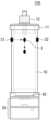
먼저, 도 2는 본 발명의 실시예에 따른 레귤레이터 일체형 점적챔버의 정면도(챔버 커버형)를 도시한 것이다. 그리고 도 3은 본 발명의 실시예에 따른 레귤레이터 일체형 점적챔버의 정면도(스파이크형)를 도시한 것이다.First, Fig. 2 illustrates a front view (chamber cover type) of a regulator-integrated drip chamber according to an embodiment of the present invention. And Fig. 3 illustrates a front view (spike type) of a regulator-integrated drip chamber according to an embodiment of the present invention.
본 발명의 실시예에 따른 점적챔버는, 수액백과 연결되어 수액백의 수액이 공급되는 것으로서, 도 3에 도시된 바와 같이, 수액공(22), 공기공(23), 공기필터(24), 벤트캡(25)을 갖는 스파이크 타입과, 도 2에 도시된 바와 같이, 챔버커버(11)와 수액백과 연결되는 연결커넥터(12)를 갖는 커버 형태로 구성될 수 있음을 알 수 있다. 이하에서는 커버형을 예를 들어 설명하도록 한다. 다만 이러한 형태로 권리범위가 제한되는 것은 아니다.According to an embodiment of the present invention, the drip chamber is connected to an infusion bag to supply the infusion bag's infusion fluid, and as shown in FIG. 3, it can be seen that it can be configured in a spike type having an infusion hole (22), an air hole (23), an air filter (24), and a vent cap (25), and as shown in FIG. 2, in a cover type having a chamber cover (11) and a connection connector (12) connected to the infusion bag. Hereinafter, the cover type will be described as an example. However, the scope of the rights is not limited to such a type.
점적챔버(100)의 몸체부(10)는 수액백(1)에 연결되어 상기 수액백에 저장된 수액이 내부로 물방울 형태로 공급되며, 토출홀이 마련되고 공급호스(2)가 연결되는 하단부를 갖는다.The body part (10) of the drip chamber (100) is connected to a fluid bag (1) so that the fluid stored in the fluid bag is supplied internally in the form of droplets, and has a lower part provided with a discharge hole and to which a supply hose (2) is connected.
그리고 본 발명의 실시예에 따른 점적챔버(100)는 몸체부(10) 하부 일측에 일체로 결합되어 몸체부(10)에서 공급호스(2)로 공급되는 수액의 유량을 조절하는 레귤레이터(50)를 포함하는 것을 특징으로 한다.And the drip chamber (100) according to the embodiment of the present invention is characterized by including a regulator (50) that is integrally connected to one side of the lower part of the body part (10) and controls the flow rate of the liquid supplied from the body part (10) to the supply hose (2).
또한 본 발명의 실시예에 따른 점적챔버(100)는 몸체부(10) 하단 내부 일측에 필터부재가 구비되어 이물질 등을 여과할 수 있으며, 이러한 필터부재(40)는 친수성 멤브레인으로 구성되어 기체(공기)가 공급호스로 유입되는 것을 방지하도록 구성될 수 있다.In addition, the drip chamber (100) according to the embodiment of the present invention is equipped with a filter member on one side of the lower inner portion of the body (10) to filter foreign substances, etc., and this filter member (40) may be configured to be made of a hydrophilic membrane to prevent gas (air) from flowing into the supply hose.
본 발명의 실시예에 따른 레귤레이터(50)는 상단몸체부(51)와, 상기 상단몸체부(51)를 기준으로 회동될 수 있는 하단몸체부(55)를 포함하여 구성될 수 있다.A regulator (50) according to an embodiment of the present invention may be configured to include an upper body part (51) and a lower body part (55) that can rotate around the upper body part (51).
상단몸체부(51)는 점적챔버(100)의 몸체부(10) 하부 일측에 일체로 결합되며, 하단면 일측에 형성되는 배출공(52)과, 하단면 중앙에서 하부측으로 돌출된 중심회전축(53)을 갖는다. 또한 상단몸체부의 내부에는 환자의 안전을 위하여 이물질과 공기주입방지를 위한 필터부재(40)가 장착되어 진다.The upper body part (51) is integrally connected to the lower side of the body part (10) of the drip chamber (100), and has a discharge hole (52) formed on one side of the lower surface, and a central rotation axis (53) protruding downward from the center of the lower surface. In addition, a filter member (40) is installed inside the upper body part to prevent foreign substances and air injection for the safety of the patient.
또한 하단몸체부(55)는 중심회전축(53)이 삽입되는 회전축 도입홈(57)과, 상단면 일측에 형성되는 공급공(56)이 구비된다. 따라서 하단몸체부(55)가 중심회전축(53)으로 회전되면서 수액의 공급량이 조절될 수 있다.In addition, the lower body part (55) is provided with a rotation shaft introduction groove (57) into which a central rotation shaft (53) is inserted, and a supply hole (56) formed on one side of the upper surface. Accordingly, the amount of sap supplied can be adjusted as the lower body part (55) rotates about the central rotation shaft (53).
또한 상단몸체부(51)의 회전중심축(53)의 하단 일측 외면에 삽입홈이 형성되며 하단몸체부(55)의 회전축도입홈을 형성하기 위한 하부 돌출관의 하부 외면에 걸림턱(58)이 형성되어 진다. 따라서 하단몸체부(55)에 연결된 하부돌출관이 상단몸체부(51)의 회전중심축(53)의 중심을 잡아주면서 상단몸체부(51)와 하단몸체부(55)의 분리가 없도록 락장치 역할이 가능해 진다.In addition, an insertion groove is formed on the outer surface of one side of the lower portion of the rotation center axis (53) of the upper body part (51), and a catch (58) is formed on the outer surface of the lower portion of the lower protrusion tube to form a rotation axis introduction groove of the lower body part (55). Accordingly, the lower protrusion tube connected to the lower body part (55) can serve as a locking device to prevent separation of the upper body part (51) and the lower body part (55) by holding the center of the rotation center axis (53) of the upper body part (51).
그리고 상단몸체부(51)와 하단몸체부(55)의 접촉면 사이 공간에 실리콘 재질의 가스켓(59)이 게재되어 상단몸체부(51)와 하단몸체부55)가 중심축을 기준으로 원활한 돌림과 누수방지가 가능해진다.And, a gasket (59) made of silicone is placed in the space between the contact surfaces of the upper body part (51) and the lower body part (55), so that the upper body part (51) and the lower body part (55) can rotate smoothly around the central axis and prevent water leakage.
그리고 후에 상세히 설명되는 바와 같이, 본 발명의 실시예에 따른 레귤레이터(50)는 하단몸체부(55)의 회동을 제한하는 잠금장치(60)를 포함하여 구성될 수 있다.And as will be described in detail later, the regulator (50) according to an embodiment of the present invention may be configured to include a locking device (60) that limits the rotation of the lower body part (55).
도 4는 본 발명의 실시예에 따른 유량측정부를 갖는 레귤레이터 일체형 점적챔버의 정면도(챔버 커버형)를 도시한 것이다. 그리고 도 5a 및 도 5b는 본 발명의 실시예에 따른 유량측정부와 플로팅부재를 갖는 레귤레이터 일체형 점적챔버의 정면도(챔버 커버형)를 도시한 것이다.Fig. 4 is a front view (chamber cover type) of a regulator-integrated drip chamber having a flow rate measuring unit according to an embodiment of the present invention. And Figs. 5a and 5b are front views (chamber cover type) of a regulator-integrated drip chamber having a flow rate measuring unit and a floating member according to an embodiment of the present invention.
본 발명의 실시예에 따른 점적챔버(100)은 몸체부(10) 일측에 설치되어 몸체부(10)로 통과되는 수액방울을 감지하여 공급되는 수액량을 측정하는 유량측정부(30)를 포함하여 구성될 수 있다.The drip chamber (100) according to an embodiment of the present invention may be configured to include a flow rate measuring unit (30) installed on one side of the body part (10) to detect droplets of fluid passing through the body part (10) and measure the amount of fluid supplied.
또한 플로팅부재(70)는 몸체부(10)에 저장된 수액에 부유되며, 공급호스(2)로의 수액공급이 완료되면 토출홀(62)을 폐쇄시키도록 구성된다.In addition, the floating member (70) floats on the sap stored in the body part (10) and is configured to close the discharge hole (62) when the sap supply to the supply hose (2) is completed.
본 발명의 실시예에 따른 유량측정부(30)는 광센서, 적외선센서, 레이저센서 등으로 구성될 수 있으며, 광 등을 조사하는 발광부(31)와 반사된 광을 수광하는 수광부(32)를 포함하여 구성될 수 있다. 이러한 센서를 통해 떨어지는 수액방울을 감지하며, 공급유량연산부(33)는 이러한 측정값을 전송받아 수액방울의 주기 또는, 특정주기 동안 공급된 수액방울의 개수를 기반으로 공급유량과, 공급된 총량을 연산하게 된다.The flow rate measuring unit (30) according to an embodiment of the present invention may be composed of a light sensor, an infrared sensor, a laser sensor, etc., and may be composed of a light emitting unit (31) that irradiates light, etc., and a light receiving unit (32) that receives reflected light. Falling sap drops are detected through this sensor, and the supply flow rate calculation unit (33) receives this measurement value and calculates the supply flow rate and the total amount supplied based on the period of the sap drops or the number of sap drops supplied during a specific period.
도 6은 본 발명의 실시예에 따른 유량측정부와 수위센서와 플로팅부재를 갖는 레귤레이터 일체형 점적챔버의 정면도(챔버 커버형)를 도시한 것이다.FIG. 6 is a front view (chamber cover type) of a regulator-integrated drip chamber having a flow rate measuring unit, a water level sensor, and a floating member according to an embodiment of the present invention.
또한 도 6에 도시된 바와 같이, 본 발명의 실시예에 따른 점적챔버(100)에는, 점적챔버 내의 수액 수위를 측정하는 수위센서(90)를 더 포함하여 구성될 수 있다.In addition, as illustrated in FIG. 6, the drip chamber (100) according to the embodiment of the present invention may further include a water level sensor (90) that measures the liquid level within the drip chamber.
이때 플로팅부재(70)는 반사판의 기능을 수행할 수 있다. 따라서 수위센서는 플로팅부재(70)의 위치를 기반으로 점적챔버(100) 내의 수위를 측정하도록 구성될 수 있다.At this time, the floating member (70) can perform the function of a reflector. Therefore, the water level sensor can be configured to measure the water level within the drip chamber (100) based on the position of the floating member (70).
그리고 수위가 설정된 범위 미만이 되는 경우 알림데이터가 송출되도록 구성될 수 있다.And it can be configured to send out notification data when the water level falls below a set range.
또한 후에 설명되는 바와 같이, 관리서버(110)에는 점적챔버(100)의 수위에 따른 점적챔버(100), 공급호스(2), 카테터(3) 끝단까지의 잔존 수액량을 연산하는 잔존수액연산부(91)를 포함하여 구성될 수 있다.In addition, as described later, the management server (110) may be configured to include a residual fluid calculation unit (91) that calculates the amount of residual fluid up to the tip of the drip chamber (100), supply hose (2), and catheter (3) according to the water level of the drip chamber (100).
따라서 제어부(120)는 공급유량연산부(33)에서 연산된 총공급량에서 잔존수액연산부(91)에서 연산된 잔존수액량을 뺀 값이 설정된 공급량에 도달하면 수액공급을 중단시키도록 유량조절유닛(80)을 제어하게 된다.Accordingly, the control unit (120) controls the flow rate control unit (80) to stop the fluid supply when the value obtained by subtracting the residual fluid amount calculated by the residual fluid calculation unit (91) from the total supply amount calculated by the supply flow rate calculation unit (33) reaches the set supply amount.
즉, 공급호스(2)의 길이와 내경 등에 대한 정보와, 공급호스의 사이즈에 따른 잔존 수액 양이 입력되어 있고, 수위센서(90)에서 점적챔버(100) 내의 수위값을 알면 실시간으로 카테터 부터 점적챔버 내에 잔존하고 있는 수액의 유량을 연산할 수 있다.That is, information about the length and inner diameter of the supply hose (2), the amount of remaining fluid according to the size of the supply hose, etc. are input, and if the water level value in the drip chamber (100) is known from the water level sensor (90), the flow rate of the fluid remaining in the drip chamber from the catheter can be calculated in real time.
수액백(1)에서 점적챔버(100)로 공급된 총 공급유량에서 이러한 잔존 수액양을 빼면, 실제 환자에게 공급된 수액의 양을 연산할 수 있고, 제어부(120)는 이러한 실제 환자에게 공급된 수액의 양을 기반으로 설정된 공급량이 실제 환자에게 공급된 수액의 양에 도달하는 경우 유량제어유닛(80)을 통해 수액공급이 중단되도록 제어하게 된다.By subtracting this remaining amount of fluid from the total amount of fluid supplied from the infusion bag (1) to the drip chamber (100), the amount of fluid actually supplied to the patient can be calculated, and the control unit (120) controls the fluid supply to be stopped through the flow control unit (80) when the set supply amount based on this amount of fluid actually supplied to the patient reaches the amount of fluid actually supplied to the patient.
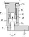
도 7a는 본 발명의 실시예에 따른 잠금장치를 갖는 레귤레이터 일체형 점적챔버의 단면도를 도시한 것이다. 그리고 도 7b는 도 7b에서 하단몸체부가 제외된 상태의 단면도를 도시한 것이다. 도 8은 도 7a에서 잠금장치 부분의 확대도를 도시한 것이다.Fig. 7a is a cross-sectional view of a regulator-integrated drip chamber having a locking device according to an embodiment of the present invention. Fig. 7b is a cross-sectional view of Fig. 7b with the lower body portion removed. Fig. 8 is an enlarged view of the locking device portion of Fig. 7a.
그리고 도 9는 본 발명의 실시예에 따른 잠금장치 몸체 단면도, 잠금부재 중심부재 단면도, 잠금부재 레버 단면도, 평면도를 도시한 것이다.And FIG. 9 illustrates a cross-sectional view of a locking device body, a cross-sectional view of a central member of a locking member, a cross-sectional view of a locking member lever, and a plan view according to an embodiment of the present invention.
또한 도 10a는 본 발명의 실시예에 따른 해제모드시 잠금장치 단면도, 도 10b는 본 발명의 실시예에 따른 잠금모드시 잠금장치 단면도를 도시한 것이다.In addition, FIG. 10a is a cross-sectional view of a locking device in unlock mode according to an embodiment of the present invention, and FIG. 10b is a cross-sectional view of a locking device in lock mode according to an embodiment of the present invention.
도 7a, 도 7b 및 도 8, 도 9, 및 도 10a 및 도 10b에 도시된 바와 같이, 레귤레이터(50)는 하단몸체부(55)의 회동을 제한하는 잠금장치(60)를 포함하여 구성될 수 있음을 알 수 있다.As shown in FIGS. 7a, 7b and 8, 9, and 10a and 10b, it can be seen that the regulator (50) can be configured to include a locking device (60) that limits the rotation of the lower body part (55).
본 발명의 실시예에 따른 잠금장치는, 내부나사산(63)을 갖는 잠금장치 몸체(61)와, 레버와 연결되며 걸림단(65)이 내부나사산(63)과 나사결합되는 중심부재(64)를 포함하여 구성될 수 있다.A locking device according to an embodiment of the present invention may be configured to include a locking device body (61) having an internal screw thread (63), and a central member (64) connected to a lever and having a catch (65) screw-connected with the internal screw thread (63).
먼저, 레귤레이터(50)의 상단몸체부(51)의 중심회전축(53) 하단에는 삽입홈(54)이 형성된다.First, an insertion groove (54) is formed at the bottom of the central rotation axis (53) of the upper body (51) of the regulator (50).
잠금장치 몸체(61)는, 중심회전축(53)과 회전축 도입홈(57) 사이에 게재되며 하단홀(62)와 내면에 내부나사산(63)이 형성된다.The locking device body (61) is placed between the central rotation shaft (53) and the rotation shaft introduction groove (57), and has a lower hole (62) and an internal screw thread (63) formed on the inner surface.
중심부재(64)는 하단홀(62)에 게재되며 외면의 나사산(66)이 내부나사산(63)과 나사결합되는 걸림단(65)을 갖도록 구성된다. 그리고 이러한 중심부재를 회전시키기 위한 레버(67)를 포함한다.The central member (64) is mounted in the lower hole (62) and is configured to have a catch (65) in which the screw threads (66) on the outer surface are screw-connected with the internal screw threads (63). In addition, it includes a lever (67) for rotating the central member.
따라서 해제모드시에는 도 10a에 도시된 바와 같이, 중심부재(64)의 상단이 중심회전축(53)의 삽입홈(54)의 상면과 이격되어 있어 제한없이 하단몸체부(55)의 회동이 가능하다.Therefore, in the release mode, as shown in Fig. 10a, the upper end of the central member (64) is spaced from the upper surface of the insertion groove (54) of the central rotation axis (53), so that the lower body part (55) can rotate without restriction.
잠금모드시, 레버의 작동, 회전시키게 되면, 도 10b에 도시된 바와 같이, 중심부재(64)가 나사에 의해 회전되면서 상부측으로 이동되게 됨을 알 수 있다. 따라서 중심부재(64) 상단이 삽입홈(54)에 억지끼움되어 하단몸체부(55)의 회동을 제한하게 된다.In the locked mode, when the lever is operated and rotated, as shown in Fig. 10b, it can be seen that the central member (64) is rotated by the screw and moves upward. Accordingly, the upper part of the central member (64) is forcibly fitted into the insertion groove (54), thereby restricting the rotation of the lower body part (55).
도 11은 본 발명의 실시예에 따른 레귤레이터 일체형 점적챔버를 포함한 수액세트의 블록도를 도시한 것이다. 그리고 도 12는 본 발명의 실시예에 따른 제어부의 신호흐름을 나타낸 블록도를 도시한 것이다.Fig. 11 is a block diagram of an infusion set including a regulator-integrated drip chamber according to an embodiment of the present invention. Fig. 12 is a block diagram showing a signal flow of a control unit according to an embodiment of the present invention.
본 발명의 실시예에 따른 수액세트(200)는 공급호스(2) 일측에 구비되어 공급유량을 조절하는 유량조절유닛(80)을 포함할 수 있다. 수The sap set (200) according to the embodiment of the present invention may include a flow rate control unit (80) provided on one side of the supply hose (2) to control the supply flow rate.
그리고 관리서버(110)에는 유량측정부(30)에서 측정된 측정값을 전송받아 수액방울의 주기 또는, 특정주기 동안 공급된 수액방울의 개수를 기반으로 공급유량과, 공급된 총량을 연산하는 공급유량연산부(33)를 포함하여 구성될 수 있다. 그리고 설정부는 수액 공급량, 공급속도를 설정하도록 구성되며, 제어부는 이러한 공급유량연산부(33)에서 연산된 측정값과, 설정부(140)에서 설정된 공급속도를 기반으로 유량조절유닛(80)을 제어할 수 있다.And the management server (110) may be configured to include a supply flow rate calculation unit (33) that receives the measured value from the flow rate measurement unit (30) and calculates the supply flow rate and the total amount supplied based on the cycle of the sap droplets or the number of sap drops supplied during a specific cycle. And the setting unit is configured to set the sap supply amount and the supply speed, and the control unit can control the flow rate control unit (80) based on the measured value calculated by the supply flow rate calculation unit (33) and the supply speed set by the setting unit (140).
그리고 제어부(120)는 수액 총공급량이 설정된 공급량에 도달하면 수액공급을 중단시키도록 유량조절유닛(80)을 제어하게 된다.And the control unit (120) controls the flow rate control unit (80) to stop the sap supply when the total sap supply amount reaches the set supply amount.
또한 도 6에 도시된 바와 같이, 본 발명의 실시예에 따른 점적챔버(100)에는, 점적챔버 내의 수액 수위를 측정하는 수위센서(90)를 더 포함하여 구성될 수 있다. 이러한 또한 관리서버(110)에는 점적챔버(100)의 수위에 따른 점적챔버(100), 공급호스(2), 카테터(3) 끝단까지의 잔존 수액량을 연산하는 잔존수액연산부(91)를 포함하여 구성될 수 있다.In addition, as illustrated in FIG. 6, the drip chamber (100) according to the embodiment of the present invention may further include a level sensor (90) that measures the fluid level within the drip chamber. In addition, the management server (110) may include a residual fluid calculation unit (91) that calculates the amount of residual fluid up to the tip of the drip chamber (100), supply hose (2), and catheter (3) according to the fluid level of the drip chamber (100).
따라서 제어부(120)는 공급유량연산부(33)에서 연산된 총공급량에서 잔존수액연산부(91)에서 연산된 잔존수액량을 뺀 값이 설정된 공급량에 도달하면 수액공급을 중단시키도록 유량조절유닛을 제어하게 된다.Accordingly, the control unit (120) controls the flow rate control unit to stop the fluid supply when the value obtained by subtracting the residual fluid amount calculated in the residual fluid calculation unit (91) from the total supply amount calculated in the supply flow rate calculation unit (33) reaches the set supply amount.
즉, 공급호스(2)의 길이와 내경 등에 대한 정보와, 공급호스의 사이즈에 따른 잔존 수액 양이 입력되어 있고, 수위센서(90)에서 점적챔버(100) 내의 수위값을 알면 실시간으로 카테터 부터 점적챔버 내에 잔존하고 있는 수액의 유량을 연산할 수 있다.That is, information about the length and inner diameter of the supply hose (2), the amount of remaining fluid according to the size of the supply hose, etc. are input, and if the water level value in the drip chamber (100) is known from the water level sensor (90), the flow rate of the fluid remaining in the drip chamber from the catheter can be calculated in real time.
수액백(1)에서 점적챔버(100)로 공급된 총 공급유량에서 이러한 잔존 수액양을 빼면, 실제 환자에게 공급된 수액의 양을 연산할 수 있고, 제어부(120)는 이러한 실제 환자에게 공급된 수액의 양을 기반으로 설정된 공급량이 실제 환자에게 공급된 수액의 양에 도달하는 경우 유량제어유닛(80)을 통해 수액공급이 중단되도록 제어하게 된다.By subtracting this remaining amount of fluid from the total amount of fluid supplied from the infusion bag (1) to the drip chamber (100), the amount of fluid actually supplied to the patient can be calculated, and the control unit (120) controls the fluid supply to be stopped through the flow control unit (80) when the set supply amount based on this amount of fluid actually supplied to the patient reaches the amount of fluid actually supplied to the patient.
또한, 상기와 같이 설명된 장치 및 방법은 상기 설명된 실시예들의 구성과 방법이 한정되게 적용될 수 있는 것이 아니라, 상기 실시예들은 다양한 변형이 이루어질 수 있도록 각 실시예들의 전부 또는 일부가 선택적으로 조합되어 구성될 수도 있다.In addition, the devices and methods described above are not limited to the configurations and methods of the embodiments described above, and the embodiments may be configured by selectively combining all or part of the embodiments so that various modifications can be made.
1:수액백
2:공급호스
3:카테터
4:사용자 단말기
5:수액
6:수액방울
10:몸체부
11:챔버커버
12:연결커넥터
21:스파이크 도입부
22:수액공
23:공기공
24:공기필터
25:밴트캡
30:유량측정부
31:발광부
32:수광부
33:공급유량연산부
40:필터부재
50:레귤레이터
51:상단몸체부
52:배출공
53:중심회전축
54:삽입홈
55:하단몸체부
56:공급공
57:회전축 도입홈
58:걸림턱
59:가스켓
60:잠금장치
61:잠금장치 몸체
62:하단홀
63:내부나사산
64:중심부재
65:걸림단
66:나사산
67:레버
70:플로팅부재
80:유량조절유닛
90:수위센서
91:잔존수액연산부
100:레귤레이터 일체형 점적챔버
110:관리서버
120:제어부
130:알림부
140:설정부
141:DB
200:레귤레이터 일체형 점적챔버를 포함한 수액세트1: Sap bag
2: Supply hose
3: Catheter
4: User terminal
5:Sap
6: Sap drop
10: Body
11:Chamber cover
12:Connector
21: Spike Intro
22: Sap pump
23: Air air
24: Air filter
25:Bantcap
30: Flow measurement section
31: Light-emitting part
32: Light receiving section
33: Supply flow calculation section
40: Filter Absence
50:Regulator
51:Upper body
52: Exhaust hole
53:Central rotation axis
54:Insert Home
55: Lower body
56:Supplier
57:Rotation axis introduction home
58:Snag
59:Gasket
60:Lock
61:Lock body
62: Bottom hole
63: Internal screw thread
64:Center Absence
65:Standard
66: Screw
67: Lever
70:Floating member
80: Flow control unit
90: Water level sensor
91: Residual sap calculation section
100: Regulator integrated drip chamber
110: Management Server
120:Control Unit
130: Notification section
140:Settings section
141:DB
200: Infusion set including regulator integrated drip chamber
Claims (7)
Translated fromKorean수액백에 연결되어 상기 수액백에 저장된 수액이 내부로 물방울 형태로 공급되며, 토출홀이 마련되고 공급호스가 연결되는 하단부를 갖는 몸체부; 및
상기 몸체부 하부 일측에 일체로 결합되어 상기 몸체부에서 공급호스로 공급되는 수액의 유량을 조절하는 레귤레이터;를 포함하는 것을 특징으로 하는 레귤레이터 일체형 점적챔버.
As a drip chamber connected to a sap bag and supplying sap from the sap bag,
A body part connected to a sap bag and supplying the sap stored in the sap bag in the form of droplets into the interior, having a discharge hole and a lower part to which a supply hose is connected; and
A regulator-integrated drip chamber characterized by including a regulator that is integrally connected to one side of the lower part of the body and controls the flow rate of the liquid supplied from the body to the supply hose.
상기 몸체부 하단 내부 일측에 구비되는 필터부재를 더 포함하고,
상기 레귤레이터는
상기 몸체부 하부 일측에 일체로 결합되며, 하단면 일측에 형성되는 배출공과, 상기 하단면 중앙에서 하부측으로 돌출된 중심회전축을 갖는 상단몸체부; 및
상기 중심회전축이 삽입되는 회전축 도입홈과, 상단면 일측에 형성되는 공급공이 구비되는 하단몸체부, 상기 상단몸체부와 상기 하단몸체부 사이에 게재되는 가스켓을 포함하고, 상기 하단몸체부가 상기 중심회전축으로 회전되면서 상기 수액의 공급량이 조절되고,
상기 레귤레이터는 상기 하단몸체부의 회동을 제한하는 잠금장치를 갖는 것을 특징으로 하는 레귤레이터 일체형 점적챔버.
In paragraph 1,
It further includes a filter member provided on one side of the lower inner portion of the above body,
The above regulator
An upper body part integrally connected to one side of the lower body part, having a discharge hole formed on one side of the lower surface, and a central rotation axis protruding downward from the center of the lower surface; and
It includes a lower body part having a rotation shaft introduction groove into which the central rotation shaft is inserted, a supply hole formed on one side of the upper surface, and a gasket interposed between the upper body part and the lower body part, and the supply amount of the sap is controlled as the lower body part rotates about the central rotation shaft.
A regulator-integrated drip chamber characterized in that the regulator has a locking device that limits rotation of the lower body part.
상기 잠금장치는,
상기 중심회전축 하단에 형성되는 삽입홈, 상기 중심회전축과 상기 회전축 도입홈 사이에 게재되며 하단홀와 내면에 내부나사산이 형성되는 잠금장치 몸체, 상기 하단홀에 게재되며 외면의 나사산이 상기 내부나사산과 나사결합되는 걸림단을 갖는 중심부재, 및 상기 중심부재를 회전시키기 위한 레버를 포함하여,
잠금모드시, 상기 레버의 작동에 의해 상기 중심부재 상단이 상기 삽입홈에 억지끼움되어 상기 하단몸체부의 회동을 제한하는 것을 특징으로 하는 레귤레이터 일체형 점적챔버.
In the second paragraph,
The above locking device,
Including an insertion groove formed at the bottom of the central rotation shaft, a locking device body that is placed between the central rotation shaft and the rotation shaft introduction groove and has a lower hole and internal screw threads formed on the inner surface, a central member that is placed in the lower hole and has a catch end whose outer screw threads are screw-connected with the internal screw threads, and a lever for rotating the central member.
A regulator-integrated drip chamber characterized in that, in the locked mode, the upper part of the central member is forcibly fitted into the insertion groove by the operation of the lever, thereby limiting the rotation of the lower body part.
상기 몸체부 일측에 설치되어 상기 몸체부로 통과되는 수액방울을 감지하여 공급되는 수액량을 측정하는 유량측정부;
상기 몸체부에 저장된 수액에 부유되며, 공급호스로의 수액공급이 완료되면 상기 토출홀을 폐쇄시키는 플로팅부재; 및
상기 측정값을 전송받아 수액방울의 주기 또는, 특정주기 동안 공급된 수액방울의 개수를 기반으로 공급유량과, 공급된 총량을 연산하는 공급유량연산부;를 포함하고,
상기 유량측정부는, 광센서, 적외선센서, 레이저센서 중 적어도 어느 하나로 구성되어, 공급되는 수액방울을 측정하는 것을 특징으로 하는 레귤레이터 일체형 점적챔버.
In paragraph 1,
A flow measurement unit installed on one side of the body to detect sap droplets passing through the body and measure the amount of sap supplied;
A floating member that floats on the sap stored in the above body part and closes the discharge hole when the sap supply to the supply hose is completed; and
It includes a supply flow rate calculation unit that receives the above measurement value and calculates the supply flow rate and the total amount supplied based on the cycle of the sap droplets or the number of sap drops supplied during a specific cycle;
A regulator-integrated drip chamber characterized in that the above flow measurement unit is configured with at least one of a light sensor, an infrared sensor, and a laser sensor to measure the supplied fluid droplets.
상기 공급호스 일측에 구비되어 공급유량을 조절하는 유량조절유닛; 및
유량측정부에서 측정된 측정값을 전송받아 수액방울의 주기 또는, 특정주기 동안 공급된 수액방울의 개수를 기반으로 공급유량과, 공급된 총량을 연산하는 공급유량연산부를 갖는 관리서버;를 포함하는 것을 특징으로 하는 레귤레이터 일체형 점적챔버를 포함한 수액세트.
An infusion set having an infusion chamber, a supply hose, and a catheter according to any one of claims 1 to 4,
A flow rate control unit provided on one side of the above supply hose to control the supply flow rate; and
An infusion set including a regulator-integrated drip chamber, characterized by including a management server having a supply flow rate calculation unit that receives a measurement value measured from a flow rate measurement unit and calculates the supply flow rate and the total amount supplied based on the cycle of the infusion droplets or the number of infusion droplets supplied during a specific cycle.
수액 공급량, 공급속도를 설정하는 설정부; 및
상기 측정값과, 설정된 공급속도를 기반으로 상기 유량조절유닛을 제어하고, 수액 총공급량이 설정된 공급량에 도달하면 수액공급을 중단시키도록 유량조절유닛을 제어하는 제어부;를 포함하는 것을 특징으로 하는 레귤레이터 일체형 점적챔버를 포함한 수액세트.
In paragraph 5,
A setting section for setting the amount and speed of sap supply; and
An infusion set including a regulator-integrated drip chamber, characterized in that it includes a control unit that controls the flow rate control unit based on the above measurement value and the set supply speed, and controls the flow rate control unit to stop the supply of the infusion when the total supply amount of the infusion reaches the set supply amount.
상기 점적챔버 내의 수액 수위를 측정하는 수위센서; 및
점적챔버의 수위에 따른 점적챔버, 공급호스, 카테터 끝단까지의 잔존 수액량을 연산하는 잔존수액연산부;를 포함하고,
상기 제어부는 상기 총공급량에서 상기 잔존수액량을 뺀 값이 상기 설정된 공급량에 도달하면 수액공급을 중단시키도록 유량조절유닛을 제어하는 것을 특징으로 하는 레귤레이터 일체형 점적챔버를 포함한 수액세트.
In paragraph 6,
A water level sensor for measuring the liquid level within the above drip chamber; and
Includes a residual fluid calculation unit that calculates the amount of residual fluid up to the tip of the drip chamber, supply hose, and catheter according to the water level of the drip chamber;
An infusion set including a regulator-integrated drip chamber, characterized in that the control unit controls the flow rate control unit to stop the infusion supply when the value obtained by subtracting the remaining infusion amount from the total supply amount reaches the set supply amount.
Priority Applications (1)
| Application Number | Priority Date | Filing Date | Title |
|---|---|---|---|
| KR1020230101906AKR20250021215A (en) | 2023-08-04 | 2023-08-04 | Regulatorintegrated drip chamber and infusion set including the same |
Applications Claiming Priority (1)
| Application Number | Priority Date | Filing Date | Title |
|---|---|---|---|
| KR1020230101906AKR20250021215A (en) | 2023-08-04 | 2023-08-04 | Regulatorintegrated drip chamber and infusion set including the same |
Publications (1)
| Publication Number | Publication Date |
|---|---|
| KR20250021215Atrue KR20250021215A (en) | 2025-02-12 |
Family
ID=94629345
Family Applications (1)
| Application Number | Title | Priority Date | Filing Date |
|---|---|---|---|
| KR1020230101906APendingKR20250021215A (en) | 2023-08-04 | 2023-08-04 | Regulatorintegrated drip chamber and infusion set including the same |
Country Status (1)
| Country | Link |
|---|---|
| KR (1) | KR20250021215A (en) |
Citations (2)
| Publication number | Priority date | Publication date | Assignee | Title |
|---|---|---|---|---|
| KR100792805B1 (en) | 2007-01-24 | 2008-01-14 | 사단법인 삼성생명공익재단삼성서울병원 | Liquid level detector of the fluid dosing set |
| KR101027081B1 (en) | 2009-08-18 | 2011-04-05 | 김우진 | Blood backflow prevention device of infusion set |
- 2023
- 2023-08-04KRKR1020230101906Apatent/KR20250021215A/enactivePending
Patent Citations (2)
| Publication number | Priority date | Publication date | Assignee | Title |
|---|---|---|---|---|
| KR100792805B1 (en) | 2007-01-24 | 2008-01-14 | 사단법인 삼성생명공익재단삼성서울병원 | Liquid level detector of the fluid dosing set |
| KR101027081B1 (en) | 2009-08-18 | 2011-04-05 | 김우진 | Blood backflow prevention device of infusion set |
Similar Documents
| Publication | Publication Date | Title |
|---|---|---|
| JP3124766B2 (en) | Patient side occlusion detection system for drug injection system | |
| JP6712221B2 (en) | Fluid control system and disposable assembly | |
| US7327273B2 (en) | Fluid monitoring device | |
| US8287724B2 (en) | Dialysis fluid measurement systems using conductive contacts | |
| CN110087712B (en) | System and method for controlling infusion pump | |
| US9726167B2 (en) | Methods, circuits, devices, apparatuses, encasements and systems for identifying if a medical infusion system is decalibrated | |
| US8067760B2 (en) | Impulse analysis for flow sensor-based fluid control system | |
| JP2732534B2 (en) | Container side blockage detection system for drug injection system | |
| JP4818933B2 (en) | Improvement of drug administration safety for secondary injection | |
| US8016790B2 (en) | Infusion status indicator | |
| CN1674957B (en) | Fluid control device | |
| US20090007642A1 (en) | Dialysis fluid measurement method and apparatus using conductive contacts | |
| JPH024379A (en) | Cassette loading and retaining apparatus for chemical injection system | |
| KR102692339B1 (en) | Regulatorintegrated drip chamber with locking device and infusion set including the same | |
| KR20170034994A (en) | Apparatus for sensing bubble of satety intravenous infusion | |
| JPH05317421A (en) | Multiple injection device | |
| US7639151B2 (en) | Liquid blocking apparatus and system equipped with an alarm or wireless calling device and a storing bag | |
| KR20250021215A (en) | Regulatorintegrated drip chamber and infusion set including the same | |
| JP2020524068A (en) | Priming valve that induces moderate pressure and flow distribution and improves sensor readiness | |
| KR101686031B1 (en) | System for drug injection | |
| US7318819B2 (en) | Automatic locking valve for medication injection | |
| KR20250014148A (en) | Drip chamber with air blocking and flow measurement function and infusion set including the same | |
| KR20070019383A (en) | Ringer's fluid administration status monitoring method and monitoring method | |
| CN212262059U (en) | Disposable infusion set that automatically stops infusion | |
| JP3184831B2 (en) | A device for simultaneous simultaneous administration of multiple infusions or drug solutions |
Legal Events
| Date | Code | Title | Description |
|---|---|---|---|
| PA0109 | Patent application | Patent event code:PA01091R01D Comment text:Patent Application Patent event date:20230804 | |
| PA0201 | Request for examination | Patent event code:PA02011R01I Patent event date:20230804 Comment text:Patent Application | |
| PG1501 | Laying open of application | ||
| E902 | Notification of reason for refusal | ||
| PE0902 | Notice of grounds for rejection | Comment text:Notification of reason for refusal Patent event date:20250527 Patent event code:PE09021S01D |