KR20250011660A - Self-aligned vertical bitlines for three-dimensional (3D) dynamic random access memory (DRAM) devices - Google Patents
Self-aligned vertical bitlines for three-dimensional (3D) dynamic random access memory (DRAM) devicesDownload PDFInfo
- Publication number
- KR20250011660A KR20250011660AKR1020247041820AKR20247041820AKR20250011660AKR 20250011660 AKR20250011660 AKR 20250011660AKR 1020247041820 AKR1020247041820 AKR 1020247041820AKR 20247041820 AKR20247041820 AKR 20247041820AKR 20250011660 AKR20250011660 AKR 20250011660A
- Authority
- KR
- South Korea
- Prior art keywords
- semiconductor
- metal
- bit line
- article
- memory levels
- Prior art date
- Legal status (The legal status is an assumption and is not a legal conclusion. Google has not performed a legal analysis and makes no representation as to the accuracy of the status listed.)
- Pending
Links
Images


Classifications
- H—ELECTRICITY
- H10—SEMICONDUCTOR DEVICES; ELECTRIC SOLID-STATE DEVICES NOT OTHERWISE PROVIDED FOR
- H10B—ELECTRONIC MEMORY DEVICES
- H10B12/00—Dynamic random access memory [DRAM] devices
- H10B12/30—DRAM devices comprising one-transistor - one-capacitor [1T-1C] memory cells
- H10B12/48—Data lines or contacts therefor
- H10B12/482—Bit lines
- H—ELECTRICITY
- H01—ELECTRIC ELEMENTS
- H01L—SEMICONDUCTOR DEVICES NOT COVERED BY CLASS H10
- H01L25/00—Assemblies consisting of a plurality of semiconductor or other solid state devices
- H01L25/03—Assemblies consisting of a plurality of semiconductor or other solid state devices all the devices being of a type provided for in a single subclass of subclasses H10B, H10D, H10F, H10H, H10K or H10N, e.g. assemblies of rectifier diodes
- H01L25/04—Assemblies consisting of a plurality of semiconductor or other solid state devices all the devices being of a type provided for in a single subclass of subclasses H10B, H10D, H10F, H10H, H10K or H10N, e.g. assemblies of rectifier diodes the devices not having separate containers
- H01L25/065—Assemblies consisting of a plurality of semiconductor or other solid state devices all the devices being of a type provided for in a single subclass of subclasses H10B, H10D, H10F, H10H, H10K or H10N, e.g. assemblies of rectifier diodes the devices not having separate containers the devices being of a type provided for in group H10D89/00
- H01L25/0657—Stacked arrangements of devices
- H—ELECTRICITY
- H10—SEMICONDUCTOR DEVICES; ELECTRIC SOLID-STATE DEVICES NOT OTHERWISE PROVIDED FOR
- H10B—ELECTRONIC MEMORY DEVICES
- H10B12/00—Dynamic random access memory [DRAM] devices
- H10B12/01—Manufacture or treatment
- H10B12/02—Manufacture or treatment for one transistor one-capacitor [1T-1C] memory cells
- H—ELECTRICITY
- H10—SEMICONDUCTOR DEVICES; ELECTRIC SOLID-STATE DEVICES NOT OTHERWISE PROVIDED FOR
- H10B—ELECTRONIC MEMORY DEVICES
- H10B12/00—Dynamic random access memory [DRAM] devices
- H10B12/30—DRAM devices comprising one-transistor - one-capacitor [1T-1C] memory cells
- H10B12/48—Data lines or contacts therefor
- H10B12/488—Word lines
- H—ELECTRICITY
- H10—SEMICONDUCTOR DEVICES; ELECTRIC SOLID-STATE DEVICES NOT OTHERWISE PROVIDED FOR
- H10B—ELECTRONIC MEMORY DEVICES
- H10B80/00—Assemblies of multiple devices comprising at least one memory device covered by this subclass
Landscapes
- Engineering & Computer Science (AREA)
- Manufacturing & Machinery (AREA)
- Power Engineering (AREA)
- Microelectronics & Electronic Packaging (AREA)
- Physics & Mathematics (AREA)
- Condensed Matter Physics & Semiconductors (AREA)
- General Physics & Mathematics (AREA)
- Computer Hardware Design (AREA)
- Semiconductor Memories (AREA)
- Internal Circuitry In Semiconductor Integrated Circuit Devices (AREA)
- Electrodes Of Semiconductors (AREA)
Abstract
Translated fromKorean
Description
Translated fromKorean본원에서 설명된 실시예들은 일반적으로 반도체 디바이스 제조에 관한 것으로, 더 상세하게는, 3차원 동적 랜덤 액세스 메모리 디바이스들에 수직 비트 라인들을 형성하는 시스템들 및 방법들에 관한 것이다.Embodiments described herein relate generally to semiconductor device manufacturing, and more particularly, to systems and methods for forming vertical bit lines in three-dimensional dynamic random access memory devices.
3차원(3D) 동적 랜덤 액세스 메모리(DRAM) 디바이스들은 그들의 3차원(3D) 설계들 및 작은 크기들로 인해 제조가능성에 있어서 난제들을 제기한다. 각각이 전계 효과 트랜지스터(FET) 디바이스를 포함하는 개별 메모리 셀들은 FET 디바이스의 소스/드레인 구역들에서 비트 라인에 연결될 필요가 있다. 그러한 비트 라인들의 제조는 전형적으로, 가시선(line-of-sight) 처리, 및 비트 라인들을 위한 슬롯들을 형성하기 위한 고종횡비(HAR) 식각 프로세스를 포함하는 다수의 프로세스 단계들을 요구한다. 예컨대, 3D DRAM 디바이스는 규소(Si) 및 규소 게르마늄(SiGe)의 교번하는 층들을 포함할 수 있으며, 여기서, 규소 게르마늄(SiGe) 층들은 선택적으로 함몰된다. 수직 비트 라인들은 규소(Si) 층들을 통해 HAR 슬롯들을 다결정질 규소(폴리-Si)로 충전(fill)함으로써 형성될 수 있다. 3D DRAM 디바이스에서 수직 비트 라인들을 형성하기 위한 이러한 종래의 접근법은 결과적인 수직 비트 라인들에 공극들을 초래하며, 이는, 비교적 높은 기생 저항으로 이어진다.Three-dimensional (3D) dynamic random access memory (DRAM) devices present manufacturability challenges due to their three-dimensional (3D) designs and small sizes. Individual memory cells, each comprising a field-effect transistor (FET) device, need to be connected to bit lines in the source/drain regions of the FET device. Fabrication of such bit lines typically requires multiple process steps, including line-of-sight processing and a high aspect ratio (HAR) etch process to form slots for the bit lines. For example, a 3D DRAM device may include alternating layers of silicon (Si) and silicon germanium (SiGe), wherein the SiGe layers are selectively recessed. Vertical bit lines may be formed by filling the HAR slots through the silicon (Si) layers with polycrystalline silicon (poly-Si). This conventional approach to forming vertical bit lines in 3D DRAM devices introduces voids in the resulting vertical bit lines, which leads to relatively high parasitic resistance.
그에 따라, 감소된 처리 단계들에 의해 기생 저항이 최소화되게 3D DRAM 디바이스에 수직 비트 라인들을 제조할 수 있는 시스템들 및 방법들에 대한 필요성이 존재한다.Accordingly, there is a need for systems and methods capable of manufacturing vertical bit lines in 3D DRAM devices with minimized parasitic resistance by reducing processing steps.
본 개시내용의 실시예들은 반도체 구조를 제공한다. 반도체 구조는, 제1 방향으로 적층되는 복수의 메모리 레벨들 ― 복수의 메모리 레벨들 각각은, 반도체 층, 워드 라인 금속 층, 및 반도체 층의 단면 상의 인터페이스를 포함함 ―, 제1 방향에서의 복수의 메모리 레벨들의 인접한 메모리 레벨들 사이의 스페이서, 및 복수의 메모리 레벨들 각각의 인터페이스와 접촉하는 비트 라인을 포함하며, 비트 라인은 제1 방향으로 연장된다. 비트 라인은 금속 물질을 포함하고, 인터페이스는 실리사이드를 포함한다.Embodiments of the present disclosure provide a semiconductor structure. The semiconductor structure includes a plurality of memory levels stacked in a first direction, each of the plurality of memory levels including a semiconductor layer, a word line metal layer, and an interface on a cross-section of the semiconductor layer, a spacer between adjacent memory levels of the plurality of memory levels in the first direction, and a bit line contacting the interface of each of the plurality of memory levels, the bit line extending in the first direction. The bit line includes a metal material, and the interface includes silicide.
본 개시내용의 실시예들은 또한, 반도체 디바이스에서 금속 비트 라인을 형성하는 방법을 제공한다. 방법은, 트렌치의 측벽 상에 선택적으로 금속 실리사이드 층을 형성하기 위해 제1 선택적 증착 프로세스를 수행하는 단계 ― 트렌치의 측벽은 제1 방향으로 적층된 복수의 반도체 층들 각각의 제1 단면, 및 복수의 반도체 층들의 인접한 반도체 층들 사이에 배치되는 스페이서의 제2 단면을 포함함 ―, 트렌치의 측벽 상에 선택적으로 금속 층을 형성하기 위해 제2 선택적 증착 프로세스를 수행하는 단계, 및 충전 프로세스를 수행하는 단계를 포함하며, 충전 프로세스는 트렌치 내에 유전체 물질을 증착하는 것을 포함한다. 트렌치의 측벽 상의 금속 층은 복수의 반도체 층들에 걸쳐 연속적이고, 금속 비트 라인을 형성한다.Embodiments of the present disclosure also provide a method of forming a metal bit line in a semiconductor device. The method includes performing a first selective deposition process to selectively form a metal silicide layer on sidewalls of a trench, wherein the sidewalls of the trench include a first cross-section of each of a plurality of semiconductor layers stacked in a first direction and a second cross-section of a spacer disposed between adjacent semiconductor layers of the plurality of semiconductor layers, performing a second selective deposition process to selectively form a metal layer on the sidewalls of the trench, and performing a fill process, wherein the fill process includes depositing a dielectric material within the trench. The metal layer on the sidewalls of the trench is continuous across the plurality of semiconductor layers and forms a metal bit line.
본 개시내용의 실시예들은 추가로, 3차원(3D) 동적 랜덤 액세스 메모리(DRAM) 디바이스를 제공한다. 3D DRAM 디바이스, 제1 방향으로 적층되는 복수의 메모리 레벨들 ― 복수의 메모리 레벨들 각각은, 제1 방향에 직교하는 제2 방향에서의 제1 단부 및 제2 단부를 갖는 반도체 층, 워드 라인 금속 층, 및 반도체 층의 제1 단부에서의 단면 상의 인터페이스를 포함함 ―, 제1 방향에서의 복수의 메모리 레벨들의 인접한 메모리 레벨들 사이의 스페이서, 및 복수의 메모리 레벨들 각각의 인터페이스와 접촉하는 비트 라인을 포함하며, 비트 라인은 제1 방향으로 연장된다. 비트 라인은 금속 물질을 포함하고, 인터페이스는 실리사이드를 포함한다.Embodiments of the present disclosure further provide a three-dimensional (3D) dynamic random access memory (DRAM) device. The 3D DRAM device includes a plurality of memory levels stacked in a first direction, each of the plurality of memory levels including a semiconductor layer having a first end and a second end in a second direction orthogonal to the first direction, a word line metal layer, and an interface in a cross-section at the first end of the semiconductor layer, a spacer between adjacent memory levels of the plurality of memory levels in the first direction, and a bit line contacting the interface of each of the plurality of memory levels, the bit line extending in the first direction. The bit line includes a metal material, and the interface includes silicide.
본 개시내용의 상기 언급된 특징들이 상세하게 이해될 수 있는 방식으로, 위에서 간략하게 요약된 본 개시내용의 보다 구체적인 설명이 실시예들을 참조하여 이루어질 수 있으며, 이러한 실시예들 중 일부가 첨부된 도면들에 예시되어 있다. 그러나, 첨부된 도면들은 본 개시내용의 단지 전형적인 실시예들을 예시하는 것이므로 본 개시내용의 범위를 제한하는 것으로 간주되어서는 안 된다는 것이 유의되어야 하는데, 이는 본 개시내용이 다른 동등하게 유효한 실시예들을 허용할 수 있기 때문이다.
도 1은 일 실시예에 따른 예시적인 다중-챔버 처리 시스템의 개략적인 평면도이다.
도 2a는 일 실시예에 따른 동적 랜덤 액세스 메모리(DRAM) 셀들의 3차원(3D) 메모리 셀 어레이의 일부분의 개략도이다. 도 2b는 DRAM 셀의 개략도이다.
도 3a는 일 실시예에 따른 반도체 구조의 등각도이다. 도 3b, 도 3c, 도 3d, 및 도 3e는, 도 3a에 도시된 반도체 구조의 단면도들이다.
도 4는 일 실시예에 따른, 반도체 구조에 접촉 트렌치 구조를 형성하는 방법의 프로세스 흐름도를 묘사한다.
도 5a, 도 5b, 도 5c, 도 5d, 및 도 5e는 일 실시예에 따른 반도체 구조의 일부분의 단면도들이다.
이해를 용이하게 하기 위해서, 도면들에 공통된 동일한 요소들을 지정하기 위해 가능한 경우 동일한 참조 번호들이 사용되었다. 일 실시예의 요소들 및 특징들은 추가적인 언급이 없이도 다른 실시예들에 유익하게 포함될 수 있는 것으로 고려된다. 도면들 및 다음의 설명에서, X 축, Y 축, 및 Z 축을 포함하는 직교 좌표계가 사용된다. 도면에서 화살표들로 표현된 방향들은 편의상 양의 방향들인 것으로 가정된다.So that the above-mentioned features of the present disclosure may be understood in detail, a more particular description of the present disclosure, briefly summarized above, may be had by reference to embodiments, some of which are illustrated in the appended drawings. It is to be noted, however, that the appended drawings illustrate only typical embodiments of the present disclosure and are therefore not to be considered limiting the scope of the present disclosure, for the present disclosure may admit to other equally effective embodiments.
FIG. 1 is a schematic plan view of an exemplary multi-chamber processing system according to one embodiment.
FIG. 2a is a schematic diagram of a portion of a three-dimensional (3D) memory cell array of dynamic random access memory (DRAM) cells according to one embodiment. FIG. 2b is a schematic diagram of a DRAM cell.
FIG. 3a is an isometric view of a semiconductor structure according to one embodiment. FIGS. 3b, 3c, 3d, and 3e are cross-sectional views of the semiconductor structure illustrated in FIG. 3a.
FIG. 4 depicts a process flow diagram of a method of forming a contact trench structure in a semiconductor structure, according to one embodiment.
FIGS. 5A, 5B, 5C, 5D, and 5E are cross-sectional views of a portion of a semiconductor structure according to one embodiment.
To facilitate understanding, identical reference numerals have been used, where possible, to designate identical elements that are common to the drawings. It is contemplated that elements and features of one embodiment may be beneficially incorporated into other embodiments without further recitation. In the drawings and the following description, an orthogonal coordinate system including an X-axis, a Y-axis, and a Z-axis is used. Directions represented by arrows in the drawings are assumed to be positive directions for convenience.
본원에서 설명된 실시예들은, 극도로 스케일링된 프로세스 노드들을 위한 트랜지스터 디바이스들, 이를테면, 수직 금속 비트 라인들, 및 메모리 셀을 형성하는 FET 디바이스와 수직 비트 라인들 사이의 인터페이스들을 갖는 3D DRAM 디바이스들을 형성하기 위한 시스템들 및 방법들을 제공한다. 수직 비트 라인들은 금속, 이를테면 몰리브데넘(Mo)으로 형성되며, 이는, 다결정질 규소 비트 라인과 비교하여 비트 라인들의 저항을 감소시킨다. 인터페이스들은, 선택적 자기-정렬 증착 프로세스에 의해 금속 실리사이드, 이를테면 몰리브데넘 실리사이드(MoSi2, MoSi, Mo2Si)로 형성되고, FET 디바이스와 수직 비트 라인들 사이의 옴 접촉을 제공하며, 이는 접촉 기생 저항을 감소시킨다.Embodiments described herein provide systems and methods for forming 3D DRAM devices having transistor devices for extremely scaled process nodes, such as vertical metal bit lines, and interfaces between the vertical bit lines and the FET device forming the memory cell. The vertical bit lines are formed of a metal, such as molybdenum (Mo), which reduces the resistance of the bit lines compared to polycrystalline silicon bit lines. The interfaces are formed of a metal silicide, such as molybdenum silicide (MoSi2 , MoSi, Mo2 Si), by a selective self-aligned deposition process and provide an ohmic contact between the FET device and the vertical bit lines, which reduces contact parasitic resistance.
도 1은 본 개시내용의 일부 예들에 따른 다중-챔버 처리 시스템(100)의 예의 개략적인 평면도이다. 처리 시스템(100)은 일반적으로, 팩토리 인터페이스(102), 로드 록 챔버들(104, 106), 개개의 이송 로봇들(112, 114)을 갖는 이송 챔버들(108, 110), 홀딩 챔버들(116, 118), 및 처리 챔버들(120, 122, 124, 126, 128, 130)을 포함한다. 본원에서 상세히 설명되는 바와 같이, 처리 시스템(100) 내의 웨이퍼들은, 웨이퍼들을 처리 시스템(100) 외부의 주변 환경(예컨대, 이를테면 팹(fab)에 존재할 수 있는 대기 주변 환경)에 노출시킴이 없이 다양한 챔버들에서 처리되고 그 챔버들 사이에서 이송될 수 있다. 예컨대, 웨이퍼들은, 처리 시스템(100) 내의 웨이퍼들에 대해 수행되는 다양한 프로세스들 사이에서, 저압(예컨대, 약 300 Torr 이하) 또는 진공 환경의 다양한 챔버들에서 처리되고, 그 저압 또는 진공 환경을 깨뜨림이 없이 그 다양한 챔버들 사이에서 이송될 수 있다. 이에 따라서, 처리 시스템(100)은 웨이퍼들의 일부 처리에 대한 통합 솔루션을 제공할 수 있다.FIG. 1 is a schematic plan view of an example of a multi-chamber processing system (100) according to some examples of the present disclosure. The processing system (100) generally includes a factory interface (102), load lock chambers (104, 106), transfer chambers (108, 110) having individual transfer robots (112, 114), holding chambers (116, 118), and processing chambers (120, 122, 124, 126, 128, 130). As described in detail herein, wafers within the processing system (100) can be processed in and transferred between the various chambers without exposing the wafers to an ambient environment outside the processing system (100), such as an atmospheric ambient environment that may be present in a fab. For example, wafers may be processed in various chambers in low pressure (e.g., less than about 300 Torr) or vacuum environments between various processes performed on the wafers within the processing system (100), and may be transferred between the various chambers without breaking the low pressure or vacuum environment. Accordingly, the processing system (100) may provide an integrated solution for some processing of wafers.
본원에서 제공되는 교시들에 따라 적합하게 수정될 수 있는 처리 시스템의 예들은, 캘리포니아주 산타 클라라에 위치한 어플라이드 머티어리얼스, 인코포레이티드(Applied Materials, Inc.)로부터 상업적으로 입수가능한, 엔듀라(Endura®), 프로듀서(Producer®), 또는 센츄라(Centura®) 통합 처리 시스템들 또는 다른 적합한 처리 시스템들을 포함한다. (다른 제조자들로부터의 처리 시스템들을 포함하는) 다른 처리 시스템들이 본원에서 설명된 양상들로부터 이익을 얻도록 적응될 수 있는 것으로 고려된다.Examples of processing systems that may be suitably modified in accordance with the teachings provided herein includethe Endura®,Producer® , orCentura® integrated processing systems, commercially available from Applied Materials, Inc., located in Santa Clara, Calif., or other suitable processing systems. It is contemplated that other processing systems (including processing systems from other manufacturers) may be adapted to benefit from the aspects described herein.
도 1의 예시된 예에서, 팩토리 인터페이스(102)는 웨이퍼들의 이송을 용이하게 하기 위해 도킹 스테이션(140) 및 팩토리 인터페이스 로봇들(142)을 포함한다. 도킹 스테이션(140)은 하나 이상의 전방 개방 통합 포드(front opening unified pod)(FOUP)(144)를 수용하도록 구성된다. 일부 예들에서, 각각의 팩토리 인터페이스 로봇(142)은 일반적으로, 웨이퍼들을 팩토리 인터페이스(102)로부터 로드 록 챔버들(104, 106)로 이송하도록 구성되는 개개의 팩토리 인터페이스 로봇(142)의 하나의 단부 상에 배치되는 블레이드(148)를 포함한다.In the illustrated example of FIG. 1, the factory interface (102) includes a docking station (140) and factory interface robots (142) to facilitate transfer of wafers. The docking station (140) is configured to receive one or more front opening unified pods (FOUPs) (144). In some examples, each factory interface robot (142) generally includes a blade (148) disposed on one end of the individual factory interface robots (142) that is configured to transfer wafers from the factory interface (102) to the load lock chambers (104, 106).
로드 록 챔버들(104, 106)은, 팩토리 인터페이스(102)에 결합되는 개개의 포트들(150, 152) 및 이송 챔버(108)에 결합되는 개개의 포트들(154, 156)을 갖는다. 이송 챔버(108)는 추가로, 홀딩 챔버들(116, 118)에 결합되는 개개의 포트들(158, 160) 및 처리 챔버들(120, 122)에 결합되는 개개의 포트들(162, 164)을 갖는다. 유사하게, 이송 챔버(110)는, 홀딩 챔버들(116, 118)에 결합되는 개개의 포트들(166, 168) 및 처리 챔버들(124, 126, 128, 130)에 결합되는 개개의 포트들(170, 172, 174, 176)을 갖는다. 포트들(154, 156, 158, 160, 162, 164, 166, 168, 170, 172, 174, 176)은, 예컨대, 이송 로봇들(112, 114)에 의해 자신을 통해 웨이퍼들을 통과시키고, 가스가 개개의 챔버들 사이를 통과하는 것을 방지하기 위해 개개의 챔버들 사이에 밀봉을 제공하기 위한, 슬릿 밸브들을 갖는 슬릿 밸브 개구들일 수 있다. 일반적으로, 임의의 포트는 그 포트를 통해 웨이퍼를 이송하기 위해 개방된다. 그렇지 않으면, 포트는 폐쇄된다.The load lock chambers (104, 106) have individual ports (150, 152) that couple to the factory interface (102) and individual ports (154, 156) that couple to the transfer chamber (108). The transfer chamber (108) additionally has individual ports (158, 160) that couple to the holding chambers (116, 118) and individual ports (162, 164) that couple to the processing chambers (120, 122). Similarly, the transfer chamber (110) has individual ports (166, 168) that couple to the holding chambers (116, 118) and individual ports (170, 172, 174, 176) that couple to the processing chambers (124, 126, 128, 130). The ports (154, 156, 158, 160, 162, 164, 166, 168, 170, 172, 174, 176) may be slit valve openings having slit valves to allow wafers to pass therethrough, for example, by transfer robots (112, 114), and to provide a seal between the individual chambers to prevent gas from passing between the individual chambers. Typically, any port is open to transfer a wafer therethrough. Otherwise, the port is closed.
로드 록 챔버들(104, 106), 이송 챔버들(108, 110), 홀딩 챔버들(116, 118), 및 처리 챔버들(120, 122, 124, 126, 128, 130)은 가스 및 압력 제어 시스템(구체적으로 예시되지 않음)에 유체유동가능하게(fluidly) 결합될 수 있다. 가스 및 압력 제어 시스템은, 하나 이상의 가스 펌프(예컨대, 터보 펌프들, 크라이오 펌프(cryo-pump)들, 러핑 펌프(roughing pump)들), 가스 소스들, 다양한 밸브들, 및 다양한 챔버들에 유체유동가능하게 결합되는 도관들을 포함할 수 있다. 동작 시, 팩토리 인터페이스 로봇(142)이 웨이퍼를 FOUP(144)로부터 포트(150 또는 152)를 통해 로드 록 챔버(104 또는 106)로 이송한다. 이어서, 가스 및 압력 제어 시스템은 로드 록 챔버(104 또는 106)를 펌핑 다운한다. 가스 및 압력 제어 시스템은 추가로, 이송 챔버들(108, 110) 및 홀딩 챔버들(116, 118)을, 내부가 저압 또는 진공 환경(불활성 가스를 포함할 수 있음)이게 유지한다. 그러므로, 로드 록 챔버(104 또는 106)의 펌핑 다운은, 예컨대, 팩토리 인터페이스(102)의 대기 환경과 이송 챔버(108)의 저압 또는 진공 환경 사이에서 웨이퍼를 전달하는 것을 용이하게 한다.The load lock chambers (104, 106), transfer chambers (108, 110), holding chambers (116, 118), and treatment chambers (120, 122, 124, 126, 128, 130) may be fluidly coupled to a gas and pressure control system (not specifically illustrated). The gas and pressure control system may include one or more gas pumps (e.g., turbo pumps, cryo-pumps, roughing pumps), gas sources, various valves, and conduits fluidly coupled to the various chambers. In operation, a factory interface robot (142) transfers a wafer from a FOUP (144) through a port (150 or 152) into the load lock chamber (104 or 106). The gas and pressure control system then pumps down the load lock chamber (104 or 106). The gas and pressure control system additionally maintains the transfer chambers (108, 110) and the holding chambers (116, 118) within a low pressure or vacuum environment (which may include an inert gas). Thus, pumping down the load lock chamber (104 or 106) facilitates transferring wafers between, for example, the atmospheric environment of the factory interface (102) and the low pressure or vacuum environment of the transfer chamber (108).
펌핑 다운된 로드 록 챔버(104 또는 106) 내에 웨이퍼가 있는 상태에서, 이송 로봇(112)은 웨이퍼를 로드 록 챔버(104 또는 106)로부터 포트(154 또는 156)를 통해 이송 챔버(108) 내로 이송한다. 이어서, 이송 로봇(112)은, 웨이퍼를, 처리를 위해 개개의 포트들(162, 164)을 통해 처리 챔버들(120, 122) 중 임의의 처리 챔버로 그리고 추가적인 이송을 대기하도록 홀딩하기 위해 개개의 포트들(158, 160)을 통해 홀딩 챔버들(116, 118)로 이송하고/거나 그 임의의 처리 챔버와 그 홀딩 챔버들 사이에서 이송하는 것이 가능하다. 유사하게, 이송 로봇(114)은 포트(166 또는 168)를 통해 홀딩 챔버(116 또는 118) 내의 웨이퍼에 액세스하는 것이 가능하며, 웨이퍼를, 처리를 위해 개개의 포트들(170, 172, 174, 176)을 통해 처리 챔버들(124, 126, 128, 130) 중 임의의 처리 챔버로 그리고 추가적인 이송을 대기하도록 홀딩하기 위해 개개의 포트들(166, 168)을 통해 홀딩 챔버들(116, 118)로 이송하고/거나 그 임의의 처리 챔버와 그 홀딩 챔버들 사이에서 이송하는 것이 가능하다. 다양한 챔버들 내에서의 그리고 그 챔버들 간의 웨이퍼의 이송 및 홀딩은, 가스 및 압력 제어 시스템에 의해 제공되는 저압 또는 진공 환경에서 이루어질 수 있다.With the wafer in the pumped down load lock chamber (104 or 106), the transfer robot (112) transfers the wafer from the load lock chamber (104 or 106) through the port (154 or 156) into the transfer chamber (108). The transfer robot (112) can then transfer the wafer to any of the processing chambers (120, 122) for processing through the individual ports (162, 164) and to the holding chambers (116, 118) for holding to await further transfer through the individual ports (158, 160) and/or between any of the processing chambers and the holding chambers. Similarly, the transfer robot (114) is capable of accessing a wafer within a holding chamber (116 or 118) via a port (166 or 168), transferring the wafer via individual ports (170, 172, 174, 176) to any of the processing chambers (124, 126, 128, 130) for processing and/or transferring the wafer between any of the processing chambers and the holding chambers via individual ports (166, 168). The transfer and holding of the wafer within and between the various chambers can be accomplished in a low pressure or vacuum environment provided by a gas and pressure control system.
처리 챔버들(120, 122, 124, 126, 128, 130)은 웨이퍼를 처리하기 위한 임의의 적절한 챔버일 수 있다. 일부 실시예들에서, 처리 챔버(122)는 세정 프로세스를 수행하는 것이 가능할 수 있고, 처리 챔버(120)는 식각 프로세스를 수행하는 것이 가능할 수 있으며, 처리 챔버들(124, 126, 128, 130)은 개개의 에피택셜 성장 프로세스들을 수행하는 것이 가능할 수 있다. 처리 챔버(122)는, 캘리포니아주 산타 클라라의 어플라이드 머티어리얼스로부터 입수가능한 시코니™ 사전세정 챔버(SiCoNi™ Preclean chamber)일 수 있다. 처리 챔버(120)는, 캘리포니아주 산타 클라라의 어플라이드 머티어리얼스로부터 입수가능한 셀렉트라 식각 챔버(Selectra™ Etch chamber)일 수 있다.The processing chambers (120, 122, 124, 126, 128, 130) may be any suitable chamber for processing wafers. In some embodiments, the processing chamber (122) may be capable of performing a cleaning process, the processing chamber (120) may be capable of performing an etch process, and the processing chambers (124, 126, 128, 130) may be capable of performing individual epitaxial growth processes. The processing chamber (122) may be a SiCoNi™ Preclean chamber available from Applied Materials, Santa Clara, Calif. The processing chamber (120) may be a Selectra™ Etch chamber available from Applied Materials, Santa Clara, Calif.
시스템 제어기(190)는 처리 시스템(100) 또는 그의 구성요소들을 제어하기 위해 처리 시스템(100)에 결합된다. 예컨대, 시스템 제어기(190)는, 처리 시스템(100)의 챔버들(104, 106, 108, 116, 118, 110, 120, 122, 124, 126, 128, 130)의 직접 제어를 사용하거나 챔버들(104, 106, 108, 116, 118, 110, 120, 122, 124, 126, 128, 130)과 연관된 제어기들을 제어함으로써 처리 시스템(100)의 동작을 제어할 수 있다. 동작 시, 시스템 제어기(190)는, 처리 시스템(100)의 성능을 조정하기 위해, 개개의 챔버들로부터의 데이터 수집 및 피드백을 가능하게 한다.A system controller (190) is coupled to the processing system (100) to control the processing system (100) or components thereof. For example, the system controller (190) may control the operation of the processing system (100) by directly controlling the chambers (104, 106, 108, 116, 118, 110, 120, 122, 124, 126, 128, 130) of the processing system (100) or by controlling controllers associated with the chambers (104, 106, 108, 116, 118, 110, 120, 122, 124, 126, 128, 130). In operation, the system controller (190) enables data collection and feedback from individual chambers to adjust the performance of the processing system (100).
시스템 제어기(190)는 일반적으로, 중앙 처리 유닛(CPU)(192), 메모리(194), 및 지원 회로들(196)을 포함한다. CPU(192)는 산업 현장에서 사용될 수 있는 임의의 형태의 범용 프로세서 중 하나일 수 있다. 메모리(194) 또는 비-일시적인 컴퓨터 판독가능 매체는 CPU(192)에 의해 액세스가능하고, 메모리, 이를테면, 랜덤 액세스 메모리(RAM), 판독 전용 메모리(ROM), 플로피 디스크, 하드 디스크, 또는 임의의 다른 형태의 로컬 또는 원격 디지털 저장소 중 하나 이상일 수 있다. 지원 회로들(196)은 CPU(192)에 결합되고, 캐시, 클록 회로들, 입력/출력 서브시스템들, 전력 공급부들 등을 포함할 수 있다. 본원에 개시된 다양한 방법들은 일반적으로, CPU(192)가, 예컨대, 소프트웨어 루틴으로서 메모리(194)(또는 특정 프로세스 챔버의 메모리)에 저장된 컴퓨터 명령어 코드를 실행하는 것에 의해 CPU(192)의 제어 하에서 구현될 수 있다. 컴퓨터 명령어 코드가 CPU(192)에 의해 실행될 때, CPU(192)는 다양한 방법들에 따른 프로세스들을 수행하도록 챔버들을 제어한다.The system controller (190) generally includes a central processing unit (CPU) (192), memory (194), and support circuits (196). The CPU (192) may be any form of general-purpose processor that can be used in an industrial setting. The memory (194) or non-transitory computer-readable medium is accessible to the CPU (192) and may be one or more of memory, such as random access memory (RAM), read-only memory (ROM), a floppy disk, a hard disk, or any other form of local or remote digital storage. The support circuits (196) are coupled to the CPU (192) and may include cache, clock circuits, input/output subsystems, power supplies, and the like. The various methods disclosed herein may generally be implemented under the control of the CPU (192) by the CPU (192) executing computer instruction code stored in the memory (194) (or in the memory of a particular process chamber), for example, as software routines. When the computer instruction code is executed by the CPU (192), the CPU (192) controls the chambers to perform processes according to various methods.
다른 처리 시스템들은 다른 구성들로 있을 수 있다. 예컨대, 더 많거나 더 적은 처리 챔버들이 이송 장치에 결합될 수 있다. 예시된 예에서, 이송 장치는 이송 챔버들(108, 110) 및 홀딩 챔버들(116, 118)을 포함한다. 다른 예들에서, 더 많거나 더 적은 이송 챔버(예컨대, 하나의 이송 챔버) 및/또는 더 많거나 더 적은 홀딩 챔버들(예컨대, 홀딩 챔버들이 없음)이 처리 시스템의 이송 장치로서 구현될 수 있다.Other processing systems may have different configurations. For example, more or fewer processing chambers may be coupled to the transfer device. In the illustrated example, the transfer device includes transfer chambers (108, 110) and holding chambers (116, 118). In other examples, more or fewer transfer chambers (e.g., one transfer chamber) and/or more or fewer holding chambers (e.g., no holding chambers) may be implemented as the transfer device of the processing system.
도 2a는 본 개시내용의 하나 이상의 실시예에 따른, 동적 랜덤 액세스 메모리(DRAM) 셀("메모리 셀"로 또한 지칭됨)들(M)의 3차원(3D) 메모리 셀 어레이(200)의 일부분의 개략도이다.FIG. 2A is a schematic diagram of a portion of a three-dimensional (3D) memory cell array (200) of dynamic random access memory (DRAM) cells (also referred to as “memory cells”) according to one or more embodiments of the present disclosure.
도 2b에 도시된 바와 같이, 단일 메모리 셀(M)은 액세스 트랜지스터(Q) 및 저장 커패시터(C)를 포함한다. 메모리 셀(M)은, 저장 커패시터(C) 상에 전하가 있거나(즉, 이진 1) 전하가 없는(즉, 이진 0) 패킷을 저장함으로써 데이텀 비트(datum bit)를 저장한다. 데이텀 비트는 액세스 트랜지스터(Q)의 소스/드레인에 연결되는 비트 라인(BL)에 의해 입력 및 출력되고, 입력은, 액세스 트랜지스터(Q)의 게이트에 연결되는 워드 라인(WL)에 의해 제어된다.As illustrated in FIG. 2b, a single memory cell (M) includes an access transistor (Q) and a storage capacitor (C). The memory cell (M) stores a datum bit by storing a packet of charge (i.e., binary 1) or no charge (i.e., binary 0) on the storage capacitor (C). The datum bit is input and output by a bit line (BL) connected to the source/drain of the access transistor (Q), and the input is controlled by a word line (WL) connected to the gate of the access transistor (Q).
메모리 셀 어레이(200)는 Z 방향으로 적층되는 메모리 레벨들(Ln (n = 1, 2, 3, ...))(제1 메모리 레벨(L1) 및 제2 메모리 레벨(L2)이 도시됨)을 포함한다. 각각의 메모리 레벨(Ln)은 메모리 셀들(M)의 2차원(2D) 어레이를 포함한다. 도 2a에서 2개의 메모리 레벨만이 도시되지만, 메모리 셀 어레이(200)는 Z 방향에서 제2 메모리 레벨(L2) 위에 적층되는 더 많은 메모리 레벨들(Ln (n = 3, 4, ...))을 포함할 수 있다.A memory cell array (200) includes memory levels (Ln (n = 1, 2, 3, ...)) stacked in the Z direction (a first memory level (L1 ) and a second memory level (L2 ) are shown). Each memory level (Ln ) includes a two-dimensional (2D) array of memory cells (M). Although only two memory levels are shown in FIG. 2A , the memory cell array (200) may include more memory levels (Ln (n = 3, 4, ...)) stacked in the Z direction above the second memory level (L2 ).
메모리 셀 어레이(200)에서, 비트 라인들(BL)은 Z 방향으로 수직으로 연장되고, 워드 라인들(WL)은 Y 방향으로 수평으로 연장된다. 비트 라인들(BL) 각각은, Z 방향으로 수직으로 정렬되는 액세스 트랜지스터들(Q)의 소스들/드레인들에 링크된다. 워드 라인들(WL) 각각은, Y 방향으로 수평으로 정렬되는 액세스 트랜지스터들(Q)의 게이트들에 링크된다.In the memory cell array (200), bit lines (BL) extend vertically in the Z direction, and word lines (WL) extend horizontally in the Y direction. Each of the bit lines (BL) is linked to sources/drains of access transistors (Q) that are aligned vertically in the Z direction. Each of the word lines (WL) is linked to gates of access transistors (Q) that are aligned horizontally in the Y direction.
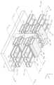
도 3a는 본 개시내용의 하나 이상의 실시예에 따른, 3D 메모리 셀 어레이, 이를테면 메모리 셀 어레이(200)의 일부분을 형성할 수 있는 반도체 구조(300)의 일부분의 등각도이다. 도 3b는, 도 3a에 도시된 라인(B-B')을 따른 반도체 구조(300)의 일부분의 단면도이다. 도 3c는, 도 3a에 도시된 라인(C-C')을 따른 반도체 구조(300)의 일부분의 단면도이다. 도 3d는, 도 3a에 도시된 라인(D-D')을 따른 반도체 구조(300)의 일부분의 단면도이다. 도 3e는, 도 3a에 도시된 라인(E-E')을 따른 반도체 구조(300)의 일부분의 단면도이다. 도시된 바와 같이, 2개의 메모리 레벨(L1 및 L2)이 기판(302) 상에 Z 방향으로 적층된다. 반도체 구조(300)는, Z 방향에서 제2 메모리 레벨(L2) 위에 적층되는 더 많은 메모리 레벨들(Ln (n = 3, 4, ...))(도시되지 않음)을 포함할 수 있다.FIG. 3A is an isometric view of a portion of a semiconductor structure (300) that may form a portion of a 3D memory cell array, such as a memory cell array (200), according to one or more embodiments of the present disclosure. FIG. 3B is a cross-sectional view of a portion of the semiconductor structure (300) along line (B-B') illustrated in FIG. 3A. FIG. 3C is a cross-sectional view of a portion of the semiconductor structure (300) along line (C-C') illustrated in FIG. 3A. FIG. 3D is a cross-sectional view of a portion of the semiconductor structure (300) along line (D-D') illustrated in FIG. 3A. FIG. 3E is a cross-sectional view of a portion of the semiconductor structure (300) along line (E-E') illustrated in FIG. 3A. As illustrated, two memory levels (L1 and L2 ) are stacked in the Z direction on a substrate (302). The semiconductor structure (300) may include more memory levels (Ln (n = 3, 4, ...)) (not shown) stacked on the second memory level (L2 ) in the Z direction.
반도체 구조(300)는, 좌측 전계 효과 트랜지스터(FET) 모듈(TRL), 트렌치(304)에 의해 X 방향에서 좌측 FET 모듈(TRL)로부터 분리되는 우측 FET 모듈(TRR)을 포함한다. 반도체 구조(300)는, X 방향에서 좌측 FET 모듈(TRL)에 인접한 좌측 커패시터 모듈(CL), 및 X 방향에서 우측 FET 모듈(TRR)에 인접한 우측 커패시터 모듈(CR)을 더 포함한다. 좌측 FET 모듈(TRL) 및 좌측 커패시터 모듈(CL)은 Y 방향에서 다수의 섹션들(SLm (m = 1, 2, 3, ...))로 분할된다(도 3a에서는 SL1, SL2, 및 SL3이 도시됨). 우측 FET 모듈(TRR) 및 우측 커패시터 모듈(CR)은 Y 방향에서 다수의 섹션들(SRm (m = 1, 2, 3, ...))로 분할된다(도 3a, 도 3c, 및 도 3d에서는 SR1, SR2, 및 SR3이 도시됨). 액세스 FET 트랜지스터(Q) 및 저장 커패시터(C)를 각각 형성하는, 각각의 섹션(SLm (m = 1, 2, 3))에서 각각의 메모리 레벨(Ln (n = 1, 2, ...))에 있는 좌측 FET 모듈(TRL) 및 좌측 커패시터 모듈(CL)은, 함께 메모리 셀(M)을 형성한다. 유사하게, 액세스 FET 트랜지스터(Q) 및 저장 커패시터(C)를 각각 형성하는, 각각의 섹션(SRm (m = 1, 2, 3))에서 각각의 메모리 레벨(Ln (n = 1, 2, ...))에 있는 우측 FET 모듈(TRR) 및 우측 커패시터 모듈(CR)은, 함께 메모리 셀(M)을 형성한다. 3개의 섹션(SLm (m = 1, 2, 3), 및 SRm (m = 1, 2, 3))만이 도시되지만, 더 많은 섹션들이 Y 방향을 따라 배치될 수 있다.A semiconductor structure (300) includes a left field effect transistor (FET) module (TRL ), a right FET module (TRR ) separated from the left FET module (TRL ) in the X-direction by a trench (304). The semiconductor structure (300) further includes a left capacitor module (CL ) adjacent to the left FET module (TRL ) in the X-direction, and a right capacitor module (CR ) adjacent to the right FET module (TRR ) in the X-direction. The left FET module (TRL ) and the left capacitor module (CL ) are divided into a plurality of sections (SLm (m = 1, 2, 3, ...)) in the Y-direction (SL1 , SL2 , and SL3 are illustrated in FIG. 3a ). The right FET module (TRR ) and the right capacitor module (CR ) are divided into a number of sections (SRm (m = 1, 2, 3, ...)) in the Y direction (SR1 , SR2 , and SR3 are illustrated in FIGS. 3a, 3c, and 3d). The left FET module (TR L ) and the left capacitor module (C L ) in each memory level (Ln (n = 1, 2, ...)) in each section (SLm (m = 1, 2, 3)), which respectively form an access FET transistor (Q ) and a storage capacitor (C ), together form a memory cell (M). Similarly, the right FET module (TR R ) and the right capacitor module (C R ) in each memory level (Ln (n = 1, 2, ...)) in each section (SRm (m = 1, 2, 3)), which form an access FET transistor (Q ) and a storage capacitor (C ), respectively, together form a memory cell (M). Only three sections (SLm (m = 1, 2, 3), and SRm (m = 1, 2, 3)) are shown, but more sections may be arranged along the Y direction.
본원에서 사용되는 바와 같은 "기판"이라는 용어는, 후속 처리 동작들을 위한 기초의 역할을 하고 세정될 표면을 포함하는 물질 층을 지칭한다. 기판(302)은, 필요에 따라, 규소 기재 물질 또는 임의의 적합한 절연 물질들 또는 전도성 물질들일 수 있다. 기판(302)은, 결정질 규소(예컨대, Si<100> 또는 Si<111>), 산화규소, 응력가해진 규소(strained silicon), 규소 게르마늄, 도핑되거나 도핑되지 않은 다결정질 규소, 도핑되거나 도핑되지 않은 규소 웨이퍼들들 및 패터닝되거나 패터닝되지 않은 웨이퍼들, 절연체 상 규소(silicon on insulator)(SOI), 탄소 도핑된 산화규소들, 질화규소, 도핑된 규소, 게르마늄, 비화갈륨, 유리, 또는 사파이어와 같은 물질을 포함할 수 있다.The term "substrate" as used herein refers to a material layer that serves as a foundation for subsequent processing operations and includes a surface to be cleaned. The substrate (302) may be a silicon-based material or any suitable insulating or conductive materials, as desired. The substrate (302) may include materials such as crystalline silicon (e.g., Si<100> or Si<111>), silicon oxide, strained silicon, silicon germanium, doped or undoped polycrystalline silicon, doped or undoped silicon wafers and patterned or unpatterned wafers, silicon on insulator (SOI), carbon doped silicon oxides, silicon nitride, doped silicon, germanium, gallium arsenide, glass, or sapphire.
메모리 레벨(Ln (n = 1, 2, ...))에 있는 FET 모듈들(TRL 및 TRR)은 각각 반도체 층(306) 및 워드 라인 금속 층(308a)을 포함한다. 일부 실시예들에서, 메모리 레벨(Ln (n = 1, 2, ...))에 있는 FET 모듈들(TRL 및 TRR)은 각각 워드 라인 금속 층(308b)을 더 포함한다. 반도체 층(306)의 단면들(306S)은 각각 대응하는 액세스 트랜지스터(Q)의 소스/드레인으로서의 역할을 한다. 메모리 레벨(Ln (n = 1, 2, ...))에 있는 워드 라인 금속 층(308a) 및 워드 라인 금속 층(308b)은 Y 방향으로 연장되며, 메모리 레벨(Ln) 내에서 서로 전기적으로 연결될 수 있다(연결 지점은 도시되지 않음). 반도체 층(306)은, 이중 게이트 구성에서, Z 방향에서 위 및 아래에 게이트 산화물들(310)을 갖는다. 워드 라인 금속 층들(308a 및 308b) 각각은, 워드 라인 금속 층들(308a, 308b) 주위에 있고 스페이서(312)에 매립되는 게이트 산화물들(310)을 갖는다. 메모리 레벨(Ln (n = 1, 2, ...))에 있는 FET 모듈들(TRL 및 TRR)은, 스페이서(312)에 의해, 인접한 메모리 레벨(Ln+1)에 있는 FET 모듈들(TRL 및 TRR)로부터 분리된다. 스페이서(312)는 또한, 메모리 레벨(Ln (n = 1, 2, ...)) 내에서 인접한 섹션들(예컨대, 도 3c에 도시된 바와 같은 SR1, SR2, 및 SR3) 간에 반도체 층(306)을 분리하도록 배치된다. 메모리 레벨(L1)에 있는 FET 모듈들(TRL 및 TRR)은 스페이서(312)에 의해 기판(302)으로부터 분리될 수 있다. 반도체 층들(306)은 각각, 약 20 nm 내지 약 60 nm, 예컨대 약 40 nm의 Y 방향에서의 폭, 및 약 10 nm 내지 약 30 nm, 예컨대 약 20 nm의 Z 방향에서의 두께를 가질 수 있다. Y 방향에서의 인접한 반도체 층들(306) 사이의 수평 간격은 약 140 nm 내지 약 180 nm, 예컨대 약 160 nm일 수 있고, Z 방향에서의 인접한 반도체 층들(306) 사이의 수직 간격은 약 50 nm 내지 약 100 nm, 예컨대 약 80 nm일 수 있다. 비트 라인들(BL)은, 약 40 nm 내지 약 120 nm, 예컨대 약 80 nm의 Y 방향에서의 폭, 및 약 40 nm 내지 약 120 nm, 예컨대 약 80 nm의 X 방향에서의 두께를 가질 수 있다. 일부 메모리 어레이 설계들에서, BL은 트렌치(304)에 걸쳐 좌측 FET 모듈(TRL) 및 우측 FET 모듈(TRR)에 공통이고, 그에 따라, X 방향에서의 비트 라인(BL)의 폭은 트렌치(304)의 폭이다. 이러한 설계에서, 좌측 FET 모듈(TRL) 상의 그리고 우측 FET 모듈(TRR) 상의 워드 라인들(WL)은 2개의 논리적 워드 라인 어드레스들을 어드레싱하고 별개로 제어될 수 있다. 일부 다른 메모리 어레이 설계들에서, 2개의 별개의 비트 라인(BL), 즉, 좌측 FET 모듈(TRL) 상의 하나의 비트 라인 및 우측 FET 모듈(TRR) 상의 다른 하나의 비트 라인이 형성된다. 이러한 비트 라인들(BL)은 서로 격리되며 상이한 전역 비트 라인에 별개로 연결될 수 있다. 단일 워드 라인 연결이 좌측 워드 라인(WL) 및 우측 워드 라인(WL)에 대해 사용될 수 있게 하여, 깊은 워드 라인 "계단구조" 접촉부들에 대해 요구되는 수와 그에 따른 영역이 크게 감소된다.The FET modules (TRL and TRR ) in the memory level (Ln (n = 1, 2, ...)) each include a semiconductor layer (306) and a word line metal layer (308a). In some embodiments, the FET modules (TRL and TRR ) in the memory level (Ln (n = 1, 2, ...)) each further include a word line metal layer (308b). The cross-sections (306S) of the semiconductor layer (306) each serve as a source/drain of a corresponding access transistor (Q). The word line metal layer (308a) and the word line metal layer (308b) in the memory level (Ln (n = 1, 2, ...)) extend in the Y direction and may be electrically connected to each other within the memory level (Ln ) (connection points not shown). The semiconductor layer (306) has gate oxides (310) above and below in the Z direction in a dual gate configuration. Each of the word line metal layers (308a and 308b) has gate oxides (310) surrounding the word line metal layers (308a, 308b) and embedded in a spacer (312). The FET modules (TRL and TRR ) in the memory level (Ln (n = 1, 2, ...)) are separated from the FET modules (TRL and TRR ) in the adjacent memory level (Ln+1 ) by the spacer (312). The spacer (312) is also positioned to separate the semiconductor layer (306) between adjacent sections (e.g., SR1 , SR2 , and SR3 as illustrated in FIG. 3c ) within the memory level (Ln ( n = 1, 2, ...). The FET modules (TRL and TRR ) in the memory level (L1 ) can be separated from the substrate (302) by the spacer (312). The semiconductor layers (306) can each have a width in the Y direction of about 20 nm to about 60 nm, for example, about 40 nm, and a thickness in the Z direction of about 10 nm to about 30 nm, for example, about 20 nm. The horizontal spacing between adjacent semiconductor layers (306) in the Y direction can be about 140 nm to about 180 nm, for example, about 160 nm, and the vertical spacing between adjacent semiconductor layers (306) in the Z direction can be about 50 nm to about 100 nm, for example, about 80 nm. The bit lines (BL) can have a width in the Y direction of about 40 nm to about 120 nm, for example, about 80 nm, and a thickness in the X direction of about 40 nm to about 120 nm, for example, about 80 nm. In some memory array designs, the BL is common to the left FET module (TRL ) and the right FET module (TRR ) across the trench (304), such that the width of the bit line (BL) in the X direction is the width of the trench (304). In such a design, the word lines (WL) on the left FET module (TRL ) and the right FET module (TRR ) can be addressed with two logical word line addresses and controlled separately. In some other memory array designs, two separate bit lines (BL) are formed, one bit line on the left FET module (TRL ) and the other bit line on the right FET module (TRR ). These bit lines (BL) are isolated from each other and can be separately connected to different global bit lines. This allows a single word line connection to be used for both the left word line (WL) and the right word line (WL), thus greatly reducing the number and therefore area required for deep word line "staircase" contacts.
반도체 층(306)은 규소(Si) 또는 규소 게르마늄(SiGe)으로 형성될 수 있다. 워드 라인 금속 층들(308a, 308b)은 구리(Cu), 코발트(Co), 텅스텐(W), 티타늄(Ti), 몰리브데넘(Mo), 니켈(Ni), 루테늄(Ru), 은(Ag), 금(Au), 이리듐(Ir), 탄탈럼(Ta), 또는 백금(Pt), 또는 이들의 전도성 산화물들 또는 질화물들, 또는 이들의 임의의 조합물로 형성될 수 있다. 게이트 산화물들(310)은 산화규소(SiO2), 산질화규소(SiON), 고-유전상수(high-k) 유전체 물질, 이를테면, 산화하프늄(HfO2), 산화지르코늄(ZrO2), 산화바나듐(VO2), 산화티타늄(TiO2), 산화알루미늄(Al2O3), 하프늄 규소 산화물(HfSiO), 지르코늄 규소 산화물(ZrSiO), 산화니오븀(Nb2O5), 오산화탄탈럼(Ta2O5), 또는 이들의 임의의 조합물로 형성될 수 있다. 스페이서(312)는 유전체 물질, 이를테면, 이산화규소(SiO2), 질화규소(Si3N4), 산질화규소(SiON), 산탄화규소(SiOCN), 붕소-도핑된 산탄질화규소(SiOCBN), 또는 이들의 임의의 조합물로 형성될 수 있다.The semiconductor layer (306) may be formed of silicon (Si) or silicon germanium (SiGe). The word line metal layers (308a, 308b) may be formed of copper (Cu), cobalt (Co), tungsten (W), titanium (Ti), molybdenum (Mo), nickel (Ni), ruthenium (Ru), silver (Ag), gold (Au), iridium (Ir), tantalum (Ta), or platinum (Pt), or conductive oxides or nitrides thereof, or any combination thereof. The gate oxides (310) can be formed of silicon oxide (SiO2 ), silicon oxynitride (SiON), a high-k dielectric material such as hafnium oxide (HfO2 ), zirconium oxide (ZrO2 ), vanadium oxide (VO2 ), titanium oxide (TiO2 ), aluminum oxide (Al2 O3 ), hafnium silicon oxide (HfSiO), zirconium silicon oxide (ZrSiO), niobium oxide (Nb2 O5 ), tantalum pentoxide (Ta2 O5 ), or any combination thereof. The spacer (312) may be formed of a dielectric material, such as silicon dioxide (SiO2 ), silicon nitride (Si3 N4 ), silicon oxynitride (SiON), silicon oxycarbonate (SiOCN), boron-doped silicon oxycarbonate (SiOCBN), or any combination thereof.
메모리 레벨(Ln (n = 1, 2, ...))에 있는 좌측 커패시터 모듈(CL) 및 우측 커패시터 모듈(CR)은 각각, 메모리 레벨(Ln) 내에서 반도체 층(306)에 전기적으로 연결되는 제1 플레이트 금속 층(314), 접지(도시되지 않음)되는 제2 플레이트 금속 층(316), 및 제1 플레이트 금속 층(314)과 제2 플레이트 금속 층(316) 사이의 유전체 층(318)을 포함한다. 제1 플레이트 금속 층들(314)은 유전체 층(320)에 의해 둘러싸인다. 유전체 층(320)은 또한, 인접한 섹션들(예컨대, 도 3d에 도시된 바와 같은 SR1, SR2, 및 SR3) 간에 제1 플레이트 금속 층들(314), 제2 플레이트 금속 층들(316), 및 유전체 층들(320)을 분리하도록 배치된다. 제1 플레이트 금속 층(314)과 반도체 층(306) 사이에, 확산 장벽 층(도시되지 않음)이 개재될 수 있다. 제1 플레이트 금속 층(314) 및 제2 플레이트 금속 층(316)은 커패시터(C)의 2개의 플레이트의 역할을 할 수 있다. 제1 플레이트 금속 층(314) 및 제2 플레이트 금속 층들(316)은 코발트(Co), 텅스텐(W), 알루미늄(Al), 루테늄(Ru), 이리듐(Ir), 몰리브데넘(Mo), 백금(Pt), 탄탈럼(Ta), 티타늄(Ti), 로듐(Rh), 또는 전도성 금속 질화물들, 또는 이들의 임의의 조합물로 형성될 수 있다. 유전체 층(318)은, 이를테면, 산화하프늄(HfO2), 산화지르코늄(ZrO2), 산화바나듐(VO2), 산화티타늄(TiO2), 산화주석(SnO2), 산화알루미늄(Al2O3), 산화아연(ZnO), 하프늄 규소 산화물(HfSiO), 지르코늄 규소 산화물(ZrSiO), 산화니오븀(Nb2O5), 오산화탄탈럼(Ta2O5), 또는 이들의 임의의 조합물과 같은 고-유전상수 유전체 물질로 형성될 수 있다.The left capacitor module (CL ) and the right capacitor module (CR ) in the memory level (Ln (n = 1, 2, ...)) each include a first plate metal layer (314) electrically connected to the semiconductor layer (306) within the memory level (Ln ), a second plate metal layer (316) that is grounded (not shown), and a dielectric layer (318) between the first plate metal layer (314) and the second plate metal layer (316). The first plate metal layers (314) are surrounded by a dielectric layer (320). The dielectric layer (320) is also arranged to separate the first plate metal layers (314), the second plate metal layers (316), and the dielectric layers (320) between adjacent sections (e.g., SR1 , SR2 , and SR3 as shown in FIG. 3d ). A diffusion barrier layer (not shown) may be interposed between the first plate metal layer (314) and the semiconductor layer (306). The first plate metal layer (314) and the second plate metal layer (316) may function as two plates of the capacitor (C). The first plate metal layer (314) and the second plate metal layers (316) may be formed of cobalt (Co), tungsten (W), aluminum (Al), ruthenium (Ru), iridium (Ir), molybdenum (Mo), platinum (Pt), tantalum (Ta), titanium (Ti), rhodium (Rh), or conductive metal nitrides, or any combination thereof. The dielectric layer (318) can be formed of a high-k dielectric material, such as, for example, hafnium oxide (HfO2 ), zirconium oxide (ZrO2 ), vanadium oxide (VO2 ), titanium oxide (TiO2 ), tin oxide (SnO2 ), aluminum oxide (Al2 O3 ), zinc oxide (ZnO), hafnium silicon oxide (HfSiO), zirconium silicon oxide (ZrSiO), niobium oxide (Nb2 O5 ), tantalum pentoxide (Ta2 O5 ), or any combination thereof.
반도체 구조(300)는, 좌측 FET 모듈(TRL) 및 우측 FET 모듈(TRR)의 인접한 섹션들(SLm (m = 1, 2, 3, ...)) 및 SRm (m = 1, 2, 3, ...)) 사이에서(예컨대, 도 3a 및 도 3e에 도시된 바와 같이, 섹션들(SL1 및 SR1) 사이에서, 섹션들(SL2 및 SR2) 사이에서, 그리고 섹션들(SL3 및 SR3) 사이에서) 트렌치(304) 내에서 Z 방향으로 연장되는 비트 라인들(BL)을 더 포함한다. 섹션들(SLm 및 SRm (m = 1, 2, 3, ...)) 사이의 비트 라인(BL)은 반도체 층들(306)의 단면들(306S) 상의 인터페이스들(322)과 직접 접촉하고, 모든 메모리 레벨들(Ln (n = 1, 2, ...))에서 섹션(SLm)에 있는 좌측 FET 모듈(TRL)의 인터페이스들(322)을 통해 반도체 층들(306)에 전기적으로 연결된다. 섹션들(SLm 및 SRm (m = 1, 2, 3, ...)) 사이의 비트 라인(BL)은 추가로, 규소 층들(306)의 단면들(306S) 상의 인터페이스들(322)과 직접 접촉하고, 모든 메모리 레벨들(Ln (n = 1, 2, ...))에서 섹션(SRm)에 있는 우측 FET 모듈(TRR)의 인터페이스들(322)을 통해 반도체 층들(306)에 전기적으로 연결된다.The semiconductor structure (300) further includes bit lines (BL) extending in the Z direction within trenches (304) between adjacent sections (SLm (m = 1, 2, 3, ...)) and SRm (m = 1, 2, 3, ...)) of the left FET module (TR L ) and the right FET module (TR R ) (e.g., between sections (SL1 and SR1 ), between sections (SL2 and SR2 ), and between sections (SL3 and SR3 ) as shown in FIGS. 3A and 3E ). The bit lines (BL) between the sections (SLm and SRm (m = 1, 2, 3, ...)) are in direct contact with the interfaces (322) on the cross-sections (306S) of the semiconductor layers (306) and are electrically connected to the semiconductor layers (306) through the interfaces (322) of the left FET module (TRL ) in the section (SLm ) in all memory levels (Ln (n = 1, 2, ...)). The bit lines (BL) between the sections (SLm and SRm (m = 1, 2, 3, ...)) are additionally in direct contact with the interfaces (322) on the cross-sections (306S) of the silicon layers (306) and are electrically connected to the semiconductor layers (306) through the interfaces (322) of the right FET module (TRR ) in the section (SRm ) in all memory levels (Ln (n = 1, 2, ...)).
종래에, 비트 라인들(BL)은, 도핑된 폴리실리콘 또는 다른 전도성 물질로 트렌치(304)를 충전하고 완성된 비트 라인(BL)으로서 전도성 물질을 남기기 위해 비트 라인들(BL) 사이에 수직 격리 갭들을 식각하여 제거(etch away)하는 것에 의해, 또는 트렌치(304) 내의 유전체 물질의 증착 및 그들 아래의 소스-드레인 구역들 각각에 연결될 수직 접촉 홀들을 식각하는 것에 의해 형성된다. 두 경우 모두에서, 좌측 FET 모듈(TRL) 및 우측 FET 모듈(TRR)에 대한 공통 비트 라인(BL)이 형성된다.Conventionally, the bit lines (BL) are formed by either filling the trenches (304) with doped polysilicon or other conductive material and etching away vertical isolation gaps between the bit lines (BL) to leave the conductive material as the completed bit lines (BL), or by depositing dielectric material within the trenches (304) and etching vertical contact holes to connect to each of the source-drain regions beneath them. In both cases, a common bit line (BL) is formed for the left FET module (TRL ) and the right FET module (TRR ).
본원에서 설명된 실시예들에서, 비트 라인들(BL)은, 좌측 FET 모듈(TRL) 및 우측 FET 모듈(TRR) 상의 2개의 별개의 비트 라인(BL)을 또한 허용할 수 있는 선택적 증착들을 사용하여 형성된다. 먼저, 반도체 층(306)의 노출된 단면들(306S)에 대해 적합한 도핑 방법을 사용하여, 도핑된 소스/드레인 구역들이 형성된다. 이러한 도핑된 소스/드레인 구역들은 수직으로 비트 라인(BL)을 연결하도록 브릿징될 수 있거나 그렇지 않을 수 있다. 후속하여, 금속의 다른 선택적 증착이 수행되어, 금속 실리사이드 인터페이스들(322)이 형성되고, 이어서, 동일하거나 심지어 상이한 금속의 증착이 후속되어, 금속 상호연결 층(도 5c에서 502로서 참조됨)이 형성된다. 금속 실리사이드는 몰리브데넘 실리사이드(MoxSiy), 티타늄 실리사이드(TixSiy), 코발트 실리사이드(CoxSiy), 니켈(NixSiy), 탄탈럼 실리사이드(TaxSiy), 또는 이들의 임의의 조합물일 수 있다. 인터페이스들(322)은 반도체 층들(306)과 비트 라인들(BL) 사이에 옴 접촉을 제공한다. 비트 라인들(BL)은 금속, 이를테면, 몰리브데넘(Mo), 티타늄(Ti), 코발트(Co), 니켈(Ni), 탄탈럼(Ta), 또는 이들의 임의의 조합물로 형성될 수 있다. 선택적으로 증착된 물질들은, 그 물질들이 브릿징되고 연속적인 수직 연결을 형성하여 비트 라인(BL)을 형성하는 한, 규소 층, 실리사이드 층, 또는 금속 층, 또는 이들의 임의의 조합물일 수 있다. 트렌치(304) 및 비트 라인들(BL)에는 최종적으로, 비트 라인들(BL)을 격리시키기 위한 유전체 층(324)이 주어지며, 이는 또한, 트렌치(304)를 부분적으로 또는 완전히 충전할 수 있다. 트렌치(304)는 비트 라인들(BL)의 기생 커패시턴스를 감소시키기 위해 표면 아래에 공기-갭들이 매립된 채로 남겨질 수 있지만, 개별 수직 비트 라인들(BL)에 대한 최상부 상호연결 라인들의 처리를 허용하기 위해 최상부 표면에서 밀봉된다. 유전체 층(324)은 유전체 물질, 이를테면, 이산화규소(SiO2), 질화규소(Si3N4), 산질화규소(SiON), 질화붕소(BN), 산탄화규소(SiOCN), 붕소-도핑된 산탄질화규소(SiOCBN), 산화알루미늄(Al2O3), 또는 산화하프늄(HfO2), 또는 이들의 임의의 조합물로 형성된다.In the embodiments described herein, the bit lines (BL) are formed using selective depositions that may also allow for two separate bit lines (BL) on the left FET module (TRL ) and the right FET module (TRR ). First, doped source/drain regions are formed using a suitable doping method on the exposed cross-sections (306S) of the semiconductor layer (306). These doped source/drain regions may or may not be bridged to vertically connect the bit lines (BL). Subsequently, another selective deposition of metal is performed to form metal silicide interfaces (322), followed by deposition of the same or even a different metal to form a metal interconnect layer (referenced as 502 in FIG. 5c ). The metal silicide can be molybdenum silicide (Mox Siy ), titanium silicide (Tix Siy ), cobalt silicide (Cox Siy ), nickel (Nix Siy ), tantalum silicide (Tax Siy ), or any combination thereof. The interfaces (322) provide ohmic contact between the semiconductor layers (306) and the bit lines (BL). The bit lines (BL) can be formed of a metal, such as molybdenum (Mo), titanium (Ti), cobalt (Co), nickel (Ni), tantalum (Ta), or any combination thereof. The optionally deposited materials can be a silicon layer, a silicide layer, or a metal layer, or any combination thereof, as long as the materials bridge and form a continuous vertical connection to form the bit lines (BL). The trench (304) and the bit lines (BL) are finally provided with a dielectric layer (324) to isolate the bit lines (BL), which may also partially or completely fill the trench (304). The trench (304) may be left with air gaps buried beneath the surface to reduce parasitic capacitance of the bit lines (BL), but is sealed at the top surface to allow processing of the top interconnect lines for the individual vertical bit lines (BL). The dielectric layer (324) is formed of a dielectric material, such as silicon dioxide (SiO2 ), silicon nitride (Si3 N4 ), silicon oxynitride (SiON), boron nitride (BN), silicon oxycarbide (SiOCN), boron-doped silicon oxycarbide (SiOCBN), aluminum oxide (Al2 O3 ), or hafnium oxide (HfO2 ), or any combination thereof.
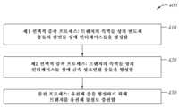
도 4는 본 개시내용의 하나 이상의 구현에 따른, 반도체 구조(300)에서 FET 모듈들(TRL 및 TRR) 사이에 비트 라인(BL)을 형성하는 방법(400)의 프로세스 흐름도를 묘사한다. 도 5a 및 도 5c는 도 3a에 도시된 라인(B-B')을 따른 반도체 구조(300)의 일부분의 단면도들이고, 도 5b, 도 5d, 및 도 5e는 도 3a에 도시된 라인(E-E')을 따른 반도체 구조(300)의 일부분의 단면도들이며, 이들은 방법(400)의 다양한 상태들에 대응한다. 도 5a, 도 5b, 도 5c, 도 5d, 및 도 5e는 반도체 구조(300)의 부분적인 개략도들만을 예시하고, 반도체 구조(300)는 도면들에 예시된 바와 같은 양상들을 갖는 임의의 수의 트랜지스터 섹션들 및 부가적인 물질들을 포함할 수 있다는 것이 이해되어야 한다. 또한, 도 4에 예시된 방법이 순차적으로 설명되지만, 생략 및/또는 부가되고/거나 다른 바람직한 순서로 재배열된 하나 이상의 동작을 포함하는 다른 프로세스 시퀀스들이 본원에서 제공되는 본 개시내용의 실시예들의 범위 내에 속한다는 것이 유의되어야 한다.FIG. 4 depicts a process flow diagram of a method (400) of forming a bit line (BL) between FET modules (TRL and TRR ) in a semiconductor structure (300) according to one or more implementations of the present disclosure. FIGS. 5A and 5C are cross-sectional views of a portion of the semiconductor structure (300) along line (B-B') illustrated in FIG. 3A , and FIGS. 5B , 5D , and 5E are cross-sectional views of a portion of the semiconductor structure (300) along line (E-E') illustrated in FIG. 3A , corresponding to various states of the method (400). It should be understood that FIGS. 5A , 5B, 5C, 5D, and 5E illustrate only partial schematic views of the semiconductor structure (300) and that the semiconductor structure (300) may include any number of transistor sections and additional materials having aspects such as those illustrated in the drawings. Additionally, it should be noted that although the method illustrated in FIG. 4 is described sequentially, other process sequences that include one or more operations omitted and/or added and/or rearranged in a different preferred order are within the scope of the embodiments of the present disclosure provided herein.
반도체 층들(306), 워드 라인 금속 층들(308a), 워드 라인 금속 층들(308b), 게이트 산화물들(310), 스페이서(312), 제1 플레이트 금속 층들(314), 제2 플레이트 금속 층들(316), 유전체 층들(318), 유전체 층들(320), 및 유전체 층들(324)을 포함하는 반도체 구조(300)의 FET 모듈들(TRL 및 TRR)은, 방법(400)에 의해 비트 라인(BL)을 형성하기 전에, 임의의 적합한 증착 기법, 이를테면, 화학 기상 증착(CVD), 원자 층 증착(ALD), 또는 물리 기상 증착(PVD), 및 패터닝 기법, 이를테면, 리소그래피 및 식각 프로세스를 사용하여 형성될 수 있다. 반도체 층들(306)은 각각, 약 20 nm 내지 약 60 nm, 예컨대 약 40 nm의 Y 방향에서의 폭, 및 약 10 nm 내지 약 30 nm, 예컨대 약 20 nm의 Z 방향에서의 두께를 가질 수 있다. Y 방향에서의 인접한 반도체 층들(306) 사이의 수평 간격은 약 140 nm 내지 약 180 nm, 예컨대 약 160 nm일 수 있고, Z 방향에서의 인접한 반도체 층들(306) 사이의 수직 간격은 약 50 nm 내지 약 100 nm, 예컨대 약 80 nm일 수 있다. 비트 라인들(BL)은, 약 40 nm 내지 약 120 nm, 예컨대 약 80 nm의 Y 방향에서의 폭, 및 약 40 nm 내지 약 120 nm, 예컨대 약 80 nm의 X 방향에서의 두께를 가질 수 있다.The FET modules (TR L and TR R ) of the semiconductor structure (300), including semiconductor layers (306), word line metal layers (308a), word line metal layers (308b), gate oxides (310), spacers (312 ), first plate metal layers (314), second plate metal layers (316), dielectric layers (318), dielectric layers (320), and dielectric layers (324), can be formed using any suitable deposition technique, such as chemical vapor deposition (CVD), atomic layer deposition (ALD), or physical vapor deposition (PVD ), and patterning techniques, such as lithography and etching processes, prior to forming the bit line (BL) by the method (400). The semiconductor layers (306) can each have a width in the Y direction of about 20 nm to about 60 nm, for example, about 40 nm, and a thickness in the Z direction of about 10 nm to about 30 nm, for example, about 20 nm. A horizontal spacing between adjacent semiconductor layers (306) in the Y direction can be about 140 nm to about 180 nm, for example, about 160 nm, and a vertical spacing between adjacent semiconductor layers (306) in the Z direction can be about 50 nm to about 100 nm, for example, about 80 nm. The bit lines (BL) can have a width in the Y direction of about 40 nm to about 120 nm, for example, about 80 nm, and a thickness in the X direction of about 40 nm to about 120 nm, for example, about 80 nm.
방법(400)은 블록(410)으로 시작되며, 여기서, 도 5a 및 5b에 도시된 바와 같이, (반도체 층들(306)의 단면들(306S), 게이트 산화물들(310)의 단면들(310S), 및 스페이서(312)의 단면들(312S)을 포함하는) 트렌치(304)의 측벽들 상의 반도체 층들(306)의 노출된 단면들(306S) 상에 자기-정렬된 인터페이스들(322)을 형성하기 위한 제1 선택적 증착 프로세스가 수행된다. 제1 선택적 증착은, 반도체 층(306)의 단면(306S)에 도핑된 소스/드레인 구역을 형성하기 위한 적합한 도핑 방법으로 시작된다. 제1 선택적 증착은, 반도체 층(306)의 노출된 단면(306S)에 인터페이스(322)를 형성하기 위한, 금속 실리사이드, 이를테면, 몰리브데넘 실리사이드(MoxSiy), 티타늄 실리사이드(TixSiy), 코발트 실리사이드(CoxSiy), 니켈(NixSiy), 탄탈럼 실리사이드(TaxSiy), 또는 이들의 임의의 조합물의 선택적 증착으로 계속된다. 인터페이스들(322)은, 반도체 층들(306)과 형성될 비트 라인(BL) 사이에 옴 접촉들을 제공한다.The method (400) begins with block (410), where a first selective deposition process is performed to form self-aligned interfaces (322) on exposed cross-sections (306S) of the semiconductor layers (306) on sidewalls of the trench (304) (including cross-sections (306S) of the semiconductor layers (306), cross-sections (310S) of the gate oxides (310), and cross-sections (312S) of the spacer (312), as illustrated in FIGS. 5A and 5B . The first selective deposition begins with a suitable doping method to form doped source/drain regions in the cross-sections (306S) of the semiconductor layers (306). The first selective deposition continues with a selective deposition of a metal silicide, such as molybdenum silicide (Mox Siy ), titanium silicide (Tix Siy ), cobalt silicide (Cox Siy ), nickel (Ni x Si y ), tantalum silicide (TaxSiy ), or any combination thereof, to form interfaces( 322) on the exposed cross-sections (306S) of the semiconductor layers (306). The interfaces (322) provide ohmic contacts between the semiconductor layers (306) and the bit lines (BL) to be formed.
일부 실시예들에서, 금속 소스는 몰리브데넘(Mo), 티타늄(Ti), 코발트(Co), 니켈(Ni), 탄탈럼(Ta), 또는 이들의 임의의 조합물을 포함할 수 있다. 식각 가스는 식각제 가스 및 캐리어 가스를 포함하며, 여기서, 식각제 가스는 증착 가스 그 자체의 부산물일 수 있다. 식각제 가스는 염소 함유 가스, 이를테면, 염화수소(HCl), 염소(Cl2), 사염화탄소(CCl4), 클로로포름(CHCl3), 디클로로메탄(CH2Cl2), 또는 클로로메탄(CH3Cl)을 포함할 수 있다. 캐리어 가스는 질소(N2), 아르곤(Ar), 헬륨(He), 또는 수소(H2)를 포함할 수 있다.In some embodiments, the metal source can include molybdenum (Mo), titanium (Ti), cobalt (Co), nickel (Ni), tantalum (Ta), or any combination thereof. The etching gas includes an etchant gas and a carrier gas, wherein the etchant gas can be a byproduct of the deposition gas itself. The etchant gas can include a chlorine-containing gas, such as hydrogen chloride (HCl), chlorine (Cl2 ), carbon tetrachloride (CCl4 ), chloroform (CHCl3 ), dichloromethane (CH2 Cl2 ), or chloromethane (CH3 Cl). The carrier gas can include nitrogen (N2 ), argon (Ar), helium (He), or hydrogen (H2 ).
증착 프로세스는 임의의 적절한 증착 프로세스, 이를테면, 에피택셜 증착, 원자 층 증착(ALD), 화학 기상 증착(CVD), 스핀-온, 물리 기상 증착(PVD) 등을 포함할 수 있다. 블록(410)에서의 증착 프로세스 및 식각 프로세스는 각각, 처리 챔버, 이를테면, 도 1에 도시된 처리 챔버(120, 122, 124, 126, 128, 또는 130)에서, 약 300 ℃ 내지 약 800 ℃의 온도로 그리고 1 Torr 내지 50 Torr의 압력으로 수행될 수 있다.The deposition process may include any suitable deposition process, such as epitaxial deposition, atomic layer deposition (ALD), chemical vapor deposition (CVD), spin-on, physical vapor deposition (PVD), etc. The deposition process and the etch process at block (410) may each be performed in a processing chamber, such as the processing chamber (120, 122, 124, 126, 128, or 130) illustrated in FIG. 1, at a temperature of about 300 °C to about 800 °C and a pressure of about 1 Torr to 50 Torr.
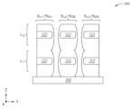
블록(420)에서, 도 5c 및 5d에 도시된 바와 같이, (인터페이스들(322), 게이트 산화물들(310)의 단면들(310S), 및 스페이서(312)의 단면들(312S)을 포함하는) 트렌치(304)의 측벽들상의 인터페이스들(322)의 노출된 표면들 상에 자기-정렬되는 금속 상호연결 층들(502)을 형성하기 위해 제2 선택적 증착 프로세스가 수행된다. 제2 선택적 증착 프로세스는 블록(410)에서의 제1 선택적 증착 프로세스의 연속이며, 이에 따라, 인터페이스들(322) 상의 물질의 순 증착(net deposition), 및 (게이트 산화물들(310)의 단면들(310S) 및 스페이서(312)의 단면들(312S)을 포함하는) 트렌치(304)의 측벽들의 주변 표면들 상의 물질의 영 증착(zero deposition) 또는 순 식각(net etching)이 존재한다. 증착 프로세스에서, 트렌치(304)의 노출된 표면들은 금속 소스를 함유하는 증착 가스에 노출된다. 금속 소스는, 블록(410)에서 사용된 금속 소스와 동일하거나 블록(410)에서 사용된 금속 소스와 상이할 수 있다. 인터페이스들(322)은 금속 소스와 반응하여 금속 상호연결 층들(502)을 형성할 수 있다. 금속 상호연결 층들(502)은 인터페이스들(322) 각각으로부터 X 방향으로는 트렌치(304)의 중간을 향해 그리고 Y-Z 평면에서는 등방성으로 성장하고, 인접한 인터페이스들(322)로부터 성장하는 부분들과 병합된다. 도 3b 및 도 3e에 도시된 바와 같이, FET 모듈(TRL)에 인접한 병합된 금속 상호연결 층들(502)은 추가로, FET 모듈(TRR)에 인접한 병합된 금속 상호연결 층들(502)과 병합되고, 연속적인 비트 라인(BL)을 형성한다. 일부 다른 실시예들에서, FET 모듈(TRL)에 인접한 병합된 금속 상호연결 층들(502)은 단독으로 비트 라인(BL)을 형성하고, FET 모듈(TRR)에 인접한 병합된 금속 상호연결 층들(502)은 별개의 비트 라인(BL)을 형성한다.In block (420), a second optional deposition process is performed to form self-aligned metal interconnect layers (502) on exposed surfaces of the interfaces (322) on the sidewalls of the trenches (304) (including the interfaces (322), the cross-sections (310S) of the gate oxides (310), and the cross-sections (312S) of the spacer (312), as illustrated in FIGS. 5c and 5d . The second optional deposition process is a continuation of the first optional deposition process in block (410), such that there is a net deposition of material on the interfaces (322) and a zero deposition or net etching of material on the peripheral surfaces of the sidewalls of the trenches (304) (including the cross-sections (310S) of the gate oxides (310) and the cross-sections (312S) of the spacer (312). In the deposition process, the exposed surfaces of the trenches (304) are exposed to a deposition gas containing a metal source. The metal source may be the same as the metal source used in block (410) or different from the metal source used in block (410). The interfaces (322) may react with the metal source to form metal interconnect layers (502). The metal interconnect layers (502) grow isotropically in the X direction and in the YZ plane from each of the interfaces (322) toward the center of the trenches (304) and merge with portions growing from adjacent interfaces (322). As illustrated in FIGS. 3b and 3e, the merged metal interconnect layers (502) adjacent to the FET modules (TRL ) are further merged with the merged metal interconnect layers (502) adjacent to the FET modules (TRR ) to form a continuous bit line (BL). In some other embodiments, the merged metal interconnect layers (502) adjacent to the FET module (TRL ) form a bit line (BL) alone, and the merged metal interconnect layers (502) adjacent to the FET module (TRR ) form a separate bit line (BL).
일부 실시예들에서, 금속 소스는 몰리브데넘(Mo), 티타늄(Ti), 코발트(Co), 니켈(Ni), 탄탈럼(Ta), 또는 이들의 임의의 조합물을 포함할 수 있다.In some embodiments, the metal source may include molybdenum (Mo), titanium (Ti), cobalt (Co), nickel (Ni), tantalum (Ta), or any combination thereof.
블록(430)에서, 도 5e에 도시된 바와 같이, 유전체 층(324)을 형성하기 위해 트렌치(304)를 유전체 물질로 충전하도록 충전 프로세스가 수행된다.In block (430), a filling process is performed to fill the trench (304) with a dielectric material to form a dielectric layer (324), as illustrated in FIG. 5e.
유전체 층(324)은 유전체 물질, 이를테면, 이산화규소(SiO2), 질화규소(Si3N4), 산질화규소(SiON), 질화붕소(BN), 산탄화규소(SiOCN), 붕소-도핑된 산탄질화규소(SiOCBN), 산화알루미늄(Al2O3), 또는 산화하프늄(HfO2), 또는 이들의 임의의 조합물로 형성된다.The dielectric layer (324) is formed of a dielectric material, such as silicon dioxide (SiO2 ), silicon nitride (Si3 N4 ), silicon oxynitride (SiON), boron nitride (BN), silicon oxycarbide (SiOCN), boron-doped silicon oxycarbide (SiOCBN), aluminum oxide (Al2 O3 ), or hafnium oxide (HfO2 ), or any combination thereof.
블록(430)에서의 충전 프로세스는 처리 챔버, 이를테면 도 1에 도시된 처리 챔버(120, 122, 124, 126, 128, 또는 130)에서의 임의의 적절한 증착 프로세스, 이를테면 화학 기상 증착(CVD) 프로세스를 포함할 수 있다.The charging process in block (430) may include any suitable deposition process, such as a chemical vapor deposition (CVD) process, in a processing chamber, such as processing chamber (120, 122, 124, 126, 128, or 130) illustrated in FIG. 1.
본원에서 설명된 실시예들은, 메모리 셀을 형성하는 FET 디바이스와 수직 비트 라인들 사이의 인터페이스들을 갖는 3D DRAM 디바이스들에서 수직 비트 라인들을 형성하기 위한 시스템들 및 방법들을 제공한다. 수직 비트 라인들은, 수직 비트 라인들을 위한 슬롯들을 형성하기 위해 HAR 식각 프로세스를 필요로 함이 없이, 금속, 이를테면 몰리브데넘(Mo)의 자기-정렬 증착 프로세스에 의해 형성된다. 그에 따라, 비트 라인들로서 종래에 사용되었던 공극들을 포함할 수 있는 다결정질과 비교하여, 비트 라인들의 저항이 감소된다. 인터페이스들은, 선택적 자기-정렬 증착 프로세스에 의해 금속 실리사이드, 이를테면 몰리브데넘 실리사이드(MoSi2)로 형성되고, FET 디바이스와 수직 비트 라인들 사이의 옴 접촉을 제공하며, 이는 접촉 기생 저항을 감소시킨다.Embodiments described herein provide systems and methods for forming vertical bit lines in 3D DRAM devices having interfaces between a FET device forming a memory cell and vertical bit lines. The vertical bit lines are formed by a self-aligned deposition process of a metal, such as molybdenum (Mo), without requiring a HAR etch process to form slots for the vertical bit lines. As a result, the resistance of the bit lines is reduced compared to polycrystalline ones that may include voids conventionally used as bit lines. The interfaces are formed of a metal silicide, such as molybdenum silicide (MoSi2 ), by a selective self-aligned deposition process and provide an ohmic contact between the FET device and the vertical bit lines, which reduces contact parasitic resistance.
전술한 내용이 본 개시내용의 실시예들에 관한 것이지만, 본 개시내용의 다른 그리고 추가적인 실시예들이 본 개시내용의 기본적인 범위로부터 벗어나지 않으면서 고안될 수 있으며, 본 개시내용의 범위는 하기의 청구항들에 의해 결정된다.While the foregoing is directed to embodiments of the present disclosure, other and further embodiments of the present disclosure may be devised without departing from the basic scope thereof, and the scope of the present disclosure is determined by the claims that follow.
Claims (20)
Translated fromKorean제1 방향으로 적층되는 복수의 메모리 레벨들 ― 상기 복수의 메모리 레벨들 각각은,
반도체 층,
상기 제1 방향에서 상기 반도체 층 위에 있는 워드 라인 금속 층, 및
상기 반도체 층의 단면 상의 인터페이스
를 포함함 ―;
상기 제1 방향에서의 상기 복수의 메모리 레벨들의 인접한 메모리 레벨들 사이의 스페이서; 및
상기 복수의 메모리 레벨들 각각의 인터페이스와 접촉하는 비트 라인 ― 상기 비트 라인은 상기 제1 방향으로 연장됨 ―
을 포함하며,
상기 비트 라인은 금속 물질을 포함하고,
상기 인터페이스는 실리사이드를 포함하는, 반도체 구조.As a semiconductor structure,
A plurality of memory levels stacked in a first direction, each of said plurality of memory levels comprising:
semiconductor layer,
a word line metal layer over the semiconductor layer in the first direction, and
Interface on the cross-section of the above semiconductor layer
Including ―;
a spacer between adjacent memory levels of the plurality of memory levels in the first direction; and
A bit line in contact with an interface of each of the plurality of memory levels, the bit line extending in the first direction;
Including,
The above bit line comprises a metal material,
The above interface is a semiconductor structure including silicide.
상기 반도체 층은 규소를 포함하는, 반도체 구조.In the first paragraph,
The semiconductor layer is a semiconductor structure containing silicon.
상기 금속 물질은 몰리브데넘(Mo)을 포함하고, 상기 인터페이스는 몰리브데넘 실리사이드를 포함하는, 반도체 구조.In the first paragraph,
A semiconductor structure wherein the metal material comprises molybdenum (Mo) and the interface comprises molybdenum silicide.
상기 금속 물질은 티타늄(Ti)을 포함하고, 상기 인터페이스는 티타늄 실리사이드를 포함하는, 반도체 구조.In the first paragraph,
A semiconductor structure wherein the metal material comprises titanium (Ti) and the interface comprises titanium silicide.
상기 스페이서는 질화규소를 포함하는, 반도체 구조.In the first paragraph,
The above spacer is a semiconductor structure including silicon nitride.
상기 반도체 층은,
상기 제1 방향에 직교하는 제2 방향에서의 20 nm 내지 60 nm의 폭,
상기 제1 방향에서의 10 nm 내지 30 nm의 두께, 및
상기 복수의 메모리 레벨들 중 인접한 메모리 레벨의 상기 반도체 층으로부터의 140 nm 내지 180 nm의 수직 간격
을 갖는, 반도체 구조.In the first paragraph,
The above semiconductor layer is,
A width of 20 nm to 60 nm in a second direction orthogonal to the first direction,
A thickness of 10 nm to 30 nm in the first direction, and
A vertical spacing of 140 nm to 180 nm from the semiconductor layer of an adjacent memory level among the plurality of memory levels
A semiconductor structure having a
상기 비트 라인은,
상기 제2 방향에서의 40 nm 내지 120 nm의 폭, 및
상기 제1 방향 및 상기 제2 방향에 직교하는 제3 방향에서의 40 nm 내지 120 nm의 두께
를 갖는, 반도체 구조.In Article 6,
The above bit line is,
A width of 40 nm to 120 nm in the second direction, and
A thickness of 40 nm to 120 nm in a third direction orthogonal to the first and second directions
A semiconductor structure having a
트렌치의 측벽 상에 선택적으로 금속 실리사이드 층을 형성하기 위해 제1 선택적 증착 프로세스를 수행하는 단계 ― 상기 트렌치의 측벽은 제1 방향으로 적층된 복수의 반도체 층들 각각의 제1 단면, 및 상기 복수의 반도체 층들의 인접한 반도체 층들 사이에 배치되는 스페이서의 제2 단면을 포함함 ―;
상기 트렌치의 측벽 상에 선택적으로 금속 층을 형성하기 위해 제2 선택적 증착 프로세스를 수행하는 단계; 및
충전 프로세스를 수행하는 단계 ― 상기 충전 프로세스는 상기 트렌치 내에 유전체 물질을 증착하는 것을 포함함 ―
를 포함하며,
상기 트렌치의 측벽 상의 상기 금속 층은 상기 복수의 반도체 층들에 걸쳐 연속적이고, 금속 비트 라인을 형성하는, 방법.A method for forming a metal bit line in a semiconductor device, comprising:
A step of performing a first selective deposition process to selectively form a metal silicide layer on a sidewall of a trench, wherein the sidewall of the trench includes a first cross-section of each of a plurality of semiconductor layers stacked in a first direction, and a second cross-section of a spacer disposed between adjacent semiconductor layers of the plurality of semiconductor layers;
performing a second selective deposition process to selectively form a metal layer on the sidewall of the trench; and
A step of performing a filling process, wherein the filling process comprises depositing a dielectric material within the trench.
Including,
A method wherein the metal layer on the sidewall of the trench is continuous across the plurality of semiconductor layers and forms a metal bit line.
상기 반도체 층들은 각각 규소를 포함하는, 방법.In Article 8,
A method wherein each of the above semiconductor layers comprises silicon.
상기 금속 층은 몰리브데넘(Mo)을 포함하고, 상기 금속 층은 몰리브데넘 실리사이드를 포함하는, 방법.In Article 8,
A method wherein the metal layer comprises molybdenum (Mo), and the metal layer comprises molybdenum silicide.
상기 금속 층은 티타늄(Ti)을 포함하고, 상기 금속 층은 티타늄 실리사이드를 포함하는, 방법.In Article 8,
A method wherein the metal layer comprises titanium (Ti), and the metal layer comprises titanium silicide.
상기 스페이서는 질화규소를 포함하는, 방법.In Article 9,
A method wherein the spacer comprises silicon nitride.
상기 반도체 층들은 각각,
상기 제1 방향에 직교하는 제2 방향에서의 20 nm 내지 60 nm의 폭,
상기 제1 방향에서의 10 nm 내지 30 nm의 두께, 및
인접한 반도체 층으로부터의 140 nm 내지 180 nm의 수직 간격
을 갖는, 방법.In Article 8,
The above semiconductor layers are, respectively,
A width of 20 nm to 60 nm in a second direction orthogonal to the first direction,
A thickness of 10 nm to 30 nm in the first direction, and
A vertical spacing of 140 nm to 180 nm from adjacent semiconductor layers.
A method of having.
상기 금속 비트 라인은,
상기 제2 방향에서의 40 nm 내지 120 nm의 폭, 및
상기 제1 방향 및 상기 제2 방향에 직교하는 제3 방향에서의 40 nm 내지 120 nm의 두께
를 갖는, 방법.In Article 13,
The above metal bit line is,
A width of 40 nm to 120 nm in the second direction, and
A thickness of 40 nm to 120 nm in a third direction orthogonal to the first and second directions
A method of having.
제1 방향으로 적층되는 복수의 메모리 레벨들 ― 상기 복수의 메모리 레벨들 각각은,
상기 제1 방향에 직교하는 제2 방향에서의 제1 단부 및 제2 단부를 갖는 반도체 층,
워드 라인 금속 층, 및
상기 반도체 층의 제1 단부에서의 단면 상의 인터페이스
를 포함함 ―;
상기 제1 방향에서의 상기 복수의 메모리 레벨들의 인접한 메모리 레벨들 사이의 스페이서; 및
상기 복수의 메모리 레벨들 각각의 인터페이스와 접촉하는 비트 라인 ― 상기 비트 라인은 상기 제1 방향으로 연장됨 ―
을 포함하며,
상기 비트 라인은 금속 물질을 포함하고,
상기 인터페이스는 실리사이드를 포함하는, 3D DRAM 디바이스.As a three-dimensional (3D) dynamic random access memory (DRAM) device,
A plurality of memory levels stacked in a first direction, each of said plurality of memory levels comprising:
A semiconductor layer having a first end and a second end in a second direction orthogonal to the first direction,
word line metal layer, and
Interface on the cross-section at the first end of the above semiconductor layer
Including ―;
a spacer between adjacent memory levels of the plurality of memory levels in the first direction; and
A bit line in contact with an interface of each of the plurality of memory levels, the bit line extending in the first direction;
Including,
The above bit line comprises a metal material,
The above interface is a 3D DRAM device including silicide.
상기 반도체 층은 규소를 포함하는, 3D DRAM 디바이스.In Article 15,
A 3D DRAM device, wherein the semiconductor layer comprises silicon.
상기 금속 물질은 몰리브데넘(Mo)을 포함하고, 상기 인터페이스는 몰리브데넘 실리사이드를 포함하는, 3D DRAM 디바이스.In Article 15,
A 3D DRAM device, wherein the metal material comprises molybdenum (Mo) and the interface comprises molybdenum silicide.
상기 금속 물질은 티타늄(Ti)을 포함하고, 상기 인터페이스는 티타늄 실리사이드를 포함하는, 3D DRAM 디바이스.In Article 15,
A 3D DRAM device, wherein the metal material comprises titanium (Ti) and the interface comprises titanium silicide.
상기 스페이서는 질화규소를 포함하는, 3D DRAM 디바이스.In Article 15,
A 3D DRAM device, wherein the spacer comprises silicon nitride.
상기 반도체 층은,
상기 제2 방향에서의 20 nm 내지 60 nm의 폭,
상기 제1 방향에서의 10 nm 내지 30 nm의 두께, 및
상기 복수의 메모리 레벨들 중 인접한 메모리 레벨의 상기 반도체 층으로부터의 140 nm 내지 180 nm의 수직 간격
을 갖고,
상기 비트 라인은,
상기 제2 방향에서의 40 nm 내지 120 nm의 폭, 및
상기 제1 방향 및 상기 제2 방향에 직교하는 제3 방향에서의 40 nm 내지 120 nm의 두께
를 갖는, 3D DRAM 디바이스.In Article 15,
The above semiconductor layer is,
A width of 20 nm to 60 nm in the second direction,
A thickness of 10 nm to 30 nm in the first direction, and
A vertical spacing of 140 nm to 180 nm from the semiconductor layer of an adjacent memory level among the plurality of memory levels
Have,
The above bit line is,
A width of 40 nm to 120 nm in the second direction, and
A thickness of 40 nm to 120 nm in a third direction orthogonal to the first and second directions
A 3D DRAM device having.
Applications Claiming Priority (3)
| Application Number | Priority Date | Filing Date | Title |
|---|---|---|---|
| US202263343476P | 2022-05-18 | 2022-05-18 | |
| US63/343,476 | 2022-05-18 | ||
| PCT/US2023/020531WO2023224794A1 (en) | 2022-05-18 | 2023-05-01 | Self-aligned vertical bitline for three-dimensional (3d) dynamic random-access memory (dram) devices |
Publications (1)
| Publication Number | Publication Date |
|---|---|
| KR20250011660Atrue KR20250011660A (en) | 2025-01-21 |
Family
ID=88791337
Family Applications (1)
| Application Number | Title | Priority Date | Filing Date |
|---|---|---|---|
| KR1020247041820APendingKR20250011660A (en) | 2022-05-18 | 2023-05-01 | Self-aligned vertical bitlines for three-dimensional (3D) dynamic random access memory (DRAM) devices |
Country Status (6)
| Country | Link |
|---|---|
| US (1) | US20230380145A1 (en) |
| JP (1) | JP2025518501A (en) |
| KR (1) | KR20250011660A (en) |
| CN (1) | CN119138119A (en) |
| TW (1) | TW202347725A (en) |
| WO (1) | WO2023224794A1 (en) |
Families Citing this family (2)
| Publication number | Priority date | Publication date | Assignee | Title |
|---|---|---|---|---|
| WO2021236361A1 (en)* | 2020-05-19 | 2021-11-25 | Invensas Bonding Technologies, Inc. | Laterally unconfined structure |
| CN115117017A (en)* | 2022-06-15 | 2022-09-27 | 长鑫存储技术有限公司 | semiconductor structure |
Family Cites Families (5)
| Publication number | Priority date | Publication date | Assignee | Title |
|---|---|---|---|---|
| KR101801077B1 (en)* | 2012-01-10 | 2017-11-27 | 삼성전자주식회사 | Method of forming semiconductor device having buried wiring and related device |
| KR102683677B1 (en)* | 2019-07-12 | 2024-07-11 | 에스케이하이닉스 주식회사 | Vertical memory device |
| US11424338B2 (en)* | 2020-03-31 | 2022-08-23 | Taiwan Semiconductor Manufacturing Co., Ltd. | Metal source/drain features |
| KR102731055B1 (en)* | 2020-09-11 | 2024-11-15 | 삼성전자주식회사 | Semiconductor memory devices |
| US11393820B2 (en)* | 2020-10-26 | 2022-07-19 | Micron Technology, Inc. | Vertical digit line for semiconductor devices |
- 2023
- 2023-05-01KRKR1020247041820Apatent/KR20250011660A/enactivePending
- 2023-05-01USUS18/141,557patent/US20230380145A1/enactivePending
- 2023-05-01CNCN202380038405.1Apatent/CN119138119A/enactivePending
- 2023-05-01JPJP2024566762Apatent/JP2025518501A/enactivePending
- 2023-05-01WOPCT/US2023/020531patent/WO2023224794A1/ennot_activeCeased
- 2023-05-12TWTW112117630Apatent/TW202347725A/enunknown
Also Published As
| Publication number | Publication date |
|---|---|
| US20230380145A1 (en) | 2023-11-23 |
| TW202347725A (en) | 2023-12-01 |
| JP2025518501A (en) | 2025-06-17 |
| CN119138119A (en) | 2024-12-13 |
| WO2023224794A1 (en) | 2023-11-23 |
Similar Documents
| Publication | Publication Date | Title |
|---|---|---|
| US10340363B2 (en) | Fabrication of vertical field effect transistors with self-aligned bottom insulating spacers | |
| US20230380145A1 (en) | Self-aligned vertical bitline for three-dimensional (3d) dynamic random-access memory (dram) devices | |
| US11594537B2 (en) | 3-d dram cell with mechanical stability | |
| US20250266295A1 (en) | Void-free contact trench fill in gate-all-around fet archtecture | |
| US20230044391A1 (en) | Selective silicide deposition for 3-d dram | |
| US20240332388A1 (en) | Methods of reducing backside contact resistance | |
| US20250098142A1 (en) | Double channel single inner gate three-dimensional (3d) dynamic random-access memory (dram) devices | |
| US20250267836A1 (en) | Self-aligned storage node contact in dynamic random access memory (dram) device | |
| US20240395879A1 (en) | Contact integration in complementary field effect transistor (cfet) devices | |
| US20250234522A1 (en) | Bitline surface treatment and encapsulation in dynamic random-access memory (dram) devices | |
| US20240332297A1 (en) | Replacement source/drain contact method in complementary field effect transistor (cfet) devices | |
| US20250079239A1 (en) | Selective capping for gate-all-around field effect transistors | |
| US20250239452A1 (en) | Direct nitration for backside power deliver network isolation module | |
| US20250254973A1 (en) | Contact integration in complementary field effect transistor (cfet) devices | |
| US20240203741A1 (en) | Cavity shaping and selective metal silicide formation for cmos devices | |
| US20250040170A1 (en) | Isolation module for backside power delivery | |
| US20240341090A1 (en) | Dynamic random access memory (dram) storage node contact | |
| US20250063797A1 (en) | Isolation module for backside power delivery | |
| US20250218870A1 (en) | Self-aligning backside gate connection | |
| US20240038553A1 (en) | Processing methods and cluster tools for forming semiconductor devices | |
| US20250081569A1 (en) | Metal treatment on metal silicide for cmos devices | |
| TW202533665A (en) | Double channel single inner gate three-dimensional (3d) dynamic random-access memory (dram) devices | |
| TW202533689A (en) | Contact integration in complementary field effect transistor (cfet) devices | |
| WO2025165656A1 (en) | Gate integration in complementary field effect transistor (cfet) devices |
Legal Events
| Date | Code | Title | Description |
|---|---|---|---|
| PA0105 | International application | Patent event date:20241217 Patent event code:PA01051R01D Comment text:International Patent Application | |
| PG1501 | Laying open of application |