KR20240177656A - Filter apparatus and controlling method of filter apparatus - Google Patents
Filter apparatus and controlling method of filter apparatusDownload PDFInfo
- Publication number
- KR20240177656A KR20240177656AKR1020230079315AKR20230079315AKR20240177656AKR 20240177656 AKR20240177656 AKR 20240177656AKR 1020230079315 AKR1020230079315 AKR 1020230079315AKR 20230079315 AKR20230079315 AKR 20230079315AKR 20240177656 AKR20240177656 AKR 20240177656A
- Authority
- KR
- South Korea
- Prior art keywords
- filter
- motor
- case
- response
- detecting
- Prior art date
- Legal status (The legal status is an assumption and is not a legal conclusion. Google has not performed a legal analysis and makes no representation as to the accuracy of the status listed.)
- Pending
Links
Images


Classifications
- D—TEXTILES; PAPER
- D06—TREATMENT OF TEXTILES OR THE LIKE; LAUNDERING; FLEXIBLE MATERIALS NOT OTHERWISE PROVIDED FOR
- D06F—LAUNDERING, DRYING, IRONING, PRESSING OR FOLDING TEXTILE ARTICLES
- D06F39/00—Details of washing machines not specific to a single type of machines covered by groups D06F9/00 - D06F27/00
- D06F39/10—Filtering arrangements
- B—PERFORMING OPERATIONS; TRANSPORTING
- B01—PHYSICAL OR CHEMICAL PROCESSES OR APPARATUS IN GENERAL
- B01D—SEPARATION
- B01D35/00—Filtering devices having features not specifically covered by groups B01D24/00 - B01D33/00, or for applications not specifically covered by groups B01D24/00 - B01D33/00; Auxiliary devices for filtration; Filter housing constructions
- B01D35/02—Filters adapted for location in special places, e.g. pipe-lines, pumps, stop-cocks
- B—PERFORMING OPERATIONS; TRANSPORTING
- B01—PHYSICAL OR CHEMICAL PROCESSES OR APPARATUS IN GENERAL
- B01D—SEPARATION
- B01D35/00—Filtering devices having features not specifically covered by groups B01D24/00 - B01D33/00, or for applications not specifically covered by groups B01D24/00 - B01D33/00; Auxiliary devices for filtration; Filter housing constructions
- B01D35/14—Safety devices specially adapted for filtration; Devices for indicating clogging
- B01D35/147—Bypass or safety valves
- B—PERFORMING OPERATIONS; TRANSPORTING
- B01—PHYSICAL OR CHEMICAL PROCESSES OR APPARATUS IN GENERAL
- B01D—SEPARATION
- B01D35/00—Filtering devices having features not specifically covered by groups B01D24/00 - B01D33/00, or for applications not specifically covered by groups B01D24/00 - B01D33/00; Auxiliary devices for filtration; Filter housing constructions
- B01D35/14—Safety devices specially adapted for filtration; Devices for indicating clogging
- B01D35/157—Flow control valves: Damping or calibrated passages
- B—PERFORMING OPERATIONS; TRANSPORTING
- B01—PHYSICAL OR CHEMICAL PROCESSES OR APPARATUS IN GENERAL
- B01D—SEPARATION
- B01D35/00—Filtering devices having features not specifically covered by groups B01D24/00 - B01D33/00, or for applications not specifically covered by groups B01D24/00 - B01D33/00; Auxiliary devices for filtration; Filter housing constructions
- B01D35/16—Cleaning-out devices, e.g. for removing the cake from the filter casing or for evacuating the last remnants of liquid
- D—TEXTILES; PAPER
- D06—TREATMENT OF TEXTILES OR THE LIKE; LAUNDERING; FLEXIBLE MATERIALS NOT OTHERWISE PROVIDED FOR
- D06F—LAUNDERING, DRYING, IRONING, PRESSING OR FOLDING TEXTILE ARTICLES
- D06F33/00—Control of operations performed in washing machines or washer-dryers
- D06F33/30—Control of washing machines characterised by the purpose or target of the control
- D06F33/32—Control of operational steps, e.g. optimisation or improvement of operational steps depending on the condition of the laundry
- D06F33/42—Control of operational steps, e.g. optimisation or improvement of operational steps depending on the condition of the laundry of draining
- D—TEXTILES; PAPER
- D06—TREATMENT OF TEXTILES OR THE LIKE; LAUNDERING; FLEXIBLE MATERIALS NOT OTHERWISE PROVIDED FOR
- D06F—LAUNDERING, DRYING, IRONING, PRESSING OR FOLDING TEXTILE ARTICLES
- D06F34/00—Details of control systems for washing machines, washer-dryers or laundry dryers
- D06F34/14—Arrangements for detecting or measuring specific parameters
- D06F34/20—Parameters relating to constructional components, e.g. door sensors
- D—TEXTILES; PAPER
- D06—TREATMENT OF TEXTILES OR THE LIKE; LAUNDERING; FLEXIBLE MATERIALS NOT OTHERWISE PROVIDED FOR
- D06F—LAUNDERING, DRYING, IRONING, PRESSING OR FOLDING TEXTILE ARTICLES
- D06F2103/00—Parameters monitored or detected for the control of domestic laundry washing machines, washer-dryers or laundry dryers
- D06F2103/42—Parameters monitored or detected for the control of domestic laundry washing machines, washer-dryers or laundry dryers related to filters or pumps
- D—TEXTILES; PAPER
- D06—TREATMENT OF TEXTILES OR THE LIKE; LAUNDERING; FLEXIBLE MATERIALS NOT OTHERWISE PROVIDED FOR
- D06F—LAUNDERING, DRYING, IRONING, PRESSING OR FOLDING TEXTILE ARTICLES
- D06F2103/00—Parameters monitored or detected for the control of domestic laundry washing machines, washer-dryers or laundry dryers
- D06F2103/44—Current or voltage
- D06F2103/46—Current or voltage of the motor driving the drum
- D—TEXTILES; PAPER
- D06—TREATMENT OF TEXTILES OR THE LIKE; LAUNDERING; FLEXIBLE MATERIALS NOT OTHERWISE PROVIDED FOR
- D06F—LAUNDERING, DRYING, IRONING, PRESSING OR FOLDING TEXTILE ARTICLES
- D06F2105/00—Systems or parameters controlled or affected by the control systems of washing machines, washer-dryers or laundry dryers
- D06F2105/46—Drum speed; Actuation of motors, e.g. starting or interrupting
- D—TEXTILES; PAPER
- D06—TREATMENT OF TEXTILES OR THE LIKE; LAUNDERING; FLEXIBLE MATERIALS NOT OTHERWISE PROVIDED FOR
- D06F—LAUNDERING, DRYING, IRONING, PRESSING OR FOLDING TEXTILE ARTICLES
- D06F2105/00—Systems or parameters controlled or affected by the control systems of washing machines, washer-dryers or laundry dryers
- D06F2105/58—Indications or alarms to the control system or to the user
Landscapes
- Chemical & Material Sciences (AREA)
- Chemical Kinetics & Catalysis (AREA)
- Engineering & Computer Science (AREA)
- Textile Engineering (AREA)
- Control Of Washing Machine And Dryer (AREA)
Abstract
Translated fromKoreanDescription
Translated fromKorean개시된 발명은 세탁기와 연결 가능한 필터장치에 관한 것이다.The disclosed invention relates to a filter device connectable to a washing machine.
세탁기는 구동모터의 구동력을 이용해 터브의 내부에 투입된 세탁물, 물, 세제를 함께 교반시킴으로써 상호간의 마찰을 통해 세탁이 이루어지도록 하는 장치이다.A washing machine is a device that uses the driving force of a motor to mix together laundry, water, and detergent placed inside a tub, thereby washing the laundry through friction between them.
세탁기가 수행하는 행정은 세탁기의 종류에 무관하게, 세탁물이 수용된 터브에 세제 및 물을 공급하고 드럼을 회전시키면서 세탁물을 세탁하는 세탁 행정과, 터브에 물을 공급하고 드럼을 회전시켜 세탁물을 헹구어 내는 헹굼 행정과, 터브로부터 물을 배출하고 드럼을 회전시켜 세탁물의 물기를 제거하는 탈수 행정을 포함할 수 있다.The cycles performed by the washing machine, regardless of the type of washing machine, may include a washing cycle in which detergent and water are supplied to a tub containing laundry and the drum is rotated to wash the laundry, a rinsing cycle in which water is supplied to the tub and the drum is rotated to rinse the laundry, and a spin-drying cycle in which water is discharged from the tub and the drum is rotated to remove moisture from the laundry.
세탁기는 세탁 행정, 헹굼 행정, 및/또는 탈수 행정을 수행할 때, 터브의 물을 세탁기의 외부로 배출할 수 있도록 구성되는 배수장치를 포함할 수 있다.The washing machine may include a drain device configured to drain water in the tub to the outside of the washing machine when performing a wash cycle, a rinse cycle, and/or a spin cycle.
배수장치에서 배출되는 물에는 오염 물질들(예: 미세 플라스틱)이 포함되어 있어서, 환경 보호를 위해 오염 물질들을 걸러내는 것이 요구된다.Water discharged from sewage systems contains pollutants (e.g. microplastics), so filtering out these pollutants is required to protect the environment.
본 개시의 일 측면은, 관리가 용이한 필터장치를 제공한다.One aspect of the present disclosure provides a filter device that is easy to maintain.
본 개시의 일 측면은, 사용자가 그 상태를 용이하게 확인할 수 있는 필터장치를 제공한다.One aspect of the present disclosure provides a filter device whose status can be easily checked by a user.
본 개시의 일 측면은, 사용자가 용이하게 제어할 수 있는 필터장치를 제공한다.One aspect of the present disclosure provides a filter device that is easily controllable by a user.
본 문서에서 이루고자 하는 기술적 과제는 이상에서 언급한 기술적 과제로 제한되지 않으며, 언급되지 않은 또 다른 기술적 과제들은 아래의 기재로부터 본 발명이 속하는 기술분야에서 통상의 지식을 가진 자에게 명확하게 이해될 수 있을 것이다.The technical problems to be achieved in this document are not limited to the technical problems mentioned above, and other technical problems not mentioned will be clearly understood by those skilled in the art to which the present invention belongs from the description below.
도 1은 일 실시예에 따른 의류 처리 장치를 도시한다.
도 2는 도 1에 도시된 세탁기의 단면을 도시한다.
도 3은 일 실시예에 따른 세탁기의 제어 블록도이다.
도 4는 일 실시예에 따른 의류 처리 장치를 도시한다.
도 5는 도 4에 도시된 세탁기의 단면을 도시한다.
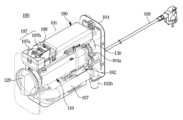
도 6은 도 1 및 도 4에 도시된 필터장치의 내부를 도시한다.
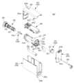
도 7은 도 6에 도시된 필터장치를 분해하여 도시한다.
도 8은 도 7에 도시된 필터장치를 도 7과 상이한 방향에서 도시한다.
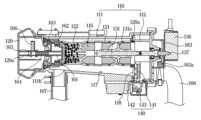
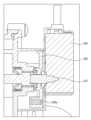
도 9는 도 6에 도시된 필터장치의 일부 구성의 단면을 도시한다.
도 10은 도 9에 도시된 필터 케이스로 유입되는 물이 필터를 통과하는 경우 구조를 도시한다.
도 11은 도 9에 도시된 필터가 막힌 경우, 물의 흐름을 도시한다.
도 12는 일 실시예에 따른 자성체 및 필터센서의 구조를 도시한다.
도 13은 도 12에 도시된 자성체 및 필터센서를 상이한 방향에서 도시한다.
도 14는 도 12에 도시된 자성체 및 필터센서를 상이한 방향에서 도시한다.
도 15는 일 실시예에 따른 필터장치의 구성들과 구성들 간의 신호 흐름을 간략하게 도시한다.
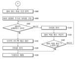
도 16은 일 실시예에 따른 필터장치의 제어방법의 순서도를 도시한다.
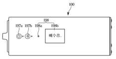
도 17은 일 실시예에 따른 필터장치의 상태 정보가 출력되는 모습의 일예를 도시한다.
도 18는 일 실시예에 따른 필터장치의 제어방법의 순서도를 도시한다.FIG. 1 illustrates a garment treatment device according to one embodiment.
Figure 2 illustrates a cross-section of the washing machine illustrated in Figure 1.
Figure 3 is a control block diagram of a washing machine according to one embodiment.
FIG. 4 illustrates a garment handling device according to one embodiment.
Figure 5 illustrates a cross-section of the washing machine illustrated in Figure 4.
Figure 6 illustrates the interior of the filter device illustrated in Figures 1 and 4.
Figure 7 is an exploded view of the filter device illustrated in Figure 6.
Figure 8 illustrates the filter device illustrated in Figure 7 from a different direction than Figure 7.
Fig. 9 illustrates a cross-section of a part of the filter device illustrated in Fig. 6.
Figure 10 illustrates the structure when water flowing into the filter case illustrated in Figure 9 passes through the filter.
Figure 11 illustrates the flow of water when the filter illustrated in Figure 9 is clogged.
Fig. 12 illustrates the structure of a magnetic body and filter sensor according to one embodiment.
Figure 13 illustrates the magnetic body and filter sensor illustrated in Figure 12 from different directions.
Figure 14 illustrates the magnetic body and filter sensor illustrated in Figure 12 from different directions.
FIG. 15 briefly illustrates the configurations of a filter device and the signal flow between the configurations according to one embodiment.
Fig. 16 illustrates a flow chart of a method for controlling a filter device according to one embodiment.
Fig. 17 illustrates an example of how status information of a filter device according to one embodiment is output.
Figure 18 illustrates a flow chart of a method for controlling a filter device according to one embodiment.
본 명세서에 기재된 실시예와 도면에 도시된 구성은 개시된 발명의 바람직한 일 예에 불과할 뿐이며, 본 출원의 출원시점에 있어서 본 명세서의 실시예와 도면을 대체할 수 있는 다양한 변형 예들이 있을 수 있다.The embodiments described in this specification and the configurations illustrated in the drawings are merely preferred examples of the disclosed invention, and there may be various modified examples that can replace the embodiments and drawings of this specification at the time of filing of the present application.
본 명세서에서 사용한 용어는 실시예를 설명하기 위해 사용된 것으로, 개시된 발명을 제한 및/또는 한정하려는 의도가 아니다.The terminology used herein is for the purpose of describing embodiments only and is not intended to limit and/or restrict the disclosed invention.
예를 들어, 본 명세서에서 단수의 표현은 문맥상 명백하게 다르게 뜻하지 않는 한, 복수의 표현을 포함할 수 있다.For example, in this specification, a singular expression may include a plural expression unless the context clearly indicates otherwise.
본 문서에서, "A 또는 B", "A 및 B 중 적어도 하나", "A 또는 B 중 적어도 하나", "A, B 또는 C", "A, B 및 C 중 적어도 하나", 및 "A, B, 또는 C 중 적어도 하나"와 같은 문구들 각각은 그 문구들 중 해당하는 문구에 함께 나열된 항목들 중 어느 하나, 또는 그들의 모든 가능한 조합을 포함할 수 있다.In this document, each of the phrases "A or B", "at least one of A and B", "at least one of A or B", "A, B, or C", "at least one of A, B, and C", and "at least one of A, B, or C" can include any one of the items listed together in that phrase, or all possible combinations of them.
"및/또는"이라는 용어는 복수의 관련된 기재된 구성요소들의 조합 또는 복수의 관련된 기재된 구성요소들 중의 어느 구성요소를 포함한다.The term "and/or" includes any combination of multiple related described elements or any one of multiple related described elements.
"제1", "제2", 또는 "첫째" 또는 "둘째"와 같은 용어들은 단순히 해당 구성요소를 다른 해당 구성요소와 구분하기 위해 사용될 수 있으며, 해당 구성요소들을 다른 측면(예: 중요성 또는 순서)에서 한정하지 않는다.Terms such as "first", "second", or "first" or "second" may be used merely to distinguish one component from another, and do not limit the components in any other respect (e.g., importance or order).
어떤(예: 제1) 구성요소가 다른(예: 제2) 구성요소에, "기능적으로" 또는 "통신적으로"라는 용어와 함께 또는 이런 용어 없이, "커플드" 또는 "커넥티드"라고 언급된 경우, 그것은 상기 어떤 구성요소가 상기 다른 구성요소에 직접적으로(예: 유선으로), 무선으로, 또는 제3 구성요소를 통하여 연결될 수 있다는 것을 의미한다.When a component (e.g., a first component) is referred to as being “coupled” or “connected” to another component (e.g., a second component), with or without the terms “functionally” or “communicatively,” it means that the component can be connected to the other component directly (e.g., wired), wirelessly, or through a third component.
"포함하다" 또는 "가지다"등의 용어는 본 문서에 기재된 특징, 숫자, 단계, 동작, 구성요소, 부품 또는 이들을 조합한 것이 존재함을 지정하려는 것이지, 하나 또는 그 이상의 다른 특징들이나 숫자, 단계, 동작, 구성요소, 부품 또는 이들을 조합한 것들의 존재 또는 부가 가능성을 미리 배제하지 않는다.The terms "include" or "have" and the like are intended to specify the presence of a feature, number, step, operation, component, part, or combination thereof described in this document, but do not exclude the presence or addition of one or more other features, numbers, steps, operations, components, parts, or combinations thereof.
어떤 구성요소가 다른 구성요소와 "연결", "결합", "지지" 또는 "접촉"되어 있다고 할 때, 이는 구성요소들이 직접적으로 연결, 결합, 지지 또는 접촉되는 경우뿐 아니라, 제3 구성요소를 통하여 간접적으로 연결, 결합, 지지 또는 접촉되는 경우를 포함한다.When a component is said to be “connected,” “coupled,” “supported,” or “contacted” with another component, this includes not only cases where the components are directly connected, coupled, supported, or in contact, but also cases where the components are indirectly connected, coupled, supported, or in contact through a third component.
어떤 구성요소가 다른 구성요소 "상에" 위치하고 있다고 할 때, 이는 어떤 구성요소가 다른 구성요소에 접해 있는 경우뿐 아니라 두 구성요소 사이에 또 다른 구성요소가 존재하는 경우도 포함한다.When we say that a component is "on" another component, this includes not only cases where the component is in contact with the other component, but also cases where there is another component between the two components.
또한, "~부", "~기", "~블록", "~부재", "~모듈" 등의 용어는 적어도 하나의 기능이나 동작을 처리하는 단위를 의미할 수 있다. 예를 들어, 상기 용어들은 FPGA (field-programmable gate array)/ ASIC (application specific integrated circuit) 등 적어도 하나의 하드웨어, 메모리에 저장된 적어도 하나의 소프트웨어 또는 프로세서에 의하여 처리되는 적어도 하나의 프로세스를 의미할 수 있다.Additionally, terms such as "~part", "~device", "~block", "~absence", and "~module" may refer to a unit that processes at least one function or operation. For example, the terms may refer to at least one hardware such as an FPGA (field-programmable gate array)/ASIC (application specific integrated circuit), at least one software stored in a memory, or at least one process processed by a processor.
다양한 실시예들에 따른 세탁기는 세탁, 헹굼, 배수 및 탈수 행정을 수행할 수 있다. 세탁기는 탈수가 완료된 세탁물에 대해 건조 행정를 수행할 수 있는 건조 겸용 세탁기일 수도 있다. 세탁기는 의류처리장치의 일 예일 수 있다. 의류처리장치는 의류(세탁대상물, 건조대상물)를 세탁하는 장치, 의류를 건조하는 장치, 의류의 세탁과 건조를 모두 수행할 수 있는 장치를 포함하는 개념이다.The washing machine according to various embodiments can perform washing, rinsing, draining, and dehydration processes. The washing machine may also be a washing machine with a dryer function that can perform a drying process on laundry that has completed dehydration. The washing machine may be an example of a clothing treatment device. The clothing treatment device is a concept that includes a device that washes clothing (a laundry object, a drying object), a device that dries clothing, and a device that can perform both washing and drying of clothing.
다양한 실시예들에 따른 세탁기는 세탁물을 투입하거나 인출하기 위한 투입구가 상방을 향하도록 마련되는 탑 로딩(top-loading) 세탁기 또는 세탁물을 투입하거나 인출하기 위한 투입구가 전방을 향하도록 마련되는 프런트 로딩(front-loading) 세탁기를 포함할 수 있다. 다양한 실시예들에 따른 세탁기는 탑 로딩 세탁기와 프런트 로딩 세탁기 이외의 다른 로딩 방식의 세탁기를 포함할 수 있다.Washing machines according to various embodiments may include top-loading washing machines in which an inlet for putting in or taking out laundry is provided to face upward, or front-loading washing machines in which an inlet for putting in or taking out laundry is provided to face forward. Washing machines according to various embodiments may include washing machines of other loading methods than top-loading washing machines and front-loading washing machines.
탑 로딩 세탁기의 경우, 펄세이터와 같은 회전체에 의해 발생하는 수류를 이용하여 세탁물을 세탁할 수 있다. 프런트 로딩 세탁기의 경우, 드럼을 회전시켜 세탁물의 상승과 낙하를 반복함으로써 세탁물을 세탁할 수 있다. 프런트 로딩 세탁기의 경우, 세탁물을 상승시키기 위한 리프트를 포함할 수 있다. 프런트 로딩 세탁기는 드럼의 내부에 수용된 세탁물을 건조할 수 있는 건조 겸용 세탁기를 포함할 수 있다. 건조 겸용 세탁기는 고온의 공기를 위한 가열 장치를 포함할 수 있다. 건조 겸용 세탁기는 건조한 공기를 위한 응축 장치를 더 포함할 수 있다. 일 예로, 건조 겸용 세탁기는 히트 펌프를 포함할 수 있다. 다양한 실시예들에 따른 세탁기는 상술한 세탁 방식 이외의 다른 세탁 방식의 세탁기를 포함할 수 있다.In the case of a top-loading washing machine, laundry can be washed using a water current generated by a rotating body such as a pulsator. In the case of a front-loading washing machine, laundry can be washed by rotating a drum to repeatedly raise and lower the laundry. In the case of a front-loading washing machine, a lift for raising the laundry can be included. The front-loading washing machine can include a washing machine with a dryer capable of drying the laundry accommodated inside the drum. The washing machine with a dryer can include a heating device for high-temperature air. The washing machine with a dryer can further include a condensing device for dry air. As an example, the washing machine with a dryer can include a heat pump. The washing machine according to various embodiments can include a washing machine with a washing method other than the washing method described above.
이하에서는 첨부된 도면을 참조하여 다양한 실시예에 따른 세탁기를 구체적으로 설명한다.Below, washing machines according to various embodiments are specifically described with reference to the attached drawings.
도 1은 일 실시예에 따른 의류 처리 장치를 도시한다. 도 2는 도 1에 도시된 세탁기의 단면을 도시한다.FIG. 1 illustrates a garment treatment device according to one embodiment. FIG. 2 illustrates a cross-section of the washing machine illustrated in FIG. 1.
도 1 및 도 2에 도시된 바와 같이, 의류 처리 장치(1)의 세탁기(10)는 내부에 각종 구성품을 수용하는 세탁기 하우징(11)을 포함할 수 있다. 세탁기 하우징(11)은 세탁기(10)의 외관을 형성할 수 있다. 세탁기 하우징(11)은 일 부분이 개방된 상자 형상을 가질 수 있다.As shown in FIG. 1 and FIG. 2, the washing machine (10) of the clothing treatment device (1) may include a washing machine housing (11) that accommodates various components therein. The washing machine housing (11) may form the exterior of the washing machine (10). The washing machine housing (11) may have a box shape with one portion open.
세탁기 하우징(11)은 드럼(30)의 내부에 접근 가능하도록 형성되는 하우징 개구(12)를 포함할 수 있다. 하우징 개구(12)는 대략 전방을 향해 개방될 수 있다.The washing machine housing (11) may include a housing opening (12) formed to allow access to the interior of the drum (30). The housing opening (12) may be opened approximately toward the front.
세탁기(10)는 세탁기 하우징(11)에 마련되는 하우징 개구(12)를 개폐하기 위한 도어(13)를 포함할 수 있다. 도어(13)는 힌지(14)에 의해 세탁기 하우징(11)에 회전 가능하게 장착될 수 있다. 도어(13)의 적어도 일 부분은 세탁기 하우징(11)의 내부가 보이도록 투명 또는 반투명하게 마련될 수 있다.The washing machine (10) may include a door (13) for opening and closing a housing opening (12) provided in the washing machine housing (11). The door (13) may be rotatably mounted to the washing machine housing (11) by a hinge (14). At least a portion of the door (13) may be provided to be transparent or translucent so that the inside of the washing machine housing (11) may be visible.
세탁기(10)는 물을 저수하도록 세탁기 하우징(11)의 내부에 마련되는 터브(20)를 포함할 수 있다. 터브(20)는 세탁기 하우징(11)의 내부에 배치될 수 있다. 터브(20)는 하우징 개구(12)에 대응되도록 마련되는 터브 개구(22)를 포함할 수 있다. 터브 개구(22)는 대략 전방을 향해 개방될 수 있다. 터브(20)는 세탁기 하우징(11)의 내부에 지지될 수 있다. 터브(20)는 일 측이 개방된 대략 원통 형상을 가질 수 있다.The washing machine (10) may include a tub (20) provided inside the washing machine housing (11) to store water. The tub (20) may be arranged inside the washing machine housing (11). The tub (20) may include a tub opening (22) provided to correspond to the housing opening (12). The tub opening (22) may be opened approximately forward. The tub (20) may be supported inside the washing machine housing (11). The tub (20) may have an approximately cylindrical shape with one side being open.
터브(20)는 댐퍼(80)에 의해 세탁기 하우징(11)으로부터 탄력적으로 지지될 수 있다. 댐퍼(80)는 세탁기 하우징(11)과 터브(20)를 연결할 수 있다. 댐퍼(80)는 드럼(30)의 회전 시 발생하는 진동이 터브(20) 및/또는 세탁기 하우징(11)으로 전달될 때, 터브(20) 및 세탁기 하우징(11) 사이에서 진동에너지를 흡수하여 진동을 감쇄시키도록 마련될 수 있다.The tub (20) can be elastically supported from the washing machine housing (11) by a damper (80). The damper (80) can connect the washing machine housing (11) and the tub (20). The damper (80) can be provided to absorb vibration energy between the tub (20) and the washing machine housing (11) to attenuate the vibration when the vibration generated when the drum (30) rotates is transmitted to the tub (20) and/or the washing machine housing (11).
세탁기(10)는 세탁물을 수용하도록 마련되는 드럼(30)을 포함할 수 있다. 드럼(30)은 터브(20)의 내부에 회전 가능하게 마련될 수 있다. 드럼(30)은 터브(20) 내부에서 회전하면서 세탁, 헹굼, 및/또는 탈수를 수행할 수 있다. 드럼(30)은 드럼(30)의 내부 공간과 터브(20)의 내부 공간을 연결하는 통공(34)을 포함할 수 있다. 드럼(30)은 일 측이 개방된 대략 원통 형상을 가질 수 있다. 드럼(30)의 내주면에는 드럼(30)이 회전할 때 세탁물의 상승 및 낙하가 이루어질 수 있도록 적어도 하나의 리프터(35)가 설치될 수 있다.The washing machine (10) may include a drum (30) provided to accommodate laundry. The drum (30) may be provided rotatably inside the tub (20). The drum (30) may perform washing, rinsing, and/or dehydration while rotating inside the tub (20). The drum (30) may include a hole (34) connecting the internal space of the drum (30) and the internal space of the tub (20). The drum (30) may have a generally cylindrical shape with one side open. At least one lifter (35) may be installed on the inner surface of the drum (30) so that laundry may be raised and lowered when the drum (30) rotates.
드럼(30)은 하우징 개구(12) 및 터브 개구(22)에 대응되도록 마련되는 드럼 개구(32)를 포함할 수 있다. 세탁물은 하우징 개구(12), 터브 개구(22), 및 드럼 개구(32)를 통해 드럼(30)에 투입되거나, 드럼(30)으로부터 인출될 수 있다.The drum (30) may include a drum opening (32) provided to correspond to the housing opening (12) and the tub opening (22). Laundry may be fed into the drum (30) or taken out from the drum (30) through the housing opening (12), the tub opening (22), and the drum opening (32).
세탁기(10)는 드럼(30)을 회전시키도록 구성되는 세탁기 구동장치(40)를 포함할 수 있다. 세탁기 구동장치(40)는 구동모터(41)와, 구동모터(41)에서 발생된 구동력을 드럼(30)에 전달하기 위한 회전 샤프트(42)를 포함할 수 있다. 회전 샤프트(42)는 터브(20)를 관통하여 드럼(30)에 연결될 수 있다.The washing machine (10) may include a washing machine drive device (40) configured to rotate a drum (30). The washing machine drive device (40) may include a drive motor (41) and a rotation shaft (42) for transmitting a driving force generated from the drive motor (41) to the drum (30). The rotation shaft (42) may be connected to the drum (30) by penetrating the tub (20).
세탁기(10)는 회전 샤프트(42)가 구동모터(41)에 직접 연결되어 드럼(30)을 회전시키는 직접 구동 타입과 구동모터(41)와 회전 샤프트(42) 사이에 풀리(43)를 연결하여 드럼(30)을 구동시키는 간접 구동 타입으로 구분될 수 있다.The washing machine (10) can be divided into a direct drive type in which a rotating shaft (42) is directly connected to a driving motor (41) to rotate a drum (30) and an indirect drive type in which a pulley (43) is connected between a driving motor (41) and a rotating shaft (42) to drive a drum (30).
일 실시예에 따른 세탁기(10)는 간접 구동 타입으로 마련될 수 있지만, 이에 제한되지 않고, 직접 구동 타입으로 마련될 수도 있다.The washing machine (10) according to one embodiment may be provided as an indirect drive type, but is not limited thereto and may also be provided as a direct drive type.
회전 샤프트(42)는 일 단이 드럼(30)에 연결되고, 타 단이 구동모터(41)로부터 동력을 전달받기 위해 풀리(43)에 연결될 수 있다. 구동모터(41)의 회전 축에는 모터 풀리(41a)가 형성될 수 있다. 모터 풀리(41a)와 풀리(43) 사이에는 구동 벨트(44)가 마련되어 구동 벨트(44)에 의해 회전 샤프트(42)가 구동할 수 있다.The rotary shaft (42) may be connected at one end to the drum (30) and at the other end to a pulley (43) to receive power from a driving motor (41). A motor pulley (41a) may be formed on the rotating shaft of the driving motor (41). A driving belt (44) may be provided between the motor pulley (41a) and the pulley (43), so that the rotary shaft (42) may be driven by the driving belt (44).
터브(20)의 후측 일부에는 회전 샤프트(42)를 회전 가능하게 지지하도록 베어링 하우징(45)이 설치될 수 있다. 베어링 하우징(45)은 알루미늄 합금으로 마련될 수 있으며, 터브(20)를 사출 성형할 때 터브(20)의 후측 일부에 인서트될 수 있다.A bearing housing (45) may be installed on a rear portion of the tub (20) to rotatably support a rotating shaft (42). The bearing housing (45) may be made of an aluminum alloy and may be inserted into a rear portion of the tub (20) when the tub (20) is injection molded.
세탁기 구동장치(40)는 드럼(30)을 정회전 또는 역회전시켜 세탁, 헹굼, 및/또는 탈수, 또는 건조 동작을 수행할 수 있도록 마련될 수 있다.The washing machine driving device (40) may be provided to perform washing, rinsing, and/or dehydration, or drying operations by rotating the drum (30) forward or reverse.
세탁기(10)는 급수장치(50)를 포함할 수 있다. 급수장치(50)는 터브(20)에 물을 공급할 수 있다. 급수장치(50)는 터브(20)의 상측에 위치할 수 있다. 급수장치(50)는 급수관(51)과, 급수관(51)에 마련되는 급수밸브(56)를 포함할 수 있다. 급수관(51)은 외부 급수원과 연결될 수 있다. 급수관(51)은 외부 급수원으로부터 세제 공급장치(60) 및/또는 터브(20)까지 연장될 수 있다. 물은 세제 공급장치(60)를 거쳐 터브(20)로 공급될 수 있다. 물은 세제 공급장치(60)를 경유하지 않고 터브(20)로 공급될 수 있다.The washing machine (10) may include a water supply device (50). The water supply device (50) may supply water to the tub (20). The water supply device (50) may be located on the upper side of the tub (20). The water supply device (50) may include a water supply pipe (51) and a water supply valve (56) provided in the water supply pipe (51). The water supply pipe (51) may be connected to an external water source. The water supply pipe (51) may extend from the external water source to a detergent supply device (60) and/or the tub (20). Water may be supplied to the tub (20) via the detergent supply device (60). Water may be supplied to the tub (20) without passing through the detergent supply device (60).
급수밸브(56)는 제어부(90)의 전기적 신호에 응답하여 급수관(51)을 개방하거나 폐쇄할 수 있다. 급수밸브(56)는 외부 급수원으로부터 터브(20)로 물이 공급되는 것을 허용하거나 차단할 수 있다. 급수밸브(56)는, 예를 들면, 전기적 신호에 응답하여 개폐되는 솔레노이드 밸브(solenoid valve)를 포함할 수 있다.The water supply valve (56) can open or close the water supply pipe (51) in response to an electrical signal from the control unit (90). The water supply valve (56) can allow or block the supply of water from an external water source to the tub (20). The water supply valve (56) can include, for example, a solenoid valve that opens and closes in response to an electrical signal.
세탁기(10)는 터브(20)로 세제를 공급하도록 구성되는 세제 공급장치(60)를 포함할 수 있다. 세제 공급장치(60)는 급수과정에서 터브(20) 내부로 세제를 공급하도록 구성될 수 있다. 급수관(51)을 통해 공급되는 물은 세제 공급장치(60)를 경유하여 세제와 혼합될 수 있다. 세제와 혼합된 물은 터브(20)의 내부로 공급될 수 있다. 세제는 세탁용 세제뿐 아니라 건조기용 린스, 탈취제, 살균제 또는 방향제 등을 포함할 수 있다. 세제 공급장치(60)는 연결관(61)을 통해 터브(20)와 연결될 수 있다.The washing machine (10) may include a detergent supply device (60) configured to supply detergent to the tub (20). The detergent supply device (60) may be configured to supply detergent into the tub (20) during the water supply process. Water supplied through the water supply pipe (51) may be mixed with detergent via the detergent supply device (60). The water mixed with the detergent may be supplied into the tub (20). The detergent may include not only a laundry detergent but also a dryer rinse, a deodorizer, a sterilizer, or an air freshener. The detergent supply device (60) may be connected to the tub (20) through a connection pipe (61).
세탁기(10)는 배수장치(70)를 포함할 수 있다. 배수장치(70)는 터브(20)에 수용된 물을 외부로 배출하도록 구성될 수 있다. 배수장치(70)는 터브(20)의 물을 세탁기 하우징(11)의 외부로 배출하기 위한 배수펌프(73)와, 터브(20) 내부의 물이 배수펌프(73)로 유입될 수 있도록 터브(20)와 배수펌프(73)를 연결하는 연결호스(71)와, 배수펌프(73)에 의해 펌핑된 물을 세탁기 하우징(11)의 외부로 안내하는 배수호스(74)를 포함할 수 있다. 배수장치(70)는 연결호스(71)를 개폐하도록 연결호스(71)에 마련되는 배수밸브(72)를 포함할 수 있다.The washing machine (10) may include a drainage device (70). The drainage device (70) may be configured to discharge water contained in the tub (20) to the outside. The drainage device (70) may include a drainage pump (73) for discharging water in the tub (20) to the outside of the washing machine housing (11), a connection hose (71) for connecting the tub (20) and the drainage pump (73) so that water inside the tub (20) may flow into the drainage pump (73), and a drainage hose (74) for guiding water pumped by the drainage pump (73) to the outside of the washing machine housing (11). The drainage device (70) may include a drainage valve (72) provided in the connection hose (71) for opening and closing the connection hose (71).
세탁기(10)는 사용자와 세탁기(10)가 상호 작용하기 위한 사용자 인터페이스 장치(15)를 제공할 수 있다.The washing machine (10) may provide a user interface device (15) for interaction between the user and the washing machine (10).
세탁기(10)는 적어도 하나의 사용자 인터페이스 장치(15)를 포함할 수 있다. 사용자 인터페이스 장치(15)는 적어도 하나의 입력 인터페이스(16)와 적어도 하나의 출력 인터페이스(17)를 포함할 수 있다.The washing machine (10) may include at least one user interface device (15). The user interface device (15) may include at least one input interface (16) and at least one output interface (17).
적어도 하나의 입력 인터페이스(16)는 사용자로부터 수신된 감각 정보(sensory information)를 전기적인 신호로 전환할 수 있다.At least one input interface (16) can convert sensory information received from a user into an electrical signal.
적어도 하나의 입력 인터페이스(16)는 전원 버튼과, 동작 버튼과, 코스 선택 다이얼(또는 코스 선택 버튼)과, 세탁/헹굼/탈수 설정 버튼을 포함할 수 있다. 적어도 하나의 입력 인터페이스(16)는, 예를 들어, 택트 스위치(tact switch), 푸시 스위치, 슬라이드 스위치, 토클 스위치, 마이크로 스위치, 터치 스위치, 터치 패드, 터치 스크린, 조그 다이얼, 및/또는 마이크로폰 등을 포함할 수 있다.At least one input interface (16) may include a power button, an operation button, a course selection dial (or a course selection button), and a wash/rinse/spin setting button. The at least one input interface (16) may include, for example, a tact switch, a push switch, a slide switch, a toggle switch, a micro switch, a touch switch, a touch pad, a touch screen, a jog dial, and/or a microphone.
적어도 하나의 출력 인터페이스(17)는 감각 정보를 생성함으로써 사용자에게 세탁기(10)의 동작에 관련된 다양한 정보를 전달할 수 있다.At least one output interface (17) can transmit various information related to the operation of the washing machine (10) to the user by generating sensory information.
예를 들어, 적어도 하나의 출력 인터페이스(17)는 세탁 코스 및 세탁기(10)의 동작 시간, 세탁 설정/헹굼 설정/탈수 설정에 관련된 정보를 사용자에게 전달할 수 있다. 세탁기(10) 동작에 관한 정보는 스크린, 인디케이터, 음성 등으로 출력될 수 있다. 적어도 하나의 출력 인터페이스(17)는, 예를 들어, 액정 디스플레이(Liquid Crystal Display, LCD) 패널, 발광 다이오드(Light Emitting Diode, LED) 패널, 발광 다이오드(Light Emitting Diode, LED) 모듈, 스피커 등을 포함할 수 있다.For example, at least one output interface (17) can transmit information related to a washing course and an operating time of the washing machine (10), washing settings/rinsing settings/spin settings to a user. Information related to the operation of the washing machine (10) can be output by a screen, an indicator, a voice, etc. At least one output interface (17) can include, for example, a liquid crystal display (LCD) panel, a light emitting diode (LED) panel, a light emitting diode (LED) module, a speaker, etc.
의류 처리 장치(1)는 세탁기(10)의 배수장치(70)와 연결 가능하도록 마련되는 필터장치(100)를 포함할 수 있다. 일 예로, 필터장치(100)는 배수호스(74)와 연결 가능하도록 마련될 수 있다.The clothing treatment device (1) may include a filter device (100) that is provided to be connected to a drain device (70) of a washing machine (10). For example, the filter device (100) may be provided to be connected to a drain hose (74).
필터장치(100)는 세탁기(10)의 외부에 배치될 수 있다. 일 예로, 필터장치(100)는 세탁기 하우징(11)의 외부에 마련될 수 있다. 필터장치(100)는 세탁기(10)로부터 배출되는 물로부터 이물질을 여과하도록 마련될 수 있다. 필터장치(100)는 세탁기(10)에서 여과 가능한 이물질의 크기보다 작은 크기의 이물질을 여과 가능하도록 마련될 수 있다. 일 예로, 필터장치(100)는 세탁기(10)의 배수장치(70)에서 여과 가능한 이물질의 크기보다 작은 크기의 이물질을 여과 가능하도록 마련될 수 있다.The filter device (100) may be placed outside the washing machine (10). For example, the filter device (100) may be provided outside the washing machine housing (11). The filter device (100) may be provided to filter foreign substances from water discharged from the washing machine (10). The filter device (100) may be provided to filter foreign substances having a size smaller than the size of foreign substances that can be filtered in the washing machine (10). For example, the filter device (100) may be provided to filter foreign substances having a size smaller than the size of foreign substances that can be filtered in the drainage device (70) of the washing machine (10).
도 3은 일 실시예에 따른 세탁기의 제어 블록도이다.Figure 3 is a control block diagram of a washing machine according to one embodiment.
일 실시에에서, 세탁기(10)는 사용자 인터페이스 장치(15)와, 구동장치(40)와, 급수장치(50)와, 배수장치(70)와, 센서부(95)와, 통신 모듈(96)과, 제어부(90)를 포함할 수 있다.In one embodiment, the washing machine (10) may include a user interface device (15), a driving device (40), a water supply device (50), a drainage device (70), a sensor unit (95), a communication module (96), and a control unit (90).
사용자 인터페이스 장치(15)는 사용자와 세탁기(10)가 상호 작용하기 위한 사용자 인터페이스를 제공할 수 있다.The user interface device (15) can provide a user interface for interaction between a user and a washing machine (10).
사용자 인터페이스 장치(15)는 적어도 하나의 입력 인터페이스(16)와 적어도 하나의 출력 인터페이스(17)를 포함할 수 있다.The user interface device (15) may include at least one input interface (16) and at least one output interface (17).
적어도 하나의 입력 인터페이스(16)는 사용자로부터 수신된 감각 정보(sensory information)를 전기적인 신호로 전환할 수 있다.At least one input interface (16) can convert sensory information received from a user into an electrical signal.
적어도 하나의 입력 인터페이스(16)는 전원 버튼과, 동작 버튼과, 코스 선택 다이얼(또는 코스 선택 버튼)과, 세탁/헹굼/탈수 설정 버튼을 포함할 수 있다. 적어도 하나의 입력 인터페이스(16)는, 예를 들어, 택트 스위치(tact switch), 푸시 스위치, 슬라이드 스위치, 토클 스위치, 마이크로 스위치, 터치 스위치, 터치 패드, 터치 스크린, 조그 다이얼, 및/또는 마이크로폰 등을 포함할 수 있다.At least one input interface (16) may include a power button, an operation button, a course selection dial (or a course selection button), and a wash/rinse/spin setting button. The at least one input interface (16) may include, for example, a tact switch, a push switch, a slide switch, a toggle switch, a micro switch, a touch switch, a touch pad, a touch screen, a jog dial, and/or a microphone.
적어도 하나의 출력 인터페이스(17)는 감각 정보를 생성함으로써 사용자에게 세탁기(10)의 동작에 관련된 다양한 데이터를 전달할 수 있다.At least one output interface (17) can transmit various data related to the operation of the washing machine (10) to the user by generating sensory information.
예를 들어, 적어도 하나의 출력 인터페이스(17)는 세탁 코스 및 세탁기(10)의 동작 시간, 세탁 설정/헹굼 설정/탈수 설정에 관련된 정보를 사용자에게 전달할 수 있다. 세탁기(10) 동작에 관한 정보는 스크린, 인디케이터, 음성 등으로 출력될 수 있다. 세탁기(10) 동작에 관한 정보는 디스플레이를 통해 출력될 수 있다. 적어도 하나의 출력 인터페이스(17)는, 예를 들어, 액정 디스플레이(Liquid Crystal Display, LCD) 패널, 발광 다이오드(Light Emitting Diode, LED) 패널, 스피커 등을 포함할 수 있다.For example, at least one output interface (17) can transmit information related to a washing course and an operating time of the washing machine (10), washing settings/rinsing settings/spin settings to the user. Information related to the operation of the washing machine (10) can be output through a screen, an indicator, a voice, etc. Information related to the operation of the washing machine (10) can be output through a display. At least one output interface (17) can include, for example, a liquid crystal display (LCD) panel, a light emitting diode (LED) panel, a speaker, etc.
구동장치(40)는 드럼(30)을 회전시키기 위한 구동력을 제공하는 구동모터(41)를 포함할 수 있다. 구동장치(40)는 제어부(90)의 제어 신호에 기초하여 동작할 수 있다.The driving device (40) may include a driving motor (41) that provides driving force to rotate the drum (30). The driving device (40) may operate based on a control signal from the control unit (90).
급수장치(50)는 외부 급수원으로부터 세제 공급장치(60) 및/또는 터브(20)까지 연장되는 급수관(51)을 개폐하는 급수밸브(56)를 포함할 수 있다. 급수밸브(56)는 제어부(90)의 제어 신호에 기초하여 개폐될 수 있다.The water supply device (50) may include a water supply valve (56) that opens and closes a water supply pipe (51) extending from an external water source to the detergent supply device (60) and/or the tub (20). The water supply valve (56) may be opened and closed based on a control signal from the control unit (90).
배수장치(70)는 터브(20)의 물을 세탁기 하우징(11)의 외부로 배출하기 위한 배수펌프(73)를 포함할 수 있다. 배수펌프(73)는 제어부(90)의 제어 신호에 기초하여 동작할 수 있다.The drain device (70) may include a drain pump (73) for discharging water from the tub (20) to the outside of the washing machine housing (11). The drain pump (73) may operate based on a control signal from the control unit (90).
센서부(95)는 세탁기(10)의 동작 상태와 관련된 정보를 획득하는 적어도 하나의 센서를 포함할 수 있다.The sensor unit (95) may include at least one sensor that obtains information related to the operating status of the washing machine (10).
예를 들어, 센서부(95)는 터브의 수위를 감지하는 수위센서, 구동장치(40)의 동작 상태를 감지하는 센서, 급수장치(50)를 통해 터브(20)로 유입되는 유량을 감지하는 유량센서 또는 배수장치(70)의 동작 상태를 감지하는 센서 중 적어도 하나를 포함할 수 있다.For example, the sensor unit (95) may include at least one of a water level sensor that detects the water level of the tub, a sensor that detects the operating status of the driving device (40), a flow rate sensor that detects the amount of water flowing into the tub (20) through the water supply device (50), or a sensor that detects the operating status of the drainage device (70).
구동장치(40)의 동작 상태를 감지하는 센서는, 일 예로, 구동모터(41)로 인가되는 구동전류를 측정하는 전류센서를 포함할 수 있으나, 이에 한정되는 것은 아니다.The sensor that detects the operating status of the driving device (40) may include, for example, a current sensor that measures the driving current applied to the driving motor (41), but is not limited thereto.
배수장치(70)의 동작 상태를 감지하는 센서는, 일 예로, 배수펌프(73)로 인가되는 구동전류를 측정하는 전류센서를 포함할 수 있으나, 이에 한정되는 것은 아니다.A sensor that detects the operating status of the drainage device (70) may include, for example, a current sensor that measures the driving current applied to the drainage pump (73), but is not limited thereto.
세탁기(10)는 외부장치(예: 서버, 사용자 기기, 가전기기, 및/또는 필터장치(100))와 유선 및/또는 무선으로 통신하기 위한 통신 모듈(96)을 포함할 수 있다.The washing machine (10) may include a communication module (96) for communicating with an external device (e.g., a server, a user device, an appliance, and/or a filter device (100)) via wired and/or wireless means.
통신 모듈(96)은 근거리 통신 모듈 또는 원거리 통신 모듈 중 적어도 하나를 포함할 수 있다.The communication module (96) may include at least one of a short-range communication module or a long-range communication module.
통신 모듈(96)은 외부장치에 데이터를 전송하거나, 외부장치로부터 데이터를 수신할 수 있다. 예를 들어, 통신 모듈(96)은 필터장치(100), 서버, 사용자 기기 및/또는 다른 가전기기와 통신을 수립하고, 각종 데이터를 송수신할 수 있다.The communication module (96) can transmit data to an external device or receive data from an external device. For example, the communication module (96) can establish communication with a filter device (100), a server, a user device, and/or other home appliances, and transmit and receive various data.
이를 위해, 통신 모듈(96)은 외부장치 간의 직접(예: 유선) 통신 채널 또는 무선 통신 채널의 수립, 및 수립된 통신 채널을 통한 통신 수행을 지원할 수 있다. 일 실시예에 따르면, 통신 모듈(96)은 무선 통신 모듈(예: 셀룰러 통신 모듈, 근거리 무선 통신 모듈, 또는 GNSS(global navigation satellite system) 통신 모듈) 또는 유선 통신 모듈(예: LAN(local area network) 통신 모듈, 또는 전력선 통신 모듈)을 포함할 수 있다. 이들 통신 모듈 중 해당하는 통신 모듈은 제 1 네트워크(예: 블루투스, WiFi(wireless fidelity) direct 또는 IrDA(infrared data association)와 같은 근거리 통신 네트워크) 또는 제 2 네트워크(예: 레거시 셀룰러 네트워크, 5G 네트워크, 차세대 통신 네트워크, 인터넷, 또는 컴퓨터 네트워크(예: LAN 또는 WAN)와 같은 원거리 통신 네트워크)를 통하여 외부장치와 통신할 수 있다. 이런 여러 종류의 통신 모듈들은 하나의 구성요소(예: 단일 칩)로 통합되거나, 또는 서로 별도의 복수의 구성요소들(예: 복수 칩들)로 구현될 수 있다.To this end, the communication module (96) may support establishment of a direct (e.g., wired) communication channel or a wireless communication channel between external devices, and performance of communication through the established communication channel. According to one embodiment, the communication module (96) may include a wireless communication module (e.g., a cellular communication module, a short-range wireless communication module, or a GNSS (global navigation satellite system) communication module) or a wired communication module (e.g., a local area network (LAN) communication module, or a power line communication module). A corresponding communication module among these communication modules may communicate with the external device through a first network (e.g., a short-range communication network such as Bluetooth, WiFi (wireless fidelity) direct, or IrDA (infrared data association)) or a second network (e.g., a long-range communication network such as a legacy cellular network, a 5G network, a next-generation communication network, the Internet, or a computer network (e.g., a LAN or WAN)). These different types of communication modules may be integrated into a single component (e.g., a single chip) or implemented as multiple separate components (e.g., multiple chips).
근거리 통신 모듈(short-range wireless communication module)은 블루투스 통신 모듈, BLE(Bluetooth Low Energy) 통신 모듈, 근거리 무선 통신 모듈(Near Field Communication module), WLAN(와이파이) 통신 모듈, 지그비(Zigbee) 통신 모듈, 적외선(IrDA, infrared Data Association) 통신 모듈, WFD(Wi-Fi Direct) 통신 모듈, UWB(ultrawideband) 통신 모듈, Ant+ 통신 모듈, 마이크로 웨이브(uWave) 통신 모듈 등을 포함할 수 있으나, 이에 한정되는 것은 아니다.A short-range wireless communication module may include, but is not limited to, a Bluetooth communication module, a BLE (Bluetooth Low Energy) communication module, a Near Field Communication module, a WLAN (Wi-Fi) communication module, a Zigbee communication module, an infrared (IrDA, infrared Data Association) communication module, a WFD (Wi-Fi Direct) communication module, a UWB (ultrawideband) communication module, an Ant+ communication module, a microwave (uWave) communication module, etc.
원거리 통신 모듈은, 다양한 종류의 원거리 통신을 수행하는 통신 모듈을 포함할 수 있으며, 이동 통신부를 포함할 수 있다. 이동 통신부는 이동 통신망 상에서 기지국, 외부의 단말, 서버 중 적어도 하나와 무선 신호를 송수신한다.The long-distance communication module may include a communication module that performs various types of long-distance communication and may include a mobile communication unit. The mobile communication unit transmits and receives a wireless signal with at least one of a base station, an external terminal, and a server on a mobile communication network.
일 실시예에서, 통신 모듈(96)은 주변의 접속 중계기(AP: Access point)를 통해 서버, 사용자 기기, 다른 가전 기기 등의 외부장치와 통신할 수 있다. 접속 중계기(AP)는 세탁기(10), 필터장치(100) 및/또는 사용자 기기가 연결된 지역 네트워크(LAN)를 서버가 연결된 광역 네트워크(WAN)에 연결시킬 수 있다. 필터장치(100), 세탁기(10) 및/또는 사용자 기기는 광역 네트워크(WAN)를 통해 서버에 연결될 수 있다.In one embodiment, the communication module (96) can communicate with external devices such as a server, a user device, and other home appliances through a peripheral access point (AP). The access point (AP) can connect a local area network (LAN) to which the washing machine (10), the filter device (100), and/or the user device are connected to a wide area network (WAN) to which the server is connected. The filter device (100), the washing machine (10), and/or the user device can be connected to the server through the wide area network (WAN).
제어부(90)는 세탁기(10)의 각종 구성 요소(예: 구동장치(40), 급수장치(50), 배수장치(70))를 제어할 수 있다. 제어부(90)는 사용자 입력에 따라 급수, 세탁, 헹굼, 및/또는 탈수 등을 포함하는 적어도 하나의 행정을 수행하도록 세탁기(10)의 각종 구성 요소를 제어할 수 있다. 예를 들어, 제어부(90)는 드럼(30)의 회전 속도를 조절하도록 구동장치(40)의 구동모터(41)를 제어하거나, 터브(20)로 물을 공급하도록 급수장치(50)의 급수밸브(56)를 제어하거나, 터브(20)의 물을 외부로 배출하도록 배수장치(70)의 배수펌프(73)를 제어할 수 있다.The control unit (90) can control various components of the washing machine (10) (e.g., driving unit (40), water supply unit (50), drain unit (70)). The control unit (90) can control various components of the washing machine (10) to perform at least one operation including water supply, washing, rinsing, and/or dehydration according to user input. For example, the control unit (90) can control the driving motor (41) of the driving unit (40) to adjust the rotation speed of the drum (30), control the water supply valve (56) of the water supply unit (50) to supply water to the tub (20), or control the drain pump (73) of the drain unit (70) to discharge water in the tub (20) to the outside.
제어부(90)는 CPU나, Micom이나, 메모리 등의 하드웨어와, 제어 프로그램 등의 소프트웨어를 포함할 수 있다. 예를 들어, 제어부(90)는 세탁기(10) 내 구성요소들의 동작을 제어하기 위한 알고리즘, 프로그램 형태의 데이터를 저장하는 적어도 하나의 메모리(92), 및 적어도 하나의 메모리(92)에 저장된 데이터를 이용하여 전술한 동작 및 후술할 동작을 수행하는 적어도 하나의 프로세서(91)를 포함할 수 있다. 메모리(92)와 프로세서(91)는 각각 별개의 칩으로 구현될 수 있다. 프로세서(91)는 1 또는 2이상의 프로세서 칩을 포함하거나 또는 1 또는 2이상의 프로세싱 코어를 포함할 수 있다. 메모리(92)는 1 또는 2이상의 메모리 칩을 포함하거나 또는 1 또는 2이상의 메모리 블록을 포함할 수 있다. 또한, 메모리(92)와 프로세서(91)는 단일 칩으로 구현될 수도 있다.The control unit (90) may include hardware such as a CPU, Micom, or memory, and software such as a control program. For example, the control unit (90) may include at least one memory (92) storing data in the form of an algorithm and a program for controlling the operation of components in the washing machine (10), and at least one processor (91) performing the operations described above and the operations to be described below using the data stored in the at least one memory (92). The memory (92) and the processor (91) may each be implemented as separate chips. The processor (91) may include one or more processor chips or one or more processing cores. The memory (92) may include one or more memory chips or one or more memory blocks. In addition, the memory (92) and the processor (91) may be implemented as a single chip.
도 4는 일 실시예에 따른 의류 처리 장치를 도시한다. 도 5는 도 4에 도시된 세탁기의 단면을 도시한다.Fig. 4 illustrates a garment treatment device according to one embodiment. Fig. 5 illustrates a cross-section of the washing machine illustrated in Fig. 4.
도 4 및 도 5에 도시된 바와 같이, 의류 처리 장치(1a)의 세탁기(10a)는 내부에 각종 구성품을 수용하는 하우징(11a)을 포함할 수 있다. 하우징(11a)은 세탁기(10a)의 외관을 형성할 수 있다. 하우징(11a)은 일 부분이 개방된 상자 형상을 가질 수 있다.As shown in FIG. 4 and FIG. 5, the washing machine (10a) of the clothing treatment device (1a) may include a housing (11a) that accommodates various components therein. The housing (11a) may form the exterior of the washing machine (10a). The housing (11a) may have a box shape with one portion open.
하우징(11a)은 드럼(30a)의 내부에 접근 가능하도록 형성되는 하우징 개구(12a)를 포함할 수 있다. 하우징 개구(12a)는 대략 상측을 향해 개방될 수 있다.The housing (11a) may include a housing opening (12a) formed to allow access to the interior of the drum (30a). The housing opening (12a) may be opened approximately upwardly.
세탁기(10a)는 하우징(11a)에 마련되는 하우징 개구(12a)를 개폐하기 위한 도어(13a)를 포함할 수 있다. 도어(13a)는 힌지에 의해 하우징(11a)에 회전 가능하게 장착될 수 있다. 도어(13a)의 적어도 일 부분은 하우징(11a)의 내부가 보이도록 투명 또는 반투명하게 마련될 수 있다.The washing machine (10a) may include a door (13a) for opening and closing a housing opening (12a) provided in the housing (11a). The door (13a) may be rotatably mounted to the housing (11a) by a hinge. At least a portion of the door (13a) may be provided to be transparent or translucent so that the inside of the housing (11a) may be visible.
세탁기(10a)는 물을 저수하도록 하우징(11a)의 내부에 마련되는 터브(20a)를 포함할 수 있다. 터브(20a)는 하우징(11a)의 내부에 배치될 수 있다. 터브(20a)는 하우징 개구(12a)에 대응되도록 마련되는 터브 개구(22a)를 포함할 수 있다. 터브 개구(22a)는 대략 상측을 향해 개방될 수 있다. 터브(20a)는 하우징(11a)의 내부에 지지될 수 있다. 터브(20a)는 일 측이 개방된 대략 원통 형상을 가질 수 있다.The washing machine (10a) may include a tub (20a) provided inside the housing (11a) to store water. The tub (20a) may be arranged inside the housing (11a). The tub (20a) may include a tub opening (22a) provided to correspond to the housing opening (12a). The tub opening (22a) may be opened approximately upward. The tub (20a) may be supported inside the housing (11a). The tub (20a) may have an approximately cylindrical shape with one side being open.
터브(20a)는 댐퍼(80a)에 의해 하우징(11a)으로부터 탄력적으로 지지될 수 있다. 댐퍼(80a)는 하우징(11a)과 터브(20a)를 연결할 수 있다. 댐퍼(80a)는 드럼(30a)의 회전 시 발생하는 진동이 터브(20a) 및/또는 하우징(11a)으로 전달될 때, 터브(20a) 및 하우징(11a) 사이에서 진동에너지를 흡수하여 진동을 감쇄시키도록 마련될 수 있다.The tub (20a) can be elastically supported from the housing (11a) by the damper (80a). The damper (80a) can connect the housing (11a) and the tub (20a). The damper (80a) can be provided to absorb vibration energy between the tub (20a) and the housing (11a) and attenuate the vibration when the vibration generated when the drum (30a) rotates is transmitted to the tub (20a) and/or the housing (11a).
세탁기(10a)는 세탁물을 수용하도록 마련되는 드럼(30a)을 포함할 수 있다. 드럼(30a)은 터브(20a)의 내부에 회전 가능하게 마련될 수 있다. 드럼(30a)은 터브(20a) 내부에서 회전하면서 세탁, 헹굼, 및/또는 탈수를 수행할 수 있다. 드럼(30a)은 드럼(30a)의 내부 공간과 터브(20a)의 내부 공간을 연결하는 통공(34a)을 포함할 수 있다. 드럼(30a)은 일 측이 개방된 대략 원통 형상을 가질 수 있다.The washing machine (10a) may include a drum (30a) provided to accommodate laundry. The drum (30a) may be provided rotatably inside the tub (20a). The drum (30a) may perform washing, rinsing, and/or dehydration while rotating inside the tub (20a). The drum (30a) may include a perforation (34a) connecting the internal space of the drum (30a) and the internal space of the tub (20a). The drum (30a) may have a generally cylindrical shape with one side being open.
드럼(30a)의 상부에는 세탁물에 의한 하중 불균형을 해소하도록 밸런싱 유닛(36a)이 설치될 수 있다. 밸런싱 유닛(36a)은 환형의 채널을 갖는 하우징과, 채널의 내부에 이동 가능하게 마련되는 볼 또는 유체의 질량체를 포함하고, 드럼(30a)의 회전에 따라 볼 또는 유체가 움직이면서 드럼(30a)의 하중 불균형을 해소할 수 있다.A balancing unit (36a) may be installed on the upper part of the drum (30a) to resolve the load imbalance caused by laundry. The balancing unit (36a) includes a housing having an annular channel and a ball or a mass of fluid that is provided to be movable inside the channel, and the ball or fluid moves according to the rotation of the drum (30a) to resolve the load imbalance of the drum (30a).
펄세이터(37a)는 드럼(30a)의 하부에 회전 가능하게 마련되어 세탁 수류를 생성할 수 있다. 펄세이터(37a)에 의해 생성된 세탁 수류에 의해 세탁물이 세탁될 수 있다.A pulsator (37a) is rotatably installed at the bottom of the drum (30a) and can generate a washing water stream. Laundry can be washed by the washing water stream generated by the pulsator (37a).
드럼(30a)은 하우징 개구(12a) 및 터브 개구(22a)에 대응되도록 마련되는 드럼 개구(32a)를 포함할 수 있다. 세탁물은 하우징 개구(12a), 터브 개구(22a), 및 드럼 개구(32a)를 통해 드럼(30a)에 투입되거나, 드럼(30a)으로부터 인출될 수 있다.The drum (30a) may include a drum opening (32a) provided to correspond to the housing opening (12a) and the tub opening (22a). Laundry may be fed into the drum (30a) or taken out from the drum (30a) through the housing opening (12a), the tub opening (22a), and the drum opening (32a).
세탁기(10a)는 드럼(30a) 및 펄세이터(37a)를 회전시키도록 구성되는 세탁기 구동장치(40a)를 포함할 수 있다. 세탁기 구동장치(40a)는 구동모터(41a)와, 구동모터(41a)에서 발생된 구동력을 드럼(30a) 및 펄세이터(37a)에 전달하기 위한 축계를 포함할 수 있다.The washing machine (10a) may include a washing machine drive device (40a) configured to rotate a drum (30a) and a pulsator (37a). The washing machine drive device (40a) may include a drive motor (41a) and a shaft system for transmitting driving force generated by the drive motor (41a) to the drum (30a) and the pulsator (37a).
구동모터(41a)는 고정된 스테이터(48a)와, 스테이터(48a)와 전자기적으로 상호 작용하여 회전하는 로터(49a)를 포함할 수 있다.The driving motor (41a) may include a fixed stator (48a) and a rotor (49a) that rotates by electromagnetic interaction with the stator (48a).
축계는 구동모터(41a)의 구동력을 드럼(30a)에 전달하도록 마련되는 탈수축(47a)과, 구동모터(41a)의 구동력을 펄세이터(37a)에 전달하도록 마련되는 세탁축(46a)과, 구동모터(41a)와 탈수축(47a)을 연결하거나 연결 해제하는 클러치 장치(45a)를 포함할 수 있다.The shaft system may include a dehydration shaft (47a) provided to transmit the driving force of the driving motor (41a) to the drum (30a), a washing shaft (46a) provided to transmit the driving force of the driving motor (41a) to the pulsator (37a), and a clutch device (45a) for connecting or disconnecting the driving motor (41a) and the dehydration shaft (47a).
탈수축(47a)은 중공을 갖도록 형성되고, 세탁축(46a)은 탈수축(47a)의 중공에 마련될 수 있다. 세탁축(46a)은 구동모터(41a)의 로터(49a)에 연결된 상태로 유지되고, 탈수축(47a)은 클러치 장치(45a)에 의해 구동모터(41a)의 로터(49a)에 연결되거나 또는 연결이 해제될 수 있다.The dehydration shaft (47a) is formed to have a hollow space, and the washing shaft (46a) can be provided in the hollow space of the dehydration shaft (47a). The washing shaft (46a) is maintained in a state of being connected to the rotor (49a) of the driving motor (41a), and the dehydration shaft (47a) can be connected or disconnected from the rotor (49a) of the driving motor (41a) by a clutch device (45a).
클러치 장치(45a)가 탈수축(47a)과 구동모터(41a)의 연결을 해제하면 세탁축(46a)에만 동력이 전달되어 펄세이터(37a)만 회전하고, 클러치 장치(45a)가 탈수축(47a)과 구동모터(41a)를 연결시키면 탈수축(47a)과 세탁축(46a)에 모두 동력이 전달되어 드럼(30a)과 펄세이터(37a)가 동시에 회전할 수 있다.When the clutch device (45a) disconnects the dehydration shaft (47a) and the driving motor (41a), power is transmitted only to the washing shaft (46a) and only the pulsator (37a) rotates. When the clutch device (45a) connects the dehydration shaft (47a) and the driving motor (41a), power is transmitted to both the dehydration shaft (47a) and the washing shaft (46a), and the drum (30a) and the pulsator (37a) can rotate simultaneously.
펄세이터(37a)만 회전하는 경우에 펄세이터(37a)의 회전에 의해 세탁 수류가 생성되고 생성된 세탁 수류에 의해 세탁물이 회전하면서 드럼(30a)과 마찰하여 세탁물의 세탁이 수행될 수 있다. 펄세이터(37a)와 드럼(30a)이 동시에 회전하는 경우에 드럼(30a) 내부의 세탁물이 회전하면서 원심력에 의해 세탁물의 수분이 이탈되어 세탁물의 탈수가 수행될 수 있다.When only the pulsator (37a) rotates, a washing water flow is generated by the rotation of the pulsator (37a), and the laundry is rotated by the generated washing water flow and rubs against the drum (30a), so that the laundry can be washed. When the pulsator (37a) and the drum (30a) rotate simultaneously, the laundry inside the drum (30a) rotates and the moisture in the laundry is removed by centrifugal force, so that the laundry can be dehydrated.
세탁기(10a)는 급수장치(50a)를 포함할 수 있다. 급수장치(50a)는 터브(20a)에 물을 공급할 수 있다. 급수장치(50a)는 터브(20a)의 상측에 위치할 수 있다. 급수장치(50a)는 급수관과, 급수관에 마련되는 급수밸브를 포함할 수 있다. 급수관은 외부 급수원과 연결될 수 있다. 급수관은 외부 급수원으로부터 세제 공급장치(60a) 및/또는 터브(20a)까지 연장될 수 있다. 물은 세제 공급장치(60a)를 거쳐 터브(20a)로 공급될 수 있다. 물은 세제 공급장치(60a)를 경유하지 않고 터브(20a)로 공급될 수 있다.The washing machine (10a) may include a water supply device (50a). The water supply device (50a) may supply water to the tub (20a). The water supply device (50a) may be located above the tub (20a). The water supply device (50a) may include a water supply pipe and a water supply valve provided in the water supply pipe. The water supply pipe may be connected to an external water source. The water supply pipe may extend from the external water source to the detergent supply device (60a) and/or the tub (20a). Water may be supplied to the tub (20a) via the detergent supply device (60a). Water may be supplied to the tub (20a) without passing through the detergent supply device (60a).
급수밸브는 제어부(90a)의 전기적 신호에 응답하여 급수관을 개방하거나 폐쇄할 수 있다. 급수밸브는 외부 급수원으로부터 터브(20a)로 물이 공급되는 것을 허용하거나 차단할 수 있다. 급수밸브는, 예를 들면, 전기적 신호에 응답하여 개폐되는 솔레노이드 밸브(solenoid valve)를 포함할 수 있다.The water supply valve can open or close the water supply pipe in response to an electrical signal from the control unit (90a). The water supply valve can allow or block the supply of water from an external water source to the tub (20a). The water supply valve can include, for example, a solenoid valve that opens and closes in response to an electrical signal.
세탁기(10a)는 터브(20a)로 세제를 공급하도록 구성되는 세제 공급장치(60a)를 포함할 수 있다. 세제 공급장치(60a)는 급수과정에서 터브(20a) 내부로 세제를 공급하도록 구성될 수 있다. 급수관을 통해 공급되는 물은 세제 공급장치(60a)를 경유하여 세제와 혼합될 수 있다. 세제와 혼합된 물은 터브(20a)의 내부로 공급될 수 있다. 세제는 세탁용 세제뿐 아니라 건조기용 린스, 탈취제, 살균제 또는 방향제 등을 포함할 수 있다.The washing machine (10a) may include a detergent supply device (60a) configured to supply detergent to the tub (20a). The detergent supply device (60a) may be configured to supply detergent into the tub (20a) during the water supply process. Water supplied through the water supply pipe may be mixed with detergent via the detergent supply device (60a). The water mixed with detergent may be supplied into the tub (20a). The detergent may include not only a laundry detergent but also a dryer rinse, a deodorizer, a sterilizer, or an air freshener.
세탁기(10a)는 배수장치(70a)를 포함할 수 있다. 배수장치(70a)는 터브(20a)에 수용된 물을 외부로 배출하도록 구성될 수 있다. 터브(20a)의 하부에는 터브(20a)에 저수된 물을 터브(20a)의 외부로 배수하기 위한 배수구(21a)가 형성될 수 있다. 배수구(21a)에는 배수호스(74a)가 연결될 수 있으며, 배수호스(74a)에는 배수호스(74a)를 개폐하기 위한 배수밸브(72a)가 마련될 수 있다.The washing machine (10a) may include a drainage device (70a). The drainage device (70a) may be configured to discharge water stored in the tub (20a) to the outside. A drainage port (21a) may be formed at the bottom of the tub (20a) to drain water stored in the tub (20a) to the outside of the tub (20a). A drainage hose (74a) may be connected to the drainage port (21a), and a drainage valve (72a) for opening and closing the drainage hose (74a) may be provided in the drainage hose (74a).
세탁기(10a)는 사용자와 세탁기(10a)가 상호 작용하기 위한 사용자 인터페이스 장치(15a)를 제공할 수 있다.The washing machine (10a) may provide a user interface device (15a) for interaction between a user and the washing machine (10a).
세탁기(10a)는 적어도 하나의 사용자 인터페이스 장치(15a)를 포함할 수 있다. 사용자 인터페이스 장치(15a)는 적어도 하나의 입력 인터페이스(16a)와 적어도 하나의 출력 인터페이스(17b)를 포함할 수 있다.The washing machine (10a) may include at least one user interface device (15a). The user interface device (15a) may include at least one input interface (16a) and at least one output interface (17b).
적어도 하나의 입력 인터페이스(16a)는 사용자로부터 수신된 감각 정보(sensory information)를 전기적인 신호로 전환할 수 있다.At least one input interface (16a) can convert sensory information received from a user into an electrical signal.
적어도 하나의 입력 인터페이스(16a)는 전원 버튼과, 동작 버튼과, 코스 선택 다이얼(또는 코스 선택 버튼)과, 세탁/헹굼/탈수 설정 버튼을 포함할 수 있다. 적어도 하나의 입력 인터페이스(16a)는, 예를 들어, 택트 스위치(tact switch), 푸시 스위치, 슬라이드 스위치, 토클 스위치, 마이크로 스위치, 터치 스위치, 터치 패드, 터치 스크린, 조그 다이얼, 및/또는 마이크로폰 등을 포함할 수 있다.At least one input interface (16a) may include a power button, an operation button, a course selection dial (or a course selection button), and a wash/rinse/spin setting button. The at least one input interface (16a) may include, for example, a tact switch, a push switch, a slide switch, a toggle switch, a micro switch, a touch switch, a touch pad, a touch screen, a jog dial, and/or a microphone.
적어도 하나의 출력 인터페이스(17b)는 감각 정보를 생성함으로써 사용자에게 세탁기(10a)의 동작에 관련된 다양한 정보를 전달할 수 있다.At least one output interface (17b) can transmit various information related to the operation of the washing machine (10a) to the user by generating sensory information.
예를 들어, 적어도 하나의 출력 인터페이스(17b)는 세탁 코스 및 세탁기(10a)의 동작 시간, 세탁 설정/헹굼 설정/탈수 설정에 관련된 정보를 사용자에게 전달할 수 있다. 세탁기(10a) 동작에 관한 정보는 스크린, 인디케이터, 음성 등으로 출력될 수 있다. 적어도 하나의 출력 인터페이스(17b)는, 예를 들어, 액정 디스플레이(Liquid Crystal Display, LCD) 패널, 발광 다이오드(Light Emitting Diode, LED) 패널, 스피커 등을 포함할 수 있다.For example, at least one output interface (17b) can transmit information related to a washing course and an operating time of the washing machine (10a), washing settings/rinsing settings/spin settings to a user. Information related to the operation of the washing machine (10a) can be output by a screen, an indicator, a voice, etc. At least one output interface (17b) can include, for example, a liquid crystal display (LCD) panel, a light emitting diode (LED) panel, a speaker, etc.
의류 처리 장치(1a)는 도 1 및 도 2에 도시된 필터장치(100)와 동일한 필터장치(100)를 포함할 수 있다. 일 예로, 일 실시예에 따른 필터장치(100)는 프런트 로딩 세탁기에 연결될 수도 있으며, 탑 로딩 세탁기에 연결될 수도 있다. 필터장치(100)는 세탁기(10a)의 배수장치(70a)와 연결 가능하도록 마련될 수 있다. 필터장치(100)는 세탁기(10a)의 외부에 배치될 수 있다. 필터장치(100)는 세탁기(10a)로부터 배출되는 물로부터 이물질을 여과하도록 마련될 수 있다. 필터장치(100)는 세탁기(10a)에서 여과 가능한 이물질의 크기보다 작은 크기의 이물질을 여과 가능하도록 마련될 수 있다. 일 예로, 필터장치(100)는 세탁기(10a)의 배수장치(70a)에서 여과 가능한 이물질의 크기보다 작은 크기의 이물질을 여과 가능하도록 마련될 수 있다.The clothes treatment device (1a) may include the same filter device (100) as the filter device (100) illustrated in FIGS. 1 and 2. For example, the filter device (100) according to one embodiment may be connected to a front-loading washing machine or may be connected to a top-loading washing machine. The filter device (100) may be provided to be connectable to a drainage device (70a) of the washing machine (10a). The filter device (100) may be placed outside the washing machine (10a). The filter device (100) may be provided to filter foreign substances from water discharged from the washing machine (10a). The filter device (100) may be provided to filter foreign substances having a size smaller than a foreign substance filterable in the washing machine (10a). For example, the filter device (100) may be provided to filter foreign substances having a size smaller than a foreign substance filterable in the drainage device (70a) of the washing machine (10a).
도 4 및 도 5에 도시된 의류 처리 장치(1a)의 세탁기(10a)는 도 3에 도시된 세탁기(10)의 구성을 포함할 수 있다.The washing machine (10a) of the clothing treatment device (1a) illustrated in FIGS. 4 and 5 may include the configuration of the washing machine (10) illustrated in FIG. 3.
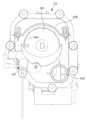
도 6은 도 1 및 도 4에 도시된 필터장치의 내부를 도시한다. 도 7은 도 6에 도시된 필터장치를 분해하여 도시한다. 도 8은 도 7에 도시된 필터장치를 도 7과 상이한 방향에서 도시한다. 도 9는 도 6에 도시된 필터장치의 일부 구성의 단면을 도시한다.Fig. 6 illustrates the interior of the filter device illustrated in Figs. 1 and 4. Fig. 7 illustrates the filter device illustrated in Fig. 6 in an exploded manner. Fig. 8 illustrates the filter device illustrated in Fig. 7 from a different direction than Fig. 7. Fig. 9 illustrates a cross-section of a portion of the filter device illustrated in Fig. 6.
도 6 내지 도 8을 참조하면, 일 실시예에 따른 필터장치(100)는 각종 구성품을 수용하는 필터 하우징(101)을 포함할 수 있다. 필터 하우징(101)은 하우징 바디(102)와, 하우징 커버(103)와, 하우징 브라켓(104)을 포함할 수 있다. 일 예로, 하우징 바디(102)와, 하우징 커버(103)와, 하우징 브라켓(104)은 각각 별도의 구성으로 마련될 수 있다. 일 예로, 하우징 바디(102)는 하우징 커버(103)와 일체로 형성될 수 있다. 일 예로, 하우징 바디(102)는 하우징 브라켓(104)과 일체로 형성될 수 있다. 일 예로, 하우징 커버(103)는 하우징 브라켓(104)과 일체로 형성될 수 있다. 일 예로, 하우징 바디(102)는 하우징 커버(103) 및 하우징 브라켓(104)과 일체로 형성될 수 있다.Referring to FIGS. 6 to 8, a filter device (100) according to one embodiment may include a filter housing (101) that accommodates various components. The filter housing (101) may include a housing body (102), a housing cover (103), and a housing bracket (104). For example, the housing body (102), the housing cover (103), and the housing bracket (104) may each be provided as separate components. For example, the housing body (102) may be formed integrally with the housing cover (103). For example, the housing body (102) may be formed integrally with the housing bracket (104). For example, the housing cover (103) may be formed integrally with the housing bracket (104). For example, the housing body (102) may be formed integrally with the housing cover (103) and the housing bracket (104).
하우징 바디(102)는 각종 구성품을 수용하기 위한 공간을 형성할 수 있다. 하우징 바디(102)는 내부에 수용되는 필터(120)가 연장되는 방향에 수직한 단면이 대략 U 형상을 가질 수 있다. 하우징 바디(102)는 전면과, 후면과, 상면이 개방된 박스 형상을 가질 수 있다. 하우징 바디(102)는 하우징 커버(103) 및/또는 하우징 브라켓(104)에 분리 가능하게 결합될 수 있다.The housing body (102) can form a space for accommodating various components. The housing body (102) can have a cross-section that is approximately U-shaped and is perpendicular to the direction in which the filter (120) accommodated inside extends. The housing body (102) can have a box shape with the front, back, and top surfaces open. The housing body (102) can be detachably coupled to the housing cover (103) and/or the housing bracket (104).
하우징 바디(102)는 필터장치(100)의 내부로 물이 유입되기 위한 하우징 유입부(102a)와, 필터장치(100)의 내부의 물을 필터장치(100)의 외부로 배출하기 위한 하우징 배출부(102b)를 포함할 수 있다. 하우징 유입부(102a) 및/또는 하우징 배출부(102b)는 하우징 바디(102)의 하부에 위치할 수 있다.The housing body (102) may include a housing inlet (102a) for allowing water to flow into the interior of the filter device (100), and a housing discharge (102b) for discharging water inside the filter device (100) to the exterior of the filter device (100). The housing inlet (102a) and/or the housing discharge (102b) may be located at the lower portion of the housing body (102).
하우징 유입부(102a)는 세탁기(10, 10a)의 배수호스(74, 74a)와 연결될 수 있다. 하우징 배출부(102b)는 배수라인(105)과 연결될 수 있다.The housing inlet (102a) can be connected to the drain hose (74, 74a) of the washing machine (10, 10a). The housing outlet (102b) can be connected to the drain line (105).
하우징 커버(103)는 하우징 바디(102)의 개방된 전면과 상면을 커버하도록 마련될 수 있다. 하우징 커버(103)는 하우징 바디(102) 및/또는 하우징 브라켓(104)에 분리 가능하게 결합될 수 있다. 하우징 커버(103)는 필터(120)가 통과 가능하도록 형성되는 커버 개구(103a)를 포함할 수 있다. 하우징 커버(103)는 사용자 인터페이스 장치(197,198; 200)가 설치되는 설치부(103b)를 포함할 수 있다. 사용자 인터페이스 장치(197,198; 200)는 적어도 일 부분이 설치부(103b)를 통해 필터장치(100)의 외부로 노출될 수 있다.The housing cover (103) may be provided to cover the open front and upper surface of the housing body (102). The housing cover (103) may be detachably coupled to the housing body (102) and/or the housing bracket (104). The housing cover (103) may include a cover opening (103a) formed to allow a filter (120) to pass through. The housing cover (103) may include an installation portion (103b) on which a user interface device (197, 198; 200) is installed. At least a portion of the user interface device (197, 198; 200) may be exposed to the outside of the filter device (100) through the installation portion (103b).
하우징 브라켓(104)은 하우징 바디(102)의 개방된 후면을 커버하도록 마련될 수 있다. 하우징 브라켓(104)은 하우징 바디(102) 및/또는 하우징 커버(103)에 분리 가능하게 결합될 수 있다. 하우징 브라켓(104)은 파워 케이블(109)이 통과 가능하도록 형성되는 케이블 개구(104a)를 포함할 수 있다. 하우징 브라켓(104)은 세탁기(10) 등을 포함한 외부장치와의 통신을 위한 커넥터(108)가 연결 가능하도록 형성되는 커넥터 장착부(104b)를 포함할 수 있다.The housing bracket (104) may be provided to cover the open rear surface of the housing body (102). The housing bracket (104) may be detachably coupled to the housing body (102) and/or the housing cover (103). The housing bracket (104) may include a cable opening (104a) formed to allow a power cable (109) to pass through. The housing bracket (104) may include a connector mounting portion (104b) formed to allow a connector (108) for communication with an external device, such as a washing machine (10), to be connected.
필터장치(100)는 필터 하우징(101)의 내부에 위치하는 필터 케이스(110)를 포함할 수 있다. 필터 케이스(110)는 필터장치(100)로 유입되는 물이 통과하는 유로를 형성할 수 있다. 필터 케이스(110)는 필터(120)를 수용 가능하도록 마련될 수 있다. 필터 케이스(110)는 케이스 바디(111)와, 케이스 커버(112)를 포함할 수 있다.The filter device (100) may include a filter case (110) positioned inside a filter housing (101). The filter case (110) may form a passage through which water flowing into the filter device (100) passes. The filter case (110) may be provided to accommodate a filter (120). The filter case (110) may include a case body (111) and a case cover (112).
케이스 바디(111)는 내부에 수용되는 필터(120)가 연장되는 방향을 따라 연장될 수 있다. 케이스 바디(111)는 필터(120)가 통과 가능하도록 형성되는 케이스 개구(111a)를 포함할 수 있다. 케이스 개구(111a)는 커버 개구(103a)에 대응되도록 마련될 수 있다. 케이스 개구(111a)는 케이스 유입부(112a)보다 케이스 배출부(111b)에 가깝게 위치하며, 필터(120)가 통과 가능하도록 마련될 수 있다.The case body (111) may extend along the direction in which the filter (120) accommodated therein extends. The case body (111) may include a case opening (111a) formed to allow the filter (120) to pass through. The case opening (111a) may be provided to correspond to the cover opening (103a). The case opening (111a) may be positioned closer to the case outlet (111b) than to the case inlet (112a), and may be provided to allow the filter (120) to pass through.
케이스 바디(111)는 필터 케이스(110)로 유입되는 물을 필터 케이스(110)로부터 배출하기 위한 케이스 배출부(111b)를 포함할 수 있다. 케이스 배출부(111b)는 케이스 바디(111)의 하부에 위치할 수 있다. 케이스 배출부(111b)는 케이스 개구(111a)에 인접하게 위치할 수 있다. 케이스 배출부(111b)는 필터(120)의 필터 개구(120a)가 위치하는 일 단과 반대되는 타 단에 가깝게 위치할 수 있다. 케이스 배출부(111b)는 필터(120)의 제1 필터부(121)보다 제2 필터부(122)에 가깝게 위치할 수 있다.The case body (111) may include a case discharge portion (111b) for discharging water flowing into the filter case (110) from the filter case (110). The case discharge portion (111b) may be located at the lower portion of the case body (111). The case discharge portion (111b) may be located adjacent to the case opening (111a). The case discharge portion (111b) may be located close to the other end opposite to the end where the filter opening (120a) of the filter (120) is located. The case discharge portion (111b) may be located closer to the second filter portion (122) than to the first filter portion (121) of the filter (120).
케이스 배출부(111b)는 하우징 배출부(102b)와 연결될 수 있다. 필터장치(100)는 케이스 배출부(111b)와 하우징 배출부(102b)를 연결하기 위한 배출 가이드(107)를 포함할 수 있다.The case discharge portion (111b) can be connected to the housing discharge portion (102b). The filter device (100) can include a discharge guide (107) for connecting the case discharge portion (111b) and the housing discharge portion (102b).
케이스 커버(112)는 케이스 바디(111)의 케이스 개구(111a)가 위치하는 일 단과 반대되는 타 단에 분리 가능하게 결합될 수 있다. 일 예로, 케이스 커버(112)는 케이스 바디(111)와 일체로 형성될 수도 있다.The case cover (112) can be detachably connected to one end of the case body (111) opposite to the end where the case opening (111a) of the case body (111) is located. For example, the case cover (112) can be formed integrally with the case body (111).
케이스 커버(112)는 필터 케이스(110)의 내부로 물이 유입되기 위한 케이스 유입부(112a)를 포함할 수 있다. 케이스 유입부(112a)는 하우징 유입부(102a)와 연결될 수 있다. 필터장치(100)는 케이스 유입부(112a)와 하우징 유입부(102a)를 연결하기 위한 유입 가이드(106)를 포함할 수 있다. 케이스 유입부(112a)는 유입구를 포함할 수 있다.The case cover (112) may include a case inlet (112a) for allowing water to flow into the interior of the filter case (110). The case inlet (112a) may be connected to the housing inlet (102a). The filter device (100) may include an inlet guide (106) for connecting the case inlet (112a) and the housing inlet (102a). The case inlet (112a) may include an inlet port.
케이스 커버(112)는 필터 청소장치(130)를 장착하기 위한 모터 장착부(112b)를 포함할 수 있다.The case cover (112) may include a motor mounting portion (112b) for mounting a filter cleaning device (130).
케이스 커버(112)는 필터의 막힘을 감지하는 필터센서(181)를 더 포함할 수 있다. 필터센서(181)의 구체적인 구성에 대해서는 도 13에 도시된다.The case cover (112) may further include a filter sensor (181) that detects clogging of the filter. The specific configuration of the filter sensor (181) is illustrated in FIG. 13.
청소모터(136)에는 자성체 구조물(183)이 부착될 수 있다.A magnetic structure (183) can be attached to the cleaning motor (136).
자성체 구조물(183)은 모터와 결합되는 자성체(183a)를 포함할 수 있다. 자성체(183a)는 자성체 구조물(183)은 청소 모터(136)의 회전에 따라 회전할 수 있다.The magnetic structure (183) may include a magnetic body (183a) coupled with a motor. The magnetic body (183a) may rotate according to the rotation of the cleaning motor (136).
결과적으로, 자성체(183a)는 청소 모터(136)의 회전에 따라 회전할 수 있다.As a result, the magnet (183a) can rotate according to the rotation of the cleaning motor (136).
필터센서(181)는 홀 센서, 리미트 스위치, 가속도계를 포함할 수 있다. 필터센서(181)는 자성체 구조물(183)보다 하단에 위치할 수 있다. 모터 장착부(112b)는 케이스 유입부(112a)보다 상측에 위치할 수 있다. 모터 장착부(112b)에는 필터 청소장치(130)의 청소모터(136)가 장착될 수 있다.The filter sensor (181) may include a hall sensor, a limit switch, and an accelerometer. The filter sensor (181) may be located below the magnetic structure (183). The motor mounting portion (112b) may be located above the case inlet portion (112a). A cleaning motor (136) of a filter cleaning device (130) may be mounted on the motor mounting portion (112b).
필터장치(100)는 필터 케이스(110)에 분리 가능하게 결합 가능한 필터(120)를 포함할 수 있다. 필터(120)는 미세한 크기의 이물질을 여과 가능하도록 마련될 수 있다. 필터(120)는 크기가 대략 5mm 이하인 미세플라스틱을 여과할 수 있도록 마련될 수 있다. 필터(120)는 메쉬 필터를 포함할 수 있다. 필터(120)는 대략 케이스 유입부(112a)와 케이스 배출부(111b) 사이에서 연장될 수 있다.The filter device (100) may include a filter (120) that is detachably connectable to a filter case (110). The filter (120) may be provided to filter foreign substances of a fine size. The filter (120) may be provided to filter microplastics having a size of approximately 5 mm or less. The filter (120) may include a mesh filter. The filter (120) may extend approximately between a case inlet (112a) and a case outlet (111b).
필터(120)는 필터 케이스(110)에 장착된 때, 케이스 유입부(112a)를 향해 개방되는 필터 개구(120a)를 포함할 수 있다. 케이스 유입부(112a)를 통해 필터 케이스(110)로 유입되는 물은 필터 개구(120a)를 통해 필터(120)의 내부로 이동할 수 있다.The filter (120) may include a filter opening (120a) that opens toward the case inlet (112a) when mounted in the filter case (110). Water flowing into the filter case (110) through the case inlet (112a) may move into the interior of the filter (120) through the filter opening (120a).
필터(120)는 제1 필터부(121) 및 제2 필터부(122)를 포함할 수 있다. 제1 필터부(121)는 제2 필터부(122)보다 케이스 유입부(112a)에 가깝게 위치할 수 있다. 필터 케이스(110)로 유입되는 물은 제1 필터부(121)에서 이물질이 여과되거나, 제1 필터부(121)에서 이물질이 여과되지 않고 제1 필터부(121)를 통과한 후 제2 필터부(122)에서 이물질이 여과될 수 있다. 제1 필터부(121)와 제2 필터부(122)는 필터(120)가 연장되는 방향을 따라 순차적으로 배치될 수 있다. 제2 필터부(122)에는 필터 청소장치(130)에 의해 제1 필터부(121)로부터 이송되는 이물질이 수집될 수 있다.The filter (120) may include a first filter unit (121) and a second filter unit (122). The first filter unit (121) may be positioned closer to the case inlet (112a) than the second filter unit (122). Water flowing into the filter case (110) may have foreign substances filtered out by the first filter unit (121), or may pass through the first filter unit (121) without being filtered out by the first filter unit (121) and then be filtered out by the second filter unit (122). The first filter unit (121) and the second filter unit (122) may be sequentially arranged along the direction in which the filter (120) extends. Foreign substances transferred from the first filter unit (121) by the filter cleaning device (130) may be collected in the second filter unit (122).
필터장치(100)는 필터(120)가 필터 케이스(110)에 장착된 때, 필터 하우징(101)의 외부로 적어도 일 부분이 노출되는 핸들(129)을 포함할 수 있다. 핸들(129)은 필터(120)에 분리 가능하게 결합될 수 있다. 핸들(129)이 필터(120)에 분리 가능하게 결합됨에 따라, 필터(120)는 유지 및/또는 보수가 용이해질 수 있다. 핸들(129)은 커버 개구(103a) 및/또는 케이스 개구(111a)에 회전하며 결합될 수 있다.The filter device (100) may include a handle (129) at least a portion of which is exposed to the outside of the filter housing (101) when the filter (120) is mounted in the filter case (110). The handle (129) may be detachably coupled to the filter (120). As the handle (129) is detachably coupled to the filter (120), the filter (120) may be easily maintained and/or repaired. The handle (129) may be rotatably coupled to the cover opening (103a) and/or the case opening (111a).
필터장치(100)는 필터(120)를 청소하기 위한 필터 청소장치(130)를 포함할 수 있다. 필터 청소장치(130)는 필터 케이스(110)에 장착될 수 있다. 필터 청소장치(130)는 필터(120)의 이물질이 여과되는 면을 청소하기 위한 청소부재(131)와, 청소부재(131)를 구동시키기 위한 청소 구동장치(135)를 포함할 수 있다.The filter device (100) may include a filter cleaning device (130) for cleaning the filter (120). The filter cleaning device (130) may be mounted on the filter case (110). The filter cleaning device (130) may include a cleaning member (131) for cleaning the surface of the filter (120) through which foreign substances are filtered, and a cleaning driving device (135) for driving the cleaning member (131).
청소부재(131)는 필터(120)의 내부에 위치할 수 있다. 청소부재(131)는 필터(120)의 제1 필터부(121)에 대응되도록 마련될 수 있다. 청소부재(131)는 나선형으로 연장되는 블레이드(131a)를 가질 수 있다. 블레이드(131a)는 청소부재(131)의 회전 축으로부터 반경 방향으로 연장될 수 있다. 청소부재(131)는 필터(120)의 이물질이 여과되는 면에 접촉하도록 마련될 수 있다. 청소부재(131)는 필터(120)의 내측면에 접촉하도록 마련될 수 있다. 일 예로, 청소부재(131)는 복수의 브러쉬를 포함할 수도 있다.The cleaning member (131) may be positioned inside the filter (120). The cleaning member (131) may be provided to correspond to the first filter portion (121) of the filter (120). The cleaning member (131) may have a blade (131a) extending in a spiral shape. The blade (131a) may extend radially from the rotational axis of the cleaning member (131). The cleaning member (131) may be provided to contact a surface of the filter (120) on which foreign substances are filtered. The cleaning member (131) may be provided to contact an inner surface of the filter (120). For example, the cleaning member (131) may include a plurality of brushes.
청소부재(131)는 청소 구동장치(135)에 의해 구동되는 동안, 케이스 유입부(112a)에 가까운 필터(120)의 일 부분에서 여과되는 이물질을 필터(120)의 케이스 배출부(111b)에 가까운 필터(120)의 일 부분으로 이송시키도록 마련될 수 있다. 청소부재(131)는 제1 필터부(121)에 여과된 이물질을 제2 필터부(122)로 이송시키도록 마련될 수 있다. 일 예로, 청소부재(131)는 필터(120)의 내부에 회전 가능하게 마련될 수 있다. 청소부재(131)는 유연한 재질의 재료를 포함할 수 있다. 청소부재(131)는 필터(120)에 접촉된 상태로 회전하며 필터(120)에서 여과된 이물질을 청소할 수 있다. 청소부재(131)는 필터(120)에 접촉된 상태로 구동되는 동안, 필터(120)의 이물질이 여과되는 면에 붙어있는 이물질을 긁으며 제거할 수 있다. 일 예로, 청소부재(131)는 필터(120)의 내부에 슬라이딩 가능하게 마련될 수 있다.The cleaning member (131) may be provided to transfer foreign substances filtered in a portion of the filter (120) close to the case inlet (112a) to a portion of the filter (120) close to the case discharge portion (111b) of the filter (120) while being driven by the cleaning driving device (135). The cleaning member (131) may be provided to transfer foreign substances filtered in the first filter portion (121) to the second filter portion (122). For example, the cleaning member (131) may be provided to be rotatably located inside the filter (120). The cleaning member (131) may include a flexible material. The cleaning member (131) may rotate while in contact with the filter (120) and clean foreign substances filtered in the filter (120). The cleaning member (131) can scrape and remove foreign substances attached to the filter surface of the filter (120) while being driven in contact with the filter (120). For example, the cleaning member (131) can be provided so as to be slidable within the filter (120).
청소부재(131)가 제1 필터부(121)에 여과된 이물질을 제2 필터부(122)로 이송시키도록 마련되며, 필터 케이스(110)로 유입되는 물이 제1 필터부(121)로부터 제2 필터부(122)로 흐름에 따라, 제1 필터부(121)에 여과된 이물질은 제2 필터부(122)에 효율적으로 수집될 수 있다.The cleaning member (131) is provided to transfer foreign substances filtered in the first filter unit (121) to the second filter unit (122), and as water flowing into the filter case (110) flows from the first filter unit (121) to the second filter unit (122), foreign substances filtered in the first filter unit (121) can be efficiently collected in the second filter unit (122).
청소 구동장치(135)는 청소모터(136)와 모터 축(137)을 포함할 수 있다. 청소모터(136)는 청소부재(131)를 구동시키기 위한 동력을 생성하도록 구성될 수 있다. 모터 축(137)은 청소부재(131)와 연결될 수 있다. 청소모터(136)는 필터 케이스(110)에 장착될 수 있다. 청소모터(136)는 케이스 배출부(112b)보다 케이스 유입부(112a)에 가깝게 위치할 수 있다.The cleaning drive device (135) may include a cleaning motor (136) and a motor shaft (137). The cleaning motor (136) may be configured to generate power for driving the cleaning member (131). The motor shaft (137) may be connected to the cleaning member (131). The cleaning motor (136) may be mounted on the filter case (110). The cleaning motor (136) may be located closer to the case inlet (112a) than to the case discharge portion (112b).
필터장치(100)는 필터 하우징(101)의 내부에 위치하는 전장부 모듈(190, circuitry module)를 포함할 수 있다. 전장부 모듈(190)은 필터 하우징(101)의 내부의 상단부에 위치할 수 있다. 전장부 모듈(190)은 필터 케이스(110)의 일 측에 위치할 수 있다. 일 예로, 전장부 모듈(190)은 필터 케이스(110)의 상측에 위치할 수 있다. 일 예로, 전장부 모듈(190)은 필터(120)의 상측에 배치될 수 있다.The filter device (100) may include a circuitry module (190) positioned inside the filter housing (101). The circuitry module (190) may be positioned at an upper portion of the inside of the filter housing (101). The circuitry module (190) may be positioned on one side of the filter case (110). For example, the circuitry module (190) may be positioned on the upper side of the filter case (110). For example, the circuitry module (190) may be arranged on the upper side of the filter (120).
또 다른 예로, 전장부 모듈(190)은 필터 케이스(110)의 하측, 좌측, 우측, 전방측 및/또는 후측에 마련될 수 있다.As another example, the front module (190) may be provided on the lower side, left side, right side, front side and/or rear side of the filter case (110).
전장부 모듈(190)에는 필터장치(100)를 제어하기 위한 제어부(191)와, 세탁기(10, 10a)와 통신하기 위한 통신부(199)가 마련될 수 있다.The main body module (190) may be provided with a control unit (191) for controlling the filter device (100) and a communication unit (199) for communicating with the washing machine (10, 10a).
필터장치(100)는 전장부 모듈(190)의 상측에 위치하는 사용자 인터페이스 장치(197, 198; 200)를 포함할 수 있다. 사용자 인터페이스 장치(197, 198; 200)는 적어도 일 부분이 필터 하우징(101)의 설치부(103b)를 통해 필터장치(100)의 외부로 노출될 수 있다. 사용자 인터페이스 장치(197, 198; 200)는 필터장치(100)의 상면에 위치할 수 있다. 사용자 인터페이스 장치(197, 198; 200)는 적어도 하나의 입력 인터페이스(197)와, 적어도 하나의 출력 인터페이스(198)를 포함할 수 있다. 출력 인터페이스(198)는 디스플레이를 포함할 수 있다. 다양한 실시예에 따라, 사용자 인터페이스 장치(197, 198; 200)는 필터 하우징(101)의 상측, 하측, 좌측, 우측, 전방측 및/또는 후측에 마련될 수 있다.The filter device (100) may include a user interface device (197, 198; 200) positioned on the upper side of the front module (190). At least a portion of the user interface device (197, 198; 200) may be exposed to the outside of the filter device (100) through the installation portion (103b) of the filter housing (101). The user interface device (197, 198; 200) may be positioned on the upper surface of the filter device (100). The user interface device (197, 198; 200) may include at least one input interface (197) and at least one output interface (198). The output interface (198) may include a display. According to various embodiments, the user interface device (197, 198; 200) may be provided on the upper side, lower side, left side, right side, front side and/or rear side of the filter housing (101).
적어도 하나의 입력 인터페이스(197)는 사용자로부터 수신된 감각 정보(sensory information)를 전기적인 신호로 전환할 수 있다.At least one input interface (197) can convert sensory information received from a user into an electrical signal.
적어도 하나의 입력 인터페이스(197)는 전원 버튼, 동작 버튼 및/또는 통신 버튼을 포함할 수 있다. 적어도 하나의 입력 인터페이스(197)는, 예를 들어, 택트 스위치(tact switch), 푸시 스위치, 슬라이드 스위치, 토클 스위치, 마이크로 스위치, 터치 스위치, 터치 패드, 터치 스크린, 조그 다이얼, 및/또는 마이크로폰 등을 포함할 수 있다.At least one input interface (197) may include a power button, an action button, and/or a communication button. The at least one input interface (197) may include, for example, a tact switch, a push switch, a slide switch, a toggle switch, a micro switch, a touch switch, a touch pad, a touch screen, a jog dial, and/or a microphone.
다양한 실시예에 따라, 전원 버튼은 필터장치(100)에 전원을 공급하기 위한 버튼이고, 동작 버튼은 필터 청소장치(130)를 동작시키기 위한 버튼이고, 통신 버튼은 필터장치(100)를 외부장치(예: 세탁기, 사용자 기기, 가전기기 등)와 통신 가능한 상태로 전환하기 위한 버튼일 수 있다.According to various embodiments, the power button may be a button for supplying power to the filter device (100), the operation button may be a button for operating the filter cleaning device (130), and the communication button may be a button for switching the filter device (100) to a state where it can communicate with an external device (e.g., a washing machine, a user device, a home appliance, etc.).
적어도 하나의 출력 인터페이스(198)는 감각 정보를 생성함으로써 사용자에게 필터장치(100)의 동작 및/또는 상태에 관련된 다양한 정보를 전달할 수 있다.At least one output interface (198) can transmit various information related to the operation and/or status of the filter device (100) to the user by generating sensory information.
예를 들어, 적어도 하나의 출력 인터페이스(198)는 필터장치(100)로의 물의 유입 상태, 필터(120)의 막힘 상태, 필터장치(100)에 마련된 적어도 하나의 센서의 상태, 필터 청소장치(130)의 동작 상태에 관련된 정보를 사용자에게 전달할 수 있다.For example, at least one output interface (198) can transmit information related to the state of water inflow into the filter device (100), the state of blockage of the filter (120), the state of at least one sensor provided in the filter device (100), and the operating state of the filter cleaning device (130) to the user.
필터장치(100)의 동작 및/또는 상태에 관련된 다양한 정보는 스크린, 인디케이터, 음성 등으로 출력될 수 있다. 적어도 하나의 출력 인터페이스(198)는, 예를 들어, 액정 디스플레이(Liquid Crystal Display, LCD) 패널, 발광 다이오드(Light Emitting Diode, LED) 패널, 발광 다이오드(Light Emitting Diode, LED) 모듈, 스피커 등을 포함할 수 있다.Various information related to the operation and/or status of the filter device (100) may be output via a screen, indicator, voice, etc. At least one output interface (198) may include, for example, a liquid crystal display (LCD) panel, a light emitting diode (LED) panel, a light emitting diode (LED) module, a speaker, etc.
출력 인터페이스(198)는 필터장치(100)의 상면에 위치할 수 있다. 다만, 출력 인터페이스(198)의 위치가 이에 한정되는 것은 아니며, 출력 인터페이스(198)는 필터장치(100)의 전면, 측면 또는 후면에도 마련될 수 있다.The output interface (198) may be located on the upper surface of the filter device (100). However, the location of the output interface (198) is not limited thereto, and the output interface (198) may also be provided on the front, side, or rear of the filter device (100).
다양한 실시예에 따라, 적어도 하나의 입력 인터페이스(197)와 출력 인터페이스(198)는 필터 하우징(101)의 서로 다른 측의 면에 마련될 수 있다. 예를 들어, 적어도 하나의 입력 인터페이스(197)는 필터 하우징(101)의 상면에 마련되고 출력 인터페이스(198)는 필터 하우징(101)의 전면에 마련될 수도 있다.According to various embodiments, at least one input interface (197) and an output interface (198) may be provided on different sides of the filter housing (101). For example, at least one input interface (197) may be provided on an upper surface of the filter housing (101) and the output interface (198) may be provided on a front surface of the filter housing (101).
본 개시에 따르면, 사용자가 필터장치(100)에 다가갈 필요 없이 필터장치(100)의 전방에서 출력 인터페이스(198)를 통해 필터장치(100)의 동작 및/또는 상태에 관련된 다양한 정보를 확인할 수 있다. 또한, 본 개시에 따르면, 필터장치(100)의 상측에 마련된 적어도 하나의 입력 인터페이스(197)를 통해 자세를 낮출 필요 없이 용이하게 각종 명령을 입력할 수 있다.According to the present disclosure, a user can check various information related to the operation and/or status of the filter device (100) through an output interface (198) in front of the filter device (100) without having to approach the filter device (100). In addition, according to the present disclosure, various commands can be easily input without having to lower one's posture through at least one input interface (197) provided on the upper side of the filter device (100).
필터장치(100)는 필터(120)의 상태에 관한 정보를 획득하는 필터센서(181)를 포함할 수 있다. 필터센서(181)는 필터 케이스(110)에 장착될 수 있다. 필터센서(181; 도 13 참조)는 필터 케이스(110)의 외측에 위치할 수 있다. 필터센서(181)는 케이스 커버(112) 후면 하단에 위치할 수 있다.The filter device (100) may include a filter sensor (181) that obtains information about the state of the filter (120). The filter sensor (181) may be mounted on the filter case (110). The filter sensor (181; see FIG. 13) may be located on the outside of the filter case (110). The filter sensor (181) may be located at the lower rear side of the case cover (112).
필터센서(181)는 필터(120)의 막힘과 관련된 데이터를 획득할 수 있다. 예를 들어, 필터센서(181)는 모터의 회전에 따라 회전하는 자성체(183a)가 소정의 위치에 도달한 것을 감지할 수 있다. 필터센서(181)의 구체적인 구성은 도 13에 도시된다.The filter sensor (181) can obtain data related to the clogging of the filter (120). For example, the filter sensor (181) can detect that a magnetic body (183a) that rotates according to the rotation of the motor has reached a predetermined position. The specific configuration of the filter sensor (181) is illustrated in Fig. 13.
필터장치(100)는 필터장치(100)로 물이 유입되는 것을 감지하기 위한 급수센서(182)를 포함할 수 있다. 급수센서(182)는 케이스 유입부(112a)를 통한 물의 유입을 감지할 수 있다.The filter device (100) may include a water supply sensor (182) for detecting the inflow of water into the filter device (100). The water supply sensor (182) may detect the inflow of water through the case inlet (112a).
급수센서(182)는 필터 케이스(110)의 하부에 장착될 수 있다. 급수센서(182)는 필터 케이스(110)의 케이스 유입부(112a)에 가깝게 위치할 수 있다. 다양한 실시예에 따라, 급수센서(182)는 케이스 유입부(112a)의 내측에 마련될 수도 있다. 일 예로, 급수센서(182)는 정전용량센서 및/또는 유량센서를 포함할 수 있다.The water supply sensor (182) may be mounted on the lower part of the filter case (110). The water supply sensor (182) may be located close to the case inlet (112a) of the filter case (110). According to various embodiments, the water supply sensor (182) may be provided on the inside of the case inlet (112a). As an example, the water supply sensor (182) may include a capacitance sensor and/or a flow rate sensor.
도 9를 참조하면, 필터 케이스(110)는 필터 케이스(110)의 내부의 잔수를 가이드하도록 형성되는 잔수 가이드(119)를 포함할 수 있다. 잔수 가이드(119)는 중력 방향으로 필터(120)의 아래에 위치할 수 있다. 일 예로, 잔수 가이드(119)는 케이스 배출부(111b)로부터 케이스 유입부(112a)를 향해 갈수록 하향 경사지게 형성될 수 있다. 잔수 가이드(119)는 중력 방향에 수직한 방향에 대하여 소정 각도(a)를 가지도록 경사지게 형성될 수 있다. 잔수 가이드(119)에 의해 필터 케이스(110)의 내부의 물이 케이스 배출부(111b)를 통해 필터장치(100)의 외부로 배출되는 것을 방지할 수 있다.Referring to FIG. 9, the filter case (110) may include a residual water guide (119) formed to guide residual water inside the filter case (110). The residual water guide (119) may be positioned below the filter (120) in the direction of gravity. For example, the residual water guide (119) may be formed to slope downward from the case discharge portion (111b) toward the case inlet portion (112a). The residual water guide (119) may be formed to slope at a predetermined angle (a) with respect to a direction perpendicular to the direction of gravity. The residual water guide (119) may prevent water inside the filter case (110) from being discharged to the outside of the filter device (100) through the case discharge portion (111b).
케이스 배출부(111b)의 입구의 중력 방향에 따른 하단의 위치는 케이스 유입부(112a)의 중력 방향에 따른 하단의 위치보다 높게 형성될 수 있다. 필터 케이스(110)의 내부에 잔수가 발생하는 경우, 잔수는 중력에 의해 케이스 배출부(111b)의 주변으로부터 케이스 유입부(112a)를 향해 이동할 수 있다. 일 예로, 케이스 배출부(111b)의 입구와 케이스 유입부(112a) 사이의 필터 케이스(110)의 바닥면은 단차를 갖는 부분을 포함하도록 마련될 수 있다.The lower position of the case discharge port (111b) in the direction of gravity may be formed higher than the lower position of the case inlet port (112a) in the direction of gravity. When residual water is generated inside the filter case (110), the residual water may move from the periphery of the case discharge port (111b) toward the case inlet port (112a) by gravity. For example, the bottom surface of the filter case (110) between the inlet of the case discharge port (111b) and the case inlet port (112a) may be provided to include a portion having a step.
케이스 유입부(112a)는 필터(120)보다 아래에 위치할 수 있다. 케이스 유입부(112a)의 중력 방향에 따른 최상단은 필터(120)의 중력 방향에 따른 최상단보다 아래에 위치할 수 있다. 케이스 유입부(112a)의 중력 방향에 따른 최하단은 필터(120)의 중력 방향에 따른 최하단보다 아래에 위치할 수 있다. 케이스 배출부(111b)의 입구는 필터(120)보다 아래에 위치할 수 있다.The case inlet (112a) may be positioned below the filter (120). The uppermost part of the case inlet (112a) in the direction of gravity may be positioned below the uppermost part of the filter (120) in the direction of gravity. The lowermost part of the case inlet (112a) in the direction of gravity may be positioned below the lowermost part of the filter (120) in the direction of gravity. The inlet of the case discharge (111b) may be positioned below the filter (120).
필터 케이스(110)는 연결구(118)를 포함할 수 있다. 연결구(118)는 잔수 가이드(119)의 케이스 유입부(112a)에 가까운 일 단에 위치할 수 있다. 연결구(118)는 잔수 가이드(119)에 의해 가이드되는 물을 케이스 유입부(112a)를 향해 배출할 수 있도록 필터 케이스(110)에 형성될 수 있다.The filter case (110) may include a connection port (118). The connection port (118) may be located at one end close to the case inlet (112a) of the residual water guide (119). The connection port (118) may be formed in the filter case (110) so as to discharge water guided by the residual water guide (119) toward the case inlet (112a).
필터장치(100)는 연결구(118)를 개폐하기 위한 개폐장치(140)를 포함할 수 있다. 개폐장치(140)는 연결 도어(141)와, 연결 도어(141)를 작동시키기 위한 도어 모터(142)를 포함할 수 있다.The filter device (100) may include an opening/closing device (140) for opening/closing the connection port (118). The opening/closing device (140) may include a connection door (141) and a door motor (142) for operating the connection door (141).
연결 도어(141)는 연결구(118)를 개폐하도록 마련될 수 있다. 연결 도어(141)는 연결구(118)를 폐쇄할 수 있는 크기 및/또는 모양으로 마련될 수 있다. 연결 도어(141)는 필터 케이스(110)에 회전 가능하게 결합될 수 있다. 연결 도어(141)는 잔수 가이드(119)로부터 케이스 유입부(112a)로 물이 흐르는 방향으로 회전 가능하게 마련될 수 있다. 연결 도어(141)는 케이스 유입부(112a)를 통해 유입되는 물이 연결구(118)로 유입되는 방향과 반대 방향으로 회전 가능하게 마련될 수 있다. 연결 도어(141)는 케이스 유입부(112a)를 통해 유입되는 물의 수압에 의해 연결구(118)를 개방하는 것이 방지되도록 마련될 수 있다.The connecting door (141) may be provided to open and close the connecting port (118). The connecting door (141) may be provided in a size and/or shape that can close the connecting port (118). The connecting door (141) may be rotatably coupled to the filter case (110). The connecting door (141) may be provided to be rotatably in the direction in which water flows from the residual water guide (119) to the case inlet (112a). The connecting door (141) may be provided to be rotatably in the opposite direction to the direction in which water flowing in through the case inlet (112a) flows into the connecting port (118). The connecting door (141) may be provided to prevent the connecting port (118) from being opened by the water pressure of the water flowing in through the case inlet (112a).
도어 모터(142)는 연결 도어(141)를 작동시키기 위한 동력을 생성하도록 마련될 수 있다. 개폐장치(140)는 도어 모터(142)에서 발생되는 동력을 연결 도어(141)로 전달하기 위한 동력 전달장치(143)를 포함할 수 있다. 도어 모터(142)에서 발생되는 동력은 동력 전달장치를 통해 연결 도어(141)로 전달될 수 있다.The door motor (142) may be provided to generate power for operating the connecting door (141). The opening/closing device (140) may include a power transmission device (143) for transmitting power generated from the door motor (142) to the connecting door (141). Power generated from the door motor (142) may be transmitted to the connecting door (141) through the power transmission device.
필터 케이스(110)의 내부에는 필터(120)를 통과하는 필터링 유로(116)와, 필터(120)를 우회하는 우회 유로(117)가 형성될 수 있다. 케이스 유입부(112a)를 통해 유입되는 물은 필터링 유로(116)를 통해 케이스 배출부(111b)로 이동하거나, 우회 유로(117)를 통해 케이스 배출부(111b)로 이동할 수 있다.Inside the filter case (110), a filtering path (116) passing through the filter (120) and a bypass path (117) bypassing the filter (120) may be formed. Water flowing in through the case inlet (112a) may move to the case outlet (111b) through the filtering path (116) or to the case outlet (111b) through the bypass path (117).
연결구(118)는 우회 유로(117)의 케이스 유입부(112a)에 가까운 일 단에 위치할 수 있다. 연결 도어(141)가 연결구(118)를 개방하는 동안, 케이스 유입부(112a)를 통해 유입되는 물은 필터링 유로(116)를 거치지 않고 우회 유로(117)로 직접 이동할 수 있다. 연결 도어(141)가 연결구(118)를 개방하는 동안, 우회 유로(117)의 물은 필터링 유로(116)를 거치지 않고 케이스 유입부(112a)로 직접 이동할 수 있다. 연결구(118)는 우회 유로(117)의 물이 케이스 유입부(112a)로 이동 가능하거나, 케이스 유입부(112a)로 유입되는 물이 우회 유로(117)로 이동 가능하도록 형성될 수 있다.The connection port (118) may be located at one end close to the case inlet (112a) of the bypass passage (117). While the connection door (141) opens the connection port (118), water flowing in through the case inlet (112a) can move directly to the bypass passage (117) without passing through the filtering passage (116). While the connection door (141) opens the connection port (118), water in the bypass passage (117) can move directly to the case inlet (112a) without passing through the filtering passage (116). The connection port (118) may be formed so that water in the bypass passage (117) can move to the case inlet (112a), or so that water flowing into the case inlet (112a) can move to the bypass passage (117).
도 10은 도 9에 도시된 필터 케이스로 유입되는 물이 필터를 통과하는 경우 구조를 도시한다.Figure 10 illustrates the structure when water flowing into the filter case illustrated in Figure 9 passes through the filter.
도 10을 참조하면, 하우징 유입부(102a)를 통해 필터장치(100)로 유입되는 물은 유입 가이드(106)에 의해 필터 케이스(110)로 가이드될 수 있다. 케이스 유입부(112a)를 통해 필터 케이스(110)의 내부로 유입되는 물은 필터 개구(120a)를 통해 필터(120)의 내부로 유입될 수 있다. 필터 케이스(110)로 유입되는 물은 필터링 유로(116)로 흐를 수 있다. 연결 도어(141)가 연결구(118)를 닫고 있으므로, 필터 케이스(110)로 유입되는 물은 연결구(118)를 통해 우회 유로(117)로 흐를 수 없다. 필터(120)의 내부로 유입되는 물은 필터(120)를 통과하며 이물질이 여과될 수 있다. 필터(120)를 통과한 물은 케이스 배출부(111b)를 통해 필터 케이스(110)의 외부로 배출될 수 있다. 케이스 배출부(111b)를 통해 배출되는 물은 배출 가이드(107) 및 하우징 배출부(102b)를 순차적으로 통과하여 필터장치(100)로부터 배출될 수 있다. 필터장치(100)로부터 배출되는 물은 배수라인(105)을 통해 가이드될 수 있다.Referring to FIG. 10, water flowing into the filter device (100) through the housing inlet (102a) can be guided to the filter case (110) by the inlet guide (106). Water flowing into the interior of the filter case (110) through the case inlet (112a) can flow into the interior of the filter (120) through the filter opening (120a). Water flowing into the filter case (110) can flow into the filtering path (116). Since the connection door (141) closes the connection port (118), water flowing into the filter case (110) cannot flow into the bypass path (117) through the connection port (118). Water flowing into the interior of the filter (120) can pass through the filter (120) and foreign substances can be filtered. Water passing through the filter (120) can be discharged to the outside of the filter case (110) through the case discharge portion (111b). Water discharged through the case discharge portion (111b) can be discharged from the filter device (100) by sequentially passing through the discharge guide (107) and the housing discharge portion (102b). Water discharged from the filter device (100) can be guided through the drain line (105).
도 11은 도 10에 도시된 필터가 막힌 경우, 물의 흐름을 도시한다.Figure 11 illustrates the flow of water when the filter illustrated in Figure 10 is clogged.
도 11을 참조하면, 일 실시예에 따른 필터장치(100)의 필터(120)가 이물질에 의해 막힌 경우, 개폐장치(140)는 연결구(118)를 개방할 수 있다. 필터(120)가 이물질에 의해 막히는 경우, 개폐장치(140)는 우회 유로(117)를 개방할 수 있다. 연결 도어(141)는 연결구(118)를 개방하도록 회전할 수 있다. 연결 도어(141)는 우회 유로(117)를 개방하도록 회전할 수 있다.Referring to FIG. 11, when the filter (120) of the filter device (100) according to one embodiment is blocked by a foreign substance, the opening/closing device (140) can open the connection port (118). When the filter (120) is blocked by a foreign substance, the opening/closing device (140) can open the bypass passage (117). The connection door (141) can rotate to open the connection port (118). The connection door (141) can rotate to open the bypass passage (117).
우회 유로(117)가 개방됨에 따라, 필터 케이스(110)로 유입되는 물은 우회 유로(117)를 따라 이동할 수 있다. 필터 케이스(110)로 유입되는 물은 연결구(118)를 통해 우회 유로(117)의 내부로 유입된 후, 케이스 배출부(111b)를 통해 필터 케이스(110)의 외부로 배출될 수 있다.As the bypass passage (117) is opened, water flowing into the filter case (110) can move along the bypass passage (117). Water flowing into the filter case (110) can flow into the interior of the bypass passage (117) through the connection port (118) and then be discharged to the exterior of the filter case (110) through the case discharge port (111b).
이러한 구성에 따라, 다양한 실시예에 따른 의류 처리 장치(1)는 필터(120)의 일 부분이 막히게 되더라도, 필터장치(100)로부터 물을 배출할 수 있으며, 따라서, 필터장치(100)의 동작이 정지되는 것을 방지할 수 있다.According to this configuration, the clothing treatment device (1) according to various embodiments can discharge water from the filter device (100) even if a part of the filter (120) is blocked, and thus, can prevent the operation of the filter device (100) from stopping.
도 12는 일 실시예에 따른 자성체 및 필터센서의 구조를 도시한다.Fig. 12 illustrates the structure of a magnetic body and filter sensor according to one embodiment.
도 12를 참조하면, 자성체 구조물(183)은 자성체(183a)를 포함할 수 있다. 자성체 구조물(183)은 모터 축(137)에 의해 고정될 수 있다. 자성체 구조물(183)은 청소 모터(136)에 부착될 수 있다. 청소 모터(136)가 회전하면 자성체 구조물(183)은 회전할 수 있다. 자성체 구조물(183)이 회전함에 따라, 자성체(183a)도 회전할 수 있다.Referring to FIG. 12, the magnetic structure (183) may include a magnetic body (183a). The magnetic structure (183) may be fixed by a motor shaft (137). The magnetic structure (183) may be attached to a cleaning motor (136). When the cleaning motor (136) rotates, the magnetic structure (183) may rotate. As the magnetic structure (183) rotates, the magnetic body (183a) may also rotate.
도 13는 도 12에 도시된 자성체 및 필터센서를 상이한 방향에서 도시한다. 도 14는 도 12에 도시된 자성체 및 필터센서를 상이한 방향에서 도시한다. 도 13는 도 12에 도시된 자성체 및 필터센서를 상이한 방향에서 도시한다.Fig. 13 illustrates the magnet and filter sensor illustrated in Fig. 12 from different directions. Fig. 14 illustrates the magnet and filter sensor illustrated in Fig. 12 from different directions. Fig. 13 illustrates the magnet and filter sensor illustrated in Fig. 12 from different directions.
도 13 내지 도 14를 참조하면, 일 실시예에서, 필터센서(181)는 자성체 구조물(183)의 일 측에 위치할 수 있다. 예를 들어, 필터센서(181)는 자성체 구조물(183)의 하단에 위치할 수 있다.Referring to FIGS. 13 and 14, in one embodiment, the filter sensor (181) may be located on one side of the magnetic structure (183). For example, the filter sensor (181) may be located on the bottom of the magnetic structure (183).
자성체(183a)는 자성체 구조물(183)에 의해 고정될 수 있다. 자성체(183a)는 자성체 구조물(183)의 회전에 따라 동시에 회전할 수 있다. 필터센서(181)는 자성체(183a)의 회전을 감지할 수 있다.The magnetic body (183a) can be fixed by the magnetic body structure (183). The magnetic body (183a) can rotate simultaneously with the rotation of the magnetic body structure (183). The filter sensor (181) can detect the rotation of the magnetic body (183a).
예를 들어, 필터센서(181)는 자성체(183a)의 자기장을 감지할 수 있다. 필터센서(181)는 자성체(183a)가 소정의 위치에 도달하면 자성체(183a)의 자기장을 감지하여 HIGH 신호를 출력할 수 있다.For example, the filter sensor (181) can detect the magnetic field of the magnetic body (183a). When the magnetic body (183a) reaches a predetermined position, the filter sensor (181) can detect the magnetic field of the magnetic body (183a) and output a HIGH signal.
도 14는 도 12에 도시된 자성체 및 필터센서를 상이한 방향에서 도시한다. 자성체 구조물(183)은 원판 모양으로 형성될 수 있다. 자성체(183a)는 자성체 구조물(183)의 회전에 따라 동시에 회전할 수 있다. 필터센서(181)는 자성체(183a)의 회전을 감지할 수 있다.Fig. 14 illustrates the magnetic body and filter sensor illustrated in Fig. 12 from different directions. The magnetic body structure (183) may be formed in a disk shape. The magnetic body (183a) may rotate simultaneously with the rotation of the magnetic body structure (183). The filter sensor (181) may detect the rotation of the magnetic body (183a).
도 15는 일 실시예에 따른 필터장치의 구성들과 구성들 간의 신호 흐름을 간략하게 도시한다.FIG. 15 briefly illustrates the configurations of a filter device and the signal flow between the configurations according to one embodiment.
도 15를 참조하면, 일 실시예에 따른 필터장치(100)는 사용자와의 상호 작용을 위한 사용자 인터페이스 장치(197, 198; 200)와, 필터센서(181)와, 급수센서(182)와, 필터 청소장치(130)와, 개폐장치(140)와, 통신부(199)와, 필터장치(100)의 각종 구성을 제어하는 제어부(191)를 포함할 수 있다.Referring to FIG. 15, a filter device (100) according to one embodiment may include a user interface device (197, 198; 200) for interaction with a user, a filter sensor (181), a water supply sensor (182), a filter cleaning device (130), an opening/closing device (140), a communication unit (199), and a control unit (191) for controlling various components of the filter device (100).
제어부(191)는 전술한 동작 및 후술하는 동작을 수행하기 위해, 적어도 하나의 메모리(191a)와 적어도 하나의 프로세서(191b)를 포함할 수 있다.The control unit (191) may include at least one memory (191a) and at least one processor (191b) to perform the operations described above and the operations described below.
일 실시예에서, 제어부(191)는 필터장치(100) 내 구성요소들의 동작을 제어하기 위한 알고리즘 및/또는 프로그램 형태의 데이터를 저장하는 적어도 하나의 메모리(191a), 및 적어도 하나의 메모리(191a)에 저장된 데이터를 이용하여 전술한 동작 및 후술하는 동작을 수행하는 적어도 하나의 프로세서(191b)를 포함할 수 있다. 메모리(191a)와 프로세서(191b)는 각각 별개의 칩으로 구현될 수 있다. 프로세서(191b)는 1 또는 2이상의 프로세서 칩을 포함하거나 또는 1 또는 2이상의 프로세싱 코어를 포함할 수 있다. 메모리(191a)는 1 또는 2이상의 메모리 칩을 포함하거나 또는 1 또는 2이상의 메모리 블록을 포함할 수 있다. 또한, 메모리(191a)와 프로세서(191b)는 단일 칩으로 구현될 수도 있다.In one embodiment, the control unit (191) may include at least one memory (191a) that stores data in the form of an algorithm and/or a program for controlling the operation of components within the filter device (100), and at least one processor (191b) that performs the operations described above and the operations described below using the data stored in the at least one memory (191a). The memory (191a) and the processor (191b) may each be implemented as separate chips. The processor (191b) may include one or more processor chips or one or more processing cores. The memory (191a) may include one or more memory chips or one or more memory blocks. In addition, the memory (191a) and the processor (191b) may also be implemented as a single chip.
제어부(191)는 입력 인터페이스(197)를 통해 수신된 사용자 입력을 처리하고, 사용자 입력을 처리한 것에 기초하여 필터장치(100)의 각종 구성 요소(예: 필터 청소장치(130), 개폐장치(140), 출력 인터페이스(198))를 제어할 수 있다.The control unit (191) processes user input received through the input interface (197) and can control various components of the filter device (100) (e.g., filter cleaning device (130), opening/closing device (140), output interface (198)) based on the processed user input.
입력 인터페이스 (197)는 제1 버튼(197a)과, 제2 버튼(197b)을 포함할 수 있으며, 제어부(191)의 제어 신호에 기초하여 동작할 수 있다.The input interface (197) may include a first button (197a) and a second button (197b) and may operate based on a control signal from the control unit (191).
필터센서(181)는 케이스 커버(112)에 장착될 수 있다. 필터센서(181)는 필터(120)에 수집된 이물질의 양을 감지할 수 있다.The filter sensor (181) can be mounted on the case cover (112). The filter sensor (181) can detect the amount of foreign substances collected in the filter (120).
예를 들어, 필터센서(181)는 자기장을 감지하는 홀 센서, 리미트 스위치 및/또는 가속도계를 포함할 수 있다. 다만, 필터센서(181)의 종류가 이에 한정되는 것은 아니고 필터(120)에 수집된 이물질의 양을 감지할 수 있는 구성이라면 필터센서(181)로 채택될 수 있다.For example, the filter sensor (181) may include a Hall sensor, a limit switch, and/or an accelerometer that detects a magnetic field. However, the type of the filter sensor (181) is not limited thereto, and any configuration capable of detecting the amount of foreign substances collected in the filter (120) may be adopted as the filter sensor (181).
급수센서(182)는 필터 케이스(110)에 장착될 수 있다. 급수센서(182)는 필터 케이스(110)로 물이 유입되는 것을 감지할 수 있다.The water supply sensor (182) can be mounted on the filter case (110). The water supply sensor (182) can detect water flowing into the filter case (110).
예를 들어, 급수센서(182)는 필터 케이스(110)의 내부로 물이 유입되는 것을 감지하는 정전용량 센서를 포함할 수 있다. 다만, 급수센서(182)의 종류가 이에 한정되는 것은 아니고 필터 케이스(110)에 물이 유입되는 것을 감지할 수 있는 구성이라면 급수센서(182)로 채택될 수 있다.For example, the water supply sensor (182) may include a capacitance sensor that detects water flowing into the interior of the filter case (110). However, the type of the water supply sensor (182) is not limited thereto, and any configuration capable of detecting water flowing into the filter case (110) may be adopted as the water supply sensor (182).
제어부(191)는 필터센서(181) 및/또는 급수센서(182)를 통해 수신된 센서 데이터를 처리하고, 센서 데이터를 처리한 것에 기초하여 필터장치(100)의 각종 구성 요소(예: 필터 청소장치(130), 개폐장치(140))를 제어할 수 있다.The control unit (191) processes sensor data received through the filter sensor (181) and/or the water supply sensor (182), and can control various components of the filter device (100) (e.g., filter cleaning device (130), opening/closing device (140)) based on the processed sensor data.
필터 청소장치(130)는 필터(120)의 내측면에 슬라이딩 및 회전 가능하게 삽입되는 청소부재(131)와, 청소부재(131)를 회전시키기 위한 청소모터(136)를 포함할 수 있다.The filter cleaning device (130) may include a cleaning member (131) that is slidably and rotatably inserted into the inner surface of the filter (120), and a cleaning motor (136) for rotating the cleaning member (131).
제어부(191)는 필터 청소장치(130)를 제어할 수 있다.The control unit (191) can control the filter cleaning device (130).
일 실시예에서, 제어부(191)는 청소모터(136)에 구동 전류를 인가하는 구동 회로를 제어할 수 있다. 구동 회로는 제어부(191)의 구동 신호에 응답하여, 청소모터(136)에게 구동 전류를 공급할 수 있다. 구동 회로는 외부 전원의 교류 전력을 정류하는 정류 회로와, 정류된 전력의 리플을 제거하고 직류 전력을 출력하는 직류 링크 회로와, 직류 전력을 정현파 형태의 구동 전력으로 변환하고 구동 전류를 청소모터(136)로 출력하는 인버터 회로와, 청소모터(136)에 공급되는 구동 전류를 측정하는 전류 센서와, 제어부(191)의 구동 신호에 기초하여 인버터 회로에 포함된 스위칭 소자를 턴온/턴오프하는 게이트 드라이버를 포함할 수 있다.In one embodiment, the control unit (191) can control a driving circuit that applies a driving current to the cleaning motor (136). The driving circuit can supply a driving current to the cleaning motor (136) in response to a driving signal of the control unit (191). The driving circuit can include a rectifier circuit that rectifies AC power of an external power source, a DC link circuit that removes ripple of the rectified power and outputs DC power, an inverter circuit that converts the DC power into driving power in a sinusoidal wave form and outputs the driving current to the cleaning motor (136), a current sensor that measures the driving current supplied to the cleaning motor (136), and a gate driver that turns on/off a switching element included in the inverter circuit based on a driving signal of the control unit (191).
청소모터(136)와 연결된 구동 회로는 DC 모터를 구동하기 위한 구성들을 포함할 수 있다.The driving circuit connected to the cleaning motor (136) may include components for driving a DC motor.
개폐장치(140)는 연결구(118)를 개폐하는 연결 도어(141)와, 연결 도어(141)를 작동시키기 위한 도어 모터(142)를 포함할 수 있다.The opening/closing device (140) may include a connecting door (141) for opening and closing the connecting port (118) and a door motor (142) for operating the connecting door (141).
제어부(191)는 제1 미리 설정된 조건이 만족된 것에 기초하여 필터 케이스(110)로 유입되는 물을 필터링 유로(116)로 가이드하도록 개폐장치(140)를 제어할 수 있다.The control unit (191) can control the opening/closing device (140) to guide water flowing into the filter case (110) to the filtering path (116) based on the satisfaction of the first preset condition.
또한, 제어부(191)는 제2 미리 설정된 조건이 만족된 것에 기초하여 필터 케이스(110)로 유입되는 물을 우회 유로(117)로 가이드하도록 개폐장치(140)를 제어할 수 있다.Additionally, the control unit (191) can control the opening/closing device (140) to guide water flowing into the filter case (110) to the bypass path (117) based on the satisfaction of the second preset condition.
출력 인터페이스(198)는 디스플레이를 포함할 수 있다. 디스플레이는 필터장치(100)와 관련된 시각화된 정보를 표시할 수 있다. 일 예로, 디스플레이는 입력 인터페이스(197)와 별도의 구성으로 마련될 수 있다. 일 예로, 디스플레이는 입력 인터페이스(197)의 일 구성으로 마련될 수도 있다.The output interface (198) may include a display. The display may display visualized information related to the filter device (100). As an example, the display may be provided as a separate configuration from the input interface (197). As an example, the display may be provided as a component of the input interface (197).
통신부(199)는 제어부(191)의 제어 신호에 기초하여 외부 장치에 데이터를 전송하거나, 외부 장치로부터 데이터를 수신할 수 있다. 예를 들어, 통신부(199)는 서버 및/또는 사용자 단말 장치 및/또는 세탁기(10, 10a)를 포함한 가전기기와 통신하여 각종 데이터를 송수신할 수 있다.The communication unit (199) can transmit data to an external device or receive data from an external device based on a control signal from the control unit (191). For example, the communication unit (199) can communicate with a server and/or a user terminal device and/or a home appliance including a washing machine (10, 10a) to transmit and receive various data.
이를 위한 통신부(199)는, 외부 전자 장치(예: 서버, 사용자 단말 장치 및/또는 가전기기) 간의 직접(예: 유선) 통신 채널 또는 무선 통신 채널의 수립, 및 수립된 통신 채널을 통한 통신 수행을 지원할 수 있다. 일 실시예에 따르면, 통신부(199)는 무선 통신 모듈(예: 셀룰러 통신 모듈, 근거리 무선 통신 모듈, 또는 GNSS(global navigation satellite system) 통신 모듈) 또는 유선 통신 모듈(예: LAN(local area network) 통신 모듈, 또는 전력선 통신 모듈)을 포함할 수 있다. 이들 통신 모듈 중 해당하는 통신 모듈은 제1 네트워크(예: 블루투스, WiFi(wireless fidelity) direct 또는 IrDA(infrared data association)와 같은 근거리 통신 네트워크) 또는 제2 네트워크(예: 레거시 셀룰러 네트워크, 5G 네트워크, 차세대 통신 네트워크, 인터넷, 또는 컴퓨터 네트워크(예: LAN 또는 WAN)와 같은 원거리 통신 네트워크)를 통하여 외부의 전자 장치와 통신할 수 있다. 이런 여러 종류의 통신 모듈들은 하나의 구성요소(예: 단일 칩)로 통합되거나, 또는 서로 별도의 복수의 구성요소들(예: 복수 칩들)로 구현될 수 있다.The communication unit (199) for this purpose can support establishment of a direct (e.g., wired) communication channel or wireless communication channel between external electronic devices (e.g., servers, user terminal devices, and/or home appliances), and performance of communication through the established communication channel. According to one embodiment, the communication unit (199) may include a wireless communication module (e.g., a cellular communication module, a short-range wireless communication module, or a GNSS (global navigation satellite system) communication module) or a wired communication module (e.g., a local area network (LAN) communication module, or a power line communication module). Among these communication modules, a corresponding communication module can communicate with an external electronic device through a first network (e.g., a short-range communication network such as Bluetooth, WiFi (wireless fidelity) direct, or IrDA (infrared data association)) or a second network (e.g., a long-range communication network such as a legacy cellular network, a 5G network, a next-generation communication network, the Internet, or a computer network (e.g., a LAN or WAN)). These different types of communication modules may be integrated into a single component (e.g., a single chip) or implemented as multiple separate components (e.g., multiple chips).
다양한 실시예에 따라 통신부(199)는 서버를 통해 사용자 단말 장치와 통신을 수립할 수 있다.According to various embodiments, the communication unit (199) can establish communication with a user terminal device through a server.
다양한 실시예에서, 통신부(199)는 와이파이 모듈을 포함할 수 있으며, 댁 내의 액세스 포인트(Access Point; AP)와 통신을 수립한 것에 기초하여 외부 서버 및/또는 사용자 단말 장치와의 통신을 수행할 수 있다.In various embodiments, the communication unit (199) may include a Wi-Fi module and may perform communication with an external server and/or user terminal device based on establishing communication with an access point (AP) within the home.
일 예로, 제어부(191)는 필터센서(181)를 통해 수신된 센서 데이터를 처리한 것에 기초하여 개폐장치(140)를 동작시킬 수 있다.For example, the control unit (191) can operate the opening/closing device (140) based on processing sensor data received through the filter sensor (181).
다양한 실시예에 따라, 필터 청소 조건은 필터 케이스(110)의 내부로 물이 유입되는 것을 포함할 수 있다.According to various embodiments, the filter cleaning conditions may include water flowing into the interior of the filter case (110).
일 실시예에서, 제어부(191)는 급수센서(182)가 필터 케이스(110)의 내부로 물이 유입되는 것을 감지하면, 필터 청소 조건이 만족된 것으로 결정할 수 있다.In one embodiment, the control unit (191) may determine that the filter cleaning condition is satisfied when the water supply sensor (182) detects that water is flowing into the interior of the filter case (110).
다양한 실시예에 따라, 필터 청소 조건은 통신부(199)를 통해 외부장치(예: 서버, 사용자 기기, 가전기기, 및/또는 세탁기(10))로부터 배수 시작 신호를 수신한 것 포함할 수 있다.According to various embodiments, the filter cleaning condition may include receiving a drain start signal from an external device (e.g., a server, a user device, an appliance, and/or a washing machine (10)) via the communication unit (199).
세탁기(10)는 배수 행정이 개시된 것에 기초하여 배수 시작 신호를 외부 장치(예: 사용자 기기, 필터장치(100))로 전송할 수 있다.The washing machine (10) can transmit a drain start signal to an external device (e.g., user device, filter device (100)) based on the start of the drain operation.
일 실시예에서, 제어부(191)는 통신부(199)를 통해 외부 장치(예: 세탁기)로부터 배수 시작 신호를 수신한 것에 기초하여 필터 청소 조건이 만족된 것으로 결정할 수 있다.In one embodiment, the control unit (191) may determine that the filter cleaning condition is satisfied based on receiving a drain start signal from an external device (e.g., a washing machine) via the communication unit (199).
제어부(191)는 필터 청소 조건이 만족된 것에 기초하여 청소모터(136)를 구동할 수 있다.The control unit (191) can drive the cleaning motor (136) based on whether the filter cleaning condition is satisfied.
일 실시예에서, 필터센서(181)에 의해 감지된 모터의 회전에 기초하여, 제어부(191)는 필터(120)의 막힘을 감지할 수 있다.In one embodiment, based on the rotation of the motor detected by the filter sensor (181), the control unit (191) can detect a clogging of the filter (120).
일 실시예에서, 필터의 청소 조건이 만족된 경우, 제어부(191)는 청소모터(136)를 구동하고, 필터센서(181)에 의해 감지된 청소모터(136)의 회전 속도에 기초하여 필터(120)의 막힘을 감지할 수 있다.In one embodiment, when the cleaning condition of the filter is satisfied, the control unit (191) drives the cleaning motor (136) and can detect clogging of the filter (120) based on the rotation speed of the cleaning motor (136) detected by the filter sensor (181).
일 실시예에서, 제어부(191)는 필터(120)의 막힘을 감지한 것에 기초하여 필터 케이스(110)로 유입되는 물을 우회 유로(117)로 가이드하도록 개폐장치(140)를 제어할 수 있다.In one embodiment, the control unit (191) may control the opening/closing device (140) to guide water flowing into the filter case (110) to the bypass path (117) based on detecting a blockage in the filter (120).
일 실시예에서, 제어부(191)는 필터(120)의 막힘을 감지한 것에 기초하여, 청소모터(136)의 구동을 정지시킬 수 있다.In one embodiment, the control unit (191) may stop operation of the cleaning motor (136) based on detecting a clog in the filter (120).
일 실시예에서, 제어부(191)는 필터(120)의 막힘을 감지한 것에 기초하여, 필터(120)의 막힘을 표시하도록 출력 인터페이스(198)를 제어할 수 있다.In one embodiment, the control unit (191) may control the output interface (198) to indicate a blockage in the filter (120) based on detecting a blockage in the filter (120).
일 실시예에서, 제어부(191)는 필터(120)의 막힘이 감지된 것에 기초하여 모터를 정지시킨 후, 필터 청소 종료 조건이 만족되면 미리 설정된 주기로 단위 시간(예: 6초) 동안 모터를 구동시킬 수 있다.In one embodiment, the control unit (191) may stop the motor based on detection of clogging of the filter (120), and then drive the motor for a unit time (e.g., 6 seconds) at a preset cycle when a filter cleaning termination condition is satisfied.
필터 청소 종료 조건이 만족된 이후, 제어부(191)는 미리 설정된 주기로 단위 시간(예: 6초) 동안 구동되는 모터의 회전에 기초하여 필터의 청소 또는 교체 여부를 결정할 수 있다.After the filter cleaning end condition is satisfied, the control unit (191) can determine whether to clean or replace the filter based on the rotation of the motor driven for a unit time (e.g., 6 seconds) at a preset cycle.
일 실시예에서, 제어부(191)는 필터센서(181)에 의해 감지된 자성체(183a)의 단위 시간 당 회전수에 기초하여, 필터(120)의 막힘을 감지할 수 있다.In one embodiment, the control unit (191) can detect clogging of the filter (120) based on the number of rotations per unit time of the magnetic body (183a) detected by the filter sensor (181).
도 16은 일 실시예에 따른 필터장치의 제어방법의 순서도를 도시한다.Fig. 16 illustrates a flow chart of a method for controlling a filter device according to one embodiment.
도 16을 참조하면, 필터장치(100)는 필터 청소 조건이 만족되면(1000) 청소모터(136)를 구동할 수 있다(1010).Referring to FIG. 16, the filter device (100) can drive the cleaning motor (136) (1010) when the filter cleaning condition is satisfied (1000).
예를 들어, 제어부(191)는 필터 청소 조건이 만족되면(1000) 청소모터(136)를 구동한다.For example, the control unit (191) drives the cleaning motor (136) when the filter cleaning condition is satisfied (1000).
일 실시예에 따른 필터 청소 조건은 급수센서(182)가 필터 케이스(110)로의 물의 유입을 감지하는 것을 포함할 수 있다.Filter cleaning conditions according to one embodiment may include a water supply sensor (182) detecting the inflow of water into the filter case (110).
다양한 실시예에 따라, 필터 청소 조건은 통신부(199)를 통해 외부 장치(예: 세탁기(10))로부터 배수 시작 신호를 수신한 것 포함할 수 있다.According to various embodiments, the filter cleaning condition may include receiving a drain start signal from an external device (e.g., a washing machine (10)) via the communication unit (199).
세탁기(10)는 배수 행정이 개시된 것에 기초하여 배수 시작 신호를 외부 장치(예: 사용자 단말, 필터장치)로 전송할 수 있다.The washing machine (10) can transmit a drain start signal to an external device (e.g., user terminal, filter device) based on the start of the drain operation.
일 실시예에서, 제어부(191)는 통신부(199)를 통해 외부 장치(예: 세탁기)로부터 배수 시작 신호를 수신한 것에 기초하여 필터 청소 조건이 만족된 것으로 결정할 수 있다.In one embodiment, the control unit (191) may determine that the filter cleaning condition is satisfied based on receiving a drain start signal from an external device (e.g., a washing machine) via the communication unit (199).
일 실시예에 따른 필터 청소 조건은 급수센서(182)가 소정의 주기로 필터 케이스로의 물의 유입을 감지하는 것을 포함할 수 있다.Filter cleaning conditions according to one embodiment may include a water supply sensor (182) detecting the inflow of water into the filter case at predetermined intervals.
필터장치(100)는 청소모터(136)의 회전에 기초하여 필터(120)의 막힘을 감지할 수 있다(1020).The filter device (100) can detect clogging of the filter (120) based on the rotation of the cleaning motor (136) (1020).
예를 들면, 제어부(191)는 청소모터(136)의 회전에 기초하여 필터(120)의 막힘을 감지할 수 있다.For example, the control unit (191) can detect clogging of the filter (120) based on the rotation of the cleaning motor (136).
일 실시예에 따른 필터(120)의 막힘을 감지하는 것은 청소모터(136)가 회전함에 따라, 자성체(183a)가 회전하고, 필터장치(100)가 단위 시간 동안 자성체(183a)가 소정의 위치로 도달한 횟수에 기초하여 필터(120)의 막힘을 감지하는 것을 포함할 수 있다.Detecting a clog in the filter (120) according to one embodiment may include detecting a clog in the filter (120) based on the number of times the magnetic body (183a) rotates as the cleaning motor (136) rotates and the filter device (100) reaches a predetermined position per unit time.
예를 들어, 제어부(191)는 단위 시간 동안 자성체(183a)가 소정의 위치로 도달한 횟수가 제1 소정의 값 이하인 것에 기초하여 필터(120)의 막힘을 감지할 수 있다.For example, the control unit (191) can detect a blockage of the filter (120) based on the number of times the magnetic body (183a) reaches a predetermined position during a unit time being less than or equal to a first predetermined value.
일 실시예에서, 필터센서(181)는 홀 센서를 포함할 수 있다. 홀 센서는 자성체(183a)가 소정의 위치에 도달하면 자성체(183a)의 자기장을 감지하여 HIGH 신호를 출력할 수 있다.In one embodiment, the filter sensor (181) may include a Hall sensor. The Hall sensor may detect a magnetic field of the magnetic body (183a) and output a HIGH signal when the magnetic body (183a) reaches a predetermined position.
필터장치(100)는 필터(120)의 막힘이 감지되면 디스플레이를 통해 필터(120)의 막힘을 나타내는 시각적 피드백을 제공할 수 있다(1030).When a clog in the filter (120) is detected, the filter device (100) can provide visual feedback indicating the clog in the filter (120) through a display (1030).
예를 들어, 제어부(191)는 필터(120)의 막힘을 감지하면 필터(120)의 막힘을 나타내는 시각적 피드백을 제공하도록 디스플레이를 제어할 수 있다.For example, when the control unit (191) detects a clog in the filter (120), it can control the display to provide visual feedback indicating the clog in the filter (120).
필터장치(100)는 필터(120)의 막힘이 감지되면 청소모터(136)의 구동을 정지할 수 있다(1040).The filter device (100) can stop the operation of the cleaning motor (136) when a clog in the filter (120) is detected (1040).
예를 들어, 제어부(191)는 필터(120)의 막힘을 감지하면 청소모터(136)의 구동을 정지시키도록 제어할 수 있다.For example, the control unit (191) can control the operation of the cleaning motor (136) to stop when it detects a blockage in the filter (120).
필터장치는 필터(120)의 막힘이 감지되면 우회 유로를 개방할 수 있다(1050).The filter device can open the bypass path (1050) when a blockage of the filter (120) is detected.
예를 들어, 제어부(191)는 필터(120)의 막힘을 감지하면 필터 케이스(110)로 유입되는 물을 우회 유로(117)로 가이드하도록 개폐장치(140)를 제어할 수 있다(1050).For example, when the control unit (191) detects a blockage in the filter (120), it can control the opening/closing device (140) to guide water flowing into the filter case (110) to the bypass path (117) (1050).
일 실시예에 따라, 필터장치(100)는 필터(120)의 막힘을 감지한 후 필터(120)의 교체 여부를 판단할 수 있다. 필터(120)의 교체란, 사용자가 필터(120)를 필터 케이스(110)에서 분리한 후 필터(120)에 포집된 이물질을 제거한 후 필터(120)를 필터 케이스(110)에 재결합한 것 및/또는 필터(120)를 필터 케이스(110)에서 분리한 후 새로운 필터를 필터 케이스(110)에 결합한 것을 포함할 수 있다.According to one embodiment, the filter device (100) can detect a clogging of the filter (120) and then determine whether the filter (120) should be replaced. Replacing the filter (120) may include a user separating the filter (120) from the filter case (110), removing foreign substances captured in the filter (120), and then reattaching the filter (120) to the filter case (110), and/or separating the filter (120) from the filter case (110), and then attaching a new filter to the filter case (110).
이는 도 18에서 구체적으로 서술한다.This is described in detail in Fig. 18.
도 17은 일 실시예에 따른 필터장치의 상태 정보가 출력되는 모습의 일예를 도시한다.Fig. 17 illustrates an example of how status information of a filter device according to one embodiment is output.
일 실시예에 따라 제어부(191)는 필터(120)의 막힘을 감지할 수 있다.According to one embodiment, the control unit (191) can detect a clogging of the filter (120).
일 실시예에 따른 출력 인터페이스(198)는 LED(198a)를 포함할 수 있다.An output interface (198) according to one embodiment may include an LED (198a).
필터(120)의 막힘을 나타내는 시각적 피드백을 제공하는 것은, LED(198a)를 통해 필터의 막힘에 대한 시각적인 정보를 표시하는 것을 포함할 수 있다. 예를 들어, 필터(120)의 막힘을 나타내는 시각적 피드백을 제공하는 것은, 필터 막힘에 대응하는 LED(198a)를 온시키는 것을 포함할 수 있다.Providing visual feedback indicating a clog in the filter (120) may include displaying visual information about the clog in the filter via an LED (198a). For example, providing visual feedback indicating a clog in the filter (120) may include turning on an LED (198a) corresponding to the filter clog.
일 실시예에 따른 출력 인터페이스(198)는 디스플레이 패널(198b)을 포함할 수 있다.An output interface (198) according to one embodiment may include a display panel (198b).
필터(120)의 막힘을 나타내는 시각적 피드백을 제공하는 것은, 디스플레이 패널(198b)을 통해 필터(120)의 막힘에 대한 시각적인 정보를 표시하는 것을 포함할 수 있다. 예를 들어, 디스플레이 패널(198b)을 통해 필터(120)의 막힘에 대한 시각적인 정보를 표시하는 것은, 디스플레이 패널(198b)을 통해 필터(120)의 막힘을 나타내는 기호, 도형, 문구, 애니메이션 및/또는 아이콘을 표시하는 것을 포함할 수 있다.Providing visual feedback indicating a clog in the filter (120) may include displaying visual information about the clog in the filter (120) via the display panel (198b). For example, displaying visual information about the clog in the filter (120) via the display panel (198b) may include displaying a symbol, shape, phrase, animation, and/or icon indicating the clog in the filter (120) via the display panel (198b).
도 18은 일 실시예에 따른 필터장치의 제어방법의 순서도를 도시한다.Figure 18 illustrates a flow chart of a method for controlling a filter device according to one embodiment.
도 18을 참조하면, 필터장치(100)는 필터(120)의 막힘이 감지된 것에 응답하여 청소모터(136)를 정지시킬 수 있다.Referring to FIG. 18, the filter device (100) can stop the cleaning motor (136) in response to detecting clogging of the filter (120).
필터(120)의 막힘이 감지된 것에 응답하여 청소모터(136)가 정지된 후, 필터장치(100)는 필터 청소 종료 조건의 만족 여부를 결정할 수 있다(1080).After the cleaning motor (136) stops in response to detecting a clog in the filter (120), the filter device (100) can determine whether the filter cleaning end condition is satisfied (1080).
예를 들어, 필터 청소 종료 조건은 필터 케이스(110)의 내부로 물이 유입되지 않는 것을 포함할 수 있다.For example, a filter cleaning termination condition may include no water flowing into the interior of the filter case (110).
예를 들면, 제어부(191)는 급수센서(182)가 필터 케이스(110)의 내부로 물이 유입되는 것을 감지하지 못하면, 필터 청소 종료 조건이 만족된 것으로 결정할 수 있다.For example, the control unit (191) may determine that the filter cleaning termination condition is satisfied if the water supply sensor (182) does not detect water flowing into the interior of the filter case (110).
필터 청소 종료 조건은 통신부(199)를 통해 외부 장치(예: 세탁기)로부터 배수 종료 신호를 수신한 것 포함할 수 있다.The filter cleaning termination condition may include receiving a drain termination signal from an external device (e.g., a washing machine) via the communication unit (199).
세탁기(10)는 배수 행정 및/또는 세탁 사이클이 종료된 것에 기초하여 배수 종료 신호를 외부 장치(예: 사용자 단말, 필터장치)로 전송할 수 있다.The washing machine (10) can transmit a drain end signal to an external device (e.g., a user terminal, a filter device) based on the end of the drain operation and/or the wash cycle.
일 실시예에서, 제어부(191)는 통신부(199)를 통해 외부 장치(예: 세탁기)로부터 배수 종료 신호를 수신한 것에 기초하여 필터 청소 종료 조건이 만족된 것으로 결정할 수 있다.In one embodiment, the control unit (191) may determine that the filter cleaning end condition is satisfied based on receiving a drain end signal from an external device (e.g., a washing machine) via the communication unit (199).
도 18을 참조하면, 필터장치(100)는 필터 청소 종료 조건이 만족된 후 미리 설정된 주기로 단위 시간 동안 청소모터(136)를 구동할 수 있다(1090)Referring to Fig. 18, the filter device (100) can drive the cleaning motor (136) for a unit time at a preset cycle after the filter cleaning end condition is satisfied (1090).
예를 들면, 제어부(191)는 필터 청소 종료 조건이 만족된 후 미리 설정된 주기(예: 1시간 주기)로 단위 시간(예: 6초) 동안 청소모터(136)를 구동할 수 있다.For example, the control unit (191) can drive the cleaning motor (136) for a unit time (e.g., 6 seconds) at a preset cycle (e.g., 1 hour cycle) after the filter cleaning end condition is satisfied.
일 예로, 제어부(191)는 세탁 사이클이 종료된 후 미리 설정된 주기(예: 1시간 주기)로 단위 시간(예: 6초) 동안 청소모터(136)를 구동할 수 있다.For example, the control unit (191) can drive the cleaning motor (136) for a unit time (e.g., 6 seconds) at a preset cycle (e.g., 1-hour cycle) after the washing cycle ends.
일 실시예에 따라, 필터장치(100)는 필터 청소 종료 조건이 만족된 후 미리 설정된 주기(예: 1시간 주기)로 단위 시간(예: 6초) 동안 청소모터(136)를 구동할 때 필터(120)의 교체를 감지할 수 있다(1100).According to one embodiment, the filter device (100) can detect replacement of the filter (120) when the cleaning motor (136) is driven for a unit time (e.g., 6 seconds) at a preset cycle (e.g., 1 hour cycle) after the filter cleaning end condition is satisfied (1100).
필터장치(100)가 필터(120)의 교체를 감지하는 것은, 필터센서(181)에 의해 감지된 청소모터(136)의 회전 속도(또는 단위 시간당 회전 수)에 기초하여 필터(120)의 교체를 감지하는 것을 포함할 수 있다.The filter device (100) detecting replacement of the filter (120) may include detecting replacement of the filter (120) based on the rotation speed (or number of rotations per unit time) of the cleaning motor (136) detected by the filter sensor (181).
예를 들어, 제어부(191)는 단위 시간 동안 자성체(183a)가 소정 위치로 도달한 횟수가 제2 소정의 값 이상인 경우 필터(120)가 교체된 것으로 결정할 수 있다.For example, the control unit (191) may determine that the filter (120) has been replaced if the number of times the magnet (183a) reaches a predetermined position during a unit time is greater than or equal to a second predetermined value.
일 실시예에 따른 필터(120)의 교체를 감지하기 위한 기준 값인 제2 소정의 값은 필터(120)의 막힘을 감지하기 위한 기준 값인 제1 소정의 값보다 클 수 있다. 제2 소정의 값이 제1 소정의 값보다 크기 때문에, 필터장치(100)는 필터(120)를 사용자가 교체했는지 여부를 보다 정확히 식별할 수 있다.The second predetermined value, which is a reference value for detecting replacement of the filter (120) according to one embodiment, may be greater than the first predetermined value, which is a reference value for detecting clogging of the filter (120). Since the second predetermined value is greater than the first predetermined value, the filter device (100) can more accurately identify whether the user has replaced the filter (120).
필터장치(100)는 필터(120)의 교체가 감지되면, 디스플레이를 통해 필터(120)의 막힘을 나타내는 시각적 피드백의 제공을 중단할 수 있다(1110).When replacement of the filter (120) is detected, the filter device (100) can stop providing visual feedback indicating clogging of the filter (120) through the display (1110).
예를 들어, 제어부(191)는 필터(120)의 교체가 감지된 것에 기초하여 필터(120)의 막힘에 대한 시각적인 정보의 표시를 중단하도록 디스플레이를 제어할 수 있다.For example, the control unit (191) may control the display to stop displaying visual information about a clog in the filter (120) based on detection of replacement of the filter (120).
예를 들어, 필터(120)의 막힘을 나타내는 시각적 피드백의 제공을 중단하는 것은, 필터 막힘에 대응하는 LED(198a)를 오프시키는 것을 포함할 수 있다.For example, ceasing to provide visual feedback indicating a blockage in the filter (120) may include turning off an LED (198a) corresponding to the filter blockage.
일 실시예에 따른 출력 인터페이스(198)는 디스플레이 패널(198b)을 포함할 수 있다.An output interface (198) according to one embodiment may include a display panel (198b).
필터(120)의 막힘을 나타내는 시각적 피드백의 제공을 중단하는 것은, 디스플레이 패널(198b)에 의해 필터(120)의 막힘을 나타내는 기호, 도형, 문구, 애니메이션 및/또는 아이콘이 표시되는 것을 중단하는 것을 포함할 수 있다.Ceasing to provide visual feedback indicating a blockage in the filter (120) may include ceasing to display symbols, shapes, text, animations and/or icons indicating a blockage in the filter (120) on the display panel (198b).
필터장치(100)는 필터 청소 종료 조건이 만족된 후 미리 설정된 주기로 단위 시간 동안 청소모터(136)를 구동하는 중에 필터(120)의 교체를 감지하면, 청소모터(136)의 구동을 정지시킬 수 있다(1120).The filter device (100) can stop the operation of the cleaning motor (136) when it detects replacement of the filter (120) while driving the cleaning motor (136) for a unit time in a preset cycle after the filter cleaning end condition is satisfied (1120).
예를 들면, 제어부(191)는 청소모터(136)의 구동을 정지시킬 수 있다.For example, the control unit (191) can stop the operation of the cleaning motor (136).
일 실시예에 따라, 필터장치(100)는 필터(120)의 교체를 감지하면, 유회 유로를 폐쇄할 수 있다(1130).In one embodiment, the filter device (100) may close the circulating path (1130) when it detects replacement of the filter (120).
예를 들면, 제어부(191)가 필터 케이스(110)로 유입되는 물을 필터링 유로(116)로 가이드하도록 개폐장치(140)를 제어할 수 있다.For example, the control unit (191) can control the opening/closing device (140) to guide water flowing into the filter case (110) to the filtering path (116).
필터장치(100)는 필터 청소 종료 조건이 만족된 후 미리 설정된 주기로 단위 시간 동안 청소모터(136)를 구동하는 중에 필터(120)의 교체를 감지하지 못하면, 단위 시간이 경과한 후 청소모터(136)의 구동을 정지시킬 수 있다(1140).If the filter device (100) does not detect replacement of the filter (120) while driving the cleaning motor (136) for a unit time in a preset cycle after the filter cleaning end condition is satisfied, the operation of the cleaning motor (136) can be stopped after the unit time has elapsed (1140).
일 실시예에 따른 필터(120)의 교체를 감지하지 못하는 것은 단위 시간 동안 자성체(183a)가 소정 위치로 도달한 횟수가 제2 소정의 값보다 작은 것을 포함할 수 있다.Failure to detect replacement of the filter (120) according to one embodiment may include the number of times the magnet (183a) reaches a predetermined position during a unit time being less than a second predetermined value.
필터 청소 종료 조건이 만족된 후 미리 설정된 주기로 단위 시간 동안 청소모터(136)를 구동할 때, 필터장치(100)는 필터(120)의 교체를 감지하지 못하면, 필터 막힘 횟수를 카운트할 수 있다(1150).When the cleaning motor (136) is driven for a unit time in a preset cycle after the filter cleaning end condition is satisfied, if the filter device (100) does not detect replacement of the filter (120), the number of times the filter is clogged can be counted (1150).
예를 들어, 제어부(191)는 미리 설정된 주기로 단위 시간 동안 청소모터를 구동한 후(1090), 필터(120)의 교체를 감지하지 못하면, 필터 막힘 횟수를 카운트할 수 있다.For example, the control unit (191) can count the number of times the filter is clogged if it does not detect replacement of the filter (120) after driving the cleaning motor for a unit time at a preset cycle (1090).
필터장치(100)는 카운트된 필터 막힘 횟수와 소정의 값과 비교할 수 있다(1160).The filter device (100) can compare the counted number of filter cloggings with a predetermined value (1160).
예를 들면, 제어부(191)는 카운트된 필터 막힘 횟수와 소정의 값(예: 3회)을 비교할 수 있다.For example, the control unit (191) can compare the counted number of filter clogging times with a predetermined value (e.g., 3 times).
필터장치(100)는 필터 막힘 횟수가 소정의 값보다 큰 경우 우회유로를 폐쇄할 수 있다(1130).The filter device (100) can close the bypass path when the number of filter cloggings is greater than a predetermined value (1130).
예를 들면, 필터 막힘 횟수가 소정의 값보다 큰 경우 제어부(191)가 필터 케이스(110) 내부로 유입된 물이 필터링 유로(116)로 가이드되도록 개폐장치(140)를 제어할 수 있다.For example, if the number of filter cloggings is greater than a predetermined value, the control unit (191) can control the opening/closing device (140) so that water flowing into the filter case (110) is guided to the filtering path (116).
본 개시에 의하면, 필터 청소 종료 조건이 만족된 후 미리 설정된 주기로 필터의 교체 여부를 판단했음에도 불구하고 필터가 교체되지 않는 경우, 필터장치는 사용자의 필터 교체 의지가 없는 것으로 판단하여 우선 우회유로를 폐쇄하고, 시각적 피드백의 제공은 유지할 수 있다.According to the present disclosure, if the filter is not replaced despite determining whether to replace the filter at preset intervals after the filter cleaning completion condition is satisfied, the filter device determines that the user has no intention to replace the filter and closes the bypass passage first, while maintaining the provision of visual feedback.
필터장치(100)는 필터 막힘 횟수가 소정의 값보다 작은 경우 미리 설정된 주기로 청소모터(136)를 구동할 수 있다(1090).The filter device (100) can drive the cleaning motor (136) at a preset cycle when the number of filter cloggings is less than a predetermined value (1090).
예를 들면, 제어부(191)는 필터 막힘 횟수가 소정의 값보다 작은 경우 청소모터(136)를 미리 설정된 주기로 구동할 수 있고, 동작 1100을 다시 수행할 수 있다.For example, the control unit (191) can drive the cleaning motor (136) at a preset cycle when the number of filter cloggings is less than a predetermined value, and perform
이상에서와 같이 첨부된 도면을 참조하여 개시된 실시예들을 설명하였다. 본 발명이 속하는 기술분야에서 통상의 지식을 가진 자는 본 발명의 기술적 사상이나 필수적인 특징을 변경하지 않고도, 개시된 실시예들과 다른 형태로 본 발명이 실시될 수 있음을 이해할 것이다. 개시된 실시예들은 예시적인 것이며, 한정적으로 해석되어서는 안 된다.As described above, the disclosed embodiments have been described with reference to the attached drawings. Those skilled in the art to which the present invention pertains will understand that the present invention can be implemented in forms other than the disclosed embodiments without changing the technical idea or essential features of the present invention. The disclosed embodiments are exemplary and should not be construed as limiting.
본 개시의 필터장치는 세탁기의 외부에 배치되며, 상기 세탁기의 배수장치와 연결 가능한 필터장치로서, 필터를 수용하는 필터 케이스; 상기 필터를 청소하기 위한 블레이드와, 상기 블레이드를 회전시키는 모터를 포함하는 필터 청소장치; 상기 모터의 회전을 감지하는 센서; 및 필터 청소 조건이 만족된 것에 응답하여 상기 모터를 구동하고, 상기 센서에 의해 감지된 상기 모터의 회전에 기초하여 상기 필터의 막힘을 감지하는 제어부;를 포함할 수 있다.The filter device of the present disclosure is a filter device that is disposed outside a washing machine and is connectable to a drainage device of the washing machine, and may include: a filter case that accommodates a filter; a filter cleaning device including a blade for cleaning the filter and a motor that rotates the blade; a sensor that detects rotation of the motor; and a control unit that drives the motor in response to satisfaction of a filter cleaning condition and detects clogging of the filter based on the rotation of the motor detected by the sensor.
상기 필터장치는 상기 필터 케이스로 유입된 물이 상기 필터를 통과하도록 상기 필터 케이스의 내부에 형성되는 필터링 유로; 상기 필터 케이스로 유입된 물이 상기 필터를 우회하도록 상기 필터 케이스의 내부에 형성되는 우회 유로; 및 상기 우회 유로를 개폐하는 개폐장치;를 더 포함하고, 상기 제어부는,The filter device further includes a filtering path formed inside the filter case so that water flowing into the filter case passes through the filter; a bypass path formed inside the filter case so that water flowing into the filter case bypasses the filter; and a switching device for opening and closing the bypass path; and the control unit,
상기 필터의 막힘이 감지된 것에 응답하여 상기 우회 유로를 개방하도록 상기 개폐장치를 제어할 수 있다.The switch can be controlled to open the bypass passage in response to detecting a blockage in the filter.
상기 필터장치는 표시부;를 더 포함하고, 상기 제어부는, 상기 필터의 막힘이 감지된 것에 응답하여 상기 필터의 막힘을 나타내는 시각적 피드백을 제공하도록 상기 표시부를 제어할 수 있다.The above filter device further includes a display unit; and the control unit can control the display unit to provide visual feedback indicating clogging of the filter in response to detecting clogging of the filter.
상기 필터장치는 상기 모터의 회전에 따라 회전하는 자성체;를 더 포함하고,The above filter device further includes a magnetic body that rotates according to the rotation of the motor;
상기 센서는 상기 자성체가 소정의 위치에 도달한 것을 감지하는 홀 센서일 수 있다.The above sensor may be a Hall sensor that detects that the magnetic body has reached a predetermined position.
상기 필터장치의 제어부는, 단위 시간 동안 상기 자성체가 상기 소정의 위치로 도달한 횟수가 제1 소정의 값 이하인 것에 응답하여 상기 필터의 막힘을 감지할 수 있다.The control unit of the above filter device can detect a clogging of the filter in response to the number of times the magnetic body reaches the predetermined position during a unit time being less than or equal to a first predetermined value.
상기 필터장치의 제어부는, 상기 필터의 막힘이 감지된 것에 응답하여 상기 모터를 정지시킬 수 있다.The control unit of the above filter device can stop the motor in response to detecting a clog in the filter.
상기 필터장치는 표시부;를 더 포함하고,상기 제어부는, 상기 필터의 막힘이 감지된 것에 응답하여 상기 필터의 막힘을 나타내는 시각적 피드백을 제공하도록 상기 표시부를 제어하고, 상기 필터의 막힘이 감지된 것에 응답하여 상기 모터를 정지시킨 후, 필터 청소 종료 조건이 만족되면 미리 설정된 주기로 상기 단위 시간 동안 상기 모터를 구동하고, 상기 단위 시간 동안 상기 자성체가 상기 소정의 위치로 도달한 횟수가 제2 소정의 값보다 큰 것에 응답하여 상기 시각적 피드백의 제공을 중단하도록 상기 표시부를 제어할 수 있다. 상기 필터장치의 상기 제1 소정의 값은 상기 제2 소정의 값보다 작은 수 있다.The above filter device further includes a display unit; and the control unit controls the display unit to provide visual feedback indicating clogging of the filter in response to detecting clogging of the filter, stops the motor in response to detecting clogging of the filter, and drives the motor for the unit time at a preset cycle when a filter cleaning end condition is satisfied, and controls the display unit to stop providing the visual feedback in response to the number of times the magnetic body reaches the predetermined position during the unit time being greater than a second predetermined value. The first predetermined value of the filter device may be smaller than the second predetermined value.
상기 필터장치는 상기 필터 케이스로 유입된 물이 상기 필터를 통과하도록 상기 필터 케이스의 내부에 형성되는 필터링 유로; 상기 필터 케이스로 유입된 물이 상기 필터를 우회하도록 상기 필터 케이스의 내부에 형성되는 우회 유로; 및The above filter device comprises a filtering path formed inside the filter case so that water flowing into the filter case passes through the filter; a bypass path formed inside the filter case so that water flowing into the filter case bypasses the filter; and
상기 우회 유로를 개폐하는 개폐장치;를 더 포함하고, 상기 제어부는,Further comprising a switching device for opening and closing the above-mentioned bypass path, and the control unit,
상기 필터의 막힘이 감지된 것에 응답하여 상기 우회 유로를 개방하도록 상기 개폐장치를 제어하고, 상기 단위 시간 동안 상기 자성체가 상기 소정의 위치로 도달한 횟수가 상기 제2 소정의 값보다 큰 것에 응답하여 상기 우회 유로를 폐쇄하도록 상기 개폐장치를 제어할 수 있다. 상기 필터장치의 제어부는, 상기 단위 시간 동안 상기 자성체가 상기 소정의 위치로 도달한 횟수가 상기 제2 소정의 값 이하인 것에 응답하여 필터 막힘 횟수를 카운트하고, 상기 카운트된 필터 막힘 횟수가 소정의 값에 도달하면 상기 우회 유로를 폐쇄하도록 상기 개폐장치를 제어할 수 있다.The switch can be controlled to open the bypass passage in response to detecting a clog in the filter, and the switch can be controlled to close the bypass passage in response to a number of times the magnetic body reaches the predetermined position during the unit time being greater than the second predetermined value. The control unit of the filter device can count the number of times the filter is clogged in response to a number of times the magnetic body reaches the predetermined position during the unit time being less than or equal to the second predetermined value, and control the switch to close the bypass passage when the counted number of times the filter is clogged reaches the predetermined value.
본 개시에 따른 의류 처리 장치는 세탁기 하우징과 상기 세탁기 하우징의 내부에 마련되는 터브와 상기 터브의 물을 상기 세탁기 하우징의 외부로 배출하기 위한 배수장치를 포함하는 세탁기 및 상기 세탁기 하우징의 외부에 배치되며, 상기 배수장치와 연결 가능한 필터장치를 포함하고, 상기 필터장치는, 필터 케이스; 상기 필터의 후면에 마련되고, 상기 필터를 청소하기 위한 블레이드와 상기 블레이드를 회전시키는 모터를 포함하는 필터 청소 장치; 상기 모터의 회전을 감지하는 센서; 및 필터 청소 조건이 만족된 것에 응답하여 상기 모터를 구동하고, 상기 센서에 의해 감지된 상기 모터의 회전에 기초하여 상기 필터의 막힘을 감지하는 제어부;를 포함할 수 있다.A clothing treatment device according to the present disclosure may include a washing machine including a washing machine housing, a tub provided inside the washing machine housing, and a drainage device for discharging water in the tub to the outside of the washing machine housing, and a filter device disposed outside the washing machine housing and connectable to the drainage device, wherein the filter device includes: a filter case; a filter cleaning device provided on the rear side of the filter and including a blade for cleaning the filter and a motor for rotating the blade; a sensor for detecting rotation of the motor; and a control unit for driving the motor in response to satisfaction of a filter cleaning condition and detecting clogging of the filter based on the rotation of the motor detected by the sensor.
본 개시에 따른 필터장치 제어방법은 세탁기의 외부에 배치되며, 상기 세탁기의 배수장치와 연결 가능하고, 필터를 수용하는 필터 케이스를 포함하는 필터장치의 제어방법에 있어서, 상기 필터장치의 제어방법은, 상기 필터를 청소하기 위해 블레이드를 회전시키는 모터를 회전시키는 단계; 필터 청소 조건이 만족된 것에 응답하여 상기 모터를 구동하는 단계; 상기 모터의 회전을 감지하는 단계; 및 상기 모터의 회전에 기초하여 상기 필터의 막힘을 감지하는 단계;를 포함할 수 있다.A filter device control method according to the present disclosure is a filter device control method that is disposed outside a washing machine, is connectable to a drainage device of the washing machine, and includes a filter case that accommodates a filter, wherein the filter device control method may include: a step of rotating a motor that rotates a blade to clean the filter; a step of driving the motor in response to a filter cleaning condition being satisfied; a step of detecting rotation of the motor; and a step of detecting clogging of the filter based on the rotation of the motor.
상기 필터장치는, 상기 필터 케이스로 유입된 물이 상기 필터를 통과하도록 상기 필터 케이스의 내부에 형성되는 필터링 유로와 상기 필터 케이스로 유입된 물이 상기 필터를 우회하도록 상기 필터 케이스의 내부에 형성되는 우회 유로를 포함할 수 있다.The above filter device may include a filtering path formed inside the filter case so that water flowing into the filter case passes through the filter, and a bypass path formed inside the filter case so that water flowing into the filter case bypasses the filter.
상기 필터장치의 제어방법은, 상기 필터의 막힘이 감지된 것에 응답하여 상기 우회 유로를 개방하는 단계;를 더 포함할 수 있다.The control method of the above filter device may further include a step of opening the bypass passage in response to detecting clogging of the filter.
상기 필터장치 제어방법은 상기 필터의 막힘이 감지된 것에 응답하여 상기 필터의 막힘을 나타내는 시각적 피드백을 제공하는 단계;를 더 포함할 수 있다.The above filter device control method may further include a step of providing visual feedback indicating clogging of the filter in response to detecting clogging of the filter.
상기 모터의 회전을 감지하는 단계는, 홀센서가 상기 모터의 회전에 따라 회전하는 자성체가 소정의 위치에 도달한 것을 감지하는 단계;를 포함할 수 있다.The step of detecting the rotation of the above motor may include a step of detecting that a magnetic body rotating according to the rotation of the motor has reached a predetermined position using a Hall sensor.
상기 필터의 막힘을 감지하는 단계는, 단위 시간 동안 상기 자성체가 상기 소정의 위치로 도달한 횟수가 제1 소정의 값 이하인 것에 응답하여 상기 필터의 막힘을 감지하는 단계;를 포함할 수 있다.The step of detecting a clogging of the filter may include a step of detecting a clogging of the filter in response to a number of times the magnetic body reaches the predetermined position during a unit time being less than or equal to a first predetermined value.
상기 필터장치 제어방법은, 상기 필터의 막힘이 감지된 것에 응답하여 상기 모터를 정지시키는 단계;를 더 포함할 수 있다.The above filter device control method may further include a step of stopping the motor in response to detecting clogging of the filter.
상기 필터장치 제어방법은 상기 필터의 막힘이 감지된 것에 응답하여 상기 필터의 막힘을 나타내는 시각적 피드백을 제공하는 단계; 및 상기 필터의 막힘이 감지된 것에 응답하여 상기 모터를 정지시킨 후, 필터 청소 종료 조건이 만족되면 미리 설정된 주기로 상기 단위 시간 동안 상기 모터를 구동하고, 상기 단위 시간 동안 상기 자성체가 상기 소정의 위치로 도달한 횟수가 제2 소정의 값보다 큰 것에 응답하여 상기 시각적 피드백의 제공을 중단하는 단계;를 더 포함할 수 있다.The above filter device control method may further include a step of providing visual feedback indicating clogging of the filter in response to detecting clogging of the filter; and a step of stopping the motor in response to detecting clogging of the filter, driving the motor for the unit time at a preset cycle when a filter cleaning end condition is satisfied, and stopping providing the visual feedback in response to the number of times the magnetic body reaches the predetermined position during the unit time being greater than a second predetermined value.
상기 제1 소정의 값은 상기 제2 소정의 값보다 작을 수 있다.The above first predetermined value may be smaller than the above second predetermined value.
상기 필터장치 제어방법은 상기 필터의 막힘이 감지된 것에 응답하여 상기 우회 유로를 개방하는 단계; 및 상기 단위 시간 동안 상기 자성체가 상기 소정의 위치로 도달한 횟수가 상기 제2 소정의 값보다 큰 것에 응답하여 상기 우회 유로를 폐쇄하는 단계;를 더 포함할 수 있다.The above filter device control method may further include a step of opening the bypass passage in response to detecting a blockage of the filter; and a step of closing the bypass passage in response to the number of times the magnetic body reaches the predetermined position during the unit time being greater than the second predetermined value.
상기 필터장치의 제어방법은 상기 단위 시간 동안 상기 자성체가 상기 소정의 위치로 도달한 횟수가 상기 제2 소정의 값 이하인 것에 응답하여 필터 막힘 횟수를 카운트하고, 상기 카운트된 필터 막힘 횟수가 소정의 값에 도달하면 상기 우회 유로를 폐쇄하도록 상기 개폐장치를 제어하는 단계;를 더 포함할 수 있다.The control method of the above filter device may further include a step of counting the number of times the filter is clogged in response to the number of times the magnetic body reaches the predetermined position during the unit time being less than or equal to the second predetermined value, and controlling the opening/closing device to close the bypass path when the counted number of times the filter is clogged reaches the predetermined value.
1, 1a; 의류 처리 장치
10, 10a; 세탁기
70, 70a; 배수장치
100; 필터장치
110; 필터 케이스
111b; 케이스 배출부
112a; 케이스 유입부
119; 잔수 가이드
120; 필터
130; 필터 청소장치
131; 청소부재
181; 필터센서
182; 급수센서
183; 자성체 구조물
183a: 자성체
190; 전장부 모듈
191; 제어부
199; 통신부1, 1a; Garment handling device
10, 10a; washing machine
70, 70a; Drainage device
100; filter device
110; Filter Case
111b; Case discharge port
112a; Case inlet
119; Residual Guide
120; filter
130; Filter cleaning device
131; Cleaning materials
181; Filter sensor
182; Water supply sensor
183; Magnetic Structure
183a: Magnetic body
190; Front-end module
191; Control Unit
199; Communications Department
Claims (20)
Translated fromKorean필터를 수용하는 필터 케이스;
상기 필터를 청소하기 위한 블레이드와, 상기 블레이드를 회전시키는 모터를 포함하는 필터 청소장치;
상기 모터의 회전을 감지하는 센서; 및
필터 청소 조건이 만족된 것에 응답하여 상기 모터를 구동하고, 상기 센서에 의해 감지된 상기 모터의 회전에 기초하여 상기 필터의 막힘을 감지하는 제어부;를 포함하는 필터장치.A filter device that is placed outside of a washing machine and can be connected to the drainage device of the washing machine,
A filter case that accommodates the filter;
A filter cleaning device including a blade for cleaning the filter and a motor for rotating the blade;
a sensor for detecting rotation of the above motor; and
A filter device comprising a control unit that drives the motor in response to a filter cleaning condition being satisfied and detects clogging of the filter based on rotation of the motor detected by the sensor.
상기 필터 케이스로 유입된 물이 상기 필터를 통과하도록 상기 필터 케이스의 내부에 형성되는 필터링 유로;
상기 필터 케이스로 유입된 물이 상기 필터를 우회하도록 상기 필터 케이스의 내부에 형성되는 우회 유로; 및
상기 우회 유로를 개폐하는 개폐장치;를 더 포함하고,
상기 제어부는,
상기 필터의 막힘이 감지된 것에 응답하여 상기 우회 유로를 개방하도록 상기 개폐장치를 제어하는 필터장치.In the first paragraph,
A filtering path formed inside the filter case so that water flowing into the filter case passes through the filter;
A bypass path formed inside the filter case so that water flowing into the filter case bypasses the filter; and
Further comprising a switching device for opening and closing the above-mentioned bypass path;
The above control unit,
A filter device that controls the opening/closing device to open the bypass path in response to detecting a blockage in the filter.
표시부;를 더 포함하고,
상기 제어부는,
상기 필터의 막힘이 감지된 것에 응답하여 상기 필터의 막힘을 나타내는 시각적 피드백을 제공하도록 상기 표시부를 제어하는 필터장치.In the first paragraph,
Including further display portions;
The above control unit,
A filter device that controls the display unit to provide visual feedback indicating a blockage in the filter in response to detecting a blockage in the filter.
상기 모터의 회전에 따라 회전하는 자성체;를 더 포함하고,
상기 센서는 상기 자성체가 소정의 위치에 도달한 것을 감지하는 홀 센서인 필터장치.In the first paragraph,
Further comprising a magnetic body that rotates according to the rotation of the above motor;
The above sensor is a filter device that is a Hall sensor that detects that the magnetic body has reached a predetermined position.
상기 제어부는,
단위 시간 동안 상기 자성체가 상기 소정의 위치로 도달한 횟수가 제1 소정의 값 이하인 것에 응답하여 상기 필터의 막힘을 감지하는 필터장치.In paragraph 4,
The above control unit,
A filter device that detects clogging of the filter in response to the number of times the magnetic body reaches the predetermined position during a unit time being less than or equal to a first predetermined value.
상기 제어부는,
상기 필터의 막힘이 감지된 것에 응답하여 상기 모터를 정지시키는 필터장치.In paragraph 5,
The above control unit,
A filter device that stops the motor in response to detecting a clog in the filter.
표시부;를 더 포함하고,
상기 제어부는,
상기 필터의 막힘이 감지된 것에 응답하여 상기 필터의 막힘을 나타내는 시각적 피드백을 제공하도록 상기 표시부를 제어하고,
상기 제어부는,
상기 필터의 막힘이 감지된 것에 응답하여 상기 모터를 정지시킨 후, 필터 청소 종료 조건이 만족되면 미리 설정된 주기로 상기 단위 시간 동안 상기 모터를 구동하고, 상기 단위 시간 동안 상기 자성체가 상기 소정의 위치로 도달한 횟수가 제2 소정의 값보다 큰 것에 응답하여 상기 시각적 피드백의 제공을 중단하도록 상기 표시부를 제어하는 필터장치.In Article 6,
Including further display portions;
The above control unit,
Controlling the display unit to provide visual feedback indicating a blockage in the filter in response to detecting a blockage in the filter;
The above control unit,
A filter device that controls the display unit to stop providing the visual feedback in response to the detection of a clog in the filter, drives the motor for the unit time at a preset cycle when a filter cleaning termination condition is satisfied, and stops providing the visual feedback in response to the number of times the magnetic body reaches the predetermined position during the unit time being greater than a second predetermined value.
상기 제1 소정의 값은 상기 제2 소정의 값보다 작은 필터장치.In Article 7,
A filter device in which the first predetermined value is smaller than the second predetermined value.
상기 필터 케이스로 유입된 물이 상기 필터를 통과하도록 상기 필터 케이스의 내부에 형성되는 필터링 유로;
상기 필터 케이스로 유입된 물이 상기 필터를 우회하도록 상기 필터 케이스의 내부에 형성되는 우회 유로; 및
상기 우회 유로를 개폐하는 개폐장치;를 더 포함하고,
상기 제어부는,
상기 필터의 막힘이 감지된 것에 응답하여 상기 우회 유로를 개방하도록 상기 개폐장치를 제어하고,
상기 단위 시간 동안 상기 자성체가 상기 소정의 위치로 도달한 횟수가 상기 제2 소정의 값보다 큰 것에 응답하여 상기 우회 유로를 폐쇄하도록 상기 개폐장치를 제어하는 필터장치.In Article 7,
A filtering path formed inside the filter case so that water flowing into the filter case passes through the filter;
A bypass path formed inside the filter case so that water flowing into the filter case bypasses the filter; and
Further comprising a switching device for opening and closing the above-mentioned bypass path;
The above control unit,
Controlling the opening/closing device to open the bypass passage in response to detecting a blockage in the filter;
A filter device that controls the opening/closing device to close the bypass path in response to the number of times the magnetic body reaches the predetermined position during the unit time being greater than the second predetermined value.
상기 제어부는,
상기 단위 시간 동안 상기 자성체가 상기 소정의 위치로 도달한 횟수가 상기 제2 소정의 값 이하인 것에 응답하여 필터 막힘 횟수를 카운트하고, 상기 카운트된 필터 막힘 횟수가 소정의 값에 도달하면 상기 우회 유로를 폐쇄하도록 상기 개폐장치를 제어하는 필터장치.In Article 9,
The above control unit,
A filter device that counts the number of times the magnetic body reaches the predetermined position during the unit time period is less than or equal to the second predetermined value, and controls the opening/closing device to close the bypass path when the counted number of times the magnetic body reaches the predetermined value.
상기 필터를 청소하기 위해 블레이드를 회전시키는 모터를 회전시키는 단계;
필터 청소 조건이 만족된 것에 응답하여 상기 모터를 구동하는 단계;
상기 모터의 회전을 감지하는 단계; 및
상기 모터의 회전에 기초하여 상기 필터의 막힘을 감지하는 단계;를 포함하는 필터장치 제어방법.A method for controlling a filter device, which is disposed outside a washing machine, is connectable to a drainage device of the washing machine, and includes a filter case that accommodates a filter,
A step of rotating a motor that rotates a blade to clean the above filter;
A step of driving the motor in response to the filter cleaning condition being satisfied;
a step of detecting the rotation of the above motor; and
A method for controlling a filter device, comprising: a step of detecting clogging of the filter based on the rotation of the motor.
상기 필터장치는, 상기 필터 케이스로 유입된 물이 상기 필터를 통과하도록 상기 필터 케이스의 내부에 형성되는 필터링 유로와 상기 필터 케이스로 유입된 물이 상기 필터를 우회하도록 상기 필터 케이스의 내부에 형성되는 우회 유로를 포함하고,
상기 필터장치의 제어방법은,
상기 필터의 막힘이 감지된 것에 응답하여 상기 우회 유로를 개방하는 단계;를 더 포함하는 필터장치 제어방법.In Article 11,
The above filter device includes a filtering path formed inside the filter case so that water flowing into the filter case passes through the filter, and a bypass path formed inside the filter case so that water flowing into the filter case bypasses the filter.
The control method of the above filter device is:
A method for controlling a filter device, further comprising: a step of opening the bypass passage in response to detecting a blockage in the filter.
상기 필터의 막힘이 감지된 것에 응답하여 상기 필터의 막힘을 나타내는 시각적 피드백을 제공하는 단계;를 더 포함하는 필터장치 제어방법.In Article 11,
A method for controlling a filter device, further comprising: providing visual feedback indicating clogging of the filter in response to detecting clogging of the filter.
상기 모터의 회전을 감지하는 단계는,
홀센서가 상기 모터의 회전에 따라 회전하는 자성체가 소정의 위치에 도달한 것을 감지하는 단계;를 포함하는 필터장치 제어방법.In Article 12,
The step of detecting the rotation of the above motor is:
A filter device control method, comprising: a step of detecting when a magnetic body rotating according to the rotation of the motor reaches a predetermined position;
상기 필터의 막힘을 감지하는 단계는,
단위 시간 동안 상기 자성체가 상기 소정의 위치로 도달한 횟수가 제1 소정의 값 이하인 것에 응답하여 상기 필터의 막힘을 감지하는 단계;를 포함하는 필터장치 제어방법.In Article 14,
The step of detecting the blockage of the above filter is:
A method for controlling a filter device, comprising: a step of detecting clogging of the filter in response to the number of times the magnetic body reaches the predetermined position during a unit time being less than or equal to a first predetermined value.
상기 필터의 막힘이 감지된 것에 응답하여 상기 모터를 정지시키는 단계;를 더 포함하는 필터장치 제어방법.In Article 15,
A method for controlling a filter device, further comprising: a step of stopping the motor in response to detecting a blockage in the filter.
상기 필터의 막힘이 감지된 것에 응답하여 상기 필터의 막힘을 나타내는 시각적 피드백을 제공하는 단계; 및
상기 필터의 막힘이 감지된 것에 응답하여 상기 모터를 정지시킨 후, 필터 청소 종료 조건이 만족되면 미리 설정된 주기로 상기 단위 시간 동안 상기 모터를 구동하고, 상기 단위 시간 동안 상기 자성체가 상기 소정의 위치로 도달한 횟수가 제2 소정의 값보다 큰 것에 응답하여 상기 시각적 피드백의 제공을 중단하는 단계;를 더 포함하는 필터장치 제어방법.In Article 16,
providing visual feedback indicating a blockage of the filter in response to detecting a blockage of the filter; and
A filter device control method further comprising: a step of stopping the motor in response to detecting a clog in the filter, driving the motor for the unit time at a preset cycle when a filter cleaning termination condition is satisfied, and stopping providing the visual feedback in response to the number of times the magnetic body reaches the predetermined position during the unit time being greater than a second predetermined value.
상기 제1 소정의 값은 상기 제2 소정의 값보다 작은 필터장치 제어방법.In Article 17,
A filter device control method wherein the first predetermined value is smaller than the second predetermined value.
상기 필터장치는, 상기 필터 케이스로 유입된 물이 상기 필터를 통과하도록 상기 필터 케이스의 내부에 형성되는 필터링 유로와 상기 필터 케이스로 유입된 물이 상기 필터를 우회하도록 상기 필터 케이스의 내부에 형성되는 우회 유로를 포함하고,
상기 필터장치의 제어방법은,
상기 필터의 막힘이 감지된 것에 응답하여 상기 우회 유로를 개방하는 단계; 및
상기 단위 시간 동안 상기 자성체가 상기 소정의 위치로 도달한 횟수가 상기 제2 소정의 값보다 큰 것에 응답하여 상기 우회 유로를 폐쇄하는 단계;를 더 포함하는 필터장치 제어방법.In Article 17,
The above filter device includes a filtering path formed inside the filter case so that water flowing into the filter case passes through the filter, and a bypass path formed inside the filter case so that water flowing into the filter case bypasses the filter.
The control method of the above filter device is:
a step of opening the bypass passage in response to detecting a blockage in the filter; and
A filter device control method further comprising a step of closing the bypass path in response to the number of times the magnetic body reaches the predetermined position during the unit time being greater than the second predetermined value.
상기 단위 시간 동안 상기 자성체가 상기 소정의 위치로 도달한 횟수가 상기 제2 소정의 값 이하인 것에 응답하여 필터 막힘 횟수를 카운트하고, 상기 카운트된 필터 막힘 횟수가 소정의 값에 도달하면 상기 우회 유로를 폐쇄하도록 상기 개폐장치를 제어하는 단계;를 더 포함하는 필터장치 제어방법.
In Article 19,
A filter device control method further comprising: a step of counting the number of times the filter is clogged in response to the number of times the magnetic body reaches the predetermined position during the unit time being less than or equal to the second predetermined value; and controlling the opening/closing device to close the bypass path when the counted number of times the filter is clogged reaches the predetermined value.
Priority Applications (2)
| Application Number | Priority Date | Filing Date | Title |
|---|---|---|---|
| KR1020230079315AKR20240177656A (en) | 2023-06-20 | 2023-06-20 | Filter apparatus and controlling method of filter apparatus |
| PCT/KR2024/005320WO2024262777A1 (en) | 2023-06-20 | 2024-04-19 | Filter apparatus and controlling method of filter apparatus |
Applications Claiming Priority (1)
| Application Number | Priority Date | Filing Date | Title |
|---|---|---|---|
| KR1020230079315AKR20240177656A (en) | 2023-06-20 | 2023-06-20 | Filter apparatus and controlling method of filter apparatus |
Publications (1)
| Publication Number | Publication Date |
|---|---|
| KR20240177656Atrue KR20240177656A (en) | 2024-12-27 |
Family
ID=93935632
Family Applications (1)
| Application Number | Title | Priority Date | Filing Date |
|---|---|---|---|
| KR1020230079315APendingKR20240177656A (en) | 2023-06-20 | 2023-06-20 | Filter apparatus and controlling method of filter apparatus |
Country Status (2)
| Country | Link |
|---|---|
| KR (1) | KR20240177656A (en) |
| WO (1) | WO2024262777A1 (en) |
Family Cites Families (5)
| Publication number | Priority date | Publication date | Assignee | Title |
|---|---|---|---|---|
| KR19980067491A (en)* | 1997-02-05 | 1998-10-15 | 이영서 | Filter replacement time alarm device and washing method |
| JP2001079293A (en)* | 1999-09-16 | 2001-03-27 | Sanyo Electric Co Ltd | Washing machine |
| KR101308512B1 (en)* | 2007-12-27 | 2013-09-12 | 동부대우전자 주식회사 | Dryer having display apparatus for filter cleaning |
| KR20100093274A (en)* | 2009-02-16 | 2010-08-25 | 엘지전자 주식회사 | A filter assembly |
| KR20220131771A (en)* | 2021-03-22 | 2022-09-29 | 삼성전자주식회사 | Drainage passage including filter and washing machine having same |
- 2023
- 2023-06-20KRKR1020230079315Apatent/KR20240177656A/enactivePending
- 2024
- 2024-04-19WOPCT/KR2024/005320patent/WO2024262777A1/enactivePending
Also Published As
| Publication number | Publication date |
|---|---|
| WO2024262777A1 (en) | 2024-12-26 |
Similar Documents
| Publication | Publication Date | Title |
|---|---|---|
| KR101781536B1 (en) | Washing machine and controlling method thereof | |
| CN109983169B (en) | Washing machine and control method thereof | |
| EP4528004A1 (en) | Filter device, and clothes treatment apparatus having filter device | |
| EP4506502A1 (en) | Washing machine and controlling method of washing machine | |
| EP4509650A1 (en) | Washing machine | |
| EP4534754A1 (en) | Filter apparatus and clothes treating apparatus having same | |
| EP4528015A1 (en) | Filter apparatus and clothes treating apparatus having same | |
| EP4632136A2 (en) | Clothes treating apparatus | |
| EP4528016A1 (en) | Filter device | |
| KR20240177656A (en) | Filter apparatus and controlling method of filter apparatus | |
| US20230416971A1 (en) | Washing machine and controlling method of washing machine | |
| KR20240021087A (en) | Filter apparatus and clothes treating apparatus having the same | |
| KR20240168811A (en) | Filter apparatus and clothes treating apparatus | |
| US20230416964A1 (en) | Washing machine and controlling method of washing machine | |
| CN117795149A (en) | Washing machines and laundry handling equipment | |
| KR20240021089A (en) | Filter apparatus and clothes treating apparatus having the same | |
| KR20240021088A (en) | Filter apparatus and clothes treating apparatus having the same | |
| EP4541960A1 (en) | Filter apparatus and method for managing same | |
| EP4488439A1 (en) | Washing machine and clothes treating apparatus | |
| KR20240148224A (en) | Filter apparatus and clothes treating apparatus having the same | |
| US20250188667A1 (en) | Filter module, filter apparatus, and clothes treating apparatus | |
| KR20240177279A (en) | Clothes treating apparatus | |
| KR20240021090A (en) | Filter apparatus | |
| KR20250089328A (en) | Filter module, filter apparatus, and clothes treating apparatus | |
| KR20240076644A (en) | Washing machine |
Legal Events
| Date | Code | Title | Description |
|---|---|---|---|
| PA0109 | Patent application | Patent event code:PA01091R01D Comment text:Patent Application Patent event date:20230620 | |
| PG1501 | Laying open of application |