KR20240176704A - Apparatus and method for controlling relay - Google Patents
Apparatus and method for controlling relayDownload PDFInfo
- Publication number
- KR20240176704A KR20240176704AKR1020230077690AKR20230077690AKR20240176704AKR 20240176704 AKR20240176704 AKR 20240176704AKR 1020230077690 AKR1020230077690 AKR 1020230077690AKR 20230077690 AKR20230077690 AKR 20230077690AKR 20240176704 AKR20240176704 AKR 20240176704A
- Authority
- KR
- South Korea
- Prior art keywords
- signal
- relay
- control signal
- output
- processor
- Prior art date
- Legal status (The legal status is an assumption and is not a legal conclusion. Google has not performed a legal analysis and makes no representation as to the accuracy of the status listed.)
- Pending
Links
Images


Classifications
- H—ELECTRICITY
- H01—ELECTRIC ELEMENTS
- H01H—ELECTRIC SWITCHES; RELAYS; SELECTORS; EMERGENCY PROTECTIVE DEVICES
- H01H47/00—Circuit arrangements not adapted to a particular application of the relay and designed to obtain desired operating characteristics or to provide energising current
- H01H47/02—Circuit arrangements not adapted to a particular application of the relay and designed to obtain desired operating characteristics or to provide energising current for modifying the operation of the relay
- H—ELECTRICITY
- H01—ELECTRIC ELEMENTS
- H01H—ELECTRIC SWITCHES; RELAYS; SELECTORS; EMERGENCY PROTECTIVE DEVICES
- H01H47/00—Circuit arrangements not adapted to a particular application of the relay and designed to obtain desired operating characteristics or to provide energising current
- H—ELECTRICITY
- H01—ELECTRIC ELEMENTS
- H01H—ELECTRIC SWITCHES; RELAYS; SELECTORS; EMERGENCY PROTECTIVE DEVICES
- H01H47/00—Circuit arrangements not adapted to a particular application of the relay and designed to obtain desired operating characteristics or to provide energising current
- H01H47/002—Monitoring or fail-safe circuits
- H—ELECTRICITY
- H02—GENERATION; CONVERSION OR DISTRIBUTION OF ELECTRIC POWER
- H02J—CIRCUIT ARRANGEMENTS OR SYSTEMS FOR SUPPLYING OR DISTRIBUTING ELECTRIC POWER; SYSTEMS FOR STORING ELECTRIC ENERGY
- H02J7/00—Circuit arrangements for charging or depolarising batteries or for supplying loads from batteries
- H02J7/0029—Circuit arrangements for charging or depolarising batteries or for supplying loads from batteries with safety or protection devices or circuits
Landscapes
- Engineering & Computer Science (AREA)
- Power Engineering (AREA)
- Safety Devices In Control Systems (AREA)
- Emergency Protection Circuit Devices (AREA)
Abstract
Translated fromKoreanDescription
Translated fromKorean본 발명은 릴레이 제어 장치 및 방법에 관한 것으로서, 더욱 구체적으로는 시스템 오류 등에 의하여 프로세서가 리셋(reset)되더라도 릴레이의 동작 상태를 유지시킬 수 있는 릴레이 제어 장치 및 방법에 관한 것이다.The present invention relates to a relay control device and method, and more specifically, to a relay control device and method capable of maintaining the operating state of a relay even when a processor is reset due to a system error or the like.
전기를 구동원으로 사용하는 노트북, 비디오 카메라, 모바일 전화기 등과 같은 휴대용 전자 제품의 수요가 급격하게 증가하고, 이동형 로봇, 전기 자전거, 전동 카트, 전기 자동차 등이 보편적으로 상용화됨에 따라 반복적인 충방전이 가능한 고성능 이차 전지에 대한 연구가 활발히 진행되고 있다.As the demand for portable electronic products such as laptops, video cameras, and mobile phones that use electricity as a power source increases rapidly, and as mobile robots, electric bicycles, electric carts, and electric cars become more widely commercialized, research on high-performance secondary batteries that can be repeatedly charged and discharged is actively being conducted.
상용화된 이차전지로는 니켈 카드뮴 전지, 니켈 수소 전지, 니켈 아연 전지, 리튬 이차전지 등이 있는데, 이 중에서 리튬 이차전지는 니켈 계열의 이차전지에 비해 메모리 효과가 거의 일어나지 않아 충방전이 자유롭고, 자가 방전율이 매우 낮은 장점을 가짐은 물론, 에너지 밀도가 높고 작동 전압이 높은 특성을 가지고 있어 다른 종류의 이차전지에 비해 더욱 집중적으로 연구됨은 물론, 실제 제품에도 더욱 확장적으로 적용되고 있다.Commercialized secondary batteries include nickel-cadmium batteries, nickel-metal hydride batteries, nickel-zinc batteries, and lithium secondary batteries. Among these, lithium secondary batteries have the advantage of being free to charge and discharge and having a very low self-discharge rate compared to nickel-based secondary batteries, as well as having high energy density and high operating voltage. Therefore, they are being studied more intensively than other types of secondary batteries and are being applied more widely in actual products.
최근에는 휴대형 전자기기와 같은 소형 장치뿐 아니라, 전기 자동차나 전력저장장치(ESS, Energy Storage System)와 같은 중대형 장치에도 이차전지가 널리 이용되고 있다.Recently, secondary batteries are widely used not only in small devices such as portable electronic devices, but also in medium and large-sized devices such as electric vehicles and energy storage systems (ESS).
이 경우, 전기적으로 연결된 이차전지 다수가 모듈 케이스 내부에 함께 수납되는 배터리 모듈이 주로 적용되고 있으며, 나아가 고전력이나 대용량이 요구되는 경우 이러한 배터리 모듈 다수 개가 전기적으로 연결된 배터리 팩이 적용되기도 한다.In this case, a battery module in which a number of electrically connected secondary batteries are stored together inside a module case is mainly applied, and furthermore, when high power or large capacity is required, a battery pack in which a number of such battery modules are electrically connected is also applied.
이차전지 셀, 셀 어셈블리, 배터리 모듈 또는 배터리 팩(이타 '배터리'로 통칭한다)은 전력 효율성 및 안전성 등이 중요한 요소이므로 배터리의 전기적 특성을 모니터링하고 모니터링 결과 등을 이용하여 충방전 등의 피드백 제어를 수행하는 BMS는 물론, 배터리와 부하(모터, 전기히터, 차량 내 전장품 등)의 전기적 연결을 단속(斷續)하는 릴레이 등 배터리 주변 장치 등에 대한 연구도 활발히 이루어지고 있다.Secondary battery cells, cell assemblies, battery modules, or battery packs (collectively referred to as "batteries") are important factors for power efficiency and safety, so research is actively being conducted on BMS that monitors the electrical characteristics of the battery and performs feedback control such as charging and discharging using the monitoring results, as well as battery peripheral devices such as relays that control the electrical connection between the battery and the load (motor, electric heater, in-vehicle electrical components, etc.).
전원시스템, 구체적으로 전원시스템 내 구비되는 프로세서는 에너지 효율성, 배터리의 안정적 구동 또는 과충방전 등의 억제와 같은 안전상의 이슈 등에 따라 배터리와 부하 사이를 매개하는 릴레이의 온오프(ON/OFF)를 제어함으로써 최적화된 전력이 부하 측으로 공급되도록 유도한다.The power system, specifically the processor provided within the power system, controls the on/off of the relay that mediates between the battery and the load according to safety issues such as energy efficiency, stable operation of the battery, or suppression of overcharge/discharge, thereby inducing an optimized power supply to the load side.
이러한 전원시스템이 탑재되는 전기자동차(EV, Electric Vehicle) 또는 하이브리드자동차(HEV, Hybrid Electric Vehicle)의 경우 기본적으로 강한 진동 환경 및 온도/습도가 다양하게 변화하는 외부 환경에 노출된다. 또한, 최근 전기자동차 등의 경우, 에어컨, 히터 등의 공조장치는 물론, 카메라, 내비게이션, 브레이크 시스템, 서스펜션 시스템 등 수많은 장치들이 전기전자부품으로 이루어져 있다.Electric vehicles (EV) or hybrid electric vehicles (HEV) equipped with such power systems are basically exposed to strong vibration environments and external environments with varying temperatures and humidity. In addition, in recent electric vehicles, numerous devices such as air conditioning, heaters, cameras, navigation, brake systems, and suspension systems are made of electrical and electronic components.
그러므로 전기자동차 등에 탑재되며, 전기전자부품 등으로 구성되는 전원시스템은 이러한 물리적 영향 또는 전자기적 영향 등에 항시적으로 노출되므로 전원시스템의 프로세서에 오류가 발생할 수 있다.Therefore, power systems installed in electric vehicles, etc., and composed of electrical and electronic components, etc., are constantly exposed to physical or electromagnetic influences, so errors may occur in the processor of the power system.
프로세서에 오류가 발생하는 경우, 내장된 알고리즘 등의 구동에 의하여 프로세서는 리셋상태(state of reset)를 거쳐 정상상태(normal state)로 복원되도록 설계되기도 하나 이 과정 중에는 프로세서가 릴레이를 적절하게 제어할 수 없게 되는 문제가 발생한다.When an error occurs in the processor, the processor is designed to go through a reset state and return to a normal state through the operation of built-in algorithms, etc., but during this process, a problem occurs in which the processor cannot properly control the relay.
특히 차량 주행 중 프로세서가 릴레이를 적절히 제어하지 못하는 경우, 치명적인 안전사고가 발생될 수 있으므로 시스템 오류 등이 발생하더라도 릴레이가 오프(OFF)되지 않고 온(ON) 상태를 유지하도록 설계될 필요성이 크다고 할 수 있다.In particular, since a fatal safety accident may occur if the processor fails to properly control the relay while the vehicle is driving, it can be said that there is a strong need to design the relay so that it remains on and not off even if a system error occurs.
본 발명은 상기와 같은 배경에서 상술된 문제점을 해결하기 위해 창안된 것으로서, 비교적 간단하면서도 명확하게 작동할 수 있는 개선된 구성을 적용함으로써 시스템 오류 등에 의하여 프로세서가 리셋상태가 되는 경우에도 릴레이의 연결 상태를 유지시킬 수 있는 릴레이 제어 장치 및 방법을 제공하는 것을 목적으로 한다.The present invention has been created to solve the problems described above against the background described above, and aims to provide a relay control device and method capable of maintaining the connection state of a relay even when a processor is reset due to a system error, etc., by applying an improved configuration that is relatively simple and can be operated clearly.
본 발명이 해결하고자 하는 기술적 과제는 상술한 과제에 제한되지 않으며, 언급되지 않은 또 다른 과제들은 아래에 기재된 발명의 설명으로부터 당업자에게 명확하게 이해될 수 있을 것이다.The technical problems to be solved by the present invention are not limited to the problems described above, and other problems not mentioned will be clearly understood by those skilled in the art from the description of the invention described below.
본 발명의 일 측면에 따른 릴레이 제어 장치는 릴레이의 작동을 제어하기 위한 기초제어신호 및 자신의 동작상태에 따라 차등적인 신호레벨을 가지는 제1결정제어신호를 출력하도록 구성되는 프로세서; 상기 프로세서의 동작상태를 모니터링하고, 상기 프로세서의 동작상태에 따라 차등적인 신호레벨을 가지는 제2결정제어신호 및 상기 릴레이의 동작상태를 유지하기 위한 리테인신호를 출력하도록 구성되는 모니터링부; 및 상기 제1 및 제2결정제어신호의 신호레벨에 기반하여, 상기 기초제어신호 및 상기 리테인신호 중 하나를 상기 릴레이의 온오프를 제어하는 릴레이제어신호로 출력하도록 구성되는 릴레이상태결정부를 포함하여 구성될 수 있다.A relay control device according to one aspect of the present invention may include: a processor configured to output a basic control signal for controlling the operation of a relay and a first decision control signal having a differential signal level according to its own operation state; a monitoring unit configured to monitor the operation state of the processor and output a second decision control signal having a differential signal level according to the operation state of the processor and a retain signal for maintaining the operation state of the relay; and a relay state determination unit configured to output one of the basic control signal and the retain signal as a relay control signal for controlling on/off of the relay based on signal levels of the first and second decision control signals.
여기에서, 본 발명의 상기 릴레이상태결정부는, 상기 제1 및 제2결정제어신호를 연산한 결과신호의 신호레벨에 기반하여 상기 기초제어신호 및 상기 리테인신호 중 하나를 상기 릴레이제어신호로 출력하도록 구성될 수 있다.Here, the relay status determination unit of the present invention may be configured to output one of the basic control signal and the retain signal as the relay control signal based on the signal level of the result signal obtained by calculating the first and second decision control signals.
또한, 본 발명의 상기 프로세서는, 자신의 동작상태가 리셋상태인 경우, 자신이 정상상태인 경우 출력되는 상기 제1결정제어신호와 다른 신호레벨을 가지는 제1결정제어신호인 제1전환제어신호를 상기 릴레이상태결정부로 출력하도록 구성될 수 있다. 나아가 본 발명의 상기 모니터링부는, 상기 프로세서의 동작상태가 리셋상태인 경우, 상기 프로세서가 정상상태인 경우 출력되는 상기 제2결정제어신호와 다른 신호레벨을 가지는 제2결정제어신호인 제2전환제어신호를 상기 릴레이상태결정부로 출력하도록 구성될 수 있다.In addition, the processor of the present invention may be configured to output, to the relay state determination unit, a first transition control signal, which is a first decision control signal having a different signal level from the first decision control signal output when the processor is in a normal state, when its operating state is a reset state. Furthermore, the monitoring unit of the present invention may be configured to output, to the relay state determination unit, a second transition control signal, which is a second decision control signal having a different signal level from the second decision control signal output when the processor is in a normal state, when the operating state of the processor is a reset state.
실시형태에 따라서, 본 발명의 상기 모니터링부는, 리퀘스트에 대한 피드백정보를 이용하는 소프트웨어 모니터링 및 트리거 신호의 수신 여부를 이용하는 하드웨어 모니터링이 모두 페일(fail)인 경우에 한해 상기 제2전환제어신호를 출력하도록 구성될 수 있다.According to an embodiment, the monitoring unit of the present invention may be configured to output the second switching control signal only when both software monitoring using feedback information for a request and hardware monitoring using whether a trigger signal is received fail.
바람직하게, 본 발명의 상기 릴레이상태결정부는, 상기 제1 및 제2전환제어신호 중 어느 하나가 수신되지 않는 경우, 상기 기초제어신호를 상기 릴레이제어신호로 출력하고, 상기 제1 및 제2전환제어신호 모두가 수신되는 경우, 상기 리테인신호를 상기 릴레이제어신호로 출력하도록 구성될 수 있다.Preferably, the relay status determination unit of the present invention may be configured to output the basic control signal as the relay control signal when either of the first and second switching control signals is not received, and to output the retain signal as the relay control signal when both the first and second switching control signals are received.
나아가, 본 발명의 상기 모니터링부는, 상기 프로세서의 동작상태가 리셋상태인 경우, 상기 리셋상태 직전의 정상상태에서 상기 프로세서에 의하여 출력되는 상기 기초제어신호와 상응하는 신호레벨을 가지는 상기 리테인신호를 출력하도록 구성될 수 있다.Furthermore, the monitoring unit of the present invention may be configured to output the retain signal having a signal level corresponding to the basic control signal output by the processor in a normal state immediately before the reset state when the operating state of the processor is a reset state.
또한, 본 발명의 상기 모니터링부는, 상기 프로세서의 리셋상태가 기준시간 동안 지속되는 경우, 상기 리테인신호를 제2신호레벨로 출력하되, 상기 기준시간 이후에는 상기 리테인신호를 제1신호레벨로 출력하도록 구성될 수 있다.In addition, the monitoring unit of the present invention may be configured to output the retain signal at a second signal level when the reset state of the processor continues for a reference time, but to output the retain signal at a first signal level after the reference time.
본 발명의 다른 측면에 의한 배터리 팩은 본 발명의 일 측면에 따른 릴레이 제어 장치를 포함할 수 있다.A battery pack according to another aspect of the present invention may include a relay control device according to one aspect of the present invention.
본 발명의 다른 측면에 의한 자동차는 본 발명의 일 측면에 따른 릴레이 제어 장치를 포함할 수 있다.A vehicle according to another aspect of the present invention may include a relay control device according to one aspect of the present invention.
본 발명의 또 다른 측면에 의한 릴레이 제어 방법은 릴레이의 작동을 제어하기 위한 기초제어신호 및 프로세서의 동작 상태에 따라 차등적인 신호레벨을 가지는 제1결정제어신호를 수신하는 기초신호수신단계; 상기 프로세서의 동작상태에 따라 차등적인 신호레벨을 가지는 제2결정제어신호 및 상기 릴레이의 동작상태를 유지하기 위한 리테인신호를 수신하는 제어신호수신단계; 및 상기 제1 및 제2결정제어신호의 신호레벨에 기반하여, 상기 기초제어신호 및 상기 리테인신호 중 하나를 상기 릴레이의 온오프를 제어하는 릴레이제어신호로 출력하는 제어신호출력단계를 포함할 수 있다.A relay control method according to another aspect of the present invention may include a basic signal receiving step of receiving a basic control signal for controlling the operation of a relay and a first decision control signal having a differential signal level according to an operating state of a processor; a control signal receiving step of receiving a second decision control signal having a differential signal level according to the operating state of the processor and a retain signal for maintaining the operating state of the relay; and a control signal outputting step of outputting one of the basic control signal and the retain signal as a relay control signal for controlling on/off of the relay based on the signal levels of the first and second decision control signals.
본 발명에 의하면, 프로세서의 정상상태와 리셋상태를 정확히 선별할 수 있음은 물론, 그 선별된 결과를 릴레이 제어에 유기적으로 접목시킴으로써 릴레이 제어의 명확성과 효율성 모두를 더욱 최적화시킬 수 있다.According to the present invention, not only can the normal state and reset state of the processor be accurately selected, but also the selection result can be organically incorporated into the relay control, thereby further optimizing both the clarity and efficiency of the relay control.
또한, 본 발명의 일 측면에 의하면, 프로세서가 리셋되더라도 하나 이상 릴레이의 동작 상태를 효과적으로 유지시킬 수 있어 프로세서의 리셋과 그에 따른 릴레이 오픈 등에 의하여 야기되는 작동 중단 또는 안전사고 등을 원천적으로 방지할 수 있다.In addition, according to one aspect of the present invention, even if the processor is reset, the operating state of one or more relays can be effectively maintained, so that operational interruption or safety accidents caused by processor reset and subsequent relay opening can be fundamentally prevented.
나아가 본 발명의 일 측면에 의하면, 리셋상태 직전의 정상상태에서 프로세서가 출력하는 제어신호에 대응되도록 리테인신호(retain signal)를 생성하고 이 리테인신호를 이용하여 릴레이가 제어되도록 구성함으로써 리셋상태 이전의 릴레이 상태를 더욱 효과적으로 유지시킬 수 있다.Furthermore, according to one aspect of the present invention, a relay state prior to a reset state can be more effectively maintained by generating a retain signal corresponding to a control signal output by a processor in a normal state immediately prior to a reset state and configuring the relay to be controlled using this retain signal.
또한, 본 발명의 일 측면에 의하면, 프로세서가 리셋상태가 되는 경우 릴레이를 제어하는 신호 체계를, 프로세서 자체 그리고 프로세서와 독립된 구성 각각에서 출력되는 이원화된 신호를 유기적으로 적용하는 아키텍쳐(architecture)로 구현함으로써 프로세서와의 독립성은 물론, 프로세서와의 상호 연관성 모두를 충실히 반영하여 더욱 정밀한 프로세싱 처리가 가능하다.In addition, according to one aspect of the present invention, a signal system for controlling a relay when the processor is reset is implemented as an architecture that organically applies dual signals output from the processor itself and each of the components independent of the processor, thereby faithfully reflecting both independence from the processor and interconnection with the processor, thereby enabling more precise processing.
이 밖에도 본 발명은 여러 다른 효과를 가질 수 있으며, 이에 대해서는 각 실시 구성에서 설명하거나, 당업자가 용이하게 유추할 수 있는 효과 등에 대해서는 해당 설명을 생략하도록 한다.In addition, the present invention may have various other effects, which will be described in each embodiment, or an explanation of effects that can be easily inferred by a person skilled in the art will be omitted.
본 명세서에 첨부되는 다음의 도면들은 본 발명의 바람직한 실시예를 예시하는 것이며, 후술되는 발명의 상세한 설명과 함께 본 발명의 기술사상을 더욱 효과적으로 이해시키는 역할을 하는 것이므로, 본 발명은 이러한 도면에 기재된 사항에만 한정되어 해석되어서는 아니 된다.
도 1은 본 발명의 일 실시예에 의한 릴레이 제어 장치의 상세 구성을 도시한 블록도이다.
도 2는 도 1에 도시된 릴레이상태결정부의 상세 구성을 도시한 블록도이다.
도 3은 도 1에 도시된 릴레이상태결정부의 다른 실시예에 의한 상세 구성을 도시한 블록도이다.
도 4는 본 발명의 일 실시예에 의한 프로세싱 과정을 설명하는 흐름도이다.
도 5는 본 발명의 다른 일 실시예에 의한 프로세싱 과정을 설명하는 흐름도이다.
도 6은 본 발명의 또 다른 실시예에 의한 프로세싱 과정을 설명하는 흐름도이다.
도 7은 정상상태 및 리셋상태 각각에 따른 본 발명의 일 실시예에 의한 신호 체계를 설명하는 도면이다.
도 8은 정상상태 및 리셋상태 각각에 따른 본 발명의 다른 실시예에 의한 신호 체계를 설명하는 도면이다.
도 9는 본 발명의 또 다른 실시예에 의한 신호 체계를 설명하는 도면이다.
도 10은 복수 개 릴레이를 제어하는 본 발명의 일 실시예에 따른 신호 체계를 설명하는 도면이다.
도 11은 결정제어신호가 생성되는 본 발명의 일 실시예에 의한 신호 체계를 설명하는 도면이다.The following drawings attached to this specification illustrate preferred embodiments of the present invention, and together with the detailed description of the invention described below, serve to more effectively understand the technical idea of the present invention, and therefore, the present invention should not be interpreted as being limited to matters described in these drawings.
Figure 1 is a block diagram showing a detailed configuration of a relay control device according to one embodiment of the present invention.
Figure 2 is a block diagram showing the detailed configuration of the relay status determination unit illustrated in Figure 1.
FIG. 3 is a block diagram showing a detailed configuration according to another embodiment of the relay status determination unit illustrated in FIG. 1.
Figure 4 is a flowchart explaining a processing process according to one embodiment of the present invention.
Figure 5 is a flowchart explaining a processing process according to another embodiment of the present invention.
Figure 6 is a flowchart explaining a processing process according to another embodiment of the present invention.
FIG. 7 is a diagram explaining a signal system according to one embodiment of the present invention according to each of a normal state and a reset state.
FIG. 8 is a drawing explaining a signal system according to another embodiment of the present invention according to each of a normal state and a reset state.
FIG. 9 is a drawing explaining a signal system according to another embodiment of the present invention.
FIG. 10 is a diagram illustrating a signal system according to one embodiment of the present invention for controlling multiple relays.
FIG. 11 is a diagram explaining a signal system according to one embodiment of the present invention in which a decision control signal is generated.
이하, 첨부된 도면을 참조하여 본 발명의 바람직한 실시예를 상세히 설명하기로 한다. 이에 앞서, 본 명세서 및 청구범위에 사용된 용어나 단어는 통상적이거나 사전적인 의미로 한정해서 해석되어서는 아니 되며, 발명자는 그 자신의 발명을 가장 최선의 방법으로 설명하기 위해 용어의 개념을 적절하게 정의할 수 있다는 원칙에 입각하여 본 발명의 기술적 사상에 부합하는 의미와 개념으로 해석되어야만 한다.Hereinafter, a preferred embodiment of the present invention will be described in detail with reference to the attached drawings. Prior to this, the terms or words used in this specification and claims should not be interpreted as limited to their usual or dictionary meanings, and should be interpreted as meanings and concepts that conform to the technical idea of the present invention based on the principle that the inventor can appropriately define the concept of the term in order to explain his or her own invention in the best way.
따라서 본 명세서에 기재된 실시예와 도면에 도시된 구성은 본 발명의 가장 바람직한 일 실시예에 불과할 뿐이고 본 발명의 기술적 사상을 모두 대변하는 것은 아니므로, 본 출원시점에 있어서 이들을 대체할 수 있는 다양한 균등물과 변형예들이 있을 수 있음을 이해하여야 한다.Therefore, the embodiments described in this specification and the configurations illustrated in the drawings are only the most preferred embodiments of the present invention and do not represent all of the technical ideas of the present invention. Therefore, it should be understood that there may be various equivalents and modified examples that can replace them at the time of filing this application.
또한, 본 발명을 설명함에 있어 관련된 공지 구성 또는 기능에 대한 구체적인 설명이 본 발명의 요지를 흐릴 수 있다고 판단되는 경우에는 그 상세한 설명은 생략한다.In addition, when describing the present invention, if it is determined that a detailed description of a related known configuration or function may obscure the gist of the present invention, the detailed description will be omitted.
명세서 전체에서, 어떤 부분이 어떤 구성요소를 "포함"한다고 할 때, 이는 특별히 반대되는 기재가 없는 한 다른 구성요소를 제외하는 것이 아니라, 다른 구성요소를 더 포함할 수 있다는 것을 의미한다.Throughout the specification, whenever a part is said to "include" a component, this does not mean that it excludes other components, but rather that it may include other components, unless otherwise stated.
또한, 명세서에 기재된 프로세서와 같은 용어는 적어도 하나의 기능이나 동작을 처리하는 단위를 의미하며, 이는 하드웨어나 소프트웨어, 또는 하드웨어 및 소프트웨어의 결합으로 구현될 수 있다.Additionally, terms such as processor described in the specification mean a unit that processes at least one function or operation, which may be implemented by hardware, software, or a combination of hardware and software.
덧붙여, 명세서 전체에서, 어떤 부분이 다른 부분과 "연결"되어 있다고 할 때, 이는 "직접적으로 연결"되어 있는 경우뿐만 아니라, 그 중간에 다른 소자를 사이에 두고 "간접적으로 연결"되어 있는 경우도 포함한다.Additionally, throughout the specification, when a part is said to be "connected" to another part, this includes not only cases where it is "directly connected" but also cases where it is "indirectly connected" with other elements in between.
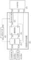
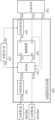
도 1은 본 발명의 일 실시예에 의한 릴레이 제어 장치(100)의 상세 구성을 도시한 블록도, 도 2 및 도 3은 도 1에 도시된 릴레이상태결정부(130)의 상세 구성을 도시한 블록도이다.FIG. 1 is a block diagram showing a detailed configuration of a relay control device (100) according to one embodiment of the present invention, and FIGS. 2 and 3 are block diagrams showing a detailed configuration of a relay status determination unit (130) shown in FIG. 1.
우선, 도 1 및 이와 관련된 도면 등을 참조하여 본 발명에 의한 릴레이 제어 장치(100)의 세부 구성과 이들 구성이 수행하는 프로세싱에 대하여 상세히 설명하고, 릴레이상태결정부(130)에 대한 상세한 내용은 후술하도록 한다.First, with reference to FIG. 1 and related drawings, etc., the detailed configuration of the relay control device (100) according to the present invention and the processing performed by these configurations will be described in detail, and the relay status determination unit (130) will be described in detail later.
도 1에 예시된 바와 같이 본 발명의 릴레이 제어 장치(100)는 프로세서(110), 모니터링부(120) 및 릴레이상태결정부(130)를 포함하여 구성될 수 있다.As illustrated in Fig. 1, the relay control device (100) of the present invention may be configured to include a processor (110), a monitoring unit (120), and a relay status determination unit (130).
구체적으로 상기 릴레이상태결정부(130)는 실시형태에 따라서 도 2 및 도 3에 예시된 바와 같이, 플립플롭(131), 버퍼부(132) 및 게이트부를 포함하여 구성될 수 있다.Specifically, the relay status determination unit (130) may be configured to include a flip-flop (131), a buffer unit (132), and a gate unit, as illustrated in FIGS. 2 and 3, depending on the embodiment.
본 발명의 릴레이 제어 장치(100)는 프로세서(110)의 모니터링 결과에 따른 신호 체계 및 릴레이(200)의 작동 제어를 위하여 프로세서(110)가 원래적으로 출력하는 신호(이하 '기초제어신호'라 지칭한다)를 유기적으로 접목하여 릴레이(200)를 최종 제어하는 신호(이하 '릴레이제어신호'라 지칭한다)를 출력함으로써 릴레이(200)의 온오프를 제어하는 장치에 해당한다.The relay control device (100) of the present invention is a device that controls the on/off of a relay (200) by organically combining a signal originally output by the processor (110) (hereinafter referred to as a “basic control signal”) to control the operation of the relay (200) and a signal system based on the monitoring results of the processor (110) to output a signal (hereinafter referred to as a “relay control signal”) that finally controls the relay (200).
도면에는 고전압측 릴레이인 하이 사이드 릴레이(high side relay)에 해당하는 제1릴레이(210) 및 저전압측 릴레이인 로우 사이드 릴레이(low side relay)에 해당하는 제2릴레이(220)가 도시되어 있으나 이는 하나의 예로서 이와는 다른 개수와 종류의 릴레이(200)가 적용될 수 있음은 물론이다.The drawing shows a first relay (210) corresponding to a high side relay, which is a high voltage side relay, and a second relay (220) corresponding to a low side relay, which is a low voltage side relay, but this is only an example and it is obvious that a different number and type of relay (200) may be applied.
릴레이 제어 장치(100)에 구비되는 프로세서(110)는 본 발명에서 수행되는 다양한 제어 로직들을 실행하기 위한 구성으로서, 이 기술분야에서 잘 알려진 ASIC(application-specific integrated circuit), 칩셋, 논리 회로, 레지스터, 통신 모뎀, 데이터 처리 장치 등을 선택적으로 포함할 수 있다.The processor (110) provided in the relay control device (100) is a configuration for executing various control logics performed in the present invention, and may optionally include an ASIC (application-specific integrated circuit), chipset, logic circuit, register, communication modem, data processing device, etc., which are well known in this technical field.
또한, 제어 로직이 소프트웨어로 구현되는 경우, 메모리 등에 저장된 프로그램 모듈의 집합이 프로세서(110)에 의하여 실행됨으로써 구현될 수 있다. 상기 메모리는 프로세서(110) 내부 또는 외부에 있을 수 있고, 잘 알려진 다양한 수단으로 프로세서(110)와 통신 가능하게 연결될 수 있다.In addition, when the control logic is implemented as software, it can be implemented by executing a set of program modules stored in a memory, etc., by the processor (110). The memory can be located inside or outside the processor (110) and can be communicatively connected to the processor (110) by various well-known means.
본 발명의 상세한 설명에 앞서, 본 발명에 의한 릴레이 제어 장치(100) 및 릴레이상태결정부(130) 등은 저장수단, 연산처리수단, 입출력수단 등과 같은 전자소자, 부품 등의 다양한 조합적 적용을 통하여 구현될 수 있음은 자명하므로 도 1에 도시된 릴레이 제어 장치(100) 그리고 도 2 등에 도시된 릴레이상태결정부(130)의 각 구성요소는 물리적으로 구분되는 구성요소라기보다는 기능적 또는 논리적으로 구분되는 구성요소로 이해되어야 한다.Before going into a detailed description of the present invention, it is obvious that the relay control device (100) and the relay state determination unit (130) according to the present invention can be implemented through various combinational applications of electronic devices, parts, etc., such as storage means, operation processing means, input/output means, etc. Therefore, each component of the relay control device (100) illustrated in FIG. 1 and the relay state determination unit (130) illustrated in FIG. 2, etc. should be understood as functionally or logically distinct components rather than physically distinct components.
즉, 상기 도면에 도시된 각각의 구성요소는 본 발명에 의한 기술사상을 효과적으로 설명하기 위한 논리적 구성에 해당하므로 각각의 구성요소가 통합 또는 분리되어 구성되더라도 본 발명의 논리 구성이 수행하는 기능이 실현될 수 있다면 본 발명의 범위 내에 있다고 해석되어야 하며, 동일 또는 유사한 기능을 수행하는 구성요소라면 그 명칭상의 일치성 여부와는 무관히 본 발명의 범위 내에 있다고 해석되어야 함은 물론이다.That is, since each component illustrated in the above drawing corresponds to a logical configuration for effectively explaining the technical idea of the present invention, even if each component is configured integrated or separately, if the function performed by the logical configuration of the present invention can be realized, it should be interpreted as being within the scope of the present invention, and if it is a component that performs the same or similar function, it should be interpreted as being within the scope of the present invention regardless of the consistency in their names.
본 발명에 의한 릴레이 제어 장치(100)는 기본적으로 프로세서(110)의 동작상태가 정상상태인 경우, 프로세서(110)가 출력하는 기초제어신호(CS)에 기반하여, 릴레이(200)를 최종적으로 제어하는 신호인 릴레이제어신호(RCS)를 릴레이(200)로 출력함으로써 해당 릴레이(200)의 온오프가 제어되도록 구성된다.The relay control device (100) according to the present invention is basically configured to control the on/off of the relay (200) by outputting a relay control signal (RCS), which is a signal that ultimately controls the relay (200), to the relay (200) based on a basic control signal (CS) output by the processor (110) when the operating state of the processor (110) is normal.
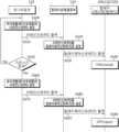
구체적으로 제1릴레이(210)를 제어하기 위한 제1기초제어신호(CS1) 및 제2릴레이(220)를 제어하기 위한 제2기초제어신호(CS2)가 프로세서(110)에 의하여 출력되면(S400, 도 4 참조), 이들 신호를 기반으로 하는 제1릴레이제어신호(RCS1) 및 제2릴레이제어신호(RCS2) 각각이 제1릴레이(210) 및 제2릴레이(220)로 출력됨으로써(S455) 제1릴레이(210) 및 제2릴레이(220)의 온오프가 제어된다(S460).Specifically, when a first basic control signal (CS1) for controlling the first relay (210) and a second basic control signal (CS2) for controlling the second relay (220) are output by the processor (110) (S400, see FIG. 4), the first relay control signal (RCS1) and the second relay control signal (RCS2) based on these signals are output to the first relay (210) and the second relay (220), respectively (S455), thereby controlling the on/off of the first relay (210) and the second relay (220) (S460).
릴레이(200)는 단계별 제어 또는 선형 제어 등이 아닌 온/오프(ON/OFF) 방식으로 제어되므로 상기 기초제어신호(CS) 또는/및 릴레이제어신호(RCS)는 기설정된 레퍼런스(reference)를 기준으로 이보다 높은 신호 레벨(하이 레벨 또는 제2신호레벨)을 가지거나 이보다 낮은 신호 레벨(로우 레벨 또는 제1신호레벨)을 가지도록 구성될 수 있다.Since the relay (200) is controlled in an ON/OFF manner rather than in a step-by-step control or linear control, the basic control signal (CS) or/and the relay control signal (RCS) can be configured to have a higher signal level (high level or second signal level) or lower signal level (low level or first signal level) than a preset reference.
실시형태에 따라서 상기 기초제어신호(CS) 또는/및 릴레이제어신호(RCS) 등은 샘플링(sampling) 및 양자화(quantization) 등의 프로세싱을 통하여 디지털 신호 체계를 가질 수도 있음은 물론이다.Depending on the embodiment, the basic control signal (CS) or/and the relay control signal (RCS) may of course have a digital signal system through processing such as sampling and quantization.
또한, 간단한 회로 구성이나 게이트 등을 이용하여 입력 신호를 반전시켜 출력할 수 있으므로 하이 레벨(로우 레벨)의 신호는 언제든지 로우 레벨(하이 레벨)의 신호로 변환될 수 있다.In addition, since the input signal can be inverted and output using a simple circuit configuration or gate, a high level (low level) signal can be converted into a low level (high level) signal at any time.
그러므로 특정 레벨의 신호가 특정 동작에 맵핑되어 있다고 하더라도 이와 반대되는 레벨의 신호를 이용하여 동일한 특정 동작이 제어될 수 있음은 통상의 기술자 수준에서 자명하다고 해석되어야 한다.Therefore, it should be interpreted as being self-evident at the level of ordinary technicians that even if a signal of a certain level is mapped to a certain action, the same specific action can be controlled using a signal of the opposite level.
이러한 해석 기준은 후술되는 신호, 구체적으로 릴레이(200)의 동작상태를 유지하기 위하여 본 발명의 모니터링부(120)에서 출력되는 리테인신호(RS, Retain Signal) 및 프로세서(110)의 동작상태에 따라 차등적인 신호레벨을 가지는 결정제어신호(DS, Decision-control Signal) 등에서도 동일하게 적용될 수 있음은 물론이다.It goes without saying that these interpretation criteria can be equally applied to signals described below, specifically, to a retain signal (RS) output from the monitoring unit (120) of the present invention to maintain the operating state of the relay (200) and a decision-control signal (DS) having a differential signal level depending on the operating state of the processor (110).
본 발명의 프로세서(110)는 앞서 설명된 기초제어신호(CS)와는 별개로 자신의 동작상태에 따라 차등적인 신호레벨을 가지는 제1결정제어신호(DS1)를 출력한다(S420). 상기 제1결정제어신호(DS1)는 본 발명의 릴레이상태결정부(130)가 릴레이(200)를 제어하기 위하여 최종적으로 출력하는 릴레이제어신호(RCS)를 결정하는데 이용되는 신호이다. 이에 대한 상세한 내용은 후술하도록 한다.The processor (110) of the present invention outputs a first decision control signal (DS1) having a differential signal level according to its own operating state separately from the basic control signal (CS) described above (S420). The first decision control signal (DS1) is a signal used to determine the relay control signal (RCS) that the relay state determination unit (130) of the present invention finally outputs to control the relay (200). Details thereof will be described later.
본 발명의 모니터링부(120)는 프로세서(110)의 동작상태(정상상태 또는 리셋상태 등)를 모니터링하는 구성으로서 개별 신호 체계를 구현하기 위하여 프로세서(110)와 독립된 구성으로 설계되는 것이 바람직하다.The monitoring unit (120) of the present invention is configured to monitor the operating state (normal state or reset state, etc.) of the processor (110), and is preferably designed as a configuration independent from the processor (110) in order to implement an individual signal system.
본 발명의 모니터링부(120)는 프로세서(110)의 동작상태를 모니터링하고 상기 프로세서(110)의 동작상태에 따라 차등적인 신호레벨을 가지는 제2결정제어신호(DS2)를 출력한다(S420).The monitoring unit (120) of the present invention monitors the operating state of the processor (110) and outputs a second decision control signal (DS2) having a differential signal level according to the operating state of the processor (110) (S420).
일 예로, 본 발명의 모니터링부(120)는 프로세서(110)의 동작상태가 정상상태인 경우 하이 레벨(제2신호레벨)의 제2결정제어신호(DS2)를, 프로세서(110)의 동작상태가 리셋상태인 경우 로우 레벨(제1신호레벨)의 제2결정제어신호(DS2)를 출력하도록 구성될 수 있다. 앞서 설명된 프로세서(110)가 출력하는 제1결정제어신호(DS1) 또한, 이와 같다.For example, the monitoring unit (120) of the present invention may be configured to output a second decision control signal (DS2) of a high level (second signal level) when the operating state of the processor (110) is a normal state, and to output a second decision control signal (DS2) of a low level (first signal level) when the operating state of the processor (110) is a reset state. The first decision control signal (DS1) output by the processor (110) described above is also the same.
또한, 본 발명의 모니터링부(120)는 상기 제2결정제어신호(DS2)와는 독립적으로 릴레이(200)의 동작상태를 유지하기 위한 리테인신호(RS)를 출력하도록 구성된다(S410). 상기 리테인신호(RS)는 실시형태 또는 제어의 주된 목적성 등에 따라서 신호레벨을 다르게 구성할 수 있다.In addition, the monitoring unit (120) of the present invention is configured to output a retain signal (RS) for maintaining the operating state of the relay (200) independently of the second decision control signal (DS2) (S410). The retain signal (RS) may be configured to have different signal levels depending on the embodiment or the main purpose of control.
구체적으로 프로세서(110)가 리셋상태일 때, 릴레이(200)의 이전 상태와는 무관히 릴레이(200)가 온(ON)상태가 되도록 하고 이를 지속시키는 실시예의 경우, 상기 리테인신호(RS)는 지속적으로 하이 레벨(제2신호레벨)을 가지도록 구성될 수 있다(도 7 참조).Specifically, in the case of an embodiment in which the relay (200) is turned on and maintained regardless of the previous state of the relay (200) when the processor (110) is in a reset state, the retain signal (RS) may be configured to have a continuously high level (second signal level) (see FIG. 7).
또한, 리테인신호(RS)는 실시형태에 따라서 프로세서(110)가 정상상태일 때는 로우 레벨을, 프로세서(110)가 리셋상태인 경우 하이 레벨을 가지도록 구성될 수 있다(도 8 참조).Additionally, the retain signal (RS) may be configured to have a low level when the processor (110) is in a normal state and a high level when the processor (110) is in a reset state, depending on the embodiment (see FIG. 8).
에너지효율을 높이고 과충방전 등을 억제하고자 하는 실시예의 경우, 기준시간 이후 릴레이(200)를 오프시키기 위하여 프로세서(110)의 리셋상태가 유지되는 기준시간 동안은 리테인신호(RS)의 신호 레벨이 하이 레벨(제2신호레벨)이 되도록 하되, 기준시간 이후에는 상기 리테인신호(RS)의 신호 레벨이 로우 레벨(제1신호레벨)이 되도록 구성할 수 있다(도 9 참조).In an embodiment of the present invention, in order to increase energy efficiency and suppress overcharge/discharge, etc., the signal level of the retain signal (RS) may be configured to be a high level (second signal level) during a reference time during which the reset state of the processor (110) is maintained in order to turn off the relay (200) after a reference time, but the signal level of the retain signal (RS) may be configured to be a low level (first signal level) after the reference time (see FIG. 9).
프로세서(110)가 정상상태(리셋상태 직전)일 때의 릴레이(200) 상태를 리셋상태에서도 유지하는 실시예의 경우 즉, 릴레이(200)가 온(ON)인 경우 온(ON)으로 유지하고, 릴레이(200)가 오프(OFF)인 경우 오프(OFF)로 유지하고자 하는 실시예의 경우, 본 발명의 모니터링부(120)는 리셋상태 직전의 정상상태일 때 프로세서(110)에 의하여 출력되는 기초제어신호(CS)와 상응하는 신호레벨을 가지는 리테인신호(RS)를 출력하도록 구성될 수 있다.In the case of an embodiment in which the state of the relay (200) when the processor (110) is in a normal state (just before the reset state) is maintained even in the reset state, that is, in the case of an embodiment in which the relay (200) is to be maintained in an ON state when it is ON and in an OFF state when the relay (200) is OFF, the monitoring unit (120) of the present invention may be configured to output a retain signal (RS) having a signal level corresponding to the basic control signal (CS) output by the processor (110) when it is in a normal state just before the reset state.
한편, 본 발명의 모니터링부(120)에 의하여 출력되어 본 발명의 릴레이상태결정부(130)로 입력되는 상기 제2결정제어신호(DS2) 및 프로세서(110)에 의하여 출력되어 본 발명의 릴레이상태결정부(130)로 입력되는 제1결정제어신호(DS1)는 릴레이상태결정부(130)에서 어떤 신호를 출력할지 여부를 결정하는 신호로 기능한다.Meanwhile, the second decision control signal (DS2) output by the monitoring unit (120) of the present invention and input to the relay status determination unit (130) of the present invention and the first decision control signal (DS1) output by the processor (110) and input to the relay status determination unit (130) of the present invention function as signals that determine which signal to output from the relay status determination unit (130).
본 발명의 릴레이상태결정부(130)는 릴레이(200)를 최종적으로 제어하기 위한 신호인 릴레이제어신호(RCS)를 결정하고 결정된 릴레이제어신호(RCS)를 릴레이(200)로 출력하는 구성에 해당한다.The relay status determination unit (130) of the present invention corresponds to a configuration that determines a relay control signal (RCS), which is a signal for ultimately controlling the relay (200), and outputs the determined relay control signal (RCS) to the relay (200).
구체적으로 본 발명의 릴레이상태결정부(130)는 프로세서(110)로부터 기초제어신호(CS)와 제1결정제어신호(DS1)를 입력받으며, 모니터링부(120)로부터 제2결정제어신호(DS2)와 리테인신호(RS)를 입력받는다.Specifically, the relay status determination unit (130) of the present invention receives a basic control signal (CS) and a first decision control signal (DS1) from the processor (110), and receives a second decision control signal (DS2) and a retain signal (RS) from the monitoring unit (120).
이와 같이 4가지 종류의 신호(기초제어신호(CS), 리테인신호(RS), 제1결정제어신호(DS1) 및 제2결정제어신호(DS2))가 본 발명의 릴레이상태결정부(130)로 입력되면 본 발명의 릴레이상태결정부(130)는 제1 및 제2결정제어신호(DS1, DS2)의 신호레벨이 하이 레벨인지 또는 로우 레벨인지 여부에 따라 기초제어신호(CS)와 리테인신호(RS) 중 하나를 릴레이제어신호(RCS)로 출력한다(S450, S460).When four types of signals (basic control signal (CS), retain signal (RS), first decision control signal (DS1), and second decision control signal (DS2)) are input to the relay state determination unit (130) of the present invention, the relay state determination unit (130) of the present invention outputs one of the basic control signal (CS) and the retain signal (RS) as a relay control signal (RCS) depending on whether the signal levels of the first and second decision control signals (DS1, DS2) are high or low (S450, S460).
앞서 기술된 바와 같이 제1 및 제2결정제어신호(DS1, DS2)는 프로세서(110)의 동작상태(정상상태 또는 리셋상태)에 따라 차등적인 신호레벨을 가지므로 상기 제1 및 제2결정제어신호(DS1, DS2)는 프로세서(110)의 현재 시점의 동작상태를 표상한다.As described above, the first and second decision control signals (DS1, DS2) have differential signal levels depending on the operating state (normal state or reset state) of the processor (110), so the first and second decision control signals (DS1, DS2) represent the operating state of the processor (110) at the current point in time.
즉, 본 발명의 모니터링부(120)는 상기 프로세서(110)의 동작상태가 리셋상태인 경우, 상기 프로세서(110)가 정상상태인 경우 출력되는 상기 제2결정제어신호(DS2)와 다른 신호레벨을 가지는 제2결정제어신호(DS2)를 출력한다. 프로세서(110)에 의하여 출력되는 제1결정제어신호(DS1) 또한, 이와 같다.That is, when the operating state of the processor (110) is in a reset state, the monitoring unit (120) of the present invention outputs a second decision control signal (DS2) having a different signal level from the second decision control signal (DS2) output when the processor (110) is in a normal state. The first decision control signal (DS1) output by the processor (110) is also the same.
이하 설명에서는 상대적 구분을 명확하기 하기 위하여 프로세서(110)의 동작상태가 리셋상태인 경우 출력되는 제1 및 제2결정제어신호(DS1, DS2)를 각각 '제1 및 제2전환제어신호'로 지칭한다.In the following description, in order to make the relative distinction clear, the first and second decision control signals (DS1, DS2) output when the operating state of the processor (110) is in the reset state are referred to as the 'first and second switching control signals', respectively.
본 발명의 릴레이상태결정부(130)는 모니터링부(120)로부터 입력된 제2결정제어신호(DS2)가, 제2전환제어신호(DS2) 즉, 프로세서(110)의 동작상태가 리셋상태임을 표상하는 신호(예를 들어 로우 레벨(제1신호레벨)의 신호)인 경우, 기초제어신호(CS)와 리테인신호(RS) 중 리테인신호(RS)를 릴레이제어신호(RCS)로 출력하도록 구성될 수 있다.The relay status determination unit (130) of the present invention may be configured to output the retain signal (RS) among the basic control signal (CS) and the retain signal (RS) as the relay control signal (RCS) when the second decision control signal (DS2) input from the monitoring unit (120) is a signal (e.g., a low level (first signal level)) representing that the operating state of the processor (110) is a reset state.
바람직한 실시형태의 구현을 위하여, 본 발명의 릴레이상태결정부(130)는 프로세서(110)로부터 입력된 제1결정제어신호(DS1)가 제1전환제어신호(DS1) 즉, 프로세서(110)의 동작상태가 리셋상태임을 표상하는 신호(예를 들어 로우 레벨(제1신호레벨)의 신호)인지 여부를 추가적으로 확인하도록 구성될 수 있다.In order to implement a preferred embodiment, the relay state determination unit (130) of the present invention may be configured to additionally check whether the first decision control signal (DS1) input from the processor (110) is a first switching control signal (DS1), i.e., a signal representing that the operating state of the processor (110) is a reset state (e.g., a signal of low level (first signal level)).
이에 대한 일 예로서, 본 발명의 릴레이상태결정부(130)는 제1결정제어신호(DS1) 및 제2결정제어신호(DS2)를 연산하고 그 연산된 결과신호의 신호레벨에 기반하여(S430, S440) 기초제어신호(CS) 및 리테인신호(RS) 중 하나를 상기 릴레이제어신호(RCS)로 출력하도록 구성될 수 있다(S450, S455).As an example of this, the relay status determination unit (130) of the present invention may be configured to calculate the first decision control signal (DS1) and the second decision control signal (DS2) and output one of the basic control signal (CS) and the retain signal (RS) as the relay control signal (RCS) based on the signal level of the calculated result signal (S430, S440) (S450, S455).
구체적으로 본 발명의 릴레이상태결정부(130)는 프로세서(110)가 출력하는 제1전환제어신호(DS1) 및 모니터링부(120)가 출력하는 제2전환제어신호(DS2) 모두가 수신되는 경우에 한해, 리테인신호(RS)를 릴레이제어신호(RCS)로 출력하도록(S450) 구성될 수 있다.Specifically, the relay status determination unit (130) of the present invention may be configured to output the retain signal (RS) as the relay control signal (RCS) only when both the first switching control signal (DS1) output by the processor (110) and the second switching control signal (DS2) output by the monitoring unit (120) are received (S450).
이와 같이 제1 및 제2전환제어신호(DS1, DS2)가 수신된다는 것은 프로세서(110)는 물론, 프로세서(110)와 독립된 구성으로 구현되는 모니터링부(120) 모두에서 프로세서(110)가 현재 리셋상태임을 표상하는 신호를 출력한 것이므로 현재 프로세서(110)가 리셋상태임을 더욱 명확히 확인할 수 있다.In this way, the fact that the first and second switching control signals (DS1, DS2) are received means that both the processor (110) and the monitoring unit (120) implemented as an independent configuration from the processor (110) output a signal indicating that the processor (110) is currently in a reset state, so that it can be more clearly confirmed that the processor (110) is currently in a reset state.
이와 같이 현재 프로세서(110)가 리셋상태인 경우 앞서 설명된 바와 같이 본 발명의 릴레이상태결정부(130)는 기초제어신호(CS) 및 리테인신호(RS) 중 리테인신호(RS)를 릴레이제어신호(RCS)로 출력한다(S450).In this way, when the current processor (110) is in a reset state, as described above, the relay state determination unit (130) of the present invention outputs the retain signal (RS) among the basic control signal (CS) and the retain signal (RS) as a relay control signal (RCS) (S450).
이와는 달리, 본 발명의 릴레이상태결정부(130)는 프로세서(110)로부터 제1전환제어신호(DS1)가 수신되지 않거나 모니터링부(120)로부터 제2전환제어신호(DS2)가 수신되지 않는 경우, 기초제어신호(CS)와 리테인신호(RS) 중 기초제어신호(CS)를 릴레이제어신호(RCS)로 출력한다(S455).In contrast, when the first switching control signal (DS1) is not received from the processor (110) or the second switching control signal (DS2) is not received from the monitoring unit (120), the relay status determination unit (130) of the present invention outputs the basic control signal (CS) among the basic control signal (CS) and the retain signal (RS) as the relay control signal (RCS) (S455).
이 경우는 프로세서(110) 및 모니터링부(120) 각각으로부터 입력된 제1 또는 제2결정제어신호(DS1, DS2)가 프로세서(110)의 동작상태가 정상상태임을 표상하는 신호(예를 들어 하이 레벨(제2신호레벨)의 신호)인 경우에 해당한다.This case corresponds to a case where the first or second decision control signal (DS1, DS2) input from each of the processor (110) and the monitoring unit (120) is a signal (e.g., a signal of high level (second signal level)) indicating that the operating state of the processor (110) is normal.
실시형태에 따라서 모니터링부(120)가 출력하는 제2결정제어신호(DS2)에 우선권(priority)을 부여할 수 있다. 이러한 실시 구성에 의하는 경우, 프로세서(110)로부터 제1전환제어신호(DS1)가 입력되지 않았으나, 모니터링부(120)로부터 제2전환제어신호(DS2)가 입력되는 경우 프로세서(110)를 리셋상태로 간주하여 기초제어신호(CS)와 리테인신호(RS) 중 리테인신호(RS)를 릴레이제어신호(RCS)로 출력하도록 구성될 수 있다.According to an embodiment, priority may be given to the second decision control signal (DS2) output by the monitoring unit (120). In the case of such an implementation configuration, when the first switching control signal (DS1) is not input from the processor (110), but the second switching control signal (DS2) is input from the monitoring unit (120), the processor (110) may be considered to be in a reset state and the retain signal (RS) among the basic control signal (CS) and the retain signal (RS) may be configured to be output as a relay control signal (RCS).
구체적으로 본 발명의 릴레이상태결정부(130)는 제1결정제어신호(DS1) 및 제2결정제어신호(DS2)가 입력되면(S420) 이들을 논리 게이트 등으로 연산한 결과를 결정제어신호(DS)로 출력하고(S430), 이 결정제어신호(DS)의 신호레벨이 하이 레벨(제2신호레벨)인지 로우 레벨(제1신호레벨)인지 여부에 따라(S440) 릴레이제어신호(RCS)를 결정하도록 구성될 수 있다.Specifically, the relay state determination unit (130) of the present invention may be configured to output the result of calculating the first decision control signal (DS1) and the second decision control signal (DS2) using a logic gate (S420) as a decision control signal (DS) and determine the relay control signal (RCS) based on whether the signal level of the decision control signal (DS) is a high level (second signal level) or a low level (first signal level) (S440).
도 11에 예시된 바와 같이, 본 발명의 릴레이상태결정부(130)가 제1결정제어신호(DS1) 및 제2결정제어신호(DS2)를 앤드게이트(AND gate)로 연산하도록 구성된 경우, 양 신호 모두가 로우 레벨(제1신호레벨)인 경우에 한해, 로우 레벨을 가지는 결정제어신호(DS)가 출력된다.As illustrated in Fig. 11, when the relay state determination unit (130) of the present invention is configured to operate the first decision control signal (DS1) and the second decision control signal (DS2) as an AND gate, the decision control signal (DS) having a low level is output only when both signals are at a low level (first signal level).
앞서 정의된 바로 환언하면, 프로세서(110)로부터 제1전환제어신호(DS1)가 입력되고, 모니터링부(120)로부터 제2전환제어신호(DS2)가 수신되는 경우에 한해 프로세서(110)가 리셋상태임을 표상하는 결정제어신호(DS)(이하 '전환제어신호'로 지칭한다)가 출력된다.In other words, as defined above, a decision control signal (DS) (hereinafter referred to as a 'transition control signal') indicating that the processor (110) is in a reset state is output only when a first transition control signal (DS1) is input from the processor (110) and a second transition control signal (DS2) is received from the monitoring unit (120).
이하에서는 도 11에 예시된 바와 같이 제1결정제어신호(DS1) 및 제2결정제어신호(DS2) 모두가 로우 레벨인 경우에 한해, 로우 레벨의 결정제어신호(DS)(전환제어신호)가 출력되도록 구성된 실시예를 기준으로 설명한다.Hereinafter, an embodiment is described in which a low-level decision control signal (DS) (transition control signal) is output only when both the first decision control signal (DS1) and the second decision control signal (DS2) are at low levels, as illustrated in FIG. 11.
이와 같이 프로세서(110)의 동작상태가 정확히 반영되어 생성되는 릴레이제어신호(RCS)가 릴레이(200)로 출력되면 본 발명의 릴레이(200)는 입력된 상기 릴레이제어신호(RCS)에 의하여 제어된다(S460).When the relay control signal (RCS) generated by accurately reflecting the operating state of the processor (110) is output to the relay (200), the relay (200) of the present invention is controlled by the input relay control signal (RCS) (S460).
상술된 본 발명의 프로세싱은 강제 종료, 전체 시스템의 다운, 긴급 이벤트 발생 등과 같은 미리 설정된 종료 조건이 충족되지 않는다면(S470) 순환적으로 적용될 수 있음은 물론이다.It goes without saying that the processing of the present invention described above can be applied cyclically if a preset termination condition, such as a forced termination, a total system down, or an emergency event occurring, is not met (S470).
릴레이(200)가 제1릴레이(210) 및 제2릴레이(220)로 이루어지는 경우, 본 발명의 릴레이상태결정부(130)는 결정제어신호(DS)의 신호레벨에 따라 제1기초제어신호(CS1) 및 리테인신호(RS) 중 하나로 정해지는 제1릴레이제어신호(RCS1)를 제1릴레이(210)로 출력하며, 상응하는 관점에서 결정제어신호(DS)의 신호레벨에 따라 제2기초제어신호(CS2)와 리테인신호(RS) 중 하나로 정해지는 제2릴레이제어신호(RCS2)를 제2릴레이(220)로 출력한다.When the relay (200) is composed of a first relay (210) and a second relay (220), the relay status determination unit (130) of the present invention outputs a first relay control signal (RCS1) determined as one of a first basic control signal (CS1) and a retain signal (RS) according to the signal level of the decision control signal (DS) to the first relay (210), and from a corresponding viewpoint, outputs a second relay control signal (RCS2) determined as one of a second basic control signal (CS2) and a retain signal (RS) according to the signal level of the decision control signal (DS) to the second relay (220).
이하에서는 상술된 본 발명의 실시예에 대한 내용을 도 7을 참조하여 보충적으로 설명한다. 도 7은 정상상태 및 리셋상태 각각에 따른 본 발명의 일 실시예에 의한 신호 체계를 설명하는 도면이다.Hereinafter, the contents of the embodiment of the present invention described above will be supplementarily described with reference to FIG. 7. FIG. 7 is a drawing explaining a signal system according to one embodiment of the present invention according to each of a normal state and a reset state.
도 7의 t1은 시스템 오류 등에 의하여 프로세서(110)(MCU 등)의 리셋상태가 시작되는 시점을 예시하며, t2는 리셋상태 이후 프로세서(110)가 정상상태로 복원된 시점을 예시한다.t1 of Fig. 7 exemplifies the point in time when the reset state of the processor (110) (MCU, etc.) begins due to a system error, etc., and t2 exemplifies the point in time when the processor (110) is restored to a normal state after the reset state.
도 7에 예시된 바와 같이 프로세서(110)가 초기 정상상태(Normal State)인 경우, 제1 및 제2결정제어신호(DS1, DS2) 모두가 하이 레벨이므로 결정제어신호(DS) 또한, 하이 레벨의 신호가 된다. 본 발명의 릴레이상태결정부(130)는 이 결정제어신호(DS)에 기반하여 프로세서(110)로부터 입력된(S400) 기초제어신호(CS)와 모니터링부(120)로부터 입력된(S410) 리테인신호(RS) 중 기초제어신호(CS)를 릴레이제어신호(RCS)로 출력한다(S455).As illustrated in Fig. 7, when the processor (110) is in the initial normal state, since both the first and second decision control signals (DS1, DS2) are high levels, the decision control signal (DS) also becomes a high level signal. The relay state determination unit (130) of the present invention outputs the basic control signal (CS) among the basic control signal (CS) input from the processor (110) (S400) and the retain signal (RS) input from the monitoring unit (120) (S410) as a relay control signal (RCS) based on the decision control signal (DS) (S455).
그러므로 프로세서(110)가 초기 정상상태인 ~t1까지 릴레이(200)를 최종적으로 제어하는 릴레이제어신호(RCS)는 기초제어신호(CS)에 기반하게 된다.Therefore, the relay control signal (RCS) that ultimately controls the relay (200) until ~t1, which is the initial normal state of the processor (110), is based on the basic control signal (CS).
프로세서(110)가 t1 시점에 리셋상태가 되는 경우, 모니터링부(120) 및 프로세서(110) 각각은 정상상태일 때의 제1 및 제2결정제어신호(DS1, DS2)와 차등적인 신호레벨(예를 들어 로우 레벨(제1신호레벨))을 가지는 제1 및 제2결정제어신호(DS1, DS2) 즉, 제1 및 제2전환제어신호(DS1, DS2)를 출력한다(S420).When the processor (110) is reset at time t1, each of the monitoring unit (120) and the processor (110) outputs first and second decision control signals (DS1, DS2) having differential signal levels (e.g., low levels (first signal levels)) from the first and second decision control signals (DS1, DS2) in the normal state, i.e., first and second transition control signals (DS1, DS2) (S420).
프로세서(110)가 정상상태인 경우에 출력되는 제1 및 제2결정제어신호(DS1, DS2)와 대비하여 차등적인 레벨을 가지는 제1 및 제2결정제어신호(DS1, DS2)인 제1 및 제2전환제어신호(DS1, DS2)가 릴레이상태결정부(130)로 입력되면(S435), 본 발명의 릴레이상태결정부(130)는 모니터링부(120)로부터 입력된 리테인신호(RS)를 릴레이제어신호(RCS)로 출력한다(S450).When the first and second switching control signals (DS1, DS2), which are first and second decision control signals (DS1, DS2) having differential levels compared to the first and second decision control signals (DS1, DS2) output when the processor (110) is in a normal state, are input to the relay state determination unit (130) (S435), the relay state determination unit (130) of the present invention outputs the retain signal (RS) input from the monitoring unit (120) as a relay control signal (RCS) (S450).
그러므로 [t1, t2] 구간에서 릴레이상태결정부(130)에서 출력되는 릴레이제어신호(RCS)는 리테인신호(RS)에 기반하게 된다.Therefore, the relay control signal (RCS) output from the relay status determination unit (130) in the [t1, t2] section is based on the retain signal (RS).
t2 시점에 프로세서(110)가 정상상태로 복원되면 본 발명의 프로세서(110)와 모니터링부(120)는 이를 표상하는 제1 및 제2결정제어신호(DS1, DS2)(예를 들어 하이 레벨)를 출력하고, 이 신호가 수신되면 본 발명의 릴레이상태결정부(130)는 기초제어신호(CS)와 리테인신호(RS) 중 기초제어신호(CS)를 릴레이제어신호(RCS)로 출력한다.When the processor (110) is restored to a normal state at time t2, the processor (110) and the monitoring unit (120) of the present invention output first and second decision control signals (DS1, DS2) (e.g., high level) representing this, and when this signal is received, the relay state determination unit (130) of the present invention outputs the basic control signal (CS) among the basic control signal (CS) and the retain signal (RS) as the relay control signal (RCS).
그러므로 정상상태로 복원된 t2 시점 이후, 본 발명의 릴레이제어신호(RCS)는 다시 기초제어신호(CS)에 기반하게 된다.Therefore, after the time point t2 when the normal state is restored, the relay control signal (RCS) of the present invention becomes based on the basic control signal (CS) again.
도 7에 예시된 실시예는 프로세서(110)의 동작상태 여부와는 무관히 본 발명의 모니터링부(120)가 하이 레벨을 가지는 리테인신호(RS)를 출력하도록 설정된 실시예에 해당한다.The embodiment illustrated in FIG. 7 corresponds to an embodiment in which the monitoring unit (120) of the present invention is set to output a retain signal (RS) having a high level regardless of the operating state of the processor (110).
앞서 설명된 바와 같이 릴레이제어신호(RCS)는 제1 및 제2결정제어신호(DS1, DS2)에 기반하여 기초제어신호(CS)와 리테인신호(RS) 중 하나로 선택적으로 정해진다. 그러므로 이와 같이 리테인신호(RS)가 프로세서(110)의 동작상태 여부와 무관히 하이 레벨을 유지하도록 설정되어도 프로세서(110)가 리셋상태로 전환되는 경우에 한해 리테인신호(RS)가 릴레이제어신호(RCS)로 반영되어 릴레이(200)를 온상태로 유지할 수 있게 된다.As described above, the relay control signal (RCS) is selectively determined as one of the basic control signal (CS) and the retain signal (RS) based on the first and second decision control signals (DS1, DS2). Therefore, even if the retain signal (RS) is set to maintain a high level regardless of the operating state of the processor (110), the retain signal (RS) is reflected as the relay control signal (RCS) only when the processor (110) is switched to a reset state, thereby allowing the relay (200) to be maintained in an on state.
이러한 본 발명의 실시 구성에 의하면, 리테인신호(RS)의 신호레벨을 프로세서(110)의 동작상태에 연계시키지 않고 일정한 신호레벨 수준을 유지하면 되므로 회로 설계를 간단하게 구현할 수 있는 장점이 있다.According to this embodiment of the present invention, there is an advantage in that the circuit design can be implemented simply because the signal level of the retain signal (RS) is maintained at a constant signal level without being linked to the operating state of the processor (110).
도 5는 본 발명의 다른 일 실시예에 의한 프로세싱 과정을 설명하는 흐름도이며, 도 8은 이 실시예에 따른 신호 체계의 일 예를 설명하는 도면이다.FIG. 5 is a flowchart illustrating a processing process according to another embodiment of the present invention, and FIG. 8 is a drawing illustrating an example of a signal system according to this embodiment.
도 5에 도시된 본 발명의 실시예는 앞서 도 4 등을 참조하여 설명된 실시예와 대비하여 프로세서(110)가 리셋상태임이 모니터링되는 경우에 한해, 모니터링부(120)가 하이 레벨의 리테인신호(RS)를 출력하도록 구성된다는 점에서 차이가 있다.The embodiment of the present invention illustrated in FIG. 5 differs from the embodiment described above with reference to FIG. 4, etc. in that the monitoring unit (120) is configured to output a high-level retain signal (RS) only when the processor (110) is monitored to be in a reset state.
프로세서(110)가 정상상태인 경우(S510), 앞서 설명된 바와 같이 하이 레벨의 제1 및 제2결정제어신호(DS1, DS2)가 입력되면(S530), 본 발명의 릴레이상태결정부(130)는 프로세서(110)로부터 입력된(S500) 기초제어신호(CS)를 릴레이제어신호(RCS)로 출력한다(S550). 릴레이(200)는 이와 같이 출력된 릴레이제어신호(RCS)에 의하여 온오프가 제어된다(S560).When the processor (110) is in a normal state (S510), and the first and second decision control signals (DS1, DS2) of a high level are input (S530) as described above, the relay state determination unit (130) of the present invention outputs the basic control signal (CS) input from the processor (110) (S500) as a relay control signal (RCS) (S550). The relay (200) is turned on and off by the relay control signal (RCS) output in this manner (S560).
앞서 설명된 바와 같이 하이 레벨을 가지는 제1 및 제2결정제어신호(DS1, DS2)가 입력되면 릴레이상태결정부(130) 내부에서 이들 신호가 연산된 하이 레벨의 결정제어신호(DS)가 출력되고(S540) 이 결정제어신호(DS)에 기반하여 기초제어신호(CS)가 릴레이제어신호(RCS)로 출력되도록(S550) 구성될 수 있다.As described above, when the first and second decision control signals (DS1, DS2) having high levels are input, the relay state determination unit (130) may be configured to output a high-level decision control signal (DS) calculated from these signals (S540), and to output a basic control signal (CS) as a relay control signal (RCS) based on the decision control signal (DS) (S550).
반면, 프로세서(110)가 리셋상태인 경우(S510), 본 발명의 모니터링부(120)는 하이 레벨(제2신호레벨)의 리테인신호(RS)를 출력한다(S520). 또한, 프로세서(110)가 리셋상태이므로 본 발명의 모니터링부(120)는 로우 레벨(제1신호레벨)의 제2결정제어신호(DS1)를, 본 발명의 프로세서(110)는 로우 레벨(제1신호레벨)의 제1결정제어신호(DS1)를 출력한다(S535).On the other hand, when the processor (110) is in a reset state (S510), the monitoring unit (120) of the present invention outputs a retain signal (RS) of a high level (second signal level) (S520). In addition, since the processor (110) is in a reset state, the monitoring unit (120) of the present invention outputs a second decision control signal (DS1) of a low level (first signal level), and the processor (110) of the present invention outputs a first decision control signal (DS1) of a low level (first signal level) (S535).
이와 같이 로우 레벨의 제1 및 제2결정제어신호(DS1, DS2)가 릴레이상태결정부(130)으로 입력되면 릴레이상태결정부(130)는 기초제어신호(CS)와 리테인신호(RS) 중 리테인신호(RS)를 릴레이제어신호(RCS)로 출력하고(S555) 릴레이(200)는 이 릴레이제어신호(RCS)에 의하여 제어된다(S560).In this way, when the first and second decision control signals (DS1, DS2) of low level are input to the relay state determination unit (130), the relay state determination unit (130) outputs the retain signal (RS) among the basic control signal (CS) and the retain signal (RS) as a relay control signal (RCS) (S555), and the relay (200) is controlled by this relay control signal (RCS) (S560).
이 경우에도 앞서 기술된 바와 같이, 로우 레벨을 가지는 제1 및 제2결정제어신호(DS1, DS2)가 입력되면 릴레이상태결정부(130) 내부에서 이들 신호가 연산된 로우 레벨의 결정제어신호(DS)가 출력되고(S545) 이 결정제어신호(DS)에 기반하여 기초제어신호(CS)가 릴레이제어신호(RCS)로 출력되도록(S555) 구성될 수 있다.In this case, as described above, when the first and second decision control signals (DS1, DS2) having low levels are input, the low-level decision control signal (DS) calculated from these signals is output inside the relay state determination unit (130) (S545), and the basic control signal (CS) is output as the relay control signal (RCS) based on the decision control signal (DS) (S555).
이 실시예의 경우도, 도 8의 아래 부분에 도시된 바와 같이 최초 정상상태(~t1)에서는 기초제어신호(CS)에 기반하여 릴레이제어신호(RCS)가 출력되며, t1~t2 구간에서는 리테인신호(RS)에 기반하여 릴레이제어신호(RCS)가 출력된다.In this embodiment, as shown in the lower part of Fig. 8, in the initial steady state (~t1), the relay control signal (RCS) is output based on the basic control signal (CS), and in the t1 to t2 section, the relay control signal (RCS) is output based on the retain signal (RS).
t2 시점에 프로세서(110)가 정상상태로 복원되면 이를 표상하는 제1 및 제2결정제어신호(DS1, DS2)(예를 들어 하이 레벨)를 출력하고 이 신호가 수신되면 본 발명의 릴레이상태결정부(130)는 기초제어신호(CS)와 리테인신호(RS) 중 기초제어신호(CS)를 릴레이제어신호(RCS)로 출력한다.When the processor (110) is restored to a normal state at time t2, the first and second decision control signals (DS1, DS2) (e.g., high level) representing this are output, and when this signal is received, the relay state determination unit (130) of the present invention outputs the basic control signal (CS) among the basic control signal (CS) and the retain signal (RS) as the relay control signal (RCS).
그러므로 정상상태로 복원된 t2 시점 이후, 본 발명의 릴레이제어신호(RCS)는 다시 기초제어신호(CS)에 기반하게 된다. 도 8에 예시된 바와 같이 이 실시예의 경우 프로세서(110)가 정상상태로 복원되면(t2) 상기 리테인신호(RS)는 로우 레벨로 전환될 수 있다.Therefore, after the time point t2 when the normal state is restored, the relay control signal (RCS) of the present invention becomes based on the basic control signal (CS) again. As illustrated in Fig. 8, in the case of this embodiment, when the processor (110) is restored to the normal state (t2), the retain signal (RS) can be switched to a low level.
한편, 앞서 설명된 바와 같이 본 발명의 리테인신호(RS)는 상기 프로세서(110)의 동작상태가 리셋상태인 경우, 상기 리셋상태 직전의 정상상태에서 상기 프로세서(110)에 의하여 출력되는 상기 기초제어신호(CS)와 상응하는 신호레벨을 가지도록 설정될 수 있다.Meanwhile, as described above, the retain signal (RS) of the present invention can be set to have a signal level corresponding to the basic control signal (CS) output by the processor (110) in a normal state immediately before the reset state when the operating state of the processor (110) is a reset state.
이러한 실시 구성에 의하면, 리셋상태 직전(정상상태)에 릴레이(200)가 개방(open, OFF)되어 있는 경우, 리셋상태에서도 릴레이(200)가 계속 개방되도록 제어할 수 있으며, 리셋상태 직전(정상상태)에 릴레이(200)가 닫혀 있는 경우(closed, ON), 리셋상태에서도 릴레이(200)가 계속 닫힌 상태를 유지하도록 제어할 수 있어 릴레이(200)의 상태를 리셋상태 직전의 정상상태와 동일하게 유지할 수 있어 동작 일관성을 지속시킬 수 있다는 장점을 가질 수 있다.According to this implementation configuration, if the relay (200) is open (open, OFF) immediately before the reset state (normal state), the relay (200) can be controlled to remain open even in the reset state, and if the relay (200) is closed (closed, ON) immediately before the reset state (normal state), the relay (200) can be controlled to remain closed even in the reset state, so that the state of the relay (200) can be maintained identical to the normal state immediately before the reset state, thereby having the advantage of maintaining operational consistency.
도 6은 본 발명의 또 다른 실시예에 의한 프로세싱 과정을 설명하는 흐름도이다. 도 9 및 도 10은 도 6에 도시된 실시예에 의한 신호 체계를 보충적으로 설명하는 도면이다.Fig. 6 is a flowchart illustrating a processing process according to another embodiment of the present invention. Figs. 9 and 10 are drawings supplementarily illustrating a signal system according to the embodiment illustrated in Fig. 6.
도 6에 도시된 프로세싱은 프로세서(110)가 리셋상태에 해당하여 프로세서(110) 및 모니터링부(120) 각각에 의하여 제1 및 제2전환제어신호(DS1, DS2) 즉, 프로세서(110)가 리셋상태임을 표상하는 제1 및 제2결정제어신호(DS1, DS2)가 출력되는 경우를 전제로 한다.The processing illustrated in FIG. 6 is based on the assumption that the processor (110) is in a reset state and the processor (110) and the monitoring unit (120) output first and second switching control signals (DS1, DS2), i.e., first and second decision control signals (DS1, DS2) indicating that the processor (110) is in a reset state.
모니터링부(120)에 의하여 하이 레벨의 리테인신호(RS)가 생성되면(S600) 이 리테인신호(RS)는 릴레이상태결정부(130)로 출력된다(S610). 릴레이상태결정부(130)는 전환제어신호(DS)에 기반하여 리테인신호(RS)로 정해진(S620) 릴레이제어신호(RCS)를 릴레이(200)로 출력한다(S630).When a high level retain signal (RS) is generated by the monitoring unit (120) (S600), this retain signal (RS) is output to the relay status determination unit (130) (S610). The relay status determination unit (130) outputs a relay control signal (RCS) determined as the retain signal (RS) (S620) to the relay (200) based on the switching control signal (DS) (S630).
이와 같은 프로세싱을 통하여 본 발명의 릴레이(200)는 온상태로 제어된다(S640).Through this processing, the relay (200) of the present invention is controlled to an on state (S640).
t1 시점 이후 프로세서(110)가 정상상태로 복원되지 않으면 결정제어신호(DS)는 계속 로우 레벨(제1신호레벨)을 유지하게 되므로 릴레이제어신호(RCS)의 신호 전환이 이루어지지 않는다. 즉, t1 시점 이후로는 하이 레벨을 가지는 리테인신호(RS)에 기반하여 릴레이제어신호(RCS)가 출력되고 이로 인하여 릴레이(200)는 온상태를 지속하게 된다.If the processor (110) is not restored to the normal state after time t1, the decision control signal (DS) continues to maintain a low level (first signal level), so that the signal switching of the relay control signal (RCS) does not occur. That is, after time t1, the relay control signal (RCS) is output based on the retain signal (RS) having a high level, and as a result, the relay (200) continues to be in the on state.
도 9에 예시된 바와 같이, 본 발명의 모니터링부(120)는 프로세서(110)가 리셋상태가 된 시점(t1)을 기준으로 리셋상태가 기준시간(△t) 동안 지속되는 경우, 기준시간(△t) 동안은 리테인신호(RS)를 제2신호레벨(하이 레벨)로 출력하되(S650, S600), 기준시간 이후(t3 이후)에는 리테인신호(RS)의 신호레벨이 제1신호레벨(로우 레벨)이 되도록(S660) 한다.As illustrated in FIG. 9, the monitoring unit (120) of the present invention outputs the retain signal (RS) at a second signal level (high level) during the reference time (△t) when the reset state continues for a reference time (△t) based on the time point (t1) when the processor (110) is in a reset state (S650, S600), but after the reference time (after t3), the signal level of the retain signal (RS) becomes the first signal level (low level) (S660).
이와 같이 t1을 기준으로 기준시간(△t)이 경과된 후 로우 레벨로 전환된 리테인신호(RS)가 릴레이상태결정부(130)로 출력되면(S670), 릴레이상태결정부(130)는 이 리테인신호(RS)를 릴레이제어신호(RCS)로 출력한다(S680, S685).In this way, when the retain signal (RS) that has been switched to a low level after the standard time (△t) has elapsed based on t1 is output to the relay status determination unit (130) (S670), the relay status determination unit (130) outputs the retain signal (RS) as a relay control signal (RCS) (S680, S685).
이와 같이 로우 레벨에 기반한 릴레이제어신호(RCS)가 릴레이(200)로 출력됨으로써 릴레이(200)는 오프(OFF)로 제어된다(S690).In this way, the relay control signal (RCS) based on the low level is output to the relay (200), so that the relay (200) is controlled to OFF (S690).
이러한 본 발명의 실시 구성에 의하면, 기준시간을 경과한 이후에도 프로세서(110)가 정상상태로 복원되지 않는 경우 릴레이(200)를 오프시킬 수 있어 불필요한 에너지 낭비를 방지할 수 있다. 또한, 중장기적 시간 동안 프로세서(110)가 정상상태로 복원되지 않는다는 것은 실제 치명적인 오류나 결함이 발생하였을 가능성을 시사하는 것일 수 있으므로 이러한 본 발명의 실시 구성에 의하여 이에 대한 안전 사고 등이 미연에 방지될 수 있다.According to this embodiment of the present invention, if the processor (110) is not restored to the normal state even after the reference time has elapsed, the relay (200) can be turned off, thereby preventing unnecessary energy waste. In addition, since the fact that the processor (110) is not restored to the normal state for a medium to long period of time may indicate the possibility that an actual fatal error or defect has occurred, safety accidents, etc. can be prevented in advance by this embodiment of the present invention.
도 10은 제어의 대상이 되는 릴레이(200)가 제1릴레이(210) 및 제2릴레이(220)인 경우 생성되거나 출력되는 신호 체계의 예를 도시한 도면으로서, 도 9에 도시된 신호 체계와 실질적으로 동일하다.FIG. 10 is a drawing showing an example of a signal system generated or output when the relay (200) to be controlled is the first relay (210) and the second relay (220), and is substantially the same as the signal system shown in FIG. 9.
도 10에 표기된 D 부분은 프로세서(110)가 정상상태에서 리셋상태로 변환되는 과정에서 발생되는 신호 지연(signal-delay)을 의미한다. 도 7 내지 도 9에서는 이 부분이 생략되어 있다.Part D indicated in Fig. 10 refers to a signal delay that occurs during the process in which the processor (110) is converted from a normal state to a reset state. This part is omitted in Figs. 7 to 9.
도 10에 도시된 제1 및 제2출력신호(Q1, Q2)는 앞서 기술된 결정제어신호(DS)의 신호 전환에 연동하여 출력되는 신호값으로서 본 발명의 릴레이상태결정부(130)가 도 2 및 도 3에 예시된 바와 같이 플립플롭(131)을 포함하여 구성되는 경우 플립플롭(131)에서 출력되는 신호에 해당한다. 이에 대한 설명은 후술하도록 한다.The first and second output signals (Q1, Q2) illustrated in Fig. 10 are signal values output in conjunction with the signal transition of the decision control signal (DS) described above, and correspond to signals output from the flip-flop (131) when the relay state determination unit (130) of the present invention is configured to include a flip-flop (131) as illustrated in Figs. 2 and 3. A description thereof will be given later.
한편, 본 발명의 모니터링부(120)는 리퀘스트에 대한 피드백정보를 이용하여 프로세서(110)의 현재 상태를 판단하는 소프트웨어 모니터링 및 트리거 신호의 수신 여부를 이용하는 하드웨어 모니터링 중 하나 이상의 결과를 이용하여 상기 전환제어신호를 출력하도록 구성될 수 있다.Meanwhile, the monitoring unit (120) of the present invention may be configured to output the switching control signal using the results of at least one of software monitoring that determines the current state of the processor (110) using feedback information for a request and hardware monitoring that uses whether a trigger signal is received.
앞서 기술된 바와 같이 본 발명의 모니터링부(120)는 프로세서(110)의 동작상태가 정상상태가 아닌 즉, 리셋상태인 경우 이를 표상하는 제2결정제어신호(DS2)인 제2전환제어신호(DS2)를 출력하도록 구성된다.As described above, the monitoring unit (120) of the present invention is configured to output a second transition control signal (DS2), which is a second decision control signal (DS2) representing a case where the operating state of the processor (110) is not a normal state, i.e., a reset state.
이 제2전환제어신호(DS2)는 앞서 기술된 바와 같이 릴레이상태결정부(130)에서 릴레이제어신호(RCS)로 정해질 신호를 결정하는 중요한 파라미터신호 중 하나에 해당한다.As described above, this second switching control signal (DS2) corresponds to one of the important parameter signals that determines the signal to be determined as the relay control signal (RCS) in the relay status determination unit (130).
그러므로 본 발명의 모니터링부(120)는 프로세서(110)의 동작상태에 대한 모니터링을 더욱 정밀하게 구현하기 위하여 현재 프로세서(110)의 동작상태를 판단하는 소프트웨어 모니터링(S/W) 및 트리거 신호의 수신 여부를 이용하는 하드웨어 모니터링(H/W) 모두가 실패(fail)되는 경우에 한해 상기 전환제어신호(DS)를 출력하도록 구성되는 것이 바람직하다.Therefore, in order to more precisely implement monitoring of the operating state of the processor (110), it is preferable that the monitoring unit (120) of the present invention be configured to output the switching control signal (DS) only when both the software monitoring (S/W) that determines the current operating state of the processor (110) and the hardware monitoring (H/W) that uses whether a trigger signal is received fail.
소프트웨어 모니터링은 WDT(Window Watchdog) 등을 통해 일정 시간 동안 리퀘스트(질문 등)를 전송하고 이에 부합되는 피드백(답 등)이 수신되는지 여부를 확인하는 방법 등이 적용될 수 있으며, 하드웨어 모니터링은 하나 이상의 라인이나 채널을 할당하여 특정 시그널을 정상적으로 트리거(trigger) 시켜주는지 여부를 확인하는 방법 등이 적용될 수 있다.Software monitoring can be applied by methods such as sending requests (questions, etc.) for a certain period of time through a WDT (Window Watchdog) and checking whether corresponding feedback (answers, etc.) is received, and hardware monitoring can be applied by methods such as allocating one or more lines or channels and checking whether specific signals are normally triggered.
이하에서는 도 2 및 도 3을 참조하며 본 발명에 의한 릴레이 제어 장치(100)의 일 구성인 릴레이상태결정부(130)에 대한 구체적인 실시예를 설명하도록 한다.Hereinafter, with reference to FIGS. 2 and 3, a specific embodiment of a relay status determination unit (130), which is a component of a relay control device (100) according to the present invention, will be described.
도 2 및 도 3에 도시된 바와 같이 본 발명의 릴레이상태결정부(130)는 플립플롭(131), 버퍼부(132) 및 제1게이트부(134)를 포함하여 구성될 수 있다.As shown in FIGS. 2 and 3, the relay status determination unit (130) of the present invention may be configured to include a flip-flop (131), a buffer unit (132), and a first gate unit (134).
플립플롭(flip-flop)(131)은 1비트(bit)의 정보를 보관 및 유지할 수 있는 논리회로로서, 실시형태에 따라서 도 3에 도시된 플립플롭(131)은 D 플립플롭(D flip-flop), RS 플립플롭, JK 플립플롭 또는 T 플립플롭으로 구현될 수 있다.A flip-flop (131) is a logic circuit that can store and maintain 1 bit of information. Depending on the embodiment, the flip-flop (131) illustrated in FIG. 3 can be implemented as a D flip-flop, an RS flip-flop, a JK flip-flop, or a T flip-flop.
플립플롭(131)은 제2기초제어신호(CS2)가 입력되는 데이터단자(D) 및 결정제어신호(DS)가 입력되는 클럭단자(C)를 입력단자로 가질 수 있으며, 제1출력단자(Q) 및 제2출력단자(Q`)를 포함할 수 있다.A flip-flop (131) may have a data terminal (D) to which a second basic control signal (CS2) is input and a clock terminal (C) to which a decision control signal (DS) is input as input terminals, and may include a first output terminal (Q) and a second output terminal (Q`).
제1출력단자(Q)로부터 출력되는 제1출력신호(Q1)는 플립플롭(131)으로 입력되는 신호인 제2기초제어신호(CS2) 및 결정제어신호(DS)의 신호레벨에 따라 결정되며, 제2출력단자(Q`)에서 출력되는 제2출력신호(Q2)는 제1출력신호(Q1)와 반대되는 신호레벨(제1신호레벨 vs. 제2신호레벨)을 가지도록 설계될 수 있다.The first output signal (Q1) output from the first output terminal (Q) is determined according to the signal levels of the second basic control signal (CS2) and the decision control signal (DS), which are signals input to the flip-flop (131), and the second output signal (Q2) output from the second output terminal (Q`) can be designed to have a signal level (first signal level vs. second signal level) opposite to that of the first output signal (Q1).
본 발명의 제1게이트부(134)는 결정제어신호(DS)를 출력하는 구성으로서, 프로세서(110)로부터 제1결정제어신호(DS1)가 입력되고, 모니터링부(120)로부터 제2결정제어신호(DS2)가 입력되면 이들을 연산하여 결정제어신호(DS)를 출력한다. 앞서 기술된 바와 같이 이 제1게이트부(134)는 앤드게이트 또는 앤드게이트와 낫게이트(NOT gate) 등의 조합으로 구현될 수 있다.The first gate unit (134) of the present invention is configured to output a decision control signal (DS). When a first decision control signal (DS1) is input from a processor (110) and a second decision control signal (DS2) is input from a monitoring unit (120), the first gate unit (134) operates on these and outputs a decision control signal (DS). As described above, the first gate unit (134) can be implemented as an AND gate or a combination of an AND gate and a NOT gate.
구체적인 예로, 플립플롭(131)의 내부 설계를 통하여 결정제어신호(DS)가 하이 레벨에서 로우 레벨로 변환되는 경우, 이에 연동하여 제1출력신호(Q1)가 로우 레벨에서 하이 레벨로 변환되도록 구성될 수 있다. 이 경우, 제2출력신호(Q2)는 제1출력신호(Q1)에 반대 레벨을 가지도록 설계되므로 제2출력신호(Q2)는 로우 레벨의 신호가 된다.As a specific example, when the decision control signal (DS) is converted from a high level to a low level through the internal design of the flip-flop (131), the first output signal (Q1) can be configured to be converted from a low level to a high level in conjunction therewith. In this case, the second output signal (Q2) is designed to have an opposite level to the first output signal (Q1), so the second output signal (Q2) becomes a low-level signal.
버퍼부(132)는 프로세서(110)로부터 제1 및 제2기초제어신호(CS1, CS2)를, 플립플롭(131)으로부터 제1 및 제2출력신호(Q1, Q2)를 수신하며, 모니터링부(120)로부터 리테인신호(RS)를 수신한다.The buffer unit (132) receives the first and second basic control signals (CS1, CS2) from the processor (110), the first and second output signals (Q1, Q2) from the flip-flop (131), and the retain signal (RS) from the monitoring unit (120).
버퍼부(132)는 앞서 설명된 본 발명의 기술사상을 구현하는 회로 아키텍쳐를 통하여 제1 및 제2릴레이(210, 220)의 온오프를 최종적으로 각각 제어하는 신호인 제1 및 제2릴레이제어신호(RCS1, RCS1)를 제1 및 제2릴레이(210, 220)로 출력하도록 구성된다.The buffer unit (132) is configured to output the first and second relay control signals (RCS1, RCS1), which are signals that ultimately control the on/off of the first and second relays (210, 220), to the first and second relays (210, 220) through a circuit architecture that implements the technical idea of the present invention described above.
보다 구체적으로 버퍼부(132)는 복수 개 버퍼를 포함할 수 있다. 그 중 하나인 제1버퍼는 리테인신호(RS) 및 제1출력신호(Q1)를 수신하고 제1출력신호(Q1)의 신호레벨에 따라 리테인신호(RS)의 출력 여부가 결정되도록 구성될 수 있다.More specifically, the buffer unit (132) may include a plurality of buffers. One of them, the first buffer, may be configured to receive a retain signal (RS) and a first output signal (Q1) and determine whether to output the retain signal (RS) based on the signal level of the first output signal (Q1).
예를 들어, 제1출력신호(Q1)의 신호레벨이 제2신호레벨(하이 레벨)인 경우 제1버퍼를 통하여 리테인신호(RS)가 출력되고, 제1출력신호(Q1)의 신호레벨이 제1신호레벨(로우 레벨)인 경우 리테인신호(RS)가 출력되지 않도록 설계될 수 있다.For example, when the signal level of the first output signal (Q1) is the second signal level (high level), the retain signal (RS) can be output through the first buffer, and when the signal level of the first output signal (Q1) is the first signal level (low level), the retain signal (RS) can be designed not to be output.
복수 개 버퍼 중 제2버퍼는 제1기초제어신호(CS1) 및 제2출력신호(Q2)를 수신하고 제2출력신호(Q2)의 신호레벨에 따라 제1기초제어신호(CS1)의 출력 여부가 결정되도록 설계될 수 있다.Among the multiple buffers, the second buffer may be designed to receive the first basic control signal (CS1) and the second output signal (Q2), and determine whether to output the first basic control signal (CS1) based on the signal level of the second output signal (Q2).
예를 들어, 제2출력신호(Q2)의 신호레벨이 제2신호레벨(하이 레벨)인 경우 제2버퍼를 통하여 제1기초제어신호(CS1)가 출력되고, 제2출력신호(Q2)의 신호레벨이 제1신호레벨(로우 레벨)인 경우, 제1기초제어신호(CS1)가 출력되지 않도록 설계될 수 있다.For example, when the signal level of the second output signal (Q2) is the second signal level (high level), the first basic control signal (CS1) can be output through the second buffer, and when the signal level of the second output signal (Q2) is the first signal level (low level), the first basic control signal (CS1) can be designed not to be output.
또한, 제1버퍼의 출력 채널(라인)과 제2버퍼의 출력 채널(라인)은 서로 통합되도록 구성될 수 있다. 이 경우, 제1버퍼와 제2버퍼는 앞서 설명된 바와 같이 서로 반대의 신호레벨을 가지는 제1출력신호(Q1)와 제2출력신호(Q2)가 각각 수신되므로 제1버퍼에서 리테인신호(RS)가 출력되는 경우, 제2버퍼에서 제1기초제어신호(CS1)가 출력되지 않도록 할 수 있다.In addition, the output channel (line) of the first buffer and the output channel (line) of the second buffer can be configured to be integrated with each other. In this case, since the first buffer and the second buffer receive the first output signal (Q1) and the second output signal (Q2) having opposite signal levels as described above, it is possible to prevent the first basic control signal (CS1) from being output from the second buffer when the retain signal (RS) is output from the first buffer.
앞서 설명된 바와 같이 제1버퍼에서 리테인신호(RS)가 출력된다는 것은 저1버퍼로 입력되는 제1출력신호(Q1)의 신호레벨이 제2신호레벨(하이 레벨)임을 의미하고, 제2버퍼로 입력되는 제2출력신호(Q2)는 제1출력신호(Q1)의 반대 레벨의 신호레벨인 로우 레벨의 신호임을 의미한다. 이와 같이 제2버퍼에 로우 레벨의 제2출력신호(Q2)가 입력됨으로써 제2버퍼에서 제1기초제어신호(CS1)가 출력되지 않도록 구성된다.As described above, the fact that the retain signal (RS) is output from the first buffer means that the signal level of the first output signal (Q1) input to the first buffer is the second signal level (high level), and the second output signal (Q2) input to the second buffer is a low-level signal that is the opposite level of the first output signal (Q1). In this way, by inputting the second output signal (Q2) at the low level to the second buffer, the first basic control signal (CS1) is configured not to be output from the second buffer.
따라서, 제1 및 제2출력신호(Q1, Q1)의 신호레벨에 따라서 제1기초제어신호(CS1) 및 리테인신호(RS) 중 하나가 버퍼부(132)를 통하여 제1릴레이제어신호(RCS1)로 출력될 수 있게 된다. 앞서 설명된 바와 같이 제1 및 제2출력신호(Q1, Q2)는 프로세서(110) 및 모니터링부(120)가 출력하는 제1 및 제2결정제어신호(DS1, DS2)에 기반하며, 이 제1 및 제2결정제어신호(DS1, DS2)는 프로세서(110)의 동작상태에 기반한다.Accordingly, depending on the signal levels of the first and second output signals (Q1, Q1), one of the first basic control signal (CS1) and the retain signal (RS) can be output as the first relay control signal (RCS1) through the buffer unit (132). As described above, the first and second output signals (Q1, Q2) are based on the first and second decision control signals (DS1, DS2) output by the processor (110) and the monitoring unit (120), and the first and second decision control signals (DS1, DS2) are based on the operating state of the processor (110).
그러므로 본 발명에 의한 릴레이 제어 장치(100)는 '프로세서(110)의 동작상태에 대한 모니터링과 자체 판단, 모니터링 결과에 따른 제1 및 제2결정제어신호(DS1, DS2) 출력, 제1 또는/및 제2출력신호(Q1, Q2) 출력, 제1기초제어신호(CS1)와 리테인신호(RS) 중 하나의 신호 결정, 결정된 신호가 제1릴레이제어신호(RCS1)로 출력'되는 프로세싱을 통하여 최종적으로 제1릴레이(210)의 온오프를 제어한다.Therefore, the relay control device (100) according to the present invention ultimately controls the on/off of the first relay (210) through processing of 'monitoring and self-judgment of the operating state of the processor (110), outputting the first and second decision control signals (DS1, DS2) according to the monitoring results, outputting the first or/and second output signals (Q1, Q2), determining one of the first basic control signal (CS1) and the retain signal (RS), and outputting the determined signal as the first relay control signal (RCS1)'.
이와 같이 본 발명에 의한 릴레이 제어 장치(100)는 제1릴레이(210)를 제어하는 제1릴레이제어신호(RCS1)를 프로세서(110)의 동작상태를 정확히 반영하여 그 동작상태에 따라 서로 다른 이원화된 신호체계로 출력할 수 있다.In this way, the relay control device (100) according to the present invention can accurately reflect the operating state of the processor (110) and output the first relay control signal (RCS1) controlling the first relay (210) as a different dual signal system according to the operating state.
제2릴레이(220)를 최종적으로 제어하는 제2릴레이제어신호(RCS2) 또한, 앞서 설명된 기술구성을 구현하는 복수 개 버퍼(예를 들어 제3버퍼, 제4버퍼 등)을 통하여 제2기초제어신호(CS2) 또는 리테인신호(RS) 중 하나가 선택되는 방식으로 출력될 수 있다. 제3 및 제4버퍼에 대한 내용은 앞서 기술된 제1 및 제2버퍼와 상응하므로 그에 대한 상세한 설명은 생략한다.The second relay control signal (RCS2) that ultimately controls the second relay (220) may also be output in a manner in which one of the second basic control signal (CS2) or the retain signal (RS) is selected through a plurality of buffers (e.g., the third buffer, the fourth buffer, etc.) that implement the technical configuration described above. Since the third and fourth buffers correspond to the first and second buffers described above, a detailed description thereof is omitted.
실시형태에 따라서 본 발명의 릴레이상태결정부(130)는 도 3에 예시된 바와 같이 제1릴레이(210) 및 제2릴레이(220) 중 적어도 하나와 버퍼부(132) 사이를 매개하는 제2게이트부(133)를 더 포함할 수 있다. 도 3은 이에 대한 하나의 예로서 버퍼부(132)와 제2릴레이(220) 사이에 제2게이트부(133)가 구비된 예를 도시하고 있다.According to an embodiment, the relay status determination unit (130) of the present invention may further include a second gate unit (133) that mediates between at least one of the first relay (210) and the second relay (220) and the buffer unit (132), as illustrated in FIG. 3. As an example of this, FIG. 3 illustrates an example in which the second gate unit (133) is provided between the buffer unit (132) and the second relay (220).
제2게이트부(133)는 버퍼부(132)로부터 제3릴레이제어신호(RCS3)를 수신하고, 모니터링부(120)로부터 리테인신호(RS)를 수신하고, 제3릴레이제어신호(RCS3) 및 리테인신호(RS)의 신호 레벨에 기반하여, 제2릴레이제어신호(RCS2)를 제2릴레이(300)로 출력하도록 설계될 수 있다.The second gate unit (133) may be designed to receive a third relay control signal (RCS3) from the buffer unit (132), receive a retain signal (RS) from the monitoring unit (120), and output a second relay control signal (RCS2) to the second relay (300) based on the signal levels of the third relay control signal (RCS3) and the retain signal (RS).
앞선 실시예와 같이, 프로세서(110)의 동작 상태가 리셋 상태인 경우, 버퍼부(132)의 제4버퍼로부터 리테인신호(RS)가 출력될 수 있으므로 제3릴레이 제어신호(RCS3)는 제4버퍼에서 출력되는 리테인신호(RS)일 수 있다.As in the previous example, when the operating state of the processor (110) is a reset state, the retain signal (RS) can be output from the fourth buffer of the buffer unit (132), so the third relay control signal (RCS3) can be the retain signal (RS) output from the fourth buffer.
그러므로 게이트부는 버퍼부(132) 및 모니터링부(120) 각각에서 출력되는 리테인신호(RS)를 수신하므로 게이트부가 앤드게이트(AND gate)로 구현되는 경우, 수신된 양 신호 모두가 하이 레벨인 경우에 한해, 하이 레벨의 신호를 출력하도록 구성되므로 신호체계의 정확성을 더욱 향상시킬 수 있다.Therefore, since the gate section receives the retain signal (RS) output from each of the buffer section (132) and the monitoring section (120), if the gate section is implemented as an AND gate, it is configured to output a high-level signal only when both received signals are high-level, thereby further improving the accuracy of the signal system.
본 발명에 따른 릴레이 제어 장치(100)는, BMS(Battery Management System)에 적용될 수 있다. 즉, 본 발명에 따른 BMS는, 상술한 릴레이 제어 장치(100)를 포함할 수 있다. 이러한 구성에 있어서, 릴레이 제어 장치(100)의 각 구성요소 중 적어도 일부는, 종래 BMS에 포함된 구성의 기능을 보완하거나 추가함으로써 구현될 수 있다. 예를 들어, 릴레이 제어 장치(100)의 프로세서(110), 모니터링부(120) 및 릴레이상태결정부(130)는 BMS의 구성요소로서 구현될 수 있다.The relay control device (100) according to the present invention can be applied to a BMS (Battery Management System). That is, the BMS according to the present invention can include the relay control device (100) described above. In this configuration, at least some of the components of the relay control device (100) can be implemented by supplementing or adding the functions of the components included in the conventional BMS. For example, the processor (110), the monitoring unit (120), and the relay status determination unit (130) of the relay control device (100) can be implemented as components of the BMS.
또한, 본 발명에 따른 릴레이 제어 장치(100)는, 배터리 팩에 구비될 수 있다. 즉, 본 발명에 따른 배터리 팩은, 상술한 릴레이 제어 장치(100) 및 하나 이상의 배터리 셀을 포함할 수 있다. 또한, 배터리 팩은, 전장품(릴레이, 퓨즈 등) 및 케이스 등을 더 포함할 수 있다.In addition, the relay control device (100) according to the present invention may be provided in a battery pack. That is, the battery pack according to the present invention may include the relay control device (100) described above and one or more battery cells. In addition, the battery pack may further include electrical components (relay, fuse, etc.) and a case, etc.
나아가, 본 발명에 따른 릴레이 제어 장치(100)는, 자동차에 구비될 수 있다. 따라서, 릴레이 제어 장치(100)는, 자동차 주행 중에 시스템적인 오류에 의하여 프로세서(110)가 리셋되는 경우에도, 배터리와 자동차를 연결하는 릴레이가 개방되지 않고 닫힌 상태로 유지되도록 릴레이를 제어할 수 있다.Furthermore, the relay control device (100) according to the present invention can be installed in a vehicle. Accordingly, the relay control device (100) can control the relay so that the relay connecting the battery and the vehicle is not opened but kept in a closed state even when the processor (110) is reset due to a systematic error while the vehicle is driving.
이상에서 본 발명은 비록 한정된 실시예와 도면에 의해 설명되었으나, 본 발명은 이것에 의해 한정되지 않으며 본 발명이 속하는 기술분야에서 통상의 지식을 가진 자에 의해 본 발명의 기술사상과 아래에 기재될 특허청구범위의 균등범위 내에서 다양한 수정 및 변형이 가능함은 물론이다.Although the present invention has been described above by means of limited embodiments and drawings, the present invention is not limited thereto, and various modifications and variations are possible by those skilled in the art within the technical idea of the present invention and the scope of equivalents of the patent claims to be described below.
본 발명의 설명과 그에 대한 실시예의 도시를 위하여 첨부된 도면 등은 본 발명에 의한 기술 내용을 강조 내지 부각하기 위하여 다소 과장된 형태로 도시될 수 있으나, 앞서 기술된 내용과 도면에 도시된 사항 등을 고려하여 본 기술분야의 통상의 기술자 수준에서 다양한 형태의 변형 적용 예가 가능할 수 있음은 자명하다고 해석되어야 한다.The drawings attached for the purpose of explaining the present invention and illustrating embodiments thereof may be illustrated in a somewhat exaggerated form in order to emphasize or highlight the technical contents of the present invention. However, it should be interpreted that it is obvious that various modified application examples may be possible at the level of a person skilled in the art in consideration of the contents described above and matters illustrated in the drawings.
또한, 본 발명의 설명에 있어 제1, 제2 또는 상부, 하부 또는 상하 등과 같은 표현은 상호 간의 각 구성(요소)을 상대적으로 구분하기 위하여 사용되는 도구적 개념의 용어일 뿐, 특정의 순서, 우선순위 등을 나타내기 위하여 사용되는 용어이거나, 절대적인 기준에서 각각의 구성(요소)을 물리적으로 구분하기 위하여 사용되는 용어가 아님은 자명하다.In addition, it is obvious that expressions such as first, second, upper, lower, or top and bottom in the description of the present invention are merely instrumental concept terms used to relatively distinguish each component (element) from each other, and are not terms used to indicate a specific order, priority, etc., or terms used to physically distinguish each component (element) on an absolute basis.
100: 릴레이 제어 장치
110: 프로세서
120: 모니터링부
130: 릴레이상태결정부
131: 플립플롭
132: 버퍼부
133: 제2게이트부
134: 제1게이트부
200: 릴레이
210: 제1릴레이
220: 제2릴레이
CS: 기초제어신호
CS1(2): 제1(2)기초제어신호
DS: 결정제어신호
DS1(2): 제1(2)결정제어신호
RS: 리테인신호
RCS: 릴레이제어신호
RCS1(2): 제1(2)릴레이제어신호
Q1(2): 제1(2)출력신호100: Relay control device
110: Processor
120: Monitoring Department
130: Relay status determination unit
131: Flip-flop
132: Buffer section
133: Gate 2
134: Gate 1
200: Relay
210: 1st relay
220: 2nd relay
CS: Basic control signal
CS1(2): 1st(2) Basic Control Signal
DS: Decision control signal
DS1(2): First (2) decision control signal
RS: Retain signal
RCS: Relay Control Signal
RCS1(2): 1st(2) relay control signal
Q1(2): First (2) output signal
Claims (10)
Translated fromKorean상기 프로세서의 동작상태를 모니터링하고, 상기 프로세서의 동작상태에 따라 차등적인 신호레벨을 가지는 제2결정제어신호 및 상기 릴레이의 동작상태를 유지하기 위한 리테인신호를 출력하도록 구성되는 모니터링부; 및
상기 제1 및 제2결정제어신호의 신호레벨에 기반하여, 상기 기초제어신호 및 상기 리테인신호 중 하나를 상기 릴레이의 온오프를 제어하는 릴레이제어신호로 출력하도록 구성되는 릴레이상태결정부를 포함하는 것을 특징으로 하는 릴레이 제어 장치.A processor configured to output a basic control signal for controlling the operation of a relay and a first decision control signal having a differential signal level according to its own operating state;
A monitoring unit configured to monitor the operating state of the processor and output a second decision control signal having a differential signal level according to the operating state of the processor and a retain signal for maintaining the operating state of the relay; and
A relay control device characterized by including a relay state determination unit configured to output one of the basic control signal and the retain signal as a relay control signal that controls on/off of the relay based on the signal levels of the first and second decision control signals.
상기 릴레이상태결정부는,
상기 제1 및 제2결정제어신호를 연산한 결과신호의 신호레벨에 기반하여 상기 기초제어신호 및 상기 리테인신호 중 하나를 상기 릴레이제어신호로 출력하도록 구성되는 것을 특징으로 하는 릴레이 제어 장치.In the first paragraph,
The above relay status determination unit is,
A relay control device characterized in that it is configured to output one of the basic control signal and the retain signal as the relay control signal based on the signal level of the result signal of calculating the first and second decision control signals.
상기 프로세서는,
자신의 동작상태가 리셋상태인 경우, 자신이 정상상태인 경우 출력되는 상기 제1결정제어신호와 다른 신호레벨을 가지는 제1결정제어신호인 제1전환제어신호를 상기 릴레이상태결정부로 출력하도록 구성되고,
상기 모니터링부는,
상기 프로세서의 동작상태가 리셋상태인 경우, 상기 프로세서가 정상상태인 경우 출력되는 상기 제2결정제어신호와 다른 신호레벨을 가지는 제2결정제어신호인 제2전환제어신호를 상기 릴레이상태결정부로 출력하도록 구성되는 것을 특징으로 하는 릴레이 제어 장치.In the first paragraph,
The above processor,
When its operating state is in a reset state, it is configured to output a first switching control signal, which is a first decision control signal having a different signal level from the first decision control signal output when it is in a normal state, to the relay state determination unit.
The above monitoring unit,
A relay control device characterized in that, when the operating state of the processor is a reset state, a second transition control signal, which is a second decision control signal having a different signal level from the second decision control signal output when the processor is in a normal state, is output to the relay state determination unit.
상기 모니터링부는,
리퀘스트에 대한 피드백정보를 이용하는 소프트웨어 모니터링 및 트리거 신호의 수신 여부를 이용하는 하드웨어 모니터링이 모두 페일(fail)인 경우에 한해 상기 제2전환제어신호를 출력하도록 구성되는 것을 특징으로 하는 릴레이 제어 장치.In the third paragraph,
The above monitoring unit,
A relay control device characterized in that it is configured to output the second switching control signal only when both software monitoring using feedback information for a request and hardware monitoring using whether a trigger signal is received fail.
상기 릴레이상태결정부는,
상기 제1 및 제2전환제어신호 중 어느 하나가 수신되지 않는 경우, 상기 기초제어신호를 상기 릴레이제어신호로 출력하고, 상기 제1 및 제2전환제어신호 모두가 수신되는 경우, 상기 리테인신호를 상기 릴레이제어신호로 출력하도록 구성되는 것을 특징으로 하는 릴레이 제어 장치.In the third paragraph,
The above relay status determination unit is,
A relay control device characterized in that when either of the first and second switching control signals is not received, the basic control signal is output as the relay control signal, and when both the first and second switching control signals are received, the retain signal is output as the relay control signal.
상기 모니터링부는,
상기 프로세서의 동작상태가 리셋상태인 경우, 상기 리셋상태 직전의 정상상태에서 상기 프로세서에 의하여 출력되는 상기 기초제어신호와 상응하는 신호레벨을 가지는 상기 리테인신호를 출력하도록 구성되는 것을 특징으로 하는 릴레이 제어 장치.In the first paragraph,
The above monitoring unit,
A relay control device characterized in that it is configured to output the retain signal having a signal level corresponding to the basic control signal output by the processor in a normal state immediately before the reset state when the operating state of the processor is a reset state.
상기 모니터링부는,
상기 프로세서의 리셋상태가 기준시간 동안 지속되는 경우, 상기 리테인신호를 제2신호레벨로 출력하되, 상기 기준시간 이후에는 상기 리테인신호를 제1신호레벨로 출력하도록 구성되는 것을 특징으로 하는 릴레이 제어 장치.In the first paragraph,
The above monitoring unit,
A relay control device characterized in that when the reset state of the processor continues for a reference time, the retain signal is output at a second signal level, but after the reference time, the retain signal is output at a first signal level.
상기 프로세서의 동작상태에 따라 차등적인 신호레벨을 가지는 제2결정제어신호 및 상기 릴레이의 동작상태를 유지하기 위한 리테인신호를 수신하는 제어신호수신단계; 및
상기 제1 및 제2결정제어신호의 신호레벨에 기반하여, 상기 기초제어신호 및 상기 리테인신호 중 하나를 상기 릴레이의 온오프를 제어하는 릴레이제어신호로 출력하는 제어신호출력단계를 포함하는 것을 특징으로 하는 릴레이 제어 방법.A basic signal receiving step for receiving a basic control signal for controlling the operation of a relay and a first decision control signal having a differential signal level according to the operating state of a processor;
A control signal receiving step for receiving a second decision control signal having a differential signal level according to the operating state of the processor and a retain signal for maintaining the operating state of the relay; and
A relay control method, characterized in that it includes a control signal output step for outputting one of the basic control signal and the retain signal as a relay control signal for controlling on/off of the relay based on the signal levels of the first and second decision control signals.
Priority Applications (3)
| Application Number | Priority Date | Filing Date | Title |
|---|---|---|---|
| KR1020230077690AKR20240176704A (en) | 2023-06-16 | 2023-06-16 | Apparatus and method for controlling relay |
| PCT/KR2024/008260WO2024258241A1 (en) | 2023-06-16 | 2024-06-14 | Apparatus and method for controlling relay |
| CN202480006484.2ACN120457512A (en) | 2023-06-16 | 2024-06-14 | Relay control device and method |
Applications Claiming Priority (1)
| Application Number | Priority Date | Filing Date | Title |
|---|---|---|---|
| KR1020230077690AKR20240176704A (en) | 2023-06-16 | 2023-06-16 | Apparatus and method for controlling relay |
Publications (1)
| Publication Number | Publication Date |
|---|---|
| KR20240176704Atrue KR20240176704A (en) | 2024-12-24 |
Family
ID=93852471
Family Applications (1)
| Application Number | Title | Priority Date | Filing Date |
|---|---|---|---|
| KR1020230077690APendingKR20240176704A (en) | 2023-06-16 | 2023-06-16 | Apparatus and method for controlling relay |
Country Status (3)
| Country | Link |
|---|---|
| KR (1) | KR20240176704A (en) |
| CN (1) | CN120457512A (en) |
| WO (1) | WO2024258241A1 (en) |
Family Cites Families (5)
| Publication number | Priority date | Publication date | Assignee | Title |
|---|---|---|---|---|
| JP2008206288A (en)* | 2007-02-20 | 2008-09-04 | Toyota Motor Corp | Vehicle control device, vehicle control method, and vehicle control program |
| JP6183229B2 (en)* | 2014-01-24 | 2017-08-23 | 株式会社デンソー | Electronic control unit |
| KR102617729B1 (en)* | 2018-09-17 | 2023-12-26 | 삼성에스디아이 주식회사 | Device for maintaining the operating state of a relay and electronic device including the device |
| KR102719904B1 (en)* | 2019-01-24 | 2024-10-23 | 삼성에스디아이 주식회사 | Relay retention device having relay reset |
| KR20220065603A (en)* | 2020-11-13 | 2022-05-20 | 주식회사 엘지에너지솔루션 | Apparatus and method for controlling relay |
- 2023
- 2023-06-16KRKR1020230077690Apatent/KR20240176704A/enactivePending
- 2024
- 2024-06-14CNCN202480006484.2Apatent/CN120457512A/enactivePending
- 2024-06-14WOPCT/KR2024/008260patent/WO2024258241A1/enactivePending
Also Published As
| Publication number | Publication date |
|---|---|
| WO2024258241A1 (en) | 2024-12-19 |
| CN120457512A (en) | 2025-08-08 |
Similar Documents
| Publication | Publication Date | Title |
|---|---|---|
| KR101069951B1 (en) | Apparatus and method for controlling of battery | |
| JP4510753B2 (en) | Power supply device and control method thereof | |
| US10241154B2 (en) | Voltage monitoring module and voltage monitoring system | |
| KR102785104B1 (en) | Apparatus and method for diagnosing parallel battery relay | |
| JPH11355904A (en) | Battery state detection device and battery state detection unit | |
| CN110178281A (en) | Managing device and accumulating system | |
| KR102717608B1 (en) | Battery management system and controlling method thereof, and battery pack including same | |
| US20230146895A1 (en) | Relay control apparatus and method | |
| KR20210047744A (en) | Controlling Apparatus for turn-on operation of Switch means included in Parallel Multi Battery Pack and Method thereof | |
| EP3043441B1 (en) | Battery management unit for preventing performance of erroneous control algorithm from communication error | |
| KR102807696B1 (en) | Apparatus and method for controlling switch | |
| KR102591062B1 (en) | Apparatus and method for balancing deterioration of battery | |
| CN112219306B (en) | BMS identification system and method | |
| KR20240176704A (en) | Apparatus and method for controlling relay | |
| KR20240176697A (en) | Apparatus and method for controlling relay | |
| KR20240176707A (en) | Apparatus and method for controlling relay | |
| JP7239243B2 (en) | Relay control device and method | |
| KR102780581B1 (en) | Apparatus for relaying data | |
| KR20250014010A (en) | Power supply system and a method of controlling the same and an electric vehicle having the same | |
| KR20230051801A (en) | Lithium battery system that can be controlled by unit battery module | |
| KR101783924B1 (en) | Battery Management System Comprising Recording Medium on which Program Havig Internal Structure for Improving Reusability | |
| KR20220080471A (en) | Large capacity battery device with built-in battery management system | |
| KR20160127560A (en) | Application Module of Battery Management System including internal structure for improving reusability and Computer-readable medium comprising the same |
Legal Events
| Date | Code | Title | Description |
|---|---|---|---|
| PA0109 | Patent application | Patent event code:PA01091R01D Comment text:Patent Application Patent event date:20230616 | |
| PG1501 | Laying open of application | ||
| A201 | Request for examination | ||
| PA0201 | Request for examination | Patent event code:PA02012R01D Patent event date:20250326 Comment text:Request for Examination of Application |