KR20240170571A - Battery self-heating device and method, and vehicle - Google Patents
Battery self-heating device and method, and vehicleDownload PDFInfo
- Publication number
- KR20240170571A KR20240170571AKR1020247036751AKR20247036751AKR20240170571AKR 20240170571 AKR20240170571 AKR 20240170571AKR 1020247036751 AKR1020247036751 AKR 1020247036751AKR 20247036751 AKR20247036751 AKR 20247036751AKR 20240170571 AKR20240170571 AKR 20240170571A
- Authority
- KR
- South Korea
- Prior art keywords
- power battery
- bridge arm
- inductor
- storage element
- battery
- Prior art date
- Legal status (The legal status is an assumption and is not a legal conclusion. Google has not performed a legal analysis and makes no representation as to the accuracy of the status listed.)
- Pending
Links
Images


Classifications
- B—PERFORMING OPERATIONS; TRANSPORTING
- B60—VEHICLES IN GENERAL
- B60L—PROPULSION OF ELECTRICALLY-PROPELLED VEHICLES; SUPPLYING ELECTRIC POWER FOR AUXILIARY EQUIPMENT OF ELECTRICALLY-PROPELLED VEHICLES; ELECTRODYNAMIC BRAKE SYSTEMS FOR VEHICLES IN GENERAL; MAGNETIC SUSPENSION OR LEVITATION FOR VEHICLES; MONITORING OPERATING VARIABLES OF ELECTRICALLY-PROPELLED VEHICLES; ELECTRIC SAFETY DEVICES FOR ELECTRICALLY-PROPELLED VEHICLES
- B60L58/00—Methods or circuit arrangements for monitoring or controlling batteries or fuel cells, specially adapted for electric vehicles
- B60L58/10—Methods or circuit arrangements for monitoring or controlling batteries or fuel cells, specially adapted for electric vehicles for monitoring or controlling batteries
- B60L58/24—Methods or circuit arrangements for monitoring or controlling batteries or fuel cells, specially adapted for electric vehicles for monitoring or controlling batteries for controlling the temperature of batteries
- B60L58/27—Methods or circuit arrangements for monitoring or controlling batteries or fuel cells, specially adapted for electric vehicles for monitoring or controlling batteries for controlling the temperature of batteries by heating
- B—PERFORMING OPERATIONS; TRANSPORTING
- B60—VEHICLES IN GENERAL
- B60L—PROPULSION OF ELECTRICALLY-PROPELLED VEHICLES; SUPPLYING ELECTRIC POWER FOR AUXILIARY EQUIPMENT OF ELECTRICALLY-PROPELLED VEHICLES; ELECTRODYNAMIC BRAKE SYSTEMS FOR VEHICLES IN GENERAL; MAGNETIC SUSPENSION OR LEVITATION FOR VEHICLES; MONITORING OPERATING VARIABLES OF ELECTRICALLY-PROPELLED VEHICLES; ELECTRIC SAFETY DEVICES FOR ELECTRICALLY-PROPELLED VEHICLES
- B60L1/00—Supplying electric power to auxiliary equipment of vehicles
- B60L1/02—Supplying electric power to auxiliary equipment of vehicles to electric heating circuits
- B—PERFORMING OPERATIONS; TRANSPORTING
- B60—VEHICLES IN GENERAL
- B60L—PROPULSION OF ELECTRICALLY-PROPELLED VEHICLES; SUPPLYING ELECTRIC POWER FOR AUXILIARY EQUIPMENT OF ELECTRICALLY-PROPELLED VEHICLES; ELECTRODYNAMIC BRAKE SYSTEMS FOR VEHICLES IN GENERAL; MAGNETIC SUSPENSION OR LEVITATION FOR VEHICLES; MONITORING OPERATING VARIABLES OF ELECTRICALLY-PROPELLED VEHICLES; ELECTRIC SAFETY DEVICES FOR ELECTRICALLY-PROPELLED VEHICLES
- B60L3/00—Electric devices on electrically-propelled vehicles for safety purposes; Monitoring operating variables, e.g. speed, deceleration or energy consumption
- B60L3/0023—Detecting, eliminating, remedying or compensating for drive train abnormalities, e.g. failures within the drive train
- B60L3/0046—Detecting, eliminating, remedying or compensating for drive train abnormalities, e.g. failures within the drive train relating to electric energy storage systems, e.g. batteries or capacitors
- B—PERFORMING OPERATIONS; TRANSPORTING
- B60—VEHICLES IN GENERAL
- B60L—PROPULSION OF ELECTRICALLY-PROPELLED VEHICLES; SUPPLYING ELECTRIC POWER FOR AUXILIARY EQUIPMENT OF ELECTRICALLY-PROPELLED VEHICLES; ELECTRODYNAMIC BRAKE SYSTEMS FOR VEHICLES IN GENERAL; MAGNETIC SUSPENSION OR LEVITATION FOR VEHICLES; MONITORING OPERATING VARIABLES OF ELECTRICALLY-PROPELLED VEHICLES; ELECTRIC SAFETY DEVICES FOR ELECTRICALLY-PROPELLED VEHICLES
- B60L53/00—Methods of charging batteries, specially adapted for electric vehicles; Charging stations or on-board charging equipment therefor; Exchange of energy storage elements in electric vehicles
- B60L53/20—Methods of charging batteries, specially adapted for electric vehicles; Charging stations or on-board charging equipment therefor; Exchange of energy storage elements in electric vehicles characterised by converters located in the vehicle
- B60L53/24—Using the vehicle's propulsion converter for charging
- H—ELECTRICITY
- H01—ELECTRIC ELEMENTS
- H01M—PROCESSES OR MEANS, e.g. BATTERIES, FOR THE DIRECT CONVERSION OF CHEMICAL ENERGY INTO ELECTRICAL ENERGY
- H01M10/00—Secondary cells; Manufacture thereof
- H01M10/60—Heating or cooling; Temperature control
- H01M10/61—Types of temperature control
- H01M10/615—Heating or keeping warm
- H—ELECTRICITY
- H01—ELECTRIC ELEMENTS
- H01M—PROCESSES OR MEANS, e.g. BATTERIES, FOR THE DIRECT CONVERSION OF CHEMICAL ENERGY INTO ELECTRICAL ENERGY
- H01M10/00—Secondary cells; Manufacture thereof
- H01M10/60—Heating or cooling; Temperature control
- H01M10/62—Heating or cooling; Temperature control specially adapted for specific applications
- H01M10/625—Vehicles
- H—ELECTRICITY
- H01—ELECTRIC ELEMENTS
- H01M—PROCESSES OR MEANS, e.g. BATTERIES, FOR THE DIRECT CONVERSION OF CHEMICAL ENERGY INTO ELECTRICAL ENERGY
- H01M10/00—Secondary cells; Manufacture thereof
- H01M10/60—Heating or cooling; Temperature control
- H01M10/63—Control systems
- H—ELECTRICITY
- H01—ELECTRIC ELEMENTS
- H01M—PROCESSES OR MEANS, e.g. BATTERIES, FOR THE DIRECT CONVERSION OF CHEMICAL ENERGY INTO ELECTRICAL ENERGY
- H01M10/00—Secondary cells; Manufacture thereof
- H01M10/60—Heating or cooling; Temperature control
- H01M10/63—Control systems
- H01M10/637—Control systems characterised by the use of reversible temperature-sensitive devices, e.g. NTC, PTC or bimetal devices; characterised by control of the internal current flowing through the cells, e.g. by switching
- H—ELECTRICITY
- H01—ELECTRIC ELEMENTS
- H01M—PROCESSES OR MEANS, e.g. BATTERIES, FOR THE DIRECT CONVERSION OF CHEMICAL ENERGY INTO ELECTRICAL ENERGY
- H01M10/00—Secondary cells; Manufacture thereof
- H01M10/60—Heating or cooling; Temperature control
- H01M10/65—Means for temperature control structurally associated with the cells
- H01M10/657—Means for temperature control structurally associated with the cells by electric or electromagnetic means
- H—ELECTRICITY
- H02—GENERATION; CONVERSION OR DISTRIBUTION OF ELECTRIC POWER
- H02J—CIRCUIT ARRANGEMENTS OR SYSTEMS FOR SUPPLYING OR DISTRIBUTING ELECTRIC POWER; SYSTEMS FOR STORING ELECTRIC ENERGY
- H02J7/00—Circuit arrangements for charging or depolarising batteries or for supplying loads from batteries
- H02J7/0013—Circuit arrangements for charging or depolarising batteries or for supplying loads from batteries acting upon several batteries simultaneously or sequentially
- H02J7/0024—Parallel/serial switching of connection of batteries to charge or load circuit
- H—ELECTRICITY
- H02—GENERATION; CONVERSION OR DISTRIBUTION OF ELECTRIC POWER
- H02J—CIRCUIT ARRANGEMENTS OR SYSTEMS FOR SUPPLYING OR DISTRIBUTING ELECTRIC POWER; SYSTEMS FOR STORING ELECTRIC ENERGY
- H02J7/00—Circuit arrangements for charging or depolarising batteries or for supplying loads from batteries
- H02J7/0029—Circuit arrangements for charging or depolarising batteries or for supplying loads from batteries with safety or protection devices or circuits
- H—ELECTRICITY
- H02—GENERATION; CONVERSION OR DISTRIBUTION OF ELECTRIC POWER
- H02J—CIRCUIT ARRANGEMENTS OR SYSTEMS FOR SUPPLYING OR DISTRIBUTING ELECTRIC POWER; SYSTEMS FOR STORING ELECTRIC ENERGY
- H02J7/00—Circuit arrangements for charging or depolarising batteries or for supplying loads from batteries
- H02J7/14—Circuit arrangements for charging or depolarising batteries or for supplying loads from batteries for charging batteries from dynamo-electric generators driven at varying speed, e.g. on vehicle
- B—PERFORMING OPERATIONS; TRANSPORTING
- B60—VEHICLES IN GENERAL
- B60L—PROPULSION OF ELECTRICALLY-PROPELLED VEHICLES; SUPPLYING ELECTRIC POWER FOR AUXILIARY EQUIPMENT OF ELECTRICALLY-PROPELLED VEHICLES; ELECTRODYNAMIC BRAKE SYSTEMS FOR VEHICLES IN GENERAL; MAGNETIC SUSPENSION OR LEVITATION FOR VEHICLES; MONITORING OPERATING VARIABLES OF ELECTRICALLY-PROPELLED VEHICLES; ELECTRIC SAFETY DEVICES FOR ELECTRICALLY-PROPELLED VEHICLES
- B60L2240/00—Control parameters of input or output; Target parameters
- B60L2240/40—Drive Train control parameters
- B60L2240/54—Drive Train control parameters related to batteries
- B60L2240/545—Temperature
- H—ELECTRICITY
- H01—ELECTRIC ELEMENTS
- H01M—PROCESSES OR MEANS, e.g. BATTERIES, FOR THE DIRECT CONVERSION OF CHEMICAL ENERGY INTO ELECTRICAL ENERGY
- H01M2220/00—Batteries for particular applications
- H01M2220/20—Batteries in motive systems, e.g. vehicle, ship, plane
- Y—GENERAL TAGGING OF NEW TECHNOLOGICAL DEVELOPMENTS; GENERAL TAGGING OF CROSS-SECTIONAL TECHNOLOGIES SPANNING OVER SEVERAL SECTIONS OF THE IPC; TECHNICAL SUBJECTS COVERED BY FORMER USPC CROSS-REFERENCE ART COLLECTIONS [XRACs] AND DIGESTS
- Y02—TECHNOLOGIES OR APPLICATIONS FOR MITIGATION OR ADAPTATION AGAINST CLIMATE CHANGE
- Y02E—REDUCTION OF GREENHOUSE GAS [GHG] EMISSIONS, RELATED TO ENERGY GENERATION, TRANSMISSION OR DISTRIBUTION
- Y02E60/00—Enabling technologies; Technologies with a potential or indirect contribution to GHG emissions mitigation
- Y02E60/10—Energy storage using batteries
- Y—GENERAL TAGGING OF NEW TECHNOLOGICAL DEVELOPMENTS; GENERAL TAGGING OF CROSS-SECTIONAL TECHNOLOGIES SPANNING OVER SEVERAL SECTIONS OF THE IPC; TECHNICAL SUBJECTS COVERED BY FORMER USPC CROSS-REFERENCE ART COLLECTIONS [XRACs] AND DIGESTS
- Y02—TECHNOLOGIES OR APPLICATIONS FOR MITIGATION OR ADAPTATION AGAINST CLIMATE CHANGE
- Y02T—CLIMATE CHANGE MITIGATION TECHNOLOGIES RELATED TO TRANSPORTATION
- Y02T10/00—Road transport of goods or passengers
- Y02T10/60—Other road transportation technologies with climate change mitigation effect
- Y02T10/70—Energy storage systems for electromobility, e.g. batteries
Landscapes
- Engineering & Computer Science (AREA)
- Power Engineering (AREA)
- General Chemical & Material Sciences (AREA)
- Manufacturing & Machinery (AREA)
- Chemical & Material Sciences (AREA)
- Chemical Kinetics & Catalysis (AREA)
- Electrochemistry (AREA)
- Transportation (AREA)
- Mechanical Engineering (AREA)
- Life Sciences & Earth Sciences (AREA)
- Sustainable Development (AREA)
- Sustainable Energy (AREA)
- Automation & Control Theory (AREA)
- Physics & Mathematics (AREA)
- Electromagnetism (AREA)
- Secondary Cells (AREA)
- Charge And Discharge Circuits For Batteries Or The Like (AREA)
Abstract
Translated fromKoreanDescription
Translated fromKorean관련 출원에 대한 상호 참조Cross-reference to related applications
본 개시내용은 2022년 4월 29자로 출원된 발명의 명칭이 "배터리 자가 가열 디바이스 및 방법, 차량"인 중국 특허출원 제202210474898.0호에 우선권 및 이익을 주장한다. 전술한 출원의 전체 내용은 참고로 본 명세서에 포함된다.This disclosure claims priority to and benefit from Chinese patent application No. 202210474898.0, filed April 29, 2022, entitled "Battery self-heating device and method, vehicle". The entire contents of the aforementioned application are incorporated herein by reference.
기술 분야Technical field
본 개시내용은 배터리의 기술분야에 관한 것으로, 보다 상세하게는 배터리 자가 가열 디바이스(battery self-heating device) 및 방법, 차량에 관한 것이다.The present disclosure relates to the technical field of batteries, and more specifically, to a battery self-heating device and method, and a vehicle.
저온 환경에서는 순수 전기 차량의 리튬 이온 파워 배터리의 온도가 너무 낮다. 배터리의 양극재, 음극재 및 전해질의 활성 저하 및 온도 감소에 따른 배터리의 내부 저항 증가로 인해, 저온 환경에서는 순수 전기 차량의 충전-방전 성능이 크게 저하될 것이다. 따라서, 순수 전기 차량의 파워 배터리는 파워 배터리 본체의 온도를 상승시키고, 저온 조건에서 순수 전기 차량의 정상적인 사용을 보장하기 위해 가열되어야 한다.In a low-temperature environment, the temperature of the lithium ion power battery of a pure electric vehicle is too low. Due to the decrease in the activity of the positive electrode material, negative electrode material and electrolyte of the battery and the increase in the internal resistance of the battery due to the decrease in temperature, the charge-discharge performance of the pure electric vehicle will be greatly reduced in a low-temperature environment. Therefore, the power battery of the pure electric vehicle must be heated to increase the temperature of the power battery body and ensure the normal use of the pure electric vehicle under low-temperature conditions.
전기 차량의 파워 배터리를 가열하기 위한 기존의 방법들은 주로 외부 가열과 내부 가열을 포함한다. 외부 가열은 추가적인 가열 장비를 추가하여 배터리를 가열하는 것이고, 한편, 수로, 공기 통로, 파이프라인, 저압 시스템 등을 할당해야 하므로, 결과적으로 총 비용이 증가하게 된다. 수로와 파이프라인이 길어, 열 손실이 상당하고 가열 시간이 느리고 길다. 내부 가열 원리는 주로 배터리가 주기적으로 충전 및 방전되는 것으로 배터리의 내부 저항에 의존하여 열이 발생한다. 그러나, 현재 구현 가능한 배터리 자가 가열 기술에서는, 가열 전력이 제한되고, 배터리 팩의 충전 및 방전이 교번하여 수행되고, 이는 배터리 팩의 양단에 전압 변동(리플(ripple))을 야기할 것이다.The existing methods for heating the power battery of electric vehicles mainly include external heating and internal heating. External heating is to heat the battery by adding additional heating equipment, and on the other hand, it requires allocation of water channels, air passages, pipelines, low-pressure systems, etc., which results in increased total costs. The water channels and pipelines are long, causing considerable heat loss and slow and long heating times. The internal heating principle is that the battery is periodically charged and discharged, and heat is generated by relying on the internal resistance of the battery. However, in the currently feasible battery self-heating technology, the heating power is limited, and the charging and discharging of the battery pack are performed alternately, which will cause voltage fluctuations (ripples) at both ends of the battery pack.
본 개시내용의 목적은 배터리 자가 가열 디바이스 및 방법, 및 차량을 제공하는 것이다. 2개의 파워 배터리가 제공되고, 2개의 파워 배터리 각각과 인덕터 사이에 발진 전류를 발생시키는 환류(freewheeling)를 위해 에너지 저장 엘리먼트가 제공되고, 저비용 고효율의 배터리 자가 가열을 구현할 수 있고, 2개의 파워 배터리들의 전체의 전압의 안정성 및 배터리들 내의 전류의 지속적인 흐름이 보장될 수 있어, 자가 가열 과정에서 배터리의 안전성이 보장될 수 있다.The purpose of the present disclosure is to provide a battery self-heating device and method, and a vehicle. Two power batteries are provided, and an energy storage element is provided for freewheeling to generate an oscillating current between each of the two power batteries and an inductor, so that low-cost and high-efficiency battery self-heating can be implemented, and stability of the overall voltage of the two power batteries and continuous flow of current within the batteries can be guaranteed, so that the safety of the battery can be guaranteed during the self-heating process.
상기의 목적을 달성하기 위하여, 본 개시내용은 배터리 자가 가열 디바이스를 제공한다. 디바이스는 브리지 암 컨버터(bridge arm converter), 에너지 저장 엘리먼트, 인덕터, 및 제어기를 포함한다. 브리지 암 컨버터의 제1 버스 단자는 제1 파워 배터리의 양극에 연결되고, 브리지 암 컨버터의 제2 버스 단자는 제2 파워 배터리의 음극에 연결된다. 인덕터의 제1 단부는 브리지 암 컨버터의 중간점(midpoint)에 연결되고, 인덕터의 제2 단부는 제1 파워 배터리의 음극과 제2 파워 배터리의 양극에 연결된다. 에너지 저장 엘리먼트는 제1 파워 배터리의 양극과 제2 파워 배터리의 음극 사이에 병렬로 연결되고, 에너지 저장 엘리먼트의 제1 단부는 브리지 암 컨버터의 제1 버스 단자에 연결되고, 에너지 저장 엘리먼트의 제2 단부는 브리지 암 컨버터의 제2 버스 단자에 연결된다. 제어기는, 미리 설정된 상태에서, 브리지 암 컨버터의 연결 및 연결 해제를 제어하여 제1 파워 배터리 및 제2 파워 배터리가 인덕터에 의해 각각 충전/방전되게 하고, 에너지 저장 엘리먼트와 환류 회로를 각각 형성하여 제1 파워 배터리 및 제2 파워 배터리의 지속적인 가열을 구현할 수 있다.In order to achieve the above object, the present disclosure provides a battery self-heating device. The device includes a bridge arm converter, an energy storage element, an inductor, and a controller. A first bus terminal of the bridge arm converter is connected to a positive electrode of a first power battery, and a second bus terminal of the bridge arm converter is connected to a negative electrode of a second power battery. A first end of the inductor is connected to a midpoint of the bridge arm converter, and a second end of the inductor is connected to the negative electrode of the first power battery and the positive electrode of the second power battery. An energy storage element is connected in parallel between the positive electrode of the first power battery and the negative electrode of the second power battery, and a first end of the energy storage element is connected to a first bus terminal of the bridge arm converter, and a second end of the energy storage element is connected to a second bus terminal of the bridge arm converter. The controller controls the connection and disconnection of the bridge arm converter in a preset state to cause the first power battery and the second power battery to be charged/discharged respectively by the inductor, and forms an energy storage element and a reflux circuit respectively to implement continuous heating of the first power battery and the second power battery.
선택적으로, 제1 파워 배터리 및 제2 파워 배터리 중 하나가 인덕터에 의해 충전/방전될 때, 제1 파워 배터리 및 제2 파워 배터리 중 다른 하나는 에너지 저장 엘리먼트와 환류 회로를 형성한다.Optionally, when one of the first power battery and the second power battery is charged/discharged by the inductor, the other one of the first power battery and the second power battery forms a freewheeling circuit with the energy storage element.
선택적으로, 인덕터에 의해 제1 파워 배터리 및 제2 파워 배터리 중 하나가 충전/방전될 때의 전류 흐름 방향은 제1 방향이고, 제1 파워 배터리 및 제2 파워 배터리 중 다른 하나의 환류 전류 흐름 방향은 제2 방향이며, 제1 방향은 제2 방향과 반대이다.Optionally, when one of the first power battery and the second power battery is charged/discharged by the inductor, the direction of current flow is the first direction, and the direction of freewheeling current flow of the other one of the first power battery and the second power battery is the second direction, and the first direction is opposite to the second direction.
선택적으로, 제어기는, 미리 설정된 상태에서, 브리지 암 컨버터의 상부 브리지 암 및 하부 브리지 암의 교번하는 연결 및 연결 해제를 제어하여 제1 파워 배터리 및 제2 파워 배터리가 인덕터에 의해 각각 충전/방전되게 하고, 에너지 저장 엘리먼트와 각각 환류 회로를 형성하도록 구성되어 제1 파워 배터리와 제2 파워 배터리의 지속적인 가열을 구현한다.Optionally, the controller is configured to control, in a preset state, the alternate connection and disconnection of the upper bridge arm and the lower bridge arm of the bridge arm converter so as to cause the first power battery and the second power battery to be charged/discharged respectively by the inductor and form a freewheeling circuit with the energy storage element respectively, thereby implementing continuous heating of the first power battery and the second power battery.
선택적으로, 제어기는, 미리 설정된 상태에서, 미리 설정된 듀티 사이클 할당 설정에 따라 브리지 암 컨버터의 상부 브리지 암 및 하부 브리지 암의 교번하는 연결 및 연결 해제를 제어하도록 구성된다.Optionally, the controller is configured to control alternate connection and disconnection of the upper bridge arm and the lower bridge arm of the bridge arm converter according to preset duty cycle allocation settings in a preset state.
선택적으로, 제어기는, 미리 설정된 상태에서, 브리지 암 컨버터의 상부 브리지 암이 연결된 상태이고, 브리지 암 컨버터의 하부 브리지 암이 연결 해제된 상태이고, 브리지 암 컨버터의 상부 브리지 암이 연결된 상태에 있는 지속 기간이 미리 설정된 듀티 사이클 할당 설정에서 제1 미리 설정된 지속 기간에 도달할 때, 브리지 암 컨버터의 상부 브리지 암이 연결 해제되고, 브리지 암 컨버터의 하부 브리지 암이 연결되도록 제어하고, 브리지 암 컨버터의 하부 브리지 암이 연결된 상태이고, 브리지 암 컨버터의 상부 브리지 암이 연결 해제된 상태이고, 브리지 암 컨버터의 하부 브리지 암이 연결된 상태에 있는 지속 기간이 미리 설정된 듀티 사이클 할당 설정에서 제2 미리 설정된 지속 기간에 도달할 때, 브리지 암 컨버터의 상부 브리지 암이 연결되고, 브리지 암 컨버터의 하부 브리지 암이 연결 해제되도록 제어할 수 있다.Optionally, the controller can control, in a preset state, that the upper bridge arm of the bridge arm converter is connected, the lower bridge arm of the bridge arm converter is disconnected, and when a duration in which the upper bridge arm of the bridge arm converter is in the connected state reaches a first preset duration in a preset duty cycle allocation setting, the upper bridge arm of the bridge arm converter is disconnected and the lower bridge arm of the bridge arm converter is connected; and when a duration in which the lower bridge arm of the bridge arm converter is connected, the upper bridge arm of the bridge arm converter is disconnected, and the lower bridge arm of the bridge arm converter is connected reaches a second preset duration in a preset duty cycle allocation setting, the controller can control that the upper bridge arm of the bridge arm converter is connected and the lower bridge arm of the bridge arm converter is disconnected.
선택적으로, 브리지 암 컨버터의 상부 브리지 암이 연결된 상태일 때, 브리지 암 컨버터의 상부 브리지 암의 연결 시간에 따라 인덕터는 제1 파워 배터리로 에너지를 방출하는 것으로부터 제1 파워 배터리와 에너지 저장 엘리먼트의 에너지를 수신하는 것으로 스위칭되고, 에너지 저장 엘리먼트는 제1 파워 배터리와 제2 파워 배터리의 에너지를 수신하는 것으로부터 제2 파워 배터리와 인덕터로 에너지를 방출하는 것으로 스위칭되고; 브리지 암 컨버터의 하부 브리지 암이 연결된 상태일 때, 브리지 암 컨버터의 하부 브리지 암의 연결 시간에 따라 인덕터는 제2 파워 배터리로 에너지를 방출하는 것으로부터 제2 파워 배터리와 에너지 저장 엘리먼트의 에너지를 수신하는 것으로 스위칭되고, 에너지 저장 엘리먼트는 제1 파워 배터리와 제2 파워 배터리의 에너지를 수신하는 것으로부터 제1 파워 배터리와 인덕터로 에너지를 방출하는 것으로 스위칭된다.Optionally, when the upper bridge arm of the bridge arm converter is in a connected state, the inductor is switched from emitting energy to the first power battery to receiving energy from the first power battery and the energy storage element according to the connection time of the upper bridge arm of the bridge arm converter, and the energy storage element is switched from receiving energy from the first power battery and the second power battery to emitting energy to the second power battery and the inductor; when the lower bridge arm of the bridge arm converter is in a connected state, the inductor is switched from emitting energy to the second power battery to receiving energy from the second power battery and the energy storage element, and the energy storage element is switched from receiving energy from the first power battery and the second power battery to emitting energy to the first power battery and the inductor according to the connection time of the lower bridge arm of the bridge arm converter.
선택적으로, 인덕터가 제1 파워 배터리 및 에너지 저장 엘리먼트의 에너지를 수신하는 제1 지속 기간은 인덕터가 제2 파워 배터리로 에너지를 방출하는 제2 지속 기간보다 크고; 인덕터가 제2 파워 배터리 및 에너지 저장 엘리먼트의 에너지를 수신하는 제3 지속 기간은 인덕터가 제1 파워 배터리로 에너지를 방출하는 제4 지속 기간보다 크다.Optionally, the first duration during which the inductor receives energy from the first power battery and the energy storage element is longer than the second duration during which the inductor releases energy to the second power battery; and the third duration during which the inductor receives energy from the second power battery and the energy storage element is longer than the fourth duration during which the inductor releases energy to the first power battery.
선택적으로, 제어기는, 미리 설정된 상태에서, 인덕터의 전류 값 및/또는 인덕터의 양단의 전압 값을 획득하고, 전류 값 및/또는 전압 값에 따라 브리지 암 컨버터의 상부 브리지 암 및 하부 브리지 암의 교번하는 연결 및 연결 해제를 제어하도록 구성될 수 있다.Optionally, the controller can be configured to obtain, in a preset state, a current value of the inductor and/or a voltage value across the two ends of the inductor, and control alternate connection and disconnection of the upper bridge arm and the lower bridge arm of the bridge arm converter according to the current value and/or the voltage value.
선택적으로, 인덕터는 차량의 구동 모터의 인덕터이다.Optionally, the inductor is an inductor of the vehicle's drive motor.
선택적으로, 에너지 저장 엘리먼트는 커패시터를 포함한다.Optionally, the energy storage element comprises a capacitor.
선택적으로, 브리지 암 컨버터는 3상 컨버터이고, 3상 브리지 암을 포함한다.Optionally, the bridge arm converter is a three-phase converter and includes a three-phase bridge arm.
본 개시내용은 배터리 자가 가열 방법을 추가로 제공한다. 방법은, 미리 설정된 상태에서, 브리지 암 컨버터의 연결 및 연결 해제를 제어하여 제1 파워 배터리 및 제2 파워 배터리가 인덕터에 의해 각각 충전/방전되게 하고, 에너지 저장 엘리먼트에 의해 환류 회로를 각각 형성하여, 제1 파워 배터리 및 제2 파워 배터리의 지속적인 가열을 구현하는 단계를 포함한다. 브리지 암 컨버터의 제1 버스 단자는 제1 파워 배터리의 양극에 연결되고, 브리지 암 컨버터의 제2 버스 단자는 제2 파워 배터리의 음극에 연결된다. 인덕터의 제1 단부는 브리지 암 컨버터의 중간점에 연결되고, 인덕터의 제2 단부는 제1 파워 배터리의 음극과 제2 파워 배터리의 양극에 연결된다. 에너지 저장 엘리먼트는 제1 파워 배터리의 양극과 제2 파워 배터리의 음극 사이에 병렬로 연결되고, 에너지 저장 엘리먼트의 제1 단부는 브리지 암 컨버터의 제1 버스 단자에 연결되고, 에너지 저장 엘리먼트의 제2 단부는 브리지 암 컨버터의 제2 버스 단자에 연결된다.The present disclosure further provides a battery self-heating method. The method includes the steps of controlling, in a preset state, connection and disconnection of a bridge arm converter to cause a first power battery and a second power battery to be charged/discharged respectively by an inductor, and forming a reflux circuit respectively by an energy storage element, thereby implementing continuous heating of the first power battery and the second power battery. A first bus terminal of the bridge arm converter is connected to a positive electrode of the first power battery, and a second bus terminal of the bridge arm converter is connected to a negative electrode of the second power battery. A first end of the inductor is connected to a midpoint of the bridge arm converter, and a second end of the inductor is connected to a negative electrode of the first power battery and a positive electrode of the second power battery. An energy storage element is connected in parallel between the positive electrode of the first power battery and the negative electrode of the second power battery, and a first end of the energy storage element is connected to a first bus terminal of the bridge arm converter, and a second end of the energy storage element is connected to a second bus terminal of the bridge arm converter.
본 개시내용은 차량을 추가로 제공한다. 차량은 상술한 배터리 자가 가열 디바이스를 포함한다.The present disclosure further provides a vehicle, wherein the vehicle comprises a battery self-heating device as described above.
전술한 과제 해결 수단을 통하여, 에너지 저장 엘리먼트를 이용하여 환류 용량을 제공하는 배터리 자기 가열 디바이스를 제공한다. 2개의 파워 배터리가 제공되고, 2개의 파워 배터리 각각과 인덕터 사이에 발진 전류를 발생시키는 환류를 위해 에너지 저장 엘리먼트가 제공되어, 저비용 고효율의 배터리 자가 가열을 구현할 수 있으며, 2개의 파워 배터리 전체의 전압의 안정성 및 배터리 내의 전류의 지속적인 흐름을 보장될 수 있어서 자가 가열 과정에서 배터리의 안전성을 보장할 수 있다.Through the above-described problem solving means, a battery self-heating device providing a reflux capacity using an energy storage element is provided. Two power batteries are provided, and an energy storage element is provided for reflux that generates an oscillating current between each of the two power batteries and an inductor, so that low-cost, high-efficiency battery self-heating can be implemented, and the stability of the voltage of the entire two power batteries and the continuous flow of current within the battery can be guaranteed, so that the safety of the battery can be guaranteed during the self-heating process.
본 개시내용의 다른 특징들 및 이점들은 다음의 상세한 설명 아래에서 설명될 것이다.Other features and advantages of the present disclosure will be described in detail below.
첨부 도면은 본 개시내용의 추가 이해를 제공하고, 본 명세서의 일부를 구성하기 위해 사용되고, 이하의 구체적인 실시예와 함께 본 개시내용을 설명하기 위해 사용되고, 본 개시내용에 한정되는 것은 아니다. 첨부 도면들에서:
도 1은 본 개시내용의 일 실시예에 따른 배터리 자가 가열 디바이스의 구조 블록도이다.
도 2는 본 개시내용의 다른 실시예에 따른 배터리 자가 가열 디바이스의 구조 블록도이다.
도 3은 본 개시내용의 다른 실시예에 따른 배터리 자가 가열 디바이스의 구조 블록도이다.
도 4는 본 개시내용의 일 실시예에 따른 배터리 자가 가열 과정에서 전류 사이클 기간 중 제1 스테이지의 발진 전류의 흐름 방향의 개략도이다.
도 5는 본 개시내용의 일 실시예에 따른 배터리 자가 가열 과정에서 전류 사이클 기간 중 제1 스테이지의 환류 전류의 흐름 방향의 개략도이다.
도 6은 본 개시내용의 일 실시예에 따른 배터리 자가 가열 과정에서 전류 사이클 기간 중 제2 스테이지의 발진 전류의 흐름 방향의 개략도이다.
도 7은 본 개시내용의 일 실시예에 따른 배터리 자가 가열 과정에서 전류 사이클 기간 중 제2 스테이지의 환류 전류의 흐름 방향의 개략도이다.
도 8은 본 개시내용의 일 실시예에 따른 배터리 자가 가열 과정에서 전류 사이클 기간 중 제3 스테이지의 발진 전류의 흐름 방향의 개략도이다.
도 9는 본 개시내용의 일 실시예에 따른 배터리 자가 가열 과정에서 전류 사이클 기간 중 제3 스테이지의 환류 전류의 흐름 방향의 개략도이다.
도 10은 본 개시내용의 일 실시예에 따른 배터리 자가 가열 과정에서 전류 사이클 기간 중 제4 스테이지의 발진 전류의 흐름 방향의 개략도이다.
도 11은 본 개시내용의 일 실시예에 따른 배터리 자가 가열 과정에서 전류 사이클 기간 중 제4 스테이지의 환류 전류의 흐름 방향의 개략도이다.
도 12는 본 개시내용의 일 실시예에 따른 배터리 자가 가열 방법의 흐름도이다.
도면에서:
1 : 제1 파워 배터리2 : 제2 파워 배터리
3 : 브리지 암 컨버터4 : 인덕터
5 : 에너지 저장 엘리먼트The accompanying drawings provide further understanding of the present disclosure, are incorporated in and constitute a part of this specification, and are used to illustrate the present disclosure along with specific embodiments thereof, but are not intended to limit the present disclosure. In the accompanying drawings:
FIG. 1 is a structural block diagram of a battery self-heating device according to one embodiment of the present disclosure.
FIG. 2 is a structural block diagram of a battery self-heating device according to another embodiment of the present disclosure.
FIG. 3 is a structural block diagram of a battery self-heating device according to another embodiment of the present disclosure.
FIG. 4 is a schematic diagram of the flow direction of the oscillation current of the first stage during the current cycle period in the battery self-heating process according to one embodiment of the present disclosure.
FIG. 5 is a schematic diagram of the flow direction of the reflux current of the first stage during the current cycle period in the battery self-heating process according to one embodiment of the present disclosure.
FIG. 6 is a schematic diagram of the flow direction of the oscillation current of the second stage during the current cycle period in the battery self-heating process according to one embodiment of the present disclosure.
FIG. 7 is a schematic diagram of the flow direction of the reflux current of the second stage during the current cycle period in the battery self-heating process according to one embodiment of the present disclosure.
FIG. 8 is a schematic diagram of the flow direction of the oscillation current of the third stage during the current cycle period in the battery self-heating process according to one embodiment of the present disclosure.
FIG. 9 is a schematic diagram of the flow direction of the reflux current of the third stage during the current cycle period in the battery self-heating process according to one embodiment of the present disclosure.
FIG. 10 is a schematic diagram of the flow direction of the oscillation current of the fourth stage during the current cycle period in the battery self-heating process according to one embodiment of the present disclosure.
FIG. 11 is a schematic diagram of the flow direction of the reflux current of the fourth stage during the current cycle period in the battery self-heating process according to one embodiment of the present disclosure.
FIG. 12 is a flow chart of a battery self-heating method according to one embodiment of the present disclosure.
In the drawing:
1: 1st power battery 2: 2nd power battery
3: Bridge arm converter 4: Inductor
5: Energy storage element
첨부된 도면을 참조하여 본 개시내용의 구체적인 실시예들이 상세히 설명된다. 본 명세서에 설명된 특정 실시예는 단지 본 개시내용을 기술 및 설명하기 위해 사용된 것으로, 본 발명을 한정하기 위해 사용되지 않은 것을 이해하여야 한다.Specific embodiments of the present disclosure are described in detail with reference to the attached drawings. It should be understood that the specific embodiments described herein are used merely to describe and explain the present disclosure, and are not used to limit the present invention.
또한, 본 개시내용에서 신호, 정보 또는 데이터를 획득하기 위한 모든 동작들은 신호, 정보 또는 데이터가 위치된 국가의 해당 데이터 보호 규정 및 정책을 준수하는 것을 전제로 수행되며, 해당 디바이스 소유자에 의해 인증이 부여된 경우에 수행된다는 점에 유의해야 한다.Additionally, it should be noted that all operations for obtaining signals, information or data in the present disclosure are performed on the premise that they comply with the applicable data protection regulations and policies of the country where the signals, information or data are located, and are performed when authorized by the owner of the device.
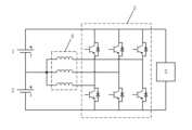
도 1은 본 개시내용의 일 실시예에 따른 배터리 자가 가열 디바이스의 구조 블록도이다. 도 1에 도시된 바와 같이, 디바이스는 브리지 암 컨버터(bridge arm converter)(3), 에너지 저장 엘리먼트(5), 인덕터(4) 및 제어기(미도시)를 포함한다. 브리지 암 컨버터(3)의 제1 버스 단자는 제1 파워 배터리(1)의 양극에 연결되고, 브리지 암 컨버터(3)의 제2 버스 단자는 제2 파워 배터리(2)의 음극에 연결된다. 인덕터(4)의 제1 단부는 브리지 암 컨버터(3)의 중간점에 연결되고, 인덕터(4)의 제2 단부는 제1 파워 배터리(1)의 음극과 제2 파워 배터리(2)의 양극에 연결된다. 에너지 저장 엘리먼트(5)는 제1 파워 배터리(1)의 양극과 제2 파워 배터리(2)의 음극 사이에 병렬로 연결되고, 에너지 저장 엘리먼트(5)의 제1 단부는 브리지 암 컨버터(3)의 제1 버스 단자에 연결되고, 에너지 저장 엘리먼트(5)의 제2 단부는 브리지 암 컨버터(3)의 제2 버스 단자에 연결된다. 제어기는 미리 설정된 상태에서 브리지 암 컨버터(3)의 연결 및 연결 해제를 제어하여 제1 파워 배터리(1)와 제2 파워 배터리(2)가 인덕터(4)에 의해 각각 충전/방전되게 하고, 에너지 저장 엘리먼트(5)와 환류 회로를 각각 형성하여 제1 파워 배터리(1)와 제2 파워 배터리(2)의 지속적인 가열을 구현하도록 구성된다.FIG. 1 is a structural block diagram of a battery self-heating device according to one embodiment of the present disclosure. As illustrated in FIG. 1, the device includes a bridge arm converter (3), an energy storage element (5), an inductor (4), and a controller (not shown). A first bus terminal of the bridge arm converter (3) is connected to a positive pole of a first power battery (1), and a second bus terminal of the bridge arm converter (3) is connected to a negative pole of a second power battery (2). A first end of the inductor (4) is connected to a midpoint of the bridge arm converter (3), and a second end of the inductor (4) is connected to a negative pole of the first power battery (1) and a positive pole of the second power battery (2). An energy storage element (5) is connected in parallel between a positive electrode of a first power battery (1) and a negative electrode of a second power battery (2), a first end of the energy storage element (5) is connected to a first bus terminal of a bridge arm converter (3), and a second end of the energy storage element (5) is connected to a second bus terminal of the bridge arm converter (3). A controller controls connection and disconnection of the bridge arm converter (3) in a preset state so that the first power battery (1) and the second power battery (2) are charged/discharged by the inductor (4), respectively, and forms a reflux circuit with the energy storage element (5), respectively, to implement continuous heating of the first power battery (1) and the second power battery (2).
제1 파워 배터리(1) 및 제2 파워 배터리(2)는 동일한 차량 내의 파워 배터리일 수 있다. 제1 파워 배터리(1) 및 제2 파워 배터리(2)는 별도로 배치된 2개의 파워 배터리일 수 있고, 차량 내에서 원래의 파워 배터리를 분할하여 획득된 파워 배터리의 2개의 부분일 수 있다. 예를 들어, 차량 내 파워 배터리를 제1 파워 배터리(1) 및 제2 파워 배터리(2)로 분할하기 위해 차량 내 원래의 파워 배터리의 중간점이 리드 아웃(lead out)될 수 있다. 브리지 암 컨버터(3)는 차량 내 모터 제어기 내 브리지 암 컨버터(3)일 수 있다. 인덕터(4)는 차량 내 모터 제어기에 의해 제어되는 모터 내 인덕터(4)일 수 있다. 제어기는 임의의 형태의 제어기일 수 있으며, 이는 별도로 배열된 제어기일 수 있거나, 차량 제어 유닛(VCU) 등에 통합된 제어 모듈일 수 있다.The first power battery (1) and the second power battery (2) may be power batteries within the same vehicle. The first power battery (1) and the second power battery (2) may be two separately arranged power batteries, or may be two parts of a power battery obtained by dividing an original power battery within the vehicle. For example, a midpoint of an original power battery within the vehicle may be lead out to divide the power battery within the vehicle into the first power battery (1) and the second power battery (2). The bridge arm converter (3) may be a bridge arm converter (3) within a motor controller within the vehicle. The inductor (4) may be an inductor (4) within a motor controlled by a motor controller within the vehicle. The controller may be any type of controller, which may be a separately arranged controller, or a control module integrated into a vehicle control unit (VCU), etc.
미리 설정된 상태는 제1 파워 배터리(1) 및 제2 파워 배터리(2)가 가열될 필요가 있는 상태로서, 예를 들어 제1 파워 배터리(1) 및 제2 파워 배터리(2)의 전기량이 미리 설정된 전기량 임계치보다 낮거나, 제1 파워 배터리(1) 및 제2 파워 배터리(2)의 온도가 미리 설정된 온도 임계치보다 낮은 상태일 수 있다.The preset state is a state in which the first power battery (1) and the second power battery (2) need to be heated, for example, the electric quantity of the first power battery (1) and the second power battery (2) may be lower than a preset electric quantity threshold, or the temperature of the first power battery (1) and the second power battery (2) may be lower than a preset temperature threshold.
제어기는 미리 설정된 상태에서 브리지 암 컨버터(3)의 연결 및 연결 해제를 제어하여, 인덕터(4)에 의해 제1 파워 배터리(1) 및 제2 파워 배터리(2) 각각에 발진 전류가 발생되고, 인덕터(4)에 의해 제1 파워 배터리(1) 및 제2 파워 배터리(2)가 각각 충전/방전되어 제1 파워 배터리(1) 및 제2 파워 배터리(2)의 가열이 구현된다. 따라서, 별도의 가열 장비 없이도 파워 배터리의 자가 가열이 구현될 수 있으며, 제1 파워 배터리(1)와 제2 파워 배터리(2)가 각각 인덕터(4)에 의해 발진 전류를 생성하여 충전 및 방전할 수 있는데, 즉, 제1 파워 배터리(1)가 방전되면 제2 파워 배터리(2)가 충전되고, 제2 파워 배터리(2)가 방전되면 제1 파워 배터리(1)가 충전된다. 따라서, 제1 파워 배터리(1) 및 제2 파워 배터리(2)의 전체 전압이 비교적 안정적이고 변화되지 않은 것을 보장할 수 있어서, 배터리 자가 가열 과정에서의 배터리 리플을 줄일 수 있고, 차량 내에서의 전기적 안전성을 보장할 수 있다.The controller controls the connection and disconnection of the bridge arm converter (3) in a preset state, so that an oscillating current is generated in each of the first power battery (1) and the second power battery (2) by the inductor (4), and the first power battery (1) and the second power battery (2) are respectively charged/discharged by the inductor (4), thereby implementing heating of the first power battery (1) and the second power battery (2). Therefore, self-heating of the power battery can be implemented without a separate heating device, and the first power battery (1) and the second power battery (2) can be charged and discharged by respectively generating an oscillating current by the inductor (4), that is, when the first power battery (1) is discharged, the second power battery (2) is charged, and when the second power battery (2) is discharged, the first power battery (1) is charged. Therefore, it is possible to ensure that the total voltage of the first power battery (1) and the second power battery (2) is relatively stable and unchanged, thereby reducing battery ripple during the battery self-heating process and ensuring electrical safety within the vehicle.
추가하여, 에너지 저장 엘리먼트(5)가 제1 파워 배터리(1)와 제2 파워 배터리(2) 사이에 병렬로 연결되어, 제1 파워 배터리(1)가 충전/방전되고 제2 파워 배터리(2)가 충전/방전되는 임의의 상태에서 제1 파워 배터리(1)와 제2 파워 배터리(2)의 전류가 차단되지 않고, 제1 파워 배터리(1)와 제2 파워 배터리(2)의 가열이 지속되므로, 배터리의 자가 가열 효율을 추가로 보장할 수 있으며, 배터리 내 차단된 전류에 따른 고조파 위험을 방지할 수 있다.In addition, an energy storage element (5) is connected in parallel between the first power battery (1) and the second power battery (2), so that in any state where the first power battery (1) is charged/discharged and the second power battery (2) is charged/discharged, the current of the first power battery (1) and the second power battery (2) is not interrupted and the heating of the first power battery (1) and the second power battery (2) continues, so that the self-heating efficiency of the battery can be additionally ensured and the risk of harmonics due to the interrupted current in the battery can be prevented.
전술한 과제 해결책을 통하여, 에너지 저장 엘리먼트를 이용하여 환류 용량을 제공하는 배터리 자기 가열 디바이스가 제공된다. 2개의 파워 배터리가 제공되고, 2개의 파워 배터리 각각과 인덕터 사이에 발진 전류를 발생시키는 환류를 위해 에너지 저장 엘리먼트가 제공되어, 저비용 고효율의 배터리 자가 가열을 구현할 수 있으며, 2개의 파워 배터리 전체의 전압의 안정성 및 배터리 내의 전류의 지속적인 흐름을 보장할 수 있어 자가 가열 과정에서 배터리의 안전성을 보장할 수 있다.Through the above-described problem solution, a battery self-heating device is provided which provides a reflux capacity by using an energy storage element. Two power batteries are provided, and an energy storage element is provided for reflux that generates an oscillating current between each of the two power batteries and an inductor, so that low-cost and high-efficiency battery self-heating can be implemented, and the stability of the voltage of the entire two power batteries and the continuous flow of current within the battery can be guaranteed, so that the safety of the battery can be guaranteed during the self-heating process.
가능한 실시예에서, 브리지 암 컨버터(3)는 브리지 암의 하나의 상(phase) 또는 브리지 암의 다수의 상을 포함할 수 있다. 본 개시내용에서, 브리지 암 컨버터(3)의 상의 개수는 한정되지 않으며, 차량의 모터 제어기에 실제 적용되는 브리지 암 컨버터에 따라 구체적으로 결정될 수 있다. 하나 이상의 인덕터(4)가 있을 수 있으며, 이는 브리지 암 컨버터(3)의 상의 개수에 따라 구체적으로 결정될 수 있다. 예를 들어, 브리지 암 컨버터(3)는 3상의 브리지 암을 포함할 수 있고, 구체적으로 도 2에 도시된 바와 같이, 3개의 인덕터(4)가 있을 수 있고, 도 2는 3상의 브리지 암 및 3상의 브리지 암에 대응하는 3개의 인덕터(4)를 포함하는 컨버터를 포함하는 배터리 자가 가열 디바이스의 개략도를 도시한다. 인덕터들(4)의 제1 단부는 3상의 브리지 암의 중간점들에 각각 연결된다. 인덕터(4)의 제2 단부는 서로 연결된 후 제1 파워 배터리(1)의 음극과 제2 파워 배터리(2)의 양극에 연결된다.In a possible embodiment, the bridge arm converter (3) may include one phase of the bridge arm or multiple phases of the bridge arm. In the present disclosure, the number of phases of the bridge arm converter (3) is not limited and may be specifically determined according to the bridge arm converter actually applied to the motor controller of the vehicle. There may be one or more inductors (4), which may be specifically determined according to the number of phases of the bridge arm converter (3). For example, the bridge arm converter (3) may include three-phase bridge arms, and specifically, as shown in FIG. 2, there may be three inductors (4), which is a schematic diagram of a battery self-heating device including a converter including three bridge arms of three phases and three inductors (4) corresponding to the three-phase bridge arms. First ends of the inductors (4) are respectively connected to midpoints of the three-phase bridge arms. The second end of the inductor (4) is connected to the negative pole of the first power battery (1) and the positive pole of the second power battery (2) after being connected to each other.
모터를 포함하는 공통 회로에서, 언제라도, 모터의 중성점(neutral point)으로 진입하는 총 전류가 모터의 중성점으로부터 유출되는 총 전류와 동일한 것을 보장하기 위해, 모터의 인덕터들(4)을 통해 흐르는 전류들은 상이한 방향들 예를 들어, 하나의 페이즈 인(phase in) 및 하나의 페이즈 아웃(phase out), 또는 하나의 페이즈 인 및 2개의 페이즈 아웃, 또는 하나의 페이즈 아웃 및 2개의 페이즈 인을 갖는다. 따라서, 종래의 모터에 흐르는 최대 전류는 1상 인덕터(4)의 제한된 전류만이 될 수 있다. 그러나, 도 2에 도시된 본 발명에 따른 배터리 자가 가열 디바이스의 개략도에서, 브리지 암 컨버터(3)가 3상의 브리지 암과, 3상의 브리지 암의 중간점에 각각 연결된 3개의 인덕터(4)를 포함하는 경우, 인덕터(4)는 제1 파워 배터리(1)의 음극과 제2 파워 배터리(2)의 양극에 연결된 인덕터(4)의 제2 단부를 통해 리드 아웃될 수 있으므로, 인덕터(4)의 3상 전류는 동일한 방향일 수 있다. 따라서, 인덕터(4)에 흐를 수 있는 전류의 크기가 상당히 증가시키고, 인덕터(4)가 위치된 모터의 최대 전류 흐름 용량이 충분히 제공될 수 있다. 전류가 높을수록 제1 파워 배터리(1) 및 제2 파워 배터리(2)에서 발생하는 열이 많아지므로, 본 실시예에 의해 달성되는 배터리 자가 가열 효율이 더욱 향상될 수 있다.In a common circuit including a motor, in order to ensure that at any time the total current entering the neutral point of the motor is equal to the total current flowing out of the neutral point of the motor, the currents flowing through the inductors (4) of the motor have different directions, for example, one phase in and one phase out, or one phase in and two phases out, or one phase out and two phases in. Therefore, the maximum current flowing in a conventional motor can only be the limited current of the one-phase inductor (4). However, in the schematic diagram of the battery self-heating device according to the present invention illustrated in FIG. 2, if the bridge arm converter (3) includes three bridge arms of the three phases and three inductors (4) each connected to the midpoints of the three-phase bridge arms, the inductors (4) can be led out through the second ends of the inductors (4) connected to the negative pole of the first power battery (1) and the positive pole of the second power battery (2), so that the three-phase currents of the inductors (4) can be in the same direction. Accordingly, the size of the current that can flow in the inductors (4) is significantly increased, and the maximum current flow capacity of the motor in which the inductors (4) are positioned can be sufficiently provided. The higher the current, the more heat is generated in the first power battery (1) and the second power battery (2), so that the battery self-heating efficiency achieved by the present embodiment can be further improved.
또한, 도 2에 도시된 바와 같이, 브리지 암 컨버터(3)가 3상의 브리지 암과, 3상의 브리지 암의 중간점에 각각 연결된 3개의 인덕터(4)를 포함하는 배터리 자가 가열 디바이스에서, 3개의 인덕터(4)의 전류가 동일하면, 3개의 인덕터(4)의 전류의 크기는 동일하다. 인덕터(4)가 위치된 모터에서 합성되는 실시간 전자기력은 0이므로, 제로 토크 출력을 구현할 수 있으며, 추가적인 토크 제어 없이 자가 가열 과정에서 모터가 정지 상태를 유지하는 것을 보장할 수 있다.In addition, as illustrated in FIG. 2, in a battery self-heating device in which a bridge arm converter (3) includes three bridge arms of three phases and three inductors (4) each connected to a midpoint of the bridge arms of the three phases, if the currents of the three inductors (4) are the same, the magnitudes of the currents of the three inductors (4) are the same. Since the real-time electromagnetic force synthesized in the motor where the inductors (4) are positioned is 0, a zero torque output can be implemented, and it is ensured that the motor remains stationary during the self-heating process without additional torque control.
가능한 실시예에서, 도 3에 도시된 바와 같이, 에너지 저장 엘리먼트(5)는 커패시터일 수 있다.In a possible embodiment, as illustrated in FIG. 3, the energy storage element (5) may be a capacitor.
가능한 실시예에서, 제1 파워 배터리(1) 및 제2 파워 배터리(2) 중 하나가 인덕터(4)에 의해 충전/방전될 때(도 4, 도 6, 도 8 및 도 10에 도시된 바와 같이), 제1 파워 배터리(1) 및 제2 파워 배터리(2) 중 다른 하나는 에너지 저장 엘리먼트(5)와 환류 회로를 형성한다(도 5, 도 7, 도 9 및 도 11에 도시된 바와 같이, 당업자는 환류 회로가 다른 엘리먼트들, 예를 들어 도 5의 인덕터(4) 및 도 7의 다른 파워 배터리를 더 포함할 수 있다는 것이 이해될 것이고, 이는 여기서 반복되지 않을 것이다).In a possible embodiment, when one of the first power battery (1) and the second power battery (2) is charged/discharged by the inductor (4) (as shown in FIGS. 4, 6, 8 and 10), the other one of the first power battery (1) and the second power battery (2) forms a freewheeling circuit with the energy storage element (5) (as shown in FIGS. 5, 7, 9 and 11; it will be appreciated by those skilled in the art that the freewheeling circuit may further include other elements, for example the inductor (4) of FIG. 5 and the other power battery of FIG. 7, which will not be repeated herein).
또한, 인덕터(4)에 의해 제1 파워 배터리(1) 및 제2 파워 배터리(2) 중 하나가 충전/방전될 때의 전류 흐름 방향은 제1 방향(도 4, 도 6, 도 8 및 도 10에 도시됨)이고, 제1 파워 배터리(1) 및 제2 파워 배터리(2) 중 다른 하나의 환류 전류 흐름 방향은 제2 방향(도 5, 도 7, 도 9 및 도 11에 도시됨)이며, 제1 방향은 제2 방향과 반대이다.In addition, when one of the first power battery (1) and the second power battery (2) is charged/discharged by the inductor (4), the direction of current flow is the first direction (as shown in FIGS. 4, 6, 8, and 10), and the direction of freewheeling current flow of the other one of the first power battery (1) and the second power battery (2) is the second direction (as shown in FIGS. 5, 7, 9, and 11), and the first direction is opposite to the second direction.
가능한 실시예에서, 제어기는, 미리 설정된 상태에서, 브리지 암 컨버터(3)의 상부 브리지 암 및 하부 브리지 암의 교번하는 연결 및 연결 해제를 제어하여 제1 파워 배터리(1) 및 제2 파워 배터리(2)가 인덕터(4)에 의해 각각 충전/방전될 수 있게 하고, 에너지 저장 엘리먼트(5)와 각각 환류 회로를 형성하여 제1 파워 배터리(1) 및 제2 파워 배터리(2)의 지속적인 가열을 구현하도록 구성된다. 구체적인 교번하는 연결 및 연결 해제 방식은 도 4 내지 도 11에 도시될 수 있다. 도 4 내지 도 11의 다양한 디바이스의 참조 부호는 도시되지 않으며, 도 1 내지 도 3의 다양한 디바이스의 참조 부호를 참조할 수 있다.In a possible embodiment, the controller is configured to control, in a preset state, the alternate connection and disconnection of the upper bridge arm and the lower bridge arm of the bridge arm converter (3) so that the first power battery (1) and the second power battery (2) can be charged/discharged respectively by the inductor (4), and form a reflux circuit with the energy storage element (5), respectively, to implement continuous heating of the first power battery (1) and the second power battery (2). Specific alternate connection and disconnection schemes can be illustrated in FIGS. 4 to 11. Reference symbols of various devices in FIGS. 4 to 11 are not illustrated, and reference symbols of various devices in FIGS. 1 to 3 may be made.
도 4 내지 도 11은 본 개시내용의 일 실시예에 따른 배터리 자가 가열 과정에서 전류 사이클 기간 내 4개의스테이지의 전류 흐름 방향의 각각의 개략도이다.FIGS. 4 to 11 are schematic diagrams of current flow directions of four stages within a current cycle period during a battery self-heating process according to one embodiment of the present disclosure.
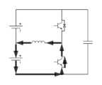
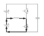
제1 스테이지: 브리지 암 컨버터(3)의 상부 브리지 암이 연결되도록 제어되고, 하부 브리지 암이 분리되도록 제어되고, 제1 파워 배터리(1)가 방전되고, 에너지 저장 엘리먼트(5)가 방전되고, 제2 파워 배터리(2)가 충전되고, 인덕터(4)가 충전된다. 배터리를 자가 가열하기 위한 발진 전류의 흐름 방향은 도 4에 도시되어 있다. 전류는 제1 파워 배터리(1)의 양극으로부터 유출되고, 브리지 암 컨버터(3)의 상부 브리지 암 및 인덕터(4)를 거쳐 다시 제1 파워 배터리(1)의 음극으로 흐른다. 제1 파워 배터리(1)는 인덕터(4)로 방전된다. 환류 전류의 흐름 방향은 도 5에 도시되어 있다. 전류는 에너지 저장 엘리먼트(5)의 양극으로부터 유출되고, 브리지 암 컨버터(3)의 상부 브리지 암, 인덕터(4) 및 제2 파워 배터리(2)를 통해 흘러 에너지 저장 엘리먼트(5)의 음극으로 다시 흐른다. 제2 파워 배터리(2)가 충전된다.Stage 1: The upper bridge arm of the bridge arm converter (3) is controlled to be connected, the lower bridge arm is controlled to be disconnected, the first power battery (1) is discharged, the energy storage element (5) is discharged, the second power battery (2) is charged, and the inductor (4) is charged. The direction of the flow of the oscillation current for self-heating the battery is shown in Fig. 4. The current flows from the positive electrode of the first power battery (1), through the upper bridge arm of the bridge arm converter (3) and the inductor (4), and then flows back to the negative electrode of the first power battery (1). The first power battery (1) is discharged to the inductor (4). The direction of the flow of the freewheeling current is shown in Fig. 5. The current flows from the positive electrode of the energy storage element (5), flows through the upper bridge arm of the bridge arm converter (3), the inductor (4), and the second power battery (2), and then flows back to the negative electrode of the energy storage element (5). The second power battery (2) is charged.
도 4에 도시된 방전 과정과 도 5에 도시된 환류 전류 충전 과정은 동시에 수행된다는 것에 주목해야 한다. 따라서, 제1 스테이지에서, 제1 파워 배터리(1) 및 제2 파워 배터리(2)에 동시에 흐르는 전류가 존재하여, 동시 자가 가열이 구현된다. 더욱이, 제1 파워 배터리(1)와 제2 파워 배터리(2)의 전류 방향은 반대이다. 제1 파워 배터리(1)와 제2 파워 배터리(2)의 단자 전압의 변화는 서로 상쇄될 수 있다. 배터리 팩의 전체적인 단자 전압 변동이 작고, 이는 배터리 팩의 리플을 줄일 수 있다.It should be noted that the discharging process illustrated in Fig. 4 and the reflux current charging process illustrated in Fig. 5 are performed simultaneously. Therefore, in the first stage, currents flowing simultaneously in the first power battery (1) and the second power battery (2) exist, so that simultaneous self-heating is realized. Furthermore, the current directions of the first power battery (1) and the second power battery (2) are opposite. The changes in the terminal voltages of the first power battery (1) and the second power battery (2) can be offset from each other. The overall terminal voltage fluctuation of the battery pack is small, which can reduce the ripple of the battery pack.
제2 스테이지: 브리지 암 컨버터(3)의 상부 브리지 암이 연결 해제되도록 제어되고, 하부 브리지 암이 연결되도록 제어되고, 제1 파워 배터리(1)가 방전되고, 인덕터(4)가 방전되고, 제2 파워 배터리(2)가 충전되고, 에너지 저장 엘리먼트(5)가 충전된다. 배터리를 자가 가열하기 위한 발진 전류의 흐름 방향은 도 6에 도시되어 있다. 전류는 인덕터(4)에서 제2 파워 배터리(2)의 양극으로 유출되고, 제2 파워 배터리(2)의 음극으로부터 유출되어 브리지 암 컨버터(3)의 하부 브리지 암을 통해 흘러 인덕터(4)로 다시 흐른다. 인덕터(4)에 의해 제2 파워 배터리(2)가 충전된다. 환류 전류의 흐름 방향은 도 7에 도시되어 있다. 제1 파워 배터리(1)는 제2 파워 배터리(2)와 직렬로 연결된다. 전류는 제1 파워 배터리(1)의 양극으로부터 유출되어 에너지 저장 엘리먼트(5)를 통해 흐르고, 다시 제2 배터리 전력(2)의 음극으로 흐른다. 제1 파워 배터리(1)와 제2 파워 배터리(2)는 함께 에너지 저장 엘리먼트(5)로 방전된다.Second stage: The upper bridge arm of the bridge arm converter (3) is controlled to be disconnected, the lower bridge arm is controlled to be connected, the first power battery (1) is discharged, the inductor (4) is discharged, the second power battery (2) is charged, and the energy storage element (5) is charged. The direction of the flow of the oscillation current for self-heating the battery is shown in Fig. 6. The current flows from the inductor (4) to the positive electrode of the second power battery (2), flows from the negative electrode of the second power battery (2), flows through the lower bridge arm of the bridge arm converter (3), and flows back to the inductor (4). The second power battery (2) is charged by the inductor (4). The direction of the flow of the freewheeling current is shown in Fig. 7. The first power battery (1) is connected in series with the second power battery (2). Current flows from the positive electrode of the first power battery (1), through the energy storage element (5), and then to the negative electrode of the second battery power (2). The first power battery (1) and the second power battery (2) are discharged together to the energy storage element (5).
도 6에 도시된 충전 과정과 도 7에 도시된 환류 전류 방전 과정은 동시에 수행된다는 것에 주목해야 한다. 따라서, 제1 스테이지에서, 제1 파워 배터리(1) 및 제2 파워 배터리(2)에 동시에 흐르는 전류가 존재하여, 동시 자가 가열이 구현된다. 더욱이, 제1 파워 배터리(1)와 제2 파워 배터리(2)의 전류 방향은 반대이다. 제1 파워 배터리(1)와 제2 파워 배터리(2)의 단자 전압의 변화는 서로 상쇄될 수 있다. 배터리 팩의 전체적인 단자 전압 변동이 작아 배터리 팩의 리플을 줄일 수 있다.It should be noted that the charging process illustrated in Fig. 6 and the reflux current discharging process illustrated in Fig. 7 are performed simultaneously. Therefore, in the first stage, currents flowing simultaneously in the first power battery (1) and the second power battery (2) exist, so that simultaneous self-heating is realized. Furthermore, the current directions of the first power battery (1) and the second power battery (2) are opposite. The changes in the terminal voltages of the first power battery (1) and the second power battery (2) can be offset from each other. Since the overall terminal voltage fluctuation of the battery pack is small, the ripple of the battery pack can be reduced.
제3 스테이지: 브리지 암 컨버터(3)의 상부 브리지 암은 연결 해제된 상태로 유지되고, 하부 브리지 암은 연결된다. 제1 파워 배터리(1)는 충전되고, 인덕터(4)는 충전되고, 제2 파워 배터리(2)는 방전되고, 에너지 저장 엘리먼트(5)는 방전된다. 배터리를 자가 가열하기 위한 발진 전류의 흐름 방향이 도 8에 도시되어 있다. 전류는 제2 파워 배터리(2)의 양극으로부터 유출되어, 인덕터(4) 및 브리지 암 컨버터(3)의 하부 브리지 암을 통해 흐르고, 다시 제2 파워 배터리(2)로 흐른다. 제2 파워 배터리(2)는 인덕터(4)로 방전된다. 환류 전류의 흐름 방향은 도 9에 도시되어 있다. 전류는 에너지 저장 엘리먼트(5)의 양극으로부터 유출되어, 제1 파워 배터리(1), 인덕터(4) 및 브리지 암 컨버터(3)의 하부 브리지 암을 통해 흐르고, 다시 에너지 저장 엘리먼트(5)의 음극으로 흐른다. 제1 파워 배터리(1)가 충전된다.Stage 3: The upper bridge arm of the bridge arm converter (3) is kept disconnected, and the lower bridge arm is connected. The first power battery (1) is charged, the inductor (4) is charged, the second power battery (2) is discharged, and the energy storage element (5) is discharged. The direction of flow of the oscillation current for self-heating the battery is illustrated in Fig. 8. The current flows from the positive electrode of the second power battery (2), flows through the inductor (4) and the lower bridge arm of the bridge arm converter (3), and flows back to the second power battery (2). The second power battery (2) is discharged to the inductor (4). The direction of flow of the freewheeling current is illustrated in Fig. 9. The current flows from the positive electrode of the energy storage element (5), flows through the first power battery (1), the inductor (4), and the lower bridge arm of the bridge arm converter (3), and flows back to the negative electrode of the energy storage element (5). The first power battery (1) is charged.
도 8에 도시된 방전 과정과 도 9에 도시된 환류 전류 충전 과정은 동시에 수행된다는 것에 주목해야 한다. 따라서, 제1 스테이지에서, 제1 파워 배터리(1) 및 제2 파워 배터리(2)에 동시에 흐르는 전류가 존재하여, 동시 자가 가열이 구현된다. 더욱이, 제1 파워 배터리(1)와 제2 파워 배터리(2)의 전류 방향은 반대이다. 제1 파워 배터리(1)와 제2 파워 배터리(2)의 단자 전압의 변화는 서로 상쇄될 수 있다. 배터리 팩의 전체적인 단자 전압 변동이 작아 배터리 팩의 리플을 줄일 수 있다.It should be noted that the discharging process illustrated in Fig. 8 and the reflux current charging process illustrated in Fig. 9 are performed simultaneously. Therefore, in the first stage, currents flowing simultaneously in the first power battery (1) and the second power battery (2) exist, so that simultaneous self-heating is implemented. Furthermore, the current directions of the first power battery (1) and the second power battery (2) are opposite. The changes in the terminal voltages of the first power battery (1) and the second power battery (2) can be offset from each other. The overall terminal voltage fluctuation of the battery pack is small, so that the ripple of the battery pack can be reduced.
제4 스테이지: 브리지 암 컨버터(3)의 상부 브리지 암은 연결되도록 제어되고, 하부 브리지 암은 연결 해제되도록 제어된다. 제1 파워 배터리(1)는 충전되고, 에너지 저장 엘리먼트(5)는 충전되며, 제2 파워 배터리(2)는 방전되고, 인덕터(4)는 방전된다. 배터리를 자가 가열하기 위한 발진 전류의 흐름 방향이 도 10에 도시되어 있다. 전류는 인덕터(4)로부터 유출되고, 브리지 암 컨버터(3)의 상부 브리지 암을 통해 흐르고, 제1 파워 배터리(1)의 양극으로 흐르고, 제1 파워 배터리(1)의 음극으로부터 유출되어 다시 인덕터(4)로 흐른다. 인덕터(4)에 의해 제1 파워 배터리(1)가 충전된다. 환류 전류의 흐름 방향은 도 11에 도시되어 있다. 제1 파워 배터리(1)는 제2 파워 배터리(2)와 직렬로 연결된다. 전류는 제1 파워 배터리(1)의 양극으로부터 유출되어 에너지 저장 엘리먼트(5)를 통해 흐르고, 다시 제2 배터리 전력(2)의 음극으로 흐른다. 제1 파워 배터리(1)와 제2 파워 배터리(2)는 함께 에너지 저장 엘리먼트(5)로 방전된다.Stage 4: The upper bridge arm of the bridge arm converter (3) is controlled to be connected, and the lower bridge arm is controlled to be disconnected. The first power battery (1) is charged, the energy storage element (5) is charged, the second power battery (2) is discharged, and the inductor (4) is discharged. The direction of flow of the oscillation current for self-heating the battery is shown in Fig. 10. The current flows from the inductor (4), flows through the upper bridge arm of the bridge arm converter (3), flows to the positive electrode of the first power battery (1), flows from the negative electrode of the first power battery (1), and flows back to the inductor (4). The first power battery (1) is charged by the inductor (4). The direction of flow of the freewheeling current is shown in Fig. 11. The first power battery (1) is connected in series with the second power battery (2). Current flows from the positive electrode of the first power battery (1), through the energy storage element (5), and then to the negative electrode of the second battery power (2). The first power battery (1) and the second power battery (2) are discharged together to the energy storage element (5).
도 10에 도시된 충전 과정과 도 11에 도시된 환류 전류 방전 과정은 동시에 수행된다는 것에 주목해야 한다. 따라서, 제1 스테이지는 제1 파워 배터리(1) 및 제2 파워 배터리(2)에 동시에 흐르는 전류가 존재하여, 동시 자가 가열이 구현된다. 더욱이, 제1 파워 배터리(1)와 제2 파워 배터리(2)의 전류 방향은 반대이다. 제1 파워 배터리(1)와 제2 파워 배터리(2)의 단자 전압의 변화는 서로 상쇄될 수 있다. 배터리 팩의 전체적인 단자 전압 변동이 작아 배터리 팩의 리플을 줄일 수 있다.It should be noted that the charging process illustrated in Fig. 10 and the reflux current discharging process illustrated in Fig. 11 are performed simultaneously. Therefore, in the first stage, there is a current that flows simultaneously to the first power battery (1) and the second power battery (2), so that simultaneous self-heating is implemented. Furthermore, the current directions of the first power battery (1) and the second power battery (2) are opposite. The changes in the terminal voltages of the first power battery (1) and the second power battery (2) can be offset from each other. Since the overall terminal voltage fluctuation of the battery pack is small, the ripple of the battery pack can be reduced.
가능한 실시예에서, 제어기는 미리 설정된 상태에서, 미리 설정된 듀티 사이클 할당 설정에 따라 브리지 암 컨버터(3)의 상부 브리지 암과 하부 브리지 암의 교번하는 연결 및 연결 해제를 제어하도록 구성된다. 따라서, 제어기는 미리 설정된 듀티 사이클 할당 설정에 따라 상부 브리지 암과 하부 브리지 암의 연결 및 연결 해제된 상태를 스위칭할 시간을 정확하게 결정하여 도 4 및 도 5에 도시된 스테이지로부터 도 6 및 도 7에 도시된 스테이지로 스위칭하고, 도 8 및 도 9에 도시된 스테이지로부터 도 10 및 도 11에 도시된 스테이지로 스위칭하여 정확하게 제어할 수 있다.In a possible embodiment, the controller is configured to control the alternate connection and disconnection of the upper bridge arm and the lower bridge arm of the bridge arm converter (3) according to the preset duty cycle allocation settings in the preset state. Accordingly, the controller can accurately determine the time for switching the connected and disconnected states of the upper bridge arm and the lower bridge arm according to the preset duty cycle allocation settings, thereby accurately controlling switching from the stages illustrated in FIGS. 4 and 5 to the stages illustrated in FIGS. 6 and 7, and switching from the stages illustrated in FIGS. 8 and 9 to the stages illustrated in FIGS. 10 and 11.
구체적으로, 미리 설정된 듀티 사이클 할당 설정에 따라 브리지 암 컨버터(3)의 상부 브리지 암과 하부 브리지 암이 서로 교번하는 연결 및 연결 해제되도록 제어되는 일 예로, 제어기는, 미리 설정된 상태에서, 브리지 암 컨버터(3)의 상부 브리지 암이 연결된 상태이고, 브리지 암 컨버터(3)의 하부 브리지 암이 연결 해제된 상태이고, 브리지 암 컨버터(3)의 상부 브리지 암이 연결된 상태에 있는 지속 기간이 미리 설정된 듀티 사이클 할당 설정에서 미리 설정된 제1 지속 기간에 도달할 때, 브리지 암 컨버터(3)의 상부 브리지 암은 연결 해제되고, 브리지 암 컨버터(3)의 하부 브리지 암은 연결된 상태가 되도록 제어될 수 있다. 예를 들어, 도 4 및 도 5에 도시된 스테이지는 도 6 및 도 7에 도시된 스테이지로 스위칭된다. 브리지 암 컨버터(3)의 하부 브리지 암이 연결된 상태이고, 브리지 암 컨버터(3)의 상부 브리지 암이 연결 해제된 상태이고, 브리지 암 컨버터(3)의 하부 브리지 암이 연결된 상태인 지속기간이 미리 설정된 듀티 사이클 할당 설정에서 미리 설정된 제2 지속 기간에 도달할 때, 브리지 암 컨버터(3)의 상부 브리지 암은 연결되도록 제어되고, 브리지 암 컨버터(3)의 하부 브리지 암은 연결 해제되도록 제어된다. 예를 들어, 도 8 및 도 9에 도시된 스테이지는 도 10 및 도 11에 도시된 스테이지로 스위칭된다.Specifically, as an example in which the upper bridge arm and the lower bridge arm of the bridge arm converter (3) are controlled to be alternately connected and disconnected according to the preset duty cycle allocation settings, the controller can be controlled such that, in a preset state, the upper bridge arm of the bridge arm converter (3) is in a connected state, the lower bridge arm of the bridge arm converter (3) is in a disconnected state, and the duration during which the upper bridge arm of the bridge arm converter (3) is in a connected state reaches a preset first duration in the preset duty cycle allocation settings, the upper bridge arm of the bridge arm converter (3) is disconnected and the lower bridge arm of the bridge arm converter (3) is in a connected state. For example, the stages illustrated in FIGS. 4 and 5 are switched to the stages illustrated in FIGS. 6 and 7. When the duration during which the lower bridge arm of the bridge arm converter (3) is connected, the upper bridge arm of the bridge arm converter (3) is disconnected, and the lower bridge arm of the bridge arm converter (3) is connected reaches a preset second duration in the preset duty cycle allocation settings, the upper bridge arm of the bridge arm converter (3) is controlled to be connected, and the lower bridge arm of the bridge arm converter (3) is controlled to be disconnected. For example, the stages illustrated in FIGS. 8 and 9 are switched to the stages illustrated in FIGS. 10 and 11.
미리 설정된 듀티 사이클 할당 설정에서 제1 미리 설정된 지속 기간과 제2 미리 설정된 지속 기간은 모두 경험적 데이터에 의해 결정될 수 있거나, 실험 데이터에 따라 미리 캘리브레이션될 수 있거나, 공식에 따라 결정될 수 있다. 공식은 다양한 임계치들과 환경 정보 사이의 대응을 특성화할 수 있다. 환경 정보가 변경되는 경우, 대응하여 다양한 임계치들이 변경될 수 있다. 환경 정보는 예를 들어, 배터리 사용 지속시간, SOC(State of Charge) 정보, 배터리 온도, 주변 온도를 포함할 수 있다.In the preset duty cycle allocation setting, both the first preset duration and the second preset duration can be determined by empirical data, can be pre-calibrated according to experimental data, or can be determined according to a formula. The formula can characterize the correspondence between various thresholds and environmental information. When the environmental information changes, the various thresholds can be changed correspondingly. The environmental information can include, for example, battery usage duration, SOC (State of Charge) information, battery temperature, and ambient temperature.
추가하여, 브리지 암 컨버터(3)의 상부 브리지 암이 연결된 상태에 있을 때, 브리지 암 컨버터(3)의 상부 브리지 암의 연결 시간에 따라 인덕터(4)는 제1 파워 배터리(1)로 에너지를 방출하는 상태로부터 제1 파워 배터리(1) 및 에너지 저장 엘리먼트(5)의 에너지를 수신하는 상태로 스위칭되고, 에너지 저장 엘리먼트(5)는 제1 파워 배터리(1) 및 제2 파워 배터리(2)의 에너지를 수신하는 상태로부터 제2 파워 배터리(2) 및 인덕터(4)로 에너지를 방출하는 상태로 스위칭된다. 예를 들어, 도 10 및 도 11에 도시된 스테이지가 도 4 및 도 5에 도시된 스테이지로 스위칭된다.In addition, when the upper bridge arm of the bridge arm converter (3) is in a connected state, the inductor (4) is switched from a state of emitting energy to the first power battery (1) to a state of receiving energy from the first power battery (1) and the energy storage element (5) according to the connection time of the upper bridge arm of the bridge arm converter (3), and the energy storage element (5) is switched from a state of receiving energy from the first power battery (1) and the second power battery (2) to a state of emitting energy to the second power battery (2) and the inductor (4). For example, the stages illustrated in FIGS. 10 and 11 are switched to the stages illustrated in FIGS. 4 and 5.
브리지 암 컨버터(3)의 하부 브리지 암이 연결된 상태에 있을 때, 브리지 암 컨버터(3)의 하부 브리지 암의 연결 시간에 따라 인덕터(4)는 제2 파워 배터리(2)로 에너지를 방출하는 상태로부터 제2 파워 배터리(2) 및 에너지 저장 엘리먼트(5)의 에너지를 수신하는 상태로 스위칭되고, 에너지 저장 엘리먼트(5)는 제1 파워 배터리(1) 및 제2 파워 배터리(2)의 에너지를 수신하는 상태로부터 제1 파워 배터리(1) 및 인덕터(4)로 에너지를 방출하는 상태로 스위칭된다. 예를 들어, 도 6 및 도 7에 도시된 스테이지가 도 8 및 도 9에 도시된 스테이지로 스위칭된다.When the lower bridge arm of the bridge arm converter (3) is in a connected state, the inductor (4) is switched from a state of emitting energy to the second power battery (2) to a state of receiving energy from the second power battery (2) and the energy storage element (5) according to the connection time of the lower bridge arm of the bridge arm converter (3), and the energy storage element (5) is switched from a state of receiving energy from the first power battery (1) and the second power battery (2) to a state of emitting energy to the first power battery (1) and the inductor (4). For example, the stages illustrated in FIGS. 6 and 7 are switched to the stages illustrated in FIGS. 8 and 9.
추가하여, 환류 전류의 지속적인 흐름을 보장하기 위해, 인덕터(4)가 제1 파워 배터리(1) 및 에너지 저장 엘리먼트(5)의 에너지를 공급받는 제1 지속 기간은 미리 설정된 듀티 사이클 할당 설정이 결정된 경우 인덕터(4)가 제2 파워 배터리(2)로 에너지를 방출하는 제2 지속 기간보다 크다. 예를 들어, 도 4 및 도 5에 도시된 스테이지에서의 지속 기간은 도 6 및 도 7에 도시된 스테이지에서의 지속 기간보다 더 크다. 인덕터(4)가 제2 파워 배터리(2) 및 에너지 저장 엘리먼트(5)의 에너지를 수신하는 제3 지속 기간은 인덕터(4)가 제1 파워 배터리(1)로 에너지를 방출하는 제4 지속 기간보다 크도록 보장된다. 예를 들어, 도 8 및 도 9에 도시된 스테이지에서의 지속 기간은 도 10 및 도 11에 도시된 스테이지에서의 지속 기간보다 크다.In addition, in order to ensure a continuous flow of the freewheeling current, the first duration during which the inductor (4) is supplied with energy from the first power battery (1) and the energy storage element (5) is greater than the second duration during which the inductor (4) discharges energy to the second power battery (2) when a preset duty cycle allocation setting is determined. For example, the durations in the stages illustrated in FIGS. 4 and 5 are greater than the durations in the stages illustrated in FIGS. 6 and 7. The third duration during which the inductor (4) receives energy from the second power battery (2) and the energy storage element (5) is ensured to be greater than the fourth duration during which the inductor (4) discharges energy to the first power battery (1). For example, the durations in the stages illustrated in FIGS. 8 and 9 are greater than the durations in the stages illustrated in FIGS. 10 and 11.
가능한 실시예에 있어서, 제어기는 미리 설정된 상태에서 인덕터(4)의 전류 값 및/또는 인덕터(4)의 양단의 전압 값을 획득하고, 전류 값 및/또는 전압 값에 따라 브리지 암 컨버터(3)의 상부 브리지 암 및 하부 브리지 암의 교번하는 연결 및 연결 해제를 제어하도록 추가로 구성될 수 있다. 전류 값 및/또는 전압 전류의 임계치는 대안적으로 실험 데이터에 따라 결정될 수 있거나, 실험 데이터에 따라 미리 캘리브레이션될 수 있다.In a possible embodiment, the controller may be further configured to obtain a current value of the inductor (4) and/or a voltage value across the ends of the inductor (4) in a preset state, and control alternate connection and disconnection of the upper bridge arm and the lower bridge arm of the bridge arm converter (3) according to the current value and/or the voltage value. The threshold of the current value and/or the voltage current may alternatively be determined according to experimental data, or may be calibrated in advance according to experimental data.
도 12는 본 개시내용의 일 실시예에 따른 배터리 자가 가열 방법의 흐름도이다. 도 12에 도시된 바와 같이, 방법은 단계(101)를 포함할 수 있다.FIG. 12 is a flow chart of a battery self-heating method according to one embodiment of the present disclosure. As illustrated in FIG. 12, the method may include step (101).
단계(101)에서, 미리 설정된 상태에서 브리지 암 컨버터(3)의 연결 및 연결 해제를 제어하여 제1 파워 배터리(1) 및 제2 파워 배터리(2)가 인덕터(4)에 의해 각각 충전/방전되게 하고, 에너지 저장 엘리먼트(5)를 이용하여 환류 회로를 각각 형성하여 제1 파워 배터리(1) 및 제2 파워 배터리(2)의 지속적인 가열을 구현할 수 있다.In step (101), the connection and disconnection of the bridge arm converter (3) are controlled in a preset state so that the first power battery (1) and the second power battery (2) are respectively charged/discharged by the inductor (4), and a reflux circuit is respectively formed using the energy storage element (5) so that continuous heating of the first power battery (1) and the second power battery (2) can be implemented.
브리지 암 컨버터(3)의 제1 버스 단자는 제1 파워 배터리(1)의 양극에 연결되고, 브리지 암 컨버터(3)의 제2 버스 단자는 제2 파워 배터리(2)의 음극에 연결된다. 인덕터(4)의 제1 단부는 브리지 암 컨버터(3)의 중간점에 연결되고, 인덕터(4)의 제2 단부는 제1 파워 배터리(1)의 음극과 제2 파워 배터리(2)의 양극에 연결된다. 에너지 저장 엘리먼트(5)는 제1 파워 배터리(1)의 양극과 제2 파워 배터리(2)의 음극 사이에 병렬로 연결되고, 에너지 저장 엘리먼트(5)의 제1 단부는 브리지 암 컨버터(3)의 제1 버스 단자에 연결되고, 에너지 저장 엘리먼트(5)의 제2 단부는 브리지 암 컨버터(3)의 제2 버스 단자에 연결된다.A first bus terminal of the bridge arm converter (3) is connected to the positive pole of the first power battery (1), and a second bus terminal of the bridge arm converter (3) is connected to the negative pole of the second power battery (2). A first end of an inductor (4) is connected to a midpoint of the bridge arm converter (3), and a second end of the inductor (4) is connected to the negative pole of the first power battery (1) and the positive pole of the second power battery (2). An energy storage element (5) is connected in parallel between the positive pole of the first power battery (1) and the negative pole of the second power battery (2), and a first end of the energy storage element (5) is connected to the first bus terminal of the bridge arm converter (3), and a second end of the energy storage element (5) is connected to the second bus terminal of the bridge arm converter (3).
전술한 과제 해결 수단을 통하여, 에너지 저장 엘리먼트를 이용하여 환류 용량을 제공하는 배터리 자기 가열 디바이스가 제공된다. 2개의 파워 배터리가 제공되고, 2개의 파워 배터리 각각과 인덕터 사이에 발진 전류를 발생시키는 환류를 위해 에너지 저장 엘리먼트가 제공되어, 저비용 고효율의 배터리 자가 가열을 구현하고, 2개의 파워 배터리 전체의 전압의 안정성 및 배터리 내의 전류의 지속적인 흐름이 또한 보장될 수 있어서 자가 가열 과정에서 배터리의 안전성을 보장할 수 있다.Through the above-described problem solving means, a battery self-heating device is provided which provides a reflux capacity by using an energy storage element. Two power batteries are provided, and an energy storage element is provided for reflux that generates an oscillating current between each of the two power batteries and an inductor, thereby realizing low-cost and high-efficiency battery self-heating, and the stability of the voltage of the entire two power batteries and the continuous flow of current within the battery can also be guaranteed, thereby ensuring the safety of the battery during the self-heating process.
가능한 실시예에서, 제1 파워 배터리 및 제2 파워 배터리 중 하나가 인덕터에 의해 충전/방전될 때, 제1 파워 배터리 및 제2 파워 배터리 중 다른 하나는 에너지 저장 엘리먼트와 환류 회로를 형성한다.In a possible embodiment, when one of the first power battery and the second power battery is charged/discharged by the inductor, the other one of the first power battery and the second power battery forms a freewheeling circuit with the energy storage element.
가능한 실시예에서, 제1 파워 배터리 및 제2 파워 배터리 중 하나가 인덕터에 의해 충전/방전될 때의 전류 흐름 방향은 제1 방향이고, 제1 파워 배터리 및 제2 파워 배터리 중 다른 하나의 환류 전류 흐름 방향은 제2 방향이고, 제1 방향은 제2 방향과 반대이다.In a possible embodiment, the direction of current flow when one of the first power battery and the second power battery is charged/discharged by the inductor is a first direction, and the direction of freewheeling current flow of the other one of the first power battery and the second power battery is a second direction, and the first direction is opposite to the second direction.
가능한 실시예에서, 방법은 : 미리 설정된 상태에서, 브리지 암 컨버터(3)의 상부 브리지 암 및 하부 브리지 암의 교번하는 연결 및 연결 해제가 제어되어 제1 파워 배터리(1) 및 제2 파워 배터리(2)가 인덕터(4)에 의해 각각 충전/방전되게 하고, 에너지 저장 엘리먼트(5)와 각각 환류 회로를 형성하여 제1 파워 배터리(1) 및 제2 파워 배터리(2)의 지속적인 가열을 구현하는 단계를 더 포함한다.In a possible embodiment, the method further comprises the step of: controlling, in a preset state, alternate connection and disconnection of the upper bridge arm and the lower bridge arm of the bridge arm converter (3), so that the first power battery (1) and the second power battery (2) are respectively charged/discharged by the inductor (4), and forming a reflux circuit with the energy storage element (5), respectively, to implement continuous heating of the first power battery (1) and the second power battery (2).
가능한 실시예에서, 방법은 : 미리 설정된 상태에서, 브리지 암 컨버터(3)의 상부 브리지 암과 하부 브리지 암의 교번하는 연결 및 연결 해제는 미리 설정된 듀티 사이클 할당 설정에 따라 제어되는 단계를 더 포함한다.In a possible embodiment, the method further comprises the step of: in a preset state, the alternating connection and disconnection of the upper bridge arm and the lower bridge arm of the bridge arm converter (3) are controlled according to preset duty cycle allocation settings.
가능한 실시예에서, 방법은 : 미리 설정된 상태에서, 브리지 암 컨버터(3)의 상부 브리지 암이 연결된 상태에 있고, 브리지 암 컨버터(3)의 하부 브리지 암이 연결 해제된 상태에 있고, 브리지 암 컨버터(3)의 상부 브리지 암이 연결된 상태에 있는 지속 기간이 미리 설정된 듀티 사이클 할당 설정에서 제1 미리 설정된 지속시간에 도달할 때, 브리지 암 컨버터(3)의 상부 브리지 암이 연결 해제되도록 제어되고, 브리지 암 컨버터(3)의 하부 브리지 암이 연결되도록 제어되는 단계를 더 포함한다. 브리지 암 컨버터(3)의 하부 브리지 암이 연결된 상태이고, 브리지 암 컨버터(3)의 상부 브리지 암이 연결 해제된 상태이고, 브리지 암 컨버터(3)의 하부 브리지 암이 연결된 상태에 있는 지속 기간이 미리 설정된 듀티 사이클 할당 설정에서 미리 설정된 제2 지속 기간에 도달할 때, 브리지 암 컨버터(3)의 상부 브리지 암은 연결되도록 제어되고, 브리지 암 컨버터(3)의 하부 브리지 암은 연결 해제되도록 제어된다.In a possible embodiment, the method further comprises: in a preset state, the upper bridge arm of the bridge arm converter (3) is in a connected state, the lower bridge arm of the bridge arm converter (3) is in a disconnected state, and when a duration during which the upper bridge arm of the bridge arm converter (3) is in the connected state reaches a first preset duration in a preset duty cycle allocation setting, the upper bridge arm of the bridge arm converter (3) is controlled to be disconnected and the lower bridge arm of the bridge arm converter (3) is controlled to be connected. When the duration during which the lower bridge arm of the bridge arm converter (3) is in the connected state, the upper bridge arm of the bridge arm converter (3) is in a disconnected state, and the lower bridge arm of the bridge arm converter (3) is in the connected state reaches a second preset duration in a preset duty cycle allocation setting, the upper bridge arm of the bridge arm converter (3) is controlled to be connected and the lower bridge arm of the bridge arm converter (3) is controlled to be disconnected.
가능한 실시예로서, 브리지 암 컨버터(3)의 상부 브리지 암이 연결된 상태에 있을 때, 브리지 암 컨버터(3)의 상부 브리지 암의 연결 시간에 따라 인덕터(4)는 제1 파워 배터리(1)로 에너지를 방출하는 것으로부터 제1 파워 배터리(1) 및 에너지 저장 엘리먼트(5)의 에너지를 수신하는 것으로 스위칭되고, 에너지 저장 엘리먼트(5)는 제1 파워 배터리(1) 및 제2 파워 배터리(2)의 에너지를 수신하는 것으로부터 제2 파워 배터리(2) 및 인덕터(4)로 에너지를 방출하는 것으로 스위칭된다. 브리지 암 컨버터(3)의 하부 브리지 암이 연결된 상태에 있을 때, 브리지 암 컨버터(3)의 하부 브리지 암의 연결 시간에 따라 인덕터(4)는 제2 파워 배터리(2)로 에너지를 방출하는 것으로부터, 제2 파워 배터리(2) 및 에너지 저장 엘리먼트(5)의 에너지를 수신하는 것으로 스위칭되고, 에너지 저장 엘리먼트(5)는 제1 파워 배터리(1) 및 제2 파워 배터리(2)의 에너지를 수신하는 것으로부터 제1 파워 배터리(1) 및 인덕터(4)로 에너지를 방출하는 것으로 스위칭된다.As a possible embodiment, when the upper bridge arm of the bridge arm converter (3) is in a connected state, the inductor (4) is switched from emitting energy to the first power battery (1) to receiving energy from the first power battery (1) and the energy storage element (5) depending on the connection time of the upper bridge arm of the bridge arm converter (3), and the energy storage element (5) is switched from receiving energy from the first power battery (1) and the second power battery (2) to emitting energy to the second power battery (2) and the inductor (4). When the lower bridge arm of the bridge arm converter (3) is in a connected state, the inductor (4) is switched from emitting energy to the second power battery (2) to receiving energy from the second power battery (2) and the energy storage element (5) depending on the connection time of the lower bridge arm of the bridge arm converter (3), and the energy storage element (5) is switched from receiving energy from the first power battery (1) and the second power battery (2) to emitting energy to the first power battery (1) and the inductor (4).
가능한 실시예에서, 인덕터(4)가 제1 파워 배터리(1) 및 에너지 저장 엘리먼트(5)의 에너지를 수신하는 제1 지속 기간은 인덕터(4)가 제2 파워 배터리(2)로 에너지를 방출하는 제2 지속 기간보다 크다. 인덕터(4)가 제2 파워 배터리(2) 및 에너지 저장 엘리먼트(5)의 에너지를 수신하는 제3 기간은 인덕터(4)가 제1 파워 배터리(1)로 에너지를 방출하는 제4 기간보다 크다.In a possible embodiment, the first duration during which the inductor (4) receives energy from the first power battery (1) and the energy storage element (5) is longer than the second duration during which the inductor (4) releases energy to the second power battery (2). The third duration during which the inductor (4) receives energy from the second power battery (2) and the energy storage element (5) is longer than the fourth duration during which the inductor (4) releases energy to the first power battery (1).
가능한 실시예에서, 방법은 : 미리 설정된 상태에서, 인덕터(4)의 전류 값 및/또는 인덕터(4)의 양단의 전압 값을 획득하는 단계를 더 포함하고, 브리지 암 컨버터(3)의 상부 브리지 암 및 하부 브리지 암의 교번하는 연결 및 연결 해제가 전류 값 및/또는 전압 값에 따라 제어된다.In a possible embodiment, the method further comprises: obtaining, in a preset state, a current value of the inductor (4) and/or a voltage value across the two ends of the inductor (4), wherein alternate connection and disconnection of the upper bridge arm and the lower bridge arm of the bridge arm converter (3) are controlled according to the current value and/or the voltage value.
가능한 실시예에서, 인덕터(4)는 차량의 구동 모터 내의 인덕터(4)이다.In a possible embodiment, the inductor (4) is an inductor (4) within a drive motor of the vehicle.
가능한 실시예에서, 에너지 저장 엘리먼트(5)는 커패시터를 포함한다.In a possible embodiment, the energy storage element (5) comprises a capacitor.
가능한 실시예에서, 브리지 암 컨버터(3)는 3상 컨버터이고, 3상 브리지 암을 포함한다.In a possible embodiment, the bridge arm converter (3) is a three-phase converter and includes a three-phase bridge arm.
본 개시내용은 차량을 추가로 제공한다. 차량은 상술한 배터리 자가 가열 디바이스를 포함한다.The present disclosure further provides a vehicle, wherein the vehicle comprises a battery self-heating device as described above.
전술한 실시예들에서의 방법에 있어서, 각 단계 실행 동작의 구체적인 방식은 디바이스와 관련된 실시예들에서 이미 상세히 설명하였으므로, 여기서는 그 상세한 설명을 생략한다.In the methods in the above-described embodiments, the specific manner of executing each step has already been described in detail in the embodiments related to the device, so a detailed description thereof is omitted here.
이하, 첨부된 도면을 참조하여 본 개시내용의 바람직한 실시예가 상세히 설명된다. 그러나, 본 개시내용은 전술한 실시예들의 구체적인 내용에 한정되는 것은 아니며, 본 개시내용의 기술적 사상의 범위 내에서 본 개시내용의 기술적 해결수단에 복수의 단순한 변형이 이루어질 수 있으며, 이러한 단순한 변형은 본 개시내용의 보호범위에 속한다.Hereinafter, preferred embodiments of the present disclosure will be described in detail with reference to the attached drawings. However, the present disclosure is not limited to the specific contents of the above-described embodiments, and multiple simple modifications may be made to the technical solutions of the present disclosure within the scope of the technical idea of the present disclosure, and such simple modifications fall within the protection scope of the present disclosure.
추가적으로, 전술한 특정 실시예들에서 설명된 다양한 특정 기술적 특징들은 충돌 없이 임의의 적절한 방식으로 조합될 수 있음에 유의해야 한다. 불필요한 반복을 피하기 위해, 다양한 가능한 조합 방식들이 본 개시내용에서 설명되지 않는다.Additionally, it should be noted that the various specific technical features described in the specific embodiments described above may be combined in any suitable manner without conflict. To avoid unnecessary repetition, the various possible combinations are not described in the present disclosure.
추가하여, 본 개시의 상이한 실시예들은 대안적으로 본 개시의 사상을 벗어나지 않고 임의로 조합될 수 있으며, 이들 조합은 여전히 본 개시에 개시된 내용으로 간주되어야 한다.Additionally, different embodiments of the present disclosure may alternatively be arbitrarily combined without departing from the spirit of the present disclosure, and such combinations should still be considered as being within the scope of the present disclosure.
Claims (15)
Translated fromKorean상기 브리지 암 컨버터(3)의 제1 버스 단자는 제1 파워 배터리(1)의 양극에 연결되고, 상기 브리지 암 컨버터(3)의 제2 버스 단자는 제2 파워 배터리(2)의 음극에 연결되고; 상기 인덕터(4)의 제1 단부는 상기 브리지 암 컨버터(3)의 중간점(midpoint)에 연결되고, 상기 인덕터(4)의 제2 단부는 상기 제1 파워 배터리(1)의 음극과 상기 제2 파워 배터리(2)의 양극에 연결되고; 상기 에너지 저장 엘리먼트(5)는 상기 제1 파워 배터리(1)의 양극과 상기 제2 파워 배터리(2)의 음극 사이에 병렬로 연결되고, 상기 에너지 저장 엘리먼트(5)의 제1 단부는 상기 브리지 암 컨버터(3)의 제1 버스 단자에 연결되고, 상기 에너지 저장 엘리먼트(5)의 제2 단부는 상기 브리지 암 컨버터(3)의 제2 버스 단자에 연결되고; 및
상기 제어기는, 미리 설정된 상태에서, 상기 브리지 암 컨버터(3)의 연결 및 연결 해제를 제어하여 상기 제1 파워 배터리(1) 및 상기 제2 파워 배터리(2)가 상기 인덕터(4)에 의해 각각 충전 및 방전되게 하고, 상기 에너지 저장 엘리먼트(5)와 각각 환류 회로(freewheeling circuit)를 형성하여 상기 제1 파워 배터리(1) 및 상기 제2 파워 배터리(2)의 지속적인 가열을 구현하도록 구성되는, 배터리 자가 가열 디바이스.A battery self-heating device comprising a bridge arm converter (3), an energy storage element (5), an inductor (4) and a controller.
The first bus terminal of the bridge arm converter (3) is connected to the positive pole of the first power battery (1), the second bus terminal of the bridge arm converter (3) is connected to the negative pole of the second power battery (2); the first end of the inductor (4) is connected to the midpoint of the bridge arm converter (3), the second end of the inductor (4) is connected to the negative pole of the first power battery (1) and the positive pole of the second power battery (2); the energy storage element (5) is connected in parallel between the positive pole of the first power battery (1) and the negative pole of the second power battery (2), the first end of the energy storage element (5) is connected to the first bus terminal of the bridge arm converter (3), the second end of the energy storage element (5) is connected to the second bus terminal of the bridge arm converter (3); and
A battery self-heating device, wherein the controller controls the connection and disconnection of the bridge arm converter (3) in a preset state to cause the first power battery (1) and the second power battery (2) to be charged and discharged respectively by the inductor (4), and forms a freewheeling circuit with the energy storage element (5) to implement continuous heating of the first power battery (1) and the second power battery (2).
상기 제어기는, 미리 설정된 상태에서, 상기 브리지 암 컨버터(3)의 상부 브리지 암 및 하부 브리지 암의 교번하는 연결 및 연결 해제를 제어하여 상기 제1 파워 배터리(1) 및 상기 제2 파워 배터리(2)가 상기 인덕터(4)에 의해 각각 충전 및 방전되게 하고, 상기 에너지 저장 엘리먼트(5)와 각각 환류 회로를 형성하여 상기 제1 파워 배터리(1) 및 상기 제2 파워 배터리(2)의 지속적인 가열을 구현하도록 구성되는, 배터리 자가 가열 디바이스.In the first paragraph,
The above controller is configured to control, in a preset state, the alternate connection and disconnection of the upper bridge arm and the lower bridge arm of the bridge arm converter (3) so that the first power battery (1) and the second power battery (2) are respectively charged and discharged by the inductor (4), and form a reflux circuit with the energy storage element (5), respectively, to implement continuous heating of the first power battery (1) and the second power battery (2).
상기 제어기는, 미리 설정된 상태에서, 미리 설정된 듀티 사이클 할당 설정에 따라 상기 브리지 암 컨버터(3)의 상기 상부 브리지 암과 상기 하부 브리지 암의 교번하는 연결 및 연결 해제를 제어하도록 구성되는, 배터리 자가 가열 디바이스.In paragraph 4,
A battery self-heating device, wherein the controller is configured to control alternate connection and disconnection of the upper bridge arm and the lower bridge arm of the bridge arm converter (3) according to a preset duty cycle allocation setting in a preset state.
상기 브리지 암 컨버터(3)의 상부 브리지 암이 연결된 상태에 있고, 상기 브리지 암 컨버터(3)의 하부 브리지 암이 연결 해제된 상태에 있고, 상기 브리지 암 컨버터(3)의 상부 브리지 암이 연결 상태에 있는 지속 기간이 상기 미리 설정된 듀티 사이클 할당 설정의 미리 설정된 제1 지속 기간에 도달할 때, 상기 브리지 암 컨버터(3)의 상기 상부 브리지 암이 연결 해제되고, 상기 브리지 암 컨버터(3)의 상기 하부 브리지 암이 연결되도록 제어하고; 및
상기 브리지 암 컨버터(3)의 상기 하부 브리지 암이 연결된 상태에 있고, 상기 브리지 암 컨버터(3)의 상기 상부 브리지 암이 연결 해제된 상태에 있고, 상기 브리지 암 컨버터(3)의 하부 브리지 암이 연결 상태에 있는 지속 기간이 상기 미리 설정된 듀티 사이클 할당 설정의 미리 설정된 제2 지속 기간에 도달할 때, 상기 브리지 암 컨버터(3)의 상기 상부 브리지 암이 연결되고, 상기 브리지 암 컨버터(3)의 상기 하부 브리지 암이 연결 해제되게 제어하도록 구성되는, 배터리 자가 가열 디바이스.In the fifth paragraph, the controller, in the preset state,
When the upper bridge arm of the bridge arm converter (3) is in a connected state, the lower bridge arm of the bridge arm converter (3) is in a disconnected state, and the duration of the upper bridge arm of the bridge arm converter (3) being in the connected state reaches a preset first duration of the preset duty cycle allocation setting, the upper bridge arm of the bridge arm converter (3) is controlled to be disconnected and the lower bridge arm of the bridge arm converter (3) to be connected; and
A battery self-heating device configured to control the upper bridge arm of the bridge arm converter (3) to be connected and the lower bridge arm of the bridge arm converter (3) to be disconnected when the lower bridge arm of the bridge arm converter (3) is in a connected state, the upper bridge arm of the bridge arm converter (3) is in a disconnected state, and a duration in which the lower bridge arm of the bridge arm converter (3) is in the connected state reaches a preset second duration of the preset duty cycle allocation setting.
상기 브리지 암 컨버터(3)의 상기 상부 브리지 암이 연결된 상태에 있을 때, 상기 브리지 암 컨버터(3)의 상기 상부 브리지 암의 연결 시간에 따라, 상기 인덕터(4)는 상기 제1 파워 배터리(1)로 에너지를 방출하는 것으로부터 상기 제1 파워 배터리(1) 및 상기 에너지 저장 엘리먼트(5)의 에너지를 수신하는 것으로 스위칭되고, 상기 에너지 저장 엘리먼트(5)는 상기 제1 파워 배터리(1) 및 상기 제2 파워 배터리(2)의 에너지를 수신하는 것으로부터 상기 제2 파워 배터리(2) 및 상기 인덕터(4)로 에너지를 방출하는 것으로 스위칭되고; 및
상기 브리지 암 컨버터(3)의 상기 하부 브리지 암이 연결된 상태에 있을 때, 상기 브리지 암 컨버터(3)의 상기 하부 브리지 암의 연결 시간에 따라, 상기 인덕터(4)는 상기 제2 파워 배터리(2)로 에너지를 방출하는 것으로부터 상기 제2 파워 배터리(2) 및 상기 에너지 저장 엘리먼트(5)의 에너지를 수신하는 것으로 스위칭되고, 상기 에너지 저장 엘리먼트(5)는 상기 제1 파워 배터리(1) 및 상기 제2 파워 배터리(2)의 에너지를 수신하는 것으로부터 상기 제1 파워 배터리(1) 및 상기 인덕터(4)로 에너지를 방출하는 것으로 스위칭되는, 배터리 자가 가열 디바이스.In Article 6,
When the upper bridge arm of the bridge arm converter (3) is in a connected state, according to the connection time of the upper bridge arm of the bridge arm converter (3), the inductor (4) is switched from emitting energy to the first power battery (1) to receiving energy from the first power battery (1) and the energy storage element (5), and the energy storage element (5) is switched from receiving energy from the first power battery (1) and the second power battery (2) to emitting energy to the second power battery (2) and the inductor (4); and
A battery self-heating device, wherein when the lower bridge arm of the bridge arm converter (3) is in a connected state, the inductor (4) is switched from emitting energy to the second power battery (2) to receiving energy from the second power battery (2) and the energy storage element (5), depending on the connection time of the lower bridge arm of the bridge arm converter (3), and the energy storage element (5) is switched from receiving energy from the first power battery (1) and the second power battery (2) to emitting energy to the first power battery (1) and the inductor (4).
상기 인덕터(4)가 상기 제1 파워 배터리(1) 및 상기 에너지 저장 엘리먼트(5)의 에너지를 수신하는 제1 지속 기간은 상기 인덕터(4)가 상기 제2 파워 배터리(2)로 에너지를 방출하는 제2 지속 기간보다 크고; 및
상기 인덕터(4)가 상기 제2 파워 배터리(2) 및 상기 에너지 저장 엘리먼트(5)의 에너지를 수신하는 제3 지속 기간은 상기 인덕터(4)가 상기 제1 파워 배터리(1)로 에너지를 방출하는 제4 지속 기간보다 큰, 배터리 자가 가열 디바이스.In Article 7,
The first duration during which the inductor (4) receives energy from the first power battery (1) and the energy storage element (5) is longer than the second duration during which the inductor (4) releases energy to the second power battery (2); and
A battery self-heating device, wherein the third duration during which the inductor (4) receives energy from the second power battery (2) and the energy storage element (5) is longer than the fourth duration during which the inductor (4) releases energy to the first power battery (1).
상태 1: 상기 브리지 암 컨버터(3)의 상기 상부 브리지 암이 연결되고, 상기 브리지 암 컨버터(3)의 상기 하부 브리지 암이 연결 해제되고, 상기 제1 파워 배터리(1)가 방전되고, 상기 에너지 저장 엘리먼트(5)가 방전되고, 상기 제2 파워 배터리(2)가 충전되고, 상기 인덕터(4)가 충전되고, 상기 디바이스는 방전 전류 및 환류 전류(freewheeling current)를 포함하고, 상기 방전 전류는 상기 제1 파워 배터리(1)의 양극으로부터 유출되고, 상기 브리지 암 컨버터(3)의 상기 상부 브리지 암 및 상기 인덕터(4)를 통해 흐르고, 상기 제1 파워 배터리(1)의 음극으로 다시 흐르고, 상기 제1 파워 배터리(1)는 상기 인덕터(4)로 방전되고; 상기 환류 전류는 상기 에너지 저장 엘리먼트(5)의 양극으로부터 유출되고, 상기 브리지 암 컨버터(3)의 상부 브리지 암, 상기 인덕터(4), 및 상기 제2 파워 배터리(2)를 통해 흐르고 상기 에너지 저장 엘리먼트(5)의 음극으로 다시 흐르고, 상기 제2 파워 배터리(2)는 상기 에너지 저장 엘리먼트(5)에 의해 충전되고;
상태 2: 상기 브리지 암 컨버터(3)의 상기 상부 브리지 암이 연결 해제되고, 상기 브리지 암 컨버터(3)의 상기 하부 브리지 암이 연결되고, 상기 제1 파워 배터리(1)가 방전되고, 상기 인덕터(4)가 방전되고, 상기 제2 파워 배터리(2)가 충전되고, 상기 에너지 저장 엘리먼트(5)가 충전되며, 상기 디바이스는 충전 전류 및 환류 전류를 포함하고, 상기 충전 전류는 상기 인덕터(4)로부터 상기 제2 파워 배터리(2)의 양극으로 흐르고, 상기 제2 파워 배터리(2)의 음극으로부터 유출되고, 상기 브리지 암 컨버터(3)의 상기 하부 브리지 암을 통해 흘러 상기 인덕터(4)로 다시 흐르고, 상기 제2 파워 배터리(2)는 상기 인덕터(4)에 의해 충전되고; 및 상기 환류 전류는 상기 제1 파워 배터리(1)의 양극으로부터 유출되고, 상기 에너지 저장 엘리먼트(5)를 통해 흘러 상기 제2 파워 배터리(2)의 음극으로 다시 흐르고, 상기 제1 파워 배터리(1)는 상기 제2 파워 배터리(2)와 직렬로 연결되고, 상기 제1 파워 배터리(1) 및 상기 제2 파워 배터리(2)는 함께 상기 에너지 저장 엘리먼트(5)로 방전되고;
상태 3: 상기 브리지 암 컨버터(3)의 상기 상부 브리지 암이 연결 해제되고, 상기 브리지 암 컨버터(3)의 상기 하부 브리지 암이 연결되고, 상기 제1 파워 배터리(1)가 충전되고, 상기 인덕터(4)가 충전되고, 상기 제2 파워 배터리(2)가 방전되고, 상기 에너지 저장 엘리먼트(5)가 방전되고, 상기 디바이스는 방전 전류 및 환류 전류를 포함하고, 상기 방전 전류는 상기 제2 파워 배터리(2)의 양극으로부터 유출되고, 상기 인덕터(4) 및 상기 브리지 암 컨버터(3)의 상기 하부 브리지 암을 통해 흐르고 상기 제2 파워 배터리(2)로 다시 흐르고, 상기 제2 파워 배터리(2)는 상기 인덕터(4)로 방전되고; 상기 환류 전류는 상기 에너지 저장 엘리먼트(5)의 양극으로부터 유출되고, 상기 제1 파워 배터리(1), 상기 인덕터(4) 및 상기 브리지 암 컨버터(3)의 하부 브리지 암을 통해 흐르고, 상기 에너지 저장 엘리먼트(5)의 음극으로 다시 흐르고, 상기 제1 파워 배터리(1)가 충전되고; 및
상태 4: 상기 브리지 암 컨버터(3)의 상기 상부 브리지 암이 연결되고, 상기 브리지 암 컨버터(3)의 상기 하부 브리지 암이 연결 해제되고, 상기 제1 파워 배터리(1)가 충전되고, 상기 에너지 저장 엘리먼트(5)가 충전되고, 상기 제2 파워 배터리(2)가 방전되고, 상기 인덕터(4)가 방전되며, 상기 디바이스는 충전 전류 및 환류 전류를 포함하고, 상기 충전 전류는 상기 인덕터(4)로부터 유출되고, 상기 브리지 암 컨버터(3)의 상부 브리지 암을 통해 흐르고, 상기 제1 파워 배터리(1)의 양극으로 흐르고, 상기 제1 파워 배터리(1)의 음극으로부터 유출되고, 상기 인덕터(4)로 다시 흐르며, 상기 제1 파워 배터리(1)는 상기 인덕터(4)에 의해 충전되고; 상기 환류 전류는 상기 제1 파워 배터리(1)의 양극으로부터 유출되고, 상기 에너지 저장 엘리먼트(5)를 통해 흐르고, 상기 제2 파워 배터리(2)의 음극으로 다시 흐르고, 상기 제1 파워 배터리(1)는 상기 제2 파워 배터리(2)와 직렬로 연결되고, 상기 제1 파워 배터리(1) 및 상기 제2 파워 배터리(2)는 함께 상기 에너지 저장 엘리먼트(5)로 방전되는, 4개의 상태에서 주기적으로 제어되도록 더 구성되는, 배터리 자가 가열 디바이스.In the first paragraph, the controller, in the preset state, various elements within the device,
State 1: The upper bridge arm of the bridge arm converter (3) is connected, the lower bridge arm of the bridge arm converter (3) is disconnected, the first power battery (1) is discharged, the energy storage element (5) is discharged, the second power battery (2) is charged, the inductor (4) is charged, the device includes a discharge current and a freewheeling current, the discharge current flows from the positive electrode of the first power battery (1), flows through the upper bridge arm of the bridge arm converter (3) and the inductor (4), and flows back to the negative electrode of the first power battery (1), and the first power battery (1) is discharged with the inductor (4); The above-described reflux current flows from the positive electrode of the energy storage element (5), flows through the upper bridge arm of the bridge arm converter (3), the inductor (4), and the second power battery (2), and flows back to the negative electrode of the energy storage element (5), and the second power battery (2) is charged by the energy storage element (5);
State 2: The upper bridge arm of the bridge arm converter (3) is disconnected, the lower bridge arm of the bridge arm converter (3) is connected, the first power battery (1) is discharged, the inductor (4) is discharged, the second power battery (2) is charged, the energy storage element (5) is charged, the device includes a charging current and a freewheeling current, the charging current flows from the inductor (4) to the positive electrode of the second power battery (2), flows out from the negative electrode of the second power battery (2), flows through the lower bridge arm of the bridge arm converter (3) and flows back to the inductor (4), and the second power battery (2) is charged by the inductor (4); And the reflux current flows from the positive electrode of the first power battery (1), flows through the energy storage element (5), and flows again to the negative electrode of the second power battery (2), the first power battery (1) is connected in series with the second power battery (2), and the first power battery (1) and the second power battery (2) are discharged together to the energy storage element (5);
State 3: The upper bridge arm of the bridge arm converter (3) is disconnected, the lower bridge arm of the bridge arm converter (3) is connected, the first power battery (1) is charged, the inductor (4) is charged, the second power battery (2) is discharged, the energy storage element (5) is discharged, the device includes a discharge current and a freewheeling current, the discharge current flows from the positive electrode of the second power battery (2), flows through the inductor (4) and the lower bridge arm of the bridge arm converter (3) and flows back to the second power battery (2), and the second power battery (2) is discharged to the inductor (4); The above-mentioned reflux current flows from the positive electrode of the energy storage element (5), flows through the first power battery (1), the inductor (4) and the lower bridge arm of the bridge arm converter (3), and flows back to the negative electrode of the energy storage element (5), and the first power battery (1) is charged; and
State 4: The upper bridge arm of the bridge arm converter (3) is connected, the lower bridge arm of the bridge arm converter (3) is disconnected, the first power battery (1) is charged, the energy storage element (5) is charged, the second power battery (2) is discharged, the inductor (4) is discharged, the device includes a charging current and a freewheeling current, the charging current flows from the inductor (4), flows through the upper bridge arm of the bridge arm converter (3), flows to the positive electrode of the first power battery (1), flows from the negative electrode of the first power battery (1), and flows back to the inductor (4), the first power battery (1) is charged by the inductor (4); A battery self-heating device further configured to be periodically controlled in four states, wherein the reflux current flows from the positive electrode of the first power battery (1), flows through the energy storage element (5), and flows back to the negative electrode of the second power battery (2), the first power battery (1) is connected in series with the second power battery (2), and the first power battery (1) and the second power battery (2) are discharged together to the energy storage element (5).
상기 제어기는, 상기 미리 설정된 상태에서, 상기 인덕터(4)의 전류 값 및/또는 상기 인덕터(4)의 양단의 전압 값을 획득하고, 상기 전류 값 및/또는 상기 전압 값에 따라 상기 브리지 암 컨버터(3)의 상기 상부 브리지 암 및 상기 하부 브리지 암의 교번하는 연결 및 연결 해제를 제어하도록 구성되는, 배터리 자가 가열 디바이스.In any one of Articles 4 to 8,
A battery self-heating device, wherein the controller is configured to obtain, in the preset state, a current value of the inductor (4) and/or a voltage value across both ends of the inductor (4), and control alternate connection and disconnection of the upper bridge arm and the lower bridge arm of the bridge arm converter (3) according to the current value and/or the voltage value.
미리 설정된 상태에서, 브리지 암 컨버터(3)의 연결 및 연결 해제를 제어하여, 제1 파워 배터리(1)와 제2 파워 배터리(2)가 인덕터(4)에 의해 각각 충전 및 방전되게 하고, 에너지 저장 엘리먼트(5)에 의해 환류 회로를 각각 형성하여 상기 제1 파워 배터리(1)와 상기 제2 파워 배터리(2)의 지속적인 가열을 구현하는 단계를 포함하되,
상기 브리지 암 컨버터(3)의 제1 버스 단자는 상기 제1 파워 배터리(1)의 양극에 연결되고, 상기 브리지 암 컨버터(3)의 제2 버스 단자는 상기 제2 파워 배터리(2)의 음극에 연결되고; 상기 인덕터(4)의 제1 단부는 상기 브리지 암 컨버터(3)의 중간점에 연결되고, 상기 인덕터(4)의 제2 단부는 상기 제1 파워 배터리(1)의 음극과 상기 제2 파워 배터리(2)의 양극에 연결되고; 상기 에너지 저장 엘리먼트(5)는 상기 제1 파워 배터리(1)의 양극과 상기 제2 파워 배터리(2)의 음극 사이에 병렬로 연결되고, 상기 에너지 저장 엘리먼트(5)의 제1 단부는 상기 브리지 암 컨버터(3)의 제1 버스 단자에 연결되고, 상기 에너지 저장 엘리먼트(5)의 제2 단부는 상기 브리지 암 컨버터(3)의 제2 버스 단자에 연결되는, 배터리 자가 가열 방법.In the battery self-heating method,
In a preset state, a step of controlling the connection and disconnection of the bridge arm converter (3) so that the first power battery (1) and the second power battery (2) are respectively charged and discharged by the inductor (4), and a reflux circuit is respectively formed by the energy storage element (5) to implement continuous heating of the first power battery (1) and the second power battery (2),
A battery self-heating method, wherein a first bus terminal of the bridge arm converter (3) is connected to the positive pole of the first power battery (1), a second bus terminal of the bridge arm converter (3) is connected to the negative pole of the second power battery (2); a first end of the inductor (4) is connected to the midpoint of the bridge arm converter (3), a second end of the inductor (4) is connected to the negative pole of the first power battery (1) and the positive pole of the second power battery (2); and the energy storage element (5) is connected in parallel between the positive pole of the first power battery (1) and the negative pole of the second power battery (2), a first end of the energy storage element (5) is connected to the first bus terminal of the bridge arm converter (3), and a second end of the energy storage element (5) is connected to the second bus terminal of the bridge arm converter (3).
Applications Claiming Priority (3)
| Application Number | Priority Date | Filing Date | Title |
|---|---|---|---|
| CN202210474898.0ACN117002328B (en) | 2022-04-29 | 2022-04-29 | Battery self-heating device and method and vehicle |
| CN202210474898.0 | 2022-04-29 | ||
| PCT/CN2023/084895WO2023207495A1 (en) | 2022-04-29 | 2023-03-29 | Battery self-heating device and method, and vehicle |
Publications (1)
| Publication Number | Publication Date |
|---|---|
| KR20240170571Atrue KR20240170571A (en) | 2024-12-03 |
Family
ID=88517400
Family Applications (1)
| Application Number | Title | Priority Date | Filing Date |
|---|---|---|---|
| KR1020247036751APendingKR20240170571A (en) | 2022-04-29 | 2023-03-29 | Battery self-heating device and method, and vehicle |
Country Status (6)
| Country | Link |
|---|---|
| US (1) | US20250046906A1 (en) |
| EP (1) | EP4517933A1 (en) |
| JP (1) | JP2025514265A (en) |
| KR (1) | KR20240170571A (en) |
| CN (1) | CN117002328B (en) |
| WO (1) | WO2023207495A1 (en) |
Families Citing this family (1)
| Publication number | Priority date | Publication date | Assignee | Title |
|---|---|---|---|---|
| CN217788552U (en)* | 2022-04-29 | 2022-11-11 | 比亚迪股份有限公司 | Battery heating system of electric automobile and electric automobile |
Family Cites Families (11)
| Publication number | Priority date | Publication date | Assignee | Title |
|---|---|---|---|---|
| JP2009142069A (en)* | 2007-12-06 | 2009-06-25 | Gs Yuasa Corporation:Kk | Temperature regulator of battery pack and temperature regulation method of battery pack |
| CN105762434B (en)* | 2016-05-16 | 2018-12-07 | 北京理工大学 | A kind of power-supply system and vehicle with self heating function |
| CN107994299A (en)* | 2017-12-07 | 2018-05-04 | 山东大学 | Full-time crisscross parallel heating topological circuit of vehicle mounted dynamic battery low temperature and its application |
| CN111347936B (en)* | 2018-12-21 | 2022-07-15 | 比亚迪股份有限公司 | A vehicle and its power battery heating method and device |
| JP7370223B2 (en)* | 2019-01-24 | 2023-10-27 | 株式会社Soken | power converter |
| US11453301B2 (en)* | 2019-08-28 | 2022-09-27 | SparkCharge, Inc. | Electric vehicle charging apparatus, system and methods |
| CN111572408A (en)* | 2020-05-29 | 2020-08-25 | 上海威迈斯新能源有限公司 | Method for heating power battery by using electric drive system and electric automobile |
| CN113752911B (en)* | 2020-06-04 | 2023-06-13 | 比亚迪股份有限公司 | Energy processing device and method and vehicle |
| CN113752875B (en)* | 2020-06-04 | 2023-07-14 | 比亚迪股份有限公司 | Vehicle battery heating device and method, vehicle |
| CN112186307A (en)* | 2020-11-03 | 2021-01-05 | 中车青岛四方机车车辆股份有限公司 | Lithium battery heating device and heating method |
| CN113506934B (en)* | 2021-06-24 | 2023-09-08 | 武汉理工大学 | Lithium battery heating system and heating method |
- 2022
- 2022-04-29CNCN202210474898.0Apatent/CN117002328B/enactiveActive
- 2023
- 2023-03-29EPEP23794930.0Apatent/EP4517933A1/enactivePending
- 2023-03-29KRKR1020247036751Apatent/KR20240170571A/enactivePending
- 2023-03-29JPJP2024563482Apatent/JP2025514265A/enactivePending
- 2023-03-29WOPCT/CN2023/084895patent/WO2023207495A1/ennot_activeCeased
- 2024
- 2024-10-22USUS18/922,555patent/US20250046906A1/enactivePending
Also Published As
| Publication number | Publication date |
|---|---|
| JP2025514265A (en) | 2025-05-02 |
| US20250046906A1 (en) | 2025-02-06 |
| WO2023207495A1 (en) | 2023-11-02 |
| EP4517933A1 (en) | 2025-03-05 |
| CN117002328A (en) | 2023-11-07 |
| CN117002328B (en) | 2024-09-10 |
Similar Documents
| Publication | Publication Date | Title |
|---|---|---|
| JP7564892B2 (en) | Battery energy processing device and method, and vehicle | |
| US20240258591A1 (en) | Battery system and power supply system | |
| EP2413464B1 (en) | Battery heating circuit | |
| CN103213543B (en) | A kind of battery-driven car running control system | |
| JP7576105B2 (en) | Battery energy processing device and method, and vehicle | |
| CN217788552U (en) | Battery heating system of electric automobile and electric automobile | |
| CN113067530B (en) | Energy conversion device and vehicle | |
| US20250046906A1 (en) | Battery self-heating device and method, and vehicle | |
| CN118269754A (en) | Energy conversion device and vehicle | |
| CN116923118A (en) | Electric drive system and vehicle | |
| CN117656952A (en) | Battery self-heating system and vehicle | |
| CN117162860A (en) | Battery energy processing device and vehicle | |
| HK1158374B (en) | Battery heating circuit | |
| HK1158375B (en) | Battery heating circuit |
Legal Events
| Date | Code | Title | Description |
|---|---|---|---|
| PA0105 | International application | Patent event date:20241104 Patent event code:PA01051R01D Comment text:International Patent Application | |
| PA0201 | Request for examination | ||
| PG1501 | Laying open of application |