KR20240165080A - Kiosk with modular structure - Google Patents
Kiosk with modular structureDownload PDFInfo
- Publication number
- KR20240165080A KR20240165080AKR1020230062369AKR20230062369AKR20240165080AKR 20240165080 AKR20240165080 AKR 20240165080AKR 1020230062369 AKR1020230062369 AKR 1020230062369AKR 20230062369 AKR20230062369 AKR 20230062369AKR 20240165080 AKR20240165080 AKR 20240165080A
- Authority
- KR
- South Korea
- Prior art keywords
- storage space
- kiosk
- cover
- module
- modular structure
- Prior art date
- Legal status (The legal status is an assumption and is not a legal conclusion. Google has not performed a legal analysis and makes no representation as to the accuracy of the status listed.)
- Granted
Links
Images


Classifications
- G—PHYSICS
- G07—CHECKING-DEVICES
- G07F—COIN-FREED OR LIKE APPARATUS
- G07F17/00—Coin-freed apparatus for hiring articles; Coin-freed facilities or services
- G07F17/40—Coin-freed apparatus for hiring articles; Coin-freed facilities or services for devices for accepting orders, advertisements, or the like
- G—PHYSICS
- G06—COMPUTING OR CALCULATING; COUNTING
- G06F—ELECTRIC DIGITAL DATA PROCESSING
- G06F1/00—Details not covered by groups G06F3/00 - G06F13/00 and G06F21/00
- G06F1/16—Constructional details or arrangements
- G06F1/1601—Constructional details related to the housing of computer displays, e.g. of CRT monitors, of flat displays
- G—PHYSICS
- G06—COMPUTING OR CALCULATING; COUNTING
- G06K—GRAPHICAL DATA READING; PRESENTATION OF DATA; RECORD CARRIERS; HANDLING RECORD CARRIERS
- G06K7/00—Methods or arrangements for sensing record carriers, e.g. for reading patterns
- G06K7/10—Methods or arrangements for sensing record carriers, e.g. for reading patterns by electromagnetic radiation, e.g. optical sensing; by corpuscular radiation
- G06K7/10009—Methods or arrangements for sensing record carriers, e.g. for reading patterns by electromagnetic radiation, e.g. optical sensing; by corpuscular radiation sensing by radiation using wavelengths larger than 0.1 mm, e.g. radio-waves or microwaves
- G06K7/10297—Methods or arrangements for sensing record carriers, e.g. for reading patterns by electromagnetic radiation, e.g. optical sensing; by corpuscular radiation sensing by radiation using wavelengths larger than 0.1 mm, e.g. radio-waves or microwaves arrangements for handling protocols designed for non-contact record carriers such as RFIDs NFCs, e.g. ISO/IEC 14443 and 18092
- G—PHYSICS
- G06—COMPUTING OR CALCULATING; COUNTING
- G06K—GRAPHICAL DATA READING; PRESENTATION OF DATA; RECORD CARRIERS; HANDLING RECORD CARRIERS
- G06K7/00—Methods or arrangements for sensing record carriers, e.g. for reading patterns
- G06K7/10—Methods or arrangements for sensing record carriers, e.g. for reading patterns by electromagnetic radiation, e.g. optical sensing; by corpuscular radiation
- G06K7/10009—Methods or arrangements for sensing record carriers, e.g. for reading patterns by electromagnetic radiation, e.g. optical sensing; by corpuscular radiation sensing by radiation using wavelengths larger than 0.1 mm, e.g. radio-waves or microwaves
- G06K7/10316—Methods or arrangements for sensing record carriers, e.g. for reading patterns by electromagnetic radiation, e.g. optical sensing; by corpuscular radiation sensing by radiation using wavelengths larger than 0.1 mm, e.g. radio-waves or microwaves using at least one antenna particularly designed for interrogating the wireless record carriers
- G—PHYSICS
- G06—COMPUTING OR CALCULATING; COUNTING
- G06K—GRAPHICAL DATA READING; PRESENTATION OF DATA; RECORD CARRIERS; HANDLING RECORD CARRIERS
- G06K7/00—Methods or arrangements for sensing record carriers, e.g. for reading patterns
- G06K7/10—Methods or arrangements for sensing record carriers, e.g. for reading patterns by electromagnetic radiation, e.g. optical sensing; by corpuscular radiation
- G06K7/14—Methods or arrangements for sensing record carriers, e.g. for reading patterns by electromagnetic radiation, e.g. optical sensing; by corpuscular radiation using light without selection of wavelength, e.g. sensing reflected white light
- G06K7/1404—Methods for optical code recognition
- G06K7/1408—Methods for optical code recognition the method being specifically adapted for the type of code
- G06K7/1413—1D bar codes
- G—PHYSICS
- G07—CHECKING-DEVICES
- G07F—COIN-FREED OR LIKE APPARATUS
- G07F7/00—Mechanisms actuated by objects other than coins to free or to actuate vending, hiring, coin or paper currency dispensing or refunding apparatus
- G07F7/005—Details or accessories
Landscapes
- Engineering & Computer Science (AREA)
- Physics & Mathematics (AREA)
- General Physics & Mathematics (AREA)
- Theoretical Computer Science (AREA)
- Toxicology (AREA)
- Health & Medical Sciences (AREA)
- Electromagnetism (AREA)
- General Health & Medical Sciences (AREA)
- Artificial Intelligence (AREA)
- Computer Vision & Pattern Recognition (AREA)
- General Engineering & Computer Science (AREA)
- Computer Networks & Wireless Communication (AREA)
- Human Computer Interaction (AREA)
- Computer Hardware Design (AREA)
- Computer Security & Cryptography (AREA)
- Cash Registers Or Receiving Machines (AREA)
- Control Of Vending Devices And Auxiliary Devices For Vending Devices (AREA)
Abstract
Translated fromKoreanDescription
Translated fromKorean본 발명은 모듈형 구조를 갖는 키오스크에 관한 것으로, 더욱 상세하게는 물품들에 부착되어 있는 RFID 태그들을 동시에 인식할 수 있는 수납모듈을 구비한 모듈형 구조를 갖는 키오스크에 관한 것이다.The present invention relates to a kiosk having a modular structure, and more particularly, to a kiosk having a modular structure equipped with a storage module capable of simultaneously recognizing RFID tags attached to items.
일반적으로 상품을 구매할 수 있는 마트, 슈퍼마켓, 쇼핑센터, 편의점 등의 공간에서, 고객이 상품을 선택하여 계산대로 진입하면, 직원이 직접 상품의 바코드를 리더기로 스캔하고, 고객이 제시하는 신용카드 또는 현금 등의 결제수단을 이용하여 상품 금액을 결제한다.In general, in places where products can be purchased, such as marts, supermarkets, shopping centers, and convenience stores, when a customer selects a product and enters the checkout counter, an employee directly scans the product's barcode with a reader and pays for the product using a payment method such as a credit card or cash presented by the customer.
한편, 무인 계산대를 설치하여 고객이 선택한 상품을 바코드로 인식하여 디스플레이에 선택 상품을 표시한 후에 직접 결제 수단을 투입하여 상품 금액을 지불함으로써 직원 없이 상품을 구입할 수 있는 무인 시스템이 운영되고 있다. 이와 같은 무인 시스템은 바코드 등을 인식하기 위하여 스캐너 모듈을 구비해야 하며, 고객이 상품의 바코드를 스캐너 모듈에 접촉하는 일련의 과정이 필요하다.Meanwhile, an unmanned system is being operated where customers can purchase products without staff by installing an unmanned checkout counter, recognizing the product they have selected with a barcode, displaying the selected product on the display, and then directly entering a payment method to pay for the product. Such an unmanned system must be equipped with a scanner module to recognize barcodes, etc., and a series of processes are required where the customer touches the product's barcode to the scanner module.
즉, 종래의 무인 계산대는 물품에 부착되어 있는 바코드 라벨을 1차원/2차원 바코드로 인식하여 상품을 개별적으로 처리해야 하는 고객의 수고스러움이 수반되어야 하기에 사용 시간이 길어지는 문제점이 있었다.That is, conventional unmanned checkout counters had the problem of long usage times because they required customers to process products individually by recognizing the barcode labels attached to the products as 1D/2D barcodes, which was a hassle.
따라서, 위와 같은 스캔 모듈에 의한 무인 계산대 방식을 개선하고자 RFID 방식의 무인 계산대가 제안되었다.Therefore, an RFID-based unmanned checkout counter was proposed to improve the unmanned checkout counter method using the above-mentioned scan module.
종래의 RFID 방식의 무인 계산대는 차폐박스를 구비하지 않은 개방된 공간으로 이루어진 수납대에 올려진 물품을 감지하는 방식이 대부분이다. 위와 같은 RFID 무인 계산대는 노출된 공간 내에 물품을 놓이게 됨에 따라 안테나의 감지를 위하여 지정된 방향으로 물품에 부착된 태그의 지향 방향이 설정되었다. 따라서 고객이 RFID 태그의 위치를 지정된 방향과 다른 위치에 놓으면 안테나가 이를 감지하지 못한다. 이에 더하여, 별도의 차폐공간이 구비되지 않았기에 상대적으로 고성능의 안테나가 필요하며, 노출된 공간 내에서 RFID 태그를 감지함에 따라 주변의 전자기기 및 신호들과의 간섭에 의해 RFID 태그의 인식률이 떨어지는 문제점이 있었다.Most of the conventional RFID unmanned checkout counters detect items placed on a shelf in an open space without a shielding box. Since the above RFID unmanned checkout counter places items in an exposed space, the direction of the tag attached to the item is set in a designated direction for antenna detection. Therefore, if a customer places the RFID tag in a location other than the designated direction, the antenna will not detect it. In addition, since a separate shielding space is not provided, a relatively high-performance antenna is required, and there is a problem that the recognition rate of the RFID tag decreases due to interference with surrounding electronic devices and signals when detecting the RFID tag in an exposed space.
또한, 기존의 키오스크는 일체형 방식으로 구성들은 분리가 되지 않아서 유지 보수 및 키오스크의 구조 변경이 어려웠다.In addition, existing kiosks were integrated and the components were not separated, making maintenance and structural changes to the kiosk difficult.
또한, 별도의 차폐공간을 갖는 키오스크의 경우에도 수납공간의 물품 투입구(door)는 셔터(shutter)로서 수평방향으로 이동하는 방식이다. 셔터가 후방부로 이동할 경우, 키오스크 제품의 두께가 두껍게 되며, 키오스크의 분리 방법이 어려운 문제점이 있었다.In addition, in the case of kiosks with separate shielded spaces, the product insertion port (door) of the storage space moves horizontally as a shutter. If the shutter moves to the rear, the thickness of the kiosk product increases, and there is a problem that it is difficult to separate the kiosk.
또한, 종래의 키오스크의 RFID 안테나는 수납공간의 측면판 또는 하부판에 볼트로 체결하여 RFID 유지보수할 때마다 볼트 체결과 분리를 반복해야 하는 문제점이 있었다.In addition, there was a problem that the RFID antenna of the conventional kiosk was bolted to the side or bottom plate of the storage space, so the bolt had to be repeatedly fastened and detached every time RFID maintenance was performed.
본 발명은 상술한 문제점을 감안하여 안출한 것으로 그 목적은 물품에 부착되어 있는 RFID 태그를 동시에 인식할 수 있는 수납모듈를 구비한 모듈형 구조를 갖는 키오스크를 제공하는 것이다.The present invention has been conceived in consideration of the above-described problems, and its purpose is to provide a kiosk having a modular structure equipped with a storage module capable of simultaneously recognizing RFID tags attached to items.
또한, 키오스크에 구비되는 RFID 시스템의 안테나를 카세트 방식으로 제작하여 안테나 카세트를 수납모듈의 벽면에 삽입식으로 진행하여 향후 키오스크의 유지 보수에 편리한 모듈형 구조를 갖는 키오스크를 제공하는 것이다.In addition, the antenna of the RFID system installed in the kiosk is manufactured in a cassette format, and the antenna cassette is inserted into the wall of the storage module to provide a kiosk with a modular structure that is convenient for future maintenance of the kiosk.
또한, 키오스크 수납공간의 덮개가 타원형으로 회전 이동하도록 하여 키오스크 제품의 두께를 얇게 구성할 수 있으며, 키오스크 본체와 수납공간이 분리되는 모듈 구조를 용이하게 구성할 수 있는 모듈형 구조를 갖는 키오스크를 제공하는 것이다.In addition, the cover of the kiosk storage space can be rotated in an oval shape to make the thickness of the kiosk product thin, and a kiosk having a modular structure in which the kiosk body and the storage space can be easily configured as a separate module structure is provided.
상기 과제해결을 위한 본 발명의 모듈형 구조를 갖는 키오스크는 하부모듈 상에 위치하며, 전면에 디스플레이를 구비하는 상부모듈; 상기 상부모듈 하부에 착탈 가능하게 결합되며, 내부에는 통신부를 포함하는 컴퓨터 시스템인 제어부와 RFID 리더기를 구비하는 하부모듈; 및 상기 하부모듈과 인접하게 착탈 가능하게 결합되며, 덮개를 통하여 개폐될 수 있으며, 상기 덮개에서 내측으로 내향되어 물품의 수납공간을 형성하며, 상기 수납공간의 내벽에 안테나 카세트가 삽입되는 수납모듈을 포함한다.The kiosk of the present invention having a modular structure for solving the above problem comprises: an upper module positioned on a lower module and having a display on the front; a lower module detachably coupled to the lower portion of the upper module and having a control unit, which is a computer system including a communication unit, and an RFID reader inside; and a storage module detachably coupled adjacent to the lower module and capable of being opened and closed through a cover, which forms a storage space for items by facing inward from the cover, and in which an antenna cassette is inserted into the inner wall of the storage space.
본 발명에 있어서, 상기 상부모듈은 전면에 디스플레이, 바코드/RFID 리더기, 결재단말기를 구비할 수 있다.In the present invention, the upper module may be equipped with a display, a barcode/RFID reader, and a payment terminal on the front.
본 발명에 있어서, 상기 안테나 카세트는 키오스크의 수납모듈의 양측의 벽면, 바닥면, 및 후면의 카세트홈에 배치될 수 있다.In the present invention, the antenna cassette can be placed in the cassette home on the walls, floor, and rear of both sides of the storage module of the kiosk.
본 발명에 있어서, 상기 하부모듈의 덮개는 하부모듈의 상부에 형성된 레일을 따라서 슬라이딩하여 수납공간을 개방할 수 있다.In the present invention, the cover of the lower module can open the storage space by sliding along a rail formed on the upper part of the lower module.
본 발명에 있어서, 상기 하부모듈의 덮개는 하부모듈의 전면에 형성되어서 하부 힌지축을 따라서 회전하여 전면으로 수납공간을 개방할 수 있다.In the present invention, the cover of the lower module is formed on the front side of the lower module and can rotate along the lower hinge axis to open a storage space toward the front side.
본 발명에 있어서, 상기 하부모듈의 덮개는 수납공간의 상부 내측에 위치하는 수납공간측 힌지축을 따라서 타원 형태의 회전을 하면서 후면 내측으로 이동하여 수납공간을 개방할 수 있다. 이 경우 상기 하부모듈 덮개의 개폐구조는, 상기 덮개의 전면 내측과 회전바의 일단부를 연결하는 덮개측 힌지축; 상기 수납공간 상부 내측에 위치하며, 회전부의 타단부를 연결하는 수납공간측 힌지축; 상기 덮개측 힌지축과 수납공간측 힌지축을 연결하는 회전바; 및 상기 수납공간 후방의 덮개홈을 포함할 수 있다.In the present invention, the cover of the lower module can open the storage space by moving toward the rear inner side while rotating in an oval shape along the storage space-side hinge axis located at the upper inner side of the storage space. In this case, the opening/closing structure of the lower module cover may include: a cover-side hinge axis connecting the front inner side of the cover and one end of a rotation bar; a storage space-side hinge axis located at the upper inner side of the storage space and connecting the other end of the rotation part; a rotation bar connecting the cover-side hinge axis and the storage space-side hinge axis; and a cover groove at the rear of the storage space.
전술한 바와 같은 구성을 갖는 본 발명에 따르면, 차폐공간을 갖는 수납모듈에서 물품들에 부착되어 있는 RFID 태그를 동시에 한 번에 인식하여 물품을 복수 처리할 수 있다.According to the present invention having the configuration described above, multiple items can be processed by simultaneously recognizing RFID tags attached to items in a storage module having a shielded space.
또한, 키오스크에 구비되는 RFID 시스템의 안테나를 카세트 방식으로 제작하여 안테나 카세트를 수납공간의 벽면에 삽입식으로 진행하여 향후 키오스크의 유지 보수에 편리하도록 설계할 수 있다.In addition, the antenna of the RFID system installed in the kiosk can be manufactured in a cassette format and the antenna cassette can be inserted into the wall of the storage space to facilitate future maintenance of the kiosk.
또한, 키오스크 수납공간의 제품 투입구인 덮개를 개방할 때, 덮개가 타원형태로 회전 이동하면서 키오스크 배면에 위치하는 덮개홈에 장착된다. 이로 인하여 키오스크 제품의 두께를 얇게 구성할 수 있으며, 키오스크 본체와 수납공간이 분리되는 모듈 구조를 용이하게 구성할 수 있다.In addition, when the cover, which is the product insertion port of the kiosk storage space, is opened, the cover rotates in an oval shape and is installed in the cover groove located on the back of the kiosk. This makes it possible to configure the thickness of the kiosk product thin, and to easily configure a module structure in which the kiosk body and the storage space are separated.
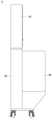
도 1은 본 발명의 일실시예에 따른 키오스크를 나타내는 사시도이다.
도 2는 본 발명의 일실시예에 따른 키오스크를 나타내는 정면도이다.
도 3은 본 발명의 일실시예에 따른 키오스크를 나타내는 좌측면도이다.
도 4는 본 발명의 일실시예에 따른 RFID 방식의 키오스크의 블록도이다.
도 5는 본 발명의 일실시예에 따른 수납모듈의 안테나 카세트 구조를 나타내는 도면이다.
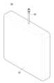
도 6은 본 발명의 일실시예에 따른 안테나 카세트를 나타내는 사시도이다.
도 7은 본 발명의 제1 실시예에 따른 키오스크의 수납공간 개폐구조를 나타내는 사시도이다.
도 8은 본 발명의 제2 실시예에 따른 키오스크의 수납공간 개폐구조를 나타내는 사시도이다.
도 9는 본 발명의 제3 실시예에 따른 키오스크의 수납공간 개폐구조를 나타내는 사시도이다.
도 10 내지 도 12는 본 발명의 제3 실시예에 따른 키오스크의 수납공간의 개방과정을 나타내는 단면도들이다.FIG. 1 is a perspective view showing a kiosk according to one embodiment of the present invention.
FIG. 2 is a front view showing a kiosk according to one embodiment of the present invention.
FIG. 3 is a left side view showing a kiosk according to one embodiment of the present invention.
FIG. 4 is a block diagram of an RFID-type kiosk according to an embodiment of the present invention.
FIG. 5 is a drawing showing the antenna cassette structure of a storage module according to one embodiment of the present invention.
FIG. 6 is a perspective view showing an antenna cassette according to one embodiment of the present invention.
Figure 7 is a perspective view showing the opening/closing structure of the storage space of a kiosk according to the first embodiment of the present invention.
Figure 8 is a perspective view showing the opening/closing structure of the storage space of a kiosk according to the second embodiment of the present invention.
FIG. 9 is a perspective view showing the opening/closing structure of the storage space of a kiosk according to the third embodiment of the present invention.
Figures 10 to 12 are cross-sectional views showing the process of opening a storage space of a kiosk according to a third embodiment of the present invention.
이하, 첨부된 도면을 참조하여 본 발명의 바람직한 실시예에 따른 모듈형 구조를 갖는 키오스크를 상세히 설명하기로 한다.Hereinafter, a kiosk having a modular structure according to a preferred embodiment of the present invention will be described in detail with reference to the attached drawings.
도 1은 본 발명의 일실시예에 따른 키오스크를 나타내는 사시도이며, 도 2는 본 발명의 일실시예에 따른 키오스크를 나타내는 정면도이며, 도 3은 본 발명의 일실시예에 따른 키오스크를 나타내는 좌측면도이다. 도 4는 본 발명의 일실시예에 따른 RFID 방식의 키오스크의 블록도이다.Fig. 1 is a perspective view showing a kiosk according to an embodiment of the present invention, Fig. 2 is a front view showing a kiosk according to an embodiment of the present invention, and Fig. 3 is a left side view showing a kiosk according to an embodiment of the present invention. Fig. 4 is a block diagram of an RFID-type kiosk according to an embodiment of the present invention.
도 1 내지 도 4를 참조하면, 키오스크(10)는 하부모듈(200) 상에 위치하며, 전면에 디스플레이(110), 바코드/RFID 리더기(120), 결재단말기(130)를 구비하는 상부모듈(100); 내부에는 통신부를 포함하는 컴퓨터 시스템인 제어부(210)와 RFID리더기(220)를 구비하는 하부모듈(200); 및 상면이 덮개(310)를 통하여 개폐될 수 있으며 상면에서 내측으로 내향되어 물품의 수납공간을 형성하며 수납공간의 벽면에 안테나 카세트(320)가 삽입되는 수납모듈(300)을 포함한다.Referring to FIGS. 1 to 4, the kiosk (10) comprises an upper module (100) positioned on a lower module (200) and having a display (110), a barcode/RFID reader (120), and a payment terminal (130) on the front; a lower module (200) having a control unit (210) and an RFID reader (220) which are computer systems including a communication unit inside; and a storage module (300) whose upper surface can be opened and closed through a cover (310) and which forms a storage space for items by facing inward from the upper surface, and in which an antenna cassette (320) is inserted into a wall of the storage space.
상기 상부모듈(100)의 디스플레이(110)는 터치형 디스플레이로서 입력된 명령에 따라 설정된 신호를 제어부(210)의 제어에 의한 물품 리스트 및 가격과, 결제정보를 출력할 수 있다. 상기 바코드/RFID 리더기(120)는 광신호를 통하여 물품에 부착된 RFID 태그 또는 바코드를 인식하여 제어부(210)로 전달한다. 상기 결제단말기(130)는 카드 투입구를 통해 투입된 카드 정보를 인식하고, 제어부(210)의 제어에 따라 카드사 서버와의 통신을 통하여 디스플레이(110)에 출력된 물품 가격을 정산한다.The display (110) of the upper module (100) is a touch-type display that can output a list of items and prices and payment information according to a signal set according to an input command under the control of the control unit (210). The barcode/RFID reader (120) recognizes an RFID tag or barcode attached to an item through an optical signal and transmits it to the control unit (210). The payment terminal (130) recognizes card information inserted through the card slot and settles the item price displayed on the display (110) through communication with the card company server according to the control of the control unit (210).
상기 하부모듈(200)의 제어부(210)는 안테나 카세트(320)로부터 인식된 물품 정보 및 가격을 확인하여 디스플레이(110)에 출력하도록 제어하고, 결제단말기(130)를 제어하여 결제를 진행하여 그 결과를 디스플레이(110)에 출력한다. 상기 RFID 리더기(220)는 수납모듈(320)의 내벽에 설치되는 복수의 안테나 카세트(320)로부터 태그의 신호를 전달받는다.The control unit (210) of the above lower module (200) checks the product information and price recognized from the antenna cassette (320) and controls them to output them to the display (110), and controls the payment terminal (130) to proceed with payment and output the result to the display (110). The RFID reader (220) receives the tag signal from a plurality of antenna cassettes (320) installed on the inner wall of the storage module (320).
상기 수납모듈(300)은 상면 또는 전면이 덮개(310)를 통하여 개폐될 수 있으며, 내측으로 내향되어 물품의 수납이 가능한 수납공간을 형성한다. 도면에 도시된 형상의 수납모듈(300)은 구체적으로는 전면, 후면, 양측면, 하부면과 상부에 덮개(310)를 갖는 차폐박스 형태이며, 안테나 카세트(320)를 포함하는 RFID 시스템이 구축되어 있다. RFID 시스템을 구성하기 위해서는 태그, 태그와 통신하기 위한 안테나, RFID 리더기가 필요하다.The storage module (300) above can be opened and closed through a cover (310) on the top or front, and forms a storage space inwardly facing to store items. The storage module (300) of the shape shown in the drawing is specifically in the form of a shield box having covers (310) on the front, back, both sides, bottom, and top, and an RFID system including an antenna cassette (320) is constructed. In order to configure an RFID system, a tag, an antenna for communicating with the tag, and an RFID reader are required.
RFID 시스템이 적용된 하부모듈(200)과 수납모듈(300)은 바코드와는 달리 물체에 직접 접촉을 하거나 어떤 조준선을 사용하지 않고도 데이터를 인식할 수 있다. 또한, 여러 개의 정보를 동시에 인식하거나 수정할 수 있으며, 태그와 리더 사이에 장애물이 있어도 정보를 인식하는 것이 가능하다.The lower module (200) and storage module (300) to which the RFID system is applied can recognize data without directly contacting an object or using any aiming line, unlike a barcode. In addition, multiple pieces of information can be recognized or modified simultaneously, and information can be recognized even when there is an obstacle between the tag and the reader.
도 5는 본 발명의 일실시예에 따른 수납모듈의 안테나 카세트 구조를 나타내는 도면이다.FIG. 5 is a drawing showing the antenna cassette structure of a storage module according to one embodiment of the present invention.
도 5를 참조하면, 안테나 카세트(320)는 키오스크의 수납모듈(300)의 양측의 벽면, 바닥면, 및 후면의 카세트홈(미도시)에 배치된다.Referring to FIG. 5, the antenna cassette (320) is placed in the cassette home (not shown) on the walls, floor, and rear of the storage module (300) of the kiosk on both sides.
각각 설치되는 복수의 안테나 카세트(320)는 외부 노출을 방지하도록 설치된다.The multiple antenna cassettes (320) that are installed separately are installed to prevent external exposure.
종래기술은 안테나를 키오스크의 벽면, 바닥면, 및 후면에 볼트와 브라켓을 사용하여 직접 조립하여 부착할 수도 있는데, 이 경우에는 향후 키오스크의 유지 보수에 필요한 작업이 복잡해질 수 있다. 따라서, 본 발명에서는 키오스크의 안테나를 카세트 방식으로 제작하여 키오스크 조립시에 안테나 카세트(320)를 수납모듈(300)에 삽입식으로 진행하여 향후 키오스크의 유지 보수에 편리하도록 설계한다.In the prior art, the antenna can be directly assembled and attached to the wall, floor, and back of the kiosk using bolts and brackets. However, in this case, the work required for future maintenance of the kiosk can become complicated. Therefore, in the present invention, the antenna of the kiosk is manufactured in a cassette format, and the antenna cassette (320) is inserted into the storage module (300) when assembling the kiosk, thereby facilitating future maintenance of the kiosk.
도 6은 본 발명의 일실시예에 따른 안테나 카세트를 나타내는 사시도이다.FIG. 6 is a perspective view showing an antenna cassette according to one embodiment of the present invention.
도 6을 참조하면, 본 발명의 안테나 카세트(320)는 직육면체의 슬림형의 카세트 본체(321)와 카세트 본체와 연결되는 단자(323)로 구성된다.Referring to FIG. 6, the antenna cassette (320) of the present invention is composed of a slim cassette body (321) in the shape of a rectangular solid and a terminal (323) connected to the cassette body.
본 발명의 수납모듈(300)은 상면 또는 전면이 덮개(310)를 통하여 개폐될 수 있으며, 내측으로 내향되어 물품의 수납이 가능한 수납공간을 형성한다. 수납모듈(300)은 덮개(310)와 수납공간의 형상에 따라 다양한 실시예가 가능하다.The storage module (300) of the present invention can be opened and closed through a cover (310) on the top or front surface, and forms a storage space inwardly facing to store items. The storage module (300) can have various embodiments depending on the shape of the cover (310) and the storage space.
도 7은 본 발명의 제1 실시예에 따른 키오스크의 수납공간 개폐구조를 나타내는 사시도이다.Figure 7 is a perspective view showing the opening/closing structure of the storage space of a kiosk according to the first embodiment of the present invention.
도 7을 참조하면, 수납모듈(301)의 덮개(311)는 하부모듈(201)의 상부에 형성된 레일을 따라서 슬라이딩하여 수납공간(331)을 개방할 수 있다.Referring to FIG. 7, the cover (311) of the storage module (301) can slide along a rail formed on the upper portion of the lower module (201) to open the storage space (331).
그런데, 제1 실시예는 덮개(311)의 폭만큼 하부모듈(201)의 폭이 넓어져야 하므로 부피가 커지는 문제가 있다. 나아가, 하부모듈(201)에서 수납모듈(301)을 분리하기가 곤란하여 키오스크의 완전한 모듈화에 한계가 있다.However, the first embodiment has a problem in that the width of the lower module (201) must be as wide as the width of the cover (311), so the volume increases. Furthermore, it is difficult to separate the storage module (301) from the lower module (201), so there is a limit to the complete modularization of the kiosk.
도 8은 본 발명의 제2 실시예에 따른 키오스크의 수납공간 개폐구조를 나타내는 사시도이다.Figure 8 is a perspective view showing the opening/closing structure of the storage space of a kiosk according to the second embodiment of the present invention.
도 8을 참조하면, 수납모듈(302)의 덮개(312)는 전면에 형성되어서 하부 힌지축을 따라서 회전하여 하부모듈(202) 전면으로 수납공간(332)을 개방할 수 있다. 제2 실시예는 수납공간 개폐구조가 하부모듈(202)과는 무관하므로 상대적으로 슬림한 키오스크를 구성할 수 있으며, 키오스크의 모듈화가 용이하다.Referring to Fig. 8, the cover (312) of the storage module (302) is formed on the front side and can be rotated along the lower hinge axis to open the storage space (332) to the front side of the lower module (202). Since the storage space opening/closing structure of the second embodiment is unrelated to the lower module (202), a relatively slim kiosk can be configured, and modularization of the kiosk is easy.
그런데, 제2 실시예는 물품을 수납공간(332)에 인입 및 인출하는 과정에서 허리를 굽혀야 하는 등 사용자에게 불편한 단점이 있다.However, the second embodiment has a disadvantage that makes it inconvenient for users, such as having to bend over when putting items in and taking them out of the storage space (332).
도 9는 본 발명의 제3 실시예에 따른 키오스크의 수납공간 개폐구조를 나타내는 사시도이다. 도 10 내지 도 12는 본 발명의 제3 실시예에 따른 키오스크의 수납공간의 개방과정을 나타내는 단면도들이다.Fig. 9 is a perspective view showing the opening/closing structure of the storage space of a kiosk according to the third embodiment of the present invention. Figs. 10 to 12 are cross-sectional views showing the opening process of the storage space of a kiosk according to the third embodiment of the present invention.
도 9 내지 도 12를 참조하면, 수납모듈(300)의 덮개(310)는 수납공간(330)의 상부 내측에 위치하는 수납공간측 힌지축(340)을 따라서 타원 형태의 회전을 하면서 후면 내측으로 이동하여 수납공간(330)을 개방할 수 있다.Referring to FIGS. 9 to 12, the cover (310) of the storage module (300) can open the storage space (330) by moving toward the rear inner side while rotating in an oval shape along the storage space-side hinge axis (340) located at the upper inner side of the storage space (330).
상기 하부모듈 덮개(310)의 개폐구조는, 상기 덮개의 전면 내측과 회전바의 일단부를 연결하는 덮개측 힌지축(350); 상기 수납공간(330) 상부 내측에 위치하며. 회전부의 타단부를 연결하는 수납공간측 힌지축(340); 상기 덮개측 힌지축(350)과 수납공간측 힌지축(340)을 연결하는 회전바(360); 및 상기 수납공간(330) 후방의 덮개홈(370)을 포함한다.The opening and closing structure of the lower module cover (310) includes a cover-side hinge axis (350) connecting the front inner side of the cover and one end of the rotating bar; a storage space-side hinge axis (340) located on the upper inner side of the storage space (330) and connecting the other end of the rotating part; a rotating bar (360) connecting the cover-side hinge axis (350) and the storage space-side hinge axis (340); and a cover groove (370) at the rear of the storage space (330).
도 10을 참조하면, 덮개(310)가 수납공간(330)의 상부에서 자중에 의하여 닫혀진 상태이다. 이때 회전바(360)는 수납공간(330)의 내측 전면에 위치한다.Referring to Fig. 10, the cover (310) is closed by its own weight at the top of the storage space (330). At this time, the rotating bar (360) is located at the inner front of the storage space (330).
도 11을 참조하면, 사용자가 덮개(310)를 들어올리면, 회전바(360)는 수납공간측 힌지축(340)을 따라서 타원 형태로 회전한다. 이때, 덮개(310)의 후단부는 덮개홈(370) 방향으로 인입된다.Referring to Fig. 11, when a user lifts the cover (310), the rotating bar (360) rotates in an oval shape along the hinge axis (340) on the storage space side. At this time, the rear end of the cover (310) is drawn in toward the cover groove (370).
도 12를 참조하면, 사용자가 덮개(310)를 계속 들어올리면, 덮개(310)는 자중에 의하여 덮개홈(370) 내부로 인입되어서 수납공간(330)은 완전 개방된다. 이때 회전바(360)는 수납공간(330)의 내측 후면에 위치한다.Referring to Fig. 12, when the user continues to lift the cover (310), the cover (310) is pulled into the cover groove (370) by its own weight, so that the storage space (330) is completely opened. At this time, the rotating bar (360) is located at the inner rear side of the storage space (330).
이와 같은 제3 실시예의 덮개는 제1 실시예보다는 슬림하게 키오스크를 구성할 수 있으면서도 키오스크의 모듈화가 용이하며, 제2 실시예와는 달리 상부면을 개방하여 사용자가 편리하게 키오스크를 이용할 수 있다.The cover of the third embodiment allows the kiosk to be configured slimmer than the first embodiment while facilitating modularization of the kiosk, and unlike the second embodiment, the upper surface is open so that the user can conveniently use the kiosk.
이하, 모듈형 구조를 갖는 키오스크의 사용방법에 관하여 설명한다.Below, the method of using a kiosk with a modular structure is described.
먼저, 물품에 RFID 태그가 부착되어 있으며, 사용자는 다수의 물품을 수납공간(330, 331, 332)의 덮개(310, 311, 312)를 개방한 후에 수납공간(330, 331, 332)에 넣는다.First, an RFID tag is attached to an item, and the user places multiple items into the storage space (330, 331, 332) after opening the cover (310, 311, 312) of the storage space (330, 331, 332).
다음으로, 사용자는 수납공간(330, 331, 332)의 덮개(310, 311, 312)를 닫는다.Next, the user closes the cover (310, 311, 312) of the storage space (330, 331, 332).
다음으로, 사용자가 키오스크 상부모듈(100)의 디스플레이(110)의 RFID 스캔아이콘을 터치하면, 하부모듈(200)에 위치하는 RFID 리더기(220)에서는 안테나 카세트(320)를 통해 RFID 태그를 향해 무선 신호를 송출한다. RFID 태그는 신호에 반응하여 태그에 저장된 데이터를 송출한다. 태그로부터 신호를 수신한 안테나 카세트(320)는 수신한 데이터를 디지털 신호로 변조하여 RFID 리더기(220)로 전달한다. RFID 리더기(220)는 데이터를 해독하여 제어부(210)로 전달한다. 제어부(210)는 키오스크 상부모듈(100)의 디스플레이(110)에 해독한 데이터를 표시한다.Next, when the user touches the RFID scan icon on the display (110) of the upper module (100) of the kiosk, the RFID reader (220) located in the lower module (200) transmits a wireless signal toward the RFID tag through the antenna cassette (320). The RFID tag responds to the signal and transmits data stored in the tag. The antenna cassette (320) that receives the signal from the tag modulates the received data into a digital signal and transmits it to the RFID reader (220). The RFID reader (220) decodes the data and transmits it to the control unit (210). The control unit (210) displays the decoded data on the display (110) of the upper module (100) of the kiosk.
다음으로, 사용자는 키오스크 상부모듈(100)의 디스플레이(110)에서 담겨진 물품을 확인한다.Next, the user checks the contained items on the display (110) of the upper module (100) of the kiosk.
이후에 사용자는 필요에 따라서 물품의 결제 또는 취소를 선택할 수 있다.Afterwards, the user can choose to pay for or cancel the item as needed.
이상에서 설명한 본 발명은 전술한 도면 및 상세한 설명에 의하여 한정되는 것은 아니고, 하기의 특허청구범위에 기재된 본 발명의 사상 및 영역으로부터 벗어나지 않는 범위 내에서 해당 기술분야의 당업자가 다양하게 수정 및 변경시킨 것 또한 본 발명의 범위 내에 포함됨은 물론이다.The present invention described above is not limited to the above-described drawings and detailed description, and it goes without saying that various modifications and changes made by those skilled in the art within the scope and spirit of the present invention as described in the claims below are also included within the scope of the present invention.
10: 키오스크 100: 상부모듈
110: 디스플레이 120: 바코드/RFID 리더기
130: 결제단말기 200, 201, 202: 하부모듈
210: 제어부 220: RFID 리더기
300, 301, 302: 수납모듈 310, 311, 312: 덮개
320: 안테나 카세트 321: 카세트 본체
323: 단자 330, 331, 332: 수납공간
340: 수납공간측 힌지축 350: 덮개측 힌지축
360: 회전바 370: 덮개홈10: Kiosk 100: Top module
110: Display 120: Barcode/RFID Reader
130:
210: Control unit 220: RFID reader
300, 301, 302:
320: Antenna cassette 321: Cassette body
323:
340: Hinge axis on storage space side 350: Hinge axis on cover side
360: Rotating bar 370: Cover groove
Claims (7)
Translated fromKorean상기 상부모듈 하부에 착탈 가능하게 결합되며, 내부에는 통신부를 포함하는 컴퓨터 시스템인 제어부와 RFID 리더기를 구비하는 하부모듈; 및
상기 하부모듈과 인접하게 착탈 가능하게 결합되며, 덮개를 통하여 개폐될 수 있으며, 상기 덮개에서 내측으로 내향되어 물품의 수납공간을 형성하며, 상기 수납공간의 내벽에 안테나 카세트가 삽입되는 수납모듈을 포함하는 모듈형 구조를 갖는 키오스크.An upper module positioned on the lower module and having a display on the front;
A lower module detachably coupled to the lower part of the upper module and having a control unit, which is a computer system including a communication unit, and an RFID reader inside; and
A kiosk having a modular structure including a storage module that is detachably connected adjacent to the above-mentioned lower module and can be opened and closed through a cover, and forms a storage space for items by facing inward from the cover, and into which an antenna cassette is inserted into the inner wall of the storage space.
상기 상부모듈은 전면에 디스플레이, 바코드/RFID 리더기, 결재단말기를 구비하는 것을 특징으로 하는 모듈형 구조를 갖는 키오스크.In the first paragraph,
A kiosk having a modular structure characterized by the upper module having a display, a barcode/RFID reader, and a payment terminal on the front.
상기 안테나 카세트는 키오스크의 수납모듈의 양측의 벽면, 바닥면, 및 후면의 카세트홈에 배치되는 것을 특징으로 하는 모듈형 구조를 갖는 키오스크.In the first paragraph,
A kiosk having a modular structure, characterized in that the antenna cassette is placed in the cassette home on the walls, floor, and rear of both sides of the storage module of the kiosk.
상기 하부모듈의 덮개는 하부모듈의 상부에 형성된 레일을 따라서 슬라이딩하여 수납공간을 개방할 수 있는 것을 특징으로 하는 모듈형 구조를 갖는 키오스크.In the first paragraph,
A kiosk having a modular structure, characterized in that the cover of the lower module can open a storage space by sliding along a rail formed on the upper part of the lower module.
상기 하부모듈의 덮개는 하부모듈의 전면에 형성되어서 하부 힌지축을 따라서 회전하여 전면으로 수납공간을 개방할 수 있는 것을 특징으로 하는 모듈형 구조를 갖는 키오스크.In the first paragraph,
A kiosk having a modular structure, characterized in that the cover of the lower module is formed on the front side of the lower module and can rotate along the lower hinge axis to open a storage space to the front side.
상기 하부모듈의 덮개는 수납공간의 상부 내측에 위치하는 수납공간측 힌지축을 따라서 타원 형태의 회전을 하면서 후면 내측으로 이동하여 수납공간을 개방할 수 있는 것을 특징으로 하는 모듈형 구조를 갖는 키오스크.In the first paragraph,
A kiosk having a modular structure, characterized in that the cover of the lower module can open the storage space by moving toward the rear inner side while rotating in an oval shape along the storage space-side hinge axis located on the upper inner side of the storage space.
상기 하부모듈 덮개의 개폐구조는,
상기 덮개의 전면 내측과 회전바의 일단부를 연결하는 덮개측 힌지축;
상기 수납공간 상부 내측에 위치하며, 회전부의 타단부를 연결하는 수납공간측 힌지축;
상기 덮개측 힌지축과 수납공간측 힌지축을 연결하는 회전바; 및
상기 수납공간 후방의 덮개홈을 포함하는 것을 특징으로 하는 모듈형 구조를 갖는 키오스크.In Article 6,
The opening and closing structure of the above lower module cover is:
A cover-side hinge axis connecting the front inner side of the cover and one end of the rotating bar;
A hinge axis on the storage space side, located on the upper inner side of the storage space and connecting the other end of the rotating part;
A rotating bar connecting the hinge axis on the cover side and the hinge axis on the storage space side; and
A kiosk having a modular structure, characterized by including a cover groove at the rear of the storage space.
Priority Applications (1)
| Application Number | Priority Date | Filing Date | Title |
|---|---|---|---|
| KR1020230062369AKR102829734B1 (en) | 2023-05-15 | 2023-05-15 | Kiosk with modular structure |
Applications Claiming Priority (1)
| Application Number | Priority Date | Filing Date | Title |
|---|---|---|---|
| KR1020230062369AKR102829734B1 (en) | 2023-05-15 | 2023-05-15 | Kiosk with modular structure |
Publications (2)
| Publication Number | Publication Date |
|---|---|
| KR20240165080Atrue KR20240165080A (en) | 2024-11-22 |
| KR102829734B1 KR102829734B1 (en) | 2025-07-04 |
Family
ID=93705395
Family Applications (1)
| Application Number | Title | Priority Date | Filing Date |
|---|---|---|---|
| KR1020230062369AActiveKR102829734B1 (en) | 2023-05-15 | 2023-05-15 | Kiosk with modular structure |
Country Status (1)
| Country | Link |
|---|---|
| KR (1) | KR102829734B1 (en) |
Citations (6)
| Publication number | Priority date | Publication date | Assignee | Title |
|---|---|---|---|---|
| JP2015207119A (en)* | 2014-04-18 | 2015-11-19 | 東芝テック株式会社 | Reading device and item sales data processing apparatus |
| JP2017228139A (en)* | 2016-06-23 | 2017-12-28 | 東芝テック株式会社 | POS device |
| WO2019049953A1 (en)* | 2017-09-07 | 2019-03-14 | パナソニックIpマネジメント株式会社 | Shopping assist system and shopping assist method |
| KR200490632Y1 (en) | 2018-04-02 | 2019-12-10 | (주)에어포스 | Kiosk |
| KR102300307B1 (en) | 2021-01-12 | 2021-09-09 | 안은희 | Unmanned checkout counter of rfid type |
| KR102382120B1 (en) | 2021-05-11 | 2022-04-01 | 김용구 | Hybrid Self payment system using barcode and RFID |
- 2023
- 2023-05-15KRKR1020230062369Apatent/KR102829734B1/enactiveActive
Patent Citations (6)
| Publication number | Priority date | Publication date | Assignee | Title |
|---|---|---|---|---|
| JP2015207119A (en)* | 2014-04-18 | 2015-11-19 | 東芝テック株式会社 | Reading device and item sales data processing apparatus |
| JP2017228139A (en)* | 2016-06-23 | 2017-12-28 | 東芝テック株式会社 | POS device |
| WO2019049953A1 (en)* | 2017-09-07 | 2019-03-14 | パナソニックIpマネジメント株式会社 | Shopping assist system and shopping assist method |
| KR200490632Y1 (en) | 2018-04-02 | 2019-12-10 | (주)에어포스 | Kiosk |
| KR102300307B1 (en) | 2021-01-12 | 2021-09-09 | 안은희 | Unmanned checkout counter of rfid type |
| KR102382120B1 (en) | 2021-05-11 | 2022-04-01 | 김용구 | Hybrid Self payment system using barcode and RFID |
Also Published As
| Publication number | Publication date |
|---|---|
| KR102829734B1 (en) | 2025-07-04 |
Similar Documents
| Publication | Publication Date | Title |
|---|---|---|
| JP4542186B2 (en) | Self-checkout kiosk and retail security system | |
| US9519897B2 (en) | Reading apparatus and commodity sales data processing apparatus | |
| US11694501B2 (en) | Refrigerated vending system and method | |
| US20150302228A1 (en) | Reading apparatus and reading method | |
| CN101625784A (en) | Supermarket shopping account settling device and self-help account settling method | |
| JP6569057B2 (en) | Checkout processing system and store management system | |
| CN107590926B (en) | Unattended sales system | |
| US20210174328A1 (en) | Article management system and article management method | |
| US5079412A (en) | Point of sale data processing apparatus for handy type bar code reader which can be flush mounted | |
| CN108171876A (en) | Self-service counter, system and its good selling method | |
| CN202563593U (en) | Self-service vending machine | |
| US6857505B1 (en) | Apparatus and method for utilizing an existing software application during operation of a convertible checkout terminal | |
| CN205541115U (en) | Cabinet and intelligence system of selling are sold to intelligence | |
| KR102300307B1 (en) | Unmanned checkout counter of rfid type | |
| CN207742732U (en) | A kind of small boxed commodities automatic vending case | |
| KR102829734B1 (en) | Kiosk with modular structure | |
| EP3499403B1 (en) | Commodity information reading apparatus | |
| CN208673467U (en) | RFID self-service with function of weighing purchases intelligent cashier system | |
| JP5903396B2 (en) | Product sales data processing device and product sales unit | |
| JP4704119B2 (en) | Checkout system | |
| US20190362607A1 (en) | Accounting apparatus and method therefor | |
| JP7387483B2 (en) | Product information registration device, program, and product information registration system | |
| JP5789625B2 (en) | Product sales data processing device | |
| KR102628614B1 (en) | Unmanned Checkout Counter of RFID | |
| KR102665663B1 (en) | Unmanned vending machine |
Legal Events
| Date | Code | Title | Description |
|---|---|---|---|
| PA0109 | Patent application | Patent event code:PA01091R01D Comment text:Patent Application Patent event date:20230515 | |
| PA0201 | Request for examination | Patent event code:PA02011R01I Patent event date:20230515 Comment text:Patent Application | |
| PG1501 | Laying open of application | ||
| E902 | Notification of reason for refusal | ||
| PE0902 | Notice of grounds for rejection | Comment text:Notification of reason for refusal Patent event date:20250408 Patent event code:PE09021S01D | |
| E701 | Decision to grant or registration of patent right | ||
| PE0701 | Decision of registration | Patent event code:PE07011S01D Comment text:Decision to Grant Registration Patent event date:20250429 | |
| GRNT | Written decision to grant | ||
| PR0701 | Registration of establishment | Comment text:Registration of Establishment Patent event date:20250701 Patent event code:PR07011E01D | |
| PR1002 | Payment of registration fee | Payment date:20250701 End annual number:3 Start annual number:1 | |
| PG1601 | Publication of registration |