KR20240158463A - Humidifier - Google Patents
HumidifierDownload PDFInfo
- Publication number
- KR20240158463A KR20240158463AKR1020230055139AKR20230055139AKR20240158463AKR 20240158463 AKR20240158463 AKR 20240158463AKR 1020230055139 AKR1020230055139 AKR 1020230055139AKR 20230055139 AKR20230055139 AKR 20230055139AKR 20240158463 AKR20240158463 AKR 20240158463A
- Authority
- KR
- South Korea
- Prior art keywords
- case
- humidifier
- filter
- cover
- humidifying
- Prior art date
- Legal status (The legal status is an assumption and is not a legal conclusion. Google has not performed a legal analysis and makes no representation as to the accuracy of the status listed.)
- Pending
Links
Images


Classifications
- F—MECHANICAL ENGINEERING; LIGHTING; HEATING; WEAPONS; BLASTING
- F24—HEATING; RANGES; VENTILATING
- F24F—AIR-CONDITIONING; AIR-HUMIDIFICATION; VENTILATION; USE OF AIR CURRENTS FOR SCREENING
- F24F6/00—Air-humidification, e.g. cooling by humidification
- F24F6/02—Air-humidification, e.g. cooling by humidification by evaporation of water in the air
- F24F6/08—Air-humidification, e.g. cooling by humidification by evaporation of water in the air using heated wet elements
- F24F6/10—Air-humidification, e.g. cooling by humidification by evaporation of water in the air using heated wet elements heated electrically
- F—MECHANICAL ENGINEERING; LIGHTING; HEATING; WEAPONS; BLASTING
- F24—HEATING; RANGES; VENTILATING
- F24F—AIR-CONDITIONING; AIR-HUMIDIFICATION; VENTILATION; USE OF AIR CURRENTS FOR SCREENING
- F24F6/00—Air-humidification, e.g. cooling by humidification
- F24F6/02—Air-humidification, e.g. cooling by humidification by evaporation of water in the air
- F24F6/025—Air-humidification, e.g. cooling by humidification by evaporation of water in the air using electrical heating means
- A—HUMAN NECESSITIES
- A61—MEDICAL OR VETERINARY SCIENCE; HYGIENE
- A61L—METHODS OR APPARATUS FOR STERILISING MATERIALS OR OBJECTS IN GENERAL; DISINFECTION, STERILISATION OR DEODORISATION OF AIR; CHEMICAL ASPECTS OF BANDAGES, DRESSINGS, ABSORBENT PADS OR SURGICAL ARTICLES; MATERIALS FOR BANDAGES, DRESSINGS, ABSORBENT PADS OR SURGICAL ARTICLES
- A61L9/00—Disinfection, sterilisation or deodorisation of air
- A61L9/16—Disinfection, sterilisation or deodorisation of air using physical phenomena
- A61L9/18—Radiation
- A61L9/20—Ultraviolet radiation
- B—PERFORMING OPERATIONS; TRANSPORTING
- B01—PHYSICAL OR CHEMICAL PROCESSES OR APPARATUS IN GENERAL
- B01D—SEPARATION
- B01D46/00—Filters or filtering processes specially modified for separating dispersed particles from gases or vapours
- B01D46/0002—Casings; Housings; Frame constructions
- B01D46/0004—Details of removable closures, lids, caps or filter heads
- B—PERFORMING OPERATIONS; TRANSPORTING
- B01—PHYSICAL OR CHEMICAL PROCESSES OR APPARATUS IN GENERAL
- B01D—SEPARATION
- B01D46/00—Filters or filtering processes specially modified for separating dispersed particles from gases or vapours
- B01D46/0027—Filters or filtering processes specially modified for separating dispersed particles from gases or vapours with additional separating or treating functions
- B01D46/0028—Filters or filtering processes specially modified for separating dispersed particles from gases or vapours with additional separating or treating functions provided with antibacterial or antifungal means
- B—PERFORMING OPERATIONS; TRANSPORTING
- B01—PHYSICAL OR CHEMICAL PROCESSES OR APPARATUS IN GENERAL
- B01D—SEPARATION
- B01D46/00—Filters or filtering processes specially modified for separating dispersed particles from gases or vapours
- B01D46/0039—Filters or filtering processes specially modified for separating dispersed particles from gases or vapours with flow guiding by feed or discharge devices
- B01D46/0041—Filters or filtering processes specially modified for separating dispersed particles from gases or vapours with flow guiding by feed or discharge devices for feeding
- F—MECHANICAL ENGINEERING; LIGHTING; HEATING; WEAPONS; BLASTING
- F24—HEATING; RANGES; VENTILATING
- F24F—AIR-CONDITIONING; AIR-HUMIDIFICATION; VENTILATION; USE OF AIR CURRENTS FOR SCREENING
- F24F13/00—Details common to, or for air-conditioning, air-humidification, ventilation or use of air currents for screening
- F24F13/20—Casings or covers
- F—MECHANICAL ENGINEERING; LIGHTING; HEATING; WEAPONS; BLASTING
- F24—HEATING; RANGES; VENTILATING
- F24F—AIR-CONDITIONING; AIR-HUMIDIFICATION; VENTILATION; USE OF AIR CURRENTS FOR SCREENING
- F24F13/00—Details common to, or for air-conditioning, air-humidification, ventilation or use of air currents for screening
- F24F13/28—Arrangement or mounting of filters
- F—MECHANICAL ENGINEERING; LIGHTING; HEATING; WEAPONS; BLASTING
- F24—HEATING; RANGES; VENTILATING
- F24F—AIR-CONDITIONING; AIR-HUMIDIFICATION; VENTILATION; USE OF AIR CURRENTS FOR SCREENING
- F24F6/00—Air-humidification, e.g. cooling by humidification
- F24F6/12—Air-humidification, e.g. cooling by humidification by forming water dispersions in the air
- F—MECHANICAL ENGINEERING; LIGHTING; HEATING; WEAPONS; BLASTING
- F24—HEATING; RANGES; VENTILATING
- F24F—AIR-CONDITIONING; AIR-HUMIDIFICATION; VENTILATION; USE OF AIR CURRENTS FOR SCREENING
- F24F8/00—Treatment, e.g. purification, of air supplied to human living or working spaces otherwise than by heating, cooling, humidifying or drying
- F24F8/10—Treatment, e.g. purification, of air supplied to human living or working spaces otherwise than by heating, cooling, humidifying or drying by separation, e.g. by filtering
- F24F8/108—Treatment, e.g. purification, of air supplied to human living or working spaces otherwise than by heating, cooling, humidifying or drying by separation, e.g. by filtering using dry filter elements
- F—MECHANICAL ENGINEERING; LIGHTING; HEATING; WEAPONS; BLASTING
- F24—HEATING; RANGES; VENTILATING
- F24F—AIR-CONDITIONING; AIR-HUMIDIFICATION; VENTILATION; USE OF AIR CURRENTS FOR SCREENING
- F24F8/00—Treatment, e.g. purification, of air supplied to human living or working spaces otherwise than by heating, cooling, humidifying or drying
- F24F8/20—Treatment, e.g. purification, of air supplied to human living or working spaces otherwise than by heating, cooling, humidifying or drying by sterilisation
- F24F8/22—Treatment, e.g. purification, of air supplied to human living or working spaces otherwise than by heating, cooling, humidifying or drying by sterilisation using UV light
- A—HUMAN NECESSITIES
- A61—MEDICAL OR VETERINARY SCIENCE; HYGIENE
- A61L—METHODS OR APPARATUS FOR STERILISING MATERIALS OR OBJECTS IN GENERAL; DISINFECTION, STERILISATION OR DEODORISATION OF AIR; CHEMICAL ASPECTS OF BANDAGES, DRESSINGS, ABSORBENT PADS OR SURGICAL ARTICLES; MATERIALS FOR BANDAGES, DRESSINGS, ABSORBENT PADS OR SURGICAL ARTICLES
- A61L2209/00—Aspects relating to disinfection, sterilisation or deodorisation of air
- A61L2209/10—Apparatus features
- A61L2209/12—Lighting means
- A—HUMAN NECESSITIES
- A61—MEDICAL OR VETERINARY SCIENCE; HYGIENE
- A61L—METHODS OR APPARATUS FOR STERILISING MATERIALS OR OBJECTS IN GENERAL; DISINFECTION, STERILISATION OR DEODORISATION OF AIR; CHEMICAL ASPECTS OF BANDAGES, DRESSINGS, ABSORBENT PADS OR SURGICAL ARTICLES; MATERIALS FOR BANDAGES, DRESSINGS, ABSORBENT PADS OR SURGICAL ARTICLES
- A61L2209/00—Aspects relating to disinfection, sterilisation or deodorisation of air
- A61L2209/10—Apparatus features
- A61L2209/14—Filtering means
- B—PERFORMING OPERATIONS; TRANSPORTING
- B01—PHYSICAL OR CHEMICAL PROCESSES OR APPARATUS IN GENERAL
- B01D—SEPARATION
- B01D2279/00—Filters adapted for separating dispersed particles from gases or vapours specially modified for specific uses
- B01D2279/40—Filters adapted for separating dispersed particles from gases or vapours specially modified for specific uses for cleaning of environmental air, e.g. by filters installed on vehicles or on streets
- F—MECHANICAL ENGINEERING; LIGHTING; HEATING; WEAPONS; BLASTING
- F24—HEATING; RANGES; VENTILATING
- F24F—AIR-CONDITIONING; AIR-HUMIDIFICATION; VENTILATION; USE OF AIR CURRENTS FOR SCREENING
- F24F6/00—Air-humidification, e.g. cooling by humidification
- F24F2006/008—Air-humidifier with water reservoir
- F—MECHANICAL ENGINEERING; LIGHTING; HEATING; WEAPONS; BLASTING
- F24—HEATING; RANGES; VENTILATING
- F24F—AIR-CONDITIONING; AIR-HUMIDIFICATION; VENTILATION; USE OF AIR CURRENTS FOR SCREENING
- F24F13/00—Details common to, or for air-conditioning, air-humidification, ventilation or use of air currents for screening
- F24F13/20—Casings or covers
- F24F2013/205—Mounting a ventilator fan therein
- F—MECHANICAL ENGINEERING; LIGHTING; HEATING; WEAPONS; BLASTING
- F24—HEATING; RANGES; VENTILATING
- F24F—AIR-CONDITIONING; AIR-HUMIDIFICATION; VENTILATION; USE OF AIR CURRENTS FOR SCREENING
- F24F2221/00—Details or features not otherwise provided for
- F24F2221/36—Modules, e.g. for an easy mounting or transport
Landscapes
- Engineering & Computer Science (AREA)
- Chemical & Material Sciences (AREA)
- Combustion & Propulsion (AREA)
- Mechanical Engineering (AREA)
- General Engineering & Computer Science (AREA)
- Chemical Kinetics & Catalysis (AREA)
- Health & Medical Sciences (AREA)
- Dispersion Chemistry (AREA)
- Epidemiology (AREA)
- Life Sciences & Earth Sciences (AREA)
- Animal Behavior & Ethology (AREA)
- General Health & Medical Sciences (AREA)
- Public Health (AREA)
- Veterinary Medicine (AREA)
- Air Humidification (AREA)
Abstract
Translated fromKoreanDescription
Translated fromKorean본 개시는 가습기에 관한 것으로, 보다 상세하게는 가습된 청정공기를 공급하는 가습기에 관한 것이다.The present disclosure relates to a humidifier, and more particularly, to a humidifier that supplies humidified clean air.
가습기는 수분을 함유한 공기를 실내로 공급하는 장치이다. 가습기는 물을 저장하는 물통을 구비하며, 가습방식에 따라 초음파식, 가열식, 자연기화식 또는 복합식으로 구분된다.A humidifier is a device that supplies air containing moisture to a room. Humidifiers are equipped with a water tank to store water, and are classified into ultrasonic, heating, natural evaporation, or combined types depending on the humidification method.
가습기는 물을 기화하여 수분함유량이 높은 가습공기를 배출시키는 장치이다. 가습기는 자연기화, 가열기화, 초음파진동에 의해 물을 기화하여 가습공기를 생성시킬 수 있다.A humidifier is a device that vaporizes water and emits humidified air with a high moisture content. A humidifier can vaporize water by natural vaporization, heating vaporization, or ultrasonic vibration to create humidified air.
각각의 기화방식에는 장단점이 있다. 자연기화의 경우, 사용되는 가습매체를 사용자가 빈번하게 관리해야하는 문제점이 있다.Each vaporization method has its advantages and disadvantages. In the case of natural vaporization, there is the problem that the user must frequently manage the humidifying medium used.
초음파식 가습기는 초음파를 이용해 진동을 발생시키는 진동자를 구비하며, 진동자의 진동에 의해 미립자 형태로 변화된 물을 분사하는데, 분무량이 많다는 장점이 있다. 초음파진동에 의한 기화의 경우, 공급된 물을 초음파 진동으로 무화시키는 것으로 가습된공기가 실내공간으로 유동이 활발하지 않을 수 있는 문제, 살균되지 않은 물이 가습되는 경우 실내공간으로 불쾌한 가습공기가 유동할 수 있는 문제, 초음파 진동자가 고온의 열에 취약한 문제가 있다.Ultrasonic humidifiers have a vibrator that generates vibrations using ultrasonic waves, and spray water that has been changed into a fine particle form by the vibration of the vibrator, and have the advantage of a large spray volume. In the case of vaporization by ultrasonic vibration, there are problems such as the humidified air may not flow actively into the indoor space because the supplied water is atomized by ultrasonic vibration, the problem that unpleasant humidified air may flow into the indoor space if unsterilized water is humidified, and the problem that the ultrasonic vibrator is vulnerable to high temperature.
가열기화의 경우, 뜨거운 가습공기가 직접적으로 토출되는 경우 안전사고의 문제가 발생할 수 있다.In the case of heated vaporization, a safety hazard may occur if hot humidified air is directly discharged.
선행문헌 한국 등록 특허 KR 10-0158806호에서는 물탱크에서 공급된 물을 가열 및 초음파 진동으로 가습하는 가습기를 개시하고 있다. 이러한 종래 가습기는, 장치 내부에 고여있는 물에 의해 장치의 청결상태가 저하되는 문제가 있다. 이에, 장치로부터 분무되는 공기의 오염도가 높은 문제가 야기된다.Prior art Korean patent registration KR 10-0158806 discloses a humidifier that heats and humidifies water supplied from a water tank by ultrasonic vibration. Such conventional humidifiers have a problem in that the cleanliness of the device deteriorates due to water accumulated inside the device. This causes a problem in that the air sprayed from the device is highly contaminated.
또한, 가습기는, 흡입되는 공기를 필터링하도록 내부에 필터를 구비하여, 청정공기를 제공할 수 있다. 외부의 공기가 유입되어 유동하는 구조상, 필터나 공기청정기 내부에 배치되는 팬에 세균이나 미생물이 누적될 수 있다. 이는 실내공간으로 토출되는 공기에 혼합될 수 있는 문제가 될 수 있다.In addition, the humidifier can provide clean air by having a filter inside to filter the air being inhaled. Since the outside air is drawn in and flows, bacteria or microorganisms can accumulate in the filter or the fan placed inside the air purifier. This can be a problem that can be mixed with the air discharged into the indoor space.
선행문헌 한국 공개 특허 KR 10-2021-0138353은, 필터를 살균하기 위한 램프를 개시하고 있으나, 구체적인 배치가 구조에 대해서는 개시하고 있지 않고, 시간의 경과에 따라, 팬에 세균이나 미생물 등이 누적되고, 이로 인해 필터에 의한 공기정화 성능이 저하되는 문제가 있었다.Prior literature Korean published patent KR 10-2021-0138353 discloses a lamp for sterilizing a filter, but does not disclose a specific arrangement or structure, and there was a problem that bacteria and microorganisms accumulated in the fan over time, resulting in a deterioration in the air purification performance of the filter.
따라서, 장치 내부를 청결하게 관리할 수 있는 종합적인 방법에 대한 많은 연구가 이루어지고 있다.Therefore, much research is being conducted on comprehensive methods to keep the inside of the device clean.
본 개시는 전술한 문제점 및 다른 문제를 해결하는 것을 목적으로 한다.The present disclosure aims to solve the above-mentioned problems and other problems.
본 개시의 목적은 깨끗한 가습 공기를 배출하는 가습기를 제공하는 것이다.An object of the present disclosure is to provide a humidifier that emits clean humidified air.
본 개시의 목적은 내부 위생관리가 용이한 가습기를 제공하는 것이다.The purpose of the present disclosure is to provide a humidifier with easy internal hygiene management.
본 개시의 목적은 팬, 필터, 가습챔버를 살균할 수 있는 가습기를 제공하는 것이다.The purpose of the present disclosure is to provide a humidifier capable of sterilizing a fan, a filter, and a humidifying chamber.
본 개시의 목적은 자외선이 외부로 유출되는 것을 방지할 수 있는 가습기를 제공하는 것이다.The purpose of the present disclosure is to provide a humidifier capable of preventing ultraviolet rays from leaking outside.
본 개시의 목적은 가열챔버에서 발생되는 가습공기와 가습챔버에서 발생된 가습공기를 함께 배출시키는 가습기를 제공하는 것이다.The purpose of the present disclosure is to provide a humidifier that discharges humidified air generated in a heating chamber and humidified air generated in a humidifying chamber together.
본 개시의 과제들은 이상에서 언급한 과제들로 제한되지 않으며, 언급되지 않은 또 다른 과제들은 아래의 기재로부터 당업자에게 명확하게 이해될 수 있을 것이다.The tasks of the present disclosure are not limited to the tasks mentioned above, and other tasks not mentioned will be clearly understood by those skilled in the art from the description below.
상기 과제를 달성하기 위하여, 본 개시의 실시 예에 따른 가습기는, 자외선 광으로 필터, 팬, 가습수조 중 적어도 하나를 살균할 수 있다.To achieve the above task, a humidifier according to an embodiment of the present disclosure can sterilize at least one of a filter, a fan, and a humidifying tank with ultraviolet light.
상기 과제를 달성하기 위하여, 본 개시의 실시 예에 따른 가습기는, 케이스 결합 여부, 필터 안착 여부에 따라, 자외선 광 조사 여부를 제어함으로써, 안전성을 강화할 수 있다.In order to achieve the above task, the humidifier according to the embodiment of the present disclosure can enhance safety by controlling whether to irradiate ultraviolet light depending on whether the case is combined and whether the filter is installed.
상기 과제를 달성하기 위하여, 본 개시의 실시 예에 따른 가습기는, 케이스,상기 케이스 하측에 배치되는 베이스, 상기 베이스 상측에 배치되고, 상기 케이스가 분리 가능하게 결합되는 베이스 커버, 상기 케이스 내부에 배치되고, 분무를 생성하는 가습어셈블리, 상기 가습어셈블리의 하측에 배치되는 필터, 및, 상기 베이스 커버에 배치되고, 자외선 광을 조사하는 살균모듈을 포함하고, 상기 살균모듈은, 상기 베이스 커버에 상기 케이스가 결합되고 상기 필터가 안착되면, 상기 필터 내부 중공으로 자외선 광을 조사함으로써, 안전 사고 발생을 방지하면서, 내부 위생을 관리할 수 있다.In order to achieve the above object, a humidifier according to an embodiment of the present disclosure includes a case, a base disposed on a lower side of the case, a base cover disposed on an upper side of the base and to which the case is detachably coupled, a humidifying assembly disposed inside the case and generating spray, a filter disposed on a lower side of the humidifying assembly, and a sterilizing module disposed on the base cover and irradiating ultraviolet light, wherein the sterilizing module irradiates ultraviolet light into a hollow space inside the filter when the case is coupled to the base cover and the filter is secured, thereby preventing the occurrence of safety accidents and managing internal hygiene.
본 개시의 실시 예에 따른 가습기는, 상기 필터의 상측에 배치되고, 상기 필터의 둘레면으로부터 유입된 공기를 상기 필터의 상측으로 유동시키는 팬을 더 포함할 수 있다.A humidifier according to an embodiment of the present disclosure may further include a fan disposed above the filter and causing air drawn in from a peripheral surface of the filter to flow to the upper side of the filter.
상기 케이스는, 상기 베이스 커버에 분리 가능하게 결합되는 제1 케이스, 및, 상기 베이스 커버에 대하여 상기 제1 케이스와 대향하고, 상기 베이스 커버에 분리 가능하게 결합되는 제2 케이스를 더 포함하고, 상기 살균 모듈은, 상기 제1 케이스와 상기 제2 케이스 중에 적어도 하나가 상기 베이스 커버에서 분리되면, 상기 자외선 광의 조사를 중지시킬 수 있다.The case further includes a first case detachably coupled to the base cover, and a second case facing the first case with respect to the base cover and detachably coupled to the base cover, and the sterilizing module can stop irradiating the ultraviolet light when at least one of the first case and the second case is detached from the base cover.
상기 베이스 커버는, 상기 제1 케이스가 상기 베이스 커버에 결합되면 동작하는 제1 버튼과, 상기 제2 케이스가 상기 베이스 커버에 결합되면 동작하는 제2 버튼을 포함할 수 있다.The above base cover may include a first button that operates when the first case is coupled to the base cover, and a second button that operates when the second case is coupled to the base cover.
상기 제1 케이스는, 상기 제1 케이스의 내면에서 돌출되고, 상기 제1 버튼과 접촉하는 제1 리브를 포함하고, 상기 제2 케이스는, 상기 제2 케이스의 내면에서 돌출되고, 상기 제2 버튼과 접촉하는 제2 리브를 포함할 수 있다.The first case may include a first rib protruding from an inner surface of the first case and coming into contact with the first button, and the second case may include a second rib protruding from an inner surface of the second case and coming into contact with the second button.
상기 베이스 커버는, 상기 필터의 하부면과 접촉하는 필터 커버와 상기 필터 커버의 하측에 결합되는 커버 바디를 포함할 수 있다.The above base cover may include a filter cover that contacts the lower surface of the filter and a cover body that is coupled to the lower side of the filter cover.
상기 살균 모듈은, 상기 필터 커버와 상기 커버 바디 사이 공간에 배치될 수 있다.The above sterilizing module can be placed in the space between the filter cover and the cover body.
상기 필터 커버는, 상면에서 하측으로 함몰되고 상기 자외선 광이 관통하는 홀이 형성될 수 있다.The above filter cover may be sunken from the upper surface downward and have a hole formed through which the ultraviolet light passes.
상기 베이스 커버는, 상기 필터 커버와 상기 커버 바디에 연결되는 탄성부재를 더 포함할 수 있다.The above base cover may further include an elastic member connected to the filter cover and the cover body.
상기 필터 커버는, 하측으로 돌출되는 제3 리브를 포함하고, 상기 커버 바디는, 상기 필터 커버에 상기 필터가 안착되면, 상기 탄성부재의 압축에 따라 상기 제3 리브와 접촉하는 제3 버튼을 포함하고, 상기 살균 모듈은, 상기 제3 버튼이 상기 제3 리브와 분리되면, 상기 자외선 광의 조사를 중지시킬 수 있다.The filter cover includes a third rib protruding downward, the cover body includes a third button that comes into contact with the third rib according to the compression of the elastic member when the filter is seated on the filter cover, and the sterilizing module can stop irradiating the ultraviolet light when the third button is separated from the third rib.
상기 살균 모듈은, 상기 필터 커버에 결합될 수 있다.The above sterilizing module can be coupled to the filter cover.
상기 가습어셈블리는, 물이 수용되는 공간이 형성된 가습챔버, 상기 가습챔버 내부로 빛을 조사하는 살균장치, 및 상기 가습챔버의 둘레벽을 따라 배치되는 반사판을 포함할 수 있다.The above humidifying assembly may include a humidifying chamber having a space for containing water, a sterilizing device that irradiates light into the interior of the humidifying chamber, and a reflector disposed along the peripheral wall of the humidifying chamber.
상기 반사판은, 상기 살균장치와 이격되고, 상기 살균장치와 마주하게 배치될 수 있다.The above reflector can be placed spaced apart from the sterilizing device and facing the sterilizing device.
상기 가습챔버는, 상기 가습챔버 내부로 공기가 유입되는 인렛, 상기 인렛과 결합되는 외측벽, 상기 외측벽과 이격되는 내측벽, 및 상기 외측벽과 상기 내측벽을 연결하는 제1 측벽을 포함하고, 상기 살균장치는, 상기 제1 측벽에 배치될 수 있다.The above humidifying chamber includes an inlet through which air is introduced into the humidifying chamber, an outer wall coupled with the inlet, an inner wall spaced from the outer wall, and a first side wall connecting the outer wall and the inner wall, and the sterilizing device can be arranged on the first side wall.
상기 반사판은, 상기 외측벽에 배치되는 외측반사판, 및, 상기 내측벽에 배치되는 내측반사판을 포함할 수 있다.The above reflector may include an outer reflector disposed on the outer wall, and an inner reflector disposed on the inner wall.
상기 반사판은, 상기 가습챔버의 내부공간으로부터 멀어지는 방향으로 함몰된 딤플을 포함할 수 있다.The above reflector may include a dimple that is sunken in a direction away from the interior space of the humidifying chamber.
본 개시의 실시 예들 중 적어도 하나에 의하면, 깨끗한 가습 공기를 배출할 수 있다.According to at least one of the embodiments of the present disclosure, clean humidified air can be discharged.
본 개시의 실시 예들 중 적어도 하나에 의하면, 팬, 필터, 가습챔버를 살균하여 내부 위생관리가 용이한 장점이 있다.According to at least one of the embodiments of the present disclosure, there is an advantage in that the fan, filter, and humidifying chamber are sterilized, thereby facilitating internal hygiene management.
본 개시의 실시 예들 중 적어도 하나에 의하면, 자외선이 외부로 유출되는 것을 방지하여 안전성을 강화할 수 있다.According to at least one of the embodiments of the present disclosure, safety can be enhanced by preventing ultraviolet rays from leaking to the outside.
본 개시의 실시 예들 중 적어도 하나에 의하면, 가열챔버에서 발생되는 가습공기와 가습챔버에서 발생된 가습공기를 함께 배출시켜, 쾌적한 가습공기를 제공할 수 있다.According to at least one of the embodiments of the present disclosure, it is possible to provide comfortable humidified air by discharging humidified air generated in a heating chamber and humidified air generated in a humidifying chamber together.
본 개시의 효과들은 이상에서 언급한 효과들로 제한되지 않으며, 언급되지 않은 또 다른 효과들은 청구범위의 기재로부터 당업자에게 명확하게 이해될 수 있을 것이다.The effects of the present disclosure are not limited to the effects mentioned above, and other effects not mentioned will be clearly understood by those skilled in the art from the description of the claims.
도 1은 본 개시의 실시 예에 따른 가습기의 사시도이다.
도 2는 본 개시의 실시 예에 따른 가습기의 분해도이다.
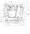
도 3은 본 개시의 실시 예에 따른 가습기의 단면도이다.
도 4는 본 개시의 실시 예에 따른 가습기 단면도의 확대도이다.
도 5는 본 개시의 실시 예에 따른 가습기의 일부이다.
도 6은 본 개시의 실시 예에 따른 가습기 절개도의 일부이다.
도 7은 본 개시의 실시 예에 따른 가습기의 일부이다.
도 8은 본 개시의 실시 예에 따른 가습기의 일부이다.
도 9는 본 개시의 실시 예에 따른 가습기의 하부 살균모듈에 관한 설명에 참조되는 도면이다.
도 10은 본 개시의 실시 예에 따른 가습기의 베이스 커버에 관한 설명에 참조되는 도면이다.
도 11과 도 12는 본 개시의 실시 예에 따른 가습기의 케이스와 베이스 커버의 결합에 관한 설명에 참조되는 도면이다.
도 13, 도 14a, 도 14b는 본 개시의 실시 예에 따른 가습기의 필터 안착에 관한 설명에 참조되는 도면이다.
도 15는 본 개시의 실시 예에 따른 가습기 일부의 단면도이다.
도 16은 본 개시의 실시 예에 따른 가습기 일부의 단면도이다.
도 17은 본 개시의 일 실시 예에 따른 가습 장치의 종단면도이다.
도 18은 본 개시의 일 실시 예에 따른 가습기의 개략도이다.FIG. 1 is a perspective view of a humidifier according to an embodiment of the present disclosure.
FIG. 2 is an exploded view of a humidifier according to an embodiment of the present disclosure.
FIG. 3 is a cross-sectional view of a humidifier according to an embodiment of the present disclosure.
FIG. 4 is an enlarged cross-sectional view of a humidifier according to an embodiment of the present disclosure.
FIG. 5 is a part of a humidifier according to an embodiment of the present disclosure.
FIG. 6 is a part of a cutaway view of a humidifier according to an embodiment of the present disclosure.
FIG. 7 is a part of a humidifier according to an embodiment of the present disclosure.
FIG. 8 is a part of a humidifier according to an embodiment of the present disclosure.
FIG. 9 is a drawing for reference in the description of the lower sterilizing module of the humidifier according to an embodiment of the present disclosure.
FIG. 10 is a drawing for reference in the description of a base cover of a humidifier according to an embodiment of the present disclosure.
FIGS. 11 and 12 are drawings for reference in the explanation of the combination of the case and the base cover of the humidifier according to an embodiment of the present disclosure.
FIG. 13, FIG. 14a, and FIG. 14b are drawings for reference in the description of filter mounting of a humidifier according to an embodiment of the present disclosure.
FIG. 15 is a cross-sectional view of a portion of a humidifier according to an embodiment of the present disclosure.
FIG. 16 is a cross-sectional view of a portion of a humidifier according to an embodiment of the present disclosure.
FIG. 17 is a cross-sectional view of a humidifying device according to one embodiment of the present disclosure.
FIG. 18 is a schematic diagram of a humidifier according to one embodiment of the present disclosure.
이하, 첨부된 도면을 참고하여 본 명세서에 개시된 실시 예를 상세하게 설명한다. 도면 부호에 관계없이 동일하거나 유사한 구성요소는 동일한 참조 번호를 부여하고 이에 대한 중복되는 설명은 생략하기로 한다.Hereinafter, embodiments disclosed in this specification will be described in detail with reference to the attached drawings. Regardless of the drawing symbols, identical or similar components are given the same reference numerals and redundant descriptions thereof will be omitted.
이하의 설명에서 사용되는 구성요소에 대한 접미사 “모듈” 및 “부”는 명세서 작성의 용이함만이 고려되어 부여되거나 혼용되는 것으로서, 그 자체로 서로 구별되는 의미 또는 역할을 갖는 것은 아니다.The suffixes “module” and “part” used for components in the following description are given or used interchangeably only for the convenience of writing the specification, and do not have distinct meanings or roles in themselves.
또한, 본 명세서에 개시된 실시 예를 설명함에 있어서 관련된 공지 기술에 대한 구체적인 설명이 본 명세서에 개시된 실시 예의 요지를 흐릴 수 있다고 판단되는 경우 그 상세한 설명을 생략한다. 또한, 첨부된 도면은 본 명세서에 개시된 실시 예를 쉽게 이해할 수 있도록 하기 위한 것일 뿐, 첨부된 도면에 의해 본 명세서에 개시된 기술적 사상이 제한되지 않으며, 본 개시의 사상 및 기술 범위에 포함되는 모든 변경, 균등물 내지 대체물을 포함하는 것으로 이해되어야 한다.In addition, when describing the embodiments disclosed in this specification, if it is determined that a detailed description of a related known technology may obscure the gist of the embodiments disclosed in this specification, the detailed description thereof will be omitted. In addition, the attached drawings are only intended to facilitate easy understanding of the embodiments disclosed in this specification, and the technical ideas disclosed in this specification are not limited by the attached drawings, and should be understood to include all modifications, equivalents, or substitutes included in the spirit and technical scope of the present disclosure.
제1, 제2 등과 같이 서수를 포함하는 용어는 다양한 구성요소들을 설명하는데 사용될 수 있지만, 상기 구성요소들은 상기 용어들에 의해 한정되지는 않는다. 상기 용어들은 하나의 구성요소를 다른 구성요소로부터 구별하는 목적으로만 사용된다.Terms including ordinal numbers, such as first, second, etc., may be used to describe various components, but the components are not limited by the terms. The terms are used only to distinguish one component from another.
어떤 구성요소가 다른 구성요소에 “연결되어” 있다거나 “접속되어” 있다고 언급된 때에는, 그 다른 구성요소에 직접적으로 연결되어 있거나 또는 접속되어 있을 수도 있지만, 중간에 다른 구성요소가 존재할 수도 있다고 이해되어야 할 것이다. 반면에, 어떤 구성요소가 다른 구성요소에 “직접 연결되어” 있다거나 “직접 접속되어” 있다고 언급된 때에는, 중간에 다른 구성요소가 존재하지 않는 것으로 이해되어야 할 것이다.When it is said that a component is “connected” or “connected” to another component, it should be understood that it may be directly connected or connected to that other component, but that there may be other components in between. On the other hand, when it is said that a component is “directly connected” or “connected” to another component, it should be understood that there are no other components in between.
단수의 표현은 문맥상 명백하게 다르게 뜻하지 않는 한, 복수의 표현을 포함한다.Singular expressions include plural expressions unless the context clearly indicates otherwise.
도 1을 참조하여, 가습기(1)를 설명한다.Referring to Fig. 1, a humidifier (1) is described.
도 1은 가습기(1)의 사시도이다.Figure 1 is a perspective view of a humidifier (1).
가습기(1)는 케이스(10)를 포함할 수 있다. 케이스(10)는 내부에 공간을 가질 수 있다. 케이스(10)는 원통형일 수 있다.The humidifier (1) may include a case (10). The case (10) may have a space inside. The case (10) may be cylindrical.
가습기(1)는 흡입구(11)를 포함할 수 있다. 흡입구(11)는 케이스(10)의 둘레를 따라 형성될 수 있다. 가습기(1) 외부의 공기는, 흡입구(11)를 통해 케이스(10) 내부로 유입될 수 있다.The humidifier (1) may include an intake port (11). The intake port (11) may be formed along the periphery of the case (10). Air outside the humidifier (1) may be introduced into the case (10) through the intake port (11).
가습기(1)는 토출구(12)를 포함할 수 있다. 토출구(12)는 케이스(10)의 상부에 형성될 수 있다. 케이스(10) 내로 흡입된 공기는, 토출구(12)를 통해 케이스(10) 외부로 토출될 수 있다.The humidifier (1) may include a discharge port (12). The discharge port (12) may be formed at the upper portion of the case (10). Air sucked into the case (10) may be discharged to the outside of the case (10) through the discharge port (12).
가습기(1)는 베이스(13)를 포함할 수 있다. 베이스(13)는 케이스(10)의 하측에 배치될 수 있다. 베이스(13)는 케이스(10)의 외경보다 큰 외경을 가질 수 있다.The humidifier (1) may include a base (13). The base (13) may be placed on the lower side of the case (10). The base (13) may have an outer diameter larger than the outer diameter of the case (10).
가습기(1)는 물통(20)을 포함할 수 있다. 물통(20)은 케이스(10) 내부에 배치될 수 있다. 물통(20) 내부에는 물이 저장되는 공간이 형성될 수 있다. 토출구(12)는 물통(20)의 반경방향 외측에 형성될 수 있다. 토출구(12)는 물통(20)을 둘러싸게 형성될 수 있다.The humidifier (1) may include a water tank (20). The water tank (20) may be placed inside the case (10). A space for storing water may be formed inside the water tank (20). The discharge port (12) may be formed on the radially outer side of the water tank (20). The discharge port (12) may be formed to surround the water tank (20).
도 2를 참조하여, 가습기(1)를 설명한다.Referring to Fig. 2, a humidifier (1) is described.
도 2는 가습기(1)를 분해하여 도시한 것이다.Figure 2 shows the humidifier (1) in an exploded view.
가습기(1)는 흡입그릴(14)을 포함할 수 있다. 흡입그릴(14)은 케이스(10)의 둘레를 따라 배치될 수 있다. 흡입그릴(14)은 흡입구(11)를 형성할 수 있다. 흡입그릴(14)은 원통형일 수 있다.The humidifier (1) may include a suction grill (14). The suction grill (14) may be arranged along the periphery of the case (10). The suction grill (14) may form a suction port (11). The suction grill (14) may be cylindrical.
가습기(1)는 토출그릴(15)을 포함할 수 있다. 토출그릴(15)은 케이스(10)의 상부에 배치될 수 있다. 토출그릴(15)은 토출구(12)를 형성할 수 있다. 토출그릴(15)은 환형일 수 있다.The humidifier (1) may include a discharge grill (15). The discharge grill (15) may be placed on the upper part of the case (10). The discharge grill (15) may form a discharge port (12). The discharge grill (15) may be annular.
가습기(1)는 제1 아우터케이스(16)를 포함할 수 있다. 제1 아우터케이스(16)는 원통형일 수 있다. 흡입그릴(14)은 제1 아우터케이스(16)에 탈착될 수 있다. 제1 아우터케이스(16)는 케이스(10)의 외형을 형성할 수 있다.The humidifier (1) may include a first outer case (16). The first outer case (16) may be cylindrical. The suction grill (14) may be detachable from the first outer case (16). The first outer case (16) may form the outer shape of the case (10).
가습기(1)는 제1 이너케이스(17)를 포함할 수 있다. 제1 이너케이스(17)는 원통형일 수 있다. 제1 이너케이스(17)는 제1 아우터케이스(16)의 반경방향 내측에 배치될 수 있다. 제1 아우터케이스(16)와 제1 이너케이스(17)는 반경방향으로 이격될 수 있다.The humidifier (1) may include a first inner case (17). The first inner case (17) may be cylindrical. The first inner case (17) may be arranged radially inwardly of the first outer case (16). The first outer case (16) and the first inner case (17) may be spaced apart radially.
가습기(1)는 제2 아우터케이스(19)를 포함할 수 있다. 제2 아우터케이스(19)는 원통형일 수 있다. 제2 아우터케이스(19)는 제1 아우터케이스(16)의 상측에 배치될 수 있다. 제2 아우터케이스(19)는 케이스(10)의 외형을 형성할 수 있다.The humidifier (1) may include a second outer case (19). The second outer case (19) may be cylindrical. The second outer case (19) may be placed on the upper side of the first outer case (16). The second outer case (19) may form the outer shape of the case (10).
가습기(1)는 제2 이너케이스(18)를 포함할 수 있다. 제2 이너케이스(18)는 원통형일 수 있다. 제2 이너케이스(18)는 제1 이너케이스(17)의 상측에 배치될 수 있다. 제2 이너케이스(18)는 제2 아우터케이스(19)의 반경방향 내측에 배치될 수 있다. 제2 아우터케이스(19)와 제2 이너케이스(18)는 반경방향으로 이격될 수 있다.The humidifier (1) may include a second inner case (18). The second inner case (18) may be cylindrical. The second inner case (18) may be arranged on the upper side of the first inner case (17). The second inner case (18) may be arranged radially inwardly of the second outer case (19). The second outer case (19) and the second inner case (18) may be spaced apart from each other in the radial direction.
제1 아우터케이스(16)와 제2 아우터케이스(19)는 분리가능하게 결합될 수 있다. 다만, 제1 아우터케이스(16)와 제2 아우터케이스(19)는 일체형일 수도 있다. 제1 아우터케이스(16)와 제2 아우터케이스(19)는 "아우터케이스"로 이름될 수 있다.The first outer case (16) and the second outer case (19) can be detachably combined. However, the first outer case (16) and the second outer case (19) may be integral. The first outer case (16) and the second outer case (19) may be named “outer cases.”
제1 이너케이스(17)와 제2 이너케이스(18)는 분리가능하게 결합될 수 있다. 다만, 제1 이너케이스(17)와 제2 이너케이스(18)는 일체형일 수도 있다. 제1 이너케이스(17)와 제2 이너케이스(18)는 "이너케이스"로 이름될 수 있다.The first inner case (17) and the second inner case (18) can be detachably combined. However, the first inner case (17) and the second inner case (18) may be integral. The first inner case (17) and the second inner case (18) may be named “inner cases.”
가습기(1)는 버킷(21)을 포함할 수 있다. 버킷(21)은 상측이 개구된 원통형일 수 있다. 버킷(21)은 내부에 물이 저장되는 공간을 가질 수 있다.The humidifier (1) may include a bucket (21). The bucket (21) may be cylindrical with an open top. The bucket (21) may have a space in which water is stored inside.
가습기(1)는 버킷하우징(22)을 포함할 수 있다. 버킷하우징(22)은 버킷(21)을 둘러쌀 수 있다. 버킷하우징(22)은 상측이 개구된 원통형일 수 있다. 버킷(21)은 버킷하우징(22)의 내측에 배치될 수 있다.The humidifier (1) may include a bucket housing (22). The bucket housing (22) may surround the bucket (21). The bucket housing (22) may have a cylindrical shape with an open upper side. The bucket (21) may be placed inside the bucket housing (22).
가습기(1)는 버킷커버(23)를 포함할 수 있다. 버킷커버(23)는 버킷(21)의 상측에 배치될 수 있다. 버킷커버(23)는 토출그릴(15)에 분리가능하게 결합될 수 있다.The humidifier (1) may include a bucket cover (23). The bucket cover (23) may be placed on the upper side of the bucket (21). The bucket cover (23) may be detachably connected to the discharge grill (15).
물통(20)은 버킷(21), 버킷하우징(22) 및 버킷커버(23)를 포함할 수 있다. 물통(20)은 이너케이스(18)의 내측에 배치될 수 있다. 물통(20)과 이너케이스(18)는 반경방향으로 이격될 수 있다.The water tank (20) may include a bucket (21), a bucket housing (22), and a bucket cover (23). The water tank (20) may be placed inside the inner case (18). The water tank (20) and the inner case (18) may be spaced apart in the radial direction.
도 3을 참조하여, 가습기(1)를 설명한다.Referring to Fig. 3, a humidifier (1) is described.
도 3은 가습기(1)의 수직방향 단면도이다.Figure 3 is a vertical cross-sectional view of the humidifier (1).
가습기(1)는 필터(31)를 포함할 수 있다. 필터(31)는 흡입그릴(14)의 내측에 배치될 수 있다. 필터(31)는 원통형일 수 있다.The humidifier (1) may include a filter (31). The filter (31) may be placed inside the suction grill (14). The filter (31) may be cylindrical.
가습기(1)는 팬(32)을 포함할 수 있다. 팬(32)은 필터(31)의 상측에 배치될 수 있다. 팬(32)은 흡입그릴(14)의 내측에 배치될 수 있다.The humidifier (1) may include a fan (32). The fan (32) may be placed above the filter (31). The fan (32) may be placed inside the suction grill (14).
가습기(1)는 팬모터(33)를 포함할 수 있다. 팬모터(33)는 팬(32)을 회전시킬 수 있다. 팬모터(33)는 팬(32)의 상측에 배치될 수 있다.The humidifier (1) may include a fan motor (33). The fan motor (33) may rotate the fan (32). The fan motor (33) may be placed above the fan (32).
가습기(1)는 제어부(34)를 포함할 수 있다. 제어부(34)는 케이스(10)의 내측에 배치될 수 있다. 제어부(34)는 팬모터(33)와 가습어셈블리(40) 사이에 배치될 수 있다. 제어부(34)는 팬모터(33)와 가습어셈블리(40)의 구동을 제어할 수 있다. 제어부(34)는 하나 이상의 프로세서를 포함할 수 있다. 제어부(34)는 하나 이상의 PCB기판을 포함할 수 있다.The humidifier (1) may include a control unit (34). The control unit (34) may be arranged inside the case (10). The control unit (34) may be arranged between the fan motor (33) and the humidifying assembly (40). The control unit (34) may control the operation of the fan motor (33) and the humidifying assembly (40). The control unit (34) may include one or more processors. The control unit (34) may include one or more PCB boards.
가습기(1)는 가습어셈블리(40)를 포함할 수 있다. 가습어셈블리(40)는 케이스(10) 내부에 배치될 수 있다. 가습어셈블리(40)는 물통(20)과 팬(32) 사이에 배치될 수 있다. 가습어셈블리(40)는 물통(20)으로부터 공급된 물을 미립화시켜, 토출구(12)로 공급할 수 있다. 팬(32)에 의해 송풍된 공기의 일부는, 가습어셈블리(40)로 유입될 수 있다.The humidifier (1) may include a humidifying assembly (40). The humidifying assembly (40) may be placed inside the case (10). The humidifying assembly (40) may be placed between the water tank (20) and the fan (32). The humidifying assembly (40) may atomize water supplied from the water tank (20) and supply it to the discharge port (12). A portion of the air blown by the fan (32) may be introduced into the humidifying assembly (40).
토출그릴(15)은 물통(20)과 아우터케이스(19) 사이에 배치될 수 있다. 이너케이스(18)는 물통(20)과 아우터케이스(19) 사이에 배치될 수 있다. 토출그릴(15)은 이너케이스(18)의 상측에 배치될 수 있다.The discharge grill (15) can be placed between the water tank (20) and the outer case (19). The inner case (18) can be placed between the water tank (20) and the outer case (19). The discharge grill (15) can be placed on the upper side of the inner case (18).
토출구(12)는 제1 토출구(121)를 포함할 수 있다. 제1 토출구(121)는 아우터케이스(19)와 이너케이스(18) 사이에 형성될 수 있다. 팬(32)에 의해 송풍된 공기는, 제1 토출구(121)를 통해 상방으로 유동할 수 있다. 제1 토출구(121)는 환형으로 연장될 수 있다. 제1 토출구(121)는 "송풍유로"로 이름될 수 있다. 또한, 제1 토출구(121)는, 제1 토출 유로(1000a)와 제1 토출구(12a)로 구성될 수 있다(도 18 참조).The outlet (12) may include a first outlet (121). The first outlet (121) may be formed between the outer case (19) and the inner case (18). Air blown by the fan (32) may flow upward through the first outlet (121). The first outlet (121) may be extended in an annular shape. The first outlet (121) may be called a “blowing path.” In addition, the first outlet (121) may be composed of a first discharge path (1000a) and a first outlet (12a) (see FIG. 18).
토출구(12)는 제2 토출구(122)를 포함할 수 있다. 제2 토출구(122)는 이너케이스(18)와 물통(20) 사이에 형성될 수 있다. 가습어셈블리(40)를 통과한 가습공기는, 제2 토출구(122)를 통해 상방으로 유동할 수 있다. 제2 토출구(122)는 환형으로 연장될 수 있다. 제2 토출구(122)는 "가습유로"로 이름될 수 있다. 또한, 제2 토출구(122)는, 제2 토출 유로(1000b)와 제2 토출구(12b)로 구성될 수 있다(도 18 참조).The outlet (12) may include a second outlet (122). The second outlet (122) may be formed between the inner case (18) and the water tank (20). Humidified air passing through the humidifying assembly (40) may flow upward through the second outlet (122). The second outlet (122) may be extended in an annular shape. The second outlet (122) may be referred to as a “humidifying path.” In addition, the second outlet (122) may be composed of a second outlet path (1000b) and a second outlet (12b) (see FIG. 18).
토출구(12)는 혼합토출구(123)를 포함할 수 있다. 혼합토출구(123)는 제1 토출구(121) 및 제2 토출구(122)의 상측에 형성될 수 있다. 혼합토출구(123)는 토출그릴(15)에 형성될 수 있다. 혼합토출구(123)는 환형으로 연장될 수 있다. 혼합토출구(123)는 아우터케이스(19)와 버킷커버(23) 사이에 형성될 수 있다. 제1 토출구(121)에 유동하는 공기 및 제2 토출구(122)에 유동하는 공기는, 혼합토출구(123)에서 섞일 수 있다.The outlet (12) may include a mixing outlet (123). The mixing outlet (123) may be formed above the first outlet (121) and the second outlet (122). The mixing outlet (123) may be formed in the outlet grill (15). The mixing outlet (123) may be extended in an annular shape. The mixing outlet (123) may be formed between the outer case (19) and the bucket cover (23). The air flowing in the first outlet (121) and the air flowing in the second outlet (122) may be mixed in the mixing outlet (123).
토출구(12)는 제1 토출구(121), 제2 토출구(122) 및 혼합토출구(123)를 포함하는 개념일 수 있다. 다만, 상술한 구성요소(121, 122, 123)과는 구분되는 케이스(10) 외부를 향해 개구된 공간을 의미할 수도 있다. 토출구(12)는 케이스(10) 상측을 향해 개구될 수 있다. 토출구(12)는 토출그릴(15)에 형성될 수 있다. 토출구(12)는 물통(20)을 둘러싸게 형성될 수 있다. 팬(32)에 의해 송풍된 공기는 토출구(12)를 통해 유동할 수 있다.The discharge port (12) may be a concept including a first discharge port (121), a second discharge port (122), and a mixed discharge port (123). However, it may also mean a space opened toward the outside of the case (10) that is distinct from the above-described components (121, 122, 123). The discharge port (12) may be opened toward the upper side of the case (10). The discharge port (12) may be formed in the discharge grill (15). The discharge port (12) may be formed to surround the water tank (20). Air blown by the fan (32) may flow through the discharge port (12).
송풍유로(121)는 토출구(12)와 연결될 수 있다. 가습유로(122)는 토출구(12)와 연결될 수 있다. 송풍유로(121) 내의 공기와 가습유로(122) 내의 공기는, 토출구(12)에서 혼합될 수 있다.The blower passage (121) can be connected to the discharge port (12). The humidifier passage (122) can be connected to the discharge port (12). The air in the blower passage (121) and the air in the humidifier passage (122) can be mixed at the discharge port (12).
흡입그릴(14)을 통해 케이스(10) 내로 유입된 공기는, 필터(31)를 통과하여 팬(32)에 의해 상방으로 송풍될 수 있다. 팬(32)에 의해 상방으로 송풍된 공기의 일부는 가습어셈블리(40)로 유입될 수 있고, 나머지는 제1 토출구(121)를 통해 상방으로 유동할 수 있다. 가습어셈블리(40)로 유입된 공기는, 미립화된 물방울을 함유한 상태로 제2 토출구(122)를 통해 상방으로 유동할 수 있다. 제1 토출구(121)를 통해 유동하는 공기와 제2 토출구(122)를 통해 유동하는 가습공기는, 혼합토출구(123)에서 합류하여 가습기(1)의 상방으로 토출될 수 있다.Air drawn into the case (10) through the suction grill (14) can pass through the filter (31) and be blown upward by the fan (32). A portion of the air blown upward by the fan (32) can be drawn into the humidifying assembly (40), and the remainder can flow upward through the first discharge port (121). The air drawn into the humidifying assembly (40) can flow upward through the second discharge port (122) while containing atomized water droplets. The air flowing through the first discharge port (121) and the humidified air flowing through the second discharge port (122) can be combined at the mixing discharge port (123) and discharged upward from the humidifier (1).
도 4를 참조하여, 가습기(1)를 설명한다.Referring to Fig. 4, a humidifier (1) is described.
도 4는 가습기(1)를 수직방향으로 절개한 단면도의 일부이다.Fig. 4 is a part of a cross-sectional view taken vertically through the humidifier (1).
가습기(1)는 가습어셈블리(40)를 포함할 수 있다. 가습어셈블리(40)는 물통(20)의 하측에 배치될 수 있다. 가습어셈블리(40)에서 생성된 가습공기는, 상방으로 토출될 수 있다.The humidifier (1) may include a humidifying assembly (40). The humidifying assembly (40) may be placed on the lower side of the water tank (20). Humidified air generated in the humidifying assembly (40) may be discharged upward.
가습어셈블리(40)는 가열장치(41)를 포함할 수 있다. 가열장치(41)는 유입된 물 및 공기를 가열할 수 있다.The humidifying assembly (40) may include a heating device (41). The heating device (41) may heat the introduced water and air.
가열장치(41)는 가열챔버(411)를 포함할 수 있다. 가열챔버(411)는 내부에 공간을 가질 수 있다. 물통(20) 내부에 저장된 물은, 가열챔버(411) 내로 유입될 수 있다.The heating device (41) may include a heating chamber (411). The heating chamber (411) may have a space inside. Water stored inside the water tank (20) may be introduced into the heating chamber (411).
가열장치(41)는 히터(412)를 포함할 수 있다. 히터(412)는 가열챔버(411)의 하측에 결합될 수 있다. 히터(412)는 가열챔버(411) 내부로 열을 가할 수 있다. 히터(412)는 가열챔버(411) 내로 유입된 물과 공기를 가열할 수 있다.The heating device (41) may include a heater (412). The heater (412) may be coupled to the lower side of the heating chamber (411). The heater (412) may apply heat to the inside of the heating chamber (411). The heater (412) may heat water and air introduced into the heating chamber (411).
가습어셈블리(40)는 가습장치(42)를 포함할 수 있다. 가습장치(42)는 유입된 물을 액적상태로 변화시킬 수 있다. 가습장치(42)는 유입된 물을 미립화된 물방울로 변화시켜, 상방으로 토출할 수 있다.The humidifying assembly (40) may include a humidifying device (42). The humidifying device (42) may change the introduced water into a liquid droplet state. The humidifying device (42) may change the introduced water into atomized water droplets and discharge them upward.
가습장치(42)는 가습챔버(421)를 포함할 수 있다. 가습챔버(421)는 내부에 공간을 가질 수 있다. 가열장치(41)에서 가열된 물은, 가습챔버(421)로 유입될 수 있다.The humidifying device (42) may include a humidifying chamber (421). The humidifying chamber (421) may have a space inside. Water heated in the heating device (41) may flow into the humidifying chamber (421).
가습장치(42)는 초음파진동자(422)를 포함할 수 있다. 초음파진동자(422)는 가습챔버(421)의 하측에 결합될 수 있다. 초음파진동자(422)는 초음파를 사용하여 진동을 발생시킬 수 있다. 초음파진동자(422)의 구동에 의해, 가습챔버(421) 내의 물은 미립화된 물방울로 변화될 수 있다. 가습장치(42)는 기 공지된 초음파식 가습기의 원리가 동일하게 적용될 수 있다.The humidifier (42) may include an ultrasonic vibrator (422). The ultrasonic vibrator (422) may be coupled to the lower side of the humidifying chamber (421). The ultrasonic vibrator (422) may generate vibrations using ultrasonic waves. By driving the ultrasonic vibrator (422), water in the humidifying chamber (421) may be changed into atomized water droplets. The humidifying device (42) may be applied with the same principle as a known ultrasonic humidifier.
가습어셈블리(40)는 밸브하우징(43)을 포함할 수 있다. 밸브하우징(43)은 가열장치(41)와 결합될 수 있다. 밸브하우징(43)은 가열챔버(411) 내에 배치될 수 있다.The humidifying assembly (40) may include a valve housing (43). The valve housing (43) may be coupled to a heating device (41). The valve housing (43) may be placed within a heating chamber (411).
가습어셈블리(40)는 밸브(44)를 포함할 수 있다. 밸브(44)는 플로팅밸브일 수 있다. 밸브(44)는 밸브하우징(43) 내부에 이동가능하게 배치될 수 있다. 밸브(44)는 밸브하우징(43) 내에서 상하방향으로 이동되어, 가열챔버(411) 내로 선택적으로 물을 공급할 수 있다.The humidifying assembly (40) may include a valve (44). The valve (44) may be a floating valve. The valve (44) may be movably arranged within a valve housing (43). The valve (44) may be moved up and down within the valve housing (43) to selectively supply water into the heating chamber (411).
가습어셈블리(40)는 인렛(45)을 포함할 수 있다. 인렛(45)은 가습장치(42)와 연결될 수 있다. 인렛(45)은 가습챔버(421) 내부와 연결될 수 있다. 팬(32)(도 3참조)에 의해 송풍된 공기의 일부는, 인렛(45)을 통해 가습챔버(421) 내부로 유입될 수 있다.The humidifying assembly (40) may include an inlet (45). The inlet (45) may be connected to a humidifying device (42). The inlet (45) may be connected to the inside of a humidifying chamber (421). A portion of the air blown by the fan (32) (see FIG. 3) may be introduced into the inside of the humidifying chamber (421) through the inlet (45).
가습어셈블리(40)는 아웃렛(46)을 포함할 수 있다. 아웃렛(46)은 가습장치(42)와 연결될 수 있다. 아웃렛(46)은 가습챔버(421) 내부를 향해 돌출될 수 있다. 가습장치(42)에서 생성된 미립자의 물방울은, 아웃렛(46)을 통해 상방으로 유동할 수 있다.The humidifying assembly (40) may include an outlet (46). The outlet (46) may be connected to a humidifying device (42). The outlet (46) may protrude toward the inside of the humidifying chamber (421). Water droplets of fine particles generated in the humidifying device (42) may flow upward through the outlet (46).
가습어셈블리(40)는 커넥터(47)를 포함할 수 있다. 커넥터(47)는 가열장치(41)와 가습장치(42)를 연결할 수 있다. 커넥터(47)는 가열챔버(411)와 가습챔버(421)를 연결할 수 있다. 커넥터(47)는 아웃렛(46)과 마주할 수 있다.The humidifying assembly (40) may include a connector (47). The connector (47) may connect the heating device (41) and the humidifying device (42). The connector (47) may connect the heating chamber (411) and the humidifying chamber (421). The connector (47) may face the outlet (46).
가습어셈블리(40)는 공급포트(48)를 포함할 수 있다. 공급포트(48)는 물통(20)과 가열장치(41)를 연결할 수 있다. 물통(20) 내부의 물은, 공급포트(48)를 통해 가열장치(41) 내로 유입될 수 있다.The humidifying assembly (40) may include a supply port (48). The supply port (48) may connect a water tank (20) and a heating device (41). Water inside the water tank (20) may flow into the heating device (41) through the supply port (48).
공급포트(48)는 제1 공급포트(481)를 포함할 수 있다. 제1 공급포트(481)는 물통(20)과 연결될 수 있다. 제1 공급포트(481)는 버킷하우징(22)의 하부와 연결될 수 있다.The supply port (48) may include a first supply port (481). The first supply port (481) may be connected to a water tank (20). The first supply port (481) may be connected to the lower portion of the bucket housing (22).
물통(20)은 배출포트(24)를 포함할 수 있다. 배출포트(24)는 물통(20)의 하부에 배치될 수 있다. 배출포트(24)는 제1 공급포트(481)와 연결될 수 있다.The water tank (20) may include a discharge port (24). The discharge port (24) may be located at the bottom of the water tank (20). The discharge port (24) may be connected to the first supply port (481).
공급포트(48)는 제2 공급포트(482)를 포함할 수 있다. 제2 공급포트(482)는 제1 공급포트(481)와 밸브하우징(43)을 연결할 수 있다. 제1 공급포트(481)로 유입된 물은, 제2 공급포트(482)를 통해 밸브하우징(43) 내로 유입될 수 있다.The supply port (48) may include a second supply port (482). The second supply port (482) may connect the first supply port (481) and the valve housing (43). Water flowing into the first supply port (481) may flow into the valve housing (43) through the second supply port (482).
가습어셈블리(40)는 연결관(49)을 포함할 수 있다. 연결관(49)은 가열장치(41)와 가습장치(42)를 연결할 수 있다. 연결관(49)은 가열챔버(411)와 가습챔버(421)를 연결할 수 있다. 가열챔버(411) 내의 물은, 연결관(49)을 통해 가습챔버(421) 내로 유입될 수 있다.The humidifying assembly (40) may include a connecting pipe (49). The connecting pipe (49) may connect the heating device (41) and the humidifying device (42). The connecting pipe (49) may connect the heating chamber (411) and the humidifying chamber (421). Water in the heating chamber (411) may flow into the humidifying chamber (421) through the connecting pipe (49).
아우터케이스(16)와 이너케이스(17) 사이에 유동하는 공기 중 일부는, 인렛(45)을 통해 가습장치(42)로 유입될 수 있다. 가습장치(42)로 유입된 공기는, 가습장치(42) 내에서 생성된 물방울을 함유한 상태로 아웃렛(46)을 통해 상방으로 유동할 수 있다. 아웃렛(46)을 통해 상방으로 유동하는 공기는, 물통(20)과 이너케이스(18) 사이에서 상방으로 유동할 수 있다.Some of the air flowing between the outer case (16) and the inner case (17) may flow into the humidifier (42) through the inlet (45). The air flowing into the humidifier (42) may flow upward through the outlet (46) while containing water droplets generated within the humidifier (42). The air flowing upward through the outlet (46) may flow upward between the water tank (20) and the inner case (18).
물통(20) 내의 물은, 공급포트(48)를 통해 밸브하우징(43) 내로 유입될 수 있다. 밸브하우징(43) 내의 물은, 밸브(44)의 이동에 의해, 가열장치(41) 내로 유입될 수 있다. 가열장치(41) 내로 유입된 물은, 히터(412)에 의해 가열될 수 있다. 가열챔버(411) 내에서 가열된 물은, 연결관(49)을 통해 가습챔버(421) 내로 유입될 수 있다. 가습챔버(421) 내로 유입된 물은, 초음파진동자(422)에 의해 미립자의 물방울로 변화될 수 있다. 미립자의 물방울은, 인렛(45)을 통해 유입된 공기와 함께 아웃렛(46)을 통해 상방으로 유동할 수 있다.The water in the water tank (20) can flow into the valve housing (43) through the supply port (48). The water in the valve housing (43) can flow into the heating device (41) by the movement of the valve (44). The water that flows into the heating device (41) can be heated by the heater (412). The water heated in the heating chamber (411) can flow into the humidifying chamber (421) through the connecting pipe (49). The water that flows into the humidifying chamber (421) can be changed into fine particle water droplets by the ultrasonic vibrator (422). The fine particle water droplets can flow upward through the outlet (46) together with the air that flows in through the inlet (45).
도 5를 참조하여, 가습기(1)를 설명한다.Referring to Fig. 5, a humidifier (1) is described.
도 5는 제1 아우터케이스(16)를 제거한 상태의 가습기(1)를 도시한 것이다.Figure 5 illustrates a humidifier (1) with the first outer case (16) removed.
가습기(1)는 필터장착공간(311)을 포함할 수 있다. 필터장착공간(311)은 흡입그릴(14)의 내측에 형성될 수 있다. 필터(31)(도 3참조)는, 필터장착공간(311)에 배치될 수 있다. 흡입그릴(14)을 통해 유입된 공기는 필터장착공간(311)을 통과하여, 상방으로 유동할 수 있다.The humidifier (1) may include a filter mounting space (311). The filter mounting space (311) may be formed on the inside of the suction grill (14). A filter (31) (see FIG. 3) may be placed in the filter mounting space (311). Air drawn in through the suction grill (14) may pass through the filter mounting space (311) and flow upward.
가습기(1)는 팬하우징(321)을 포함할 수 있다. 팬(32)(도 3참조)은 팬하우징(321) 내부에 배치될 수 있다. 팬하우징(321)은 필터(31)(도 3참조)의 상측에 배치될 수 있다.The humidifier (1) may include a fan housing (321). The fan (32) (see FIG. 3) may be placed inside the fan housing (321). The fan housing (321) may be placed above the filter (31) (see FIG. 3).
가습기(1)는 하우징상부(322)를 포함할 수 있다. 하우징상부(322)는 팬하우징(321)의 상부를 형성할 수 있다. 하우징상부(322)는 이너케이스(17)의 반경방향 외측에 이격될 수 있다. 팬(32)(도 3참조)에 의해 송풍된 공기는, 이너케이스(17)와 하우징상부(322) 사이에 형성된 공간을 통해 상방으로 유동할 수 있다.The humidifier (1) may include a housing upper portion (322). The housing upper portion (322) may form an upper portion of a fan housing (321). The housing upper portion (322) may be spaced radially outside the inner case (17). Air blown by the fan (32) (see FIG. 3) may flow upward through a space formed between the inner case (17) and the housing upper portion (322).
가습기(1)는 가이드(171)를 포함할 수 있다. 가이드(171)는 이너케이스(17)의 반경방향 외측으로 돌출될 수 있다. 가이드(171)는 인렛(45)과 팬하우징(321) 사이에 배치될 수 있다. 가이드(171)는 이너케이스(17)의 둘레방향으로 이격되게 복수개가 배치될 수 있다. 복수의 가이드(171) 사이공간은, 인렛(45)과 상하로 마주할 수 있다. 복수의 가이드(171) 사이공간은, 하우징상부(322)와 상하로 마주할 수 있다.The humidifier (1) may include a guide (171). The guide (171) may protrude radially outwardly from the inner case (17). The guide (171) may be arranged between the inlet (45) and the fan housing (321). A plurality of guides (171) may be arranged spaced apart from each other in the circumferential direction of the inner case (17). The spaces between the plurality of guides (171) may face the inlet (45) vertically. The spaces between the plurality of guides (171) may face the upper part of the housing (322) vertically.
가습기(1)는 이너그릴(59)을 포함할 수 있다. 이너그릴(59)은 가습어셈블리(40)의 상측에 배치될 수 있다. 이너그릴(59)은 이너케이스(17)의 반경방향 외측에 배치될 수 있다. 이너그릴(59)은 아우터케이스(19)와 결합될 수 있다.The humidifier (1) may include an inner grill (59). The inner grill (59) may be arranged on the upper side of the humidifying assembly (40). The inner grill (59) may be arranged on the radially outer side of the inner case (17). The inner grill (59) may be combined with the outer case (19).
팬(32)(도 3참조)에 의해 송풍된 공기의 일부는, 인렛(45)으로 유입될 수 있다. 팬(32)에 의해 송풍된 공기의 일부는, 복수의 가이드(171) 사이공간을 통해 인렛(45)으로 유입될 수 있다. 인렛(45)을 통해 가습어셈블리(40)로 유입된 공기는, 미립자의 물방울을 함유한 상태로, 토출구(12)를 통해 토출될 수 있다.A portion of the air blown by the fan (32) (see Fig. 3) may be introduced into the inlet (45). A portion of the air blown by the fan (32) may be introduced into the inlet (45) through the space between the plurality of guides (171). The air introduced into the humidifying assembly (40) through the inlet (45) may be discharged through the discharge port (12) in a state containing fine particle water droplets.
서포터(352)는 인렛(45)에 고정될 수 있다. 서포터(352)는 팬장치(351)와 인렛(45)을 연결할 수 있다.The supporter (352) can be fixed to the inlet (45). The supporter (352) can connect the fan device (351) and the inlet (45).
팬(32)에 의해 송풍된 공기의 일부는, 아우터케이스(16)(도 3참조)와 이너케이스(17) 사이공간을 통해 상방으로 유동하여, 이너그릴(59)을 통과할 수 있다. 이너그릴(59)을 통과한 공기는 상방으로 유동하여, 토출구(12)로 토출될 수 있다.A portion of the air blown by the fan (32) can flow upward through the space between the outer case (16) (see FIG. 3) and the inner case (17) and pass through the inner grill (59). The air that passes through the inner grill (59) can flow upward and be discharged through the discharge port (12).
도 6을 참조하여, 가습기(1)를 설명한다.Referring to Fig. 6, a humidifier (1) is described.
도 6은 가습기(1)를 수직방향으로 절개하여, 일부분을 비스듬히 도시한 것이다.Figure 6 is a view of a humidifier (1) cut vertically and a portion thereof is drawn obliquely.
아우터케이스(16)와 이너케이스(17) 사이에서 상방으로 유동하는 공기의 일부는, 인렛(45)으로 유입될 수 있다.A portion of the air flowing upward between the outer case (16) and the inner case (17) can be introduced into the inlet (45).
가이드(171)는 인렛(45)과 상하로 마주할 수 있다.The guide (171) can face the inlet (45) from above and below.
인렛(45)을 통해 가습챔버(421) 내로 유입된 공기는, 초음파진동자(422)의 구동에 의해 생성된 물방울과 혼합될 수 있다. 물방울과 혼합된 가습공기는, 아웃렛(46)을 통해 상방으로 유동할 수 있다.Air introduced into the humidifying chamber (421) through the inlet (45) can be mixed with water droplets generated by the operation of the ultrasonic vibrator (422). The humidified air mixed with the water droplets can flow upward through the outlet (46).
가습챔버(421)는 가열챔버(411)와 연통될 수 있다. 커넥터(47)는 가습챔버(421)와 가열챔버(411)를 연결할 수 있다.The humidifying chamber (421) can be communicated with the heating chamber (411). The connector (47) can connect the humidifying chamber (421) and the heating chamber (411).
가열챔버(411) 내의 공기는 가습챔버(421) 내로 유입된 공기와 혼합되어, 아웃렛(46)으로 빠져나갈 수 있다. 가열챔버(411) 내로 유입된 물의 일부는 증발되어 수증기의 형태로 가습챔버(421) 내로 유입될 수 있다. 가열챔버(411)에서 생성된 수증기는 가습챔버(421) 내의 가습공기와 혼합되어, 아웃렛(46)으로 빠져나갈 수 있다.The air inside the heating chamber (411) can be mixed with the air introduced into the humidifying chamber (421) and can be discharged through the outlet (46). Some of the water introduced into the heating chamber (411) can be evaporated and introduced into the humidifying chamber (421) in the form of water vapor. The water vapor generated in the heating chamber (411) can be mixed with the humidified air inside the humidifying chamber (421) and can be discharged through the outlet (46).
가습챔버(421)로부터 아웃렛(46)을 통해 상방으로 유동하는 공기는, 물통(20)과 이너케이스(18) 사이로 유입될 수 있다. 아웃렛(46)으로 토출된 가습공기는, 물통(20)과 이너케이스(18) 사이에서 상방으로 유동할 수 있다.Air flowing upward from the humidifying chamber (421) through the outlet (46) can be introduced between the water tank (20) and the inner case (18). Humidified air discharged through the outlet (46) can flow upward between the water tank (20) and the inner case (18).
가습기(1)는 이너커버(50)를 포함할 수 있다. 이너커버(50)는 아웃렛(46)과 연결될 수 있다. 이너커버(50)는 물통(20)과 가습어셈블리(40) 사이에 배치될 수 있다. 아웃렛(46)을 통해 유동하는 공기는, 이너커버(50)의 상측으로 유동할 수 있다.The humidifier (1) may include an inner cover (50). The inner cover (50) may be connected to an outlet (46). The inner cover (50) may be placed between the water tank (20) and the humidifying assembly (40). Air flowing through the outlet (46) may flow to the upper side of the inner cover (50).
물통(20)은 가이드림(25)을 포함할 수 있다. 가이드림(25)은 물통(20)의 둘레를 따라 연장될 수 있다. 가이드림(25)은 아웃렛(46)의 상측에 이격될 수 있다. 가이드림(25)은 이너커버(50)의 상측에 이격될 수 있다. 아웃렛(46)을 통해 유동하는 공기는, 가이드림(25)에 의해 물통(20)의 둘레방향으로 확산될 수 있다. 물통(20)의 둘레방향으로 확산된 가습공기는, 물통(20)과 이너케이스(18) 사이에서 상방으로 유동할 수 있다.The water tank (20) may include a guide rim (25). The guide rim (25) may extend along the circumference of the water tank (20). The guide rim (25) may be spaced from the upper side of the outlet (46). The guide rim (25) may be spaced from the upper side of the inner cover (50). Air flowing through the outlet (46) may be diffused in the circumferential direction of the water tank (20) by the guide rim (25). The humidified air diffused in the circumferential direction of the water tank (20) may flow upward between the water tank (20) and the inner case (18).
아우터케이스(16)와 이너케이스(17) 사이에 유동하는 공기의 일부는, 이너그릴(59)을 통해 상방으로 유동할 수 있다. 이너그릴(59)은 아우터케이스(19)와 이너케이스(18) 사이에 배치될 수 있다. 이너그릴(59)을 통과한 공기는, 아우터케이스(19)와 이너케이스(18) 사이에서 상방으로 유동할 수 있다.A portion of the air flowing between the outer case (16) and the inner case (17) can flow upward through the inner grill (59). The inner grill (59) can be placed between the outer case (19) and the inner case (18). The air passing through the inner grill (59) can flow upward between the outer case (19) and the inner case (18).
도 7을 참조하여, 가습기(1)를 설명한다.Referring to Fig. 7, a humidifier (1) is described.
도 7은 가습어셈블리(40)의 일부를 분리하여 도시한 것이다.Figure 7 is a diagram showing a portion of the humidifier assembly (40) in isolation.
가습어셈블리(40)는 가습장치(42)를 포함할 수 있다. 가습장치(42)는 분무를 생성할 수 있다. 가습장치(42)는 가습챔버(421) 및 초음파진동자(422)를 포함할 수 있다.The humidifying assembly (40) may include a humidifying device (42). The humidifying device (42) may generate a mist. The humidifying device (42) may include a humidifying chamber (421) and an ultrasonic vibrator (422).
가습어셈블리(40)는 바디(401)를 포함할 수 있다. 바디(401)는 상측이 개구된 원통형일 수 있다. 가열장치(41)(도 4 참조)와 가습장치(42)는 바디(401)와 결합될 수 있다. 가열장치(41)(도 4 참조)와 가습장치(42)는 바디(401)의 하측에 결합될 수 있다.The humidifying assembly (40) may include a body (401). The body (401) may be cylindrical with an open upper side. A heating device (41) (see FIG. 4) and a humidifying device (42) may be coupled to the body (401). The heating device (41) (see FIG. 4) and the humidifying device (42) may be coupled to the lower side of the body (401).
가습어셈블리(40)는 아웃렛(46)을 포함할 수 있다. 인렛(45)을 통해 가습장치(42) 내로 유입된 공기는 분무를 함유한 상태로 아웃렛(46)으로 유동할 수 있다. 아웃렛(46)은 바디(401)에 결합될 수 있다. 아웃렛(46)은 가습장치(42)의 상부에 결합될 수 있다.The humidifying assembly (40) may include an outlet (46). Air introduced into the humidifying device (42) through the inlet (45) may flow to the outlet (46) in a state containing spray. The outlet (46) may be coupled to the body (401). The outlet (46) may be coupled to the upper portion of the humidifying device (42).
아웃렛(46)은 아웃렛바디(461)를 포함할 수 있다. 아웃렛바디(461)는 바디(401)에 결합될 수 있다. 아웃렛바디(461)는 가습챔버(421)의 내측으로 삽입될 수 있다.The outlet (46) may include an outlet body (461). The outlet body (461) may be coupled to the body (401). The outlet body (461) may be inserted into the inside of the humidifying chamber (421).
아웃렛(46)은 분무토출구(462)를 포함할 수 있다. 분무토출구(462)는 아웃렛바디(461)로부터 상측으로 돌출될 수 있다. 가습장치(42)에서 생성된 분무는, 분무토출구(462)를 통해 상방으로 유동할 수 있다.The outlet (46) may include a spray outlet (462). The spray outlet (462) may protrude upward from the outlet body (461). The spray generated in the humidifier (42) may flow upward through the spray outlet (462).
아웃렛(46)은 분무유입구(463)를 포함할 수 있다. 분무유입구(463)는 아웃렛바디(461)로부터 하측으로 돌출될 수 있다. 분무유입구(463)는 가습챔버(421)의 내측을 향해 연장될 수 있다. 가습장치(42)에서 생성된 분무는, 분무유입구(463)를 통해 분무토출구(462)를 향해 유동할 수 있다.The outlet (46) may include a spray inlet (463). The spray inlet (463) may protrude downward from the outlet body (461). The spray inlet (463) may extend toward the inside of the humidifying chamber (421). The spray generated in the humidifying device (42) may flow toward the spray outlet (462) through the spray inlet (463).
아웃렛(46)은 커넥터결합부(464)를 포함할 수 있다. 커넥터결합부(464)는 가열장치(41)(도 4 참조)를 향해 연장될 수 있다. 커넥터결합부(464)는 커넥터(47)(도 4 참조)와 결합될 수 있다.The outlet (46) may include a connector coupling portion (464). The connector coupling portion (464) may extend toward the heating device (41) (see FIG. 4). The connector coupling portion (464) may be coupled with a connector (47) (see FIG. 4).
아웃렛(46)은 인렛커버(465)를 포함할 수 있다. 인렛커버(465)는 인렛(45)의 상측에 배치될 수 있다. 인렛커버(465)는 인렛(45)의 상부를 둘러쌀 수 있다.The outlet (46) may include an inlet cover (465). The inlet cover (465) may be positioned on the upper side of the inlet (45). The inlet cover (465) may surround the upper part of the inlet (45).
아웃렛(46)은 서포터(466)를 포함할 수 있다. 서포터(466)는 아웃렛바디(461)로부터 하측으로 연장될 수 있다. 서포터(466)는 가습챔버(421)의 내측에 배치될 수 있다. 서포터(466)는 가습챔버(421)의 측벽과 마주할 수 있다.The outlet (46) may include a supporter (466). The supporter (466) may extend downward from the outlet body (461). The supporter (466) may be arranged inside the humidifying chamber (421). The supporter (466) may face a side wall of the humidifying chamber (421).
도 8을 참조하여, 가습기(1)를 설명한다.Referring to Fig. 8, a humidifier (1) is described.
도 8은 가습어셈블리(40)의 일부를 분리하여 상측에서 바라본 것이다.Figure 8 is a top view of a portion of the humidifier assembly (40) separated from the rest.
바디(401)는 바디플레이트(4011)를 포함할 수 있다. 바디플레이트(4011)는 원판형일 수 있다. 가습장치(42)는 바디플레이트(4011)에 결합될 수 있다.The body (401) may include a body plate (4011). The body plate (4011) may be in a disc shape. A humidifying device (42) may be coupled to the body plate (4011).
바디(401)는 제1 개구부(4012)를 포함할 수 있다. 제1 개구부(4012)는 바디플레이트(4011)에 형성될 수 있다. 가열장치(41)(도 6참조)는 제1 개구부(4012)에 결합될 수 있다.The body (401) may include a first opening (4012). The first opening (4012) may be formed in the body plate (4011). A heating device (41) (see FIG. 6) may be coupled to the first opening (4012).
바디(401)는 제2 개구부(4013)를 포함할 수 있다. 제2 개구부(4013)는 바디플레이트(4011)에 형성될 수 있다. 가습장치(42)는 제2 개구부(4013)에 결합될 수 있다. 아웃렛(46)(도 4 참조)은 제2 개구부(4013)를 통해 가습챔버(421) 내부를 향해 삽입될 수 있다.The body (401) may include a second opening (4013). The second opening (4013) may be formed in the body plate (4011). The humidifying device (42) may be coupled to the second opening (4013). The outlet (46) (see FIG. 4) may be inserted into the humidifying chamber (421) through the second opening (4013).
가습챔버(421)의 내부공간은 제2 개구부(4013)와 연통될 수 있다. 초음파진동자(422)는 복수개가 배치될 수 있다.The internal space of the humidifying chamber (421) can be communicated with the second opening (4013). A plurality of ultrasonic vibrators (422) can be arranged.
가습챔버(421)는 외측벽(4211)을 포함할 수 있다. 외측벽(4211)은 인렛(45)과 결합될 수 있다.The humidifying chamber (421) may include an outer wall (4211). The outer wall (4211) may be coupled to an inlet (45).
가습챔버(421)는 내측벽(4212)을 포함할 수 있다. 내측벽(4212)은 외측벽(4211)과 이격될 수 있다. 가습챔버(421)의 내측공간은 외측벽(4211)과 내측벽(4212) 사이에 형성될 수 있다. 내측벽(4212)은 제1 개구부(4012)와 외측벽(4211) 사이에 위치할 수 있다.The humidifying chamber (421) may include an inner wall (4212). The inner wall (4212) may be spaced apart from the outer wall (4211). The inner space of the humidifying chamber (421) may be formed between the outer wall (4211) and the inner wall (4212). The inner wall (4212) may be located between the first opening (4012) and the outer wall (4211).
내측벽(4212)은 벽면부(4212a)를 포함할 수 있다. 벽면부(4212a)는 외측벽(4211)과 마주할 수 있다.The inner wall (4212) may include a wall portion (4212a). The wall portion (4212a) may face the outer wall (4211).
내측벽(4212)은 제1 모서리부(4212b)를 포함할 수 있다. 제1 모서리부(4212b)는 벽면부(4212a)의 외측으로 연장될 수 있다. 제1 모서리부(4212b)는 바디(401)의 중심을 향해 굴곡질 수 있다.The inner wall (4212) may include a first edge portion (4212b). The first edge portion (4212b) may extend outward from the wall portion (4212a). The first edge portion (4212b) may be curved toward the center of the body (401).
내측벽(4212)은 제2 모서리부(4212c)를 포함할 수 있다. 제2 모서리부(4212c)는 벽면부(4212a)의 외측으로 연장될 수 있다. 제2 모서리부(4212b)는 바디(401)의 중심을 향해 굴곡질 수 있다.The inner wall (4212) may include a second edge portion (4212c). The second edge portion (4212c) may extend outward from the wall portion (4212a). The second edge portion (4212b) may be curved toward the center of the body (401).
벽면부(4212a)는 제1 모서리부(4212b)와 제2 모서리부(4212c) 사이에 배치될 수 있다.The wall portion (4212a) can be placed between the first corner portion (4212b) and the second corner portion (4212c).
가습챔버(421)는 제1 측벽(4213)을 포함할 수 있다. 제1 측벽(4213)은 외측벽(4211)과 내측벽(4212)을 연결할 수 있다. 제1 측벽(4213)은 제1 모서리부(4212b)와 연결될 수 있다.The humidifying chamber (421) may include a first side wall (4213). The first side wall (4213) may connect the outer wall (4211) and the inner wall (4212). The first side wall (4213) may be connected to the first corner portion (4212b).
가습챔버(421)는 제2 측벽(4214)을 포함할 수 있다. 제2 측벽(4214)은 외측벽(4211)과 내측벽(4212)을 연결할 수 있다. 제2 측벽(4214)은 제2 모서리부(4212c)와 연결될 수 있다.The humidifying chamber (421) may include a second side wall (4214). The second side wall (4214) may connect the outer wall (4211) and the inner wall (4212). The second side wall (4214) may be connected to the second corner portion (4212c).
제1 측벽(4213)과 제2 측벽(4214)은 서로 이격될 수 있다. 가습챔버(421)의 내부공간은 제1 측벽(4213)과 제2 측벽(4214) 사이에 형성될 수 있다.The first side wall (4213) and the second side wall (4214) can be spaced apart from each other. The internal space of the humidifying chamber (421) can be formed between the first side wall (4213) and the second side wall (4214).
가습기(1)는 살균장치(60)를 포함할 수 있다. 살균장치(60)는 가습장치(42)에 배치될 수 있다. 살균장치(60)는 가습챔버(421)를 향해 자외선 빛을 조사할 수 있다.The humidifier (1) may include a sterilizing device (60). The sterilizing device (60) may be placed in the humidifying device (42). The sterilizing device (60) may irradiate ultraviolet light toward the humidifying chamber (421).
본 개시의 실시 예에 따르면, 가습기(1)는 하부에 살균모듈(도 9의 900 참조)을 구비한다.According to an embodiment of the present disclosure, the humidifier (1) has a sterilizing module (see 900 of FIG. 9) at the bottom.
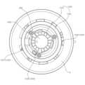
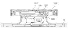
도 9는 본 개시의 실시 예에 따른 가습기의 하부 살균모듈에 관한 설명에 참조되는 도면이고, 도 10은 본 개시의 실시 예에 따른 가습기의 베이스 커버에 관한 설명에 참조되는 도면이다.FIG. 9 is a drawing for reference in a description of a lower sterilizing module of a humidifier according to an embodiment of the present disclosure, and FIG. 10 is a drawing for reference in a description of a base cover of a humidifier according to an embodiment of the present disclosure.
도 9와 도 10을 참조하면, 가습기(1)는, 케이스(10)와 상기 케이스(10) 하측에 배치되는 베이스(13)와 상기 케이스(10) 내부에 배치되는 필터(31)를 포함한다. 상기 필터(31)는 상술한 가습어셈블리(40)의 하측에 배치된다. 상기 필터(31)는 전체적으로 실린더 형상으로 형성될 수 있다.Referring to FIGS. 9 and 10, the humidifier (1) includes a case (10), a base (13) positioned on the lower side of the case (10), and a filter (31) positioned inside the case (10). The filter (31) is positioned on the lower side of the humidifying assembly (40) described above. The filter (31) may be formed in an overall cylindrical shape.
상기 베이스(13)는 가습기(1)의 하면을 형성하며, 실내 공간의 바닥 등에 놓일 수 있다. 상기 베이스(13)는 전체적으로 원판(circular plate) 형상으로 형성될 수 있다.The above base (13) forms the lower surface of the humidifier (1) and can be placed on the floor of an indoor space, etc. The above base (13) can be formed in an overall circular plate shape.
상기 필터(31)는 상기 필터(31)를 상하방향으로 관통하여 형성되는 내부 중공(315)을 포함할 수 있다. 공기는 상기 필터(31)의 외주면으로부터 내주면으로 유동하며 정화될 수 있고, 내부 중공(315)을 거쳐 상기 필터(31)의 상측으로 유동할 수 있다.The above filter (31) may include an internal hollow space (315) formed by vertically penetrating the filter (31). Air may flow from the outer surface of the filter (31) to the inner surface and be purified, and may flow to the upper side of the filter (31) through the internal hollow space (315).
또한, 가습기(1)는, 상기 베이스(13) 상측에 배치되고, 상기 케이스(10)가 분리 가능하게 결합되는 베이스 커버(1000)를 포함한다.In addition, the humidifier (1) includes a base cover (1000) that is placed on the upper side of the base (13) and to which the case (10) is detachably connected.
살균모듈(900)은, 상기 베이스 커버(1000)에 배치되고, 상방의 상기 필터(31) 내부 중공(315)으로 자외선 광을 조사한다. 이에 따라, 필터(31)와 내부 공간(315)을 살균할 수 있다.The sterilization module (900) is placed on the base cover (1000) and irradiates ultraviolet light into the inner hollow space (315) of the filter (31) above. Accordingly, the filter (31) and the inner space (315) can be sterilized.
한편, 상기 필터(31)의 상측에는 팬(32)이 배치되어, 상기 필터(31)의 둘레면으로부터 유입된 공기를 상기 필터(31)의 상측으로 유동시킬 수 있다. 팬모터(33)는 상기 팬(32)의 상측에 배치되어 상기 팬(32)을 회전시킬 수 있다.Meanwhile, a fan (32) is arranged on the upper side of the filter (31) to cause air drawn in from the peripheral surface of the filter (31) to flow to the upper side of the filter (31). A fan motor (33) is arranged on the upper side of the fan (32) to rotate the fan (32).
살균모듈(900)은, 상기 필터(31) 내부 중공(315)으로 자외선 광을 조사하고, 필터(31)와 내부 중공(315) 뿐만 아니라, 내부 중공(315)의 상측에 배치되는 팬(32)도 살균할 수 있다.The sterilization module (900) irradiates ultraviolet light into the internal hollow space (315) of the filter (31), and can sterilize not only the filter (31) and the internal hollow space (315), but also the fan (32) positioned above the internal hollow space (315).
상기 살균모듈(900)은, 상기 베이스 커버(1000)에 상기 케이스(10)가 결합되고 상기 필터(31)가 안착되면, 상기 필터 내부 중공(315)으로 자외선 광을 조사한다. 또한, 상기 살균모듈(900)은, 상기 베이스 커버(1000)에 상기 케이스(10)가 결합되지 않거나 상기 필터(31)가 안착되지 않으면, 상기 필터 내부 중공(315)으로 자외선 광을 조사하지 않는다. 또한, 상기 살균모듈(900)이 자외선 광을 조사하고 있는 중에도, 상기 베이스 커버(1000)에서 상기 케이스(10)가 분리되거나 상기 필터(31)가 제거되면, 자외선 광의 조사를 중지한다. 이에 따라, 자외선 광이 사용자의 눈으로 조사되는 안전 사고를 방지할 수 있다.The sterilizing module (900) irradiates ultraviolet light into the hollow space (315) inside the filter when the case (10) is coupled to the base cover (1000) and the filter (31) is seated. In addition, the sterilizing module (900) does not irradiate ultraviolet light into the hollow space (315) inside the filter when the case (10) is not coupled to the base cover (1000) or the filter (31) is not seated. In addition, even while the sterilizing module (900) is irradiating ultraviolet light, if the case (10) is separated from the base cover (1000) or the filter (31) is removed, the irradiation of ultraviolet light is stopped. Accordingly, a safety accident in which ultraviolet light is irradiated into the user's eyes can be prevented.
상기 베이스 커버(1000)에는, 상기 케이스(10)의 결합 여부, 상기 필터(31)의 안착 여부를 감지하기 위한 센싱 수단이 배치된다. 예를 들어, 상기 베이스 커버(1000)에는, 버튼들(1030)이 배치된다. 상기 케이스(10)의 결합 및 상기 필터(31)의 안착에 따라 상기 버튼들(1030)이 눌러지면, 제어부(34)는 상기 케이스(10)의 결합 여부, 상기 필터(31)의 안착 여부를 판별할 수 있다. 상기 제어부(34)는, 상기 버튼들(1030)의 동작으로 상기 베이스 커버(1000)에 상기 케이스(10)가 결합되고 상기 필터(31)가 안착된 것이 판별되면, 상기 필터 내부 중공(315)으로 자외선 광을 조사하도록 상기 살균모듈(900)을 제어한다.In the base cover (1000), a sensing means is arranged to detect whether the case (10) is coupled and whether the filter (31) is seated. For example, buttons (1030) are arranged in the base cover (1000). When the buttons (1030) are pressed according to the coupling of the case (10) and the seating of the filter (31), the control unit (34) can determine whether the case (10) is coupled and whether the filter (31) is seated. When the control unit (34) determines that the case (10) is coupled to the base cover (1000) and the filter (31) is seated by the operation of the buttons (1030), it controls the sterilizing module (900) to irradiate ultraviolet light into the inner hollow space (315) of the filter.
한편, 상기 케이스(10)는, 상기 베이스 커버(1000)에 분리 가능하게 결합되는 제1 케이스(1101)(도 11 참조), 및, 상기 베이스 커버(1000)에 대하여 상기 제1 케이스(1101)와 대향하고, 상기 베이스 커버(1000)에 분리 가능하게 결합되는 제2 케이스(1102)(도 12 참조)를 포함할 수 있다.Meanwhile, the case (10) may include a first case (1101) (see FIG. 11) detachably coupled to the base cover (1000), and a second case (1102) (see FIG. 12) facing the first case (1101) and detachably coupled to the base cover (1000) with respect to the base cover (1000).
상기 제1 케이스(1101)와 상기 제2 케이스(1102)는 각각 상기 베이스 커버(1000)에 결합될 수 있다.The first case (1101) and the second case (1102) can each be coupled to the base cover (1000).
상기 살균 모듈(900)은, 상기 제1 케이스(1101)와 상기 제2 케이스(1102) 중에 적어도 하나가 상기 베이스 커버(100)에서 분리되면, 상기 자외선 광의 조사를 중지시킬 수 있다.The above sterilization module (900) can stop irradiating the ultraviolet light when at least one of the first case (1101) and the second case (1102) is separated from the base cover (100).
한편, 상기 베이스 커버(1000)는, 상기 제1 케이스(1101)가 상기 베이스 커버(1000)에 결합되면 동작하는 제1 버튼(1031)과, 상기 제2 케이스(1102)가 상기 베이스 커버(1000)에 결합되면 동작하는 제2 버튼(1032)을 포함할 수 있다. 예를 들어, 제1,2 버튼(1031, 1032)는, 각각 상기 제1,2 케이스(1101, 1102)에 결합되면, 온(on)될 수 있고, 그렇지 않으면 오프(off)될 수 있다.Meanwhile, the base cover (1000) may include a first button (1031) that operates when the first case (1101) is coupled to the base cover (1000), and a second button (1032) that operates when the second case (1102) is coupled to the base cover (1000). For example, the first and second buttons (1031, 1032) may be turned on when coupled to the first and second cases (1101, 1102), respectively, and may be turned off otherwise.
상기 제1 케이스(1101)는, 상기 제1 케이스(1101)의 내면에서 돌출되고, 상기 제1 버튼(1031)과 접촉하는 제1 리브(1110)를 포함할 수 있다. 또한, 상기 제2 케이스(1102)는, 상기 제2 케이스(1102)의 내면에서 돌출되고, 상기 제2 버튼(1032)과 접촉하는 제2 리브(1120)를 포함할 수 있다.The first case (1101) may include a first rib (1110) that protrudes from the inner surface of the first case (1101) and comes into contact with the first button (1031). In addition, the second case (1102) may include a second rib (1120) that protrudes from the inner surface of the second case (1102) and comes into contact with the second button (1032).
도 11과 도 12는 본 개시의 실시 예에 따른 가습기의 케이스와 베이스 커버의 결합에 관한 설명에 참조되는 도면이다.FIGS. 11 and 12 are drawings for reference in explaining the combination of a case and a base cover of a humidifier according to an embodiment of the present disclosure.
도 11을 참조하면, 상기 제1 케이스(1101)가 상기 베이스 커버(1000)에 결합되면, 상기 제1 케이스(1101)에서 돌출된 제1 리브(1110)가 제1 버튼(1031)을 누른다. 제1 버튼(1031)이 눌러지면, 이에 대응하는 신호가 제1 버튼(1031)에서 제어부(34)로 전달될 수 있다. 이에 따라, 상기 제어부(34)는, 상기 제1 케이스(1101)와 상기 베이스 커버(1000)의 결합 여부를 판별하고, 상기 실균 모듈(900)의 동작을 제어할 수 있다.Referring to Fig. 11, when the first case (1101) is coupled to the base cover (1000), the first rib (1110) protruding from the first case (1101) presses the first button (1031). When the first button (1031) is pressed, a corresponding signal can be transmitted from the first button (1031) to the control unit (34). Accordingly, the control unit (34) can determine whether the first case (1101) and the base cover (1000) are coupled, and control the operation of the sterilization module (900).
도 12를 참조하면, 상기 제2 케이스(1102)가 상기 베이스 커버(1000)에 결합되면, 상기 제2 케이스(1102)에서 돌출된 제2 리브(1120)가 상기 제2 버튼(1032)을 누른다. 상기 제2 버튼(1032)이 눌러지면, 이에 대응하는 신호가 상기 제2 버튼(1032)에서 제어부(34)로 전달될 수 있다. 이에 따라, 상기 제어부(34)는, 상기 제2 케이스(1102)와 상기 베이스 커버(1000)의 결합 여부를 판별하고, 상기 실균 모듈(900)의 동작을 제어할 수 있다.Referring to Fig. 12, when the second case (1102) is coupled to the base cover (1000), the second rib (1120) protruding from the second case (1102) presses the second button (1032). When the second button (1032) is pressed, a corresponding signal can be transmitted from the second button (1032) to the control unit (34). Accordingly, the control unit (34) can determine whether the second case (1102) and the base cover (1000) are coupled, and control the operation of the sterilization module (900).
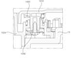
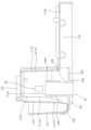
한편, 상기 베이스 커버(1000)는, 상기 필터(31)의 하부면과 접촉하는 필터 커버(1010)와 상기 필터 커버(1010)의 하측에 결합되는 커버 바디(1020)를 포함할 수 있다. 상기 필터 커버(1010)는 베이스 커버(1000)의 상면 중 일부를 형성할 수 있다. 상기 필터 커버(1010)는 베이스 커버(1000)의 중앙부 상면을 형성하고, 상기 필터 커버(1010) 측면과 하부에 커버 바디(1020)가 위치할 수 있다.Meanwhile, the base cover (1000) may include a filter cover (1010) that comes into contact with the lower surface of the filter (31) and a cover body (1020) that is coupled to the lower side of the filter cover (1010). The filter cover (1010) may form a part of the upper surface of the base cover (1000). The filter cover (1010) forms the upper surface of the central portion of the base cover (1000), and the cover body (1020) may be positioned on the side and lower side of the filter cover (1010).
상기 살균 모듈(900)은, 상기 필터 커버(1010)와 상기 커버 바디(1020) 사이 공간에 배치될 수 있다. 또한, 상기 살균 모듈(900)은, 상기 필터 커버(1010)에 결합될 수 있다.The above sterilizing module (900) can be placed in the space between the filter cover (1010) and the cover body (1020). In addition, the sterilizing module (900) can be coupled to the filter cover (1010).
상기 살균 모듈(900)은, 보드(920) 및 상기 보드(920)에 실장되는 광원(910)을 포함할 수 있다. 보드(920)는 필터 커버(1010)의 하면에 장착될 수 있다. 보드(920)는 기판이라 칭할 수 있다. 예를 들면, 보드(920)는 PCB(Printed Circuit Board)일 수 있다. 광원(910)은 자외선 파장대의 빛을 제공할 수 있다. 예를 들면, 광원(910)은 100 ~ 280 nm의 파장의 빛을 제공하는 UVC LED이거나 UVC 램프일 수 있다. 이에 따라, 광원(910)의 빛은 팬(32)에 존재하는 세균 또는 미생물을 살균할 수 있다. 또한, 광원(910)의 빛은 필터(31)에 존재하거나 필터(31)를 통과한 공기 중에 존재하는 세균 또는 미생물을 살균할 수 있다.The above sterilization module (900) may include a board (920) and a light source (910) mounted on the board (920). The board (920) may be mounted on the lower surface of the filter cover (1010). The board (920) may be referred to as a substrate. For example, the board (920) may be a PCB (Printed Circuit Board). The light source (910) may provide light in an ultraviolet wavelength range. For example, the light source (910) may be a UVC LED or a UVC lamp that provides light with a wavelength of 100 to 280 nm. Accordingly, the light of the light source (910) may sterilize bacteria or microorganisms existing in the fan (32). In addition, the light of the light source (910) may sterilize bacteria or microorganisms existing in the filter (31) or existing in the air that has passed through the filter (31).
한편, 상기 필터 커버(1010)와 상기 커버 바디(1020)는, 복수의 결합부(1040)에서 스크류 등 체결부재(1045)로 결합될 수 있다. 예를 들면, 복수의 결합부(1040) 각각의 내주면에 나사산이 형성될 수 있고, 복수개의 체결부재들(1045) 각각은 상기 내주면에 체결되는 스크류일 수 있다.Meanwhile, the filter cover (1010) and the cover body (1020) may be joined by a plurality of joining parts (1040) with a fastening member (1045) such as a screw. For example, a screw thread may be formed on the inner surface of each of the plurality of joining parts (1040), and each of the plurality of fastening members (1045) may be a screw fastened to the inner surface.
도 11을 참조하면, 상기 필터 커버(1010)는, 상면에서 하측으로 함몰되는 함몰부(1015)를 포함하고, 상기 함몰부(1015)의 중앙에는 상기 자외선 광이 관통하는 홀(1016)이 형성될 수 있다.Referring to FIG. 11, the filter cover (1010) includes a recessed portion (1015) that recesses downward from the upper surface, and a hole (1016) through which the ultraviolet light passes may be formed in the center of the recessed portion (1015).
도 13, 도 14a, 도 14b는 본 개시의 실시 예에 따른 가습기의 필터 안착에 관한 설명에 참조되는 도면이다. 도 13은 필터 안착에 따른 제3 리브(1050)와 제3 버튼(1033)의 접촉을 예시하고, 도 14a는 필터가 없는 상태, 도 14b는 필터가 안착된 상태를 예시한다.FIG. 13, FIG. 14a, and FIG. 14b are drawings for reference in the description of filter installation of a humidifier according to an embodiment of the present disclosure. FIG. 13 illustrates contact between a third rib (1050) and a third button (1033) according to filter installation, and FIG. 14a illustrates a state without a filter, and FIG. 14b illustrates a state with a filter installed.
도 13, 도 14a, 도 14b를 참조하면, 상기 베이스 커버(1000)는, 상기 필터 커버(1010)와 상기 커버 바디(1020)에 연결되는 탄성부재(1400)를 더 포함한다. 또한, 상기 필터 커버(1010)는, 하측으로 돌출되는 제3 리브(1050)를 포함한다. 상기 커버 바디(1020)는, 상기 필터 커버(1010)에 상기 필터(31)가 안착되면, 상기 탄성부재(1400)의 압축에 따라 상기 제3 리브(1050)와 접촉하는 제3 버튼(1033)을 포함한다. 예를 들어, 제3 버튼(1033)은, 상기 필터 커버(1010)에 상기 필터(31)가 안착되면, 온(on)되고, 그렇지 않으면, 오프(off)될 수 있다.Referring to FIG. 13, FIG. 14a, and FIG. 14b, the base cover (1000) further includes an elastic member (1400) connected to the filter cover (1010) and the cover body (1020). In addition, the filter cover (1010) includes a third rib (1050) that protrudes downward. The cover body (1020) includes a third button (1033) that comes into contact with the third rib (1050) according to the compression of the elastic member (1400) when the filter (31) is seated on the filter cover (1010). For example, the third button (1033) may be turned on when the filter (31) is seated on the filter cover (1010), and may be turned off otherwise.
탄성부재(1400)는 탄성을 지닐 수 있다. 탄성부재(1400)는 필터 커버(1010)와 커버 바디(1020) 사이에 위치할 수 있고, 필터 커버(1010)와 커버 바디(1020)에 고정될 수 있다. 예를 들면, 탄성부재(1400)는 스프링일 수 있고, 복수개의 결합부들(1040) 각각의 외주면에 감길 수 있다. 상기 탄성부재(1400)는, 결합부(1040)의 체결부재(1045) 외부에 배치될 수 있다. 탄성부재(1400)는, 상기 필터 커버(1010)와 상기 커버 바디(1020)에 접촉하고 있거나, 적어도 상기 커버 바디(1020)에는 접촉하고 있다가, 상기 필터(31)의 안착으로 압축될 수 있다.The elastic member (1400) may have elasticity. The elastic member (1400) may be positioned between the filter cover (1010) and the cover body (1020), and may be fixed to the filter cover (1010) and the cover body (1020). For example, the elastic member (1400) may be a spring, and may be wound around the outer surface of each of the plurality of connecting portions (1040). The elastic member (1400) may be arranged outside the fastening member (1045) of the connecting portion (1040). The elastic member (1400) may be in contact with the filter cover (1010) and the cover body (1020), or may be in contact with at least the cover body (1020), and may be compressed by the settling of the filter (31).
필터 커버(1010)에 하중이 가해지지 않으면, 탄성부재(1400)는 탄성 복원될 수 있고, 필터 커버(1010)는 커버 바디(1020)로부터 멀어질 수 있다.When no load is applied to the filter cover (1010), the elastic member (1400) can be elastically restored, and the filter cover (1010) can move away from the cover body (1020).
도 14a를 참조하면, 필터(31)가 없으면, 탄성부재(1400)에 의해 필터 커버(1010)가 올라가 있다. 도 14b를 참조하면, 필터(31) 안착시 탄성부재(1400)가 압축되며 필터 커버(1010)가 내려간다.Referring to Fig. 14a, when there is no filter (31), the filter cover (1010) is raised by the elastic member (1400). Referring to Fig. 14b, when the filter (31) is placed, the elastic member (1400) is compressed and the filter cover (1010) is lowered.
상기 필터 커버(1010) 위에 상기 필터(31)가 안착되면, 상기 탄성부재(1400)가 압축되면서 상기 필터 커버(1010)가 내려간다. 상기 필터 커버(1010)가 내려가면서, 상기 필터 커버(1010) 하측으로 돌출되는 제3 리브(1050)가 상기 제3 버튼(1033)을 누른다. 상기 제3 버튼(1033)이 눌러지면, 이에 대응하는 신호가 상기 제3 버튼(1033)에서 제어부(34)로 전달될 수 있다. 이에 따라, 상기 제어부(34)는, 상기 필터(31)의 안착 여부를 판별하고, 상기 실균 모듈(900)의 동작을 제어할 수 있다.When the filter (31) is placed on the filter cover (1010), the elastic member (1400) is compressed and the filter cover (1010) goes down. As the filter cover (1010) goes down, the third rib (1050) protruding downward from the filter cover (1010) presses the third button (1033). When the third button (1033) is pressed, a corresponding signal can be transmitted from the third button (1033) to the control unit (34). Accordingly, the control unit (34) can determine whether the filter (31) is placed and control the operation of the sterilization module (900).
또한, 상기 살균 모듈(900)은, 상기 제3 버튼(1033)이 상기 제3 리브(1050)와 분리되면, 상기 자외선 광의 조사를 중지시킬 수 있다.Additionally, the sterilizing module (900) can stop irradiating the ultraviolet light when the third button (1033) is separated from the third rib (1050).
본 개시의 실시 예에 따른 가습기(1)는 하부에 살균 모듈(900)이 위치하며, 살균 모듈(900)은 제1 내지 제3 버튼(1031, 1032, 1033)이 모두 눌러져 있어야 작동한다. 따라서, 사용자가 필터(31)를 빼거나 제품 내부를 관리할 때, 자외선 광이 눈에 조사될 위험을 방지할 수 있다.The humidifier (1) according to the embodiment of the present disclosure has a sterilizing module (900) positioned at the bottom, and the sterilizing module (900) operates only when the first to third buttons (1031, 1032, 1033) are all pressed. Accordingly, when a user removes the filter (31) or manages the inside of the product, the risk of ultraviolet light being irradiated to the eyes can be prevented.
또한, 제1 내지 제3 버튼(1031, 1032, 1033)이 모두 온(on) 상태이면, 상기 제어부(34)는 광원(910)을 동작시킬 수 있다. 즉, 필터(31)가 베이스 커버(1000)에 안착되고 제1 케이스(1101)와 제2 케이스(1102)가 베이스 커버(1000)에 결합되면, 상기 제어부(34)는 광원(910)을 동작시킬 수 있다.In addition, when the first to third buttons (1031, 1032, 1033) are all turned on, the control unit (34) can operate the light source (910). That is, when the filter (31) is mounted on the base cover (1000) and the first case (1101) and the second case (1102) are combined with the base cover (1000), the control unit (34) can operate the light source (910).
이에 따라, 상기 제어부(34)는 필터(31)와 케이스(10)에 의해 광원(910)의 빛이 외부로 유출되는 것이 차단될 수 있을 때 광원(910)을 동작시켜 팬(32)을 살균할 수 있다. 다시 말해, 상기 제어부는 필터(31)나 케이스(10)가 가습기(1)에서 분리되었을 때 광원(910)의 동작을 중지시켜 빛의 외부 유출을 원천적으로 차단할 수 있다.Accordingly, the control unit (34) can sterilize the fan (32) by operating the light source (910) when the light of the light source (910) can be blocked from leaking outward by the filter (31) and the case (10). In other words, the control unit can stop the operation of the light source (910) when the filter (31) or the case (10) is separated from the humidifier (1) to fundamentally block the external leak of light.
도 8을 참조하여 상술한 바와 같이, 상기 가습어셈블리(40)는, 물이 수용되는 공간이 형성된 가습챔버(421)와 상기 가습챔버(421) 내부로 빛(예, 자외선 광)을 조사하는 살균장치(60)를 포함하여, 가습챔버(421) 내 잔수를 살균할 수 있다.As described above with reference to FIG. 8, the humidifying assembly (40) includes a humidifying chamber (421) in which a space for containing water is formed, and a sterilizing device (60) that irradiates light (e.g., ultraviolet light) into the interior of the humidifying chamber (421), thereby sterilizing residual water within the humidifying chamber (421).
또한, 상기 가습어셈블리(40)는, 상기 가습챔버(421)의 둘레벽을 따라 배치되는 반사판(4211s, 4212s, 4213s, 4214s)(도 15, 도 16 참조)을 포함하여, 음영 지역이 없도록 자외선 광을 가습챔버(421) 내부로 반사할 수 있다. 반사판(4211s, 4212s, 4213s, 4214s)은 상기 살균장치(60)와 이격되고, 상기 살균장치(60)와 마주하게 배치될 수 있다.In addition, the humidifying assembly (40) can reflect ultraviolet light into the humidifying chamber (421) without leaving a shaded area by including reflectors (4211s, 4212s, 4213s, 4214s) (see FIGS. 15 and 16) arranged along the perimeter wall of the humidifying chamber (421). The reflectors (4211s, 4212s, 4213s, 4214s) can be arranged spaced apart from the sterilizing device (60) and facing the sterilizing device (60).
도 15는 본 개시의 실시 예에 따른 가습기 일부의 단면도로, 가습어셈블리(40)의 일부를 도 8에 도시된 7-7선도를 따라 수직방향으로 절개한 단면도이다.FIG. 15 is a cross-sectional view of a portion of a humidifier according to an embodiment of the present disclosure, which is a cross-sectional view taken vertically along line 7-7 of FIG. 8 of a portion of a humidifying assembly (40).
도 15를 참조하면, 살균장치(60)는 제1 측벽(4213)에 배치될 수 있다. 살균장치(60)는 외측벽(4211)과 내측벽(4212)의 사이에 위치할 수 있다.Referring to FIG. 15, the sterilizing device (60) may be placed on the first side wall (4213). The sterilizing device (60) may be located between the outer side wall (4211) and the inner side wall (4212).
가습챔버(421)는 챔버하벽(4215)을 포함할 수 있다. 챔버하벽(4215)은 진동장치(422)와 결합될 수 있다. 진동장치(422)는 챔버하벽(4215)의 하측에 배치될 수 있다.The humidifying chamber (421) may include a chamber lower wall (4215). The chamber lower wall (4215) may be coupled with a vibration device (422). The vibration device (422) may be placed on the lower side of the chamber lower wall (4215).
살균장치(60)는 아웃렛(46)과 챔버하벽(4215) 사이에 위치할 수 있다. 살균장치(60)는 아웃렛(46)보다 하측에 위치할 수 있다.The sterilizer (60) may be located between the outlet (46) and the chamber lower wall (4215). The sterilizer (60) may be located lower than the outlet (46).
아웃렛(46)은 분무유입구(463)를 포함할 수 있다. 분무유입구(463)는 가습챔버(421)의 내측으로 연장될 수 있다.The outlet (46) may include a spray inlet (463). The spray inlet (463) may extend into the interior of the humidifying chamber (421).
아웃렛(46)은 연통구(467)를 포함할 수 있다. 연통구(467)는 커넥터결합부(464)와 마주할 수 있다. 연통구(467)는 분무유입구(463)에 개구될 수 있다.The outlet (46) may include a communication port (467). The communication port (467) may face the connector joint (464). The communication port (467) may be opened to the spray inlet port (463).
아웃렛(46)은 아웃렛하단(468)을 포함할 수 있다. 아웃렛하단(468)은 가습챔버(421)의 내부에 위치할 수 있다.The outlet (46) may include an outlet bottom (468). The outlet bottom (468) may be located inside the humidifying chamber (421).
살균장치(60)는 아웃렛하단(468)보다 하측에 위치할 수 있다. 살균장치(60)는 챔버하벽(4215)보다 상측에 위치할 수 있다.The sterilizing device (60) may be located lower than the outlet bottom (468). The sterilizing device (60) may be located higher than the chamber lower wall (4215).
가습어셈블리(40)는 반사판(4211s, 4212s, 4213s, 4214s)을 포함할 수 있다. 반사판(4211s, 4212s, 4213s, 4214s)은 가습챔버(421)의 내부공간을 향할 수 있다. 반사판(4211s, 4212s, 4213s, 4214s)은 가습챔버(421)의 측벽(4211, 4212, 4213, 4214)에 배치될 수 있다. 살균장치(60)에서 조사된 빛은, 반사판(4211s, 4212s, 4213s, 4214s)에 도달하여 반사될 수 있다.The humidifying assembly (40) may include reflectors (4211s, 4212s, 4213s, 4214s). The reflectors (4211s, 4212s, 4213s, 4214s) may face the interior space of the humidifying chamber (421). The reflectors (4211s, 4212s, 4213s, 4214s) may be placed on the side walls (4211, 4212, 4213, 4214) of the humidifying chamber (421). Light irradiated from the sterilizing device (60) may reach the reflectors (4211s, 4212s, 4213s, 4214s) and be reflected.
반사판(4211s, 4212s, 4213s, 4214s)은, 외측반사판(4211s)을 포함할 수 있다. 외측반사판(4211s)은 외측벽(4211)에 배치될 수 있다. 외측반사판(4211s)은 외측벽(4211)의 가습챔버(421)의 내부공간을 향하는 면에 결합될 수 있다.The reflectors (4211s, 4212s, 4213s, 4214s) may include an outer reflector (4211s). The outer reflector (4211s) may be arranged on the outer wall (4211). The outer reflector (4211s) may be coupled to a surface of the outer wall (4211) facing the interior space of the humidifying chamber (421).
반사판(4211s, 4212s, 4213s, 4214s)은, 내측반사판(4212s)을 포함할 수 있다. 내측반사판(4212s)은 내측벽(4212)에 배치될 수 있다. 내측반사판(4212s)은 내측벽(4212)의 가습챔버(421)의 내부공간을 향하는 면에 결합될 수 있다.The reflectors (4211s, 4212s, 4213s, 4214s) may include an inner reflector (4212s). The inner reflector (4212s) may be arranged on the inner wall (4212). The inner reflector (4212s) may be coupled to a surface of the inner wall (4212) facing the inner space of the humidifying chamber (421).
반사판(4211s, 4212s, 4213s, 4214s)은, 제1 측면반사판(4213s)을 포함할 수 있다. 제1 측면반사판(4213s)은 제1 측벽(4213)에 배치될 수 있다. 제1 측면반사판(4213s)은 제1 측벽(4213)의 가습챔버(421)의 내부공간을 향하는 면에 결합될 수 있다.The reflectors (4211s, 4212s, 4213s, 4214s) may include a first side reflector (4213s). The first side reflector (4213s) may be arranged on the first side wall (4213). The first side reflector (4213s) may be coupled to a surface of the first side wall (4213) facing the interior space of the humidifying chamber (421).
반사판(4211s, 4212s, 4213s, 4214s)은, 제2 측면반사판(4214s)(도 10참조)을 포함할 수 있다. 제2 측면반사판(4214s)은 제2 측벽(4214)에 배치될 수 있다. 제2 측면반사판(4214s)은 제2 측벽(4214)의 가습챔버(421)의 내부공간을 향하는 면에 결합될 수 있다.The reflectors (4211s, 4212s, 4213s, 4214s) may include a second side reflector (4214s) (see FIG. 10). The second side reflector (4214s) may be disposed on the second side wall (4214). The second side reflector (4214s) may be coupled to a surface of the second side wall (4214) facing the interior space of the humidifying chamber (421).
도 16은, 본 개시의 실시 예에 따른 가습기 일부의 단면도로, 가습어셈블리(40)의 일부를 도 8에 도시된 8-8선도를 따라 수직방향으로 절개하여 도시한 단면도이다.FIG. 16 is a cross-sectional view of a portion of a humidifier according to an embodiment of the present disclosure, taken vertically along line 8-8 of FIG. 8, showing a portion of the humidifying assembly (40).
도 16을 참조하면, 살균장치(60)는 제1 측벽(4213)에 배치될 수 있다. 살균장치(60)는 가습챔버(421)의 내부공간을 향해 빛을 조사할 수 있다.Referring to Fig. 16, a sterilizing device (60) may be placed on the first side wall (4213). The sterilizing device (60) may irradiate light toward the internal space of the humidifying chamber (421).
아웃렛(46)은 리세스(4681)를 포함할 수 있다. 리세스(4681)는 아웃렛(46)의 하단에 형성될 수 있다. 리세스(4681)는 아웃렛(46)으로부터 상방으로 함몰될 수 있다.The outlet (46) may include a recess (4681). The recess (4681) may be formed at the bottom of the outlet (46). The recess (4681) may be sunken upward from the outlet (46).
살균장치(60)는 아웃렛하단(468)보다 하측에 위치할 수 있다. 살균장치(60)는 리세스(4681)보다 하측에 위치할 수 있다.The sterilizing device (60) may be located lower than the outlet bottom (468). The sterilizing device (60) may be located lower than the recess (4681).
살균장치(60)는 램프(61)를 포함할 수 있다. 살균장치(60)는 발광부(62)를 포함할 수 있다. 램프(61)는 가습챔버(421)의 내측공간에 노출될 수 있다. 램프(61)는 발광부(62)로부터 발생된 자외선을 가습챔버(421) 내부로 조사할 수 있다. 발광부(62)는 가습챔버(421)의 외측에 배치될 수 있다. 발광부(62)는 램프(61)를 향해 자외선을 발생시킬 수 있다.The sterilizing device (60) may include a lamp (61). The sterilizing device (60) may include a light-emitting portion (62). The lamp (61) may be exposed to the inner space of the humidifying chamber (421). The lamp (61) may irradiate ultraviolet rays generated from the light-emitting portion (62) into the interior of the humidifying chamber (421). The light-emitting portion (62) may be arranged on the outside of the humidifying chamber (421). The light-emitting portion (62) may generate ultraviolet rays toward the lamp (61).
서포터(466)는 가습챔버(421)의 내부로 연장될 수 있다. 서포터(466)는 제2 측벽(4214)을 따라 연장될 수 있다. 서포터(466)는 제1 측벽(4213)과 이격될 수 있다. 서포터(466)는 살균장치(60)와 마주할 수 있다. 서포터(466)는 제2 측벽(4214)의 일부를 커버할 수 있다. 서포터(466)는 불투명한 재질일 수 있다. 다만, 서포터(466)는 투명한 재질일 수 있고, 자외선 빛을 반사시킬 수도 있다.The supporter (466) may extend into the interior of the humidifying chamber (421). The supporter (466) may extend along the second side wall (4214). The supporter (466) may be spaced apart from the first side wall (4213). The supporter (466) may face the sterilizing device (60). The supporter (466) may cover a portion of the second side wall (4214). The supporter (466) may be made of an opaque material. However, the supporter (466) may be made of a transparent material and may reflect ultraviolet light.
제2 측면반사판(4214s)은 서포터(466)의 하측에 노출될 수 있다. 다만, 제2 측면반사판(4214s)은 서포터(466)의 일면에 결합될 수도 있다. 이 경우, 살균장치(60)에서 조사된 빛은, 서포터(466)의 일면에 배치된 제2 측면반사판(4214s)에 반사될 수 있다.The second side reflector (4214s) may be exposed on the lower side of the supporter (466). However, the second side reflector (4214s) may also be coupled to one side of the supporter (466). In this case, light irradiated from the sterilizing device (60) may be reflected on the second side reflector (4214s) disposed on one side of the supporter (466).
서포터(466)는 제2 모서리부(4212c)와 마주할 수 있다. 서포터(466)의 일부는 제2 모서리부(4212c)가 굴곡진 방향으로 연장될 수 있다.The supporter (466) may face the second edge portion (4212c). A portion of the supporter (466) may extend in the direction in which the second edge portion (4212c) is curved.
제1 모서리부(4212b)는 분무유입구(463)와 제1 측벽(4213) 사이에 위치할 수 있다.The first edge portion (4212b) may be located between the spray inlet (463) and the first side wall (4213).
반사판(4211s, 4212s, 4213s, 4214s)은, 딤플(4216)을 포함할 수 있다. 딤플(4216)은 복수개가 형성될 수 있다. 딤플(4216)은 반사판(4211s, 4212s, 4213s, 4214s)으로부터 가습챔버(421)의 내부공간과 멀어지는 방향으로 함몰될 수 있다.The reflector (4211s, 4212s, 4213s, 4214s) may include a dimple (4216). A plurality of dimples (4216) may be formed. The dimples (4216) may be sunken in a direction away from the reflector (4211s, 4212s, 4213s, 4214s) and the internal space of the humidifying chamber (421).
살균장치(60)에서 조사된 자외선 빛은, 반사판(4211s, 4212s, 4213s, 4214s)에서 반사되어 가습챔버(421) 내부로 균일하게 확산될 수 있다. 이 때, 딤플(4216)은 자외선 빛의 반사각을 다양화시킴으로써, 빛의 확산을 촉진시킬 수 있다.The ultraviolet light irradiated from the sterilizing device (60) can be reflected from the reflectors (4211s, 4212s, 4213s, 4214s) and evenly diffused into the humidifying chamber (421). At this time, the dimple (4216) can promote the diffusion of light by diversifying the reflection angle of the ultraviolet light.
또한, 제1 내지 제3 버튼(1031, 1032, 1033)이 모두 온(on) 상태이면, 상기 제어부(34)는 가습챔버(421)에 배치된 살균장치(60)를 동작시킬 수 있다. 즉, 필터(31)가 베이스 커버(1000)에 안착되고 제1 케이스(1101)와 제2 케이스(1102)가 베이스 커버(1000)에 결합되면, 상기 제어부(34)는 살균장치(60)를 동작시킬 수 있다. 이에 따라, 필터(31)와 케이스(10)가 분리된 상태에서, 살균장치(60)가 동작하는 것을 방지할 수 있다.In addition, when the first to third buttons (1031, 1032, 1033) are all turned on, the control unit (34) can operate the sterilizing device (60) placed in the humidifying chamber (421). That is, when the filter (31) is mounted on the base cover (1000) and the first case (1101) and the second case (1102) are combined with the base cover (1000), the control unit (34) can operate the sterilizing device (60). Accordingly, the sterilizing device (60) can be prevented from operating while the filter (31) and the case (10) are separated.
도 4에서는, 플로팅밸브를 이용한 물 공급 및 가습어셈블리(40) 구조를 예시하였지만, 본 개시는 이에 한정되지 않는다. 예를 들어, 본 개시의 실시 예들은, 솔레노이드 밸브를 이용하여 물을 공급하고, 다른 구조의 가습어셈블리(40)에도 적용 가능하다.In Fig. 4, a water supply and humidification assembly (40) structure using a floating valve is exemplified, but the present disclosure is not limited thereto. For example, the embodiments of the present disclosure can be applied to a humidification assembly (40) that supplies water using a solenoid valve and has a different structure.
도 17은 본 개시의 일 실시 예에 따른 가습어셈블리의 종단면도이다.FIG. 17 is a cross-sectional view of a humidifier assembly according to one embodiment of the present disclosure.
도 17을 참조하면, 가습어셈블리(40)는 메인 하우징(1701), 공급관(1710), 제1 밸브(1712), 가열챔버(411), 제1 연결관(1740), 드레인 관(1790), 가습챔버(421), 및 구획 커버(1770)를 포함할 수 있다.Referring to FIG. 17, the humidifying assembly (40) may include a main housing (1701), a supply pipe (1710), a first valve (1712), a heating chamber (411), a first connecting pipe (1740), a drain pipe (1790), a humidifying chamber (421), and a compartment cover (1770).
메인 하우징(1701)은 케이스(10) 내부에 배치될 수 있다. 메인 하우징(1701)은 후술하는 가열챔버(411), 및 가습챔버(421)를 수용할 수 있다. 메인 하우징(1701)은 상측이 개구될 수 있다.The main housing (1701) can be placed inside the case (10). The main housing (1701) can accommodate a heating chamber (411) and a humidifying chamber (421) described later. The main housing (1701) can have an open upper side.
공급관(1710)은 가습어셈블리(40)로 물이 공급되는 관일 수 있다. 공급관(1710)은 가습어셈블리(40)에 연결될 수 있다. 물통(20)에 저장된 물은 공급관(1710)을 통해 가습어셈블리(40)에 공급될 수 있다. 예를 들어, 물통(20)에 저장된 물은 공급관(1710)을 통해 가열챔버(411)로 이동될 수 있다. 공급관(1710)의 내부에는 공급 챔버(1711)가 형성될 수 있다. 공급관(1710)으로 유입된 물은 공급 챔버(1711)를 통과하여 가열 챔버로 유동할 수 있다. 공급관(1710)으로 유입된 물은 공급 챔버(1711)에 일시적으로 저장될 수 있다.The supply pipe (1710) may be a pipe through which water is supplied to the humidifying assembly (40). The supply pipe (1710) may be connected to the humidifying assembly (40). Water stored in the water tank (20) may be supplied to the humidifying assembly (40) through the supply pipe (1710). For example, water stored in the water tank (20) may be moved to the heating chamber (411) through the supply pipe (1710). A supply chamber (1711) may be formed inside the supply pipe (1710). Water introduced into the supply pipe (1710) may pass through the supply chamber (1711) and flow into the heating chamber. Water introduced into the supply pipe (1710) may be temporarily stored in the supply chamber (1711).
제1 밸브(1712)는 공급관(1710)을 통해 가습어셈블리(40)로 공급되는 물의 유동을 제어할 수 있다. 예를 들어, 제1 밸브(1712)가 열리면 공급 챔버(1711)에 저장된 물이 가열챔버(411)로 이동할 수 있다. 반대로, 제1 밸브(1712)가 닫히면 공급된 물은 공급 챔버(1711)에 일시적으로 저장될 수 있다. 제1 밸브(1712)는 제어부(34)의 전기적 신호에 따라 개폐될 수 있다. 제1 밸브(1712)는 제어부(34))로부터 전원을 공급받을 수 있다. 예를 들어, 제1 밸브(1712)는 솔레노이드 밸브일 수 있다. 제1 밸브(1712)는 가열챔버(411)의 상측에 배치될 수 있다. 제1 밸브(1712)는 공급관(1710)에 배치될 수 있다. 예를 들어, 제1 밸브(1712)는 가열챔버(411)와 공급관(1710) 사이에 배치될 수 있다. 제1 밸브(1712)는 가열챔버(411)로부터 상측으로 이격될 수 있다. 예를 들어, 제1 밸브(1712)는 가열챔버(411)의 상면으로부터 상측으로 이격되어 배치될 수 있다.The first valve (1712) can control the flow of water supplied to the humidifying assembly (40) through the supply pipe (1710). For example, when the first valve (1712) is opened, water stored in the supply chamber (1711) can move to the heating chamber (411). Conversely, when the first valve (1712) is closed, the supplied water can be temporarily stored in the supply chamber (1711). The first valve (1712) can be opened and closed according to an electrical signal of the control unit (34). The first valve (1712) can receive power from the control unit (34). For example, the first valve (1712) can be a solenoid valve. The first valve (1712) can be arranged on the upper side of the heating chamber (411). The first valve (1712) can be arranged in the supply pipe (1710). For example, the first valve (1712) may be positioned between the heating chamber (411) and the supply pipe (1710). The first valve (1712) may be spaced upwardly from the heating chamber (411). For example, the first valve (1712) may be positioned upwardly spaced from the upper surface of the heating chamber (411).
가열챔버(411)는 메인 하우징(1701)의 내부에 배치될 수 있다. 가열챔버(411)는 공급관(1710)을 통해 유입된 물을 가열할 수 있다. 가열챔버(411)는 물을 가열하여 살균할 수 있다. 가열챔버(411)에서 가열된 물은 가습챔버(421)로 유동할 수 있다.The heating chamber (411) can be placed inside the main housing (1701). The heating chamber (411) can heat water introduced through the supply pipe (1710). The heating chamber (411) can heat and sterilize water. The water heated in the heating chamber (411) can flow to the humidifying chamber (421).
제1 연결관(1740)은 가열챔버(411)에 저장된 물이 가습챔버(421)로 유동하는 관일 수 있다. 제1 연결관(1740)은 하류로 갈수록 관의 높이가 낮아질 수 있다. 제1 연결관(1740)은 하류 측을 향하여 하방으로 경사질 수 있다. 제1 연결관(1740)은 열 전도성이 높을 수 있다. 가열챔버(411)에서 가열된 물은 제1 연결관(1740)을 유동하는 과정에서 온도가 낮아질 수 있다.The first connecting pipe (1740) may be a pipe through which water stored in the heating chamber (411) flows to the humidifying chamber (421). The height of the first connecting pipe (1740) may decrease as it goes downstream. The first connecting pipe (1740) may be inclined downward toward the downstream side. The first connecting pipe (1740) may have high thermal conductivity. The temperature of water heated in the heating chamber (411) may decrease as it flows through the first connecting pipe (1740).
드레인 관(1790)은 가열챔버(411)에 연결될 수 있다. 드레인 관(1790)은 가열챔버(411)에 저장된 잔수를 배출시킬 수 있다. 잔수는 드레인 관(1790)을 통해 케이스(10) 외부로 배출될 수 있다. 드레인 관(1790)은 가열챔버(411)의 하부에 연결될 수 있다. 예를 들어, 드레인 관(1790)은 가열챔버(411)의 바닥면에 연결될 수 있다.A drain pipe (1790) may be connected to the heating chamber (411). The drain pipe (1790) may discharge residual water stored in the heating chamber (411). The residual water may be discharged to the outside of the case (10) through the drain pipe (1790). The drain pipe (1790) may be connected to the lower portion of the heating chamber (411). For example, the drain pipe (1790) may be connected to the bottom surface of the heating chamber (411).
가습챔버(421)는 공급된 물을 이용하여 가습 공기를 생성할 수 있다. 가습 공기는 연무 및/또는 수증기를 포함한 공기를 칭할 수 있다. 가습챔버(421)는 초음파 방식, 가열 방식, 증발 방식, 디스크 방식 중 어느 하나를 이용하여 가습 공기를 생성할 수 있다. 예를 들어, 가습챔버(421)는 초음파 진동자를 이용하여 공급된 물을 무화시켜 가습 공기를 발생시킬 수 있다. 가습 수조는 진동 장치(262)를 구비할 수 있다.The humidifying chamber (421) can generate humidified air using the supplied water. The humidified air can refer to air containing mist and/or water vapor. The humidifying chamber (421) can generate humidified air using any one of an ultrasonic method, a heating method, an evaporation method, and a disk method. For example, the humidifying chamber (421) can generate humidified air by atomizing the supplied water using an ultrasonic vibrator. The humidifying tank can be equipped with a vibration device (262).
진동 장치(262)는 가습챔버(421)의 바닥면에 배치될 수 있다. 진동 장치(262)는 공급된 물을 초음파 진동을 이용해 미립자로 쪼갤 수 있다. 진동 장치(262)는 상술한 초음파진동자(422)를 포함할 수 있다.The vibration device (262) may be placed on the bottom surface of the humidifying chamber (421). The vibration device (262) may split the supplied water into fine particles using ultrasonic vibration. The vibration device (262) may include the ultrasonic vibrator (422) described above.
구획 커버(1770)는 메인 하우징(1701)의 상측에 배치될 수 있다. 구획 커버(1770)는 가습챔버(421)의 상측을 커버할 수 있다. 구획 커버(1770)는 가습챔버(421)로 유입되는 유로와, 상기 가습챔버(421)로부터 유출되는 유로를 구획할 수 있다. 예를 들어, 구획 커버(1770)는 내부송풍유로(1890)를 유동하는 상승 기류의 일부가 가습챔버(421)로 유입되는 유로인 공기공급관(1710)과, 상기 가습챔버(421)로 유입된 상승 기류의 일부와 상기 가습챔버(421)에 정체된 연무가 함께 배출되는 배출관(1774)을 포함할 수 있다. 공기공급관(1710)은 내부송풍유로(1890)와 가습챔버(421)를 연결할 수 있다. 내부송풍유로(1890)를 통해 가습챔버(421)로 들어온 상승 기류는 상기 가습챔버(421)에서 발생된 연무를 견인하여 유동할 수 있다. 이를 통해, 가습챔버(421)에서 발생된 연무가 토출될 수 있다. 배출관(1774)은 상하 방향으로 연장될 수 있다. 배출관(1774)은 배출 유로(1775)를 형성할 수 있다. 배출관(1774)의 일단에는 습공기 배출구(1776)가 형성될 수 있다. 배출관(1774)은 가습챔버(421)의 내부에 삽입될 수 있다.The compartment cover (1770) may be placed on the upper side of the main housing (1701). The compartment cover (1770) may cover the upper side of the humidifying chamber (421). The compartment cover (1770) may partition a path flowing into the humidifying chamber (421) and a path flowing out of the humidifying chamber (421). For example, the compartment cover (1770) may include an air supply pipe (1710) through which a portion of the rising air current flowing in the internal airflow path (1890) flows into the humidifying chamber (421), and an exhaust pipe (1774) through which a portion of the rising air current flowing into the humidifying chamber (421) and the smoke stagnant in the humidifying chamber (421) are discharged together. The air supply pipe (1710) may connect the internal airflow path (1890) and the humidifying chamber (421). The rising air current that enters the humidifying chamber (421) through the internal airflow path (1890) can pull and flow the smoke generated in the humidifying chamber (421). Through this, the smoke generated in the humidifying chamber (421) can be discharged. The discharge pipe (1774) can be extended in the vertical direction. The discharge pipe (1774) can form a discharge path (1775). A humid air discharge port (1776) can be formed at one end of the discharge pipe (1774). The discharge pipe (1774) can be inserted into the interior of the humidifying chamber (421).
가습어셈블리(40)는 가열챔버(411)와 가습챔버(421)를 연결하는 연통 유로(1780)를 포함할 수 있다. 연통 유로(1780)는 가열챔버(411)의 상부와 가습챔버(421)의 상부를 연결할 수 있다. 가열챔버(411)에서는 공급된 물을 가열하는 과정에서 수증기가 생성될 수 있다. 생성된 수증기는 연통 유로(1780)를 통해 가습챔버(421)로 유동할 수 있다. 배출관(1774)은 연통 유로(1780)를 향하여 개방될 수 있다. 연통 유로(1780)는 배출 유로(1775)에 연결될 수 있다. 연통 유로(1780)를 통해 가열챔버(411)에서 가습챔버(421)로 이동한 수증기는 배출관(1774)을 통해 배출될 수 있다. 이를 통해, 가습 공기에는 가열챔버(411)에서 발생한 수증기, 가습챔버(421)에서 발생한 연무, 송풍팬(32)에 의해 형성된 상승 기류가 포함될 수 있다.The humidifying assembly (40) may include a communication path (1780) connecting the heating chamber (411) and the humidifying chamber (421). The communication path (1780) may connect the upper part of the heating chamber (411) and the upper part of the humidifying chamber (421). In the heating chamber (411), water vapor may be generated in the process of heating supplied water. The generated water vapor may flow to the humidifying chamber (421) through the communication path (1780). The discharge pipe (1774) may be opened toward the communication path (1780). The communication path (1780) may be connected to the discharge path (1775). The water vapor that has moved from the heating chamber (411) to the humidifying chamber (421) through the communication path (1780) may be discharged through the discharge pipe (1774). Through this, the humidified air may include water vapor generated in the heating chamber (411), mist generated in the humidifying chamber (421), and rising air current formed by the blower fan (32).
가열챔버(411)에서 발생되는 가습공기와 가습챔버(421)에서 발생된 가습공기를 함께 배출시켜, 쾌적한 가습공기를 제공할 수 있다.By discharging the humidified air generated in the heating chamber (411) and the humidified air generated in the humidifying chamber (421) together, comfortable humidified air can be provided.
도 18은 본 개시의 일 실시 예에 따른 가습기의 개략도이다.FIG. 18 is a schematic diagram of a humidifier according to one embodiment of the present disclosure.
도 18을 참조하면, 본 개시의 일 실시 예에 따른 가습기(1)는, 케이스(10), 물통(20), 가습어셈블리(40), 및 송풍팬(32)을 포함할 수 있다.Referring to FIG. 18, a humidifier (1) according to one embodiment of the present disclosure may include a case (10), a water tank (20), a humidifying assembly (40), and a blower fan (32).
실내 공기는 케이스(10)에 형성된 흡입구(11)를 통해 유입될 수 있다(Fi). 흡입구(11)는 케이스(10)의 하부에 형성될 수 있다. 케이스(10)의 내부로 유입된 공기는 내부에 형성된 유로를 통해 유동할 수 있다(Fi). 케이스(10)의 내부를 유동하는 공기는 상측에 형성된 토출구(12)를 통해 다시 실내 공간으로 토출될 수 있다(Fi). 이 때, 토출되는 공기의 습도는 흡입되는 공기의 습도보다 높을 수 있다.Indoor air can be drawn in through an intake port (11) formed in the case (10) (Fi). The intake port (11) can be formed at the bottom of the case (10). Air drawn into the interior of the case (10) can flow through a path formed inside (Fi). Air flowing inside the case (10) can be discharged back into the indoor space through an outlet port (12) formed at the top (Fi). At this time, the humidity of the discharged air can be higher than the humidity of the inhaled air.
물통(20)은 물을 저장할 수 있다. 물통(20)은 물이 저장되는 저수 공간(1810)을 포함할 수 있다. 저수 공간(1810)에 저장된 물은 가습어셈블리(40)에 공급될 수 있다(Fs1). 가습어셈블리(40)는 공급된 물을 이용하여 가습 공기를 생성할 수 있다.The water tank (20) can store water. The water tank (20) can include a water storage space (1810) in which water is stored. The water stored in the water storage space (1810) can be supplied to the humidifying assembly (40) (Fs1). The humidifying assembly (40) can generate humidified air using the supplied water.
가습어셈블리(40)는 가습 공기를 발생시킬 수 있다. 가습 공기는 연무 및/또는 수증기를 포함할 수 있다. 즉, 가습 공기는 연무 및/또는 수증기를 포함하는 공기를 칭할 수 있다. 가습 공기의 습도는 실내 공기의 습도보다 높을 수 있다.The humidifying assembly (40) can generate humidified air. The humidified air can include mist and/or water vapor. That is, the humidified air can refer to air including mist and/or water vapor. The humidity of the humidified air can be higher than the humidity of the indoor air.
가습어셈블리(40)는 가열챔버(411)를 포함할 수 있다. 물통(20)에서 공급된 물은 가열챔버(411)로 유입될 수 있다(Fs1). 가열챔버(411)는 물통(20)로부터 공급된 물을 가열할 수 있다. 가열챔버(411)는 공급된 물을 가열하여 살균할 수 있다.The humidifying assembly (40) may include a heating chamber (411). Water supplied from a water tank (20) may flow into the heating chamber (411) (Fs1). The heating chamber (411) may heat the water supplied from the water tank (20). The heating chamber (411) may heat and sterilize the supplied water.
가습어셈블리(40)는 가습챔버(421)를 포함할 수 있다. 가열챔버(411)에서 살균된 물은 가습챔버(421)로 이동할 수 있다(Fs1). 가습챔버(421)는 가열챔버(411)로부터 공급된 물을 이용하여 가습 공기를 생성할 수 있다. 가습챔버(421)는 초음파 방식, 가열 방식, 증발 방식, 디스크 방식 중 어느 하나를 이용하여 가습 공기를 생성할 수 있다. 예를 들어, 가습챔버(421)는 초음파 진동자를 이용하여 공급된 물을 무화시켜 가습 공기를 발생시킬 수 있다.The humidifying assembly (40) may include a humidifying chamber (421). The water sterilized in the heating chamber (411) may move to the humidifying chamber (421) (Fs1). The humidifying chamber (421) may generate humidified air using the water supplied from the heating chamber (411). The humidifying chamber (421) may generate humidified air using any one of an ultrasonic method, a heating method, an evaporation method, and a disk method. For example, the humidifying chamber (421) may generate humidified air by atomizing the supplied water using an ultrasonic vibrator.
송풍팬(32)은 케이스(10) 내부에 배치될 수 있다. 송풍팬(32)은 가습어셈블리(40)의 하부에 배치될 수 있다. 송풍팬(32)은 케이스 내부를 유동하는 기류를 형성할 수 있다. 송풍팬(32)은 흡입구(11)로부터 토출구(12)로 유동하는 기류를 형성할 수 있다(Fi). 예를 들어, 송풍팬(32)은 케이스(10)의 하부에 형성된 흡입구(11)로부터 상기 케이스(10)의 상면에 형성된 토출구(12)로 유동하는 상승 기류를 형성할 수 있다.The blower fan (32) may be placed inside the case (10). The blower fan (32) may be placed at the bottom of the humidifying assembly (40). The blower fan (32) may form an airflow flowing inside the case. The blower fan (32) may form an airflow flowing from the intake port (11) to the discharge port (12) (Fi). For example, the blower fan (32) may form an upward airflow flowing from the intake port (11) formed at the bottom of the case (10) to the discharge port (12) formed on the upper surface of the case (10).
케이스(10)는 내부송풍유로(1890)를 포함할 수 있다. 내부송풍유로(1890)는 케이스(10)의 내측에 형성될 수 있다. 내부송풍유로(1890)는 송풍팬(32)으로부터 불어오는 공기가 유동하는 유로일 수 있다. 흡입구(11)를 통해 유입된 공기는 흡입 유로(330)를 통해 송풍팬(32)으로 유동할 수 있다(Fi). 송풍팬(32)을 통과한 공기는 내부송풍유로(1890)를 유동할 수 있다(Fi).The case (10) may include an internal airflow path (1890). The internal airflow path (1890) may be formed on the inside of the case (10). The internal airflow path (1890) may be a path through which air blown from a blower fan (32) flows. Air drawn in through the intake port (11) may flow to the blower fan (32) through the intake path (330) (Fi). Air passing through the blower fan (32) may flow through the internal airflow path (1890) (Fi).
케이스(10)는 토출 유로(1000)를 포함할 수 있다. 토출 유로(1000)는 케이스(10)의 내측에 형성될 수 있다. 내부송풍유로(1890)를 통과한 공기는 토출 유로(1000)로 유동할 수 있다(Fd). 토출 유로(1000)는 내부송풍유로(1890)의 상측에 위치할 수 있다. 토출 유로(1000)는 내부송풍유로(1890)의 하류 측에 위치할 수 있다.The case (10) may include a discharge path (1000). The discharge path (1000) may be formed on the inside of the case (10). Air passing through the internal airflow path (1890) may flow to the discharge path (1000) (Fd). The discharge path (1000) may be located on the upper side of the internal airflow path (1890). The discharge path (1000) may be located on the downstream side of the internal airflow path (1890).
토출 유로(1000)는 제1 토출 유로(1000a)와 제2 토출 유로(1000b)를 포함할 수 있다. 토출구(12)는 제1 토출 유로(1000a)에 대응되는 제1 토출구(12a), 및 제2 토출 유로(1000b)에 대응되는 제2 토출구(12b)를 포함할 수 있다. 제2 토출 유로(1000b)는 케이스(10)의 내측에 형성될 수 있다. 제1 토출 유로(1000a)는 제2 토출 유로(1000b)의 내측에 형성될 수 있다. 제2 토출 유로(1000b)는 내부송풍유로(1890)에 연결될 수 있다. 제2 토출 유로(1000b)는 내부송풍유로(1890)의 하류 측에 위치할 수 있다. 내부송풍유로(1890)를 통과한 공기 중 일부는 제2 토출 유로(1000b)를 통해 상승할 수 있다(Fd2). 제2 토출 유로(1000b)를 통과한 공기는 제2 토출구(12b)를 통해 실내 공간으로 공급될 수 있다(Fd2). 내부송풍유로(1890)를 통과한 공기 중 나머지 일부는 가습어셈블리(40)로 유동할 수 있다(Fs2). 내부송풍유로(1890)를 통과한 공기 중 나머지 일부는 가습챔버(421)로 유동할 수 있다(Fs2). 가습챔버(421)로 유입된 나머지 일부의 공기는 상기 가습챔버(421)에서 발생한 가습 공기와 함께 제1 토출 유로(1000a)로 유동할 수 있다(Fd1). 제1 토출 유로(1000a)를 통해 유동하는 가습 공기는 제1 토출구(12a)를 통해 실내 공간으로 공급될 수 있다(Fd1).The discharge path (1000) may include a first discharge path (1000a) and a second discharge path (1000b). The discharge port (12) may include a first discharge port (12a) corresponding to the first discharge path (1000a) and a second discharge port (12b) corresponding to the second discharge path (1000b). The second discharge path (1000b) may be formed on the inside of the case (10). The first discharge path (1000a) may be formed on the inside of the second discharge path (1000b). The second discharge path (1000b) may be connected to the internal airflow path (1890). The second discharge path (1000b) may be located on the downstream side of the internal airflow path (1890). Some of the air passing through the internal airflow path (1890) can rise through the second discharge path (1000b) (Fd2). The air passing through the second discharge path (1000b) can be supplied to an indoor space through the second discharge port (12b) (Fd2). The remaining part of the air passing through the internal airflow path (1890) can flow to the humidifying assembly (40) (Fs2). The remaining part of the air passing through the internal airflow path (1890) can flow to the humidifying chamber (421) (Fs2). The remaining part of the air flowing into the humidifying chamber (421) can flow to the first discharge path (1000a) together with the humidified air generated in the humidifying chamber (421) (Fd1). Humidified air flowing through the first discharge path (1000a) can be supplied to an indoor space through the first discharge port (12a) (Fd1).
이상에서는 본 발명의 바람직한 실시예에 대하여 도시하고 설명하였지만, 본 발명은 상술한 특정의 실시예에 한정되지 아니하며, 특허청구범위에서 청구하는 본 발명의 요지를 벗어남이 없이 당해 발명이 속하는 기술분야에서 통상의 지식을 가진 자에 의해 다양한 변형실시가 가능한 것은 물론이고, 이러한 변형실시들은 본 발명의 기술적 사상이나 전망으로부터 개별적으로 이해되어서는 안될 것이다.Although the preferred embodiments of the present invention have been illustrated and described above, the present invention is not limited to the specific embodiments described above, and various modifications may be made by those skilled in the art without departing from the gist of the present invention as claimed in the claims. Furthermore, such modifications should not be understood individually from the technical idea or prospect of the present invention.
1: 가습기
10: 케이스
20: 물통
40: 가습어셈블리
42: 가습장치
421: 가습챔버
422: 초음파진동자
900: 살균모듈1: Humidifier
10: Case
20: Water bottle
40: Humidifier assembly
42: Humidifier
421: Humidifying chamber
422: Ultrasonic vibrator
900: Sterilization module
Claims (16)
Translated fromKorean상기 케이스 하측에 배치되는 베이스;
상기 베이스 상측에 배치되고, 상기 케이스가 분리 가능하게 결합되는 베이스 커버;
상기 케이스 내부에 배치되고, 분무를 생성하는 가습어셈블리;
상기 가습어셈블리의 하측에 배치되는 필터; 및,
상기 베이스 커버에 배치되고, 자외선 광을 조사하는 살균모듈;을 포함하고,
상기 살균모듈은,
상기 베이스 커버에 상기 케이스가 결합되고 상기 필터가 안착되면,
상기 필터 내부 중공으로 자외선 광을 조사하는 가습기.case;
A base placed on the lower side of the above case;
A base cover disposed on the upper side of the base and to which the case is detachably connected;
A humidifying assembly disposed inside the case and generating spray;
A filter disposed on the lower side of the above humidifying assembly; and,
A sterilizing module is disposed on the above base cover and irradiates ultraviolet light;
The above sterilization module,
When the case is attached to the base cover and the filter is installed,
A humidifier that irradiates ultraviolet light into the hollow interior of the above filter.
상기 필터의 상측에 배치되고, 상기 필터의 둘레면으로부터 유입된 공기를 상기 필터의 상측으로 유동시키는 팬;을 더 포함하는 가습기.In the first paragraph,
A humidifier further comprising a fan disposed above the filter and causing air drawn in from the peripheral surface of the filter to flow to the upper side of the filter.
상기 케이스는,
상기 베이스 커버에 분리 가능하게 결합되는 제1 케이스, 및,
상기 베이스 커버에 대하여 상기 제1 케이스와 대향하고, 상기 베이스 커버에 분리 가능하게 결합되는 제2 케이스를 더 포함하고,
상기 살균 모듈은,
상기 제1 케이스와 상기 제2 케이스 중에 적어도 하나가 상기 베이스 커버에서 분리되면, 상기 자외선 광의 조사를 중지시키는 가습기.In the first paragraph,
The above case is,
A first case detachably connected to the above base cover, and
Further comprising a second case facing the first case with respect to the base cover and detachably coupled to the base cover;
The above sterilization module,
A humidifier that stops irradiating the ultraviolet light when at least one of the first case and the second case is separated from the base cover.
상기 베이스 커버는,
상기 제1 케이스가 상기 베이스 커버에 결합되면 동작하는 제1 버튼과,
상기 제2 케이스가 상기 베이스 커버에 결합되면 동작하는 제2 버튼을 포함하는 가습기.In the third paragraph,
The above base cover,
A first button that operates when the first case is coupled to the base cover;
A humidifier comprising a second button that operates when the second case is coupled to the base cover.
상기 제1 케이스는, 상기 제1 케이스의 내면에서 돌출되고, 상기 제1 버튼과 접촉하는 제1 리브를 포함하고,
상기 제2 케이스는, 상기 제2 케이스의 내면에서 돌출되고, 상기 제2 버튼과 접촉하는 제2 리브를 포함하는 가습기.In paragraph 4,
The first case includes a first rib that protrudes from the inner surface of the first case and comes into contact with the first button,
A humidifier in which the second case includes a second rib that protrudes from the inner surface of the second case and comes into contact with the second button.
상기 베이스 커버는,
상기 필터의 하부면과 접촉하는 필터 커버와
상기 필터 커버의 하측에 결합되는 커버 바디를 포함하는 가습기.In the first paragraph,
The above base cover,
A filter cover in contact with the lower surface of the above filter;
A humidifier comprising a cover body coupled to the lower side of the above filter cover.
상기 살균 모듈은,
상기 필터 커버와 상기 커버 바디 사이 공간에 배치되는 가습기.In Article 6,
The above sterilization module,
A humidifier placed in the space between the above filter cover and the above cover body.
상기 필터 커버는, 상면에서 하측으로 함몰되고 상기 자외선 광이 관통하는 홀이 형성되는 가습기.In Article 6,
A humidifier in which the filter cover is sunken from the top to the bottom and a hole through which the ultraviolet light penetrates is formed.
상기 베이스 커버는,
상기 필터 커버와 상기 커버 바디에 연결되는 탄성부재를 더 포함하는 가습기.In Article 6,
The above base cover,
A humidifier further comprising an elastic member connected to the filter cover and the cover body.
상기 필터 커버는, 하측으로 돌출되는 제3 리브를 포함하고,
상기 커버 바디는, 상기 필터 커버에 상기 필터가 안착되면, 상기 탄성부재의 압축에 따라 상기 제3 리브와 접촉하는 제3 버튼을 포함하고,
상기 살균 모듈은,
상기 제3 버튼이 상기 제3 리브와 분리되면, 상기 자외선 광의 조사를 중지시키는 가습기.In Article 9,
The above filter cover includes a third rib protruding downward,
The above cover body includes a third button that comes into contact with the third rib according to the compression of the elastic member when the filter is placed on the filter cover.
The above sterilization module,
A humidifier that stops irradiating the ultraviolet light when the third button is separated from the third rib.
상기 살균 모듈은,
상기 필터 커버에 결합되는 가습기.In Article 6,
The above sterilization module,
A humidifier coupled to the above filter cover.
상기 가습어셈블리는,
물이 수용되는 공간이 형성된 가습챔버,
상기 가습챔버 내부로 빛을 조사하는 살균장치, 및
상기 가습챔버의 둘레벽을 따라 배치되는 반사판을 포함하는 가습기.In the first paragraph,
The above humidifying assembly,
A humidifying chamber in which a space is formed to accommodate water,
A sterilizing device that irradiates light into the interior of the humidifying chamber, and
A humidifier including a reflector arranged along the peripheral wall of the humidifying chamber.
상기 반사판은,
상기 살균장치와 이격되고, 상기 살균장치와 마주하게 배치되는 가습기In Article 12,
The above reflector,
A humidifier placed apart from the above sterilizing device and facing the above sterilizing device
상기 가습챔버는,
상기 가습챔버 내부로 공기가 유입되는 인렛,
상기 인렛과 결합되는 외측벽,
상기 외측벽과 이격되는 내측벽, 및
상기 외측벽과 상기 내측벽을 연결하는 제1 측벽을 포함하고,
상기 살균장치는,
상기 제1 측벽에 배치되는 가습기.In Article 12,
The above humidifying chamber,
An inlet through which air is introduced into the above humidifying chamber,
An outer wall coupled with the above inlet,
an inner wall spaced apart from the outer wall, and
Including a first side wall connecting the outer wall and the inner wall,
The above sterilizing device,
A humidifier disposed on the first side wall.
상기 반사판은,
상기 외측벽에 배치되는 외측반사판, 및,
상기 내측벽에 배치되는 내측반사판을 포함하는 가습기.In Article 14,
The above reflector,
An outer reflector placed on the outer wall, and
A humidifier comprising an inner reflector disposed on the inner wall.
상기 반사판은,
상기 가습챔버의 내부공간으로부터 멀어지는 방향으로 함몰된 딤플을 포함하는 가습기.
In Article 12,
The above reflector,
A humidifier comprising a dimple sunken in a direction away from the interior space of the humidifying chamber.
Priority Applications (3)
| Application Number | Priority Date | Filing Date | Title |
|---|---|---|---|
| KR1020230055139AKR20240158463A (en) | 2023-04-27 | 2023-04-27 | Humidifier |
| EP24172342.8AEP4455570A1 (en) | 2023-04-27 | 2024-04-25 | Humidifier |
| US18/647,054US20240361023A1 (en) | 2023-04-27 | 2024-04-26 | Humidifier |
Applications Claiming Priority (1)
| Application Number | Priority Date | Filing Date | Title |
|---|---|---|---|
| KR1020230055139AKR20240158463A (en) | 2023-04-27 | 2023-04-27 | Humidifier |
Publications (1)
| Publication Number | Publication Date |
|---|---|
| KR20240158463Atrue KR20240158463A (en) | 2024-11-05 |
Family
ID=90904564
Family Applications (1)
| Application Number | Title | Priority Date | Filing Date |
|---|---|---|---|
| KR1020230055139APendingKR20240158463A (en) | 2023-04-27 | 2023-04-27 | Humidifier |
Country Status (3)
| Country | Link |
|---|---|
| US (1) | US20240361023A1 (en) |
| EP (1) | EP4455570A1 (en) |
| KR (1) | KR20240158463A (en) |
Citations (2)
| Publication number | Priority date | Publication date | Assignee | Title |
|---|---|---|---|---|
| US20100158806A1 (en) | 2002-02-27 | 2010-06-24 | Bolotin Elijah M | Compositions for Delivery of Therapeutics and Other Materials |
| KR20210138353A (en) | 2020-05-12 | 2021-11-19 | 엘지전자 주식회사 | Air purifier |
Family Cites Families (7)
| Publication number | Priority date | Publication date | Assignee | Title |
|---|---|---|---|---|
| KR0158806B1 (en) | 1995-08-30 | 1999-01-15 | 배순훈 | Heating type ultrasonic humidifier |
| WO2011050041A1 (en)* | 2009-10-20 | 2011-04-28 | Kaz Europe Sa | Uv sterilization chamber for a humidifier |
| US8940085B2 (en)* | 2011-03-16 | 2015-01-27 | Access Business Group International Llc | Humidifier with ultraviolet disinfection |
| KR20180088558A (en)* | 2017-01-26 | 2018-08-06 | (주)카인클린 | Stationary Air Purifier in a Car |
| KR102264454B1 (en)* | 2019-11-21 | 2021-06-14 | 서용호 | Airwasher |
| KR20220053721A (en)* | 2020-10-22 | 2022-05-02 | 주식회사 미로 | Air cleaning apparatus |
| KR102473432B1 (en)* | 2020-11-17 | 2022-12-05 | 김다애 | Humidified air purifier |
- 2023
- 2023-04-27KRKR1020230055139Apatent/KR20240158463A/enactivePending
- 2024
- 2024-04-25EPEP24172342.8Apatent/EP4455570A1/enactivePending
- 2024-04-26USUS18/647,054patent/US20240361023A1/enactivePending
Patent Citations (2)
| Publication number | Priority date | Publication date | Assignee | Title |
|---|---|---|---|---|
| US20100158806A1 (en) | 2002-02-27 | 2010-06-24 | Bolotin Elijah M | Compositions for Delivery of Therapeutics and Other Materials |
| KR20210138353A (en) | 2020-05-12 | 2021-11-19 | 엘지전자 주식회사 | Air purifier |
Also Published As
| Publication number | Publication date |
|---|---|
| EP4455570A1 (en) | 2024-10-30 |
| US20240361023A1 (en) | 2024-10-31 |
Similar Documents
| Publication | Publication Date | Title |
|---|---|---|
| CN1331538C (en) | Air reforming machine and ion generating device used therein | |
| JP4008905B2 (en) | Ventilation air cleaner | |
| CN100529565C (en) | Ion generating device | |
| KR20170036434A (en) | Air cleaner for vehicle with humidification function | |
| KR102473432B1 (en) | Humidified air purifier | |
| KR102092223B1 (en) | A humidifying device including lift device | |
| KR20050032673A (en) | Humidifier combined an air cleaner | |
| EP4390249A1 (en) | Humidifier | |
| KR20240158463A (en) | Humidifier | |
| KR101408988B1 (en) | Filtration filter sterilized external diffuser | |
| KR102023762B1 (en) | Humidifier combined air cleaner | |
| KR20240128807A (en) | Humidifier | |
| JP2013155995A (en) | Humidifying device | |
| CN216592056U (en) | Air purifier | |
| JP2005344979A (en) | humidifier | |
| KR102577667B1 (en) | Multipurpose humidifier | |
| CN215062594U (en) | humidifier | |
| JP2012042160A (en) | Air cleaner | |
| JP3115357U (en) | Humidifier | |
| JP2005003304A (en) | Humidifier | |
| JP3546837B2 (en) | humidifier | |
| JP4831528B2 (en) | humidifier | |
| KR20240158464A (en) | Humidifier | |
| CN217763744U (en) | a humidifier | |
| JP7606041B1 (en) | Water supply direct-connected humidifier |
Legal Events
| Date | Code | Title | Description |
|---|---|---|---|
| PA0109 | Patent application | St.27 status event code:A-0-1-A10-A12-nap-PA0109 | |
| PA0201 | Request for examination | St.27 status event code:A-1-2-D10-D11-exm-PA0201 | |
| PG1501 | Laying open of application | St.27 status event code:A-1-1-Q10-Q12-nap-PG1501 | |
| D13-X000 | Search requested | St.27 status event code:A-1-2-D10-D13-srh-X000 | |
| E902 | Notification of reason for refusal | ||
| PE0902 | Notice of grounds for rejection | St.27 status event code:A-1-2-D10-D21-exm-PE0902 | |
| E13-X000 | Pre-grant limitation requested | St.27 status event code:A-2-3-E10-E13-lim-X000 | |
| P11-X000 | Amendment of application requested | St.27 status event code:A-2-2-P10-P11-nap-X000 |