KR20240153085A - Electrode apparatus for blocking or controlling nerve inside body and surgical robot using the electrode apparatus - Google Patents
Electrode apparatus for blocking or controlling nerve inside body and surgical robot using the electrode apparatusDownload PDFInfo
- Publication number
- KR20240153085A KR20240153085AKR1020230049322AKR20230049322AKR20240153085AKR 20240153085 AKR20240153085 AKR 20240153085AKR 1020230049322 AKR1020230049322 AKR 1020230049322AKR 20230049322 AKR20230049322 AKR 20230049322AKR 20240153085 AKR20240153085 AKR 20240153085A
- Authority
- KR
- South Korea
- Prior art keywords
- electrode
- backward
- block
- tension
- motor
- Prior art date
- Legal status (The legal status is an assumption and is not a legal conclusion. Google has not performed a legal analysis and makes no representation as to the accuracy of the status listed.)
- Pending
Links
Images


Classifications
- A—HUMAN NECESSITIES
- A61—MEDICAL OR VETERINARY SCIENCE; HYGIENE
- A61B—DIAGNOSIS; SURGERY; IDENTIFICATION
- A61B18/00—Surgical instruments, devices or methods for transferring non-mechanical forms of energy to or from the body
- A61B18/04—Surgical instruments, devices or methods for transferring non-mechanical forms of energy to or from the body by heating
- A61B18/12—Surgical instruments, devices or methods for transferring non-mechanical forms of energy to or from the body by heating by passing a current through the tissue to be heated, e.g. high-frequency current
- A61B18/14—Probes or electrodes therefor
- A61B18/149—Probes or electrodes therefor bow shaped or with rotatable body at cantilever end, e.g. for resectoscopes, or coagulating rollers
- A—HUMAN NECESSITIES
- A61—MEDICAL OR VETERINARY SCIENCE; HYGIENE
- A61B—DIAGNOSIS; SURGERY; IDENTIFICATION
- A61B17/00—Surgical instruments, devices or methods
- A—HUMAN NECESSITIES
- A61—MEDICAL OR VETERINARY SCIENCE; HYGIENE
- A61B—DIAGNOSIS; SURGERY; IDENTIFICATION
- A61B18/00—Surgical instruments, devices or methods for transferring non-mechanical forms of energy to or from the body
- A—HUMAN NECESSITIES
- A61—MEDICAL OR VETERINARY SCIENCE; HYGIENE
- A61B—DIAGNOSIS; SURGERY; IDENTIFICATION
- A61B18/00—Surgical instruments, devices or methods for transferring non-mechanical forms of energy to or from the body
- A61B18/04—Surgical instruments, devices or methods for transferring non-mechanical forms of energy to or from the body by heating
- A61B18/12—Surgical instruments, devices or methods for transferring non-mechanical forms of energy to or from the body by heating by passing a current through the tissue to be heated, e.g. high-frequency current
- A61B18/14—Probes or electrodes therefor
- A61B18/1482—Probes or electrodes therefor having a long rigid shaft for accessing the inner body transcutaneously in minimal invasive surgery, e.g. laparoscopy
- A—HUMAN NECESSITIES
- A61—MEDICAL OR VETERINARY SCIENCE; HYGIENE
- A61B—DIAGNOSIS; SURGERY; IDENTIFICATION
- A61B34/00—Computer-aided surgery; Manipulators or robots specially adapted for use in surgery
- A61B34/30—Surgical robots
- A—HUMAN NECESSITIES
- A61—MEDICAL OR VETERINARY SCIENCE; HYGIENE
- A61N—ELECTROTHERAPY; MAGNETOTHERAPY; RADIATION THERAPY; ULTRASOUND THERAPY
- A61N1/00—Electrotherapy; Circuits therefor
- A61N1/02—Details
- A61N1/04—Electrodes
- A61N1/05—Electrodes for implantation or insertion into the body, e.g. heart electrode
- A61N1/0551—Spinal or peripheral nerve electrodes
- A—HUMAN NECESSITIES
- A61—MEDICAL OR VETERINARY SCIENCE; HYGIENE
- A61N—ELECTROTHERAPY; MAGNETOTHERAPY; RADIATION THERAPY; ULTRASOUND THERAPY
- A61N1/00—Electrotherapy; Circuits therefor
- A61N1/18—Applying electric currents by contact electrodes
- A61N1/32—Applying electric currents by contact electrodes alternating or intermittent currents
- A61N1/36—Applying electric currents by contact electrodes alternating or intermittent currents for stimulation
- A61N1/3605—Implantable neurostimulators for stimulating central or peripheral nerve system
- A61N1/36053—Implantable neurostimulators for stimulating central or peripheral nerve system adapted for vagal stimulation
- A—HUMAN NECESSITIES
- A61—MEDICAL OR VETERINARY SCIENCE; HYGIENE
- A61N—ELECTROTHERAPY; MAGNETOTHERAPY; RADIATION THERAPY; ULTRASOUND THERAPY
- A61N1/00—Electrotherapy; Circuits therefor
- A61N1/18—Applying electric currents by contact electrodes
- A61N1/32—Applying electric currents by contact electrodes alternating or intermittent currents
- A61N1/36—Applying electric currents by contact electrodes alternating or intermittent currents for stimulation
- A61N1/3605—Implantable neurostimulators for stimulating central or peripheral nerve system
- A61N1/3606—Implantable neurostimulators for stimulating central or peripheral nerve system adapted for a particular treatment
- A61N1/36114—Cardiac control, e.g. by vagal stimulation
- A61N1/36117—Cardiac control, e.g. by vagal stimulation for treating hypertension
- A—HUMAN NECESSITIES
- A61—MEDICAL OR VETERINARY SCIENCE; HYGIENE
- A61B—DIAGNOSIS; SURGERY; IDENTIFICATION
- A61B17/00—Surgical instruments, devices or methods
- A61B2017/00367—Details of actuation of instruments, e.g. relations between pushing buttons, or the like, and activation of the tool, working tip, or the like
- A61B2017/00398—Details of actuation of instruments, e.g. relations between pushing buttons, or the like, and activation of the tool, working tip, or the like using powered actuators, e.g. stepper motors, solenoids
- A—HUMAN NECESSITIES
- A61—MEDICAL OR VETERINARY SCIENCE; HYGIENE
- A61B—DIAGNOSIS; SURGERY; IDENTIFICATION
- A61B18/00—Surgical instruments, devices or methods for transferring non-mechanical forms of energy to or from the body
- A61B2018/00315—Surgical instruments, devices or methods for transferring non-mechanical forms of energy to or from the body for treatment of particular body parts
- A61B2018/00434—Neural system
Landscapes
- Health & Medical Sciences (AREA)
- Life Sciences & Earth Sciences (AREA)
- Engineering & Computer Science (AREA)
- Surgery (AREA)
- Animal Behavior & Ethology (AREA)
- Nuclear Medicine, Radiotherapy & Molecular Imaging (AREA)
- Biomedical Technology (AREA)
- General Health & Medical Sciences (AREA)
- Public Health (AREA)
- Veterinary Medicine (AREA)
- Heart & Thoracic Surgery (AREA)
- Medical Informatics (AREA)
- Molecular Biology (AREA)
- Radiology & Medical Imaging (AREA)
- Otolaryngology (AREA)
- Neurosurgery (AREA)
- Neurology (AREA)
- Cardiology (AREA)
- Physics & Mathematics (AREA)
- Plasma & Fusion (AREA)
- Robotics (AREA)
- Orthopedic Medicine & Surgery (AREA)
- Surgical Instruments (AREA)
- Electrotherapy Devices (AREA)
- Manipulator (AREA)
Abstract
Translated fromKoreanDescription
Translated fromKorean본 발명은 체내의 신경을 차단 또는 조절하기 위한 전극 장치 및 이를 이용한 수술 로봇에 관한 것이다.The present invention relates to an electrode device for blocking or controlling nerves in the body and a surgical robot using the same.
신경차단술은 비정상적으로 과도하게 활성화된 자율신경계를 제어하기 위해 특정 신경을 손상시키는 시술을 말한다. 예를 들어, 신장신경차단술은 신장으로 향하는 신장교감신경을 손상시켜 고혈압과 심장질환을 치료할 수 있고, 폐신경차단술은 폐로 향하는 부교감신경을 손상시켜 폐질환을 치료할 수 있다.Nerve blocking is a procedure that damages specific nerves to control abnormally overactive autonomic nervous system. For example, renal denervation can treat hypertension and heart disease by damaging renal sympathetic nerves that go to the kidneys, and pulmonary denervation can treat lung disease by damaging parasympathetic nerves that go to the lungs.
신경들은 보통 혈관, 기관지 등과 같은 관의 외벽을 감싸고 있으며, 이와 같은 관의 외벽을 감싸서 신경의 신호를 측정하거나, 해당 신경에 전기 자극을 전달하거나 다양한 에너지를 전달하여 신경을 손상 또는 파괴시키는 것이 필요할 수 있다.Nerves usually surround the outer walls of tubes such as blood vessels and bronchi, and it may be necessary to measure nerve signals by wrapping the outer walls of such tubes, or to transmit electrical stimulation to the nerves, or to transmit various types of energy to damage or destroy the nerves.
예를 들어 신장 동맥에 시술을 진행할 경우 시술 대상이 되는 주신장 동맥(main renal artery)의 직경은 5~7 mm이고, 직경이 1~2 mm인 부수적인 신장 동맥(accessory renal artery)을 대상으로 할 수도 있다. 또한, 신경이 분포된 관은 사람마다 그 크기가 다양하며, 위치에 따라 크기가 달라진다.For example, when performing a procedure on the renal artery, the diameter of the main renal artery that is the target of the procedure is 5 to 7 mm, and the accessory renal artery with a diameter of 1 to 2 mm can also be targeted. In addition, the size of the tube through which the nerves are distributed varies from person to person, and the size varies depending on the location.
이와 같은 시술을 실시함에 있어, 카테터의 말단에 형성되는 전극을 포함하는 구성요소를 관의 외벽을 감싸도록 정교하게 위치시키는 것이 중요하다. 구체적으로, 신경을 효과적으로 차단하거나 조절하기 위해서는 신경이 분포된 관의 외벽을 둘레 방향으로 감싸야 하며, 관에 전극이 형성된 구성요소를 감싸는 상태로 배치하는 동작이 신뢰성 있고 신속하게 수행될 필요성이 있다. 특히, 외부의 자극에 쉽게 손상될 수 있는 체내의 관을 손상시키지 않도록 전극이 형성된 구성 요소를 체내의 관의 외벽에 안전하게 밀착시키는 것이 중요하다.In performing such a procedure, it is important to precisely position the component including the electrode formed at the end of the catheter so as to wrap around the outer wall of the tube. Specifically, in order to effectively block or control the nerve, the outer wall of the tube where the nerve is distributed must be wrapped in the circumferential direction, and the operation of positioning the component with the electrode formed in the tube so as to wrap around it needs to be performed reliably and quickly. In particular, it is important to safely adhere the component with the electrode formed to the outer wall of the tube inside the body so as not to damage the tube inside the body, which can be easily damaged by external stimuli.
본 발명의 일 목적은 전극이 체내의 관의 둘레를 감싸도록 가이드하는 구성을 갖는 전극 장치를 제공하기 위한 것이다.One object of the present invention is to provide an electrode device having a configuration that guides the electrode to wrap around a tube in the body.
본 발명의 다른 일 목적은 외부의 자극에 쉽게 손상될 수 있는 체내의 관을 손상시키지 않으면서 전극이 형성된 구성 요소를 체내의 관의 외벽에 정확하게 밀착시켜 장력을 유지할 수 있는 전극 장치를 제공하기 위한 것이다.Another object of the present invention is to provide an electrode device capable of maintaining tension by precisely contacting a component formed with an electrode to the outer wall of a tube in the body without damaging the tube in the body, which can be easily damaged by external stimuli.
본 발명의 또 다른 일 목적은 전극이 형성된 구성 요소를 체내의 관의 외벽에 밀착시키는 경우에 구성 요소의 장력을 미세하게 조절이 가능한 전극 장치를 제공하기 위한 것이다.Another object of the present invention is to provide an electrode device capable of finely controlling the tension of a component when the component on which the electrode is formed is pressed against the outer wall of a tube in the body.
또한, 본 발명의 또 다른 일 목적은 본 발명의 일 실시예에 따른 전극 장치를 복수의 모터를 포함하는 로봇 팔에 결합하여 사용할 수 있는 수술 로봇을 제공하기 위한 것이다.In addition, another object of the present invention is to provide a surgical robot that can use an electrode device according to one embodiment of the present invention by combining it with a robot arm including a plurality of motors.
본 발명이 해결하고자 하는 과제들은 이상에서 언급된 과제로 제한되지 않으며, 언급되지 않은 또 다른 과제들은 아래의 기재로부터 통상의 기술자에게 명확하게 이해될 수 있을 것이다.The problems to be solved by the present invention are not limited to the problems mentioned above, and other problems not mentioned will be clearly understood by those skilled in the art from the description below.
본 발명의 일 실시예에 따른 전극 장치는 체내의 신경을 차단 또는 조절하기 위한 전극 장치에 있어서, 샤프트를 포함하는 본체; 상기 샤프트의 일단부로부터 인출되도록 형성되고, 상기 체내의 관의 적어도 일부의 신경을 차단 또는 조절하는 전극부; 상기 전극부의 적어도 일부와 결합되며, 상기 전극부를 상기 체내의 관에 접촉시키도록 가이드하는 전극 가이드부; 상기 전극부와 연결되고 상기 전극부를 전진 및 후진하도록 하고, 상기 전극부에 장력을 제공하는 장력 유지 유닛을 포함하는 전극 구동부; 상기 전극 가이드와 연결되고 상기 전극 가이드를 전진 및 후진하도록 하는 전극 가이드 구동부; 상기 전극 구동부 및 전극 가이드 구동부와 연결되고 복수의 모터를 통해 발생되는 회전량을 상기 전극 구동부 및 전극 가이드 구동부로 전달하는 모터 연동부를 포함할 수 있다.An electrode device according to one embodiment of the present invention is an electrode device for blocking or controlling nerves in a body, the electrode device including a main body including a shaft; an electrode part formed to be drawn out from one end of the shaft and blocking or controlling nerves of at least a part of a tube in the body; an electrode guide part coupled with at least a part of the electrode part and guiding the electrode part to contact the tube in the body; an electrode driving part connected to the electrode part and including a tension maintaining unit for moving the electrode part forward and backward and providing tension to the electrode part; an electrode guide driving part connected to the electrode guide and moving the electrode guide forward and backward; and a motor linkage part connected to the electrode driving part and the electrode guide driving part and transmitting a rotational amount generated by a plurality of motors to the electrode driving part and the electrode guide driving part.
상기 장력 유지 유닛은, 상기 전극부의 일단과 연결되는 전극 연결부; 상기 모터 연동부와 결합된 제 1 회전축을 통해 전진 및 후진하도록 구성되는 전극 장력 조절 블록; 및 상기 전극 연결부와 상기 전극 장력 조절 블록을 연결하고, 상기 전극부에 장력을 제공하는 스프링부를 포함할 수 있다.The tension maintenance unit may include an electrode connection portion connected to one end of the electrode portion; an electrode tension adjustment block configured to move forward and backward through a first rotational shaft coupled to the motor linkage; and a spring portion connecting the electrode connection portion and the electrode tension adjustment block and providing tension to the electrode portion.
상기 전극 가이드부는, 복수의 마디부와, 상기 복수의 마디부를 서로 연결하는 와이어를 포함하고, 상기 전극 가이드 구동부는 상기 마디부와 연결되고 상기 모터 연동부와 결합된 제 2 회전축을 통해 전진 및 후진하도록 구성되는 로드 블록 및 상기 와이어와 연결되고 상기 모터 연동부와 결합된 제 3 회전축을 통해 전진 및 후진하도록 구성되는 와이어 블록을 포함할 수 있다.The electrode guide section may include a plurality of joint sections and wires connecting the plurality of joint sections to each other, and the electrode guide driving section may include a load block configured to move forward and backward through a second rotational axis connected to the joint sections and coupled to the motor linkage, and a wire block configured to move forward and backward through a third rotational axis connected to the wire and coupled to the motor linkage.
상기 전극 가이드 구동부가 전진 및 후진할 때, 상기 제 2 회전축의 제 1 회전수가 상기 제 3 회전축의 제 2 회전수보다 높게 설정되어 있어 상기 로드 블록이 상기 와이어 블록보다 더 전진 및 후진할 수 있다.When the above electrode guide driving part moves forward and backward, the first rotational speed of the second rotational shaft is set higher than the second rotational speed of the third rotational shaft, so that the load block can move forward and backward further than the wire block.
상기 전극 가이드 구동부가 전진 및 후진할 때, 상기 전극 장력 조절 블록이 함께 전진 및 후진할 수 있다.When the above electrode guide driving unit moves forward and backward, the electrode tension control block can move forward and backward together.
상기 제 1 회전축의 제 3 회전수는 상기 제 2 회전축의 제 1 회전수보다 낮게 설정될 수 있다.The third rotational speed of the first rotational axis can be set lower than the first rotational speed of the second rotational axis.
상기 전극 가이드 구동부가 전진하다가 정지한 후, 상기 전극 장력 조절 블록은 후진할 수 있다.After the above electrode guide driving part moves forward and then stops, the electrode tension adjustment block can move backward.
상기 전극 장력 조절 블록이 후진함에 따라 상기 전극부에 기설정된 장력이 발생한 후, 상기 전극 장력 조절 블록이 정지할 수 있다.As the electrode tension control block moves backward, a preset tension is generated in the electrode section, and then the electrode tension control block can be stopped.
본 발명의 다른 실시예에 따른 전극 장치를 이용한 수술 로봇은 제 1 항의 전극 장치; 및 상기 모터 연동부와 연결되고 상기 모터 연동부를 통해 상기 전극 구동부 및 상기 전극 가이드 구동부로 회전량을 전달하는 복수의 모터를 포함하는 로봇 팔; 및 상기 로봇 팔을 지지하는 본체를 포함할 수 있다.A surgical robot using an electrode device according to another embodiment of the present invention may include: an electrode device according to claim 1; a robot arm including a plurality of motors connected to the motor linkage and transmitting a rotational amount to the electrode driving unit and the electrode guide driving unit through the motor linkage; and a main body supporting the robot arm.
상기 복수의 모터는, 상기 전극 장력 조절 블록이 전진 및 후진하도록 회전량을 발생시키는 제 1 모터; 상기 로드 블록이 전진 및 후진하도록 회전량을 발생시키는 제 2 모터 및 상기 와이어 블록이 전진 및 후진하도록 회전량을 발생시키는 제 3 모터를 포함할 수 있다.The above plurality of motors may include a first motor that generates a rotation amount to allow the electrode tension control block to move forward and backward; a second motor that generates a rotation amount to allow the load block to move forward and backward; and a third motor that generates a rotation amount to allow the wire block to move forward and backward.
본 발명의 일 실시예에 따른 전극 장치는 전극 가이드부가 체내의 관에 밀접하도록 위치된 후 전극부를 관의 외벽에 서서히 밀착시킴으로써, 외부의 자극에 쉽게 손상될 수 있는 체내의 관을 손상시키지 않으면서 전극이 형성된 구성 요소를 관의 외벽에 안전하게 밀착시킬 수 있다.An electrode device according to one embodiment of the present invention can safely attach a component formed with an electrode to the outer wall of a tube without damaging the tube in the body, which can be easily damaged by external stimuli, by slowly attaching the electrode to the outer wall of the tube after the electrode guide portion is positioned so as to be in close contact with the tube in the body.
또한, 전극 장치는 복수의 모터를 통해 전극 구동부와 전극 가이드 구동부로 각각 회전량을 전달하는 모터 연동부를 통하여, 전극부가 관의 외벽에 밀착될 때 정밀하게 동작되도록 전극부를 조절할 수 있다.In addition, the electrode device can control the electrode part so that it operates precisely when the electrode part is in close contact with the outer wall of the tube through a motor linkage that transmits the rotation amount to the electrode drive part and the electrode guide drive part through a plurality of motors.
본 발명의 다른 실시예에 따른 수술 로봇은 전극 장치가 모터 연동부를 통해 회전량을 전달하는 복수의 모터를 포함하는 로봇 팔에 결합하여 사용할 수 있다.A surgical robot according to another embodiment of the present invention can be used by combining an electrode device with a robot arm including a plurality of motors that transmit a rotational amount through a motor linkage.
본 발명의 효과들은 이상에서 언급된 효과로 제한되지 않으며, 언급되지 않은 또 다른 효과들은 아래의 기재로부터 통상의 기술자에게 명확하게 이해될 수 있을 것이다.The effects of the present invention are not limited to the effects mentioned above, and other effects not mentioned will be clearly understood by those skilled in the art from the description below.
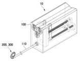
도 1은 본 발명의 일 실시예에 따른 전극 장치의 사시도이다.
도 2는 본 발명의 일 실시예에 따른 전극 장치의 내부사시도이다.
도 3은 전극 가이드부가 전극부를 가이드하여 관을 감싸도록 위치한 상태를 도시한 도면이다.
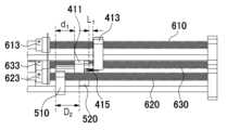
도 4는 본 발명의 일 실시예에 따른 전극 장치의 내부 구성요소를 나타낸 도면이다.
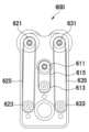
도 5는 본 발명의 일 실시예에 따른 전극 장치의 모터 연동부를 나타낸 도면이다.
도 6a 내지 도 6g는 본 발명의 일 실시예에 따른 전극 가이드의 동작 과정을 도시한 도면이다.
도 7a 내지 도 7g는 본 발명의 일 실시예에 따른 전극 구동부 및 전극 가이드 구동부의 동작 과정을 나타낸 도면이다.
도 8은 본 발명의 일 실시예에 따른 전극 장치의 마디부의 일부분을 나타낸 사시도이다.
도 9는 본 발명의 다른 실시예에 따른 전극 장치를 이용한 수술 로봇의 사시도이다.
도 10은 본 발명의 다른 실시예에 따른 수술 로봇의 로봇 팔에 결합되는 전극 장치를 나타낸 도면이다.FIG. 1 is a perspective view of an electrode device according to one embodiment of the present invention.
Figure 2 is an internal perspective view of an electrode device according to one embodiment of the present invention.
Figure 3 is a drawing showing a state in which the electrode guide part is positioned to guide the electrode part and surround the tube.
FIG. 4 is a drawing showing internal components of an electrode device according to one embodiment of the present invention.
FIG. 5 is a drawing showing a motor linkage of an electrode device according to one embodiment of the present invention.
FIGS. 6A to 6G are drawings illustrating the operation process of an electrode guide according to one embodiment of the present invention.
FIGS. 7A to 7G are drawings showing the operation process of an electrode driving unit and an electrode guide driving unit according to one embodiment of the present invention.
FIG. 8 is a perspective view showing a part of a joint portion of an electrode device according to one embodiment of the present invention.
FIG. 9 is a perspective view of a surgical robot using an electrode device according to another embodiment of the present invention.
FIG. 10 is a drawing showing an electrode device coupled to a robot arm of a surgical robot according to another embodiment of the present invention.
아래에서는 첨부한 도면을 참조하여 본 발명이 속하는 기술 분야에서 통상의 지식을 가진 자가 용이하게 실시할 수 있도록 본 발명의 실시예를 상세히 설명한다. 그러나 본 발명은 여러 가지 상이한 형태로 구현될 수 있으며 여기에서 설명하는 실시예에 한정되지 않는다. 그리고 도면에서 본 발명을 명확하게 설명하기 위해서 설명과 관계없는 부분은 생략하였으며, 명세서 전체를 통하여 유사한 부분에 대해서는 유사한 도면 부호를 붙였다.Hereinafter, with reference to the attached drawings, embodiments of the present invention will be described in detail so that those skilled in the art can easily practice the present invention. However, the present invention may be implemented in various different forms and is not limited to the embodiments described herein. In addition, in order to clearly describe the present invention in the drawings, parts that are not related to the description are omitted, and similar parts are assigned similar drawing reference numerals throughout the specification.
명세서 전체에서, 어떤 부분이 어떤 구성요소를 "포함"한다고 할 때, 이는 특별히 반대되는 기재가 없는 한 다른 구성요소를 제외하는 것이 아니라 다른 구성요소를 더 포함할 수 있는 것을 의미한다. 또한, 명세서 전체에서 어떤 부분이 다른 부분과 "연결"되어 있다고 할 때, 이는 직접적으로 연결되어 있는 경우뿐 아니라 중간에 다른 부재를 개재하여 연결되어 있는 경우와, 중간에 다른 소자를 사이에 전기적으로 연결되어 있는 경우도 포함한다. 나아가, 본원 명세서 전체에서, 어떤 부재가 다른 부재 "상에" 위치하고 있다고 할 때, 이는 어떤 부재가 다른 부재에 접해 있는 경우뿐 아니라 두 부재 사이에 또 다른 부재가 존재하는 경우도 포함한다. 또한, 본 명세서에서 사용된 "제1," "제2," 등의 표현들은 다양한 구성요소들을, 순서 및/또는 중요도에 상관없이 수식할 수 있고, 한 구성요소를 다른 구성요소와 구분하기 위해 사용될 뿐 해당 구성요소들을 한정하지 않으며, 반드시 다른 구성요소를 의미하는 것은 아니다. 예로서, '제1 방향'과 '제2 방향'은 동일한 방향을 의미할 수도 있고, 다른 방향을 의미할 수도 있다.Throughout the specification, when a part is said to "include" a component, this does not mean excluding other components, but rather including other components, unless otherwise specifically stated. In addition, throughout the specification, when a part is said to be "connected" to another part, this includes not only cases where they are directly connected, but also cases where they are connected through other components in between, and cases where other elements are electrically connected in between. Furthermore, throughout the specification, when a part is said to be "on" another part, this includes not only cases where a part is in contact with another part, but also cases where another part exists between the two parts. In addition, expressions such as "first," "second," etc. used herein can modify various components, regardless of order and/or importance, and are only used to distinguish one component from another component, and do not limit the components, and do not necessarily mean other components. For example, "first direction" and "second direction" may mean the same direction or different directions.
도 1은 본 발명의 일 실시예에 따른 전극 장치(10)의 사시도이고, 도 2는 본 발명의 일 실시예에 따른 전극 장치(10)의 내부사시도이며, 도 3은 전극 가이드부(300)가 전극부(200)를 가이드하여 관을 감싸도록 위치한 상태를 도시한 도면이고, 도 4는 본 발명의 일 실시예에 따른 전극 장치(10)의 내부 구성요소를 나타낸 도면이며, 도 5는 본 발명의 일 실시예에 따른 전극 장치(10)의 모터 연동부(600)를 나타낸 도면이고, 도 6a 내지 도 6g는 본 발명의 일 실시예에 따른 전극 가이드의 동작 과정을 도시한 도면이며, 도 7a 내지 도 7g는 본 발명의 일 실시예에 따른 전극 구동부(400) 및 전극 가이드 구동부(500)의 동작 과정을 나타낸 도면이고, 도 8은 본 발명의 일 실시예에 따른 전극 장치(10)의 마디부(310)의 일부분을 나타낸 사시도이다.FIG. 1 is a perspective view of an electrode device (10) according to an embodiment of the present invention, FIG. 2 is an internal perspective view of an electrode device (10) according to an embodiment of the present invention, FIG. 3 is a drawing illustrating a state in which an electrode guide part (300) is positioned to guide an electrode part (200) and surround a tube, FIG. 4 is a drawing illustrating internal components of an electrode device (10) according to an embodiment of the present invention, FIG. 5 is a drawing illustrating a motor linkage part (600) of an electrode device (10) according to an embodiment of the present invention, FIGS. 6A to 6G are drawings illustrating an operation process of an electrode guide according to an embodiment of the present invention, FIGS. 7A to 7G are drawings illustrating an operation process of an electrode drive part (400) and an electrode guide drive part (500) according to an embodiment of the present invention, and FIG. 8 is a perspective view illustrating a part of a joint part (310) of an electrode device (10) according to an embodiment of the present invention.
도 1 내지 도 4를 참조하면, 전극 장치(10)는 본체(100), 전극부(200), 전극 가이드부(300), 전극 구동부(400), 전극 가이드 구동부(500) 및 모터 연동부(600)를 포함할 수 있다.Referring to FIGS. 1 to 4, the electrode device (10) may include a main body (100), an electrode portion (200), an electrode guide portion (300), an electrode driving portion (400), an electrode guide driving portion (500), and a motor linkage portion (600).
본체(100)는 일방향으로 연장되는 샤프트(110)를 포함할 수 있다.The main body (100) may include a shaft (110) extending in one direction.
본체(100)의 내부에는 전극부(200)와 전극 가이드부(300)를 구동하고 제어하는 요소들이 배치될 수 있다. 예를 들어, 본체(100)의 내부에는 전극부(200)를 구동하고 제어하는 전극 구동부(400)와 전극 가이드부(300)를 구동하고 제어하는 전극 가이드 구동부(500)가 배치될 수 있다.Inside the main body (100), elements that drive and control the electrode unit (200) and the electrode guide unit (300) may be arranged. For example, inside the main body (100), an electrode driving unit (400) that drives and controls the electrode unit (200) and an electrode guide driving unit (500) that drives and controls the electrode guide unit (300) may be arranged.
전극부(200)는 샤프트(110)의 일단부로부터 인출되도록 형성되고, 시술자의 조작 등에 따라 체내의 관(V)을 포함하는 조직에 분포된 신경의 적어도 일부의 신경을 차단 또는 조절하도록 구성된다. 전극부(200)는 샤프트(110)의 내부에 수용되어 있다가, 전극 장치의 작동시 후술하는 전극 가이드부(300)에 의해 외부로 인출될 수 있다.The electrode part (200) is formed to be withdrawn from one end of the shaft (110) and is configured to block or control at least a portion of the nerves distributed in the tissue including the tube (V) in the body according to the manipulation of the operator, etc. The electrode part (200) is accommodated inside the shaft (110) and can be withdrawn to the outside by the electrode guide part (300) described later when the electrode device is in operation.
도 3을 참조하면, 전극부(200)는 베이스부(210) 에너지 전달부(220) 및 센서부(230)를 포함할 수 있다. 전극 장치(10)는 체내의 관(V) 또는 관(V) 형상의 조직의 외면을 전극이 감싸 에너지 전달부(220)를 통해 에너지를 전달할 수 있고, 이를 위해 베이스부(210)는 가요성의 연성 회로 기판일 수 있다.Referring to FIG. 3, the electrode part (200) may include a base part (210), an energy transmission part (220), and a sensor part (230). The electrode device (10) may transmit energy through the energy transmission part (220) by wrapping the outer surface of a tube (V) or a tube (V)-shaped tissue in the body with an electrode, and for this purpose, the base part (210) may be a flexible circuit board.
에너지 전달부(220)는 베이스부(210) 상에서 서로 평행하게 연장되는 두 전극으로 구성될 수 있다. 베이스부(210)와 에너지 전달부(220)는 체내의 관(V) 등을 원주 방향으로 연장되어 감싸도록 구성될 수 있다.The energy transfer unit (220) may be composed of two electrodes that extend parallel to each other on the base unit (210). The base unit (210) and the energy transfer unit (220) may be configured to extend in a circumferential direction and surround a tube (V) or the like in the body.
에너지 전달부(220)는 신경을 차단(block or denervation)하거나 조절(control or modulation)하기 위하여, 예를 들어, 스테인리스 스틸, 금 등과 같이 인체에 무해하며 전기를 전달할 수 있는 소재로 이루어질 수 있다.The energy transmission unit (220) may be made of a material that is harmless to the human body and can transmit electricity, such as stainless steel or gold, to block or denervate or control or modulate nerves.
또한, 에너지 전달부(220)는 에너지 소스 생성기로부터의 다양한 타입의 에너지를 전달할 수 있다. 예를 들어, 고주파 에너지(ratio-frequency(RF) energy), 전기 에너지, 레이저 에너지, 초음파 에너지(ultrasonic energy), 집속 초음파 에너지(high-intensity focused ultrasound energy), 극저온 에너지(cryogenic energy) 및 기타 열 에너지가 이용될 수 있다.Additionally, the energy transmission unit (220) can transmit various types of energy from the energy source generator. For example, ratio-frequency (RF) energy, electrical energy, laser energy, ultrasonic energy, high-intensity focused ultrasound energy, cryogenic energy, and other thermal energy can be used.
또한, 에너지 전달부(220)는 고주파 에너지 전달을 위한 연성 회로 기판(Flexible PCB), 초음파 에너지를 전달하기 위한 트렌스듀서, 높은 고전압 에너지를 전달하기 위한 금속 전극 등으로 구현되어 신경을 손상시키기 위한 에너지를 전달할 수 있다.In addition, the energy transmission unit (220) can be implemented with a flexible PCB for transmitting high-frequency energy, a transducer for transmitting ultrasonic energy, a metal electrode for transmitting high-voltage energy, etc., to transmit energy for damaging nerves.
또한, 베이스부(210) 상에는 센서부(230)가 형성될 수 있다. 예를 들어, 센서부(230)는 체내의 관(V) 등에 접촉하여 온도를 측정하는 열전대(thermocouple)일 수 있고, 센서부(230)는 전극 장치(10)에 의해 신경 절제 시술이 실시될 때, 시술 부위의 온도를 모니터링할 수 있다. 또한, 센서부(230)는 관의 신경의 신호를 측정할 수도 있다.In addition, a sensor unit (230) may be formed on the base unit (210). For example, the sensor unit (230) may be a thermocouple that measures temperature by contacting a tube (V) in the body, and the sensor unit (230) may monitor the temperature of the treatment site when a nerve ablation procedure is performed by the electrode device (10). In addition, the sensor unit (230) may also measure signals from the nerves of the tube.
센서부(230)는 예를 들어, 구리 및 콘스탄탄 쌍으로 구성된 열전대일 수 있다.The sensor unit (230) may be, for example, a thermocouple composed of a copper and constantan pair.
전극 가이드부(300)는 전극부(200)를 체내의 관(V)에 접촉시키는 기능을 수행할 수 있다.The electrode guide part (300) can perform the function of bringing the electrode part (200) into contact with a tube (V) in the body.
전극 가이드부(300)는 전극부(200)와 결합되고, 전극부(200)를 체내의 관(V)에 접촉시키는 와인딩 상태로 변형되도록 가이드할 수 있다.The electrode guide part (300) is combined with the electrode part (200) and can guide the electrode part (200) to be transformed into a winding state that brings it into contact with a tube (V) in the body.
도 3, 도 6a 내지 도 6g를 참조하면, 전극 가이드부(300)는 복수의 마디부(310)를 구비할 수 있다. 복수의 마디부(310)는 전극부(200)를 사이에 두고 체내의 관(V)의 둘레를 감싸도록 곡선의 와인딩 경로를 형성할 수 있다. 또한, 도 3에 도시된 상태가 곡선의 와인딩 경로를 따라 복수의 마디부(310)가 완전히 인출되어 배치된 상태일 수 있다.Referring to FIG. 3 and FIG. 6A to FIG. 6G, the electrode guide portion (300) may be provided with a plurality of joint portions (310). The plurality of joint portions (310) may form a curved winding path to wrap around the circumference of the tube (V) in the body with the electrode portion (200) in between. In addition, the state illustrated in FIG. 3 may be a state in which the plurality of joint portions (310) are completely pulled out and arranged along the curved winding path.
도 6a 내지 도 6g를 참조하면, 전극 가이드부(300)는 팁 조인트(330) 및 와이어(320)를 더 포함할 수 있다. 팁 조인트(330)는 전극부(200)를 지지하고, 순차적으로 연결된 복수의 마디부(310)의 말단에 결합될 수 있다.Referring to FIGS. 6A to 6G, the electrode guide portion (300) may further include a tip joint (330) and a wire (320). The tip joint (330) supports the electrode portion (200) and may be connected to the ends of a plurality of sequentially connected joint portions (310).
팁 조인트(330)는 복수의 마디부(310)보다 먼저 샤프트(110)의 일단부로부터 인출될 수 있다. 예를 들어, 팁 조인트(330)는 체내의 관(V)에 근접하도록 위치될 수 있고, 전극부(200)와의 간섭을 방지하거나 체내의 관(V)을 감싸는 면을 극대화화도록 말단으로 갈수록 폭 또는 두께가 얇아지는 테이퍼 형상을 가질 수 있다. 팁 조인트(330)에는 전극부(200)의 단부가 체결되어 고정될 수 있다.The tip joint (330) may be pulled out from one end of the shaft (110) before the plurality of joints (310). For example, the tip joint (330) may be positioned close to the tube (V) in the body, and may have a tapered shape in which the width or thickness becomes thinner toward the end to prevent interference with the electrode portion (200) or to maximize the surface area surrounding the tube (V) in the body. An end of the electrode portion (200) may be connected and fixed to the tip joint (330).
와이어(320)는 복수의 마디부(310)를 순차적으로 관통하도록 형성될 수 있다.The wire (320) can be formed to sequentially penetrate multiple joints (310).
도 8을 참조하면, 마디부(310)에는 와이어(320)의 관통을 위하여 길이 방향으로 와이어 홀(315)이 형성될 수 있다.Referring to FIG. 8, a wire hole (315) may be formed in the longitudinal direction in the joint portion (310) for the penetration of a wire (320).
와이어 홀(315)을 순차적으로 관통한 와이어(320)의 단부는 팁 조인트(330)에 결합되어 고정될 수 있고, 와이어(320)는 와이어 홀(315) 내에서 길이 방향으로 각 마디부(310)에 대해 슬라이딩 가능할 수 있다.The end of the wire (320) that sequentially passes through the wire hole (315) can be fixed by being joined to the tip joint (330), and the wire (320) can be slidable in the length direction for each joint portion (310) within the wire hole (315).
이에 따라, 와이어(320)는 복수의 마디부(310) 및 팁 조인트(330)가 와인딩 경로 상에 배치되도록 가이드하고, 복수의 마디부(310) 및 팁 조인트(330)를 관을 감는 방향으로 당기는 힘을 제공할 수 있다.Accordingly, the wire (320) can guide the plurality of joints (310) and tip joints (330) to be arranged on the winding path, and provide a force to pull the plurality of joints (310) and tip joints (330) in the direction of winding the tube.
와이어(320)는 복수의 마디부(310)와 함께 샤프트(110)의 일단부로부터 돌출되도록 동작될 수 있다. 이때, 마디부(310)가 돌출되는 양보다 와이어(320)가 돌출되는 양이 작도록 설계될 수 있어, 이에 의하여 와이어(320)는 복수의 마디부(310)를 곡선의 경로를 갖도록 당기는 힘을 제공할 수 있다.The wire (320) can be operated to protrude from one end of the shaft (110) together with a plurality of joints (310). At this time, the amount by which the wire (320) protrudes can be designed to be smaller than the amount by which the joints (310) protrude, thereby allowing the wire (320) to provide a force that pulls the plurality of joints (310) to have a curved path.
마디부(310)는 힌지부(311) 및 와인딩 지지부(313)를 구비할 수 있다. 힌지부(311)는 이웃하는 관절과 회전 가능한 연결을 위한 구성으로, 마디부(310)가 나란하게 연결되는 길이 방향으로 일측 또는 양측에 형성될 수 있다.The joint part (310) may be provided with a hinge part (311) and a winding support part (313). The hinge part (311) is configured for a rotational connection with an adjacent joint, and may be formed on one or both sides in the longitudinal direction in which the joint parts (310) are connected in parallel.
도 8에 도시되는 바와 같이, 힌지부(311)는 길이 방향과 교차하는 방향으로 회전축을 형성하여 이웃하는 마디부(310)의 힌지부(311)와 연결될 수 있다. 각 힌지부(311)에는 회전축이 형성되는 방향으로 힌지핀이 삽입되어 체결될 수 있다.As illustrated in Fig. 8, the hinge portion (311) may be connected to the hinge portion (311) of the neighboring joint portion (310) by forming a rotation axis in a direction intersecting the longitudinal direction. A hinge pin may be inserted and fastened into each hinge portion (311) in the direction in which the rotation axis is formed.
와인딩 지지부(313)는 와인딩 경로 상에 복수의 마디부(310)를 지지하기 위한 구성으로, 이웃하는 마디부(310)와 서로 지지되도록 길이 방향의 일측 또는 양측에 형성될 수 있다.The winding support member (313) is configured to support a plurality of joints (310) on the winding path, and can be formed on one or both sides in the longitudinal direction so as to support each other with neighboring joints (310).
도 3 및 도 8에 도시되는 바와 같이, 와인딩 지지부(313)는 전극 가이드의 내측 방향으로 힌지부(311)와 이웃하는 위치에 형성될 수 있다.As shown in FIG. 3 and FIG. 8, the winding support member (313) can be formed at a position adjacent to the hinge member (311) in the inner direction of the electrode guide.
와인딩 지지부(313)는, 예를 들면, 기설정된 각도 및 면적을 갖는 면으로 이루어질 수 있고, 이웃하는 와인딩 지지부(313)와 면 접촉되어 지지됨으로써, 전극 가이드부(300)의 와인딩된 형태가 고정될 수 있다.The winding support member (313) may be formed of, for example, a surface having a preset angle and area, and may be supported by being in surface contact with an adjacent winding support member (313), thereby fixing the wound shape of the electrode guide member (300).
와인딩 지지부(313) 및 와이어 홀(315)은 힌지부(311)의 회전 중심으로부터 체내의 관(V)을 향하는 내측으로 이격되는 위치에 형성될 수 있다.The winding support member (313) and the wire hole (315) can be formed at a position spaced inwardly from the center of rotation of the hinge member (311) toward the tube (V) in the body.
전극 가이드부(300)에 비해 상대적으로 와이어(320)가 후방으로 당겨지는 경우(와이어(320)가 샤프트(110)로부터 인출되는 길이가 마디부(310)에 비해 작은 경우), 와이어(320)에는 전극 가이드부(300)를 와인딩하는 방향으로 장력이 가해질 수 있다. 반면, 와인딩 지지부(313)는, 전극 가이드부(300)가 와인딩되는 것을 억제하는 방향으로 마디부(310) 서로를 지지하는 힘을 제공하고 있다. 와이어(320)와 와인딩 지지부(313)가 서로 반대 방향으로 힘의 균형을 이룸으로써, 전극 가이드부(300)가 와인딩 경로 상에서 고정될 수 있다.When the wire (320) is pulled rearward relative to the electrode guide portion (300) (when the length of the wire (320) pulled out from the shaft (110) is shorter than that of the joint portion (310), tension may be applied to the wire (320) in the direction of winding the electrode guide portion (300). On the other hand, the winding support portion (313) provides a force that supports the joint portions (310) in a direction that suppresses the electrode guide portion (300) from being wound. When the wire (320) and the winding support portion (313) achieve a balance of force in opposite directions, the electrode guide portion (300) can be fixed on the winding path.
또한, 전극 가이드부(300)는 제 1 마디군(317) 및 제 2 마디군(319)을 포함할 수 있다. 즉, 복수의 마디부(310)는 서로 다른 길이를 갖는 제 1 마디군(317)과 제 2 마디군(319)으로 나뉠 수 있다.In addition, the electrode guide portion (300) may include a first node group (317) and a second node group (319). That is, the plurality of node portions (310) may be divided into a first node group (317) and a second node group (319) having different lengths.
길이의 차이에 따라, 제 1 마디군(317)은 제1 곡률 반경을 형성하고, 제 2 마디군(319)은 제1 곡률 반경보다 큰 제2 곡률 반경을 형성할 수 있다. 예를 들어, 상대적으로 짧은 길이를 갖는 마디부들(제 1 마디군)이 작은 곡률 반경을 형성할 수 있고, 긴 길이를 갖는 마디부들(제 2 마디군)이 큰 곡률 반경을 형성할 수 있다.Depending on the difference in length, the first node group (317) can form a first radius of curvature, and the second node group (319) can form a second radius of curvature larger than the first radius of curvature. For example, node parts having a relatively short length (the first node group) can form a small radius of curvature, and node parts having a long length (the second node group) can form a large radius of curvature.
팁 조인트(330)에 가까운 측에 배치된 마디부(310)들에 의하여 더 작은 곡률 반경의 경로를 형성하게 되면, 체내의 관(V)과 샤프트(110) 사이의 공간으로 팁 조인트(330)가 진입되는 경로가 만들어질 수 있다. 그리고, 마디부(310)를 포함하는 전극 가이드부(300)가 전체적으로 나선형의 형상을 가질 수 있다.By forming a path with a smaller radius of curvature by the joints (310) arranged closer to the tip joint (330), a path can be created through which the tip joint (330) enters the space between the tube (V) and the shaft (110) in the body. In addition, the electrode guide part (300) including the joints (310) can have an overall spiral shape.
도 6a 내지 도 6g를 참조하면, 전극 가이드부(300)는 전극부(200)와 함께 샤프트(110)의 내부에 수용되어 있다가 시술을 위해 일단부로부터 전방을 향해 곡선의 와인딩 경로를 형성하면서 돌출될 수 있다.Referring to FIGS. 6A to 6G, the electrode guide portion (300) is accommodated inside the shaft (110) together with the electrode portion (200) and may be protruded from one end to the front to form a curved winding path for treatment.
예를 들어, 복수의 마디부(310)는 순차적으로 인출되면서 와이어(320)와의 변위 차이에 의하여, 곡선의 와인딩 경로를 따라 이동되어 전체적으로 관을 감싸는 상태가 될 수 있다.For example, multiple joints (310) may be sequentially pulled out and moved along a curved winding path by the difference in displacement with respect to the wire (320) to wrap the entire tube.
아울러, 전극 가이드부(300)는 관의 외주면과 이격되게 위치되고, 전극 가이드부(300)의 감겨진 내측에 배치되는 전극부(200)가 관의 외주면에 밀착될 수 있다.In addition, the electrode guide part (300) is positioned apart from the outer surface of the tube, and the electrode part (200) arranged on the wound inner side of the electrode guide part (300) can be in close contact with the outer surface of the tube.
복수의 마디부(310)는 전극 가이드 구동부(500)에 의하여 샤프트(110)로부터 인출되면서 관을 감싸는 방향으로 와인딩될 수 있다. 따라서, 전극 가이드부(300)가 동작하는 공간이 최소화될 수 있고, 협소한 공간에서도 안전하고 정확하게 신경을 차단 또는 조절하는 동작이 실시될 수 있다.The plurality of joints (310) can be wound in a direction that surrounds the tube while being pulled out from the shaft (110) by the electrode guide driving unit (500). Accordingly, the space in which the electrode guide unit (300) operates can be minimized, and an operation to safely and accurately block or control a nerve can be performed even in a narrow space.
한편, 전극부(200)는 전극 구동부(400)에 의하여 샤프트(110)로부터 인출되고 전극 가이드부(300)에 의해 관을 감싸는 방향으로 와인딩될 수 있다. 구체적으로, 전극부(200)는 전극 가이드부(300)와 함께 곡선의 와인딩 경로를 따라 전진하다가 샤프트(110)로부터 완전히 인출되어 배치된 상태일 때, 전극 구동부(400)의 제어에 의하여 체내의 관(V)에 서서히 밀착될 수 있다. 따라서, 전극부(200)는 체내의 관(V)을 손상시키지 않으면서 체내의 관(V)에 안정적으로 밀착되어 신경을 차단 또는 조절하는 동작이 실시될 수 있다.Meanwhile, the electrode part (200) can be drawn out from the shaft (110) by the electrode driving part (400) and can be wound in a direction that surrounds the tube by the electrode guide part (300). Specifically, the electrode part (200) can be gradually brought into close contact with the tube (V) inside the body by the control of the electrode driving part (400) when it is completely drawn out from the shaft (110) and positioned while advancing along the curved winding path together with the electrode guide part (300). Accordingly, the electrode part (200) can be stably brought into close contact with the tube (V) inside the body without damaging the tube (V) inside the body, thereby performing an operation of blocking or controlling a nerve.
도 4, 도 7a 내지 도 7g를 참조하면, 전극 구동부(400)는 복수의 모터를 통해 발생되는 회전량을 전달하는 모터 연동부(600)와 연결되어 전극부(200)를 전진 및 후진하도록 구성될 수 있다. 도 4에는 전극부(200) 및 전극 가이드부(300)의 도시가 생략되어 있다.Referring to FIG. 4 and FIG. 7a to FIG. 7g, the electrode driving unit (400) may be configured to move the electrode unit (200) forward and backward by being connected to a motor linkage unit (600) that transmits the amount of rotation generated through a plurality of motors. In FIG. 4, the electrode unit (200) and the electrode guide unit (300) are not depicted.
전극 구동부(400)는 전극부(200)에 장력을 제공하는 장력 유지 유닛(410)을 포함할 수 있고, 장력 유지 유닛(410)은 전극 연결부(411), 제 1 지지프레임(417), 전극 장력 조절 블록(413), 스프링부(415) 및 힘센서(미도시)를 포함할 수 있다.The electrode driving unit (400) may include a tension maintenance unit (410) that provides tension to the electrode unit (200), and the tension maintenance unit (410) may include an electrode connection unit (411), a first support frame (417), an electrode tension adjustment block (413), a spring unit (415), and a force sensor (not shown).
도 4에 도시되는 바와 같이, 전극 연결부(411)의 일단은 전극부(200)와 연결되고, 전극 연결부(411)의 타단은 전극 장력 조절 블록(413) 및 스프링부(415)와 연결될 수 있다. 보다 구체적으로, 전극 연결부(411)에 관통홀이 형성되어 전극 장력 조절 블록(413)의 일단이 삽입될 수 있고, 외측으로 돌출형성되어 스프링부(415)의 일단과 연결될 수 있도록 제 1 걸림홈(미도시)이 형성될 수 있다.As illustrated in FIG. 4, one end of the electrode connection portion (411) may be connected to the electrode portion (200), and the other end of the electrode connection portion (411) may be connected to the electrode tension adjustment block (413) and the spring portion (415). More specifically, a through hole may be formed in the electrode connection portion (411) so that one end of the electrode tension adjustment block (413) may be inserted, and a first engaging groove (not shown) may be formed so as to protrude outward and be connected to one end of the spring portion (415).
제 1 지지프레임(417)은 본체(100)의 내부에 고정되도록 설치될 수 있고, 전극 장력 조절 블록(413)이 삽입되어 제 1 지지프레임(417)의 외주면을 따라 슬라이딩될 수 있다.The first support frame (417) can be installed so as to be fixed to the inside of the main body (100), and the electrode tension adjustment block (413) can be inserted and slide along the outer surface of the first support frame (417).
제 1 지지프레임(417)에 전극 장력 조절 블록(413)이 삽입됨에 따라, 전극 장력 조절 블록(413)이 외부로 이탈되는 것을 방지하고, 전극 장력 조절 블록(413)의 이동방향을 고정시킬 수 있다.As the electrode tension control block (413) is inserted into the first support frame (417), the electrode tension control block (413) can be prevented from being detached to the outside, and the direction of movement of the electrode tension control block (413) can be fixed.
전극 장력 조절 블록(413)은 모터 연동부(600)와 결합된 제 1 회전축(610)을 통해 전진 및 후진하도록 구성될 수 있다. 여기서, 제 1 회전축(610)은 제 1 지지프레임(417)과 높이 방향으로 이격된 위치에 전후 방향으로 연장되도록 배치되고, 나사선이 형성될 수 있다.The electrode tension control block (413) can be configured to move forward and backward through a first rotational shaft (610) coupled with a motor linkage (600). Here, the first rotational shaft (610) is arranged to extend in the forward and backward direction at a position spaced apart in the height direction from the first support frame (417), and a screw line can be formed.
전극 장력 조절 블록(413)은 제 1 회전축(610)의 나사선과 맞물려 전진 및 후진될 수 있다.The electrode tension control block (413) can move forward and backward by engaging with the screw of the first rotation axis (610).
전극 장력 조절 블록(413)의 일단은 전극 연결부(411)의 관통홀에 삽입될 수 있도록 돌출형성될 수 있다. 이 때, 전극 장력 조절 블록(413)의 일단은 전극 장력 조절 블록(413)이 전극부(200)로 장력을 제공하기 위해 전극 장력 조절 블록(413)과 전극 연결부(411)의 거리가 증가하는 경우에 전극 장력 조절 블록(413)의 일단이 관통홀에서 이탈되지 않을 정도의 길이로 돌출형성될 수 있으며, 전극 장력 조절 블록(413) 일단의 끝단부에는 전극 연결부(411)가 이탈되는 것을 방지하는 스토퍼가 더 형성될 수도 있다.One end of the electrode tension control block (413) may be formed to protrude so that it can be inserted into the through-hole of the electrode connection portion (411). At this time, one end of the electrode tension control block (413) may be formed to protrude to a length that prevents one end of the electrode tension control block (413) from coming off the through-hole when the distance between the electrode tension control block (413) and the electrode connection portion (411) increases so that the electrode tension control block (413) provides tension to the electrode portion (200), and a stopper may be further formed at the end of one end of the electrode tension control block (413) to prevent the electrode connection portion (411) from coming off.
전극 장력 조절 블록(413)에는 제 1 걸림홈에 대향되는 위치에 스프링부(415)의 타단과 연결될 수 있도록 제 2 걸림홈(미도시)이 형성될 수 있다.A second engaging groove (not shown) may be formed in the electrode tension adjustment block (413) so as to be connected to the other end of the spring portion (415) at a position opposite to the first engaging groove.
스프링부(415)는 전극 연결부(411)와 전극 장력 조절 블록(413)을 연결하고, 전극부(200)에 장력을 제공할 수 있다.The spring part (415) connects the electrode connection part (411) and the electrode tension adjustment block (413) and can provide tension to the electrode part (200).
구체적으로, 스프링부(415)는 전극 연결부(411)의 제 1 걸림홈과 전극 장력 조절 블록(413)의 제 2 걸림홈에 연결되고, 모터 연동부(600)와 결합된 제 1 회전축(610)을 통하여 전극 장력 조절 블록(413)이 후진되는 경우에 전극부(200)에 장력을 제공할 수 있다.Specifically, the spring part (415) is connected to the first engaging groove of the electrode connection part (411) and the second engaging groove of the electrode tension adjustment block (413), and can provide tension to the electrode part (200) when the electrode tension adjustment block (413) moves backward through the first rotation shaft (610) coupled with the motor linkage (600).
힘센서는 스프링부(415)에 발생되는 장력을 감지할 수 있다. 구체적으로, 전극 장력 조절 블록(413)이 모터 연동부(600)와 결합된 제 1 회전축(610)을 통하여 후진되는 경우에 스프링부(415)에 장력이 발생되는데 이때, 스프링부(415)에 발생되는 장력을 감지할 수 있다.The force sensor can detect tension generated in the spring part (415). Specifically, when the electrode tension adjustment block (413) moves backwards through the first rotation shaft (610) coupled with the motor linkage (600), tension is generated in the spring part (415), and at this time, the tension generated in the spring part (415) can be detected.
힘센서는 장력이 발생된 이 후에 스프링부(415)의 복원력 또한 감지할 수 있다. 즉, 힘센서는 전극 장력 조절 블록(413)이 전후 방향으로 이동할 때 발생되는 장력 또는 복원력을 감지할 수 있다.The force sensor can also detect the restoring force of the spring part (415) after tension is generated. That is, the force sensor can detect the tension or restoring force generated when the electrode tension adjustment block (413) moves in the forward and backward direction.
한편, 도 4에 도시되는 바와 같이, 전극 가이드 구동부(500)는 전극 가이드와 연결되고 전극 가이드를 전진 및 후진하도록 구성될 수 있고, 제 2 지지프레임(511), 제 3 지지프레임(521), 로드 블록(510) 및 와이어 블록(520)을 포함할 수 있다.Meanwhile, as illustrated in FIG. 4, the electrode guide driving unit (500) may be configured to be connected to the electrode guide and move the electrode guide forward and backward, and may include a second support frame (511), a third support frame (521), a load block (510), and a wire block (520).
제 2 지지프레임(511)은 본체(100)의 내부에 고정되도록 설치될 수 있고, 로드 블록(510)이 삽입되어 제 2 지지프레임(511)의 외주면을 따라 슬라이딩될 수 있다.The second support frame (511) can be installed so as to be fixed to the inside of the main body (100), and a load block (510) can be inserted and slide along the outer surface of the second support frame (511).
제 2 지지프레임(511)에 로드 블록(510)이 삽입됨에 따라, 로드 블록(510)이 외부로 이탈되는 것을 방지하고, 로드 블록(510)의 이동방향을 고정시킬 수 있다.As the load block (510) is inserted into the second support frame (511), the load block (510) can be prevented from being dislodged to the outside and the direction of movement of the load block (510) can be fixed.
제 3 지지프레임(521)은 본체(100)의 내부에 고정되도록 설치될 수 있고, 와이어 블록(520)이 삽입되어 제 3 지지프레임(521)의 외주면을 따라 슬라이딩될 수 있다.The third support frame (521) can be installed so as to be fixed to the inside of the main body (100), and a wire block (520) can be inserted and slide along the outer surface of the third support frame (521).
제 3 지지프레임(521)에 와이어 블록(520)이 삽입됨에 따라, 와이어 블록(520)이 외부로 이탈되는 것을 방지하고, 와이어 블록(520)의 이동방향을 고정시킬 수 있다.As the wire block (520) is inserted into the third support frame (521), the wire block (520) can be prevented from being detached to the outside and the direction of movement of the wire block (520) can be fixed.
로드 블록(510)은 마디부(310)와 연결되고 모터 연동부(600)와 결합된 제 2 회전축(620)을 통해 전진 및 후진하도록 구성될 수 있다. 여기서, 제 2 회전축(620)은 제 2 지지프레임(511)과 높이 방향으로 이격된 위치에 전후 방향으로 연장되도록 배치되고, 나사선이 형성될 수 있다.The load block (510) can be configured to move forward and backward through a second rotational axis (620) connected to the joint (310) and coupled with a motor linkage (600). Here, the second rotational axis (620) is arranged to extend in the forward and backward direction at a position spaced apart in the height direction from the second support frame (511), and a screw line can be formed.
로드 블록(510)은 제 2 회전축(620)의 나사선과 맞물려 전진 및 후진될 수 있다.The load block (510) can move forward and backward by engaging with the screw of the second rotation axis (620).
와이어 블록(520)은 와이어(320)와 연결되고 모터 연동부(600)와 결합된 제 3 회전축(630)을 통해 전진 및 후진하도록 구성될 수 있다. 이 때, 제 3 회전축(630)은 제 3 지지프레임(521)과 높이 방향으로 이격된 위치에 전후 방향으로 연장되도록 배치되고, 나사선이 형성될 수 있다.The wire block (520) can be configured to move forward and backward through a third rotation axis (630) connected to the wire (320) and coupled with a motor linkage (600). At this time, the third rotation axis (630) is arranged to extend in the forward and backward direction at a position spaced apart in the height direction from the third support frame (521), and a screw thread can be formed.
와이어 블록(520)은 제 3 회전축(630)의 나사선과 맞물려 전진 및 후진될 수 있다.The wire block (520) can move forward and backward by engaging with the screw of the third rotation axis (630).
한편, 모터 연동부(600)는 전극 구동부(400) 및 전극 가이드 구동부(500)와 연결되고 복수의 모터를 통해 발생되는 회전량을 전극 구동부(400) 및 전극 가이드 구동부(500)로 전달할 수 있다.Meanwhile, the motor linkage (600) is connected to the electrode driving unit (400) and the electrode guide driving unit (500) and can transmit the rotation amount generated through multiple motors to the electrode driving unit (400) and the electrode guide driving unit (500).
여기서, 복수의 모터는 전극 장력 조절 블록(413)이 전진 및 후진하도록 회전량을 발생시키는 제 1 모터, 로드 블록(510)이 전진 및 후진하도록 회전량을 발생시키는 제 2 모터 및 와이어 블록(520)이 전진 및 후진하도록 회전량을 발생시키는 제 3 모터를 포함할 수 있다.Here, the plurality of motors may include a first motor that generates a rotation amount to move the electrode tension control block (413) forward and backward, a second motor that generates a rotation amount to move the load block (510) forward and backward, and a third motor that generates a rotation amount to move the wire block (520) forward and backward.
예를 들어, 도 4 내지 도 5에 도시되는 바와 같이, 제 1 모터(미도시)는 모터 연동부(600)에 형성된 제 1 모터 풀리(611)와 연결되고, 제 1 회전축(610)의 일단에는 제 1 회전축 풀리(613)가 형성되며, 제 1 모터 풀리(611)와 제 1 회전축 풀리(613)는 제 1 풀리 연결부재(615)로 연결될 수 있다. 이에 따라, 제 1 모터(미도시)가 작동하는 경우에 제 1 모터의 회전력은 제 1 모터 풀리(611), 제 1 풀리 연결부재(615) 및 제 1 회전축 풀리(613)를 통해 제 1 회전축(610)으로 전달되어 전극 장력 블록이 전진 및 후진될 수 있다.For example, as illustrated in FIGS. 4 and 5, a first motor (not shown) is connected to a first motor pulley (611) formed in a motor linkage (600), a first rotational shaft pulley (613) is formed at one end of a first rotational shaft (610), and the first motor pulley (611) and the first rotational shaft pulley (613) can be connected to a first pulley connecting member (615). Accordingly, when the first motor (not shown) operates, the rotational power of the first motor is transmitted to the first rotational shaft (610) through the first motor pulley (611), the first pulley connecting member (615), and the first rotational shaft pulley (613), so that the electrode tension block can move forward and backward.
또한, 제 2 모터(미도시)는 모터 연동부(600)에 형성된 제 2 모터 풀리(621)와 연결되고, 제 2 회전축(620)의 일단에는 제 2 회전축 풀리(623)가 형성되며, 제 2 모터 풀리(621)와 제 2 회전축 풀리(623)는 제 2 풀리 연결부재(625)로 연결될 수 있다. 이에 따라, 제 2 모터(미도시)가 작동하는 경우에 제 2 모터의 회전력은 제 2 모터 풀리(621), 제 2 풀리 연결부재(625) 및 제 2 회전축 풀리(623)를 통해 제 2 회전축(620)으로 전달되어 로드 블록(510)이 전진 및 후진될 수 있다.In addition, the second motor (not shown) is connected to the second motor pulley (621) formed in the motor linkage (600), the second rotational shaft pulley (623) is formed at one end of the second rotational shaft (620), and the second motor pulley (621) and the second rotational shaft pulley (623) can be connected to the second pulley connecting member (625). Accordingly, when the second motor (not shown) operates, the rotational power of the second motor is transmitted to the second rotational shaft (620) through the second motor pulley (621), the second pulley connecting member (625), and the second rotational shaft pulley (623), so that the load block (510) can move forward and backward.
또한, 제 3 모터(미도시)는 모터 연동부(600)에 형성된 제 3 모터 풀리(631)와 연결되고, 제 3 회전축(630)의 일단에는 제 3 회전축 풀리(633)가 형성되며, 제 3 모터 풀리(631)와 제 3 회전축 풀리(633)는 제 3 풀리 연결부재(635)로 연결될 수 있다. 이에 따라, 제 3 모터(미도시)가 작동하는 경우에 제 3 모터의 회전력은 제 3 모터 풀리(631), 제 3 풀리 연결부재(635) 및 제 3 회전축 풀리(633)를 통해 제 3 회전축(630)으로 전달되어 와이어 블록(520)이 전진 및 후진될 수 있다.In addition, the third motor (not shown) is connected to the third motor pulley (631) formed in the motor linkage (600), the third rotational axis pulley (633) is formed at one end of the third rotational axis (630), and the third motor pulley (631) and the third rotational axis pulley (633) can be connected to the third pulley connecting member (635). Accordingly, when the third motor (not shown) operates, the rotational power of the third motor is transmitted to the third rotational axis (630) through the third motor pulley (631), the third pulley connecting member (635), and the third rotational axis pulley (633), so that the wire block (520) can move forward and backward.
이처럼, 전극 장력 조절 블록(413), 로드 블록(510) 및 와이어 블록(520)이 각각의 모터(미도시)로 전진 및 후진됨에 따라, 전극부(200)가 관의 외벽에 밀착될 때 정밀하게 동작될 수 있다.In this way, as the electrode tension control block (413), load block (510), and wire block (520) are moved forward and backward by their respective motors (not shown), the electrode part (200) can be precisely operated when it is in close contact with the outer wall of the tube.
또한, 모터 연동부(600)에 기존 수술 로봇(1)에 구비되는 관절 조작용 복수의 모터가 연동 가능하여 전극 장치(10)의 구조 변경 없이 다양한 수술 로봇(1)에 결합하여 사용할 수 있다.In addition, multiple motors for joint manipulation equipped in an existing surgical robot (1) can be linked to the motor linkage (600), so that the electrode device (10) can be combined and used with various surgical robots (1) without changing the structure.
이하, 도 7a 내지 도 7g를 참조하여 전극 구동부(400) 및 전극 가이드 구동부(500)에 의한 전극부(200) 및 전극 가이드부(300)의 구동을 살펴보도록 한다. 도 7a 내지 도 7g는 도 6a 내지 도 6g의 상태에 대응되는 상태일 수 있다.Hereinafter, the driving of the electrode unit (200) and the electrode guide unit (300) by the electrode driving unit (400) and the electrode guide driving unit (500) will be examined with reference to FIGS. 7a to 7g. FIGS. 7a to 7g may be states corresponding to the states of FIGS. 6a to 6g.
도 7a의 전극 구동부(400) 및 전극 가이드 구동부(500)는 전진 이동을 시작하기 직전이거나, 후진 이동이 끝난 직후일 수 있다. 따라서, 도 6a에 도시되는 바와 같이, 전극부(200)와 전극 가이드부(300)는 체내의 관(V)의 둘레를 감싸기 직전이거나 체내의 관(V)의 둘레를 감싼 이후 감싸기 전 상태로 이동한 직후일 수 있다. 즉, 전극 장치(10)에 의해 신경 절제 시술이 실시되기 직전이거나 실시된 직후일 수 있다.The electrode driving unit (400) and the electrode guide driving unit (500) of Fig. 7a may be just before starting forward movement or just after finishing backward movement. Accordingly, as shown in Fig. 6a, the electrode unit (200) and the electrode guide unit (300) may be just before wrapping around the circumference of the tube (V) in the body or just after moving to a state before wrapping after wrapping around the circumference of the tube (V) in the body. In other words, it may be just before or just after performing a nerve ablation procedure by the electrode device (10).
여기서, 로드 블록(510)과 와이어 블록(520) 사이의 초기 거리는 일 예로 'D1'일 수 있고, 로드 블록(510)과 전극 연결부(411) 사이의 초기 거리는 일 예로 'd0'일 수 있다. 또한, 스프링부(415)의 길이는 스프링부(415)의 길이 변화가 없는 상태, 일 예로 'L1'일 수 있으며, 힘센서를 통해 측정된 힘(F)도 '0'일 수 있다.Here, the initial distance between the load block (510) and the wire block (520) may be, for example, 'D1', and the initial distance between the load block (510) and the electrode connection part (411) may be, for example, 'd0'. In addition, the length of the spring part (415) may be a state in which there is no change in the length of the spring part (415), for example, 'L1', and the force (F) measured by the force sensor may also be '0'.
도 7b를 참조하면, 전극 가이드 구동부(500)는 모터 연동부(600)와 연결되어 모터를 통해 전진 이동할 수 있고, 전극 가이드 구동부(500)가 전진할 때, 전극 장력 조절 블록(413)이 함께 전진할 수 있다.Referring to FIG. 7b, the electrode guide driving unit (500) is connected to the motor linkage unit (600) and can move forward via the motor, and when the electrode guide driving unit (500) moves forward, the electrode tension adjustment block (413) can move forward together.
전극 가이드 구동부(500) 및 전극 장력 조절 블록(413)의 전진에 의해, 도 6b에 도시되는 바와 같이, 전극부(200)와 전극 가이드부(300)는 샤프트(110)로부터 전방을 향해 인출되어 체내의 관(V)의 둘레를 감싸도록 와인딩 상태로 변형될 수 있다.By advancing the electrode guide driving unit (500) and the electrode tension control block (413), as shown in FIG. 6B, the electrode unit (200) and the electrode guide unit (300) can be drawn forward from the shaft (110) and transformed into a winding state to wrap around the circumference of the tube (V) in the body.
구체적으로, 전극 장력 조절 블록(413)은 제 1 지지프레임(417)이 제공하는 경로에 따라 제 1 모터(미도시)와 연결된 제 1 회전축(610)을 통해 전진 이동할 수 있고, 로드 블록(510)은 제 2 지지프레임(511)이 제공하는 경로에 따라 제 2 모터와 연결된 제 2 회전축(620)을 통해 전진 이동할 수 있으며, 와이어 블록(520)은 제 3 지지프레임(521)이 제공하는 경로에 따라 제 3 모터와 연결된 제 3 회전축(630)을 통해 전진 이동할 수 있다.Specifically, the electrode tension control block (413) can move forward through the first rotation axis (610) connected to the first motor (not shown) along a path provided by the first support frame (417), the load block (510) can move forward through the second rotation axis (620) connected to the second motor along a path provided by the second support frame (511), and the wire block (520) can move forward through the third rotation axis (630) connected to the third motor along a path provided by the third support frame (521).
이에 따라, 전극 가이드 구동부(500)와 연결된 전극 가이드부(300)가 샤프트(110)로부터 전방을 향해 인출되고, 전극 연결부(411)에 일단이 연결된 전극부(200) 또한 샤프트(110)로부터 인출될 수 있다.Accordingly, the electrode guide part (300) connected to the electrode guide driving part (500) is pulled out forward from the shaft (110), and the electrode part (200) with one end connected to the electrode connecting part (411) can also be pulled out from the shaft (110).
전극 가이드 구동부(500)가 전진할 때, 제 2 회전축(620)의 제 1 회전수가 제 3 회전축(630)의 제 2 회전수보다 높게 설정되어 로드 블록(510)이 와이어 블록(520)보다 더 전진할 수 있다.When the electrode guide driving unit (500) moves forward, the first rotational speed of the second rotational axis (620) is set higher than the second rotational speed of the third rotational axis (630), so that the load block (510) can move forward further than the wire block (520).
예를 들어, 도 6b에 도시되는 바와 같이, 제 2 모터의 회전량을 제 3 모터의 회전량보다 크도록 설정하여, 제 2 모터(미도시)와 연결된 제 2 회전축(620)의 제 1 회전수만큼 전진 이동하는 로드 블록(510)과 제 3 모터와 연결된 제 3 회전축(630)의 제 2 회전수만큼 전진 이동하는 와이어 블록(520) 사이의 거리는 'D2'로 증가 될 수 있다.For example, as illustrated in FIG. 6b, by setting the rotational amount of the second motor to be greater than the rotational amount of the third motor, the distance between the load block (510) that moves forward by the first rotational number of the second rotational shaft (620) connected to the second motor (not illustrated) and the wire block (520) that moves forward by the second rotational number of the third rotational shaft (630) connected to the third motor can be increased to 'D2'.
또한, 제 1 회전축(610)의 제 3 회전수는 제 3 회전축(630)의 제 2 회전수보다 낮게 설정됨에 따라, 전극 구동부(400) 및 전극 가이드 구동부(500)가 전진할 때, 전극 장력 조절 블록(413), 로드 블록(510) 및 와이어 블록(520)의 전전 거리는 상이할 수 있다.In addition, since the third rotational speed of the first rotational axis (610) is set lower than the second rotational speed of the third rotational axis (630), when the electrode driving unit (400) and the electrode guide driving unit (500) advance, the forward distances of the electrode tension control block (413), the load block (510), and the wire block (520) may be different.
예를 들어, 도 6a 내지 6b에 도시되는 바와 같이, 제 3 모터의 회전량을 제 1 모터의 회전량보다 크도록 설정하고, 전술한 바와 같이, 제 2 회전축(620)의 제 1 회전수는 제 3 회전축(630)의 제 2 회전수보다 높게 설정되므로, 제 2 모터(미도시)와 연결된 제 2 회전축(620)의 제 1 회전수만큼 전진 이동하는 로드 블록(510)과 제 1 모터와 연결된 제 1 회전축(610)의 제 3 회전수만큼 전진이동하는 전극 장력 조절 블록(413)에 스프링부(415)로 연결된 전극 연결부(411) 사이의 거리는 'd1'로 증가될 수 있다.For example, as illustrated in FIGS. 6A to 6B, since the rotational amount of the third motor is set to be greater than the rotational amount of the first motor, and as described above, the first rotational speed of the second rotational shaft (620) is set to be higher than the second rotational speed of the third rotational shaft (630), the distance between the load block (510) that moves forward by the first rotational speed of the second rotational shaft (620) connected to the second motor (not illustrated) and the electrode tension control block (413) that moves forward by the third rotational speed of the first rotational shaft (610) connected to the first motor can be increased to 'd1'.
또한, 스프링부(415)의 길이는 스프링부(415)의 길이 변화가 없는 상태, 일 예로 'L1'일 수 있으며, 힘센서(미도시)를 통해 측정된 힘(F)도 '0'일 수 있다.In addition, the length of the spring part (415) may be in a state where there is no change in the length of the spring part (415), for example, 'L1', and the force (F) measured through the force sensor (not shown) may also be '0'.
도 7c를 참조하면, 전극 가이드 구동부(500)는 정지상태를 유지하고 전극 장력 조절 블록(413)은 제 1 모터와 연결된 제 1 회전축(610)을 통해 후진 이동될 수 있다.Referring to FIG. 7c, the electrode guide driving unit (500) is maintained in a stationary state, and the electrode tension adjustment block (413) can be moved backward through the first rotation shaft (610) connected to the first motor.
여기서, 로드 블록(510)과 와이어 블록(520) 사이의 거리는 전진 이동된 위치에서 정지상태를 유지하므로, 'D2'일 수 있다. 또한, 로드 블록(510)은 정지상태를 유지하고, 전극 장력 조절 블록(413)은 제 1 모터와 연결된 제 1 회전축(610)을 통해 후진 이동될 수 있으므로, 로드 블록(510)과 전극 장력 조절 블록(413)에 스프링부(415)로 연결된 전극 연결부(411) 사이의 거리는 'd2'로 증가될 수 있다. 여기서, 증가된 거리, 'd2'는 전극부(200)와 접촉된 관의 직경에 반비례할 수 있다.Here, the distance between the load block (510) and the wire block (520) may be 'D2' since the distance is maintained in a stationary state at the forwardly moved position. In addition, since the load block (510) is maintained in a stationary state and the electrode tension adjustment block (413) can be moved backward through the first rotation shaft (610) connected to the first motor, the distance between the load block (510) and the electrode connection part (411) connected to the electrode tension adjustment block (413) by the spring part (415) may be increased to 'd2'. Here, the increased distance, 'd2', may be inversely proportional to the diameter of the tube in contact with the electrode part (200).
또한, 스프링부(415)의 길이는 스프링부(415)의 길이 변화가 없는 상태, 'L1'일 수 있으며, 힘센서를 통해 측정된 힘(F)도 '0'일 수 있다.In addition, the length of the spring part (415) may be 'L1', which is a state where there is no change in the length of the spring part (415), and the force (F) measured through the force sensor may also be '0'.
증가된 거리 'd2'에 의해 도 6c에 도시되는 바와 같이, 스프링부(415)의 길이 변화가 없는 상태로 전극부(200)가 체내의 관(V)에 접촉될 수 있다.As shown in Fig. 6c, by the increased distance 'd2', the electrode part (200) can be brought into contact with the tube (V) inside the body without any change in the length of the spring part (415).
도 7d를 참조하면, 전극 가이드 구동부(500)는 정지상태를 유지하고 전극 장력 조절 블록(413)은 제 1 모터와 연결된 제 1 회전축(610)을 통해 더 후진 이동되어 스프링부(415)의 길이가 연장될 수 있다.Referring to FIG. 7d, the electrode guide driving unit (500) is maintained in a stationary state, and the electrode tension adjustment block (413) is moved further backward through the first rotation shaft (610) connected to the first motor, so that the length of the spring unit (415) can be extended.
구체적으로, 로드 블록(510)과 와이어 블록(520) 사이의 거리는 전진 이동된 위치에서 정지상태를 유지하므로, 'D2'일 수 있다. 또한, 전극 연결부(411)는 일단이 체내의 관(V)에 접촉된 전극부(200)와 연결되어 정지상태를 유지하므로, 로드 블록(510)과 전극 연결부(411) 사이의 거리는 'd2'일 수 있다.Specifically, the distance between the load block (510) and the wire block (520) may be 'D2' because it maintains a stationary state at the forwardly moved position. In addition, since the electrode connection part (411) is connected to the electrode part (200) that has one end in contact with the tube (V) in the body and maintains a stationary state, the distance between the load block (510) and the electrode connection part (411) may be 'd2'.
또한, 전극 장력 조절 블록(413)은 제 1 모터와 연결된 제 1 회전축(610)을 통해 더 후진 이동하여 전극 연결부(411)와 전극 장력 조절 블록(413)을 연결하는 스프링부(415)의 길이는 증가될 수 있다.In addition, the electrode tension adjustment block (413) can be moved further backward through the first rotation shaft (610) connected to the first motor, so that the length of the spring part (415) connecting the electrode connection part (411) and the electrode tension adjustment block (413) can be increased.
스프링부(415)의 길이는 스프링부(415)의 길이가 증가된 상태, 일 예로 'L2'일 수 있으며, 힘센서를 통해 측정된 힘이 발생될 수 있다.The length of the spring part (415) may be increased, for example, 'L2', and a force measured by the force sensor may be generated.
힘센서를 통해 측정된 힘은 스프링부(415)의 길이가 일정 거리 증가되면서 생성된 장력일 수 있다.The force measured by the force sensor may be a tension generated as the length of the spring part (415) increases by a certain distance.
이처럼, 전극 가이드 구동부(500)는 정지상태를 유지하고 전극 장력 조절 블록(413)은 더 후진 이동되어 스프링부(415)의 길이가 연장됨에 따라, 체내의 관(V)에 일정 장력으로 밀착된 전극부(200)는 신경을 손상시키기 위한 에너지를 전달하여 신경 절제 시술을 실시할 수 있다.In this way, the electrode guide driving unit (500) is maintained in a stationary state, and the electrode tension adjustment block (413) moves further backward so that the length of the spring unit (415) is extended, so that the electrode unit (200) that is pressed against the tube (V) inside the body with a certain tension transmits energy to damage the nerve, thereby enabling a nerve ablation procedure to be performed.
이 후, 도 7e를 참조하면, 전극 가이드 구동부(500)는 정지상태를 유지하고, 전극 장력 조절 블록(413)은 제 1 모터와 연결된 제 1 회전축(610)을 통해 도 7d에서 후진 이동한 만큼 전진 이동되어 스프링부(415)의 상태를 되돌릴 수 있다.After this, referring to FIG. 7e, the electrode guide driving unit (500) maintains a stationary state, and the electrode tension adjustment block (413) moves forward as much as it moved backward in FIG. 7d through the first rotation shaft (610) connected to the first motor, thereby restoring the state of the spring unit (415).
구체적으로, 로드 블록(510)과 와이어 블록(520) 사이의 거리는 전진 이동된 위치에서 정지상태를 유지하므로, 'D2'일 수 있고, 전극 연결부(411)는 정지상태를 유지하므로, 로드 블록(510)과 전극 연결부(411) 사이의 거리는 'd2'일 수 있다. 또한, 전극 장력 조절 블록(413)이 제 1 모터와 연결된 제 1 회전축(610)을 통해 전술한 후진 이동만큼 전진 이동함으로써, 스프링부(415)의 길이가 다시 일정 길이로 감소될 수 있다.Specifically, the distance between the load block (510) and the wire block (520) may be 'D2' because the distance is maintained in a stationary state at the forwardly moved position, and the electrode connection portion (411) may be 'd2' because the distance between the load block (510) and the electrode connection portion (411) is maintained in a stationary state. In addition, since the electrode tension adjustment block (413) moves forward by the amount of the aforementioned backward movement through the first rotation shaft (610) connected to the first motor, the length of the spring portion (415) may be reduced to a constant length again.
따라서, 스프링부(415)에 생성되었던 장력이 모두 감소되어 도 6e에 도시되는 바와 같이, 스프링부(415)의 길이 변화가 없는 상태로 전극부(200)가 체내의 관(V)에 접촉될 수 있다. 그러므로, 스프링부(415)의 길이는 스프링부(415)의 길이 변화가 없는 상태, 'L1'일 수 있으며, 힘센서를 통해 측정된 힘(F)도 '0'일 수 있다.Accordingly, the tension generated in the spring portion (415) is completely reduced, and as shown in Fig. 6e, the electrode portion (200) can be brought into contact with the tube (V) inside the body without any change in the length of the spring portion (415). Therefore, the length of the spring portion (415) can be 'L1', that is, without any change in the length of the spring portion (415), and the force (F) measured by the force sensor can also be '0'.
도 7f를 참조하면, 전극 가이드 구동부(500)는 정지상태를 유지하고, 전극 장력 조절 블록(413)은 제 1 모터와 연결된 제 1 회전축(610)을 통해 도 7c에서 후진 이동한 만큼 전진 이동될 수 있다.Referring to FIG. 7f, the electrode guide driving unit (500) remains stationary, and the electrode tension control block (413) can move forward as much as it moved backward in FIG. 7c through the first rotation shaft (610) connected to the first motor.
구체적으로, 로드 블록(510)과 와이어 블록(520) 사이의 거리는 전진 이동된 위치에서 정지상태를 유지하므로, 'D2'일 수 있고, 로드 블록(510)과 전극 장력 조절 블록(413)에 스프링부(415)로 연결된 전극 연결부(411) 사이의 거리는 'd1'으로 복귀될 수 있다. 스프링부(415)의 길이는 스프링부(415)의 길이 변화가 없는 상태, 'L1'일 수 있으며, 힘센서를 통해 측정된 힘(F)도 '0'일 수 있다.Specifically, the distance between the load block (510) and the wire block (520) can be 'D2' because it remains stationary at the forward-moved position, and the distance between the load block (510) and the electrode connection part (411) connected to the electrode tension adjustment block (413) by the spring part (415) can be returned to 'd1'. The length of the spring part (415) can be 'L1', which is a state where there is no change in the length of the spring part (415), and the force (F) measured by the force sensor can also be '0'.
또한, 전극 가이드부(300)와 이격되어 체내의 관(V)에 밀착되었던 전극부(200)는 다시 전극 가이드부(300)에 밀접될 수 있다.In addition, the electrode part (200) that was spaced apart from the electrode guide part (300) and in close contact with the tube (V) inside the body can be brought into close contact with the electrode guide part (300) again.
전극 구동부(400) 및 전극 가이드 구동부(500)의 후진 이동이 완료되면, 도 7g에 도시되는 바와 같이, 로드 블록(510)과 와이어 블록(520) 사이의 거리는 'D1'일 수 있고, 로드 블록(510)과 전극 연결부(411) 사이의 거리는 'd0'일 수 있다. 또한, 스프링부(415)의 길이는 스프링부(415)의 길이 변화가 없는 상태, 'L1'일 수 있으며, 힘센서를 통해 측정된 힘(F)도 '0'일 수 있다.When the backward movement of the electrode driving unit (400) and the electrode guide driving unit (500) is completed, as shown in FIG. 7g, the distance between the load block (510) and the wire block (520) may be 'D1', and the distance between the load block (510) and the electrode connecting unit (411) may be 'd0'. In addition, the length of the spring unit (415) may be 'L1', which is a state where there is no change in the length of the spring unit (415), and the force (F) measured by the force sensor may also be '0'.
이때, 도 7g는 도 7a와 동일한 상태로 전극 구동부(400) 및 전극 가이드 구동부(500)는 전진 이동을 시작하기 직전이거나, 후진 이동이 끝난 직후일 수 있다. 따라서, 도 6g에 도시되는 바와 같이, 전극부(200)와 전극 가이드부(300)는 체내의 관(V)의 둘레를 감싸기 직전이거나 체내의 관(V)의 둘레를 감싼 이후 감싸기 전 상태로 이동한 직후일 수 있다. 즉, 전극 장치(10)에 의해 신경 절제 시술이 실시되기 직전이거나 실시된 직후일 수 있다.At this time, Fig. 7g may be in the same state as Fig. 7a, and the electrode driving unit (400) and the electrode guide driving unit (500) may be just before starting forward movement or just after finishing backward movement. Accordingly, as shown in Fig. 6g, the electrode unit (200) and the electrode guide unit (300) may be just before wrapping around the circumference of the tube (V) in the body or may be just after moving to a state before wrapping after wrapping around the circumference of the tube (V) in the body. In other words, it may be just before or just after performing a nerve ablation procedure by the electrode device (10).
도 9는 본 발명의 다른 실시예에 따른 전극 장치(10)를 이용한 수술 로봇(1)의 사시도이고, 도 10은 본 발명의 다른 실시예에 따른 수술 로봇(1)의 로봇 팔(20)에 결합되는 전극 장치(10)를 나타낸 도면이다.FIG. 9 is a perspective view of a surgical robot (1) using an electrode device (10) according to another embodiment of the present invention, and FIG. 10 is a drawing showing an electrode device (10) coupled to a robot arm (20) of a surgical robot (1) according to another embodiment of the present invention.
도 9 내지 도 10에 도시되는 바와 같이, 본 발명의 일 실시예에 따른 전극 장치(10)를 이용한 수술 로봇(1)은 전극 장치(10), 로봇 팔(20) 및 로봇 팔(20)을 지지하는 본체부(30)를 포함할 수 있다.As illustrated in FIGS. 9 and 10, a surgical robot (1) using an electrode device (10) according to one embodiment of the present invention may include an electrode device (10), a robot arm (20), and a main body (30) supporting the robot arm (20).
로봇 팔(20)은 모터 연동부(600)를 통해 전극 구동부(400) 및 전극 가이드 구동부(500)로 회전량을 전달하는 복수의 모터를 포함할 수 있다.The robot arm (20) may include a plurality of motors that transmit rotational amount to the electrode driving unit (400) and the electrode guide driving unit (500) through the motor linkage unit (600).
복수의 모터는 전극 장력 조절 블록(413)이 전진 및 후진하도록 회전량을 발생시키는 제 1 모터(미도시), 로드 블록(510)이 전진 및 후진하도록 회전량을 발생시키는 제 2 모터(미도시) 및 와이어 블록(520)이 전진 및 후진하도록 회전량을 발생시키는 제 3 모터(미도시)를 포함할 수 있다.The multiple motors may include a first motor (not shown) that generates a rotation amount to move the electrode tension control block (413) forward and backward, a second motor (not shown) that generates a rotation amount to move the load block (510) forward and backward, and a third motor (not shown) that generates a rotation amount to move the wire block (520) forward and backward.
수술 로봇(1)은 제어부를 더 포함할 수 있다.The surgical robot (1) may further include a control unit.
제어부는 수술부위의 영상을 표시하는 디스플레이, 로봇 팔(20)의 동작을 제어하는 제 1 조이스틱, 전극 장치(10)의 동작을 제어하는 한 쌍의 손잡이부 및 전극 장치(10)의 동작을 제어하는 한 쌍의 페달을 포함할 수 있다.The control unit may include a display for displaying an image of the surgical site, a first joystick for controlling the operation of the robotic arm (20), a pair of handles for controlling the operation of the electrode device (10), and a pair of pedals for controlling the operation of the electrode device (10).
그러나 이와 같은 제어부는 로봇 팔(20), 전극 장치(10)를 사용자의 의사에 따라 동작시킬 수 있도록 하는 것이라면 한정하지 않고 다양하게 그 구성이 변경될 수 있다.However, the control unit may be configured in various ways without limitation as long as it can operate the robot arm (20) and electrode device (10) according to the user's intention.
전술한 바와 같이, 본 발명의 일 실시예에 따른 전극 장치(10)에 의하면, 전극 가이드부(300)가 체내의 관(V)에 밀접하도록 위치된 후 전극부(200)를 관의 외벽에 서서히 밀착시킴으로써, 외부의 자극에 쉽게 손상될 수 있는 체내의 관(V)을 손상시키지 않으면서 전극이 형성된 구성 요소를 관의 외벽에 안전하게 밀착시킬 수 있게 된다.As described above, according to the electrode device (10) according to one embodiment of the present invention, after the electrode guide part (300) is positioned in close contact with the tube (V) inside the body, the electrode part (200) is slowly brought into close contact with the outer wall of the tube, so that the component on which the electrode is formed can be safely brought into close contact with the outer wall of the tube without damaging the tube (V) inside the body, which can be easily damaged by external stimulation.
또한, 전극 장치(10)는 복수의 모터(미도시)를 통해 전극 구동부(400)와 전극 가이드 구동부(500)로 각각 회전량을 전달하는 모터 연동부(600)를 통하여, 전극부(200)가 관의 외벽에 밀착시킬 때 정밀하게 동작되도록 할 수 있고, 전극 장치(10)의 구조 변경 없이 다양한 수술 로봇(1)에 구비되는 관절 조작용 모터에 결합하여 사용할 수 있게 된다.In addition, the electrode device (10) can be precisely operated when the electrode part (200) is pressed against the outer wall of the tube through a motor linkage (600) that transmits the rotation amount to the electrode driving part (400) and the electrode guide driving part (500) through a plurality of motors (not shown), and can be used by being combined with a joint manipulation motor equipped in various surgical robots (1) without changing the structure of the electrode device (10).
이상에서 설명한 본 발명의 설명은 예시를 위한 것이며, 본 발명이 속하는 기술분야의 통상의 지식을 가진 자는 본 발명의 기술적 사상이나 필수적인 특징을 변경하지 않고서 다른 구체적인 형태로 쉽게 변형이 가능하다는 것을 이해할 수 있을 것이다. 그러므로 이상에서 기술한 실시예들은 모든 면에서 예시적인 것이며 한정적이 아닌 것으로 이해해야만 한다. 예를 들어, 단일형으로 설명되어 있는 각 구성 요소는 분산되어 실시될 수도 있으며, 마찬가지로 분산된 것으로 설명되어 있는 구성 요소들도 결합된 형태로 실시될 수 있다.The description of the present invention described above is for illustrative purposes, and those skilled in the art to which the present invention pertains will understand that it can be easily modified into other specific forms without changing the technical idea or essential features of the present invention. Therefore, it should be understood that the embodiments described above are exemplary in all respects and not restrictive. For example, each component described as a single type may be implemented in a distributed manner, and likewise, components described as distributed may be implemented in a combined form.
또한, 본 발명의 범위는 상기 상세한 설명보다는 후술하는 청구범위에 의하여 나타내어지며, 청구범위의 의미 및 범위 그리고 그 균등 개념으로부터 도출되는 모든 변경 또는 변형된 형태가 본 발명의 범위에 포함되는 것으로 해석되어야 한다.In addition, the scope of the present invention is indicated by the claims described below rather than the above detailed description, and all changes or modifications derived from the meaning and scope of the claims and their equivalent concepts should be interpreted as being included in the scope of the present invention.
V : 관 또는 조직
1 : 수술 로봇
10 : 전극 장치
20 : 로봇 팔
30 : 본체부
100 : 본체
110 : 샤프트
200 : 전극부
210 : 베이스부
220 : 에너지 전달부
230 : 센서부
300 : 전극 가이드부
310 : 마디부
311 : 힌지부
313 : 와인딩 지지부
315 : 와이어 홀
317 : 제 1 마디군
319 : 제 2 마디군
320 : 와이어
330 : 팁 조인트
400 : 전극 구동부
410 : 장력 유지 유닛
411 : 전극 연결부
413 : 전극 장력 조절 블록
415 : 스프링부
500 : 전극 가이드 구동부
510 : 로드 블록
520 : 와이어 블록
600 : 모터 연동부
610 : 제 1 회전축
611 : 제 1 모터 풀리
613 : 제 1 회전축 풀리
615 : 제 1 풀리 연결부재
620 : 제 2 회전축
621 : 제 2 모터 풀리
623 : 제 2 회전축 풀리
625 : 제 2 풀리 연결부재
630 : 제 3 회전축
631 : 제 3 모터 풀리
633 : 제 3 회전축 풀리
635 : 제 3 풀리 연결부재V: tube or tissue
1: Surgical Robot
10: Electrode device
20 : Robot Arm
30 : Main body
100 : Body
110 : Shaft
200 : Electrode section
210 : Bass section
220: Energy transfer section
230 : Sensor section
300 : Electrode guide part
310 : Node
311 : Hinge
313 : Winding support
315 : Wire hole
317: The first group of words
319: Second group of words
320 : Wire
330 : Tip Joint
400 : Electrode driving unit
410 : Tension maintenance unit
411 : Electrode connection
413: Electrode tension control block
415 : Spring part
500 : Electrode Guide Drive Unit
510 : Road Block
520 : Wire Block
600 : Motor linkage
610: 1st rotation axis
611: 1st motor pulley
613: 1st rotary shaft pulley
615: 1st pulley connecting member
620: Second rotation axis
621: 2nd motor pulley
623: Second rotation axis pulley
625: Second pulley connecting member
630: 3rd rotation axis
631: 3rd motor pulley
633: Third rotation axis pulley
635: Third pulley connecting member
Claims (10)
Translated fromKorean샤프트를 포함하는 본체;
상기 샤프트의 일단부로부터 인출되도록 형성되고, 상기 체내의 관의 적어도 일부의 신경을 차단 또는 조절하는 전극부;
상기 전극부의 적어도 일부와 결합되며, 상기 전극부를 상기 체내의 관에 접촉시키도록 가이드하는 전극 가이드부;
상기 전극부와 연결되고 상기 전극부를 전진 및 후진하도록 하고, 상기 전극부에 장력을 제공하는 장력 유지 유닛을 포함하는 전극 구동부;
상기 전극 가이드와 연결되고 상기 전극 가이드를 전진 및 후진하도록 하는 전극 가이드 구동부 및
상기 전극 구동부 및 전극 가이드 구동부와 연결되고 복수의 모터를 통해 발생되는 회전량을 상기 전극 구동부 및 전극 가이드 구동부로 전달하는 모터 연동부를 포함하는 것인, 전극 장치.
In an electrode device for blocking or controlling nerves in the body,
A body including a shaft;
An electrode portion formed to be withdrawn from one end of the shaft and blocking or controlling nerves of at least a part of the tube in the body;
An electrode guide portion coupled with at least a portion of the electrode portion and guiding the electrode portion to contact a tube in the body;
An electrode driving unit including a tension maintaining unit connected to the electrode unit and configured to move the electrode unit forward and backward and provide tension to the electrode unit;
An electrode guide driving unit connected to the above electrode guide and moving the electrode guide forward and backward; and
An electrode device comprising a motor linkage connected to the electrode driving unit and the electrode guide driving unit and transmitting the rotational amount generated through a plurality of motors to the electrode driving unit and the electrode guide driving unit.
상기 장력 유지 유닛은,
상기 전극부의 일단과 연결되는 전극 연결부;
상기 모터 연동부와 결합된 제 1 회전축을 통해 전진 및 후진하도록 구성되는 전극 장력 조절 블록; 및
상기 전극 연결부와 상기 전극 장력 조절 블록을 연결하고, 상기 전극부에 장력을 제공하는 스프링부를 포함하는 것인, 전극 장치.
In paragraph 1,
The above tension maintaining unit,
An electrode connection portion connected to one end of the above electrode portion;
An electrode tension control block configured to move forward and backward through a first rotational shaft coupled with the above motor linkage; and
An electrode device comprising a spring portion that connects the electrode connecting portion and the electrode tension adjusting block and provides tension to the electrode portion.
상기 전극 가이드부는,
복수의 마디부와, 상기 복수의 마디부를 서로 연결하는 와이어를 포함하고,
상기 전극 가이드 구동부는
상기 마디부와 연결되고 상기 모터 연동부와 결합된 제 2 회전축을 통해 전진 및 후진하도록 구성되는 로드 블록 및
상기 와이어와 연결되고 상기 모터 연동부와 결합된 제 3 회전축을 통해 전진 및 후진하도록 구성되는 와이어 블록을 포함하는 것인, 전극 장치.
In the second paragraph,
The above electrode guide part,
Comprising a plurality of joints and wires connecting the plurality of joints to each other,
The above electrode guide driving part
A load block configured to move forward and backward through a second rotational shaft connected to the above joint and coupled to the above motor linkage; and
An electrode device comprising a wire block configured to move forward and backward through a third rotational axis connected to the wire and coupled to the motor linkage.
상기 전극 가이드 구동부가 전진 및 후진할 때, 상기 제 2 회전축의 제 1 회전수가 상기 제 3 회전축의 제 2 회전수보다 높게 설정되어 있어 상기 로드 블록이 상기 와이어 블록보다 더 전진 및 후진하는 것인, 전극 장치.
In the third paragraph,
An electrode device, wherein when the electrode guide driving part moves forward and backward, the first rotational speed of the second rotational shaft is set higher than the second rotational speed of the third rotational shaft, so that the load block moves forward and backward further than the wire block.
상기 전극 가이드 구동부가 전진 및 후진할 때, 상기 전극 장력 조절 블록이 함께 전진 및 후진하는 것인, 전극 장치.
In the third paragraph,
An electrode device, wherein when the electrode guide driving unit moves forward and backward, the electrode tension control block moves forward and backward together.
상기 제 1 회전축의 제 3 회전수는 상기 제 2 회전축의 제 1 회전수보다 낮게 설정되는 것인, 전극 장치.
In paragraph 5,
An electrode device, wherein the third rotational speed of the first rotational axis is set lower than the first rotational speed of the second rotational axis.
상기 전극 가이드 구동부가 전진하다가 정지한 후, 상기 전극 장력 조절 블록은 후진하는 것인, 전극 장치.
In the second paragraph,
An electrode device, wherein after the electrode guide driving part moves forward and then stops, the electrode tension control block moves backward.
상기 전극 장력 조절 블록이 후진함에 따라 상기 전극부에 기설정된 장력이 발생한 후, 상기 전극 장력 조절 블록이 정지하는 것인, 전극 장치.
In paragraph 7,
An electrode device, wherein the electrode tension control block stops after a preset tension is generated in the electrode section as the electrode tension control block moves backward.
제 1 항의 전극 장치; 및 상기 모터 연동부와 연결되고 상기 모터 연동부를 통해 상기 전극 구동부 및 상기 전극 가이드 구동부로 회전량을 전달하는 복수의 모터를 포함하는 로봇 팔;
및 상기 로봇 팔을 지지하는 본체부
를 포함하는 것인, 수술 로봇.
In a surgical robot using an electrode device to block or control nerves in the body,
An electrode device of claim 1; and a robot arm including a plurality of motors connected to the motor linkage and transmitting a rotational amount to the electrode driving unit and the electrode guide driving unit through the motor linkage;
and a main body supporting the robot arm
A surgical robot, comprising:
상기 복수의 모터는,
전극 장력 조절 블록이 전진 및 후진하도록 회전량을 발생시키는 제 1 모터;
로드 블록이 전진 및 후진하도록 회전량을 발생시키는 제 2 모터 및
와이어 블록이 전진 및 후진하도록 회전량을 발생시키는 제 3 모터를 포함하는 것인, 수술 로봇.
In Article 9,
The above multiple motors are,
A first motor which generates rotation to move the electrode tension control block forward and backward;
A second motor that generates rotation to move the road block forward and backward; and
A surgical robot comprising a third motor that generates rotational force to move the wire block forward and backward.
Priority Applications (4)
| Application Number | Priority Date | Filing Date | Title |
|---|---|---|---|
| KR1020230049322AKR20240153085A (en) | 2023-04-14 | 2023-04-14 | Electrode apparatus for blocking or controlling nerve inside body and surgical robot using the electrode apparatus |
| AU2023441673AAU2023441673A1 (en) | 2023-04-14 | 2023-05-09 | Electrode apparatus for blocking or controlling nerves in body and surgical robot using the same |
| PCT/KR2023/006267WO2024214856A1 (en) | 2023-04-14 | 2023-05-09 | Electrode apparatus for blocking or controlling nerves inside body and surgical robot using same |
| KR1020250032694AKR20250044213A (en) | 2023-04-14 | 2025-03-13 | Electrode apparatus for blocking or controlling nerve inside body and surgical robot using the electrode apparatus |
Applications Claiming Priority (1)
| Application Number | Priority Date | Filing Date | Title |
|---|---|---|---|
| KR1020230049322AKR20240153085A (en) | 2023-04-14 | 2023-04-14 | Electrode apparatus for blocking or controlling nerve inside body and surgical robot using the electrode apparatus |
Related Child Applications (1)
| Application Number | Title | Priority Date | Filing Date |
|---|---|---|---|
| KR1020250032694ADivisionKR20250044213A (en) | 2023-04-14 | 2025-03-13 | Electrode apparatus for blocking or controlling nerve inside body and surgical robot using the electrode apparatus |
Publications (1)
| Publication Number | Publication Date |
|---|---|
| KR20240153085Atrue KR20240153085A (en) | 2024-10-22 |
Family
ID=93059681
Family Applications (2)
| Application Number | Title | Priority Date | Filing Date |
|---|---|---|---|
| KR1020230049322APendingKR20240153085A (en) | 2023-04-14 | 2023-04-14 | Electrode apparatus for blocking or controlling nerve inside body and surgical robot using the electrode apparatus |
| KR1020250032694APendingKR20250044213A (en) | 2023-04-14 | 2025-03-13 | Electrode apparatus for blocking or controlling nerve inside body and surgical robot using the electrode apparatus |
Family Applications After (1)
| Application Number | Title | Priority Date | Filing Date |
|---|---|---|---|
| KR1020250032694APendingKR20250044213A (en) | 2023-04-14 | 2025-03-13 | Electrode apparatus for blocking or controlling nerve inside body and surgical robot using the electrode apparatus |
Country Status (3)
| Country | Link |
|---|---|
| KR (2) | KR20240153085A (en) |
| AU (1) | AU2023441673A1 (en) |
| WO (1) | WO2024214856A1 (en) |
Citations (1)
| Publication number | Priority date | Publication date | Assignee | Title |
|---|---|---|---|---|
| KR20130108401A (en) | 2010-10-25 | 2013-10-02 | 메드트로닉 아르디언 룩셈부르크 에스에이알엘 | Catheter appratuses having multi-electrode arrays for renal neuromodulation and associated systems and methods |
Family Cites Families (5)
| Publication number | Priority date | Publication date | Assignee | Title |
|---|---|---|---|---|
| US4920979A (en)* | 1988-10-12 | 1990-05-01 | Huntington Medical Research Institute | Bidirectional helical electrode for nerve stimulation |
| US7824401B2 (en)* | 2004-10-08 | 2010-11-02 | Intuitive Surgical Operations, Inc. | Robotic tool with wristed monopolar electrosurgical end effectors |
| KR102244131B1 (en)* | 2020-09-29 | 2021-04-23 | 주식회사 딥큐어 | Electrode apparatus for blocking or controlling nerve inside body |
| KR102354491B1 (en)* | 2021-07-13 | 2022-01-24 | 주식회사 딥큐어 | Electrode apparatus for blocking or controlling nerve inside body |
| KR102305703B1 (en)* | 2021-07-13 | 2021-09-29 | 주식회사 딥큐어 | Electrode apparatus for blocking or controlling nerve inside body |
- 2023
- 2023-04-14KRKR1020230049322Apatent/KR20240153085A/enactivePending
- 2023-05-09AUAU2023441673Apatent/AU2023441673A1/enactivePending
- 2023-05-09WOPCT/KR2023/006267patent/WO2024214856A1/enactivePending
- 2025
- 2025-03-13KRKR1020250032694Apatent/KR20250044213A/enactivePending
Patent Citations (1)
| Publication number | Priority date | Publication date | Assignee | Title |
|---|---|---|---|---|
| KR20130108401A (en) | 2010-10-25 | 2013-10-02 | 메드트로닉 아르디언 룩셈부르크 에스에이알엘 | Catheter appratuses having multi-electrode arrays for renal neuromodulation and associated systems and methods |
Also Published As
| Publication number | Publication date |
|---|---|
| AU2023441673A1 (en) | 2025-10-09 |
| KR20250044213A (en) | 2025-03-31 |
| WO2024214856A1 (en) | 2024-10-17 |
Similar Documents
| Publication | Publication Date | Title |
|---|---|---|
| KR102244131B1 (en) | Electrode apparatus for blocking or controlling nerve inside body | |
| KR102305703B1 (en) | Electrode apparatus for blocking or controlling nerve inside body | |
| KR102296024B1 (en) | Electrode apparatus for blocking or controlling nerve inside body | |
| KR102296027B1 (en) | Electrode apparatus for blocking or controlling nerve inside body | |
| KR102354491B1 (en) | Electrode apparatus for blocking or controlling nerve inside body | |
| KR20240153085A (en) | Electrode apparatus for blocking or controlling nerve inside body and surgical robot using the electrode apparatus | |
| KR102398566B1 (en) | Electrode apparatus for blocking or controlling nerve inside body | |
| JP7704474B2 (en) | Electrode device for blocking or modulating nerves in the body | |
| JP7627989B2 (en) | Electrode device for blocking or modulating nerves in the body | |
| KR102373974B1 (en) | Electrode apparatus for blocking or controlling nerve inside body | |
| KR102818812B1 (en) | Electrode apparatus for blocking or controlling nerve inside body | |
| KR20240148463A (en) | Electrode apparatus for blocking or controlling nerve inside body |
Legal Events
| Date | Code | Title | Description |
|---|---|---|---|
| PA0109 | Patent application | St.27 status event code:A-0-1-A10-A12-nap-PA0109 | |
| PA0201 | Request for examination | St.27 status event code:A-1-2-D10-D11-exm-PA0201 | |
| D13-X000 | Search requested | St.27 status event code:A-1-2-D10-D13-srh-X000 | |
| PG1501 | Laying open of application | St.27 status event code:A-1-1-Q10-Q12-nap-PG1501 | |
| P22-X000 | Classification modified | St.27 status event code:A-2-2-P10-P22-nap-X000 | |
| E902 | Notification of reason for refusal | ||
| PE0902 | Notice of grounds for rejection | St.27 status event code:A-1-2-D10-D21-exm-PE0902 | |
| E13-X000 | Pre-grant limitation requested | St.27 status event code:A-2-3-E10-E13-lim-X000 | |
| P11-X000 | Amendment of application requested | St.27 status event code:A-2-2-P10-P11-nap-X000 | |
| PA0107 | Divisional application | St.27 status event code:A-0-1-A10-A16-div-PA0107 | |
| PE0701 | Decision of registration | St.27 status event code:A-1-2-D10-D22-exm-PE0701 |