KR20240142110A - Control method and control system for smart logistics vehicle - Google Patents
Control method and control system for smart logistics vehicleDownload PDFInfo
- Publication number
- KR20240142110A KR20240142110AKR1020230036677AKR20230036677AKR20240142110AKR 20240142110 AKR20240142110 AKR 20240142110AKR 1020230036677 AKR1020230036677 AKR 1020230036677AKR 20230036677 AKR20230036677 AKR 20230036677AKR 20240142110 AKR20240142110 AKR 20240142110A
- Authority
- KR
- South Korea
- Prior art keywords
- smart logistics
- smart
- logistics vehicle
- logistics
- vehicle
- Prior art date
- Legal status (The legal status is an assumption and is not a legal conclusion. Google has not performed a legal analysis and makes no representation as to the accuracy of the status listed.)
- Pending
Links
Images


Classifications
- G—PHYSICS
- G06—COMPUTING OR CALCULATING; COUNTING
- G06Q—INFORMATION AND COMMUNICATION TECHNOLOGY [ICT] SPECIALLY ADAPTED FOR ADMINISTRATIVE, COMMERCIAL, FINANCIAL, MANAGERIAL OR SUPERVISORY PURPOSES; SYSTEMS OR METHODS SPECIALLY ADAPTED FOR ADMINISTRATIVE, COMMERCIAL, FINANCIAL, MANAGERIAL OR SUPERVISORY PURPOSES, NOT OTHERWISE PROVIDED FOR
- G06Q10/00—Administration; Management
- G06Q10/08—Logistics, e.g. warehousing, loading or distribution; Inventory or stock management
- G06Q10/083—Shipping
- G06Q10/0835—Relationships between shipper or supplier and carriers
- B—PERFORMING OPERATIONS; TRANSPORTING
- B60—VEHICLES IN GENERAL
- B60L—PROPULSION OF ELECTRICALLY-PROPELLED VEHICLES; SUPPLYING ELECTRIC POWER FOR AUXILIARY EQUIPMENT OF ELECTRICALLY-PROPELLED VEHICLES; ELECTRODYNAMIC BRAKE SYSTEMS FOR VEHICLES IN GENERAL; MAGNETIC SUSPENSION OR LEVITATION FOR VEHICLES; MONITORING OPERATING VARIABLES OF ELECTRICALLY-PROPELLED VEHICLES; ELECTRIC SAFETY DEVICES FOR ELECTRICALLY-PROPELLED VEHICLES
- B60L58/00—Methods or circuit arrangements for monitoring or controlling batteries or fuel cells, specially adapted for electric vehicles
- B60L58/10—Methods or circuit arrangements for monitoring or controlling batteries or fuel cells, specially adapted for electric vehicles for monitoring or controlling batteries
- B60L58/12—Methods or circuit arrangements for monitoring or controlling batteries or fuel cells, specially adapted for electric vehicles for monitoring or controlling batteries responding to state of charge [SoC]
- G—PHYSICS
- G01—MEASURING; TESTING
- G01R—MEASURING ELECTRIC VARIABLES; MEASURING MAGNETIC VARIABLES
- G01R31/00—Arrangements for testing electric properties; Arrangements for locating electric faults; Arrangements for electrical testing characterised by what is being tested not provided for elsewhere
- G01R31/36—Arrangements for testing, measuring or monitoring the electrical condition of accumulators or electric batteries, e.g. capacity or state of charge [SoC]
- G01R31/382—Arrangements for monitoring battery or accumulator variables, e.g. SoC
- G—PHYSICS
- G05—CONTROLLING; REGULATING
- G05D—SYSTEMS FOR CONTROLLING OR REGULATING NON-ELECTRIC VARIABLES
- G05D1/00—Control of position, course, altitude or attitude of land, water, air or space vehicles, e.g. using automatic pilots
- G—PHYSICS
- G06—COMPUTING OR CALCULATING; COUNTING
- G06Q—INFORMATION AND COMMUNICATION TECHNOLOGY [ICT] SPECIALLY ADAPTED FOR ADMINISTRATIVE, COMMERCIAL, FINANCIAL, MANAGERIAL OR SUPERVISORY PURPOSES; SYSTEMS OR METHODS SPECIALLY ADAPTED FOR ADMINISTRATIVE, COMMERCIAL, FINANCIAL, MANAGERIAL OR SUPERVISORY PURPOSES, NOT OTHERWISE PROVIDED FOR
- G06Q10/00—Administration; Management
- G06Q10/04—Forecasting or optimisation specially adapted for administrative or management purposes, e.g. linear programming or "cutting stock problem"
- G06Q10/047—Optimisation of routes or paths, e.g. travelling salesman problem
- G—PHYSICS
- G06—COMPUTING OR CALCULATING; COUNTING
- G06Q—INFORMATION AND COMMUNICATION TECHNOLOGY [ICT] SPECIALLY ADAPTED FOR ADMINISTRATIVE, COMMERCIAL, FINANCIAL, MANAGERIAL OR SUPERVISORY PURPOSES; SYSTEMS OR METHODS SPECIALLY ADAPTED FOR ADMINISTRATIVE, COMMERCIAL, FINANCIAL, MANAGERIAL OR SUPERVISORY PURPOSES, NOT OTHERWISE PROVIDED FOR
- G06Q10/00—Administration; Management
- G06Q10/06—Resources, workflows, human or project management; Enterprise or organisation planning; Enterprise or organisation modelling
- G06Q10/063—Operations research, analysis or management
- G06Q10/0631—Resource planning, allocation, distributing or scheduling for enterprises or organisations
- G06Q10/06312—Adjustment or analysis of established resource schedule, e.g. resource or task levelling, or dynamic rescheduling
- G—PHYSICS
- G06—COMPUTING OR CALCULATING; COUNTING
- G06Q—INFORMATION AND COMMUNICATION TECHNOLOGY [ICT] SPECIALLY ADAPTED FOR ADMINISTRATIVE, COMMERCIAL, FINANCIAL, MANAGERIAL OR SUPERVISORY PURPOSES; SYSTEMS OR METHODS SPECIALLY ADAPTED FOR ADMINISTRATIVE, COMMERCIAL, FINANCIAL, MANAGERIAL OR SUPERVISORY PURPOSES, NOT OTHERWISE PROVIDED FOR
- G06Q10/00—Administration; Management
- G06Q10/06—Resources, workflows, human or project management; Enterprise or organisation planning; Enterprise or organisation modelling
- G06Q10/063—Operations research, analysis or management
- G06Q10/0633—Workflow analysis
- G—PHYSICS
- G06—COMPUTING OR CALCULATING; COUNTING
- G06Q—INFORMATION AND COMMUNICATION TECHNOLOGY [ICT] SPECIALLY ADAPTED FOR ADMINISTRATIVE, COMMERCIAL, FINANCIAL, MANAGERIAL OR SUPERVISORY PURPOSES; SYSTEMS OR METHODS SPECIALLY ADAPTED FOR ADMINISTRATIVE, COMMERCIAL, FINANCIAL, MANAGERIAL OR SUPERVISORY PURPOSES, NOT OTHERWISE PROVIDED FOR
- G06Q10/00—Administration; Management
- G06Q10/08—Logistics, e.g. warehousing, loading or distribution; Inventory or stock management
- G06Q10/083—Shipping
- G06Q10/0834—Choice of carriers
- G—PHYSICS
- G06—COMPUTING OR CALCULATING; COUNTING
- G06Q—INFORMATION AND COMMUNICATION TECHNOLOGY [ICT] SPECIALLY ADAPTED FOR ADMINISTRATIVE, COMMERCIAL, FINANCIAL, MANAGERIAL OR SUPERVISORY PURPOSES; SYSTEMS OR METHODS SPECIALLY ADAPTED FOR ADMINISTRATIVE, COMMERCIAL, FINANCIAL, MANAGERIAL OR SUPERVISORY PURPOSES, NOT OTHERWISE PROVIDED FOR
- G06Q10/00—Administration; Management
- G06Q10/08—Logistics, e.g. warehousing, loading or distribution; Inventory or stock management
- G06Q10/083—Shipping
- G06Q10/08355—Routing methods
Landscapes
- Business, Economics & Management (AREA)
- Engineering & Computer Science (AREA)
- Human Resources & Organizations (AREA)
- Economics (AREA)
- Strategic Management (AREA)
- Entrepreneurship & Innovation (AREA)
- Physics & Mathematics (AREA)
- General Physics & Mathematics (AREA)
- Theoretical Computer Science (AREA)
- Marketing (AREA)
- General Business, Economics & Management (AREA)
- Development Economics (AREA)
- Operations Research (AREA)
- Quality & Reliability (AREA)
- Tourism & Hospitality (AREA)
- Game Theory and Decision Science (AREA)
- Educational Administration (AREA)
- Mechanical Engineering (AREA)
- Sustainable Energy (AREA)
- Sustainable Development (AREA)
- Power Engineering (AREA)
- Transportation (AREA)
- Life Sciences & Earth Sciences (AREA)
- Aviation & Aerospace Engineering (AREA)
- Radar, Positioning & Navigation (AREA)
- Remote Sensing (AREA)
- Automation & Control Theory (AREA)
- Control Of Position, Course, Altitude, Or Attitude Of Moving Bodies (AREA)
Abstract
Translated fromKoreanDescription
Translated fromKorean본 발명은 효율적인 운용이 가능한 스마트 물류 차량 관제 방법 및 관제 시스템에 관한 것이다.The present invention relates to a smart logistics vehicle control method and control system capable of efficient operation.
최근 일반적인 물류 창고나 공장은 물론, 다양한 부품을 사용하여 서로 다른 사양의 물품을 제조하는 스마트 팩토리 등에서는 유연하고 효율적인 부품 등의 공급과 이송을 위해 스마트 물류 차량이 도입되고 있다.Recently, smart logistics vehicles are being introduced not only in general logistics warehouses and factories, but also in smart factories that manufacture products with different specifications using various parts, for the flexible and efficient supply and transport of parts, etc.
스마트 물류 차량은 자율 주행 모바일 로봇(AMR: Autonomous Mobile Robot)과 무인 반송차(AGV: Automated Guided Vehicle)를 통칭하는 개념이며, 이러한 스마트 물류 차량은 관제 시스템의 제어에 따라 이동 및 작업을 수행할 수 있다.Smart logistics vehicles are a general term for autonomous mobile robots (AMR) and automated guided vehicles (AGV), and these smart logistics vehicles can move and perform tasks under the control of a control system.
스마트 물류 차량 및 관제 시스템이 적용된 스마트 팩토리에서는 스마트 물류 차량의 운영 방안에 따라 스마트 팩토리에 구성된 각 공정에 영향을 줄 수 있다. 예컨대, 스마트 물류 차량에 이동 및 작업을 수행하기 위한 미션이 입력되지 않으면, 스마트 물류 차량은 이동 또는 작업이 완료된 위치에서 정지된 채로 존재할 수 있다. 이때, 각 공정간 물류 이송을 수행해야되는 경우와 같이 각 공정에서 스마트 물류 차량을 필요로 하는 경우에는 정지된 스마트 물류 차량을 이용하게 된다. 그러나, 정지된 스마트 물류 차량이 스마트 물류 차량을 필요로 하는 공정에서 멀리 떨어져 있는 경우 해당 공정까지 이동하는데 많은 시간이 소요될 수 있고, 이는 곧 전체 공정의 공정률 또는 생산량에 영향을 줄 수 있다.In a smart factory where smart logistics vehicles and control systems are applied, the operation method of the smart logistics vehicles can affect each process configured in the smart factory. For example, if a mission to move and perform work is not input to the smart logistics vehicle, the smart logistics vehicle may remain stationary at the location where the movement or work is completed. At this time, if a smart logistics vehicle is required for each process, such as when logistics transport between each process is required, a stationary smart logistics vehicle is used. However, if the stationary smart logistics vehicle is located far away from the process that requires the smart logistics vehicle, it may take a long time to move to the process, which may affect the process rate or production volume of the entire process.
따라서, 전체 공정의 공정률 또는 생산량에 영향을 주지 않는 스마트 물류 차량의 운영 방안이 제시될 필요가 있다.Therefore, there is a need to propose an operation plan for smart logistics vehicles that does not affect the process rate or production volume of the overall process.
상기의 배경기술로서 설명된 사항들은 본 발명의 배경에 대한 이해 증진을 위한 것일 뿐, 이 기술분야에서 통상의 지식을 가진자에게 이미 알려진 종래기술에 해당함을 인정하는 것으로 받아들여져서는 안 될 것이다.The matters described as background technology above are only intended to enhance understanding of the background of the present invention, and should not be taken as an acknowledgment that they correspond to prior art already known to those skilled in the art.
본 발명은 복수의 스마트 물류 차량을 효율적으로 운영할 수 있는 스마트 물류 차량 관제 방법 및 관제 시스템을 제공하고자 함이다.The present invention aims to provide a smart logistics vehicle control method and control system capable of efficiently operating a plurality of smart logistics vehicles.
본 발명에서 이루고자 하는 기술적 과제들은 이상에서 언급한 기술적 과제들로 제한되지 않으며, 언급하지 않은 또 다른 기술적 과제들은 아래의 기재로부터 본 발명이 속하는 기술분야에서 통상의 지식을 가진 자에게 명확하게 이해될 수 있을 것이다.The technical problems to be achieved in the present invention are not limited to the technical problems mentioned above, and other technical problems not mentioned will be clearly understood by a person having ordinary skill in the technical field to which the present invention belongs from the description below.
상기의 목적을 달성하기 위한 본 발명에 따른 스마트 물류 차량 관제 방법은, 복수의 스마트 물류 차량 중 작업을 수행하지 않는 스마트 물류 차량에 대하여 기 설정된 패트롤 경로를 따라 선회 작업을 수행하도록 제어하는 단계; 복수의 공정 영역 각각에서의 스마트 물류 차량의 필요 여부를 판단하는 단계; 상기 복수의 공정 영역 중 적어도 하나의 공정 영역에서 스마트 물류 차량을 필요로 하는 경우 상기 선회 작업 수행 중인 스마트 물류 차량 중 적어도 하나의 스마트 물류 차량을 선택하는 단계; 및 상기 선택된 적어도 하나의 스마트 물류 차량이 선회 작업 수행을 종료하고, 상기 적어도 하나의 공정 영역으로 이동하여 물류 작업을 수행하도록 관제하는 단계;를 포함할 수 있다.In order to achieve the above object, a smart logistics vehicle control method according to the present invention may include a step of controlling a smart logistics vehicle among a plurality of smart logistics vehicles that is not performing a task to perform a turning task along a preset patrol route; a step of determining whether a smart logistics vehicle is needed in each of a plurality of process areas; a step of selecting at least one smart logistics vehicle among the smart logistics vehicles performing the turning task when a smart logistics vehicle is needed in at least one process area among the plurality of process areas; and a step of controlling the at least one selected smart logistics vehicle to finish performing the turning task and move to the at least one process area to perform a logistics task.
또한, 상기의 목적을 달성하기 위한 본 발명에 따른 스마트 물류 차량 관제 시스템은, 복수의 스마트 물류 차량; 복수의 공정 영역에 각각 구비되어 각 공정 영역을 제어하고, 공정 정보를 수집하여 제공하는 복수의 생산 장치; 및 상기 복수의 스마트 물류 차량 중 작업을 수행하지 않는 스마트 물류 차량에 대하여 기 설정된 패트롤 경로를 따라 선회 작업을 수행하도록 제어하고, 상기 공정 정보를 바탕으로 스마트 물류 차량의 필요 여부를 판단하여 상기 복수의 공정 영역 중 적어도 하나의 공정 영역에서 스마트 물류 차량을 필요로 하는 경우 상기 선회 작업 수행 중인 스마트 물류 차량 중 적어도 하나의 스마트 물류 차량을 선택하며, 상기 선택된 적어도 하나의 스마트 물류 차량이 선회 작업 수행을 종료하고, 상기 적어도 하나의 공정 영역으로 이동하여 물류 작업을 수행하도록 관제하는 작업 스케줄 관리부;를 포함할 수 있다.In addition, a smart logistics vehicle control system according to the present invention for achieving the above purpose may include: a plurality of smart logistics vehicles; a plurality of production devices each provided in a plurality of process areas to control each process area and collect and provide process information; and a work schedule management unit that controls a smart logistics vehicle among the plurality of smart logistics vehicles that is not performing a task to perform a turning operation along a preset patrol route, determines whether a smart logistics vehicle is needed based on the process information, and selects at least one smart logistics vehicle among the smart logistics vehicles performing the turning operation if a smart logistics vehicle is needed in at least one of the plurality of process areas, and controls the at least one selected smart logistics vehicle to finish performing the turning operation and move to the at least one process area to perform a logistics operation.
본 발명의 스마트 물류 차량 관제 방법 및 관제 시스템에 따르면, 복수의 스마트 물류 차량을 각 그룹 별 작업 수행을 달리하는 복수의 그룹으로 관리하고, 복수의 스마트 물류 차량 각각이 복수의 그룹에 해당하는 작업을 수행하도록 제어함으로써 스마트 물류 차량을 이용한 공정 운영을 효율적으로 수행할 수 있다.According to the smart logistics vehicle control method and control system of the present invention, a plurality of smart logistics vehicles are managed as a plurality of groups in which each group performs a different task, and each of the plurality of smart logistics vehicles is controlled to perform a task corresponding to the plurality of groups, thereby efficiently performing process operation using the smart logistics vehicles.
본 발명에서 얻을 수 있는 효과는 이상에서 언급한 효과들로 제한되지 않으며, 언급하지 않은 또 다른 효과들은 아래의 기재로부터 본 발명이 속하는 기술분야에서 통상의 지식을 가진 자에게 명확하게 이해될 수 있을 것이다.The effects obtainable from the present invention are not limited to the effects mentioned above, and other effects not mentioned will be clearly understood by those skilled in the art to which the present invention belongs from the description below.
도 1은 본 발명의 실시예들에 적용될 수 있는 스마트 팩토리 구성의 일례를 나타내는 블럭도이다.
도 2는 본 발명의 실시예들에 적용될 수 있는 관제 장치 구성의 일례를 나타내는 블럭도이다.
도 3은 본 발명의 실시예들에 적용될 수 있는 스마트 물류 차량 구성의 일례를 나타내는 블럭도이다.
도 4은 본 발명의 실시예들에 적용될 수 있는 스마트 물류 차량 외관의 일례를 나타내는 사시도이다.
도 5는 본 발명의 실시예들에 적용될 수 있는 스마트 물류 차량(110)의 주행 과정의 일례를 나타내는 순서도이다.
도 6은 본 발명의 일 실시예에 따른 스마트 물류 차량 관제 시스템의 구성을 나타내는 블럭도이다.
도 7은 본 발명의 일 실시예에 따른 스마트 물류 차량 관제 시스템을 도식화한 도면이다.
도 8은 본 발명의 일 실시예에 따른 스마트 물류 차량 관제 방법을 설명하기 위한 도면이다.FIG. 1 is a block diagram showing an example of a smart factory configuration that can be applied to embodiments of the present invention.
FIG. 2 is a block diagram showing an example of a control device configuration that can be applied to embodiments of the present invention.
FIG. 3 is a block diagram showing an example of a smart logistics vehicle configuration that can be applied to embodiments of the present invention.
FIG. 4 is a perspective view showing an example of the exterior of a smart logistics vehicle that can be applied to embodiments of the present invention.
FIG. 5 is a flowchart showing an example of a driving process of a smart logistics vehicle (110) that can be applied to embodiments of the present invention.
FIG. 6 is a block diagram showing the configuration of a smart logistics vehicle control system according to one embodiment of the present invention.
FIG. 7 is a diagram schematically illustrating a smart logistics vehicle control system according to one embodiment of the present invention.
FIG. 8 is a drawing for explaining a smart logistics vehicle control method according to one embodiment of the present invention.
본 명세서에 개시된 실시 예를 설명함에 있어서 관련된 공지 기술에 대한 구체적인 설명이 본 명세서에 개시된 실시 예의 요지를 흐릴 수 있다고 판단되는 경우 그 상세한 설명을 생략한다. 또한, 첨부된 도면은 본 명세서에 개시된 실시 예를 쉽게 이해할 수 있도록 하기 위한 것일 뿐, 첨부된 도면에 의해 본 명세서에 개시된 기술적 사상이 제한되지 않으며, 본 발명의 사상 및 기술 범위에 포함되는 모든 변경, 균등물 내지 대체물을 포함하는 것으로 이해되어야 한다.In describing the embodiments disclosed in this specification, if it is determined that a detailed description of a related known technology may obscure the gist of the embodiments disclosed in this specification, the detailed description thereof will be omitted. In addition, the attached drawings are only intended to facilitate easy understanding of the embodiments disclosed in this specification, and the technical ideas disclosed in this specification are not limited by the attached drawings, and should be understood to include all modifications, equivalents, and substitutes included in the spirit and technical scope of the present invention.
제1, 제2 등과 같이 서수를 포함하는 용어는 다양한 구성요소들을 설명하는데 사용될 수 있지만, 상기 구성요소들은 상기 용어들에 의해 한정되지는 않는다. 상기 용어들은 하나의 구성요소를 다른 구성요소로부터 구별하는 목적으로만 사용된다.Terms that include ordinal numbers, such as first, second, etc., may be used to describe various components, but the components are not limited by the terms. The terms are used only to distinguish one component from another.
어떤 구성요소가 다른 구성요소에 "연결되어" 있다거나 "접속되어" 있다고 언급된 때에는, 그 다른 구성요소에 직접적으로 연결되어 있거나 또는 접속되어 있을 수도 있지만, 중간에 다른 구성요소가 존재할 수도 있다고 이해되어야 할 것이다. 반면에, 어떤 구성요소가 다른 구성요소에 "직접 연결되어" 있다거나 "직접 접속되어" 있다고 언급된 때에는, 중간에 다른 구성요소가 존재하지 않는 것으로 이해되어야 할 것이다.When it is said that a component is "connected" or "connected" to another component, it should be understood that it may be directly connected or connected to that other component, but that there may be other components in between. On the other hand, when it is said that a component is "directly connected" or "directly connected" to another component, it should be understood that there are no other components in between.
단수의 표현은 문맥상 명백하게 다르게 뜻하지 않는 한, 복수의 표현을 포함한다.Singular expressions include plural expressions unless the context clearly indicates otherwise.
본 명세서에서, "포함한다" 또는 "가지다" 등의 용어는 명세서상에 기재된 특징, 숫자, 단계, 동작, 구성요소, 부품 또는 이들을 조합한 것이 존재함을 지정하려는 것이지, 하나 또는 그 이상의 다른 특징들이나 숫자, 단계, 동작, 구성요소, 부품 또는 이들을 조합한 것들의 존재 또는 부가 가능성을 미리 배제하지 않는 것으로 이해되어야 한다.In this specification, it should be understood that terms such as “comprises” or “have” are intended to specify the presence of a feature, number, step, operation, component, part or combination thereof described in the specification, but do not exclude in advance the possibility of the presence or addition of one or more other features, numbers, steps, operations, components, parts or combinations thereof.
이하, 첨부된 도면을 참조하여 본 명세서에 개시된 실시 예를 상세히 설명하되, 도면 부호에 관계없이 동일하거나 유사한 구성요소는 동일한 참조 번호를 부여하고 이에 대한 중복되는 설명은 생략하기로 한다.Hereinafter, embodiments disclosed in this specification will be described in detail with reference to the attached drawings. Regardless of the drawing symbols, identical or similar components will be given the same reference numerals and redundant descriptions thereof will be omitted.
또한, 스마트 물류 차량이나 관제 장치의 내부 구성 명칭에 포함된 유닛(Unit) 또는 제어 유닛(Control Unit)은 특정 기능을 제어하는 제어 장치(Controller)의 명명에 널리 사용되는 용어일 뿐, 보편적 기능 유닛(Generic function unit)을 의미하는 것은 아니다. 예컨대, 각 제어 장치는 담당하는 기능의 제어를 위해 다른 제어 장치나 센서와 통신하는 모뎀/트랜시버, 운영체제나 로직 명령어와 입출력 정보 등을 저장하는 메모리 및 담당 기능 제어에 필요한 판단, 연산, 결정 등을 수행하는 하나 이상의 프로세서를 포함할 수 있다. 구현에 따라, 하나의 프로세서가 복수의 제어 장치에 대한 연산을 담당할 수도 있다.In addition, the unit or control unit included in the internal configuration name of a smart logistics vehicle or control device is only a term widely used to name a control device (Controller) that controls a specific function, and does not mean a generic function unit. For example, each control device may include a modem/transceiver that communicates with other control devices or sensors to control the function it is in charge of, a memory that stores an operating system or logic commands and input/output information, and one or more processors that perform judgments, calculations, decisions, etc. necessary for controlling the function it is in charge of. Depending on the implementation, one processor may be in charge of calculations for multiple control devices.
먼저, 실시예에 따른 스마트 물류 차량이 배치 및 운용되는 스마트 팩토리의 구성을 도 1을 참조하여 설명한다.First, the configuration of a smart factory in which smart logistics vehicles according to an embodiment are deployed and operated is described with reference to Fig. 1.
도 1은 실시예들에 적용될 수 있는 스마트 팩토리 구성의 일례를 나타내는 블럭도이다.Figure 1 is a block diagram showing an example of a smart factory configuration that can be applied to embodiments.
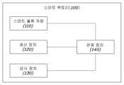
도 1을 참조하면, 스마트 팩토리(100)는 스마트 물류 차량(110), 생산 장치(120), 감시 장치(130) 및 관제 장치(140)를 포함할 수 있다.Referring to FIG. 1, a smart factory (100) may include a smart logistics vehicle (110), a production device (120), a monitoring device (130), and a control device (140).
스마트 팩토리(100)는 생산물의 생산 공정과 목표 생산 속도에 따라 복수의 스마트 물류 차량(110), 복수의 생산 장치(120) 및 복수의 감지 장치(130)가 구비될 수 있다. 이하, 각 구성 요소를 설명한다.A smart factory (100) may be equipped with multiple smart logistics vehicles (110), multiple production devices (120), and multiple detection devices (130) depending on the production process and target production speed of the product. Each component is described below.
먼저, 스마트 물류 차량(110)은 자율 주행 모바일 로봇(Autonomous Mobile Robot, 이하, 편의상 'AMR'이라 칭함)과 무인 반송차(Automated Guided Vehicle, 이하, 편의상 'AGV'라 칭함)를 포함할 수 있다. 스마트 팩토리(100)에서 스마트 물류 차량(110)의 운용 방침에 따라 AGV나 AMR 중 한 종류만 운용할 수도 있고, 단일 스마트 팩토리(100) 내에서 AGV와 AMR이 함께 운용될 수도 있다.First, the smart logistics vehicle (110) may include an autonomous mobile robot (hereinafter, referred to as 'AMR' for convenience) and an automated guided vehicle (hereinafter, referred to as 'AGV' for convenience). Depending on the operation policy of the smart logistics vehicle (110) in the smart factory (100), only one type of AGV or AMR may be operated, or AGV and AMR may be operated together within a single smart factory (100).
AGV는 일반적으로 AGV의 안내(guide)를 위해 바닥에 배치된 안내 설비를 인식 및 추종함으로써 스마트 팩토리(100) 내에서 요구되는 동작(이동, 방향 전환, 정지 등)을 수행하게 된다. 여기서 안내 설비란 광학적으로 인식 가능한 마커(스폿, 2D 코드 등), 근거리에서 비접촉식으로 인식 가능한 태그(예컨대, NFC 태그, RFID 태그 등), 마그네틱 스트립, 와이어 등을 의미할 수 있으나, 이는 예시적인 것으로 반드시 이에 한정되는 것은 아니다. 안내 설비는 바닥에 연속적으로 배치될 수도 있고, 불연속적으로 상호 이격되어 배치될 수도 있다. AGV는 기본적으로 안내 설비의 인식과 추종을 통해 동작을 수행하기 때문에 운용 전에 안내 설비가 미리 설치되어 있을 것을 요구하여, 새로운 경로로 AGV를 이동시키거나 기존 경로를 수정해야 할 경우, 안내 설비의 신설이나 수정이 물리적으로 이루어질 필요가 있다. 또한, AGV는 안내 설비를 통해 설정된 경로를 벗어나지 않으므로 경로 상 또는 주변에 장애물이 감지된 경우 감지된 장애물이 사라지거나 별도의 제어를 받을 때까지 정지하는 것이 일반적이다. AGV의 운용에 있어서 관제 장치(140)는 안내 설비를 기준으로 AGV를 제어해야 하므로, 현재 위치에서 '3번째 마커가 인식될 때까지 주행', '3번째 마커가 인식되면 헤딩 방향을 90도 전환' 등과 같은 의미의 명령을 개별 명령 단위 또는 복수의 명령을 포함하는 미션(예컨대, 회수, 공급, 충전, 패트롤 등) 단위로 AGV에 전달할 수 있다.AGVs generally perform required actions (movement, direction change, stop, etc.) within a smart factory (100) by recognizing and following guide devices placed on the floor for guiding the AGV. Here, the guide devices may refer to optically recognizable markers (spots, 2D codes, etc.), tags that can be recognized in a close range without contact (e.g., NFC tags, RFID tags, etc.), magnetic strips, wires, etc., but this is only an example and is not necessarily limited thereto. The guide devices may be placed continuously on the floor or may be placed discontinuously and spaced apart from each other. Since AGVs basically perform actions by recognizing and following guide devices, they require that guide devices be installed in advance before operation. Therefore, when moving the AGV to a new path or modifying an existing path, the installation or modification of guide devices must be physically performed. In addition, since AGVs do not deviate from the path set by the guide devices, when an obstacle is detected on or around the path, it is common for them to stop until the detected obstacle disappears or until separate control is received. In the operation of the AGV, the control device (140) must control the AGV based on the guidance equipment, so commands such as 'drive until the third marker is recognized' from the current location, 'change the heading direction by 90 degrees when the third marker is recognized', etc. can be transmitted to the AGV as individual command units or mission units (e.g., recovery, supply, charging, patrol, etc.) including multiple commands.
AMR은 주변 감지를 통해 현재 위치를 판단(즉, 측위)할 수 있으며, 측위와 맵을 이용하여 자체 경로 설정(path planning)이 가능한 점이 AGV와 가장 구분되는 점이라 할 수 있다. 따라서, AMR과 관제 장치(140)에 좌표가 호환되는 맵이 공유된 경우 관제 장치(140)가 AMR에 좌표 기반으로 경로를 지시하는 방식으로 AMR을 제어할 수 있게 된다. 또한, 주행 중 장애물이 감지된 경우 AMR은 자체적으로 회피 경로를 설정하여 장애물을 회피한 후 기존 경로로 복귀할 수 있다. 관제 장치(140)가 AMR의 경로를 하나 이상의 경유 좌표로 설정하는 기능을 글로벌 패스 플래닝(global path planning)이라 칭할 수 있으며, 글로벌 패스 플래닝에 따른 경유 좌표 사이에서 AMR이 이동 경로를 설정하거나 회피 경로를 설정하는 기능을 로컬 패스 플래닝(local path planning)이라 칭할 수 있다.AMR can determine its current location (i.e., positioning) by sensing its surroundings, and its ability to perform path planning on its own using positioning and a map is the most distinguishing feature from AGV. Accordingly, if a map with compatible coordinates is shared between the AMR and the control device (140), the control device (140) can control the AMR by instructing the AMR on a path based on the coordinates. In addition, if an obstacle is detected during driving, the AMR can set an avoidance path on its own, avoid the obstacle, and then return to the original path. The function of the control device (140) setting the path of the AMR to one or more transit coordinates can be referred to as global path planning, and the function of the AMR setting a movement path or an avoidance path between transit coordinates according to the global path planning can be referred to as local path planning.
보다 상세한 스마트 물류 차량(110)의 구성은 도 3 및 도 4를 참조하여, AMR의 주행 제어 과정은 도 5를 참조하여 각각 후술하기로 한다.A more detailed configuration of a smart logistics vehicle (110) will be described later with reference to FIGS. 3 and 4, and the driving control process of the AMR will be described later with reference to FIG. 5.
다음으로, 생산 장치(120)는 스마트 팩토리(100)에서 생산물의 생산 공정을 수행하는 장치(예컨대, 로봇암, 컨베이어 벨트 등)를 의미할 수 있으며, 보다 넓은 의미에서 생산 공정이 사람에 의해 수행될 경우 스마트 물류 차량(110)의 출입 등의 미션 수행을 보조하기 위해 배치된 장치를 의미할 수도 있다. 미션 수행을 보조하기 위해 배치된 장치라 함은, 특정 생산 공정이 수행되는 영역 내에서 스마트 물류 차량(110)이 운반하는 팔레트를 내려놓거나 수거할 수 있는 지정 위치의 상태를 감지하는 장치, 공정 진행도를 판단하는 장치, 영역 내 출입 차단 수단 등이 될 수 있으나, 반드시 이에 한정되는 것은 아니다.Next, the production device (120) may refer to a device (e.g., a robot arm, a conveyor belt, etc.) that performs a production process of a product in a smart factory (100), and in a broader sense, may refer to a device positioned to assist in the performance of a mission, such as entry and exit of a smart logistics vehicle (110), when the production process is performed by a person. A device positioned to assist in the performance of a mission may refer to a device that detects the status of a designated location where a pallet carried by a smart logistics vehicle (110) can be put down or collected within an area where a specific production process is performed, a device that determines the progress of the process, a means for blocking entry and exit within an area, etc., but is not necessarily limited thereto.
예를 들어, 생산 장치(120)는 PLC(Programmable Logic Controller)를 통해 제어되며, 공정 진행과 관련하여 관제 장치(140)와 통신을 수행할 수 있다.For example, the production device (120) is controlled through a PLC (Programmable Logic Controller) and can communicate with a control device (140) in relation to the process progress.
감시 장치(130)는 스마트 팩토리(100) 내의 상황을 판단하기 위한 정보를 획득하여 관제 장치(140)로 전달하는 기능을 수행할 수 있다. 예컨대, 감시 장치(130)는 카메라, 근접 센서 등을 포함할 수 있으나, 반드시 이에 한정되는 것은 아니다.The monitoring device (130) can perform a function of obtaining information for judging the situation within the smart factory (100) and transmitting it to the control device (140). For example, the monitoring device (130) can include a camera, a proximity sensor, etc., but is not necessarily limited thereto.
관제 장치(140)는 전술한 구성 요소(110, 120, 130)와 통신을 수행하여 스마트 팩토리(100)의 운용에 필요한 정보를 획득하거나 각 구성 요소를 제어할 수 있다. 예컨대, 관제 장치(140)는 스마트 물류 차량(110)의 배차, 경로 설정, 미션 할당, 생산물별 공정 관리, 자재 관리 등을 수행할 수 있다.The control device (140) can perform communication with the aforementioned components (110, 120, 130) to obtain information necessary for the operation of the smart factory (100) or control each component. For example, the control device (140) can perform dispatching of smart logistics vehicles (110), route setting, mission assignment, process management by product, material management, etc.
구현에 있어서, 관제 장치(140)는 AGV/AMR의 위치를 기반으로 주변 공정 설비를 제어하고, AGV/AMR의 미션 기반 제어를 수행하는 로컬 관제 장치(ACS: AMR/AGV Control System)와, 둘 이상의 로컬 관제 장치를 통합하여 관제하는 통합 관제 장치(MoRIMS: Mobile Robot Integrated Monitoring System)를 포함할 수 있다. 통합 관제 장치는 복수의 로컬 관제 장치 각각으로부터 스마트 팩토리(100) 내의 전 스마트 물류 로봇(110)의 상태와 경로, 물류 흐름설정 및 트래픽 제어를 수행할 수 있다. 예컨대, 로컬 관제 장치(ACS)가 동일 제조사나 동일 기종의 스마트 물류 로봇 단위로 구비될 경우, 통합 관제 장치는 복수의 로컬 관제 장치(ACS)를 통해 획득되는 정보를 기반으로 이기종간 트래픽 분산 제어를 통해 교차/중첩 구역의 병목 수준 분석, 주행 가/감속 제어, 회피 경로 재생성 등 충돌 방지를 위한 통합 제어를 수행할 수 있다.In implementation, the control device (140) may include a local control device (ACS: AMR/AGV Control System) that controls surrounding process facilities based on the location of the AGV/AMR and performs mission-based control of the AGV/AMR, and an integrated control device (MoRIMS: Mobile Robot Integrated Monitoring System) that integrates and controls two or more local control devices. The integrated control device may perform status and path, logistics flow setting, and traffic control of all smart logistics robots (110) in the smart factory (100) from each of the plurality of local control devices. For example, when the local control device (ACS) is equipped as a unit of smart logistics robots of the same manufacturer or the same model, the integrated control device may perform integrated control for collision prevention, such as bottleneck level analysis of an intersection/overlapping area, driving acceleration/deceleration control, and avoidance path regeneration, through traffic distribution control between heterogeneous types based on information acquired through the plurality of local control devices (ACS).
아울러, 통합 관제 장치도 그 상위 제어 주체로 제조 실행 시스템(MES: Manufacturing Execution System)을 가질 수 있으며, 제조 실행 시스템(MES)은 다시 자동화 스케쥴러(APS: Advanced Planning & Scheduling)와 연동될 수 있다.In addition, the integrated control device can have a manufacturing execution system (MES) as its upper control subject, and the manufacturing execution system (MES) can be linked with an automated scheduler (APS: Advanced Planning & Scheduling).
전술한 스마트 팩토리(100)의 구성(110, 120, 130, 140) 외에, 비컨, 중계기, AP(Access Point) 등과 같은 각 구성요소간의 상호 통신을 위한 장치, 스마트 물류 차량(110)의 충전을 위한 충전기, 부품 저장이나 적재를 위한 적재 공간, 완제품이나 중간 생산물이 보관되는 공간, 신호등, 차단기, 유휴 스마트 물류 차량(110)의 대기 공간 등이 스마트 팩토리(100) 내에 적절히 배치될 수 있음은 물론이다.In addition to the configuration (110, 120, 130, 140) of the smart factory (100) described above, devices for mutual communication between each component, such as beacons, repeaters, and APs (Access Points), chargers for charging smart logistics vehicles (110), loading spaces for storing or loading parts, spaces for storing finished products or intermediate products, traffic lights, circuit breakers, and waiting spaces for idle smart logistics vehicles (110), can of course be appropriately placed within the smart factory (100).
이하에서는 도 2를 참조하여 본 발명의 실시예들에 적용될 수 있는 관제 장치(140)의 구성을 설명한다.Below, the configuration of a control device (140) that can be applied to embodiments of the present invention is described with reference to FIG. 2.
도 2는 본 발명의 실시예들에 적용될 수 있는 관제 장치 구성의 일례를 나타내는 블럭도이다. 도 2에 도시된 각 구성 요소는 본 발명의 실시예들과 관련된 구성 요소를 위주로 나타낸 것으로, 실제 관제 장치(140)의 구현에 있어서는 이보다 많거나 적은 구성 요소가 포함될 수도 있다.FIG. 2 is a block diagram showing an example of a control device configuration that can be applied to embodiments of the present invention. Each component illustrated in FIG. 2 mainly shows components related to embodiments of the present invention, and in the implementation of an actual control device (140), more or fewer components may be included.
도 2를 참조하면, 관제 장치(140)는 펌웨어 관리부(141), 트래픽 제어부(142), 공정 관리부(143), 생산/물류 관리부(144), 재고 관리부(145), 통신부(146), 차량 모니터링부(147), 맵 관리부(148)를 포함할 수 있다.Referring to FIG. 2, the control device (140) may include a firmware management unit (141), a traffic control unit (142), a process management unit (143), a production/logistics management unit (144), an inventory management unit (145), a communication unit (146), a vehicle monitoring unit (147), and a map management unit (148).
펌웨어 관리부(141)는 통신부(146)를 통해 스마트 물류 차량(110)의 최신 펌웨어를 획득하고, 스마트 물류 차량(110)에 전송하여 펌웨어 업데이트가 수행되도록 하여 스마트 풀류 차량(110)의 펌웨어를 최신 상태로 유지할 수 있다.The firmware management unit (141) obtains the latest firmware of the smart logistics vehicle (110) through the communication unit (146) and transmits it to the smart logistics vehicle (110) to perform a firmware update, thereby maintaining the firmware of the smart full-flow vehicle (110) up to date.
트래픽 제어부(142)는 스마트 물류 차량(110)의 경로를 기반으로 신호등과 차단기를 제어하며, 트래픽에 따라 스마트 물류 차량(110)의 경로를 재산정할 수도 있다.The traffic control unit (142) controls traffic lights and barriers based on the route of the smart logistics vehicle (110), and can also re-evaluate the route of the smart logistics vehicle (110) depending on traffic.
공정 관리부(143)는 생산물별 공정을 정의하고, 공정 진척도, 진행 위치 등의 미션을 관리할 수 있다.The process management department (143) can define processes for each product and manage missions such as process progress and progress location.
생산/물류 관리부(144)는 미션 기반으로 스마트 물류 차량(110)을 배차할 수 있다.The production/logistics management department (144) can dispatch smart logistics vehicles (110) based on missions.
재고 관리부(145)는 자재별 위치와 수량을 관리하며, 이러한 정보는 스마트 물류 차량(110)을 팔레트 픽업이나 회수를 위해 실제 자재의 조립/소모가 감지되는 시점보다 미리 목적지로 출발시키는 등 보다 효율적인 공정 운용을 위해 유용할 수 있다.The inventory management department (145) manages the location and quantity of each material, and this information can be useful for more efficient process operation, such as sending a smart logistics vehicle (110) to the destination earlier than the time when actual assembly/consumption of materials is detected for pallet pickup or retrieval.
통신부(146)는 스마트 물류 차량(110), 생산 장치(120) 및 감시 장치(130)와 같은 스마트 팩토리(100)의 내부 구성 요소는 물론, 펌웨어 업데이트 서버 등과 같은 외부 개체와의 통신도 수행할 수 있다.The communication unit (146) can perform communication with internal components of the smart factory (100), such as a smart logistics vehicle (110), a production device (120), and a monitoring device (130), as well as external entities, such as a firmware update server.
차량 모니터링부(147)는 개별 스마트 물류 차량(110)의 위치, 경로, 배터리 상태, 통신 상태, 파워 트레인 상태 등을 모니터링할 수 있다. 여기서, 경로는 웨이포인트 기반의 글로벌 경로와 실시간 로컬 경로를 포함하는 개념이다. 또한, 배터리 상태는 전압, 전류, 온도, 전압과 전류의 피크치, 충전 상태(SOC: State Of Charge), 내구 상태(SOH: State Of Health) 등을 포함할 수 있다. 통신 상태는 현재 활성화된 통신 프로토콜(Wi-Fi 등), 연결된 AP, AP와의 거리, 사용 중인 채널 등에 대한 정보를 포함할 수 있다. 아울러, 파워 트레인 상태는 구동계의 부하, 온도, RPM 등을 포함할 수 있다.The vehicle monitoring unit (147) can monitor the location, route, battery status, communication status, power train status, etc. of individual smart logistics vehicles (110). Here, the route is a concept including a global route based on waypoints and a real-time local route. In addition, the battery status can include voltage, current, temperature, peak voltage and current, state of charge (SOC: State Of Charge), state of endurance (SOH: State Of Health), etc. The communication status can include information about the currently activated communication protocol (such as Wi-Fi), connected AP, distance to AP, channel in use, etc. In addition, the power train status can include load, temperature, RPM, etc. of the drivetrain.
그 외에도 차량 모니터링부(147)는 개별 스마트 물류 차량(110)에 현재 할당된 미션, 동작 모드, 펌웨어 버전 등을 확인할 수도 있다.In addition, the vehicle monitoring unit (147) can also check the mission, operation mode, firmware version, etc. currently assigned to each smart logistics vehicle (110).
맵 관리부(148)는 스마트 물류 차량(110) 중 AMR이 스마트 팩토리(100) 내부를 주행하면서 획득한 그리드 맵 형태의 맵 데이터를 획득하며, 획득된 맵 데이터를 팩토리 관리자가 편집할 수 있는 툴을 제공할 수 있다. 맵 데이터의 편집을 통해, 스마트 물류 차량(110)이 진입시 미리 설정된 하나 이상의 동작을 수행하는 영역(zone), 가상 차선(lane), 교차로, 진입 금지 영역 등이 설정될 수 있으나, 이는 예시적인 것으로 반드시 이에 한정되는 것은 아니다. 또한, 맵 관리부(148)는 최초 그리드 맵을 실제 주행을 통해 획득한 스마트 물류 차량(110) 이외의 나머지 스마트 물류 차량(110)에 해당 맵을 통신부(146)를 통해 배포할 수도 있다.The map management unit (148) may obtain map data in the form of a grid map obtained when an AMR among smart logistics vehicles (110) drives inside a smart factory (100), and may provide a tool for a factory manager to edit the obtained map data. By editing the map data, a zone, a virtual lane, an intersection, a no-entry zone, etc., in which one or more preset actions are performed when a smart logistics vehicle (110) enters, may be set, but this is only an example and is not necessarily limited thereto. In addition, the map management unit (148) may distribute the corresponding map to the remaining smart logistics vehicles (110) other than the smart logistics vehicle (110) that obtained the initial grid map through actual driving, through the communication unit (146).
다음으로, 도 3 및 도 4를 참조하여 스마트 물류 차량을 설명한다.Next, a smart logistics vehicle is described with reference to FIGS. 3 and 4.
도 3은 본 발명의 실시예들에 적용될 수 있는 스마트 물류 차량 구성의 일례를 나타내는 블럭도이다.FIG. 3 is a block diagram showing an example of a smart logistics vehicle configuration that can be applied to embodiments of the present invention.
도 3을 참조하면, 스마트 물류 차량(110)은 주행부(111), 센싱부(112), 적재부(113), 통신부(114) 및 제어부(115)를 포함할 수 있다. 이하, 각 구성 요소를 설명한다.Referring to FIG. 3, a smart logistics vehicle (110) may include a driving unit (111), a sensing unit (112), a loading unit (113), a communication unit (114), and a control unit (115). Hereinafter, each component will be described.
주행부(111)는 스마트 물류 차량(110)의 이동, 조향 및 정지에 관여하는 구동원, 휠 및 서스펜션 등을 포함할 수 있다. 구동원은 내장된 배터리(미도시)로부터 전력을 공급받는 전기 모터가 이용될 수 있다. 휠은 구동원으로부터 구동력을 공급받는 하나 이상의 구동륜과, 구동력을 공급받지 않고 차체의 이동에 의해 회전하는 비구동륜을 포함할 수 있다. 구현에 따라, 복수의 구동륜이 구비된 경우 구동륜별로 구동원이 매칭되어 각 구동륜의 회전이 독립적으로 제어될 수 있다. 이러한 경우, 서로 다른 구동륜의 회전 방향을 상이하게 함으로써 별도의 조향 수단 없이도 차체를 회전시켜 조향이 이루어지도록 할 수 있다. 적어도 일부의 비구동륜은 캐스터 타입 휠로 구성될 수 있으나, 이는 예시적인 것으로 반드시 이에 한정되는 것은 아니다.The driving unit (111) may include a driving source, wheels, suspension, etc. involved in the movement, steering, and stopping of the smart logistics vehicle (110). The driving source may be an electric motor that receives power from a built-in battery (not shown). The wheels may include one or more driving wheels that receive driving force from the driving source, and non-driving wheels that rotate by the movement of the vehicle body without receiving the driving force. According to the implementation, when a plurality of driving wheels are provided, the driving source may be matched to each driving wheel so that the rotation of each driving wheel may be independently controlled. In this case, by making the rotation directions of different driving wheels different, the vehicle body may be rotated without a separate steering means so that steering may be performed. At least some of the non-driving wheels may be configured as caster type wheels, but this is exemplary and is not necessarily limited thereto.
센싱부(112)는 스마트 물류 차량(110) 주변 환경이나 자체 동작 상태 등을 감지하기 위한 것으로, 2D 레이저 스캐너(예컨대, LiDAR), 3D 비전(스테레오) 카메라, 다축 자이로 센서, 가속도 센서, 휠 인코더, 근접 센서 중 적어도 하나를 포함할 수 있다.The sensing unit (112) is intended to detect the surrounding environment of the smart logistics vehicle (110) or its own operating status, and may include at least one of a 2D laser scanner (e.g., LiDAR), a 3D vision (stereo) camera, a multi-axis gyro sensor, an acceleration sensor, a wheel encoder, and a proximity sensor.
인코더는 발광소자(예컨대, 광 다이오드)에서 출사되는 광을 이용하여 휠이 얼마나 회전했는지 판단할 수 있는 정보를 출력할 수 있다. 예컨대, 인코더는 단위 시간동안 휠 또는 휠과 함께 회전하는 디스크에 원주 방향을 따라 배치된 슬릿의 수를 카운팅할 수 있다. 제어부(115)는 인코더와 자이로 센서를 통해 획득된 데이터로 시간 대비 위치 변화량을 분석하여 변위를 추정하는 오도메트리(odometry) 수행이 가능하다. 다만, 휠의 슬립이나 마모(휠 동반경 변화)로 인해 인코더 데이터를 기반으로 추정된 변위가 실제 변위와 오차가 있을 수 있다. 따라서, 오도메트리 수행시 제어부(115)는 휠과 자이로 센서로부터 수집된 정보를 소정 알고리즘(예컨대, EKF: Extended Kalman Filter)으로 노이즈 및 오차에 대한 보정을 수행하여 실제 값에 가까운 경향성이 있는 결과를 출력할 수 있다. 이러한 오도메트리는 후술할 2D 레이저 스캐너를 이용한 현재 위치 판단(Localization)이 불가할 경우 특히 유용할 수 있다.The encoder can output information that can determine how much the wheel has rotated by using light emitted from a light-emitting element (e.g., a photodiode). For example, the encoder can count the number of slits arranged along the circumference of the wheel or a disk rotating with the wheel per unit time. The control unit (115) can perform odometry to estimate displacement by analyzing the amount of position change with respect to time using data acquired through the encoder and the gyro sensor. However, the displacement estimated based on the encoder data may have an error from the actual displacement due to wheel slip or wear (wheel-related diameter change). Therefore, when performing odometry, the control unit (115) can perform noise and error correction on the information collected from the wheel and the gyro sensor using a predetermined algorithm (e.g., EKF: Extended Kalman Filter) to output a result that tends to be close to the actual value. This odometry can be particularly useful when localization using a 2D laser scanner, described later, is not possible.
2D 레이저 스캐너는 회전하는 반사경을 통해 주변에 레이저를 조사하고, 반사되어 돌아오는 신호를 감지함으로써 주변 환경을 스캔할 수 있다. 이때, 반사된 신호의 강도와 조사/수신 간의 시간 차이를 분석하여 포인트 클라우드 형상의 감지 결과를 출력할 수 있다.A 2D laser scanner can scan the surrounding environment by projecting a laser beam onto the surrounding area through a rotating reflector and detecting the reflected signal. At this time, the intensity of the reflected signal and the time difference between the irradiation and reception can be analyzed to output the detection result in the form of a point cloud.
3D 비전 카메라는 일정 거리만큼 이격된 두 개의 카메라 간의 시차, 즉, 각 카메라를 통해 촬영된 이미지 사이의 픽셀 거리를 기반으로 물체까지의 거리를 계산할 수 있다. 이때, 동일 색상의 평면체(예컨대, 흰 벽) 등에 대해서도 감지가 가능하도록 소정 패턴의 적외선 광을 투사하는 텍스쳐 프로젝터(texture projector)가 구비될 수도 있다.The 3D vision camera can calculate the distance to an object based on the parallax between two cameras spaced apart by a certain distance, that is, the pixel distance between the images captured by each camera. At this time, a texture projector that projects infrared light of a certain pattern can also be provided so that detection is possible even for flat objects of the same color (e.g., a white wall).
일반적으로 2D 레이저 스캐너는 맵핑, 네비게이션, 사물 인식 등에 사용되고, 3D 카메라는 네비게이션 중 특히 장애물 회피를 위해 활용될 수 있으나, 이는 예시적인 것으로 반드시 이에 한정되는 것은 아니다.Typically, 2D laser scanners are used for mapping, navigation, object recognition, etc., and 3D cameras can be used for navigation, especially for obstacle avoidance, but these are examples and are not necessarily limited thereto.
적재부(113)는 이송 대상 물품을 적재하기 위한 수단으로, 차체 상부의 상판 자체 또는 상판에 배치된 테이블, 리프트, 수직 축을 따라 회전하는 턴테이블, 포크 리프트, 컨베이어 또는 이들을 조합한 형태가 될 수 있다. 포크 리프트의 경우 지게차와 유사하게, 텔레스코픽 및 틸팅 기능을 지원할 수도 있다.The loading unit (113) is a means for loading the transported goods, and may be a top plate on the upper part of the vehicle body itself, a table placed on the top plate, a lift, a turntable rotating along a vertical axis, a forklift, a conveyor, or a combination thereof. In the case of a forklift, similar to a forklift, it may also support telescopic and tilting functions.
통신부(114)는 생산 장치(120), 관제 장치(140) 등 스마트 팩토리(100) 내의 타 구성 요소와 통신을 수행할 수 있으며, 스마트 물류 차량(110)간의 통신도 지원할 수 있으며, 충전 미션 수행시 충전기와의 통신도 가능하다.The communication unit (114) can communicate with other components within the smart factory (100), such as the production device (120) and the control device (140), and can also support communication between smart logistics vehicles (110), and can also communicate with the charger when performing a charging mission.
제어부(115)는 전술한 각 구성 요소(111, 112, 113, 114)의 전반적인 제어를 수행하는 주체로서, 통신부(114)를 통해 관제 장치(140)로부터 획득된 정보를 기반으로 현재 미션, 현재 위치, 목적지 판단, 경로 플래닝, 적재부 제어 등을 수행할 수 있다.The control unit (115) is a subject that performs overall control of each of the aforementioned components (111, 112, 113, 114), and can perform current mission, current location, destination judgment, route planning, load control, etc. based on information obtained from the control device (140) through the communication unit (114).
도 4은 본 발명의 실시예들에 적용될 수 있는 스마트 물류 차량 외관의 일례를 나타내는 사시도이다.FIG. 4 is a perspective view showing an example of the exterior of a smart logistics vehicle that can be applied to embodiments of the present invention.
도 4를 참조하면, 스마트 물류 차량(110)으로 AMR의 일례가 도시된다. 차체는 전체적으로 1축 방향을 따라 연장되는 장축을 갖는 트랙형 평면 형상을 가질 수 있다. 하나의 구동륜(111-1)은 1축 방향으로 차체의 중앙부에 배치되며, 2축 방향으로 일측에 배치될 수 있으며, 다른 구동륜(미도시)은 2축 방향으로 하나의 구동륜(111-1)과 대향하도록 타측에 배치될 수 있다. 이러한 구동륜 배치를 '차동형 드라이브(DD)'라 칭할 수 있다. 도 4에 도시되지는 않았으나, 차체 하부에 둘 이상의 비구동륜이 배치될 수 있다. 이러한 경우, 두 개의 구동륜이 동일 방향으로 동일 속도로 회전하면 1축 방향을 따라 전진 또는 후진이 가능하며, 서로 반대 방향으로 동일 속도로 회전할 경우 3축 방향을 따라 연장되며 차체의 평면 중심(C)을 지나는 회전축을 기준으로 회전할 수 있다. 또한, 차체 전면부에는 센서부(112)가 배치될 수 있으며, 상면부에는 적재부(113)가 배치될 수 있다. 적재부(113)는 3축 방향을 따라 승강이 가능하도록 구성될 수 있으며, 상부면에 가이드(113-1)를 통해 랙(rack)이나 트레이(tray) 등이 고정될 수 있다.Referring to FIG. 4, an example of an AMR is illustrated as a smart logistics vehicle (110). The body may have a track-shaped planar shape having a long axis extending along a single axis direction as a whole. One driving wheel (111-1) may be arranged in the center of the body in a single-axis direction, may be arranged on one side in a two-axis direction, and another driving wheel (not shown) may be arranged on the other side to face one driving wheel (111-1) in a two-axis direction. This arrangement of the driving wheels may be referred to as a 'differential drive (DD)'. Although not illustrated in FIG. 4, two or more non-driving wheels may be arranged on the lower part of the body. In this case, if two driving wheels rotate in the same direction at the same speed, they can move forward or backward along a single-axis direction, and if they rotate in opposite directions at the same speed, they can extend along a three-axis direction and rotate based on a rotation axis passing through the plane center (C) of the body. In addition, a sensor unit (112) may be placed on the front of the body, and a loading unit (113) may be placed on the upper surface. The loading unit (113) may be configured to be able to rise and fall along three axes, and a rack or tray, etc. may be fixed to the upper surface through a guide (113-1).
다만, 상술한 도 4의 AMR 형태는 예시적인 것으로, AGV가 이와 유사한 형태를 갖거나, AMR이 이와 상이한 형태를 가질 수도 있음은 물론이다.However, the AMR shape of Fig. 4 described above is exemplary, and it is obvious that the AGV may have a similar shape or the AMR may have a different shape.
다음으로, 도 5를 참조하여 스마트 물류 차량(110)의 주행 과정을 설명한다.Next, the driving process of the smart logistics vehicle (110) will be described with reference to Fig. 5.
도 5는 본 발명의 실시예들에 적용될 수 있는 스마트 물류 차량(110)의 주행 과정의 일례를 나타내는 순서도이다. 도 5에서는 편의상 스마트 물류 차량(110)이 측위 및 로컬 경로 설정이 가능한 AMR인 것으로 가정한다.Fig. 5 is a flowchart showing an example of a driving process of a smart logistics vehicle (110) that can be applied to embodiments of the present invention. In Fig. 5, for convenience, it is assumed that the smart logistics vehicle (110) is an AMR capable of positioning and local route setting.
도 5를 참조하면, 먼저 AMR이 스마트 팩토리(100) 내부를 주행하면서 라이다 등을 통해 실측 그리드 맵을 획득할 수 있다(S501).Referring to Fig. 5, first, while the AMR drives inside a smart factory (100), a real-world grid map can be obtained through lidar, etc. (S501).
AMR은 획득한 그리드 맵을 관제 장치(140)로 전송하면, 관제 장치(140)의 맵 관리부(148)에서 그리드 맵 에디팅 및 매칭 과정이 수행될 수 있다(S502). 여기서 에디팅 과정은 전술한 그리드 맵에 전술한 각종 영역(zone)을 설정하는 과정, 그리드별로 코스트를 부여하는 과정 등을 포함할 수 있다. 여기서 코스트의 부여는 AMR이 장애물 주변이나 진입해서는 안되는 영역으로 이동하지 않도록 장애물이나 진입 금지 영역에 가까울수록 높게 코스트가 부여되는 방향으로 수행될 수 있다. 이는 AMR이 로컬 경로를 설정함에 있어서 웨이 포인트 사이에서 가장 코스트가 낮은 셀의 집합을 경로로 선택하기 때문이다.When the AMR transmits the acquired grid map to the control device (140), the grid map editing and matching process can be performed in the map management unit (148) of the control device (140) (S502). Here, the editing process can include the process of setting the aforementioned various zones in the aforementioned grid map, the process of assigning a cost to each grid, etc. Here, the assignment of the cost can be performed in a direction in which the cost is assigned higher the closer the AMR is to an obstacle or a no-entry area so that the AMR does not move around an obstacle or into an area that it should not enter. This is because the AMR selects a set of cells with the lowest cost among waypoints as the path when setting a local path.
또한, 맵 매칭 과정은 스마트 팩토리(100)의 설계에 사용된 CAD 맵, 실측 그리드 맵(라이다 맵)과 에디팅 과정을 거친 토폴로지(topolpogy)맵 간의 좌표를 일치시키는 과정을 의미할 수 있다.Additionally, the map matching process may mean a process of matching coordinates between a CAD map used in the design of a smart factory (100), a real-world grid map (lidar map), and a topology map that has gone through an editing process.
이후 관제 장치(140)는 통신부(146)를 통해 토폴로지맵을 팩토리 내의 모든 AMR에 공유할 수 있다(S503).Afterwards, the control device (140) can share the topology map with all AMRs within the factory through the communication unit (146) (S503).
이후의 단계는 개별 AMR에 적용되는 과정일 수 있다.Subsequent steps may be applied to individual AMRs.
AMR은 센싱부(112)의 센서 데이터와 획득한 맵을 통해 맵 상에서 현재 위치를 판단(localization)할 수 있다(S504). 예컨대, AMR은 라이다를 통해 획득된 주변 지형과 맵을 특징점 기반으로 비교하여 현재 위치를 판단할 수 있다.AMR can determine the current location on the map (localization) through the sensor data of the sensing unit (112) and the acquired map (S504). For example, AMR can determine the current location by comparing the surrounding terrain acquired through the lidar and the map based on feature points.
관제 장치(140)는 특정 AMR을 선택하여 미션을 부여할 수 있으며, 미션에는 일반적으로 글로벌 경로 설정(global path planning)을 통해 결정된 하나 이상의 웨이 포인트가 부여될 수 있다. 웨이 포인트는 맵 상의 좌표로 정의될 수 있으며, 해당 좌표에서 AMR이 향해야 할 방향(즉, heading)에 대한 정보가 수반될 수 있다. 이러한 미션 부여에 따라, AMR에 목적지가 설정될 수 있으며(S505의 Yes), AMR은 토폴로지 맵의 코스트를 기반으로 웨이 포인트 사이에서 로컬 경로 설정(local path planning)을 수행할 수 있다(S506).The control device (140) can select a specific AMR and assign a mission, and the mission can be assigned one or more waypoints, which are generally determined through global path planning. The waypoints can be defined as coordinates on a map, and can be accompanied by information about the direction (i.e., heading) that the AMR should face at the coordinates. Based on the assignment of the mission, a destination can be set for the AMR (Yes in S505), and the AMR can perform local path planning between waypoints based on the cost of the topology map (S506).
경로가 판단되면 AMR은 주행을 개시하며(S507), 주행 중 센싱부(112)를 통해 장애물이 감지된 경우(S508의 Yes), 감지된 장애물을 우회하기 위한 로컬 경로 탐색을 수행하여 회피 기동을 수행할 수 있다(S509). 경우에 따라, 회피 기동에 따라, 또는 회피 기동의 실패에 따라 관제 장치(140)는 해당 AMR의 미션을 갱신할 수도 있다.Once the path is determined, the AMR starts driving (S507), and if an obstacle is detected by the sensing unit (112) during driving (Yes in S508), local path search can be performed to bypass the detected obstacle and perform an evasive maneuver (S509). In some cases, depending on the evasive maneuver or the failure of the evasive maneuver, the control device (140) can update the mission of the AMR.
또한, AMR은 목적지에 도달할 때까지 주행 중 전술한 오도메트리 기법을 통해 이동 중 위치 오차를 보정할 수도 있다(S510).Additionally, the AMR can also compensate for position errors during movement using the aforementioned odometry technique until it reaches its destination (S510).
이후 목적지에 도달한 경우(S511), AMR은 미션 기반 기동을 수행할 수 있다(S512). 예컨대, AMR은 특정 공정 구역에 진입하기 위한 조건의 클리어 여부를 판단하거나, 목적지에서 비어 있는 팔레트를 회수하거나, 적재부(113)에 적재된 적재물을 드랍할 수 있다.After reaching the destination (S511), the AMR can perform mission-based maneuvers (S512). For example, the AMR can determine whether conditions for entering a specific process area are clear, retrieve an empty pallet at the destination, or drop a load loaded on the loading section (113).
본 발명의 일 실시예에서는, 스마트 팩토리(100)에 위치한 복수의 스마트 물류 차량을 복수의 그룹으로 관제함으로써 스마트 팩토리(100)의 공정 효율을 향상시키고 생산성을 증대시키는 것을 목적으로 한다.In one embodiment of the present invention, the purpose is to improve the process efficiency and increase productivity of a smart factory (100) by controlling a plurality of smart logistics vehicles located in a smart factory (100) into a plurality of groups.
이하, 도 6을 참조하여 실시예에 따른 스마트 물류 차량 관제 시스템을 설명한다.Hereinafter, a smart logistics vehicle control system according to an embodiment will be described with reference to FIG. 6.
도 6은 본 발명의 일 실시예에 따른 스마트 물류 차량 관제 시스템의 구성을 나타낸 블럭도이다.FIG. 6 is a block diagram showing the configuration of a smart logistics vehicle control system according to one embodiment of the present invention.
도 6을 참조하면, 본 발명의 일 실시예에 따른 스마트 물류 차량 관제 시스템은 복수의 스마트 물류 차량, 복수의 공정 영역에 각각 구비되어 각 공정 영역을 제어하고, 공정 정보를 수집하여 제공하는 복수의 생산 장치 및 복수의 생산 장치로부터 복수의 공정 영역 각각에 대한 공정 정보를 바탕으로 복수의 스마트 물류 차량을 관제하는 관제 장치(140)를 포함할 수 있다.Referring to FIG. 6, a smart logistics vehicle control system according to one embodiment of the present invention may include a plurality of smart logistics vehicles, a plurality of production devices each equipped in a plurality of process areas to control each process area and collect and provide process information, and a control device (140) that controls the plurality of smart logistics vehicles based on process information for each of the plurality of process areas from the plurality of production devices.
도 6에서는 설명의 편의를 위해 하나의 스마트 물류 차량(110)과 하나의 생산 장치(120)가 관제 장치(140)와 정보를 주고 받는 것으로 표현하고 있으나, 이는 복수의 스마트 물류 차량과 복수의 생산 장치에 동일하게 적용되는 것으로 이해되어야 할 것이다.In Fig. 6, for convenience of explanation, one smart logistics vehicle (110) and one production device (120) are depicted as exchanging information with a control device (140), but it should be understood that this applies equally to multiple smart logistics vehicles and multiple production devices.
관제 장치(140)는 통신부(146)와 작업 스케줄 관리부(149)를 포함할 수 있으며, 공정 정보를 입력받거나 또는 스마트 물류 차량(110)의 위치, 작업 수행 및 충전량 정보를 입력받을 수 있다.The control device (140) may include a communication unit (146) and a work schedule management unit (149), and may receive process information or information on the location, work performance, and charging amount of a smart logistics vehicle (110).
이때, 공정 정보는 공정 영역에 구비된 생산 장치(120)로부터 제공되는 공정 관련 정보일 수 있으며, 공정 영역에 감시 장치(130)가 더 구비될 경우 감시 장치(130)로부터 제공되는 공정 영역의 운영 상황 정보일 수도 있다. 다만, 이는 예시적인 것으로, 반드시 이에 한정되지 않음은 물론이다. 그리고, 스마트 물류 차량(110)의 위치, 작업 수행 및 충전량 정보는 스마트 물류 차량(110)의 통신부(114)로부터 제공되는 정보일 수 있다.At this time, the process information may be process-related information provided from a production device (120) equipped in the process area, and if a monitoring device (130) is further equipped in the process area, it may also be operation status information of the process area provided from the monitoring device (130). However, this is an example, and it is not necessarily limited thereto. In addition, the location, work performance, and charging amount information of the smart logistics vehicle (110) may be information provided from the communication unit (114) of the smart logistics vehicle (110).
관제 장치(140)는 입력 정보를 기반으로 작업 정보를 생성하고, 스마트 물류 차량(110)에 전달하여 작업 정보를 기반으로 스마트 물류 차량(110)을 관제할 수 있다.The control device (140) can generate work information based on input information and transmit it to a smart logistics vehicle (110) to control the smart logistics vehicle (110) based on the work information.
이하에서는 관제 장치(140)의 구체적인 기능에 대해 설명하기로 한다.Below, the specific functions of the control device (140) will be described.
먼저, 통신부(146)는 생산 장치(120)와 연결되는 적어도 하나의 공정 제어기와 통신을 수행할 수 있다. 여기서 공정 제어기(미도시)는, 예컨대 전술한 PLC로 구현될 수 있다.First, the communication unit (146) can communicate with at least one process controller connected to the production device (120). Here, the process controller (not shown) can be implemented as, for example, the PLC described above.
통신부(146)는 생산 장치(120)로부터 공정 영역에서 수행되는 공정 정보를 지속적으로 제공받을 수 있고, 이를 작업 스케줄 관리부(149)에 전달하여 작업 스케줄 관리부(149)가 스마트 물류 차량(110)을 관제하도록 할 수 있다.The communication unit (146) can continuously receive process information performed in the process area from the production device (120) and transmit it to the work schedule management unit (149) so that the work schedule management unit (149) can control the smart logistics vehicle (110).
또한, 통신부(146)는 스마트 물류 차량(110)의 통신부(114)와도 통신을 수행할 수 있으며, 이를 통해 스마트 물류 차량(110)의 위치, 스마트 물류 차량(110)의 작업 수행 여부 및 현재 충전량(SOC : State Of Charge) 정보를 확인할 수 있으며, 작업 스케줄 관리부(149)에 해당 정보를 전달하여 스마트 물류 차량(110)을 관제하도록 할 수 있다.In addition, the communication unit (146) can also perform communication with the communication unit (114) of the smart logistics vehicle (110), through which the location of the smart logistics vehicle (110), whether the smart logistics vehicle (110) is performing work, and the current charge amount (SOC: State Of Charge) information can be checked, and the corresponding information can be transmitted to the work schedule management unit (149) to control the smart logistics vehicle (110).
한편, 작업 스케줄 관리부(149)는 통신부(146)를 통해 정보를 제공받고, 입력받은 정보를 기반으로 스마트 물류 차량(110)의 작업 정보를 생성할 수 있다. 구체적으로, 작업 스케줄 관리부(149)는 복수의 스마트 물류 차량을 복수의 그룹으로 관리할 수 있다. 여기서 복수의 그룹은 패트롤 경로를 따라 선회 작업을 수행하는 패트롤 그룹, 복수의 공정 영역 각각에서 물류 작업을 수행하는 작업 그룹 및 스마트 물류 차량(110)의 충전량이 부족하면 충전 작업을 수행하는 충전 그룹으로 구성될 수 있다. 이때, 물류 작업을 수행하는 작업 그룹은 복수의 작업 그룹으로 나누어질 수 있다. 예컨대, 공정 영역에서 공정을 마친 물류를 다음 공정 영역으로 전달하는 물류 이송 작업을 수행하는 작업 그룹과, 물류 이송 작업을 수행하기 위해 공정 영역에 미리 이동하여 대기하는 물류 대기 작업을 수행하는 작업 그룹으로 나누어질 수 있다. 또한, 복수의 그룹 구성시 각 그룹에 포함되는 스마트 물류 차량의 대수 또는 경로는 다양하게 설정될 수 있고, 각 그룹 내에서 둘 이상의 작은 그룹으로 다시 구성될 수도 있다. 다만, 이는 예시적인 것으로, 반드시 이에 한정되지 않음은 물론이다.Meanwhile, the work schedule management unit (149) can receive information through the communication unit (146) and generate work information of the smart logistics vehicle (110) based on the input information. Specifically, the work schedule management unit (149) can manage multiple smart logistics vehicles into multiple groups. Here, the multiple groups can be composed of a patrol group that performs a turning operation along a patrol route, a work group that performs a logistics operation in each of multiple process areas, and a charging group that performs a charging operation when the charge of the smart logistics vehicle (110) is insufficient. At this time, the work group that performs the logistics operation can be divided into multiple work groups. For example, it can be divided into a work group that performs a logistics transfer operation that transfers logistics that have completed a process in a process area to the next process area, and a work group that performs a logistics waiting operation that moves to the process area in advance and waits to perform the logistics transfer operation. In addition, when multiple groups are composed, the number or routes of smart logistics vehicles included in each group can be set in various ways, and each group can be re-composed into two or more smaller groups. However, this is an example, and it should be understood that the present invention is not necessarily limited thereto.
아울러, 작업 스케줄 관리부(149)에서 관리되는 복수의 그룹 각각에는 우선순위가 사전에 설정될 수 있으며, 복수의 그룹 각각에 대한 우선순위는 외부 신호(예컨대, 관제 장치(140)를 관리하는 관리자의 수동 조작)에 의해 설정될 수 있다. 작업 스케줄 관리부(149)는 설정된 우선순위에 따라 복수의 스마트 물류 차량의 작업이 수행되도록 관제할 수 있다. 스마트 물류 차량(110)에는 복수개의 작업 명령이 입력될 수 있고, 작업 스케줄 관리부(149)는 입력된 복수개의 작업 명령에 대응되는 작업 그룹의 우선순위를 판단하여 해당 스마트 물류 차량(110)이 우선순위가 높은 작업을 먼저 수행하도록 관제할 수 있다. 예를 들어, 물류 이송 작업을 수행하는 작업 그룹이 1순위, 선회 작업을 수행하는 패트롤 그룹이 2순위 및 충전 작업을 수행하는 충전 그룹이 3순위로 우선순위가 각각 정해지고, 스마트 물류 차량(110)에 물류 이송 작업과 선회 작업이 동시에 입력된 경우 작업 스케줄 관리부(149)는 물류 이송 작업의 우선순위와 선회 작업의 우선순위를 비교하여 더 높은 우선순위를 가진 물류 이송 작업이 먼저 수행되도록 관제할 수 있다. 다만, 이는 예시적인 것으로, 복수의 그룹 각각에 대한 우선순위는 스마트 팩토리(100)의 공정 및 운영 상황에 따라 다양하게 형성될 수 있음은 물론이다.In addition, priorities may be set in advance for each of the plurality of groups managed by the work schedule management unit (149), and the priorities for each of the plurality of groups may be set by an external signal (e.g., manual operation of a manager managing the control device (140)). The work schedule management unit (149) may control the work of a plurality of smart logistics vehicles to be performed according to the set priorities. A plurality of work commands may be input to the smart logistics vehicle (110), and the work schedule management unit (149) may determine the priorities of the work groups corresponding to the plurality of input work commands and control the corresponding smart logistics vehicle (110) to perform a task with a higher priority first. For example, if a work group performing a logistics transport task is given the 1st priority, a patrol group performing a turning task is given the 2nd priority, and a charging group performing a charging task is given the 3rd priority, and if the logistics transport task and the turning task are inputted simultaneously to a smart logistics vehicle (110), the work schedule management unit (149) can compare the priority of the logistics transport task and the priority of the turning task and control the logistics transport task with a higher priority to be performed first. However, this is merely exemplary, and it goes without saying that the priority for each of the multiple groups can be formed in various ways depending on the process and operating situation of the smart factory (100).
이하에서는 도 7을 참조하여 작업 그룹에 대해 간략하게 설명하고자 한다.Below, we will briefly describe the working group with reference to Fig. 7.
도 7은 본 발명의 일 실시예에 따른 스마트 물류 차량 관제 시스템을 도식화한 도면이다.FIG. 7 is a diagram schematically illustrating a smart logistics vehicle control system according to one embodiment of the present invention.
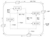
도 7을 참조하면, 복수의 스마트 물류 차량 중 작업을 수행하지 않는 스마트 물류 차량은 패트롤 경로를 따라 선회 작업을 수행할 수 있다. 도 7에서는 패트롤 경로가 복수의 공정 영역을 감싸면서 형성되어 있으나, 이는 예시적인 것으로, 패트롤 경로는 다양하게 형성될 수 있으며 이에 대한 설명은 후술하기로 한다. 또한, 설명의 편의를 위해 복수의 공정 영역이 제1 공정을 수행하는 공정 영역(이하, 제1 공정 영역이라 한다.)과 제2 공정을 수행하는 공정 영역(이하, 제2 공정 영역이라 한다.)으로 구성된 것을 가정하기로 한다.Referring to FIG. 7, a smart logistics vehicle among a plurality of smart logistics vehicles that is not performing a task can perform a turning task along a patrol path. In FIG. 7, the patrol path is formed by surrounding a plurality of process areas, but this is exemplary, and the patrol path can be formed in various ways, which will be described later. In addition, for convenience of explanation, it is assumed that the plurality of process areas are composed of a process area performing a first process (hereinafter referred to as a first process area) and a process area performing a second process (hereinafter referred to as a second process area).
제1 공정 영역에서 스마트 물류 차량(110)을 필요로 하는 경우, 선회 작업을 수행 중인 스마트 물류 차량 중 적어도 하나의 스마트 물류 차량이 제1 공정 영역으로 이동할 수 있다. 제1 공정 영역으로 이동한 스마트 물류 차량(110)은 제2 공정 영역까지 물류를 이송하는 물류 이송 작업을 수행할 수 있다. 그러나, 제1 공정 영역에서 현재 스마트 물류 차량(110)을 곧바로 필요로 하는 것은 아니지만, 미리 스마트 물류 차량(110)을 확보해두기 위해 스마트 물류 차량(110)을 필요로 하는 경우에는 선회 작업을 수행 중인 스마트 물류 차량 중 적어도 하나의 스마트 물류 차량이 제1 공정 영역 인근에 형성된 대기 영역으로 이동하여 물류 대기 작업을 수행할 수 있다. 도 7에 도시된 바와 같이 대기 영역은 제1 공정 영역과 구분되어 형성될 수 있지만, 이는 예시적인 것으로, 제1 공정 영역에 포함되어 형성될 수 있음은 물론이다.When a smart logistics vehicle (110) is required in the first process area, at least one smart logistics vehicle among the smart logistics vehicles performing the turning operation can move to the first process area. The smart logistics vehicle (110) that has moved to the first process area can perform a logistics transport operation of transporting logistics to the second process area. However, when the smart logistics vehicle (110) is not required immediately in the first process area, but is required to secure a smart logistics vehicle (110) in advance, at least one smart logistics vehicle among the smart logistics vehicles performing the turning operation can move to a waiting area formed near the first process area to perform a logistics waiting operation. As illustrated in FIG. 7, the waiting area can be formed separately from the first process area, but this is exemplary, and it is obvious that it can be formed while being included in the first process area.
그리고, 대기 영역에 위치한 스마트 물류 차량 중 충전량(SOC)이 부족한 스마트 물류 차량은 충전 영역으로 이동 및 충전하는 충전 작업을 수행할 수 있다. 충전 작업은 대기 영역에 위치한 스마트 물류 차량에 대해서 수행될 수 있지만, 제1 공정 영역에서 제2 공정 영역으로의 물류 이송 작업이 종료된 스마트 물류 차량에 대해서도 충전량(SOC)을 확인하여 충전 작업을 수행하도록 할 수 있다.And, among the smart logistics vehicles located in the waiting area, a smart logistics vehicle with an insufficient state of charge (SOC) can perform a charging operation to move to the charging area and charge. The charging operation can be performed for the smart logistics vehicles located in the waiting area, but the charging operation can also be performed by checking the state of charge (SOC) for the smart logistics vehicles for which the logistics transfer operation from the first process area to the second process area has been completed.
또한, 제2 공정 영역으로의 물류 이송 작업이 종료된 스마트 물류 차량은 복수의 작업(작업 A, 작업 B, 작업 C) 중 제1 공정 영역이 공정 정보에 따라 하나의 작업을 수행할 수 있다. 예컨대, 제1 공정 영역에서 스마트 물류 차량(110)이 계속 필요한 경우에는 물류 이송 작업을 수행하기 위해 제1 공정 영역으로 이동하는 작업(작업 A)을 수행하거나 또는 물류 대기 작업을 수행하기 위해 대기 영역으로 이동하는 작업(작업 B)을 수행할 수 있다. 제1 공정 영역에서 스마트 물류 차량(110)을 필요로 하지 않는 경우에는 선회 작업을 수행하기 위해 패트롤 경로로 이동하는 작업(작업 C)가 수행될 수도 있다. 다만, 이에 대한 구체적인 내용은 후술하기로 한다.In addition, a smart logistics vehicle whose logistics transport work to the second process area has been completed can perform one task among multiple tasks (Task A, Task B, Task C) according to the process information of the first process area. For example, if a smart logistics vehicle (110) is continuously needed in the first process area, a task (Task A) of moving to the first process area to perform a logistics transport work can be performed, or a task (Task B) of moving to a waiting area to perform a logistics standby work can be performed. If the smart logistics vehicle (110) is not needed in the first process area, a task (Task C) of moving to a patrol path to perform a turning work can also be performed. However, the specific details thereof will be described later.
다시 도 6을 참조하면, 작업 스케줄 관리부(149)는 복수의 스마트 물류 차량 각각으로부터 제공된 위치 정보 및 작업 수행 여부 정보를 기반으로 복수의 스마트 물류 차량 중 작업을 수행하지 않는 스마트 물류 차량(110)이 기 설정된 패트롤 경로를 따라 선회 작업을 수행하도록 해당 스마트 물류 차량(110)의 통신부(114)에 작업 정보를 제공할 수 있다.Referring again to FIG. 6, the work schedule management unit (149) can provide work information to the communication unit (114) of a smart logistics vehicle (110) that is not performing the work among the plurality of smart logistics vehicles so that the smart logistics vehicle (110) performs a turning operation along a preset patrol route based on the location information and work performance information provided from each of the plurality of smart logistics vehicles.
여기서, 패트롤 경로는 상술한 관제 장치(140)의 맵 관리부(148)에서 생성될 수 있고, 팩토리 관리자가 스마트 팩토리(100)의 맵 데이터를 기반으로 시작 지점과 종료 지점의 지정 및 복수의 노드(node) 또는 포트(port)를 지정하여 패트롤 경로를 생성할 수도 있다. 작업 스케줄 관리부(149)는 이때 생성된 패트롤 경로를 기 설정된 패트롤 경로로 판단하여 복수의 스마트 물류 차량이 선회 작업을 수행하도록 할 수 있다. 또한, 작업 스케줄 관리부(149)는 생성된 패트롤 경로를 따라 복수의 스마트 물류 차량이 저속으로 선회 작업을 수행하도록 할 수도 있다.Here, the patrol route can be generated in the map management unit (148) of the control device (140) described above, and the factory manager can also generate the patrol route by designating a start point and an end point and a plurality of nodes or ports based on the map data of the smart factory (100). The work schedule management unit (149) can determine the generated patrol route as a preset patrol route and cause a plurality of smart logistics vehicles to perform a turning operation. In addition, the work schedule management unit (149) can cause a plurality of smart logistics vehicles to perform a turning operation at a low speed along the generated patrol route.
그리고, 작업 스케줄 관리부(149)는 생산 장치(120)에서 제공된 공정 정보를 바탕으로 복수의 공정 영역 중 적어도 하나의 공정 영역에서 스마트 물류 차량(110)을 필요로 하는지 여부를 판단할 수 있다. 복수의 공정 영역 중 적어도 하나의 공정 영역에서 스마트 물류 차량(110)을 필요로 하는 경우, 작업 스케줄 관리부(149)는 복수의 스마트 물류 차량 중 적어도 하나의 스마트 물류 차량을 선택하여 스마트 물류 차량(110)을 필요로 하는 적어도 하나의 공정 영역으로 보낼 수 있다.And, the work schedule management unit (149) can determine whether at least one process area among the plurality of process areas requires a smart logistics vehicle (110) based on the process information provided from the production device (120). If at least one process area among the plurality of process areas requires a smart logistics vehicle (110), the work schedule management unit (149) can select at least one smart logistics vehicle among the plurality of smart logistics vehicles and send it to at least one process area requiring the smart logistics vehicle (110).
이를 위해, 작업 스케줄 관리부(149)는 선회 작업을 수행 중인 스마트 물류 차량과 적어도 하나의 공정 영역에서 물류 작업을 수행 중인 스마트 물류 차량에 대한 정보를 획득할 수 있다. 작업 스케줄 관리부(149)는 획득한 정보를 기반으로 선회 작업을 수행 중인 스마트 물류 차량 중 적어도 하나의 스마트 물류 차량을 선택하거나, 적어도 하나의 공정 영역에서 물류 작업을 수행 중인 스마트 물류 차량 중 적어도 하나의 스마트 물류 차량을 선택할 수 있다. 이때, 적어도 하나의 공정 영역에서의 물류 작업은 물류 대기 작업을 의미할 수 있고, 따라서, 적어도 하나의 공정 영역에서 물류 작업을 수행 중인 스마트 물류 차량은 물류 이송 작업을 마치고 물류 대기 작업을 수행 중인 스마트 물류 차량을 의미할 수 있다. 다만, 이는 예시적인 것으로, 반드시 이에 한정되지 않음은 물론이다.To this end, the work schedule management unit (149) can obtain information about a smart logistics vehicle performing a turning operation and a smart logistics vehicle performing a logistics operation in at least one process area. Based on the obtained information, the work schedule management unit (149) can select at least one smart logistics vehicle among the smart logistics vehicles performing a turning operation, or select at least one smart logistics vehicle among the smart logistics vehicles performing a logistics operation in at least one process area. At this time, the logistics operation in at least one process area may mean a logistics standby operation, and therefore, the smart logistics vehicle performing a logistics operation in at least one process area may mean a smart logistics vehicle performing a logistics transport operation and performing a logistics standby operation. However, this is an example, and it is of course not limited thereto.
구체적으로, 작업 스케줄 관리부(149)는 패트롤 그룹에 포함되어 선회 작업을 수행 중인 스마트 물류 차량 각각에 대한 위치 정보와 적어도 하나의 공정 영역에서 물류 작업을 수행 중인 스마트 물류 차량 각각에 대한 위치 정보를 수집할 수 있다. 그리고 작업 스케줄 관리부(149)는 각각의 위치 정보를 바탕으로, 스마트 물류 차량(110)을 필요로 하는 공정 영역이 발생할 경우 선회 작업을 수행 중인 스마트 물류 차량 각각 또는 물류 작업을 수행 중인 스마트 물류 차량 각각과 해당 공정 영역 간의 이동 경로를 판단할 수 있다. 작업 스케줄 관리부(149)는 판단된 이동 경로 중 최단 이동 경로를 갖는 스마트 물류 차량을 선정할 수 있다. 본 발명에서는 일 실시예로써 선회 작업을 수행 중인 스마트 물류 차량 중 최단 이동 경로를 갖는 스마트 물류 차량이 존재하는 것을 가정한다.Specifically, the work schedule management unit (149) can collect location information for each smart logistics vehicle that is included in the patrol group and performing a turning operation and location information for each smart logistics vehicle that is performing a logistics operation in at least one process area. Then, based on each location information, the work schedule management unit (149) can determine a movement path between each smart logistics vehicle performing a turning operation or each smart logistics vehicle performing a logistics operation and the corresponding process area when a process area requiring a smart logistics vehicle (110) occurs. The work schedule management unit (149) can select a smart logistics vehicle having the shortest movement path among the determined movement paths. In the present invention, as an example, it is assumed that there is a smart logistics vehicle having the shortest movement path among the smart logistics vehicles performing a turning operation.
한편, 이동 경로를 판단함에 있어서, 판단된 이동 경로 중 최단 이동 경로를 갖는 스마트 물류 차량(110)이 복수개 존재할 수도 있다. 이 경우, 작업 스케줄 관리부(149)는 최단 이동 경로를 갖는 복수의 스마트 물류 차량 중 추가 상태 조건을 기반으로 하나의 스마트 물류 차량을 선정할 수 있다. 예컨대, 추가 상태 조건은 스마트 물류 차량의 배터리 SOC 적정 여부, 작업 우선순위, 강제(수동) 선정 여부 및 주행 상태 등을 포함할 수 있다. 다만, 이는 예시적인 것으로, 상술한 조건보다 더 적거나 많은 조건이 고려될 수 있음은 물론이다.Meanwhile, when determining the movement path, there may be multiple smart logistics vehicles (110) having the shortest movement path among the determined movement paths. In this case, the work schedule management unit (149) may select one smart logistics vehicle among the multiple smart logistics vehicles having the shortest movement path based on additional status conditions. For example, the additional status conditions may include whether the battery SOC of the smart logistics vehicle is appropriate, the work priority, whether it is forced (manual) selected, and the driving status. However, this is exemplary, and it goes without saying that less or more conditions than the above-described conditions may be considered.
작업 스케줄 관리부(149)는 선정된 스마트 물류 차량(110)이 선회 작업 수행을 종료하고 패트롤 그룹에서 이탈하도록 관제할 수 있다. 작업 스케줄 관리부(149)는 패트롤 그룹에서 이탈된 적어도 하나의 스마트 물류 차량을 스마트 물류 차량(110)을 필요로 하는 공정 영역으로 이동하여 물류 작업을 수행하는 작업 그룹으로 관리할 수 있다.The work schedule management unit (149) can control the selected smart logistics vehicle (110) to finish performing the turning task and leave the patrol group. The work schedule management unit (149) can manage at least one smart logistics vehicle that has left the patrol group as a work group that moves to a process area that requires the smart logistics vehicle (110) and performs the logistics task.
즉, 상술한 바와 같이 물류 작업이 복수로 존재함에 따라, 작업 스케줄 관리부(149)는 선회 작업을 수행 중인 스마트 물류 차량 중 적어도 하나의 스마트 물류 차량이 스마트 물류 차량(110)을 필요로 하는 공정 영역으로 이동하여 물류 이송 작업을 수행하도록 할 수 있다. 또한, 작업 스케줄 관리부(149)는 선회 작업을 수행 중인 스마트 물류 차량 중 적어도 하나의 스마트 물류 차량이 스마트 물류 차량(110)을 필요로 하는 공정 영역 인근에 형성된 물류 이송 작업 수행 전 사전 대기하는 대기 영역으로 이동하여 물류 대기 작업을 수행하도록 할 수 있다.That is, as described above, since there are multiple logistics tasks, the work schedule management unit (149) can cause at least one smart logistics vehicle among the smart logistics vehicles performing the turning task to move to a process area requiring the smart logistics vehicle (110) to perform the logistics transport task. In addition, the work schedule management unit (149) can cause at least one smart logistics vehicle among the smart logistics vehicles performing the turning task to move to a waiting area formed near the process area requiring the smart logistics vehicle (110) to perform the logistics waiting task before performing the logistics transport task.
또한, 작업 스케줄 관리부(149)는 물류 작업을 수행 중인 스마트 물류 차량을 대상으로 작업 수행 정보를 수집하여 물류 작업 완료 여부를 판단할 수 있다. 물류 작업 수행이 완료된 스마트 물류 차량이 있는 경우에는 생산 장치(120)에서 제공된 공정 정보를 바탕으로 스마트 물류 차량(110)을 필요로 하는 다른 공정 영역이 있는지 여부 또는 물류 작업 수행이 완료된 스마트 물류 차량의 충전량(SOC)을 판단하여 물류 작업 수행이 완료된 스마트 물류 차량을 관제할 수 있다.In addition, the work schedule management unit (149) can collect work performance information from smart logistics vehicles performing logistics work and determine whether the logistics work is completed. If there is a smart logistics vehicle that has completed logistics work, it is possible to control the smart logistics vehicle that has completed logistics work by determining whether there is another process area that requires the smart logistics vehicle (110) based on the process information provided from the production device (120) or the charge level (SOC) of the smart logistics vehicle that has completed logistics work.
만약, 스마트 물류 차량(110)을 필요로 하는 다른 공정 영역이 있는 경우, 작업 스케줄 관리부(149)는 물류 작업 수행이 완료된 스마트 물류 차량이 해당 공정 영역으로 이동하여 새로운 물류 작업을 수행하도록 할 수 있다. 이때에도 상술한 바와 같이 작업 스케줄 관리부(149)는 물류 작업 수행이 완료된 스마트 물류 차량이 물류 이송 작업을 수행하거나 또는 물류 대기 작업을 수행하도록 할 수 있다.If there is another process area that requires a smart logistics vehicle (110), the work schedule management unit (149) can cause a smart logistics vehicle that has completed logistics work to move to the corresponding process area and perform a new logistics work. In this case, as described above, the work schedule management unit (149) can cause a smart logistics vehicle that has completed logistics work to perform logistics transport work or logistics standby work.
그러나, 스마트 물류 차량(110)을 필요로 하는 다른 공정 영역이 없는 경우, 작업 스케줄 관리부(149)는 물류 작업 수행이 완료된 스마트 물류 차량이 기 설정된 패트롤 경로를 따라 선회하는 선회 작업을 수행하도록 할 수 있다. 즉, 작업 스케줄 관리부(149)는 물류 작업 수행이 완료된 스마트 물류 차량을 작업 그룹에서 이탈시키고, 이탈된 스마트 물류 차량이 다시 패트롤 그룹으로 합류하도록 할 수 있다.However, if there is no other process area requiring a smart logistics vehicle (110), the work schedule management unit (149) can cause a smart logistics vehicle that has completed logistics work to perform a turning operation along a preset patrol route. In other words, the work schedule management unit (149) can cause a smart logistics vehicle that has completed logistics work to leave the work group and cause the left-behind smart logistics vehicle to rejoin the patrol group.
또한, 스마트 물류 차량(110)을 필요로 하는 다른 공정 영역이 없는 경우, 작업 스케줄 관리부(149)는 물류 작업 수행이 완료된 스마트 물류 차량의 충전량(SOC)을 확인할 수 있다. 충전량(SOC)이 부족한 경우에는 물류 작업 수행이 완료된 스마트 물류 차량이 충전 영역으로 이동하여 충전 작업을 수행하도록 할 수 있다. 즉, 작업 스케줄 관리부(149)는 물류 작업 수행이 완료된 스마트 물류 차량을 작업 그룹에서 이탈시키고, 이탈된 스마트 물류 차량이 충전 그룹으로 합류하도록 할 수 있다.In addition, if there is no other process area requiring a smart logistics vehicle (110), the work schedule management unit (149) can check the charge amount (SOC) of the smart logistics vehicle that has completed the logistics task. If the charge amount (SOC) is insufficient, the smart logistics vehicle that has completed the logistics task can be moved to the charging area to perform the charging task. In other words, the work schedule management unit (149) can cause the smart logistics vehicle that has completed the logistics task to leave the work group and cause the separated smart logistics vehicle to join the charging group.
다만, 충전 작업은 물류 작업 및 선회 작업 대비 우선순위가 낮은 작업일 수 있고, 작업 스케줄 관리부(149)에서는 스마트 물류 차량(110)의 충전량(SOC)을 고려한 스마트 물류 차량(110)의 관제가 수행되지 않을 수도 있다. 예컨대, 작업 스케줄 관리부(149)는 스마트 물류 차량(110)의 충전량(SOC)을 고려하지 않고 복수의 스마트 물류 차량 각각이 물류 작업 또는 선회 작업을 수행하도록 할 수 있다.However, the charging task may be a task with a lower priority than the logistics task and the turning task, and the work schedule management unit (149) may not perform control of the smart logistics vehicle (110) considering the charge amount (SOC) of the smart logistics vehicle (110). For example, the work schedule management unit (149) may cause each of a plurality of smart logistics vehicles to perform the logistics task or the turning task without considering the charge amount (SOC) of the smart logistics vehicle (110).
상술한 바와 같이, 본 발명의 작업 스케줄 관리부(149)는 복수의 스마트 물류 차량 각각에 대한 다양한 작업 정보를 생성하여 복수의 스마트 물류 차량을 관제할 수 있다. 이로써 스마트 팩토리(100)의 공정 효율을 향상시키고 생산성을 증대시킬 수 있다.As described above, the work schedule management unit (149) of the present invention can control multiple smart logistics vehicles by generating various work information for each of the multiple smart logistics vehicles. This can improve the process efficiency of the smart factory (100) and increase productivity.
한편, 본 발명에서는 작업 스케줄 관리부(149)에서 복수의 스마트 물류 차량을 관제하기 위한 작업 정보를 생성하고 있으나, 이는 예시적인 것으로, 작업 스케줄 관리부(149)는 상술한 역할을 각각 수행하는 복수의 구성으로 구분되어 구성될 수 있음은 물론이다.Meanwhile, in the present invention, the work schedule management unit (149) generates work information for controlling multiple smart logistics vehicles, but this is exemplary, and the work schedule management unit (149) can of course be configured by dividing it into multiple components each of which performs the above-described roles.
이하에서는 도 8을 참조하여 상술한 도 6 내지 도 7의 스마트 물류 차량 관제 시스템의 구성을 바탕으로, 일 실시예에 따른 스마트 물류 차량 관제 방법에 대해 설명하기로 한다.Hereinafter, with reference to FIG. 8, a smart logistics vehicle control method according to one embodiment will be described based on the configuration of the smart logistics vehicle control system of FIGS. 6 to 7 described above.
도 8은 본 발명의 일 실시예에 따른 스마트 물류 차량 관제 방법을 설명하기 위한 도면이다.FIG. 8 is a drawing for explaining a smart logistics vehicle control method according to one embodiment of the present invention.
도 8을 참조하면, 스마트 물류 차량(110)의 통신부(114)는 관제 장치(140)로 작업 수행 정보를 전달할 수 있다(S801). 관제 장치(140)의 작업 스케줄 관리부(149)는 작업 수행 정보를 바탕으로 작업을 수행하지 않는 스마트 물류 차량에 대하여 패트롤 경로를 생성하여 전달할 수 있다(S802).Referring to Fig. 8, the communication unit (114) of the smart logistics vehicle (110) can transmit work performance information to the control device (140) (S801). The work schedule management unit (149) of the control device (140) can create and transmit a patrol route for smart logistics vehicles that do not perform work based on the work performance information (S802).
작업을 수행하지 않는 스마트 물류 차량의 통신부(114)는 패트롤 경로를 입력받아 그를 바탕으로 선회 작업이 수행되도록 선회 작업 수행 제어 명령을 제어부(115)에 전달할 수 있다(S803).The communication unit (114) of a smart logistics vehicle that is not performing a task can receive a patrol route and transmit a turning task execution control command to the control unit (115) so that a turning task is performed based on the received patrol route (S803).
통신부(146)는 생산 장치(120)로부터 공정 영역의 공정 정보를 제공받을 수 있다(S804-1). 그리고, 실시예에 따라서는 통신부(146)는 공정 영역 주변에 설치된 감시 장치(130)를 통해서 공정 영역 인근의 센서를 통해 수집된 센서 정보를 제공받을 수 있다(S804-2). 또한, 실시예에 따라서는 생산 장치(120)로부터 제공된 공정 영역의 물류 불출과 관련된 정보를 통신부(146)가 아닌 생산/물류 관리부(144)가 수신할 수도 있다(S804-3).The communication unit (146) can receive process information of the process area from the production device (120) (S804-1). In addition, depending on the embodiment, the communication unit (146) can receive sensor information collected through a sensor near the process area through a monitoring device (130) installed around the process area (S804-2). In addition, depending on the embodiment, the production/logistics management unit (144), not the communication unit (146), can receive information related to the logistics outflow of the process area provided from the production device (120) (S804-3).
이후, 통신부(146)는 공정 영역의 공정 정보를 작업 스케줄 관리부(149)에 전달할 수 있고(S805-1, S805-2), 생산/물류 관리부(144)가 공정 영역의 물류 불출 정보를 작업 스케줄 관리부(149)에 전달할 수도 있다(S805-3).Thereafter, the communication unit (146) can transmit process information of the process area to the work schedule management unit (149) (S805-1, S805-2), and the production/logistics management unit (144) can also transmit logistics release information of the process area to the work schedule management unit (149) (S805-3).
작업 스케줄 관리부(149)는 제공받은 정보를 바탕으로 복수의 공정 영역 중 스마트 물류 차량(110)을 필요로 하는 공정 영역을 판단하고, 해당 공정 영역으로 이동하여 작업을 수행하는 관제 명령을 생성할 수 있다. 이를 위해, 작업 스케줄 관리부(149)는 복수의 스마트 물류 차량 각각의 통신부(114)로부터 위치 정보를 수집하고(S806), 수집된 위치 정보와 관제 장치(140)의 생산/물류 관리부(144) 또는 통신부(146)로부터 제공받은 정보를 기반으로 적어도 하나의 스마트 물류 차량을 선택하여 선택된 적어도 하나의 스마트 물류 차량이 스마트 물류 차량을 필요로 하는 적어도 하나의 공정 영역으로 이동하도록 관제 명령을 생성할 수 있다(S807). 이에 대한 상세한 설명은 도 6 내지 7을 바탕으로 상술하고 있어 생략하도록 한다.The work schedule management unit (149) can determine a process area requiring a smart logistics vehicle (110) among the plurality of process areas based on the provided information, and generate a control command to move to the corresponding process area and perform work. To this end, the work schedule management unit (149) collects location information from the communication unit (114) of each of the plurality of smart logistics vehicles (S806), and selects at least one smart logistics vehicle based on the collected location information and the information provided from the production/logistics management unit (144) or the communication unit (146) of the control device (140), and generates a control command to move the selected at least one smart logistics vehicle to at least one process area requiring the smart logistics vehicle (S807). A detailed description thereof is omitted since it has been described above with reference to FIGS. 6 and 7.
그리고, 작업 스케줄 관리부(149)는 생성된 관제 명령을 선택된 스마트 물류 차량의 통신부(114)에 전달할 수 있고(S808), 스마트 물류 차량의 통신부(114)는 관제 명령을 제어부(115)에 전달하여 제어부(115)가 관제 명령을 기반으로 스마트 물류 차량을 제어하도록 할 수 있다(S809). 예를 들어, 작업 스케줄 관리부(149)에서 생성된 관제 명령은 선회 작업 중지 명령 및 물류 작업 수행 명령을 포함할 수 있다. 이에, 작업 스케줄 관리부(149)는 선회 작업을 수행 중인 스마트 물류 차량 중 적어도 하나의 스마트 물류 차량의 통신부(114)로 선회 작업 중지 명령을 전달하고, 생성된 물류 작업 명령을 전달할 수 있다.And, the work schedule management unit (149) can transmit the generated control command to the communication unit (114) of the selected smart logistics vehicle (S808), and the communication unit (114) of the smart logistics vehicle can transmit the control command to the control unit (115) so that the control unit (115) can control the smart logistics vehicle based on the control command (S809). For example, the control command generated by the work schedule management unit (149) can include a turning operation stop command and a logistics operation performance command. Accordingly, the work schedule management unit (149) can transmit the turning operation stop command to the communication unit (114) of at least one smart logistics vehicle among the smart logistics vehicles performing the turning operation, and transmit the generated logistics operation command.
선회 작업 중지 명령 및 물류 작업 정보를 수신한 통신부(114)는 제어부(115)로 선회 작업 수행 중지 명령을 전달하여 해당 스마트 물류 차량이 선회 작업 수행을 중지하도록 제어할 수 있다. 또한, 통신부(114)는 제어부(115)로 물류 작업 정보를 전달하여 해당 스마트 물류 차량이 물류 작업을 수행하도록 제어할 수 있다.The communication unit (114) that receives the turning operation stop command and the logistics operation information can control the corresponding smart logistics vehicle to stop performing the turning operation by transmitting the turning operation stop command to the control unit (115). In addition, the communication unit (114) can control the corresponding smart logistics vehicle to perform the logistics operation by transmitting the logistics operation information to the control unit (115).
제어부(115)는 물류 작업을 수행하는 과정에서, 물류 작업 수행 여부를 통신부(114)에 회신할 수 있으며(S810), 통신부(114)는 회신된 물류 작업 수행 여부에 대한 정보를 작업 스케줄 관리부(149)에 전달할 수 있다(S811). 작업 스케줄 관리부(149)는 통신부(114)로부터 전달받은 정보를 바탕으로 물류 작업 수행이 완료된 스마트 물류 차량을 관제하기 위한 정보를 다시 통신부에 전달할 수 있다. 이는 S802 단계 내지 S808 단계에서 수행되는 과정과 동일하므로 그에 대한 설명은 생략하기로 한다.The control unit (115) can, in the process of performing logistics work, reply to the communication unit (114) whether the logistics work has been performed (S810), and the communication unit (114) can transmit the information on whether the logistics work has been performed to the work schedule management unit (149) (S811). The work schedule management unit (149) can, based on the information received from the communication unit (114), transmit information for controlling the smart logistics vehicle that has completed the logistics work to the communication unit again. This is the same as the process performed in steps S802 to S808, so the description thereof will be omitted.
본 발명의 특정한 실시예에 관련하여 도시하고 설명하였지만, 이하의 청구범위에 의해 제공되는 본 발명의 기술적 사상을 벗어나지 않는 한도 내에서, 본 발명이 다양하게 개량 및 변화될 수 있다는 것은 당 업계에서 통상의 지식을 가진 자에게 있어서 자명할 것이다.While the present invention has been illustrated and described with respect to specific embodiments thereof, it will be apparent to those skilled in the art that the present invention may be variously improved and modified without departing from the technical spirit of the invention as defined by the following claims.
전술한 본 발명은, 프로그램이 기록된 매체에 컴퓨터가 읽을 수 있는 코드로서 구현하는 것이 가능하다. 컴퓨터가 읽을 수 있는 매체는, 컴퓨터 시스템에 의하여 읽혀질 수 있는 데이터가 저장되는 모든 종류의 기록장치를 포함한다. 컴퓨터가 읽을 수 있는 매체의 예로는, HDD(Hard Disk Drive), SSD(Solid State Disk), SDD(Silicon Disk Drive), ROM, RAM, CD-ROM, 자기 테이프, 플로피 디스크, 광 데이터 저장 장치 등이 있다. 따라서, 상기의 상세한 설명은 모든 면에서 제한적으로 해석되어서는 아니되고 예시적인 것으로 고려되어야 한다. 본 발명의 범위는 첨부된 청구항의 합리적 해석에 의해 결정되어야 하고, 본 발명의 등가적 범위 내에서의 모든 변경은 본 발명의 범위에 포함된다.The above-described present invention can be implemented as a computer-readable code on a medium in which a program is recorded. The computer-readable medium includes all kinds of recording devices in which data that can be read by a computer system is stored. Examples of the computer-readable medium include a hard disk drive (HDD), a solid state disk (SSD), a silicon disk drive (SDD), a ROM, a RAM, a CD-ROM, a magnetic tape, a floppy disk, an optical data storage device, etc. Therefore, the above detailed description should not be construed as limiting in all aspects but should be considered as illustrative. The scope of the present invention should be determined by a reasonable interpretation of the appended claims, and all changes within the equivalent scope of the present invention are included in the scope of the present invention.
100 : 스마트 팩토리
110 : 스마트 물류 차량
120 : 생산 장치
130 : 감시 장치
140 : 관제 장치100 : Smart Factory
110 : Smart Logistics Vehicle
120 : Production device
130 : Surveillance Device
140 : Control device
Claims (20)
Translated fromKorean복수의 공정 영역 각각에서의 스마트 물류 차량의 필요 여부를 판단하는 단계;
상기 복수의 공정 영역 중 적어도 하나의 공정 영역에서 스마트 물류 차량을 필요로 하는 경우 상기 선회 작업 수행 중인 스마트 물류 차량 중 적어도 하나의 스마트 물류 차량을 선택하는 단계; 및
상기 선택된 적어도 하나의 스마트 물류 차량이 선회 작업 수행을 종료하고, 상기 적어도 하나의 공정 영역으로 이동하여 물류 작업을 수행하도록 관제하는 단계;를 포함하는 스마트 물류 차량 관제 방법.A step of controlling a smart logistics vehicle that is not performing a task among a plurality of smart logistics vehicles to perform a turning task along a preset patrol route;
A step of determining whether a smart logistics vehicle is needed in each of multiple process areas;
A step of selecting at least one smart logistics vehicle among the smart logistics vehicles performing the turning operation when a smart logistics vehicle is required in at least one of the above multiple process areas; and
A smart logistics vehicle control method, comprising: a step of controlling the at least one selected smart logistics vehicle to finish performing a turning task and move to the at least one process area to perform a logistics task.
상기 판단하는 단계는
상기 복수의 공정 영역 각각을 제어하는 복수의 생산 장치로부터 상기 복수의 공정 영역 각각의 공정 정보를 수집하는 단계; 및
상기 복수의 공정 영역 각각에서 수집된 공정 정보를 기반으로 상기 복수의 공정 영역 각각의 상기 스마트 물류 차량의 필요 여부를 판단하는 단계;를 포함하는 것을 특징으로 하는 스마트 물류 차량 관제 방법.In claim 1,
The above judging steps are
A step of collecting process information of each of the plurality of process areas from a plurality of production devices that control each of the plurality of process areas; and
A smart logistics vehicle control method, characterized by including a step of determining whether the smart logistics vehicle is necessary for each of the plurality of process areas based on process information collected from each of the plurality of process areas.
상기 선택하는 단계는
상기 복수의 공정 영역 중 적어도 하나의 공정 영역에서 스마트 물류 차량을 필요로 하는 경우, 상기 선회 작업 수행 중인 스마트 물류 차량과 상기 적어도 하나의 공정 영역에서 작업을 수행 중인 스마트 물류 차량에 대한 정보를 획득하는 단계; 및
상기 획득된 정보를 기반으로 상기 적어도 하나의 스마트 물류 차량을 선택하는 단계;를 포함하는 것을 특징으로 하는 스마트 물류 차량 관제 방법.In claim 1,
The above selection steps are
When a smart logistics vehicle is required in at least one of the above multiple process areas, a step of obtaining information about a smart logistics vehicle performing the turning operation and a smart logistics vehicle performing a task in the at least one process area; and
A smart logistics vehicle control method, characterized by comprising a step of selecting at least one smart logistics vehicle based on the acquired information.
상기 관제하는 단계는
상기 선회 작업 수행 중인 스마트 물류 차량 각각에 대한 위치 정보를 수집하는 단계;
상기 위치 정보를 바탕으로 상기 복수의 공정 영역 중 적어도 하나의 공정 영역에서 상기 스마트 물류 차량을 필요로 하는 경우, 상기 선회 작업 수행 중인 스마트 물류 차량과 상기 적어도 하나의 공정 영역 간의 이동 경로를 판단하는 단계; 및
상기 이동 경로 중 최단 이동 경로를 갖는 스마트 물류 차량이 선회 작업 수행을 종료하고, 상기 적어도 하나의 공정 영역으로 이동하여 물류 작업을 수행하도록 관제하는 단계;를 포함하는 것을 특징으로 하는 스마트 물류 차량 관제 방법.In claim 1,
The above controlling steps are
A step of collecting location information for each smart logistics vehicle performing the above turning operation;
A step of determining a movement path between the smart logistics vehicle performing the turning operation and the at least one process area, when the smart logistics vehicle is required in at least one of the plurality of process areas based on the location information; and
A smart logistics vehicle control method, characterized by comprising: a step of controlling a smart logistics vehicle having the shortest movement path among the above movement paths to end performing a turning operation and move to at least one process area to perform a logistics operation.
상기 관제하는 단계는
상기 이동 경로 중 최단 이동 경로를 갖는 스마트 물류 차량이 복수개 존재할 경우, 추가 상태 조건을 기반으로 선택된 스마트 물류 차량이 선회 작업 수행을 종료하고, 상기 적어도 하나의 공정 영역으로 이동하여 물류 작업을 수행하도록 관제하는 단계;를 포함하는 것을 특징으로 하는 스마트 물류 차량 관제 방법.In claim 4,
The above controlling steps are
A smart logistics vehicle control method characterized by comprising: a step of controlling a selected smart logistics vehicle based on an additional status condition to end performing a turning operation and move to at least one process area to perform a logistics operation when there are multiple smart logistics vehicles having the shortest movement path among the above movement paths;
상기 관제하는 단계는
상기 이동 경로 중 최단 이동 경로를 갖는 스마트 물류 차량이 선회 작업 수행을 종료하고, 상기 적어도 하나의 공정 영역으로 이동하여 물류 이송 작업을 수행하도록 관제하는 단계를 포함하는 것을 특징으로 하는 스마트 물류 차량 관제 방법.In claim 4,
The above controlling steps are
A smart logistics vehicle control method characterized by including a step of controlling a smart logistics vehicle having the shortest movement path among the above movement paths to end performing a turning operation and move to at least one process area to perform a logistics transport operation.
상기 관제하는 단계는
상기 이동 경로 중 최단 이동 경로를 갖는 스마트 물류 차량이 선회 작업 수행을 종료하고, 상기 적어도 하나의 공정 영역으로 이동하여 물류 이송 작업 수행 전 사전 대기하는 대기 영역으로 이동하여 물류 대기 작업을 수행하도록 관제하는 단계를 더 포함하는 것을 특징으로 하는 스마트 물류 차량 관제 방법.In claim 6,
The above controlling steps are
A smart logistics vehicle control method characterized by further comprising a step of controlling a smart logistics vehicle having the shortest movement path among the above movement paths to complete turning operation, move to at least one process area, and move to a waiting area for prior to performing a logistics transport operation to perform a logistics waiting operation.
상기 관제하는 단계 이후에는
상기 적어도 하나의 공정 영역으로 이동한 스마트 물류 차량의 상기 물류 작업 완료 여부를 판단하는 단계; 및
상기 스마트 물류 차량의 상기 물류 작업이 완료된 경우, 스마트 물류 차량을 필요로 하는 다른 공정 영역이 있는지 여부 또는 상기 물류 작업이 완료된 스마트 물류 차량의 충전량(SOC : State Of Charge)을 판단하여 상기 물류 작업이 완료된 스마트 물류 차량을 관제하는 단계;를 포함하는 것을 특징으로 하는 스마트 물류 차량 관제 방법.In claim 1,
After the above control step
A step of determining whether the logistics work of the smart logistics vehicle that has moved to at least one of the above process areas has been completed; and
A smart logistics vehicle control method characterized by comprising: a step of controlling a smart logistics vehicle for which the logistics work has been completed by determining whether there is another process area requiring a smart logistics vehicle or the state of charge (SOC) of the smart logistics vehicle for which the logistics work has been completed when the logistics work of the smart logistics vehicle has been completed;
상기 스마트 물류 차량을 관제하는 단계는
상기 스마트 물류 차량을 필요로 하는 다른 공정 영역이 있는 경우, 상기 물류 작업이 완료된 스마트 물류 차량이 상기 공정 영역으로 이동하여 새로운 물류 작업을 수행하도록 관제하는 단계를 포함하는 것을 특징으로 하는 스마트 물류 차량 관제 방법.In claim 8,
The steps for controlling the above smart logistics vehicles are:
A smart logistics vehicle control method characterized by including a step of controlling a smart logistics vehicle, in which the logistics task has been completed, to move to the process area to perform a new logistics task, if there is another process area requiring the smart logistics vehicle.
상기 스마트 물류 차량을 관제하는 단계는
상기 스마트 물류 차량을 필요로 하는 다른 공정 영역이 없는 경우, 상기 물류 작업이 완료된 스마트 물류 차량이 상기 패트롤 경로를 따라 선회 작업을 수행하도록 관제하는 단계를 더 포함하는 것을 특징으로 하는 스마트 물류 차량 관제 방법.In claim 8,
The steps for controlling the above smart logistics vehicles are:
A smart logistics vehicle control method characterized in that it further includes a step of controlling a smart logistics vehicle, for which the logistics work has been completed, to perform a turning operation along the patrol route when there is no other process area requiring the smart logistics vehicle.
상기 스마트 물류 차량을 관제하는 단계는
상기 스마트 물류 차량을 필요로 하는 다른 공정 영역이 없고, 상기 물류 작업이 완료된 스마트 물류 차량의 충전량(SOC : State Of Charge)이 부족한 경우 상기 물류 작업이 완료된 스마트 물류 차량이 충전 영역으로 이동하여 충전 작업을 수행하도록 관제하는 단계를 더 포함하는 것을 특징으로 하는 스마트 물류 차량 관제 방법.In claim 8,
The steps for controlling the above smart logistics vehicles are:
A smart logistics vehicle control method characterized by further including a step of controlling the smart logistics vehicle for completing the logistics task to move to a charging area and perform a charging task when there is no other process area requiring the smart logistics vehicle and the state of charge (SOC: State Of Charge) of the smart logistics vehicle for completing the logistics task is insufficient.
복수의 공정 영역에 각각 구비되어 각 공정 영역을 제어하고, 공정 정보를 수집하여 제공하는 복수의 생산 장치; 및
상기 복수의 스마트 물류 차량 중 작업을 수행하지 않는 스마트 물류 차량에 대하여 기 설정된 패트롤 경로를 따라 선회 작업을 수행하도록 제어하고, 상기 공정 정보를 바탕으로 스마트 물류 차량의 필요 여부를 판단하여 상기 복수의 공정 영역 중 적어도 하나의 공정 영역에서 스마트 물류 차량을 필요로 하는 경우 상기 선회 작업 수행 중인 스마트 물류 차량 중 적어도 하나의 스마트 물류 차량을 선택하며, 상기 선택된 적어도 하나의 스마트 물류 차량이 선회 작업 수행을 종료하고, 상기 적어도 하나의 공정 영역으로 이동하여 물류 작업을 수행하도록 관제하는 작업 스케줄 관리부;를 포함하는 스마트 물류 차량 관제 시스템.Multiple smart logistics vehicles;
A plurality of production devices each equipped in a plurality of process areas, controlling each process area and collecting and providing process information; and
A smart logistics vehicle control system comprising: a work schedule management unit for controlling a smart logistics vehicle among the plurality of smart logistics vehicles that is not performing a task to perform a turning task along a preset patrol route, determining whether a smart logistics vehicle is needed based on the process information, selecting at least one smart logistics vehicle among the smart logistics vehicles performing the turning task if a smart logistics vehicle is needed in at least one of the plurality of process areas, and controlling the at least one selected smart logistics vehicle to finish performing the turning task and move to the at least one process area to perform a logistics task;
상기 작업 스케줄 관리부는
상기 복수의 스마트 물류 차량을 복수의 그룹으로 관리하되,
상기 복수의 그룹은 상기 패트롤 경로를 따라 선회 작업을 수행하는 패트롤 그룹, 상기 복수의 공정 영역 각각에서 물류 작업을 수행하는 작업 그룹 및 상기 복수의 스마트 물류 차량의 충전량이 부족하면 충전 작업을 수행하는 충전 그룹으로 구성되는 것을 특징으로 하는 스마트 물류 차량 관제 시스템.In claim 12,
The above work schedule management department
The above multiple smart logistics vehicles are managed as multiple groups.
A smart logistics vehicle control system, characterized in that the plurality of groups are composed of a patrol group that performs a turning operation along the patrol route, a work group that performs a logistics operation in each of the plurality of process areas, and a charging group that performs a charging operation when the charge amount of the plurality of smart logistics vehicles is insufficient.
상기 작업 스케줄 관리부는
상기 작업을 수행하지 않는 스마트 물류 차량을 상기 패트롤 그룹으로 관리하고, 상기 적어도 하나의 공정 영역에서 상기 스마트 물류 차량을 필요로 하는 경우 상기 패트롤 그룹에 포함된 스마트 물류 차량 중 적어도 하나의 스마트 물류 차량을 상기 작업 그룹으로 관리하는 것을 특징으로 하는 스마트 물류 차량 관제 시스템.In claim 13,
The above work schedule management department
A smart logistics vehicle control system characterized in that smart logistics vehicles that do not perform the above tasks are managed as the patrol group, and at least one smart logistics vehicle among the smart logistics vehicles included in the patrol group is managed as the work group when the smart logistics vehicle is required in at least one process area.
상기 작업 스케줄 관리부는
상기 복수의 공정 영역 중 적어도 하나의 공정 영역에서 스마트 물류 차량을 필요로 하는 경우, 상기 선회 작업 수행 중인 스마트 물류 차량과 상기 적어도 하나의 공정 영역에서 작업을 수행 중인 스마트 물류 차량에 대한 정보를 획득하고, 상기 획득된 정보를 기반으로 상기 적어도 하나의 스마트 물류 차량을 선택하는 것을 특징으로 하는 스마트 물류 차량 관제 시스템.In claim 12,
The above work schedule management department
A smart logistics vehicle control system characterized in that, when a smart logistics vehicle is required in at least one of the plurality of process areas, information about a smart logistics vehicle performing the turning operation and a smart logistics vehicle performing a task in the at least one process area are acquired, and at least one smart logistics vehicle is selected based on the acquired information.
상기 작업 스케줄 관리부는
상기 선회 작업 수행 중인 스마트 물류 차량 각각에 대한 위치 정보를 수집하고, 상기 위치 정보를 바탕으로 상기 복수의 공정 영역 중 적어도 하나의 공정 영역에서 상기 스마트 물류 차량을 필요로 하는 경우 상기 선회 작업 수행 중인 스마트 물류 차량과 상기 적어도 하나의 공정 영역 간의 이동 경로를 판단하며, 상기 이동 경로 중 최단 이동 경로를 갖는 스마트 물류 차량이 선회 작업 수행을 종료하고, 상기 적어도 하나의 공정 영역으로 이동하여 물류 작업을 수행하도록 관제하는 것을 특징으로 하는 스마트 물류 차량 관제 시스템.In claim 12,
The above work schedule management department
A smart logistics vehicle control system characterized in that it collects location information for each smart logistics vehicle performing the turning operation, determines a movement path between the smart logistics vehicle performing the turning operation and the at least one process area when the smart logistics vehicle is required in at least one of the plurality of process areas based on the location information, and controls the smart logistics vehicle having the shortest movement path among the movement paths to end the turning operation and move to the at least one process area to perform the logistics operation.
상기 작업 스케줄 관리부는
상기 이동 경로 중 최단 이동 경로를 갖는 스마트 물류 차량이 선회 작업 수행을 종료하고, 상기 적어도 하나의 공정 영역으로 이동하여 물류 이송 작업을 수행하도록 관제하는 것을 특징으로 하는 스마트 물류 차량 관제 시스템.In claim 16,
The above work schedule management department
A smart logistics vehicle control system characterized in that it controls a smart logistics vehicle having the shortest movement path among the above movement paths to finish performing a turning operation and move to at least one process area to perform a logistics transport operation.
상기 작업 스케줄 관리부는
상기 적어도 하나의 공정 영역으로 이동한 스마트 물류 차량의 상기 물류 작업 완료 여부를 판단하고, 상기 스마트 물류 차량의 상기 물류 작업이 완료된 경우 스마트 물류 차량을 필요로 하는 다른 공정 영역이 있는지 여부 또는 상기 물류 작업이 완료된 스마트 물류 차량의 충전량(SOC : State Of Charge)을 판단하여 상기 물류 작업이 완료된 스마트 물류 차량을 관제하는 것을 특징으로 하는 스마트 물류 차량 관제 시스템.In claim 12,
The above work schedule management department
A smart logistics vehicle control system characterized in that it determines whether the logistics work of a smart logistics vehicle that has moved to at least one process area has been completed, and if the logistics work of the smart logistics vehicle has been completed, it determines whether there is another process area that requires the smart logistics vehicle or the state of charge (SOC) of the smart logistics vehicle that has completed the logistics work, and controls the smart logistics vehicle that has completed the logistics work.
상기 작업 스케줄 관리부는
상기 스마트 물류 차량을 필요로 하는 다른 공정 영역이 있는 경우, 상기 물류 작업이 완료된 스마트 물류 차량이 상기 공정 영역으로 이동하여 새로운 물류 작업을 수행하도록 관제하는 것을 특징으로 하는 스마트 물류 차량 관제 시스템.In claim 18,
The above work schedule management department
A smart logistics vehicle control system characterized in that, when there is another process area requiring the smart logistics vehicle, the smart logistics vehicle that has completed the logistics task moves to the process area to perform a new logistics task.
상기 작업 스케줄 관리부는
상기 스마트 물류 차량을 필요로 하는 다른 공정 영역이 없고, 상기 물류 작업이 완료된 스마트 물류 차량의 충전량(SOC : State Of Charge)이 부족한 경우 상기 물류 작업이 완료된 스마트 물류 차량이 충전 영역으로 이동하여 충전 작업을 수행하도록 관제하는 것을 특징으로 하는 스마트 물류 차량 관제 시스템.
In claim 18,
The above work schedule management department
A smart logistics vehicle control system characterized in that, when there is no other process area requiring the smart logistics vehicle and the state of charge (SOC: State Of Charge) of the smart logistics vehicle for which the logistics work has been completed is insufficient, the smart logistics vehicle for which the logistics work has been completed is controlled to move to a charging area and perform a charging work.
Priority Applications (2)
| Application Number | Priority Date | Filing Date | Title |
|---|---|---|---|
| KR1020230036677AKR20240142110A (en) | 2023-03-21 | 2023-03-21 | Control method and control system for smart logistics vehicle |
| PCT/KR2023/004655WO2024195918A1 (en) | 2023-03-21 | 2023-04-06 | Smart logistics vehicle control method and control system |
Applications Claiming Priority (1)
| Application Number | Priority Date | Filing Date | Title |
|---|---|---|---|
| KR1020230036677AKR20240142110A (en) | 2023-03-21 | 2023-03-21 | Control method and control system for smart logistics vehicle |
Publications (1)
| Publication Number | Publication Date |
|---|---|
| KR20240142110Atrue KR20240142110A (en) | 2024-09-30 |
Family
ID=92842240
Family Applications (1)
| Application Number | Title | Priority Date | Filing Date |
|---|---|---|---|
| KR1020230036677APendingKR20240142110A (en) | 2023-03-21 | 2023-03-21 | Control method and control system for smart logistics vehicle |
Country Status (2)
| Country | Link |
|---|---|
| KR (1) | KR20240142110A (en) |
| WO (1) | WO2024195918A1 (en) |
Family Cites Families (5)
| Publication number | Priority date | Publication date | Assignee | Title |
|---|---|---|---|---|
| CN104521091B (en)* | 2012-08-02 | 2016-05-18 | 日产自动车株式会社 | The charging management system of automatic guided vehicle and charging management method |
| KR101836867B1 (en)* | 2017-06-29 | 2018-03-09 | 김이홍 | Integrated work management system based on electric wire work, and method thereof |
| JP7136214B2 (en)* | 2018-09-04 | 2022-09-13 | 村田機械株式会社 | carrier system |
| WO2020202856A1 (en)* | 2019-04-03 | 2020-10-08 | 村田機械株式会社 | Traveling vehicle system |
| KR20220010883A (en)* | 2020-07-20 | 2022-01-27 | 현대자동차주식회사 | Mobile robot cluster driving system and control method thereof |
- 2023
- 2023-03-21KRKR1020230036677Apatent/KR20240142110A/enactivePending
- 2023-04-06WOPCT/KR2023/004655patent/WO2024195918A1/enactivePending
Also Published As
| Publication number | Publication date |
|---|---|
| WO2024195918A1 (en) | 2024-09-26 |
Similar Documents
| Publication | Publication Date | Title |
|---|---|---|
| US10108194B1 (en) | Object placement verification | |
| KR20180123725A (en) | Vehicle sensor trajectory planning | |
| US10591931B1 (en) | Managing operations of a mobile drive unit within a workspace based on a fire-based policy | |
| KR20250000295A (en) | Control method for smart logistics vehicle and control apparatus | |
| KR20240149611A (en) | Method and control apparatus controlling logistics robot | |
| CN119325584A (en) | Intelligent delivery vehicle and control method thereof | |
| KR20240142110A (en) | Control method and control system for smart logistics vehicle | |
| KR20250034741A (en) | Control method and control apparatus for smart logistics vehicle | |
| KR20250043796A (en) | Method and system for controlling logistics robot | |
| KR102171934B1 (en) | Bidirectional following cart | |
| KR20250077129A (en) | System and method for controlling logistics robot | |
| KR20250041417A (en) | Control method and control apparatus for smart logistics vehicle | |
| KR20240054014A (en) | Control method and apparatus for smart factory | |
| KR20250095159A (en) | Control method and control apparatus for smart logistics vehicle | |
| KR20250107347A (en) | Method and apparatus of virtual control for logistics robots | |
| KR20240126314A (en) | Smart logistics vehicle and method of controlling the same | |
| KR20250107348A (en) | Method and apparatus for controlling logistics robot | |
| KR20240052459A (en) | Smart logistics vehicle and method of assembly the same | |
| KR20250095156A (en) | Method and control apparatus controlling logistics robot | |
| KR20250040418A (en) | Method and control apparatus controlling logistics robot | |
| KR20250101590A (en) | Method and apparatus of virtual control for logistics process | |
| KR20240169153A (en) | Apparatus and method of collision prediction for logistics robots | |
| US20240383358A1 (en) | Unmanned charging device and method for a smart logistics vehicle | |
| KR20250078036A (en) | Vehicle unmanned charging system and its control method | |
| KR20240151517A (en) | Control method and apparatus for smart factory |
Legal Events
| Date | Code | Title | Description |
|---|---|---|---|
| PA0109 | Patent application | Patent event code:PA01091R01D Comment text:Patent Application Patent event date:20230321 | |
| PG1501 | Laying open of application |