KR20240141679A - Portable listening device - Google Patents
Portable listening deviceDownload PDFInfo
- Publication number
- KR20240141679A KR20240141679AKR1020240124480AKR20240124480AKR20240141679AKR 20240141679 AKR20240141679 AKR 20240141679AKR 1020240124480 AKR1020240124480 AKR 1020240124480AKR 20240124480 AKR20240124480 AKR 20240124480AKR 20240141679 AKR20240141679 AKR 20240141679A
- Authority
- KR
- South Korea
- Prior art keywords
- case
- earbud
- housing
- earbuds
- cavity
- Prior art date
- Legal status (The legal status is an assumption and is not a legal conclusion. Google has not performed a legal analysis and makes no representation as to the accuracy of the status listed.)
- Pending
Links
- 230000004044responseEffects0.000claimsabstractdescription61
- 238000001514detection methodMethods0.000claimsabstractdescription14
- 230000006854communicationEffects0.000claimsdescription92
- 238000004891communicationMethods0.000claimsdescription92
- 230000003993interactionEffects0.000claimsdescription3
- 238000000034methodMethods0.000description36
- 239000010410layerSubstances0.000description30
- 230000001939inductive effectEffects0.000description24
- 230000007246mechanismEffects0.000description24
- 230000014759maintenance of locationEffects0.000description22
- 239000000463materialSubstances0.000description22
- 229910052751metalInorganic materials0.000description22
- 239000002184metalSubstances0.000description22
- 230000013011matingEffects0.000description19
- 230000008878couplingEffects0.000description18
- 238000010168coupling processMethods0.000description18
- 238000005859coupling reactionMethods0.000description18
- 229910002056binary alloyInorganic materials0.000description16
- 239000004033plasticSubstances0.000description16
- 229920003023plasticPolymers0.000description16
- 125000006850spacer groupChemical group0.000description16
- 239000000696magnetic materialSubstances0.000description14
- 238000012546transferMethods0.000description14
- 230000006870functionEffects0.000description12
- 238000007747platingMethods0.000description12
- 238000010586diagramMethods0.000description11
- 230000009471actionEffects0.000description10
- 230000003287optical effectEffects0.000description10
- 230000008569processEffects0.000description10
- XLYOFNOQVPJJNP-UHFFFAOYSA-NwaterSubstancesOXLYOFNOQVPJJNP-UHFFFAOYSA-N0.000description10
- 230000004907fluxEffects0.000description9
- KDLHZDBZIXYQEI-UHFFFAOYSA-NPalladiumChemical compound[Pd]KDLHZDBZIXYQEI-UHFFFAOYSA-N0.000description8
- KJTLSVCANCCWHF-UHFFFAOYSA-NRutheniumChemical compound[Ru]KJTLSVCANCCWHF-UHFFFAOYSA-N0.000description8
- PCHJSUWPFVWCPO-UHFFFAOYSA-NgoldChemical compound[Au]PCHJSUWPFVWCPO-UHFFFAOYSA-N0.000description8
- 229910052737goldInorganic materials0.000description8
- 239000010931goldSubstances0.000description8
- 230000033001locomotionEffects0.000description8
- 229910001092metal group alloyInorganic materials0.000description8
- 230000035699permeabilityEffects0.000description8
- 229910052703rhodiumInorganic materials0.000description8
- 239000010948rhodiumSubstances0.000description8
- MHOVAHRLVXNVSD-UHFFFAOYSA-Nrhodium atomChemical compound[Rh]MHOVAHRLVXNVSD-UHFFFAOYSA-N0.000description8
- 229910052707rutheniumInorganic materials0.000description8
- 238000003860storageMethods0.000description8
- RYGMFSIKBFXOCR-UHFFFAOYSA-NCopperChemical compound[Cu]RYGMFSIKBFXOCR-UHFFFAOYSA-N0.000description7
- 239000010949copperSubstances0.000description7
- 210000000613ear canalAnatomy0.000description7
- 210000000883ear externalAnatomy0.000description7
- 238000003780insertionMethods0.000description7
- 230000037431insertionEffects0.000description7
- 239000007788liquidSubstances0.000description7
- 230000005355Hall effectEffects0.000description6
- PXHVJJICTQNCMI-UHFFFAOYSA-NNickelChemical compound[Ni]PXHVJJICTQNCMI-UHFFFAOYSA-N0.000description6
- 230000008901benefitEffects0.000description6
- 239000004020conductorSubstances0.000description6
- 229910052802copperInorganic materials0.000description6
- 239000012212insulatorSubstances0.000description6
- 230000007704transitionEffects0.000description6
- 239000003989dielectric materialSubstances0.000description5
- 210000005069earsAnatomy0.000description5
- 229920000642polymerPolymers0.000description5
- 239000013598vectorSubstances0.000description5
- 229910045601alloyInorganic materials0.000description4
- 239000000956alloySubstances0.000description4
- 230000001413cellular effectEffects0.000description4
- 238000012986modificationMethods0.000description4
- 230000004048modificationEffects0.000description4
- 229910052763palladiumInorganic materials0.000description4
- BASFCYQUMIYNBI-UHFFFAOYSA-NplatinumChemical compound[Pt]BASFCYQUMIYNBI-UHFFFAOYSA-N0.000description4
- 238000003825pressingMethods0.000description4
- 210000000707wristAnatomy0.000description4
- 241000746998TragusSpecies0.000description3
- 230000008859changeEffects0.000description3
- 230000003750conditioning effectEffects0.000description3
- 210000003128headAnatomy0.000description3
- 230000000977initiatory effectEffects0.000description3
- 238000003032molecular dockingMethods0.000description3
- 230000005405multipoleEffects0.000description3
- 230000003647oxidationEffects0.000description3
- 238000007254oxidation reactionMethods0.000description3
- 239000000049pigmentSubstances0.000description3
- 230000005236sound signalEffects0.000description3
- 238000013022ventingMethods0.000description3
- 229910000906BronzeInorganic materials0.000description2
- 229910000881Cu alloyInorganic materials0.000description2
- 239000004593EpoxySubstances0.000description2
- XEEYBQQBJWHFJM-UHFFFAOYSA-NIronChemical compound[Fe]XEEYBQQBJWHFJM-UHFFFAOYSA-N0.000description2
- OAICVXFJPJFONN-UHFFFAOYSA-NPhosphorusChemical compound[P]OAICVXFJPJFONN-UHFFFAOYSA-N0.000description2
- BQCADISMDOOEFD-UHFFFAOYSA-NSilverChemical compound[Ag]BQCADISMDOOEFD-UHFFFAOYSA-N0.000description2
- GWEVSGVZZGPLCZ-UHFFFAOYSA-NTitan oxideChemical compoundO=[Ti]=OGWEVSGVZZGPLCZ-UHFFFAOYSA-N0.000description2
- 229920000122acrylonitrile butadiene styrenePolymers0.000description2
- 239000004676acrylonitrile butadiene styreneSubstances0.000description2
- 239000000853adhesiveSubstances0.000description2
- 230000001070adhesive effectEffects0.000description2
- 238000004873anchoringMethods0.000description2
- -1but not limited toSubstances0.000description2
- 230000007797corrosionEffects0.000description2
- 238000005260corrosionMethods0.000description2
- 238000013461designMethods0.000description2
- 230000005674electromagnetic inductionEffects0.000description2
- 238000005516engineering processMethods0.000description2
- 230000001976improved effectEffects0.000description2
- 229910052741iridiumInorganic materials0.000description2
- GKOZUEZYRPOHIO-UHFFFAOYSA-Niridium atomChemical compound[Ir]GKOZUEZYRPOHIO-UHFFFAOYSA-N0.000description2
- 239000000314lubricantSubstances0.000description2
- 150000002739metalsChemical class0.000description2
- 230000005012migrationEffects0.000description2
- 238000013508migrationMethods0.000description2
- 239000002991molded plasticSubstances0.000description2
- 238000012544monitoring processMethods0.000description2
- 229910052759nickelInorganic materials0.000description2
- 229910052762osmiumInorganic materials0.000description2
- SYQBFIAQOQZEGI-UHFFFAOYSA-Nosmium atomChemical compound[Os]SYQBFIAQOQZEGI-UHFFFAOYSA-N0.000description2
- 230000035515penetrationEffects0.000description2
- 229910052697platinumInorganic materials0.000description2
- 238000012545processingMethods0.000description2
- 230000000717retained effectEffects0.000description2
- 229910052709silverInorganic materials0.000description2
- 239000004332silverSubstances0.000description2
- 229910000679solderInorganic materials0.000description2
- 2380000101463D printingMethods0.000description1
- 229910001316Ag alloyInorganic materials0.000description1
- OKTJSMMVPCPJKN-UHFFFAOYSA-NCarbonChemical compound[C]OKTJSMMVPCPJKN-UHFFFAOYSA-N0.000description1
- 229910000531Co alloyInorganic materials0.000description1
- CWYNVVGOOAEACU-UHFFFAOYSA-NFe2+Chemical compound[Fe+2]CWYNVVGOOAEACU-UHFFFAOYSA-N0.000description1
- 229910052779NeodymiumInorganic materials0.000description1
- 229910000990Ni alloyInorganic materials0.000description1
- 239000004820Pressure-sensitive adhesiveSubstances0.000description1
- 229910000831SteelInorganic materials0.000description1
- XECAHXYUAAWDEL-UHFFFAOYSA-Nacrylonitrile butadiene styreneChemical compoundC=CC=C.C=CC#N.C=CC1=CC=CC=C1XECAHXYUAAWDEL-UHFFFAOYSA-N0.000description1
- 230000003213activating effectEffects0.000description1
- 239000012790adhesive layerSubstances0.000description1
- 229910000828alnicoInorganic materials0.000description1
- 229910052782aluminiumInorganic materials0.000description1
- XAGFODPZIPBFFR-UHFFFAOYSA-NaluminiumChemical compound[Al]XAGFODPZIPBFFR-UHFFFAOYSA-N0.000description1
- 238000013459approachMethods0.000description1
- 238000003491arrayMethods0.000description1
- 238000013475authorizationMethods0.000description1
- 230000009286beneficial effectEffects0.000description1
- 230000007175bidirectional communicationEffects0.000description1
- 230000002457bidirectional effectEffects0.000description1
- 230000005540biological transmissionEffects0.000description1
- 230000015572biosynthetic processEffects0.000description1
- 239000010974bronzeSubstances0.000description1
- 229910052799carbonInorganic materials0.000description1
- 230000010267cellular communicationEffects0.000description1
- 235000019504cigarettesNutrition0.000description1
- 229910017052cobaltInorganic materials0.000description1
- 239000010941cobaltSubstances0.000description1
- GUTLYIVDDKVIGB-UHFFFAOYSA-Ncobalt atomChemical compound[Co]GUTLYIVDDKVIGB-UHFFFAOYSA-N0.000description1
- 239000002131composite materialSubstances0.000description1
- 239000012141concentrateSubstances0.000description1
- 238000007796conventional methodMethods0.000description1
- KUNSUQLRTQLHQQ-UHFFFAOYSA-Ncopper tinChemical compound[Cu].[Sn]KUNSUQLRTQLHQQ-UHFFFAOYSA-N0.000description1
- 239000002019doping agentSubstances0.000description1
- 239000003814drugSubstances0.000description1
- 229940079593drugDrugs0.000description1
- 230000000694effectsEffects0.000description1
- 230000005672electromagnetic fieldEffects0.000description1
- 239000011521glassSubstances0.000description1
- 238000003384imaging methodMethods0.000description1
- 238000007654immersionMethods0.000description1
- 238000002347injectionMethods0.000description1
- 239000007924injectionSubstances0.000description1
- 238000001746injection mouldingMethods0.000description1
- 229910052500inorganic mineralInorganic materials0.000description1
- 229910052742ironInorganic materials0.000description1
- SZVJSHCCFOBDDC-UHFFFAOYSA-Niron(II,III) oxideInorganic materialsO=[Fe]O[Fe]O[Fe]=OSZVJSHCCFOBDDC-UHFFFAOYSA-N0.000description1
- 230000005415magnetizationEffects0.000description1
- 238000012423maintenanceMethods0.000description1
- 238000004519manufacturing processMethods0.000description1
- 238000002483medicationMethods0.000description1
- 238000002844meltingMethods0.000description1
- 230000008018meltingEffects0.000description1
- 239000013528metallic particleSubstances0.000description1
- 238000003801millingMethods0.000description1
- 239000011707mineralSubstances0.000description1
- 230000000116mitigating effectEffects0.000description1
- 239000000203mixtureSubstances0.000description1
- 238000000465mouldingMethods0.000description1
- QEFYFXOXNSNQGX-UHFFFAOYSA-Nneodymium atomChemical compound[Nd]QEFYFXOXNSNQGX-UHFFFAOYSA-N0.000description1
- 239000000615nonconductorSubstances0.000description1
- 230000003071parasitic effectEffects0.000description1
- 230000002093peripheral effectEffects0.000description1
- 239000004417polycarbonateSubstances0.000description1
- 229920000515polycarbonatePolymers0.000description1
- 229920001690polydopaminePolymers0.000description1
- 230000002035prolonged effectEffects0.000description1
- 229910000982rare earth metal group alloyInorganic materials0.000description1
- 238000007789sealingMethods0.000description1
- 230000001953sensory effectEffects0.000description1
- 238000007493shaping processMethods0.000description1
- 238000005507sprayingMethods0.000description1
- 239000010935stainless steelSubstances0.000description1
- 229910001220stainless steelInorganic materials0.000description1
- 230000003068static effectEffects0.000description1
- 239000010959steelSubstances0.000description1
- 239000000758substrateSubstances0.000description1
- 239000004408titanium dioxideSubstances0.000description1
Images


Classifications
- A—HUMAN NECESSITIES
- A45—HAND OR TRAVELLING ARTICLES
- A45C—PURSES; LUGGAGE; HAND CARRIED BAGS
- A45C11/00—Receptacles for purposes not provided for in groups A45C1/00-A45C9/00
- A—HUMAN NECESSITIES
- A45—HAND OR TRAVELLING ARTICLES
- A45C—PURSES; LUGGAGE; HAND CARRIED BAGS
- A45C11/00—Receptacles for purposes not provided for in groups A45C1/00-A45C9/00
- A45C11/001—Receptacles for purposes not provided for in groups A45C1/00-A45C9/00 for storing portable audio devices, e.g. headphones or digital music players
- A—HUMAN NECESSITIES
- A45—HAND OR TRAVELLING ARTICLES
- A45C—PURSES; LUGGAGE; HAND CARRIED BAGS
- A45C11/00—Receptacles for purposes not provided for in groups A45C1/00-A45C9/00
- A45C11/24—Etuis for purposes not covered by a single one of groups A45C11/02 - A45C11/22, A45C11/26, A45C11/32 - A45C11/38
- A—HUMAN NECESSITIES
- A45—HAND OR TRAVELLING ARTICLES
- A45C—PURSES; LUGGAGE; HAND CARRIED BAGS
- A45C13/00—Details; Accessories
- A45C13/005—Hinges
- A—HUMAN NECESSITIES
- A45—HAND OR TRAVELLING ARTICLES
- A45C—PURSES; LUGGAGE; HAND CARRIED BAGS
- A45C13/00—Details; Accessories
- A45C13/02—Interior fittings; Means, e.g. inserts, for holding and packing articles
- A—HUMAN NECESSITIES
- A45—HAND OR TRAVELLING ARTICLES
- A45C—PURSES; LUGGAGE; HAND CARRIED BAGS
- A45C13/00—Details; Accessories
- A45C13/10—Arrangement of fasteners
- A45C13/1069—Arrangement of fasteners magnetic
- B—PERFORMING OPERATIONS; TRANSPORTING
- B65—CONVEYING; PACKING; STORING; HANDLING THIN OR FILAMENTARY MATERIAL
- B65D—CONTAINERS FOR STORAGE OR TRANSPORT OF ARTICLES OR MATERIALS, e.g. BAGS, BARRELS, BOTTLES, BOXES, CANS, CARTONS, CRATES, DRUMS, JARS, TANKS, HOPPERS, FORWARDING CONTAINERS; ACCESSORIES, CLOSURES, OR FITTINGS THEREFOR; PACKAGING ELEMENTS; PACKAGES
- B65D25/00—Details of other kinds or types of rigid or semi-rigid containers
- B65D25/02—Internal fittings
- B—PERFORMING OPERATIONS; TRANSPORTING
- B65—CONVEYING; PACKING; STORING; HANDLING THIN OR FILAMENTARY MATERIAL
- B65D—CONTAINERS FOR STORAGE OR TRANSPORT OF ARTICLES OR MATERIALS, e.g. BAGS, BARRELS, BOTTLES, BOXES, CANS, CARTONS, CRATES, DRUMS, JARS, TANKS, HOPPERS, FORWARDING CONTAINERS; ACCESSORIES, CLOSURES, OR FITTINGS THEREFOR; PACKAGING ELEMENTS; PACKAGES
- B65D43/00—Lids or covers for rigid or semi-rigid containers
- B65D43/14—Non-removable lids or covers
- B65D43/16—Non-removable lids or covers hinged for upward or downward movement
- H—ELECTRICITY
- H01—ELECTRIC ELEMENTS
- H01R—ELECTRICALLY-CONDUCTIVE CONNECTIONS; STRUCTURAL ASSOCIATIONS OF A PLURALITY OF MUTUALLY-INSULATED ELECTRICAL CONNECTING ELEMENTS; COUPLING DEVICES; CURRENT COLLECTORS
- H01R13/00—Details of coupling devices of the kinds covered by groups H01R12/70 or H01R24/00 - H01R33/00
- H01R13/46—Bases; Cases
- H01R13/52—Dustproof, splashproof, drip-proof, waterproof, or flameproof cases
- H01R13/521—Sealing between contact members and housing, e.g. sealing insert
- H—ELECTRICITY
- H02—GENERATION; CONVERSION OR DISTRIBUTION OF ELECTRIC POWER
- H02J—CIRCUIT ARRANGEMENTS OR SYSTEMS FOR SUPPLYING OR DISTRIBUTING ELECTRIC POWER; SYSTEMS FOR STORING ELECTRIC ENERGY
- H02J50/00—Circuit arrangements or systems for wireless supply or distribution of electric power
- H02J50/10—Circuit arrangements or systems for wireless supply or distribution of electric power using inductive coupling
- H—ELECTRICITY
- H02—GENERATION; CONVERSION OR DISTRIBUTION OF ELECTRIC POWER
- H02J—CIRCUIT ARRANGEMENTS OR SYSTEMS FOR SUPPLYING OR DISTRIBUTING ELECTRIC POWER; SYSTEMS FOR STORING ELECTRIC ENERGY
- H02J7/00—Circuit arrangements for charging or depolarising batteries or for supplying loads from batteries
- H02J7/0042—Circuit arrangements for charging or depolarising batteries or for supplying loads from batteries characterised by the mechanical construction
- H02J7/0044—Circuit arrangements for charging or depolarising batteries or for supplying loads from batteries characterised by the mechanical construction specially adapted for holding portable devices containing batteries
- H—ELECTRICITY
- H04—ELECTRIC COMMUNICATION TECHNIQUE
- H04B—TRANSMISSION
- H04B1/00—Details of transmission systems, not covered by a single one of groups H04B3/00 - H04B13/00; Details of transmission systems not characterised by the medium used for transmission
- H04B1/38—Transceivers, i.e. devices in which transmitter and receiver form a structural unit and in which at least one part is used for functions of transmitting and receiving
- H04B1/3827—Portable transceivers
- H04B1/3888—Arrangements for carrying or protecting transceivers
- H—ELECTRICITY
- H04—ELECTRIC COMMUNICATION TECHNIQUE
- H04B—TRANSMISSION
- H04B5/00—Near-field transmission systems, e.g. inductive or capacitive transmission systems
- H04B5/70—Near-field transmission systems, e.g. inductive or capacitive transmission systems specially adapted for specific purposes
- H04B5/79—Near-field transmission systems, e.g. inductive or capacitive transmission systems specially adapted for specific purposes for data transfer in combination with power transfer
- H—ELECTRICITY
- H04—ELECTRIC COMMUNICATION TECHNIQUE
- H04R—LOUDSPEAKERS, MICROPHONES, GRAMOPHONE PICK-UPS OR LIKE ACOUSTIC ELECTROMECHANICAL TRANSDUCERS; DEAF-AID SETS; PUBLIC ADDRESS SYSTEMS
- H04R1/00—Details of transducers, loudspeakers or microphones
- H04R1/02—Casings; Cabinets ; Supports therefor; Mountings therein
- H—ELECTRICITY
- H04—ELECTRIC COMMUNICATION TECHNIQUE
- H04R—LOUDSPEAKERS, MICROPHONES, GRAMOPHONE PICK-UPS OR LIKE ACOUSTIC ELECTROMECHANICAL TRANSDUCERS; DEAF-AID SETS; PUBLIC ADDRESS SYSTEMS
- H04R1/00—Details of transducers, loudspeakers or microphones
- H04R1/10—Earpieces; Attachments therefor ; Earphones; Monophonic headphones
- H04R1/1016—Earpieces of the intra-aural type
- H—ELECTRICITY
- H04—ELECTRIC COMMUNICATION TECHNIQUE
- H04R—LOUDSPEAKERS, MICROPHONES, GRAMOPHONE PICK-UPS OR LIKE ACOUSTIC ELECTROMECHANICAL TRANSDUCERS; DEAF-AID SETS; PUBLIC ADDRESS SYSTEMS
- H04R1/00—Details of transducers, loudspeakers or microphones
- H04R1/10—Earpieces; Attachments therefor ; Earphones; Monophonic headphones
- H04R1/1025—Accumulators or arrangements for charging
- H—ELECTRICITY
- H04—ELECTRIC COMMUNICATION TECHNIQUE
- H04R—LOUDSPEAKERS, MICROPHONES, GRAMOPHONE PICK-UPS OR LIKE ACOUSTIC ELECTROMECHANICAL TRANSDUCERS; DEAF-AID SETS; PUBLIC ADDRESS SYSTEMS
- H04R1/00—Details of transducers, loudspeakers or microphones
- H04R1/10—Earpieces; Attachments therefor ; Earphones; Monophonic headphones
- H04R1/1041—Mechanical or electronic switches, or control elements
- H—ELECTRICITY
- H04—ELECTRIC COMMUNICATION TECHNIQUE
- H04R—LOUDSPEAKERS, MICROPHONES, GRAMOPHONE PICK-UPS OR LIKE ACOUSTIC ELECTROMECHANICAL TRANSDUCERS; DEAF-AID SETS; PUBLIC ADDRESS SYSTEMS
- H04R1/00—Details of transducers, loudspeakers or microphones
- H04R1/10—Earpieces; Attachments therefor ; Earphones; Monophonic headphones
- H04R1/1058—Manufacture or assembly
- H04R1/1075—Mountings of transducers in earphones or headphones
- H—ELECTRICITY
- H04—ELECTRIC COMMUNICATION TECHNIQUE
- H04R—LOUDSPEAKERS, MICROPHONES, GRAMOPHONE PICK-UPS OR LIKE ACOUSTIC ELECTROMECHANICAL TRANSDUCERS; DEAF-AID SETS; PUBLIC ADDRESS SYSTEMS
- H04R1/00—Details of transducers, loudspeakers or microphones
- H04R1/20—Arrangements for obtaining desired frequency or directional characteristics
- H04R1/22—Arrangements for obtaining desired frequency or directional characteristics for obtaining desired frequency characteristic only
- H04R1/28—Transducer mountings or enclosures modified by provision of mechanical or acoustic impedances, e.g. resonator, damping means
- H04R1/2807—Enclosures comprising vibrating or resonating arrangements
- H04R1/2815—Enclosures comprising vibrating or resonating arrangements of the bass reflex type
- H04R1/2823—Vents, i.e. ports, e.g. shape thereof or tuning thereof with damping material
- H04R1/2826—Vents, i.e. ports, e.g. shape thereof or tuning thereof with damping material for loudspeaker transducers
- H—ELECTRICITY
- H04—ELECTRIC COMMUNICATION TECHNIQUE
- H04R—LOUDSPEAKERS, MICROPHONES, GRAMOPHONE PICK-UPS OR LIKE ACOUSTIC ELECTROMECHANICAL TRANSDUCERS; DEAF-AID SETS; PUBLIC ADDRESS SYSTEMS
- H04R1/00—Details of transducers, loudspeakers or microphones
- H04R1/20—Arrangements for obtaining desired frequency or directional characteristics
- H04R1/32—Arrangements for obtaining desired frequency or directional characteristics for obtaining desired directional characteristic only
- H04R1/34—Arrangements for obtaining desired frequency or directional characteristics for obtaining desired directional characteristic only by using a single transducer with sound reflecting, diffracting, directing or guiding means
- H04R1/345—Arrangements for obtaining desired frequency or directional characteristics for obtaining desired directional characteristic only by using a single transducer with sound reflecting, diffracting, directing or guiding means for loudspeakers
- H—ELECTRICITY
- H04—ELECTRIC COMMUNICATION TECHNIQUE
- H04R—LOUDSPEAKERS, MICROPHONES, GRAMOPHONE PICK-UPS OR LIKE ACOUSTIC ELECTROMECHANICAL TRANSDUCERS; DEAF-AID SETS; PUBLIC ADDRESS SYSTEMS
- H04R5/00—Stereophonic arrangements
- H04R5/033—Headphones for stereophonic communication
- H—ELECTRICITY
- H04—ELECTRIC COMMUNICATION TECHNIQUE
- H04R—LOUDSPEAKERS, MICROPHONES, GRAMOPHONE PICK-UPS OR LIKE ACOUSTIC ELECTROMECHANICAL TRANSDUCERS; DEAF-AID SETS; PUBLIC ADDRESS SYSTEMS
- H04R9/00—Transducers of moving-coil, moving-strip, or moving-wire type
- H04R9/02—Details
- H04R9/025—Magnetic circuit
- H—ELECTRICITY
- H04—ELECTRIC COMMUNICATION TECHNIQUE
- H04R—LOUDSPEAKERS, MICROPHONES, GRAMOPHONE PICK-UPS OR LIKE ACOUSTIC ELECTROMECHANICAL TRANSDUCERS; DEAF-AID SETS; PUBLIC ADDRESS SYSTEMS
- H04R9/00—Transducers of moving-coil, moving-strip, or moving-wire type
- H04R9/06—Loudspeakers
- A45C2011/001—
- A—HUMAN NECESSITIES
- A45—HAND OR TRAVELLING ARTICLES
- A45C—PURSES; LUGGAGE; HAND CARRIED BAGS
- A45C13/00—Details; Accessories
- A45C13/02—Interior fittings; Means, e.g. inserts, for holding and packing articles
- A45C2013/026—Inserts
- F—MECHANICAL ENGINEERING; LIGHTING; HEATING; WEAPONS; BLASTING
- F16—ENGINEERING ELEMENTS AND UNITS; GENERAL MEASURES FOR PRODUCING AND MAINTAINING EFFECTIVE FUNCTIONING OF MACHINES OR INSTALLATIONS; THERMAL INSULATION IN GENERAL
- F16B—DEVICES FOR FASTENING OR SECURING CONSTRUCTIONAL ELEMENTS OR MACHINE PARTS TOGETHER, e.g. NAILS, BOLTS, CIRCLIPS, CLAMPS, CLIPS OR WEDGES; JOINTS OR JOINTING
- F16B2200/00—Constructional details of connections not covered for in other groups of this subclass
- F16B2200/83—Use of a magnetic material
- H—ELECTRICITY
- H02—GENERATION; CONVERSION OR DISTRIBUTION OF ELECTRIC POWER
- H02J—CIRCUIT ARRANGEMENTS OR SYSTEMS FOR SUPPLYING OR DISTRIBUTING ELECTRIC POWER; SYSTEMS FOR STORING ELECTRIC ENERGY
- H02J7/00—Circuit arrangements for charging or depolarising batteries or for supplying loads from batteries
- H02J7/00032—Circuit arrangements for charging or depolarising batteries or for supplying loads from batteries characterised by data exchange
- H02J7/00034—Charger exchanging data with an electronic device, i.e. telephone, whose internal battery is under charge
- H—ELECTRICITY
- H04—ELECTRIC COMMUNICATION TECHNIQUE
- H04B—TRANSMISSION
- H04B1/00—Details of transmission systems, not covered by a single one of groups H04B3/00 - H04B13/00; Details of transmission systems not characterised by the medium used for transmission
- H04B1/38—Transceivers, i.e. devices in which transmitter and receiver form a structural unit and in which at least one part is used for functions of transmitting and receiving
- H04B1/3827—Portable transceivers
- H04B1/385—Transceivers carried on the body, e.g. in helmets
- H—ELECTRICITY
- H04—ELECTRIC COMMUNICATION TECHNIQUE
- H04M—TELEPHONIC COMMUNICATION
- H04M1/00—Substation equipment, e.g. for use by subscribers
- H04M1/60—Substation equipment, e.g. for use by subscribers including speech amplifiers
- H04M1/6033—Substation equipment, e.g. for use by subscribers including speech amplifiers for providing handsfree use or a loudspeaker mode in telephone sets
- H—ELECTRICITY
- H04—ELECTRIC COMMUNICATION TECHNIQUE
- H04R—LOUDSPEAKERS, MICROPHONES, GRAMOPHONE PICK-UPS OR LIKE ACOUSTIC ELECTROMECHANICAL TRANSDUCERS; DEAF-AID SETS; PUBLIC ADDRESS SYSTEMS
- H04R1/00—Details of transducers, loudspeakers or microphones
- H04R1/20—Arrangements for obtaining desired frequency or directional characteristics
- H04R1/22—Arrangements for obtaining desired frequency or directional characteristics for obtaining desired frequency characteristic only
- H04R1/28—Transducer mountings or enclosures modified by provision of mechanical or acoustic impedances, e.g. resonator, damping means
- H04R1/2807—Enclosures comprising vibrating or resonating arrangements
- H04R1/2853—Enclosures comprising vibrating or resonating arrangements using an acoustic labyrinth or a transmission line
- H04R1/2857—Enclosures comprising vibrating or resonating arrangements using an acoustic labyrinth or a transmission line for loudspeaker transducers
- H—ELECTRICITY
- H04—ELECTRIC COMMUNICATION TECHNIQUE
- H04R—LOUDSPEAKERS, MICROPHONES, GRAMOPHONE PICK-UPS OR LIKE ACOUSTIC ELECTROMECHANICAL TRANSDUCERS; DEAF-AID SETS; PUBLIC ADDRESS SYSTEMS
- H04R2201/00—Details of transducers, loudspeakers or microphones covered by H04R1/00 but not provided for in any of its subgroups
- H04R2201/10—Details of earpieces, attachments therefor, earphones or monophonic headphones covered by H04R1/10 but not provided for in any of its subgroups
- H04R2201/105—Manufacture of mono- or stereophonic headphone components
- H—ELECTRICITY
- H04—ELECTRIC COMMUNICATION TECHNIQUE
- H04R—LOUDSPEAKERS, MICROPHONES, GRAMOPHONE PICK-UPS OR LIKE ACOUSTIC ELECTROMECHANICAL TRANSDUCERS; DEAF-AID SETS; PUBLIC ADDRESS SYSTEMS
- H04R2201/00—Details of transducers, loudspeakers or microphones covered by H04R1/00 but not provided for in any of its subgroups
- H04R2201/10—Details of earpieces, attachments therefor, earphones or monophonic headphones covered by H04R1/10 but not provided for in any of its subgroups
- H04R2201/109—Arrangements to adapt hands free headphones for use on both ears
- H—ELECTRICITY
- H04—ELECTRIC COMMUNICATION TECHNIQUE
- H04R—LOUDSPEAKERS, MICROPHONES, GRAMOPHONE PICK-UPS OR LIKE ACOUSTIC ELECTROMECHANICAL TRANSDUCERS; DEAF-AID SETS; PUBLIC ADDRESS SYSTEMS
- H04R2420/00—Details of connection covered by H04R, not provided for in its groups
- H04R2420/03—Connection circuits to selectively connect loudspeakers or headphones to amplifiers
- H—ELECTRICITY
- H04—ELECTRIC COMMUNICATION TECHNIQUE
- H04R—LOUDSPEAKERS, MICROPHONES, GRAMOPHONE PICK-UPS OR LIKE ACOUSTIC ELECTROMECHANICAL TRANSDUCERS; DEAF-AID SETS; PUBLIC ADDRESS SYSTEMS
- H04R2420/00—Details of connection covered by H04R, not provided for in its groups
- H04R2420/07—Applications of wireless loudspeakers or wireless microphones
- H—ELECTRICITY
- H04—ELECTRIC COMMUNICATION TECHNIQUE
- H04R—LOUDSPEAKERS, MICROPHONES, GRAMOPHONE PICK-UPS OR LIKE ACOUSTIC ELECTROMECHANICAL TRANSDUCERS; DEAF-AID SETS; PUBLIC ADDRESS SYSTEMS
- H04R2460/00—Details of hearing devices, i.e. of ear- or headphones covered by H04R1/10 or H04R5/033 but not provided for in any of their subgroups, or of hearing aids covered by H04R25/00 but not provided for in any of its subgroups
- H04R2460/03—Aspects of the reduction of energy consumption in hearing devices
- H—ELECTRICITY
- H04—ELECTRIC COMMUNICATION TECHNIQUE
- H04R—LOUDSPEAKERS, MICROPHONES, GRAMOPHONE PICK-UPS OR LIKE ACOUSTIC ELECTROMECHANICAL TRANSDUCERS; DEAF-AID SETS; PUBLIC ADDRESS SYSTEMS
- H04R2460/00—Details of hearing devices, i.e. of ear- or headphones covered by H04R1/10 or H04R5/033 but not provided for in any of their subgroups, or of hearing aids covered by H04R25/00 but not provided for in any of its subgroups
- H04R2460/09—Non-occlusive ear tips, i.e. leaving the ear canal open, for both custom and non-custom tips
- H—ELECTRICITY
- H04—ELECTRIC COMMUNICATION TECHNIQUE
- H04R—LOUDSPEAKERS, MICROPHONES, GRAMOPHONE PICK-UPS OR LIKE ACOUSTIC ELECTROMECHANICAL TRANSDUCERS; DEAF-AID SETS; PUBLIC ADDRESS SYSTEMS
- H04R2460/00—Details of hearing devices, i.e. of ear- or headphones covered by H04R1/10 or H04R5/033 but not provided for in any of their subgroups, or of hearing aids covered by H04R25/00 but not provided for in any of its subgroups
- H04R2460/17—Hearing device specific tools used for storing or handling hearing devices or parts thereof, e.g. placement in the ear, replacement of cerumen barriers, repair, cleaning hearing devices
Landscapes
- Engineering & Computer Science (AREA)
- Signal Processing (AREA)
- Physics & Mathematics (AREA)
- Acoustics & Sound (AREA)
- Health & Medical Sciences (AREA)
- Otolaryngology (AREA)
- Power Engineering (AREA)
- Computer Networks & Wireless Communication (AREA)
- Manufacturing & Machinery (AREA)
- Mechanical Engineering (AREA)
- Telephone Set Structure (AREA)
- Charge And Discharge Circuits For Batteries Or The Like (AREA)
- Headphones And Earphones (AREA)
- Details Of Audible-Bandwidth Transducers (AREA)
- Telephone Function (AREA)
- Casings For Electric Apparatus (AREA)
- Circuit For Audible Band Transducer (AREA)
- Coupling Device And Connection With Printed Circuit (AREA)
- Battery Mounting, Suspending (AREA)
- Packaging Of Annular Or Rod-Shaped Articles, Wearing Apparel, Cassettes, Or The Like (AREA)
- Electromechanical Clocks (AREA)
- Input Circuits Of Receivers And Coupling Of Receivers And Audio Equipment (AREA)
- Optical Radar Systems And Details Thereof (AREA)
Abstract
Translated fromKoreanDescription
Translated fromKorean기술된 실시예들은 일반적으로 이어버드(earbud) 및 다른 유형의 헤드폰과 같은 휴대용 청취 디바이스, 및 이러한 디바이스를 보관 및 충전하기 위한 케이스에 관한 것이다.The described embodiments generally relate to portable listening devices, such as earbuds and other types of headphones, and cases for storing and charging such devices.
휴대용 청취 디바이스는 휴대용 미디어 재생기, 스마트폰, 태블릿 컴퓨터, 랩톱 컴퓨터, 스테레오 시스템 및 다른 유형의 디바이스와 같은 광범위한 전자 디바이스에 이용될 수 있다. 종래의 휴대용 청취 디바이스들은 사용자의 귀 상부, 내부, 또는 근처에 위치되도록 구성된 하나 이상의 소형 스피커, 스피커를 위치에 유지시키는 구조적 컴포넌트들, 및 휴대용 청취 디바이스를 음원에 전기적으로 연결시키는 케이블을 포함했었다. 다른 휴대용 청취 디바이스는 케이블을 포함하지 않는 대신 무선 음원으로부터 오디오 데이터의 스트림을 무선으로 수신하는 무선 디바이스일 수 있다.Portable listening devices can be used in a wide variety of electronic devices, such as portable media players, smartphones, tablet computers, laptop computers, stereo systems, and other types of devices. Conventional portable listening devices have included one or more small speakers configured to be positioned above, inside, or near a user's ear, structural components that hold the speakers in place, and a cable that electrically connects the portable listening device to an audio source. Other portable listening devices may be wireless devices that do not include a cable but instead wirelessly receive a stream of audio data from a wireless audio source.
무선 휴대용 청취 디바이스가 유선 디바이스들에 비해 많은 이점들을 가지고 있긴 하지만, 이들은 또한 일부 잠재적 결점들을 갖는다. 예를 들어, 무선 휴대용 청취 디바이스는 무선 통신 회로 및 디바이스의 다른 컴포넌트들로 전력을 제공하는 재충전가능한 배터리와 같은 하나 이상의 배터리를 전형적으로 요구한다. 단일 사용 배터리는 자신의 전하가 고갈되면 교환될 필요가 있는 반면, 재충전가능한 배터리는 주기적으로 재충전될 필요가 있다. 또한, 휴대용 무선 청취 디바이스가 한 쌍의 무선 이어버드인 경우, 이어버드가 비교적 작고 비사용시 분실하기 쉽다. 또한, 비교적 작은 이어버드로부터 고급 음향 성능을 달성한다는 것은 각각의 이어버드 내의 축소된 이용가능한 공간량으로 인해 제조자들에게 부담이 될 수 있다.Although wireless portable listening devices have many advantages over wired devices, they also have some potential drawbacks. For example, wireless portable listening devices typically require one or more batteries, such as rechargeable batteries, to power the wireless communication circuitry and other components of the device. Single-use batteries need to be replaced when their charge is depleted, whereas rechargeable batteries need to be recharged periodically. Additionally, when the portable wireless listening device is a pair of wireless earbuds, the earbuds are relatively small and easy to lose when not in use. Additionally, achieving high-quality acoustic performance from relatively small earbuds can be challenging for manufacturers due to the reduced amount of space available within each earbud.
본 개시내용의 일부 실시예들은 한 쌍의 무선 이어버드 또는 다른 유형의 헤드폰과 같은 휴대용 청취 디바이스를 보관 및 충전할 수 있는 케이스에 관한 것이다. 다양한 실시예들에서 케이스는 케이스 및 휴대용 청취 디바이스의 이용과 연관된 사용자 경험을 개선시킬 수 있는 하나 이상의 특징부를 포함할 수 있다. 예를 들어, 본 개시내용의 일부 실시예들은 이어버드가 케이스 내에 보관되었는지 검출하는 검출기와 함께, 케이스의 덮개가 개방인지 폐쇄인지를 검출하는 검출기를 포함하는 무선 이어버드의 케이스에 관한 것이다. 케이스 내부의 회로부는 검출기로부터의 정보를 이용하여, 이어버드의 충전, 이어버드와 휴대용 미디어 재생기 또는 오디오 신호의 다른 소스와 같은 호스트 디바이스의 페어링, 및/또는 이어버드의 전력을 공급하기 위해 사용되는 임의의 배터리의 수명을 연장시키도록 이어버드의 하나 이상의 특징부들을 턴 오프하는 것과 연관된 사용자 경험을 개선시킬 수 있다.Some embodiments of the present disclosure relate to a case that can store and charge a portable listening device, such as a pair of wireless earbuds or other types of headphones. In various embodiments, the case can include one or more features that can improve the user experience associated with using the case and the portable listening device. For example, some embodiments of the present disclosure relate to a case for wireless earbuds that includes a detector that detects whether the earbuds are stored within the case, along with a detector that detects whether the lid of the case is open or closed. Circuitry within the case can use information from the detector to improve the user experience associated with charging the earbuds, pairing the earbuds with a host device, such as a portable media player or other source of audio signals, and/or turning off one or more features of the earbuds to extend the life of any battery used to power the earbuds.
다른 실시예들에서, 휴대용 청취 디바이스의 케이스는 폐쇄시 케이스 내에 청취 디바이스를 수용하고, 개방시 보관된 청취 디바이스를 노출시킴으로써 사용자가 케이스로부터 청취 디바이스를 꺼낼 수 있게 하는 덮개를 포함할 수 있다. 덮개는 오버센터(over center) 구성의 쌍안정성 힌지(bi-stable hinge)를 구비한 케이스의 하우징에 피벗 가능하게(pivotably) 결합됨으로써, 덮개가 폐쇄되거나 완전 개방된 경우 이는 안정 위치에 있고, 그 사이의 위치에서는 불안정하게 되어 리드가 개방 또는 폐쇄 위치로 이동하려는 경향을 갖게 한다. 덮개의 쌍안정성 동작은 덮개가 폐쇄 및 완전 개방 위치 사이에서 용이하고도 최소의 힘으로 이동함에 따라 덮개의 개방 및 폐쇄에서 있어 긍정적 사용자 경험을 제공할 수 있다. 다른 실시예들에서, 휴대용 청취 디바이스의 케이스는 청취 디바이스를 케이스 내부로 자기적으로(magnetically) 끌어들여 유지시키도록 구성될 수 있다. 또 다른 실시예들은 무선 휴대용 청취 디바이스와 호스트 디바이스의 페어링을 용이하게 하고/하거나 디바이스가 보관되어 케이스 내에 완전히 수용된 경우 무선 휴대용 청취 디바이스의 무선 통신장치(wireless radio)를 자동적으로 턴 오프(OFF)시키고, 케이스 덮개의 개방과 함께 무선 통신장치를 자동적으로 턴 온(ON)시킨다. 본 개시내용의 다양한 실시예들은 위의 모든 특징부들을 다 함께, 또는 특징부들의 다만 일부를 포함할 수 있다.In other embodiments, the case of the portable listening device may include a lid that, when closed, accommodates the listening device within the case, and when opened, exposes the stored listening device, thereby allowing a user to remove the listening device from the case. The lid is pivotally coupled to a housing of the case having a bi-stable hinge in an over center configuration such that the lid is in a stable position when closed or fully open, and unstable in positions in between such that the lid tends to move to the open or closed position. The bi-stable operation of the lid may provide a positive user experience in opening and closing the lid as the lid moves easily and with minimal force between the closed and fully open positions. In other embodiments, the case of the portable listening device may be configured to magnetically attract and retain the listening device within the case. Still other embodiments facilitate pairing of the wireless portable listening device with a host device and/or automatically turn OFF the wireless radio of the wireless portable listening device when the device is stored and fully contained within the case, and automatically turn ON the wireless radio upon opening of the case lid. Various embodiments of the present disclosure may include all or only some of the features above.
충전 시스템을 구비한 이어버드 케이스:Earbud case with charging system:
일부 실시예들에서, 재충전가능한 배터리 및 전원 접촉부를 포함하는 휴대용 청취 디바이스를 이송 및 충전하기 위한 케이스가 제공된다. 휴대용 청취 디바이스 케이스는 휴대용 청취 디바이스를 수용하도록 구성된 하우징; 하우징으로 부착되는 덮개 - 덮개는 청취 디바이스를 케이스 내에 숨기는 폐쇄 위치와, 덮개가 하우징으로부터 변위됨으로써 사용자가 케이스로부터 청취 디바이스를 꺼낼 수 있게 하는 개방 위치 사이에서 작동가능함 -; 청취 디바이스가 하우징 내에 위치된 경우 검출 신호를 생성하도록 구성된 검출기; 및 검출 신호를 수신한 것에 응답하여 재충전가능한 배터리의 충전을 개시하도록 구성된 충전 회로부를 포함할 수 있다.In some embodiments, a case is provided for transporting and charging a portable listening device including a rechargeable battery and a power contact. The portable listening device case may include a housing configured to receive the portable listening device; a cover attached to the housing, the cover operable between a closed position concealing the listening device within the case and an open position displacing the cover from the housing to permit a user to remove the listening device from the case; a detector configured to generate a detection signal when the listening device is positioned within the housing; and charging circuitry configured to initiate charging of the rechargeable battery in response to receiving the detection signal.
자기 오버센터 메커니즘을 구비한 케이스:Case with magnetic overcenter mechanism:
본 개시내용의 일부 실시예들은 휴대용 청취 디바이스 또는 다른 유형의 전자 디바이스를 보관하도록 이용될 수 있는 케이스에 관한 것이다. 케이스는: 전자 디바이스를 수용하기 위한 공동 및 수용 개구들과 연통되는 수용 개구를 갖는 하우징; 피벗 가능한 연결부를 이용하여 하우징에 고정되는 덮개 - 덮개는 수용 개구가 노출되는 개방 위치와, 덮개가 수용 개구를 덮는 폐쇄 위치 사이에서 작동가능함 -; 및 하우징과 덮개 내에 배치된 복수의 자기 요소 - 복수의 자기 요소는 덮개를 위한 오버센터 위치를 생성함으로써 덮개가 오버센터 위치를 지나 이동할 때까지(이때 덮개는 이어서 폐쇄 위치로 끌려들어감) 개방 위치로부터 폐쇄 위치로의 회전에 덮개가 저항하도록 구성됨 - 를 포함할 수 있다.Some embodiments of the present disclosure relate to a case that may be utilized to store a portable listening device or other type of electronic device. The case may include: a housing having a receiving opening communicating with the cavity and receiving openings for receiving the electronic device; a cover secured to the housing using a pivotable connection, the cover being operable between an open position in which the receiving opening is exposed and a closed position in which the cover covers the receiving opening; and a plurality of magnetic elements disposed within the housing and the cover, the plurality of magnetic elements being configured to resist rotation of the cover from the open position to the closed position until the cover moves past the over-center position by creating an over-center position for the cover, wherein the cover is then attracted to the closed position.
무선 통신장치 셧다운 특징부를 구비한 이어버드 케이스:Earbud case with wireless communication device shutdown feature:
일부 실시예들은 무선 통신장치를 갖는 휴대용 청취 디바이스를 위한 케이스에 관한 것으로, 케이스는: 휴대용 청취 디바이스를 수용하도록 구성된 공동을 갖는 하우징; 하우징에 부착되는 덮개 - 덮개는 덮개가 휴대용 청취 디바이스를 케이스 내에 숨기고 있는 폐쇄 위치와, 사용자가 케이스에서 휴대용 청취 디바이스를 꺼낼 수 있도록 덮개가 하우징으로부터 변위되어 있는 개방 위치 사이에서 동작가능함 -; 덮개가 폐쇄 위치 또는 개방 위치에 있는지 검출하기 위한 덮개 센서; 및 덮개가 폐쇄 위치로부터 개방 위치로 이동함을 덮개 센서가 검출한 경우 무선 통신장치를 턴 온(ON)시키도록 구성된 회로부를 포함한다. 덮개 센서는 덮개가 폐쇄 위치로부터 개방 위치로 이동한 경우 개방 신호를 생성할 수 있으며, 회로부는 개방 신호에 응답하여 무선 통신장치를 턴 온(ON)시키도록 구성될 수 있다. 일부 인스턴스들에서, 케이스는 휴대용 청취 디바이스가 공동 내에 수용된 경우 휴대용 청취 디바이스 상의 제2 접촉부에 전기적으로 연결하기 위하여 공동 내에 위치된 제1 접촉부를 갖는 전기 커넥터를 추가로 포함할 수 있으며, 케이스의 회로부는 제1 접촉부를 통해 휴대용 청취 디바이스로 명령어를 전송함에 의해 휴대용 청취 디바이스 내의 무선 통신장치를 턴 온(ON)시킬 수 있다.Some embodiments relate to a case for a portable listening device having a wireless communication device, the case comprising: a housing having a cavity configured to receive the portable listening device; a cover attached to the housing, the cover being operable between a closed position, in which the cover conceals the portable listening device within the case, and an open position, in which the cover is displaced from the housing such that a user can remove the portable listening device from the case; a cover sensor for detecting whether the cover is in the closed position or the open position; and circuitry configured to turn ON the wireless communication device when the cover sensor detects that the cover has moved from the closed position to the open position. The cover sensor can generate an open signal when the cover has moved from the closed position to the open position, and the circuitry can be configured to turn ON the wireless communication device in response to the open signal. In some instances, the case may further include an electrical connector having a first contact positioned within the cavity for electrically connecting to a second contact on the portable listening device when the portable listening device is received within the cavity, wherein the circuitry of the case may cause a wireless communication device within the portable listening device to turn ON by transmitting a command to the portable listening device via the first contact.
음향 삽입부를 구비한 이어버드:Earbuds with audio inserts:
본 개시내용의 일부 실시예들은: 비폐색(non-occluding) 이어 부분을 갖는 하우징; 비폐색 이어 부분 내에 배치된 지향성 사운드 포트(directional sound port); 하우징 내에 위치된, 드라이버 어셈블리 전방에 배치된 전방 볼륨, 및 드라이버 어셈블리 뒤에 배치된 후방 볼륨을 갖는 드라이버 어셈블리; 및 음향 삽입부 - 음향 삽입부는 하우징 내에서 드라이버 어셈블리 뒤에 위치되고 하우징의 내부 표면에 부착되어, 음향 삽입부와 하우징은 후방 볼륨으로부터 하우징 내의 멀티포트 벤트로 라우팅되는 베이스 채널을 형성하도록 함 - 를 포함하는 이어버드에 관한 것이다. 음향 삽입부는 하우징의 내부 표면에 음향적으로 접합된 융기 용접 영역(raised weld region)에 의해 정의된 리세스를 포함할 수 있다. 일부 인스턴스들에서, 음향 삽입부 내부의 리세스는 베이스 채널의 3면의 벽을 형성하고, 하우징은 베이스 채널의 제4 벽을 형성한다. 음향 삽입부는 전방 볼륨을 멀티포트 벤트에 결합시키는 개구를 추가로 포함할 수 있으며, 베이스 채널과 개구는 멀티포트 벤트를 통해 환기되는 멀티포트 챔버에 결합될 수 있다. 일부 예들에서, 음향 삽입부는 레이저 에너지를 흡수하는 탄소 도핑 플라스틱으로부터 형성된다.Some embodiments of the present disclosure relate to earbuds, including: a housing having a non-occluding ear portion; a directional sound port disposed within the non-occluding ear portion; a driver assembly positioned within the housing, the driver assembly having a front volume disposed in front of the driver assembly, and a rear volume disposed behind the driver assembly; and an acoustic insert, the acoustic insert positioned within the housing behind the driver assembly and attached to an interior surface of the housing, such that the acoustic insert and the housing form a bass channel that is routed from the rear volume to a multiport vent within the housing. The acoustic insert can include a recess defined by a raised weld region acoustically bonded to the interior surface of the housing. In some instances, the recess within the acoustic insert forms three walls of the bass channel, and the housing forms a fourth wall of the bass channel. The acoustic insert can further include an aperture coupling the front volume to the multiport vent, and the bass channel and the aperture can be coupled to a multiport chamber that is vented through the multiport vent. In some examples, the acoustic insert is formed from a carbon-doped plastic that absorbs laser energy.
일부 실시예들에서 이어버드의 형성 방법이 제공된다. 방법은: 내부 표면 및 외부 표면을 갖는 하우징을 형성하는 단계; 융기 용접 영역에 의해 정의되는 리세스를 갖도록 음향 삽입부를 형성하는 단계; 음향 삽입부를 하우징 내부로 삽입함으로써 융기 용접 영역이 하우징의 내부 표면에 대향하여 배치되게 하는 단계; 및 하우징을 통과하도록 레이저를 지향함으로써 음향 삽입부의 융기 용접 영역에 입사되어 하우징의 내부 표면에 융기 용접 영역을 용접시키게 하는 단계를 포함할 수 있다. 하우징은 레이저의 파장에 실질적으로 투명한 플라스틱으로 형성될 수 있으며, 음향 삽입부는 레이저 에너지를 흡수하는 플라스틱으로 형성될 수 있다.In some embodiments, a method of forming an earbud is provided. The method may include: forming a housing having an inner surface and an outer surface; forming an acoustic insert having a recess defined by a raised weld region; inserting the acoustic insert into the housing such that the raised weld region is positioned opposite the inner surface of the housing; and directing a laser through the housing such that it is incident on the raised weld region of the acoustic insert and welds the raised weld region to the inner surface of the housing. The housing may be formed of a plastic that is substantially transparent to the wavelength of the laser, and the acoustic insert may be formed of a plastic that absorbs laser energy.
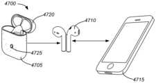
이어버드 및 케이스의 무선 페어링:Wireless pairing of earbuds and case:
일부 실시예들에서, 무선 통신장치를 포함하는 휴대용 청취 디바이스를 위한 케이스는: 휴대용 청취 디바이스를 위한 수용 영역을 갖는 하우징; 하우징에 부착되는 덮개 - 덮개는 덮개가 휴대용 청취 디바이스를 케이스 내에 숨기는 폐쇄 위치와, 사용자로 하여금 수용 영역으로부터 휴대용 청취 디바이스를 꺼내도록 허용하는 개방 위치 사이에서 작동가능함 -; 수용 영역 내에 위치된 전기 커넥터 - 전기 커넥터는 휴대용 청취 디바이스가 수용 영역 내에 수용된 경우 하나 이상의 디바이스 전기 접촉부들에 전기적으로 연결되는 하나 이상의 케이스 전기 접촉부를 가짐 -; 사용자-생성 동작에 응답한 신호를 생성하도록 구성된 입력 디바이스; 및 입력 디바이스 및 전기 커넥터에 결합된 프로세서를 포함할 수 있다. 프로세서는 입력 디바이스로부터의 신호를 수신하고, 이에 응답하여, 전기 커넥터를 통해 휴대용 청취 디바이스와 호스트 전자 디바이스의 무선 페어링을 개시하도록 휴대용 청취 디바이스에 명령어를 전송하도록 구성될 수 있다. 일부 인스턴스들에서, 프로세서는 호스트 전자 디바이스에 대한 휴대용 청취 디바이스의 무선 페어링을 개시하도록 휴대용 청취 디바이스에 명령어를 전송하기 전에, 입력 디바이스로부터 신호를 수신한 것에 응답하여 무선 통신장치를 턴 온(ON) 시키기 위한 명령어를 전기 커넥터를 통해 휴대용 청취 디바이스에 수신 전송하도록 추가로 구성될 수 있다.In some embodiments, a case for a portable listening device including a wireless communication device may include: a housing having a receiving area for the portable listening device; a cover attached to the housing, the cover being operable between a closed position where the cover encloses the portable listening device within the case and an open position where the cover allows a user to remove the portable listening device from the receiving area; an electrical connector positioned within the receiving area, the electrical connector having one or more case electrical contacts that are electrically connected to one or more device electrical contacts when the portable listening device is received within the receiving area; an input device configured to generate a signal in response to a user-generated action; and a processor coupled to the input device and the electrical connector. The processor may be configured to receive a signal from the input device and, in response, transmit a command to the portable listening device via the electrical connector to initiate wireless pairing of the portable listening device with a host electronic device. In some instances, the processor may be further configured to transmit, via the electrical connector, a command to the portable listening device to turn ON the wireless communication device in response to receiving a signal from the input device prior to transmitting a command to the portable listening device to initiate wireless pairing of the portable listening device with the host electronic device.
일부 실시예들에서, 제1 전자 디바이스를 제2 전자 디바이스에 무선으로 페어링하기 위한 방법이 제공된다. 방법은: 제1 및 제2 디바이스와 상이한 제3 전자 디바이스의 사용자로부터 입력을 수신하는 단계를 포함할 수 있다. 입력을 수신한 것에 응답하여, 제3 전자 디바이스는 제3 및 제1 전자 디바이스 사이의 유선 연결을 통해 제1 전자 디바이스로 사용자 입력 신호를 통신할 수 있다. 제1 전자 디바이스가 사용자 입력 신호를 수신한 것에 응답하여, 제1 전자 디바이스는 무선 페어링 요청을 브로드캐스트할 수 있으며, 무선 페어링 요청을 수신한 것에 응답하여, 제2 전자 디바이스는 제1 디바이스와 무선으로 페어링될 수 있다. 일부 인스턴스들에서, 제1 전자 디바이스는 무선 헤드폰 세트일 수 있으며, 제2 전자 디바이스는 이동 전자 디바이스이고, 제3 전자 디바이스는 휴대용 청취 디바이스를 위한 케이스일 수 있다. 또한, 제3 전자 디바이스가 휴대용 청취 디바이스를 위한 케이스인 일부 실시예들에서, 사용자로부터의 입력은 케이스의 덮개를 개방하는 것일 수 있다.In some embodiments, a method for wirelessly pairing a first electronic device to a second electronic device is provided. The method may include: receiving input from a user of a third electronic device, different from the first and second devices. In response to receiving the input, the third electronic device may communicate a user input signal to the first electronic device via a wired connection between the third and first electronic devices. In response to the first electronic device receiving the user input signal, the first electronic device may broadcast a wireless pairing request, and in response to receiving the wireless pairing request, the second electronic device may wirelessly pair with the first device. In some instances, the first electronic device may be a set of wireless headphones, the second electronic device may be a mobile electronic device, and the third electronic device may be a case for a portable listening device. Further, in some embodiments where the third electronic device is a case for a portable listening device, the input from the user may be opening a lid of the case.
이어버드를 위한 리셉터클 커넥터를 구비한 이어버드 케이스:Earbud case with receptacle connector for earbuds:
일부 실시예들에서, 한 쌍의 이어버드를 위한 케이스가 제공되며, 여기서 각각의 이어버드는 이어 부분 및 지주(stem) 부분 - 지주 부분은 지주부분의 원위 단부에 배치된 전기 커넥터를 구비함 - 을 갖는다. 케이스는: 하우징; 하우징 내에 위치된 삽입부 - 삽입부는 각각 제1 및 제2 이어버드를 수용하도록 크기 및 형상이 정해진 제1 및 제2 공동을 가지고, 제1 및 제2 공동 각각은 공동 내로 이어버드를 수용하기 위한 수용 개구, 및 수용 개구에 대향하는 접촉 개구를 가짐 -; 및 삽입부에 부착된 접촉 조립체 - 접촉 조립체는 제1 공동 내로 연장되는 제1 쌍의 전기 접촉부 및 제2 공동 내로 연장되는 제2 쌍의 전기 접촉부를 포함하며, 제1 및 제2 쌍의 전기 접촉부는 각각 접촉 개구를 통해 제1 및 제2 이어버드의 원위 단부에 배치된 전기 커넥터와 전기 접촉부를 이루도록 구성됨 - 를 포함할 수 있다.In some embodiments, a case is provided for a pair of earbuds, wherein each earbud has an ear portion and a stem portion, the stem portion having an electrical connector disposed at a distal end of the stem portion. The case may include: a housing; an insert positioned within the housing, the insert having first and second cavities sized and shaped to receive first and second earbuds, respectively, each of the first and second cavities having a receiving opening for receiving the earbuds within the cavities and a contact opening opposite the receiving opening; and a contact assembly attached to the insert, the contact assembly including a first pair of electrical contacts extending into the first cavity and a second pair of electrical contacts extending into the second cavity, the first and second pairs of electrical contacts being configured to make electrical contact with electrical connectors disposed at distal ends of the first and second earbuds, respectively, through the contact openings.
전자 접촉부를 구비한 무선 이어버드:Wireless earbuds with electronic contacts:
일부 실시예들에서, 무선 이어버드가 제공되며, 이는: 종축에 대해 정렬된 지주 부분 - 지주 부분은 제1 및 제2 단부를 포함함 - 을 갖는 하우징; 드라이버 유닛, 및 제1 단부에 근접하고 종축으로부터 오프셋된 지향성 사운드 포트를 갖는 스피커 어셈블리 - 드라이버 유닛은 지향성 사운드 포트로부터의 음을 방출하도록 정렬되고, 자석, 음성 코일, 및 진동판을 포함함 -; 하우징 내에 배치된 재충전가능한 배터리; 및 지주 부분의 제2 단부에서 외부 표면에 노출되고 재충전가능한 배터리에 전력을 제공하도록 전기적으로 결합된 제1 및 제2 외부 접촉부를 포함한다. 제1 및 제2 외부 접촉부는 각각 부분적으로 환형 형상을 가질 수 있으며 대향 대칭 관계를 가지고 서로에 대하여 이격될 수 있다. 일부 실시예들에서, 제1 및 제2 외부 접촉부의 외부 둘레는 지주 부분의 외부 표면과 동일 평면을 이룬다.In some embodiments, a wireless earbud is provided, comprising: a housing having a longitudinally aligned stem portion, the stem portion including first and second ends; a speaker assembly having a driver unit and a directional sound port proximate the first end and offset from the longitudinal axis, the driver unit being aligned to emit sound from the directional sound port and including a magnet, a voice coil, and a diaphragm; a rechargeable battery disposed within the housing; and first and second external contacts, the first and second external contacts being exposed on an exterior surface at the second end of the stem portion and electrically coupled to provide power to the rechargeable battery. The first and second external contacts can each have a partially annular shape and can be spaced apart from one another in an orthogonal symmetrical relationship. In some embodiments, an outer perimeter of the first and second external contacts is flush with an exterior surface of the stem portion.
일부 실시예들에서, 무선 이어버드는: 하우징; 하우징 내에 배치된 재충전가능한 배터리; 드라이버 유닛 및 지향성 사운드 포트를 포함하는 스피커 어셈블리 - 드라이버 유닛은 지향성 사운드 포트로부터의 음을 방출하도록 정렬되고, 자석, 음성 코일, 및 진동판을 포함함 -; 및 하우징의 외부 표면에 노출된 복수의 접촉부 - 복수의 접촉부 내의 각각의 접촉부는 각각의 접촉부의 외부 표면에 이원계 금속 합금 도금층을 갖는 전도성 기부(base)를 포함함 - 를 포함하며, 이원계 금속 합금 도금층은 로듐 및 루테늄을 포함한다. 일부 인스턴스들에서, 로듐의 중량 퍼센트는 적어도 85 퍼센트로, 잔량은 루테늄이다.In some embodiments, a wireless earbud comprises: a housing; a rechargeable battery disposed within the housing; a speaker assembly including a driver unit and a directional sound port, the driver unit being aligned to emit sound from the directional sound port and including a magnet, a voice coil, and a diaphragm; and a plurality of contacts exposed on an exterior surface of the housing, each contact within the plurality of contacts including a conductive base having a binary metal alloy plating layer on an exterior surface of each contact, the binary metal alloy plating layer comprising rhodium and ruthenium. In some instances, the weight percent of rhodium is at least 85 percent, with the remainder being ruthenium.
공동 내부의 이어버드의 자기 유지:Self-retention of the earbud within the cavity:
본 개시내용의 일부 실시예들은 하나 이상의 이어버드 자기 컴포넌트를 갖는 이어버드를 위한 케이스에 관한 것이다. 케이스는: 이어버드를 수용하도록 크기 및 형상이 정해진 수용 공동; 케이스 내에 배치되고 이어버드를 수용 공동 내로, 그리고 제2 이어버드를 제2 수용 공동 내로 자기적으로 끌어당기고 자기적으로 고정하도록 위치되고 구성된 하나 이상의 하우징 자기 컴포넌트; 및 덮개 - 덮개는 수용 공동이 노출되는 개방 위치와 덮개가 수용 공동을 덮는 폐쇄 위치 사이에서 작동가능함 - 를 포함할 수 있다. 케이스는 한 쌍의 이어버드를 보관하도록 구성될 수 있고, 수용 공동은 한 쌍의 이어버드들 중 제1 이어버드를 수용하도록 크기 및 형상이 정해지는 제1 수용 공동, 및 한 쌍의 이어버드들 중 제2 이어버드를 수용하도록 크기 및 형상이 정해지는 제2 수용 공동을 포함한다. 일부 실시예들에서, 하나 이상의 하우징 자기 컴포넌트는 제1 수용 공동 둘레로 배치되고 제1 수용 공동 내에 제1 이어버드를 자기적으로 끌어당기고 자기적으로 유지하도록 구성된 제1 복수의 자기 컴포넌트, 및 제2 수용 공동 둘레로 배치되고 제2 수용 공동 내부로 제2 이어버드를 자기적으로 끌어당기고 자기적으로 유지하도록 구성된 제2 복수의 자기 컴포넌트를 포함할 수 있다.Some embodiments of the present disclosure relate to a case for earbuds having one or more earbud magnetic components. The case can include: a receiving cavity sized and shaped to receive an earbud; one or more housing magnetic components disposed within the case and positioned and configured to magnetically attract and magnetically secure an earbud into the receiving cavity and a second earbud into the second receiving cavity; and a lid, the lid being operable between an open position in which the receiving cavity is exposed and a closed position in which the lid covers the receiving cavity. The case can be configured to store a pair of earbuds, the receiving cavity including a first receiving cavity sized and shaped to receive a first earbud of the pair of earbuds, and a second receiving cavity sized and shaped to receive a second earbud of the pair of earbuds. In some embodiments, the one or more housing magnetic components may include a first plurality of magnetic components disposed around the first receiving cavity and configured to magnetically attract and magnetically retain a first earbud within the first receiving cavity, and a second plurality of magnetic components disposed around the second receiving cavity and configured to magnetically attract and magnetically retain a second earbud within the second receiving cavity.
일부 실시예들에서, 이어버드는: 사용자의 귀 내에 적어도 부분적으로 들어맞도록 형성된 하우징; 하우징 내에 형성된 지향성 사운드 포트; 하우징 내에 배치되고 제1 자석을 포함한 드라이버 유닛을 포함한 스피커 어셈블리 - 드라이버 유닛은 지향성 사운드 포트로부터의 음을 방출하도록 정렬됨 -; 스피커 어셈블리로부터 분리되고 하우징 내에 위치된 자기 유지 컴포넌트를 포함한다. 하우징은 이어 부분 및 지주 부분을 가질 수 있고, 자기 유지 컴포넌트는 이어 부분 내에 배치될 수 있다. 드라이버 유닛은 진동판 및 음성 코일을 포함할 수 있고, 제1 자석은 음성 코일에 작동가능하게 결합됨으로써 전자 신호에 응답하여 진동판을 이동시킬 수 있으며, 자기 유지 컴포넌트는 음성 코일에 작동가능하게 결합되지 않는다.In some embodiments, an earbud includes: a housing configured to fit at least partially within an ear of a user; a directional sound port formed within the housing; a speaker assembly disposed within the housing and including a driver unit including a first magnet, the driver unit being aligned to emit sound from the directional sound port; and a magnetic retention component separate from the speaker assembly and positioned within the housing. The housing can have an ear portion and a stem portion, and the magnetic retention component can be disposed within the ear portion. The driver unit can include a diaphragm and a voice coil, the first magnet being operably coupled to the voice coil to move the diaphragm in response to an electronic signal, and the magnetic retention component is not operably coupled to the voice coil.
일부 실시예들에서, 무선 청취 시스템이 제공되며, 위에 기술된 케이스 및 한 쌍의 이어버드를 포함한다.In some embodiments, a wireless listening system is provided, comprising a case as described above and a pair of earbuds.
휴대용 디바이스를 충전하기 위한 유도 충전 전송기를 구비한 케이스:Case with inductive charging transmitter for charging portable devices:
일부 실시예들에서, 휴대용 청취 디바이스를 위한 케이스는: 휴대용 청취 디바이스를 수용하도록 구성된 하나 이상의 공동 및 외부 충전 표면을 갖는 하우징; 하우징에 부착된 덮개 - 덮개는 하나 이상의 공동 위에 덮개가 정렬되는 폐쇄 위치와, 하나 이상의 공동으로부터 덮개가 변위되는 개방 위치 사이에서 작동가능함 -; 배터리; 하나 이상의 공동 내에 위치된 경우 휴대용 청취 디바이스를 충전하도록 구성된 제1 충전 시스템; 및 외부 충전 표면에 인접하게 하우징 내에 위치된 전송 코일을 포함하는 제2 충전 시스템 - 전송 코일은 외부 충전 표면에 인접한 하우징 외부에 위치된 전자 디바이스의 전력 수신 코일에 전력을 무선으로 전송하도록 구성됨 - 을 포함한다. 일부 실시예들에서, 휴대용 청취 디바이스는 한 쌍의 이어버드를 위한 케이스일 수 있고; 하우징은 각각 제1 및 제2 이어버드를 수용하도록 구성된 제1 및 제2 공동을 포함할 수 있으며; 제1 충전 시스템은 이어버드가 제1 및 제2 공동 내에 위치된 경우 제1 및 제2 이어버드를 충전하도록 구성될 수 있다.In some embodiments, a case for a portable listening device includes: a housing having one or more cavities configured to receive the portable listening device and an exterior charging surface; a cover attached to the housing, the cover being operable between a closed position in which the cover is aligned over the one or more cavities and an open position in which the cover is displaced from the one or more cavities; a battery; a first charging system configured to charge the portable listening device when positioned within the one or more cavities; and a second charging system including a transmitting coil positioned within the housing adjacent to the exterior charging surface, the transmitting coil configured to wirelessly transmit power to a power receiving coil of an electronic device positioned outside the housing adjacent to the exterior charging surface. In some embodiments, the portable listening device can be a case for a pair of earbuds; the housing can include first and second cavities configured to receive first and second earbuds, respectively; and the first charging system can be configured to charge the first and second earbuds when the earbuds are positioned within the first and second cavities.
방수 리셉터클 커넥터:Waterproof receptacle connector:
일부 실시예들에서, 전기 리셉터클 커넥터가 개시되며, 이는: 수용 면과 후방 면 사이에 연장된 전기적으로 절연된 중합체를 포함하는 하우징 - 하우징은 정합 플러그 커넥터의 플러그 부분을 수용하기 위한 수용 면 내의 개구와 연통되는 공동을 정의함 -; 후방 면에 인접하게 위치된 접촉 스페이서; 하우징의 후방 면과 접촉 조립체 사이에 배치된 개스킷(gasket); 복수의 접촉부 - 복수의 접촉부 각각은 공동 내에 위치된 팁, 각각의 접촉부를 접촉 스페이서에 앵커링(anchor)시키는 앵커 부분, 및 팁을 앵커 부분에 연결하는 빔 부분을 가짐 -; 및 하우징의 외부 표면 둘레로 배치되는 금속 브라켓을 포함한다.In some embodiments, an electrical receptacle connector is disclosed, comprising: a housing including an electrically insulating polymer extending between a receiving face and a rear face, the housing defining a cavity communicating with an opening in the receiving face for receiving a plug portion of a mating plug connector; a contact spacer positioned adjacent the rear face; a gasket positioned between the rear face of the housing and a contact assembly; a plurality of contacts, each of the plurality of contacts having a tip positioned within the cavity, an anchor portion anchoring each contact to the contact spacer, and a beam portion connecting the tip to the anchor portion; and a metal bracket disposed around an outer surface of the housing.
용량성 터치 센서를 구비한 이어버드:Earbuds with capacitive touch sensors:
일부 실시예들은 이어버드에 관한 것으로, 이어버드는: 이어버드의 하나 이상의 전기적 컴포넌트가 내부에 하우징되는 공동을 정의하는 하우징 - 하우징은 하우징의 외부 표면에, 그리고 외부 표면에 대향하는 공동 내의 내부 표면에 터치 감응 영역을 가짐 -; 금속화된 회로부가 상부에 형성된 제1 표면을 갖는 용량성 센서 삽입부 - 금속화된 회로부는 하우징 내에 위치됨으로써 제1 표면이 하우징의 내부 표면에 인접하게 됨 -; 하우징 내에 배치된 이어버드 프로세서; 및 용량성 센서 삽입부를 이어버드 프로세서에 전기적으로 결합하는 적어도 하나의 전도체를 포함한다. 용량성 센서 삽입부는 하우징의 형상에 밀접하게 부합하도록 형성될 수 있다. 일부 인스턴스들에서, 금속화된 회로부는 사용자에 의해 터치된 경우, 검출될 수 있는 부하를 자기-정전용량 회로부에 거는 적어도 하나의 자기-정전용량 센서를 형성한다. 다른 인스턴스들에서, 금속화된 회로부는 적어도 하나의 상호-정전용량 센서를 형성하는 행 및 열 전극들을 포함하며, 사용자에 의해 터치될 경우, 행 및 열 전극들 사이의 상호 커플링이 변화되어 검출된다. 용량성 센서 삽입부는 금속성 미립자들을 포함하는 플라스틱으로 형성된다.Some embodiments relate to an earbud, comprising: a housing defining a cavity in which one or more electrical components of the earbud are housed, the housing having a touch-sensitive area on an exterior surface of the housing and an interior surface within the cavity opposite the exterior surface; a capacitive sensor insert having a first surface formed thereon with metallized circuitry, the metallized circuitry positioned within the housing such that the first surface is adjacent the interior surface of the housing; an earbud processor disposed within the housing; and at least one conductor electrically coupling the capacitive sensor insert to the earbud processor. The capacitive sensor insert can be formed to closely conform to a shape of the housing. In some instances, the metallized circuitry forms at least one self-capacitance sensor that, when touched by a user, applies a detectable load to the self-capacitance circuitry. In other instances, the metallized circuitry includes row and column electrodes forming at least one mutual-capacitance sensor, wherein, when touched by a user, a change in mutual coupling between the row and column electrodes is detected. The capacitive sensor insert is formed of a plastic containing metallic particles.
비틀림 스프링 오버센터 메커니즘을 구비한 케이스:Case with torsion spring over-center mechanism:
일부 실시예들에서, 청취 디바이스를 위한 케이스는: 청취 디바이스를 수용하기 위한 공동을 갖는 하우징; 피벗 가능한 연결부를 이용하여 하우징에 부착되는 덮개 - 피벗 가능한 연결부는 덮개가 공동 위에 정렬되는 폐쇄 위치와, 덮개가 각을 이루며 변위됨으로써 청취 디바이스가 공동으로부터 꺼내질 수 있게 하는 개방 위치 사이에서 덮개가 회전하도록 허용함 -; 및 덮개에 부착되고, 덮개로부터 피벗 가능한 연결부의 대향 측면 상에 배치된 연장부를 포함한, 덮개를 위한 오버센터 메커니즘 - 연장부는 덮개가 오버센터 위치를 지나 이동할(이때 덮개는 이어서 폐쇄 위치로 추진됨) 때까지 개방 위치로부터 폐쇄 위치로 회전하는 덮개에 저항하는 아암과 접촉되어 있음 - 을 포함한다.In some embodiments, a case for a listening device comprises: a housing having a cavity for receiving the listening device; a cover attached to the housing using a pivotable connection, the pivotable connection allowing the cover to rotate between a closed position, in which the cover is aligned over the cavity, and an open position in which the cover is angled and displaced such that the listening device can be removed from the cavity; and an over-center mechanism for the cover, the over-center mechanism including an extension attached to the cover and disposed on an opposite side of the pivotable connection from the cover, the extension contacting an arm that resists rotation of the cover from the open position to the closed position until the cover is moved past the over-center position (wherein the cover is subsequently propelled to the closed position).
본 개시내용의 특성 및 이점을 더욱 명확하게 이해하기 위해, 하기의 설명 및 첨부 도면이 참조되어야 한다. 그러나, 도면들 각각은 단지 예시의 목적으로 제공되고, 본 개시내용의 범주의 한계의 한정으로 의도되지 않는 것이 이해되어야 한다. 또한, 일반적으로, 그리고 설명으로부터 반대인 것이 명백하지 않은 한, 상이한 도면들의 요소들이 동일한 도면 부호들을 사용하는 경우에, 요소들은 기능 또는 목적에 있어서 대체로 동일하거나 적어도 유사하다.In order to more clearly understand the nature and advantages of the present disclosure, reference should be made to the following description and the accompanying drawings. It should be understood, however, that each of the drawings is provided for the purpose of illustration only and is not intended to limit the scope of the present disclosure. Also, in general, and unless it is obvious to the contrary from the description, where elements in different drawings use the same drawing reference numerals, the elements are substantially identical or at least similar in function or purpose.
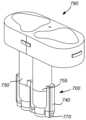
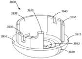
도 1은 본 개시내용의 실시예들에 따라 덮개를 가지며, 한 쌍의 이어버드를 유지하도록 구성된 케이스의 측면도.
도 2는 본 개시내용의 일부 실시예들에 따라 한 쌍의 이어버드에 결합된 충전 시스템을 구비한 케이스의 시스템 레벨 다이어그램.
도 3은 도 1에 도시된 케이스의 단순화된 단면도.
도 4a는 본 개시내용의 일 실시예에 따른 이어버드 커넥터의 부분 단면도.
도 4b는 도 4a에 예시된 이어버드 커넥터의 평면도.
도 5a는 본 개시내용에 따른 이어버드 커넥터의 다른 실시예의 부분 단면도.
도 5b는 도 5a에 예시된 이어버드 커넥터의 평면도.
도 6a는 본 개시내용에 따른 이어버드 커넥터의 다른 실시예의 부분 단면도.
도 6b는 도 6a에 예시된 이어버드 커넥터의 평면도.
도 6c는 도 6a에 예시된 이어버드 커넥터를 위한 커넥터 어셈블리의 분해 등각도.
도 6d는 도 6a에 예시된 조립된 이어버드 커넥터의 등각도.
도 7a는 본 개시내용에 따른 이어버드 커넥터의 다른 실시예의 분해 등각도.
도 7b는 도 7a에 예시된 조립된 이어버드 커넥터의 등각도.
도 8a는 본 개시내용에 따른 이어버드 커넥터의 다른 실시예의 부분 단면도.
도 8b는 도 8a에 예시된 이어버드 상의 커넥터의 평면도.
도 8c는 도 8a에 예시된 이어버드 커넥터의 분해 등각도.
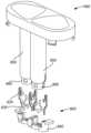
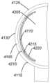
도 9a 및 도 9b는 각각 도 1에 도시된 이어버드 중 하나의 전면 등각도 및 후면 등각도.
도 10은 케이스 덮개가 제거된 도 1에 도시된 케이스의 평면도.
도 11은 도 10의 단면 A-A를 따라 예시된 케이스 내부의 공동 내에 보유된 이어버드의 부분 단면도.
도 12는 도 10의 단면 B-B를 따라 예시된 케이스 내부의 공동 내에 보유된 이어버드의 부분 단면도.
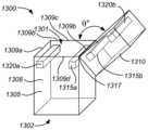
도 13은 본 개시내용의 일부 실시예들에 따른 오버센터 덮개를 가진 케이스의 등각도.
도 14는 오버센터 덮개가 개방 위치에 있는 도 13에 도시된 케이스의 등각도.
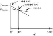
도 15는 본 개시내용의 일부 실시예들에 따른 오버센터 덮개와 연관된 인력 및 반발력을 도시한 그래프.
도 16은 본 개시내용의 일부 실시예들에 따른, 오정렬된 폴을 구비한 한 쌍의 자석 및 이들을 둘러싸는 고투과성 물질을 구비한 한 쌍을 포함한 케이스의 측면도.
도 17은 본 개시내용의 일부 실시예들에 따른, 스프링에 부착된 두 쌍의 자석을 포함한 케이스의 측면도.
도 18은 본 개시내용의 일부 실시예들에 따른 케이스 내에 이용될 수 있는 자석의 등각도.
도 19는 본 개시내용의 일부 실시예들에 따른 케이스 내에 이용될 수 있는 자석의 등각도.
도 20은 본 개시내용의 일부 실시예들에 따른 케이스 내에 이용될 수 있는 자석의 등각도.
도 21은 본 개시내용의 일부 실시예들에 따른 케이스 내에 이용될 수 있는 자석의 등각도.
도 22a는 본 개시내용의 일부 실시예들에 따른, 그의 덮개가 폐쇄된 비틀림 스프링 오버센터 메커니즘을 구비한 케이스의 측면도.
도 22b는 도 22a에 예시된 비틀림 스프링 오버센터 메커니즘의 등각도.
도 22c는 그의 덮개가 부분적으로 개방된 도 22a에 예시된 케이스의 측면도.
도 22d는 그의 덮개가 추가적으로 개방된 도 22a에 예시된 케이스의 측면도.
도 23은 본 개시내용의 실시예들에 따른 무선 충전 시스템의 단순화된 사시도.
도 24는 일부 실시예들에 따른, 도 23에 예시된 충전 시스템의 일부가 될 수 있는 유도 전력 수신 시스템의 블록도.
도 25는 도 23에 예시된 이어버드 케이스의 단순화된 평면도.
도 26은 도 23에 예시된 유도 전력 전송 시스템의 일 실시예의 블록도.
도 27은 본 개시내용의 일부 실시예들에 따른 유도 충전 시스템 상의 유도적으로 충전된 케이스의 단순화된 등각도.
도 28은 본 개시내용의 일부 실시예들에 따른, 도 1에 예시된 케이스 내에 포함될 수 있는 전기 커넥터의 등각도.
도 29는 도 28에 예시된 전기 커넥터의 분해 등각도.
도 30은 본 개시내용의 일부 실시예들에 따른 좌측 이어버드의 전면 및 후면 등각도.
도 31은 본 개시내용의 일부 실시예들에 따른 우측 이어버드의 전면 및 후면 등각도.
도 32는 도 30 및 도 31에 예시된 이어버드 중 하나의 단면도.
도 33은 도 30 및 도 31에 예시된 이어버드 중 일부 컴포넌트가 제거된 하나의 이어버드의 단면도.
도 34는 본 개시내용의 일부 실시예들에 따른 이어버드 내에 이용될 수 있는 가요성 회로 기판의 평면도.
도 35는 도 34에 예시된 가요성 회로 기판의 등각도.
도 36은 도 30 및 도 31에 예시된 이어버드 내에 포함될 수 있는 커넥터 구조물의 등각도.
도 37은 본 개시내용의 일부 실시예들에 따른, 도 36에 예시된 커넥터 구조물을 위한 접촉부의 등각도.
도 38은 도 36에 예시된 접촉 구조물의 등각도.
도 39는 본 개시내용의 일 실시예에 따른 이어버드 커넥터 접촉부의 등각도.
도 40은 도 39에 예시되었던 인서트 성형된 커넥터 접촉부의 등각도.
도 41은 본 개시내용의 일부 실시예들에 따른 용량성 센서 삽입부를 구비한 이어버드의 등각도.
도 42는 도 41에 예시된 이어버드 및 용량성 센서 삽입부의 단면도.
도 43은 본 개시내용의 일 실시예에 따라 예시된 용량성 센서 삽입부의 평면도.
도 44는 본 개시내용의 일 실시예에 따라 예시된 용량성 센서 삽입부의 평면도.
도 45a는 본 개시내용의 일 실시예에 따른 음향 삽입부를 구비한 이어버드를 예시한 도.
도 45b는 도 45a에 예시된 음향 삽입부를 구비한 이어버드를 예시한 도.
도 46은 본 개시내용의 일부 실시예들에 따른 이어버드의 제조와 연관된 단계들을 예시한 흐름도.
도 47은 본 개시내용의 일부 실시예들에 따른 시스템(47)을 예시한 도.
도 48은 본 개시내용의 일부 실시예들에 따른 시스템(4800)의 단순화된 블록도.
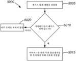
도 49는 본 개시내용의 일부 실시예들에 따른 무선 헤드폰과 호스트 디바이스와의 페어링과 연관된 단계들을 예시한 흐름도.
도 50은 본 개시내용의 일부 실시예들에 따른 이어버드 내의 무선 통신장치를 활성화하는 것과 연관된 단계들을 예시한 흐름도.
도 51은 본 개시내용의 일부 실시예들에 따른 이어버드 내의 무선 통신장치를 비활성화하는 것과 연관된 단계들을 예시한 흐름도.FIG. 1 is a side view of a case having a cover and configured to hold a pair of earbuds according to embodiments of the present disclosure.
FIG. 2 is a system level diagram of a case having a charging system coupled to a pair of earbuds according to some embodiments of the present disclosure.
Figure 3 is a simplified cross-sectional view of the case illustrated in Figure 1.
FIG. 4A is a partial cross-sectional view of an earbud connector according to one embodiment of the present disclosure.
Figure 4b is a plan view of the earbud connector illustrated in Figure 4a.
FIG. 5A is a partial cross-sectional view of another embodiment of an earbud connector according to the present disclosure.
Figure 5b is a plan view of the earbud connector illustrated in Figure 5a.
FIG. 6A is a partial cross-sectional view of another embodiment of an earbud connector according to the present disclosure.
Fig. 6b is a plan view of the earbud connector illustrated in Fig. 6a.
FIG. 6c is an exploded isometric view of a connector assembly for the earbud connector illustrated in FIG. 6a.
FIG. 6d is an isometric view of the assembled earbud connector illustrated in FIG. 6a.
FIG. 7a is an exploded isometric view of another embodiment of an earbud connector according to the present disclosure.
FIG. 7b is an isometric view of the assembled earbud connector illustrated in FIG. 7a.
FIG. 8A is a partial cross-sectional view of another embodiment of an earbud connector according to the present disclosure.
FIG. 8b is a plan view of the connector on the earbud illustrated in FIG. 8a.
Figure 8c is an exploded isometric view of the earbud connector illustrated in Figure 8a.
FIGS. 9A and 9B are front isometric views and rear isometric views, respectively, of one of the earbuds illustrated in FIG. 1.
Figure 10 is a plan view of the case shown in Figure 1 with the case cover removed.
FIG. 11 is a partial cross-sectional view of an earbud held within a cavity within the case illustrated along section AA of FIG. 10.
FIG. 12 is a partial cross-sectional view of an earbud held within a cavity within the case illustrated along section BB of FIG. 10.
FIG. 13 is an isometric view of a case having an over-center cover according to some embodiments of the present disclosure.
Figure 14 is an isometric view of the case shown in Figure 13 with the overcenter cover in the open position.
FIG. 15 is a graph illustrating attractive and repulsive forces associated with an overcenter cover according to some embodiments of the present disclosure.
FIG. 16 is a side view of a case including a pair of magnets having misaligned poles and a pair of highly permeable materials surrounding them, according to some embodiments of the present disclosure.
FIG. 17 is a side view of a case including two pairs of magnets attached to springs, according to some embodiments of the present disclosure.
FIG. 18 is an isometric view of a magnet that may be used within a case according to some embodiments of the present disclosure.
FIG. 19 is an isometric view of a magnet that may be used within a case according to some embodiments of the present disclosure.
FIG. 20 is an isometric view of a magnet that may be used within a case according to some embodiments of the present disclosure.
FIG. 21 is an isometric view of a magnet that may be used within a case according to some embodiments of the present disclosure.
FIG. 22A is a side view of a case having a torsion spring overcenter mechanism with its lid closed, according to some embodiments of the present disclosure.
Figure 22b is an isometric view of the torsion spring overcenter mechanism illustrated in Figure 22a.
Figure 22c is a side view of the case illustrated in Figure 22a with its cover partially open.
FIG. 22d is a side view of the case illustrated in FIG. 22a with its cover additionally opened.
FIG. 23 is a simplified perspective view of a wireless charging system according to embodiments of the present disclosure.
FIG. 24 is a block diagram of an inductive power receiving system that may be part of the charging system illustrated in FIG. 23, according to some embodiments.
Fig. 25 is a simplified plan view of the earbud case illustrated in Fig. 23.
FIG. 26 is a block diagram of one embodiment of the inductive power transmission system illustrated in FIG. 23.
FIG. 27 is a simplified isometric view of an inductively charged case on an inductive charging system according to some embodiments of the present disclosure.
FIG. 28 is an isometric view of an electrical connector that may be included within the case illustrated in FIG. 1, according to some embodiments of the present disclosure.
Fig. 29 is an exploded isometric view of the electrical connector illustrated in Fig. 28.
FIG. 30 is a front and rear isometric view of a left earbud according to some embodiments of the present disclosure.
FIG. 31 is a front and rear isometric view of a right earbud according to some embodiments of the present disclosure.
FIG. 32 is a cross-sectional view of one of the earbuds illustrated in FIGS. 30 and 31.
FIG. 33 is a cross-sectional view of one earbud with some of the components of the earbuds illustrated in FIGS. 30 and 31 removed.
FIG. 34 is a plan view of a flexible circuit board that may be used in earbuds according to some embodiments of the present disclosure.
Fig. 35 is an isometric view of the flexible circuit board illustrated in Fig. 34.
FIG. 36 is an isometric view of a connector structure that may be included within the earbuds illustrated in FIGS. 30 and 31.
FIG. 37 is an isometric view of a contact portion for the connector structure illustrated in FIG. 36, according to some embodiments of the present disclosure.
Fig. 38 is an isometric view of the contact structure illustrated in Fig. 36.
FIG. 39 is an isometric view of an earbud connector contact portion according to one embodiment of the present disclosure.
Fig. 40 is an isometric view of the insert-molded connector contact portion illustrated in Fig. 39.
FIG. 41 is an isometric view of an earbud having a capacitive sensor insert according to some embodiments of the present disclosure.
Fig. 42 is a cross-sectional view of the earbud and capacitive sensor insert illustrated in Fig. 41.
FIG. 43 is a plan view of a capacitive sensor insert exemplified according to one embodiment of the present disclosure.
FIG. 44 is a plan view of a capacitive sensor insert exemplified according to one embodiment of the present disclosure.
FIG. 45A is a diagram illustrating an earbud having an acoustic insert according to one embodiment of the present disclosure.
FIG. 45b is a drawing illustrating an earbud having an acoustic insert illustrated in FIG. 45a.
FIG. 46 is a flowchart illustrating steps associated with the manufacture of earbuds according to some embodiments of the present disclosure.
FIG. 47 is a diagram illustrating a system (47) according to some embodiments of the present disclosure.
FIG. 48 is a simplified block diagram of a system (4800) according to some embodiments of the present disclosure.
FIG. 49 is a flowchart illustrating steps associated with pairing a wireless headphone with a host device according to some embodiments of the present disclosure.
FIG. 50 is a flowchart illustrating steps associated with activating a wireless communication device within an earbud according to some embodiments of the present disclosure.
FIG. 51 is a flowchart illustrating steps associated with disabling a wireless communication device within an earbud according to some embodiments of the present disclosure.
본 개시내용의 일부 실시예들은 휴대용 청취 디바이스, 및 이러한 디바이스들을 수용하고/하거나 충전하기 위한 케이스들에 관한 것으로, 이들은 케이스 및/또는 휴대용 청취 디바이스의 이용과 연관된 사용자 경험을 개선시킬 수 있는 개선된 특징부들을 갖는다. 본 개시내용이 광범위한 휴대용 청취 디바이스에 유용할 수 있는 반면, 본 개시내용의 일부 실시예들은 아래에 상세히 기술되는 바와 같이, 특히 무선 이어버드 및 무선 이어버드를 위한 케이스에 유용하다.Certain embodiments of the present disclosure relate to portable listening devices, and cases for housing and/or charging such devices, having improved features that may improve the user experience associated with use of the cases and/or portable listening devices. While the present disclosure may be useful for a wide range of portable listening devices, certain embodiments of the present disclosure are particularly useful for wireless earbuds and cases for wireless earbuds, as described in detail below.
예를 들어, 일부 실시예에서 한 쌍의 무선 이어버드는 재충전가능한 배터리 및 충전 회로부를 추가로 포함할 수 있는 케이스 내에 들어맞도록 크기 및 형상이 정해진다. 한 쌍의 이어버드는 케이스 내부의 이어버드 검출기가 이어버드가 케이스 내에 위치된 것을 검출할 경우 충전될 수 있다. 또한, 케이스는 덮개가 개방되었는지 검출할 수 있는 센서를 포함함으로써 각각의 이어버드 내부의 무선 통신장치가 활성화되어 사용자에 의해 사용될 준비가 되게 할 수 있다. 유사하게, 덮개가 폐쇄된 경우, 무선 통신장치가 차단됨으로써 이어버드 배터리 내의 전하가 보존되게 할 수 있다.For example, in some embodiments, a pair of wireless earbuds are sized and shaped to fit within a case that may additionally include a rechargeable battery and charging circuitry. The pair of earbuds may be charged when an earbud detector within the case detects that the earbuds are placed within the case. Additionally, the case may include a sensor that can detect whether the lid is opened, thereby causing the wireless radio within each earbud to be activated and ready for use by the user. Similarly, when the lid is closed, the wireless radio may be shut off, thereby conserving charge within the earbud batteries.
다른 예에서, 케이스는 이어버드를 페어링 모드에 진입시키도록 동작가능한 페어링 버튼을 케이스 상에 가질 수 있다. 추가의 예에서, 케이스는 케이스 배터리 내의 충전 레벨은 물론 각각의 이어버드의 충전 레벨에 대해 사용자에게 알리기 위한 하나 이상의 충전 표시광을 또한 가질 수 있다.In another example, the case may have a pairing button on the case that is operable to place the earbuds into pairing mode. In a further example, the case may also have one or more charge indicator lights to inform the user of the charge level of each earbud as well as the charge level within the case battery.
다른 예에서, 케이스는 오버센터 구성을 갖는 덮개를 가짐으로써, 덮개는 폐쇄 위치에 있을 때 제1 안정 위치에 있고 개방 위치에 있을 때 제2 안정 위치에 있지만, 폐쇄 위치와 개방 위치 사이에서는 불안정 위치에 있다. 일부 실시예들에서, 오버센터 구성은 두 쌍의 자석을 이용하여 달성될 수 있는 반면, 다른 실시예들에서는 비틀림 스프링을 이용하여 달성될 수 있다. 추가의 예들에서, 케이스는 그 내부에 케이스 내에 형성된 공동 내로 이어버드를 끌어당기고 사용자가 그들을 꺼내기 전까지 그들을 보유시키기 위한 하나 이상의 자석을 가질 수 있다.In another example, the case has a lid having an over-center configuration such that the lid is in a first stable position when in the closed position and in a second stable position when in the open position, but is in an unstable position between the closed and open positions. In some embodiments, the over-center configuration can be achieved using two pairs of magnets, while in other embodiments it can be achieved using a torsion spring. In further examples, the case can have one or more magnets therein to attract the earbuds into a cavity formed within the case and retain them until the user removes them.
다른 예에서, 케이스는 용액이 내부 회로부를 손상시키는 것을 방지하기 위해 액밀(liquid-tight)일 수 있다. 이어버드 재충전 및 케이스의 재충전 둘 모두를 위한 전기적 연결부는 액체에 의한 침투에 저항적일 수 있다.In another example, the case may be liquid-tight to prevent liquids from damaging the internal circuitry. Electrical connections for both earbud recharging and case recharging may be resistant to penetration by liquids.
다른 예에서, 이어버드는 이어버드 하우징 내 한정된 공간 내에 내부 스피커가 오디오 성능을 제공할 수 있도록 하는 베이스 포트 벤트(bass port vent) 및 배면 벤트와 같은 하나 이상의 음향 포트를 형성하는 음향 삽입부를 가질 수 있다.In another example, the earbud may have an acoustic insert that forms one or more acoustic ports, such as a bass port vent and a rear vent, that allow internal speakers to provide audio performance within a confined space within the earbud housing.
다른 예에서, 이어버드 케이스는 이어버드와 호스트 디바이스간의 블루투스® 페어링을 개시하기 위해 이용될 수 있다. 일 실시예에서 덮개 위치 센서는 덮개가 개방된 경우 이를 검출하고 이어버드의 페어링을 개시한다.In another example, the earbud case can be used to initiate Bluetooth® pairing between the earbuds and a host device. In one embodiment, a lid position sensor detects when the lid is open and initiates pairing of the earbuds.
본 개시내용에 따른 휴대용 청취 디바이스 및 그들의 케이스의 특징 및 양태를 보다 잘 이해하기 위해, 본 개시내용의 실시예들에 따른 이어버드 및 이어버드를 위한 케이스의 몇가지 특정 구현예를 들어 논의함에 의해, 아래 섹션에서 본 개시내용에 대한 추가적 문맥이 제공된다. 논의된 특정 실시예들은 다만 예시 용도일 뿐이며, 다른 실시예들이 다른 휴대용 청취 디바이스, 및 다른 휴대용 청취 디바이스는 물론 다른 디바이스들에 이용될 수 있는 케이스들 내에 채용될 수 있다.To better understand the features and aspects of the portable listening devices and their cases according to the present disclosure, the following sections provide additional context to the present disclosure by discussing several specific implementations of earbuds and cases for earbuds according to embodiments of the present disclosure. The specific embodiments discussed are for illustrative purposes only, and other embodiments may be employed within other portable listening devices, and cases that may be utilized with other portable listening devices, as well as other devices.
여기에 사용되는 바와 같이, 용어 "휴대용 청취 디바이스"는 사용자에게 들릴 수 있는 음을 재생하도록 설계된 임의의 휴대용 디바이스를 포함한다. 헤드폰은 하나의 유형의 휴대용 청취 디바이스이고, 휴대용 스피커는 다른 유형의 휴대용 청취 디바이스이다. 용어 "헤드폰"은 사용자의 머리 상부 또는 머리를 둘러 착용되도록 설계된 한 쌍의 소형 휴대용 청취 디바이스를 표현한다. 이들은 전기 신호를 사용자에게 들릴 수 있는 대응하는 음으로 변환한다. 헤드폰은 사용자의 머리 위에 착용되는 기존의 헤드폰을 포함하며, 헤드밴드에 의해 서로 연결되는 좌측 및 우측 청취 디바이스, 헤드셋(헤드폰과 마이크로폰의 조합); 및 이어버드(사용자의 귀 내에 직접적으로 들어맞도록 설계된 초소형 헤드폰)를 포함한다. 종래의 헤드폰은 사용자의 귀를 전체적으로 감싸는 이어패드를 갖는 오버-이어 헤드폰(over-ear headphone)(때때로 서큠오랄(circumaural) 또는 풀-사이즈(full-size) 헤드폰으로 지칭됨), 및 귀를 감싸는 대신 사용자의 귀에 대해 누르는 이어패드를 갖는 온-이어 헤드폰(on-ear headphone)(때때로 수프라-오랄(supra-aural) 헤드폰으로 지칭됨)을 포함한다. 여기에 사용되는 바와 같이, 용어 "이어버드"는 이어폰이나 이어-피팅 헤드폰(ear-fitting headphone)으로도 또한 지칭될 수 있으며, 외이도 내로 삽입되지 않으면서 외이도를 마주보는 사용자의 외이(outer ear) 내에 들어맞는 소형 헤드폰, 및 외이도 자체 내로 삽입되는, 때때로 외이폰(canalphone)이라고도 칭해지는 인-이어 헤드폰을 포함한다.As used herein, the term "portable listening device" includes any portable device designed to reproduce sound audibly to a user. Headphones are one type of portable listening device, and portable speakers are another type of portable listening device. The term "headphones" refers to a pair of small portable listening devices designed to be worn on or around a user's head. They convert electrical signals into corresponding sounds audible to the user. Headphones include conventional headphones that are worn on top of a user's head, left and right listening devices connected to each other by a headband, headsets (a combination of headphones and a microphone); and earbuds (microphones designed to fit directly inside a user's ears). Conventional headphones include over-ear headphones having earpads that completely surround the user's ears (sometimes referred to as circumaural or full-size headphones), and on-ear headphones having earpads that press against the user's ears instead of surrounding them (sometimes referred to as supra-aural headphones). As used herein, the term "earbud" may also refer to earphones or ear-fitting headphones, and includes small headphones that fit within the user's outer ear facing the ear canal without being inserted into the ear canal, and in-ear headphones, sometimes referred to as canalphones, that are inserted into the ear canal itself.
이어버드 케이스Earbud Case
도 1은 본 개시내용의 일부 실시예들에 따른 한 쌍의 무선 이어버드를 위한 케이스(100)의 단순화된 평면도를 도시한다. 도 1에 도시된 바와 같이, 케이스(100)는 한 쌍의 이어버드(115a, 115b)를 수용하도록 구성된 하나 이상의 공동(110a, 110b)을 갖는, 본체로도 칭해지는 하우징(105)을 포함한다. 일부 실시예들에서, 공동(110a, 110b)은 케이스(100)의 중심면의 대향 측면 상에 서로에 인접하게 위치될 수 있다. 각각의 공동(110a, 110b)은 그의 각자의 이어버드(115a, 115b)의 것에 부합하는 크기 및 형상으로 정해질 수 있다. 각각의 공동은 지주 섹션(stem section)(116a, 116b) 및 버드 섹션(bud section)(117a, 117b)을 포함할 수 있다. 각각의 지주 섹션(116a, 116b)은 그의 각자의 버드 섹션(117a, 117b)으로부터 케이스(100)의 저부(106)로 연장되는 일반적으로 원통형인 세장형 공동일 수 있다. 각각의 버드 섹션(117a, 117b)은 그의 각자의 지주 섹션(116a, 116b)으로부터 오프셋되어 하우징(105)의 상부 표면(108)에서 개방될 수 있다. 본 개시내용의 실시예들은 공동(110a, 110b)의 임의의 특정 형상, 구성 또는 개수에 한정되지 않으며, 다른 실시예들에서 공동(110a, 110b)은 상이한 유형의 이어버드, 상이한 구성을 수용하기 위해 상이한 형상을 가지고/가지거나 단일 공동 또는 3개 이상의 공동일 수 있다.FIG. 1 illustrates a simplified plan view of a case (100) for a pair of wireless earbuds according to some embodiments of the present disclosure. As illustrated in FIG. 1 , the case (100) includes a housing (105), also referred to as a body, having one or more cavities (110a, 110b) configured to receive a pair of earbuds (115a, 115b). In some embodiments, the cavities (110a, 110b) may be positioned adjacent to each other on opposite sides of a central plane of the case (100). Each cavity (110a, 110b) may be sized and shaped to match that of its respective earbud (115a, 115b). Each cavity may include a stem section (116a, 116b) and a bud section (117a, 117b). Each of the stem sections (116a, 116b) may be a generally cylindrical elongated cavity extending from its respective bud section (117a, 117b) to the bottom (106) of the case (100). Each bud section (117a, 117b) may be offset from its respective stem section (116a, 116b) and open at an upper surface (108) of the housing (105). Embodiments of the present disclosure are not limited to any particular shape, configuration, or number of cavities (110a, 110b), and in other embodiments the cavities (110a, 110b) may have different shapes to accommodate different types of earbuds, different configurations, and/or may be a single cavity or three or more cavities.
케이스(100)는 하우징(105)에 부착된 덮개(120)를 추가로 포함한다. 덮개(120)는 하우징 내의 한 쌍의 이어버드(115a, 115b)를 전체적으로 감싸고 있는 하나 이상의 공동(110a, 110b) 위로 덮개(120)가 배열되어 있는 폐쇄 위치, 그리고 사용자가 공동으로부터 이어버드를 꺼내거나 공동 내부로 이어버드를 교체해 넣을 수 있도록 하우징 및 공동(110a, 110b)으로부터 덮개가 변위된 개방 위치 사이에서 작동가능하다. 덮개(120)는 피벗 가능하게 하우징(105)에 부착될 수 있으며, 아래에서 보다 상세히 기술되는 바와 같이 덮개(120)에 쌍안정성 동작을 제공하는 자기 시스템 또는 기계적 시스템(도 1에 도시되지 않음)을 포함할 수 있다. 일부 실시예들에서, 케이스(100)는 한 쌍의 이어버드(115a, 115b)를 충전하도록 구성된 충전 시스템(125); 하나 이상의 공동(110a, 110b) 내에 한 쌍의 이어버드를 지향시키고 보유하도록 구성된 하나 이상의 자석(130); 및 아래에서 추가로 기술될 다른 특징부들을 또한 포함할 수 있다.The case (100) further includes a lid (120) attached to the housing (105). The lid (120) is operable between a closed position in which the lid (120) is arranged over one or more cavities (110a, 110b) that entirely enclose a pair of earbuds (115a, 115b) within the housing, and an open position in which the lid is displaced from the housing and the cavities (110a, 110b) such that a user can remove the earbuds from the cavities or replace the earbuds within the cavities. The lid (120) may be pivotally attached to the housing (105) and may include a magnetic system or mechanical system (not shown in FIG. 1 ) that provides bistability operation to the lid (120), as described in more detail below. In some embodiments, the case (100) includes a charging system (125) configured to charge the pair of earbuds (115a, 115b); One or more magnets (130) configured to orient and retain a pair of earbuds within one or more cavities (110a, 110b); and may also include other features as further described below.
도 2는 본 개시내용의 일 실시예에 따른 시스템(200)의 단순화된 블록도이다. 시스템(200)은 한 쌍의 이어버드(202a, 202b), 한 쌍의 이어버드를 위한 케이스(204), 및 케이스를 충전하기 위한 전원(205)을 포함할 수 있다. 이어버드(202a, 202b)는 이들이 편리하게 보관되고 충전될 수 있는 케이스(204) 내부(예컨대, 하우징, 또는 하우징 내의 삽입부에 의해 정의된 케이스의 내부 공간 또는 공동 내부)에 위치될 수 있다. 케이스(204)는 케이스(100)를 표현한 것일 수 있으며, 이어버드(202a, 202b)는 도 1을 참조하여 위에서 논의된 이어버드(115a, 115b)를 표현한 것일 수 있다.FIG. 2 is a simplified block diagram of a system (200) according to one embodiment of the present disclosure. The system (200) may include a pair of earbuds (202a, 202b), a case (204) for the pair of earbuds, and a power source (205) for charging the case. The earbuds (202a, 202b) may be positioned within the case (204) (e.g., within an interior space or cavity of the case defined by a housing or an insert within the housing) where they may be conveniently stored and charged. The case (204) may be representative of the case (100), and the earbuds (202a, 202b) may be representative of the earbuds (115a, 115b) discussed above with reference to FIG. 1.
각각의 이어버드(202a, 202b)는 각각 하나 이상의 입력(255), 내부 컴포넌트(260) 및 하나 이상의 출력(265)을 포함할 수 있다. 일부 실시예들에서, 하나 이상의 입력(255)은 마이크로폰 입력 및 사용자의 터치를 등록하는 하나 이상의 버튼 또는 센서일 수 있다. 다양한 실시예들에서, 가속계 또는 용량성 센서가 입력(255)으로서 이용될 수 있으며, 예를 들어, 사용자에 의해 활성화되어 전화를 받거나 이어버드(202a, 202b)로 하여금 페어링 모드로 진입할 것을 명령할 수 있으며, 이는 이어버드 중 하나 또는 둘 모두 상에 빛으로 표시될 수 있다. 다양한 실시예들에서, 하나 이상의 내부 컴포넌트(260)는 스피커, 마이크로폰, 재충전가능한 배터리, 프로세서, 및/또는 다른 회로부 및 컴포넌트를 포함할 수 있다. 다양한 실시예들에서, 하나 이상의 출력(265)은 스피커로부터의 오디오, 빛 또는 다른 표시자일 수 있다. 일부 실시예들에서, 표시광은 착신 호, 배터리 충전 레벨, 페어링 모드 또는 다른 기능을 표시할 수 있다.Each of the earbuds (202a, 202b) may include one or more inputs (255), internal components (260), and one or more outputs (265). In some embodiments, the one or more inputs (255) may be microphone inputs and one or more buttons or sensors that register a user's touch. In various embodiments, an accelerometer or capacitive sensor may be used as an input (255), which may be activated by the user to, for example, answer a call or command the earbuds (202a, 202b) to enter a pairing mode, which may be indicated by a light on one or both of the earbuds. In various embodiments, the one or more internal components (260) may include a speaker, a microphone, a rechargeable battery, a processor, and/or other circuitry and components. In various embodiments, the one or more outputs (265) may be audio from a speaker, a light, or other indicator. In some embodiments, the indicator light may indicate an incoming call, battery charge level, pairing mode, or other function.
일부 실시예들에서, 이어버드(202a, 202b) 각각은 입력(255)과 출력(265) 디바이스 둘 모두일 수 있는 무선 통신장치를 포함할 수 있다. 무선 통신장치는 이어버드로 하여금 스마트폰과 같은 오디오 재생기로부터 오디오 신호를 수신할 수 있도록 할 수 있다. 일부 실시예들에서, 이어버드(202a, 202b) 중 하나 이상은 하나 이상의 이어버드로부터의 마이크로폰 신호와 같은 오디오 신호를 또한 전송할 수 있는 통신장치를 포함한다. 추가의 또 다른 실시예들에서, 이어버드(202a, 202b) 중 하나 이상은 수신 디바이스(예컨대, 스마트폰과 같은 호스트 디바이스)로 하여금, 한정되는 것은 아니나, 전화 호의 연결, 전화 호의 연결 해제, 오디오 재생의 일시정지, 오디오 재생의 빨리 감기 또는 되감기, 또는 마이크로폰 신호의 음소거와 같은 하나 이상의 기능을 수행하도록 명령할 수 있는 통신 신호를 전송할 수 있는 통신장치를 포함할 수 있다. 무선 통신장치는 프로토콜 중 블루투스®, 저 전력 블루투스®, 또는 지그비와 같은 임의의 단거리 저 전력 통신 프로토콜을 채용할 수 있다.In some embodiments, each of the earbuds (202a, 202b) may include a wireless communication device that may be both an input (255) and an output (265) device. The wireless communication device may enable the earbuds to receive audio signals from an audio player, such as a smartphone. In some embodiments, one or more of the earbuds (202a, 202b) may also include a communication device that may transmit audio signals, such as microphone signals, from the one or more earbuds. In yet further embodiments, one or more of the earbuds (202a, 202b) may include a communication device that may transmit a communication signal that may instruct a receiving device (e.g., a host device, such as a smartphone) to perform one or more functions, such as, but not limited to, connecting a phone call, disconnecting a phone call, pausing audio playback, fast-forwarding or rewinding audio playback, or muting a microphone signal. The wireless communication device may employ any short-range, low-power communication protocol, such as Bluetooth®, Low Power Bluetooth®, or Zigbee.
케이스(204)는 케이스 프로세서(210), 이어버드 검출기(215), 통신장치(217), 덮개 센서(220), 케이스 충전 회로부(225), 배터리(227) 및 이어버드 충전 회로부(230)를 포함할 수 있다. 케이스(204)는 케이스(204) 내부의 회로부가 이어버드(202a, 202b)와 통신하고/하거나 이를 충전할 수 있도록 하는 이어버드 인터페이스(245), 및 케이스를 AC 또는 DC 전원 또는 유도성 충전 패드와 같은 유선 또는 무선 전원(205)에 결합하는 전원 인터페이스(250)를 또한 포함할 수 있다. 일부 실시예들에서, 케이스 충전 회로부(225), 배터리(227), 이어버드 충전 회로부(230) 및 인터페이스(245, 250)는 도 1에 도시된 충전 시스템(125)의 모든 대표적 컴포넌트들이다.The case (204) may include a case processor (210), an earbud detector (215), a communication device (217), a lid sensor (220), a case charging circuitry (225), a battery (227), and earbud charging circuitry (230). The case (204) may also include an earbud interface (245) that allows circuitry within the case (204) to communicate with and/or charge the earbuds (202a, 202b), and a power interface (250) that couples the case to a wired or wireless power source (205), such as an AC or DC power source or an inductive charging pad. In some embodiments, the case charging circuitry (225), the battery (227), the earbud charging circuitry (230), and the interfaces (245, 250) are all representative components of the charging system (125) illustrated in FIG. 1.
전원 인터페이스(250)는 마이크로 USB 커넥터, 라이트닝 커넥터(Lightning connector), 또는 이어버드 케이스(204)에 전력을 제공할 수 있는 다른 커넥터를 위한 리셉터클 커넥터의 일부가 될 수 있다. 리셉터클 커넥터에 대안적으로 또는 추가적으로, 전원 인터페이스(250)는 전원(205)으로부터 유도 전력을 수신할 수 있는 하나 이상의 무선 전력 수신 코일과 같은 무선 전력 수신기를 포함할 수 있다. 이어버드 인터페이스(245)는 케이스(204)와 이어버드 사이에서 각각의 이어버드 내의 케이스 전달 인터페이스(270)를 통해 전력 및/또는 데이터를 전달할 수 있다. 이어버드 인터페이스(245)는 도 4a 내지 도 8c를 참조하여 본 명세서에 기술된 커넥터 중 하나와 같은 전자 커넥터, 상이한 유형의 전자 커넥터, 또는 유도 전력을 이어버드 내의 유도 전력 수신기로 전송할 수 있는 무선 전력 전송 코일과 같은 무선 전력 전송기를 포함할 수 있다.The power interface (250) can be part of a receptacle connector for a micro USB connector, a Lightning connector, or other connector capable of providing power to the earbud case (204). Alternatively or additionally to the receptacle connector, the power interface (250) can include a wireless power receiver, such as one or more wireless power receiving coils capable of receiving inductive power from the power source (205). The earbud interface (245) can transfer power and/or data between the case (204) and the earbuds via the case transfer interface (270) within each earbud. The earbud interface (245) can include an electronic connector, such as one of the connectors described herein with reference to FIGS. 4A-8C , a different type of electronic connector, or a wireless power transmitter, such as a wireless power transmitting coil capable of transferring inductive power to an inductive power receiver within the earbuds.
케이스 프로세서(210)는 아래에서 보다 상세히 기술되는 바와 같은 케이스(204)의 다양한 기능을 제어하도록 구성될 수 있다. 일부 실시예들에서, 이어버드 검출기(215)는 이어버드(202a, 202b) 중 하나 이상이 케이스(204) 내에 위치된 경우 이를 검출하는 하나 이상의 센서를 포함한다. 일 실시예에서, 이어버드 검출기(215)는 이어버드 중 어느 하나(202a, 202b)가 존재하는지 결정하기 위해 케이스(204) 내부의 이어버드 접촉부들을 주기적으로 "핑(ping)"하는 회로일 수 있다. 다른 실시예들에서, 이어버드 검출기(215)는 한정되지는 않으나, 자기 센서, 광센서, 스위치, 홀 효과 센서, 자속 센서, 용량성 센서, 광검출기, 근접 검출기, 순간 스위치, 또는 임의의 다른 유형의 센서와 같은 임의의 유형의 기계적 센서 또는 전기 센서일 수 있다.The case processor (210) may be configured to control various functions of the case (204), as described in more detail below. In some embodiments, the earbud detector (215) includes one or more sensors that detect when one or more of the earbuds (202a, 202b) are positioned within the case (204). In one embodiment, the earbud detector (215) may be a circuit that periodically "pings" the earbud contacts within the case (204) to determine if either of the earbuds (202a, 202b) is present. In other embodiments, the earbud detector (215) may be any type of mechanical or electrical sensor, such as but not limited to a magnetic sensor, an optical sensor, a switch, a Hall effect sensor, a flux sensor, a capacitive sensor, a photodetector, a proximity detector, a momentary switch, or any other type of sensor.
이어버드 검출기(215)가 자속 센서인 실시예들에서, 자속 센서는 케이스(204)의 전력 소비를 최소화하는 혜택을 줄 수 있다. 예를 들어, 자속 센서는 각각의 이어버드를 위해, 전선 코일, 및 이어버드(202a, 202b) 내부의 하나 이상의 자석으로부터 케이스(204) 내에 형성될 수 있다. 각각의 자속 센서는 이어버드가 케이스(204) 내로 삽입되거나 그로부터 인출될 때 전선 코일 내에 전류를 생성하도록 구성될 수 있으며, 이어버드 내부의 자석은 전선 코일을 통과한다. 추가의 예에서, 자속 센서는 작동에 있어 어떠한 전력도 요구하지 않으며, 케이스(204) 내부의 이어버드(202a, 202b) 중 어느 하나의 꺼냄 또는 교체를 프로세서(210)에게 통지하기 위해 그 자신의 에너지를 생성하는 완전 수동형 센서로서 기능할 수 있다. 일부 실시예들에서, 홀 효과 센서 또한 전력 소비의 최소화에 혜택을 줄 수 있다. 다양한 실시예들에서, 하나 이상의 센서는 전압 바이어스(예컨대, 핑)가 이어버드 커넥터에게 인가될 필요가 없게 됨에 따라, 습한 환경의 접촉부 부식 및/또는 산화를 완화하는 혜택을 줄 수 있다.In embodiments where the earbud detector (215) is a flux sensor, the flux sensor may benefit from minimizing power consumption of the case (204). For example, the flux sensor may be formed within the case (204) from a coil of wire and one or more magnets within the earbud (202a, 202b) for each earbud. Each flux sensor may be configured to generate a current within the coil of wire when the earbud is inserted into or withdrawn from the case (204), with the magnet within the earbud passing through the coil of wire. In a further example, the flux sensor may function as a completely passive sensor that requires no power to operate and generates its own energy to notify the processor (210) of the removal or replacement of either of the earbuds (202a, 202b) within the case (204). In some embodiments, a Hall effect sensor may also benefit from minimizing power consumption. In various embodiments, one or more sensors may provide the benefit of mitigating corrosion and/or oxidation of contacts in wet environments, as no voltage bias (e.g., ping) needs to be applied to the earbud connector.
일 예에서, 케이스(204)는 위에 기술된 공동(110a, 110b)과 같은 케이스 내부의 개별적 이어버드 수용 공동을 포함할 수 있으며, 이어버드 검출기(215)는 제1 및 제2 이어버드 검출기 - 각각의 공동 별로 검출기 하나씩임 - 를 포함할 수 있다. 제1 이어버드 검출기는 공동 중 제1 공동 내에 이어버드(예컨대, 좌측 이어버드)가 삽입된 경우 이를 검출하도록 작동가능하게 결합될 수 있고, 제2 이어버드 검출기는 다른 공동 내로 이어버드(예컨대, 우측 이어버드)가 삽입된 경우 이를 검출하도록 작동가능하게 결합될 수 있다. 다른 실시예들에서, 단일의 검출기는 이어버드 중 어느 하나(202a, 202b)가 케이스(204) 내에 위치된 경우를 검출할 수 있다.In one example, the case (204) may include individual earbud receiving cavities within the case, such as the cavities (110a, 110b) described above, and the earbud detectors (215) may include first and second earbud detectors—one detector for each cavity. The first earbud detector may be operably coupled to detect when an earbud (e.g., a left earbud) is inserted into a first of the cavities, and the second earbud detector may be operably coupled to detect when an earbud (e.g., a right earbud) is inserted into the other cavity. In other embodiments, a single detector may detect when either of the earbuds (202a, 202b) is positioned within the case (204).
케이스 내부로의 이어버드의 삽입을 검출한 것에 응답하여, 이어버드 검출기(215)는 검출 신호를 생성하며, 이는 버드의 충전을 개시하기 위해 케이스(204) 내부의 다른 회로부로 전송되어 처리될 수 있다. 이어버드 검출기(215)가 각각 좌측 및 우측 이어버드(또는 좌측 및 우측 귀 사이에서 교체가능한 제1 및 제2 이어버드)의 삽입을 검출할 수 있는 제1 및 제2 검출기를 포함한 경우, 각각의 이어버드 검출기는 검출된 이어버드의 충전만을 개시할 수 있는 개별적 검출 신호를 생성할 수 있다.In response to detecting insertion of an earbud into the case, the earbud detector (215) generates a detection signal that can be transmitted to and processed by other circuitry within the case (204) to initiate charging of the buds. If the earbud detector (215) includes first and second detectors capable of detecting insertion of the left and right earbuds (or first and second earbuds interchangeable between the left and right ears), respectively, each earbud detector can generate an individual detection signal capable of initiating charging only of the detected earbud.
충전의 개시와 유사하게, 이어버드 검출기(215)는 또한 충전의 정지에 이용될 수 있다. 예를 들어, 이어버드 검출기(215)는 이어버드 중 어느 하나 또는 둘 모두가 케이스로부터 제거된 경우 이를 검출하고 제거된 이어버드 또는 이어버드들의 충전을 정지하는 제거 신호를 생성할 수 있다.Similar to initiating charging, the earbud detector (215) may also be used to stop charging. For example, the earbud detector (215) may detect when one or both of the earbuds are removed from the case and generate a removal signal to stop charging of the removed earbud or earbuds.
일부 실시예들에서, 이어버드 검출기(215)가 이어버드와 하우징 내(예컨대, 각각의 공동(110a, 110b) 내)의 대응하는 충전 접촉부 사이에 전기 접촉이 이루어짐을 검출할 경우, 이어버드 검출기는 각각의 이어버드(202a, 202b)의 충전 과정을 개시할 수 있다. 보다 상세하게는, 다양한 실시예들에서 이어버드 검출기(215)는 이어버드(202a, 202b) 중 어느 하나 또는 둘 모두가 각각의 공동(110a, 110b) 내에 존재하는지 보기 위해 충전 접촉부를 주기적으로 "핑"할 수 있다. 이어버드(202a, 202b) 중 어느 하나 또는 둘 모두가 영(0)의 배터리 전하를 가진 경우라도, 이들은 이어버드 검출기(215)로 하여금 이들이 충전 접촉부에 연결되어 있음을 검출하고 이어버드 충전 회로부(230)와의 충전을 개시할 수 있게 하는 특징적 임피던스나 다른 전기 특징을 여전히 가질 수 있다. 이어버드(202a, 202b)와 케이스(204) 사이의 충전 접촉부 및 전기적 연결부가 아래에서 상세히 논의될 것이다. 일부 실시예들에서, 이어버드 검출기(215)는 프로세서(210)의 일부이며, 프로세서는 감지를 담당한다. 다른 실시예들에서, 이어버드 검출기(215)는 개별적인 능동형/수동형 컴포넌트이다. 다양한 실시예들에서, 케이스(204)는 케이스 프로세서(210)를 포함하지 않으며, 대신 다양한 능동형 및/또는 수동형 컴포넌트를 포함한 회로부가 여기에 기술된 기능 및 프로세서의 속성을 수행하도록 구성된다.In some embodiments, when the earbud detector (215) detects that electrical contact is made between the earbud and the corresponding charging contact within the housing (e.g., within each cavity (110a, 110b)), the earbud detector may initiate a charging process for each earbud (202a, 202b). More specifically, in various embodiments, the earbud detector (215) may periodically “ping” the charging contacts to determine whether either or both earbuds (202a, 202b) are present within their respective cavities (110a, 110b). Even if either or both of the earbuds (202a, 202b) have a zero (0) battery charge, they may still have a characteristic impedance or other electrical characteristic that allows the earbud detector (215) to detect that they are connected to the charging contacts and initiate charging with the earbud charging circuitry (230). The charging contacts and electrical connection between the earbuds (202a, 202b) and the case (204) will be discussed in detail below. In some embodiments, the earbud detector (215) is part of the processor (210), which performs the sensing. In other embodiments, the earbud detector (215) is a separate active/passive component. In various embodiments, the case (204) does not include the case processor (210), but instead includes circuitry including various active and/or passive components configured to perform the functions and properties of the processor described herein.
일부 실시예들에서, 케이스 프로세서(210)는 이어버드 인터페이스(245)를 통해 (그리고 이어버드 어느 하나 또는 둘 모두의 케이스 인터페이스를 통해) 데이터를 전송 및 수신함에 의해 한 쌍의 이어버드(202a, 202b)와 통신할 수 있으며, 전원 인터페이스(250)를 통해 데이터를 전송 및 수신함에 의해 전원(205)과 통신할 수 있다. 즉, 다양한 실시예들에서, 이어버드 인터페이스(245) 및 전원 인터페이스(250)는 단방향 또는 양방향 통신을 위한 전력 및 데이터 신호 둘 모두를 전달할 능력을 가질 수 있다. 일부 실시예들에서, 개별적 전력 및 데이터 접촉부들이 이용될 수 있는 반면, 다양한 실시예들에서, 접속부들의 하나의 세트가 전력 및 데이터 둘 모두를 위해 이용될 수 있다. 예를 들어, 일부 실시예들에서, 전원(205)은 USB 인터커넥트 또는 애플 사에 의해 개발된 라이트닝 인터커넥트와 같은 인터페이스(도시되지 않음)를 통해 전원 인터페이스(250)와 통신하는 컴퓨팅 디바이스일 수 있다. 인터커넥트는 충전을 위해 케이스 배터리(227)에 DC 전류를 제공할 수 있으며, 케이스 프로세서(210) 및 컴퓨팅 디바이스 사이의 양방향 통신을 제공할 수 있다. 다른 예에서, 전원(205)은 디바이스의 충전을 위해 이용되는 것과 동일한 접촉부들을 통해 케이스 프로세서(210) 및 한 쌍의 이어버드(202a, 202b) 둘 모두에게 펌웨어 업데이트를 전송할 수 있다. 이어버드 인터페이스(245)와 한 쌍의 이어버드(202a, 202b) 사이의 데이터 통신은 위에 논의된 것과 유사한 통신 프로토콜, 또는 예를 들어, 직렬 통신과 같은 임의의 다른 프로토콜을 이용할 수 있다.In some embodiments, the case processor (210) may communicate with the pair of earbuds (202a, 202b) by transmitting and receiving data via the earbud interface (245) (and via the case interface of either or both earbuds), and may communicate with the power source (205) by transmitting and receiving data via the power interface (250). That is, in various embodiments, the earbud interface (245) and the power interface (250) may be capable of carrying both power and data signals for one-way or two-way communication. In some embodiments, separate power and data contacts may be utilized, while in various embodiments, a single set of connections may be utilized for both power and data. For example, in some embodiments, the power source (205) may be a computing device that communicates with the power interface (250) via an interface such as a USB interconnect or a Lightning interconnect developed by Apple Inc. (not shown). The interconnect may provide DC current to the case battery (227) for charging, and may provide bidirectional communication between the case processor (210) and the computing device. In another example, the power source (205) may transmit firmware updates to both the case processor (210) and the pair of earbuds (202a, 202b) via the same contacts used to charge the device. Data communication between the earbud interface (245) and the pair of earbuds (202a, 202b) may utilize a communication protocol similar to that discussed above, or any other protocol, such as serial communications, for example.
일부 실시예들에서, 케이스(204)는 인터페이스들(245, 250)을 통한 데이터 교환에 의존하는 것에 추가로, 또는 이를 대신하여, 케이스가 이어버드(202a, 202b)와 호스트 디바이스(예컨대, 스마트폰, 태블릿 컴퓨터, 랩톱 컴퓨터, 등)와 데이터 통신을 전송 및 수신할 수 있게 하는 무선 통신장치(217)를 포함할 수 있다. 예를 들어, 무선 통신장치(217)는 이어버드(202a, 202b)와 호스트 디바이스 사이의 페어링 시퀀스를 개시하는데 이용될 수 있다. 다른 예에서, 통신장치(217)는 케이스(204) 내에 저장되기 위한 호스트 디바이스로부터의 음악 다운로드를 수신하는데 이용될 수 있다.In some embodiments, the case (204) may, in addition to or instead of relying on data exchange via the interfaces (245, 250), include a wireless communication device (217) that enables the case to transmit and receive data communications with the earbuds (202a, 202b) and a host device (e.g., a smartphone, tablet computer, laptop computer, etc.). For example, the wireless communication device (217) may be used to initiate a pairing sequence between the earbuds (202a, 202b) and the host device. In another example, the communication device (217) may be used to receive a music download from the host device for storage within the case (204).
덮개 센서(220)는 케이스에 대한 덮개(예컨대, 도 1에 도시된 덮개(120))가 개방 위치에 있는 경우와 덮개가 폐쇄 위치에 있는 경우를 검출할 수 있다. 일부 실시예들에서, 케이스 프로세서(210)는 덮개 센서(220)에 결합되고 덮개 센서로부터 덮개가 개방 및 폐쇄된 경우를 나타내는 신호를 수신한다. 보다 상세하게는, 일부 실시예들에서, 덮개 센서(220)는 덮개가 개방된 것을 검출함과 동시에 "개방" 신호를 생성하여 프로세서(210)로 전송하고, 덮개 센서(220)는 덮개의 폐쇄를 검출함과 동시에 "폐쇄" 신호를 생성하여 프로세서(210)로 전송할 수 있다. 프로세서(210)는 한 쌍의 이어버드(202a, 202b)와 통신함으로써 덮개가 개방 위치에 있을 경우(예컨대, "개방" 신호를 수신함에 응답하여) 그들의 무선 통신장치들을 턴 온(ON)시켜 사용자에 의한 사용을 준비하게 하고, 덮개가 폐쇄에 있을 경우(예컨대, "폐쇄" 신호를 수신함에 응답하여) 그들의 전력을 절약하기 위해 그들의 무선 통신장치들을 턴 오프(OFF)하도록 구성될 수 있다. 다양한 실시예들에서, 아래에서 보다 상세히 설명되는 바와 같이, 또한 덮개 센서(220)는 케이스 덮개가 개방된 경우 페어링 모드에 진입하도록 케이스 프로세서(210)를 트리거할 수 있다. 일부 실시예들에서, 케이스 프로세서(210)는 위에 논의된 바와 같은 유선 연결을 이용하여 이어버드 인터페이스(245) 및 케이스 인터페이스(270)를 통해 한 쌍의 이어버드(202a, 202b)와 통신할 수 있는 반면, 다른 실시예들에서 케이스 프로세서(210)는 유선 연결을 이용하는 것에 추가로, 또는 이를 대신하여 무선으로 인터페이스들(245, 270)을 통해 이어버드(202a, 202b)와 통신할 수 있다. 일부 실시예들에서, 덮개 센서(220)는 한정되는 것은 아니나, 순간 스위치, 용량성 센서, 자기 센서(예컨대, 홀 효과) 또는 광센서를 포함한 기계 스위치 또는 전기 스위치의 임의의 유형일 수 있다.The lid sensor (220) can detect when a lid for the case (e.g., lid (120) illustrated in FIG. 1) is in an open position and when the lid is in a closed position. In some embodiments, the case processor (210) is coupled to the lid sensor (220) and receives signals from the lid sensor indicating when the lid is open and closed. More specifically, in some embodiments, the lid sensor (220) can detect that the lid is open and generate an “open” signal and transmit it to the processor (210), and the lid sensor (220) can detect that the lid is closed and generate a “closed” signal and transmit it to the processor (210). The processor (210) may be configured to communicate with a pair of earbuds (202a, 202b) to turn ON their wireless devices when the lid is in an open position (e.g., in response to receiving an “open” signal) to prepare them for use by a user, and to turn OFF their wireless devices to conserve power when the lid is in a closed position (e.g., in response to receiving a “closed” signal). In various embodiments, as described in more detail below, the lid sensor (220) may also trigger the case processor (210) to enter a pairing mode when the case lid is open. In some embodiments, the case processor (210) may communicate with the pair of earbuds (202a, 202b) via the earbud interface (245) and the case interface (270) using a wired connection as discussed above, while in other embodiments, the case processor (210) may communicate with the earbuds (202a, 202b) wirelessly via the interfaces (245, 270) in addition to, or instead of, using a wired connection. In some embodiments, the lid sensor (220) may be any type of mechanical or electrical switch, including but not limited to a momentary switch, a capacitive sensor, a magnetic sensor (e.g., Hall effect), or an optical sensor.
케이스 배터리(227)는 케이스(204)와 연관된 회로부를 위한 전력을 제공하며, 전원 인터페이스(250)를 통해 전원(205) 및 인클로저 충전 회로부(225)에 의해 충전될 수 있는 재충전가능한 배터리일 수 있다. 케이스 배터리(227)는 또한 이어버드 인터페이스(245)에 결합될 수 있고, 이어버드 충전 회로부(230)와 공조하여 한 쌍의 이어버드(202a, 202b)를 충전할 수 있다. 일부 실시예들에서, 이어버드 충전 회로부(230)는 케이스(204)가 전원(205)에 결합되지 않았음에도 공동(110a, 110b) 내에 이들이 적절히 보관된 임의의 때에는 한 쌍의 이어버드(202a, 202b)를 충전할 수 있다. 따라서, 케이스 배터리(227)가 충분한 전하를 가지고 있는 한, 예를 들어 케이스(204)가 사용자의 주머니 내에 있는 동안, 케이스는 한 쌍의 이어버드(202a, 202b)를 충전할 능력이 있을 수 있다. 다양한 실시예들에서, 케이스 배터리(227)는 케이스(204) 내에 밀봉될 수 있는 반면, 일부 실시예들에서, 케이스 배터리는 다른 충전된 배터리와의 서비스 및/또는 교체를 위해 착탈가능할 수 있다. 케이스 프로세서(210)는 케이스 배터리(227)의 충전을 제어(예컨대, 충전 속도 및 배터리 수명을 최적화하기 위해 배터리에 공급되는 전압 및 전류를 제어)할 수 있는 케이스 충전 회로부(225)에 추가적으로 결합될 수 있다. 일부 실시예들에서, 케이스 충전 회로부(225)는 DC/DC 컨버터, AC/DC 컨버터, 배터리 전압 레벨 모니터링 회로부 및/또는 케이스 배터리(227)를 적절히 충전하기 위한 안전 특징부들을 포함할 수 있다.The case battery (227) provides power for circuitry associated with the case (204) and may be a rechargeable battery that can be charged by the power source (205) and the enclosure charging circuitry (225) via the power interface (250). The case battery (227) may also be coupled to the earbud interface (245) and may cooperate with the earbud charging circuitry (230) to charge the pair of earbuds (202a, 202b). In some embodiments, the earbud charging circuitry (230) may charge the pair of earbuds (202a, 202b) at any time they are properly stored within the cavity (110a, 110b), even when the case (204) is not coupled to the power source (205). Accordingly, as long as the case battery (227) has sufficient charge, for example while the case (204) is in the user's pocket, the case may be capable of charging a pair of earbuds (202a, 202b). In various embodiments, the case battery (227) may be sealed within the case (204), while in some embodiments, the case battery may be removable for servicing and/or replacement with another charged battery. The case processor (210) may be additionally coupled to case charging circuitry (225) that may control the charging of the case battery (227) (e.g., controlling the voltage and current supplied to the battery to optimize the charging speed and battery life). In some embodiments, the case charging circuitry (225) may include a DC/DC converter, an AC/DC converter, battery voltage level monitoring circuitry, and/or safety features to properly charge the case battery (227).
유사하게, 일부 실시예들에서, 케이스 프로세서(210)는 이어버드 인터페이스(245)를 통해, 한 쌍의 이어버드(202a, 202b) 내부의 배터리들의 충전을 제어할(예컨대, 충전 속도 및 배터리 수명을 최적화하기 위해 배터리들로 공급되는 전압 및 전류를 제어할)수 있는 이어버드 충전 회로부(230)에 결합될 수 있다. 다양한 실시예들에서, 이어버드 충전 회로부(230)는 DC/DC 컨버터, 배터리 전압 레벨 모니터링 회로부 및/또는 이어버드 배터리들을 적절히 충전하기 위한 안전 특징부들을 포함할 수 있다.Similarly, in some embodiments, the case processor (210) may be coupled to earbud charging circuitry (230) that may control charging of the batteries within a pair of earbuds (202a, 202b) via the earbud interface (245) (e.g., controlling voltage and current supplied to the batteries to optimize charging speed and battery life). In various embodiments, the earbud charging circuitry (230) may include a DC/DC converter, battery voltage level monitoring circuitry, and/or safety features to properly charge the earbud batteries.
다양한 실시예들에서, 케이스(204)는 케이스 배터리(227) 및/또는 한 쌍의 이어버드 배터리의 충전 레벨을 표시할 수 있는 하나 이상의 충전 표시자(235)를 포함함으로써 사용자가 케이스(100)의 외부 표면 상의 표시자를 볼 수 있게 할 수 있다(도 1 참조). 일부 실시예들에서, 충전 표시자(235)는 3개의 LED를 포함할 수 있으며, 하나는 케이스 배터리(227)의 상태를 표시하기 위한 것이고, 하나는 한 쌍의 이어버드(202a, 202b) 각각 내의 배터리의 상태를 표시하기 위한 것이다. 다양한 실시예들에서, 충전 표시자(235)는 각자의 배터리가 완전 충전에 근접한 경우 제1 색(예컨대, 녹(green)), 각자의 배터리가 75 퍼센트 미만의 충전인 경우 제2 색(예컨대, 황(amber)), 그리고 충전이 없거나 제한된 충전인 경우 제3 색(예컨대, 적(red))일 수 있다. 일부 실시예들에서, 충전 표시자(235)는 배터리(227), 이어버드(115a), 및 이어버드(115b) 각각을 위한 다수의 LED를 포함할 수 있으며, 켜진 LED의 수가 각각의 컴포넌트에 대한 배터리의 강도를 표시한다. 예를 들어, 하나의 특정 인스턴스에서, 3개 LED의 3개 세트가 케이스(204) 상에 포함될 수 있다.In various embodiments, the case (204) may include one or more charge indicators (235) that may indicate a charge level of the case battery (227) and/or the pair of earbud batteries, such that the indicators are visible to a user on an exterior surface of the case (100) (see FIG. 1 ). In some embodiments, the charge indicators (235) may include three LEDs, one for indicating the status of the case battery (227) and one for indicating the status of the batteries within each of the pair of earbuds (202a, 202b). In various embodiments, the charge indicators (235) may be a first color (e.g., green) when each battery is close to a full charge, a second color (e.g., amber) when each battery has less than 75 percent charge, and a third color (e.g., red) when there is no or limited charge. In some embodiments, the charge indicator (235) may include multiple LEDs, one for the battery (227), one for the earbud (115a), and one for the earbud (115b), with the number of LEDs lit indicating the strength of the battery for each component. For example, in one particular instance, three sets of three LEDs may be included on the case (204).
일부 실시예들에서, 또한 케이스(204)는 하나 이상의 사용자 입력 디바이스(240)를 포함할 수 있다. 각각의 포함된 입력 디바이스(240)는, 사용자에 의해 활성화되거나, 그렇지 않으면 사용자로부터의 입력을 수신함에 응답하여 프로세서(210) 또는 케이스(204) 내부의 다른 회로부로 통신될 수 있는 신호를 생성하는 버튼 또는 다른 유형의 입력일 수 있다. 이어서 프로세서(210), 또는 다른 회로부는 신호에 따라 작동할 수 있다. 예를 들어, 다양한 실시예들에서, 한 쌍의 이어버드(202a, 202b)에 의해 이용되는 무선 통신장치는 블루투스® 또는 한 쌍의 이어버드와 전자 디바이스 내의 무선 전송기 사이에 통신을 구현하기 위해 페어링 시퀀스를 요구하는 다른 무선 시스템일 수 있다. 이러한 실시예들에서, 입력 디바이스(240)가 무선 페어링 버튼인 경우, 프로세서(210)는 이어버드 인터페이스(245)를 통해 이어버드들에게 신호를 전송함으로써 한 쌍의 이어버드(202a, 202b) 내부의 무선 통신장치들을 페어링 모드로 진입시킬 수 있다. 보다 상세하게는, 일부 실시예들에서, 사용자는 케이스(204) 상에 위치된 페어링 버튼을 누르고, 이는 케이스 프로세서(210)에게 인터페이스(245)를 통해 한 쌍의 이어버드(202a, 202b)로 하여금 페어링 모드로 진입할 것을 명령하도록 통지할 수 있다. 일부 실시예들에서, 한 쌍의 이어버드(202a, 202b)는 페어링 모드에 진입하는 동안 케이스(204) 내부(예컨대, 도 1에 도시된 바와 같이 공동(110a, 110b) 내부)에 있도록 요구될 수 있는 반면, 다른 실시예들에서 이어버드는 케이스(204) 내에 있을 필요 없이 다만 케이스의 무선 통신 범위 내에 있을 수 있다. 무선 페어링과 관련한 추가적 상세사항이 이후 응용예에서 논의될 것이다.In some embodiments, the case (204) may also include one or more user input devices (240). Each included input device (240) may be a button or other type of input that, when activated by a user or otherwise in response to receiving input from a user, generates a signal that may be communicated to the processor (210) or other circuitry within the case (204). The processor (210), or other circuitry, may then act upon the signal. For example, in various embodiments, the wireless communication device utilized by the pair of earbuds (202a, 202b) may be Bluetooth® or other wireless system that requires a pairing sequence to establish communication between the pair of earbuds and a wireless transmitter within the electronic device. In these embodiments, when the input device (240) is a wireless pairing button, the processor (210) may transmit a signal to the earbuds via the earbud interface (245) to place the wireless communication devices within the pair of earbuds (202a, 202b) into a pairing mode. More specifically, in some embodiments, a user may press a pairing button located on the case (204), which may notify the case processor (210) via the interface (245) to command the pair of earbuds (202a, 202b) to enter the pairing mode. In some embodiments, the pair of earbuds (202a, 202b) may be required to be within the case (204) (e.g., within the cavity (110a, 110b) as illustrated in FIG. 1 ) while entering the pairing mode, while in other embodiments, the earbuds may not be required to be within the case (204) but may simply be within the wireless communication range of the case. Additional details regarding wireless pairing will be discussed in later application examples.
이제 도 3을 참조하면 케이스(100)의 단순화된 단면 사시도가 예시된다. 도 3에 도시된 바와 같이, 케이스(100)는 한 쌍의 이어버드(115a, 115b)를 보유하기 위한 공동(110a, 110b), 및 다양한 전자 회로부를 갖는 하우징(105)을 포함한다. 케이스(100)는 하우징(105)에 부착되는 덮개(120)로서, 하우징 내에서 한 쌍의 이어버드(115a, 115b)를 완전히 감싸는, 덮개(120)가 하나 이상의 공동(110a, 110b) 위에 정렬되는 폐쇄 위치와, 사용자가 공동 내의 이어버드들을 꺼내거나 교체할 수 있도록 공동(110a, 110b)이 노출되는 개방 위치 사이에서 작동가능한 덮개(120)를 추가로 포함한다.Referring now to FIG. 3, a simplified cross-sectional perspective view of a case (100) is illustrated. As shown in FIG. 3, the case (100) includes a housing (105) having cavities (110a, 110b) for holding a pair of earbuds (115a, 115b) and various electronic circuitry. The case (100) further includes a cover (120) attached to the housing (105) and operable between a closed position in which the cover (120) is aligned over one or more of the cavities (110a, 110b) to completely enclose the pair of earbuds (115a, 115b) within the housing, and an open position in which the cavities (110a, 110b) are exposed to allow a user to remove or replace the earbuds within the cavities.
위에 논의된 바와 같이, 덮개(120)는 덮개가 폐쇄 위치와 개방 위치 사이에서 작동가능할 수 있게 하는 연결부(305)를 이용하여 하우징(105)에 피벗 가능하게 부착될 수 있다. 일부 실시예들에서, 덮개(120)는 쌍안정성 위치를 가질 수 있어서, 폐쇄 및 개방 위치들에서 안정적이지만, 이들 위치 사이에서는 불안정적이어서 폐쇄 또는 개방 위치 중 어느 하나로 당겨지는 경향을 갖는다. 다양한 실시예들에서, 아래에서 보다 상세히 논의되는 바와 같이, 쌍안정성 동작은 제1 쌍의 자기 요소(310a, 310b) 및 제2 쌍의 자기 요소(315a, 315b)를 채용함에 의해 가능할 수 있다. 일부 실시예들에서, 덮개 센서(220)는 하우징(105) 내에 배치되고, 덮개(120)가 폐쇄 위치에 있는 경우(예컨대, 검출가능한 매체(320)가 덮개 센서에 인접한 경우)와, 덮개가 개방 위치에 있는 경우(예컨대, 검출가능한 매체가 덮개 센서에 인접하지 않은 경우)를 검출하도록 구성될 수 있다. 일부 실시예들에서, 검출가능한 매체는 자기 재료일 수 있다.As discussed above, the cover (120) may be pivotally attached to the housing (105) using a connection (305) that allows the cover to be operable between closed and open positions. In some embodiments, the cover (120) may have a bi-stable position, such that it is stable in the closed and open positions, but unstable between those positions such that it tends to be pulled toward either the closed or open position. In various embodiments, as discussed in more detail below, the bi-stable operation may be enabled by employing a first pair of magnetic elements (310a, 310b) and a second pair of magnetic elements (315a, 315b). In some embodiments, the cover sensor (220) can be positioned within the housing (105) and configured to detect when the cover (120) is in a closed position (e.g., when the detectable medium (320) is adjacent the cover sensor) and when the cover is in an open position (e.g., when the detectable medium is not adjacent the cover sensor). In some embodiments, the detectable medium can be a magnetic material.
한 쌍의 이어버드(115a, 115b)는 각각 이어버드 중 하나를 수용하도록 크기 및 형상이 정해진 공동(110a, 110b) 내에 들어맞을 수 있다. 일부 실시예들에서, 각각의 이어버드가 그의 각자의 공동(110a, 110b) 내에 완전히 삽입되면, 각각의 이어버드의 부분이 공동 외부로 연장되어 사용자가 용이하게 잡고 케이스로부터 이어버드를 꺼낼 수 있게 한다. 덮개(120)는 각자의 공동(110a, 110b) 외부로 연장된 각각의 이어버드의 부분이 그 내부로 연장되는 공동(또는 도 3에 도시된 바와 같이, 한 쌍의 공동(360a, 360b))을 포함할 수 있다. 도 3에 도시되지 않았으나, 각각의 공동(360a, 360b)은 케이스(100) 내에 이어버드를 보다 견고히 보관할 수 있도록 공동이 감싸고 있는 각각의 이어버드의 부분의 크기 및 형상에 부합되도록 크기 및 형상이 정해질 수 있다.A pair of earbuds (115a, 115b) may each fit within a cavity (110a, 110b) sized and shaped to receive one of the earbuds. In some embodiments, when each earbud is fully inserted within its respective cavity (110a, 110b), a portion of each earbud extends out of the cavity, allowing a user to easily grasp and remove the earbud from the case. The lid (120) may include a cavity (or, as illustrated in FIG. 3 , a pair of cavities (360a, 360b)) into which the portion of each earbud that extends out of its respective cavity (110a, 110b) extends. Although not illustrated in FIG. 3 , each cavity (360a, 360b) may be sized and shaped to match the size and shape of the portion of each earbud that the cavity encloses, so as to more securely retain the earbud within the case (100).
각각의 이어버드는 이어버드의 하우징 내에 배치된 스피커 어셈블리(도 3에 도시되지 않음)를 포함할 수 있다. 스피커 어셈블리는 지향성 사운드 포트로부터의 음을 방출하도록 정렬된 드라이버 유닛을 포함할 수 있다. 드라이버 유닛은 전자기 음성 코일, 스피커 진동판, 및 전기 신호에 응답하여 진동판을 이동시키고 음을 생성하기 위해 음성 코일에 작동가능하게 결합된 드라이버 자석(도 3에서 자석(325)으로서 도시됨)을 포함할 수 있다. 드라이버 자석에 추가적으로, 본 개시내용의 일부 실시예들에 따른 이어버드는 음성 코일에 작동가능하게 결합되지 않은 부가적 자기 플레이트(330)를 포함할 수 있다. 자석(325) 및 자기 플레이트(330) 중 어느 하나 또는 둘 모두는 케이스(100) 내에 배치된 적어도 하나의 하우징 자기 컴포넌트(130)에 끌어당겨질 수 있다. 아래에서 보다 상세히 논의되는 바와 같이, 인력은 제1 이어버드(115a)를 제1 공동(110a) 내로, 그리고 제2 이어버드(115b)를 제2 공동(110b) 내로 자기적으로 고정시키기에 충분히 강할 수 있다. 일부 실시예들에서, 자기 플레이트(330)는 자기 재료로 제조될 수 있고, 다양한 실시예들에서, 이는 금속 사출 성형 공정을 이용해 제조될 수 있다. 일부 실시예들에서 자기 플레이트(330)는 자화될 수 있는 반면, 다른 실시예들에서 이는 자화되지 않지만 자기적으로 끌어당김 가능하다.Each earbud may include a speaker assembly (not shown in FIG. 3) disposed within a housing of the earbud. The speaker assembly may include a driver unit aligned to emit sound from a directional sound port. The driver unit may include an electromagnetic voice coil, a speaker diaphragm, and a driver magnet (illustrated as magnet (325) in FIG. 3) operably coupled to the voice coil to move the diaphragm in response to an electrical signal and produce sound. In addition to the driver magnet, some embodiments of the present disclosure may include an additional magnetic plate (330) that is not operably coupled to the voice coil. Either or both of the magnet (325) and the magnetic plate (330) may be attracted to at least one housing magnetic component (130) disposed within the case (100). As discussed in more detail below, the force may be sufficiently strong to magnetically secure the first earbud (115a) into the first cavity (110a) and the second earbud (115b) into the second cavity (110b). In some embodiments, the magnetic plate (330) may be fabricated from a magnetic material, and in various embodiments, it may be fabricated using a metal injection molding process. In some embodiments, the magnetic plate (330) may be magnetized, while in other embodiments it may not be magnetized but may be magnetically attractive.
자기 컴포넌트(130)와 자기 플레이트(330) 사이의 자기 인력을 증가시키기 위해, 각각의 이어버드 내의 자기 플레이트(330)는 이어버드 하우징에 인접한 방향에 위치될 수 있다. 추가적으로, 자기 플레이트는 하우징의 곡률에 부합하도록 윤곽화됨으로써 자기 플레이트의 표면적을 가로질러 자기 플레이트와 하우징 사이에 최소 거리를 보장할 수 있다. 유사하게, 하우징 자기 컴포넌트(130)의 적어도 일부는 이어버드가 공동 내에 수용될 때 자기 플레이트(330)가 있을 장소로부터 직접적으로 이격되어 있는 위치에 수용 공동의 표면에 가능한 근접하게 배치될 수 있다. 일부 실시예들에서, 하우징 컴포넌트(130)는 하우징 자기 컴포넌트(130)와 자기 플레이트(330) 사이의 거리를 최소화하기 위해 수용 영역의 곡률(이는 그의 각자의 이어버드의 곡률과 부합함)에 부합하도록 윤곽화될 수 있다.To increase the magnetic attraction between the magnetic component (130) and the magnetic plate (330), the magnetic plate (330) within each earbud can be positioned adjacent the earbud housing. Additionally, the magnetic plate can be contoured to conform to the curvature of the housing, thereby ensuring a minimum distance between the magnetic plate and the housing across the surface area of the magnetic plate. Similarly, at least a portion of the housing magnetic component (130) can be positioned as close as possible to the surface of the receiving cavity, but directly spaced from where the magnetic plate (330) would be when the earbud is received within the cavity. In some embodiments, the housing component (130) can be contoured to conform to the curvature of the receiving area (which conforms to the curvature of its respective earbud) to minimize the distance between the housing magnetic component (130) and the magnetic plate (330).
일부 실시예들에서, 하우징(105)과 덮개(120)는 동일한 재료로 제조될 수 있는 반면, 다양한 실시예들에서, 이들은 상이한 재료로 제조될 수 있다. 일부 실시예들에서, 하우징(105) 및/또는 덮개(120) 둘 모두는 플라스틱 재료, 스테인레스강, 알루미늄, 또는 임의의 다른 재료로 제조될 수 있다.In some embodiments, the housing (105) and the cover (120) may be manufactured from the same material, while in various embodiments, they may be manufactured from different materials. In some embodiments, both the housing (105) and/or the cover (120) may be manufactured from a plastic material, stainless steel, aluminum, or any other material.
충전 시스템(125)은 회로기판(335) 또는 다른 전기 라우팅 구조물, 충전식 케이스 배터리(227), 한 쌍의 이어버드(115a, 115b)로의 전기 인터커넥트(340), 케이스 프로세서(210)와 같은 하나 이상의 전자 컴포넌트, 및 전원(205)으로의 연결을 위한 전기 커넥터(345)를 포함할 수 있다(도 2 참조). 일부 실시예들에서, 커넥터(345)는, 예를 들어, USB 커넥터와 같은 비-전매 인터페이스일 수 있거나, 또는 애플 사에 의해 개발된 라이트닝 커넥터(Lightning connector)와 같은 전매 인터페이스일 수 있다. 다양한 실시예들에서, 커넥터(345)는 아래에서 보다 상세히 논의되는 바와 같이 액밀일 수 있다. 하나 이상의 충전 표시자(235)가 케이스(100)의 외부 표면(350) 상에 보일 수 있다. 일부 실시예들에서, 한 쌍의 이어버드(115a, 115b) 중 각각의 이어버드는 아래에서 보다 상세히 논의되는 바와 같이, 각각의 이어버드(115a, 115b)의 지주 부분의 단부에 배치된 커넥터(347)에 의해 충전 시스템(125)에 전기적으로 결합될 수 있다.The charging system (125) may include a circuit board (335) or other electrical routing structure, a rechargeable case battery (227), electrical interconnects (340) to a pair of earbuds (115a, 115b), one or more electronic components, such as a case processor (210), and an electrical connector (345) for connection to a power source (205) (see FIG. 2 ). In some embodiments, the connector (345) may be a non-proprietary interface, such as, for example, a USB connector, or may be a proprietary interface, such as a Lightning connector developed by Apple Inc. In various embodiments, the connector (345) may be liquid-tight, as discussed in more detail below. One or more charge indicators (235) may be visible on an exterior surface (350) of the case (100). In some embodiments, each earbud of the pair of earbuds (115a, 115b) may be electrically coupled to the charging system (125) by a connector (347) disposed at an end of the stem portion of each earbud (115a, 115b), as discussed in more detail below.
이어버드 커넥터Earbud connector
도 4a 내지 도 8c는 한 쌍의 이어버드(115a, 115b) 중 각각의 개별적 이어버드와 케이스(100)(도 3 참조) 사이에서 이용될 수 있는, 도 3의 커넥터(347)와 유사한 전기 커넥터들의 여러가지 예를 예시한 것이다. 도 4a 내지 도 8c가 제1 이어버드(115a)를 위한 이어버드 커넥터를 예시하고는 있으나, 제2 이어버드(115b)가 제1 이어버드(115a)와 동일하게 구성될 수 있음과 따라서 유사한 전기 커넥터를 포함할 수 있음이 이해되어야 한다. 추가적으로, 도 4a 내지 도 8c에 예시된 실시예들은 이어버드의 지주의 단부에 배치된 외부 접촉부들을 포함하고 있으나, 다른 실시예들에서 접촉부들은 상이한 위치에 있을 수 있다.FIGS. 4A through 8C illustrate several examples of electrical connectors similar to the connector (347) of FIG. 3 that may be utilized between each individual earbud of a pair of earbuds (115a, 115b) and the case (100) (see FIG. 3). Although FIGS. 4A through 8C illustrate an earbud connector for a first earbud (115a), it should be appreciated that the second earbud (115b) may be configured identically to the first earbud (115a) and thus may include a similar electrical connector. Additionally, while the embodiments illustrated in FIGS. 4A through 8C include external contacts disposed at the ends of the stems of the earbuds, in other embodiments the contacts may be in different locations.
도 4a 및 도 4b는 본 개시내용의 일 실시예에 따라, 이어버드 케이스(100) 내로 통합될 수 있는 전기 커넥터(400) 및 이어버드(115a)의 지주 부분의 단부의 전기 커넥터(405)의 단순화된 단면도이다. 본 개시내용의 일부 실시예들에 따라, 전기 커넥터(405)는 전력 및/또는 데이터를 전도하도록 이용될 수 있다. 커넥터(405)는 이어버드 인터페이스의 일부일 수 있으며, 각각 제1 및 제2 이어버드 접촉부(410, 415)를 포함할 수 있다. 전기 커넥터(405)의 저면도가 도 4b에 예시된다. 일부 실시예들에서, 이어버드 접촉부(410, 415)는 환형이고 절연체(420)에 의해 분리될 수 있다. 리셉터클 커넥터(400)는 위에 예시된 케이스(100)와 같은 케이스 내에 이용될 수 있으며, 제1 이어버드 케이스 접촉부(425) 및 제2 이어버드 케이스 접촉부(430)를 가질 수 있다. 제1 환형 접촉부(410)는 제1 이어버드 접촉부(425)와 인터페이스할 수 있고, 제2 환형 접촉부(415)는 제2 이어버드 접촉부(430)와 인터페이스할 수 있다. 제1 및 제2 환형 접촉부(410, 415)는 금, 은, 또는 팔라듐 도금 구리를 포함하는 전도성 재료의 임의의 유형일 수 있다.FIGS. 4A and 4B are simplified cross-sectional views of an electrical connector (400) that may be incorporated into an earbud case (100) and an electrical connector (405) at an end of a stem portion of an earbud (115a), according to one embodiment of the present disclosure. According to some embodiments of the present disclosure, the electrical connector (405) may be utilized to conduct power and/or data. The connector (405) may be part of an earbud interface and may include first and second earbud contacts (410, 415), respectively. A bottom view of the electrical connector (405) is illustrated in FIG. 4B. In some embodiments, the earbud contacts (410, 415) may be annular and separated by an insulator (420). The receptacle connector (400) may be utilized within a case such as the case (100) illustrated above and may have a first earbud case contact (425) and a second earbud case contact (430). The first annular contact (410) may interface with the first earbud contact (425), and the second annular contact (415) may interface with the second earbud contact (430). The first and second annular contacts (410, 415) may be any type of conductive material, including gold, silver, or palladium-plated copper.
일부 실시예들에서, 제1 및 제2 이어버드 접촉부(410, 415)는 각각 전력 및 접지 접촉부들이다. 즉, 제1 및 제2 이어버드 접촉부(410, 415) 중 어느 하나는 각각 전력을 위해 이용될 수 있는 반면, 다른 하나는 접지를 위해 이용될 수 있다. 예를 들어, 일부 실시예들에서, 제1 접촉부(410)는 전력을 위해 이용되고 제2 접촉부(415)는 접지를 위해 이용되는 반면, 다른 실시예들에서, 제1 접촉부(410)는 접지를 위해 이용되고 제2 접촉부(415)는 전력을 위해 이용된다. 다양한 실시예들에서, 2개보다 많은 접촉부를 갖는 다른 커넥터 구성들이 이용될 수 있다.In some embodiments, the first and second earbud contacts (410, 415) are power and ground contacts, respectively. That is, either one of the first and second earbud contacts (410, 415) may be utilized for power, while the other may be utilized for ground. For example, in some embodiments, the first contact (410) is utilized for power and the second contact (415) is utilized for ground, while in other embodiments, the first contact (410) is utilized for ground and the second contact (415) is utilized for power. In various embodiments, other connector configurations having more than two contacts may be utilized.
제1 및 제2 이어버드 케이스 접촉부(425, 430)는 각각의 이어버드(115a, 115b)의 충전 및 통신을 용이하게 하기 위해 케이스(100) 내의 전기 인터커넥트(340)를 이용하여 충전 시스템(125)(도 3 참조)에 결합될 수 있다. 다양한 실시예들에서, 양방향 전화 통신 및/또는 노이즈 소거를 용이하게 하기 위해 각각의 이어버드(115a, 115b)의 제2 환형 접촉부(415)의 중심에 원형 마이크로폰 개구(435)가 위치될 수 있다. 마이크로폰 개구(435)는 잔해물 및 손상으로부터 마이크로폰을 보호하기 위해 심미적 음향 메시에 의해 덮일 수 있다.The first and second earbud case contacts (425, 430) may be coupled to the charging system (125) (see FIG. 3) using the electrical interconnect (340) within the case (100) to facilitate charging and communication of each earbud (115a, 115b). In various embodiments, a circular microphone aperture (435) may be positioned in the center of the second annular contact (415) of each earbud (115a, 115b) to facilitate two-way telephony and/or noise cancellation. The microphone aperture (435) may be covered by an aesthetic acoustic mesh to protect the microphone from debris and damage.
도 5a 및 도 5b는 본 개시내용의 일 실시예에 따라, 이어버드 케이스(100) 내로 통합될 수 있는 다른 예시적인 리셉터클 커넥터(500) 및 이어버드(115a)의 지주 부분의 단부의 전기 커넥터(505)를 예시한다. 그러나, 아래에서 보다 상세히 기술되는 바와 같이, 커넥터(500)는 하나의 환형 접촉부와 하나의 중심 접촉부를 갖는다. 커넥터(505)는 이어버드 인터페이스의 일부일 수 있으며, 각각 제1 및 제2 이어버드 접촉부(510, 515)를 포함할 수 있다. 전기 커넥터(505)의 저면도가 도 5b에 예시된다. 일부 실시예들에서, 링 접촉부(510)는 링의 형상이고 원형 접촉부(515)는 원형으로서, 접촉부들은 절연체(520)(예컨대, 절연체(520)는 에어 갭일 수 있음)에 의해 분리될 수 있다. 링 접촉부(510)는 제1 이어버드 접촉부(525)와 인터페이스할 수 있고, 원형 접촉부(515)는 제2 이어버드 접촉부(530)와 인터페이스할 수 있다. 다양한 실시예에서, 한 쌍의 이어버드(115a, 115b) 중 하나 이상이 양방향 전화 통신에 사용되게 하기 위해, 원형 마이크로폰 개구(535)가 링 접촉부(510)와 원형 접촉부(515) 사이에 위치될 수 있다.FIGS. 5A and 5B illustrate another exemplary receptacle connector (500) that may be incorporated into an earbud case (100) according to one embodiment of the present disclosure, and an electrical connector (505) at an end of a stem portion of an earbud (115a). However, as described in more detail below, the connector (500) has one annular contact and one central contact. The connector (505) may be part of an earbud interface and may include first and second earbud contacts (510, 515), respectively. A bottom view of the electrical connector (505) is illustrated in FIG. 5B. In some embodiments, the ring contact (510) may be ring-shaped and the circular contact (515) may be circular, with the contacts being separated by an insulator (520) (e.g., the insulator (520) may be an air gap). The ring contact (510) can interface with the first earbud contact (525), and the circular contact (515) can interface with the second earbud contact (530). In various embodiments, a circular microphone aperture (535) can be positioned between the ring contact (510) and the circular contact (515) to enable one or more of the pair of earbuds (115a, 115b) to be used for two-way telephony.
도 6a 및 도 6b는 본 발명의 일 실시예에 따라, 이어버드 케이스(100) 내로 통합될 수 있는 다른 예시적인 리셉터클 커넥터(600), 및 이어버드(115a)의 지주 부분의 단부에 배치된 전기 이어버드 커넥터(605)를 예시한다. 아래에서 보다 상세하게 기술되는 바와 같이, 리셉터클 커넥터(600)는 전기 이어버드 커넥터(605)와 전기 접촉부를 이룰 수 있다. 이어버드 커넥터(605)는 이어버드 인터페이스의 일부일 수 있으며, 각각 제1 및 제2 이어버드 접촉부(610, 615)를 포함할 수 있다. 전기 이어버드 커넥터(605)의 저면도가 도 6b에 예시된다. 도 6b에 도시된 바와 같이, 접촉부(610, 615)는 대향 대칭 관계를 가지고 서로 이격되어 있을 수 있다. 일부 실시예들에서, 이어버드 접촉부(610, 615) 각각은 각각의 접촉부의 개방 부분이 타부분을 마주보고 있는, 부분적 환형 형상(즉, 부분적 링)을 가질 수 있다. 예를 들어, 접촉부(610)는 단부(610a, 610b)를 포함할 수 있고, 접촉부(615)는 단부(615a, 615b)를 포함할 수 있으며, 여기서 단부(610a)는 단부(615a)로부터 이격되고, 단부(610b)는 단부(615b)로부터 이격된다. 도 6b는 접촉부(610, 615) 각각을 반쪽 링으로서 예시하였으나, 다른 실시예들에서 접촉부들은 보다 짧은 길이의 원호를 포함하고/하거나 다함께 상이한 대향 형상들을 가질 수 있다.FIGS. 6A and 6B illustrate another exemplary receptacle connector (600) that may be incorporated into an earbud case (100), according to one embodiment of the present invention, and an electrical earbud connector (605) disposed at an end of a stem portion of an earbud (115a). As described in more detail below, the receptacle connector (600) may make electrical contact with the electrical earbud connector (605). The earbud connector (605) may be part of an earbud interface and may include first and second earbud contacts (610, 615), respectively. A bottom view of the electrical earbud connector (605) is illustrated in FIG. 6B. As illustrated in FIG. 6B, the contacts (610, 615) may be spaced apart from one another in an symmetrical, symmetrical relationship. In some embodiments, each of the earbud contacts (610, 615) may have a partial annular shape (i.e., a partial ring) with the open portion of each contact facing the other. For example, the contact (610) may include a end (610a, 610b), and the contact (615) may include a end (615a, 615b), wherein the end (610a) is spaced apart from the end (615a), and the end (610b) is spaced apart from the end (615b). While FIG. 6B illustrates each of the contacts (610, 615) as a half ring, in other embodiments, the contacts may include arcs of shorter length and/or have different opposing shapes altogether.
이어버드 접촉부(610, 615)는 절연체(620)에 의해 서로 분리될 수 있다(예컨대, 절연체(620)는 아래에서 보다 상세히 논의되는 바와 같이 유전체 재료일 수 있다). 이어버드 접촉부(610)는 제1 이어버드 케이스 접촉부(625)와 인터페이스할 수 있고, 이어버드 접촉부(615)는 제2 이어버드 케이스 접촉부(630)와 인터페이스할 수 있다. 다양한 실시예들에서, 한 쌍의 이어버드(115a, 115b)가 양방향 전화 통신에 사용되게 하기 위해, 원형 마이크로폰 개구(635)가 이어버드 접촉부(610, 615) 사이에 위치될 수 있다. 리셉터클 커넥터(600)는 아래에서 보다 상세히 기술되는 바와 같이 이어버드 케이스 접촉부(625, 630)를 유지하는 접촉 캐리어(640)를 포함할 수 있다. 일부 실시예들에서, 접촉 캐리어(640)는 이어버드 리셉터클 공동(645)을 액밀로 만들 수 있다.The earbud contacts (610, 615) may be separated from each other by an insulator (620) (e.g., the insulator (620) may be a dielectric material, as discussed in more detail below). The earbud contact (610) may interface with a first earbud case contact (625), and the earbud contact (615) may interface with a second earbud case contact (630). In various embodiments, a circular microphone aperture (635) may be positioned between the earbud contacts (610, 615) to allow the pair of earbuds (115a, 115b) to be used for two-way telephony. The receptacle connector (600) may include a contact carrier (640) that retains the earbud case contacts (625, 630), as discussed in more detail below. In some embodiments, the contact carrier (640) may make the earbud receptacle cavity (645) liquid-tight.
일부 실시예들에서, 제1 및 제2 이어버드 접촉부(610, 615) 각각은 이어버드가 공동 내에 위치된 경우 이어버드 케이스의 이어버드 수용 공동 내로 연장되는 접촉 부분을 포함할 수 있다. 리셉터클 커넥터(600)는 이어버드 수용 공동의 대향 측면들 상에 위치되어 그 내부로 연장되는 한 쌍의 이어버드 케이스 접촉부(625, 630)를 포함할 수 있다. 이어버드 케이스 접촉부(625, 630)는 아래에서 추가로 논의되는 바와 같이 접촉 캐리어(640)의 수용 슬롯(628, 633) 내에 유지될 수 있다. 각각의 이어버드 접촉부(610, 615)의 접촉 부분은 이어버드가 이어버드 수용 공동 내로 삽입되는 정합 이벤트 동안 접촉부(625, 630)의 아치형 접촉 부분들(626, 631)과 접촉을 각각 이루는 아치형 단면을 가질 수 있다. 이어버드 접촉부 상의 아치형 표면들과 이어버드 케이스 접촉부의 조합은 이어버드들이 리셉터클 커넥터 내에 삽입되고 그것으로부터 인출될 때마다 접촉 와이핑 운동을 가능하게 하여, 신뢰성 있는 상호연결을 생성할 수 있다. 도 6a에서, 접촉부(625, 630)는 편향 상태로 예시되어 있는데, 이는 이어버드(115a)가 그의 수용 공동 내로 완전히 삽입됨에 따라 이어버드 접촉부가 이어버드 케이스 커넥터와 맞물리게 한 경우에 그들의 대략적인 위치를 예시한다.In some embodiments, each of the first and second earbud contacts (610, 615) may include a contact portion that extends into the earbud receiving cavity of the earbud case when the earbud is positioned within the cavity. The receptacle connector (600) may include a pair of earbud case contacts (625, 630) positioned on opposite sides of the earbud receiving cavity and extending therein. The earbud case contacts (625, 630) may be retained within receiving slots (628, 633) of the contact carrier (640), as further discussed below. The contact portion of each earbud contact (610, 615) may have an arcuate cross-section that makes contact with arcuate contact portions (626, 631) of the contacts (625, 630), respectively, during a mating event in which the earbud is inserted into the earbud receiving cavity. The combination of the arcuate surfaces on the earbud contacts and the earbud case contacts allows for a contact wiping motion each time the earbuds are inserted and withdrawn within the receptacle connector, thereby creating a reliable interconnection. In FIG. 6A, the contacts (625, 630) are illustrated in a biased state, which illustrates their approximate positions when the earbud contacts are engaged with the earbud case connector as the earbud (115a) is fully inserted into its receiving cavity.
또한 동일한 접촉부(625, 630)가 비편향 상태(627, 632)로 도 6a에 예시되어 있는데, 이는 이어버드(115a)의 이어버드 접촉부와 정합되기 전에 이어버드 수용 공동 내로 연장되는 접촉부들을 도시하고 있다. 정합 이벤트 동안, 이어버드(115a)가 이어버드 수용 공동 내로 보다 깊숙이 삽입됨에 따라, 이어버드 케이스 접촉부(625, 630)가 이어버드 접촉부와 접촉에 이르게 되고 외향 편향된다. 이어버드 접촉부들의 외부 접촉 표면들과 이어버드 케이스 접촉부들은 이어버드(115a)가 이어버드 수용 공동으로부터 인출된 경우, 정합 이벤트 동안, 그리고 반-정합 이벤트 동안 이 둘 모두에서 서로에 대해 마찰된다. 다양한 실시예들에서, 접촉부(625, 630)의 편향된 아치형 부분(626, 631) 각각은 제1 및 제2 이어버드의 삽입 및 인출 도중 각각 제1 및 제2 이어버드 접촉부(610, 615)의 아치형 부분들에 의해 편향된다. 아치형 부분들은 직접 접촉되어 있고, 접촉부(625, 630)는 편향되어 있으므로(예컨대, 스프링 장착 상태), 한 쌍의 이어버드(115a, 115b)는 케이스와 완전히 정합된 경우 그들로 수직방향의(예컨대, 배출하려는) 힘이 인가된다. 일부 실시예들에서, 여기에 보다 상세히 논의된 바와 같이, 하나 이상의 자석이 수직방향 힘을 극복하고 이어버드들을 그들 각자의 공동 내에 유지시키는데 이용될 수 있다.Also illustrated in FIG. 6A are the same contacts (625, 630) in an unbiased state (627, 632), which depict the contacts extending into the earbud receiving cavity prior to mating with the earbud contacts of the earbud (115a). During a mating event, as the earbud (115a) is inserted deeper into the earbud receiving cavity, the earbud case contacts (625, 630) come into contact with the earbud contacts and are deflected outward. The outer contact surfaces of the earbud contacts and the earbud case contacts rub against each other both during the mating event and during the de-mating event when the earbud (115a) is withdrawn from the earbud receiving cavity. In various embodiments, the deflected arcuate portions (626, 631) of the contact portions (625, 630) are deflected by the arcuate portions of the first and second earbud contact portions (610, 615), respectively, during insertion and withdrawal of the first and second earbuds. Since the arcuate portions are in direct contact and the contact portions (625, 630) are deflected (e.g., spring loaded), the pair of earbuds (115a, 115b) experience a vertical (e.g., ejecting) force when fully mated with the case. In some embodiments, as discussed in more detail herein, one or more magnets may be used to overcome the vertical force and maintain the earbuds within their respective cavities.
일부 실시예들에서, 접촉부(625, 630) 중 하나를 다른 것과 상이한 높이에 먼저 사전 설치(preload)함에 의해, 접촉부(625, 630) 중 하나가 이어버드 접촉부(610, 615)와 접촉을 이루도록 배치될 수 있다(예컨대, 순차적 접촉). 이것은 일부 실시예들에서 그것과 활성 전기적 연결부를 이루기 전에 먼저 이어버드를 접지 연결시키는 데 유용할 수 있다. 와이핑 접촉부 및 순차적으로 접촉하는 접촉부들이 여기 기술된 커넥터 실시예들 중 임의의 것에서 이용될 수 있다.In some embodiments, one of the contacts (625, 630) may be positioned to make contact with the earbud contact (610, 615) by first preloading one of the contacts (625, 630) at a different height than the other (e.g., sequential contact). This may be useful in some embodiments to first ground the earbud before making an active electrical connection with it. Wiping contacts and sequentially contacting contacts may be utilized in any of the connector embodiments described herein.
다양한 실시예들에서, 접촉 캐리어(640)는 접촉 인터페이스 영역 아래에 배치된 잔해물 리세스(609)를 포함할 수 있다. 잔해물 리세스(609)는 측벽(609a)에 의해 정의된 컵-유사 형상을 가질 수 있으며, 이어버드 공동 어느 하나로 낙하하는 잔해물에 대한 장소를 제공하기에 유용할 수 있다. 잔해물 리세스(609)는 이어버드 케이스 접촉부 수용 슬롯(628, 633) 사이에 배치될 수 있으며, 접촉 영역에서 이격됨으로써 잔해물은 리셉터클 커넥터(600)와 전기 접촉을 이루는 이어버드와 간섭하지 않게 된다. 잔해물 리세스(609)는 이어버드 수용 공동에 추가로 개방됨으로써 필요에 따라 잔해물이 주기적으로 청소될 수 있다. 일부 실시예들에서, 개별적 잔해물 리세스(609)는 각각의 이어버드 접촉부 영역 아래에 배치되는 반면, 다른 실시예들에서, 단일 잔해물 리세스로도 접촉 영역 둘 모두로부터의 잔해물을 포획하기에 충분히 넓을 수 있다.In various embodiments, the contact carrier (640) may include a debris recess (609) positioned below the contact interface area. The debris recess (609) may have a cup-like shape defined by the sidewalls (609a) and may be useful for providing a location for debris that falls into either of the earbud cavities. The debris recess (609) may be positioned between the earbud case contact receiving slots (628, 633) and spaced apart from the contact area such that debris does not interfere with the earbud making electrical contact with the receptacle connector (600). The debris recess (609) additionally opens into the earbud receiving cavity so that it may be periodically cleaned of debris as needed. In some embodiments, individual debris recesses (609) are positioned beneath each earbud contact area, while in other embodiments, a single debris recess may be large enough to capture debris from both contact areas.
잔해물 리세스(609), 또는 유사한 잔해물 포획 구조물은 여기 기술된 커넥터 실시예들 중 임의의 것에 포함될 수 있다. 일 실시예에서, 잔해물 리세스(609)는 접촉부(625, 630)의 아치형 부분(626, 631) 아래에, 잔해물 리세스(609) 직경의 50 퍼센트 이상인 깊이를 갖는다. 다른 실시예들에서, 잔해물 리세스(609)는 잔해물 리세스(609)의 직경의 75 퍼센트 이상의 깊이를 가지는 반면, 다른 실시예에서, 그의 깊이는 직경의 100 퍼센트(예컨대, 1:1의 직경 대 깊이 비율을 가짐) 이상이다.A debris recess (609), or similar debris capture structure, may be included in any of the connector embodiments described herein. In one embodiment, the debris recess (609) has a depth below the arcuate portion (626, 631) of the contact portion (625, 630) that is greater than or equal to 50 percent of the diameter of the debris recess (609). In other embodiments, the debris recess (609) has a depth greater than or equal to 75 percent of the diameter of the debris recess (609), while in other embodiments, its depth is greater than or equal to 100 percent of the diameter (e.g., having a 1:1 diameter-to-depth ratio).
일부 실시예들에서, 접촉부(625)는 구리, 니켈 및 은 합금으로 제조될 수 있는 반면, 다른 실시예들에서, 이들은 인청동 합금으로 제조될 수 있고, 다른 실시예들에서, 상이한 합금이 이용될 수 있다.In some embodiments, the contacts (625) may be manufactured from a copper, nickel and silver alloy, while in other embodiments, they may be manufactured from a phosphor bronze alloy, and in other embodiments, different alloys may be used.
이제 도 6c를 참조하면, 리셉터클 커넥터(600)의 분해도가 예시된다. 도 6c에 도시된 바와 같이, 커넥터(600)는 각각의 이어버드의 지주 부분을 케이스(100) 내로 유지하고 유도하는, 한 쌍의 이어버드를 위한 수용 공동을 정의하는 제1 및 제2 쉘(650, 655)을 포함한다. 도 6c에 도시되지 않았으나, 각각의 쉘 내의 수용 공동은 보다 큰 이어버드 수용 개구로 개방되는 세장형 튜브 부분을 포함할 수 있다. 세장형 튜브 부분은 이어버드의 지주 부분을 수용하도록 크기 및 형상이 정해질 수 있으며, 보다 큰 이어버드 수용 개구는 이어 인터페이스 부분(즉, 사용자 귀 내에 들어맞는 이어버드의 부분)을 부분적으로 또는 완전히 수용하도록 크기 및 형상이 정해질 수 있다.Referring now to FIG. 6C , an exploded view of a receptacle connector (600) is illustrated. As shown in FIG. 6C , the connector (600) includes first and second shells (650, 655) defining a receiving cavity for a pair of earbuds that retain and guide the stem portion of each earbud within the case (100). Although not shown in FIG. 6C , the receiving cavity within each shell may include an elongated tubular portion that opens into a larger earbud receiving opening. The elongated tubular portion may be sized and shaped to receive the stem portion of the earbud, and the larger earbud receiving opening may be sized and shaped to partially or fully receive the ear interface portion (i.e., the portion of the earbud that fits within a user's ear).
일부 실시예들에서, 쉘(650, 655)은 접촉 캐리어에 의해 함께 연결되는 개별적 컴포넌트일 수 있는 반면, 다른 실시예들에서, 쉘(650, 655)은 예를 들어, 성형 공정, 3D 인쇄 공정, 또는 밀링 공정으로 형성될 수 있는 단일의 컴포넌트일 수 있다. 접촉 캐리어(640)는 각각 제1 이어버드와 인터페이스할 수 있는 제1 및 제2 이어버드 접촉부(625, 630)를 보유하고, 또한 각각 제2 이어버드와 인터페이스할 수 있는 제3 및 제4 이어버드 접촉부(660, 665)를 보유한다. 칼라(670)는 접촉 캐리어(640)의 상부 표면(675)에 접합될 수 있다. 일부 실시예들에서, 칼라(670)는 착탈가능한 타이 바(도 6c에 도시되지 않음)를 가질 수 있으며, 타이 바는 조립 동안 칼라의 세 조각들을 함께 유지하고, 이어서 완성된 이어버드 케이스 내에 타이 바가 포함되지 않도록 조립 후에 제거될 수 있다.In some embodiments, the shells (650, 655) may be individual components connected together by a contact carrier, while in other embodiments, the shells (650, 655) may be a single component formed, for example, by a molding process, a 3D printing process, or a milling process. The contact carrier (640) has first and second earbud contacts (625, 630), respectively, that can interface with the first earbud, and also has third and fourth earbud contacts (660, 665), respectively, that can interface with the second earbud. The collar (670) may be bonded to an upper surface (675) of the contact carrier (640). In some embodiments, the collar (670) may have a removable tie bar (not shown in FIG. 6C ) that holds the three pieces of the collar together during assembly and can then be removed after assembly so that the tie bar is not included within the completed earbud case.
제1 및 제2 쉘들(650, 655)의 원위 단부들(680, 685)은 각각 쉘(650, 655)의 세장형 튜브 부분보다 좁을 수 있고, 각각의 원위 단부(680, 685)는 칼라(670) 내에 끼워맞춰지고 그것에 접합되어서, 도 6d에 도시된 완성된 쉘 및 리셉터클 커넥터 조립체(690)를 형성할 수 있다. 완성된 조립체에서, 각각의 이어버드 케이스 접촉부(625, 630)는 쉘(650)의 각자의 접촉 개구 내에 들어맞고, 각각의 이어버드 케이스 접촉부(625, 630)는 쉘(655)의 각자의 접촉 개구(예를 들어, 도 6c에 보이는 개구(687)) 내에 들어맞는다. 각각의 접촉 개구(예를 들어, 개구(687))는 그것의 개별 접촉부가, 그것의 각자의 쉘(650, 655) 내의 이어버드 수용 공동 내로 연장되어서 정합 이벤트 동안 이어버드 접촉부와 전기 접촉을 이룰 수 있게 한다. 조립될 때, 쉘 및 접촉 조립체(690)는 본 명세서에서 정의된 바와 같이 액밀 시일을 생성할 수 있다. 쉘 및 접촉 조립체(690)는 후속적으로, 도 1에 도시된 케이스(100)와 같은 케이스 내로 조립될 수 있다. 일부 실시예들에서, 제1 및 제2 쉘들(650, 655)은 2개의 공동을 갖는 단일 쉘일 수 있으며, 이때 각각의 이어버드에 대해 하나의 공동을 갖는다.The distal ends (680, 685) of the first and second shells (650, 655) may each be narrower than the elongated tubular portion of the shell (650, 655), and each distal end (680, 685) may fit within and be joined to the collar (670) to form a completed shell and receptacle connector assembly (690) as illustrated in FIG. 6d. In the completed assembly, each earbud case contact (625, 630) fits within a respective contact opening of the shell (650), and each earbud case contact (625, 630) fits within a respective contact opening of the shell (655) (e.g., opening (687) as illustrated in FIG. 6c). Each contact aperture (e.g., aperture (687)) allows its individual contact portion to extend into an earbud receiving cavity within its respective shell (650, 655) to make electrical contact with the earbud contact during a mating event. When assembled, the shell and contact assembly (690) can create a liquid-tight seal as defined herein. The shell and contact assembly (690) can be subsequently assembled into a case, such as the case (100) illustrated in FIG. 1 . In some embodiments, the first and second shells (650, 655) can be a single shell having two cavities, one cavity for each earbud.
본 명세서에서 정의된 바와 같이, 액밀 시일은 I.P.68 등급으로도 알려질 수 있는 국제 보호 등급(International Protection Rating) 및 국제 전기화학 위원회(International Electrochemical Commission, IEC) 60529에 의해 정의되는 바와 같은 다음의 등급들 중 하나 이상에 부합하는 시일을 의미할 것이다. 일부 실시예들에서, 액밀 시일은 물의 해로운 유입에 대해 커넥터 조립체를 보호하고 1(낙수(dripping water))과 8(1 미터 초과의 침지(immersion)) 사이의 "액체 유입" 등급을 가질 것이다. 다양한 실시예에서 액밀 시일은 1(낙수)과 4(튀는 물(splashing water)) 사이로 평가되는 한편, 일부 실시예들에서 액밀 시일은 2(디바이스가 15도 기울어진 상태에서의 낙수)와 5(워터 제트(water jet)) 사이로 평가될 것이다. 다양한 실시예에서 액밀 시일은 3(물을 살포(spraying water))과 6(강력한 워터 제트) 사이로 평가되는 한편, 일부 실시예들에서 액밀 시일은 4(튀는 물)와 7(1 미터까지의 침지) 사이로 평가될 것이다. 다양한 실시예에서 액밀 시일은 5(워터 제트)와 8(1 미터 초과의 침지) 사이로 평가되는 한편, 일부 실시예들에서 액밀 시일은 시일이 30분 동안 100 피트까지의 액체 유입에 대해 전자 디바이스를 보호할 것임을 의미할 것이다.As defined herein, a liquid-tight seal shall mean a seal that complies with one or more of the following ratings as defined by the International Protection Rating, also known as an I.P.68 rating, and by the International Electrochemical Commission (IEC) 60529. In some embodiments, the liquid-tight seal will protect the connector assembly against harmful ingress of water and have a “liquid ingress” rating between 1 (dripping water) and 8 (immersion greater than 1 meter). In various embodiments, the liquid-tight seal will be rated between 1 (dripping water) and 4 (splashing water), while in some embodiments the liquid-tight seal will be rated between 2 (dripping water with the device tilted at a 15 degree angle) and 5 (water jet). In various embodiments the liquid-tight seal will be rated between 3 (spraying water) and 6 (forceful water jets), while in some embodiments the liquid-tight seal will be rated between 4 (splashing water) and 7 (submersion up to 1 meter). In various embodiments the liquid-tight seal will be rated between 5 (water jets) and 8 (submersion greater than 1 meter), while in some embodiments the liquid-tight seal will mean that the seal will protect the electronic device against liquid ingress up to 100 feet for 30 minutes.
이제 도 7a 및 도 7b를 참조하면, 리셉터클 커넥터(700)의 다른 예가 도시되며, 이는 도 6a 및 도 6b에 도시된 커넥터(600)와 유사하다. 그러나, 리셉터클 커넥터(700)는 접촉부들 및 접촉 캐리어에 대한 상이한 구성을 가지며, 이하에서 더 상세히 기술되는 바와 같다. 이 실시예는 도 6a 및 도 6b에 도시된 동일한 이어버드 커넥터를 사용할 수 있으며, 여기서 이어버드 접촉부들은 반원형이고 절연체에 의해 분리된다.Referring now to FIGS. 7A and 7B, another example of a receptacle connector (700) is illustrated, which is similar to the connector (600) illustrated in FIGS. 6A and 6B. However, the receptacle connector (700) has a different configuration for the contacts and the contact carrier, as described in further detail below. This embodiment may utilize the same earbud connector illustrated in FIGS. 6A and 6B, wherein the earbud contacts are semicircular and separated by an insulator.
접촉 캐리어(740)는 각각 제1 이어버드와 인터페이스할 수 있는 제1 및 제2 이어버드 접촉부들(725, 730)을 보유하고, 또한 각각 제2 이어버드와 인터페이스할 수 있는 제3 및 제4 이어버드 접촉부들(760, 765)을 보유한다. 캡(770)은 접착제 층(773)을 이용해 접촉 캐리어(740)의 저부 표면(775)에 접합될 수 있다. 도 7b에 도시된 바와 같이, 제1 및 제2 쉘들(750, 755)의 원위 단부들은 각각 접촉 캐리어(740) 내에 들어맞고 그것에 접합되어, 완성된 쉘 및 리셉터클 커넥터 조립체(790)를 형성할 수 있다. 쉘 및 접촉 조립체(790)는 본 명세서에 정의된 바와 같은 범위들 중 하나 이상을 충족하는 액밀일 수 있다. 쉘 및 접촉 조립체(790)는 후속적으로, 도 1에 도시된 케이스(100)와 같은 케이스 내로 조립될 수 있다.The contact carrier (740) has first and second earbud contacts (725, 730), respectively, capable of interfacing with the first earbud, and also has third and fourth earbud contacts (760, 765), respectively, capable of interfacing with the second earbud. The cap (770) can be bonded to a bottom surface (775) of the contact carrier (740) using an adhesive layer (773). As illustrated in FIG. 7B, the distal ends of the first and second shells (750, 755), respectively, can fit within and be bonded to the contact carrier (740) to form a completed shell and receptacle connector assembly (790). The shell and contact assembly (790) can be liquid-tight meeting one or more of the ranges defined herein. The shell and contact assembly (790) may subsequently be assembled into a case, such as the case (100) illustrated in FIG. 1.
접촉 캐리어(640)와 유사하게, 제1 및 제2 이어버드 접촉부들은 아치형 단면을 가질 수 있고, 리셉터클 커넥터 접촉부들(725, 730)의 아치형 부분들과 접촉할 수 있다. 아치형 표면들의 조합은 이어버드들이 리셉터클 커넥터 내에 삽입되고 그것으로부터 인출될 때마다 와이핑 운동을 가능하게 하여, 신뢰성 있는 상호연결을 생성할 수 있다. 또한, 일부 실시예들에서, 하나의 접촉부가 먼저 이어버드와 접촉하도록 배열될 수 있다. 일례에서, 접촉부들은 상이한 높이들에서 사전설치될 수 있다. 이것은 일부 실시예들에서 그것과 활성 전기적 연결부를 이루기 전에 먼저 이어버드를 접지시키는 데 유용할 수 있다.Similar to the contact carrier (640), the first and second earbud contacts may have an arcuate cross-section and may make contact with the arcuate portions of the receptacle connector contacts (725, 730). The combination of the arcuate surfaces may allow for a wiping motion each time the earbuds are inserted into and withdrawn from the receptacle connector, thereby creating a reliable interconnection. Additionally, in some embodiments, one contact may be arranged to make contact with the earbud first. In one example, the contacts may be pre-positioned at different heights. This may be useful in some embodiments to first ground the earbud before making an active electrical connection with it.
이제 도 8a 및 도 8b를 참조하면, 리셉터클 커넥터(800)의 다른 예가 도시되며, 이는 도 4a 및 도 4b에 도시된 커넥터(400)와 유사하다. 그러나, 리셉터클 커넥터(800)는 내측 및 외측 접촉부들에 대한 상이한 구성을 가지며, 이하에서 더 상세히 기술되는 바와 같다.Referring now to FIGS. 8a and 8b, another example of a receptacle connector (800) is illustrated, which is similar to the connector (400) illustrated in FIGS. 4a and 4b. However, the receptacle connector (800) has a different configuration for the inner and outer contacts, as described in more detail below.
일부 실시예들에서, 이어버드 접촉부들(810, 815)은 환형이고 전기 절연체(820)에 의해 분리될 수 있다. 제1 환형 접촉부(810)는 제1 이어버드 접촉부(825)와 인터페이스할 수 있고, 제2 환형 접촉부(815)는 제2 이어버드 접촉부(830)와 인터페이스할 수 있다. 제1 및 제2 환형 접촉부들(810, 815)은 구리 및 구리 합금들을 포함하는 임의의 유형의 전도성 재료로 형성될 수 있고, 임의의 금속으로 도금될 수 있다. 다양한 실시예에서, 한 쌍의 이어버드(115a, 115b)(도 1 참조) 중 하나 이상이 양방향 전화 통신에 사용될 수 있기 위해, 원형 마이크로폰 개구(835)가 제2 환형 접촉부(815)의 중심에 위치될 수 있다. 마이크로폰 개구(835)는 잔해물 및 손상으로부터 마이크로폰을 보호하기 위해 심미적 음향 메시에 의해 덮일 수 있다.In some embodiments, the earbud contacts (810, 815) may be annular and separated by an electrical insulator (820). The first annular contact (810) may interface with the first earbud contact (825), and the second annular contact (815) may interface with the second earbud contact (830). The first and second annular contacts (810, 815) may be formed of any type of conductive material, including copper and copper alloys, and may be plated with any metal. In various embodiments, a circular microphone aperture (835) may be positioned in the center of the second annular contact (815) so that one or more of the pair of earbuds (115a, 115b) (see FIG. 1 ) may be used for two-way telephony. The microphone aperture (835) may be covered by an aesthetic acoustic mesh to protect the microphone from debris and damage.
접촉 캐리어(640)와 유사하게, 제1 및 제2 이어버드 접촉부들은 아치형 단면을 가질 수 있고, 각각 리셉터클 커넥터(800) 내의 접촉부들(825, 830)의 아치형 부분들과 접촉할 수 있다. 아치형 표면들의 조합은 이어버드들이 리셉터클 커넥터 내에 삽입되고 그것으로부터 인출될 때마다 와이핑 운동을 가능하게 하여, 신뢰성 있는 상호연결을 생성할 수 있다. 추가적으로, 도 8a에 도시된 바와 같이, 일부 실시예들에서, 이어버드 지주의 외부 표면(821)은 이어버드 접촉부들의 외부 측 표면과 동일 평면을 이룰 수 있다. 또한, 일부 실시예들에서, 하나의 접촉부가 먼저 이어버드와 접촉하도록 배열될 수 있다. 일례에서, 접촉부들은 상이한 높이들에서 사전설치될 수 있다. 이것은 일부 실시예들에서 그것과 활성 전기적 연결부를 이루기 전에 먼저 이어버드를 접지시키는 데 유용할 수 있다.Similar to the contact carrier (640), the first and second earbud contacts may have an arcuate cross-section and may contact the arcuate portions of the contacts (825, 830) within the receptacle connector (800), respectively. The combination of the arcuate surfaces may allow for a wiping motion each time the earbuds are inserted and withdrawn within the receptacle connector, thereby creating a reliable interconnection. Additionally, as illustrated in FIG. 8A , in some embodiments, the outer surface (821) of the earbud stem may be flush with the outer side surfaces of the earbud contacts. Further, in some embodiments, one contact may be arranged to make contact with the earbud first. In one example, the contacts may be pre-positioned at different heights. This may be useful in some embodiments to ground the earbud prior to making an active electrical connection with it.
이제 도 8c를 참조하면, 리셉터클 커넥터(800)의 분해도가 도시되며, 이는, 각 이어버드의 지주 부분을 유지하고 케이스(100)(도 1 참조) 내로 안내하는 제1 및 제2 쉘들(850, 855)에 리셉터클 커넥터가 어떻게 결합될 수 있는지를 예시한다. 접촉 캐리어(840)는 각각 제1 이어버드와 함께 사용될 수 있는 제1 및 제2 이어버드 접촉부들(825, 830)을 보유하고, 또한 제2 이어버드와 함께 사용될 수 있는 제3 및 제4 이어버드 접촉부들을 보유할 수 있다. 접촉 캐리어(840)는 제1 및 제2 쉘들(850, 855)의 원위 단부들(880, 885)에 각각 접합되어, 완성된 쉘 및 리셉터클 커넥터 조립체를 형성할 수 있다. 쉘 및 접촉 조립체는 본 명세서에서 정의된 바와 같은 액밀 시일을 생성할 수 있다. 쉘 및 접촉 조립체(690)는 후속적으로, 도 1에 도시된 케이스(100)와 같은 케이스 내로 조립될 수 있다. 일부 실시예들에서, 제1 및 제2 쉘들(850, 855)은 2개의 공동을 갖는 단일 쉘일 수 있으며, 이때 각각의 이어버드에 대해 하나의 공동을 갖는다.Referring now to FIG. 8C , an exploded view of a receptacle connector (800) is illustrated, which illustrates how the receptacle connector may be coupled to first and second shells (850, 855) that hold the stem portions of each earbud and guide them into the case (100) (see FIG. 1 ). A contact carrier (840) may have first and second earbud contacts (825, 830) usable with the first earbud, and may also have third and fourth earbud contacts usable with the second earbud. The contact carrier (840) may be joined to distal ends (880, 885) of the first and second shells (850, 855), respectively, to form a completed shell and receptacle connector assembly. The shell and contact assembly may create a liquid-tight seal as defined herein. The shell and contact assembly (690) may subsequently be assembled into a case, such as the case (100) illustrated in FIG. 1. In some embodiments, the first and second shells (850, 855) may be a single shell having two cavities, one cavity for each earbud.
일부 실시예들에서, 한 쌍의 이어버드(115a, 115b) 상의 전기 커넥터(예를 들어, 도 4a의 커넥터(405))는 환형의(예를 들어, 링 형상의) 외부 접촉-형 커넥터가 아닐 수 있으며, 핀과 소켓, 핀과 접촉 패드, 또는 와이핑 아암과 접촉 패드와 같은, 그러나 이로 제한되지 않는 임의의 다른 유형의 전기 커넥터일 수 있다. 다양한 실시예에서, 하나 이상의 접촉 패드가 한 쌍의 이어버드의 지주 부분의 수직 부분 상에 위치될 수 있고, 와이핑 아암이 그것들과 인터페이스할 수 있다. 다른 예에서, 인터페이스 커넥터는 이어버드 하우징의 이어 부분 상에 배치될 수 있다. 정합 커넥터가 케이스 내에 배치될 수 있으며, 이어버드가 그것의 각자의 공동 내에 배치될 때 커넥터와 인터페이스할 수 있다. 일부 실시예들에서, 이러한 커넥터는 사용자의 귀와 장기간 접촉하는 결과로서 발생할 수 있는 부식을 최소화하기 위해 금 도금될 수 있다. 또 다른 추가의 예들에서, 이어버드들의 무선 유도 충전이 사용될 수 있다.In some embodiments, the electrical connector (e.g., connector (405) of FIG. 4A) on the pair of earbuds (115a, 115b) may not be an annular (e.g., ring-shaped) external contact-type connector, but may be any other type of electrical connector, such as, but not limited to, a pin and a socket, a pin and a contact pad, or a wiping arm and a contact pad. In various embodiments, one or more of the contact pads may be positioned on a vertical portion of the stem portion of the pair of earbuds, and the wiping arm may interface with them. In another example, the interface connector may be positioned on the ear portion of the earbud housing. A mating connector may be positioned within the case and may interface with the connector when the earbuds are positioned within their respective cavities. In some embodiments, such a connector may be gold-plated to minimize corrosion that may occur as a result of prolonged contact with a user's ear. In yet further examples, wireless inductive charging of the earbuds may be used.
이어버드들의 자기 유지Self-maintenance of earbuds
도 9a 및 도 9b는 무선 이어버드들(115a, 115b) 중 하나의 전면 및 후면 사시도를 각각 예시한다. 도 9a 및 도 9b에 도시된 바와 같이, 이어버드들(115a, 115b)은 이어 인터페이스 부분(903) 및 지주 부분(910)을 갖는 외부 하우징을 포함한다. 이어 인터페이스 부분(903)은 적어도 부분적으로 사용자의 귀 내에 들어맞도록 형성될 수 있고 비폐색일 수 있으며, 본 명세서에서 보다 상세하게 논의되는 바와 같다. 심미적 음향 메시(915)는 이어 인터페이스 부분(903) 상에 들어맞고, 내부 스피커로부터 사용자의 귀로 사운드가 나아가게 할 수 있다. 일부 실시예들은, 전화에 응답하거나, 재생을 일시정지 또는 음소거시키거나, 다른 기능들을 수행하는 데 사용될 수 있는 하나 이상의 사용자 입력(955)을 가질 수 있다. 한 쌍의 이어버드(115a, 115b)를 위한 외측 하우징은 ABS 또는 폴리카보네이트를 포함하지만, 이에 제한되지 않는 플라스틱 재료로 제조될 수 있다.FIGS. 9A and 9B illustrate front and rear perspective views, respectively, of one of the wireless earbuds (115a, 115b). As shown in FIGS. 9A and 9B, the earbuds (115a, 115b) include an outer housing having an ear interface portion (903) and a stem portion (910). The ear interface portion (903) may be formed to fit at least partially within a user's ear and may be non-occlusive, as discussed in more detail herein. An aesthetic acoustic mesh (915) may fit over the ear interface portion (903) and may direct sound from the internal speaker to the user's ear. Some embodiments may have one or more user inputs (955) that may be used to answer a call, pause or mute playback, or perform other functions. The outer housing for the pair of earbuds (115a, 115b) may be made of a plastic material including, but not limited to, ABS or polycarbonate.
이제 도 10을 참조하면, 한 쌍의 이어버드(115a, 115b)를 위한 케이스(100)의 하우징(105)(도 1 참조)의 평면도가 도시된다. 도 10에 도시된 바와 같이, 하우징(105)은 이어버드들 및 하나 이상의 센서를 위한 다수의 유지 자석들(905a 내지 905h)을 포함할 수 있다. 이어버드들(115a, 115b)은 공동들(110a, 110b) 내에 삽입되고, 유지 자석들(905a 내지 905h)에 의해 공동들 내에서 유지될 수 있다. 각각의 공동(110a, 110b)은 지주 섹션(116a, 116b) 및 버드 섹션(117a, 117b)을 포함할 수 있다. 이어버드 유지 자석들(905a 내지 905d)은 제1 이어버드(115a)를 유지하는 데 사용되고, 유지 자석들(905e 내지 905h)은 제2 이어버드(115b)를 유지하는 데 사용된다. 그러나, 다른 실시예들에서, 더 적거나 추가적인 유지 자석들(905a 내지 905h)이 사용될 수 있고, 자석들은 도시된 것들과 형상, 크기 및 배치가 달라질 수 있다.Referring now to FIG. 10, a plan view of a housing (105) (see FIG. 1) of a case (100) for a pair of earbuds (115a, 115b) is illustrated. As illustrated in FIG. 10, the housing (105) may include a plurality of retaining magnets (905a-905h) for the earbuds and one or more sensors. The earbuds (115a, 115b) may be inserted into cavities (110a, 110b) and retained within the cavities by the retaining magnets (905a-905h). Each cavity (110a, 110b) may include a support section (116a, 116b) and a bud section (117a, 117b). The earbud retention magnets (905a to 905d) are used to retain the first earbud (115a), and the retention magnets (905e to 905h) are used to retain the second earbud (115b). However, in other embodiments, fewer or additional retention magnets (905a to 905h) may be used, and the magnets may vary in shape, size, and arrangement from those illustrated.
덮개 센서(220)는, 덮개(120)(도 1 참조)가 닫혀 있는지 열려 있는지 여부를 검출하는 데 사용될 수 있다. 도 10에 예시된 실시예들에서, 덮개 센서(220)는 공동들(110a, 110b) 사이에 배치되지만, 덮개 센서는 다른 실시예들에서 상이하게 위치될 수 있다. 덮개 자석들(910a, 910b)은, 이하에서 보다 상세히 논의되는 바와 같이, 덮개(도 10에서 도시되지 않음)를 동작시키는 데 사용될 수 있으며, 일부 경우들에서는, 또한 이하에서 보다 상세히 논의되는 바와 같이, 유지 자석들(905a 내지 905h)의 세기를 증가시킬 수 있다. 단면도(A-A)가 도 11에 도시되며, 이어버드(115a)가 전술한 자석들에 대해 어떻게 배향될 수 있는지를 예시하는 측면도이다.The lid sensor (220) may be used to detect whether the lid (120) (see FIG. 1) is closed or open. In the embodiments illustrated in FIG. 10, the lid sensor (220) is positioned between the cavities (110a, 110b), although the lid sensor may be positioned differently in other embodiments. The lid magnets (910a, 910b) may be used to actuate the lid (not shown in FIG. 10), as discussed in more detail below, and in some cases may also increase the strength of the retention magnets (905a-905h), as discussed in more detail below. A cross-sectional view (A-A) is illustrated in FIG. 11, which is a side view illustrating how the earbud (115a) may be oriented relative to the magnets described above.
도 11은 케이스(100) 내의 이어버드(115a)의 단면도를 도시한다. 도 11에 도시된 바와 같이, 이어버드(115a)는 하우징(105) 내의 공동(110a) 내에 고정된다. 일부 실시예들에서, 이어버드(115a)는 이어버드 유지 자석들(905f, 905h)과 정렬되도록 위치된 스피커 자석(325) 및/또는 자기 플레이트(330)를 가질 수 있다. 스피커 자석(325) 및/또는 자기 플레이트(330)는 하나 이상의 이어버드 유지 자석들(905f, 905h)로 끌어당겨질 수 있고, 하나 또는 둘 모두가 자기 재료를 포함할 수 있다.FIG. 11 illustrates a cross-sectional view of an earbud (115a) within the case (100). As illustrated in FIG. 11, the earbud (115a) is secured within a cavity (110a) within the housing (105). In some embodiments, the earbud (115a) may have a speaker magnet (325) and/or a magnetic plate (330) positioned to align with the earbud retention magnets (905f, 905h). The speaker magnet (325) and/or the magnetic plate (330) may be attracted to one or more of the earbud retention magnets (905f, 905h), and one or both may include a magnetic material.
본 명세서에서 정의된 바와 같이, 자기 재료는 자기 재료들을 끌어당기는 자석의 특성들에 의해 끌어당겨지거나 그것을 획득할 수 있는 임의의 재료이다. 이것은 강자성체(즉, 철을 포함하는 자석) 뿐만 아니라 비철(non-ferrous) 자석을 포함한다. 일부 예시적인 자기 재료들은, 네오디뮴, 강철, 니켈, 코발트, 및 알니코, 알루미늄-니켈-코발트 합금, 희토류 금속들의 일부 합금들, 및 천연자석(lodestone)과 같은 일부 자연발생적인 광물들이지만, 이들로 제한되지 않는다. 비교해보면, 자석은 자기 재료를 끌어당기도록 자화된 자기 재료이다.As defined herein, a magnetic material is any material that is attracted or capable of acquiring the properties of a magnet that attracts magnetic materials. This includes ferromagnets (i.e., magnets containing iron) as well as non-ferrous magnets. Some exemplary magnetic materials include, but are not limited to, neodymium, steel, nickel, cobalt, and alnico, aluminum-nickel-cobalt alloys, some alloys of rare earth metals, and some naturally occurring minerals such as lodestone. In comparison, a magnet is a magnetic material that is magnetized so as to attract a magnetic material.
일 실시예에서, 자기 플레이트(330)는 자기 재료를 포함할 수 있으며, 자석들(905f, 905h)은, 하우징이 뒤집히거나 흔들리더라도 하우징(105) 내에 이어버드(115a)를 유지하기에 충분한 힘으로 자기 플레이트를 끌어당기도록 소정 거리 내에 위치 및 배향될 수 있다. 그러나, 유지 자석들(905f, 905h)의 세기는, 사용자가 자기 유지력보다 큰 힘을 가함으로써 그들의 손가락들로 이어버드(115a)를 잡고 그것을 하우징(105)으로부터 꺼내는 것을 허용하도록 선택될 수 있다. 추가적 실시예들에서, 유지 자석들(905f, 905h) 중 하나 이상은, 이어버드(115a)를 하우징(105) 내로 끌어당기고 그것을 유지하는 데 도움을 줄 수 있는 스피커 자석(325)을 끌어당기도록 위치 및 배향될 수 있다. 다른 실시예들에서, 이어버드 방출 메커니즘이 케이스 내에 포함될 수 있다. 예를 들어, 덮개가 열릴 때(또는 방출 버튼이 눌러질 때) 이어버드들을 밀어내는 기계적 방출기.In one embodiment, the magnetic plate (330) may include a magnetic material, and the magnets (905f, 905h) may be positioned and oriented within a predetermined distance to attract the magnetic plate with a force sufficient to retain the earbud (115a) within the housing (105) even if the housing is flipped over or shaken. However, the strength of the retention magnets (905f, 905h) may be selected to allow a user to grasp the earbud (115a) with their fingers and remove it from the housing (105) by applying a force greater than the magnetic retention force. In additional embodiments, one or more of the retention magnets (905f, 905h) may be positioned and oriented to attract the speaker magnet (325) which may assist in attracting and retaining the earbud (115a) within the housing (105). In other embodiments, an earbud ejection mechanism may be included within the case. For example, a mechanical ejector that pushes the earbuds out when the lid is opened (or an eject button is pressed).
일부 실시예들에서, 도 10에 도시된 것들과 같은 추가의 자석들은, 자기 플레이트(330) 및/또는 스피커 자석(325) 상에 전해지는 인력 및 유지력을 증가시키는 데 사용될 수 있다. 보다 구체적으로는, 덮개 자석(910b)은 덮개(120)(또는 덮개 내에 배치된 자기 재료(1105))를 끌어당기는 데 사용될 수 있고, 또한 이어버드(115a)를 더 먼 거리로부터 끌어당기고 그것을 더 안전하게 유지하도록 이어버드 유지 자석들(905)의 자기장을 증가시키기 위한 할바흐 배열(Halbach array)의 일부로서 사용될 수 있다. 할바흐 배열은 자기 배열의 일측 상의 자기장을 증가시키면서 다른 측 상에서 자기장을 0에 가깝게 소거하는 영구 자석들의 특별한 배열이다. 유지 자석들(905e, 905f, 905g)(도 10 참조)이 또한 할바흐 배열의 일부로서 사용될 수 있다.In some embodiments, additional magnets, such as those illustrated in FIG. 10 , may be used to increase the attractive and retentive forces imparted on the magnetic plate (330) and/or the speaker magnet (325). More specifically, the lid magnet (910b) may be used to attract the lid (120) (or the magnetic material (1105) disposed within the lid) and may also be used as part of a Halbach array to increase the magnetic field of the earbud retention magnets (905) to attract the earbud (115a) from a greater distance and retain it more securely. A Halbach array is a special arrangement of permanent magnets that increases the magnetic field on one side of the magnetic array while canceling the magnetic field to near zero on the other side. Retention magnets (905e, 905f, 905g) (see FIG. 10 ) may also be used as part of a Halbach array.
이제 도 12를 참조하면, 하우징(105)의 단면도(B-B)가 도 10으로부터 도시된다. 도 12에 도시된 바와 같이, 3개의 이어버드 유지 자석들(905e, 905f, 905g)이 이어버드(115a)를 그것의 공동 내에 고정시키기 위해 하우징(105) 내에 배치된다. 일부 실시예들에서, 자석들(905g, 905e)은 이어버드(115a)의 이어 인터페이스 부분(805)의 원형 형상에 부분적으로 일치하도록 기울어진 상부 표면을 가질 수 있다. 자석들 중 임의의 구성 또는 배열이 스피커 자석(325) 및/또는 자기 플레이트(330)를 끌어당기는 데 사용될 수 있다. 일부 실시예들에서, 캐리어(920)는 유지 자석들(905a 내지 905h) 중 하나 이상을 유지 및 위치시키도록 형성될 수 있다.Referring now to FIG. 12, a cross-sectional view (B-B) of the housing (105) is illustrated from FIG. 10. As illustrated in FIG. 12, three earbud retention magnets (905e, 905f, 905g) are positioned within the housing (105) to secure the earbud (115a) within its cavity. In some embodiments, the magnets (905g, 905e) may have angled upper surfaces that partially conform to the circular shape of the ear interface portion (805) of the earbud (115a). Any configuration or arrangement of the magnets may be used to attract the speaker magnet (325) and/or the magnetic plate (330). In some embodiments, the carrier (920) may be formed to retain and position one or more of the retention magnets (905a-905h).
또한, 도 3에 관하여 전술한 바와 같이, 각각의 이어버드 내의 자기 플레이트(330)는 이어버드 하우징에 인접한 방향으로 위치되고 하우징의 곡률과 일치하도록 윤곽화되어(도 11 및 도 12에 도시된 바와 같음), 자기 플레이트의 표면을 가로질러 자기 플레이트와 하우징 사이의 최소 거리를 보장하고 최소의 자기 재료를 사용하여 하우징 자기 컴포넌트들과 자기 플레이트(330) 사이의 자기 인력을 증가시키도록 할 수 있다. 유사하게, 하우징 자기 컴포넌트들(905a 내지 905h)의 일부 또는 전부는 이어버드 케이스의 적절한 표면에 가능한 한 가깝게 배치되고, 표면과 일치하는 형상으로 윤곽화될 수 있다.Additionally, as described above with respect to FIG. 3, the magnetic plate (330) within each earbud may be positioned adjacent the earbud housing and contoured to match the curvature of the housing (as illustrated in FIGS. 11 and 12) to ensure a minimum distance between the magnetic plate and the housing across the surface of the magnetic plate and to increase the magnetic attraction between the housing magnetic components and the magnetic plate (330) using a minimum amount of magnetic material. Similarly, some or all of the housing magnetic components (905a-905h) may be positioned as close as possible to a suitable surface of the earbud case and contoured to match the surface.
자기 작동식 케이스Self-actuating case
도 13 내지 도 21은 자기적으로 작동되는 오버센터 위치 및 여러 예시적인 자석 형상들을 갖는 덮개를 갖는 케이스(1300)를 도시한다. 도 13에 도시된 바와 같이, 케이스(1300)는 도 1에 도시되고 한 쌍의 이어버드를 유지하는 데 사용되는 케이스(100)와 유사할 수 있지만, 케이스(1300)는, 예를 들어, 약물을 보관하기 위한 용기, 담배를 보관하기 위한 용기, 또는 초소형 휴대용 미디어 재생기를 위한 재충전 용기와 같은, 그러나 이로 제한되지 않는 수많은 다른 목적들로 사용될 수 있다.FIGS. 13-21 illustrate a case (1300) having a magnetically actuated over-center location and a lid having various exemplary magnet geometries. As illustrated in FIG. 13, the case (1300) may be similar to the case (100) illustrated in FIG. 1 and used to hold a pair of earbuds, but the case (1300) may be used for numerous other purposes, such as, but not limited to, a container for storing medications, a container for storing cigarettes, or a rechargeable container for an ultra-portable media player.
이제 도 13 및 도 14를 동시에 참조하면, 일부 실시예들에서, 케이스(1300)는 수용 개구(1301), 수용 개구의 반대편에 배치된 저부 표면(1302)을 갖는 하우징(1305)을 포함할 수 있다. 전술한 케이스들과 유사하게, 케이스(1300)는 폐쇄 위치를 가질 수 있으며, 이는 도 13에 도시되며, 여기서 하우징(1305)은 하우징에 피벗 가능하게 결합된 덮개(1310)에 의해 덮인다. 케이스(1300)는 또한 개방 위치를 가질 수 있으며, 이는 도 14에 도시되며, 여기서 덮개(1310)는 각도 세타만큼 하우징(1305)으로부터 피벗 가능하게 변위된다. 케이스(1300)는 또한 하부 벽(1304) 반대편의 상부 벽(1303) 및 제2 측벽(1307) 반대편의 제1 측벽(1306)을 포함할 수 있으며, 여기서 벽들은 수용 개구(1301)와 저부 면(1302) 사이에서 연장되어, 수용 개구(1301)와 연통되는 공동(1308)을 정의한다. 수용 개구(1301)는 또한, 각각 상부 벽(1303), 하부 벽(1304), 제1 측벽(1306) 및 제2 측벽(1307)의 단부들을 포함하는 4개의 벽 단부들(1309a, 1309b, 1309c, 1309d)에 의해 정의될 수 있다.Referring now to FIGS. 13 and 14 concurrently, in some embodiments, the case (1300) may include a housing (1305) having a receiving opening (1301) and a bottom surface (1302) disposed opposite the receiving opening. Similar to the cases described above, the case (1300) may have a closed position, which is illustrated in FIG. 13 , wherein the housing (1305) is covered by a lid (1310) pivotally coupled to the housing. The case (1300) may also have an open position, which is illustrated in FIG. 14 , wherein the lid (1310) is pivotally displaced from the housing (1305) by an angle theta. The case (1300) may also include an upper wall (1303) opposite the lower wall (1304) and a first side wall (1306) opposite the second side wall (1307), wherein the walls extend between the receiving opening (1301) and the bottom face (1302) to define a cavity (1308) communicating with the receiving opening (1301). The receiving opening (1301) may also be defined by four wall ends (1309a, 1309b, 1309c, 1309d) comprising ends of the upper wall (1303), the lower wall (1304), the first side wall (1306), and the second side wall (1307), respectively.
제1 쌍의 자기 요소들(1315a, 1315b)은 그것들이 서로 밀어내고 피벗 가능한 연결부(1317)에 근접하게 배치되도록 배향될 수 있으며, 이때 제1 쌍 중 제1 자기 요소(1315a)는 하우징(1305) 내에 배치되고, 제1 쌍 중 제2 자기 요소(1315b)는 덮개(1310) 내에 배치된다. 일부 실시예들에서, 제1 쌍의 자기 요소들(1315a, 1315b)은 둘 다 자석들일 수 있다. 제2 쌍의 자기 요소들(1320a, 1320b)은 그것들이 서로 끌어당기고 피벗 가능한 연결부(1317)의 반대편의 벽 단부(1309a)에 근접하게 위치되도록 배향되며, 이때 제2 쌍의 자기 요소들 중 제1 자기 요소(1320a)는 하우징(1305) 내에 배치되고, 제2 쌍의 자기 요소들 중 제2 자기 요소(1320b)는 덮개(1310) 내에 배치된다. 일부 실시예들에서, 자기 요소들(1320a, 1320b)은 둘 다 자석들일 수 있지만, 다른 실시예에서는, 자기 요소들 중 하나는 자석이면서 다른 요소는 자기 재료일 수 있다.The first pair of magnetic elements (1315a, 1315b) can be oriented so that they repel each other and are positioned proximate to the pivotable connection (1317), with the first magnetic element (1315a) of the first pair being positioned within the housing (1305) and the second magnetic element (1315b) of the first pair being positioned within the cover (1310). In some embodiments, both of the first pair of magnetic elements (1315a, 1315b) can be magnets. The second pair of magnetic elements (1320a, 1320b) are oriented so that they are attracted to each other and positioned proximate the wall end (1309a) of the pivotable connection (1317), wherein the first magnetic element (1320a) of the second pair of magnetic elements is disposed within the housing (1305) and the second magnetic element (1320b) of the second pair of magnetic elements is disposed within the cover (1310). In some embodiments, the magnetic elements (1320a, 1320b) can both be magnets, but in other embodiments, one of the magnetic elements can be a magnet and the other can be a magnetic material.
일부 실시예들에서, 케이스(1300)는 덮개(1310)에 대한 오버센터 구성을 생성하도록 구성될 수 있으며, 여기서 덮개는 폐쇄 위치(도 13에 도시됨)에 있을 때 제1 안정 위치에 있고 개방 위치(도 14에 도시됨)에 있을 때 제2 안정 위치에 있지만, 폐쇄 위치와 개방 위치 사이에서는 불안정 위치에 있다. 일부 실시예들에서, 이것은, 덮개(1310)가 열린 위치로부터 닫힌 위치로 전환될 때 제1 쌍의 자기 요소들(1315a, 1315b)의 반발력을 넘어서는 제2 쌍의 자기 요소들(1320a, 1320b) 사이의 인력에 의해 달성될 수 있다. 이 조건은 도 15에 도시된 바와 같이 그래픽으로 설명될 수 있다.In some embodiments, the case (1300) can be configured to create an over-center configuration for the lid (1310), wherein the lid is in a first stable position when in the closed position (as illustrated in FIG. 13) and a second stable position when in the open position (as illustrated in FIG. 14), but in an unstable position between the closed and open positions. In some embodiments, this can be achieved by an attractive force between the second pair of magnetic elements (1320a, 1320b) that overcomes the repulsive force of the first pair of magnetic elements (1315a, 1315b) when the lid (1310) transitions from the open position to the closed position. This condition can be graphically illustrated as illustrated in FIG. 15.
일부 실시예들에서, 본 명세서에서 개시된 자기 배열들 중 임의의 것은, 자석들 내에 그리고 자석들 사이에서 자기장을 집중시키기 위한 다중극 구성으로 배열될 수 있다. 일부 실시예들에서, 다중극은 자기 요소들(1320a, 1320b)에 사용될 수 있으며, 여기서 1320a는 남극 단부에 인접한 북극 단부를 갖고, 1320b는 1320a의 북극 단부로 끌어당기는 남극 단부를 갖고, 1320a의 남극 단부로 끌어당기는 북극 단부를 갖는다. 다른 실시예들에서, 임의의 다른 배열이 사용될 수 있다. 다중극 배열은, 케이스 외부의 자기장을 감쇠시켜, 그것들이 그것들 상의 자기 스트립들을 갖는 카드들과 같은 다른 자기 물체들과 부정적으로 상호작용하지 않도록 하는 데 혜택을 줄 수 있다.In some embodiments, any of the magnetic arrangements disclosed herein can be arranged in a multipole configuration to concentrate magnetic fields within and between the magnets. In some embodiments, multipoles can be used with magnetic elements (1320a, 1320b), where 1320a has a north end adjacent a south end, 1320b has a south end that is attracted to the north end of 1320a, and has a north end that is attracted to the south end of 1320a. In other embodiments, any other arrangement can be used. A multipole arrangement can be beneficial in attenuating magnetic fields outside the case, so that they do not negatively interact with other magnetic objects, such as cards having magnetic stripes on them.
도 15는 덮개(1310) 상의 자기력의 그래프를 도시한다. 도 13에 도시된 바와 같이, 덮개(1310)는 두 쌍의 자기 요소들로부터 그것에 전해지는 힘들로 인해 오버센터 위치를 갖는다. 전술한 바와 같이, 제1 쌍의 자기 요소들(1315a, 1315b)(도 13 및 도 14 참조)은 FRepulsion로 라벨링된 그래프 상의 선으로 도시된 반발력을 갖도록 배향된다. 유사하게, 제2 쌍의 자기 요소들(1320a, 1320b)은 FAttraction로 라벨링된 그래프 상의 선으로 도시된 인력을 갖도록 배향된다. 도 14의 검토로부터, 세타 각도 = 0°은 덮개(1310)가 폐쇄될 때이고, 세타 각도 = 180°는 덮개가 완전 개방될 때(예를 들어, 하우징(1305)으로부터 그것의 최대 범위로 피벗 가능하게 변위됨) 임을 알 수 있다. X°로 라벨링된 어떤 각도에서는 덮개(1310)에 대한 오버센터 위치이며, 여기서 그것은 불안정하고 그것은 폐쇄 위치 또는 개방 위치 중 어느 하나를 향해 "자동으로"(즉, 자기 인력을 통해) 이동할 것이다.FIG. 15 illustrates a graph of magnetic forces on the cover (1310). As illustrated in FIG. 13, the cover (1310) has an over-center position due to forces imparted to it from the two pairs of magnetic elements. As described above, the first pair of magnetic elements (1315a, 1315b) (see FIGS. 13 and 14) are oriented to have a repulsion force, illustrated by the line on the graph labeled FRepulsion . Similarly, the second pair of magnetic elements (1320a, 1320b) are oriented to have an attraction force, illustrated by the line on the graph labeled FAttraction . From an examination of FIG. 14 , it can be seen that theta angle = 0° is when the cover (1310) is closed, and theta angle = 180° is when the cover is fully open (e.g., pivotally displaced from the housing (1305) to its maximum extent). At some angle, labeled X°, is the over-center position for the cover (1310), where it is unstable and it will "automatically" (i.e., via magnetic attraction) move towards either the closed or open position.
도 15를 계속해서 참조하면, 0°의 각도에서 덮개(1310)는 폐쇄되어 있고 제2 쌍의 자기 요소들(1320a, 1320b)의 인력(FAttraction)은 제1 쌍의 자기 요소들(1315a, 1315b)의 반발력(FRepulsion)보다 커서, 덮개가 폐쇄 위치에서 고정되게 한다. 일부 실시예들에서, 제1 쌍의 자기 요소들(1315a, 1315b)과 제2 쌍의 자기 요소들(1320a, 1320b)이 동일한 세기를 갖더라도, 오버센터 설계는 작동할 것인데, 이는 제1 쌍의 자기 요소들이 피벗 가능한 연결부 상에서 갖는 레버리지가 제2 쌍의 자기 요소들이 피벗 가능한 연결부 상에서 갖는 레버리지보다 작기 때문이다. 보다 상세하게는, 제1 쌍의 자기 요소들(1315a, 1315b)이 피벗 가능한 연결부에 더 가까우므로, 그것은 제2 쌍의 자기 요소들(1320a, 1320b)보다 덮개(1310)에 더 적은 토크를 가할 것이다.Continuing with reference to FIG. 15, at an angle of 0° the lid (1310) is closed and the attractive force (FAttraction ) of the second pair of magnetic elements (1320a, 1320b) is greater than the repulsive force (FRepulsion ) of the first pair of magnetic elements (1315a, 1315b), thereby securing the lid in the closed position. In some embodiments, even if the first pair of magnetic elements (1315a, 1315b) and the second pair of magnetic elements (1320a, 1320b) have the same strength, the over-center design will work because the first pair of magnetic elements has less leverage on the pivotable connection than the second pair of magnetic elements has on the pivotable connection. More specifically, since the first pair of magnetic elements (1315a, 1315b) are closer to the pivotable connection, they will apply less torque to the cover (1310) than the second pair of magnetic elements (1320a, 1320b).
그러나, 덮개(1310)가 더 큰 세타 각도들로 전환됨에 따라(즉, 개방 위치로 전환될 때), 제2 쌍의 자기 요소들(1320a, 1320b)은 제1 쌍의 자기 요소들(1315a, 1315b)보다 더 빨리 서로로부터 떨어져 이동한다. 자기력은 거리에 따라 기하급수적으로 변화하기 때문에, FAttraction는 FRepulsion보다 훨씬 더 빨리 떨어지고, 따라서 X°의 어떤 각도에서 FRepulsion는 FAttraction를 극복하고 덮개는 개방 위치로 끌어당겨질 것이다. 개방 위치로부터 폐쇄 위치로 전환할 때 그 반대가 발생하고, 오버센터 지점에 도달된 후에 덮개는 폐쇄 위치로 끌어당겨질 것이다.However, as the lid (1310) transitions to larger theta angles (i.e., transitions to the open position), the second pair of magnetic elements (1320a, 1320b) move away from each other more quickly than the first pair of magnetic elements (1315a, 1315b). Since the magnetic force varies exponentially with distance, FAttraction falls off much faster than FRepulsion , so at some angle of X° FRepulsion will overcome FAttraction and the lid will be attracted to the open position. The opposite occurs when transitioning from the open position to the closed position, and after the over-center point is reached, the lid will be attracted to the closed position.
일부 실시예들에서, 제1 쌍의 자기 요소들(1315a, 1315b)은 덮개(1310)가 완전 개방(즉, 세타가 180°임)되는 것을 중지시키도록 구성될 수 있다. 일부 실시예들에서, 제1 쌍의 자석들(1315a, 1315b)은 반발하도록 구성될 수 있고, 따라서 그러한 실시예들에서 자기 요소들은 세장형일 수 있어서, 덮개(1310)가 180° 개방 위치에 가깝게 회전할 때 제1 쌍의 자기 요소들(1315a, 1315b)이 서로 밀어냄으로써, 덮개의 중량이 그것들의 반발력에 의해 지지되고 덮개는 본질적으로 반-개방 위치에서 보류되도록 한다. "L"과 같은 자석들의 일부 형상들은 덮개(1310)를 반-개방 위치에서 지지하기 위한 힘을 향상시키는 데 사용될 수 있다. 다양한 실시예에서, 제1 쌍의 자기 요소들(1315a, 1315b)의 힘 벡터는, 이하에서 보다 상세히 논의되는 바와 같이, 이 효과를 증가 또는 감소시키도록 조정될 수 있다.In some embodiments, the first pair of magnetic elements (1315a, 1315b) can be configured to stop the lid (1310) from fully opening (i.e., theta is 180°). In some embodiments, the first pair of magnets (1315a, 1315b) can be configured to repel, and thus in such embodiments the magnetic elements can be elongated such that when the lid (1310) rotates close to the 180° open position, the first pair of magnetic elements (1315a, 1315b) repel each other, such that the weight of the lid is supported by their repulsive force, and the lid is essentially held in the semi-open position. Certain geometries of the magnets, such as an "L" shape, can be used to enhance the force to support the lid (1310) in the semi-open position. In various embodiments, the force vector of the first pair of magnetic elements (1315a, 1315b) can be adjusted to increase or decrease this effect, as discussed in more detail below.
일부 실시예들에서, 케이스(1300)는 사용자에게 특별한 느낌을 주도록 설계될 수 있다. 예를 들어, 일 실시예에서, 케이스(1300)는, 사용자가 케이스(1300)를 폐쇄 위치에서 그들의 손으로 잡을 수 있고, 그들의 손목을 스냅함으로써, 덮개(1310)가 스냅 개방되고 개방 위치에서 1305에 놓이지 않고서 유지될 수 있도록, 설계될 수 있다. 추가적인 실시예들에서, 덮개(1310)는 개방 위치에 있을 수 있고, 사용자는 그들의 손목을 스냅하여 덮개를 폐쇄할 수 있다. 추가적인 실시예들에서, 사용자가 덮개(1310)를 개방하려고 시도하기 위해 그들의 손을 사용할 수 있고, 덮개가 일단 소정 거리 이동하면 덮개는 스냅 또는 스프링 개방될 것이다. 추가적인 실시예들에서, 사용자는 덮개(1310)를 잡고 그것을 폐쇄 위치를 향해 이동시킬 수 있으며, 소정 거리에서 덮개는 스냅 또는 스프링 폐쇄될 것이다.In some embodiments, the case (1300) may be designed to provide a special feel to the user. For example, in one embodiment, the case (1300) may be designed such that the user can hold the case (1300) in their hand in the closed position, and by snapping their wrist, the lid (1310) will snap open and remain in the open position without being placed on 1305. In additional embodiments, the lid (1310) may be in the open position, and the user can snap their wrist to close the lid. In additional embodiments, the user can use their hand to attempt to open the lid (1310), and once the lid has moved a predetermined distance, the lid will snap or spring open. In additional embodiments, the user can grasp the lid (1310) and move it toward the closed position, and once the predetermined distance, the lid will snap or spring closed.
이제 도 16을 참조하면, 기계 작동식 덮개(1604)를 갖는 케이스(1600)의 다른 실시예가 예시되어 있다. 도 16에 도시된 바와 같이, 케이스(1600)는, 오정렬된 극들(즉, 힘 벡터들)을 갖는 한 쌍의 자기 요소들, 및 자기력을 증가시키는 데 사용되는 높은 투자율 재료를 갖는 다른 쌍의 자기 요소들을 갖는다. 이전의 실시예들과 유사하게, 덮개(1604)는 하우징(1603)에 피벗 가능하게 부착된다. 그러나, 이 경우, 제1 쌍의 자기 요소들(1605a, 1605b)은, 힘 벡터들이 화살표로 도시된 바와 같이 일직선으로(directly) 정렬되지 않도록, 배향된다. 이 시나리오에서는, 덮개(1604)는 여전히 오버센터 위치를 가질 수 있지만, 제1 쌍의 자기 요소들(1605a, 1605b)로부터의 FRepulsion은 여전히 도 13에 도시된 시나리오보다 작을 것이다. 그러나, 이러한 힘 벡터들의 오정렬의 하나의 특징부는 덮개(1604)가 180° 완전 개방 위치로 전환되는 것에 저항하기 위해 사용될 수 있다. 보다 상세하게는, 제1 쌍의 자기 요소들(1605a, 1605b)로부터의 자기력은 덮개(1604)가 폐쇄 위치로 가는 것에 저항할 수 있지만, 또한 덮개가 180° 개방 위치로 가는 것에 저항할 수 있다. 오정렬된 자기력 벡터들의 다른 변형들이 사용될 수 있으며, 본 개시내용의 범위 내에 있다.Referring now to FIG. 16 , another embodiment of a case (1600) having a mechanically actuated cover (1604) is illustrated. As illustrated in FIG. 16 , the case (1600) has a pair of magnetic elements having misaligned poles (i.e., force vectors) and another pair of magnetic elements having a high permeability material used to increase the magnetic force. Similar to the previous embodiments, the cover (1604) is pivotally attached to the housing (1603). However, in this case, the first pair of magnetic elements (1605a, 1605b) are oriented such that the force vectors are not directly aligned as illustrated by the arrows. In this scenario, the cover (1604) would still have an over-center position, but the FRepulsion from the first pair of magnetic elements (1605a, 1605b) would still be less than the scenario illustrated in FIG. 13 . However, one feature of the misalignment of these force vectors can be used to resist the lid (1604) from moving to the 180° fully open position. More specifically, the magnetic forces from the first pair of magnetic elements (1605a, 1605b) can resist the lid (1604) from moving to the closed position, but can also resist the lid from moving to the 180° open position. Other variations of the misaligned magnetic force vectors can be used and are within the scope of the present disclosure.
도 16을 계속해서 참조하면, 제2 쌍의 자기 요소들(1610a, 1610b)은, 제2 쌍의 자기 요소들 사이의 인력을 증가시키기 위해 적어도 그것들을 부분적으로 둘러싸는 높은 투자율 재료(1615a, 1615b)를 가질 수 있다. 본 명세서에서 논의된 바와 같은 높은 투자율 재료는 비교적 높은 투자율을 갖는 임의의 재료일 수 있다. 재료의 투자율은, 그것 자체 내에서의 자기장의 형성을 지원하는, 재료의 능력의 척도이다. 보다 상세하게는, 그것은, 인가된 자기장에 응답하여 재료가 획득하는 자화의 정도이다. 따라서, 재료가 보다 "자기 전도성"이거나, 자기장에 대해 덜 저항성일수록, 그것의 투자율은 더 높다. 이러한 동작에 따라, 본 명세서에서 논의된 바와 같은 높은 투자율 재료(1615a, 1615b)는 본질적으로 제2 쌍의 자기 요소들(1610a, 1610b)로부터의 자기장을 재지향시켜서, 인력이 증가되도록 할 수 있다. 높은 투자율 재료들은 또한 반발 자석들, 덮개 자석들, 또는 케이스 내에서 이어버드들을 끌어당기거나 고정시키는 데 사용되는 자석들 상에서 사용될 수 있다.Continuing with reference to FIG. 16, the second pair of magnetic elements (1610a, 1610b) can have a high permeability material (1615a, 1615b) at least partially surrounding them to increase the attractive force between the second pair of magnetic elements. The high permeability material, as discussed herein, can be any material having a relatively high permeability. The permeability of a material is a measure of the ability of the material to support the formation of a magnetic field within itself. More specifically, it is the degree of magnetization that the material acquires in response to an applied magnetic field. Thus, the more “magnetically conductive” a material is, or the less resistant to magnetic fields, the higher its permeability. In this manner, the high permeability material (1615a, 1615b) as discussed herein can essentially redirect the magnetic field from the second pair of magnetic elements (1610a, 1610b), thereby increasing the attractive force. High investment-rate materials may also be used on the repulsive magnets, the lid magnets, or the magnets used to attract or retain the earbuds within the case.
도 17은 케이스(1700)의 다른 실시예를 도시한다. 도 17에 도시된 바와 같이, 케이스(1700)는 덮개의 오버센터 동작을 변화시키기 위해 제1 및 제2 쌍들의 자기 요소들에 부착된 스프링들을 갖는다. 케이스(1700)는, 반발성이도록 구성된 제1 쌍의 자기 요소들(1705a, 1705b) 및 끌어당기도록 구성된 제2 쌍의 자기 요소들(1710a, 1710b)을 가질 수 있다. 그러나, 이 실시예에서, 스프링들(1707a, 1707b)은 제1 쌍의 자기 요소들(1705a, 1705b)에 부착될 수 있고, 스프링들(1717a, 1717b)은 제2 쌍의 자기 요소들(1710a, 1710b)에 부착될 수 있다. 스프링들(1707a, 1707b, 1717a, 1717b)은 덮개(1704)의 오버센터 위치 및 동작을 변화시키는 데 사용될 수 있다. 예를 들면, 폐쇄 위치에 있을 때, 제1 및 제2 자기 요소들(1705a, 1705b)은 서로 밀어내고 스프링들(1707a, 1707b)을 압착하여, 반발력의 일부를 완화시킬 수 있다. 반대로, 폐쇄 위치에 있는 동안 제2 쌍의 자기 요소들(1710a, 1710b)은 서로 더 가깝게 끌어당겨져서 더 높은 인력을 야기할 수 있는데, 이는 스프링들(1717a, 1717b)이 자기 요소들을 서로 더 가깝게 이동하게 할 수 있기 때문이다. 스프링들의 다른 구성들이 본 개시내용으로부터 벗어나지 않으면서 자기 요소들과 함께 사용될 수 있다.FIG. 17 illustrates another embodiment of a case (1700). As illustrated in FIG. 17, the case (1700) has springs attached to first and second pairs of magnetic elements to vary the over-center motion of the lid. The case (1700) may have a first pair of magnetic elements (1705a, 1705b) configured to be repulsive and a second pair of magnetic elements (1710a, 1710b) configured to be attractive. However, in this embodiment, the springs (1707a, 1707b) may be attached to the first pair of magnetic elements (1705a, 1705b), and the springs (1717a, 1717b) may be attached to the second pair of magnetic elements (1710a, 1710b). The springs (1707a, 1707b, 1717a, 1717b) may be used to vary the over-center position and motion of the cover (1704). For example, when in the closed position, the first and second magnetic elements (1705a, 1705b) may repel each other and compress the springs (1707a, 1707b), alleviating some of the repulsive force. Conversely, when in the closed position, the second pair of magnetic elements (1710a, 1710b) may be drawn closer together, resulting in a higher attractive force, because the springs (1717a, 1717b) may move the magnetic elements closer together. Other configurations of springs may be used with the magnetic elements without departing from the present disclosure.
이제 도 18 내지 도 21을 참조하면, 다양한 자석 형상들이 전술한 케이스들에서 사용될 수 있다. 이들은 단지 예시들이고, 다른 기하학적 구조들이 본 개시내용을 벗어나지 않으면서 사용될 수 있다. 도 18은 정사각형 바(1800)를 도시하는 한편, 도 19는 직사각형 바(1900)를 도시한다. 도 20은 "L" 형상의 바(2000)를 도시하는 한편, 도 21은 원통형 바(2100)를 도시한다.Referring now to FIGS. 18 through 21, it will be appreciated that various magnet geometries may be used in the cases described above. These are merely examples, and other geometries may be used without departing from the scope of the present disclosure. FIG. 18 illustrates a square bar (1800), while FIG. 19 illustrates a rectangular bar (1900). FIG. 20 illustrates an "L" shaped bar (2000), while FIG. 21 illustrates a cylindrical bar (2100).
스프링 작동식 케이스Spring operated case
이제 도 22a 내지 도 22d를 참조하면, 케이스 및 스프링 작동식 힌지들이 도시된다. 도 22a에 도시된 바와 같이, 케이스(2200)는 스프링 작동식 오버센터 메커니즘(2220)을 구비한 덮개(2210)를 갖는다. 케이스(2200)는 도 1에 도시된 케이스(100) 및 도 13에 도시된 케이스(1300)와 유사할 수 있으며, 일부 실시예들에서는, 한 쌍의 이어버드 또는 다른 유형의 휴대용 청취 디바이스를 보관 및 충전하는 데 사용될 수 있다. 그러나, 다른 실시예들에서는, 케이스(2200)는 휴대용 청취 디바이스들과 상이한 다양한 다른 물체들을 보관하는 데 사용될 수 있다.Referring now to FIGS. 22A through 22D , a case and spring-actuated hinges are illustrated. As illustrated in FIG. 22A , the case (2200) has a lid (2210) having a spring-actuated over-center mechanism (2220). The case (2200) may be similar to the case (100) illustrated in FIG. 1 and the case (1300) illustrated in FIG. 13 , and in some embodiments may be used to store and charge a pair of earbuds or other types of portable listening devices. However, in other embodiments, the case (2200) may be used to store a variety of other objects different from the portable listening devices.
전술한 케이스들과 유사하게, 케이스(2200)는 폐쇄 위치를 가질 수 있으며, 이는 도 22a에 도시되며, 여기서 하우징(2205)은 하우징에 피벗 가능하게 결합된 덮개(2210)에 의해 덮인다. 케이스(2200)는 또한 개방 위치를 가질 수 있으며, 이는 도 22d에 도시되며, 여기서 덮개(2210)는 하우징(2205)으로부터 피벗 가능하게 변위된다. 스프링 작동식 오버센터 메커니즘(2220)은 도 22a의 확대도에서 보다 상세히 도시된다. 덮개(2210)는, 덮개에 부착되고 덮개로부터 피벗 가능한 연결부(2230)의 반대측에 배치된 연장부(2225)를 포함한다. 즉, 덮개(2210)가 피벗 가능한 연결부(2230)를 중심으로 회전할 때, 연장부(2225)는 또한 피벗 가능한 연결부를 중심으로 회전한다. 연장부(2225)는 스프링 장착식 아암(2235)과 접촉하는 둥근 원위 단부(2226)를 가져서, 덮개가 오버센터 위치(도 22c에 도시됨)를 지나 이동할 때까지(이때 덮개는 이어서 폐쇄 위치(도 22d에 도시됨)로 추진됨) 개방 위치로부터 폐쇄 위치로 회전하는 것에 저항하게 된다.Similar to the cases described above, the case (2200) may have a closed position, as illustrated in FIG. 22a, where the housing (2205) is covered by a lid (2210) pivotally coupled to the housing. The case (2200) may also have an open position, as illustrated in FIG. 22d, where the lid (2210) is pivotally displaced from the housing (2205). The spring-actuated over-center mechanism (2220) is illustrated in greater detail in the enlarged view of FIG. 22a. The lid (2210) includes an extension (2225) attached to the lid and positioned opposite the pivotable connection (2230) from the lid. That is, when the lid (2210) rotates about the pivotable connection (2230), the extension (2225) also rotates about the pivotable connection. The extension (2225) has a rounded distal end (2226) that contacts a spring-loaded arm (2235) to resist rotation from the open position to the closed position until the cover has moved past the over-center position (as shown in FIG. 22c), at which point the cover is subsequently propelled to the closed position (as shown in FIG. 22d).
스프링 장착식 아암(2235)은 제1 단부에서 제2 피벗 가능한 연결부(2240)에 부착되고, 원위 팁(2245)까지 연장된다. 스프링 장착식 아암(2235)은 둥근 원위 팁(2245)를 가질 수 있으며, 이때 제1 및 제2 표면(2246, 2247)은 각각 서로 반대편에 배열되고 원위 팁과 제1 단부 사이에서 연장된다. 도 22a의 도면에서, 스프링 장착식 아암(2235)은 시계방향 토크를 가하는 비틀림 스프링으로부터의 회전력을 갖는다. 덮개(2210)가 개방 위치를 향해 이동됨에 따라, 연장부(2225)는 피벗 가능한 연결부(2230)를 중심으로 시계 방향으로 회전하고, 제1 표면(2246)의 제1 부분(2248)을 따라 슬라이드하고, 반시계 방향으로 아암(2235)에 힘을 가해 아암 상의 시계방향 토크를 증가시킨다. 따라서, 스프링 장착식 메커니즘(2220)은 덮개(2210)가 폐쇄 위치(도 22a에 도시됨)로부터 개방 위치(도 22d에 도시됨)로 전환되는 것에 저항한다.A spring loaded arm (2235) is attached to a second pivotable connection (2240) at a first end and extends to a distal tip (2245). The spring loaded arm (2235) may have a rounded distal tip (2245) with first and second surfaces (2246, 2247) respectively arranged opposite each other and extending between the distal tip and the first end. In the drawing of FIG. 22A, the spring loaded arm (2235) has a rotational force from a torsion spring applying clockwise torque. As the cover (2210) is moved toward the open position, the extension (2225) rotates clockwise about the pivotable connection (2230), slides along the first portion (2248) of the first surface (2246), and applies force to the arm (2235) in a counterclockwise direction, increasing the clockwise torque on the arm. Thus, the spring loaded mechanism (2220) resists the cover (2210) from transitioning from the closed position (as shown in FIG. 22a) to the open position (as shown in FIG. 22d).
도 22b는 스프링 장착식 메커니즘(2220)의 등각도를 도시한다. 도 22b에 도시된 바와 같이, 스프링 장착식 메커니즘(2220)은 스프링 장착식 아암(2235), 연장부(2225), 비틀림 스프링(2250) 및 스프링 정지부(2255)를 포함한다. 비틀림 스프링(2250)은 제2 피벗 가능한 연결부(2240)의 핀 주위에 형성되지만, 다른 실시예들에서는, 캔틸레버식 스프링들 및 코일 스프링들을 포함하지만 이로 제한되지 않는, 메커니즘에 대한 상이한 구성이 사용될 수 있다.FIG. 22B illustrates an isometric view of a spring loaded mechanism (2220). As shown in FIG. 22B, the spring loaded mechanism (2220) includes a spring loaded arm (2235), an extension (2225), a torsion spring (2250), and a spring stop (2255). The torsion spring (2250) is formed around a pin of the second pivotable connecting portion (2240), although in other embodiments, different configurations for the mechanism may be used, including but not limited to cantilevered springs and coil springs.
도 22c는 부분적으로 개방된 덮개(2210)를 구비한 케이스(2200)를 도시한다. 도 22c에 도시된 바와 같이, 덮개(2210)는 오버센터 위치로 도시되며, 여기서 덮개는 폐쇄 위치(도 22a에 도시됨)에 있을 때 제1 안정 위치에 있고 개방 위치(도 22d에 도시됨)에 있을 때 제2 안정 위치에 있지만, 폐쇄 위치와 개방 위치 사이에서는 불안정 위치에 있다. 일부 실시예들에서, 덮개(2210)의 오버센터 성능은, 그것에 가해진 시계방향 토크를 가지는 아암(2235)과 접촉하는 둥근 원위 단부(2226)를 갖는 연장부(2225)에 의해 달성될 수 있다. 다양한 실시예에서, 연장부(2225)는, 폐쇄 위치와 개방 위치 사이에 있는 불안정 위치에 있을 때 제1 표면(2246)에 수직으로 배향된다. 일부 실시예들에서, 아암(2235) 및 또는 원위 단부(2226)는 부품들 사이에서 낮은 마찰계수를 유지하고 원활한 작동을 제공하기 위해 윤활제 및/또는 그것 상의 하나 이상의 윤활제 채널을 가질 수 있다.FIG. 22C illustrates a case (2200) having a partially open lid (2210). As illustrated in FIG. 22C, the lid (2210) is illustrated in an over-center position, where the lid is in a first stable position when in the closed position (illustrated in FIG. 22A) and a second stable position when in the open position (illustrated in FIG. 22D), but in an unstable position between the closed and open positions. In some embodiments, the over-center performance of the lid (2210) can be achieved by an extension (2225) having a rounded distal end (2226) that contacts an arm (2235) having a clockwise torque applied thereto. In various embodiments, the extension (2225) is oriented perpendicular to the first surface (2246) when in the unstable position between the closed and open positions. In some embodiments, the arm (2235) and/or the distal end (2226) may have a lubricant and/or one or more lubricant channels thereon to maintain a low coefficient of friction between the parts and provide smooth operation.
도 22d는 완전히 개방된 덮개(2210)를 구비한 케이스(2200)를 도시한다. 도 22d에 도시된 바와 같이, 덮개(2210)는 오버센터 위치를 지났으며, 안정된 개방 위치에 있다. 일부 실시예들에서, 안정 위치는 연장부(2225)가 아암(2235) 상의 오버센터 위치를 지나는 것에 의해 달성될 수 있으며, 이때 연장부(2225)는 제1 표면(2246)의 제2 부분(2249)를 따라 슬라이드하고, 아암은 비틀림 스프링(2250)에 의해 아암에 가해진 시계방향 토크로 인해 덮개를 개방 상태로 유지한다(도 22b).FIG. 22d illustrates a case (2200) having a fully opened lid (2210). As shown in FIG. 22d, the lid (2210) has passed the over-center position and is in a stable open position. In some embodiments, the stable position may be achieved by the extension (2225) passing the over-center position on the arm (2235), wherein the extension (2225) slides along the second portion (2249) of the first surface (2246), and the arm maintains the lid in the open position due to a clockwise torque applied to the arm by the torsion spring (2250) (FIG. 22b).
무선 충전 송신기를 구비한 이어버드 케이스Earbud case with wireless charging transmitter
이제 도 23을 참조하며, 이는, 케이스가 케이스 내부 대신에 케이스의 외부에서 액세서리 전자 디바이스를 무선으로 충전할 수 있게 하는 무선 전력 송신 컴포넌트(2330)를 포함하는 이어버드 케이스(2300)를 도시한다. 예를 들어, 도 23에 도시된 바와 같이, 케이스(2300)는, 무선 전력 송신 컴포넌트(2330) 위에 배치되고 그와 정렬되는 시계(2301)를 무선 충전하는 것으로 도시된다. 도 23이 충전되고 있는 액세서리 디바이스로서 시계를 도시하지만, 본 개시내용의 실시예들은 다른 적절한 전자 디바이스들을 무선 충전하는 데에도 사용될 수 있다. 일부 경우들에서, 본 개시내용의 실시예들은 그들의 잠재적으로 작은 폼 팩터로 인해 휴대용 전자 미디어 디바이스에서의 사용에 특히 적합하다. 본 명세서에 사용되는 바와 같이, 전자 미디어 디바이스는 인간-인지가능 미디어를 표시하는 데 사용될 수 있는 적어도 하나의 전자 컴포넌트를 갖는 임의의 디바이스를 포함한다. 그러한 디바이스들은 예를 들어 휴대용 음악 플레이어(예컨대, MP3 디바이스 및 애플사의 아이팟™ 디바이스), 휴대용 비디오 플레이어(예컨대, 휴대용 DVD 플레이어), 휴대 전화(예컨대, 애플사의 아이폰 디바이스와 같은 스마트 폰), 비디오 카메라, 디지털 스틸 카메라, 프로젝션 시스템(예컨대, 홀로그래픽 프로젝션 시스템), 게이밍 시스템, PDA뿐만 아니라, 태블릿(예컨대, 애플사의 아이패드 디바이스), 랩톱 또는 다른 이동 컴퓨터를 포함할 수 있다. 이들 디바이스 중 일부는 오디오, 비디오 또는 다른 데이터 또는 감각 출력을 제공하도록 구성될 수 있다.Referring now to FIG. 23 , which illustrates an earbud case (2300) that includes a wireless power transmitting component (2330) that enables the case to wirelessly charge an accessory electronic device outside of the case instead of within the case. For example, as illustrated in FIG. 23 , the case (2300) is illustrated wirelessly charging a watch (2301) that is positioned over and aligned with the wireless power transmitting component (2330). Although FIG. 23 illustrates a watch as the accessory device being charged, embodiments of the present disclosure may also be used to wirelessly charge other suitable electronic devices. In some cases, embodiments of the present disclosure are particularly well suited for use in portable electronic media devices due to their potentially small form factor. As used herein, an electronic media device includes any device having at least one electronic component that may be used to display human-perceivable media. Such devices may include, for example, portable music players (e.g., MP3 devices and Apple Inc.'s iPod™ devices), portable video players (e.g., portable DVD players), mobile telephones (e.g., smart phones such as Apple Inc.'s iPhone device), video cameras, digital still cameras, projection systems (e.g., holographic projection systems), gaming systems, PDAs, as well as tablets (e.g., Apple Inc.'s iPad device), laptops or other mobile computers. Some of these devices may be configured to provide audio, video or other data or sensory output.
도 23에 도시된 실시예에서, 케이스(2300)는 도 2와 관련하여 전술한 케이스(204)의 특징부들의 전부 또는 일부와 함께, 무선 전력 송신 컴포넌트(2330)가 외부 충전 표면(2340)에 인접하게 하우징(2335) 내에 위치되어 있는 제2 충전 시스템을 포함할 수 있다. 일부 실시예들에서, 외부 충전 표면(2340)은 케이스(2300)의 임의의 외부 표면일 수 있다. 무선 전력 송신 컴포넌트(2330)는, 이하에서 보다 상세히 논의되는 바와 같이, 시계가 외부 충전 표면(2340)에 인접하게 하우징(2335) 외부에 위치될 때 시계(2301)의 전력 수신 코일(도 23에 도시되지 않음)로 하우징(2335)을 가로질러 전력을 무선으로 송신하도록 구성될 수 있다.In the embodiment illustrated in FIG. 23, the case (2300) may include a second charging system having a wireless power transmitting component (2330) positioned within the housing (2335) adjacent an external charging surface (2340), together with all or some of the features of the case (204) described above with respect to FIG. 2. In some embodiments, the external charging surface (2340) may be any external surface of the case (2300). The wireless power transmitting component (2330) may be configured to wirelessly transmit power across the housing (2335) to a power receiving coil (not shown in FIG. 23) of the watch (2301) when the watch is positioned outside the housing (2335) adjacent to the external charging surface (2340), as discussed in more detail below.
도 23에 또한 도시된 바와 같이, 시계(2301)는 디스플레이(2304), 및 다이얼(2306) 및 버튼(2308)을 포함하는 다양한 입력 디바이스들을 수용하는 케이싱(2302)을 포함한다. 시계(2301)는 사용자의 손목에 착용되고 밴드(2310)에 의해 손목에 고정될 수 있다. 케이싱(2302)은 또한 프로세서 및 통신 회로부를 포함하는 전자 회로부(도 23에 도시되지 않음)를 수용한다. 케이싱(2302) 내부의 배터리(도 23에 도시되지 않음)는 시계(2301)에 전력을 공급한다. 배터리는 무선 전력 전송 시스템에 의해 재충전될 수 있고, 시계(2301)는, 무선 전력 송신 컴포넌트(2330)가 시스템 내의 송신기인 동안 무선 전력 전송 시스템 내의 수신기로서 동작하도록 구성되는 회로부를 포함할 수 있다. 무선 전력 전송 시스템의 일례는 유도 전력 전송 시스템이다. 유도 전력 전송 시스템에서, 전력 수신 전자 디바이스는, 전력을 무선으로 수신하고/하거나 하나 이상의 내부 배터리를 충전하도록 구성되는 유도 전력 수신 요소를 포함하거나 다른 식으로 통합한다. 유사하게, 충전 디바이스(즉, 전력 송신 컴포넌트)는 전력 수신 전자 디바이스에 전력을 무선 송신하도록 구성된 유도 전력 송신 요소를 포함하거나 다른 식으로 통합한다.As also illustrated in FIG. 23, the watch (2301) includes a casing (2302) that accommodates a display (2304) and various input devices, including a dial (2306) and buttons (2308). The watch (2301) may be worn on a user's wrist and secured to the wrist by a band (2310). The casing (2302) also accommodates electronic circuitry (not illustrated in FIG. 23) including a processor and communication circuitry. A battery (not illustrated in FIG. 23) within the casing (2302) powers the watch (2301). The battery may be recharged by a wireless power transfer system, and the watch (2301) may include circuitry configured to operate as a receiver within the wireless power transfer system while the wireless power transmitting component (2330) is a transmitter within the system. An example of a wireless power transfer system is an inductive power transfer system. In an inductive power transfer system, the power receiving electronic device includes or otherwise incorporates an inductive power receiving element configured to wirelessly receive power and/or charge one or more internal batteries. Similarly, the charging device (i.e., the power transmitting component) includes or otherwise incorporates an inductive power transmitting element configured to wirelessly transmit power to the power receiving electronic device.
도 24는 본 개시내용의 일 실시예에 따른 유도 전력 수신 시스템(2400)의 블록도이다. 도 24에 도시된 바와 같이, 시스템(2400)은, 시계(2301)(도 23에 도시됨)의 케이싱(2302) 내에 위치되거나 또는 무선 전력 송신 컴포넌트(2330)에 의해 충전될 수 있는 상이한 유형의 전자 액세서리 내에 위치될 수 있는, 유도 전력 수신 시스템이다. 전력 수신 시스템(2400)이 무선 전력 송신 컴포넌트(2330)와 같은 적절한 유도 전력 송신 컴포넌트와 동작가능하게 결합될 때, 디바이스 내의 배터리(2402)는 무선 충전될 수 있다. 배터리(2402)는 전력 조절 회로부(2406)를 통해 수신 코일(2404)에 동작가능하게 연결된다. 수신 코일(2404)은 충전 디바이스의 송신 코일에 유도 결합되어, 충전 디바이스로부터 무선으로 전력을 수신하고, 수신된 전력을 전력 조절 회로부(2406)를 통해 전자 디바이스 내의 배터리(2402)로 전달할 수 있다. 전력 조절 회로부(2406)는 수신 코일(2404)에 의해 수신된 교류를, 디바이스의 다른 컴포넌트들에 의해 사용하기 위한 직류 전력으로 변환하도록 구성될 수 있다. 처리 유닛(2410)은 하나 이상의 라우팅 회로를 통해 그리고 메모리(2412) 내에 상주하는 적절한 프로그램의 실행 하에 전력을 제공하여, 일반적으로 배터리(2402)에 의해 전력을 공급받는 전자 디바이스의 하나 이상의 기능을 수행 또는 조정하도록 할 수 있다.FIG. 24 is a block diagram of an inductive power receiving system (2400) according to one embodiment of the present disclosure. As illustrated in FIG. 24, the system (2400) is an inductive power receiving system that may be positioned within a casing (2302) of a watch (2301) (illustrated in FIG. 23) or within a different type of electronic accessory that may be charged by a wireless power transmitting component (2330). When the power receiving system (2400) is operably coupled with a suitable inductive power transmitting component, such as a wireless power transmitting component (2330), a battery (2402) within the device may be wirelessly charged. The battery (2402) is operably connected to the receiving coil (2404) through power conditioning circuitry (2406). A receiving coil (2404) can be inductively coupled to a transmitting coil of a charging device to wirelessly receive power from the charging device and deliver the received power to a battery (2402) within the electronic device via power conditioning circuitry (2406). The power conditioning circuitry (2406) can be configured to convert the alternating current received by the receiving coil (2404) into direct current power for use by other components of the device. A processing unit (2410) can provide power via one or more routing circuits and under the execution of suitable programs residing within the memory (2412) to perform or coordinate one or more functions of the electronic device, which is typically powered by the battery (2402).
이제 도 25를 참조하면, 케이스(2300)는, 한 쌍의 이어버드(115a, 115b)가 케이스의 하우징(2505) 내에 보관되고 덮개(2520)에 의해 덮이는 것으로 도시된다. 케이스(2300)는 전술한 케이스(100)와 동일한 방식으로(즉, 유선 연결부 또는 무선 전력 전송 시스템을 이용해) 이어버드들(115a, 115b)을 충전할 수 있다. 그러나, 케이스(2300)는 또한, 케이스 내부 대신에 케이스(2300)의 외부에 위치된 상이한 휴대용 전자 디바이스를 충전하도록 위치되고 구성되는 유도 충전 시스템(2525)을 포함할 수 있다. 유도 충전 시스템(2525)은 시계(2301)(도 23 참조)와 같은 보조 디바이스를 무선으로 충전하기 위한 무선 전력 송신 컴포넌트를 포함할 수 있다. 일부 실시예들에서, 케이스(2500)는 케이스(100)(도 1 참조)와 상이할 수 있으며, 하나 이상의 공동 및 하나 이상의 공동을 덮는 덮개를 갖는 임의의 다른 구성으로 될 수 있다. 일례에서, 덮개(2520)는 케이스로부터 분리될 수 있다. 유도 충전 시스템(2525)은, 케이스(2300)가 배터리, 예를 들어, 시계(2301)의 배터리(2402)(도 24 참조)를 무선으로 재충전할 수 있게 하는, 하우징(2505) 내의 무선 충전 회로부를 포함할 수 있다.Referring now to FIG. 25, a case (2300) is illustrated with a pair of earbuds (115a, 115b) stored within a housing (2505) of the case and covered by a lid (2520). The case (2300) can charge the earbuds (115a, 115b) in the same manner as the case (100) described above (i.e., using a wired connection or a wireless power transfer system). However, the case (2300) can also include an inductive charging system (2525) positioned and configured to charge a different portable electronic device positioned externally of the case (2300) instead of internally. The inductive charging system (2525) can include a wireless power transmitting component for wirelessly charging an auxiliary device, such as a watch (2301) (see FIG. 23 ). In some embodiments, the case (2500) may be different from the case (100) (see FIG. 1) and may be of any other configuration having one or more cavities and a cover covering the one or more cavities. In one example, the cover (2520) may be removable from the case. The inductive charging system (2525) may include wireless charging circuitry within the housing (2505) that enables the case (2300) to wirelessly recharge a battery, for example, a battery (2402) of a watch (2301) (see FIG. 24).
도 26은 본 개시내용의 일 실시예에 따른 무선 충전 시스템(2600)의 블록도이다. 도 26에 도시된 바와 같이, 무선 충전 시스템(2600)은 유도 전력 송신 컴포넌트(2602)를 포함한다. 유도 전력 송신 컴포넌트(2602)는, 전자기 유도 또는 자기 공명을 통해 웨어러블 디바이스에 전력을 송신하기 위해 송신 코일(2606)에 동작하게 결합되는, 케이스 배터리(227)(도 2 참조)일 수 있는, 전원(2604)을 포함한다.FIG. 26 is a block diagram of a wireless charging system (2600) according to one embodiment of the present disclosure. As illustrated in FIG. 26, the wireless charging system (2600) includes an inductive power transmitting component (2602). The inductive power transmitting component (2602) includes a power source (2604), which may be a case battery (227) (see FIG. 2), operatively coupled to a transmitting coil (2606) to transmit power to the wearable device via electromagnetic induction or magnetic resonance.
송신 코일(2606)은 전자 디바이스 내의 전자기 코일(예를 들어, 도 24의 코일(2404)) 내에 전류를 유도하기 위해 시변 전자기 플럭스를 생성하는 전자기 코일일 수 있다. 송신 코일(2606)은 선택된 주파수 또는 주파수들 대역에서 전력을 송신할 수 있다. 일례에서, 송신 주파수는 실질적으로 고정되어 있지만, 이것은 필수적인 것은 아니다. 다른 예에서, 송신 주파수는 특정 동작 조건들에 대한 전력 전송 효율을 향상시키도록 조정될 수 있다. 보다 상세하게는, 더 많은 전력이 액세서리에 의해 요구되는 경우 높은 송신 주파수가 선택되고, 더 낮은 전력이 액세서리에 의해 요구되는 경우 낮은 송신 주파수가 선택될 수 있다. 다른 예들에서, 송신 코일(2606)은 정적 전자기장을 생성할 수 있고, 수신 코일 내에 전류를 유도하기 위해 공간적-가변 전자기 플럭스를 생성하도록 그것의 위치를 물리적으로 이동, 시프트, 또는 다른 식으로 변화시킬 수 있다.The transmit coil (2606) can be an electromagnetic coil that generates a time-varying electromagnetic flux to induce a current within an electromagnetic coil within the electronic device (e.g.,
시계(2301)(도 23 참조)가 케이스(2300)에 동작가능하게 결합될(예를 들어, 그것 상에 또는 그것에 인접하여 배치될) 때, 웨어러블 전자 디바이스는 그것의 재충전가능 배터리의 전하를 보충하거나 전자 디바이스와 연관된 동작 컴포넌트들에 전력을 제공하기 위해 전하를 수신할 수 있다. 전자기 에너지의 전송을 용이하게 하기 위해, 송신 코일(2606)은, 그것이 상호 축을 따라 시계(2301) 내의 수신 코일(2404)(도 24 참조)과 정렬되도록, 케이스(2300)(도 23 참조)의 하우징 내에 위치될 수 있다. 오정렬되면, 송신 코일(2606)과 수신 코일(2404)(도 24 참조) 사이의 전력 전송 효율은 오정렬이 증가함에 따라 감소할 수 있다. 일부 실시예들에서, 하나 이상의 정렬 특징부가 상호 축을 따르는 정렬을 돕기 위해 사용될 수 있으며, 이는 이하에서 논의되는 바와 같은, 기계적 정렬 특징부들(예를 들어, 리세스, 렛지, 멈춤쇠) 및 자기 특징부들(예를 들어, 정렬 자석(2630))을 포함한다.When the watch (2301) (see FIG. 23) is operatively coupled to the case (2300) (e.g., disposed on or adjacent thereto), the wearable electronic device may receive charge to replenish its rechargeable battery or to power operating components associated with the electronic device. To facilitate the transfer of electromagnetic energy, the transmit coil (2606) may be positioned within the housing of the case (2300) (see FIG. 23) such that it is aligned with the receive coil (2404) (see FIG. 24) within the watch (2301) along a mutual axis. If misaligned, the power transfer efficiency between the transmit coil (2606) and the receive coil (2404) (see FIG. 24) may decrease as the misalignment increases. In some embodiments, one or more alignment features may be used to assist in alignment along a mutual axis, including mechanical alignment features (e.g., recesses, ledges, detents) and magnetic features (e.g., alignment magnets (2630)), as discussed below.
일례로서, 정렬 자석(2630)은 케이스(2300) 내에 포함되어, 케이스와 웨어러블 전자 디바이스의 적절한 정렬을 용이하게 하기 위해 시계(2301)의 정렬 자석(도시되지 않음)과 자기적으로 정합될 수 있다. 보다 상세하게는, 정렬 자석(2630)은 시계(2301) 내의 정합 정렬 자석을 끌어당겨서, 웨어러블 디바이스가 특정 위치 내로 측방향으로 이동되고 케이스의 외측 표면에 대해 단단하게 유지되도록 한다. 추가적으로, 케이스(2300) 및 시계(2301)의 상부 표면 및 저부 표면은 각각 협력하여, 정렬을 더 용이하게 할 수 있다. 예를 들어, 일 실시예에서, 시계(2301)의 저부 표면은 볼록형이고, 케이스(2300)의 상부 표면은 웨어러블 디바이스의 저면과 동일한 곡률을 따르는 오목형이다.As an example, an alignment magnet (2630) may be included within the case (2300) and magnetically aligned with an alignment magnet (not shown) of the watch (2301) to facilitate proper alignment of the case and the wearable electronic device. More specifically, the alignment magnet (2630) attracts the matching alignment magnet within the watch (2301) such that the wearable device is moved laterally into a particular position and held firmly against the outer surface of the case. Additionally, the top and bottom surfaces of the case (2300) and the watch (2301) may each cooperate to further facilitate alignment. For example, in one embodiment, the bottom surface of the watch (2301) is convex and the top surface of the case (2300) is concave, following the same curvature as the bottom surface of the wearable device.
일부 실시예들에서, 케이스(2300)(도 23 참조)는 또한, 시계(2301)가 존재하고 충전기로부터 송신된 전력을 수신할 준비가 되어 있는지 여부를 결정하기 위한 하나 이상의 센서를 포함할 수 있다. 예를 들어, 시계(2301)는 적외선 근접 센서와 같은 광학 센서를 포함할 수 있다. 시계(2301)가 케이스(2300)에 부착될 때, 적외선 근접 센서는 웨어러블 디바이스의 존재를 결정하는 데 사용되는 신호를 생성할 수 있다. 시계(2301)의 존재를 검증하기 위한 다른 방법들 또는 구조체들은 질량 센서, 기계적 인터록, 스위치, 버튼 등, 홀 효과 센서, 또는 다른 전자 센서를 포함할 수 있다.In some embodiments, the case (2300) (see FIG. 23 ) may also include one or more sensors for determining whether the watch (2301) is present and ready to receive power transmitted from the charger. For example, the watch (2301) may include an optical sensor, such as an infrared proximity sensor. When the watch (2301) is attached to the case (2300), the infrared proximity sensor may generate a signal that is used to determine the presence of the wearable device. Other methods or structures for verifying the presence of the watch (2301) may include a mass sensor, a mechanical interlock, a switch, a button, or the like, a Hall effect sensor, or other electronic sensor.
일부 실시예들은, 어떤 충전가능 디바이스들이 케이스(2300)에 결합되어 있는지에 따라 케이스 배터리(227)(도 2 참조) 내의 저장된 전하를 우선적으로 사용하는, 우선 순위 충전 알고리즘을 포함할 수 있다. 예를 들어, 충전 시스템(2525)(도 25 참조)은 먼저 이어버드들(115a, 115b)을 재충전하고, 이어서 시계(2301)를 충전하도록 프로그래밍될 수 있다. 다른 예에서, 사용자는 충전 우선 순위를 프로그래밍할 수 있지만, 다른 예에서 케이스(2300)는 단순히 그것에 결합된 임의의 디바이스를 충전할 수 있다. 추가적인 예들에서, 케이스(2300)는 커넥터(345)를 통해 전원(도 3 참조)에 결합될 수 있고, 하나의 디바이스를 충전하거나, 우선적으로 다수의 디바이스를 충전하거나 또는 동시에 다수의 디바이스를 충전할 수 있다.Some embodiments may include a priority charging algorithm that preferentially uses stored charge within the case battery (227) (see FIG. 2) depending on which rechargeable devices are coupled to the case (2300). For example, the charging system (2525) (see FIG. 25) may be programmed to recharge the earbuds (115a, 115b) first, and then charge the watch (2301). In another example, the user may program the charging priority, while in another example the case (2300) may simply charge any device coupled to it. In additional examples, the case (2300) may be coupled to a power source (see FIG. 3) via the connector (345) and may charge a single device, preferentially charge multiple devices, or simultaneously charge multiple devices.
일부 실시예들은, 배터리(2402)(도 24 참조)를 충전하는 케이스(2300)를 위한 그리고/또는 시계(2301)와 데이터를 교환하기 위한 유선 인터페이스를 가질 수 있다. 유선 인터페이스는 무선 인터페이스에 추가적이거나 또는 그 대신일 수 있다. 예를 들어, 일 실시예에서, 케이스(2300)는 시계(2301) 상의 하나 이상의 접촉부에 물리적으로 그리고 전기적으로 결합되도록 위치되고 크기가 정해지는 접촉부들을 포함할 수 있다. 접촉부들은 하나 이상의 전원 접촉부뿐만 아니라 하나 이상의 데이터 접촉부, 예컨대 한 쌍의 차동 데이터 접촉부를 포함할 수 있다. 다른 실시예에서, 케이스의 커넥터(345)(도 3 참조)는 시계(2301)를 충전하는 데 사용될 수 있다.Some embodiments may have a wired interface for the case (2300) to charge the battery (2402) (see FIG. 24 ) and/or to exchange data with the watch (2301). The wired interface may be in addition to or instead of the wireless interface. For example, in one embodiment, the case (2300) may include contacts positioned and sized to physically and electrically couple to one or more contacts on the watch (2301). The contacts may include one or more power contacts as well as one or more data contacts, such as a pair of differential data contacts. In another embodiment, a connector (345) (see FIG. 3 ) on the case may be used to charge the watch (2301).
무선 충전식 케이스Wireless charging case
이제 도 27을 참조하면, 충전 스테이션(2705) 상의 케이스(2700)의 단순화된 사시도가 도시된다. 도 27에 도시된 바와 같이, 케이스(2700)는 도 1의 케이스(100)와 같은 본 개시내용에서의 다른 케이스들과 유사할 수 있으며, 충전 스테이션(2705)에 의해 유도 충전될 수 있다. 케이스(2700)는 도 23 내지 도 26과 관련하여 도시되고 기술된 것과 유사한 무선 충전 시스템으로 유도 재충전될 수 있는 재충전가능 배터리를 가질 수 있다. 보다 상세하게는, 유도 충전식 시계(2301)와 관련하여 전술한 특징부들 모두가 유도 충전식 케이스(2700)에 채용될 수 있다.Referring now to FIG. 27, a simplified perspective view of a case (2700) on a charging station (2705) is illustrated. As illustrated in FIG. 27, the case (2700) may be similar to other cases in the present disclosure, such as case (100) of FIG. 1, and may be inductively charged by the charging station (2705). The case (2700) may have a rechargeable battery that may be inductively recharged with a wireless charging system similar to that illustrated and described with respect to FIGS. 23-26. More specifically, all of the features described above with respect to the inductively rechargeable watch (2301) may be incorporated into the inductively rechargeable case (2700).
무선 충전 스테이션(2705)은, 케이스(2700)가 내부 배터리를 무선으로 재충전할 수 있게 하는 하우징(2710) 내의 무선 충전 회로부를 포함할 수 있다. 무선 충전 스테이션(2705)은, 도 26에서 전술한 무선 전력 송신 컴포넌트(2602)와 유사한 유도 전력 송신 코일(2715)을 포함할 수 있다. 유도 전력 송신 코일(2715)은 전자기 유도 또는 자기 공명을 통해 케이스(2700)에 전력을 송신할 수 있다. 케이스(2700)가 충전 스테이션(2705)에 동작가능하게 결합될(예를 들어, 그것 상에 또는 그것에 인접하여 배치될) 때, 케이스는 그것의 재충전가능 배터리의 전하를 보충하거나 케이스와 연관된 동작 컴포넌트들에 전력을 제공하기 위해 전하를 수신할 수 있다.The wireless charging station (2705) may include wireless charging circuitry within a housing (2710) that enables the case (2700) to wirelessly recharge an internal battery. The wireless charging station (2705) may include an inductive power transmitting coil (2715) similar to the wireless power transmitting component (2602) described above in FIG. 26 . The inductive power transmitting coil (2715) may transmit power to the case (2700) via electromagnetic induction or magnetic resonance. When the case (2700) is operatively coupled to the charging station (2705) (e.g., disposed on or adjacent thereto), the case may receive charge to replenish its rechargeable battery or to power operating components associated with the case.
전자기 에너지의 전송을 용이하게 하기 위해, 송신 코일(2715)은, 그것이 상호 축을 따라 케이스(2700) 내의 하나 이상의 수신 코일(2720)과 정렬되도록, 충전 스테이션(2705)의 하우징 내에 위치될 수 있다. 오정렬되면, 송신 코일(2715)과 수신 코일(2720) 사이의 전력 전송 효율은 오정렬이 증가함에 따라 감소할 수 있다. 일부 실시예들에서, 하나 이상의 정렬 특징부가 상호 축을 따르는 정렬을 돕기 위해 사용될 수 있으며, 이는 본 명세서에서 논의되는 바와 같은, 기계적 정렬 특징부들(예를 들어, 리세스, 렛지, 멈춤쇠) 및 자기 특징부들(예를 들어, 정렬 자석)을 포함한다. 추가적인 실시예들에서, 케이스(2700)는 하나 초과의 수신 코일을 포함할 수 있고, 어느 수신 코일이 더 잘 정렬되어 있는지를 검출하고 선택적으로 그 특정 코일로부터만 전하를 수신할 수 있다. 다양한 실시예에서, 케이스(2700)는 하나 이상의 평면 수신 코일(2720)을 사용할 수 있지만, 다른 실시예들에서는 다른 수신 코일 설계들이 사용될 수 있다.To facilitate the transfer of electromagnetic energy, the transmit coil (2715) can be positioned within the housing of the charging station (2705) such that it is aligned with one or more receive coils (2720) within the case (2700) along a mutual axis. If misaligned, the power transfer efficiency between the transmit coil (2715) and the receive coil (2720) may decrease as the misalignment increases. In some embodiments, one or more alignment features may be used to assist in alignment along the mutual axis, including mechanical alignment features (e.g., recesses, ledges, detents) and magnetic features (e.g., alignment magnets), as discussed herein. In additional embodiments, the case (2700) can include more than one receive coil and can detect which receive coil is better aligned and selectively receive charge from only that particular coil. In various embodiments, the case (2700) may utilize one or more planar receiver coils (2720), although in other embodiments other receiver coil designs may be used.
방수 리셉터클 커넥터Waterproof receptacle connector
도 28 및 도 29는 액밀 전기 커넥터(2800)를 도시한다. 도 28에 도시된 바와 같이, 전기 커넥터(2800)는 그것을 액체 침투에 저항적이거나 불침투성이게 만들기 위한 장착 플랜지들 및 밀봉된 특징부들을 가질 수 있다. 전기 커넥터(2800)는 도 3의 커넥터(345)와 유사한, 케이스에 전력 및 데이터를 결합하는 데 사용될 수 있다. 일부 실시예들에서, 커넥터(2800)는, 예를 들어, USB 커넥터와 같은 임의의 비-전매 인터페이스일 수도 있거나, 또는 캘리포니아주 쿠퍼티노 소재의 애플 사에 의해 사용되는 라이트닝 커넥터(Lightning connector)와 같은 임의의 전매 인터페이스일 수 있다. 다양한 실시예에서, 이하에서 보다 상세히 논의되는 바와 같이, 커넥터(2800)는 액밀일 수 있다.FIGS. 28 and 29 illustrate a liquid-tight electrical connector (2800). As illustrated in FIG. 28, the electrical connector (2800) may have mounting flanges and sealing features to make it resistant or impermeable to liquid penetration. The electrical connector (2800) may be used to couple power and data to the case, similar to the connector (345) of FIG. 3. In some embodiments, the connector (2800) may be any non-proprietary interface, such as, for example, a USB connector, or may be any proprietary interface, such as a Lightning connector used by Apple Inc. of Cupertino, Calif. In various embodiments, the connector (2800) may be liquid-tight, as discussed in more detail below.
금속 브래킷(2805)은 커넥터(2800)의 외부 부분 둘레에 형성되고, 회로 기판 또는 섀시에 커넥터를 고정시키기 위한 하나 이상의 장착 홀(2810)을 갖는다. 커넥터(2800)는 정합 커넥터의 플러그 부분을 수용하기 위한 전방 개구(도 28에 도시되지 않지만, 도 3에서 커넥터(345)에 대해 도시됨)를 갖는 수용 면(2815)을 갖는다. 상호연결부 면(2820)은 이하에서 보다 상세히 기술되는 바와 같이, 각각 내부 전기 접촉부에 연결되는 복수의 금속 핀들(2825)을 포함한다. 하나 이상의 접지 핀(2826)이 또한 상호연결부 면(2820) 밖으로 연장될 수 있다. 금속 핀들(2825) 및 접지 핀들(2826)은 오버몰딩된 부분(2830)에 의해 밀봉되어서, 그것들이 액밀이도록 할 수 있다. 금속 브래킷(2805)은 두 조각이고 이하에서 기술되는 바와 같이 함께 용접될 수 있다. 금속 브래킷(2805)은 또한, 커넥터(2800)의 컴포넌트들을 함께 고정시키는 데 사용될 수 있는 하나 이상의 변형가능 핑거(2835)를 가질 수 있다.A metal bracket (2805) is formed around an outer portion of the connector (2800) and has one or more mounting holes (2810) for securing the connector to a circuit board or chassis. The connector (2800) has a receiving face (2815) having a front opening (not shown in FIG. 28, but shown in FIG. 3 for connector (345)) for receiving a plug portion of a mating connector. The interconnection face (2820) includes a plurality of metal pins (2825), each of which is connected to an internal electrical contact, as described in more detail below. One or more grounding pins (2826) may also extend outside the interconnection face (2820). The metal pins (2825) and the grounding pins (2826) may be sealed by an overmolded portion (2830) to render them liquid-tight. The metal bracket (2805) may be two pieces and welded together as described below. The metal bracket (2805) may also have one or more deformable fingers (2835) that may be used to secure components of the connector (2800) together.
도 29에 도시된 바와 같이, 커넥터(2800)는 커넥터를 액밀하게 만드는 개스킷을 이용해 하우징(2905)에 결합되는 접촉 플레이트(2980)를 포함한다. 하우징(2905)은 수용 면(2815)과 후방 면(2910) 사이에서 연장되는 전기 절연성 중합체로 제조된다. 하우징(2905)은 정합 플러그 커넥터의 플러그 부분을 수용하기 위해 수용 면(2815) 내의 전방 개구와 연통되는 공동(2915)을 정의한다. 스페이서(2920)는 플라스틱 재료로 형성되고, 각각이 전기 접촉부들(2930)의 세트로부터의 전기 접촉부를 각각 수용하도록 구성되는, 그것 내로 스티치될 수 있는, 복수의 유지 특징부(2925)를 갖는다. 전기 접촉부들(2930)의 세트 내의 각 전기 접촉부는, 접촉 팁(2940)과 앵커 부분(2945) 사이에 위치된 세장형 빔 부분(2935)을 포함할 수 있다. 각각의 접촉 팁(2940)은 공동(2915) 내에 위치되어, 그것이 정합 이벤트 동안 대응하는 플러그 커넥터 접촉부에 전기적으로 결합될 수 있도록 한다.As illustrated in FIG. 29, the connector (2800) includes a contact plate (2980) that is coupled to a housing (2905) using a gasket that makes the connector liquid-tight. The housing (2905) is fabricated from an electrically insulating polymer that extends between a receiving face (2815) and a rear face (2910). The housing (2905) defines a cavity (2915) that communicates with a front opening in the receiving face (2815) for receiving a plug portion of a mating plug connector. The spacer (2920) is formed of a plastic material and has a plurality of retaining features (2925) that are stitched therein, each of which is configured to receive an electrical contact from a set of electrical contacts (2930). Each electrical contact within the set of electrical contacts (2930) can include an elongated beam portion (2935) positioned between a contact tip (2940) and an anchor portion (2945). Each contact tip (2940) is positioned within the cavity (2915) such that it can be electrically coupled to a corresponding plug connector contact during a mating event.
빔 부분(2935)은 정합 이벤트 동안 각각의 접촉부의 팁(2940)이 약간 아래쪽으로 구부러지게 할 수 있으며, 특정 리셉터클 접촉부와 정렬되는 플러그 커넥터 내의 접촉부와 물리적 및 전기적 접촉을 유지하도록 팁을 바이어싱한다. 앵커 부분(2945)은, 접촉부들을 제위치에 고정시키거나 앵커링시키기 위해 하우징(2905)의 슬롯(2950) 내에 들어맞는 하나 이상의 컷아웃을 구비한, 실질적으로 평탄한 판일 수 있다. 전기 접촉부들(2930)의 세트는 추가로, 인쇄 회로 기판 또는 유사한 기판에 리셉터클 커넥터를 결합시킬 수 있는 커넥터 조립체(2800)의 상호연결부 면(2820)(도 28 참조) 밖으로 연장되는 전기 리드들(2955)을 포함할 수 있다. 접촉부들(2930)의 세트 내의 각 접촉부는 또한, 하우징(2905)의 슬롯들(2950) 내에서 접촉 구조물들을 정렬하기 위해 앵커 부분(2945)에 인접한 정렬 부분(2960)을 가질 수 있다. 일부 특정 실시예들에서, 전기 접촉부들(2930)의 세트는 단일 행을 따라 서로 이격된 8개의 접촉부들을 포함한다.The beam portion (2935) may cause the tip (2940) of each contact to bend slightly downward during the mating event, biasing the tip to maintain physical and electrical contact with a contact within the plug connector that aligns with a particular receptacle contact. The anchor portion (2945) may be a substantially flat plate having one or more cutouts that fit within a slot (2950) of the housing (2905) to secure or anchor the contacts in place. The set of electrical contacts (2930) may additionally include electrical leads (2955) that extend out of an interconnection face (2820) of a connector assembly (2800) (see FIG. 28 ) that may couple the receptacle connector to a printed circuit board or similar substrate. Each contact within the set of electrical contacts (2930) may also have an alignment portion (2960) adjacent the anchor portion (2945) for aligning the contact structures within the slots (2950) of the housing (2905). In some specific embodiments, the set of electrical contacts (2930) includes eight contacts spaced apart from one another along a single row.
접지 래치(2965)는 전도성 금속으로 형성되고, 스페이서(2920) 내의 접지 슬롯들(2970)을 통해 삽입될 수 있다. 접지 래치는 접촉부들(2930)의 세트의 대향 측면들을 따라 연장되는 제1 및 제2 스프링 아암들을 포함할 수 있다. 제1 및 제2 스프링 아암들은, 정합 이벤트 후에 리셉터클 커넥터(2800) 내에 플러그 커넥터를 유지하는 데 도움이 되도록 대응하는 플러그 커넥터의 유지 특징부들에 래치될 수 있다. 다른 실시예들에서, 접지 래치(2965)는 스페이서(2920) 내에 인서트 성형될 수 있다. 스페이서(2920)는, 접촉부들(2930)의 세트 및 접지 래치(2965)와 함께, 이어서, 유전체 오버몰드 부분(2975)으로 오버몰딩될 수 있다. 오버몰드 부분(2975)은 스페이서(2920)의 일부분 및 접촉부들(2930)의 세트 내의 각 접촉부의 앵커 부분을 덮어서, 리드들(2955) 및 접지 래치(2965)에 액밀 시일을 형성하고 일체화된 접촉 플레이트(2980)를 생성한다. 개스캣(2985)은 하우징(2905)의 후방 면(2910)에 대해 배치될 수 있으며, 접촉 플레이트(2980)는 이어서 액밀 조립체를 형성하기 위해 개스킷에 대해 가압될 수 있다. 금속 브래킷(2805)은 저부 브래킷(2990b)에 레이저 용접되는 상부 브래킷(2990a)을 포함할 수 있다. 브래킷 핑거들(2835)은, 커넥터(2800)가 액밀이도록 하우징(2905)에 대해 접촉 플레이트(2980)를 유지하기 위해 형성될 수 있다. 즉, 액체가 커넥터(도 3의 커넥터(345) 참조)의 수용 개구에 들어간다면, 액체는 커넥터를 통과하고 케이스(100)로 들어갈 수 없을 것이다.A ground latch (2965) may be formed of a conductive metal and may be inserted through ground slots (2970) within the spacer (2920). The ground latch may include first and second spring arms extending along opposite sides of the set of contacts (2930). The first and second spring arms may latch to retaining features of a corresponding plug connector to assist in retaining the plug connector within the receptacle connector (2800) after a mating event. In other embodiments, the ground latch (2965) may be insert molded within the spacer (2920). The spacer (2920), along with the set of contacts (2930) and the ground latch (2965), may then be overmolded with a dielectric overmolded portion (2975). The overmolded portion (2975) covers a portion of the spacer (2920) and the anchor portion of each contact within the set of contacts (2930) to form a liquid-tight seal with the leads (2955) and the grounding latch (2965) and create an integrated contact plate (2980). A gasket (2985) can be positioned against the rear surface (2910) of the housing (2905), and the contact plate (2980) can then be pressed against the gasket to form a liquid-tight assembly. The metal bracket (2805) can include an upper bracket (2990a) that is laser welded to a lower bracket (2990b). Bracket fingers (2835) can be formed to retain the contact plate (2980) against the housing (2905) such that the connector (2800) is liquid-tight. That is, if liquid enters the receiving opening of the connector (see connector (345) in FIG. 3), the liquid will not be able to pass through the connector and enter the case (100).
무선 이어버드들wireless earbuds
이제 도 30 내지 도 46을 참조하면, 비폐색 이어버드들(3000a, 3000b) 및 그것을 만들기 위한 방법들이 기술되고 도시된다. 도 30 및 도 31에 도시된 바와 같이, 이어버드들(3000a, 3000b)은 도 1에 도시된 이어버드들(115a, 115b)과 유하사지만, 이어버드들(3000a, 3000b)은 이하에서 보다 상세히 기술되는 바와 같은 귓 속 감지 및 음향 특징부들을 포함하는 다양한 다른 특징부들을 포함할 수 있다.Referring now to FIGS. 30 through 46, non-occlusive earbuds (3000a, 3000b) and methods for making same are described and illustrated. As illustrated in FIGS. 30 and 31, the earbuds (3000a, 3000b) are similar to the earbuds (115a, 115b) illustrated in FIG. 1, but the earbuds (3000a, 3000b) may include a variety of other features, including in-the-ear sensing and acoustic features, as described in more detail below.
도 30 및 도 31은 비폐색 좌측 이어버드(3000a)(도 30) 및 비폐색 우측 이어버드(3000b)(도 31)의 전면 및 배면 사시도를 각각 도시한다. 일반적으로, 비폐색 이어버드들은 귀(또는 외이도)와 이어버드의 외측 표면 사이에 기밀 시일을 형성하지 않도록 설계된다. 반면에, 폐색 이어버드들은 일반적으로 사용자의 외이도의 내부에 들어맞고 실질적으로 기밀 시일을 형성하도록 설계된다. 각각의 이어버드(3000a, 3000b)는 지주 부분(3015)에 결합된 이어 부분(3010)을 갖는 외부 하우징(3005)을 포함할 수 있다. 하우징(3005)은 귓속에서 유지될 수 있는 비대칭 형상을 가질 수 있지만, 사용자의 귀 또는 외이도와 기밀 시일을 형성하지 않는다. 기밀 시일의 부재는, 이어버드 내의 볼륨들이 원하는 주파수 응답을 달성하도록 특별히 튜닝되는 것(예를 들어, 볼륨들을 특별히 형상화하고/하거나 볼륨들에 재료를 추가함으로써)으로부터 이득을 얻을 수 있다. 이어 부분(3010)은 이어버드의 중심 축에 대하여 오프셋인 지향성 사운드 포트(3020)를 포함할 수 있다. 지향성 사운드 포트(3020)는 내부 드라이버(예를 들어, 도 30 및 도 31에 도시되지 않은, 이어버드 스피커의 일부)로부터의 음파를 사용자의 외이도 내로 직접적으로 지향시키도록 설계될 수 있다.FIGS. 30 and 31 illustrate front and back perspective views, respectively, of a non-occluding left earbud (3000a) ( FIG. 30 ) and a non-occluding right earbud (3000b) ( FIG. 31 ). Typically, non-occluding earbuds are designed not to form an airtight seal between the ear (or ear canal) and an outer surface of the earbud. In contrast, occluding earbuds are typically designed to fit within the ear canal of a user and form a substantially airtight seal. Each earbud (3000a, 3000b) may include an outer housing (3005) having an ear portion (3010) coupled to a stem portion (3015). The housing (3005) may have an asymmetrical shape that allows it to remain in the ear, but does not form an airtight seal with the user's ear or ear canal. The absence of a seal may benefit from having the volumes within the earbuds specifically tuned to achieve a desired frequency response (e.g., by specifically shaping the volumes and/or adding material to the volumes). The ear portion (3010) may include a directional sound port (3020) that is offset with respect to the central axis of the earbud. The directional sound port (3020) may be designed to direct sound waves from an internal driver (e.g., part of an earbud speaker, not shown in FIGS. 30 and 31 ) directly into the user's ear canal.
추가적으로, 이어버드 내의 보조 개구들이 원하는 사운드 성능을 달성하기 위해 하우징(3005) 내에 채용될 수 있다. 예를 들어, 하나 이상의 보조 개구는 이어버드 내의 음압을 외부의 주변 환경에 노출시키기 위해 제어되는 유출 포트로서 기능할 수 있다. 이 양태에서, 보조 개구들은 이어버드의 음향 응답을 수정하도록 교정될 수 있다. 이 실시예에서, 이어버드들(3000a, 3000b)은 각각 이어 부분(3010) 내에 형성된 전방 유출 포트(3025) 및 멀티포트(3030)를 포함한다. 멀티포트(3030)는 배면 벤트(3035) 및 베이스 포트(3040) 둘 모두를 포함할 수 있고, 이는 아래에 더 상세하게 설명될 것이다. 추가로, 이 개시내용의 실시예들에 따른 이어버드들은, 둘 이상의 부품이 서로 연결되어 이어버드의 일부를 형성하더라도, 이음매 없는 마감을 갖도록 구성될 수 있다.Additionally, auxiliary apertures within the earbud may be employed within the housing (3005) to achieve a desired sound performance. For example, one or more of the auxiliary apertures may function as controlled leakage ports to expose sound pressure within the earbud to an external ambient environment. In this aspect, the auxiliary apertures may be calibrated to modify the acoustic response of the earbud. In this embodiment, the earbuds (3000a, 3000b) each include a front leakage port (3025) and a multiport (3030) formed within the ear portion (3010). The multiport (3030) may include both a rear vent (3035) and a bass port (3040), which will be described in more detail below. Additionally, the earbuds according to embodiments of this disclosure may be configured to have a seamless finish even when two or more components are connected to form part of the earbud.
이어버드들(3000a, 3000b)의 이어 부분(3010)은 이어버드가 사용자의 귀 안에 있는지 여부를 결정하도록 각각의 이어버드(3000a, 3000b)를 돕기 위한 하나 이상의 "귓 속" 센서를 또한 포함할 수 있다. 일 실시예에서 광학 이주 센서(optical tragus sensor)(3045)는 사용자의 이주의 존부를 감지하도록 구성되고, 광학 외이 센서(optical concha sensor)(3050)는 사용자의 외이의 존부를 감지하도록 구성된다. 이주 및 외이 센서들(3045, 3050)은, 각각, LED 또는 수직 공동 표면 방출 레이저(VCSEL) 디바이스를 포함하지만 이에 한정되지 않는 임의의 유형의 광학 센서를 사용할 수 있다. 추가적인 실시예들은 사용자의 귀의 존재 및/또는 이어버드 배향을 검출하기 위하여 하나 이상의 용량성 센서 및/또는 가속도계를 포함할 수 있고, 이는 아래에 더 상세하게 설명되는 바와 같다. 귓 속 검출은 사용자가 통화를 수락할 때 및 사용자가 하나의 이어버드의 사용을 멈추고 다른 이어버드를 사용하기 시작할 때 마이크로폰으로서 어떤 이어버드(3000a, 3000b)를 사용할지 결정하는 것과 같은 특징적인 경우에 유용할 수 있지만, 이에 한정되지 않는다.The ear portion (3010) of the earbuds (3000a, 3000b) may also include one or more “in-the-ear” sensors to assist each earbud (3000a, 3000b) in determining whether the earbud is in the user’s ear. In one embodiment, an optical tragus sensor (3045) is configured to detect the presence of the user’s tragus, and an optical concha sensor (3050) is configured to detect the presence of the user’s concha. The tragus and concha sensors (3045, 3050), respectively, may use any type of optical sensor, including but not limited to, LEDs or vertical cavity surface emitting laser (VCSEL) devices. Additional embodiments may include one or more capacitive sensors and/or accelerometers to detect the presence of the user’s ear and/or earbud orientation, as described in more detail below. Ear detection may be useful for specific use cases such as, but not limited to, determining which earbud (3000a, 3000b) to use as a microphone when a user accepts a call and when a user stops using one earbud and starts using the other.
각각의 이어버드(3000a, 3000b)의 지주 부분(3015)의 원위 단부(3055)는 충전 스테이션 및/또는 이어버드 충전 케이스의 대응하는 커넥터(예를 들어, 리셉터클 커넥터)와 접촉하도록 형성되는 전기 커넥터(3060)를 포함할 수 있고, 이는 도 4a 내지 도 8c에 설명되는 커넥터 구조체들 중 하나와 같다. 일 특정 실시예에서, 각각의 커넥터(3060)는 대향 대칭 관계에서 서로 이격되는 제1 및 제2 접촉부를 포함할 수 있고, 이는 도 6b에 도시되는 부분 환형 이어버드 접촉부들(610, 615)과 같다. 제1 및 제2 접촉부 각각은 지주 부분의 외부 표면과 동일평면을 이루는 외측 주변부를 포함할 수 있고, 접촉부 정합 이벤트 동안 강한 와이핑 동작(wiping action)을 생성하는 아치형 또는 기타 구부러진 표면을 포함할 수 있다. 전기 커넥터(3060)를 이용하여 각각의 이어버드(3000a, 3000b) 내의 내부 배터리를 재충전할 수 있고, 일부 경우들에서 또한 각각의 이어버드와 데이터를 전송하고 전송받는 데 사용될 수 있다. 원위 단부(3055)는 또한 사용자의 음성을 수신하고/하거나 노이즈 소거를 수행하기 위하여 상부 마이크로폰 포트(3070)와 공조하여 작동하는 저부 마이크로폰 포트(3065)(예를 들어, 도 6b에 예시된 마이크로폰 개구(635))를 포함할 수 있다.The distal end (3055) of the stem portion (3015) of each earbud (3000a, 3000b) may include an electrical connector (3060) configured to make contact with a corresponding connector (e.g., a receptacle connector) of a charging station and/or an earbud charging case, such as one of the connector structures described in FIGS. 4A through 8C . In one particular embodiment, each connector (3060) may include first and second contact portions spaced apart from each other in an symmetrical, opposite relationship, such as the partially annular earbud contact portions (610, 615) illustrated in FIG. Each of the first and second contact portions may include an outer periphery that is flush with an outer surface of the stem portion and may include an arcuate or other curved surface that creates a strong wiping action during a contact mating event. The electrical connector (3060) may be used to recharge the internal battery within each earbud (3000a, 3000b), and in some cases may also be used to transmit and receive data to and from each earbud. The distal end (3055) may also include a bottom microphone port (3065) (e.g., the microphone aperture (635) illustrated in FIG. 6B) that operates in conjunction with the top microphone port (3070) to receive a user's voice and/or perform noise cancellation.
도 32 및 도 33은 이어버드들(3000a, 3000b)의 부분 단면들을 예시한다. 도 32에 도시된 바와 같이, 이어버드들(3000a, 3000b)은 드라이버(3205), 음향 삽입부(3220), 가요성 회로(3225), 안테나(3330), 재충전가능 배터리(3335) 및 전기 커넥터(3060)를 포함한다. 드라이버(3205)는 이어 부분(3010) 내에 위치하고 드라이버 앞에 전면 음향 볼륨(3210)을 정의하고 드라이버 뒤에 배면 음향 볼륨(3215)을 정의한다. 드라이버(3205)는 전자기 음성 코일, 드라이버 자석 및 스피커 진동판(도 32에 미도시)을 포함할 수 있다. 음향 삽입부(3220)는 드라이버(3205) 뒤에 위치설정되고 하우징(3005)에 접착되며, 이는 아래에 더 상세하게 설명되는 바와 같다. 이어 부분(3010)은 하나 이상의 센서, 제어기 및 이어버드(3000a,b)를 동작시키기 위한 수많은 기타 회로들을 수용할 수 있는 가요성 회로(3225)의 접히는 부분을 추가로 포함한다. 가요성 회로(3225)는 가요성인 부분들 및 다층 에폭시 및 유리 복합재 회로 보드와 같은 가요성이 아닌 부분들을 포함할 수 있고, 이어버드(3000a, 3000b)의 수많은 전자 시스템들을 서로 추가로 연결할 수 있으며, 이는 아래에 더 상세하게 설명되는 바와 같다.FIGS. 32 and 33 illustrate partial cross-sections of earbuds (3000a, 3000b). As shown in FIG. 32, the earbuds (3000a, 3000b) include a driver (3205), an acoustic insert (3220), a flexible circuit (3225), an antenna (3330), a rechargeable battery (3335), and an electrical connector (3060). The driver (3205) is positioned within the ear portion (3010) and defines a front acoustic volume (3210) in front of the driver and a rear acoustic volume (3215) behind the driver. The driver (3205) may include an electromagnetic voice coil, a driver magnet, and a speaker diaphragm (not shown in FIG. 32 ). The acoustic insert (3220) is positioned behind the driver (3205) and adhered to the housing (3005), as described in more detail below. The earbud portion (3010) further includes a foldable portion of flexible circuitry (3225) that can accommodate one or more sensors, controllers, and numerous other circuits for operating the earbud (3000a,b). The flexible circuitry (3225) can include flexible portions and non-flexible portions, such as a multilayer epoxy and glass composite circuit board, and can further interconnect numerous electronic systems of the earbud (3000a, 3000b), as described in more detail below.
이어버드(3000a, 3000b)의 지주 부분(3015)은 안테나(3330), 재충전가능 배터리(3335) 및 전기 커넥터(3060)를 포함할 수 있다. 가요성 회로(3225)의 일부분은 아래로 연장되어 전기 커넥터(3060)에 전기적으로 연결될 수 있다.The support portion (3015) of the earbud (3000a, 3000b) may include an antenna (3330), a rechargeable battery (3335), and an electrical connector (3060). A portion of the flexible circuit (3225) may extend downward and be electrically connected to the electrical connector (3060).
도 33에 도시된 바와 같이, 이어버드들(3000a, 3000b)은 여러 내부 센서를 포함한다. 도 33에서 이어버드(3000a, 3000b)의 일부 내부 컴포넌트들은 명료함을 위해 제거되었다. 이어 부분(3010)은 이어버드(3000a, 3000b)가 사용자의 귀 안에 있는지 여부를 결정하기 위해 함께 작동할 수 있는 이주 센서(3045), 외이 광학 센서(3050) 및 가속도계(3315)를 수용할 수 있다. 가요성 회로(3225)(도 32 참조)를 이용하여 모든 디바이스들을 서로 전기적으로 연결할 수 있다.As illustrated in FIG. 33, the earbuds (3000a, 3000b) include several internal sensors. In FIG. 33, some internal components of the earbuds (3000a, 3000b) have been removed for clarity. The ear portion (3010) may accommodate a transducer sensor (3045), a concha optical sensor (3050), and an accelerometer (3315) that may work together to determine whether the earbuds (3000a, 3000b) are within a user's ear. All of the devices may be electrically connected to each other using a flexible circuit (3225) (see FIG. 32 ).
접을 수 있는, 가요성 회로Foldable, flexible circuit
도 34 및 도 35는 가요성 회로(3225)의 단순화된 도면들을 예시한다. 도 34에 도시된 바와 같이, 가요성 회로(3225)가 납작한 패턴으로 도시된다. 도 35는 도 32에 도시된 바와 같이 이어버드(3000a, 3000b) 내에 설치되는 것과 같이 접힌 가요성 회로(3225)를 도시한다. 이제 도 34 및 도 35를 동시에 참조하여 가요성 회로(3225)의 다양한 부분들을 설명한다. 외이 부분(3405)을 이용하여 광학 외이 센서(3050)(도 33 참조)에 부착되고 그것과 통신할 수 있다. 이러한 목적을 위하여, 외이 부분(3405)은 광학 외이 센서(3050)의 접촉부들에 본딩될 수 있는 하나 이상의 전기 단자를 포함할 수 있다.FIGS. 34 and 35 illustrate simplified drawings of a flexible circuit (3225). As depicted in FIG. 34, the flexible circuit (3225) is depicted in a flat pattern. FIG. 35 illustrates the flexible circuit (3225) folded, such as to be installed within an earbud (3000a, 3000b) as depicted in FIG. 32. Referring now to FIGS. 34 and 35 simultaneously, various portions of the flexible circuit (3225) will be described. The outer ear portion (3405) may be attached to and communicate with an optical outer ear sensor (3050) (see FIG. 33). For this purpose, the outer ear portion (3405) may include one or more electrical terminals that may be bonded to contacts of the optical outer ear sensor (3050).
프로세서 부분(3410)은 하나 이상의 중앙 처리 유닛, 제어기 및 수동소자들을 포함할 수 있다. 프로세서 부분(3410)은 가요성 회로(3225)의 경성 부분일 수 있고, 다중 적층 라우팅 층들을 포함할 수 있다. 일 실시예에서 프로세서 부분은 4, 6, 8 또는 10 개의 라우팅 층을 가질 수 있다.The processor portion (3410) may include one or more central processing units, controllers and passive components. The processor portion (3410) may be a rigid portion of the flexible circuit (3225) and may include multiple stacked routing layers. In one embodiment, the processor portion may have four, six, eight or ten routing layers.
가속도계 부분(3415)은 이어버드의 위치설정 및/또는 배향 검출을 돕고, 바람 노이즈를 완화하는 데 사용될 수 있는 마이크로폰으로서 작동하는 것을 돕고, 이어버드 하우징 상의 탭 또는 터치 시퀀스를 인식하는 사용자 입력 디바이스로서 기능하기 위한 하나 이상의 가속도계를 포함할 수 있다. 상부 마이크로폰 부분(3420)를 이용하여 상부 마이크로폰에 부착되고, 하나 이상의 전기 단자를 통해 그것과 통신할 수 있다. 이주 센서 부분(3430)을 이용하여 광학 이주 센서(3045)(도 33 참조)에 부착되고, 부분 내에 형성된 하나 이상의 3430을 통해 그것과 통신할 수 있고, 저부 마이크로폰 부분(3435)을 이용하여 저부 마이크로폰에 부착되고 부분(3435) 내에 형성되는 하나 이상의 단자를 통해 그것과 통신할 수 있다.The accelerometer portion (3415) may include one or more accelerometers to assist in detecting positioning and/or orientation of the earbud, to act as a microphone that may be used to mitigate wind noise, and to function as a user input device for recognizing taps or touch sequences on the earbud housing. The upper microphone portion (3420) may be attached to the upper microphone and communicated with it via one or more electrical terminals. The migration sensor portion (3430) may be attached to the optical migration sensor (3045) (see FIG. 33) and communicated with it via one or more 3430 formed within the portion, and the bottom microphone portion (3435) may be attached to the bottom microphone and communicated with it via one or more terminals formed within the portion (3435).
가요성 부분들(3440)의 각각은 도 35에 예시된 바와 같이 가요성 회로(3225)를 접을 정도로 현저하게 가요성일 수 있다. 또한, 가요성 부분들(3440)의 각각은 가요성 회로(3225)의 상이한 컴포넌트들 간에 전기 신호들을 전달하는 하나 이상의 전기 트레이스를 포함할 수 있다. 예를 들어, 외이 부분(3405)과 프로세서 부분(3410) 사이의 가요성 부분(3440)은 외이 부분 단자들과 프로세서 사이에 연장되는 하나 이상의 전기 트레이스를 포함할 수 있다. 유사하게, 저부 마이크로폰 부분(3435) 사이의 가요성 부분(3440)은 저부 마이크로폰 단자들과 프로세서 사이에 연장되는 하나 이상의 전기 트레이스를 포함할 수 있다.Each of the flexible portions (3440) may be significantly flexible enough to fold the flexible circuit (3225), as illustrated in FIG. 35. Additionally, each of the flexible portions (3440) may include one or more electrical traces that conduct electrical signals between different components of the flexible circuit (3225). For example, the flexible portion (3440) between the outer ear portion (3405) and the processor portion (3410) may include one or more electrical traces extending between the outer ear portion terminals and the processor. Similarly, the flexible portion (3440) between the bass microphone portion (3435) may include one or more electrical traces extending between the bass microphone terminals and the processor.
이어버드 커넥터Earbud connector
도 36 내지 도 41은 도 30의 커넥터(3060)와 같은 각각의 이어버드의 지주 부분의 원위 단부에서 사용될 수 있는 이어버드 커넥터들의 여러 실시예들을 예시한다. 도 36에 도시된 바와 같이, 커넥터(3600)는 이어버드(3000a, 3000b)의 원위 단부(3055)에 고정될 수 있고, 충전 및 데이터 신호들을 이어버드들에 연결하는 데 사용될 수 있다. 커넥터(3600)는 도 4a 내지 도 8c에 개시되는 리셉터클 커넥터들과 같은, 케이스 또는 도킹 스테이션에 배치될 수 있는 리셉터클 커넥터들과 정합될 수 있다.FIGS. 36-41 illustrate several embodiments of earbud connectors that may be used at the distal end of the stem portion of each earbud, such as the connector (3060) of FIG. 30. As illustrated in FIG. 36, the connector (3600) may be affixed to the distal end (3055) of the earbud (3000a, 3000b) and may be used to connect charging and data signals to the earbuds. The connector (3600) may be mated with receptacle connectors that may be positioned in a case or docking station, such as the receptacle connectors disclosed in FIGS. 4A-8C.
이어버드(3000a, 3000b)의 지주 부분(3015)의 원위 단부(3055)에 부착되기 전, 부분적으로 조립된 상태에 있는 커넥터(3600)가 도 36에 예시된다. 이 실시예에서 커넥터(3600)는 내측 원형 금속 접촉부(3610) 및 외측 원형 금속 접촉부(3615)를 포함하고, 유전체 링(3620)이 두 접촉부를 분리한다. 다양한 실시예들에서 내측 원형 접촉부(3610)는 내부에 리셉터클 커넥터 접촉 표면 및 마이크로폰을 위한 개구 둘 모두에 사용될 수 있는 개구(3613)를 가질 수 있다. 일부 실시예들에서 내측 및 외측 원형 접촉부들(3610, 3615)은 별개로 제조된 컴포넌트들일 수 있고, 금속 또는 하나 이상의 도금 층을 가질 수 있는 합금으로 제조될 수 있고, 이는 아래에 더 상세하게 설명되는 바와 같다. 다양한 실시예들에서 내측 및 외측 원형 접촉부들(3610, 3615)은 구리 또는 C5212 인청동과 같은 구리-기반 합금으로 제조될 수 있지만, 이에 한정되지 않는다. 일부 실시예들에서 내측 및 외측 원형 접촉부들(3610, 3615)은 개별적으로 기계가공, 캐스트 또는 금속 주입 성형될 수 있다. 추가적인 실시예들에서 그것들은 전기 전도성 플라스틱으로 제조될 수 있거나 또는 하나 이상의 금속 또는 합금으로 도금되는 절연성 플라스틱으로 제조될 수 있다.A connector (3600) is illustrated in FIG. 36 in a partially assembled state prior to attachment to a distal end (3055) of a stem portion (3015) of an earbud (3000a, 3000b). In this embodiment, the connector (3600) includes an inner circular metal contact (3610) and an outer circular metal contact (3615), with a dielectric ring (3620) separating the two contacts. In various embodiments, the inner circular contact (3610) may have an opening (3613) therein that may be used for both a receptacle connector contact surface and an opening for a microphone. In some embodiments, the inner and outer circular contacts (3610, 3615) may be separately manufactured components and may be manufactured from a metal or an alloy that may have one or more plating layers, as described in more detail below. In various embodiments, the inner and outer circular contacts (3610, 3615) may be manufactured from copper or a copper-based alloy, such as, but not limited to, C5212 phosphor bronze. In some embodiments, the inner and outer circular contacts (3610, 3615) may be individually machined, cast or metal injection molded. In additional embodiments, they may be manufactured from an electrically conductive plastic or may be manufactured from an insulating plastic that is plated with one or more metals or alloys.
도 37에 도시된 바와 같이, 커넥터(3600)는 각각 별개의 컴포넌트들로서 제조될 수 있는 내측 및 외측 원형 접촉부들(3610, 3615)을 포함한다. 일례에서 내측 및 외측 원형 접촉부들(3610, 3615)은 유전체 링(3620)에 대한 유지력을 증가시킬 수 있는 하나 이상의 리지(3625)를 포함한다. 내측 및 외측 원형 접촉부들(3610, 3615)을 이어버드들(3000a, 3000b)에 전기적으로 연결하기 위하여, 접촉부들은 각각 커플링 탭을 포함한다. 보다 상세하게는 내측 원형 접촉부(3610)는 가요성 회로(3225)의 일부분에 부착하기 위하여 제1 커플링 탭(3630)을 가질 수 있다(도 34 내지 도 36 참조). 일부 실시예들에서 제1 커플링 탭(3630)은 가요성 회로(3225) 상의 금속화 패드(3635)(도 36 참조)에 솔더링되지만, 다른 실시예들에서 전도성 에폭시 또는 기타 방법을 이용하여 부착될 수 있다. 외측 원형 접촉부(3615)는 전술한 프로세스와 유사하게 가요성 회로(3225)의 일부분에 부착하기 위하여 제2 커플링 탭(3640)을 가질 수 있다.As illustrated in FIG. 37, the connector (3600) includes inner and outer circular contacts (3610, 3615), each of which may be manufactured as separate components. In one example, the inner and outer circular contacts (3610, 3615) include one or more ridges (3625) that may increase retention with respect to the dielectric ring (3620). To electrically connect the inner and outer circular contacts (3610, 3615) to the earbuds (3000a, 3000b), the contacts each include coupling tabs. More specifically, the inner circular contact (3610) may have a first coupling tab (3630) for attachment to a portion of the flexible circuit (3225) (see FIGS. 34-36 ). In some embodiments, the first coupling tab (3630) is soldered to a metallized pad (3635) on the flexible circuit (3225) (see FIG. 36 ), although in other embodiments it may be attached using conductive epoxy or other methods. The outer circular contact (3615) may have a second coupling tab (3640) for attachment to a portion of the flexible circuit (3225) similar to the process described above.
전술한 바와 같이, 외측 원형 접촉부(3615)는 정합 접촉의 와이핑을 용이하게 하는 아치형 단면을 가짐으로써 리셉터클 커넥터와의 신뢰성 있는 상호 연결부를 제공할 수 있다. 내측 원형 접촉부(3610)는 또한 아치형 또는 경사진 단면을 가짐으로써 리셉터클 커넥터와의 접촉 와이핑을 촉진할 수 있다. 일부 실시예들에서 내측 및 외측 원형 접촉부들(3610, 3615)은 상호연결부 저항성 감소를 위하여 접촉 표면의 산화를 방지할 수 있는 하나 이상의 금속으로 도금될 수 있고, 추가적인 실시예들에서 도금은 보기 좋은 외관을 제공하는 데 사용될 수 있고, 이는 아래에 더 상세하게 설명되는 바와 같다.As described above, the outer circular contacts (3615) can have an arched cross-section that facilitates wiping of the mating contact, thereby providing a reliable interconnection with the receptacle connector. The inner circular contacts (3610) can also have an arched or angled cross-section that facilitates wiping of the contact with the receptacle connector. In some embodiments, the inner and outer circular contacts (3610, 3615) can be plated with one or more metals that can prevent oxidation of the contact surfaces to reduce interconnection resistance, and in additional embodiments, the plating can be used to provide an attractive appearance, as described in more detail below.
다양한 실시예들에서 내측 및 외측 원형 접촉부들(3610, 3615)은 제1 니켈 층으로 도금된 뒤 최종 금 층으로 도금될 수 있다. 일부 실시예들에서 내측 및 외측 원형 접촉부들(3610, 3615)은 3 내지 5 마이크로미터 두께의 제1 구리 층으로 도금된 후, 0.5 내지 0.7 마이크로미터 두께의 금 층으로 도금된 후, 0.1 내지 0.2 마이크로미터 두께의 금 층으로 도금된 후, 0.5 내지 0.8 마이크로미터 두께의 팔라듐 층으로 도금된 후, 0.1 내지 0.2 마이크로미터 두께의 금 층으로 도금된 후, 0.7 내지 1.0 마이크로미터 두께의 제1 성분 및 제2 성분을 포함하는 이원 합금 층으로 도금될 수 있다.In various embodiments, the inner and outer circular contacts (3610, 3615) can be plated with a first nickel layer and then a final gold layer. In some embodiments, the inner and outer circular contacts (3610, 3615) can be plated with a first copper layer having a thickness of 3 to 5 micrometers, then a gold layer having a thickness of 0.5 to 0.7 micrometers, then a gold layer having a thickness of 0.1 to 0.2 micrometers, then a palladium layer having a thickness of 0.5 to 0.8 micrometers, then a gold layer having a thickness of 0.1 to 0.2 micrometers, and then a binary alloy layer comprising a first component and a second component having a thickness of 0.7 to 1.0 micrometers.
일부 실시예들에서 내측 및 외측 원형 접촉부들(3610, 3615)은 3 내지 4.5 마이크로미터 두께의 제1 구리 층으로 도금된 후, 0.5 내지 0.9 마이크로미터 두께의 금 층으로 도금된 후, 0.5 내지 0.8 마이크로미터 두께의 팔라듐 층으로 도금된 후, 0.1 내지 0.2 마이크로미터 두께의 금 층으로 도금된 후, 0.65 내지 1.0 마이크로미터 두께의 제1 성분 및 제2 성분을 포함하는 이원 합금 층으로 도금될 수 있다.In some embodiments, the inner and outer circular contacts (3610, 3615) can be plated with a first copper layer having a thickness of 3 to 4.5 micrometers, then plated with a gold layer having a thickness of 0.5 to 0.9 micrometers, then plated with a palladium layer having a thickness of 0.5 to 0.8 micrometers, then plated with a gold layer having a thickness of 0.1 to 0.2 micrometers, and then plated with a binary alloy layer comprising a first component and a second component having a thickness of 0.65 to 1.0 micrometers.
본 발명의 이러한 그리고 다른 실시예들에서, 이원 합금 층의 제1 성분은 백금, 팔라듐, 이리듐, 오스뮴 및 로듐으로 이루어진 제1 군의 성분일 수 있다. 본 발명의 이러한 그리고 다른 실시예들에서, 제1 성분은 로듐일 수 있다.In these and other embodiments of the present invention, the first component of the binary alloy layer can be a first group of components consisting of platinum, palladium, iridium, osmium and rhodium. In these and other embodiments of the present invention, the first component can be rhodium.
본 발명의 이러한 그리고 다른 실시예들에서, 이원 합금 층의 제2 성분은 백금, 팔라듐, 이리듐, 오스뮴 및 루테늄으로 이루어진 제2 군의 성분일 수 있다. 본 발명의 이러한 그리고 다른 실시예들에서, 제2 성분은 루테늄일 수 있다.In these and other embodiments of the present invention, the second component of the binary alloy layer can be a component of a second group consisting of platinum, palladium, iridium, osmium and ruthenium. In these and other embodiments of the present invention, the second component can be ruthenium.
본 발명의 이러한 그리고 다른 실시예들에서, 제1 성분은 이원 합금 중 대략 85 중량 퍼센트를 포함할 수 있는 반면, 제2 성분은 이원 합금 중 대략 15 중량 퍼센트를 포함할 수 있다. 본 발명의 이러한 그리고 다른 실시예들에서, 제1 성분은 이원 합금 중 대략 90 중량 퍼센트를 포함할 수 있는 반면, 제2 성분은 이원 합금 중 대략 10 중량 퍼센트를 포함할 수 있다. 본 발명의 이러한 그리고 다른 실시예들에서, 제1 성분은 이원 합금 중 대략 95 중량 퍼센트를 포함할 수 있는 반면, 제2 성분은 이원 합금 중 대략 5 중량 퍼센트를 포함할 수 있다. 본 발명의 이러한 그리고 다른 실시예들에서, 제1 성분은 이원 합금 중 대략 99 중량 퍼센트를 포함할 수 있는 반면, 제2 성분은 이원 합금 중 대략 1 중량 퍼센트를 포함할 수 있다. 본 발명의 이러한 그리고 다른 실시예들에서, 제1 성분은 이원 합금 중 99.5 중량 퍼센트 초과 또는 대략 99.5 중량 퍼센트를 포함할 수 있는 반면, 제2 성분은 이원 합금 중 0.5 중량 퍼센트 미만 또는 대략 0.5 중량 퍼센트를 포함할 수 있다.In these and other embodiments of the present invention, the first component may comprise about 85 weight percent of the binary alloy, while the second component may comprise about 15 weight percent of the binary alloy. In these and other embodiments of the present invention, the first component may comprise about 90 weight percent of the binary alloy, while the second component may comprise about 10 weight percent of the binary alloy. In these and other embodiments of the present invention, the first component may comprise about 95 weight percent of the binary alloy, while the second component may comprise about 5 weight percent of the binary alloy. In these and other embodiments of the present invention, the first component may comprise about 99 weight percent of the binary alloy, while the second component may comprise about 1 weight percent of the binary alloy. In these and other embodiments of the present invention, the first component can comprise greater than 99.5 weight percent or about 99.5 weight percent of the binary alloy, while the second component can comprise less than 0.5 weight percent or about 0.5 weight percent of the binary alloy.
일부 실시예들에서 이원 합금에 대한 로듐과 루테늄의 조합을 사용하여 접촉 표면의 산화를 방지하는 동시에 보기 좋은 회색 또는 은색 외관을 제공할 수 있다. 도금의 기타 조합 및 합성은 이 개시내용의 범주 내에 있다. 또 다른 추가적인 실시예들에서 제1 및 제2 커플링 탭들(3630, 3640)은 최종 이원 합금 층 전에 마스킹되어, 솔더링성능 개선을 위해 금 표면을 남겨둘 수 있다.In some embodiments, a combination of rhodium and ruthenium may be used for the binary alloy to prevent oxidation of the contact surface while providing an attractive gray or silver appearance. Other combinations and compositions of plating are within the scope of this disclosure. In yet further embodiments, the first and second coupling tabs (3630, 3640) may be masked prior to the final binary alloy layer, leaving a gold surface for improved solderability.
도 38에 도시된 바와 같이, 내측 및 외측 원형 접촉부들(3610, 3615)이 도금된 이후에 인서트 성형되어 커넥터(3600)를 형성할 수 있다. 유전체 링(3620)은 내측 및 외측 원형 접촉부들(3610, 3615) 사이 및 내측 및 외측 원형 접촉부들(3610, 3615)의 부분들 둘레에 성형될 수 있고, 도 36에 예시된 바와 같이 커넥터(3600)가 이어버드(3000a, 3000b)에 부착되는 것을 돕기 위한 하나 이상의 부착 탭(3655)을 형성하는 데 사용될 수 있다.As illustrated in FIG. 38, the inner and outer circular contacts (3610, 3615) can be insert molded after being plated to form a connector (3600). A dielectric ring (3620) can be molded between and around portions of the inner and outer circular contacts (3610, 3615) and can be used to form one or more attachment tabs (3655) to assist in attaching the connector (3600) to the earbud (3000a, 3000b) as illustrated in FIG. 36.
이제 도 39 및 도 40을 참조하면 커넥터(3900)의 사시도가 예시된다. 도 39 및 도 40에 도시된 바와 같이, 커넥터(3900)는 도 36에 예시된 커넥터(3600)와 유사하지만, 커넥터(3900)는 원형 내측 및 외측 접촉부들 대신에 두 반원형 접촉부를 포함한다. 커넥터(3900)의 단부도는 도 6b에 예시된 커넥터(605)의 단부도와 유사하다. 커넥터(3900)는 제1 반원형 접촉부(3910) 및 제2 반원형 접촉부(3915)를 포함하고, 유전체 층(3920)이 두 접촉부를 분리한다. 제1 및 제2 반원형 접촉부들(3910, 3915)은 각각 대향 대칭 관계에서 서로에 대하여 이격될 수 있다. 다양한 실시예들에서 제1 및 제2 반원형 접촉부들(3910, 3915)은 각각 그것들 사이에 리셉터클 커넥터 접촉 표면 및 마이크로폰을 위한 개구 둘 모두에 사용될 수 있는 개구(3913)를 형성할 수 있다. 제1 및 제2 반원형 접촉부들(3910, 3915)은 각각 커넥터(3600)에 대하여 전술한 동일한 프로세스를 이용하여 제조 및 도금될 수 있다.Referring now to FIGS. 39 and 40, a perspective view of a connector (3900) is illustrated. As shown in FIGS. 39 and 40, the connector (3900) is similar to the connector (3600) illustrated in FIG. 36, but the connector (3900) includes two semicircular contacts instead of circular inner and outer contacts. An end view of the connector (3900) is similar to the end view of the connector (605) illustrated in FIG. 6B. The connector (3900) includes a first semicircular contact (3910) and a second semicircular contact (3915), with a dielectric layer (3920) separating the two contacts. The first and second semicircular contacts (3910, 3915) can be spaced relative to each other in an symmetrical, symmetrical relationship, respectively. In various embodiments, the first and second semicircular contacts (3910, 3915) can each form an aperture (3913) therebetween that can be used for both a receptacle connector contact surface and an aperture for a microphone. The first and second semicircular contacts (3910, 3915) can each be manufactured and plated using the same processes described above for the connector (3600).
제1 및 제2 반원형 접촉부들(3910, 3915)을 각각 이어버드(3000a, 3000b)에 전기적으로 연결하기 위하여, 그것들은 각각 커넥터(3600)와 유사한 커플링 탭들을 포함할 수 있다. 보다 상세하게는 제1 반원형 접촉부(3910)는 가요성 회로(3225)의 일부분에 부착하기 위하여 제1 커플링 탭(3930)을 가질 수 있다(도 34 내지 도 36 참조). 제2 반원형 접촉부(3915)는 전술한 프로세스와 유사하게 가요성 회로(3225)의 일부분에 부착하기 위하여 제2 커플링 탭(3940)을 가질 수 있다.To electrically connect the first and second semicircular contacts (3910, 3915) to the earbuds (3000a, 3000b), respectively, they may each include coupling tabs similar to the connector (3600). More specifically, the first semicircular contact (3910) may have a first coupling tab (3930) for attachment to a portion of the flexible circuit (3225) (see FIGS. 34-36 ). The second semicircular contact (3915) may have a second coupling tab (3940) for attachment to a portion of the flexible circuit (3225) similar to the process described above.
도 40에 도시된 바와 같이, 제1 및 제2 반원형 접촉부들(3910, 3915)이 각각 도금된 이후에 그것들은 인서트 성형되어 커넥터(3900)를 형성할 수 있다. 유전체 층(3920)은 제1 및 제2 반원형 접촉부들(3910, 3915) 사이 및 제1 및 제2 반원형 접촉부들(3910, 3915)의 부분들 둘레에 각각 성형될 수 있고, 도 36에 예시된 바와 같이 커넥터(3900)가 이어버드(3000a,b)에 부착되는 것을 돕기 위한 하나 이상의 부착 탭(3955)을 형성하는 데 사용될 수 있다.As illustrated in FIG. 40, after the first and second semicircular contacts (3910, 3915) are each plated, they can be insert molded to form a connector (3900). A dielectric layer (3920) can be molded between the first and second semicircular contacts (3910, 3915) and around portions of the first and second semicircular contacts (3910, 3915), respectively, and can be used to form one or more attachment tabs (3955) to assist in attaching the connector (3900) to the earbud (3000a,b), as illustrated in FIG. 36.
용량성 센서 삽입부Capacitive sensor insert
도 41은 이어버드(4100)의 단순화된 사시도를 예시한다. 도 41에 도시된 바와 같이, 이어버드(4100)는 하우징(4105) 및 하우징의 외부 표면(4115) 상의 사용자의 터치를 감지할 수 있는 용량성 센서 삽입부(4110)를 포함한다. 용량성 센서 삽입부(4110)는 하나 이상의 용량성 센서를 생성할 수 있는 센서 회로부(4120)를 가지며, 이는 아래에 더 자세히 설명되는 바와 같다. 예를 들어, 센서 회로부(4120)는 하우징(4105)의 외부 표면(4115) 상의 영역(4125)에서 귓 속 감지를 위한 사용자의 귀의 터치를 검출하는 데 사용될 수 있는 제1 용량성 센서를 생성할 수 있고, 영역(4130)에서 전화에 응답하거나 또는 임의의 기타 기능을 수행하기 위하여 사용자의 손가락의 터치를 검출하는 데 사용될 수 있는 제2 용량성 센서를 생성할 수 있다.FIG. 41 illustrates a simplified perspective view of an earbud (4100). As shown in FIG. 41, the earbud (4100) includes a housing (4105) and a capacitive sensor insert (4110) that can detect a user's touch on an exterior surface (4115) of the housing. The capacitive sensor insert (4110) has sensor circuitry (4120) that can generate one or more capacitive sensors, as described in more detail below. For example, the sensor circuitry (4120) can generate a first capacitive sensor that can be used to detect a touch of a user's ear for in-ear sensing in a region (4125) on the exterior surface (4115) of the housing (4105), and can generate a second capacitive sensor that can be used to detect a touch of a user's finger in a region (4130) for answering a call or performing any other function.
도 42는 이어버드 하우징(4104)의 단순화된 단면을 예시한다. 도 42에 도시된 바와 같이, 하우징(4105)은 하우징에 의해 정의되는 공동(4205) 내에 위치설정되는 용량성 센서 삽입부(4110)를 포함한다. 공동은 또한 이어버드들(3000a,b)의 하나 이상의 다른 컴포넌트를 하우징할 수 있다. 이어버드 하우징(4105)은 하우징의 외부 표면(4115)에서 용량성 센서 삽입부(4110)에 의해 형성되는 적어도 하나의 터치 감응 영역(4125, 4130)을 갖는다. 하우징(4105)은 외부 표면(4115)의 반대편에, 공동(4205) 내에 내부 표면(4210)을 갖는다. 용량성 센서 삽입부(4110)는 하우징(4105)의 내부 표면(4210)에 인접하게 위치설정되는 금속화된 센서 회로부(4120)(도 41 참조)를 구비한 제1 표면(4215)을 갖는다. 용량성 센서 삽입부(4110)는 제1 표면(4215)의 반대편인 제2 표면(4220)을 갖는다.FIG. 42 illustrates a simplified cross-section of an earbud housing (4104). As shown in FIG. 42, the housing (4105) includes a capacitive sensor insert (4110) positioned within a cavity (4205) defined by the housing. The cavity may also house one or more other components of the earbuds (3000a,b). The earbud housing (4105) has at least one touch-sensitive area (4125, 4130) formed by the capacitive sensor insert (4110) on an exterior surface (4115) of the housing. The housing (4105) has an interior surface (4210) within the cavity (4205), opposite the exterior surface (4115). The capacitive sensor insert (4110) has a first surface (4215) having a metallized sensor circuit (4120) (see FIG. 41) positioned adjacent to an inner surface (4210) of the housing (4105). The capacitive sensor insert (4110) has a second surface (4220) opposite the first surface (4215).
도 43 및 도 44는 용량성 센서 삽입부들(4300, 4400)의 단순화된 평면도를 각각 예시한다. 도 43 및 도 44에 도시된 바와 같이, 상이한 유형의 회로부를 이용하여 용량성 센서들을 형성할 수 있는데, 예를 들어 도 43에서 자기-정전용량 회로부가 사용될 수 있고, 도 44에서 상호-정전용량 센서 회로부가 사용될 수 있다.Figures 43 and 44 illustrate simplified plan views of capacitive sensor inserts (4300, 4400), respectively. As illustrated in Figures 43 and 44, capacitive sensors may be formed using different types of circuitry, for example, self-capacitance circuitry may be used in Figure 43, and mutual-capacitance sensor circuitry may be used in Figure 44.
이제 도 43을 참조하면, 센서 삽입부(4300)의 평면도가 예시된다. 도 43에 도시된 바와 같이, 센서 삽입부(4300)는 하우징(4105)의 외부 표면(4115)(도 42 참조) 상에서 사용자의 터치(예를 들어, 사용자의 귀 및/또는 손가락)를 감지하는 자기-정전용량 센서 회로부(4305)를 갖는다. 사용자의 터치는 자기-정전용량 회로부에 부하를 걸고/걸거나 센서 삽입부(4300)에 의해 해석되고 이어버드 프로세서에 전달되는 접지에 대한 기생 정전용량을 증가시킨다. 센서 회로부(4305)는 하나 이상의 전도체를 이용하여 이어버드 프로세서에 연결되도록 하는 예를 들어 솔더 패드 또는 도금된 쓰루 홀과 같은 하나 이상의 상호연결부 영역(4310)을 가질 수 있다.Referring now to FIG. 43, a plan view of a sensor insert (4300) is illustrated. As shown in FIG. 43, the sensor insert (4300) has self-capacitive sensor circuitry (4305) that detects a user's touch (e.g., the user's ear and/or finger) on an exterior surface (4115) of the housing (4105) (see FIG. 42 ). The user's touch loads the self-capacitive circuitry and/or increases a parasitic capacitance to ground that is interpreted by the sensor insert (4300) and transmitted to the earbud processor. The sensor circuitry (4305) may have one or more interconnect regions (4310), such as solder pads or plated through holes, that allow connection to the earbud processor using one or more conductors.
일 실시예에서 센서 삽입부(4300)는 금속성 미립자들을 포함하는 플라스틱으로 형성될 수 있다. 이어서 레이저를 이용하여 센서 회로부(4305)의 바람직한 위치에 대응하는 센서 삽입부(4300)의 제1 표면(4320) 상의 영역들(4315)을 레이저 활성화할 수 있다. 이어서 레이저 활성화된 영역들은 도금조에서 금속화될 수 있다. 일례에서 금속 회로부는 센서 회로부(4305)를 형성하는 활성화된 영역들 상에 도금될 수 있다. 이 프로세스는 기술분야에서 레이저 직접 구조화로 알려져 있을 수 있다. 이 개시내용에서 벗어남 없이 기타 방법들을 이용하여 센서 삽입부(4300)를 형성할 수 있다. 예를 들어 다른 실시예에서 가요성 회로가 센서 삽입부의 제1 표면(4320)에 접착되어 센서 회로부로서 사용될 수 있다. 다른 예로서 제1 표면(4320)은 전체적으로 도금될 수 있고 사진 이미지화 잉크를 이용하여 식각될 수 있다.In one embodiment, the sensor insert (4300) may be formed of a plastic including metallic particulates. A laser may then be used to laser activate regions (4315) on a first surface (4320) of the sensor insert (4300) that correspond to desired locations of the sensor circuitry (4305). The laser activated regions may then be metallized in a plating bath. In one example, metal circuitry may be plated on the activated regions forming the sensor circuitry (4305). This process may be known in the art as laser direct structuring. Other methods may be used to form the sensor insert (4300) without departing from the scope of this disclosure. For example, in another embodiment, a flexible circuit may be bonded to the first surface (4320) of the sensor insert and used as the sensor circuitry. As another example, the first surface (4320) may be entirely plated and etched using a photo-imaging ink.
추가적인 실시예들에서 센서 삽입부(4300)는 소리가 통과하도록 하는 하나 이상의 음향 개구(4325)를 가질 수 있고, 이어버드들의 사운드 포트와 정렬될 수 있다. 일부 실시예들에서 삽입부(4300)는 외부 이어버드 하우징의 형상에 가깝게 정합되도록 반구형 또는 기타 형상으로 형성될 수 있다. 추가적으로, 일부 실시예들에서, 센서 회로부(4305)는 음향 개구들을 완전히 둘러싸거나 또는 부분적으로 둘러쌀 수 있다.In additional embodiments, the sensor insert (4300) may have one or more acoustic apertures (4325) that allow sound to pass through and may be aligned with a sound port of the earbuds. In some embodiments, the insert (4300) may be formed into a hemispherical or other shape to closely match the shape of the external earbud housing. Additionally, in some embodiments, the sensor circuitry (4305) may completely surround or partially surround the acoustic apertures.
이제 도 44를 참조하면, 센서 삽입부(4400)의 평면도가 예시된다. 도 44에 도시된 바와 같이, 센서 삽입부(4400)는 하우징(4105)의 외부 표면(4115)(도 42 참조) 상에서 사용자의 터치(예를 들어, 사용자의 귀 및/또는 손가락)를 감지하는 상호-정전용량 센서 회로부(4405)를 갖는다. 사용자의 터치는 행 및 열 전극들(4410) 사이의 상호 커플링을 변경하고, 이는 순차적으로 스캐닝되어 이어버드 프로세서에 전달된다. 센서 회로부(4405)는 센서 삽입부(4400)의 제1 표면(4407) 상에 형성되고, 하나 이상의 전도체를 이용하여 이어버드 프로세서에 연결되도록 하는 예를 들어 솔더 패드 또는 도금된 쓰루 홀과 같은 하나 이상의 상호연결부 영역(4415)을 가질 수 있다.Referring now to FIG. 44, a plan view of a sensor insert (4400) is illustrated. As shown in FIG. 44, the sensor insert (4400) has mutual-capacitance sensor circuitry (4405) that detects a user's touch (e.g., the user's ear and/or finger) on an outer surface (4115) of the housing (4105) (see FIG. 42). The user's touch changes the mutual coupling between the row and column electrodes (4410), which is sequentially scanned and transmitted to the earbud processor. The sensor circuitry (4405) is formed on a first surface (4407) of the sensor insert (4400) and may have one or more interconnection regions (4415), such as solder pads or plated through holes, that allow for connection to the earbud processor using one or more conductors.
도 43에서 센서 삽입부(4300)에 대하여 전술한 바와 같이, 센서 삽입부(4400)는 동일한 방식으로 제조될 수 있고, 유사한 특징부 및 기능들을 가질 수 있다. 추가적으로, 일부 실시예들에서 센서 삽입부(4400)는 소리가 센서 회로부(4305)를 통과하도록 하는 하나 이상의 음향 개구(4425)를 포함할 수 있고, 센서 회로부(4405)의 적어도 일부는 음향 개구들을 완전히 둘러싸거나 또는 부분적으로 둘러쌀 수 있다. 추가적으로, 일부 실시예들에서 센서 삽입부(4400)는 외부 이어버드 하우징의 형상에 가깝게 정합되도록 반구형 또는 기타 형상으로 형성될 수 있다.As described above with respect to the sensor insert (4300) in FIG. 43, the sensor insert (4400) may be manufactured in the same manner and may have similar features and functions. Additionally, in some embodiments, the sensor insert (4400) may include one or more acoustic apertures (4425) that allow sound to pass through the sensor circuitry (4305), and at least a portion of the sensor circuitry (4405) may completely surround or partially surround the acoustic apertures. Additionally, in some embodiments, the sensor insert (4400) may be formed into a hemispherical or other shape to closely match the shape of the external earbud housing.
음향 삽입부Sound insert
도 45a는 이어버드(3000a)의 단순화된 배면 사시도를 예시한다. 도 45a에 도시된 바와 같이, 이어버드(3000a)는 이어버드(3000a)에서 드라이버(예를 들어, 스피커)에 벤팅을 제공하는 데 사용될 수 있는 음향 삽입부(4505)(하우징(3005) 내에서는 파선으로 도시되고 하우징 밖에서는 실선으로 도시됨)를 포함한다. 보다 상세하게는, 음향 삽입부(4505)를 이용하여 베이스 포트(3040) 및 배면 벤트(3035)의 형성을 도와 멀티포트(3030)로 조합될 수 있다. 일부 실시예들에서, 음향 삽입부(4505)의 특정 특징부들은 이어버드 하우징과 같은 상대적으로 작고 제한된 영역에서 음향 벤트들을 형성하는 데 유용할 수 있다.FIG. 45A illustrates a simplified rear perspective view of the earbud (3000a). As depicted in FIG. 45A, the earbud (3000a) includes an acoustic insert (4505) (illustrated in dashed line within the housing (3005) and in solid line outside the housing) that may be used to provide venting for a driver (e.g., a speaker) in the earbud (3000a). More specifically, the acoustic insert (4505) may be utilized to assist in forming a bass port (3040) and a rear vent (3035) that may be combined into a multiport (3030). In some embodiments, certain features of the acoustic insert (4505) may be useful in forming acoustic vents in a relatively small and confined area, such as the earbud housing.
이어버드(3000a)는 다수의 음향 개구를 가질 수 있고, 그것들 중 일부가 도 30에 도시된다. 베이스 포트(3040), 배면 벤트(3035) 및 멀티포트(3030)에 추가적으로, 각각의 이어버드는 또한 지향성 사운드 포트(3020) 및 전방 유출 포트(3025)를 가질 수 있다. 이 개구들은 드라이버에 벤팅을 제공하고, 사용자에게 사운드를 제공할 수 있고, 이어버드(3000a)의 주파수 응답을 튜닝하는 것을 도울 수 있다. 보다 상세하게는, 각각의 개구는 단순히 랜덤한 개구가 아니고, 대신에 특정 목적을 위하여, 즉 주파수 응답을 튜닝하는 것을 돕는 방식으로 이어버드(3000a)의 주파수 응답을 변경하고/하거나 동일한 사용자 중에서 및 사용자들에 걸쳐 일정한 베이스 응답을 제공하기 위하여 의도적으로 형성될 수 있다. 음향 개구들은 각각 또한 이어버드(3000a)의 대응하는 음향 개구를 덮거나 안에 끼워맞추는 다양한 메시들(예를 들어, 지향성 사운드 포트 메시, 전방 유출 메시, 후방 벤트 메시, 베이스 포트 메시, 및 멀티포트 메시)을 포함할 수 있다.The earbuds (3000a) may have a number of acoustic apertures, some of which are illustrated in FIG. 30 . In addition to the bass port (3040), the rear vent (3035), and the multiport (3030), each earbud may also have a directional sound port (3020) and a front exhaust port (3025). These apertures may provide venting for the drivers, provide sound to the user, and assist in tuning the frequency response of the earbuds (3000a). More specifically, each aperture may not be simply a random aperture, but instead may be intentionally formed for a specific purpose, i.e., to alter the frequency response of the earbuds (3000a) in a manner that assists in tuning the frequency response and/or to provide a consistent bass response among and across users of the same user. The acoustic apertures may each also include various meshes (e.g., a directional sound port mesh, a forward leakage mesh, a rear vent mesh, a bass port mesh, and a multiport mesh) that cover or fit within a corresponding acoustic aperture of the earbud (3000a).
도 45b는 음향 삽입부(4505)를 구비한 이어버드(3000a)의 단순화된 측면도를 예시한다. 도 45b에 도시된 바와 같이, 음향 삽입부(4505) 및 드라이버(4570)는 하우징(3005)(파선으로 예시됨) 내에 배치된다. 이제 도 45a 및 도 45b를 동시에 참조하면 음향 삽입부(4505)의 기능이 더 자세히 기재된다. 드라이버(4570)는 하우징(3005)의 공동(4510) 내에 위치설정되어, 드라이버 앞에 전방 볼륨(4515) 및 드라이버 뒤에 후방 볼륨(4520)을 형성할 수 있다. 드라이버(4570)는 전방 볼륨(4515)이 후방 볼륨(4520)으로부터 음향적으로 격리되도록 위치설정될 수 있다. 전방 및 후방 볼륨들(4515, 4520)은 각각 적어도 부분적으로 하우징(3005)에 의해 공동(4510) 내에 형성되고, 이어버드의 바람직한 주파수 응답을 얻기 위하여 크기 및 형상이 정해질 수 있다.FIG. 45b illustrates a simplified side view of an earbud (3000a) having an acoustic insert (4505). As depicted in FIG. 45b, the acoustic insert (4505) and the driver (4570) are positioned within the housing (3005) (illustrated in dashed lines). Referring now to FIGS. 45a and 45b simultaneously, the functionality of the acoustic insert (4505) is described in more detail. The driver (4570) may be positioned within the cavity (4510) of the housing (3005) to form a front volume (4515) in front of the driver and a rear volume (4520) behind the driver. The driver (4570) may be positioned such that the front volume (4515) is acoustically isolated from the rear volume (4520). The front and rear volumes (4515, 4520) are each formed at least partially within the cavity (4510) by the housing (3005) and can be sized and shaped to obtain a desired frequency response of the earbud.
일부 실시예들에서, 음향 삽입부(4505)의 부분들은 하우징(3005)의 내부 표면(4525)의 윤곽과 가깝게 정합되도록 형성된다. 보다 상세하게는, 음향 삽입부(4505)의 융기된 영역들(4530)은 내부 표면(4525)에 본딩되어 베이스 포트 채널(4527) 및 음향적으로 밀봉되는 멀티포트 챔버(4507)를 형성할 수 있도록, 내부 표면(4525)에 단단히 밀착하도록 형성될 수 있다. 즉, 베이스 포트 채널(4527)은 베이스 포트 리세스(4550)의 각각 제1, 제2 및 제3 벽들(4535, 4540, 4545) 및 하우징(3005)의 내부 표면(4525)에 의해 형성되는 제4 벽에 의해 형성될 수 있다. 유사하게, 융기된 영역들(4530)은 내부 표면(4525)에 밀봉되어 음향적으로 밀봉되는 멀티포트 챔버(4507)를 형성할 수 있다.In some embodiments, portions of the acoustic insert (4505) are formed to closely mate with the contour of the interior surface (4525) of the housing (3005). More specifically, the raised regions (4530) of the acoustic insert (4505) can be formed to adhere tightly to the interior surface (4525) so as to form a bass port channel (4527) and an acoustically sealed multiport chamber (4507) bonded to the interior surface (4525). That is, the bass port channel (4527) can be formed by the first, second, and third walls (4535, 4540, 4545) of the bass port recess (4550), respectively, and a fourth wall formed by the interior surface (4525) of the housing (3005). Similarly, the raised regions (4530) can be sealed to the inner surface (4525) to form an acoustically sealed multiport chamber (4507).
베이스 포트 채널(4527)은 후방 볼륨(4520)과 통하는 입구 개구(4555)를 가질 수 있다. 베이스 포트 채널(4527)은 입구 개구(4555)로부터, 주변으로 벤팅될 수 있는, 멀티포트 챔버(4507) 내에 형성되는 출구 개구(4560)로 연결될 수 있다. 배면 벤트(3035)는 또한 멀티포트 챔버(4507)에 연결되어, 후방 볼륨(4520)에서 음향 삽입부(4505) 내의 배면 벤트 개구(4565)를 거쳐 멀티포트 챔버(4507)로 벤트를 제공할 수 있다. 베이스 포트 채널(4527) 및 배면 벤트 개구(4565)의 크기 및 형상은 특정 목적을 위해, 즉 주파수 응답을 튜닝하는 것을 돕는 방식으로 이어버드(3000a)의 주파수 응답을 변경하고/하거나 동일한 사용자 중에서 및 사용자들에 걸쳐 일정한 베이스 응답을 제공하기 위하여 형성될 수 있다.The bass port channel (4527) can have an inlet opening (4555) communicating with the rear volume (4520). The bass port channel (4527) can be connected from the inlet opening (4555) to an outlet opening (4560) formed within a multiport chamber (4507), which can be vented peripherally. The rear vent (3035) can also be connected to the multiport chamber (4507) to provide venting from the rear volume (4520) through the rear vent opening (4565) within the acoustic insert (4505) to the multiport chamber (4507). The size and shape of the bass port channel (4527) and the rear vent opening (4565) can be configured for specific purposes, such as to vary the frequency response of the earbud (3000a) in a manner that helps to tune the frequency response and/or to provide a consistent bass response among and across users of the same user.
하우징(3005)은 이어버드 어셈블리의 나머지 컴포넌트들을 위한 하우징으로서 역할을 할 수 있고, 임의의 적절한 방식으로 형성될 수 있고, 임의의 적절한 재료로 제조될 수 있다. 예를 들어, 일 실시예에서 하우징(3005)은 성형 플라스틱으로 제조된다. 유사하게, 음향 삽입부(4505)는 성형 플라스틱을 포함하는 임의의 적절한 재료로 제조될 수 있다.The housing (3005) may serve as a housing for the remaining components of the earbud assembly and may be formed in any suitable manner and manufactured from any suitable material. For example, in one embodiment, the housing (3005) is manufactured from a molded plastic. Similarly, the acoustic insert (4505) may be manufactured from any suitable material, including a molded plastic.
음향 삽입부의 융기된 영역들(4530)을 하우징(3005)의 내부 표면(4525)에 본딩하는 데 수많은 방법들이 사용될 수 있다. 일 실시예에서 하우징(3005)은 실질적으로 투명한, 또는 적어도 레이저의 파장에 반투명한 ABS 플라스틱으로 제조될 수 있다(도 46, 단계(4605)). 음향 삽입부(4505)는 불투명하거나 또는 적어도 동일한 레이저에 거의 불투명한 플라스틱으로 제조될 수 있다(도 46, 단계(4610)). 음향 삽입부(4505)는 하우징(3005)의 공동(4510) 내에 배치되어 융기된 영역들(4530)이 내부 표면(4525)에 단단하게 되도록 할 수 있다(도 46, 단계(4615)). 이어서 레이저로부터의 레이저 빔은 융기된 영역들(4530)에 충돌하도록 하우징(3005)을 통해 지향되어, 융기된 영역들의 적어도 일부분을 녹여 그것들을 하우징(3005)의 내부 표면(4525)에 본딩할 수 있다(도 46, 단계(4620)).A number of methods may be used to bond the raised areas (4530) of the acoustic insert to the interior surface (4525) of the housing (3005). In one embodiment, the housing (3005) may be fabricated from an ABS plastic that is substantially transparent, or at least translucent to the wavelength of the laser (FIG. 46, step (4605)). The acoustic insert (4505) may be fabricated from a plastic that is opaque, or at least substantially opaque to the same laser (FIG. 46, step (4610)). The acoustic insert (4505) may be positioned within the cavity (4510) of the housing (3005) such that the raised areas (4530) are firmly bonded to the interior surface (4525) (FIG. 46, step (4615)). A laser beam from the laser is then directed through the housing (3005) to impinge on the raised areas (4530), thereby melting at least a portion of the raised areas and bonding them to the inner surface (4525) of the housing (3005) (FIG. 46, step (4620)).
일부 실시예들에서, 레이저가 하우징(3005)을 통해 지향되도록 하기 위하여, 하우징(3005)은 상대적으로 소량의 안료, 레이저에 투명한 안료, 또는 레이저가 융기된 영역들(4530)의 적어도 일부분을 녹일 만큼 충분한 에너지를 갖고 하우징을 투과하도록 하는 기타 특징부들을 사용할 수 있다. 음향 삽입부(4505)는 탄소와 같은 흡수성 도펀트를 함유하는 플라스틱으로 만들어져, 레이저 에너지는 흡수한다. 일 실시예에서 레이저 지향 구조화 레이저와 유사한 레이저 시스템을 이용하여 레이저 본딩 동작을 수행할 수 있다. 다른 실시예들에서 융기된 영역들(4530)은 감압 접착제, 열 활성화 필름 또는 레이저 활성화 접착제와 같은 다른 방법들을 이용하여 내부 표면(4525)에 본딩될 수 있지만, 이에 한정되지 않는다.In some embodiments, to direct the laser through the housing (3005), the housing (3005) may use a relatively small amount of pigment, a pigment that is transparent to the laser, or other features that allow the laser to pass through the housing with sufficient energy to melt at least a portion of the raised areas (4530). The acoustic insert (4505) is made of a plastic that contains an absorptive dopant, such as carbon, so that the laser energy is absorbed. In one embodiment, the laser bonding operation can be performed using a laser system similar to a laser-directed structuring laser. In other embodiments, the raised areas (4530) can be bonded to the interior surface (4525) using other methods such as, but not limited to, a pressure sensitive adhesive, a heat activated film, or a laser activated adhesive.
무선 페어링Wireless pairing
도 47 내지 도 49는 호스트 디바이스(4715)(예를 들어, 컴퓨터, 스마트폰, 태블릿 컴퓨터, 스마트 워치 등)에 무선으로 페어링될 수 있는 한 쌍의 무선 헤드폰(4710)(예를 들어, 한 쌍의 무선 이어버드)을 포함하는 무선 페어링 시스템(4700)을 예시하는데, 페어링은 중간 디바이스(4705)(예를 들어, 헤드폰을 위한 케이스)에 의해 개시된다. 중간 디바이스(4705)는 사용자 입력에 응답하여 무선 헤드폰(4710)에게 호스트 디바이스(4715)와 페어링 시퀀스에 진입하도록 명령할 수 있다. 사용자 입력은 이어버드 케이스 덮개(4720)를 열거나 또는 입력 버튼(4725)을 누르는 것과 같은 사용자-개시 이벤트일 수 있다. 일부 실시예들에서 헤드폰(4710)은 중간 디바이스(4705)와 무선 헤드폰(4710) 사이의 유선 연결을 통해(예를 들어, 한 쌍의 무선 이어버드를 위한 케이스 내의 정합된 전기 접촉부들과 전술한 바와 같은 이어버드들을 통해) 페어링 명령어를 수신할 수 있다. 다른 실시예들에서, 중간 디바이스(4705)는 무선 헤드폰(4710) 내의 무선 통신장치에 명령어를 전달하는 무선 통신장치를 포함할 수 있다. 페어링 명령어를 수신하는 경우, 헤드폰(4710)은 양방향 데이터 전송을 지원하는 무선 통신 프로토콜을 통해(예를 들어, 블루투스®를 통해) 호스트 디바이스(4715)에 대한 페어링 시퀀스를 개시할 수 있다.FIGS. 47-49 illustrate a wireless pairing system (4700) including a pair of wireless headphones (4710) (e.g., a pair of wireless earbuds) that can be wirelessly paired to a host device (4715) (e.g., a computer, a smart phone, a tablet computer, a smart watch, etc.), where the pairing is initiated by an intermediate device (4705) (e.g., a case for the headphones). The intermediate device (4705) may, in response to a user input, instruct the wireless headphones (4710) to enter into a pairing sequence with the host device (4715). The user input may be a user-initiated event, such as opening an earbud case lid (4720) or pressing an input button (4725). In some embodiments, the headphones (4710) may receive the pairing command via a wired connection between the intermediate device (4705) and the wireless headphones (4710) (e.g., via mated electrical contacts within a case for a pair of wireless earbuds and the earbuds as described above). In other embodiments, the intermediate device (4705) may include a wireless communication device that transmits the command to the wireless communication device within the wireless headphones (4710). Upon receiving the pairing command, the headphones (4710) may initiate a pairing sequence with the host device (4715) via a wireless communication protocol that supports bidirectional data transfer (e.g., via Bluetooth®).
일부 경우에, 헤드폰(4710)은 한 쌍의 무선 이어버드이고 한 쌍 중 단지 하나의 이어버드(즉, 주 이어버드)가 컴패니언 호스트 디바이스(4715)와 페어링된다. 이러한 경우에, 주 이어버드는 다른 이어버드(보조 이어버드)와 통신가능하게 결합되어 주 무선 이어버드에 의해 호스트 디바이스(4715)로부터 수신된 오디오 데이터가 통신가능하게 결합된 보조 무선 이어버드와 공유될 수 있도록 한다.In some cases, the headphones (4710) are a pair of wireless earbuds and only one earbud of the pair (i.e., the primary earbud) is paired with the companion host device (4715). In such cases, the primary earbud is communicatively coupled with the other earbud (the auxiliary earbud) such that audio data received from the host device (4715) by the primary wireless earbud can be shared with the communicatively coupled auxiliary wireless earbud.
일부 실시예들에서, 헤드폰(4710)은 사용자가 헤드폰과 호스트 디바이스(4715) 사이의 페어링을 개시하도록 눌릴 수 있는 버튼과 같은 사용자 입력 메커니즘을 포함하지 않고, 중간 디바이스(4705)와 호스트 디바이스(4715) 사이의 무선 페어링은 중간 디바이스를 통해(4705)(예를 들어, 케이스 덮개를 열거나 또는 케이스 상의 입력 버튼을 누르거나 또는 기타 적절한 방식에 의한 사용자-입력에 응답하여) 또는 호스트 디바이스(4715)에 의해서만 개시될 수 있다.In some embodiments, the headphones (4710) do not include a user input mechanism, such as a button that a user can press to initiate pairing between the headphones and the host device (4715), and wireless pairing between the intermediate device (4705) and the host device (4715) may be initiated only by the intermediate device (4705) (e.g., in response to user input such as opening a case lid, pressing an input button on the case, or other suitable method) or by the host device (4715).
도 48은 본 개시내용의 실시예에 따른, 도 47에 도시된 중간 디바이스(4705), 헤드폰(4710) 및 호스트 디바이스(4715)를 포함하는 무선 페어링 시스템(4800)을 예시한다. 도 48은 중간 디바이스(4705), 무선 헤드폰(4710) 및 호스트 디바이스(4715)의 각각에 대한 단순화된 블록도들을 예시하지만, 예시된 디바이스들의 각각은 도 48에 예시된 것들에 추가적인 기능 및 특징부들을 포함할 수 있음을 이해한다. 예를 들어, 도 48에 도시되지 않지만, 중간 디바이스(4705), 무선 헤드폰(4710) 및 호스트 디바이스(4715)의 각각은 각각의 디바이스의 다양한 컴포넌트들에 전력을 제공하는 재충전가능 배터리와 같은 배터리를 포함할 수 있다.FIG. 48 illustrates a wireless pairing system (4800) including an intermediate device (4705), headphones (4710), and a host device (4715) illustrated in FIG. 47, according to an embodiment of the present disclosure. Although FIG. 48 illustrates simplified block diagrams of each of the intermediate device (4705), the wireless headphones (4710), and the host device (4715), it is to be understood that each of the illustrated devices may include additional functionality and features to those illustrated in FIG. 48. For example, although not illustrated in FIG. 48, each of the intermediate device (4705), the wireless headphones (4710), and the host device (4715) may include a battery, such as a rechargeable battery, that provides power to various components of the respective devices.
일부 실시예들에서, 호스트 디바이스(4715)는 전자 디바이스 또는 본 출원의 양수인인 애플 인크(Apple Inc.)에 의해 제조 및 판매되는 아이팟 ™ 미디어 플레이어와 같은 휴대용 미디어 플레이어일 수 있다. 일반적으로, 미디어 플레이어는 오디오, 비디오, 및/또는 정지 이미지들을 포함하지만 이에 한정되지 않는 미디어 자산들을 저장 및 재생할 수 있는 임의의 디바이스일 수 있다. 대안적으로, 호스트 디바이스(4715)는 휴대 전화(예를 들어 종래의 셀룰러 통신 기술을 이용하는), 개인용 휴대 단말기(PDA), 또는 미디어 플레이어, 휴대 전화, 및/또는 PDA 기능을 통합한, 애플 인크에 의해 생산되고 판매되는 아이폰 ™ 모바일 디바이스와 같은 다기능 디바이스일 수 있다. 호스트 디바이스(4715)는 또한 핸드헬드 컴퓨터, 랩톱 컴퓨터, 데스크톱 컴퓨터 등과 같은 범용 컴퓨터일 수 있다.In some embodiments, the host device (4715) may be an electronic device or portable media player, such as an iPod™ media player manufactured and sold by Apple Inc., the assignee of the present application. In general, a media player may be any device capable of storing and playing media assets, including but not limited to audio, video, and/or still images. Alternatively, the host device (4715) may be a cellular telephone (e.g., utilizing conventional cellular communication technology), a personal digital assistant (PDA), or a multi-function device, such as an iPhone™ mobile device manufactured and sold by Apple Inc. that integrates media player, cellular telephone, and/or PDA functionality. The host device (4715) may also be a general-purpose computer, such as a handheld computer, a laptop computer, a desktop computer, or the like.
호스트 디바이스(4715)는 프로세서(4820), 메모리(4825), 사용자 인터페이스(4830), 제1 무선 송수신기(4835)(예를 들어, 블루투스 송수신기), 제2 무선 송수신기(4840)(예를 들어, 셀룰러 송수신기) 및 유선 입력/출력부(4845)를 포함한다. 하나 이상의 집적회로들로서 구현될 수 있는 프로세서(4820)는 호스트 디바이스(4715)의 동작을 제어할 수 있다. 예를 들어, 사용자에 의해 사용자 인터페이스(4830)를 통해 제공되는 사용자 입력 신호들에 응답하여, 프로세서(4820)는 메모리(4825) 내에 저장된 미디어 자산들을 검색, 열거 또는 재생하도록 프로그램들을 개시할 수 있다. 셀룰러 송수신기(4840)와의 통신에서, 프로세서(4820)는 전화 통화의 발신 및 수신을 제어할 수 있다. 제2 송수신기(4840)는 또한 네트워크 저장장치(4815)를 포함하는 네트워크와 데이터를 주고 받는 데 사용될 수 있다. 제1 송수신기(4835)는 호스트 디바이스(4715)와 헤드폰(4710)을 포함하는 다양한 액세서리 디바이스들 사이의 단거리 무선 통신(예를 들어, 블루투스 통신)을 지원하는 데 사용될 수 있다. 메모리(4825)는 블루투스 페어링 정보를 포함하는 임의의 정보를 저장할 수 있고, 이는 아래에 더 상세하게 설명되는 바와 같다. 유선 입력/출력부(4845)는 USB 프로토콜 또는 애플 라이트닝™ 커넥터에 의해 사용되는 것과 같은 전매(proprietary) 프로토콜과 같은 임의의 유선 연결일 수 있다.The host device (4715) includes a processor (4820), memory (4825), a user interface (4830), a first wireless transceiver (4835) (e.g., a Bluetooth transceiver), a second wireless transceiver (4840) (e.g., a cellular transceiver), and a wired input/output port (4845). The processor (4820), which may be implemented as one or more integrated circuits, may control the operation of the host device (4715). For example, in response to user input signals provided by a user through the user interface (4830), the processor (4820) may initiate programs to retrieve, enumerate, or play media assets stored in the memory (4825). In communication with the cellular transceiver (4840), the processor (4820) may control making and receiving telephone calls. The second transceiver (4840) may also be used to transmit and receive data to and from a network, including a network storage device (4815). The first transceiver (4835) may be used to support short-range wireless communication (e.g., Bluetooth communication) between the host device (4715) and various accessory devices, including headphones (4710). The memory (4825) may store any information, including Bluetooth pairing information, as described in more detail below. The wired input/output (4845) may be configured to support USB protocol or Apple Lightning.™ It can be any wired connection, such as a proprietary protocol used by the connector.
무선 헤드폰(4710)은 사용자의 머리 위에 작용되는 전통적인 헤드폰, 헤드셋들(헤드폰과 마이크로폰의 조합), 이어버드들(사용자의 귀 안에 직접 들어맞도록 설계된 매우 작은 헤드폰) 또는 임의의 기타 휴대용 청취 디바이스일 수 있다. 일부 실시예들에서 무선 헤드폰(4710)은 프로세서(4850), 유선 입력/출력부(4855), 메모리(4860) 및 무선 송수신기(4865)(예를 들어, 블루투스 송수신기)를 포함한다.The wireless headphones (4710) may be traditional headphones that rest on the user's head, a headset (a combination of headphones and a microphone), earbuds (very small headphones designed to fit directly inside the user's ears), or any other portable listening device. In some embodiments, the wireless headphones (4710) include a processor (4850), a wired input/output (4855), memory (4860), and a wireless transceiver (4865) (e.g., a Bluetooth transceiver).
하나 이상의 집적회로들로서 구현될 수 있는 프로세서(4850)는 헤드폰(4710)의 동작을 제어할 수 있다. 유선 입력/출력부(4855)는 중간 디바이스(4705)와, 전매 상호연결부를 포함하는 무선 헤드폰(4710) 사이의 임의의 유선 연결일 수 있다. 일례에서 유선 입력/출력부(4855)는 헤드폰이 중간 디바이스와 정합될 때(예를 들어, 케이스에 보관될 때) 무선 헤드폰(4710)과 중간 디바이스(4705) 사이에 직접적인 전기적 연결부를 제공하는, 커넥터(347)(도 3 참조) 또는 도 4a 내지 도 8c에 예시된 커넥터들 중 임의의 것과 같은 전기 커넥터이다. 유선 입력/출력부(4855)는 무선 헤드폰(4710)의 충전 및/또는 중간 디바이스(4705)와의 데이터 통신에 사용될 수 있다. 일례에서, 헤드폰(4710)의 유선 입력/출력부(4855)를 이용하여 중간 디바이스(4705)의 유선 입력/출력부(4875)로부터 신호를 수신하여 헤드폰의 페어링 시퀀스를 개시할 수 있고, 이는 아래에 더 상세하게 설명되는 바와 같다.A processor (4850), which may be implemented as one or more integrated circuits, may control the operation of the headphones (4710). The wired input/output (4855) may be any wired connection between the intermediate device (4705) and the wireless headphones (4710) including a proprietary interconnect. In one example, the wired input/output (4855) is an electrical connector, such as the connector (347) (see FIG. 3) or any of the connectors illustrated in FIGS. 4A-8C, that provides a direct electrical connection between the wireless headphones (4710) and the intermediate device (4705) when the headphones are mated with the intermediate device (e.g., stored in a case). The wired input/output (4855) may be used for charging the wireless headphones (4710) and/or communicating data with the intermediate device (4705). In one example, the wired input/output port (4855) of the headphones (4710) may be used to receive a signal from the wired input/output port (4875) of the intermediate device (4705) to initiate a pairing sequence for the headphones, as described in more detail below.
무선 송수신기(4865)를 이용하여 헤드폰(4710)과 호스트 디바이스(4715)를 포함하는 다양한 호스트 디바이스들 사이의 단거리 무선 통신(예를 들어, 블루투스 통신)을 지원할 수 있다. 일 실시예에서, 중간 디바이스(4705)는 무선 송수신기(4865)와 무선으로 통신할 수 있는 무선 송수신기(미도시; 예를 들어, 블루투스 송수신기)를 구비할 수 있다. 무선 통신을 위한 채널이 둘 사이에 구현되는 경우, 무선 송수신기(4865)를 통해 헤드폰(4710)은 무선으로 호스트 디바이스(4715)와 통신할 수 있다. 예를 들어, 헤드폰(4710) 및 호스트 디바이스(4715)는 각각 적절한 단거리 송수신기 유닛들을 포함하는, 블루투스® 기술이 제공될 수 있다. 일부 실시예들에서, 헤드폰(4710)과 연관된 패스코드(또는 PIN 코드)를 호스트 디바이스(4715)에 수동으로 입력하는 것과 같은 종래의 기술들을 이용하여 호스트 디바이스(4715)와 헤드폰(4710) 사이의 블루투스® 페어링을 구현하는 것이 가능할 수 있다. 다른 실시예들에서, 블루투스® 페어링은 아래에 기재된 바와 같이 자동적으로 구현될 수 있다.Short-range wireless communication (e.g., Bluetooth communication) can be supported between various host devices, including headphones (4710) and a host device (4715), using a wireless transceiver (4865). In one embodiment, the intermediate device (4705) can include a wireless transceiver (not shown; e.g., a Bluetooth transceiver) that can wirelessly communicate with the wireless transceiver (4865). When a channel for wireless communication is implemented between the two, the headphones (4710) can wirelessly communicate with the host device (4715) via the wireless transceiver (4865). For example, the headphones (4710) and the host device (4715) can be provided with Bluetooth® technology, each including appropriate short-range transceiver units. In some embodiments, it may be possible to implement Bluetooth® pairing between the host device (4715) and the headphones( 4710) using conventional techniques, such as manually entering a passcode (or PIN code) associated with the headphones (4710) into the host device (4715). In other embodiments,Bluetooth® pairing may be implemented automatically, as described below.
메모리(4860)는 헤드폰(4710)을 동작시키기 위한 펌웨어뿐만 아니라 다른 무선 이어버드들과 결합하고 헤드폰(4710)을 컴패니언 호스트 디바이스들과 페어링하기 위한 데이터도 저장할 수 있다. 예를 들어, 메모리(4860)는 헤드폰(4710)이 이전에 페어링되었던 호스트 디바이스(4715)와 같은 컴패니언 호스트 디바이스들에 대한 연결 이력을 저장할 수 있다. 연결 이력은 헤드폰과 컴패니언 호스트 디바이스 사이의 연결을 구성해야 할 필요없이(예를 들어, 패스워드 입력, 공유 비밀 교환 등) 헤드폰(4710)을 컴패니언 호스트 디바이스와 자동적으로 페어링하기 위한 데이터를 포함할 수 있다. 예를 들어, 연결 이력은 무선 네트워크에 연결하기 위한 하나 이상의 링크 키(예를 들어, 블루투스 링크 키들)를 포함할 수 있다. 메모리(4860)는 또한 유일하게 헤드폰(4710)을 식별하는 MAC 어드레스를 저장할 뿐만 아니라 무선 이어버드(165)와 이전에 결합되었던 다른 헤드폰의 페어링된 파트너 MAC 어드레스를 저장할 수 있다. 예를 들어, 일 실시예에서 헤드폰(4710)은 무선 이어버드들이고 메모리(4860)는 페어링된 파트너 이어버드의 MAC 어드레스를 저장할 수 있다.The memory (4860) may store firmware for operating the headphones (4710), as well as data for coupling with other wireless earbuds and pairing the headphones (4710) with companion host devices. For example, the memory (4860) may store a connection history for companion host devices, such as a host device (4715) to which the headphones (4710) have previously been paired. The connection history may include data for automatically pairing the headphones (4710) with a companion host device without the need to configure a connection between the headphones and the companion host device (e.g., entering a password, exchanging a shared secret, etc.). For example, the connection history may include one or more link keys (e.g., Bluetooth link keys) for connecting to a wireless network. The memory (4860) may also store a MAC address that uniquely identifies the headphones (4710), as well as paired partner MAC addresses of other headphones that have previously been coupled with the wireless earbuds (165). For example, in one embodiment, the headphones (4710) are wireless earbuds and the memory (4860) may store the MAC address of the paired partner earbud.
다른 예에서 헤드폰(4710)이 호스트 디바이스(4715)와 페어링되는 경우, 호스트 디바이스는 헤드폰(4710)에서 클라우드 저장장치와 같은 네트워크 저장장치 시스템(4815)으로의 관련된 페어링 정보를 저장할 수 있다. 일 실시예에서 네트워크 저장장치(4815)에 저장된 관련된 페어링 정보는 이어서 다른 호스트 디바이스들에 의해 무선 헤드폰(4710)과 프리-페어링되는 데 사용될 수 있다. 예시적인 예와 같이, 일 실시예에서 무선 헤드폰은 아이폰과 처음으로 페어링된다. 아이폰은 페어링 정보를 호스트 디바이스와 분리되는 원격 네트워크 상(4715)(예를 들어, 아이클라우드에) 저장된 사용자의 아이튠즈 또는 아이클라우드 계정에 전달한다. 무선 헤드폰은 이어서 사용자의 아이튠즈 또는 아이클라우드 계정 상에 계정에 대하여 인가된 무선 디바이스로서 열거될 것이다. 예를 들어, 사용자의 아이클라우드 계정은, 예를 들어 아이클라우드 계정에 대한 디바이스들의 이전 인가 및/또는 인증에 기초하여, 계정에 추가된 하나 이상의 무선 헤드폰(무선 헤드폰(4710) 포함)과 페어링될 자동적으로 인가되는 호스트 디바이스(4715)를 포함하는 호스트 디바이스들(하나 이상의 스마트폰, 하나 이상의 태블릿 컴퓨터 및 하나 이상의 랩톱 컴퓨터)의 제1 리스트를 포함할 수 있다. 이어서 사용자는, 헤드폰(4710)과 아이패드 사이에 별도의 페어링 시퀀스를 개시해야 할 필요없이 사용자의 아이클라우드 계정에서 승인된 페어링의 리스트에 기초하여 헤드폰에 자동적으로 페어링될 수 있는 자신의 아이패드로 갈 수 있다. 다수의 호스트 디바이스들은 이 특징을 이용하여 미리-인가되고 자동적으로 페어링될 수 있다.In another example, when the headphones (4710) are paired with a host device (4715), the host device may store associated pairing information from the headphones (4710) to a network storage system (4815), such as a cloud storage. In one embodiment, the associated pairing information stored in the network storage (4815) may then be used by other host devices to pre-pair with the wireless headphones (4710). As an illustrative example, in one embodiment, the wireless headphones are initially paired with an iPhone. The iPhone transmits the pairing information to the user's iTunes or iCloud account, which is stored on a remote network separate from the host device (4715) (e.g., in iCloud). The wireless headphones will then be listed on the user's iTunes or iCloud account as an authorized wireless device for that account. For example, a user's iCloud account may include a first list of host devices (one or more smartphones, one or more tablet computers, and one or more laptop computers) that are automatically authorized to pair with one or more wireless headphones (including the wireless headphones (4710)) added to the account, for example, based on previous authorizations and/or authentications of the devices to the iCloud account. The user may then go to their iPad, which may automatically pair to the headphones based on the list of authorized pairings in the user's iCloud account, without having to initiate a separate pairing sequence between the headphones (4710) and the iPad. Multiple host devices may be pre-authorized and automatically paired utilizing this feature.
일부 실시예들에서, 중간 디바이스(4705)는 헤드폰(4710)을 위한 케이스, 도킹 스테이션, 또는 다른 유형의 액세서리 또는 전자 디바이스일 수 있다. 일부 실시예들에서 중간 디바이스(4705)는 프로세서(4870), 유선 입력/출력부(4875), 및 사용자 입력 디바이스(4880) 및 메모리(4885)를 포함한다.In some embodiments, the intermediate device (4705) may be a case for the headphones (4710), a docking station, or another type of accessory or electronic device. In some embodiments, the intermediate device (4705) includes a processor (4870), a wired input/output (4875), and a user input device (4880) and memory (4885).
하나 이상의 집적회로들로 구현될 수 있는 프로세서(4870)는 메모리(4885)와 같은 컴퓨터-판독가능 메모리 또는 매체에 저장된 컴퓨터 명령어들을 실행함으로써 중간 디바이스(4705)의 동작을 제어할 수 있다. 예를 들어, 메모리(4885) 내에 저장된 명령어들은, 사용자 입력 디바이스(4880)에 의해 제공되는 사용자 입력 신호들에 응답하여, 프로세서(4870)로 하여금 헤드폰(4710)(예를 들어, 유선 I/O 인터페이스(4875)를 통해 또는 중간 디바이스(4705)와 무선 헤드폰(4710) 사이의 무선 채널에 의해)에 호스트 디바이스와의 페어링 시퀀스에 진입하는 명령어를 전송하도록 한다. 유선 입력/출력부(4875)는 중간 디바이스(4705)와, 전매 상호연결부를 포함하는 무선 헤드폰(4710) 사이의 임의의 유선 연결일 수 있다. 일례에서 유선 입력/출력부(4855)는 한 쌍의 이어버드(115a, 115b)과 케이스(100) 사이의 전기 커넥터(347)의 일부분이고(도 3 참조), 도 4a 내지 도 8c에 예시된 임의의 커넥터일 수 있다. 유선 입력/출력부(4855)는 충전 및/또는 데이터에 이용될 수 있다. 다양한 실시예들에서 유선 입력/출력부(4855)를 이용하여 페어링 시퀀스를 개시하는 신호를 헤드폰(4710)에 전송할 수 있고, 이는 아래에 더 상세하게 설명되는 바와 같다.A processor (4870), which may be implemented as one or more integrated circuits, may control the operation of the intermediate device (4705) by executing computer instructions stored in a computer-readable memory or medium, such as memory (4885). For example, instructions stored in the memory (4885) may cause the processor (4870) to, in response to user input signals provided by the user input device (4880), transmit a command to the headphones (4710) (e.g., via the wired I/O interface (4875) or via a wireless channel between the intermediate device (4705) and the wireless headphones (4710) to enter into a pairing sequence with the host device. The wired input/output (4875) may be any wired connection between the intermediate device (4705) and the wireless headphones (4710) that includes a proprietary interconnect. In one example, the wired input/output portion (4855) is part of an electrical connector (347) between a pair of earbuds (115a, 115b) and the case (100) (see FIG. 3 ), and may be any of the connectors illustrated in FIGS. 4A through 8C . The wired input/output portion (4855) may be used for charging and/or data. In various embodiments, the wired input/output portion (4855) may be used to transmit a signal to the headphones (4710) to initiate a pairing sequence, as described in more detail below.
사용자 입력 디바이스(4880)는 사용자에 의해 동작가능한 임의의 디바이스일 수 있다. 일 실시예에서 사용자 입력 디바이스(4880)는 중간 디바이스(4705)의 덮개의 개방 또는 폐쇄를 검출하는 덮개 센서(220)(도 2 참조)와 같은 덮개 센서이다. 일례에서 개구 이벤트가 검출되고 프로세서(4870)는 중간 디바이스의 유선 입력/출력부(4875)를 통해 헤드폰의 유선 입력/출력부(4855)로, 헤드폰(4710)의 프로세서(4850)로 페어링 시퀀스를 개시하고/하거나 블루투스 송수신기(4865)를 턴 온하는 신호를 전송한다. 다른 예에서, 무선 헤드폰(4710)들은 전에 결코 페어링한 적이 없고 헤드폰(4710)들은 페어링 시퀀스로 진입한다. 추가의 예에서 헤드폰(4710)은 전에 페어링한 적이 있고 헤드폰(4710)은 블루투스 송수신기(4865)를 활성화하지만 페어링 시퀀스를 개시하지 않는다. 일 실시예에서 중간 디바이스(4705)는 페어링 신호를 헤드폰(4710)에 전송했음을 사용자에게 통지하는 하나 이상의 표시자 광을 포함할 수 있다.The user input device (4880) can be any device operable by a user. In one embodiment, the user input device (4880) is a lid sensor, such as a lid sensor (220) (see FIG. 2) that detects the opening or closing of the lid of the intermediate device (4705). In one example, an opening event is detected and the processor (4870) transmits a signal to the wired input/output (4875) of the intermediate device to the wired input/output (4855) of the headphones to the processor (4850) of the headphones (4710) to initiate a pairing sequence and/or turn on the Bluetooth transceiver (4865). In another example, the wireless headphones (4710) have never been paired before and the headphones (4710) enter the pairing sequence. In a further example, the headphones (4710) have been paired before and the headphones (4710) activate the Bluetooth transceiver (4865) but do not initiate the pairing sequence. In one embodiment, the intermediate device (4705) may include one or more indicator lights to notify the user that a pairing signal has been transmitted to the headphones (4710).
도 49는 중간 디바이스(예를 들어, 중간 디바이스(4705))가 호스트 디바이스(예를 들어, 호스트 디바이스(4715))와 한 쌍의 무선 헤드폰(예를 들어, 무선 헤드폰(4710)) 사이의 무선 페어링을 개시하는 방법(4900)을 설명한다. 도 49에 개시된 방법은 예를 들어, 컴퓨터-판독가능 메모리 내에 저장된 컴퓨터 명령어들을 실행하는 중간 디바이스 내의 프로세서(예를 들어, 컴퓨터-판독가능 메모리(4885)에 저장된 명령어들을 실행하는 프로세서(4870))에 의해 수행될 수 있다. 단계(4905)에서 중간 디바이스는 사용자 입력을 수신한다. 일부 실시예들에서 중간 디바이스는 한 쌍의 헤드폰 또는 한 쌍의 이어버드를 위한 케이스이다. 다양한 실시예들에서 사용자 입력은 케이스의 덮개를 개방, 케이스 상의 버튼을 누름 또는 페어링 시퀀스를 개시하기를 원함을 나타내는 사용자 입력으로서 케이스가 등록한 케이스에 대한 다른 어떠한 행동일 수 있다. 일 특정 예에서, 사용자가 케이스의 덮개를 열 때, 덮개 센서는 덮개가 열렸음을 프로세서에 통지하는 신호를 프로세서(4870)에 전송한다.FIG. 49 illustrates a method (4900) in which an intermediate device (e.g., intermediate device (4705)) initiates wireless pairing between a host device (e.g., host device (4715)) and a pair of wireless headphones (e.g., wireless headphones (4710)). The method disclosed in FIG. 49 may be performed, for example, by a processor within the intermediate device that executes computer instructions stored in a computer-readable memory (e.g., processor (4870) that executes instructions stored in a computer-readable memory (4885)). At step (4905), the intermediate device receives a user input. In some embodiments, the intermediate device is a case for a pair of headphones or a pair of earbuds. In various embodiments, the user input may be opening a lid of the case, pressing a button on the case, or any other action registered by the case as a user input indicating a desire to initiate a pairing sequence. In one specific example, when a user opens the lid of the case, the lid sensor sends a signal to the processor (4870) notifying the processor that the lid has been opened.
단계(4910)에서, 사용자 입력을 수신하는 것에 응답하여, 중간 디바이스는 헤드폰이 중간 디바이스에 연결되어 있는지 결정한다. 예를 들어, 일부 실시예들에서 중간 디바이스는 이어버드 케이스이고 한 쌍의 무선 헤드폰은 케이스의 이어버드 수용 공동 내에 들어맞는 한 쌍의 무선 이어버드이다. 이어버드 케이스는 전술한 바와 같이 여부를 나타내는 신호를 생성할 수 있는 하나 이상의 이어버드 검출기를 포함할 수 있고, 이어버드들이 전술한 바와 같이 케이스 내에 보관되어 있는지 여부를 결정하고 이어버드들이 케이스 내에 보관되어 있는지 여부를 나타내는 신호를 프로세서에 제공할 수 있다. 일 특정 예로서, 이어버드 케이스는 이어버드들 상의 하나 이상의 전기 접촉부가 케이스 내의 하나 이상의 전기 접촉부와 전기적으로 연결되어 있는지 여부에 기초하여 이어버드들이 케이스 내에 보관되어 있는지 결정할 수 있다. 다른 실시예에서 중간 디바이스는 정합 커넥터를 이용하여 헤드폰에 결합하는 도킹 스테이션이다. 일부 실시예들에서, 헤드폰이 중간 디바이스에 연결되지 않은 경우 중간 디바이스에 의해 취해지는 작용이 없지만(단계(4912)), 헤드폰이 중간 디바이스에 연결된 경우 방법은 단계(4915)로 진행한다. 다른 실시예들에서, 단계(4910)는 선택적이고 중간 디바이스는 상관없이 단계(4915)를 진행한다. 그러나, 이러한 실시예들에서, 헤드폰이 중간 디바이스에 통신가능하게 결합되지 않은 경우, 헤드폰은 단계(4915)에서 생성되는 명령어를 수신하지 않을 것이고, 따라서 이러한 경우에 방법(4900)의 마지막 결과는 "아무 조치도 취하지 않음"이 될 것이다(단계(4912)).In step (4910), in response to receiving the user input, the intermediate device determines whether the headphones are connected to the intermediate device. For example, in some embodiments, the intermediate device is an earbud case and the pair of wireless headphones are a pair of wireless earbuds that fit within the earbud receiving cavities of the case. The earbud case may include one or more earbud detectors that can generate a signal indicating whether the earbuds are stored within the case as described above and can provide a signal to the processor indicating whether the earbuds are stored within the case. As one specific example, the earbud case may determine whether the earbuds are stored within the case based on whether one or more electrical contacts on the earbuds are electrically connected to one or more electrical contacts within the case. In another embodiment, the intermediate device is a docking station that couples to the headphones using a mating connector. In some embodiments, if the headphones are not coupled to the intermediate device, no action is taken by the intermediate device (step (4912)), but if the headphones are coupled to the intermediate device, the method proceeds to step (4915). In other embodiments, step (4910) is optional and the intermediate device proceeds to step (4915) regardless. However, in such embodiments, if the headphones are not communicatively coupled to the intermediate device, the headphones will not receive the command generated in step (4915), and thus the final result of the method (4900) in such a case will be "take no action" (step (4912)).
단계(4915)에서, 헤드폰이 중간 디바이스에 연결되어 있음을 중간 디바이스가 결정하는 것에 응답하여, 중간 디바이스는 "페어링 개시" 명령어 또는 신호를 헤드폰에 전송한다. 일 실시예에서 중간 디바이스는 "페어링 개시" 신호를 헤드폰과 중간 디바이스 사이의 충전 연결부를 통하여 전송한다. 다른 실시예에서 중간 디바이스는 신호를 무선으로 헤드폰에 전송할 수 있다. 일례에서 상이한 사용자 입력들에 따라 중간 디바이스는 상이한 "페어링 개시" 신호들을 헤드폰에 의해 구별가능한 헤드폰에 전송한다. 중간 디바이스가 한 쌍의 이어버드를 위한 케이스인 일례로서, 케이스는 덮개가 열릴 때 알려지고 이전에 페어링된 호스트와 자동적으로 페어링하는 명령어를 이어버드들에 전송할 수 있다. 덮개가 열리기 전 또는 후에 입력 버튼이 눌리는 경우, 케이스는 자동 페어링 모드 대신에 검색 모드에 진입하는 명령어를 이어버드들에 전송할 수 있다. 이어서 검색 모드는 이어버드들이 표준 페어링 시퀀스를 이용하여 사용자에 의해 상이한 호스트 디바이스에 선택적으로 페어링되도록 한다. 일부 실시예들에서, 전술한 바와 같이, 단계(4910)는 선택적이고 중간 디바이스는 헤드폰이 연결되어 있는지 결정하는 시도없이 "페어링 개시" 요청 신호를 헤드폰에 전송하지만, 헤드폰이 연결되어 있지 않은 경우, 신호는 수신되지 않을 것이다.In step (4915), in response to the intermediate device determining that the headphones are connected to the intermediate device, the intermediate device transmits an "initiate pairing" command or signal to the headphones. In one embodiment, the intermediate device transmits the "initiate pairing" signal through the charging connection between the headphones and the intermediate device. In another embodiment, the intermediate device may transmit the signal wirelessly to the headphones. In one example, the intermediate device transmits different "initiate pairing" signals to the headphones that are distinguishable by the headphones based on different user inputs. In one example, where the intermediate device is a case for a pair of earbuds, the case may transmit a command to the earbuds to automatically pair with a known and previously paired host when the lid is opened. If an input button is pressed before or after the lid is opened, the case may transmit a command to the earbuds to enter a discovery mode instead of an automatic pairing mode. The discovery mode then allows the earbuds to be selectively paired to different host devices by the user using a standard pairing sequence. In some embodiments, as described above, step (4910) is optional and the intermediate device transmits an “initiate pairing” request signal to the headphones without attempting to determine if the headphones are connected, but if the headphones are not connected, the signal will not be received.
단계(4920)에서 헤드폰은 중간 디바이스로부터 전기 커넥터를 통해, 또는 무선 연결부를 통해 "페어링 개시" 신호를 수신한다.At step (4920), the headphones receive an “initiate pairing” signal from the intermediate device via the electrical connector or via a wireless connection.
단계(4925)에서, "페어링 개시" 신호를 수신하는 것에 응답하여, 헤드폰은 페어링 시퀀스가 개시되어야 하는지 결정한다. 일 실시예에서 헤드폰은 헤드폰 내의 페어링 메모리를 검사하고 이것이 제1 페어링인지 또는 헤드폰의 후속 페어링인지 결정한다. 이것이 제1 페어링인 경우 헤드폰 프로세서는 어떤 유형의 사용자 입력이 수신되었는지 결정하여 페어링이 개시되어야 하는지 결정할 수 있다. 예를 들어, 제1 페어링에 대하여(예를 들어, 헤드폰의 페어링 메모리가 비어있음) 사용자가 덮개를 개방한 경우, 페어링이 개시될 수 있지만, 사용자가 버튼을 누른 경우 페어링은 개시되지 않는다. 그러나, 이것이 후속 페어링(예를 들어, 헤드폰의 페어링 메모리가 적어도 하나의 레지스트리를 갖음)인 경우, 사용자가 덮개를 개방하는 경우 페어링이 개시되지 않지만 사용자가 버튼을 누르는 경우 페어링이 개시된다. 이것들은 단지 예시이고 다른 로직 시퀀스들이 이 개시내용의 범주 내에 있다.In step (4925), in response to receiving the "initiate pairing" signal, the headphones determine whether a pairing sequence should be initiated. In one embodiment, the headphones examine the pairing memory within the headphones and determine whether this is a first pairing or a subsequent pairing of the headphones. If this is a first pairing, the headphone processor may determine what type of user input was received to determine whether pairing should be initiated. For example, for a first pairing (e.g., the pairing memory of the headphones is empty), if the user opens the lid, pairing may be initiated, but if the user presses a button, pairing may not be initiated. However, if this is a subsequent pairing (e.g., the pairing memory of the headphones has at least one registry), if the user opens the lid, pairing may not be initiated, but if the user presses a button, pairing may be initiated. These are only examples and other logic sequences are within the scope of this disclosure.
추가의 예에서 헤드폰은 오직 헤드폰의 미리 결정된 근접도 내에 있는 호스트 디바이스와 페어링할 것이다. 일례에서 헤드폰은 오직 10 미터 내의 호스트 전자 디바이스와 페어링하지만, 다른 실시예에서 5 미터 내에 있어야 하고 추가의 실시예에서 3 미터 내에 있어야 하고 또 다른 실시예에서 1 미터 내에 있어야 한다. 헤드폰과 호스트 디바이스 사이의 최대 근접 페어링 거리는 헤드폰 또는 호스트 디바이스 중 어느 한 곳에 설정될 수 있다.In additional examples, the headphones will only pair with host devices that are within a predetermined proximity of the headphones. In one example, the headphones will only pair with host electronic devices within 10 meters, but in another embodiment within 5 meters, in a further embodiment within 3 meters, and in yet another embodiment within 1 meter. The maximum proximity pairing distance between the headphones and the host device can be set by either the headphones or the host device.
일부 실시예들에서, 거리는 헤드폰에서 호스트 디바이스로 전송되는 무선 신호의 세기에 따라 헤드폰에 의해 제어될 수 있다. 예를 들어, 헤드폰은 전자 디바이스가 바람직한 근접도 내에 있음을 보증하는 미리 결정된 감소된 전력 레벨에 있는 페어링 신호을 브로드캐스팅할 수 있다. 일 실시예에서 헤드폰은 그것의 정상적인 브로드캐스팅 전력(즉, 그것의 정상적인 신호 세기)의 80% 이하인 페어링 신호를 브로드캐스팅할 수 있다. 다른 실시예에서 페어링 신호는 정상적인 신호 세기의 50% 이하일 수 있고 추가의 실시예에서 그것은 정상적인 신호 세기의 25% 이하일 수 있다.In some embodiments, the distance may be controlled by the headphones based on the strength of the wireless signal transmitted from the headphones to the host device. For example, the headphones may broadcast a pairing signal at a predetermined reduced power level that ensures that the electronic device is within a desired proximity. In one embodiment, the headphones may broadcast a pairing signal that is no greater than 80% of its normal broadcast power (i.e., its normal signal strength). In another embodiment, the pairing signal may be no greater than 50% of the normal signal strength, and in a further embodiment, it may be no greater than 25% of the normal signal strength.
일부 실시예들에서, 거리는 헤드폰로부터 수신되는 신호의 세기에 기초하여 호스트 전자 디바이스에 의해 제어될 수 있다. 예를 들어, 일부 실시예들에서 호스트 전자 디바이스는 페어링 요청을 전송하는 무선 신호의 세기가 제1 및 제2 디바이스들 사이의 정상적인 무선 통신에 요구되는 최소 신호 세기보다 높은 미리 결정된 임계치를 초과하는 경우, 제1 디바이스로부터 무선 페어링 요청을 단지 수락할 것이다. 일 실시예에서 미리 결정된 임계치는 헤드폰과 호스트 디바이스 사이의 무선 통신에 요구되는 정상적인 최소 신호 세기보다 200% 더 높다. 다른 실시예에서 미리 결정된 임계치는 정상적인 최소 신호 세기보다 150% 더 높고, 더 추가의 실시예들에서 그것은 정상적인 최소 신호 세기보다 100% 또는 50% 더 높을 수 있다.In some embodiments, the distance may be controlled by the host electronic device based on the strength of the signal received from the headphones. For example, in some embodiments, the host electronic device will only accept the wireless pairing request from the first device if the strength of the wireless signal transmitting the pairing request exceeds a predetermined threshold that is higher than a minimum signal strength required for normal wireless communication between the first and second devices. In one embodiment, the predetermined threshold is 200% higher than the normal minimum signal strength required for wireless communication between the headphones and the host device. In another embodiment, the predetermined threshold is 150% higher than the normal minimum signal strength, and in further embodiments it may be 100% or 50% higher than the normal minimum signal strength.
취해지는 접근법에 상관없이, 호스트 전자 디바이스가 헤드폰에 충분히 근접하지 않은 경우, 헤드폰은 페어링 요청을 수락하지 않을 것(또는 수신하지 않을 것)이고 페어링을 완료하기 위한 추가의 작동이 취해지지 않는다(단계(4927)). 그러나 요구 조건들이 충족되는 경우, 방법은 단계(4930)로 진행한다.Regardless of the approach taken, if the host electronic device is not sufficiently close to the headphones, the headphones will not accept (or receive) the pairing request and no further action is taken to complete the pairing (step (4927)). However, if the requirements are met, the method proceeds to step (4930).
단계(4930)에서, 페어링 시퀀스가 개시되어야 함(또는 계속되어야 함)을 헤드폰이 결정하는 것에 응답하여, 헤드폰은 헤드폰과 호스트 디바이스 사이에 공통적인 무선 프로토콜을 이용하여 무선 페어링 신호를 전송한다. 일부 실시예들에서 이것은 응답이 없는 경우 미리 결정된 기간 이후에 멈출 수 있는 표준화된 반복 블루투스 신호일 수 있다. 다른 실시예들에서, 기타 알려진 무선 프로토콜들이 사용될 수 있다.In step (4930), in response to the headphones determining that a pairing sequence is to be initiated (or continued), the headphones transmit a wireless pairing signal using a common wireless protocol between the headphones and the host device. In some embodiments, this may be a standardized repeating Bluetooth signal that may stop after a predetermined period of time if there is no response. In other embodiments, other known wireless protocols may be used.
단계(4935)에서, 페어링 신호를 수신하는 것에 응답하여, 호스트 디바이스는 헤드폰을 인증하고 페어링한다. 일례에서 호스트 디바이스는 헤드폰을 페어링하기 전에 사용자에게 페어링이 수행되어야 하는지 묻는 프롬프트를 제공한다. 사용자가 수락하는 경우, 호스트 디바이스는 헤드폰에 데이터를 전송하고 헤드폰의 인증이 수행된다.In step (4935), in response to receiving the pairing signal, the host device authenticates and pairs the headphones. In one example, the host device provides a prompt to the user asking whether pairing should be performed before pairing the headphones. If the user accepts, the host device transmits data to the headphones and authentication of the headphones is performed.
일부 경우들에서, 한 쌍의 무선 헤드폰과 호스트 디바이스 사이의 무선 페어링 시퀀스를 개시하기 이전에, 본 개시내용에 따른 한 쌍의 무선 이어버드를 위한 케이스는, 사용자가 케이스 내에 이어버드들을 둘러싸는 덮개를 개방할 때, 자동적으로 이어버드들의 무선 통신장치를 턴 온 할 수 있다. 도 50은 이어버드 케이스(예를 들어, 중간 디바이스(4705))가 개시내용의 일부 실시예들에 따라 케이스 내에 보관되는 한 쌍의 이어버드(예를 들어, 무선 헤드폰(4710))의 무선 통신장치를 턴 온 하는 방법(5000)을 예시한다. 도 50에 도시된 바와 같이, 방법(5000)은, 덮개(4720)가 폐쇄 위치에서 개방 위치로 이동되는 것을 중간 디바이스(4705) 검출할 때 시작할 수 있다(단계(5005)).In some instances, prior to initiating a wireless pairing sequence between a pair of wireless headphones and a host device, a case for a pair of wireless earbuds according to the present disclosure can automatically turn on the wireless communication of the earbuds when a user opens a lid enclosing the earbuds within the case. FIG. 50 illustrates a method (5000) of an earbud case (e.g., an intermediate device (4705)) turning on the wireless communication of a pair of earbuds (e.g., wireless headphones (4710)) stored within the case according to some embodiments of the disclosure. As illustrated in FIG. 50 , the method (5000) can begin when the intermediate device (4705) detects that the lid (4720) is moved from a closed position to an open position (step (5005)).
이어버드들이 케이스 내에 있지 않은 경우, 아무 작용도 취해지지 않는다(단계(5020)). 무선 헤드폰(4710)이 케이스 내에 있는 경우(단계(5010)), 케이스는 이어버드들이 자신의 무선 통신장치를 턴 온 하게 하는 명령어를 생성 및 한 쌍의 이어버드에 전송할 수 있다. 일부 실시예들에서 명령어는 전술한 바와 같이 수용 공동 내에 위치설정된 하나 이상의 전기 접촉부를 통해 전송될 수 있다. 이어버드들이 자신들의 무선 통신장치를 턴 온 하면, 버드들은 호스트 디바이스와의 페어링 시퀀스를 개시하도록 추가로 명령받을 수 있다. 일부 실시예들에서, 케이스와의 단일 사용자 상호작용(예를 들어, 덮개(4720)를 개방 또는 버튼(4725)을 누름)은 이어버드들에 전송되는, 이어버드 무선 통신장치를 턴 온하고 페어링 시퀀스를 개시하는 명령어들을 생성할 수 있고, 이는 도 49를 참조하여 기재되는 바와 같다. 일부 실시예들에서 중간 디바이스(4705)로부터의 단일 명령어는 두 작용을 개시할 수 있고 다른 실시예들에서 케이스는 단일 이벤트에 응답하여 다수의 명령어들을 전송할 수 있다.If the earbuds are not within the case, no action is taken (step (5020)). If the wireless headphones (4710) are within the case (step (5010)), the case may generate and transmit to the pair of earbuds a command that causes the earbuds to turn on their wireless radios. In some embodiments, the command may be transmitted via one or more electrical contacts positioned within the receiving cavity as described above. Once the earbuds turn on their wireless radios, the buds may be further instructed to initiate a pairing sequence with the host device. In some embodiments, a single user interaction with the case (e.g., opening the lid (4720) or pressing the button (4725)) may generate commands that are transmitted to the earbuds to turn on the earbud wireless radios and initiate a pairing sequence, as described with reference to FIG. 49. In some embodiments, a single command from the intermediate device (4705) may initiate both actions, and in other embodiments, the case may transmit multiple commands in response to a single event.
다른 실시예들에서, 덮개(4720)의 폐쇄는 자동적으로 이어버드들 내의 무선 통신장치를 턴 오프 할 수 있고, 이는 개시내용의 일부 실시예들에 따라 방법(5100)을 예시하는 도 51에 대하여 기재되는 바와 같다. 도 51에 도시된 바와 같이, 방법(5100)은, 덮개(4720)가 개방 위치에서 폐쇄 위치로 이동되는 것을 중간 디바이스(4705) 검출할 때 시작할 수 있다(단계(5105)). 이어버드들이 케이스 내에 있지 않은 경우, 아무 작용도 취해지지 않는다(단계(5120)). 무선 헤드폰(4710)이 케이스 내에 있는 경우(단계(5110)), 케이스는 이어버드들이 자신의 무선 통신장치를 턴 오프 하게 하여 이어버드들 내의 배터리들의 충전을 절약하는 명령어를 생성 및 한 쌍의 이어버드에 전송할 수 있다.In other embodiments, closing the lid (4720) may automatically turn off the wireless radio within the earbuds, as described with respect to FIG. 51 , which illustrates some embodiments of the disclosure. As illustrated in FIG. 51 , the method (5100) may begin when the intermediate device (4705) detects that the lid (4720) is moved from an open position to a closed position (step (5105)). If the earbuds are not within the case, no action is taken (step (5120)). If the wireless headphones (4710) are within the case (step (5110)), the case may generate and transmit a command to the pair of earbuds causing the earbuds to turn off their wireless radios, thereby conserving charge of the batteries within the earbuds.
위에서 설명한 다양한 실시예들 및 예시들이 이어버드들 및 그러한 이어버드들을 저장하기 위한 케이스에 주로 집중되었지만, 개시내용의 실시예들은 그러한 것들에 한정되지 않고 위에서 기재한 개시내용의 기술들은 헤드폰 및 기타 청취 디바이스들 및 이를 위한 케이스들에 동등하게 적용가능하다. 예를 들어, 일 실시예에서, 도 1에서 기재한 케이스(100)는 한 쌍의 이어버드 대신에 한 쌍의 헤드폰을 위한 케이스일 수 있다. 그와 같은 실시예에서, 공동들(110a, 110b)은 두 이어패드를 연결하는 밴드의 부분들을 따라 헤드폰의 좌측 및 우측 이어패드를 담도록 크기 및 형상이 정해질 수 있다. 다른 실시예들에서, 이어패드들 및 연결 헤드밴드의 일부 또는 전부를 담는 단일 공동이 케이스에 포함될 수 있다. 유사하게, 다른 실시예들에서, 케이스(100)는 휴대용 스피커 또는 다른 유형의 청취 디바이스를 담도록 크기 및 형상이 정해질 수 있다.While the various embodiments and examples described above have primarily focused on earbuds and cases for storing such earbuds, the embodiments of the disclosure are not limited thereto and the techniques of the disclosure described above are equally applicable to headphones and other listening devices and cases therefor. For example, in one embodiment, the case (100) described in FIG. 1 may be a case for a pair of headphones instead of a pair of earbuds. In such an embodiment, the cavities (110a, 110b) may be sized and shaped to contain the left and right earpads of the headphones along portions of the band connecting the two earpads. In other embodiments, a single cavity may be included in the case to contain some or all of the earpads and the connecting headband. Similarly, in other embodiments, the case (100) may be sized and shaped to contain a portable speaker or other type of listening device.
간략함을 위하여, 회로부, 버스, 메모리, 저장 디바이스들과 같은 다양한 내부 컴포넌트들 및 한 쌍의 이어버드(115a, 115b)의 기타 컴포넌트들, 케이스(100)(도 1 참조) 및 웨어러블 전자 디바이스(2301)(도 23 참조)가 종종 도면에서 도시되지 않는다. 또한, 주의할 점은 일부 실시예들은 흐름도 또는 블록도로서 도시되는 프로세스로서 설명되었다는 것이다. 각각의 도면이 순차적인 일련의 동작들로서 프로세스를 설명할 수 있지만, 많은 동작들이 평행하게 또는 동시에 수행될 수 있다. 추가적으로, 동작들의 순서는 재배열될 수 있다. 프로세스는 도면들에 포함되지 않은 추가적인 단계들을 가질 수 있다.For simplicity, various internal components such as circuitry, buses, memory, storage devices, and other components of the pair of earbuds (115a, 115b), the case (100) (see FIG. 1 ) and the wearable electronic device (2301) (see FIG. 23 ) are often not depicted in the drawings. Also, it should be noted that some embodiments have been described as processes that are depicted as flowcharts or block diagrams. Although each drawing may describe a process as a sequential series of operations, many of the operations may be performed in parallel or concurrently. Additionally, the order of the operations may be rearranged. The process may have additional steps that are not included in the drawings.
전술한 명세서에서, 본 개시내용의 실시예들은 구현예에 따라 변할 수 있는 많은 구체적인 상세사항들을 참조하여 기술되었다. 따라서, 명세서 및 도면은 제한적인 의미보다는 예시적인 의미로 간주되어야 한다. 본 개시내용의 범주의 유일하고 배타적인 지표, 및 출원인에 의해 본 개시내용의 범주에 있는 것으로 의도된 것은, 임의의 후속하는 수정을 비롯한, 특허청구범위가 게재하는 특정 형태로 본 출원으로부터 나오는 그러한 특허청구범위의 기본적이고 등가인 범주이다. 특정 실시예들의 구체적인 상세사항들은 개시내용의 실시예들의 사상 및 범주를 벗어남없이 임의의 적절한 방식으로 조합될 수 있다. 추가적으로, 공간적으로 관련된 용어들, 예컨대 "저부" 또는 "상부" 등은, 예를 들어, 도면들에서 예시되는 바와 같이, 다른 구성요소(들) 및/또는 특징부(들)에 대한 구성요소 및/또는 특징부의 관계를 설명하는 데 사용될 수 있다. 공간적으로 관련된 용어들은 도면에 도시된 배향에 추가적으로 사용 및/또는 동작에서 디바이스의 상이한 배향들을 포함하도록 의도됨을 이해할 것이다. 예를 들어, 디바이스가 도면들에서 뒤집혀 있는 경우, "저부" 표면으로 설명된 구성요소들은 다른 구성요소들 또는 특징부들 "위에" 배향될 수 있다. 디바이스는 다른 방식으로 배향될 수 있고(예를 들어, 90 도 회전 또는 다른 배향) 본 명세서에 사용되는 공간적으로 관련된 기술어들은 그에 따라 해석된다.In the foregoing specification, embodiments of the present disclosure have been described with reference to many specific details that may vary from implementation to implementation. Accordingly, the specification and drawings are to be regarded in an illustrative rather than a restrictive sense. The sole and exclusive indicator of the scope of the present disclosure, and what is intended by the applicant to be within the scope of the present disclosure, is the basic and equivalent scope of such claims issuing from this application in the specific form in which they issue, including any subsequent modifications. The specific details of the specific embodiments may be combined in any suitable manner without departing from the spirit and scope of the embodiments of the disclosure. Additionally, spatially relative terms, such as “bottom” or “top,” etc., may be used to describe the relationship of an element and/or feature to other element(s) and/or feature(s), for example, as illustrated in the drawings. It will be appreciated that spatially relative terms are intended to encompass different orientations of the device in use and/or operation in addition to the orientation depicted in the drawings. For example, if the device is flipped in the drawings, components described as having a "bottom" surface may be oriented "over" other components or features. The device may be oriented in other ways (e.g., rotated 90 degrees or at other orientations) and the spatially relative descriptors used herein are interpreted accordingly.
다음 열거된 실시예들 및 예시들은 본 발명의 다양한 실시예들의 범주 및 범위를 나타내는 추가적인 지원 및 상세사항들을 제공하도록 개시된다. 편리하고 용이한 참조를 위하여, 실시예들 및 예시들 상이한 표제들 밑에 열거된다. 일 특정 표제 아래에 열거되는 다양한 특징부들은 상이한 표제 아래에 열거되는 실시예들에 포함되거나 또는 사용될 수 있다는 것을 이해할 것이다.The following listed embodiments and examples are set forth to provide additional support and details that illustrate the scope and scope of various embodiments of the present invention. For convenience and ease of reference, the embodiments and examples are listed under different headings. It will be appreciated that various features listed under a particular heading may be included or utilized in embodiments listed under different headings.
충전 시스템을 구비한 이어버드 케이스Earbud case with charging system
일부 실시예들에서, 충전식 배터리 및 전원 접촉부를 포함하는 휴대용 청취 디바이스를 이송 및 충전하기 위한 케이스가 제공된다. 휴대용 청취 디바이스 케이스는 청취 디바이스를 수용하도록 구성된 하우징; 덮개 - 덮개는 하우징에 부착되고, 덮개가 청취 디바이스를 케이스 내에 숨기는 폐쇄 위치와, 덮개가 하우징으로부터 변위됨으로써 사용자가 케이스로부터 청취 디바이스를 꺼낼 수 있게 하는 개방 위치 사이에서 작동가능함 -; 청취 디바이스가 하우징 내에 위치된 경우 검출 신호를 생성하도록 구성된 검출기; 및 검출 신호를 수신한 것에 응답하여 충전식 배터리의 충전을 개시하도록 구성된 충전 회로부를 포함할 수 있다.In some embodiments, a case is provided for transporting and charging a portable listening device including a rechargeable battery and a power contact. The portable listening device case may include a housing configured to receive the listening device; a cover attached to the housing and operable between a closed position in which the cover encloses the listening device within the case and an open position in which the cover is displaced from the housing to permit a user to remove the listening device from the case; a detector configured to generate a detection signal when the listening device is positioned within the housing; and charging circuitry configured to initiate charging of the rechargeable battery in response to receiving the detection signal.
일부 실시예들에서 한 쌍의 이어버드를 위한 케이스는 한 쌍의 이어버드를 수용하도록 구성되는 하나 이상의 공동을 갖는 하우징; 덮개 - 덮개는 하우징에 부착되고 덮개가 하나 이상의 공동 위에 정렬되는 폐쇄 위치와 덮개가 하나 이상의 공동으로부터 변위되는 개방 위치 사이에서 동작가능함 -; 및 충전 시스템을 포함한다. 충전 시스템은 케이스 배터리; 이어버드가 하나 이상의 공동 내에 배치되는 때를 검출하도록 구성되는 이어버드 검출기; 및 이어버드가 하나 이상의 공동 내에 삽입되어 있음을 이어버드 검출기가 검출할 때 이어버드의 충전을 개시하도록 구성되는 충전 회로부를 포함할 수 있다. 하나 이상의 공동은 한 쌍의 이어버드들 중 제1 이어버드를 수용하도록 구성된 제1 공동 및 한 쌍의 이어버드들 중 제2 이어버드를 수용하도록 크기 및 형상이 정해진 제2 공동을 포함한다. 이어버드 검출기는 제1 이어버드가 제1 공동 내에 배치되는 때를 검출하도록 구성되는 제1 이어버드 센서 및 제2 이어버드가 제2 공동 내에 배치되는 때를 검출하도록 구성되는 제2 이어버드 센서를 포함할 수 있다. 일부 경우들에서, 제1 및 제2 이어버드 센서는 각각 이어버드에 의해 생성되는 자기장을 검출함으로써 그것들의 각각의 이어버드의 삽입을 검출할 수 있고, 충전 회로부는 제1 이어버드 센서가 제1 공동 내의 제1 이어버드를 검출할 때 제1 이어버드의 충전을 개시하고, 제2 이어버드 센서가 제2 공동 내의 제2 이어버드를 검출할 때 제2 이어버드의 충전을 개시하도록 구성될 수 있다. 일부 실시예들에서 하우징은 한 쌍의 이어버드 중 제1 이어버드를 수용하도록 구성되는 제1 공동 및 한 쌍의 이어버드 중 제2 이어버드를 수용하도록 크기 및 형상이 정해지는 제2 공동을 포함할 수 있고, 케이스는 제1 이어버드에 전력을 전달하기 위하여 제1 공동 내에 위치하는 제1 충전 접촉부 및 제2 이어버드에 전력을 전달하기 위하여 제2 공동 내에 위치하는 제2 충전 접촉부를 추가로 포함할 수 있고, 이어버드 검출기는 제1 및 제2 이어버드가 자신들의 각각의 공동들 내에 배치될 때, 제1 및 제2 이어버드의 하나 이상의 전기적 특성을 각각 검출하는, 제1 및 제2 충전 접촉부에 동작가능하게 결합된 검출 회로부를 포함할 수 있다. 일부 경우에, 이어버드 검출기는 제1 이어버드를 검출하기 위해 제1 충전 접촉부에 전압을 주기적으로 인가하고, 제2 이어버드를 검출하기 위해 제2 충전 접촉부에 전압을 주기적으로 인가한다. 일부 실시예들에서, 충전 회로부는 이어버드 충전 회로부를 턴 온시킴으로써 이어버드의 충전을 개시한다. 또한, 케이스는 케이스 내에 배치된 케이스 배터리의 충전 레벨을 시각적으로 나타내는 제1 복수의 충전 레벨 표시자, 및 한 쌍의 이어버드 내의 하나 이상의 재충전가능 배터리의 충전 레벨을 시각적으로 나타내는 제2 복수의 충전 레벨 표시자를 포함할 수 있다. 케이스는: 케이스 상에 배치되고, 이어버드를 페어링 모드로 진입하게 하기 위해 한 쌍의 이어버드 중 적어도 하나의 이어버드에 신호를 전송하는, 케이스 내의 회로부에 동작가능하게 결합되는 페어링 입력 메커니즘 및/또는 케이스 배터리를 충전하기 위해 케이스에 전력을 공급하는 전원과 인터페이스하도록 구성되는 커넥터를 추가로 포함한다. 커넥터는 또한, 전원과 케이스 내의 케이스 프로세서 사이의 통신 경로를 제공하여 전원으로부터 케이스 프로세서로 데이터가 전송될 수 있도록 구성될 수 있다.In some embodiments, a case for a pair of earbuds includes a housing having one or more cavities configured to receive a pair of earbuds; a lid, the lid attached to the housing and operable between a closed position in which the lid is aligned over the one or more cavities and an open position in which the lid is displaced from the one or more cavities; and a charging system. The charging system may include a case battery; an earbud detector configured to detect when an earbud is placed within the one or more cavities; and charging circuitry configured to initiate charging of the earbuds when the earbud detector detects that the earbud is inserted within the one or more cavities. The one or more cavities include a first cavity configured to receive a first earbud of the pair of earbuds and a second cavity sized and shaped to receive a second earbud of the pair of earbuds. The earbud detector may include a first earbud sensor configured to detect when the first earbud is placed within the first cavity and a second earbud sensor configured to detect when the second earbud is placed within the second cavity. In some cases, the first and second earbud sensors may detect insertion of their respective earbuds by detecting magnetic fields generated by the earbuds, respectively, and the charging circuitry may be configured to initiate charging of the first earbud when the first earbud sensor detects the first earbud within the first cavity, and to initiate charging of the second earbud when the second earbud sensor detects the second earbud within the second cavity. In some embodiments, the housing can include a first cavity configured to receive a first earbud of the pair of earbuds and a second cavity sized and shaped to receive a second earbud of the pair of earbuds, the case can further include a first charging contact positioned within the first cavity to deliver power to the first earbud and a second charging contact positioned within the second cavity to deliver power to the second earbud, and the earbud detector can include detection circuitry operably coupled to the first and second charging contacts to detect one or more electrical characteristics of the first and second earbuds, respectively, when the first and second earbuds are placed within their respective cavities. In some cases, the earbud detector periodically applies a voltage to the first charging contacts to detect the first earbud and periodically applies a voltage to the second charging contacts to detect the second earbud. In some embodiments, the charging circuitry initiates charging of the earbuds by turning on the earbud charging circuitry. Additionally, the case can include a first plurality of charge level indicators visually indicating a charge level of a case battery disposed within the case, and a second plurality of charge level indicators visually indicating a charge level of one or more rechargeable batteries within the pair of earbuds. The case further includes: a pairing input mechanism disposed on the case and operably coupled to circuitry within the case to transmit a signal to at least one earbud of the pair of earbuds to cause the earbuds to enter a pairing mode, and/or a connector configured to interface with a power source for supplying power to the case to charge the case battery. The connector can also be configured to provide a communication path between the power source and a case processor within the case to allow data to be transmitted from the power source to the case processor.
일부 실시예들에서 한 쌍의 이어버드를 위한 케이스로서, 각각의 이어버드는 이어 인터페이스 부분, 지주, 이어버드 배터리 및 무선 통신장치를 가지는 케이스가 제공된다. 케이스는, 한 쌍의 이어버드 중 제1 이어버드를 수용하도록 구성되는 제1 공동 및 한 쌍의 이어버드 중 제2 이어버드를 수용하도록 구성되는 제2 공동을 갖는 하우징; 덮개 - 덮개는 하우징에 부착되고 덮개가 케이스 내의 이어버드들을 숨기는 폐쇄 위치와 사용자가 케이스로부터 이어버드들을 꺼낼 수 있게 하는 개방 위치 사이에서 동작가능함 -; 및 충전 시스템을 포함할 수 있다. 충전 시스템은, 케이스 배터리; 케이스 배터리를 충전하기 위한 전원에 인터페이스하도록 구성되는 제1 커넥터; 제1 및 제2 이어버드들의 각각에 결합하도록 구성되는 제2 커넥터 - 제2 커넥터는 제1 공동 내에 위치하는 적어도 하나의 접촉부 및 제2 공동 내에 위치하는 적어도 하나의 접촉부를 가짐 -; 이어버드가 제1 또는 제2 공동 중 어느 하나 내에 배치되는 때를 검출하도록 구성되는 이어버드 검출기; 및 이어버드 검출기가 제1 공동 또는 제2 공동 중 어느 하나 내에서의 이어버드의 삽입을 검출할 때 이어버드 배터리의 충전을 개시하도록 구성되고 이어버드 검출기가 공동으로부터 이어버드가 꺼내짐을 검출할 때 이어버드를 충전하는 것을 중지하도록 구성되는 충전 회로부를 포함할 수 있다. 제1 및 제2 이어버드의 각각은 지주의 원위 단부에서, 전원 접촉부 및 접지 접촉부를 갖는 커넥터를 포함할 수 있다. 제2 커넥터는, 제1 및 제2 이어버드가 각각 제1 및 제2 공동 내에 배치될 때 충전 회로부의 전원 연결부 및 접지 연결부를 각각의 이어버드에 결합시킬 수 있다. 충전 시스템은 제1 공동 내에 위치되는 제1 충전 접촉부 및 제2 공동 내에 위치되는 제2 충전 접촉부를 포함할 수 있고, 이어버드 검출기는 제1 충전 접촉부를 통해 제1 이어버드의 전기적 특성을 검출함으로써 제1 공동 내에서의 제1 이어버드의 삽입을 검출할 수 있고, 제2 충전 접촉부를 통해 제2 이어버드의 전기적 특성을 검출함으로써 제2 공동 내에서의 제2 이어버드의 삽입을 검출할 수 있다. 케이스는, 케이스의 외부 표면에 배치된 사용자 입력 디바이스를 추가로 포함할 수 있고, 사용자 입력 디바이스는 이어버드들 중 하나의 이어버드의 무선 통신장치를 페어링 모드로 진입하게 하도록 사용자에 의해 동작가능하다.In some embodiments, a case for a pair of earbuds is provided, each earbud having an ear interface portion, a holder, an earbud battery, and a wireless communication device. The case may include a housing having a first cavity configured to receive a first earbud of the pair of earbuds and a second cavity configured to receive a second earbud of the pair of earbuds; a lid, the lid attached to the housing and operable between a closed position where the lid conceals the earbuds within the case and an open position whereby a user can remove the earbuds from the case; and a charging system. The charging system may include a case battery; a first connector configured to interface to a power source for charging the case battery; a second connector configured to couple to each of the first and second earbuds, the second connector having at least one contact positioned within the first cavity and at least one contact positioned within the second cavity; an earbud detector configured to detect when an earbud is placed within either the first or second cavity; and the earbud detector may include a charging circuit configured to initiate charging of the earbud battery when the earbud detector detects insertion of the earbud within either the first cavity or the second cavity, and configured to stop charging the earbud when the earbud detector detects removal of the earbud from the cavity. Each of the first and second earbuds may include a connector at a distal end of the holder, the connector having a power contact and a ground contact. The second connector may couple the power connection and the ground connection of the charging circuit to each earbud when the first and second earbuds are placed within the first and second cavities, respectively. The charging system may include a first charging contact positioned within the first cavity and a second charging contact positioned within the second cavity, and the earbud detector may detect insertion of the first earbud within the first cavity by detecting an electrical characteristic of the first earbud through the first charging contact, and may detect insertion of the second earbud within the second cavity by detecting an electrical characteristic of the second earbud through the second charging contact. The case may further include a user input device positioned on an exterior surface of the case, the user input device operable by a user to cause a wireless communication device of one of the earbuds to enter a pairing mode.
자기 오버센터 메커니즘을 구비한 케이스Case with magnetic overcenter mechanism
본 발명의 일부 실시예들은 휴대용 청취 디바이스 또는 다른 유형의 전자 디바이스를 보관하도록 이용될 수 있는 케이스에 관한 것이다. 케이스는: 전자 디바이스를 수용하기 위한 공동 및 수용 개구들과 연통되는 수용 개구를 갖는 하우징; 피벗 가능한 연결부를 이용하여 하우징에 고정되는 덮개 - 덮개는 수용 개구가 노출되는 개방 위치와, 덮개가 수용 개구를 덮는 폐쇄 위치 사이에서 작동가능함 -; 및 하우징과 리드 내에 배치된 복수의 자기 요소 - 복수의 자기 요소는 상기 덮개에 대한 오버센터 위치를 생성하여, 덮개가 상기 오버센터 위치를 지나 이동할 때까지 상기 덮개는 상기 개방 위치로부터 상기 폐쇄 위치로 회전하는 것에 저항하고, 상기 오버센터 위치를 지난 후에 상기 덮개는 폐쇄 위치로 끌어당겨지도록 구성됨 - 를 포함할 수 있다. 하우징은 대향하는 제1 및 제2 측벽 및 제1 및 제2 측벽들 사이에서 연장되는 대향하는 제3 및 제4 측벽, 제1, 제2, 제3 및 제4 측벽들 사이에서 연장되는 저부 벽, 및 측벽들 및 저부 벽에 의해 정의되는 내부 공간 내에 위치하는 삽입부 - 삽입부는 공동의 형상을 정의함 -, 및 수용 공동과 연통되는 저부 벽의 반대편의 수용 개구를 포함할 수 있다. 수용 공동은 하나 이상의 청취 디바이스를 수용하도록 구성될 수 있다. 복수의 자기 요소는 덮개에 대한 오버센터 구성을 생성하도록 구성될 수 있으며, 여기서 덮개는 폐쇄 위치에 있을 때 제1 안정 위치에 있고 개방 위치에 있을 때 제2 안정 위치에 있지만, 폐쇄 위치와 개방 위치 사이에서는 불안정 위치에 있다. 덮개가 폐쇄 위치에 있을 때 제2 쌍의 자기 요소 사이의 인력은 제1 쌍의 자기 요소의 척력을 압도할 수 있고; 덮개가 개방 위치에 있을 때 제1 쌍의 자기 요소 사이의 척력은 제2 쌍의 자기 요소의 인력을 압도할 수 있다. 일부 경우들에서 복수의 자기 요소 중 하나 이상은 높은 투자율 재료에 의해 부분적으로 둘러싸일 수 있다. 일부 경우들에서 복수의 자기 요소 중 하나 이상은 덮개가 폐쇄 위치에 있을 때 그것의 자극이 그것의 정합하는 자기 요소와 정렬하지 않도록 배향되고, 일부 경우들에서 복수의 자기 요소 중 하나 이상은 일방적인 이동을 허용하는 스프링에 고정될 수 있다.Some embodiments of the present invention relate to a case that may be utilized to store a portable listening device or other type of electronic device. The case may include: a housing having a receiving opening communicating with a cavity and receiving openings for receiving the electronic device; a lid secured to the housing using a pivotable connection, the lid being operable between an open position in which the receiving opening is exposed and a closed position in which the lid covers the receiving opening; and a plurality of magnetic elements disposed within the housing and the lid, the plurality of magnetic elements being configured to create an over-center position for the lid such that the lid resists rotation from the open position to the closed position until the lid has moved past the over-center position, and after the over-center position, the lid is attracted to the closed position. The housing can include opposing first and second side walls and opposing third and fourth side walls extending between the first and second side walls, a bottom wall extending between the first, second, third and fourth side walls, and an insert positioned within an interior space defined by the side walls and the bottom wall, the insert defining a shape of the cavity, and a receiving opening opposite the bottom wall communicating with the receiving cavity. The receiving cavity can be configured to receive one or more listening devices. The plurality of magnetic elements can be configured to create an over-centered configuration for the lid, wherein the lid is in a first stable position when in the closed position and in a second stable position when in the open position, but is in an unstable position between the closed and open positions. When the lid is in the closed position, the attractive force between the second pair of magnetic elements can overpower the repulsive force between the first pair of magnetic elements; and when the lid is in the open position, the repulsive force between the first pair of magnetic elements can overpower the attractive force of the second pair of magnetic elements. In some cases, one or more of the plurality of magnetic elements may be partially surrounded by a high permeability material. In some cases, one or more of the plurality of magnetic elements may be oriented such that its magnetic poles do not align with its mating magnetic element when the cover is in the closed position, and in some cases, one or more of the plurality of magnetic elements may be secured to a spring that allows unilateral movement.
일부 실시예들에서 휴대용 청취 디바이스를 위한 케이스가 제공된다. 케이스는: 청취 디바이스를 수용하기 위한 공동을 갖는 하우징; 피벗 가능한 연결부를 이용하여 하우징에 부착되는 덮개 - 피벗 가능한 연결부는 덮개가 공동 위에 정렬되는 폐쇄 위치와 덮개가 각을 이루며 변위됨으로써 청취 디바이스가 공동으로부터 꺼내질 수 있게 하는 개방 위치 사이에서 덮개가 회전하도록 허용함 -; 및 하우징 및 덮개 내에 배치되는 복수의 자기 요소를 포함할 수 있고, 복수의 자기 요소는 폐쇄 위치에서 덮개를 고정하고 개방 위치로부터 폐쇄 위치로 이동하는 덮개에 저항하도록 구성된다. 복수의 자기 요소는 서로 밀어내도록 구성되는 제1 쌍의 자기 요소 및 서로 끌어당기도록 구성되는 제2 쌍의 자기 요소를 포함할 수 있다. 제1 쌍의 자기 요소는 피벗 가능한 연결부에 인접하게 덮개 내에 위치하는 제1 자석 및 피벗 가능한 연결부에 인접하게 하우징 내에 위치하고 제1 자석을 밀어내도록 배향되는 제2 자석을 포함할 수 있다. 제2 쌍의 자기 요소는 피벗 가능한 연결부의 반대편에서 덮개 내에 위치하는 제1 자기 요소 및 피벗 가능한 연결부의 반대편에서 하우징 벽에 위치하고 제1 자기 요소를 끌어당기도록 배향되는 제2 자기 요소를 포함할 수 있다. 일부 경우들에서 제2 쌍의 자기 요소의 자기 요소 둘 모두 자석들이다. 일부 경우들에서 제2 쌍의 자기 요소의 자기 요소들 중 하나는 자석이고 다른 자기 요소는 자기 재료이다. 오버센터 위치는 제1 및 제2 자기 요소 사이의 척력, 제2 및 제3 자기 요소 사이의 인력 및 피벗 가능한 연결부로부터의 제1, 제2, 제3 및 제4 자기 요소들의 거리의 조합에 의해 생성될 수 있다.In some embodiments, a case for a portable listening device is provided. The case may include: a housing having a cavity for receiving the listening device; a cover attached to the housing using a pivotable connection, the pivotable connection allowing the cover to rotate between a closed position in which the cover is aligned over the cavity and an open position in which the cover is angularly displaced such that the listening device can be removed from the cavity; and a plurality of magnetic elements disposed within the housing and the cover, the plurality of magnetic elements configured to secure the cover in the closed position and resist movement of the cover from the open position to the closed position. The plurality of magnetic elements may include a first pair of magnetic elements configured to repel one another and a second pair of magnetic elements configured to attract one another. The first pair of magnetic elements may include a first magnet positioned within the cover adjacent the pivotable connection and a second magnet positioned within the housing adjacent the pivotable connection and oriented to repel the first magnet. The second pair of magnetic elements can include a first magnetic element positioned within the cover opposite the pivotable connection and a second magnetic element positioned within the housing wall opposite the pivotable connection and oriented to attract the first magnetic element. In some cases, both magnetic elements of the second pair of magnetic elements are magnets. In some cases, one of the magnetic elements of the second pair of magnetic elements is a magnet and the other magnetic element is a magnetic material. The over-center position can be created by a combination of a repulsive force between the first and second magnetic elements, an attractive force between the second and third magnetic elements, and a distance of the first, second, third, and fourth magnetic elements from the pivotable connection.
일부 실시예들에서, 휴대용 청취 디바이스를 위한 케이스는: 청취 디바이스를 수용하기 위한 공동 및 공동과 연통되는 수용 개구를 갖는 하우징; 피벗 가능한 연결부를 이용하여 하우징에 고정되는 덮개 - 덮개는 수용 개구가 노출되는 개방 위치와 덮개가 수용 개구를 덮는 폐쇄 위치 사이에서 동작가능함 -; 피벗 가능한 연결부에 근접하게 덮개 내에 위치하고 피벗 가능한 연결부에 근접하게 하우징 내에 위치하는 제2 자기 요소를 밀어내도록 배향되는 제1 자기 요소; 및 피벗 가능한 연결부의 반대편인 덮개의 원위 단부에서 덮개 내에 위치하고 피벗 가능한 연결부의 반대편인 하우징의 원위 단부에서 하우징 내에 위치하는 제4 자기 요소를 끌어당기도록 배향되는 제3 자기 요소를 포함하고; 제1, 제2, 제3 및 제4 자기 요소는 개방 위치와 폐쇄 위치 사이에 배치되는 덮개를 위한 오버센터 위치를 정의하는 데 협력하여 덮개가 오버센터 위치를 지나 이동할 때까지(여기서 덮개는 폐쇄 위치로 추진됨) 덮개가 개방 위치에서 폐쇄 위치로 회전하는 것에 저항하도록 한다. 일부 예시들에서 복수의 자기 요소는 서로 밀어내고 하우징을 덮개에 연결하는 피벗 가능한 연결부에 근접하게 위치하도록 배향되는 제1 쌍의 자기 요소를 포함할 수 있고, 제1 쌍 중 제1 자기 요소는 케이스 내에 배치되고 제1 쌍 중 제2 자기 요소는 덮개 내에 배치된다. 일부 예시들에서 복수의 자기 요소는 서로 끌어당기고 피벗 가능한 연결부의 반대편에 위치하도록 배향되는 제2 쌍의 자기 요소를 포함할 수 있고, 제1 자기 요소는 케이스 내에 배치되고 제2 자기 요소는 덮개 내에 배치된다. 일부 실시예들에서 오버센터 위치는 제1 쌍의 자기 요소 사이의 척력, 제2 쌍의 자기 요소 사이의 인력, 피벗 가능한 연결부로부터의 제1 쌍의 자기 요소의 거리 및 피벗 가능한 연결부로부터의 한 쌍의 자기 요소의 거리의 조합에 의해 생성된다.In some embodiments, a case for a portable listening device comprises: a housing having a cavity for receiving the listening device and a receiving opening communicating with the cavity; a cover secured to the housing using a pivotable connection, the cover being operable between an open position in which the receiving opening is exposed and a closed position in which the cover covers the receiving opening; a first magnetic element positioned within the cover proximate the pivotable connection and oriented to repel a second magnetic element positioned within the housing proximate the pivotable connection; and a third magnetic element positioned within the cover at a distal end of the cover opposite the pivotable connection and oriented to attract a fourth magnetic element positioned within the housing at a distal end of the housing opposite the pivotable connection; wherein the first, second, third and fourth magnetic elements cooperate to define an over-center position for the cover disposed between the open position and the closed position such that the cover resists rotation from the open position to the closed position until the cover is moved past the over-center position (wherein the cover is propelled to the closed position). In some examples, the plurality of magnetic elements can include a first pair of magnetic elements oriented to repel one another and positioned proximate the pivotable connection connecting the housing to the lid, the first magnetic element of the first pair being disposed within the case and the second magnetic element of the first pair being disposed within the lid. In some examples, the plurality of magnetic elements can include a second pair of magnetic elements oriented to attract one another and positioned opposite the pivotable connection, the first magnetic element being disposed within the case and the second magnetic element being disposed within the lid. In some embodiments, the over-center position is created by a combination of a repulsive force between the first pair of magnetic elements, an attractive force between the second pair of magnetic elements, a distance of the first pair of magnetic elements from the pivotable connection, and a distance of one pair of magnetic elements from the pivotable connection.
무선 통신장치 셧다운 특징부를 구비한 이어버드 케이스Earbud case with wireless communication device shutdown feature
일부 실시예들에서 무선 통신장치를 갖는 휴대용 청취 디바이스를 위한 케이스가 제공된다. 케이스는: 휴대용 청취 디바이스를 수용하도록 구성된 공동을 갖는 하우징; 하우징에 부착되는 덮개 - 덮개는 덮개가 휴대용 청취 디바이스를 케이스 내에 숨기고 있는 폐쇄 위치와, 사용자가 케이스에서 휴대용 청취 디바이스를 꺼낼 수 있도록 덮개가 하우징으로부터 변위되어 있는 개방 위치 사이에서 동작가능함 -; 덮개가 폐쇄 위치 또는 개방 위치에 있는지 검출하기 위한 덮개 센서; 및 덮개가 폐쇄 위치로부터 개방 위치로 이동함을 덮개 센서가 검출한 경우 무선 통신장치를 턴 온시키도록 구성된 회로부를 포함한다. 덮개 센서는 덮개가 폐쇄 위치로부터 개방 위치로 이동한 경우 개방 신호를 생성할 수 있으며, 회로부는 개방 신호에 응답하여 무선 통신장치를 턴 온(ON)시키도록 구성될 수 있다. 일부 인스턴스들에서, 케이스는 휴대용 청취 디바이스가 공동 내에 수용된 경우 휴대용 청취 디바이스 상의 제2 접촉부에 전기적으로 연결하기 위하여 공동 내에 위치된 제1 접촉부를 갖는 전기 커넥터를 추가로 포함할 수 있으며, 케이스의 회로부는 제1 접촉부를 통해 휴대용 청취 디바이스로 명령어를 전송함에 의해 휴대용 청취 디바이스 내의 무선 통신장치를 턴 온(ON)시킬 수 있다. 디바이스 검출기는 휴대용 청취 디바이스가 공동 내에 수용되는 때를 검출하도록 구성될 수 있고, 회로부는 휴대용 청취 디바이스가 공동 내에 수용되어 있음을 디바이스 검출기가 검출하지 않는 한 휴대용 청취 디바이스에 명령어를 전송하지 않도록 구성될 수 있다. 다양한 경우들에서 덮개 센서는 홀 효과 센서일 수 있고, 전기 커넥터는 또한 케이스가 청취 디바이스 내의 재충전가능 배터리를 충전할 수 있게 하는 전기적 연결부를 제공할 수 있고/있거나 휴대용 청취 디바이스는 한 쌍의 헤드폰일 수 있다.In some embodiments, a case for a portable listening device having a wireless communication device is provided. The case includes: a housing having a cavity configured to receive the portable listening device; a cover attached to the housing, the cover being operable between a closed position, in which the cover conceals the portable listening device within the case, and an open position, in which the cover is displaced from the housing such that a user can remove the portable listening device from the case; a cover sensor for detecting whether the cover is in the closed position or the open position; and circuitry configured to turn on the wireless communication device when the cover sensor detects that the cover has moved from the closed position to the open position. The cover sensor can generate an open signal when the cover has moved from the closed position to the open position, and the circuitry can be configured to turn on the wireless communication device in response to the open signal. In some instances, the case may further include an electrical connector having a first contact positioned within the cavity for electrically connecting to a second contact on the portable listening device when the portable listening device is received within the cavity, and the circuitry of the case may be configured to turn on the wireless radio within the portable listening device by transmitting a command to the portable listening device via the first contact. The device detector may be configured to detect when the portable listening device is received within the cavity, and the circuitry may be configured not to transmit the command to the portable listening device unless the device detector detects that the portable listening device is received within the cavity. In various cases, the lid sensor may be a Hall effect sensor, and the electrical connector may also provide an electrical connection that enables the case to charge a rechargeable battery within the listening device, and/or the portable listening device may be a pair of headphones.
일부 실시예들에서 무선 통신장치를 갖는 휴대용 청취 디바이스를 위한 케이스는: 휴대용 청취 디바이스를 수용하도록 구성된 공동을 갖는 하우징; 하우징에 부착되는 덮개 - 덮개는 덮개가 휴대용 청취 디바이스를 케이스 내에 숨기고 있는 폐쇄 위치와, 사용자가 케이스에서 휴대용 청취 디바이스를 꺼낼 수 있도록 덮개가 하우징으로부터 변위되어 있는 개방 위치 사이에서 동작가능함 -; 휴대용 청취 디바이스가 공동 내에 배치되는 때를 검출하도록 구성되는 디바이스 검출기; 덮개가 폐쇄 위치 또는 개방 위치에 있는지 검출하기 위한 덮개 센서; 및 덮개가 개방 위치로부터 폐쇄 위치로 이동함을 덮개 센서가 검출한 경우 무선 통신장치를 턴 오프시키도록 구성된 회로부를 포함한다. 덮개 센서는 덮개가 개방 위치로부터 폐쇄 위치로 이동하는 경우 폐쇄 신호를 생성할 수 있으며, 회로부는 폐쇄 신호에 응답하여 무선 통신장치를 턴 오프시키도록 구성될 수 있다. 일부 인스턴스들에서, 케이스는 휴대용 청취 디바이스가 공동 내에 수용된 경우 휴대용 청취 디바이스 상의 제2 접촉부에 전기적으로 연결하기 위하여 공동 내에 위치된 제1 접촉부를 갖는 전기 커넥터를 추가로 포함할 수 있으며, 케이스의 회로부는 제1 접촉부를 통해 휴대용 청취 디바이스로 명령어를 전송함에 의해 휴대용 청취 디바이스 내의 무선 통신장치를 턴 오프시킬 수 있다.In some embodiments, a case for a portable listening device having a wireless communication device comprises: a housing having a cavity configured to receive the portable listening device; a cover attached to the housing, the cover being operable between a closed position, in which the cover conceals the portable listening device within the case, and an open position, in which the cover is displaced from the housing such that a user can remove the portable listening device from the case; a device detector configured to detect when the portable listening device is placed within the cavity; a cover sensor for detecting whether the cover is in the closed position or the open position; and circuitry configured to turn off the wireless communication device when the cover sensor detects that the cover has moved from the open position to the closed position. The cover sensor can generate a close signal when the cover moves from the open position to the closed position, and the circuitry can be configured to turn off the wireless communication device in response to the close signal. In some instances, the case may further include an electrical connector having a first contact positioned within the cavity for electrically connecting to a second contact on the portable listening device when the portable listening device is received within the cavity, wherein the circuitry of the case may be configured to turn off a wireless communication device within the portable listening device by transmitting a command to the portable listening device via the first contact.
일부 실시예들에서 한 쌍의 이어버드를 위한 케이스는: 한 쌍의 이어버드 중 제1 이어버드를 수용하도록 구성되는 제1 공동 및 한 쌍의 이어버드 중 제2 이어버드를 수용하도록 구성되는 제2 공동을 갖는 하우징; 덮개 - 덮개는 하우징에 부착되고 덮개가 케이스 내의 이어버드들을 숨기는 폐쇄 위치와 사용자가 케이스로부터 이어버드들을 꺼내도록 하는 개방 위치 사이에서 동작가능함 -; 덮개가 폐쇄 위치에 있는지 또는 개방 위치에 있는지 검출하기 위한 덮개 센서; 케이스 배터리; 각각의 이어버드 내의 이어버드 배터리를 충전하도록 구성되는 회로부; 및 덮개가 폐쇄 위치에서 개방 위치로 이동하는 것을 덮개 센서가 검출할 때 이어버드 내의 무선 통신장치를 턴 온하고 덮개가 개방 위치에서 폐쇄 위치로 이동하는 것을 덮개 센서가 검출할 때 이어버드 내의 무선 통신장치를 턴 오프하도록 구성되는 회로부를 포함할 수 있다. 일부 실시예들에서, 덮개 센서는 덮개가 폐쇄 위치에서 개방 위치로 이동할 때 개방 신호를 생성하고 덮개가 개방에서 폐쇄 위치로 이동할 때 폐쇄 신호를 생성할 수 있고, 케이스 내에 포함되는 회로부는 개방 신호에 응답하여 무선 통신장치를 턴 온하고 폐쇄 신호에 응답하여 무선 통신장치를 턴 오프하도록 구성될 수 있다. 다양한 실시예들에서 케이스는 휴대용 청취 디바이스가 공동 내에 수용되는 때를 검출하는 디바이스 검출기를 추가로 포함할 수 있고, 케이스 내의 회로부는 단지 휴대용 청취 디바이스가 공동 내에 수용될 때를 디바이스 검출기가 검출하는 경우 무선 통신장치를 턴 온 또는 턴 오프하는 명령어들을 휴대용 청취 디바이스에 전송하도록 구성될 수 있다. 다양한 예시들에서, 덮개 센서는 홀 효과 센서일 수 있다. 케이스는 또한 이어버드가 제1 또는 제2 공동 중 어느 하나 내에 배치되는 때를 검출하도록 구성되는 하나 이상의 이어버드 검출기를 포함할 수 있고, 회로부는 제1 이어버드가 제1 공동 내에 수용되어 있음을 하나 이상의 이어버드 검출기가 검출하고 덮개 센서가 덮개가 폐쇄 위치에 있음을 검출할 때 제1 이어버드 내의 무선 통신장치를 턴 오프하도록 구성되고, 제2 이어버드가 제2 공동 내에 수용되어 있음을 하나 이상의 이어버드 검출기가 검출하고 덮개 센서가 덮개가 폐쇄 위치에 있음을 검출할 때 제2 이어버드 내의 무선 통신장치를 턴 오프하도록 구성될 수 있다.In some embodiments, a case for a pair of earbuds may include: a housing having a first cavity configured to receive a first earbud of the pair of earbuds and a second cavity configured to receive a second earbud of the pair of earbuds; a lid, the lid attached to the housing and operable between a closed position, wherein the lid conceals the earbuds within the case, and an open position, wherein the lid allows a user to remove the earbuds from the case; a lid sensor for detecting whether the lid is in the closed position or the open position; a case battery; circuitry configured to charge the earbud batteries within each earbud; and circuitry configured to turn on a wireless communication device within the earbud when the lid sensor detects that the lid is moving from the closed position to the open position and to turn off the wireless communication device within the earbud when the lid sensor detects that the lid is moving from the open position to the closed position. In some embodiments, the lid sensor can generate an open signal when the lid moves from a closed position to an open position and a close signal when the lid moves from the open to the closed position, and circuitry included within the case can be configured to turn on the wireless communication device in response to the open signal and to turn off the wireless communication device in response to the close signal. In various embodiments, the case can further include a device detector that detects when the portable listening device is received within the cavity, and circuitry within the case can be configured to transmit instructions to the portable listening device to turn on or off the wireless communication device only when the device detector detects that the portable listening device is received within the cavity. In various examples, the lid sensor can be a Hall effect sensor. The case may also include one or more earbud detectors configured to detect when an earbud is placed within either the first or second cavity, and the circuitry may be configured to turn off the wireless communication device within the first earbud when the one or more earbud detectors detect that the first earbud is received within the first cavity and the lid sensor detects that the lid is in a closed position, and may be configured to turn off the wireless communication device within the second earbud when the one or more earbud detectors detect that the second earbud is received within the second cavity and the lid sensor detects that the lid is in a closed position.
음향 삽입부를 구비한 이어버드Earbuds with acoustic inserts
본 발명의 일부 실시예들은: 비폐색 이어 부분을 갖는 하우징; 비폐색 이어 부분 내에 배치된 지향성 사운드 포트; 하우징 내에 위치된 드라이버 어셈블리 - 드라이버 어셈블리 전방에 전방 볼륨이 배치되고, 드라이버 어셈블리 뒤에 후방 볼륨이 배치됨 -; 및 하우징 내에서 드라이버 어셈블리 뒤에 위치하고 하우징의 내부 표면에 부착되는 음향 삽입부 - 음향 삽입부와 하우징은 하우징 내에 후방 볼륨으로부터 멀티포트 벤트로 라우팅되는 베이스 채널을 형성하고, 베이스 포트 채널은 이어버드의 주파수 응답을 변경할 수 있음 - 를 포함하는 이어버드에 관한 것이다. 음향 삽입부는 하우징의 내부 표면에 음향적으로 접합된 융기 용접 영역에 의해 정의된 리세스를 포함할 수 있다. 일부 인스턴스들에서, 음향 삽입부 내부의 리세스는 베이스 채널의 3면의 벽을 형성하고, 하우징은 베이스 채널의 제4 벽을 형성한다. 음향 삽입부는 전방 볼륨을 멀티포트 벤트에 결합시키는 개구를 추가로 포함할 수 있으며, 베이스 채널과 개구는 멀티포트 벤트를 통해 환기되는 멀티포트 챔버에 결합될 수 있다. 일부 예들에서, 음향 삽입부는 레이저 에너지를 흡수하는 탄소 도핑 플라스틱으로부터 형성된다. 일부 예시들에서, 이어버드 하우징은 이산화 티타늄 안료를 갖는 아크릴로니트릴 부타디엔 스티렌(ABS)으로 만들어질 수 있다. 음향 삽입부는 하우징 이어버드 하우징의 내부 표면에 레이저 접합 계면(laser bonded interface) 또는 접착제를 이용하여 부착될 수 있다.Some embodiments of the present invention relate to earbuds, including: a housing having a non-occluding ear portion; a directional sound port disposed within the non-occluding ear portion; a driver assembly positioned within the housing, the front volume disposed in front of the driver assembly and the rear volume disposed behind the driver assembly; and an acoustic insert positioned within the housing behind the driver assembly and attached to an interior surface of the housing, the acoustic insert and the housing forming a bass channel within the housing that is routed from the rear volume to a multiport vent, the bass port channel capable of modifying a frequency response of the earbud. The acoustic insert can include a recess defined by a raised weld region acoustically bonded to the interior surface of the housing. In some instances, the recess within the acoustic insert forms three walls of the bass channel, and the housing forms a fourth wall of the bass channel. The acoustic insert can further include an aperture coupling the front volume to the multiport vent, and the bass channel and aperture can be coupled to a multiport chamber that is vented through the multiport vent. In some examples, the acoustic insert is formed from a carbon-doped plastic that absorbs laser energy. In some examples, the earbud housing can be made of acrylonitrile butadiene styrene (ABS) having titanium dioxide pigment. The acoustic insert can be attached to the inner surface of the housing earbud housing using a laser bonded interface or an adhesive.
일부 실시예들에서 이어버드의 형성 방법이 제공된다. 방법은: 내부 표면 및 외부 표면을 갖는 하우징을 형성하는 단계; 음향 삽입부를 형성함으로써 융기 용접 영역에 의해 정의되는 리세스를 갖게 하는 단계; 음향 삽입부를 하우징 내부로 삽입함으로써 융기 용접 영역이 하우징의 내부 표면에 대향하여 배치되게 하는 단계; 및 하우징을 통과하도록 레이저를 지향함으로써 음향 삽입부의 융기 용접 영역에 입사되어 하우징의 내부 표면에 융기 용접 영역을 용접시키게 하는 단계를 포함할 수 있다. 일부 경우들에서 하우징은 레이저의 파장에 실질적으로 투명한 플라스틱으로 형성될 수 있으며, 음향 삽입부는 레이저 에너지를 흡수하는 탄소 도핑된 플라스틱으로 형성될 수 있다.In some embodiments, a method of forming an earbud is provided. The method may include: forming a housing having an inner surface and an outer surface; forming an acoustic insert such that the housing has a recess defined by a raised weld region; inserting the acoustic insert into the housing such that the raised weld region is positioned opposite the inner surface of the housing; and directing a laser through the housing such that the laser is incident on the raised weld region of the acoustic insert and welds the raised weld region to the inner surface of the housing. In some cases, the housing may be formed of a plastic that is substantially transparent to the wavelength of the laser, and the acoustic insert may be formed of a carbon-doped plastic that absorbs laser energy.
일부 실시예들에 따른 이어버드는: 지주에 결합되는 이어 부분을 갖는 하우징; 이어 부분 내에 형성되는 공동; 공동 내에 위치한 드라이버 어셈블리 - 드라이버 어셈블리는 드라이버 어셈블리 앞에 배치되는 전방 볼륨 및 드라이버 어셈블리 뒤에 배치되는 후방 볼륨을 정의함 -; 공동 내에서 드라이버 어셈블리 뒤에 위치하고 하우징의 내부 표면에 부착되는 음향 삽입부; 및 후방 볼륨에서 벤트를 통해 외부 환경을 연결되는, 음향 삽입부와 하우징에 의해 형성되는 베이스 채널을 포함할 수 있다. 음향 삽입부는 하우징의 내부 표면에 접합된 융기 용접 영역에 의해 정의된 리세스를 포함할 수 있다. 음향 삽입부는 전방 볼륨을 외부 환경에 결합시키는 개구를 추가로 포함할 수 있다.In some embodiments, an earbud may include: a housing having an ear portion coupled to a stem; a cavity formed within the ear portion; a driver assembly positioned within the cavity, the driver assembly defining a front volume disposed in front of the driver assembly and a rear volume disposed behind the driver assembly; an acoustic insert positioned within the cavity behind the driver assembly and attached to an interior surface of the housing; and a bass channel formed by the acoustic insert and the housing, the acoustic insert connecting an external environment through a vent in the rear volume. The acoustic insert may include a recess defined by a raised weld region bonded to the interior surface of the housing. The acoustic insert may further include an opening coupling the front volume to the external environment.
이어버드 및 케이스의 무선 페어링Wireless pairing of earbuds and case
일부 실시예들에서 무선 통신장치를 갖는 한 쌍의 무선 이어버드를 위한 케이스는: 한 쌍의 이어버드 중 제1 이어버드를 수용하도록 구성되는 제1 공동 및 한 쌍의 이어버드 중 제2 이어버드를 수용하도록 구성되는 제2 공동을 갖는 하우징; 덮개 - 덮개는 하우징에 부착되고 덮개가 케이스 내의 이어버드들을 숨기는 폐쇄 위치와 사용자가 케이스로부터 이어버드들을 꺼내도록 하는 개방 위치 사이에서 동작가능함 -; 제1 및 제2 이어버드의 각각에 결합되도록 구성되는 커넥터 - 커넥터는 제1 공동 내에 위치하는 제1 접촉부 및 제2 공동 내에 위치하는 제2 접촉부를 가짐 -; 덮개가 폐쇄 위치에서 개방 위치로 이동할 때 검출 신호를 생성하도록 구성되는 덮개 센서; 및 제1 또는 제2 접촉부에 결합되고 검출 신호에 응답하여, 무선 통신장치를 턴 온시키고 전자 디바이스에 대한 한 쌍의 무선 이어버드의 페어링을 개시하기 위하여, 하나 이상의 신호를 한 쌍의 무선 이어버드에 전송하도록 구성되는 회로부를 포함할 수 있다. 회로부는 하나 이상의 신호를 전송하기 위하여 프로세서에 의해 실행될 수 있는 명령어들을 저장하는 컴퓨터-판독가능 메모리에 동작가능하게 결합되는 프로세서에 포함할 수 있다. 커넥터는 한 쌍의 무선 이어버드 중 제1 이어버드를 위한 제1 전원 접촉부 및 한 쌍의 무선 이어버드 중 제2 이어버드를 위한 제2 전원 접촉부를 포함할 수 있고, 제1 및 제2 전원 접촉부의 각각은 전력 및 데이터 둘 모두를 제1 이어버드 및 제2 이어버드에 각각 전송하도록 구성될 수 있다.In some embodiments, a case for a pair of wireless earbuds having a wireless communication device may include: a housing having a first cavity configured to receive a first earbud of the pair of earbuds and a second cavity configured to receive a second earbud of the pair of earbuds; a lid attached to the housing and operable between a closed position, wherein the lid conceals the earbuds within the case, and an open position, wherein the lid allows a user to remove the earbuds from the case; a connector configured to couple to each of the first and second earbuds, the connector having a first contact positioned within the first cavity and a second contact positioned within the second cavity; a lid sensor configured to generate a detection signal when the lid moves from the closed position to the open position; and circuitry coupled to the first or second contacts and configured to transmit one or more signals to the pair of wireless earbuds in response to the detection signal to turn on the wireless communication device and initiate pairing of the pair of wireless earbuds to an electronic device. The circuitry may include a processor operably coupled to a computer-readable memory storing instructions executable by the processor to transmit one or more signals. The connector may include a first power contact for a first earbud of the pair of wireless earbuds and a second power contact for a second earbud of the pair of wireless earbuds, wherein each of the first and second power contacts may be configured to transmit both power and data to the first earbud and the second earbud, respectively.
일부 실시예들에서, 무선 통신장치를 포함하는 휴대용 청취 디바이스를 위한 케이스는: 휴대용 청취 디바이스를 위한 수용 영역을 갖는 하우징; 하우징에 부착되는 덮개 - 덮개는 덮개가 휴대용 청취 디바이스를 케이스 내에 숨기는 폐쇄 위치와, 사용자로 하여금 수용 영역으로부터 휴대용 청취 디바이스를 꺼내도록 허용하는 개방 위치 사이에서 작동가능함 -; 수용 영역 내에 위치된 전기 커넥터 - 전기 커넥터는 휴대용 청취 디바이스가 수용 영역 내에 수용된 경우 하나의 디바이스 전기 접촉부들에 전기적으로 연결되는 하나의 케이스 전기 접촉부를 가짐 -; 사용자-생성 동작에 응답한 신호를 생성하도록 구성된 입력 디바이스; 및 입력 디바이스 및 전기 커넥터에 결합된 프로세서를 포함할 수 있다. 프로세서는 입력 디바이스로부터의 신호를 수신하고, 이에 응답하여, 전기 커넥터를 통해 휴대용 청취 디바이스와 호스트 전자 디바이스의 무선 페어링을 개시하도록 휴대용 청취 디바이스에 명령어를 전송하도록 구성될 수 있다. 일부 인스턴스들에서, 프로세서는 호스트 전자 디바이스에 대한 휴대용 청취 디바이스의 무선 페어링을 개시하도록 휴대용 청취 디바이스에 명령어를 전송하기 전에, 입력 디바이스로부터 신호를 수신한 것에 응답하여 무선 통신장치를 턴 온(ON) 시키기 위한 명령어를 전기 커넥터를 통해 휴대용 청취 디바이스에 수신 전송하도록 추가로 구성될 수 있다.In some embodiments, a case for a portable listening device including a wireless communication device may include: a housing having a receiving area for the portable listening device; a cover attached to the housing, the cover being operable between a closed position where the cover encloses the portable listening device within the case and an open position where the cover allows a user to remove the portable listening device from the receiving area; an electrical connector positioned within the receiving area, the electrical connector having one case electrical contact that is electrically connected to one of the device electrical contacts when the portable listening device is received within the receiving area; an input device configured to generate a signal in response to a user-generated action; and a processor coupled to the input device and the electrical connector. The processor may be configured to receive a signal from the input device and, in response, transmit a command to the portable listening device via the electrical connector to initiate wireless pairing of the portable listening device with a host electronic device. In some instances, the processor may be further configured to transmit, via the electrical connector, a command to the portable listening device to turn ON the wireless communication device in response to receiving a signal from the input device prior to transmitting a command to the portable listening device to initiate wireless pairing of the portable listening device with the host electronic device.
다양한 실시예들에서 휴대용 청취 디바이스는 한 쌍의 무선 이어버드(제1 및 제2 이어버드를 포함하는 쌍)일 수 있고, 전기 커넥터는 제1 무선 이어버드에 전력을 전송하기 위한 제1 접촉부 및 제2 무선 이어버드에 전력을 전송하기 위한 제2 접촉부를 포함할 수 있다. 하우징 내에 위치하는 회로부는 이어버드들을 충전하는 데에도 사용되는 제1 및 제2 접촉부를 통해 각각 케이스와 제1 및 제2 무선 이어버드 사이에 데이터 신호들을 전송하도록 구성될 수 있다. 입력 디바이스는 사용자가 덮개를 폐쇄 위치에서 개방 위치로 이동시키는 것에 의해 활성화되는 덮개 센서 및 케이스 상의 누를 수 있는 버튼 중 하나 또는 둘 모두를 포함할 수 있다. 덮개 센서 및 누를 수 있는 버튼과 같은 둘 이상의 상이한 입력 디바이스가 포함되는 일부 경우들에서, 상이한 입력 디바이스들은 프로세서에 의해 구별가능하고 프로세서에 의해 상이한 페어링 절차를 개시하는 데 사용될 수 있는 상이한 신호들을 생성할 수 있다. 케이스는 또한, 전기 전하를 제1 및 제2 무선 이어버드들에 제공하여 이어버드들 내의 배터리들을 재충전하도록 구성되는 케이스 내의 하나 이상의 케이스 전기 접촉부에 결합되는 재충전가능 배터리를 포함할 수 있다.In various embodiments, the portable listening device may be a pair of wireless earbuds (the pair including first and second earbuds), and the electrical connector may include a first contact for transmitting power to the first wireless earbud and a second contact for transmitting power to the second wireless earbud. Circuitry located within the housing may be configured to transmit data signals between the case and the first and second wireless earbuds, respectively, via the first and second contacts, which are also used to charge the earbuds. The input device may include one or both of a lid sensor and a pressable button on the case that are activated by a user moving the lid from a closed position to an open position. In some cases where two or more different input devices are included, such as the lid sensor and the pressable button, the different input devices may generate different signals that are distinguishable by the processor and that can be used by the processor to initiate different pairing procedures. The case may also include a rechargeable battery coupled to one or more case electrical contacts within the case configured to provide an electrical charge to the first and second wireless earbuds to recharge the batteries within the earbuds.
일부 실시예들에서, 제1 전자 디바이스를 제2 전자 디바이스에 무선으로 페어링하기 위한 방법이 제공된다. 방법은: 제1 및 제2 디바이스와 상이한 제3 전자 디바이스로부터 입력을 수신하는 단계를 포함할 수 있다. 입력을 수신한 것에 응답하여, 제3 전자 디바이스는 제3 및 제1 전자 디바이스 사이의 유선 연결을 통해 제1 전자 디바이스로 사용자 입력 신호를 통신할 수 있다. 제1 전자 디바이스가 사용자 입력 신호를 수신한 것에 응답하여, 제1 전자 디바이스는 무선 페어링 요청을 브로드캐스트할 수 있으며, 무선 페어링 요청을 수신한 것에 응답하여, 제2 전자 디바이스는 제1 디바이스와 무선으로 페어링될 수 있다. 일부 인스턴스들에서, 제1 전자 디바이스는 무선 헤드폰 세트일 수 있으며, 제2 전자 디바이스는 이동 전자 디바이스이고, 제3 전자 디바이스는 휴대용 청취 디바이스를 위한 케이스일 수 있다. 또한, 제3 전자 디바이스가 휴대용 청취 디바이스를 위한 케이스인 일부 실시예들에서, 사용자로부터의 입력은 케이스의 덮개를 개방하는 것일 수 있다. 방법에서, 제3 전자 디바이스와 제1 전자 디바이스 사이의 유선 연결부는 제1 전자 디바이스를 충전하는 데 사용되는 커넥터를 포함할 수 있다. 또한, 제1 전자 디바이스에 의해 신호를 수신하는 것에 응답하여, 제1 전자 디바이스는 그것의 정상적인 브로드캐스팅 전력의 세기보다 약한 미리 결정된 신호 세기를 갖는 무선 페어링 요청을 브로드캐스팅할 수 있고 제2 디바이스는 단지 요청을 전송하는 무선 신호의 신호 세기가 제1 및 제2 전자 디바이스 사이의 정상적인 무선 통신에 요구되는 최소 신호 세기보다 큰 미리 결정된 임계치를 초과하는 경우 제1 전자 디바이스로부터 무선 페어링 요청을 수락할 것이다. 일부 실시예들에서, 제1 전자 디바이스가 무선 페어링 요청을 브로드캐스팅하기 전에, 그것은 그것이 이전에 다른 디바이스와 무선으로 페어링한 적이 있는지 결정하기 위하여 메모리를 체크한다. 일부 실시예들에서, 제1 전자 디바이스가 이전에 다른 전자 디바이스와 페어링한 적이 있는 경우, 제1 전자 디바이스는 무선 페어링 요청을 브로드캐스팅하지 않는다. 추가적으로, 일부 실시예들에서, 제3 디바이스는 제3 디바이스의 덮개가 개방되어 있는 경우 제1 사용자 입력 신호를 전송할 수 있고, 제3 디바이스 상의 버튼이 눌려 있는 경우 제1 신호와 상이한 제2 사용자 입력 신호를 전송할 수 있다.In some embodiments, a method is provided for wirelessly pairing a first electronic device to a second electronic device. The method may include: receiving an input from a third electronic device, different from the first and second devices. In response to receiving the input, the third electronic device may communicate a user input signal to the first electronic device via a wired connection between the third and first electronic devices. In response to the first electronic device receiving the user input signal, the first electronic device may broadcast a wireless pairing request, and in response to receiving the wireless pairing request, the second electronic device may wirelessly pair with the first device. In some instances, the first electronic device may be a set of wireless headphones, the second electronic device may be a mobile electronic device, and the third electronic device may be a case for a portable listening device. Further, in some embodiments where the third electronic device is a case for a portable listening device, the input from the user may be opening a lid of the case. In the method, the wired connection between the third electronic device and the first electronic device may include a connector used to charge the first electronic device. Additionally, in response to receiving a signal by the first electronic device, the first electronic device may broadcast a wireless pairing request having a predetermined signal strength that is less than its normal broadcast power, and the second device will accept the wireless pairing request from the first electronic device only if the signal strength of the wireless signal transmitting the request exceeds a predetermined threshold that is greater than a minimum signal strength required for normal wireless communication between the first and second electronic devices. In some embodiments, before the first electronic device broadcasts the wireless pairing request, it checks its memory to determine whether it has previously wirelessly paired with another device. In some embodiments, if the first electronic device has previously paired with another electronic device, the first electronic device does not broadcast the wireless pairing request. Additionally, in some embodiments, the third device may transmit a first user input signal when a cover of the third device is open, and may transmit a second user input signal that is different from the first signal when a button on the third device is pressed.
이어버드를 위한 리셉터클 커넥터를 구비한 이어버드 케이스Earbud case with receptacle connector for earbuds
일부 실시예들에서, 한 쌍의 이어버드를 위한 케이스가 제공되며, 여기서 각각의 이어버드는 이어 부분 및 지주 부분 - 지주 부분은 지주부분의 원위 단부에 배치된 전기 커넥터를 구비함 - 을 갖는다. 케이스는: 하우징; 하우징 내에 위치된 삽입부 - 삽입부는 각각 제1 및 제2 이어버드를 수용하도록 크기 및 형상이 정해진 제1 및 제2 공동을 가지고, 제1 및 제2 공동 각각은 공동 내로 이어버드를 수용하기 위한 수용 개구, 및 수용 개구에 대향하는 접촉 개구를 가짐 -; 및 삽입부에 부착된 접촉 어셈블리 - 접촉 어셈블리는 제1 공동 내로 연장되는 제1 쌍의 전기 접촉부 및 제2 공동 내로 연장되는 제2 쌍의 전기 접촉부를 포함하며, 제1 및 제2 쌍의 전기 접촉부는 각각 접촉 개구를 통해 제1 및 제2 이어버드의 원위 단부에 배치된 전기 커넥터와 전기 접촉부를 이루도록 구성됨 - 를 포함할 수 있다. 삽입부는 함께 연결되는 제1 및 제2 쉘을 포함할 수 있고, 제1 쉘은 제1 공동을 포함하고 제2 쉘은 제2 공동을 포함한다. 케이스 추가로 접촉 어셈블리의 상부 및 제1 및 제2 쉘의 각각의 원위 단부의 주변에 부착되는 칼라를 포함할 수 있다. 제1 및 제2 쌍의 전기 접촉부는 각각 접촉 캐리어에 의해 제1 및 제2 이어버드의 원위 단부에 배치되는 전기 커넥터에 결합되도록 위치되는 아치형 부분들을 가질 수 있다. 접촉 어셈블리는 아치형 부분들 아래에 형성되는 공동을 포함할 수 있고, 공동은 아치형 부분들 아래로 연장되는 깊이를 갖는다. 공동의 깊이는 공동의 직경의 절반보다 커서, 공동이 린트와 같은 잔해를 포획할 수 있다. 접촉부들의 아치형 부분들은 한 쌍의 이어버드가 제1 및 제2 공동 내에 수용되는 때를 검출 밖으로 편향될 수 있다. 일부 실시예들에서 접촉 어셈블리는 유전체 재료로 형성되고 액밀 시일이 접촉 어셈블리와 삽입체 사이에 형성될 수 있다.In some embodiments, a case for a pair of earbuds is provided, wherein each earbud has an ear portion and a stem portion, the stem portion having an electrical connector disposed at a distal end of the stem portion. The case may include: a housing; an insert positioned within the housing, the insert having first and second cavities sized and shaped to receive first and second earbuds, respectively, each of the first and second cavities having a receiving opening for receiving the earbuds within the cavities and a contact opening opposite the receiving opening; and a contact assembly attached to the insert, the contact assembly including a first pair of electrical contacts extending into the first cavity and a second pair of electrical contacts extending into the second cavity, the first and second pairs of electrical contacts being configured to make electrical contact with electrical connectors disposed at distal ends of the first and second earbuds, respectively, through the contact openings. The insert may include first and second shells connected together, the first shell including a first cavity and the second shell including a second cavity. The case may further include a collar attached to the upper portion of the contact assembly and to the periphery of each of the distal ends of the first and second shells. The first and second pairs of electrical contacts may each have arcuate portions positioned to couple to electrical connectors disposed at the distal ends of the first and second earbuds by the contact carrier. The contact assembly may include a cavity formed beneath the arcuate portions, the cavity having a depth extending beneath the arcuate portions. The depth of the cavity is greater than half a diameter of the cavity, such that the cavity can capture debris, such as lint. The arcuate portions of the contacts may be deflected outward when a pair of earbuds are received within the first and second cavities. In some embodiments, the contact assembly may be formed of a dielectric material and a liquid-tight seal may be formed between the contact assembly and the insert.
일부 실시예들에서 이어버드 충전 시스템을 위한 전기 커넥터 어셈블리가 제공된다. 전기 커넥터 어셈블리는 지주 부분의 원위 단부에 배치되는 이어버드 커넥터를 구비하며 이어 부분 및 지주 부분을 갖는 이어버드를 수용하도록 구성될 수 있다. 전기 커넥터 어셈블리는: 지주-우선 배향으로 이어버드를 수용하기 위한 수용 개구, 수용 개구 반대편의 원위 단부, 및 수용 개구에 대하여 개방된 원위 단부에 근접한 접촉 개구를 갖는 쉘; 유전체 재료로 형성되고 쉘의 원위 단부에 결합되는 접촉 캐리어 - 접촉 캐리어는 쉘의 원위 단부를 수용하도록 크기가 정해진 공동 및 한 쌍의 접촉부 수용 슬롯을 가짐 -; 및 한 쌍의 접촉부 수용 슬롯 내에 배치되는 한 쌍의 편향가능한 전기 접촉부를 포함할 수 있고, 각각의 편향가능한 전기 접촉부는 쉘의 접촉 개구를 통해 연장되는 접촉 부분을 갖는다. 쉘의 원위 단부는 공동 내에 배치되고 접촉 캐리어에 부착될 수 있다. 일부 실시예들에서 쉘은 원위 단부에 배치되는 한 쌍의 클리어런스 슬롯을 포함하여, 쉘의 원위 단부가 공동 내에 배치될 때 한 쌍의 편향가능한 전기 접촉부의 접촉 부분들이 슬롯을 통해 돌출되도록 할 수 있다. 전기 커넥터 어셈블리는 접촉 캐리어의 상부 및 쉘의 주변에 부착되는 칼라를 추가로 포함할 수 있고, 편향가능한 전기 접촉부들의 접촉 부분들은 이어버드가 전기 커넥터 어셈블리에 의해 수용될 때 이어버드 커넥터와 인터페이스하도록 위치할 수 있다. 일부 실시예들에서 전기 커넥터 어셈블리는, 커넥터 어셈블리가 한 쌍의 이어버드를 수용할 수 있도록, 제2 쉘, 제2 접촉 캐리어 및 제2 쌍의 편향가능한 전기 접촉부를 추가로 포함할 수 있다.In some embodiments, an electrical connector assembly for an earbud charging system is provided. The electrical connector assembly includes an earbud connector disposed at a distal end of a stem portion and configured to receive an earbud having an ear portion and a stem portion. The electrical connector assembly may include: a shell having a receiving opening for receiving the earbud in a stem-first orientation, a distal end opposite the receiving opening, and a contact opening proximate the distal end and open to the receiving opening; a contact carrier formed of a dielectric material and coupled to the distal end of the shell, the contact carrier having a cavity sized to receive the distal end of the shell and a pair of contact-receiving slots; and a pair of deflectable electrical contacts disposed within the pair of contact-receiving slots, each of the deflectable electrical contacts having a contact portion extending through the contact opening of the shell. The distal end of the shell may be disposed within the cavity and attached to the contact carrier. In some embodiments, the shell can include a pair of clearance slots disposed at the distal end such that when the distal end of the shell is disposed within the cavity, contact portions of the pair of deflectable electrical contacts protrude through the slots. The electrical connector assembly can further include a collar attached to the top of the contact carrier and the periphery of the shell, wherein the contact portions of the deflectable electrical contacts can be positioned to interface with the earbud connector when the earbud is received by the electrical connector assembly. In some embodiments, the electrical connector assembly can further include a second shell, a second contact carrier, and a second pair of deflectable electrical contacts such that the connector assembly can receive the pair of earbuds.
일부 실시예들에서, 한 쌍의 이어버드를 위한 케이스가 제공되며, 여기서 각각의 이어버드는 이어 인터페이스 부분 및 지주 부분 - 지주 부분은 지주부분의 원위 단부에 배치된 전기 커넥터를 구비함 - 을 갖는다. 케이스는: 하우징; 하우징 내에 위치하는 삽입부 - 삽입부는 제1 및 제2 이어버드를 각각 수용하도록 크기 및 형상이 결정되는 제1 및 제2 이어버드 수용 공동을 갖고, 제1 및 제2 수용 공동의 각각은 지주-우선 배향으로 이어버드를 수용 공동 안으로 수용하기 위한 수용 개구, 수용 개구의 반대편 단부에 있는 접촉 개구를 가짐 -; 유전체 재료로 형성되고 삽입부에 결합되는 접촉 캐리어 - 접촉 캐리어는 접촉 인터페이스 영역에 배치되는 제1 및 제2 쌍의 접촉부 수용 슬롯 및 제1 쌍의 접촉부 수용 슬롯 사이에 위치하는 잔해물을 포획하도록 구성되는 잔해물 리세스 및 접촉 인터페이스 영역 아래에 배치되고 잔해물을 포획하도록 크기 및 형상이 정해지는 제2 잔해물 리세스를 가짐 -; 제1 쌍의 접촉부 수용 슬롯 내에 배치되는 제1 쌍의 편향가능한 전기 접촉부 - 제1 쌍의 편향가능한 전기 접촉부의 각각은 접촉 인터페이스 영역에서 제1 수용 공동 안으로 연장되는 접촉 부분을 가짐 -; 및 제2 쌍의 접촉부 수용 슬롯 내에 배치되는 제2 쌍의 편향가능한 전기 접촉부 - 제2 쌍의 편향가능한 전기 접촉부의 각각은 접촉 인터페이스 영역에서 제2 수용 공동 안으로 연장되는 접촉 부분을 가짐 -을 포함할 수 있다. 일부 경우에 잔해물 리세스는 제1 쌍의 접촉부 수용 슬롯 사이에 위치하는 제1 잔해물 리세스 및 제2 쌍의 접촉부 수용 슬롯 사이에 위치하는 제2 잔해물 리세스를 포함할 수 있다. 제1 및 제2 이어버드 수용 공동의 각각은 이어버드의 지주 부분을 수용하도록 크기 및 형상이 정해진 세장형 튜브 부분 및 이어 인터페이스 부분을 적어도 부분적으로 수용하도록 크기 및 형상이 정해진 더 큰 이어버드 수용 개구를 포함할 수 있다. 편향가능한 전기 접촉부들의 각각의 접촉 부분은 구부러진 프로파일을 가질 수 있다.In some embodiments, a case for a pair of earbuds is provided, wherein each earbud has an ear interface portion and a stem portion, the stem portion having an electrical connector disposed at a distal end of the stem portion. The case comprises: a housing; an insert positioned within the housing, the insert having first and second earbud receiving cavities sized and shaped to receive first and second earbuds, respectively, each of the first and second receiving cavities having a receiving opening for receiving the earbuds into the receiving cavities in a stem-preferred orientation and a contact opening at an opposite end of the receiving opening; a contact carrier formed of a dielectric material and coupled to the insert, the contact carrier having first and second pairs of contact receiving slots disposed within the contact interface region and a debris recess configured to capture debris positioned between the first pair of contact receiving slots, and a second debris recess disposed beneath the contact interface region and sized and shaped to capture debris; The first pair of deflectable electrical contacts may be disposed within the first pair of contact-receiving slots, each of the first pair of deflectable electrical contacts having a contact portion extending into the first receiving cavity at the contact interface region; and a second pair of deflectable electrical contacts may be disposed within the second pair of contact-receiving slots, each of the second pair of deflectable electrical contacts having a contact portion extending into the second receiving cavity at the contact interface region. In some cases, the debris recess may include a first debris recess positioned between the first pair of contact-receiving slots and a second debris recess positioned between the second pair of contact-receiving slots. Each of the first and second earbud-receiving cavities may include an elongated tubular portion sized and shaped to receive a stem portion of the earbud and a larger earbud-receiving opening sized and shaped to at least partially receive the ear interface portion. The contact portion of each of the deflectable electrical contacts may have a curved profile.
전자 접촉부를 구비한 무선 이어버드Wireless earbuds with electronic contacts
일부 실시예들에서, 무선 이어버드가 제공되며, 이는: 종축에 대해 정렬된 지주 부분 - 지주 부분은 제1 및 제2 단부를 포함함 - 을 갖는 하우징; 드라이버 유닛, 및 제1 단부에 근접하고 종축으로부터 오프셋된 지향성 사운드 포트를 갖는 스피커 어셈블리 - 드라이버 유닛은 지향성 사운드 포트로부터의 음을 방출하도록 정렬되고, 자석, 음성 코일, 및 진동판을 포함함 -; 하우징 내에 배치된 재충전가능한 배터리; 및 지주 부분의 제2 단부에서 외부 표면에 노출되고 재충전가능한 배터리에 전력을 제공하도록 전기적으로 결합된 제1 및 제2 외부 접촉부를 포함한다. 제2 접촉부는 접지에 전기적으로 결합될 수 있다.In some embodiments, a wireless earbud is provided, comprising: a housing having a stem portion aligned with a longitudinal axis, the stem portion including first and second ends; a speaker assembly having a driver unit and a directional sound port proximate the first end and offset from the longitudinal axis, the driver unit being aligned to emit sound from the directional sound port and including a magnet, a voice coil, and a diaphragm; a rechargeable battery disposed within the housing; and first and second external contacts exposed on an exterior surface at the second end of the stem portion and electrically coupled to provide power to the rechargeable battery. The second contact can be electrically coupled to ground.
일부 실시예들에서 무선 이어버드는 제1 접촉부에 동작가능하게 결합되고 제1 접촉부를 통해 무선 이어버드와 데이터를 전송하고 전송받도록 구성되는 데이터 통신 회로부를 추가로 포함한다. 제1 및 제2 외부 접촉부는 각각 부분적으로 환형 형상을 가질 수 있으며 대향 대칭 관계를 가지고 서로에 대하여 이격될 수 있고, 유전체 재료가 그것들 사이에 배치된다. 일부 실시예들에서, 제1 및 제2 외부 접촉부의 외부 둘레는 지주 부분의 외부 표면과 동일 평면을 이룬다. 일부 예시들에서, 제1 및 제2 외부 접촉부는 각각 아치형 주변 접촉 표면을 포함한다. 일부 실시예들에서 제1 및 제2 전기 접촉부는 이어버드의 지주 부분의 제2 단부에 위치하는 마이크로폰에 대하여 중심에 음향 개구를 갖는 원형 형상을 형성한다. 일부 실시예들에서 제1 및 제2 전기 접촉부는 각각 원의 형상을 취하고, 제2 전기 접촉부가 제1 전기 접촉부 내에 동심원으로 위치한다. 일부 경우에 제1 및 제2 접촉부는 각각의 접촉부의 외측 표면에서 이원 금속 합금 도금 층으로 마감되고, 이원 금속 합금 도금 층은 로듐 및 루테늄을 포함한다.In some embodiments, the wireless earbud further includes data communication circuitry operatively coupled to the first contact and configured to transmit and receive data to and from the wireless earbud via the first contact. The first and second outer contacts can each have a partially annular shape and can be spaced apart from each other in an symmetrical relationship, with a dielectric material disposed therebetween. In some embodiments, an outer perimeter of the first and second outer contacts is flush with an outer surface of the stem portion. In some examples, the first and second outer contacts each include an arcuate peripheral contact surface. In some embodiments, the first and second electrical contacts form a circular shape having an acoustic aperture in the center thereof relative to a microphone positioned at a second end of the stem portion of the earbud. In some embodiments, the first and second electrical contacts each have a circular shape, and the second electrical contact is positioned concentrically within the first electrical contact. In some cases, the first and second contacts are finished on the outer surfaces of each contact with a binary metal alloy plating layer, the binary metal alloy plating layer comprising rhodium and ruthenium.
일부 실시예들에서 무선 이어버드는: 종축에 대해 정렬된 지주 부분 - 지주 부분은 제1 및 제2 단부를 포함함 - 을 갖는 하우징; 드라이버 유닛, 및 제1 단부에 근접하고 종축으로부터 오프셋된 지향성 사운드 포트를 갖는 스피커 어셈블리 - 드라이버 유닛은 지향성 사운드 포트로부터의 음을 방출하도록 정렬되고, 자석, 음성 코일, 및 진동판을 포함함 -; 하우징 내에 배치된 재충전가능한 배터리; 지주 부분의 제2 단부에서 외부 표면에 배치되고 재충전가능 배터리에 전기적으로 결합되는 제1 반원 접촉부; 및 지주 부분의 제2 단부에서 외부 표면에 배치되는 제2 반원 접촉부를 포함하고, 제1 및 제2 부분 환형 접촉부들은 서로에 대하여 대향 대칭 관계에서 이격된다.In some embodiments, a wireless earbud comprises: a housing having a longitudinally aligned stem portion, the stem portion including first and second ends; a speaker assembly having a driver unit and a directional sound port proximate the first end and offset from the longitudinal axis, the driver unit being aligned to emit sound from the directional sound port and including a magnet, a voice coil, and a diaphragm; a rechargeable battery disposed within the housing; a first semicircular contact disposed on an exterior surface at the second end of the stem portion and electrically coupled to the rechargeable battery; and a second semicircular contact disposed on the exterior surface at the second end of the stem portion, wherein the first and second portion annular contacts are spaced apart in an symmetrical, symmetrical relationship with respect to one another.
일부 실시예들에서, 무선 이어버드는: 하우징; 하우징 내에 배치된 충전식 배터리; 드라이버 유닛 및 지향성 사운드 포트를 포함하는 스피커 어셈블리 - 드라이버 유닛은 지향성 사운드 포트로부터의 음을 방출하도록 정렬되고, 자석, 음성 코일, 및 진동판을 포함함 -; 및 하우징의 외부 표면에 노출된 복수의 접촉부 - 복수의 접촉부 내의 각각의 접촉부는 각각의 접촉부의 외부 표면에 이원계 금속 합금 도금층을 갖는 전도성 기부를 포함함 - 를 포함하며, 이원계 금속 합금 도금층은 로듐 및 루테늄을 포함한다. 일부 인스턴스들에서, 로듐의 중량 퍼센트는 적어도 85 퍼센트로, 잔량은 루테늄이다. 복수의 접촉부는 하우징의 외부 표면에 배치되는 외부 접촉부들일 수 있다. 일부 경우들에서 이원 금속 합금 도금 층의 두께는 0.65 내지 1.0 마이크로미터이고, 복수의 접촉부는 전도성 베이스와 이원 금속 합금 도금 층 사이에 배치되는 적어도 하나의 중간 층을 포함할 수 있다.In some embodiments, a wireless earbud includes: a housing; a rechargeable battery disposed within the housing; a speaker assembly including a driver unit and a directional sound port, the driver unit being aligned to emit sound from the directional sound port and including a magnet, a voice coil, and a diaphragm; and a plurality of contacts exposed on an exterior surface of the housing, each contact within the plurality of contacts including a conductive base having a binary metal alloy plating layer on an exterior surface of each contact, the binary metal alloy plating layer comprising rhodium and ruthenium. In some instances, the weight percent of rhodium is at least 85 percent, with the remainder being ruthenium. The plurality of contacts can be exterior contacts disposed on the exterior surface of the housing. In some cases, the binary metal alloy plating layer has a thickness of 0.65 to 1.0 micrometers, and the plurality of contacts can include at least one intermediate layer disposed between the conductive base and the binary metal alloy plating layer.
공동 내부의 이어버드의 자기 유지Self-retention of the earbud within the cavity
본 개시내용의 일부 실시예들은 하나 이상의 이어버드 자기 컴포넌트를 갖는 이어버드를 위한 케이스에 관한 것이다. 케이스는: 이어버드를 수용하도록 크기 및 형상이 정해진 수용 공동; 케이스 내에 배치되고 이어버드를 수용 공동 내로, 그리고 제2 이어버드를 제2 수용 공동 내로 자기적으로 끌어당기고 자기적으로 고정하도록 위치되고 구성된 하나 이상의 하우징 자기 컴포넌트; 및 덮개 - 덮개는 수용 공동이 노출되는 개방 위치와 덮개가 수용 공동을 덮는 폐쇄 위치 사이에서 작동가능함 - 를 포함할 수 있다. 케이스는 한 쌍의 이어버드를 보관하도록 구성될 수 있고, 수용 공동은 한 쌍의 이어버드들 중 제1 이어버드를 수용하도록 크기 및 형상이 정해지는 제1 수용 공동, 및 한 쌍의 이어버드들 중 제2 이어버드를 수용하도록 크기 및 형상이 정해지는 제2 수용 공동을 포함한다. 일부 실시예들에서, 하나 이상의 하우징 자기 컴포넌트는 제1 수용 공동 둘레로 배치되고 제1 수용 공동 내에 제1 이어버드를 자기적으로 끌어당기고 자기적으로 유지하도록 구성된 제1 복수의 자기 컴포넌트, 및 제2 수용 공동 둘레로 배치되고 제2 수용 공동 내부로 제2 이어버드를 자기적으로 끌어당기고 자기적으로 유지하도록 구성된 제2 복수의 자기 컴포넌트를 포함할 수 있다.Some embodiments of the present disclosure relate to a case for earbuds having one or more earbud magnetic components. The case can include: a receiving cavity sized and shaped to receive an earbud; one or more housing magnetic components disposed within the case and positioned and configured to magnetically attract and magnetically secure an earbud into the receiving cavity and a second earbud into the second receiving cavity; and a lid, the lid being operable between an open position in which the receiving cavity is exposed and a closed position in which the lid covers the receiving cavity. The case can be configured to store a pair of earbuds, the receiving cavity including a first receiving cavity sized and shaped to receive a first earbud of the pair of earbuds, and a second receiving cavity sized and shaped to receive a second earbud of the pair of earbuds. In some embodiments, the one or more housing magnetic components may include a first plurality of magnetic components disposed around the first receiving cavity and configured to magnetically attract and magnetically retain a first earbud within the first receiving cavity, and a second plurality of magnetic components disposed around the second receiving cavity and configured to magnetically attract and magnetically retain a second earbud within the second receiving cavity.
일부 예들에서, 제1 복수의 자기 컴포넌트는 제1 이어버드 내의 스피커 자석을 자기적으로 끌어당기도록 위치되고 구성된 제1 자기 컴포넌트를 포함할 수 있고, 제2 복수의 자기 컴포넌트는 제2 이어버드 내의 스피커 자석을 자기적으로 끌어당기도록 위치되고 구성된 제2 자기 컴포넌트를 포함할 수 있다. 다른 예들에서, 제1 복수의 자기 컴포넌트는 제1 이어버드의 이어 부분 내에 배치된 자기 플레이트를 자기적으로 끌어당기도록 위치되고 구성된 제1 자기 컴포넌트를 포함할 수 있고, 제2 복수의 자기 컴포넌트는 제2 이어버드의 이어 부분 내에 배치된 자기 플레이트를 자기적으로 끌어당기도록 위치되고 구성된 제2 자기 컴포넌트를 포함할 수 있다.In some examples, the first plurality of magnetic components may include a first magnetic component positioned and configured to magnetically attract a speaker magnet within the first earbud, and the second plurality of magnetic components may include a second magnetic component positioned and configured to magnetically attract a speaker magnet within the second earbud. In other examples, the first plurality of magnetic components may include a first magnetic component positioned and configured to magnetically attract a magnetic plate disposed within the ear portion of the first earbud, and the second plurality of magnetic components may include a second magnetic component positioned and configured to magnetically attract a magnetic plate disposed within the ear portion of the second earbud.
일부 인스턴스들에서, 제1 복수의 자기 컴포넌트는 제1 이어버드의 이어 인터페이스 부분을 수용하는 제1 수용 공동의 부분 둘레로 배치된 하나 이상의 자기 컴포넌트를 포함할 수 있으며, 제2 복수의 자기 컴포넌트는 제2 이어버드의 이어 인터페이스 부분을 수용하는 제2 수용 공동의 부분 둘레로 배치된 하나 이상의 자기 컴포넌트를 포함할 수 있다. 일부 인스턴스들에서, 제1 복수의 자기 컴포넌트는 제1 이어버드 내의 스피커 자석을 끌어당기도록 배열된 제1 하우징 자기 컴포넌트, 및 제1 이어버드의 이어 부분 내에 배치된 자기 플레이트를 끌어당기도록 배열된 제2 하우징 자기 컴포넌트를 포함할 수 있으며, 제2 복수의 자기 컴포넌트는 제2 이어버드 내의 스피커 자석을 끌어당기도록 배열된 제3 하우징 자기 컴포넌트, 및 제2 이어버드의 이어 부분 내에 배치된 자기 플레이트를 끌어당기도록 배열된 제4 하우징 자기 컴포넌트를 포함할 수 있다. 일부 인스턴스들에서, 제1 복수의 자기 컴포넌트는 제1 이어버드를 위한 인력을 증가시키기 위한 제1 할바스 배열을 형성하는 자기 컴포넌트의 제1 세트를 포함하며, 제2 복수의 자기 컴포넌트는 제2 이어버드를 위한 인력을 증가시키기 위한 제2 할바스 배열을 형성하는 자기 컴포넌트의 제2 세트를 포함한다. 제1 및 제2 할바스 배열은 각자의 공동 내로 제1 및 제2 이어버드를 끌어당기고 이들이 사용자에 의해 꺼내질 때까지 공동 내에 이들을 자기적으로 유지시키도록 구성될 수 있다.In some instances, the first plurality of magnetic components can include one or more magnetic components disposed around a portion of the first receiving cavity that accommodates the ear interface portion of the first earbud, and the second plurality of magnetic components can include one or more magnetic components disposed around a portion of the second receiving cavity that accommodates the ear interface portion of the second earbud. In some instances, the first plurality of magnetic components can include a first housing magnetic component arranged to attract a speaker magnet within the first earbud, and a second housing magnetic component arranged to attract a magnetic plate disposed within the ear portion of the first earbud, and the second plurality of magnetic components can include a third housing magnetic component arranged to attract a speaker magnet within the second earbud, and a fourth housing magnetic component arranged to attract a magnetic plate disposed within the ear portion of the second earbud. In some instances, the first plurality of magnetic components includes a first set of magnetic components forming a first halvas array for increasing the attractive force for the first earbud, and the second plurality of magnetic components includes a second set of magnetic components forming a second halvas array for increasing the attractive force for the second earbud. The first and second halvas arrays can be configured to attract the first and second earbuds into their respective cavities and magnetically retain them within the cavities until they are removed by a user.
일부 실시예들에서, 이어버드는: 사용자의 귀 내에 적어도 부분적으로 들어맞도록 형성된 하우징; 하우징 내에 형성된 지향성 사운드 포트; 하우징 내에 배치되고 제1 자석을 포함한 드라이버 유닛을 포함한 스피커 어셈블리 - 드라이버 유닛은 지향성 사운드 포트로부터의 음을 방출하도록 정렬됨 -; 스피커 어셈블리로부터 분리되고 하우징 내에 위치된 자기 유지 컴포넌트를 포함한다. 하우징은 이어 부분 및 지주 부분을 가질 수 있고, 자기 유지 컴포넌트는 이어 부분 내에 배치될 수 있다. 드라이버 유닛은 진동판 및 음성 코일을 포함할 수 있고, 제1 자석은 음성 코일에 작동가능하게 결합됨으로써 전자 신호에 응답하여 진동판을 이동시킬 수 있으며, 자기 유지 컴포넌트는 음성 코일에 작동가능하게 결합되지 않는다.In some embodiments, the earbud includes: a housing configured to fit at least partially within an ear of a user; a directional sound port formed within the housing; a speaker assembly disposed within the housing and including a driver unit including a first magnet, the driver unit being aligned to emit sound from the directional sound port; and a magnetic retention component separate from the speaker assembly and positioned within the housing. The housing can have an ear portion and a stem portion, and the magnetic retention component can be disposed within the ear portion. The driver unit can include a diaphragm and a voice coil, the first magnet being operatively coupled to the voice coil to move the diaphragm in response to an electronic signal, and the magnetic retention component is not operatively coupled to the voice coil.
일부 실시예들에서, 한 쌍의 무선 이어버드, 및 한 쌍의 이어버드를 위한 보관 케이스를 포함하는 무선 청취 시스템이 제공된다. 각각의 무선 이어버드는: 사용자의 귀 내에 적어도 부분적으로 들어맞도록 형성된 하우징; 하우징 내에 형성된 지향성 사운드 포트; 하우징 내에 배치되고, 제1 자석, 진동판 및 음성 코일을 포함한 드라이버 유닛을 포함한 스피커 어셈블리 - 제1 자석은 전자 신호에 응답하여 진동판을 이동시키기 위해 음성 코일에 작동가능하게 결합되고, 드라이버 유닛은 지향성 사운드 포트로부터의 음을 방출하도록 정렬됨 -; 및 스피커 어셈블리로부터 분리되고 하우징 내에 위치된 자기 유지 컴포넌트를 포함한다. 일부 인스턴스들에서, 자기 유지 컴포넌트는 하우징의 이어 부분 내에 위치되고, 일부 인스턴스들에서, 이는 하우징에 부합하도록 형상이 윤곽화된 자기 재료의 플레이트를 포함한다. 보관 케이스는: 한 쌍의 이어버드 중 제1 이어버드를 수용하도록 크기 및 형상이 정해진 제1 수용 공동; 한 쌍의 이어버드 중 제2 이어버드를 수용하도록 크기 및 형상이 정해진 제2 수용 공동; 케이스 내에 배치되고 제1 이어버드를 제1 수용 공동 내로, 그리고 제2 이어버드를 제2 수용 공동 내로 자기적으로 끌어당기고 자기적으로 고정하도록 위치되고 구성된 복수의 하우징 자기 컴포넌트; 및 덮개 - 덮개는 제1 및 제2 수용 공동이 노출되는 개방 위치와, 덮개가 제1 및 제2 수용 공동을 덮는 폐쇄 위치 사이에서 작동가능함 - 를 포함할 수 있다. 복수의 하우징 자기 컴포넌트는 제1 이어버드 내의 스피커 자석을 자기적으로 끌어당기도록 위치되고 구성된 제1 자기 컴포넌트, 및 제2 이어버드 내의 스피커 자석을 자기적으로 끌어당기도록 위치되고 구성된 제2 자기 컴포넌트를 포함할 수 있다. 복수의 하우징 자기 컴포넌트는 제1 이어버드의 이어 부분 내에 배치된 자기 플레이트를 자기적으로 끌어당기도록 위치되고 구성된 제3 자기 컴포넌트, 및 제2 이어버드의 이어 부분 내에 배치된 자기 플레이트를 자기적으로 끌어당기도록 위치되고 구성된 제4 자기 컴포넌트를 추가로 포함할 수 있다. 복수의 하우징 자기 컴포넌트는 각각의 무선 이어버드를 끌어당기고 유지시키도록 위치된 할바스 배열을 형성하도록 배열된 복수의 자석을 포함할 수 있다.In some embodiments, a wireless listening system is provided, comprising a pair of wireless earbuds, and a storage case for the pair of earbuds. Each wireless earbud comprises: a housing configured to fit at least partially within an ear of a user; a directional sound port formed within the housing; a speaker assembly disposed within the housing, the speaker assembly comprising a driver unit including a first magnet, a diaphragm, and a voice coil, the first magnet being operatively coupled to the voice coil to move the diaphragm in response to an electronic signal, and the driver unit being aligned to emit sound from the directional sound port; and a magnetic retention component positioned within the housing and separate from the speaker assembly. In some instances, the magnetic retention component is positioned within an ear portion of the housing, and in some instances, it comprises a plate of magnetic material contoured to conform to the housing. The storage case comprises: a first receiving cavity sized and shaped to receive a first earbud of the pair of earbuds; a second receiving cavity sized and shaped to receive a second earbud of the pair of earbuds; The case may include a plurality of housing magnetic components positioned and configured to magnetically attract and magnetically secure the first earbud into the first receiving cavity and the second earbud into the second receiving cavity; and a cover, the cover being operable between an open position in which the first and second receiving cavities are exposed and a closed position in which the cover covers the first and second receiving cavities. The plurality of housing magnetic components may include a first magnetic component positioned and configured to magnetically attract a speaker magnet within the first earbud, and a second magnetic component positioned and configured to magnetically attract a speaker magnet within the second earbud. The plurality of housing magnetic components may further include a third magnetic component positioned and configured to magnetically attract a magnetic plate disposed within the ear portion of the first earbud, and a fourth magnetic component positioned and configured to magnetically attract a magnetic plate disposed within the ear portion of the second earbud. The plurality of housing magnetic components may include a plurality of magnets arranged to form a halvas array positioned to attract and retain each wireless earbud.
휴대용 디바이스를 충전하기 위한 유도 충전 전송기를 구비한 케이스Case with inductive charging transmitter for charging portable devices
일부 실시예들에서, 휴대용 청취 디바이스를 위한 케이스는: 휴대용 청취 디바이스를 수용하도록 구성된 하나 이상의 공동 및 외부 충전 표면을 갖는 하우징; 하우징에 부착된 덮개 - 덮개는 하나 이상의 공동 위에 덮개가 정렬되는 폐쇄 위치와, 하나 이상의 공동으로부터 덮개가 변위되는 개방 위치 사이에서 작동가능함 -; 배터리; 하나 이상의 공동 내에 위치된 경우 휴대용 청취 디바이스를 충전하도록 구성된 제1 충전 시스템; 및 외부 충전 표면에 인접하게 하우징 내에 위치된 전송 코일을 포함하는 제2 충전 시스템 - 전송 코일은 외부 충전 표면에 인접한 하우징 외부에 위치된 전자 디바이스의 전력 수신 코일에 전력을 무선으로 전송하도록 구성됨 - 을 포함한다. 케이스는 수신 코일과 상호 축 상에 전송 코일을 정렬하는 정렬 특징부를 추가로 포함할 수 있다. 다양한 실시예들에서, 정렬 특징부는 웨어러블 전자 디바이스 내의 정합 정렬 자석과 자기적으로 정합하는 케이스 내의 정렬 자석일 수 있고, 전송 코일 내부 중심에 있을 수 있고/있거나 웨어러블 전자 디바이스의 저부 표면 상에 형성된 볼록 특징부와 정합하는 외부 충전 표면 내의 오목 특징부일 수 있다. 케이스 내의 회로부는 휴대용 청취 디바이스가 하나 이상의 공동 내에 있는지 여부와 전자 디바이스가 외부 충전 표면에 인접하게 위치되는지 여부를 검출할 수 있다. 회로부는 전자 디바이스가 외부 충전 표면에 인접하게 위치되어 있는 동안, 휴대용 청취 디바이스가 하나 이상의 공동 내에 있는 경우, 전자 디바이스 이전에 휴대용 청취 디바이스를 우선적으로 충전할 수 있다. 일부 실시예들에서, 제1 및 제2 충전 시스템은 케이스 배터리로부터 전력을 수신할 수 있고, 또한 케이스 커넥터로부터 전력을 수신할 수 있다. 케이스는 덮개를 폐쇄 위치에 고정하고 개방 위치로부터 폐쇄 위치로 이동하는 덮개에 저항하도록 구성된, 하우징 및 덮개 내에 배치된 복수의 자기 요소를 추가로 포함할 수 있다. 복수의 자기 요소는 서로 밀어내도록 구성되는 제1 쌍의 자기 요소 및 서로 끌어당기도록 구성되는 제2 쌍의 자기 요소를 포함할 수 있다.In some embodiments, a case for a portable listening device includes: a housing having one or more cavities configured to receive the portable listening device and an exterior charging surface; a cover attached to the housing, the cover being operable between a closed position in which the cover is aligned over the one or more cavities and an open position in which the cover is displaced from the one or more cavities; a battery; a first charging system configured to charge the portable listening device when positioned within the one or more cavities; and a second charging system including a transmitting coil positioned within the housing adjacent the exterior charging surface, the transmitting coil being configured to wirelessly transmit power to a power receiving coil of an electronic device positioned outside the housing adjacent the exterior charging surface. The case can further include an alignment feature that aligns the transmitting coil on a mutual axis with the receiving coil. In various embodiments, the alignment feature can be an alignment magnet within the case that magnetically mates with a matching alignment magnet within the wearable electronic device, and/or can be a concave feature within the exterior charging surface that is centered within the transmitting coil and/or mates with a convex feature formed on a bottom surface of the wearable electronic device. Circuitry within the case can detect whether the portable listening device is within one or more cavities and whether the electronic device is positioned adjacent to the external charging surface. The circuitry can preferentially charge the portable listening device before the electronic device if the portable listening device is within one or more cavities while the electronic device is positioned adjacent to the external charging surface. In some embodiments, the first and second charging systems can receive power from the case battery and can also receive power from the case connector. The case can further include a plurality of magnetic elements disposed within the housing and the lid configured to secure the lid in a closed position and resist movement of the lid from an open position to a closed position. The plurality of magnetic elements can include a first pair of magnetic elements configured to repel one another and a second pair of magnetic elements configured to attract one another.
일부 실시예들에서, 휴대용 청취 디바이스는 한 쌍의 이어버드를 위한 케이스일 수 있고; 하우징은 각각 제1 및 제2 이어버드를 수용하도록 구성된 제1 및 제2 공동을 포함할 수 있으며; 제1 충전 시스템은 이어버드가 제1 및 제2 공동 내에 위치된 경우 제1 및 제2 이어버드를 충전하도록 구성될 수 있다.In some embodiments, the portable listening device may be a case for a pair of earbuds; the housing may include first and second cavities configured to receive first and second earbuds, respectively; and the first charging system may be configured to charge the first and second earbuds when the earbuds are positioned within the first and second cavities.
일부 실시예들에서, 한 쌍의 이어버드를 위한 케이스는: 외부 충전 표면, 및 한 쌍의 이어버드 내에 각각 제1 및 제2 이어버드를 수용하도록 구성된 제1 및 제2 공동을 갖는 하우징; 제1 및 제2 공동 위에 덮개가 정렬되는 폐쇄 위치와, 제1 및 제2 공동으로부터 덮개가 변위되는 개방 위치 사이에서 작동가능한 덮개; 배터리; 이어버드가 제1 및 제2 공동 내에 위치된 경우 제1 및 제2 이어버드를 충전하도록 구성된 제1 충전 시스템; 및 외부 충전 표면에 인접하게 하우징 내에 위치된 전송 코일을 포함하는 제2 충전 시스템 - 전송 코일은 외부 충전 표면에 인접한 하우징 외부에 위치된 전자 디바이스의 전력 수신 코일에 전력을 무선으로 전송하도록 구성됨 - 을 포함한다. 케이스는 전송 코일을 수신 코일과 정렬하기 위해 구성된 정렬 자석을 추가로 포함할 수 있다. 전송 코일은 수신 코일 내에 전류를 유도하기 위해 시변 전자기 플럭스를 생성하는 전자기 코일일 수 있다. 다양한 실시예들에서, 덮개는 힌지를 이용하여 하우징에 부착되고/되거나 덮개는 하우징에서 분리가능한 것일 수 있다.In some embodiments, a case for a pair of earbuds includes: a housing having an exterior charging surface, and first and second cavities configured to receive first and second earbuds, respectively, within the pair of earbuds; a lid operable between a closed position in which the lid is aligned over the first and second cavities, and an open position in which the lid is displaced from the first and second cavities; a battery; a first charging system configured to charge the first and second earbuds when the earbuds are positioned within the first and second cavities; and a second charging system including a transmitting coil positioned within the housing adjacent the exterior charging surface, the transmitting coil configured to wirelessly transmit power to a power receiving coil of an electronic device positioned external to the housing adjacent the exterior charging surface. The case may further include an alignment magnet configured to align the transmitting coil with the receiving coil. The transmitting coil may be an electromagnetic coil that generates a time-varying electromagnetic flux to induce a current in the receiving coil. In various embodiments, the lid may be attached to the housing using a hinge, and/or the lid may be detachable from the housing.
일부 실시예들에서 한 쌍의 이어버드를 위한 케이스가 제공된다. 각각의 이어버드는 이어 인터페이스 부분, 지주, 이어버드 배터리, 및 무선 통신장치를 포함할 수 있다. 케이스는: 한 쌍의 이어버드 내의 제1 이어버드를 수용하도록 구성된 제1 공동, 및 한 쌍의 이어버드 내의 제2 이어버드를 수용하도록 구성된 제2 공동; 덮개 - 덮개는 덮개가 케이스 내에 한 쌍의 이어버드를 숨기고 있는 폐쇄 위치와, 사용자가 케이스로부터 이어버드를 꺼낼 수 있도록 덮개가 케이스로부터 변위되어 있는 개방 위치 사이에서 작동가능함 - 및 제1 및 제2 충전 시스템을 포함한다. 제1 충전 시스템은: 케이스 배터리; 하우징 내에 위치된 무선 전력 수신 코일 - 무선 전력 수신 코일은 무선 전원으로부터 전력을 무선으로 수신하도록 구성됨 -; 제1 및 제2 이어버드 각각에 결합하도록 구성된 커넥터 - 제2 커넥터는 제1 공동 내에 위치된 적어도 하나의 접촉부, 및 제2 공동 내에 위치된 적어도 하나의 접촉부를 가짐 -; 및 케이스 배터리를 충전하고, 무선 전력 수신 코일을 통해 수신된 무선 전력으로 제1 및 제2 이어버드를 충전하기 위해 커넥터에 전력을 제공하기 위해 작동가능하게 결합되는 충전 회로부를 포함할 수 있다. 제2 충전 시스템은 하우징 내에 위치된 전송 코일을 포함하고, 케이스에 인접하게 위치된 보조 전자 디바이스의 전력 수신 코일에 무선으로 전력을 전송하도록 구성될 수 있다. 케이스는 이어버드가 제1 또는 제2 공동 중 어느 하나 내에 위치된 경우 이를 검출하도록 구성된 이어버드 검출기를 추가로 포함할 수 있다. 전송 코일은 케이스의 외부 하우징의 일부인 외부 충전 표면에 인접하게 위치될 수 있으며, 케이스는 전송 코일을 수신 코일과 정렬하도록 구성된 정렬 자석을 추가로 포함할 수 있다. 일부 실시예들에서, 보조 전자 디바이스는 웨어러블 전자 디바이스이다.In some embodiments, a case for a pair of earbuds is provided. Each earbud may include an ear interface portion, a holder, an earbud battery, and a wireless communication device. The case includes: a first cavity configured to receive a first earbud within the pair of earbuds, and a second cavity configured to receive a second earbud within the pair of earbuds; a lid, wherein the lid is operable between a closed position, wherein the lid conceals the pair of earbuds within the case, and an open position, wherein the lid is displaced from the case such that a user can remove the earbuds from the case; and first and second charging systems. The first charging system includes: a case battery; a wireless power receiving coil positioned within the housing, wherein the wireless power receiving coil is configured to wirelessly receive power from a wireless power source; a connector configured to couple to each of the first and second earbuds, wherein the second connector has at least one contact positioned within the first cavity and at least one contact positioned within the second cavity; And the charging circuitry may be operably coupled to provide power to the connector to charge the case battery and to charge the first and second earbuds with wireless power received via the wireless power receiving coil. The second charging system may include a transmitting coil positioned within the housing and configured to wirelessly transmit power to a power receiving coil of an auxiliary electronic device positioned adjacent the case. The case may further include an earbud detector configured to detect when the earbud is positioned within either the first or second cavity. The transmitting coil may be positioned adjacent an exterior charging surface that is part of an exterior housing of the case, and the case may further include an alignment magnet configured to align the transmitting coil with the receiving coil. In some embodiments, the auxiliary electronic device is a wearable electronic device.
방수 리셉터클 커넥터Waterproof receptacle connector
일부 실시예들에서, 전기 리셉터클 커넥터가 개시되며, 이는: 수용 면과 후방 면 사이에 연장된 전기적으로 절연된 중합체를 포함하는 하우징 - 하우징은 정합 플러그 커넥터의 플러그 부분을 수용하기 위한 수용 면 내의 개구와 연통되는 공동을 정의함 -; 후방 면에 인접하게 위치된 접촉 스페이서; 하우징의 후방 면과 접촉 조립체 사이에 배치된 개스킷; 복수의 접촉부 - 복수의 접촉부 각각은 공동 내에 위치된 팁, 각각의 접촉부를 접촉 스페이서에 앵커링시키는 앵커 부분, 및 팁을 앵커 부분에 연결하는 빔 부분을 가짐 -; 및 하우징의 외부 표면 둘레로 배치되는 금속 브라켓을 포함한다. 공동은 복수의 접촉부 각각을 정렬하는 슬롯을 포함하고; 금속 브라켓은 저부 브라켓에 부착된 상부 브라켓을 포함할 수 있고; 개스킷은 접촉 조립체와 하우징 사이에 액밀 시일을 형성할 수 있으며; 복수의 접촉부 각각은 접촉 조립체 외부로 연장되는 전기 리드를 포함한다. 일부 실시예들에서, 전기 리셉터클 커넥터는 접촉 스페이서의 부분과 복수의 접촉부 각각의 앵커 부분 둘레로 형성되어 복수의 접촉부 각각에 액밀 시일을 형성할 수 있는 유전체 오버몰딩 컴포넌트를 추가로 포함할 수 있다. 일부 실시예들에서, 접지 래치가 유전체 오버몰드에 포함되고 또한 결합된다. 접지 래치는 복수의 접촉부의 대향 측면들 상의 제1 및 제2 스프링 아암을 포함할 수 있다. 일부 실시예들에서, 복수의 접촉부는 단일 행을 따라 서로 이격된 8개의 접촉부로 이루어진다.In some embodiments, an electrical receptacle connector is disclosed, comprising: a housing including an electrically insulating polymer extending between a receiving face and a rear face, the housing defining a cavity communicating with an opening in the receiving face for receiving a plug portion of a mating plug connector; a contact spacer positioned adjacent the rear face; a gasket positioned between the rear face of the housing and a contact assembly; a plurality of contacts, each of the plurality of contacts having a tip positioned within the cavity, an anchor portion anchoring each contact to the contact spacer, and a beam portion connecting the tip to the anchor portion; and a metal bracket positioned around an exterior surface of the housing. The cavity includes a slot aligning each of the plurality of contacts; the metal bracket can include an upper bracket attached to a lower bracket; the gasket can form a liquid-tight seal between the contact assembly and the housing; and each of the plurality of contacts includes an electrical lead extending externally of the contact assembly. In some embodiments, the electrical receptacle connector can further include a dielectric overmolded component formed around a portion of the contact spacer and an anchor portion of each of the plurality of contacts to form a liquid-tight seal with each of the plurality of contacts. In some embodiments, a grounding latch is included in and also coupled to the dielectric overmolded component. The grounding latch can include first and second spring arms on opposite sides of the plurality of contacts. In some embodiments, the plurality of contacts comprises eight contacts spaced apart from each other along a single row.
다른 일부 실시예들에서, 전기 리셉터클 커넥터는: 수용 면과 후방 면 사이에 연장된 전기적으로 절연된 중합체를 포함하는 하우징 - 하우징은 정합 플러그 커넥터의 플러그 부분을 수용하기 위해 수용 면 내에 전방 개구와 연동하는 공동을 정의하고, 하우징은 공동의 부분을 형성하는 복수의 슬롯을 가짐 -; 접촉 조립체 - 접촉 조립체는: (i) 후방 면에 인접하게 위치된 접촉 스페이서; (ii) 복수의 접촉부 - 복수의 접촉부 각각은 복수의 슬롯 중 하나의 슬롯을 통과하여 공동 내로 연장되는 팁, 접촉 스페이서에 결합되는 앵커 부분, 및 팁을 앵커 부분에 연결하는 빔 부분을 포함함 -; 및 (iii) 복수의 접촉부의 대향 측면 상의 제1 및 제2 스프링 아암을 갖는 접지 래치; 하우징의 후방 면과 접촉 조립체 사이에 배치된 개스킷; 및 하우징의 외부 표면 둘레에 배치되고 하우징에 접촉 조립체를 고정하도록 형성된 금속 브라켓을 포함함 - 를 포함한다. 일부 실시예들에서, 전기 리셉터클 커넥터는 오버몰딩된 유전체 컴포넌트를 추가로 포함하고, 접촉 조립체는 스페이서를 포함하며, 오버몰딩된 유전체 컴포넌트는 스페이서의 부분 둘레와 복수의 접촉부 내의 각각의 접촉부의 앵커 부분 둘레에 형성된다. 오버몰딩된 유전체 컴포넌트는 복수의 접촉부 각각에 대해 액밀 시일을 형성한다. 일부 실시예들에서, 접촉 조립체는 복수의 접촉부의 대향 측면 상의 제1 및 제2 특징부를 갖는 접지 래치를 추가로 포함하며, 오버몰딩된 유전체 컴포넌트는 접지 래치를 접촉 조립체에 고정한다. 일부 인스턴스들에서, 금속 브라켓은 저부 브라켓에 부착된 상부 브라켓을 포함하고, 복수의 접촉부는 접촉 조립체 외부로 연장되는 전기 리드를 포함한다. 일부 실시예들에서, 개스킷은 접촉 조립체와 하우징 사이에 액밀 시일을 형성한다.In some other embodiments, an electrical receptacle connector comprises: a housing comprising an electrically insulating polymer extending between a receiving face and a rear face, the housing defining a cavity operatively connected with a front opening in the receiving face for receiving a plug portion of a mating plug connector, the housing having a plurality of slots forming portions of the cavity; a contact assembly, the contact assembly comprising: (i) a contact spacer positioned adjacent the rear face; (ii) a plurality of contacts, each of the plurality of contacts including a tip extending through one of the plurality of slots and into the cavity, an anchor portion engaged with the contact spacer, and a beam portion connecting the tip to the anchor portion; and (iii) a grounding latch having first and second spring arms on opposite sides of the plurality of contacts; a gasket disposed between the rear face of the housing and the contact assembly; and a metal bracket disposed around an outer surface of the housing and configured to secure the contact assembly to the housing. In some embodiments, the electrical receptacle connector further includes an overmolded dielectric component, the contact assembly includes a spacer, the overmolded dielectric component being formed around a portion of the spacer and an anchor portion of each of the contacts in the plurality of contacts. The overmolded dielectric component forms a liquid-tight seal for each of the plurality of contacts. In some embodiments, the contact assembly further includes a grounding latch having first and second features on opposite sides of the plurality of contacts, the overmolded dielectric component securing the grounding latch to the contact assembly. In some instances, the metal bracket includes an upper bracket attached to the lower bracket, and the plurality of contacts include electrical leads extending externally from the contact assembly. In some embodiments, the gasket forms a liquid-tight seal between the contact assembly and the housing.
일부 실시예들에서, 전기 리셉터클 커넥터는: 수용 면과 후방 면 사이에 연장된 전기적으로 절연된 중합체를 포함하는 하우징 - 하우징은 정합 플러그 커넥터의 플러그 부분을 수용하기 위해 수용 면 내에 전방 개구와 연동하는 공동을 정의하고, 하우징은 공동의 부분을 형성하는 복수의 슬롯을 가짐 -; 접촉 조립체 - 접촉 조립체는: (i) 후방 면에 인접하게 위치된 접촉 스페이서; (ii) 복수의 접촉부 - 복수의 접촉부 각각은 복수의 슬롯 중 하나의 슬롯을 통과하여 공동 내로 연장되는 팁, 접촉 스페이서에 결합되는 앵커 부분, 및 팁을 앵커 부분에 연결하는 빔 부분을 포함함 -; 및 (iii) 복수의 접촉부의 대향 측면 상의 제1 및 제2 스프링 아암을 갖는 접지 래치; 하우징의 후방 면과 접촉 조립체 사이에 배치된 개스킷; 및 하우징의 외부 표면 둘레에 배치되고 하우징에 접촉 조립체를 고정하도록 형성된 금속 브라켓을 포함함 - 를 포함한다.In some embodiments, an electrical receptacle connector comprises: a housing comprising an electrically insulating polymer extending between a receiving face and a rear face, the housing defining a cavity operatively coupled with a front opening in the receiving face for receiving a plug portion of a mating plug connector, the housing having a plurality of slots forming portions of the cavity; a contact assembly, the contact assembly comprising: (i) a contact spacer positioned adjacent the rear face; (ii) a plurality of contacts, each of the plurality of contacts including a tip extending through one of the plurality of slots and into the cavity, an anchor portion engaged with the contact spacer, and a beam portion connecting the tip to the anchor portion; and (iii) a grounding latch having first and second spring arms on opposite sides of the plurality of contacts; a gasket disposed between the rear face of the housing and the contact assembly; and a metal bracket disposed around an exterior surface of the housing and configured to secure the contact assembly to the housing.
용량성 터치 센서를 구비한 이어버드Earbuds with capacitive touch sensors
일부 실시예들은 이어버드에 관한 것으로, 이어버드는: 이어버드의 하나 이상의 전기적 컴포넌트가 내부에 하우징되는 공동을 정의하는 하우징 - 하우징은 하우징의 외부 표면에, 그리고 외부 표면에 대향하는 공동 내의 내부 표면에 터치 감응 영역을 가짐 -; 금속화된 회로부가 상부에 형성된 제1 표면을 갖는 용량성 센서 삽입부 - 금속화된 회로부는 하우징 내에 위치됨으로써 제1 표면이 하우징의 내부 표면에 인접하게 됨 -; 하우징 내에 배치된 이어버드 프로세서; 및 용량성 센서 삽입부를 이어버드 프로세서에 전기적으로 결합하는 적어도 하나의 전도체를 포함한다. 용량성 센서 삽입부는 하우징의 형상에 밀접하게 부합하도록 형성될 수 있다. 일부 인스턴스들에서, 금속화된 회로부는 사용자에 의해 터치된 경우, 검출될 수 있는 부하를 자기-정전용량 회로부에 거는 적어도 하나의 자기-정전용량 센서를 형성한다. 다른 인스턴스들에서, 금속화된 회로부는 적어도 하나의 상호-정전용량 센서를 형성하는 행 및 열 전극들을 포함하며, 사용자에 의해 터치될 경우, 행 및 열 전극들 사이의 상호 커플링이 변화되어 검출된다. 용량성 센서 삽입부는 금속성 미립자들을 포함하는 플라스틱으로 형성된다. 다양한 실시예들에서, 용량성 센서 삽입부는 음이 통과하도록 허용하는 하나 이상의 음향 개구를 포함할 수 있고, 금속화된 회로부는 하나 이상 음향 개구를 적어도 부분적으로 둘러쌀 수 있고/있거나, 용량성 센서 삽입부는 이어버드가 사용자의 귀 내에 있는 경우를 검출하고/하거나 이어버드 하우징의 외부 표면에 대한 사용자의 터치를 검출하도록 구성될 수 있다.Some embodiments relate to an earbud, comprising: a housing defining a cavity in which one or more electrical components of the earbud are housed, the housing having a touch-sensitive area on an exterior surface of the housing and an interior surface within the cavity opposite the exterior surface; a capacitive sensor insert having a first surface formed thereon with metallized circuitry, the metallized circuitry positioned within the housing such that the first surface is adjacent the interior surface of the housing; an earbud processor disposed within the housing; and at least one conductor electrically coupling the capacitive sensor insert to the earbud processor. The capacitive sensor insert can be formed to closely conform to a shape of the housing. In some instances, the metallized circuitry forms at least one self-capacitance sensor that, when touched by a user, applies a detectable load to the self-capacitance circuitry. In other instances, the metallized circuitry includes row and column electrodes forming at least one mutual-capacitance sensor, wherein, when touched by a user, a change in mutual coupling between the row and column electrodes is detected. The capacitive sensor insert is formed of a plastic including metallic particulates. In various embodiments, the capacitive sensor insert may include one or more acoustic apertures that allow sound to pass through, and the metallized circuitry may at least partially surround the one or more acoustic apertures, and/or the capacitive sensor insert may be configured to detect when the earbud is within a user's ear and/or to detect a user's touch to an exterior surface of the earbud housing.
일부 실시예들에서, 이어버드는: 이어버드의 하나 이상의 전기 컴포넌트가 하우징되어 있는 밀폐된 공동을 정의하는 하우징 - 이어버드 하우징은 하우징의 외부 구부러진 표면에, 그리고 외부 구부러진 표면에 대향하는 밀폐된 공동 내의 내부 구부러진 표면에 터치 감응 영역을 가짐 -; 하우징 내에 형성된 지향성 사운드 포트; 밀폐된 공동 내에 배치되고 자석을 포함한 드라이버 유닛을 갖는 스피커 어셈블리 - 드라이버 유닛은 지향성 사운드 포트로부터의 음을 방출하도록 정렬됨 -; 터치 감응 영역 상의 사용자의 터치를 감지하도록 구성된 용량성 센서 - 용량성 센서는 밀폐된 공동 내에 위치된 센서 삽입부, 및 지향성 사운드 포트와 정렬된 하나 이상의 음향 개구를 포함하고, 센서 삽입부는 내부 구부러진 표면에 인접하면서 그에 부합하도록 윤곽화된 제1 표면을 가지고, 제1 표면은 제1 표면 상에 형성된 금속화된 회로부를 포함하며 음향 개구를 적어도 부분적으로 둘러쌈 -; 및 용량성 센서에 결합되며 밀폐된 공동 내에 배치된 프로세서를 포함한다. 일부 실시예들에서, 제1 표면은 하우징의 윤곽에 밀접하게 부합하도록 윤곽화된다. 다양한 실시예들에서, 금속화된 회로부는 적어도 하나의 자기-정전용량 센서를 형성하고/하거나 금속화된 회로부가 적어도 하나의 상호-정전용량 센서를 형성할 수 있다. 일부 인스턴스들에서, 금속화된 회로부는 복수의 행 및 열 전극을 포함할 수 있으며, 용량성 센서는 행 및 열 전극 사이의 상호 커플링이 변경되었는지 여부에 대해 행 및 열 전극을 순차적으로 스캔하도록 구성될 수 있다.In some embodiments, the earbud comprises: a housing defining a sealed cavity in which one or more electrical components of the earbud are housed, the earbud housing having a touch-sensitive area on an exterior curved surface of the housing and an interior curved surface within the sealed cavity opposite the exterior curved surface; a directional sound port formed within the housing; a speaker assembly disposed within the sealed cavity and having a driver unit including a magnet, the driver unit being aligned to emit sound from the directional sound port; a capacitive sensor configured to detect a user's touch on the touch-sensitive area, the capacitive sensor comprising a sensor insert positioned within the sealed cavity and one or more acoustic apertures aligned with the directional sound port, the sensor insert having a first surface contoured to adjacent and conform to the interior curved surface, the first surface including metallized circuitry formed on the first surface and at least partially surrounding the acoustic aperture; and a processor coupled to the capacitive sensor and disposed within the sealed cavity. In some embodiments, the first surface is contoured to closely conform to a contour of the housing. In various embodiments, the metallized circuitry may form at least one self-capacitance sensor and/or the metallized circuitry may form at least one mutual-capacitance sensor. In some instances, the metallized circuitry may include a plurality of row and column electrodes, and the capacitive sensor may be configured to sequentially scan the row and column electrodes to determine whether the mutual coupling between the row and column electrodes has changed.
일부 실시예들에 따르면, 이어버드는: 이어버드의 하나 이상의 전기 컴포넌트가 하우징되어 있는 공동을 정의하는 하우징 - 이어버드 하우징은 하우징의 외부 표면에, 그리고 외부 표면에 대향하는 공동 내의 내부 표면에 터치 감응 영역을 가짐 -; 하우징 내에 형성된 지향성 사운드 포트; 하우징 내에 배치되고 자석을 포함한 드라이버 유닛을 갖는 스피커 어셈블리 - 드라이버 유닛은 지향성 사운드 포트로부터의 음을 방출하도록 정렬됨 -; 터치 감응 영역 상의 사용자의 터치를 감지할 수 있는 용량성 센서 - 용량성 센서는, 상부에 금속화된 회로부가 형성되는, 하우징 내에 위치된 제1 표면을 갖는 센서 삽입부를 포함함으로써 제1 표면은 하우징의 내부 표면에 인접함 -; 및 용량성 센서에 결합되면서 공동 내에 배치되는 프로세서를 포함한다.According to some embodiments, an earbud includes: a housing defining a cavity in which one or more electrical components of the earbud are housed, the earbud housing having a touch-sensitive area on an exterior surface of the housing and an interior surface within the cavity opposite the exterior surface; a directional sound port formed within the housing; a speaker assembly disposed within the housing and having a driver unit including a magnet, the driver unit being aligned to emit sound from the directional sound port; a capacitive sensor capable of detecting a user's touch on the touch-sensitive area, the capacitive sensor including a sensor insert having a first surface positioned within the housing, the first surface being adjacent the interior surface of the housing, the capacitive sensor having a metallized circuitry formed thereon; and a processor disposed within the cavity and coupled to the capacitive sensor.
비틀림 스프링 오버센터 메커니즘을 구비한 케이스Case with torsion spring over-center mechanism
일부 실시예들에서, 청취 디바이스를 위한 케이스는: 청취 디바이스를 수용하기 위한 공동을 갖는 하우징; 피벗 가능한 연결부를 이용하여 하우징에 부착되는 덮개 - 피벗 가능한 연결부는 덮개가 공동 위에 정렬되는 폐쇄 위치와, 덮개가 각을 이루며 변위됨으로써 청취 디바이스가 공동으로부터 꺼내질 수 있게 하는 개방 위치 사이에서 덮개가 회전하도록 허용함 -; 및 덮개에 부착되고, 덮개로부터 피벗 가능한 연결부의 대향 측면 상에 배치된 연장부를 포함한, 덮개를 위한 오버센터 메커니즘 - 연장부는 덮개가 오버센터 위치를 지나 이동할(이때 덮개는 이어서 폐쇄 위치로 추진됨) 때까지 개방 위치로부터 폐쇄 위치로 회전하는 덮개에 저항하는 아암과 접촉되어 있음 - 을 포함한다. 아암은 연장부와 접촉하도록 밀어붙이는 스프링에 의한 힘을 인가받을 수 있다. 스프링은 비틀림 스프링일 수 있다. 아암은 아암 피벗에 부착된 제1 단부, 및 제1 단부의 반대편의 제2 단부를 포함할 수 있다. 아암은 서로 반대편에 배열되고 제1 및 제2 단부들 사이에서 연장되는 제1 및 제2 표면들을 포함할 수 있으며, 여기서 연장부는 덮개가 개방 위치와 폐쇄 위치 사이에서 전환될 때 제1 표면과 슬라이딩 접촉 상태로 위치된다. 연장부는 또한, 덮개가 오버센터 위치에 있을 때 제1 표면에 수직으로 배향될 수 있고, 연장부는, 덮개가 개방 및 폐쇄 위치들 사이에서 전환될 때 아암의 제1 표면과 슬라이딩 접촉 상태에 있는 둥근 접촉 단부를 포함할 수 있다.In some embodiments, a case for a listening device comprises: a housing having a cavity for receiving the listening device; a cover attached to the housing using a pivotable connection, the pivotable connection allowing the cover to rotate between a closed position in which the cover is aligned over the cavity and an open position in which the cover is angled to allow the listening device to be removed from the cavity; and an over-center mechanism for the cover, the over-center mechanism including an extension attached to the cover and disposed on an opposite side of the pivotable connection from the cover, the extension contacting an arm that resists rotation of the cover from the open position to the closed position until the cover is moved past the over-center position (wherein the cover is subsequently propelled to the closed position). The arm can be energized by a spring that urges it into contact with the extension. The spring can be a torsion spring. The arm can include a first end attached to the arm pivot and a second end opposite the first end. The arm can include first and second surfaces arranged opposite each other and extending between the first and second ends, wherein the extension is positioned in sliding contact with the first surface when the lid transitions between the open position and the closed position. The extension can also be oriented perpendicular to the first surface when the lid is in the over-centered position, and the extension can include a rounded contact end that is in sliding contact with the first surface of the arm when the lid transitions between the open and closed positions.
일부 실시예들에서, 전자 디바이스를 위한 케이스는: 전자 디바이스를 수용하기 위한 공동 및 수용 개구와 연통되는 수용 개구를 갖는 하우징; 제1 피벗 가능한 연결부를 이용하여 하우징에 고정되는 덮개 - 덮개는 수용 개구가 노출되는 개방 위치와 덮개가 수용 개구를 덮는 폐쇄 위치 사이에서 동작가능함 -; 및 덮개를 위한 스프링 장착식 오버센터 메커니즘을 포함한다. 스프링 장착식 오버센터 메커니즘은: 덮개에 결합되고, 원위 단부에서 둥근 접촉 부분을 갖는 연장부; 제2 피벗 가능한 연결부에 의해 하우징에 결합되는 아암 - 아암은 제2 피벗 가능한 연결부에 부착된 제1 단부와, 제1 단부 반대편의 제2 단부 사이에서 연장되며, 아암은 제1 및 제2 단부들 사이에서 연장되는 제1 및 제2 표면들을 가짐 -; 및 제2 피벗가능한 연결부 주위에 형성되어서, 그것이 아암에 토크를 가하여 연장부의 둥근 부분에 대해 아암을 밀어붙이도록 하는, 비틀림 스프링을 포함할 수 있다. 스프링 장착식 오버센터 메커니즘은, 덮개가 오버센터 위치를 지나 이동할 때(이때 덮개는 이어서 폐쇄 위치로 추진됨)까지 개방 위치로부터 폐쇄 위치로 회전하는 덮개에 저항할 수 있다. 연장부 및 아암은, 덮개가 개방 위치와 오버센터 위치 사이에 있을 때 연장부가 제1 단부에 근접한 제1 표면의 제1 부분과 슬라이딩 접촉 상태에 있도록 구성될 수 있으며; 연장부의 원위 단부는 덮개가 오버센터 위치에 있을 때 제1 표면에 수직으로 배향되고; 연장부는 덮개가 폐쇄 위치와 오버센터 위치 사이에 있을 때 제2 단부에 근접한 제1 표면의 제2 부분과 슬라이딩 접촉 상태에 있다. 연장부는 덮개가 개방 및 폐쇄 위치들 사이에서 전환될 때 아암과 슬라이딩 접촉 상태에 있는 둥근 부분을 원위 단부에서 가질 수 있다. 비틀림 스프링은 하우징에 부착된 스프링 정지부에 대해 사전설치될 수 있다. 공동은 한 쌍의 이어버드를 수용하도록 구성될 수 있고, 한 쌍의 이어버드를 충전하도록 구성된 충전 회로부, 및 덮개가 개방 위치 또는 폐쇄 위치에 있는지 여부를 검출하도록 구성된 센서를 추가로 포함할 수 있다.In some embodiments, a case for an electronic device comprises: a housing having a cavity for receiving an electronic device and a receiving opening communicating with the receiving opening; a cover secured to the housing using a first pivotable connection, the cover being operable between an open position in which the receiving opening is exposed and a closed position in which the cover covers the receiving opening; and a spring-loaded over-center mechanism for the cover. The spring-loaded over-center mechanism may include: an extension coupled to the cover, the extension having a rounded contact portion at a distal end; an arm coupled to the housing by a second pivotable connection, the arm extending between a first end attached to the second pivotable connection and a second end opposite the first end, the arm having first and second surfaces extending between the first and second ends; and a torsion spring formed around the second pivotable connection such that it applies a torque to the arm to urge the arm against the rounded portion of the extension. A spring-loaded over-center mechanism can resist the lid from rotating from the open position to the closed position until the lid has moved past the over-center position, at which point the lid is subsequently propelled to the closed position. The extension and the arm can be configured such that the extension is in sliding contact with a first portion of the first surface proximate the first end when the lid is between the open position and the over-center position; a distal end of the extension is oriented perpendicular to the first surface when the lid is in the over-center position; and the extension is in sliding contact with a second portion of the first surface proximate the second end when the lid is between the closed position and the over-center position. The extension can have a rounded portion at the distal end that is in sliding contact with the arm when the lid transitions between the open and closed positions. The torsion spring can be preloaded relative to a spring stop attached to the housing. The cavity can be configured to receive a pair of earbuds and can further include charging circuitry configured to charge the pair of earbuds, and a sensor configured to detect whether the lid is in the open position or the closed position.
일부 실시예들에서, 한 쌍의 이어버드를 위한 케이스는: 한 쌍의 이어버드 중 제1 이어버드를 수용하도록 크기 및 형상이 정해진 제1 수용 공동, 및 한 쌍의 이어버드 중 제2 이어버드를 수용하도록 크기 및 형상이 정해진 제2 공동을 갖는 하우징; 제1 피벗 가능한 연결부를 이용하여 하우징에 고정되는 덮개 - 덮개는 제1 및 제2 공동들이 노출되는 개방 위치와 덮개가 제1 및 제2 공동들을 덮는 폐쇄 위치 사이에서 동작가능함 -; 덮개에 결합되고, 덮개가 오버센터 위치를 지나 이동할 때(이때 덮개는 이어서 폐쇄 위치로 추진됨)까지 개방 위치로부터 폐쇄 위치로 회전하는 덮개에 저항하도록 구성된, 스프링 장착식 오버센터 메커니즘; 및 제1 이어버드가 제1 공동 내에 수용될 때 제1 이어버드를 충전하고, 제2 이어버드가 제2 공동 내에 수용될 때 제2 이어버드를 충전하도록 구성된 충전 회로부를 포함한다. 스프링 장착식 오버센터 메커니즘은: (i) 덮개에 결합되고, 원위 단부에서 둥근 접촉 부분을 갖는 연장부; (ii) 제2 피벗 가능한 연결부에 의해 하우징에 결합되는 아암 - 아암은 제2 피벗 가능한 연결부에 부착된 제1 단부와, 제1 단부 반대편의 제2 단부 사이에서 연장되며, 아암은 제1 및 제2 단부들 사이에서 연장되는 제1 및 제2 표면들을 가짐 -; 및 (iii) 제2 피벗가능한 연결부 주위에 형성되어, 그것이 아암에 토크를 가하여 연장부의 둥근 부분에 대해 아암을 밀어붙이도록 하는, 비틀림 스프링을 포함할 수 있다. 비틀림 스프링은 하우징에 부착된 스프링 정지부에 대해 사전설치될 수 있다.In some embodiments, a case for a pair of earbuds comprises: a housing having a first receiving cavity sized and shaped to receive a first earbud of the pair of earbuds, and a second cavity sized and shaped to receive a second earbud of the pair of earbuds; a lid secured to the housing using a first pivotable connection, the lid being operable between an open position in which the first and second cavities are exposed and a closed position in which the lid covers the first and second cavities; a spring-loaded over-center mechanism coupled to the lid and configured to resist rotation of the lid from the open position to the closed position until the lid is moved past the over-center position, wherein the lid is then propelled to the closed position; and charging circuitry configured to charge the first earbud when the first earbud is received within the first cavity and to charge the second earbud when the second earbud is received within the second cavity. The spring-loaded over-center mechanism comprises: (i) an extension coupled to the lid, the extension having a rounded contact portion at a distal end; (ii) an arm coupled to the housing by a second pivotable connection, the arm extending between a first end attached to the second pivotable connection and a second end opposite the first end, the arm having first and second surfaces extending between the first and second ends; and (iii) a torsion spring formed around the second pivotable connection, the torsion spring applying torque to the arm to urge the arm against the rounded portion of the extension. The torsion spring may be preloaded relative to a spring stop attached to the housing.
본 발명의 원리들 및 그것의 실제적인 응용들을 가장 잘 설명하여서, 본 발명이 속한 기술 분야에서 통상의 지식을 가진 자가, 본 발명을 다양한 실시예들에서 그리고 고려되는 특정 용도에 적합한 바와 같은 다양한 변형을 갖고서 가장 잘 이용하는 것을 가능하게 하도록, 본 명세서에서 개시된 실시예들 및 예들이 선택 및 설명되었다. 따라서, 본 개시내용은 위에서 열거된 실시예들 및 예들의 범주 내의 모든 수정들 및 등가물들뿐만 아니라, 하기의 청구범위의 범주 내의 모든 수정들 및 등가물들을 커버하도록 의도된다는 것이 이해될 것이다.The embodiments and examples disclosed herein were chosen and described to best explain the principles of the present invention and its practical applications, thereby to enable one skilled in the art to best utilize the present invention in various embodiments and with various modifications as are suited to the particular use contemplated. It is therefore to be understood that the present disclosure is intended to cover not only all modifications and equivalents within the scope of the embodiments and examples recited above, but also all modifications and equivalents within the scope of the following claims.
Claims (20)
Translated fromKorean상기 휴대용 청취 디바이스의 적어도 일부분을 수용하도록 크기설정된 공동을 갖는 하우징;
상기 휴대용 청취 디바이스를 무선으로 충전하도록 배열된 무선 충전 시스템;
상기 휴대용 청취 디바이스와 데이터를 교환하도록 배열된 통신 시스템; 및
상기 하우징에 부착되고, 덮개가 상기 공동을 덮는 폐쇄 위치와 상기 덮개가 상기 공동으로부터 변위되는 개방 위치 사이에서 동작가능한 상기 덮개를 포함하는, 케이스.A case for a portable listening device having a wireless communication device,
A housing having a cavity sized to accommodate at least a portion of said portable listening device;
A wireless charging system arranged to wirelessly charge the above portable listening device;
a communication system arranged to exchange data with said portable listening device; and
A case comprising a cover attached to said housing and operable between a closed position in which the cover covers said cavity and an open position in which the cover is displaced from said cavity.
상기 휴대용 청취 디바이스의 적어도 일부분을 수용하도록 크기설정된 공동을 갖는 하우징;
상기 휴대용 청취 디바이스를 무선으로 충전하도록 배열된 무선 충전 시스템;
상기 휴대용 청취 디바이스와 데이터를 교환하도록 배열된 무선 통신 시스템; 및
상기 하우징에 부착되고, 덮개가 상기 공동을 덮는 폐쇄 위치와 상기 덮개가 상기 공동으로부터 변위되는 개방 위치 사이에서 동작가능한 상기 덮개를 포함하는, 케이스.A case for a portable listening device having a wireless communication device,
A housing having a cavity sized to accommodate at least a portion of said portable listening device;
A wireless charging system arranged to wirelessly charge the above portable listening device;
A wireless communication system arranged to exchange data with said portable listening device; and
A case comprising a cover attached to said housing and operable between a closed position in which the cover covers said cavity and an open position in which the cover is displaced from said cavity.
상기 휴대용 청취 디바이스의 적어도 일부분을 수용하도록 크기설정된 공동을 갖는 하우징;
상기 휴대용 청취 디바이스를 무선으로 충전하도록 배열된 무선 충전 시스템;
상기 휴대용 청취 디바이스에 구성 데이터를 전송하도록 배열된 통신 시스템; 및
상기 하우징에 부착되고, 덮개가 상기 공동을 덮는 폐쇄 위치와 상기 덮개가 상기 공동으로부터 변위되는 개방 위치 사이에서 동작가능한 상기 덮개를 포함하는, 케이스.A case for a portable listening device having a wireless communication device,
A housing having a cavity sized to accommodate at least a portion of said portable listening device;
A wireless charging system arranged to wirelessly charge the above portable listening device;
a communication system arranged to transmit configuration data to said portable listening device; and
A case comprising a cover attached to said housing and operable between a closed position in which the cover covers said cavity and an open position in which the cover is displaced from said cavity.
Applications Claiming Priority (11)
| Application Number | Priority Date | Filing Date | Title |
|---|---|---|---|
| US201562235226P | 2015-09-30 | 2015-09-30 | |
| US201562235213P | 2015-09-30 | 2015-09-30 | |
| US201562235205P | 2015-09-30 | 2015-09-30 | |
| US201562235219P | 2015-09-30 | 2015-09-30 | |
| US62/235,226 | 2015-09-30 | ||
| US62/235,213 | 2015-09-30 | ||
| US62/235,205 | 2015-09-30 | ||
| US62/235,219 | 2015-09-30 | ||
| US201662384114P | 2016-09-06 | 2016-09-06 | |
| US62/384,114 | 2016-09-06 | ||
| KR1020220018796AKR102707862B1 (en) | 2015-09-30 | 2022-02-14 | Portable listening device |
Related Parent Applications (1)
| Application Number | Title | Priority Date | Filing Date |
|---|---|---|---|
| KR1020220018796ADivisionKR102707862B1 (en) | 2015-09-30 | 2022-02-14 | Portable listening device |
Publications (1)
| Publication Number | Publication Date |
|---|---|
| KR20240141679Atrue KR20240141679A (en) | 2024-09-27 |
Family
ID=56990298
Family Applications (16)
| Application Number | Title | Priority Date | Filing Date |
|---|---|---|---|
| KR1020160122287AActiveKR101902628B1 (en) | 2015-09-30 | 2016-09-23 | Earbuds with acoustic insert |
| KR1020160122189AActiveKR101935633B1 (en) | 2015-09-30 | 2016-09-23 | Case with magnetic over-center mechanism |
| KR1020160122143AActiveKR101870525B1 (en) | 2015-09-30 | 2016-09-23 | Earbud case with charging system |
| KR1020160122269AActiveKR101829140B1 (en) | 2015-09-30 | 2016-09-23 | Earbud case with wireless radio shutdown feature |
| KR1020160122237AActiveKR101830397B1 (en) | 2015-09-30 | 2016-09-23 | Wireless pairing of earbuds and case |
| KR1020180017266AActiveKR102033116B1 (en) | 2015-09-30 | 2018-02-12 | Wireless pairing of earbuds and case |
| KR1020180169208AActiveKR101998528B1 (en) | 2015-09-30 | 2018-12-26 | Case with magnetic over-center mechanism |
| KR1020180169200AActiveKR102018510B1 (en) | 2015-09-30 | 2018-12-26 | Case with magnetic over-center mechanism |
| KR1020190106287AActiveKR102081030B1 (en) | 2015-09-30 | 2019-08-29 | Wireless listening device and case |
| KR1020190125539AActiveKR102568367B1 (en) | 2015-09-30 | 2019-10-10 | Portable listening device |
| KR1020200018789AActiveKR102138205B1 (en) | 2015-09-30 | 2020-02-17 | Wireless listening device and case |
| KR1020200090119AActiveKR102196321B1 (en) | 2015-09-30 | 2020-07-21 | Portable listening device with sensors |
| KR1020200180810AActiveKR102259788B1 (en) | 2015-09-30 | 2020-12-22 | Wireless earbud and case |
| KR1020210068258AActiveKR102369753B1 (en) | 2015-09-30 | 2021-05-27 | Portable listening device with accelerometer |
| KR1020220018796AActiveKR102707862B1 (en) | 2015-09-30 | 2022-02-14 | Portable listening device |
| KR1020240124480APendingKR20240141679A (en) | 2015-09-30 | 2024-09-12 | Portable listening device |
Family Applications Before (15)
| Application Number | Title | Priority Date | Filing Date |
|---|---|---|---|
| KR1020160122287AActiveKR101902628B1 (en) | 2015-09-30 | 2016-09-23 | Earbuds with acoustic insert |
| KR1020160122189AActiveKR101935633B1 (en) | 2015-09-30 | 2016-09-23 | Case with magnetic over-center mechanism |
| KR1020160122143AActiveKR101870525B1 (en) | 2015-09-30 | 2016-09-23 | Earbud case with charging system |
| KR1020160122269AActiveKR101829140B1 (en) | 2015-09-30 | 2016-09-23 | Earbud case with wireless radio shutdown feature |
| KR1020160122237AActiveKR101830397B1 (en) | 2015-09-30 | 2016-09-23 | Wireless pairing of earbuds and case |
| KR1020180017266AActiveKR102033116B1 (en) | 2015-09-30 | 2018-02-12 | Wireless pairing of earbuds and case |
| KR1020180169208AActiveKR101998528B1 (en) | 2015-09-30 | 2018-12-26 | Case with magnetic over-center mechanism |
| KR1020180169200AActiveKR102018510B1 (en) | 2015-09-30 | 2018-12-26 | Case with magnetic over-center mechanism |
| KR1020190106287AActiveKR102081030B1 (en) | 2015-09-30 | 2019-08-29 | Wireless listening device and case |
| KR1020190125539AActiveKR102568367B1 (en) | 2015-09-30 | 2019-10-10 | Portable listening device |
| KR1020200018789AActiveKR102138205B1 (en) | 2015-09-30 | 2020-02-17 | Wireless listening device and case |
| KR1020200090119AActiveKR102196321B1 (en) | 2015-09-30 | 2020-07-21 | Portable listening device with sensors |
| KR1020200180810AActiveKR102259788B1 (en) | 2015-09-30 | 2020-12-22 | Wireless earbud and case |
| KR1020210068258AActiveKR102369753B1 (en) | 2015-09-30 | 2021-05-27 | Portable listening device with accelerometer |
| KR1020220018796AActiveKR102707862B1 (en) | 2015-09-30 | 2022-02-14 | Portable listening device |
Country Status (12)
| Country | Link |
|---|---|
| US (26) | US10397682B2 (en) |
| EP (18) | EP3157265B1 (en) |
| JP (5) | JP6318209B2 (en) |
| KR (16) | KR101902628B1 (en) |
| CN (35) | CN206603376U (en) |
| AU (15) | AU2016231633B2 (en) |
| BR (1) | BR112018003113B1 (en) |
| DK (11) | DK3151582T3 (en) |
| HK (1) | HK1257206A1 (en) |
| MX (1) | MX393722B (en) |
| TW (12) | TWI627922B (en) |
| WO (1) | WO2017058675A2 (en) |
Families Citing this family (606)
| Publication number | Priority date | Publication date | Assignee | Title |
|---|---|---|---|---|
| USD344365S (en)* | 1991-03-06 | 1994-02-15 | Mondo Luciano G | Combined razor and shaving cream dispenser |
| USD335548S (en)* | 1991-03-06 | 1993-05-11 | Sherry Linda | Shade for a celing light |
| USD822716S1 (en) | 2016-05-13 | 2018-07-10 | Google Llc | Voice interface device |
| US8326951B1 (en) | 2004-06-05 | 2012-12-04 | Sonos, Inc. | Establishing a secure wireless network with minimum human intervention |
| US10652661B2 (en) | 2008-06-27 | 2020-05-12 | Snik, LLC | Headset cord holder |
| US8621724B2 (en) | 2008-06-27 | 2014-01-07 | Snik Llc | Headset cord holder |
| US9769556B2 (en) | 2012-02-22 | 2017-09-19 | Snik Llc | Magnetic earphones holder including receiving external ambient audio and transmitting to the earphones |
| US10524038B2 (en) | 2012-02-22 | 2019-12-31 | Snik Llc | Magnetic earphones holder |
| KR20150072141A (en)* | 2013-12-19 | 2015-06-29 | 삼성전자주식회사 | Apparatus and method for conrolling charging of electronic deviece |
| US10110984B2 (en)* | 2014-04-21 | 2018-10-23 | Apple Inc. | Wireless earphone |
| US10609473B2 (en) | 2014-09-30 | 2020-03-31 | Apple Inc. | Audio driver and power supply unit architecture |
| USRE49437E1 (en) | 2014-09-30 | 2023-02-28 | Apple Inc. | Audio driver and power supply unit architecture |
| JP6526185B2 (en) | 2014-09-30 | 2019-06-05 | アップル インコーポレイテッドApple Inc. | Loudspeaker with reduced audio coloration caused by surface reflections |
| US9329831B1 (en) | 2015-02-25 | 2016-05-03 | Sonos, Inc. | Playback expansion |
| US9807491B2 (en) | 2015-04-03 | 2017-10-31 | Pinn, Inc. | Electronic device with wireless earbud |
| WO2016161454A1 (en) | 2015-04-03 | 2016-10-06 | Pinn, Inc. | Personal wireless media station |
| US9544701B1 (en) | 2015-07-19 | 2017-01-10 | Sonos, Inc. | Base properties in a media playback system |
| US10001965B1 (en) | 2015-09-03 | 2018-06-19 | Sonos, Inc. | Playback system join with base |
| US10856068B2 (en)* | 2015-09-16 | 2020-12-01 | Apple Inc. | Earbuds |
| US10117012B2 (en)* | 2015-09-28 | 2018-10-30 | Apple Inc. | Wireless ear buds with proximity sensors |
| US10582284B2 (en)* | 2015-09-30 | 2020-03-03 | Apple Inc. | In-ear headphone |
| US9985459B2 (en)* | 2015-09-30 | 2018-05-29 | Telefonaktiebolaget Lm Ericsson (Publ) | Wireless charging system with user determined removal |
| DK3151582T3 (en) | 2015-09-30 | 2020-10-12 | Apple Inc | HEADPHONE WITH CHARGING SYSTEM CASE |
| US20170105825A1 (en)* | 2015-10-16 | 2017-04-20 | Colgate-Palmolive Company | Case for powered oral care implement and system incorporating the same |
| US9963913B2 (en)* | 2015-11-05 | 2018-05-08 | William Scott Howell | Latch with magnetic hold-open and magnetic hold-close |
| US9900680B2 (en)* | 2015-11-10 | 2018-02-20 | Skullcandy, Inc. | Wireless earbuds and related methods |
| US10027160B2 (en)* | 2016-03-25 | 2018-07-17 | Intel Corporation | Integration of wireless charging coil to a chassis |
| USD821970S1 (en) | 2016-04-07 | 2018-07-03 | Bragi GmbH | Wearable device charger |
| US10225640B2 (en) | 2016-04-19 | 2019-03-05 | Snik Llc | Device and system for and method of transmitting audio to a user |
| US10631074B2 (en) | 2016-04-19 | 2020-04-21 | Snik Llc | Magnetic earphones holder |
| US11272281B2 (en)* | 2016-04-19 | 2022-03-08 | Snik Llc | Magnetic earphones holder |
| US10455306B2 (en) | 2016-04-19 | 2019-10-22 | Snik Llc | Magnetic earphones holder |
| US10951968B2 (en) | 2016-04-19 | 2021-03-16 | Snik Llc | Magnetic earphones holder |
| KR20170119922A (en)* | 2016-04-20 | 2017-10-30 | 엘지전자 주식회사 | Portable sound equipment |
| KR102168974B1 (en) | 2016-05-10 | 2020-10-22 | 구글 엘엘씨 | Implementations for voice assistant on devices |
| CN108604180A (en) | 2016-05-13 | 2018-09-28 | 谷歌有限责任公司 | The LED design language of visual effect for Voice User Interface |
| GB2551799A (en)* | 2016-06-30 | 2018-01-03 | Al-Amin Mohammed | Wireless headphone system |
| US10888039B2 (en)* | 2016-07-06 | 2021-01-05 | Bragi GmbH | Shielded case for wireless earpieces |
| DK3500337T3 (en) | 2016-08-17 | 2021-06-21 | Envoy Medical Corp | IMPLANTABLE MODULAR COCHLEAR IMPLANT SYSTEM WITH COMMUNICATION SYSTEM AND NETWORK |
| USD808281S1 (en) | 2016-08-26 | 2018-01-23 | Apple Inc. | Packaging with accessory |
| CN106130197A (en)* | 2016-08-31 | 2016-11-16 | 矽力杰半导体技术(杭州)有限公司 | Electric energy reception antenna and the wearable electronic applying it |
| USD806388S1 (en) | 2016-09-06 | 2018-01-02 | Apple Inc. | Case |
| USD801314S1 (en)* | 2016-09-06 | 2017-10-31 | Apple Inc. | Pair of earphones |
| US10206474B2 (en) | 2016-09-06 | 2019-02-19 | Apple Inc. | Inductively chargeable earbud case |
| US10516281B2 (en) | 2016-09-21 | 2019-12-24 | Otter Products, Llc | Charging apparatus for wireless earphone |
| US9949015B1 (en) | 2016-09-23 | 2018-04-17 | Apple Inc. | Wireless headset carrying case with wireless transmitter |
| US10945076B2 (en) | 2016-09-23 | 2021-03-09 | Apple Inc. | Low spring-rate band |
| GB2554815B (en) | 2016-10-03 | 2021-03-31 | Google Llc | Voice-activated electronic device assembly with separable base |
| US10448520B2 (en) | 2016-10-03 | 2019-10-15 | Google Llc | Voice-activated electronic device assembly with separable base |
| US10535966B2 (en) | 2016-10-03 | 2020-01-14 | Google Llc | Planar electrical connector for an electronic device |
| US10057672B2 (en)* | 2016-10-04 | 2018-08-21 | Nxp B.V. | Optical communication interface |
| KR102546249B1 (en)* | 2016-10-10 | 2023-06-23 | 삼성전자주식회사 | output device outputting audio signal and method for controlling thereof |
| US10491024B2 (en)* | 2016-10-28 | 2019-11-26 | Starkey Laboratories, Inc. | Charging systems for contact chargers and related methods |
| US10424955B2 (en) | 2016-10-28 | 2019-09-24 | Starkey Laboratories, Inc. | Charging system with compressible contacts |
| SE542475C2 (en)* | 2017-01-03 | 2020-05-19 | Earin Ab | A storage and charging capsule for wireless earbuds |
| WO2018128299A1 (en)* | 2017-01-04 | 2018-07-12 | Lg Electronics Inc. | Portable sound equipment |
| JP7044074B2 (en)* | 2017-01-17 | 2022-03-30 | ソニーグループ株式会社 | Communication device, pairing method, program |
| EP3351134B1 (en)* | 2017-01-20 | 2020-01-08 | The Gillette Company LLC | Personal care product system with flux guiding members |
| EP3351138B1 (en) | 2017-01-20 | 2020-09-09 | The Gillette Company LLC | Personal care product docking system |
| USD831375S1 (en) | 2017-01-20 | 2018-10-23 | The Gillette Company Llc | Shaving razor stand |
| EP3351135B1 (en)* | 2017-01-20 | 2020-01-08 | The Gillette Company LLC | Personal care product docking system with flux guiding members |
| CN217225153U (en)* | 2017-01-31 | 2022-08-19 | 索诺瓦公司 | Hearing device and battery cover therefor |
| US10441470B2 (en)* | 2017-02-06 | 2019-10-15 | 1964 Ears, Llc | Interactive air pressure exchange system |
| USD841580S1 (en)* | 2017-02-14 | 2019-02-26 | Guangzhou U&I Technology Company Limited | Charger box of bluetooth headset |
| US10264343B2 (en)* | 2017-03-10 | 2019-04-16 | Quip Technologies Inc. | Mobile device storage and charging apparatus |
| US11323794B2 (en) | 2017-03-20 | 2022-05-03 | Buderflys Technologies, Inc. | Personal hearing device |
| US10873203B2 (en)* | 2017-03-31 | 2020-12-22 | Flir Commercial Systems, Inc. | Systems and methods for wireless charging of devices |
| US10362384B2 (en)* | 2017-04-19 | 2019-07-23 | Spigen Korea Co., Ltd. | Earphone cover |
| EP3404933A1 (en) | 2017-05-15 | 2018-11-21 | Oticon Medical A/S | A hearing aid for placement on head of a user |
| WO2018213336A1 (en)* | 2017-05-16 | 2018-11-22 | Snik Llc | Magnetic earphones holder |
| US10834738B2 (en) | 2017-06-02 | 2020-11-10 | Apple Inc. | Optimized Bluetooth scheduling for accessory devices |
| US10951043B2 (en)* | 2017-06-04 | 2021-03-16 | Apple Inc. | Multi-device charging user interface |
| US10866619B1 (en) | 2017-06-19 | 2020-12-15 | Apple Inc. | Electronic device having sealed button biometric sensing system |
| CN107275854A (en)* | 2017-06-26 | 2017-10-20 | Tcl通力电子(惠州)有限公司 | Socket |
| CN207304039U (en)* | 2017-07-07 | 2018-05-01 | 深圳市正浩创新科技有限公司 | Mobile power |
| WO2019025247A1 (en)* | 2017-08-04 | 2019-02-07 | Adaptive Regelsysteme Gesellschaft M.B.H. | SMART CLOTHING PIECE WITH ENERGY STORAGE |
| KR102366797B1 (en)* | 2017-08-22 | 2022-02-23 | 삼성전자주식회사 | Electronic device including cover having open/close structure using magnetic force |
| KR102014196B1 (en)* | 2017-09-01 | 2019-08-27 | 크레신 주식회사 | Wireless earphone and charging case |
| CN109429128B (en) | 2017-09-01 | 2021-03-23 | 可立新株式会社 | Wireless earphone and charging box |
| KR20190025468A (en)* | 2017-09-01 | 2019-03-11 | 쓰리엠 이노베이티브 프로퍼티즈 캄파니 | Respirator |
| WO2019051307A1 (en)* | 2017-09-08 | 2019-03-14 | Human, Incorporated | Charging system |
| US10938253B2 (en) | 2017-09-08 | 2021-03-02 | Apple Inc. | Wireless power system with battery charge indicators |
| CN107705525B (en)* | 2017-09-18 | 2019-11-26 | 李文杰 | A kind of remote control device, remote control tail-hood component and its flashlight |
| CN207665151U (en)* | 2017-09-18 | 2018-07-27 | 东莞泉声电子有限公司 | Earphone head with MMCX socket and its detachable earphone assembly |
| JP2019057961A (en)* | 2017-09-19 | 2019-04-11 | パナソニックIpマネジメント株式会社 | Non-contact charger |
| CN107613573B (en)* | 2017-09-28 | 2021-07-09 | 上海摩软通讯技术有限公司 | Wireless audio reproducing apparatus and communication method thereof |
| US11031164B2 (en) | 2017-09-29 | 2021-06-08 | Apple Inc. | Attachment devices for inductive interconnection systems |
| JP6612925B2 (en)* | 2017-09-29 | 2019-11-27 | 本田技研工業株式会社 | Magazine type charger |
| CN107770880B (en)* | 2017-10-23 | 2021-04-09 | 上海摩软通讯技术有限公司 | Wireless audio reproducing apparatus and control method and system thereof |
| CN107786685B (en)* | 2017-10-23 | 2020-11-03 | 上海摩软通讯技术有限公司 | Configuration system and method for wireless audio reproduction device |
| KR102415970B1 (en)* | 2017-10-23 | 2022-07-01 | 삼성전자주식회사 | Battery change type earbuds and apparatus for the same |
| CN110622384B (en)* | 2017-10-25 | 2023-08-08 | 谷歌有限责任公司 | Systems and methods for limiting and enabling charging |
| WO2019087428A1 (en)* | 2017-10-30 | 2019-05-09 | イアフレド株式会社 | Sound reproduction device |
| KR101885734B1 (en)* | 2017-11-20 | 2018-09-10 | 주식회사 아론 | A case including a speaker for outputting sound using earphones |
| EP3734989B1 (en) | 2017-11-20 | 2023-07-05 | Apple Inc. | Headphones |
| FR3074193B1 (en) | 2017-11-28 | 2020-07-10 | Linxens Holding | ELECTRICAL CIRCUIT, ELECTRONIC MODULE FOR A CHIP CARD REALIZED ON THIS ELECTRICAL CIRCUIT AND METHOD FOR THE PRODUCTION OF SUCH AN ELECTRICAL CIRCUIT. |
| US11565739B2 (en)* | 2017-11-29 | 2023-01-31 | Iee International Electronics & Engineering S.A. | Self-standing sandwich structure including at least one capacitive sensor member and/or at least one heater member for automotive vehicle applications |
| CN107809696B (en)* | 2017-11-30 | 2019-12-20 | 成都必盛科技有限公司 | Wireless earphone capable of establishing interaction with earphone box |
| CN107809697B (en)* | 2017-11-30 | 2019-12-20 | 成都必盛科技有限公司 | Earphone box for establishing interaction with wireless earphone |
| US11034460B2 (en)* | 2017-12-08 | 2021-06-15 | The Boeing Company | Additively manufactured septa for acoustic panels |
| EP3499910B1 (en)* | 2017-12-14 | 2022-12-28 | Vestel Elektronik Sanayi ve Ticaret A.S. | Device and method for detecting removal of an in-the-ear headphone from a user's ear |
| CN108039752B (en)* | 2017-12-19 | 2021-05-18 | 歌尔股份有限公司 | Charging box and power supply control method of charging box |
| US20210227311A1 (en)* | 2017-12-19 | 2021-07-22 | Human, Incorporated | Ear-worn device |
| CN107948798B (en)* | 2017-12-19 | 2020-02-14 | 歌尔股份有限公司 | Charging box, wireless device and wireless earphone |
| KR101952906B1 (en)* | 2017-12-20 | 2019-02-28 | 부전전자 주식회사 | Acoustic device having multiple vibration plates |
| CN107968891B (en)* | 2017-12-22 | 2020-09-01 | 维沃移动通信有限公司 | Reminder method for mobile terminal and mobile terminal |
| EP3502799A1 (en) | 2017-12-22 | 2019-06-26 | The Swatch Group Research and Development Ltd | Device for recharging an electromechanical or electronic watch and assembly comprising same |
| KR102473262B1 (en) | 2018-01-08 | 2022-12-05 | 삼성전자주식회사 | Electronic device for controlling establishing or releasing communication connection and method for controlling thereof |
| CN108174457B (en)* | 2018-01-12 | 2020-09-01 | 恒玄科技(上海)股份有限公司 | Charging box, communication system and communication method of Bluetooth headset |
| CN108153143B (en)* | 2018-01-15 | 2020-10-30 | 广东小天才科技有限公司 | Smart watch with camera plug and swivel |
| CN108365644A (en)* | 2018-02-02 | 2018-08-03 | 梦卓科技(深圳)有限公司 | Body sensor network intelligent node stores charging box and its magnetic alignment method |
| CN110165721B (en)* | 2018-02-14 | 2021-08-06 | 英业达科技有限公司 | Intelligent electronic product with wireless charging function |
| US11716580B2 (en) | 2018-02-28 | 2023-08-01 | Starkey Laboratories, Inc. | Health monitoring with ear-wearable devices and accessory devices |
| US10728642B2 (en) | 2018-02-28 | 2020-07-28 | Starkey Laboratories, Inc. | Portable case for modular hearing assistance devices |
| US10939216B2 (en) | 2018-02-28 | 2021-03-02 | Starkey Laboratories, Inc. | Health monitoring with ear-wearable devices and accessory devices |
| US10997943B2 (en)* | 2018-03-02 | 2021-05-04 | Facebook Technologies, Llc | Portable compute case for storing and wirelessly communicating with an eyewear device |
| US10516929B2 (en)* | 2018-03-06 | 2019-12-24 | Bose Corporation | Audio device |
| US10277061B1 (en) | 2018-03-08 | 2019-04-30 | Nxp B.V. | Wireless device |
| US10728646B2 (en)* | 2018-03-22 | 2020-07-28 | Apple Inc. | Earbud devices with capacitive sensors |
| CN108423303A (en)* | 2018-03-23 | 2018-08-21 | 安徽义良罐业科技有限公司 | A kind of tea can storage device |
| US10722427B2 (en)* | 2018-03-29 | 2020-07-28 | Simon Charles Cantor | Hermetically sealable case for medical device and medicine |
| KR20200138200A (en)* | 2018-03-30 | 2020-12-09 | 소니 주식회사 | Speaker device and allocation method |
| WO2019195288A1 (en) | 2018-04-02 | 2019-10-10 | Apple Inc. | Headphones |
| KR20190115962A (en)* | 2018-04-04 | 2019-10-14 | 엘지전자 주식회사 | Portable sound equipment system |
| US10771884B2 (en)* | 2018-04-05 | 2020-09-08 | Apple Inc. | Electronic devices with coherent self-mixing proximity sensors |
| USD904346S1 (en)* | 2018-04-18 | 2020-12-08 | Catalyst Lifestyle Limited | Sleeve for electronic device |
| CN108683968A (en)* | 2018-04-23 | 2018-10-19 | Oppo广东移动通信有限公司 | Display control method and related products |
| CN110413134B (en)* | 2018-04-26 | 2023-03-14 | Oppo广东移动通信有限公司 | Wearing state detection method and related equipment |
| CN108599304B (en)* | 2018-05-03 | 2021-05-28 | Oppo广东移动通信有限公司 | Charging box, charging control method and related products |
| FI128565B (en)* | 2018-05-07 | 2020-08-14 | Oura Health Oy | A system and a method for indicating information representing battery status of an electronic device |
| US10510065B2 (en)* | 2018-05-08 | 2019-12-17 | Capital One Services, Llc | Interacting with an automated teller machine using a user device |
| CN108773583A (en)* | 2018-05-08 | 2018-11-09 | 炬众钛合(天津)科技发展有限公司 | A kind of environmental protection package object of wireless charging type |
| DE102018111742A1 (en) | 2018-05-16 | 2019-11-21 | Sonova Ag | Hearing system and a method for operating a hearing system |
| EP3621068A4 (en)* | 2018-05-18 | 2021-07-21 | Shenzhen Aukey Smart Information Technology Co., Ltd. | PORTABLE INTELLIGENT VOICE INTERACTION DEVICE, PROCEDURE AND SYSTEM |
| CN108882082B (en)* | 2018-05-18 | 2020-08-18 | 深圳市沃特沃德股份有限公司 | Method for sending instruction to Bluetooth headset and storage box |
| US10608450B2 (en)* | 2018-05-22 | 2020-03-31 | Microsoft Technology Licensing, Llc | Power polarity detection for accessory mode change |
| KR102630205B1 (en) | 2018-05-31 | 2024-01-26 | 삼성메디슨 주식회사 | Wireless ultrasound probe, ultrasound diagnostic apparatus connected to the wireless ultrasound probes and operating the same |
| WO2019233270A1 (en)* | 2018-06-05 | 2019-12-12 | 歌尔股份有限公司 | Earphone box and earphone box control method |
| CN108540891A (en)* | 2018-06-05 | 2018-09-14 | 歌尔股份有限公司 | A kind of Earphone box and its control method |
| CN208434085U (en)* | 2018-06-05 | 2019-01-25 | 歌尔科技有限公司 | A kind of wireless headset |
| WO2019234938A1 (en)* | 2018-06-08 | 2019-12-12 | バブル ラボ カンパニー・リミテッド | Earphones |
| CN108810696B (en)* | 2018-06-12 | 2019-12-24 | 歌尔科技有限公司 | Electric quantity prompting method, TWS earphone and earphone charging equipment |
| CN108810697B (en)* | 2018-06-14 | 2019-12-06 | 歌尔科技有限公司 | Wireless earphone pairing method and device and wireless earphone |
| CN108462955A (en)* | 2018-06-15 | 2018-08-28 | Oppo广东移动通信有限公司 | Pairing connection method of wireless transceiver and wireless transceiver |
| CN108848429A (en)* | 2018-06-15 | 2018-11-20 | Oppo广东移动通信有限公司 | Pairing connection method of wireless transceiver and wireless transceiver |
| CN108600892B (en)* | 2018-06-15 | 2020-05-22 | 歌尔科技有限公司 | Upgrading method and device, wireless headset, TWS headset and charging box |
| CN108901006B (en)* | 2018-06-15 | 2021-06-08 | Oppo广东移动通信有限公司 | Wireless earphone pairing method and electronic equipment |
| CN108901081B (en)* | 2018-06-15 | 2021-03-30 | Oppo广东移动通信有限公司 | Control method of charging equipment and charging equipment |
| EP3588974A3 (en)* | 2018-06-22 | 2020-01-22 | Sivantos Pte. Ltd. | Method for charging a hearing device, hearing device system, hearing device and charging unit |
| TWI691215B (en)* | 2018-06-29 | 2020-04-11 | 潘建全 | Middle tube structure of earphone channel tube |
| US10541726B1 (en)* | 2018-07-02 | 2020-01-21 | Google Llc | Data over power line design |
| CN109068206B (en)* | 2018-07-02 | 2020-01-21 | Oppo广东移动通信有限公司 | Master-slave earphone switching control method and related product |
| KR102040126B1 (en)* | 2018-07-03 | 2019-11-05 | 주식회사 이엠텍 | Cradle for wireless earbuds |
| KR102048202B1 (en)* | 2018-07-03 | 2019-11-25 | 주식회사 이엠텍 | Cradle for wireless earbuds |
| CN108860679A (en)* | 2018-07-09 | 2018-11-23 | 芜湖康奇制药有限公司 | A kind of dosage injection drug filling auxiliary device |
| US11290818B1 (en)* | 2018-07-11 | 2022-03-29 | Apple Inc. | Wearable electronic device with speakers and sensors |
| CN108900942B (en)* | 2018-07-16 | 2019-12-17 | 维沃移动通信有限公司 | A playback control method and electronic device |
| US10681448B2 (en)* | 2018-07-17 | 2020-06-09 | Barry R. Mason | Storage pouch for earbuds |
| EP3826131A4 (en)* | 2018-07-20 | 2022-04-06 | Audio-Technica Corporation | Wireless earphone charger, wireless earphones, and wireless earphone system |
| CN109121042B (en)* | 2018-07-26 | 2020-12-08 | Oppo广东移动通信有限公司 | Voice data processing method and related products |
| CN109068211B (en)* | 2018-08-01 | 2020-06-05 | 广东思派康电子科技有限公司 | TWS earphone and computer readable storage medium thereof |
| CN109150294B (en)* | 2018-08-14 | 2021-02-23 | 歌尔科技有限公司 | Communication method, wireless earphone and charging box |
| US10750268B2 (en)* | 2018-08-27 | 2020-08-18 | Apple Inc. | Capacitive wireless charging for wireless earbuds |
| US10784722B2 (en)* | 2018-09-04 | 2020-09-22 | Guangzhou U&I Technology Company Limited | BLUETOOTH headset, charging cabin and charging system thereof |
| US10419838B1 (en) | 2018-09-07 | 2019-09-17 | Plantronics, Inc. | Headset with proximity user interface |
| TWM574776U (en)* | 2018-09-07 | 2019-02-21 | 正崴精密工業股份有限公司 | Headphone charging storage box |
| US11503397B2 (en) | 2018-09-07 | 2022-11-15 | Google Llc | System for charging wireless devices |
| CN109327756B (en)* | 2018-09-13 | 2020-09-22 | 歌尔科技有限公司 | Charging box of wireless earphone and control method and device thereof |
| US11172101B1 (en) | 2018-09-20 | 2021-11-09 | Apple Inc. | Multifunction accessory case |
| US11070904B2 (en) | 2018-09-21 | 2021-07-20 | Apple Inc. | Force-activated earphone |
| US11463797B2 (en) | 2018-09-21 | 2022-10-04 | Apple Inc. | Force-activated earphone |
| US10908428B2 (en)* | 2018-09-25 | 2021-02-02 | Facebook Technologies, Llc | Multiple-device system with multiple power and data configurations |
| WO2020069374A1 (en)* | 2018-09-28 | 2020-04-02 | Apple Inc. | Eartips for coupling via wireform attachment mechanisms |
| US11102563B2 (en) | 2018-09-28 | 2021-08-24 | Apple Inc. | Attachment mechanism for eartips |
| CN108900945A (en)* | 2018-09-29 | 2018-11-27 | 上海与德科技有限公司 | Bluetooth headset box and audio recognition method, server and storage medium |
| CN109413556B (en)* | 2018-09-30 | 2021-03-02 | Oppo广东移动通信有限公司 | Equipment positioning method and device, earphone device and electronic equipment |
| CN109546699A (en)* | 2018-10-19 | 2019-03-29 | 歌尔股份有限公司 | A kind of earphone charging box and starting-up method |
| US11025084B2 (en) | 2018-10-23 | 2021-06-01 | Google Llc | Dynamic adjustment of charging voltage supplied from a first device to a second device |
| CN109587597B (en)* | 2018-10-29 | 2020-07-10 | 歌尔科技有限公司 | Interactive control method and device for combined sound box and combined sound box |
| CN109361980B (en)* | 2018-10-31 | 2020-07-14 | 出门问问信息科技有限公司 | Earphone box |
| USD912011S1 (en) | 2018-10-31 | 2021-03-02 | Beijing Xiaomi Mobile Software Co., Ltd. | Bluetooth earphone |
| US10659862B1 (en)* | 2018-10-31 | 2020-05-19 | X Development Llc | Modular in-ear device |
| CN109495850A (en)* | 2018-11-01 | 2019-03-19 | Oppo广东移动通信有限公司 | Headphone and terminal connection method, device and headphone box |
| KR102059417B1 (en) | 2018-11-07 | 2019-12-27 | 주식회사 이엠텍 | Bluetooth earbud |
| TWI681604B (en)* | 2018-11-16 | 2020-01-01 | 大陸商東莞寶德電子有限公司 | Detachable charing pad |
| CN109286870A (en)* | 2018-11-23 | 2019-01-29 | 歌尔科技有限公司 | A kind of pairing control method, device and the wireless headset of wireless headset |
| KR101960680B1 (en)* | 2018-11-27 | 2019-03-21 | 박태수 | Earphone charging case |
| WO2020111604A1 (en)* | 2018-11-27 | 2020-06-04 | 박태수 | Earphone charging case |
| CN109361983B (en)* | 2018-11-30 | 2024-07-02 | 歌尔科技有限公司 | Wireless earphone charging box |
| KR102642314B1 (en) | 2018-12-06 | 2024-03-04 | 삼성전자주식회사 | Electronic device having waterproof structure |
| TWI694728B (en)* | 2018-12-06 | 2020-05-21 | 瑞昱半導體股份有限公司 | Wireless headset and wireless headset and charging box assembly |
| CN109638911B (en)* | 2018-12-14 | 2020-08-25 | 珠海市杰理科技股份有限公司 | Charging communication circuit, system, method, intelligent terminal and accessories thereof |
| CN109511035A (en)* | 2018-12-14 | 2019-03-22 | 歌尔股份有限公司 | A kind of Earphone box, wireless headset and its awakening method |
| CN109413535B (en)* | 2018-12-14 | 2024-10-18 | 歌尔科技有限公司 | True wireless stereophonic headphones |
| US11284181B2 (en) | 2018-12-20 | 2022-03-22 | Microsoft Technology Licensing, Llc | Audio device charging case with data connectivity |
| CN109788385B (en)* | 2018-12-20 | 2024-08-16 | 歌尔科技有限公司 | Charging box |
| CN109660898A (en)* | 2018-12-21 | 2019-04-19 | 成都必盛科技有限公司 | Charging box, earphone and its control method |
| CN109348351B (en)* | 2018-12-21 | 2024-06-25 | 歌尔科技有限公司 | Bluetooth headset and charging box for same |
| CN109348352B (en)* | 2018-12-21 | 2024-11-05 | 歌尔科技有限公司 | Wearing and touch detection circuit and earphone |
| US10911878B2 (en) | 2018-12-21 | 2021-02-02 | Starkey Laboratories, Inc. | Modularization of components of an ear-wearable device |
| CN109379663B (en)* | 2018-12-25 | 2024-07-30 | 歌尔科技有限公司 | Earphone box and earphone assembly |
| JP7052711B2 (en)* | 2018-12-26 | 2022-04-12 | 株式会社Jvcケンウッド | Charge control device, charging case, charging system, charge control method and program |
| USD927476S1 (en)* | 2018-12-31 | 2021-08-10 | IntaglioTech, LLC | Earbud holder |
| USD915387S1 (en) | 2018-12-31 | 2021-04-06 | IntaglioTech, LLC | Earbud holder |
| EP3884357A4 (en)* | 2019-01-04 | 2022-01-12 | Vuzix Corporation | MOBILE ELECTRONIC WEARABLE SYSTEM |
| CN117241183B (en)* | 2019-01-05 | 2025-10-03 | 深圳市韶音科技有限公司 | Bone conduction speaker |
| CN109788386B (en)* | 2019-01-05 | 2024-01-26 | 深圳市韶音科技有限公司 | Bone conduction speaker device and earhook manufacturing method |
| CN109512116B (en)* | 2019-01-07 | 2024-11-15 | 优奈柯恩(北京)科技有限公司 | Portable storage box and its accessories, control device |
| US10701472B1 (en)* | 2019-01-07 | 2020-06-30 | Bose Corporation | Earbud charging case |
| CN109768596B (en)* | 2019-01-11 | 2021-04-09 | 维沃移动通信有限公司 | A power display method, an earphone charging device, and an earphone |
| CN109600694B (en) | 2019-01-16 | 2020-08-11 | 歌尔科技有限公司 | Wireless earphone pairing method and device, terminal and charging box |
| US11070098B2 (en) | 2019-01-16 | 2021-07-20 | Google Llc | Wireless charger with adaptive alignment assistance |
| CN113260948B (en)* | 2019-01-17 | 2022-08-09 | 谷歌有限责任公司 | Magnetic sensing device for a cover |
| US11641121B2 (en) | 2019-02-01 | 2023-05-02 | Crown Equipment Corporation | On-board charging station for a remote control device |
| KR20210118464A (en)* | 2019-02-01 | 2021-09-30 | 크라운 이큅먼트 코포레이션 | On-board charging station for a remote control device |
| US20200266640A1 (en)* | 2019-02-20 | 2020-08-20 | Acouva, Inc. | Multi function charger case |
| EP4622311A2 (en) | 2019-02-21 | 2025-09-24 | Envoy Medical Corporation | Implantable cochlear system with integrated components and lead characterization |
| CN109907455B (en)* | 2019-02-25 | 2021-06-15 | 华为技术有限公司 | Wireless charging glasses case, wireless charging glasses and wireless charging set |
| US10932027B2 (en)* | 2019-03-03 | 2021-02-23 | Bose Corporation | Wearable audio device with docking or parking magnet having different magnetic flux on opposing sides of the magnet |
| US11067644B2 (en) | 2019-03-14 | 2021-07-20 | Bose Corporation | Wearable audio device with nulling magnet |
| GB201903660D0 (en)* | 2019-03-18 | 2019-05-01 | Binatone Electronics Int Ltd | Earphone system |
| US11166093B2 (en) | 2019-03-19 | 2021-11-02 | Logitech Europe S.A. | Earphone device support and case |
| US11061081B2 (en) | 2019-03-21 | 2021-07-13 | Bose Corporation | Wearable audio device |
| US11076214B2 (en) | 2019-03-21 | 2021-07-27 | Bose Corporation | Wearable audio device |
| CA190079S (en) | 2019-03-25 | 2021-04-23 | Apple Inc | Case with earphones |
| USD905002S1 (en) | 2019-05-09 | 2020-12-15 | Apple Inc. | Case with earphones |
| USD904901S1 (en) | 2019-03-25 | 2020-12-15 | Apple Inc. | Case with earphones |
| CN109788391A (en)* | 2019-03-26 | 2019-05-21 | 梁裕生 | Earphone hardware component and its bluetooth headset |
| KR102607566B1 (en) | 2019-04-01 | 2023-11-30 | 삼성전자주식회사 | Method for wearing detection of acoustic device and acoustic device supporting the same |
| CN209593703U (en)* | 2019-04-02 | 2019-11-05 | 宜百科技(深圳)有限公司 | A kind of earphone external member |
| US11456606B2 (en)* | 2019-04-03 | 2022-09-27 | Iyo Inc. | Battery charging case |
| KR102609837B1 (en)* | 2019-04-04 | 2023-12-05 | 삼성전자 주식회사 | Electronic device and method of communicating with an external device via a power supply line |
| USD900065S1 (en) | 2019-04-23 | 2020-10-27 | Harman International Industries, Incorporated | Headphone |
| CN111864912A (en)* | 2019-04-24 | 2020-10-30 | 青岛海尔洗衣机有限公司 | A storage cabinet for wearable devices and a method for using the storage cabinet |
| CN110166866B (en)* | 2019-04-25 | 2020-09-08 | 华为技术有限公司 | a wireless headset |
| CN110198503B (en) | 2019-04-25 | 2021-08-13 | 华为技术有限公司 | a wireless headset |
| CN110299736B (en)* | 2019-04-25 | 2021-06-25 | 维沃移动通信有限公司 | A headphone charging box |
| CN109922401A (en)* | 2019-04-26 | 2019-06-21 | 歌尔科技有限公司 | Wireless headset control method, system and wireless headset, charging box and storage medium |
| CN109922402B (en)* | 2019-04-29 | 2020-08-28 | 歌尔科技有限公司 | Earphone loss prevention method, true wireless earphone, charging box and earphone set product |
| US11177553B2 (en)* | 2019-05-03 | 2021-11-16 | Qualcomm Incorporated | Interface connector for supporting millimeter wave wireless communications |
| CN110300366A (en)* | 2019-05-05 | 2019-10-01 | 常德沁音科技有限公司 | A kind of portable hearing aid |
| US11646591B2 (en) | 2019-05-09 | 2023-05-09 | Apple Inc. | Indication for protective charging mode |
| CN110035347B (en)* | 2019-05-14 | 2024-09-10 | 广州由我科技股份有限公司 | Bluetooth headset and charging cabin and suit system thereof |
| CN110544965B (en)* | 2019-05-16 | 2021-07-30 | 珠海市杰理科技股份有限公司 | Communication method, device and chip, device to be charged, and system |
| CN110049398A (en)* | 2019-05-23 | 2019-07-23 | 深圳市迈斯高科技有限公司 | A kind of Novel earphone structure and assemble method |
| CN110134193A (en)* | 2019-05-23 | 2019-08-16 | 歌尔科技有限公司 | A kind of wearable product |
| CN110099325B (en)* | 2019-05-24 | 2020-06-05 | 歌尔科技有限公司 | Wireless earphone box-entering detection method and device, wireless earphone and earphone product |
| CN110166868B (en)* | 2019-05-28 | 2020-07-17 | 歌尔科技有限公司 | Charging box and charging system communicating with wireless earphone |
| CN110166869B (en)* | 2019-05-30 | 2020-07-10 | 深圳市安特信技术有限公司 | Bluetooth headset pairing device and pairing method |
| US11272282B2 (en) | 2019-05-30 | 2022-03-08 | Bose Corporation | Wearable audio device |
| CN110166873A (en)* | 2019-05-31 | 2019-08-23 | 雅刚电子(惠州)有限公司 | Wireless headset and its charging box |
| CN110166871B (en)* | 2019-05-31 | 2020-11-10 | 歌尔科技有限公司 | Earphone charging box, TWS earphone, working state switching method and storage medium |
| EP3981170A1 (en) | 2019-06-07 | 2022-04-13 | Sonos, Inc. | Automatically allocating audio portions to playback devices |
| CN110166876B (en)* | 2019-06-15 | 2021-06-08 | 常德沁音科技有限公司 | Magnetic attraction type wireless Bluetooth headset charging box |
| USD916291S1 (en)* | 2019-06-17 | 2021-04-13 | Oxiwear, Inc. | Earpiece |
| AU2020296003B2 (en) | 2019-06-17 | 2025-03-27 | Oxiwear, Inc. | Wearable earpiece oxygen monitor |
| KR200491432Y1 (en)* | 2019-06-19 | 2020-04-07 | 이경호 | Slide open and close Bluetooth earphone case |
| CN112135212A (en)* | 2019-06-25 | 2020-12-25 | 上海宽翼通信科技股份有限公司 | Charging box, TWS Bluetooth headset adapted to the charging box, and components thereof |
| WO2020262976A2 (en)* | 2019-06-26 | 2020-12-30 | 주식회사 아모센스 | Magnetic shielding sheet for charging cradle, wireless power reception module for charging cradle, comprising same, and charging cradle for wireless earphones |
| US11523206B2 (en) | 2019-06-28 | 2022-12-06 | Sonos, Inc. | Wireless earbud charging |
| KR102071268B1 (en)* | 2019-07-03 | 2020-01-30 | 주식회사 블루콤 | Structure for communications between the wireless ear bud and the charge cradle |
| US10951971B2 (en) | 2019-07-04 | 2021-03-16 | Sharetronic Data Technology (Hong Kong) Limited | Headphone charging case |
| CN112188338B (en) | 2019-07-04 | 2024-12-24 | 缤特力股份有限公司 | Earphone and method for activating earphone |
| CN110312183B (en)* | 2019-07-05 | 2020-09-22 | 歌尔股份有限公司 | Wireless earphone and wireless earphone charging device |
| EP3764665B1 (en)* | 2019-07-09 | 2023-06-07 | GN Audio A/S | A method for manufacturing a hearing device |
| KR200491932Y1 (en)* | 2019-07-12 | 2020-07-02 | (주)케이디랩 | Non-adhesive cover unit for earphone case |
| CN110365080A (en)* | 2019-07-19 | 2019-10-22 | 常德沁音科技有限公司 | A kind of the charging bluetooth earphone box and charging method of automatic sensing charging |
| TWI723474B (en)* | 2019-07-23 | 2021-04-01 | 美律實業股份有限公司 | Earphone collecting box |
| CN110366062B (en)* | 2019-07-24 | 2021-02-05 | 江西联创宏声电子股份有限公司 | TWS headset presence detection method and system |
| CN110191391B (en)* | 2019-07-24 | 2019-10-15 | 恒玄科技(上海)有限公司 | Charging box, earphone external member and communication means |
| US11412823B2 (en)* | 2019-07-25 | 2022-08-16 | Speculative Product Design, Llc | Protective outer case, especially for portable audio device systems |
| USD988295S1 (en) | 2019-07-25 | 2023-06-06 | Speculative Product Design, Llc | Outer covering for earbud case |
| US11751652B2 (en) | 2019-07-25 | 2023-09-12 | Speculative Product Design, Llc | Protective outer case, especially for portable audio device systems |
| EP4003485A4 (en)* | 2019-07-26 | 2023-11-22 | Photokinetix Holdings Inc. | Intravaginal devices, compositions and methods to treat atrophic vaginitis |
| CN112312251B (en)* | 2019-07-31 | 2025-02-14 | 深圳市冠旭电子股份有限公司 | Box body and earphone charging box |
| CN110474388A (en)* | 2019-08-02 | 2019-11-19 | 深圳市岍丞技术有限公司 | A kind of high efficiency, the charging storehouse of stabilized communication and storehouse of charging communication means |
| CN110430502B (en)* | 2019-08-02 | 2020-10-16 | 深圳市安特信技术有限公司 | A Bluetooth headset pairing method and charging base |
| US10764699B1 (en)* | 2019-08-09 | 2020-09-01 | Bose Corporation | Managing characteristics of earpieces using controlled calibration |
| WO2021030585A1 (en) | 2019-08-15 | 2021-02-18 | Starkey Laboratories, Inc. | Buttonless on/off switch for hearing assistance device |
| CN110611856B (en)* | 2019-08-16 | 2021-04-23 | 歌尔股份有限公司 | Communication control method, device and system, charging box and wireless earphone |
| CN110460930B (en)* | 2019-08-16 | 2020-11-10 | 歌尔股份有限公司 | Earphone control method and circuit and intelligent wrist-worn device |
| CN210783233U (en)* | 2019-08-19 | 2020-06-19 | Oppo广东移动通信有限公司 | Storage Box |
| CN110519671A (en)* | 2019-08-26 | 2019-11-29 | 华为技术有限公司 | Wireless headset |
| CN110470697B (en)* | 2019-08-28 | 2023-03-21 | 歌尔科技有限公司 | Earphone storage device, earphone and earphone water content detection method |
| CN112449258A (en)* | 2019-08-29 | 2021-03-05 | Oppo广东移动通信有限公司 | In-cartridge detection method, charging cartridge, electronic apparatus, and storage medium and system |
| CN110602584A (en)* | 2019-09-06 | 2019-12-20 | 华为技术有限公司 | Wireless earphone and wireless earphone system |
| CN112468914B (en)* | 2019-09-06 | 2023-03-24 | 炬芯科技股份有限公司 | Multifunctional charging box control method, multifunctional charging box and Bluetooth headset |
| CN110730402B (en)* | 2019-09-06 | 2021-05-18 | 华为技术有限公司 | Earphone set |
| CN114727269A (en)* | 2019-09-06 | 2022-07-08 | 华为技术有限公司 | Bluetooth connection method and related device |
| CN110677757A (en)* | 2019-09-09 | 2020-01-10 | Oppo广东移动通信有限公司 | Display method, device and electronic device for power level of wireless earphones |
| USD953739S1 (en) | 2019-09-13 | 2022-06-07 | Apple Inc. | Case |
| USD906297S1 (en)* | 2019-09-13 | 2020-12-29 | Apple Inc. | Pair of earphones |
| CN210927937U (en) | 2019-09-19 | 2020-07-03 | 北京小米移动软件有限公司 | Terminal equipment, wireless headsets and electronic equipment components |
| US11838714B1 (en)* | 2019-09-20 | 2023-12-05 | Apple Inc. | Parallel wireless charging for electronic devices |
| USD907009S1 (en) | 2019-09-20 | 2021-01-05 | Apple Inc. | Case with earphones |
| USD909347S1 (en)* | 2019-09-20 | 2021-02-02 | Apple Inc. | Earphone |
| CN110611348A (en)* | 2019-09-23 | 2019-12-24 | 湖南国声声学科技股份有限公司深圳分公司 | Charging interface multiplexing method, charging box, earphone and computer readable storage medium |
| US11700472B1 (en)* | 2019-09-25 | 2023-07-11 | Apple Inc. | Wireless charging with master-slave receivers |
| CN110611858B (en)* | 2019-09-29 | 2021-08-20 | 歌尔股份有限公司 | Earphone in-out box control method, earphone box and readable storage medium |
| USD923658S1 (en) | 2019-10-02 | 2021-06-29 | Apple Inc. | Electronic device with graphical user interface |
| US11943883B2 (en) | 2019-10-15 | 2024-03-26 | Google Llc | Magnetic bistable hinge system |
| CN110748760A (en)* | 2019-10-17 | 2020-02-04 | 江苏吉祥星智能科技有限公司 | Portable intelligent projector |
| USD923609S1 (en)* | 2019-10-20 | 2021-06-29 | Feng Li | Earphones and housing assembly |
| USD1003284S1 (en) | 2019-10-23 | 2023-10-31 | Catalyst Lifestyle Limited | Sleeve for electronic device |
| CN110602598B (en)* | 2019-10-24 | 2021-12-17 | 歌尔科技有限公司 | Wireless earphone, charging box and wireless earphone charging system |
| US11026034B2 (en)* | 2019-10-25 | 2021-06-01 | Google Llc | System and method for self-calibrating audio listening devices |
| USD944011S1 (en) | 2019-10-28 | 2022-02-22 | Speculative Product Design, Llc | Outer covering for earbud case |
| CN110677764A (en)* | 2019-10-29 | 2020-01-10 | 歌尔股份有限公司 | TWS earphone and in-ear detection method thereof |
| KR102166637B1 (en)* | 2019-10-30 | 2020-10-16 | 주식회사 블루콤 | Cradles for bluetooth headsets |
| CN111225308B (en)* | 2019-10-30 | 2022-02-15 | 维沃移动通信有限公司 | Power reminder method, storage box and earphones |
| CN110798768B (en)* | 2019-10-31 | 2024-09-10 | 华为技术有限公司 | Wireless earphone |
| SE544117C2 (en)* | 2019-10-31 | 2021-12-28 | Zound Industries Int Ab | A charging container for storing and charging a pair of wireless earbuds |
| CN110677766A (en)* | 2019-10-31 | 2020-01-10 | 歌尔科技有限公司 | Wireless earphone charging box and wireless earphone |
| CN112752180B (en) | 2019-10-31 | 2022-08-26 | 华为技术有限公司 | Bluetooth earphone |
| US11437886B2 (en)* | 2019-11-06 | 2022-09-06 | Positive Energy, a Gravity and Motion Company, Inc. | Methods and apparatus for kinetic energy harvesting |
| KR102227134B1 (en) | 2019-11-13 | 2021-03-15 | 주식회사 이엠텍 | Wireless ear bud having contact point outside of ear |
| US11737158B2 (en)* | 2019-11-14 | 2023-08-22 | Dsp Group Ltd. | True wireless stereo system and method |
| KR102659408B1 (en) | 2019-11-15 | 2024-04-22 | 삼성전자주식회사 | Electronic device and method for performing communication connection with external electronic device |
| US11863927B2 (en)* | 2019-11-20 | 2024-01-02 | Bose Corporation | Audio device proximity detection |
| US11728689B2 (en)* | 2019-11-20 | 2023-08-15 | Aira, Inc. | Stacked printed circuit board surface in a free-position wireless charger |
| USD942942S1 (en) | 2019-11-21 | 2022-02-08 | Sharetronic Data Technology (Hong Kong) Limited | Headphone charging case |
| USD933595S1 (en) | 2019-11-21 | 2021-10-19 | Sharetronic Data Technology (Hong Kong) Limited | Headphone charging case |
| CN110933616B (en) | 2019-11-21 | 2022-05-17 | 昆山泰芯微电子有限公司 | Wireless earphone pairing method and system |
| CN110989331B (en)* | 2019-11-22 | 2022-03-01 | 歌尔科技有限公司 | Intelligent wrist-wearing equipment |
| CN110756936B (en)* | 2019-11-25 | 2023-04-28 | 歌尔股份有限公司 | Welding method and device for charging head, earphone and storage medium |
| CN110798772B (en)* | 2019-11-28 | 2021-04-20 | 歌尔股份有限公司 | Wireless earphone charging box and wireless earphone device |
| USD934565S1 (en) | 2019-11-28 | 2021-11-02 | Catalyst Lifestyle Limited | Case for an electronic device |
| CN110994718B (en)* | 2019-11-28 | 2023-11-07 | 歌尔科技有限公司 | Wireless earphone, charging box and wireless earphone charging system |
| CN111030212B (en)* | 2019-11-28 | 2021-11-16 | 青岛歌尔智能传感器有限公司 | Multifunctional earphone charging box |
| CN110707787B (en)* | 2019-11-29 | 2025-04-25 | 深圳市摩菲无线充电技术有限公司 | A travel-type multifunctional charger structure and its control system |
| CN210780164U (en)* | 2019-11-29 | 2020-06-16 | 深圳市摩菲无线充电技术有限公司 | Travel type multifunctional charger structure and control system thereof |
| CN110830871B (en)* | 2019-11-29 | 2021-03-19 | 歌尔科技有限公司 | TWS earphone box with spiral opening and closing cover |
| CN110958525A (en)* | 2019-12-03 | 2020-04-03 | 青岛歌尔智能传感器有限公司 | Communication method and device of earphone and charging box, wireless earphone and storage medium |
| KR102188530B1 (en)* | 2019-12-10 | 2020-12-08 | 에스텍 주식회사 | The tws module |
| US11265656B2 (en)* | 2019-12-10 | 2022-03-01 | Starkey Laboratories, Inc. | Pairing system and method for ear-worn devices |
| CN113015049B (en)* | 2019-12-19 | 2022-06-14 | Oppo广东移动通信有限公司 | Switch detection method, wireless earphone, earphone box and storage medium |
| CN111147971B (en)* | 2019-12-19 | 2021-12-07 | 佳禾智能科技股份有限公司 | TWS earphone and charging box two-way communication method |
| CN110972020B (en)* | 2019-12-19 | 2021-06-01 | 东莞市逸音电子科技有限公司 | Novel intelligent touch Bluetooth headset |
| CN111031434B (en)* | 2019-12-23 | 2022-02-22 | 歌尔股份有限公司 | Bluetooth headset and Bluetooth headset assembly |
| CN110891222B (en)* | 2019-12-25 | 2025-01-21 | 歌尔股份有限公司 | Headphone charging box and Bluetooth headset components |
| KR102767187B1 (en)* | 2019-12-26 | 2025-02-13 | 삼성전자주식회사 | Mobile Device, and method of operating the mobile device |
| CN111131953A (en)* | 2019-12-27 | 2020-05-08 | 深圳春沐源控股有限公司 | Earphone assembly |
| CN111031441A (en)* | 2019-12-27 | 2020-04-17 | 深圳春沐源控股有限公司 | Earphone assembly |
| CN110973795A (en)* | 2019-12-27 | 2020-04-10 | 深圳春沐源控股有限公司 | Earphone box |
| CN111031440A (en)* | 2019-12-27 | 2020-04-17 | 深圳春沐源控股有限公司 | Earphone assembly |
| CN111031439A (en)* | 2019-12-27 | 2020-04-17 | 深圳春沐源控股有限公司 | Earphone box |
| CN111012017A (en)* | 2019-12-27 | 2020-04-17 | 深圳春沐源控股有限公司 | headphone box |
| CN111163388B (en)* | 2019-12-31 | 2021-08-10 | 歌尔股份有限公司 | Management method and device for charging path of Bluetooth headset and readable storage medium |
| US11233417B2 (en)* | 2020-01-02 | 2022-01-25 | Sennheiser Electronic Gmbh & Co. Kg | Rechargeable charger for rechargeable devices, and method for charging rechargeable devices |
| KR102286975B1 (en) | 2020-01-06 | 2021-08-05 | 엘지전자 주식회사 | Electronic device |
| USD927185S1 (en) | 2020-01-06 | 2021-08-10 | Ahmet Sadikoglu | Pouch for earbud charging case |
| KR102166659B1 (en)* | 2020-01-10 | 2020-10-16 | (주)마키나 | Wireless sound device set compatible with various devices |
| CN113141568B (en)* | 2020-01-17 | 2024-06-28 | Oppo广东移动通信有限公司 | A state detection method, earphone, earphone charging box, and storage medium |
| USD884682S1 (en) | 2020-01-18 | 2020-05-19 | Dongguan Pinmi Electronic Technology Co., Ltd | Earphones |
| CN111064269B (en)* | 2020-01-20 | 2020-12-01 | 温州如剑环保科技有限公司 | Desktop charging equipment for charger baby |
| USD930361S1 (en) | 2020-01-27 | 2021-09-14 | Skullcandy, Inc. | Earbud headset case |
| KR102660580B1 (en)* | 2020-02-03 | 2024-04-26 | 삼성전자주식회사 | An electronic device for storing an external electronic device |
| CN212115615U (en)* | 2020-02-07 | 2020-12-08 | 东莞富强电子有限公司 | Bluetooth wireless earphone |
| KR20210101696A (en)* | 2020-02-10 | 2021-08-19 | 삼성전자주식회사 | Electronic device and method for controling buffer |
| KR102688841B1 (en)* | 2020-02-10 | 2024-07-29 | 삼성전자 주식회사 | Ear wearable device |
| USD904351S1 (en)* | 2020-02-11 | 2020-12-08 | Qin Zhang | Wireless headset |
| US11882407B2 (en)* | 2020-02-11 | 2024-01-23 | Reshma N Kheraj | Charging case for earbuds |
| US20230084210A1 (en)* | 2020-02-11 | 2023-03-16 | Reshma Kheraj | Charging case for earbuds |
| US20220000229A1 (en)* | 2020-02-14 | 2022-01-06 | Noah Sapir | Apparatus and method for wireless earpiece holder with one-handed operation |
| US20210265861A1 (en)* | 2020-02-26 | 2021-08-26 | Apple Inc. | Wireless Power System |
| USD986713S1 (en) | 2020-02-28 | 2023-05-23 | Catalyst Lifestyle Limited | Case for electronic device |
| CN111326902A (en)* | 2020-03-02 | 2020-06-23 | 义乌辛璟电子商务有限公司 | Electrical apparatus USB socket device that can multi-directionly insert based on light sense control |
| WO2021175106A1 (en)* | 2020-03-03 | 2021-09-10 | 深圳市汇宇创新技术有限公司 | Earphone charger and neck-worn portable power supply |
| CN113364072A (en)* | 2020-03-06 | 2021-09-07 | 华为技术有限公司 | Charging method, device and system |
| USD894123S1 (en) | 2020-03-09 | 2020-08-25 | Shenzhen Maitewei Investment And Development Co., Ltd. | Wireless earbuds with charging case |
| CN113395620B (en)* | 2020-03-11 | 2022-08-09 | Oppo广东移动通信有限公司 | Method for identifying charging box switch cover, earphone, charging box and system |
| CN111432301A (en)* | 2020-03-18 | 2020-07-17 | 苏州能斯达电子科技有限公司 | A wearable audio device based on piezoresistive touch |
| CN111263262B (en)* | 2020-03-19 | 2024-08-09 | 合肥联宝信息技术有限公司 | Headphone storage device |
| USD1000423S1 (en) | 2020-03-19 | 2023-10-03 | Molonlave Group Llc | Electronic device |
| CN211720289U (en)* | 2020-03-19 | 2020-10-20 | 昆山众赢昌盛贸易有限公司 | Mobile power supply |
| CN111405404A (en)* | 2020-03-20 | 2020-07-10 | 歌尔股份有限公司 | TWS earphone communication device, system and charging box |
| CN111293756B (en)* | 2020-03-23 | 2021-10-01 | 电子科技大学 | A wireless charging device, system, method, mobile terminal, and storage medium |
| CN113453108B (en)* | 2020-03-24 | 2022-08-16 | Oppo广东移动通信有限公司 | Wireless earphone, wireless earphone system and wireless earphone shutdown method |
| KR102270566B1 (en)* | 2020-03-25 | 2021-06-30 | 아카소 주식회사 | Housing device |
| CN111405407B (en)* | 2020-03-27 | 2021-09-24 | 维沃移动通信有限公司 | Charging case and wireless earphone assembly |
| US11212607B2 (en)* | 2020-03-31 | 2021-12-28 | Bose Corporation | Multi-stage body engagement detection |
| CN111447521B (en)* | 2020-03-31 | 2022-03-01 | 歌尔股份有限公司 | Wireless earphone charging box and wireless earphone charging device |
| USD938399S1 (en) | 2020-04-01 | 2021-12-14 | Target Brands, Inc. | Earphone |
| US11495912B2 (en) | 2020-04-10 | 2022-11-08 | Water Pik, Inc. | Charging connector for oral health devices |
| USD955977S1 (en) | 2020-04-10 | 2022-06-28 | Water Pik, Inc. | Charging connector |
| WO2021210923A1 (en)* | 2020-04-14 | 2021-10-21 | 삼성전자 주식회사 | Electronic device comprising wireless communication circuit for bluetooth communication, and method for operating same |
| US11477562B2 (en) | 2020-04-18 | 2022-10-18 | Ballast Technology Llc | Wireless headphone charging system |
| US11601747B2 (en)* | 2020-04-24 | 2023-03-07 | Google Llc | Magnet system for wireless earbuds and case |
| CN113562322B (en)* | 2020-04-29 | 2022-10-11 | 华为技术有限公司 | Storage box and storage box opening and closing device |
| US20230208193A1 (en)* | 2020-04-29 | 2023-06-29 | Cochlear Limited | Inductive charging case |
| CN111526449B (en)* | 2020-05-11 | 2022-02-01 | 美特科技(苏州)有限公司 | Wireless earphone and wireless earphone control method |
| US11425479B2 (en) | 2020-05-26 | 2022-08-23 | Logitech Europe S.A. | In-ear audio device with interchangeable faceplate |
| US11803251B2 (en) | 2020-05-28 | 2023-10-31 | Atelier Polymath LLC | Efficient communication scheme for split keyboard |
| USD1002582S1 (en) | 2020-05-29 | 2023-10-24 | Oxiwear, Inc. | Earpiece and charger case |
| US20210376881A1 (en)* | 2020-05-29 | 2021-12-02 | Shure Acquisition Holdings, Inc. | Wearable Device With Conductive Coil for Wireless Charging and Communicating |
| KR102277254B1 (en) | 2020-06-02 | 2021-07-15 | 프레임바이 주식회사 | Storage case for Bluetooth earphone |
| US20240040322A1 (en)* | 2020-06-04 | 2024-02-01 | Olive Union, Inc. | Hearing device, and method for adjusting hearing device |
| US11197142B1 (en)* | 2020-06-04 | 2021-12-07 | Bose Corporation | Methods and systems for communicating with device cases |
| KR102812612B1 (en) | 2020-06-04 | 2025-05-26 | 삼성전자주식회사 | Communication method between multi devices in bluetooth communication environment and electronic device therefor |
| KR20210152325A (en) | 2020-06-08 | 2021-12-15 | 박영덕 | mattress |
| CN111770417A (en)* | 2020-06-12 | 2020-10-13 | 东莞佳蓝电子科技有限公司 | A true wireless stereo earphone charging box and true wireless stereo earphone device |
| KR102367276B1 (en)* | 2020-06-15 | 2022-02-24 | 테크기어 주식회사 | Wireless charging structure of the ear canal custom hearing aid |
| WO2021254012A1 (en)* | 2020-06-16 | 2021-12-23 | Oppo广东移动通信有限公司 | Bistable hinge for earphone charge case and earphone charge case |
| CN119743695A (en)* | 2020-06-16 | 2025-04-01 | Oppo广东移动通信有限公司 | Rotating mechanism and storage box |
| US11984749B2 (en) | 2020-06-16 | 2024-05-14 | Apple Inc. | Battery charging control for electronic devices |
| US11089398B1 (en) | 2020-06-16 | 2021-08-10 | Apple Inc. | Battery charging control for wireless headphones |
| WO2021254100A1 (en)* | 2020-06-16 | 2021-12-23 | Oppo广东移动通信有限公司 | Rotating mechanism and housing case |
| CN115943641A (en)* | 2020-06-24 | 2023-04-07 | 哈曼贝克自动系统股份有限公司 | Earplug with improved electrode alignment |
| CN111698606B (en)* | 2020-06-30 | 2025-07-04 | 歌尔科技有限公司 | In-ear headphones |
| US12022253B2 (en) | 2020-07-11 | 2024-06-25 | xMEMS Labs, Inc. | Venting device |
| US12157663B2 (en) | 2020-07-11 | 2024-12-03 | xMEMS Labs, Inc. | Venting device, manufacturing method of venting device, venting method and device |
| US11884535B2 (en) | 2020-07-11 | 2024-01-30 | xMEMS Labs, Inc. | Device, package structure and manufacturing method of device |
| US12088988B2 (en) | 2020-07-11 | 2024-09-10 | xMEMS Labs, Inc. | Venting device and venting method thereof |
| US12028673B2 (en) | 2020-07-11 | 2024-07-02 | xMEMS Labs, Inc. | Driving circuit and wearable sound device thereof |
| US12151934B2 (en) | 2020-07-11 | 2024-11-26 | xMEMS Labs, Inc. | Device and method of equalizing low frequency roll off for wearable sound device |
| USD958536S1 (en) | 2020-07-17 | 2022-07-26 | Speculative Product Design, Llc | Outer covering for earbud case |
| USD958535S1 (en) | 2020-07-17 | 2022-07-26 | Speculative Product Design, Llc | Outer covering for earbud case |
| CN116234492A (en)* | 2020-07-20 | 2023-06-06 | 尼克特森斯公司 | Modular ear sensing system |
| KR102756765B1 (en)* | 2020-07-20 | 2025-01-20 | 삼성전자주식회사 | Electronic device including acoustic dimple |
| KR102696888B1 (en) | 2020-07-23 | 2024-08-20 | 삼성전자주식회사 | Electronic device having touch electrode |
| WO2022025897A1 (en) | 2020-07-30 | 2022-02-03 | Google Llc | Device, system, and method to optimize battery temperature in an electronic device |
| TWI757812B (en)* | 2020-08-03 | 2022-03-11 | 和碩聯合科技股份有限公司 | Electronic system |
| KR102787618B1 (en)* | 2020-08-04 | 2025-03-27 | 삼성전자주식회사 | A system including a power supply case and a wearable device and a power supply controlling method of the system |
| US11281424B2 (en)* | 2020-08-06 | 2022-03-22 | Plantronics, Inc. | Control pod for a wireless headset |
| EP4150922B1 (en) | 2020-08-10 | 2025-07-23 | Google LLC | Systems and methods for control of an acoustic environment |
| CN112040358A (en)* | 2020-08-11 | 2020-12-04 | 青岛歌尔智能传感器有限公司 | Box-entering detection method, system and computer readable storage medium |
| USD930623S1 (en)* | 2020-08-20 | 2021-09-14 | Shenzhen Nearbyexpress Technology Development Company Limited | Earphone and earphone box |
| KR102863075B1 (en) | 2020-08-21 | 2025-09-19 | 삼성전자주식회사 | Mobile device and method of operating the mobile device |
| KR20220023603A (en) | 2020-08-21 | 2022-03-02 | 삼성전자주식회사 | Portable device communicating with charger and operating method thereof |
| KR20220023604A (en)* | 2020-08-21 | 2022-03-02 | 삼성전자주식회사 | Device and method for detecting attachment and detachment of portable device |
| CN111901720A (en)* | 2020-08-21 | 2020-11-06 | 厦门艾特微信息科技有限公司 | Wireless charging Bluetooth earphone |
| TWI779337B (en)* | 2020-08-24 | 2022-10-01 | 瑞昱半導體股份有限公司 | Bluetooth earphone system, and storage and charging case for bluetooth earphones |
| CN112040457A (en)* | 2020-08-26 | 2020-12-04 | 广州番禺巨大汽车音响设备有限公司 | Pairing connection method, device and system of TWS wireless Bluetooth headset |
| CN114125619B (en)* | 2020-08-28 | 2024-06-21 | 中国华录集团有限公司 | Telescopic earphone box and wireless earphone suite |
| US11564046B2 (en)* | 2020-08-28 | 2023-01-24 | Envoy Medical Corporation | Programming of cochlear implant accessories |
| US11387679B2 (en) | 2020-08-31 | 2022-07-12 | Stmicroelectronics Design And Application S.R.O. | Enclosure wireless charging |
| EP3971932B1 (en)* | 2020-09-16 | 2024-10-09 | Apple Inc. | Headphones with rotatable user input mechanism |
| US11716560B1 (en) | 2020-09-25 | 2023-08-01 | Apple Inc. | Wireless headphone accessory |
| US11503399B2 (en) | 2020-09-25 | 2022-11-15 | Apple Inc. | Replaceable mesh in portable electronic devices |
| US11115746B1 (en) | 2020-09-25 | 2021-09-07 | Apple Inc. | Dynamic latching of hinged devices |
| CN112423177B (en)* | 2020-09-27 | 2022-11-15 | 广东美她实业投资有限公司 | Contact method, device, equipment and storage medium of wireless earphone charging contact point |
| CN112165665B (en)* | 2020-09-27 | 2023-03-14 | 维沃移动通信有限公司 | Earphone control method and device and electronic equipment |
| USD911705S1 (en)* | 2020-09-29 | 2021-03-02 | elago CO. LTD | Cover for earphone charging case or the like |
| CN114336806A (en)* | 2020-09-30 | 2022-04-12 | 深圳市合元科技有限公司 | Aerosol Generation System and Charging Case |
| US11678100B2 (en) | 2020-10-07 | 2023-06-13 | Plantronics, Inc. | Control pod with docking headset |
| KR20220048379A (en)* | 2020-10-12 | 2022-04-19 | 삼성전자주식회사 | Electronic device comprising batteries and method for controlling charging of batteries thereof |
| WO2022078178A1 (en)* | 2020-10-16 | 2022-04-21 | Oppo广东移动通信有限公司 | Wireless earbud charging case, charging case, and wireless charging system |
| JP2023546696A (en)* | 2020-10-23 | 2023-11-07 | ツールズ、アビエーション、リミテッド、ライアビリティー、カンパニー | Battery case with magnetic retention properties |
| CN112235708B (en)* | 2020-10-29 | 2022-07-15 | 深圳市安特信技术有限公司 | A test system and method for earphone production |
| TWI837436B (en)* | 2020-11-05 | 2024-04-01 | 盛微先進科技股份有限公司 | Wireless storage device and wireless transmission system |
| USD978842S1 (en) | 2020-11-11 | 2023-02-21 | Apple Inc. | Pair of earphones |
| US12199655B2 (en) | 2020-11-12 | 2025-01-14 | Molonlave Group Llc | Device for charging and mounting electronic devices |
| CN118338569A (en) | 2020-11-23 | 2024-07-12 | 投机性产品设计有限责任公司 | Cases for foldable mobile devices |
| CN112214134B (en)* | 2020-11-25 | 2023-04-07 | 烟台正海科技股份有限公司 | Non-contact type press knob touch screen and function starting method thereof |
| US11806531B2 (en) | 2020-12-02 | 2023-11-07 | Envoy Medical Corporation | Implantable cochlear system with inner ear sensor |
| US11697019B2 (en) | 2020-12-02 | 2023-07-11 | Envoy Medical Corporation | Combination hearing aid and cochlear implant system |
| USD969772S1 (en) | 2020-12-02 | 2022-11-15 | Logitech Europe S.A. | Earphone |
| USD1002583S1 (en) | 2020-12-02 | 2023-10-24 | Logitech Europe S.A. | Combined earphone and earphone case |
| US11471689B2 (en) | 2020-12-02 | 2022-10-18 | Envoy Medical Corporation | Cochlear implant stimulation calibration |
| USD974038S1 (en) | 2020-12-02 | 2023-01-03 | Logitech Europe S.A. | Earphone case |
| KR20220081762A (en)* | 2020-12-09 | 2022-06-16 | 삼성전자주식회사 | Electronic device and method for controlling charging of battery |
| TWI755195B (en) | 2020-12-10 | 2022-02-11 | 仁寶電腦工業股份有限公司 | Receiving box for hearing aid device |
| CN112660592B (en)* | 2020-12-13 | 2022-11-01 | 湖北华鑫光电有限公司 | Take convenient strorage device for optical lens blank |
| EP4184939A4 (en) | 2020-12-16 | 2024-03-27 | Samsung Electronics Co., Ltd. | Electronic device case having opening/closing structure |
| US12137780B2 (en)* | 2020-12-18 | 2024-11-12 | Bose Corporation | Cases with multipole magnet hinges |
| WO2022132117A1 (en)* | 2020-12-18 | 2022-06-23 | Dish Ukraine Llc | Wireless device charging apparatus and method |
| DK181069B1 (en)* | 2020-12-23 | 2022-11-08 | Gn Hearing 2 As | Magnet shielding by using a magnetisable plate |
| DK202070871A1 (en)* | 2020-12-23 | 2022-06-24 | Gn Hearing 2 As | Magnet shielding by using a non-magnetic element |
| KR102822203B1 (en)* | 2020-12-29 | 2025-06-18 | 삼성전자주식회사 | Power supply device and method for searching audio output device using power supply device |
| USD958534S1 (en) | 2020-12-30 | 2022-07-26 | Skullcandy, Inc. | Earbud headset case |
| WO2022141854A1 (en)* | 2020-12-31 | 2022-07-07 | 深圳市亚马电子有限公司 | Earphone charging case with adaptor function |
| KR20220098629A (en)* | 2021-01-04 | 2022-07-12 | 삼성전자주식회사 | Audio output device and method for determining whether to connect with an object |
| US11589150B2 (en) | 2021-01-07 | 2023-02-21 | Apple Inc. | Wireless listening device |
| EP4027652A3 (en)* | 2021-01-07 | 2022-09-28 | Apple Inc. | Earphone |
| US11785372B2 (en) | 2021-01-07 | 2023-10-10 | Apple Inc. | Wireless listening device |
| DK202170010A1 (en)* | 2021-01-08 | 2022-08-11 | Gn Hearing As | A charging kit for charging one or more rechargeable hearing devices |
| CN112887891B (en)* | 2021-01-11 | 2022-12-30 | 维沃移动通信有限公司 | Use state detection method and device and electronic equipment |
| US11457707B2 (en)* | 2021-01-13 | 2022-10-04 | Nlu Products, L.L.C. | Earbud case with rotating latch |
| CN112770246B (en)* | 2021-01-20 | 2025-05-02 | 东莞市博思拓实业有限公司 | Headphone fixing structure including headphone electroacoustic test fixture |
| US20220248483A1 (en)* | 2021-02-03 | 2022-08-04 | Samsung Electronics Co., Ltd. | Electronic device for providing user interface related to plurality of external electronic devices and operating method thereof |
| CN113286215B (en)* | 2021-02-07 | 2024-06-04 | 珠海市杰理科技股份有限公司 | Wireless earphone and control method thereof, and earphone system |
| CN112952937B (en)* | 2021-02-09 | 2025-08-26 | 维沃移动通信有限公司 | Charging case |
| CN215646220U (en)* | 2021-02-10 | 2022-01-25 | 无锡中感微电子股份有限公司 | Charging box and circuit thereof, wireless earphone and circuit thereof |
| US11633591B2 (en) | 2021-02-23 | 2023-04-25 | Envoy Medical Corporation | Combination implant system with removable earplug sensor and implanted battery |
| US12081061B2 (en) | 2021-02-23 | 2024-09-03 | Envoy Medical Corporation | Predicting a cumulative thermal dose in implantable battery recharge systems and methods |
| US11839765B2 (en) | 2021-02-23 | 2023-12-12 | Envoy Medical Corporation | Cochlear implant system with integrated signal analysis functionality |
| US11606637B2 (en) | 2021-02-26 | 2023-03-14 | Apple Inc. | Wireless listening device |
| CN113038321B (en) | 2021-03-03 | 2025-08-01 | 台湾立讯精密有限公司 | Earphone system and communication method of charging box and earphone |
| JP2022135660A (en)* | 2021-03-05 | 2022-09-15 | ソニーセミコンダクタソリューションズ株式会社 | charging system |
| WO2022190995A1 (en)* | 2021-03-11 | 2022-09-15 | ソニーグループ株式会社 | Biopotential electrode body and biopotential sensor |
| CN112866970B (en)* | 2021-03-16 | 2023-03-24 | 芯原微电子(成都)有限公司 | Communication connection method and device, electronic equipment and wireless transmission system |
| TWD218851S (en)* | 2021-03-17 | 2022-05-11 | 大陸商北京小米移動軟件有限公司 | Earphone |
| US11444479B1 (en) | 2021-03-23 | 2022-09-13 | Rfa Brands Llc | Power bank and packaging system for a power bank |
| USD969815S1 (en) | 2021-03-24 | 2022-11-15 | Catalyst Lifestyle Limited | Case for electronic device |
| DE102022101495A1 (en)* | 2021-03-24 | 2022-09-29 | Samsung Electronics Co., Ltd. | MOBILE DEVICE, ELECTRONIC DEVICE AND ELECTRONIC SYSTEM FOR POWERLINE COMMUNICATIONS |
| USD994327S1 (en) | 2021-03-26 | 2023-08-08 | Catalyst Lifestyle Limited | Case for electronic device |
| CN117136559A (en)* | 2021-03-30 | 2023-11-28 | 索诺瓦公司 | Extend hearing devices with user interface devices to enable authentication |
| US11930324B2 (en) | 2021-03-30 | 2024-03-12 | Sonova Ag | Systems and methods for performing an authenticated pairing procedure for a communication channel between a hearing device and a charging device |
| CN113013953A (en)* | 2021-03-31 | 2021-06-22 | 北京乐驾科技有限公司 | Rechargeable battery box, battery for intelligent glasses and intelligent glasses |
| US12438400B2 (en) | 2021-04-05 | 2025-10-07 | Samsung Electronics Co., Ltd. | Wearable electronic device and electronic device charging the same |
| KR20220138164A (en)* | 2021-04-05 | 2022-10-12 | 삼성전자주식회사 | Wearable electronic device and electronic device charging the same |
| US11865339B2 (en) | 2021-04-05 | 2024-01-09 | Envoy Medical Corporation | Cochlear implant system with electrode impedance diagnostics |
| CN113255958B (en)* | 2021-04-06 | 2024-03-12 | 北京城建设计发展集团股份有限公司 | Urban rail transit passenger flow volume change interval prediction method for describing fluctuation characteristics |
| KR20220139177A (en) | 2021-04-07 | 2022-10-14 | 삼성전자주식회사 | Method of controlling specified function and electronic device supporting same |
| US11992102B2 (en) | 2021-04-09 | 2024-05-28 | Samsung Electronics Co., Ltd. | Case for electronic device |
| KR20220140289A (en)* | 2021-04-09 | 2022-10-18 | 삼성전자주식회사 | Case for electronic device |
| CN115250401A (en)* | 2021-04-28 | 2022-10-28 | 深圳市韶音科技有限公司 | Headphone assembly and Bluetooth connection method of headphone assembly |
| USD958147S1 (en) | 2021-05-14 | 2022-07-19 | Skullcandy, Inc. | Earbud headset case |
| CN115379533A (en)* | 2021-05-18 | 2022-11-22 | Oppo广东移动通信有限公司 | Earphone connection method, storage medium, wireless earphone, device and mobile terminal |
| USD998968S1 (en) | 2021-08-27 | 2023-09-19 | Apple Inc. | Case with earphones |
| USD1000117S1 (en) | 2021-05-19 | 2023-10-03 | Apple Inc. | Case with earphones |
| US11843254B2 (en)* | 2021-05-19 | 2023-12-12 | Skullcandy, Inc | Gaps between transmitters and receivers in wireless power systems and related systems, methods, and devices |
| US11805352B2 (en)* | 2021-05-28 | 2023-10-31 | Plantronics, Inc. | Wireless charging dock |
| CN113212941B (en)* | 2021-05-28 | 2022-12-23 | 长江大学 | Neonate's screening is with transportation storage device who gathers sample |
| EP4099713A1 (en)* | 2021-06-02 | 2022-12-07 | Sonova AG | Charger for one or more hearing devices |
| DE102021114974A1 (en) | 2021-06-10 | 2022-12-15 | Infineon Technologies Ag | Devices and methods for position detection by a 3D magnetic field sensor |
| CN113490095B (en)* | 2021-06-30 | 2022-10-11 | 歌尔科技有限公司 | charging case |
| CN113438585B (en)* | 2021-06-30 | 2023-03-28 | 南昌勤胜电子科技有限公司 | Wireless earphone in-box detection method and device and wireless earphone |
| US11259110B2 (en)* | 2021-07-08 | 2022-02-22 | Robert Charles DeMaio | Charging case for earbuds and interchangeable, rechargeable batteries |
| CN113659647A (en)* | 2021-07-13 | 2021-11-16 | 厦门骏微电子科技有限公司 | Battery charging management circuit and battery charging management method for charging equipment |
| US20240259723A1 (en)* | 2021-07-26 | 2024-08-01 | Hewlett-Packard Development Company, L.P. | Audio signals output |
| CN113691904B (en)* | 2021-08-04 | 2024-03-22 | 维沃移动通信有限公司 | Headphone boxes and headphone components |
| KR20230021871A (en) | 2021-08-06 | 2023-02-14 | 삼성전자주식회사 | Apparatus and method for establishing a connection |
| WO2023014378A1 (en)* | 2021-08-06 | 2023-02-09 | Noah Sapir | Apparatus and method for wireless earpiece holder with one-handed operation |
| USD999194S1 (en)* | 2021-08-10 | 2023-09-19 | Shenzhen Shengyuan Tech Ltd | Wireless earphone |
| CN118642596A (en) | 2021-08-11 | 2024-09-13 | 深圳市韶音科技有限公司 | Wearable device control system, method, computer readable medium and smart glasses |
| USD1008210S1 (en) | 2021-08-13 | 2023-12-19 | Harman International Industries, Incorporated | Headphone |
| USD1038084S1 (en) | 2021-08-19 | 2024-08-06 | Harman International Industries, Incorporated | Headphone |
| ES2989407T3 (en)* | 2021-08-24 | 2024-11-26 | Braun Gmbh | Charger |
| KR102546097B1 (en) | 2021-08-25 | 2023-06-22 | (주)파트론 | Portable sound output device and control method thereof |
| DE202021104596U1 (en) | 2021-08-26 | 2022-11-29 | Weidmüller Interface GmbH & Co. KG | housing system |
| WO2023027213A1 (en) | 2021-08-26 | 2023-03-02 | 엘지전자 주식회사 | Cradle and portable audio device |
| US11653129B2 (en)* | 2021-09-01 | 2023-05-16 | Daimond Smith | Multimodal audio broadcast assembly |
| US11528973B1 (en) | 2021-09-02 | 2022-12-20 | Bose Corporation | Cases for electronic devices |
| KR20230036573A (en)* | 2021-09-06 | 2023-03-15 | 주식회사 노바랩스 | Wireless Charging Device |
| CN115776627A (en)* | 2021-09-07 | 2023-03-10 | 北京小米移动软件有限公司 | Earphone box and earphone |
| US11621582B1 (en) | 2021-09-10 | 2023-04-04 | Jacob Epstein | Mobile accessory wirelessly powered by mobile device |
| US20230080598A1 (en)* | 2021-09-13 | 2023-03-16 | Apple Inc. | Accessory case for multiple charger types |
| US12368267B2 (en) | 2021-09-15 | 2025-07-22 | Apple Inc. | Connector having a release button |
| EP4152764A1 (en)* | 2021-09-15 | 2023-03-22 | GN Hearing A/S | Wirelessly rechargeable hearing device and charger for same |
| CN117837169A (en)* | 2021-09-18 | 2024-04-05 | 三星电子株式会社 | Wearable device including speaker |
| US12160698B2 (en) | 2021-09-22 | 2024-12-03 | Apple Inc. | Audio device with wingtip anchor |
| CN118020317A (en)* | 2021-09-28 | 2024-05-10 | 西万拓私人有限公司 | Magnetic plug connector for a galvanic charging interface of an electronic device, in particular a hearing instrument |
| US12322996B2 (en)* | 2021-09-28 | 2025-06-03 | Meta Platforms Technologies, Llc | Systems and methods for protecting batteries |
| US12144123B2 (en) | 2021-10-01 | 2024-11-12 | Samsung Electronics Co., Ltd. | Electronic device including coin-cell battery |
| CN113911504B (en)* | 2021-10-14 | 2023-05-23 | 高邮市恒升彩印包装有限公司 | Multi-functional environmental protection carton of concatenation formula |
| USD1035275S1 (en) | 2021-10-22 | 2024-07-16 | Apple Inc. | Case |
| US12100982B2 (en)* | 2021-10-29 | 2024-09-24 | Nucurrent, Inc. | Wireless power transfer system for listening devices |
| US12100983B2 (en)* | 2021-10-29 | 2024-09-24 | Nucurrent, Inc. | Wireless power transfer system for listening devices with expandable case |
| KR102503203B1 (en)* | 2021-11-03 | 2023-02-24 | 주식회사 파워랩스 | Wireless Power Transmit and Receive Speaker |
| WO2023084201A1 (en)* | 2021-11-11 | 2023-05-19 | Prevayl Innovations Limited | Retainer arranged to receive and retain an electronics module, electronics module, method and system |
| GB2612796A (en)* | 2021-11-11 | 2023-05-17 | Prevayl Innovations Ltd | Retainer arranged to receive and retain an electronics module, electronics module, method and system |
| US11595767B1 (en) | 2021-11-18 | 2023-02-28 | Sonova Ag | Rechargeable hearing devices and chargers for use with same |
| KR20230080746A (en)* | 2021-11-30 | 2023-06-07 | 삼성전자주식회사 | Wearable electronic device including antenna |
| CN218416646U (en)* | 2021-12-30 | 2023-01-31 | 瑞声光电科技(常州)有限公司 | Sound device |
| USD1005992S1 (en) | 2021-12-30 | 2023-11-28 | Harman International Industries, Incorporated | Headphone |
| CN116419113A (en)* | 2021-12-31 | 2023-07-11 | 华为技术有限公司 | Wearable device |
| JP2023102076A (en) | 2022-01-11 | 2023-07-24 | パナソニックIpマネジメント株式会社 | Wireless headphone configuration system and how to configure wireless headphones |
| JP2023102074A (en) | 2022-01-11 | 2023-07-24 | パナソニックIpマネジメント株式会社 | Wireless headphones and how to control wireless headphones |
| JP2023102075A (en) | 2022-01-11 | 2023-07-24 | パナソニックIpマネジメント株式会社 | Headphones and control method for headphones |
| US12429242B2 (en) | 2022-01-18 | 2025-09-30 | Computime Electronics (Shenzhen) Co. Ltd. | Thermostat with detachable dial control |
| US12193083B2 (en)* | 2022-02-16 | 2025-01-07 | Pixart Imaging Inc. | Wireless device and operating method of wireless communication system |
| US12035094B2 (en) | 2022-02-22 | 2024-07-09 | Apple Inc. | Ear tip for portable wireless listening device |
| CN217063970U (en)* | 2022-03-23 | 2022-07-26 | 北京小米移动软件有限公司 | Headphone Cases and Wireless Headphones |
| USD1031645S1 (en) | 2022-03-25 | 2024-06-18 | Rfa Brands, Llc | Power bank |
| CN114650524A (en)* | 2022-04-14 | 2022-06-21 | 西安闻泰电子科技有限公司 | Connection method and device of wireless Bluetooth headset, electronic equipment and storage medium |
| US11930326B2 (en)* | 2022-04-20 | 2024-03-12 | Jenniera Williamson | Hearing aid charging case |
| CN114866896B (en)* | 2022-04-27 | 2024-06-07 | 歌尔股份有限公司 | Earphone pairing method, equipment and computer readable storage medium |
| CN114710729B (en)* | 2022-04-29 | 2024-11-05 | 歌尔股份有限公司 | Split earphone box, earphone assembly and head-mounted device |
| EP4525713A2 (en) | 2022-05-14 | 2025-03-26 | Oxiwear, Inc. | Ear-wearable oxygen monitoring system |
| JP7640019B2 (en)* | 2022-05-16 | 2025-03-05 | エクスメムス ラブズ,インコーポレイテッド | Wearable Sound Device |
| JP2023170567A (en)* | 2022-05-19 | 2023-12-01 | フォスター電機株式会社 | charging device |
| USD1046822S1 (en) | 2022-05-24 | 2024-10-15 | Skullcandy, Inc. | Cradle for earbud headphones |
| US20230411709A1 (en)* | 2022-06-17 | 2023-12-21 | Thales Defense & Security, Inc. | Systems for providing a common battery piloting channel and vehicular amplifier adapter retention |
| CN219269037U (en)* | 2022-06-21 | 2023-06-27 | 华为技术有限公司 | Charging box and earphone assembly |
| US20240007782A1 (en)* | 2022-06-29 | 2024-01-04 | Apple Inc. | Integrated barometric vent |
| EP4304197A1 (en)* | 2022-07-05 | 2024-01-10 | GN Audio A/S | Headset with capacitive sensor |
| CN115000610B (en)* | 2022-08-03 | 2022-10-25 | 扬州千裕电气有限公司 | A charging energy storage device for a lithium battery and a cooling operation method |
| US12259560B2 (en)* | 2022-08-23 | 2025-03-25 | Apple Inc. | Handheld controllers with charging and storage systems |
| USD1047961S1 (en) | 2022-08-30 | 2024-10-22 | Harman International Industries, Incorporated | Headphone |
| CN218387840U (en)* | 2022-09-20 | 2023-01-24 | 深圳市拙野创意有限公司 | Wireless earphone charging box with prepressing damping effect |
| KR20250044776A (en)* | 2022-09-21 | 2025-04-01 | 애플 인크. | Wireless charging for electronic devices |
| US12294824B2 (en)* | 2022-09-23 | 2025-05-06 | Apple Inc. | Communication between a case and an earbud with reduced power consumption |
| US12407195B2 (en)* | 2022-09-30 | 2025-09-02 | Nxp B.V. | Method and device for performing a presence check for wireless charging listener devices |
| USD1049080S1 (en) | 2022-10-25 | 2024-10-29 | Harman International Industries, Incorporated | Headphone |
| US20240147124A1 (en)* | 2022-11-01 | 2024-05-02 | Stohz, Llc | Affixable receptacles for personal audio devices |
| USD1050719S1 (en) | 2022-12-05 | 2024-11-12 | Otter Products, Llc | Earphone case |
| USD1038910S1 (en)* | 2022-12-09 | 2024-08-13 | Dongguan Huien Electronic Technology Co., Ltd | Wireless headset |
| USD1060313S1 (en) | 2022-12-16 | 2025-02-04 | Harman International Industries, Incorporated | Headphone |
| EP4629658A1 (en)* | 2022-12-16 | 2025-10-08 | LG Electronics Inc. | Wireless earbud |
| EP4398427A1 (en)* | 2023-01-04 | 2024-07-10 | Meta Platforms Technologies, LLC | Integrated port contact and charging bezel |
| CN115835085A (en)* | 2023-01-05 | 2023-03-21 | 维沃移动通信有限公司 | Earphone device and control method thereof |
| US12279093B2 (en) | 2023-03-21 | 2025-04-15 | Sonova Ag | Hearing device chargers and hearing devices for use with same |
| US12418188B2 (en) | 2023-03-21 | 2025-09-16 | Sonova Ag | Hearing device chargers |
| USD1065154S1 (en)* | 2023-03-27 | 2025-03-04 | Yun Deng | Earphone case and earphones |
| USD1072791S1 (en) | 2023-04-14 | 2025-04-29 | Skullcandy, Inc. | Earbud headphone case |
| WO2024232535A1 (en)* | 2023-05-11 | 2024-11-14 | 삼성전자 주식회사 | Structurally-waterproof electronic device |
| US11877108B1 (en)* | 2023-07-12 | 2024-01-16 | Qiufeng Xiao | Case for wireless earphones |
| WO2025023969A1 (en)* | 2023-07-25 | 2025-01-30 | Google Llc | Capacitive on-head detection using a magnetically-sensitive section |
| WO2025072046A1 (en)* | 2023-09-25 | 2025-04-03 | Duracell U.S. Operations, Inc. | Charging base for portable rechargeable devices |
| US20250113150A1 (en)* | 2023-09-28 | 2025-04-03 | Oticon A/S | A hearing aid having improved electrical charge contacts |
| WO2025075475A1 (en)* | 2023-10-06 | 2025-04-10 | Samsung Electronics Co., Ltd. | Method and system for tracking a user |
| EP4561098A1 (en)* | 2023-11-22 | 2025-05-28 | GN Hearing A/S | A dock for a cradle for earbuds |
| US20250254457A1 (en) | 2024-02-05 | 2025-08-07 | Oticon A/S | Charger device for hearing devices |
| US20250254477A1 (en) | 2024-02-05 | 2025-08-07 | Oticon A/S | Charger device for hearing devices |
| EP4622292A1 (en)* | 2024-03-20 | 2025-09-24 | Sonova Consumer Hearing GmbH | Transducer holding module for earphones |
Family Cites Families (371)
| Publication number | Priority date | Publication date | Assignee | Title |
|---|---|---|---|---|
| US3297933A (en) | 1963-12-30 | 1967-01-10 | Sonotone Corp | Battery dispenser-charger devices |
| US3892638A (en) | 1973-06-21 | 1975-07-01 | Oxy Metal Industries Corp | Electrolyte and method for electrodepositing rhodium-ruthenium alloys |
| JPS5431649A (en) | 1977-08-12 | 1979-03-08 | Sharp Corp | Heating system in microwave ovens |
| US4379988A (en) | 1981-01-19 | 1983-04-12 | Patricio Mattatall | Molded hearing aid and battery charger |
| JPS5856309A (en) | 1981-09-29 | 1983-04-04 | 日本電気ホームエレクトロニクス株式会社 | Method of forming external electrode of electronic part |
| JPS5974247A (en) | 1982-10-20 | 1984-04-26 | Toyota Motor Corp | Fiber reinforced metallic composite member and its production |
| JPS59200321A (en) | 1983-04-26 | 1984-11-13 | Nissan Shatai Co Ltd | Positioning device of shift lever for operation of automatic transmission |
| US4521919A (en) | 1983-08-30 | 1985-06-04 | Lawrence Molloy | Bathroom radio |
| JPS6070285A (en) | 1983-09-24 | 1985-04-22 | 松下電工株式会社 | Door closure keeper |
| JPS6070285U (en) | 1983-10-20 | 1985-05-18 | 松本 朝子 | Thread puller for sewing machine |
| JPS60237729A (en) | 1984-05-11 | 1985-11-26 | Matsushita Electric Ind Co Ltd | radio receiver |
| JPS6165951A (en) | 1984-09-08 | 1986-04-04 | Mazda Motor Corp | Controller of automatic transmission |
| JPS6165951U (en) | 1984-10-04 | 1986-05-06 | ||
| JPS6316893U (en) | 1986-07-15 | 1988-02-04 | ||
| JPS6318315U (en) | 1986-07-22 | 1988-02-06 | ||
| JPH0244964Y2 (en) | 1986-07-23 | 1990-11-29 | ||
| JPS6341967U (en) | 1986-09-04 | 1988-03-19 | ||
| DE3633722C1 (en) | 1986-10-03 | 1987-11-12 | Borowsky Hans Dieter | Wireless charging circuit for hearing aids |
| US5135012A (en) | 1988-08-29 | 1992-08-04 | Revlon, Inc. | Magnetic compact case |
| US5305387A (en)* | 1989-10-27 | 1994-04-19 | Bose Corporation | Earphoning |
| US5253300A (en) | 1991-03-22 | 1993-10-12 | H. C. Knapp Sound Technology Inc. | Solar powered hearing aid |
| FR2688645A1 (en) | 1992-03-13 | 1993-09-17 | Audiologie Prothese Innovation | DEVICE FOR RECHARGING THE BATTERY OF AN IN-EAR HEARING AID, A HEARING AID FOR USE WITH THIS DEVICE AND METHOD FOR MANUFACTURING THE DEVICE. |
| JP3143722B2 (en) | 1992-05-12 | 2001-03-07 | 日本製粉株式会社 | Fried food material and method for producing fried food |
| US5745366A (en) | 1994-07-14 | 1998-04-28 | Omnicell Technologies, Inc. | Pharmaceutical dispensing device and methods |
| JP3192908B2 (en) | 1995-03-09 | 2001-07-30 | 三洋電機株式会社 | Cash register |
| US5912925A (en)* | 1995-05-18 | 1999-06-15 | Aura Communications, Inc. | Diversity circuit for magnetic communication system |
| CN1190993C (en)* | 1997-04-17 | 2005-02-23 | 伯斯有限公司 | Acoustic noise reducing |
| US6265100B1 (en) | 1998-02-23 | 2001-07-24 | Research International, Inc. | Rechargeable battery |
| JP2972702B2 (en)* | 1998-03-17 | 1999-11-08 | 静岡日本電気株式会社 | Pen input type portable information terminal |
| US6193833B1 (en) | 1998-09-04 | 2001-02-27 | Spx Corporation | Method of laser welding transmission filter housing components |
| US6519448B1 (en) | 1998-09-30 | 2003-02-11 | William A. Dress | Personal, self-programming, short-range transceiver system |
| JP2000133369A (en) | 1998-10-27 | 2000-05-12 | Yazaki Corp | Waterproof connector and method of assembling the waterproof connector |
| DE59900005D1 (en) | 1999-01-28 | 2000-06-15 | Leister Process Technologies S | Laser joining method and device for connecting various workpieces made of plastic or plastic with other materials |
| JP2001119863A (en)* | 1999-10-14 | 2001-04-27 | Sony Corp | Charging method and charging apparatus for secondary battery |
| US6658124B1 (en) | 2000-04-06 | 2003-12-02 | Advanced Bionics Corporation | Rechargeable hearing aid |
| US6751327B1 (en) | 2000-07-11 | 2004-06-15 | Insonus Medical, Inc. | Miniature plastic battery assembly for canal hearing devices |
| EP1346483B1 (en) | 2000-11-07 | 2013-08-14 | Research In Motion Limited | Communication device with multiple detachable communication modules |
| TW501326B (en) | 2001-01-10 | 2002-09-01 | Tai-He Yang | Electric equipment with backup battery-stand powered by host machine power source |
| JP2002271879A (en) | 2001-03-13 | 2002-09-20 | Citizen Electronics Co Ltd | Multi-function audio device |
| TW507979U (en) | 2001-04-04 | 2002-10-21 | Benq Corp | magnetic hinge apparatus |
| US7356361B1 (en) | 2001-06-11 | 2008-04-08 | Palm, Inc. | Hand-held device |
| US7548875B2 (en)* | 2001-06-27 | 2009-06-16 | John Mikkelsen | Media delivery platform |
| EP1427648B1 (en) | 2001-08-21 | 2006-07-05 | L'Oréal USA, Inc. | Cosmetic case comprising a magnetic hinge |
| FR2833518B1 (en) | 2001-12-14 | 2004-06-25 | Gemplus Card Int | LASER MARKED INFORMATION MEDIUM |
| US7158649B2 (en) | 2002-03-01 | 2007-01-02 | Engenity Llc | Hearing aid storage case with hearing aid activity detection |
| TW579633B (en) | 2002-03-08 | 2004-03-11 | Benq Corp | A magnetic rotation apparatus |
| AU2003251868A1 (en) | 2002-07-12 | 2004-02-02 | E. I. Du Pont De Nemours And Company | A process for laser welding together articles of polyester resin compositions and related products |
| CN2560170Y (en)* | 2002-07-24 | 2003-07-09 | 张绍葛 | Built-in wireless receiver mobile phone set |
| JP3794363B2 (en) | 2002-09-13 | 2006-07-05 | ソニー株式会社 | Charging apparatus and charging method |
| US7349741B2 (en) | 2002-10-11 | 2008-03-25 | Advanced Bionics, Llc | Cochlear implant sound processor with permanently integrated replenishable power source |
| JP4403076B2 (en) | 2002-10-22 | 2010-01-20 | ソニー エリクソン モバイル コミュニケーションズ, エービー | Split battery supply |
| ATE335352T1 (en) | 2002-10-22 | 2006-08-15 | Sony Ericsson Mobile Comm Ab | BATTERY SUPPLY FOR A HEADPHONE SYSTEM |
| KR20040077291A (en) | 2003-02-28 | 2004-09-04 | 삼성전기주식회사 | Camera module for cellular phone |
| CN2645318Y (en)* | 2003-04-23 | 2004-09-29 | 潘进 | Multifunctional mobile phone charging station |
| US7062057B2 (en) | 2003-08-18 | 2006-06-13 | Chih Hsien Wu | Rechargeable hearing aid |
| US7242195B2 (en)* | 2004-02-10 | 2007-07-10 | General Electric Company | Integral spark detector in fitting which supports igniter in gas turbine engine |
| JP4475993B2 (en) | 2004-03-22 | 2010-06-09 | 並木精密宝石株式会社 | Multi-function vibration actuator and portable terminal device |
| DE102004015873B4 (en) | 2004-03-31 | 2007-03-22 | Joachim Fiedler | Detachable magnetic holder |
| US8660658B2 (en)* | 2004-05-05 | 2014-02-25 | Advanced Bionics Ag | Speech processor cases |
| JP4070745B2 (en) | 2004-05-21 | 2008-04-02 | 三洋電機株式会社 | Broadcast receiving mobile terminal |
| KR200369841Y1 (en)* | 2004-09-17 | 2004-12-16 | 박종칠 | Position fix of pen for pencil case |
| CN2744100Y (en)* | 2004-09-28 | 2005-11-30 | 启弘股份有限公司 | Earplug type earphone |
| FI20041682A0 (en) | 2004-12-29 | 2004-12-29 | Filtronic Lk Oy | A method for assembling a speaker chamber in a reproducing apparatus and a speaker chamber |
| US7850032B2 (en) | 2005-01-28 | 2010-12-14 | Carnevali Jeffrey D | Sealed window for dry box |
| US8150082B2 (en)* | 2005-02-22 | 2012-04-03 | Rion Co., Ltd. | Waterproof hearing aid |
| USD529288S1 (en) | 2005-03-09 | 2006-10-03 | Soohyun Ham | Carrying case for communications headset system |
| CN1874613A (en)* | 2005-03-25 | 2006-12-06 | 南承铉 | Automatic control earphone system using capacitance sensor |
| EP1886533A1 (en)* | 2005-06-03 | 2008-02-13 | Nokia Corporation | Headset with adjustable boom |
| US7548040B2 (en) | 2005-07-28 | 2009-06-16 | Zerog Wireless, Inc. | Wireless battery charging of electronic devices such as wireless headsets/headphones |
| US7457649B1 (en)* | 2005-08-31 | 2008-11-25 | Plantronics, Inc. | Headset charging station |
| US20070067954A1 (en) | 2005-09-28 | 2007-03-29 | Finney Benjamin M | Hinge apparatus and methods therefor |
| US20070093279A1 (en) | 2005-10-12 | 2007-04-26 | Craig Janik | Wireless headset system for the automobile |
| JP2009514316A (en)* | 2005-10-28 | 2009-04-02 | コーニンクレッカ フィリップス エレクトロニクス エヌ ヴィ | System and method for controlling a device utilizing position and contact |
| US7620195B2 (en) | 2005-11-09 | 2009-11-17 | Zounds, Inc. | Rechargeable hearing aid |
| DE102005060047B4 (en) | 2005-12-15 | 2009-10-15 | Siemens Audiologische Technik Gmbh | Remote control as a case for a hearing device |
| US7627289B2 (en)* | 2005-12-23 | 2009-12-01 | Plantronics, Inc. | Wireless stereo headset |
| US7952322B2 (en)* | 2006-01-31 | 2011-05-31 | Mojo Mobility, Inc. | Inductive power source and charging system |
| US8169185B2 (en)* | 2006-01-31 | 2012-05-01 | Mojo Mobility, Inc. | System and method for inductive charging of portable devices |
| US8538050B2 (en) | 2006-02-17 | 2013-09-17 | Zounds Hearing, Inc. | Method for communicating with a hearing aid |
| EP1994622A2 (en)* | 2006-03-06 | 2008-11-26 | GN Resound A/S | A hearing aid battery charger |
| US7650194B2 (en) | 2006-03-22 | 2010-01-19 | Fritsch Michael H | Intracochlear nanotechnology and perfusion hearing aid device |
| CN102647647B (en) | 2006-03-24 | 2014-10-29 | 森海泽电子两合公司 | Earphone and volume regulating unit |
| US20070256946A1 (en) | 2006-04-25 | 2007-11-08 | Travel Caddy, Linc. D/B/A Travelon | Carrying case for headphones |
| KR101128170B1 (en) | 2006-05-10 | 2012-03-23 | 엘지전자 주식회사 | Portable terminal having acoustic transducer and the control method |
| DE102006052713A1 (en) | 2006-11-08 | 2008-05-15 | Siemens Audiologische Technik Gmbh | Hearing aid and associated charger |
| US7913297B2 (en) | 2006-08-30 | 2011-03-22 | Apple Inc. | Pairing of wireless devices using a wired medium |
| US7775675B2 (en) | 2006-10-10 | 2010-08-17 | Steven Wayne Hamm | Eyeglasses case |
| KR100842607B1 (en) | 2006-10-13 | 2008-07-01 | 삼성전자주식회사 | Charging cradle of headset and speaker cover of headset |
| US7486165B2 (en) | 2006-10-16 | 2009-02-03 | Apple Inc. | Magnetic latch mechanism |
| US8170623B2 (en) | 2006-11-17 | 2012-05-01 | Apple Inc. | Charging arrangement for electronic accessories |
| US8265326B2 (en) | 2007-03-14 | 2012-09-11 | Sanjeev Kumar Singh | Hand-held, portable electronic device with retainer port for receiving one or more attachable wireless audiophones for in situ charging |
| US8650925B2 (en) | 2007-01-05 | 2014-02-18 | Apple Inc. | Extrusion method for fabricating a compact tube with internal features |
| US9118990B2 (en) | 2007-01-06 | 2015-08-25 | Apple Inc. | Connectors designed for ease of use |
| US8311255B2 (en) | 2007-01-05 | 2012-11-13 | Apple Inc. | Headset with microphone and connector co-location |
| US9806772B2 (en) | 2007-01-06 | 2017-10-31 | Apple Inc. | Apparatuses and methods that facilitate the transfer of power and information among radio frequency-based devices |
| US8401473B2 (en) | 2007-01-06 | 2013-03-19 | Apple Inc. | Apparatuses and methods that facilitate the transfer of power and information among electrical devices |
| EP3471383B1 (en) | 2007-01-06 | 2021-04-07 | Apple Inc. | An earbud |
| EP2640170B1 (en) | 2007-01-06 | 2015-07-29 | Apple Inc. | Wireless headset comprising a housing and an earbud electrically coupled to the housing by a flexible circuit board |
| CN101232743A (en)* | 2007-01-24 | 2008-07-30 | 鸿富锦精密工业(深圳)有限公司 | Audio playback device and earphone for its application, and automatic control method |
| US20080180874A1 (en) | 2007-01-30 | 2008-07-31 | Gauger Daniel M | Headphone battery charging |
| GB2445388B (en) | 2007-02-16 | 2009-01-07 | Sonaptic Ltd | Ear-worn speaker-carrying devices |
| US8009001B1 (en) | 2007-02-26 | 2011-08-30 | The Boeing Company | Hyper halbach permanent magnet arrays |
| US7805171B2 (en)* | 2007-03-06 | 2010-09-28 | Motorola Mobility, Inc. | Earmounted electronic device and method |
| US20080240480A1 (en) | 2007-03-26 | 2008-10-02 | Pinnell Leslie J | Secondary Batteries for Hearing Aids |
| WO2008118478A1 (en) | 2007-03-26 | 2008-10-02 | The Gillette Company | Hearing aid with secondary battery and electrical contacts to charge battery |
| CN101641822A (en) | 2007-03-26 | 2010-02-03 | 吉列公司 | Lithium rechargeable battery |
| CN101785326A (en) | 2007-03-27 | 2010-07-21 | 未来声能学公司 | Systems and methods for headset devices |
| US8433243B2 (en)* | 2007-03-28 | 2013-04-30 | Agere Systems Llc | Wireless earphone for use in bluetooth piconets |
| US20080278269A1 (en) | 2007-05-10 | 2008-11-13 | Ernesto Ramirez | System and Method for an Information Handling System Articulated Magnetic Latch |
| US8126177B2 (en) | 2007-05-22 | 2012-02-28 | Zounds Hearing, Inc. | Modular charger for hearing aid |
| US8179102B2 (en)* | 2007-06-20 | 2012-05-15 | Motorola Mobility, Inc. | Devices, systems, and methods for priority charging of a group of electronic devices |
| US8078787B2 (en) | 2007-06-22 | 2011-12-13 | Apple Inc. | Communication between a host device and an accessory via an intermediate device |
| US8259984B2 (en) | 2007-06-29 | 2012-09-04 | Sony Ericsson Mobile Communications Ab | Headset with on-ear detection |
| US7998536B2 (en)* | 2007-07-12 | 2011-08-16 | Applied Materials, Inc. | Silicon precursors to make ultra low-K films of K<2.2 with high mechanical properties by plasma enhanced chemical vapor deposition |
| US8340310B2 (en) | 2007-07-23 | 2012-12-25 | Asius Technologies, Llc | Diaphonic acoustic transduction coupler and ear bud |
| FR2919584A1 (en) | 2007-07-30 | 2009-02-06 | Oreal | HOUSING COMPRISING A COVER AND A BASE HAVING INTERACTING MAGNETS |
| US8193764B2 (en)* | 2007-08-08 | 2012-06-05 | Jay Marketing Associates, Inc. | Wireless charging of electronic devices |
| CN201122952Y (en)* | 2007-08-24 | 2008-09-24 | 中名(东莞)电子有限公司 | Wireless earphone transmitting box |
| DE102007042324B4 (en) | 2007-09-06 | 2012-08-30 | Siemens Medical Instruments Pte. Ltd. | In-the-ear hearing aid with contact means and associated battery charger |
| EP2037661A1 (en)* | 2007-09-13 | 2009-03-18 | Modelabs Technologies Limited | Housing for a headset with USB charging connector |
| CN201130959Y (en)* | 2007-10-12 | 2008-10-08 | 陈锡阳 | Information terminal of merging earphone |
| US7825626B2 (en) | 2007-10-29 | 2010-11-02 | Embarq Holdings Company Llc | Integrated charger and holder for one or more wireless devices |
| US8275165B2 (en) | 2007-10-31 | 2012-09-25 | Gn Netcom A/S | Communication device with combined electrical socket and microphone opening |
| CN101426039A (en)* | 2007-10-31 | 2009-05-06 | 鸿富锦精密工业(深圳)有限公司 | Portable electronic device protection case |
| US8875212B2 (en)* | 2008-04-15 | 2014-10-28 | Shlomo Selim Rakib | Systems and methods for remote control of interactive video |
| CN101453506A (en)* | 2007-11-29 | 2009-06-10 | 深圳市邦华电子有限公司 | Bluetooth earphone built-in type mobile phone |
| US8155362B2 (en) | 2007-11-29 | 2012-04-10 | Plantronics, Inc. | Wireless listening system |
| US7845953B2 (en) | 2008-01-07 | 2010-12-07 | Apple Inc. | Input/output connector and housing |
| US8660289B2 (en)* | 2008-02-29 | 2014-02-25 | Apple Inc. | Multiple receiver venting system |
| US8645827B2 (en) | 2008-03-04 | 2014-02-04 | Apple Inc. | Touch event model |
| TWM337208U (en) | 2008-03-17 | 2008-07-21 | Jen-Han Yang | Speaker having earphone function |
| CA2720785C (en)* | 2008-04-07 | 2015-05-12 | Koss Corporation | Wireless earphone that transitions between wireless networks |
| US8320578B2 (en) | 2008-04-30 | 2012-11-27 | Dp Technologies, Inc. | Headset |
| US8369548B2 (en) | 2008-05-09 | 2013-02-05 | Sure Best Limited | Wireless headset device capable of providing balanced stereo and method thereof |
| JP3143722U (en) | 2008-05-23 | 2008-07-31 | 碧芬 林 | Video-audio player with wireless audio transmission function and wireless audio transmission module |
| US20090296968A1 (en) | 2008-05-28 | 2009-12-03 | Zounds, Inc. | Maintenance station for hearing aid |
| US8155714B2 (en)* | 2008-06-28 | 2012-04-10 | Microsoft Corporation | Portable media player having a flip form factor |
| US20100020998A1 (en)* | 2008-07-28 | 2010-01-28 | Plantronics, Inc. | Headset wearing mode based operation |
| US8851992B2 (en) | 2008-08-29 | 2014-10-07 | Disney Enterprises, Inc. | Music player for video game consoles and electronic devices operable in sleep or power-saving modes |
| US20100116703A1 (en) | 2008-11-07 | 2010-05-13 | Luis Elenes | Protective case and method of its manufacture |
| CN102202703B (en) | 2008-11-14 | 2014-08-27 | 松下健康医疗器械株式会社 | Carrying case and syringe system with same |
| US20110192857A1 (en) | 2008-12-18 | 2011-08-11 | Wayne Philip Rothbaum | Magnetically Attached Accessories (For A Case) for a Portable Electronics Device |
| WO2010088108A2 (en) | 2009-01-27 | 2010-08-05 | Borgwarner Inc. | Open end variable bleed solenoid (vbs) valve with inherent viscous dampening |
| US9312924B2 (en)* | 2009-02-10 | 2016-04-12 | Qualcomm Incorporated | Systems and methods relating to multi-dimensional wireless charging |
| US8150481B2 (en) | 2009-02-13 | 2012-04-03 | Research In Motion Limited | System for opening and closing a mobile communication device |
| EP3127476A1 (en)* | 2009-02-25 | 2017-02-08 | Valencell, Inc. | Light-guiding devices and monitoring devices incorporating same |
| US8310200B2 (en)* | 2009-04-15 | 2012-11-13 | GM Global Technology Operations LLC | Inductive chargers and inductive charging systems for portable electronic devices |
| US8655005B2 (en) | 2009-06-09 | 2014-02-18 | Gn Netcom A/S | Earphone system comprising an earphone and a portable holding device |
| CN102803022A (en)* | 2009-06-11 | 2012-11-28 | 日东电工株式会社 | Composite breathable film and breathable structure using the same |
| DE102009030070A1 (en)* | 2009-06-22 | 2010-12-23 | Sennheiser Electronic Gmbh & Co. Kg | Transport and / or storage containers for rechargeable wireless handset |
| WO2011002979A2 (en) | 2009-07-01 | 2011-01-06 | Flodesign Wind Turbine Corporation | Shrouded wind turbine with rim generator and halbach array |
| WO2011000375A1 (en)* | 2009-07-02 | 2011-01-06 | Widex A/S | An ear plug with surface electrodes |
| DE102009033898B3 (en) | 2009-07-20 | 2010-11-25 | Siemens Medical Instruments Pte. Ltd. | Charging device for e.g. concha hearing aid, has frame contact with section that is made of conductive elastomer and is directly connected with hearing aid contact, and another section electrically connected with former section |
| WO2011018086A1 (en) | 2009-08-11 | 2011-02-17 | Widex A/S | Storage system for a hearing aid |
| EP2309618B1 (en) | 2009-10-08 | 2012-08-29 | Sennheiser Communications A/S | Base station, wireless headset and headband thereto |
| CN101692494B (en) | 2009-10-13 | 2011-05-04 | 江西科技师范学院 | Poly (5-nitroindole)-supported catalyst electrode of fuel cell and preparation method thereof |
| US8263940B2 (en)* | 2009-10-26 | 2012-09-11 | Finphys Oy | Neutron detector with neutron converter, method for manufacturing the neutron detector and neutron imaging apparatus |
| KR200454960Y1 (en)* | 2009-11-11 | 2011-09-20 | 유성록 | Pencil case with sharp case holder |
| US20110115429A1 (en) | 2009-11-13 | 2011-05-19 | Nokia Corporation | Wireless Charging Adapter Compatible With Wall Charger And Wireless Charging Plate |
| US20120252379A1 (en) | 2009-11-17 | 2012-10-04 | Nautilus Lifeline Ltd. | Rescue radio for divers |
| US9094054B2 (en) | 2009-11-30 | 2015-07-28 | Broadcom Corporation | IC controlled wireless power operation and applications thereof including control channel communication configuration |
| KR101537621B1 (en)* | 2009-12-23 | 2015-07-17 | 엘지전자 주식회사 | Mobile terminal and method for notifying charging state thereof |
| TWI441587B (en) | 2009-12-31 | 2014-06-11 | Amtran Technology Co Ltd | Handheld device |
| US8515115B2 (en) | 2010-01-06 | 2013-08-20 | Skullcandy, Inc. | Audio earbud headphone with extended curvature |
| US9479857B2 (en) | 2010-01-28 | 2016-10-25 | Plantronics, Inc. | Floating plate capacitive sensor |
| DE102010006469A1 (en) | 2010-02-01 | 2011-08-04 | Siemens Medical Instruments Pte. Ltd. | Guide device for a listening device |
| CN102149032A (en)* | 2010-02-10 | 2011-08-10 | 美律实业股份有限公司 | In-ear earphone with capacitance type sensing function |
| US20110206215A1 (en) | 2010-02-21 | 2011-08-25 | Sony Ericsson Mobile Communications Ab | Personal listening device having input applied to the housing to provide a desired function and method |
| AU2011235267B2 (en) | 2010-03-29 | 2014-11-13 | Eat Dirt, Llc | Cases and covers for electronic handheld devices |
| US8485404B2 (en) | 2010-03-29 | 2013-07-16 | My Innoventure, LLC | Cases and covers for handheld electronic devices |
| US20110286615A1 (en) | 2010-05-18 | 2011-11-24 | Robert Olodort | Wireless stereo headsets and methods |
| JP5502610B2 (en) | 2010-06-16 | 2014-05-28 | 株式会社東芝 | X-ray CT system |
| US8787610B2 (en)* | 2010-06-23 | 2014-07-22 | Dean Stevinson | Ergonomic system for compact winding and storage of earphone set/headphones used with digital media devices |
| US20140376763A1 (en) | 2010-06-23 | 2014-12-25 | Dean Stevinson | Combination wallet and storage case |
| US8842872B2 (en) | 2010-06-23 | 2014-09-23 | Dean Stevinson | Keyed earphone caddy and carrying case |
| JP5299792B2 (en) | 2010-07-07 | 2013-09-25 | 克祥 原口 | Headphone storage case |
| EP2606437A4 (en) | 2010-08-16 | 2015-04-01 | Nokia Corp | METHOD AND APPARATUS FOR PERFORMING ACTIONS OF DEVICES BASED ON CONTEXT KNOWLEDGE |
| NO20101208A1 (en)* | 2010-08-31 | 2012-03-01 | Kibano As | Magnetically removable removable electronic devices |
| TWI402663B (en)* | 2010-09-17 | 2013-07-21 | Hon Hai Prec Ind Co Ltd | Electronic device with bluetooth earphone |
| JP5569297B2 (en) | 2010-09-24 | 2014-08-13 | 住友電装株式会社 | Waterproof connector |
| JP2012100248A (en) | 2010-10-04 | 2012-05-24 | Sony Corp | Cradle |
| TWM404402U (en) | 2010-10-27 | 2011-05-21 | Wistron Corp | Opening mechanism for separating casings with magnetic force and electronic device thereof |
| US9814331B2 (en) | 2010-11-02 | 2017-11-14 | Ember Technologies, Inc. | Heated or cooled dishware and drinkware |
| US7922535B1 (en) | 2010-11-05 | 2011-04-12 | Cheng Uei Precision Industry Co., Ltd. | Electrical connector |
| US20120114154A1 (en)* | 2010-11-05 | 2012-05-10 | Sony Ericsson Mobile Communications Ab | Using accelerometers for left right detection of headset earpieces |
| US8723699B2 (en)* | 2010-11-09 | 2014-05-13 | Motorola Mobility Llc | Method and apparatus for controlling a device |
| GB2486268B (en)* | 2010-12-10 | 2015-01-14 | Wolfson Microelectronics Plc | Earphone |
| US8498805B2 (en) | 2010-12-24 | 2013-07-30 | Telefonaktiebolaget L M Ericsson (Publ) | System and method for passive location storage |
| EP2663907B1 (en)* | 2011-01-31 | 2018-08-29 | Apple Inc. | Handheld portable device |
| US9414105B2 (en) | 2011-02-14 | 2016-08-09 | Blackfire Research Corporation | Mobile source device media playback over rendering devices at lifestyle-determined locations |
| US8965030B2 (en) | 2011-03-15 | 2015-02-24 | Apple Inc. | Seamless earbud structures and methods for making the same |
| US9160824B2 (en) | 2011-04-18 | 2015-10-13 | Mobilicer As | Cover for portable devices adapted to attach modules thereto |
| US8532604B2 (en) | 2011-04-27 | 2013-09-10 | Nautilus Lifeline Ltd. | Waterproof radio |
| KR101147904B1 (en)* | 2011-05-11 | 2012-05-24 | 주식회사 엑셀웨이 | Flat type speaker having multi-layer pcb pattern voice coil film |
| JP5985797B2 (en) | 2011-05-13 | 2016-09-06 | 日本航空電子工業株式会社 | Electrical connector and harness |
| CN102790927A (en)* | 2011-05-18 | 2012-11-21 | 华移联科(沈阳)技术有限公司 | Multimedia player and wireless earphone matching with same |
| CN202085060U (en) | 2011-06-08 | 2011-12-21 | 东南大学 | Positioning Linear Motor Based on Halbach Permanent Magnet Array |
| US8873790B2 (en) | 2011-07-01 | 2014-10-28 | Apple Inc. | Non-occluding earbuds and methods for making the same |
| US9319815B2 (en) | 2011-07-14 | 2016-04-19 | Vivint, Inc. | Managing audio output through an intermediary |
| US8779585B2 (en)* | 2011-08-05 | 2014-07-15 | International Business Machines Corporation | Implementing enhanced thermal conductivity in stacked modules |
| JP6054600B2 (en)* | 2011-08-11 | 2016-12-27 | 富士通コンポーネント株式会社 | connector |
| US8907752B2 (en) | 2011-09-12 | 2014-12-09 | Justin Richard Wodrich | Integrated inductive charging in protective cover |
| US20130114823A1 (en)* | 2011-11-04 | 2013-05-09 | Nokia Corporation | Headset With Proximity Determination |
| TWM426234U (en)* | 2011-11-25 | 2012-04-01 | Comaxtech Internat Ltd | Earphone improvement structure capable of adjusting bass |
| US20130149990A1 (en) | 2011-12-07 | 2013-06-13 | Kevin Otto | Wireless Communication Apparatus for Emergency Situations |
| JP5604413B2 (en)* | 2011-12-20 | 2014-10-08 | シャープ株式会社 | Burn-in equipment |
| CN202425004U (en)* | 2012-01-12 | 2012-09-05 | 深圳市够够电子有限公司 | Noise-cancelling headset |
| CN103208698B (en) | 2012-01-12 | 2015-05-27 | 富士康(昆山)电脑接插件有限公司 | electrical connector |
| US8894445B2 (en) | 2012-02-09 | 2014-11-25 | Apple Inc. | Connector receptacle with side ground contacts |
| US8631934B2 (en)* | 2012-02-14 | 2014-01-21 | James K Chun | Multi-functional video device support accessory |
| US9778706B2 (en) | 2012-02-24 | 2017-10-03 | Blackberry Limited | Peekable user interface on a portable electronic device |
| US9315004B2 (en) | 2012-03-06 | 2016-04-19 | Apple Inc. | Accessory units for consumer electronic devices and related assemblies and methods |
| US20130238829A1 (en) | 2012-03-08 | 2013-09-12 | Larry R. Laycock | Audio docking devices and systems |
| CN202474399U (en)* | 2012-03-09 | 2012-10-03 | 群加科技股份有限公司 | Socket with spark prevention function |
| US9082296B2 (en) | 2012-03-21 | 2015-07-14 | Invensys Systems, Inc. | Wireless device pairing recovery |
| CN202503645U (en)* | 2012-03-21 | 2012-10-24 | 杨钧尧 | Earphone with a breather hole |
| US8774446B2 (en) | 2012-03-30 | 2014-07-08 | Hybrid Skillz Inc. | Retractable storage system for handheld electronic device |
| CN202642374U (en) | 2012-04-23 | 2013-01-02 | 东莞新洲印刷有限公司 | A magnetic opening and closing packaging box |
| US20130307681A1 (en) | 2012-05-15 | 2013-11-21 | Research In Motion Limited | Methods and devices for providing action item reminders |
| US8983101B2 (en) | 2012-05-22 | 2015-03-17 | Shure Acquisition Holdings, Inc. | Earphone assembly |
| US8847979B2 (en)* | 2012-06-08 | 2014-09-30 | Samuel G. Smith | Peek mode and graphical user interface (GUI) experience |
| US8947874B2 (en) | 2012-06-08 | 2015-02-03 | Bartley K. Andre | Portable computing device with a housing secured by a magnetic element and related method |
| US20130339859A1 (en)* | 2012-06-15 | 2013-12-19 | Muzik LLC | Interactive networked headphones |
| US9185501B2 (en) | 2012-06-20 | 2015-11-10 | Broadcom Corporation | Container-located information transfer module |
| US8976994B2 (en) | 2012-06-20 | 2015-03-10 | Apple Inc. | Earphone having an acoustic tuning mechanism |
| US9712905B2 (en) | 2012-06-20 | 2017-07-18 | Apple Inc. | Headsets with non-occluding earbuds |
| US9641239B2 (en) | 2012-06-22 | 2017-05-02 | Fitbit, Inc. | Adaptive data transfer using bluetooth |
| TWI724317B (en)* | 2012-06-29 | 2021-04-11 | 日商精良股份有限公司 | Headphones and stereo headphones |
| TWM439945U (en)* | 2012-07-02 | 2012-10-21 | Merry Electronics Co Ltd | Storage and charging device for use in Bluetooth earphone |
| US9038452B2 (en)* | 2012-07-11 | 2015-05-26 | Schlumberger Technology Corporation | Systems and methods for measuring forces acting on a downhole tool |
| TWM445369U (en)* | 2012-07-13 | 2013-01-21 | Jiy Chang Jing Mih Co Ltd | Earphone and protective frame structure |
| KR101912986B1 (en) | 2012-07-30 | 2018-10-29 | 콘티넨탈 오토모티브 게엠베하 | Capacitive sensing node integration to a surface of a mechanical part |
| CN202728698U (en)* | 2012-08-03 | 2013-02-13 | 歌尔声学股份有限公司 | Earplug type earphone packaging box |
| US20140034080A1 (en) | 2012-08-06 | 2014-02-06 | Ming Company Limited | Magnetic closure |
| CN202738080U (en)* | 2012-08-09 | 2013-02-13 | 广东好帮手电子科技股份有限公司 | Vehicle-borne Bluetooth headset device |
| DE102012015798A1 (en) | 2012-08-10 | 2014-02-13 | Esselte Leitz Gmbh & Co. Kg | casing |
| EP2699021B1 (en) | 2012-08-13 | 2016-07-06 | Starkey Laboratories, Inc. | Method and apparatus for own-voice sensing in a hearing assistance device |
| US9258663B2 (en) | 2012-09-07 | 2016-02-09 | Apple Inc. | Systems and methods for assembling non-occluding earbuds |
| CN202856089U (en) | 2012-09-11 | 2013-04-03 | 富士康(昆山)电脑接插件有限公司 | Socket connector |
| CN103686573B (en)* | 2012-09-25 | 2018-11-06 | Gn瑞声达A/S | Head-mounted device with flight mode |
| KR101451675B1 (en) | 2012-10-05 | 2014-10-22 | 이형태 | Point-to-multipoint Connectable Slave Keyboard Combined With Wired USB And Wireless Bluetooth And Automatically Charged |
| US9392851B2 (en) | 2012-10-30 | 2016-07-19 | Bin Wai Lam | Methods, systems, and apparatuses for incorporating wireless headsets, terminals, and communication devices into fashion accessories and jewelry |
| KR20140057462A (en)* | 2012-11-02 | 2014-05-13 | 주식회사 뉴빛 | Protective cover for mobile devices |
| FR2998147B1 (en) | 2012-11-21 | 2015-11-20 | Albea Services | COMPACT WITH CONCENTRATED MAGNETIC FIELD MAGNET CLOSURE |
| KR101479817B1 (en)* | 2012-11-26 | 2015-01-06 | 재단법인 씨윗코리아 | Wireless charging apparatus |
| CN203039854U (en) | 2012-12-03 | 2013-07-03 | 常州美欧电子有限公司 | Earphone |
| WO2014093989A1 (en) | 2012-12-14 | 2014-06-19 | Hamra Andrew | Latch and carry detachable messenger bag and shoulder strap assembly for personal electronic devices |
| CN103078365B (en) | 2012-12-26 | 2015-12-23 | 青岛歌尔声学科技有限公司 | Charging bluetooth earphone box and charging method thereof |
| CN202997644U (en) | 2012-12-26 | 2013-06-12 | 青岛歌尔声学科技有限公司 | Bluetooth earphone charging case |
| CN103905943A (en)* | 2012-12-26 | 2014-07-02 | 鸿富锦精密工业(深圳)有限公司 | Earphone |
| CN104838545B (en) | 2012-12-28 | 2017-03-08 | 日本航空电子工业株式会社 | waterproof connector |
| GB2513089B (en) | 2013-01-07 | 2019-12-11 | Nokia Technologies Oy | A speaker apparatus for a mobile device |
| US9055366B2 (en)* | 2013-01-22 | 2015-06-09 | Apple Inc. | Multi-driver earbud |
| TWI469652B (en) | 2013-02-08 | 2015-01-11 | Cotron Corp | Earphone |
| US9344793B2 (en) | 2013-02-11 | 2016-05-17 | Symphonic Audio Technologies Corp. | Audio apparatus and methods |
| US9332334B2 (en) | 2013-02-15 | 2016-05-03 | Logitech Europe S.A. | Mobile communications device case |
| JP6513895B2 (en) | 2013-02-20 | 2019-05-15 | 日東電工株式会社 | Mobile device and its charging device, mobile device charging system |
| DE102013202930A1 (en)* | 2013-02-22 | 2014-09-11 | Siemens Aktiengesellschaft | Wireless charging system for hearing instruments |
| CN104007655A (en)* | 2013-02-22 | 2014-08-27 | 上海科斗电子科技有限公司 | Intelligent watch convenient in call answering and watch strap thereof |
| JP6070285B2 (en) | 2013-03-05 | 2017-02-01 | ウシオ電機株式会社 | Polarized light irradiation device |
| US9339576B2 (en) | 2013-03-15 | 2016-05-17 | Phonesoap Llc | Portable electronic device sanitizer |
| JP6368917B2 (en)* | 2013-03-15 | 2018-08-08 | パナソニックIpマネジメント株式会社 | Electric motor and electric device equipped with the electric motor |
| CN105188842B (en) | 2013-03-29 | 2018-03-02 | 皇家飞利浦有限公司 | To the unintentionally prevention of battery depletion in automated external defibrillator |
| US20150208179A1 (en) | 2013-04-03 | 2015-07-23 | Merry Electronics (Suzhou) Co., Ltd., | Laser welded speaker and vibration plate thereof |
| CN103200482B (en)* | 2013-04-09 | 2016-06-29 | 北京兴科迪科技有限公司 | Solar charging type Bluetooth earphone and the vehicle equipped with this bluetooth earphone |
| CN203261452U (en)* | 2013-05-10 | 2013-10-30 | 富港电子(东莞)有限公司 | Tunable earphone |
| US9942661B2 (en) | 2013-05-14 | 2018-04-10 | Logitech Europe S.A | Method and apparatus for controlling portable audio devices |
| US9414893B2 (en) | 2013-05-24 | 2016-08-16 | Daniel R. Jacobson | Protective box for surgery |
| GB2515518B (en) | 2013-06-26 | 2015-11-04 | Sontia Logic Ltd | Acoustic Transducer |
| WO2014209374A1 (en) | 2013-06-28 | 2014-12-31 | Intel Corporation | Geofencing |
| US9905944B2 (en) | 2013-07-19 | 2018-02-27 | Foxconn Interconnect Technology Limited | Flippable electrical connector |
| US20150029112A1 (en) | 2013-07-26 | 2015-01-29 | Nxp B.V. | Touch sensor |
| US20150036835A1 (en)* | 2013-08-05 | 2015-02-05 | Christina Summer Chen | Earpieces with gesture control |
| US9113254B2 (en) | 2013-08-05 | 2015-08-18 | Google Technology Holdings LLC | Earbud with pivoting acoustic duct |
| US20150055813A1 (en) | 2013-08-21 | 2015-02-26 | Lorie Ingraham | Wearable malleable earphone case |
| CN103475968B (en) | 2013-08-26 | 2016-12-28 | 歌尔股份有限公司 | A kind of earphone |
| CN203590402U (en) | 2013-08-26 | 2014-05-07 | 歌尔声学股份有限公司 | Earphone |
| CN105793781B (en) | 2013-08-27 | 2019-11-05 | 飞利斯有限公司 | Attachable device with deflection electronic component |
| CN103429032B (en) | 2013-08-30 | 2018-08-07 | 深圳市秦通科技有限公司 | Electronic device with call function and shell |
| JP6381947B2 (en) | 2013-09-04 | 2018-08-29 | 日東電工株式会社 | Mobile devices, charging systems, power circuit boards, etc. |
| US9351063B2 (en)* | 2013-09-12 | 2016-05-24 | Sony Corporation | Bluetooth earplugs |
| GB2518600A (en)* | 2013-09-16 | 2015-04-01 | Bradley Mcguckin | Case for an electronic device |
| CN203539222U (en)* | 2013-09-25 | 2014-04-16 | 吉林省科学技术信息研究所 | Pedal type toilet seat cover |
| CN103491215A (en)* | 2013-09-26 | 2014-01-01 | 深圳市中兴移动通信有限公司 | Mobile terminal and protective sleeve thereof |
| JP2015073167A (en) | 2013-10-02 | 2015-04-16 | 日東電工株式会社 | Hearing aid and hearing aid charging system |
| EP3055676A1 (en) | 2013-10-07 | 2016-08-17 | Cellular Research, Inc. | Methods and systems for digitally counting features on arrays |
| MY171500A (en) | 2013-10-14 | 2019-10-15 | Chee Tieng Wong | A functional flip cover protective case with physical keypad for smart phone devices |
| KR20150044659A (en) | 2013-10-17 | 2015-04-27 | 최민경 | Side earphone case |
| CN103686556B (en)* | 2013-11-19 | 2017-02-08 | 歌尔股份有限公司 | Miniature loudspeaker module group and method for enhancing frequency response of miniature loudspeaker module group, and electronic device |
| CN203800282U (en) | 2013-11-29 | 2014-08-27 | 富士康(昆山)电脑接插件有限公司 | Electric connector |
| US20150156297A1 (en) | 2013-12-02 | 2015-06-04 | New Wallet, Inc. | Smart case for mobile devices |
| JP2015109542A (en) | 2013-12-04 | 2015-06-11 | パナソニックIpマネジメント株式会社 | Speaker, earphone, and hearing aid device |
| KR101494199B1 (en) | 2013-12-16 | 2015-02-23 | 주식회사 인루츠 | Case with Interactive Communication and Diplay |
| US9277324B2 (en) | 2013-12-19 | 2016-03-01 | Apple Inc. | Three part membrane speaker |
| US9647474B2 (en)* | 2014-01-06 | 2017-05-09 | Incipio, Llc | Protective case for mobile device with auxiliary battery and power control |
| US10188350B2 (en)* | 2014-01-07 | 2019-01-29 | Samsung Electronics Co., Ltd. | Sensor device and electronic device having the same |
| DE102014100824A1 (en)* | 2014-01-24 | 2015-07-30 | Nikolaj Hviid | Independent multifunctional headphones for sports activities |
| CN203761566U (en) | 2014-01-24 | 2014-08-06 | 美律电子(惠州)有限公司 | Earphone with stereo bass channel |
| US20150230022A1 (en)* | 2014-02-07 | 2015-08-13 | Samsung Electronics Co., Ltd. | Wearable electronic system |
| CN103763662B (en) | 2014-02-13 | 2017-08-04 | 彭卫 | Novel Bluetooth earphone |
| US9277661B2 (en)* | 2014-02-20 | 2016-03-01 | Apple Inc. | Magnetic latch |
| US20150245126A1 (en) | 2014-02-21 | 2015-08-27 | Alpha Audiotronics, Inc. | Earbud charging case for mobile device |
| WO2015126611A1 (en)* | 2014-02-21 | 2015-08-27 | Alpha Audiotronics, Inc. | Earbud charging case for mobile device |
| US9148717B2 (en) | 2014-02-21 | 2015-09-29 | Alpha Audiotronics, Inc. | Earbud charging case |
| US8891800B1 (en)* | 2014-02-21 | 2014-11-18 | Jonathan Everett Shaffer | Earbud charging case for mobile device |
| KR102181156B1 (en) | 2014-03-07 | 2020-11-20 | 삼성전자주식회사 | Cover member, electronic device and method for wireless charging |
| CN204424931U (en) | 2014-03-17 | 2015-06-24 | 广州由我电子科技有限公司 | A kind of magnetic-type anticreep bluetooth charging base |
| US20150270737A1 (en)* | 2014-03-21 | 2015-09-24 | Sony Corporation | Terminal device cover and a terminal device for contactless charging |
| GB2524735B (en) | 2014-03-31 | 2017-10-25 | Nicoventures Holdings Ltd | Re-charging pack for an e-cigarette |
| GB2524736B (en) | 2014-03-31 | 2021-02-24 | Nicoventures Holdings Ltd | Re-charging pack for an e-cigarette |
| US10152737B2 (en) | 2014-04-25 | 2018-12-11 | Vivint, Inc. | Automated waste management |
| US9626049B2 (en) | 2014-05-05 | 2017-04-18 | Stmicroelectronics Asia Pacific Pte Ltd | Capacitive touch screen including a first sensor pattern for mutual sensing and a second sensor pattern for self sensing |
| CN203836075U (en) | 2014-05-21 | 2014-09-17 | 张铁林 | Halbach array magnetic bearing and rotor supporting system |
| US20150351271A1 (en) | 2014-05-30 | 2015-12-03 | Sheniqua Dawson | Handheld electronic device carrying case |
| CN105207006B (en)* | 2014-06-12 | 2017-11-17 | 凡甲电子(苏州)有限公司 | Electric connector combination |
| US9782584B2 (en) | 2014-06-13 | 2017-10-10 | Nervana, LLC | Transcutaneous electrostimulator and methods for electric stimulation |
| US9578412B2 (en) | 2014-06-27 | 2017-02-21 | Apple Inc. | Mass loaded earbud with vent chamber |
| CN203942631U (en)* | 2014-07-15 | 2014-11-12 | 常州市武进区半导体照明应用技术研究院 | A kind of ear suspension type radio communication device that is integrated with motion monitoring function |
| CN204031409U (en)* | 2014-07-25 | 2014-12-17 | 韦增麒 | earphone back cavity tuning structure |
| CN204046777U (en) | 2014-07-29 | 2014-12-24 | 深圳市乐迈科技有限公司 | Dormancy formula bluetooth earphone and the dormancy base matched with it |
| TWM495689U (en)* | 2014-07-31 | 2015-02-11 | Jidas Internat Co Ltd | Combined apparatus of bluetooth earphone and charger |
| CN104125523A (en) | 2014-08-01 | 2014-10-29 | 周祥宇 | Dynamic earphone system and application method thereof |
| EP3199100A1 (en)* | 2014-08-06 | 2017-08-02 | Valencell, Inc. | Earbud with a physiological information sensor module |
| US9419362B2 (en) | 2014-08-06 | 2016-08-16 | Foxconn Interconnect Technology Limited | Electrical receptacle connector |
| CN204145753U (en) | 2014-08-14 | 2015-02-04 | 厦门市拙雅科技有限公司 | Low frequency radiation passage turns to audio-amplification structure |
| DK3180927T3 (en) | 2014-08-15 | 2020-05-04 | Ihear Medical Inc | CHANNEL HEARING AND PROCEDURES FOR WIRELESS REMOTE CONTROL OF A DEVICE |
| US9402120B2 (en) | 2014-09-05 | 2016-07-26 | Epickal AB | Wireless earbuds |
| CN204090096U (en)* | 2014-09-05 | 2015-01-07 | 深圳市锐讯天成科技有限公司 | A kind of Baffle Box of Bluetooth headset assembly |
| US9532128B2 (en) | 2014-09-05 | 2016-12-27 | Earin Ab | Charging of wireless earbuds |
| US10128890B2 (en) | 2014-09-09 | 2018-11-13 | Ppip Llc | Privacy and security systems and methods of use |
| CN204243795U (en) | 2014-09-15 | 2015-04-01 | 厦门市拙雅科技有限公司 | Portable power source earphone charging box |
| TWM496259U (en) | 2014-09-26 | 2015-02-21 | Jess Link Products Co Ltd | Waterproof electrical connector and waterproof housing thereof |
| US20160134959A1 (en) | 2014-11-11 | 2016-05-12 | Alpha Audiotronics, Inc. | Magnetic transportable earbud charging system |
| US9210498B1 (en) | 2014-11-12 | 2015-12-08 | Alpha Audiotronics, Inc. | Wearable earbud charging band |
| GB2532745B (en)* | 2014-11-25 | 2017-11-22 | Inova Design Solution Ltd | Portable physiology monitor |
| CN104410937A (en) | 2014-12-02 | 2015-03-11 | 林浩 | Intelligent earphone |
| CN104378709B (en) | 2014-12-04 | 2018-04-06 | 青岛歌尔声学科技有限公司 | Wearable electronic with bluetooth earphone storage and charge function |
| CN204273530U (en)* | 2014-12-05 | 2015-04-22 | 宁波职业技术学院 | A kind of key receiver |
| US9748998B2 (en) | 2014-12-16 | 2017-08-29 | Otter Products, Llc | Electronic device case with peripheral storage |
| CN104581480A (en) | 2014-12-18 | 2015-04-29 | 周祥宇 | Touch control headset system and touch control command recognition method |
| KR200477291Y1 (en) | 2014-12-24 | 2015-05-28 | 주식회사 위드모바일 | Case of mobile phone |
| CN104703085A (en) | 2014-12-26 | 2015-06-10 | 中山市格美通用电子有限公司 | Wire control earphone capable of being in wireless communication connection with input source |
| US20160219358A1 (en) | 2015-01-28 | 2016-07-28 | Alpha Audiotronics, Inc. | Wireless earbuds with reciprocating leader and follower configuration |
| CN104768092A (en)* | 2015-01-30 | 2015-07-08 | 西安乾易企业管理咨询有限公司 | Earphone and mobile terminal state switching system and method based on earphone |
| CN204362296U (en)* | 2015-02-05 | 2015-05-27 | 安百特半导体有限公司 | Feedforward and feedback combined earplugs and earplug storage box for eliminating snoring noise |
| CN204498318U (en)* | 2015-02-13 | 2015-07-22 | 深圳市冠旭电子有限公司 | Self-charging type Bluetooth earphone |
| US20160241972A1 (en)* | 2015-02-17 | 2016-08-18 | Gobeli Garth W | Modifications for Hearing Deficiencies |
| CN104733950B (en) | 2015-03-09 | 2024-03-29 | 连展科技(深圳)有限公司 | Waterproof socket electric connector |
| CN204598292U (en) | 2015-03-12 | 2015-08-26 | 广东思派康电子科技有限公司 | Bluetooth headset with touch and tap controls |
| CN204465822U (en) | 2015-03-31 | 2015-07-08 | 深圳市极客空间科技有限公司 | A car bluetooth headset |
| US9807491B2 (en) | 2015-04-03 | 2017-10-31 | Pinn, Inc. | Electronic device with wireless earbud |
| WO2016161454A1 (en) | 2015-04-03 | 2016-10-06 | Pinn, Inc. | Personal wireless media station |
| CN104869493B (en)* | 2015-04-16 | 2017-10-03 | 武汉威悦信息科技有限公司 | Omnipotent wireless earphone device |
| CN204652605U (en) | 2015-05-29 | 2015-09-16 | 龚小兵 | A kind of rotary lifting-type Baffle Box of Bluetooth |
| CN204652619U (en)* | 2015-06-01 | 2015-09-16 | 陈万里 | Suction type bluetooth headset |
| US9653940B2 (en) | 2015-06-02 | 2017-05-16 | Voyetra Turtle Beach, Inc. | Headset wireless charging dock |
| WO2016196838A1 (en) | 2015-06-05 | 2016-12-08 | Apple Inc. | Changing companion communication device behavior based on status of wearable device |
| US10219062B2 (en)* | 2015-06-05 | 2019-02-26 | Apple Inc. | Wireless audio output devices |
| EP3118124B1 (en)* | 2015-07-15 | 2021-05-12 | Airbus Defence and Space GmbH | Landing device for a low gravity lander |
| WO2017015661A1 (en)* | 2015-07-23 | 2017-01-26 | Yono Health Inc. | System for body temperature measurement |
| US9800966B2 (en)* | 2015-08-29 | 2017-10-24 | Bragi GmbH | Smart case power utilization control system and method |
| US9509358B1 (en) | 2015-09-04 | 2016-11-29 | Alpha Audiotronics, Inc. | Behavior adaptive battery control system for mobile device case |
| US10117012B2 (en)* | 2015-09-28 | 2018-10-30 | Apple Inc. | Wireless ear buds with proximity sensors |
| DK3151582T3 (en) | 2015-09-30 | 2020-10-12 | Apple Inc | HEADPHONE WITH CHARGING SYSTEM CASE |
| US10327082B2 (en)* | 2016-03-02 | 2019-06-18 | Bragi GmbH | Location based tracking using a wireless earpiece device, system, and method |
| KR102581141B1 (en) | 2016-06-22 | 2023-09-22 | 삼성디스플레이 주식회사 | Touch sensor and method for sensing touch using thereof |
| KR102366797B1 (en) | 2017-08-22 | 2022-02-23 | 삼성전자주식회사 | Electronic device including cover having open/close structure using magnetic force |
| US10728642B2 (en)* | 2018-02-28 | 2020-07-28 | Starkey Laboratories, Inc. | Portable case for modular hearing assistance devices |
| EP4085654A1 (en)* | 2019-12-31 | 2022-11-09 | Starkey Laboratories, Inc. | Methods and systems for assessing insertion position of an in-ear assembly of a hearing instrument |
| US10993045B1 (en)* | 2020-03-30 | 2021-04-27 | Sonova Ag | Hearing devices and methods for implementing automatic sensor-based on/off control of a hearing device |
| US11202137B1 (en)* | 2020-05-25 | 2021-12-14 | Bose Corporation | Wearable audio device placement detection |
- 2016
- 2016-09-22DKDK16190200.2Tpatent/DK3151582T3/enactive
- 2016-09-22EPEP16190189.7Apatent/EP3157265B1/enactiveActive
- 2016-09-22USUS15/273,683patent/US10397682B2/enactiveActive
- 2016-09-22EPEP19170264.6Apatent/EP3570557B1/enactiveActive
- 2016-09-22EPEP18209996.0Apatent/EP3473130B1/enactiveActive
- 2016-09-22USUS15/273,696patent/US10003881B2/enactiveActive
- 2016-09-22EPEP16190200.2Apatent/EP3151582B1/enactiveActive
- 2016-09-22EPEP19170051.7Apatent/EP3541092B1/enactiveActive
- 2016-09-22USUS15/273,671patent/US10097913B2/enactiveActive
- 2016-09-22USUS15/273,694patent/US9973840B2/enactiveActive
- 2016-09-22USUS15/273,687patent/US10009678B2/enactiveActive
- 2016-09-22USUS15/273,690patent/US10003880B2/enactiveActive
- 2016-09-22EPEP19170259.6Apatent/EP3541093B1/enactiveActive
- 2016-09-22EPEP16190175.6Apatent/EP3154275B1/enactiveActive
- 2016-09-22USUS15/273,685patent/US9967649B2/enactiveActive
- 2016-09-22EPEP16190180.6Apatent/EP3153056B1/enactiveActive
- 2016-09-22USUS15/273,693patent/US9967650B2/enactiveActive
- 2016-09-22USUS15/273,691patent/US10225637B2/enactiveActive
- 2016-09-22EPEP16190209.3Apatent/EP3151583B1/enactiveActive
- 2016-09-22USUS15/273,677patent/US9961431B2/enactiveActive
- 2016-09-22EPEP19156101.8Apatent/EP3505001B1/enactiveActive
- 2016-09-22USUS15/273,675patent/US9967648B2/enactiveActive
- 2016-09-22USUS15/273,698patent/US10397683B2/enactiveActive
- 2016-09-23EPEP19156242.0Apatent/EP3506647B1/enactiveActive
- 2016-09-23CNCN201621079467.0Upatent/CN206603376U/enactiveActive
- 2016-09-23CNCN201910586994.2Apatent/CN110150818B/enactiveActive
- 2016-09-23KRKR1020160122287Apatent/KR101902628B1/enactiveActive
- 2016-09-23CNCN201910586995.7Apatent/CN110292239B/enactiveActive
- 2016-09-23AUAU2016231633Apatent/AU2016231633B2/enactiveActive
- 2016-09-23AUAU2016231629Apatent/AU2016231629B2/enactiveActive
- 2016-09-23TWTW105130921Apatent/TWI627922B/enactive
- 2016-09-23CNCN201910037290.XApatent/CN109662423B/enactiveActive
- 2016-09-23CNCN202110392051.3Apatent/CN113080588B/enactiveActive
- 2016-09-23CNCN201621078697.5Upatent/CN206195049U/enactiveActive
- 2016-09-23MXMX2018002079Apatent/MX393722B/enunknown
- 2016-09-23JPJP2016186290Apatent/JP6318209B2/enactiveActive
- 2016-09-23CNCN201910403974.7Apatent/CN110035348B/enactiveActive
- 2016-09-23TWTW113137898Apatent/TW202508303A/enunknown
- 2016-09-23EPEP16190260.6Apatent/EP3151584B1/enactiveActive
- 2016-09-23CNCN201621079469.XUpatent/CN206314707U/enactiveActive
- 2016-09-23TWTW108138635Apatent/TWI727475B/enactive
- 2016-09-23TWTW108141597Apatent/TWI739210B/enactive
- 2016-09-23CNCN201610849639.6Apatent/CN106560114B/enactiveActive
- 2016-09-23CNCN201610848842.1Apatent/CN106559719B/enactiveActive
- 2016-09-23CNCN201621078751.6Upatent/CN206150733U/enactiveActive
- 2016-09-23DKDKPA201770337Apatent/DK179467B1/enactiveIP Right Grant
- 2016-09-23TWTW105130924Apatent/TWI623203B/enactive
- 2016-09-23CNCN201621078698.XUpatent/CN206949751U/enactiveActive
- 2016-09-23CNCN201621078588.3Upatent/CN206101920U/enactiveActive
- 2016-09-23CNCN201610849747.3Apatent/CN106559720B/enactiveActive
- 2016-09-23JPJP2016186288Apatent/JP6316893B2/enactiveActive
- 2016-09-23CNCN201910403979.XApatent/CN110115416A/enactivePending
- 2016-09-23CNCN201610848843.6Apatent/CN106551494B/enactiveActive
- 2016-09-23EPEP16190259.8Apatent/EP3153057B1/enactiveActive
- 2016-09-23CNCN201811526338.5Apatent/CN109480425B/enactiveActive
- 2016-09-23CNCN201910042013.8Apatent/CN109769168B/enactiveActive
- 2016-09-23CNCN201610849637.7Apatent/CN106560113B/enactiveActive
- 2016-09-23TWTW110115887Apatent/TWI779587B/enactive
- 2016-09-23AUAU2016231632Apatent/AU2016231632B2/enactiveActive
- 2016-09-23CNCN201621079333.9Upatent/CN206620243U/enactiveActive
- 2016-09-23BRBR112018003113-5Apatent/BR112018003113B1/enactiveIP Right Grant
- 2016-09-23KRKR1020160122189Apatent/KR101935633B1/enactiveActive
- 2016-09-23CNCN201621078587.9Upatent/CN206101919U/enactiveActive
- 2016-09-23CNCN201811526395.3Apatent/CN109512115B/enactiveActive
- 2016-09-23TWTW105130920Apatent/TWI650025B/enactive
- 2016-09-23EPEP25166883.6Apatent/EP4554252A3/enactivePending
- 2016-09-23TWTW105130923Apatent/TWI629905B/enactive
- 2016-09-23EPEP22183791.7Apatent/EP4093049A1/enactivePending
- 2016-09-23CNCN202210530984.9Apatent/CN114885244A/enactivePending
- 2016-09-23EPEP19179412.2Apatent/EP3567870A3/enactivePending
- 2016-09-23CNCN201621078699.4Upatent/CN206150698U/enactiveActive
- 2016-09-23CNCN201621079468.5Upatent/CN206314706U/enactiveActive
- 2016-09-23CNCN201810053066.5Apatent/CN108272201A/enactivePending
- 2016-09-23WOPCT/US2016/053580patent/WO2017058675A2/ennot_activeCeased
- 2016-09-23CNCN201910587176.4Apatent/CN110213688A/enactivePending
- 2016-09-23CNCN202210543404.XApatent/CN114979884A/enactivePending
- 2016-09-23CNCN201621079342.8Upatent/CN206354604U/enactiveActive
- 2016-09-23KRKR1020160122143Apatent/KR101870525B1/enactiveActive
- 2016-09-23TWTW108107052Apatent/TWI681678B/enactive
- 2016-09-23TWTW108107046Apatent/TWI681677B/enactive
- 2016-09-23JPJP2016186289Apatent/JP6341967B2/enactiveActive
- 2016-09-23AUAU2016231631Apatent/AU2016231631B2/enactiveActive
- 2016-09-23TWTW107108283Apatent/TWI666942B/enactive
- 2016-09-23KRKR1020160122269Apatent/KR101829140B1/enactiveActive
- 2016-09-23EPEP19179477.5Apatent/EP3566608A1/enactivePending
- 2016-09-23EPEP22184751.0Apatent/EP4096239A1/enactivePending
- 2016-09-23CNCN201621079334.3Upatent/CN206314705U/enactiveActive
- 2016-09-23CNCN201610848841.7Apatent/CN106617580B/enactiveActive
- 2016-09-23CNCN201910403980.2Apatent/CN110430494B/enactiveActive
- 2016-09-23KRKR1020160122237Apatent/KR101830397B1/enactiveActive
- 2016-09-23TWTW111134332Apatent/TWI859578B/enactive
- 2016-09-23CNCN201721463542.8Upatent/CN208029042U/enactiveActive
- 2016-09-23JPJP2016186287Apatent/JP6165951B2/enactiveActive
- 2016-09-23CNCN202210864659.6Apatent/CN115243147A/enactivePending
- 2016-09-23CNCN201610849749.2Apatent/CN106559721B/enactiveActive
- 2016-09-24USUS15/275,366patent/US9769558B2/enactiveActive
- 2016-09-24USUS15/275,364patent/US10182282B2/enactiveActive
- 2017
- 2017-05-05USUS15/588,400patent/US9973845B2/enactiveActive
- 2017-05-05USUS15/588,444patent/US9967644B2/enactiveActive
- 2017-05-17DKDKPA201770352Apatent/DK179737B1/enactiveIP Right Grant
- 2017-05-17DKDKPA201770351Apatent/DK179726B1/enactiveIP Right Grant
- 2017-05-17DKDKPA201770350Apatent/DK179820B1/enactiveIP Right Grant
- 2017-05-17DKDKPA201770348Apatent/DK179609B1/enactiveIP Right Grant
- 2017-05-17DKDKPA201770347Apatent/DK179736B8/enactiveIP Right Grant
- 2017-05-17DKDKPA201770349Apatent/DK179735B8/enactiveIP Right Grant
- 2017-08-17USUS15/680,095patent/US9961433B2/enactiveActive
- 2017-12-21USUS15/851,348patent/US10212506B2/enactiveActive
- 2017-12-22AUAU2017279776Apatent/AU2017279776B2/enactiveActive
- 2018
- 2018-02-06JPJP2018018945Apatent/JP6318315B1/enactiveActive
- 2018-02-12KRKR1020180017266Apatent/KR102033116B1/enactiveActive
- 2018-12-18HKHK18116209.3Apatent/HK1257206A1/enunknown
- 2018-12-26KRKR1020180169208Apatent/KR101998528B1/enactiveActive
- 2018-12-26KRKR1020180169200Apatent/KR102018510B1/enactiveActive
- 2019
- 2019-01-18AUAU2019200365Apatent/AU2019200365B2/enactiveActive
- 2019-01-22AUAU2019200417Apatent/AU2019200417B2/enactiveActive
- 2019-01-22AUAU2019200416Apatent/AU2019200416B2/enactiveActive
- 2019-04-24AUAU2019202866Apatent/AU2019202866B2/enactiveActive
- 2019-06-04USUS16/430,823patent/US10904652B2/enactiveActive
- 2019-06-04USUS16/430,853patent/US10880630B2/enactiveActive
- 2019-06-04USUS16/430,773patent/US10681446B2/enactiveActive
- 2019-08-29KRKR1020190106287Apatent/KR102081030B1/enactiveActive
- 2019-10-10KRKR1020190125539Apatent/KR102568367B1/enactiveActive
- 2020
- 2020-02-17KRKR1020200018789Apatent/KR102138205B1/enactiveActive
- 2020-03-13AUAU2020201857Apatent/AU2020201857B2/enactiveActive
- 2020-05-08USUS16/870,373patent/US11026010B2/enactiveActive
- 2020-05-22USUS16/882,020patent/US11026011B2/enactiveActive
- 2020-07-21KRKR1020200090119Apatent/KR102196321B1/enactiveActive
- 2020-10-01AUAU2020244538Apatent/AU2020244538B2/enactiveActive
- 2020-10-01AUAU2020244539Apatent/AU2020244539B2/enactiveActive
- 2020-12-22USUS17/131,610patent/US11690428B2/enactiveActive
- 2020-12-22KRKR1020200180810Apatent/KR102259788B1/enactiveActive
- 2021
- 2021-05-03USUS17/306,683patent/US11944172B2/enactiveActive
- 2021-05-27KRKR1020210068258Apatent/KR102369753B1/enactiveActive
- 2021-12-17DKDKPA202170629Apatent/DK181707B1/enactiveIP Right Grant
- 2022
- 2022-02-14KRKR1020220018796Apatent/KR102707862B1/enactiveActive
- 2022-11-01AUAU2022263480Apatent/AU2022263480B2/enactiveActive
- 2023
- 2023-05-15USUS18/197,646patent/US20230301408A1/enactivePending
- 2023-11-10DKDKPA202370570Apatent/DK182151B9/enactiveIP Right Grant
- 2024
- 2024-06-07AUAU2024203873Apatent/AU2024203873B2/enactiveActive
- 2024-09-12KRKR1020240124480Apatent/KR20240141679A/enactivePending
- 2025
- 2025-06-27DKDKPA202570089Apatent/DK202570089A1/enunknown
- 2025-09-12AUAU2025230781Apatent/AU2025230781A1/enactivePending
Also Published As
Similar Documents
| Publication | Publication Date | Title |
|---|---|---|
| KR102707862B1 (en) | Portable listening device | |
| DK180801B1 (en) | Wireless pairing of earbuds and case |
Legal Events
| Date | Code | Title | Description |
|---|---|---|---|
| A107 | Divisional application of patent | ||
| PA0107 | Divisional application | Comment text:Divisional Application of Patent Patent event date:20240912 Patent event code:PA01071R01D Filing date:20220214 Application number text:1020220018796 | |
| PA0201 | Request for examination | Patent event code:PA02011R04I Patent event date:20240912 Comment text:Divisional Application of Patent | |
| PG1501 | Laying open of application |