KR20240126840A - Motion dependent display - Google Patents
Motion dependent displayDownload PDFInfo
- Publication number
- KR20240126840A KR20240126840AKR1020240021054AKR20240021054AKR20240126840AKR 20240126840 AKR20240126840 AKR 20240126840AKR 1020240021054 AKR1020240021054 AKR 1020240021054AKR 20240021054 AKR20240021054 AKR 20240021054AKR 20240126840 AKR20240126840 AKR 20240126840A
- Authority
- KR
- South Korea
- Prior art keywords
- display screen
- respect
- head
- dimensional scene
- head orientation
- Prior art date
- Legal status (The legal status is an assumption and is not a legal conclusion. Google has not performed a legal analysis and makes no representation as to the accuracy of the status listed.)
- Pending
Links
Images


Classifications
- G—PHYSICS
- G06—COMPUTING OR CALCULATING; COUNTING
- G06F—ELECTRIC DIGITAL DATA PROCESSING
- G06F1/00—Details not covered by groups G06F3/00 - G06F13/00 and G06F21/00
- G06F1/16—Constructional details or arrangements
- G06F1/1613—Constructional details or arrangements for portable computers
- G06F1/163—Wearable computers, e.g. on a belt
- G—PHYSICS
- G06—COMPUTING OR CALCULATING; COUNTING
- G06F—ELECTRIC DIGITAL DATA PROCESSING
- G06F3/00—Input arrangements for transferring data to be processed into a form capable of being handled by the computer; Output arrangements for transferring data from processing unit to output unit, e.g. interface arrangements
- G06F3/01—Input arrangements or combined input and output arrangements for interaction between user and computer
- G06F3/011—Arrangements for interaction with the human body, e.g. for user immersion in virtual reality
- G06F3/012—Head tracking input arrangements
- H—ELECTRICITY
- H04—ELECTRIC COMMUNICATION TECHNIQUE
- H04N—PICTORIAL COMMUNICATION, e.g. TELEVISION
- H04N13/00—Stereoscopic video systems; Multi-view video systems; Details thereof
- H04N13/30—Image reproducers
- H04N13/366—Image reproducers using viewer tracking
- H04N13/383—Image reproducers using viewer tracking for tracking with gaze detection, i.e. detecting the lines of sight of the viewer's eyes
- G—PHYSICS
- G01—MEASURING; TESTING
- G01P—MEASURING LINEAR OR ANGULAR SPEED, ACCELERATION, DECELERATION, OR SHOCK; INDICATING PRESENCE, ABSENCE, OR DIRECTION, OF MOVEMENT
- G01P15/00—Measuring acceleration; Measuring deceleration; Measuring shock, i.e. sudden change of acceleration
- G—PHYSICS
- G06—COMPUTING OR CALCULATING; COUNTING
- G06F—ELECTRIC DIGITAL DATA PROCESSING
- G06F3/00—Input arrangements for transferring data to be processed into a form capable of being handled by the computer; Output arrangements for transferring data from processing unit to output unit, e.g. interface arrangements
- G06F3/002—Specific input/output arrangements not covered by G06F3/01 - G06F3/16
- G06F3/005—Input arrangements through a video camera
- G—PHYSICS
- G06—COMPUTING OR CALCULATING; COUNTING
- G06F—ELECTRIC DIGITAL DATA PROCESSING
- G06F3/00—Input arrangements for transferring data to be processed into a form capable of being handled by the computer; Output arrangements for transferring data from processing unit to output unit, e.g. interface arrangements
- G06F3/01—Input arrangements or combined input and output arrangements for interaction between user and computer
- G06F3/011—Arrangements for interaction with the human body, e.g. for user immersion in virtual reality
- G—PHYSICS
- G06—COMPUTING OR CALCULATING; COUNTING
- G06F—ELECTRIC DIGITAL DATA PROCESSING
- G06F3/00—Input arrangements for transferring data to be processed into a form capable of being handled by the computer; Output arrangements for transferring data from processing unit to output unit, e.g. interface arrangements
- G06F3/01—Input arrangements or combined input and output arrangements for interaction between user and computer
- G06F3/03—Arrangements for converting the position or the displacement of a member into a coded form
- G06F3/033—Pointing devices displaced or positioned by the user, e.g. mice, trackballs, pens or joysticks; Accessories therefor
- G06F3/0346—Pointing devices displaced or positioned by the user, e.g. mice, trackballs, pens or joysticks; Accessories therefor with detection of the device orientation or free movement in a 3D space, e.g. 3D mice, 6-DOF [six degrees of freedom] pointers using gyroscopes, accelerometers or tilt-sensors
- G—PHYSICS
- G06—COMPUTING OR CALCULATING; COUNTING
- G06T—IMAGE DATA PROCESSING OR GENERATION, IN GENERAL
- G06T19/00—Manipulating 3D models or images for computer graphics
- G06T19/003—Navigation within 3D models or images
- G—PHYSICS
- G06—COMPUTING OR CALCULATING; COUNTING
- G06T—IMAGE DATA PROCESSING OR GENERATION, IN GENERAL
- G06T19/00—Manipulating 3D models or images for computer graphics
- G06T19/006—Mixed reality
- H—ELECTRICITY
- H04—ELECTRIC COMMUNICATION TECHNIQUE
- H04N—PICTORIAL COMMUNICATION, e.g. TELEVISION
- H04N13/00—Stereoscopic video systems; Multi-view video systems; Details thereof
- H04N13/10—Processing, recording or transmission of stereoscopic or multi-view image signals
- H04N13/189—Recording image signals; Reproducing recorded image signals
- H—ELECTRICITY
- H04—ELECTRIC COMMUNICATION TECHNIQUE
- H04N—PICTORIAL COMMUNICATION, e.g. TELEVISION
- H04N13/00—Stereoscopic video systems; Multi-view video systems; Details thereof
- H04N13/30—Image reproducers
- H04N13/332—Displays for viewing with the aid of special glasses or head-mounted displays [HMD]
- H04N13/344—Displays for viewing with the aid of special glasses or head-mounted displays [HMD] with head-mounted left-right displays
- H—ELECTRICITY
- H04—ELECTRIC COMMUNICATION TECHNIQUE
- H04N—PICTORIAL COMMUNICATION, e.g. TELEVISION
- H04N13/00—Stereoscopic video systems; Multi-view video systems; Details thereof
- H04N13/30—Image reproducers
- H04N13/366—Image reproducers using viewer tracking
- H—ELECTRICITY
- H04—ELECTRIC COMMUNICATION TECHNIQUE
- H04N—PICTORIAL COMMUNICATION, e.g. TELEVISION
- H04N13/00—Stereoscopic video systems; Multi-view video systems; Details thereof
- H04N13/30—Image reproducers
- H04N13/398—Synchronisation thereof; Control thereof
Landscapes
- Engineering & Computer Science (AREA)
- Theoretical Computer Science (AREA)
- General Engineering & Computer Science (AREA)
- Physics & Mathematics (AREA)
- General Physics & Mathematics (AREA)
- Human Computer Interaction (AREA)
- Multimedia (AREA)
- Signal Processing (AREA)
- Computer Hardware Design (AREA)
- Software Systems (AREA)
- Computer Graphics (AREA)
- Radar, Positioning & Navigation (AREA)
- Remote Sensing (AREA)
- Stereophonic System (AREA)
- Controls And Circuits For Display Device (AREA)
- Testing, Inspecting, Measuring Of Stereoscopic Televisions And Televisions (AREA)
- User Interface Of Digital Computer (AREA)
Abstract
Translated fromKorean
Description
Translated fromKorean본 개시내용은 대체적으로 디바이스 시스템의 분야에 관한 것이다.The present disclosure generally relates to the field of device systems.
일례로서, 일부 컴퓨터 생성 현실 디바이스들은 사용자에 의해 착용되고 사용자의 머리와 함께 움직이는 근안 디스플레이를 포함한다. 이러한 디바이스들은 사용자의 머리의 위치 및 배향에 의존하여 콘텐츠를 출력할 수 있다.As an example, some computer-generated reality devices include a near-eye display that is worn by the user and moves with the user's head. These devices can output content based on the position and orientation of the user's head.
선행 기술 문헌: US 11,057,730 B2, US 10,524,040 B2, US 11,044,544 B2Prior art literature: US 11,057,730 B2, US 10,524,040 B2, US 11,044,544 B2
본 개시내용의 일 태양은 제1 헤드폰 디바이스에 위치된 제1 가속도 센서로부터 제1 가속도 신호를 획득하는 단계 및 제2 헤드폰 디바이스에 위치된 제2 가속도 센서로부터 제2 가속도 신호를 획득하는 단계를 포함하는 방법이다. 본 방법은 또한 제1 가속도 신호 및 제2 가속도 신호에 기초하여 디스플레이 스크린에 대한 머리 배향을 결정하는 단계를 포함한다. 본 방법은 또한 디스플레이 스크린에 대한 머리 배향에 기초하여 3차원 장면의 렌더링을 제어하는 단계, 및 디스플레이 스크린 상에 디스플레이하기 위해 3차원 장면을 출력하는 단계를 포함한다.One aspect of the present disclosure is a method comprising the steps of obtaining a first acceleration signal from a first acceleration sensor located in a first headphone device and obtaining a second acceleration signal from a second acceleration sensor located in a second headphone device. The method also comprises the step of determining a head orientation with respect to a display screen based on the first acceleration signal and the second acceleration signal. The method also comprises the step of controlling rendering of a three-dimensional scene based on the head orientation with respect to the display screen, and the step of outputting the three-dimensional scene for display on the display screen.
본 방법의 일부 구현예들에서, 디스플레이 스크린에 대한 머리 배향에 기초하여 3차원 장면의 렌더링을 제어하는 단계는 디스플레이 스크린에 대한 머리 배향에 기초하여 3차원 장면에 대한 가상 카메라의 위치를 수정하는 단계를 추가로 포함한다. 본 방법의 일부 구현예들에서, 디스플레이 스크린에 대한 머리 배향에 기초하여 3차원 장면의 렌더링을 제어하는 단계는 디스플레이 스크린에 대한 머리 배향에 기초하여 3차원 장면에 대한 가상 카메라의 배향을 수정하는 단계를 추가로 포함한다.In some implementations of the present method, the step of controlling rendering of the three-dimensional scene based on the head orientation relative to the display screen further comprises the step of modifying a position of a virtual camera relative to the three-dimensional scene based on the head orientation relative to the display screen. In some implementations of the present method, the step of controlling rendering of the three-dimensional scene based on the head orientation relative to the display screen further comprises the step of modifying an orientation of the virtual camera relative to the three-dimensional scene based on the head orientation relative to the display screen.
본 방법의 일부 구현예들에서, 디스플레이 스크린에 대한 머리 배향에 기초하여 3차원 장면의 렌더링을 제어하는 단계는 디스플레이 스크린에 대한 머리 배향에 기초하여 3차원 장면에 대한 3차원 장면에 포함된 객체의 위치를 수정하는 단계를 추가로 포함한다. 본 방법의 일부 구현예들에서, 디스플레이 스크린에 대한 머리 배향에 기초하여 3차원 장면의 렌더링을 제어하는 단계는 디스플레이 스크린에 대한 머리 배향에 기초하여 3차원 장면에 대한 3차원 장면에 포함된 객체의 배향을 수정하는 단계를 추가로 포함한다.In some implementations of the present method, the step of controlling rendering of the three-dimensional scene based on the head orientation relative to the display screen further comprises the step of modifying a position of an object included in the three-dimensional scene for the three-dimensional scene based on the head orientation relative to the display screen. In some implementations of the present method, the step of controlling rendering of the three-dimensional scene based on the head orientation relative to the display screen further comprises the step of modifying an orientation of an object included in the three-dimensional scene for the three-dimensional scene based on the head orientation relative to the display screen.
본 방법의 일부 구현예들에서, 머리 배향은 피치 값, 롤 값, 요 값을 포함한다. 본 방법의 일부 구현예들에서, 디스플레이 스크린에 대한 머리 배향을 결정하는 단계는 제1 헤드폰 디바이스 및 제2 헤드폰 디바이스에 대한 디스플레이 스크린의 모션을 추적하는 단계를 추가로 포함한다. 본 방법의 일부 구현예들은 제1 헤드폰 디바이스 및 제2 헤드폰 디바이스의 사용자의 머리의 이미지들을 획득하는 단계, 및 이미지들에 기초하여 디스플레이 스크린에 대한 머리 위치를 결정하는 단계를 추가로 포함한다.In some implementations of the present method, the head orientation comprises a pitch value, a roll value, and a yaw value. In some implementations of the present method, the step of determining the head orientation with respect to the display screen further comprises the step of tracking motion of the display screen with respect to the first headphone device and the second headphone device. Some implementations of the present method further comprise the step of obtaining images of a head of a user of the first headphone device and the second headphone device, and determining a head position with respect to the display screen based on the images.
본 방법의 일부 구현예들에서, 디스플레이 스크린에 대한 머리 배향에 기초하여 3차원 장면의 렌더링을 제어하는 단계는 사용자가 착용하지 않은 머리 장착형 디스플레이 디바이스에 의해 수행된다.In some implementations of the present method, the step of controlling rendering of a three-dimensional scene based on head orientation with respect to a display screen is performed by a head-mounted display device that is not worn by the user.
본 개시내용의 또 다른 태양은 하나 이상의 프로세서들에 의해 실행가능한 프로그램 명령어들을 포함하는 비일시적 컴퓨터 판독가능 저장 디바이스로서, 프로그램 명령어들은, 실행될 때, 하나 이상의 프로세서로 하여금 동작들을 수행하게 한다. 동작들은 제1 헤드폰 디바이스에 위치된 제1 가속도 센서로부터 제1 가속도 신호를 획득하는 동작 및 제2 헤드폰 디바이스에 위치된 제2 가속도 센서로부터 제2 가속도 신호를 획득하는 동작을 포함한다. 동작들은 또한 제1 가속도 신호 및 제2 가속도 신호에 기초하여 디스플레이 스크린에 대한 머리 배향을 결정하는 동작을 포함한다. 동작들은 또한 디스플레이 스크린에 대한 머리 배향에 기초하여 3차원 장면의 렌더링을 제어하는 동작, 및 디스플레이 스크린 상에 디스플레이하기 위해 3차원 장면을 출력하는 동작을 포함한다.Another aspect of the present disclosure is a non-transitory computer-readable storage device comprising program instructions executable by one or more processors, the program instructions, when executed, causing the one or more processors to perform operations. The operations include obtaining a first acceleration signal from a first acceleration sensor located at a first headphone device and obtaining a second acceleration signal from a second acceleration sensor located at a second headphone device. The operations also include determining a head orientation relative to a display screen based on the first acceleration signal and the second acceleration signal. The operations also include controlling rendering of a three-dimensional scene based on the head orientation relative to the display screen, and outputting the three-dimensional scene for display on the display screen.
본 개시내용의 다른 태양은 메모리, 및 메모리에 저장된 명령어들을 실행하도록 구성된 하나 이상의 프로세서들을 포함하는 장치이다. 명령어들은, 실행될 때, 하나 이상의 프로세서들로 하여금, 제1 헤드폰 디바이스에 위치된 제1 가속도 센서로부터 제1 가속도 신호를 획득하게 하고, 그리고 제2 헤드폰 디바이스에 위치된 제2 가속도 센서로부터 제2 가속도 신호를 획득하게 한다. 명령어들은, 실행될 때, 하나 이상의 프로세서들로 하여금 추가로, 제1 가속도 신호 및 제2 가속도 신호에 기초하여 디스플레이 스크린에 대한 머리 배향을 결정하게 하고; 디스플레이 스크린에 대한 머리 배향에 기초하여 3차원 장면의 렌더링을 제어하게 하고; 그리고 디스플레이 스크린 상에 디스플레이하기 위해 3차원 장면을 출력하게 한다.Another aspect of the present disclosure is a device comprising a memory, and one or more processors configured to execute instructions stored in the memory. The instructions, when executed, cause the one or more processors to obtain a first acceleration signal from a first acceleration sensor located in a first headphone device, and to obtain a second acceleration signal from a second acceleration sensor located in a second headphone device. The instructions, when executed, further cause the one or more processors to determine a head orientation relative to a display screen based on the first acceleration signal and the second acceleration signal; control rendering of a three-dimensional scene based on the head orientation relative to the display screen; and output the three-dimensional scene for display on the display screen.
도 1은 모션 의존 디스플레이를 위한 시스템의 개략도이다.
도 2는 제1 헤드폰 디바이스, 제2 헤드폰 디바이스, 및 외부 디바이스에 대한 예시적인 하드웨어 구성의 블록도이다.
도 3은 모션 의존 디스플레이를 위한 시스템의 동작의 블록도이다.
도 4는 머리 배향 추정에 사용되는 기하학적 모델의 개략도이다.
도 5는 3차원 장면의 렌더링의 개략도이다.
도 6은 모션 의존 디스플레이를 위한 프로세스의 블록도이다.
도 7은 모션 의존 디스플레이 시스템의 사용 예를 도시하는 블록이다.
도 8은 컴퓨팅 디바이스의 일례의 블록도이다.Figure 1 is a schematic diagram of a system for a motion-dependent display.
FIG. 2 is a block diagram of an exemplary hardware configuration for a first headphone device, a second headphone device, and an external device.
Figure 3 is a block diagram of the operation of a system for motion dependent display.
Figure 4 is a schematic diagram of the geometric model used for head orientation estimation.
Figure 5 is a schematic diagram of rendering a three-dimensional scene.
Figure 6 is a block diagram of a process for motion dependent display.
Figure 7 is a block diagram illustrating an example of use of a motion dependent display system.
Figure 8 is a block diagram of an example of a computing device.
본 명세서의 개시내용은, 사용자로부터 물리적으로 이격되어 있는 디스플레이 스크린과 같은, 사용자가 착용하지 않은 디스플레이의 상황에서, 사용자의 머리의 모션에 의존하여 콘텐츠를 디스플레이하는 것에 관한 것이다. 헤드폰에 포함된 센서들을 활용하여, 예컨대, 사용자의 머리의 회전을 3개의 자유도들로 (예컨대, 피치, 롤, 요 회전들을) 추정함으로써 사용자의 머리의 모션을 추정하는 데 충분한 정보가 획득될 수 있다. 일례로서, 사용자의 머리의 모션을 추정하는 것은, 사용자의 머리의 추정된 배향 및/또는 위치에 의해 그리고/또는 이러한 추정을 시간 경과에 따라 (예컨대, 다수의 시간 단계들에 걸쳐, 미리 결정된 빈도로, 등으로) 업데이트함으로써 수행될 수 있다. 추정된 머리 모션은, 예컨대, 3차원 장면에 대한 가상 카메라의 위치 및/또는 배향을 제어함으로써, 또는 3차원 장면 내의 객체의 위치 및/또는 배향을 제어함으로써, 3차원 장면의 렌더링을 제어하는 입력으로서 사용될 수 있다.The present disclosure relates to displaying content based on the motion of a user's head in the context of a display that is not worn by the user, such as a display screen that is physically separated from the user. Sufficient information may be obtained to estimate the motion of the user's head, for example, by utilizing sensors included in headphones to estimate the rotation of the user's head in three degrees of freedom (e.g., pitch, roll, and yaw rotations). As an example, estimating the motion of the user's head may be performed by the estimated orientation and/or position of the user's head and/or by updating such estimation over time (e.g., over a number of time steps, at a predetermined frequency, etc.). The estimated head motion may be used as an input to control the rendering of the 3D scene, for example, by controlling the position and/or orientation of a virtual camera relative to the 3D scene, or by controlling the position and/or orientation of an object within the 3D scene.
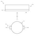
도 1은 모션 의존 디스플레이를 위한 시스템(100)의 개략도이다. 시스템(100)은 제1 헤드폰 디바이스(104a) 및 제2 헤드폰 디바이스(104b)를 갖는 헤드폰(102)(예를 들어, 헤드폰 세트)을 포함한다. 시스템(100)은 또한 디스플레이 스크린(108)을 포함하는 외부 디바이스(106)를 포함한다.FIG. 1 is a schematic diagram of a system (100) for a motion dependent display. The system (100) includes headphones (102) (e.g., a set of headphones) having a first headphone device (104a) and a second headphone device (104b). The system (100) also includes an external device (106) including a display screen (108).
헤드폰(102) 및 외부 디바이스(106)는 물리적 환경 또는 주변 환경으로 지칭될 수 있는 환경(110) 내에서 서로 가까이 위치된다. 헤드폰은 환경(110) 내에 위치된 사용자(112)가 착용하고 있다. 사용자(112)는 외부 디바이스(106)의 디스플레이 스크린(108)을 볼 수 있다. 예시된 구현예에서, 사용자(112)는 디스플레이 스크린(108)에 대한 사용자(112)의 머리의 위치 및 배향에 따라 변하는 시야각(114)에 따라 디스플레이 스크린(108)을 보고 있다.The headphones (102) and the external device (106) are positioned in proximity to each other within an environment (110), which may be referred to as a physical environment or ambient environment. The headphones are worn by a user (112) positioned within the environment (110). The user (112) can view a display screen (108) of the external device (106). In the illustrated implementation, the user (112) views the display screen (108) through a field of view (114) that varies depending on the position and orientation of the user's (112) head relative to the display screen (108).
제1 헤드폰 디바이스(104a) 및 제2 헤드폰 디바이스(104b)는 물리적으로 독립적인 무선 헤드폰 디바이스들일 수 있으며, 예를 들어, 사용자가 그의 귀에 인접하게, 예를 들어, 제1 헤드폰 디바이스(104a) 및 제2 헤드폰 디바이스(104b) 각각의 결합에 의해, 착용하도록 구성된 무선 이어버드(earbud)들로서 구현될 수 있다.The first headphone device (104a) and the second headphone device (104b) may be physically independent wireless headphone devices, and may be implemented as wireless earbuds configured to be worn by a user adjacent to his or her ears, for example, by coupling the first headphone device (104a) and the second headphone device (104b), respectively.
외부 디바이스(106)는 디스플레이 스크린(108)을 사용하여 사용자(112)에게 콘텐츠를 제시하도록 구성된다. 사용자(112)에게 제시되는 콘텐츠는 외부 디바이스(106)에 의해 생성될 수 있다. 외부 디바이스(106)는 제1 헤드폰 디바이스(104a) 및 제2 헤드폰 디바이스(104b)의 모션에 의존하여 시각적 콘텐츠를 생성하도록 구성될 수 있다. 외부 디바이스에 의해 생성되는 시각적 콘텐츠는 3차원 장면의 렌더링일 수 있다. 외부 디바이스(106)는 추가로, 예컨대, 시각적 콘텐츠를 외부 디바이스(106)의 디스플레이 스크린(108)에 출력함으로써, 시각적 콘텐츠를 사용자(112)에게 제시하도록 구성된다. 제1 헤드폰 디바이스(104a) 및 제2 헤드폰 디바이스(104b)의 모션에 의존하여 시각적 콘텐츠를 생성하는 일례로서, 3차원 장면의 렌더링은, 제1 헤드폰 디바이스(104a) 및 제2 헤드폰 디바이스(104b)의 모션을 설명하는 제1 헤드폰 디바이스(104a) 및 제2 헤드폰 디바이스(104b)로부터의 정보를 사용하여 추정되는 바와 같이, 사용자(112)의 머리의 위치 및 배향의 변화에 따라 수정될 수 있다. 외부 디바이스(106)에 의한 시각적 콘텐츠의 생성은 본 명세서에서 추가로 설명될 것이다.The external device (106) is configured to present content to the user (112) using the display screen (108). The content presented to the user (112) may be generated by the external device (106). The external device (106) may be configured to generate visual content based on the motion of the first headphone device (104a) and the second headphone device (104b). The visual content generated by the external device may be a rendering of a three-dimensional scene. The external device (106) is further configured to present the visual content to the user (112), for example, by outputting the visual content to the display screen (108) of the external device (106). As an example of generating visual content dependent on the motion of the first headphone device (104a) and the second headphone device (104b), the rendering of the three-dimensional scene can be modified in response to changes in the position and orientation of the user's (112) head, as estimated using information from the first headphone device (104a) and the second headphone device (104b) that describes the motion of the first headphone device (104a) and the second headphone device (104b). The generation of visual content by the external device (106) will be further described herein.
도 2는 제1 헤드폰 디바이스(104a), 제2 헤드폰 디바이스(104b), 및 외부 디바이스(106)에 대한 예시적인 하드웨어 구성을 도시하는 블록도이다. 설명되는 바와 같이, 제1 헤드폰 디바이스(104a), 제2 헤드폰 디바이스(104b), 및 외부 디바이스(106)는 모두 독립적인 입력 디바이스들, 출력 디바이스들, 센서들, 및/또는 컴퓨팅 디바이스들을 포함할 수 있다. 또한, 제1 헤드폰 디바이스(104a), 제2 헤드폰 디바이스(104b), 및 외부 디바이스(106) 각각은 그들이 서로에 대해 무선으로 신호들을 송신하게 하는 통신 능력들을 포함한다. 이는, 예를 들어, 제1 헤드폰 디바이스(104a) 및 제2 헤드폰 디바이스(104b)를 사용하여 외부 디바이스(106)에 의해 제공되는 오디오의 재생뿐만 아니라, 제1 헤드폰 디바이스(104a) 및 제2 헤드폰 디바이스(104b)에서 생성된 센서 신호들 또는 입력 신호들에 기초한 외부 디바이스의 하나 이상의 기능들의 제어를 허용한다.FIG. 2 is a block diagram illustrating an exemplary hardware configuration for a first headphone device (104a), a second headphone device (104b), and an external device (106). As described, the first headphone device (104a), the second headphone device (104b), and the external device (106) may all include independent input devices, output devices, sensors, and/or computing devices. Additionally, the first headphone device (104a), the second headphone device (104b), and the external device (106) each include communication capabilities that allow them to wirelessly transmit signals to one another. This allows, for example, playback of audio provided by the external device (106) using the first headphone device (104a) and the second headphone device (104b), as well as control of one or more functions of the external device based on sensor signals or input signals generated by the first headphone device (104a) and the second headphone device (104b).
제1 헤드폰 디바이스(104a)는 하우징(220a), 오디오 출력 디바이스(221a), 통신 디바이스(222a), 컴퓨팅 디바이스(223a), 센서들(224a), 및 재충전가능 배터리와 같은 전원(225a)을 포함할 수 있다. 제1 헤드폰 디바이스(104a)에는 다른 컴포넌트들이 포함될 수 있다.The first headphone device (104a) may include a housing (220a), an audio output device (221a), a communication device (222a), a computing device (223a), sensors (224a), and a power source (225a), such as a rechargeable battery. The first headphone device (104a) may include other components.
제1 헤드폰 디바이스(104a)의 하우징(220a)은 제1 헤드폰 디바이스(104a)의 컴포넌트들을 물리적으로 상호연결하고/하거나 둘러싸도록 구성된 물리적 구조이다. 하우징(220a)은 그것이 사용자(112)의 귀에 대해 대체로 고정된 위치에 단단히 보유되게 하는 기하학적 구성을 가질 수 있다. 오디오 출력 디바이스(221a)(예컨대, 하나 이상의 오디오 출력 디바이스들)는, 예를 들어, 외부 디바이스(106)로부터, 수신된 신호에 응답하여 소리를 생성하도록 구성된다. 오디오 출력 디바이스(221a)는 종래 스피커의 형태로 또는 다른 적합한 구성에 따라 구현될 수 있다. 오디오 출력 디바이스(221a)는 오디오 출력 디바이스(221a)에서 생성되는 소리를 사용자(112)가 들을 수 있도록 사용자(112)의 귀 근처에 오디오 출력 디바이스(221a)를 위치시키는 방식으로 하우징(220a)에 결합된다. 통신 디바이스(222a)는 제2 헤드폰 디바이스(104b) 및 외부 디바이스(106)와 같은 다른 디바이스들과의 유선 또는 무선 통신을 지원한다. 통신 디바이스(222a)는 단거리 및/또는 장거리 통신을 지원할 수 있다. 임의의 적합한 유선 또는 무선 통신 프로토콜이 사용될 수 있다.A housing (220a) of the first headphone device (104a) is a physical structure configured to physically interconnect and/or enclose the components of the first headphone device (104a). The housing (220a) may have a geometric configuration such that it is held firmly in a generally fixed position relative to the ear of the user (112). An audio output device (221a) (e.g., one or more audio output devices) is configured to generate sound in response to a signal received, for example, from an external device (106). The audio output device (221a) may be implemented in the form of a conventional speaker or according to another suitable configuration. The audio output device (221a) is coupled to the housing (220a) in such a way that the audio output device (221a) is positioned near the ear of the user (112) such that sound generated by the audio output device (221a) can be heard by the user (112). The communication device (222a) supports wired or wireless communication with other devices, such as the second headphone device (104b) and the external device (106). The communication device (222a) may support short-range and/or long-range communication. Any suitable wired or wireless communication protocol may be used.
컴퓨팅 디바이스(223a)는 제1 헤드폰 디바이스(104a)의 동작을 제어하도록 구성되는 종래의 컴퓨팅 디바이스이다. 제1 헤드폰 디바이스(104a)의 컴퓨팅 디바이스(223a)는 도 8의 컴퓨팅 디바이스(880) 또는 다른 적합한 컴퓨팅 디바이스를 사용하여 구현될 수 있다. 컴퓨팅 디바이스(223a)는, 제1 헤드폰 디바이스(104a)의 전원 켜기, 제1 헤드폰 디바이스(104a)의 전원 끄기, 제1 헤드폰 디바이스(104a), 제2 헤드폰 디바이스(104b) 및 외부 디바이스(106) 사이의 통신들(예컨대, 페어링을 포함함)을 확립하는 것, 통신 디바이스(222a)를 사용하여 외부 디바이스(106)로부터 오디오 신호를 수신하는 것, 외부 디바이스(106)로부터의 오디오 신호를 디코딩하는 것, 오디오 신호(예컨대, 디코딩된 오디오 신호)를 오디오 출력 디바이스(221a)로 출력하는 것, 및 센서들(224a)로부터 외부 디바이스(106)로 센서 신호들을 송신하는 것과 같은 제1 헤드폰 디바이스(104a)의 기능들을 구현하도록 구성된다. 제1 헤드폰 디바이스(104a)의 이들 기능들 및 다른 기능들은, 컴퓨팅 디바이스(223a)에 이용가능하고 실행될 때, 기능들과 연관된 컴퓨팅 프로세스들의 실행을 야기하는 컴퓨터 프로그램 명령어들을 사용하여 구현될 수 있다.The computing device (223a) is a conventional computing device configured to control the operation of the first headphone device (104a). The computing device (223a) of the first headphone device (104a) may be implemented using the computing device (880) of FIG. 8 or another suitable computing device. The computing device (223a) is configured to implement functions of the first headphone device (104a), such as powering on the first headphone device (104a), powering off the first headphone device (104a), establishing communications (e.g., including pairing) between the first headphone device (104a), the second headphone device (104b), and the external device (106), receiving an audio signal from the external device (106) using the communication device (222a), decoding the audio signal from the external device (106), outputting the audio signal (e.g., the decoded audio signal) to the audio output device (221a), and transmitting sensor signals from the sensors (224a) to the external device (106). These and other functions of the first headphone device (104a) may be implemented using computer program instructions that, when available and executed on the computing device (223a), cause execution of computing processes associated with the functions.
센서들(224a)은 제1 가속도 센서(226a), 하나 이상의 자이로스코프들(227a), 및 하나 이상의 자력계들(228a)을 포함할 수 있다. 일례로서, 제1 가속도 센서(226a), 하나 이상의 자이로스코프들(227a), 및 하나 이상의 자력계들(228a)은 종래의 관성 측정 유닛에 포함될 수 있다.The sensors (224a) may include a first acceleration sensor (226a), one or more gyroscopes (227a), and one or more magnetometers (228a). As an example, the first acceleration sensor (226a), one or more gyroscopes (227a), and one or more magnetometers (228a) may be included in a conventional inertial measurement unit.
제2 헤드폰 디바이스(104b)는 제1 헤드폰 디바이스(104a)와 동등하고, 제1 헤드폰 디바이스(104a)에 대해 설명된 구성을 이용할 수 있다. 따라서, 제2 헤드폰 디바이스는 하우징(220a)과 동등한 하우징(220b), 오디오 출력 디바이스(221a)와 동등한 오디오 출력 디바이스(221b), 통신 디바이스(222a)와 동등한 통신 디바이스(222b), 컴퓨팅 디바이스(223a)와 동등한 컴퓨팅 디바이스(223b), 센서들(224a)과 동등한 센서들(224b), 및 재충전가능 배터리와 같은 전원(225b)을 포함할 수 있다. 센서들(224b)은 센서들(224a)의 컴포넌트들과 동등한, 제2 가속도 센서(226b), 하나 이상의 자이로스코프들(227b) 및 하나 이상의 자력계들(228b)을 포함할 수 있다. 제2 가속도 센서(226b)는 하나 이상의 선형 자유도들 및/또는 하나 이상의 회전 자유도들로 제2 헤드폰 디바이스(104b)의 가속도를 묘사하는 제2 가속도 신호를 출력하도록 구성된다. 일례로서, 제2 가속도 신호는 (예컨대, XYZ 좌표계에서의 가속도에 대응하는) 3개의 선형 자유도들로 제2 헤드폰 디바이스(104b)의 가속도를 묘사하는 정보를 포함할 수 있다.The second headphone device (104b) is equivalent to the first headphone device (104a) and can utilize the configuration described for the first headphone device (104a). Accordingly, the second headphone device can include a housing (220b) equivalent to the housing (220a), an audio output device (221b) equivalent to the audio output device (221a), a communication device (222b) equivalent to the communication device (222a), a computing device (223b) equivalent to the computing device (223a), sensors (224b) equivalent to the sensors (224a), and a power source (225b) such as a rechargeable battery. The sensors (224b) can include a second acceleration sensor (226b), one or more gyroscopes (227b), and one or more magnetometers (228b), which are equivalent to the components of the sensors (224a). The second acceleration sensor (226b) is configured to output a second acceleration signal describing the acceleration of the second headphone device (104b) in one or more linear degrees of freedom and/or one or more rotational degrees of freedom. As an example, the second acceleration signal may include information describing the acceleration of the second headphone device (104b) in three linear degrees of freedom (e.g., corresponding to acceleration in an XYZ coordinate system).
외부 디바이스(106)는 디스플레이 스크린(108), 컴퓨팅 디바이스(230), 이미징 디바이스(231), 3차원 감지 디바이스(232), 및 통신 디바이스(233)를 포함할 수 있다. 컴퓨팅 디바이스(230)는, 시각적 콘텐츠를 렌더링하는 것, 시각적 콘텐츠를 디스플레이 스크린(108)에 출력하는 것, 이미징 디바이스(231)로부터 이미지들을 획득하는 것, 통신 디바이스(233)를 사용하여 헤드폰(102)에 정보를 전송 및 수신하는 것과 같은 외부 디바이스(106)의 컴퓨팅 기능들을 구현한다. 컴퓨팅 디바이스(230)는 도 8의 컴퓨팅 디바이스(880) 또는 다른 적합한 컴퓨팅 디바이스를 사용하여 구현될 수 있다. 이미징 디바이스(231)는, 예들로서, 하나 이상의 가시 및/또는 적외선 스펙트럼 비디오 카메라들 또는 스틸 카메라들을 포함할 수 있다. 3차원 감지 디바이스(232)는, 예들로서, 하나 이상의 라이다, 레이더, 초음파, 깊이 카메라들, 및/또는 구조화된 조명 디바이스들을 포함할 수 있다. 통신 디바이스는 제1 헤드폰 디바이스(104a) 및 제2 헤드폰 디바이스(104b)와 통신하도록 구성되고, 제1 헤드폰 디바이스(104a)의 통신 디바이스(222a)에 대해 설명된 방식으로 구현될 수 있다.The external device (106) may include a display screen (108), a computing device (230), an imaging device (231), a 3D sensing device (232), and a communication device (233). The computing device (230) implements computing functions of the external device (106), such as rendering visual content, outputting the visual content to the display screen (108), obtaining images from the imaging device (231), and transmitting and receiving information to the headphones (102) using the communication device (233). The computing device (230) may be implemented using the computing device (880) of FIG. 8 or another suitable computing device. The imaging device (231) may include, for example, one or more visible and/or infrared spectrum video cameras or still cameras. The 3D sensing device (232) may include, for example, one or more lidar, radar, ultrasound, depth cameras, and/or structured illumination devices. The communication device is configured to communicate with the first headphone device (104a) and the second headphone device (104b) and may be implemented in the manner described for the communication device (222a) of the first headphone device (104a).
도 3은 모션 의존 디스플레이를 위한 시스템(100)의 동작의 블록도이다. 시스템(100)은 제1 가속도 신호(340a) 및 제2 가속도 신호(340b)를 입력들로서 이용한다. 머리 포즈 추정(342)은 제1 가속도 신호(340a) 및 제2 가속도 신호(340b)에 기초하여 결정되고, 3차원 장면(344)에 적용되어 3차원 장면(344)에 대한 수정(346)을 결정한다. 수정(346)의 적용에 후속하여, 렌더러(348)는 3차원 장면(344)을 프로세싱하여 출력(349)을 생성한다. 출력(349)은, 3차원 장면(344)에 기초하여 생성되고 종래의 렌더링 기법들을 사용하여 생성될 수 있는, 이미지(예컨대, 프레임들의 시퀀스로부터의 프레임일 수 있는 2차원 디지털 이미지) 또는 다수의 이미지들과 같은 시각적 콘텐츠이다. 출력(349)은, 예를 들어, 출력(349)이 디스플레이 스크린(108) 또는 다른 적합한 디스플레이 디바이스에 의해 사용자(112)에게 디스플레이되게 하는 신호를 제공함으로써, 사용자(112)에게 제시될 수 있다.FIG. 3 is a block diagram of the operation of a system (100) for a motion dependent display. The system (100) uses a first acceleration signal (340a) and a second acceleration signal (340b) as inputs. A head pose estimation (342) is determined based on the first acceleration signal (340a) and the second acceleration signal (340b) and is applied to a three-dimensional scene (344) to determine a correction (346) to the three-dimensional scene (344). Following the application of the correction (346), a renderer (348) processes the three-dimensional scene (344) to generate an output (349). The output (349) is visual content, such as an image (e.g., a two-dimensional digital image, which may be a frame from a sequence of frames) or multiple images, generated based on the three-dimensional scene (344) and which may be generated using conventional rendering techniques. The output (349) may be presented to the user (112), for example, by providing a signal causing the output (349) to be displayed to the user (112) by a display screen (108) or other suitable display device.
제1 가속도 신호(340a)는 제1 헤드폰 디바이스(104a)의 제1 가속도 센서(226a)에 의해 출력되고, 제2 가속도 신호(340b)는 제2 헤드폰 디바이스(104b)의 제2 가속도 센서(226b)에 의해 출력된다. 제1 가속도 센서(226a)에 의해 출력되는 제1 가속도 신호(340a)는 하나 이상의 선형 자유도들 및/또는 하나 이상의 회전 자유도들로 제1 헤드폰 디바이스(104a)의 가속도를 묘사하고, 제2 가속도 센서(226b)에 의해 출력되는 제2 가속도 신호(340b)는 하나 이상의 선형 자유도들 및/또는 하나 이상의 회전 자유도들로 제2 헤드폰 디바이스(104b)의 가속도를 묘사한다.A first acceleration signal (340a) is output by a first acceleration sensor (226a) of the first headphone device (104a), and a second acceleration signal (340b) is output by a second acceleration sensor (226b) of the second headphone device (104b). The first acceleration signal (340a) output by the first acceleration sensor (226a) describes an acceleration of the first headphone device (104a) with one or more linear degrees of freedom and/or one or more rotational degrees of freedom, and the second acceleration signal (340b) output by the second acceleration sensor (226b) describes an acceleration of the second headphone device (104b) with one or more linear degrees of freedom and/or one or more rotational degrees of freedom.
제1 가속도 신호(340a) 및 제2 가속도 신호(340b)는 3개의 선형 자유도들로 각각 제1 헤드폰 디바이스(104a) 및 제2 헤드폰 디바이스(104b)의 선형 가속도를 묘사하는 정보를 포함할 수 있다. 참고의 편의상, 3개의 선형 자유도들은 종방향(X), 측방향(Y) 및 높이 방향(Z)을 갖는 XYZ 좌표계에 대응하는 것으로 설명될 수 있다. 각각 제1 가속도 센서(226a) 및 제2 가속도 센서(226b)의 위치에 대해 참조되거나 각각 제1 헤드폰 디바이스(104a) 또는 제2 헤드폰 디바이스(104b)의 다른 부분에 대해 참조되는 별개의 좌표계가 제1 헤드폰 디바이스(104a) 및 제2 헤드폰 디바이스(104b) 각각에 대해 사용될 수 있다. 따라서, 제1 가속도 신호(340a) 및 제2 가속도 신호(340b)는 각각 종방향(X)으로의 선형 가속도, 측방향(Y)으로의 선형 가속도, 및 높이 방향(Z)으로의 선형 가속도를 묘사할 수 있다.The first acceleration signal (340a) and the second acceleration signal (340b) may include information describing the linear acceleration of the first headphone device (104a) and the second headphone device (104b), respectively, in three linear degrees of freedom. For convenience of reference, the three linear degrees of freedom may be described as corresponding to an XYZ coordinate system having a longitudinal (X), a lateral (Y) and an elevation (Z) direction. A separate coordinate system may be used for each of the first headphone device (104a) and the second headphone device (104b), respectively, referenced with respect to the positions of the first acceleration sensor (226a) and the second acceleration sensor (226b), respectively, or referenced with respect to other portions of the first headphone device (104a) or the second headphone device (104b), respectively. Accordingly, the first acceleration signal (340a) and the second acceleration signal (340b) can describe linear acceleration in the longitudinal direction (X), linear acceleration in the lateral direction (Y), and linear acceleration in the height direction (Z), respectively.
일부 구현예들에서, 제1 가속도 신호(340a) 및 제2 가속도 신호(340b)는, 또한, 하나 이상의 회전 자유도들로 각각 제1 헤드폰 디바이스(104a) 및 제2 헤드폰 디바이스(104b)의 회전 가속도들을 묘사하는 정보를 포함할 수 있다. 일례로서, 제1 가속도 신호(340a) 및 제2 가속도 신호(340b) 각각은 종방향(X)으로 연장되는 축을 중심으로 하는 롤 가속도, 측방향(Y)으로 연장되는 피치 축을 중심으로 하는 피치 가속도, 및 높이 방향(Z)으로 연장되는 축을 중심으로 하는 요 가속도를 묘사할 수 있다. 신호들은, 각각 제1 가속도 센서(226a) 및 제2 가속도 센서(226b) 각각을 통해 연장되는 각자의 피치 축, 롤 축 및 요 축과 같은, 제1 헤드폰 디바이스(104a) 및 제2 헤드폰 디바이스(104b) 각각에 특정한 축들에 대해 참조될 수 있다.In some implementations, the first acceleration signal (340a) and the second acceleration signal (340b) may also include information describing rotational accelerations of the first headphone device (104a) and the second headphone device (104b), respectively, in one or more rotational degrees of freedom. As an example, the first acceleration signal (340a) and the second acceleration signal (340b) may each describe a roll acceleration about an axis extending in the longitudinal (X) direction, a pitch acceleration about a pitch axis extending in the lateral (Y) direction, and a yaw acceleration about an axis extending in the height (Z) direction. The signals may be referenced to axes specific to each of the first headphone device (104a) and the second headphone device (104b), such as a pitch axis, a roll axis, and a yaw axis extending through each of the first acceleration sensor (226a) and the second acceleration sensor (226b), respectively.
머리 포즈 추정(342)은 제1 가속도 신호(340a) 및 제2 가속도 신호(340b)에 기초한, 디스플레이 스크린(108)에 대한 사용자(112)의 머리 배향(예컨대, 시야각(114)에 의해 표현됨)의 추정의 결정이다. 머리 포즈 추정(342)은, 또한, 디스플레이 스크린(108)에 대한 사용자(112)의 머리의 (예컨대, 선형 좌표계에 대한) 위치의 추정을 포함할 수 있다.Head pose estimation (342) is a determination of an estimate of an orientation of the user's (112) head (e.g., represented by a field of view (114)) relative to the display screen (108) based on the first acceleration signal (340a) and the second acceleration signal (340b). Head pose estimation (342) may also include an estimation of a position (e.g., relative to a linear coordinate system) of the user's (112) head relative to the display screen (108).
머리 포즈 추정(342)은 제1 헤드폰 디바이스(104a), 제2 헤드폰 디바이스(104b) 및 사용자(112)의 머리의 상대 위치들을 가정함으로써 결정될 수 있다. 제1 헤드폰 디바이스(104a) 및 제2 헤드폰 디바이스(104b)는, 예를 들어, 제1 헤드폰 디바이스(104a)가 사용자의 왼쪽 귀에 인접하게 위치된 상태로, 그리고 제2 헤드폰 디바이스(104b)가 사용자의 오른쪽 귀에 인접한 상태로, 사용자(112)에 의해 착용되는 것으로 가정된다. 그 결과, 제1 헤드폰 디바이스(104a) 및 제2 헤드폰 디바이스(104b)의 위치들은 사용자의 머리에 대해 고정된 것으로 그리고 따라서 서로에 대해 고정된 상대 위치에 있는 것으로 가정된다. 일례로서, 제1 헤드폰 디바이스(104a)와 제2 헤드폰 디바이스(104b) 사이의 거리는 미리결정된 가정된 값, 측정된 값, 사용자 입력에 의해 제공되는 값 등일 수 있다.Head pose estimation (342) can be determined by assuming relative positions of the first headphone device (104a), the second headphone device (104b), and the user's (112) head. The first headphone device (104a) and the second headphone device (104b) are assumed to be worn by the user (112), for example, with the first headphone device (104a) positioned adjacent to the user's left ear, and the second headphone device (104b) positioned adjacent to the user's right ear. As a result, the positions of the first headphone device (104a) and the second headphone device (104b) are assumed to be fixed with respect to the user's head and thus at fixed relative positions with respect to each other. As an example, the distance between the first headphone device (104a) and the second headphone device (104b) can be a predetermined assumed value, a measured value, a value provided by a user input, etc.
제1 헤드폰 디바이스(104a) 및 제2 헤드폰 디바이스(104b)에 대한 상대 위치들을 가정함으로써, 사용자(112)의 머리의 이동은 제1 헤드폰 디바이스(104a) 및 제2 헤드폰 디바이스(104b)의 위치들(예컨대, 위치들은 제1 가속도 센서(226a) 및 제2 가속도 센서(226b)의 위치들에 의해 표현됨)을 강체 상의 지점들로서 모델링함으로써 추정될 수 있다. 추적이 시작될 때, 외부 디바이스(106)의 디스플레이 스크린(108)에 대한 제1 헤드폰 디바이스(104a) 및 제2 헤드폰 디바이스(104b)의 초기 위치들이 설정된다. 초기 위치들은 시야각(114)이 디스플레이 스크린(108)의 중심으로 지향되는 것에 대응한다. 일례로서, 초기 위치들을 캘리브레이션하기 위해, 추적이 시작될 때 사용자(112)는 디스플레이 스크린(108)을 직접 보도록 (예컨대, 외부 디바이스(106)에 의해 출력되는 시각적 프롬프트 또는 가청 프롬프트에 의해) 지시될 수 있고, 초기 위치들은, 예를 들어 사용자(112)가 시야각(114)이 중심설정됨을 나타내는 버튼을 누를 때 디스플레이 스크린(108)의 중심에 대응하도록 시야각(114)을 재설정함으로써, 시스템(100)의 사용 동안 업데이트될 수 있다. 디스플레이 스크린(108)에 대한 시야각(114)의 추적 동안, 제1 가속도 신호(340a) 및 제2 가속도 신호(340b)는 제1 헤드폰 디바이스(104a) 및 제2 헤드폰 디바이스(104b) 각각의 속도 및 위치를 반복적으로 업데이트하는 데 사용되며, 이는 시야각(114)의 추정의 계산을 허용한다.By assuming relative positions of the first headphone device (104a) and the second headphone device (104b), the movement of the user's (112) head can be estimated by modeling the positions of the first headphone device (104a) and the second headphone device (104b) (e.g., the positions are represented by the positions of the first acceleration sensor (226a) and the second acceleration sensor (226b)) as points on a rigid body. When tracking is initiated, initial positions of the first headphone device (104a) and the second headphone device (104b) with respect to the display screen (108) of the external device (106) are set. The initial positions correspond to the field of view (114) being oriented toward the center of the display screen (108). As an example, to calibrate the initial positions, the user (112) may be instructed (e.g., by a visual prompt or audible prompt output by the external device (106)) to look directly at the display screen (108) when tracking is initiated, and the initial positions may be updated during use of the system (100), for example, by resetting the field of view (114) to correspond to the center of the display screen (108) when the user (112) presses a button indicating that the field of view (114) is centered. During tracking of the field of view (114) relative to the display screen (108), the first acceleration signal (340a) and the second acceleration signal (340b) are used to repeatedly update the velocity and position of the first headphone device (104a) and the second headphone device (104b), respectively, which allows for computation of an estimate of the field of view (114).
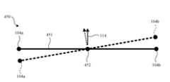
개략적인 톱-다운 뷰(top-down view)인 예시된 구현예에서, 기하학적 모델(450)은 사용자(112)의 머리의 모션 및 사용자(112)의 시야각(114)을 추정하는 데 사용된다. 기하학적 모델(450)에서, 사용자(112)의 머리는 제1 헤드폰 디바이스(104a)와 제2 헤드폰 디바이스(104b) 사이에 위치되는 요 회전 중심(452)을 갖는 강성 빔(451)으로서 모델링된다. 일정 기간의 시작 시의 강성 빔(451)의 초기 위치는 실선으로서 표시되고, 기간의 종료 시의 강성 빔(451)의 최종 위치는 파선으로서 표시된다.In the illustrated implementation, which is a schematic top-down view, a geometric model (450) is used to estimate the motion of the user's (112) head and the field of view (114) of the user's (112). In the geometric model (450), the user's (112) head is modeled as a rigid beam (451) having a center of yaw rotation (452) positioned between the first headphone device (104a) and the second headphone device (104b). The initial position of the rigid beam (451) at the start of a period is represented by a solid line, and the final position of the rigid beam (451) at the end of the period is represented by a dashed line.
기간의 시작 시에, 제1 헤드폰 디바이스(104a)는 초기 위치에 위치되고 초기 속도 v_1i를 가지며, 제2 헤드폰 디바이스(104b)는 초기 위치에 위치되고 초기 속도 v_2i를 갖는다. 기간 동안, 제1 헤드폰 디바이스(104a)의 가속도 a_1이 제1 가속도 신호(340a)에 기초하여, 예를 들어, 기간 동안의 제1 가속도 신호(340a)의 평균 값으로서 결정된다. 유사하게, 기간 동안, 제2 헤드폰 디바이스(104b)의 가속도 a_2가 제2 가속도 신호(340b)에 기초하여, 예를 들어, 기간 동안의 제2 가속도 신호(340b)의 평균 값으로서 결정된다.At the start of the period, the first headphone device (104a) is positioned at an initial position and has an initial velocity v_1i, and the second headphone device (104b) is positioned at an initial position and has an initial velocity v_2i. During the period, an acceleration a_1 of the first headphone device (104a) is determined based on the first acceleration signal (340a), for example, as an average value of the first acceleration signal (340a) during the period. Similarly, during the period, an acceleration a_2 of the second headphone device (104b) is determined based on the second acceleration signal (340b), for example, as an average value of the second acceleration signal (340b) during the period.
표준 운동 방정식들을 사용하여, 기간의 종료 시의 제1 헤드폰 디바이스(104a)의 위치 및 기간의 종료 시의 제1 헤드폰 디바이스(104a)의 최종 속도 v1_f는 제1 헤드폰 디바이스(104a)의 초기 위치, 제1 헤드폰 디바이스(104a)의 초기 속도 v_1i, 기간 동안의 제1 헤드폰 디바이스(104a)의 가속도 a_1, 및 기간의 지속시간에 기초하여 결정된다. 유사하게, 기간의 종료 시의 제2 헤드폰 디바이스(104b)의 위치 및 기간의 종료 시의 제2 헤드폰 디바이스(104b)의 최종 속도 v2_f는 제2 헤드폰 디바이스(104b)의 초기 위치, 제2 헤드폰 디바이스(104b)의 초기 속도 v_2i, 기간 동안의 제2 헤드폰 디바이스(104b)의 가속도 a_1, 및 기간의 지속시간에 기초하여 결정된다.Using standard equations of motion, the position of the first headphone device (104a) at the end of the period and the final velocity v1_f of the first headphone device (104a) at the end of the period are determined based on the initial position of the first headphone device (104a), the initial velocity v_1i of the first headphone device (104a), the acceleration a_1 of the first headphone device (104a) during the period, and the duration of the period. Similarly, the position of the second headphone device (104b) at the end of the period and the final velocity v2_f of the second headphone device (104b) at the end of the period are determined based on the initial position of the second headphone device (104b), the initial velocity v_2i of the second headphone device (104b), the acceleration a_1 of the second headphone device (104b) during the period, and the duration of the period.
제1 헤드폰 디바이스(104a) 및 제2 헤드폰 디바이스(104b)에 대한 최종 위치들은 기간의 종료 시의 강성 빔(451) 및 그의 요 회전 중심(452)에 대한 업데이트된 위치를 결정하는 데 사용된다. 시야각(114)은, 제1 헤드폰 디바이스(104a) 및 제2 헤드폰 디바이스(104b)의 최종 위치들에 기초하여 결정되는 강성 빔(451)의 각도에 의해 주어진다. 이는 이러한 추정에서 제1 헤드폰 디바이스(104a), 제2 헤드폰 디바이스(104b) 및 요 회전 중심(452)의 위치들이 서로에 대해 고정된 것으로 가정되기 때문에 간단한 기하학적 구성이다.The final positions for the first headphone device (104a) and the second headphone device (104b) are used to determine an updated position for the rigid beam (451) and its center of yaw rotation (452) at the end of the period. The field of view (114) is given by the angle of the rigid beam (451) which is determined based on the final positions of the first headphone device (104a) and the second headphone device (104b). This is a simple geometrical configuration since the positions of the first headphone device (104a), the second headphone device (104b) and the center of yaw rotation (452) are assumed to be fixed with respect to each other in this estimation.
위에서 설명된 이러한 추정 프로세스는 요 회전 축에 대한 머리 포즈 추정(342)에 대한 업데이트를 가져온다. 일부 구현예들에서, (예컨대, 종방향(X) 및 측방향(Y)으로의) 머리의 위치는 위에서 설명된 추정에 반영된 바와 같이 요 회전 중심(452)의 위치의 변화에 따라 업데이트될 수 있다. 다른 구현예들에서, 사용자의 머리의 병진 위치는 고정된 것으로 가정되고, 요 회전 중심(452)의 위치는 업데이트되지 않는다.The estimation process described above results in an update to the head pose estimate (342) with respect to the yaw rotation axis. In some implementations, the position of the head (e.g., in the longitudinal (X) and lateral (Y) directions) may be updated as the location of the yaw rotation center (452) changes, as reflected in the estimation described above. In other implementations, the translational position of the user's head is assumed to be fixed, and the location of the yaw rotation center (452) is not updated.
위의 설명은 설명의 편의를 위해 요 회전의 추정과 관련하여 이루어지지만, 프로세스는 다른 자유도들을 고려하도록 확장되어, 그에 의해 피치 회전 축 및 요 회전 축에 대한 머리 포즈 추정(342)에 대한 업데이트들을 생성할 수 있다. 사용자의 머리의 위치의 추정된 변화는, 또한, 피치 축, 롤 축 및 요 축에 대한 회전 중심들의 위치의 추정된 변화들에 따라 결정되고 추적될 수 있다. 따라서, 추정되고 머리 포즈 추정(342)에 포함되는 사용자(112)의 머리 배향은 피치 값, 롤 값, 및 요 값을 포함할 수 있다. 추가로, 위에서 설명된 추정은 사용자(112)의 머리를 제1 헤드폰 디바이스(104a)와 제2 헤드폰 디바이스(104b) 사이에서 연장되는 빔으로서 기하학적으로 모델링하지만, 추정은 사용자의 머리를 상이한 방식으로 모델링함으로써, 예를 들어, 사용자(112)의 머리를 제1 헤드폰 디바이스(104a) 및 제2 헤드폰 디바이스(104b)의 피치 축 및 요 축이 연장되는 평면으로서 모델링함으로써, 또는 사용자(112)의 머리를 전형적인 인간의 머리의 이동을 모방하는 관절 구조를 갖는 3차원 시스템으로서 모델링함으로써 수행될 수 있다.While the above description is made with respect to estimation of yaw rotation for convenience of explanation, the process can be extended to consider other degrees of freedom, thereby generating updates to the head pose estimation (342) about the pitch and yaw axes. The estimated change in the position of the user's head can also be determined and tracked based on the estimated changes in the positions of the rotation centers about the pitch, roll and yaw axes. Accordingly, the head orientation of the user (112) that is estimated and included in the head pose estimation (342) can include pitch values, roll values, and yaw values. Additionally, while the estimation described above geometrically models the user's (112) head as a beam extending between the first headphone device (104a) and the second headphone device (104b), the estimation can be performed by modeling the user's (112) head in different ways, for example, by modeling the user's (112) head as a plane extending through the pitch and yaw axes of the first headphone device (104a) and the second headphone device (104b), or by modeling the user's (112) head as a three-dimensional system having joint structures that mimic the movements of a typical human head.
일부 구현예들에서, 디스플레이 스크린(108)에 대한 머리 포즈 추정(342)을 결정하는 것은 제1 헤드폰 디바이스(104a) 및 제2 헤드폰 디바이스(104b)에 대한 디스플레이 스크린(108)의 추적 모션을 결정하는 것을 추가로 포함한다. 일례로서, 디스플레이 스크린(108)을 통합하는 외부 디바이스(106)는 이동가능할 수 있다. 일례로서, 외부 디바이스(106)는 사용자(112)에 의해 보유될 수 있는 핸드헬드 디바이스일 수 있다. 디스플레이 스크린(108)의 이동을 추적하기 위해, 외부 디바이스는 하나 이상의 가속도계들과 같은, 제1 헤드폰 디바이스(104a) 및 제2 헤드폰 디바이스(104b)에 대해 설명된 것들과 동등한 센서들을 포함할 수 있으며, 이는 제1 헤드폰 디바이스(104a) 및 제2 헤드폰 디바이스(104b)에 대해 설명된 방식으로, 또는 다른 적합한 방식으로 외부 디바이스(106) 및 디스플레이 스크린(108)의 위치의 변화들을 추정하는 데 사용될 수 있다.In some implementations, determining a head pose estimation (342) for the display screen (108) further includes determining a tracking motion of the display screen (108) relative to the first headphone device (104a) and the second headphone device (104b). As an example, the external device (106) incorporating the display screen (108) may be movable. As an example, the external device (106) may be a handheld device that may be held by the user (112). To track the movement of the display screen (108), the external device may include sensors equivalent to those described for the first headphone device (104a) and the second headphone device (104b), such as one or more accelerometers, which may be used to estimate changes in position of the external device (106) and the display screen (108) in the manner described for the first headphone device (104a) and the second headphone device (104b), or in another suitable manner.
시스템(100)의 일부 구현예들에서, 제1 헤드폰 디바이스(104a)의 제1 가속도 센서(226a) 및 제2 헤드폰 디바이스(104b)의 제2 가속도 센서(226b)를 사용한 머리 배향의 추정은 외부 디바이스(106)에 의해 획득된 이미지들 및/또는 3차원 스캔 데이터를 사용하여 디스플레이 스크린(108)에 대한 사용자(112)의 머리의 병진 위치를 결정하는 것과 조합된다. 일례로서, 외부 디바이스(106)의 이미징 디바이스(231)를 사용하여 제1 헤드폰 디바이스(104a) 및 제2 헤드폰 디바이스(104b)의 사용자(112)의 머리의 이미지들이 획득될 수 있다. 머신 비전 기법들을 사용하여, 사용자(112)의 머리가 이미지들에서 식별되고, 이미지들 내의 머리의 위치가 기하학적 기법들, 훈련된 기계 학습 기반 모델, 및/또는 다른 적합한 기법을 사용하여 추적된다. 다른 예로서, 외부 디바이스(106)의 3차원 감지 디바이스(232)를 사용하여 제1 헤드폰 디바이스(104a) 및 제2 헤드폰 디바이스(104b)의 사용자(112)의 머리의 3차원 스캔 데이터가 획득될 수 있다. 머신 비전 기법들을 사용하여, 사용자(112)의 머리가 3차원 스캔 데이터에서 식별되고, 이미지들 내의 머리의 위치가 기하학적 기법들, 훈련된 기계 학습 기반 모델, 및/또는 다른 적합한 기법을 사용하여 추적되어 결정된다.In some implementations of the system (100), estimation of head orientation using the first acceleration sensor (226a) of the first headphone device (104a) and the second acceleration sensor (226b) of the second headphone device (104b) is combined with determining a translational position of the user's (112) head relative to the display screen (108) using images and/or three-dimensional scan data acquired by the external device (106). As an example, images of the user's (112) head of the first headphone device (104a) and the second headphone device (104b) can be acquired using an imaging device (231) of the external device (106). Using machine vision techniques, the user's (112) head is identified in the images, and the position of the head within the images is tracked using geometrical techniques, a trained machine learning-based model, and/or other suitable techniques. As another example, three-dimensional scan data of the head of the user (112) of the first headphone device (104a) and the second headphone device (104b) can be acquired using the three-dimensional sensing device (232) of the external device (106). Using machine vision techniques, the head of the user (112) is identified in the three-dimensional scan data, and the position of the head within the images is tracked and determined using geometric techniques, a trained machine learning-based model, and/or other suitable techniques.
디스플레이 스크린(108)에 대한 사용자(112)의 머리 배향을 포함한 머리 포즈 추정(342)은 3차원 장면(344)의 렌더링을 제어하는 데 사용된다. 머리 포즈 추정(342)의 결정에 후속하여, 머리 포즈 추정(342)은 3차원 장면(344)에 적용되어 3차원 장면(344)에 대한 수정(346)을 결정한다. 도 5는 3차원 장면(344)의 렌더링의 개략도이다. 예시된 구현예에서, 3차원 장면(344)은 가상 환경(560), 및 가상 환경(560)에 존재하는 객체들(562)을 포함한다. 가상 카메라(564)가 가상 환경(560)을 향하여 배향된다. 가상 카메라(564)는 3차원 장면(344)의 이미지들이 렌더링될 위치를 나타낸다. 가상 카메라(564)는 시야(566)를 가지며, 이는 객체들(562) 중 일부 또는 전부가 시야(566)에 포함되고 따라서 가상 카메라(564)의 관점으로부터 렌더링되는 이미지들에 존재하도록 배향된다.Head pose estimation (342), including the user's (112) head orientation with respect to the display screen (108), is used to control rendering of a three-dimensional scene (344). Subsequent to determining the head pose estimation (342), the head pose estimation (342) is applied to the three-dimensional scene (344) to determine a correction (346) to the three-dimensional scene (344). FIG. 5 is a schematic diagram of rendering of a three-dimensional scene (344). In the illustrated implementation, the three-dimensional scene (344) includes a virtual environment (560) and objects (562) present in the virtual environment (560). A virtual camera (564) is oriented toward the virtual environment (560). The virtual camera (564) indicates a location at which images of the three-dimensional scene (344) are to be rendered. A virtual camera (564) has a field of view (566) that is oriented such that some or all of the objects (562) are included in the field of view (566) and therefore present in images rendered from the perspective of the virtual camera (564).
머리 포즈 추정(342)에 기초하여 3차원 장면(344)의 렌더링을 제어하기 위해, 가상 카메라(564)의 위치 및/또는 배향은 머리 포즈 추정(342)에 기초하여 수정될 수 있다. 가상 카메라(564)의 위치 및/또는 배향은 머리 포즈 추정(342)에 대한 현재 값들(예컨대, 추정된 위치 및 배향)에 기초하여 제어될 수 있거나, 또는 머리 포즈 추정(342)에 대한 이전 값들에 대한 머리 포즈 추정(342)에 대한 현재 값들 사이의 차이의 비교에 의한 머리 포즈 추정(342)에 대한 값들의 변화들에 기초하여 제어될 수 있다.To control rendering of the 3D scene (344) based on the head pose estimation (342), the position and/or orientation of the virtual camera (564) can be modified based on the head pose estimation (342). The position and/or orientation of the virtual camera (564) can be controlled based on current values for the head pose estimation (342) (e.g., the estimated position and orientation), or based on changes in values for the head pose estimation (342) by comparing differences between current values for the head pose estimation (342) to previous values for the head pose estimation (342).
가상 카메라(564)의 배향은, 시야각(114)에 의해 표현되는 바와 같이, 머리 포즈 추정(342)으로부터의 사용자(112)의 머리의 현재 회전 배향에 기초할 수 있다. 일례로서, 가상 카메라(564)의 회전 배향은 사용자(112)의 머리의 현재 회전 배향과 매칭되도록 설정될 수 있다. 다른 예로서, 가상 카메라(564)의 회전 배향은 사용자(112)의 머리의 현재 회전 배향에 따라 변경될 수 있다(예컨대, 매칭되거나, 선형으로 스케일링되거나, 또는 비선형 함수에 의해 관련될 수 있음). 따라서, 일례로서, 사용자(112)가 그들의 머리를 요 방향으로 왼쪽 또는 오른쪽으로 회전시킬 때, 가상 카메라(564)는 요 방향으로 왼쪽 또는 오른쪽으로 회전할 수 있다. 다른 예로서, 사용자(112)가 그들의 머리를 피치 방향으로 위 또는 아래로 회전시킬 때, 가상 카메라(564)는 피치 방향으로 위 또는 아래로 회전할 수 있다. 다른 예로서, 사용자(112)가 그들의 머리를 롤 방향으로 시계 방향 또는 반시계 방향으로 회전시킬 때, 가상 카메라(564)는 롤 방향으로 시계 방향 또는 반시계 방향으로 회전할 수 있다.The orientation of the virtual camera (564) may be based on the current rotational orientation of the user's (112) head from the head pose estimation (342), as represented by the field of view (114). As an example, the rotational orientation of the virtual camera (564) may be set to match the current rotational orientation of the user's (112) head. As another example, the rotational orientation of the virtual camera (564) may be changed (e.g., matched, linearly scaled, or related by a non-linear function) based on the current rotational orientation of the user's (112) head. Thus, as an example, when the user (112) turns their head left or right in the yaw direction, the virtual camera (564) may turn left or right in the yaw direction. As another example, when the user (112) turns their head up or down in the pitch direction, the virtual camera (564) may turn up or down in the pitch direction. As another example, when the user (112) rotates their head clockwise or counterclockwise in the roll direction, the virtual camera (564) may rotate clockwise or counterclockwise in the roll direction.
가상 카메라(564)의 병진 위치는, 시야각(114)에 의해 표현되는 바와 같이, 머리 포즈 추정(342)으로부터의 사용자(112)의 머리의 현재 회전 배향에 기초할 수 있다. 일례로서, 사용자(112)의 머리의 현재 회전 배향은 가상 카메라(564)를 3차원 장면(344)에 대해 측방향으로 중립 위치로부터 멀리 병진시키는 데 사용될 수 있다. 사용자(112)의 머리의 시야각(114)이 디스플레이 스크린(108)의 중심에 있을 때, 가상 카메라(564)는 중립 위치에 있다. 시야각(114)이 요 방향으로 중심으로부터 멀리 이동함에 따라, 가상 카메라(564)는 측방향으로 왼쪽 또는 오른쪽으로 병진함으로써 중립 위치로부터 멀리 병진되고, 가상 카메라(564)는 시야각(114)이 다시 한 번 디스플레이 스크린(108)의 중심에 있을 때 중립 위치로 복귀한다. 다른 예로서, 사용자(112)의 머리의 현재 회전 배향은 가상 카메라(564)를 3차원 장면(344)에 대해 높이 방향으로 중립 위치로부터 멀리 병진시키는 데 사용될 수 있다. 사용자(112)의 머리의 시야각(114)이 디스플레이 스크린(108)의 중심에 있을 때, 가상 카메라(564)는 중립 위치에 있다. 시야각(114)이 피치 방향으로 중심으로부터 멀리 이동함에 따라, 가상 카메라(564)는 3차원 장면(344)에 대해 높이 방향으로 위쪽 또는 아래쪽으로 이동함으로써 중립 위치로부터 멀리 병진되고, 가상 카메라(564)는 시야각(114)이 다시 한 번 디스플레이 스크린(108)의 중심에 있을 때 중립 위치로 복귀한다.The translational position of the virtual camera (564) can be based on the current rotational orientation of the user's (112) head from the head pose estimation (342), as represented by the field of view (114). As an example, the current rotational orientation of the user's (112) head can be used to translate the virtual camera (564) laterally away from the neutral position relative to the 3D scene (344). When the field of view (114) of the user's (112) head is centered on the display screen (108), the virtual camera (564) is in the neutral position. As the field of view (114) moves away from the center in the yaw direction, the virtual camera (564) is translated laterally left or right, thereby translating away from the neutral position, and the virtual camera (564) returns to the neutral position when the field of view (114) is once again centered on the display screen (108). As another example, the current rotational orientation of the user's (112) head can be used to translate the virtual camera (564) away from its neutral position in the height direction relative to the 3D scene (344). When the field of view (114) of the user's (112) head is centered on the display screen (108), the virtual camera (564) is in its neutral position. As the field of view (114) moves away from the center in the pitch direction, the virtual camera (564) is translated away from its neutral position by moving up or down in the height direction relative to the 3D scene (344), and the virtual camera (564) returns to its neutral position when the field of view (114) is once again centered on the display screen (108).
가상 카메라(564)의 배향 및 병진 위치는, 시야각(114)에 의해 표현되는 바와 같이, 머리 포즈 추정(342)으로부터의 사용자(112)의 머리의 현재 회전 배향에 기초하여 동시에 제어될 수 있다. 일례로서, 가상 카메라(564)는 3차원 장면(344) 내의 한 지점(예컨대, 고정된 지점) 주위로 선회될 수 있다. 가상 카메라(564)가 3차원 장면 내의 지점 주위로 선회될 때, 가상 카메라(564)는 지점에 대해 일정한 거리로 유지되고, 그가 지점을 향해 배향된 상태로 유지되도록 배향을 변경하며, 이는 동시에 가상 카메라(564)를 3개의 선형 자유도들로 병진시키고, 가상 카메라(564)를 3개의 회전 자유도들로 회전시키며, 이는 3자유도 입력인 사용자(112)의 머리의 배향에만 기초하여 제어될 수 있다.The orientation and translational position of the virtual camera (564) can be simultaneously controlled based on the current rotational orientation of the user's (112) head from the head pose estimation (342), as represented by the field of view (114). As an example, the virtual camera (564) can be pivoted around a point (e.g., a fixed point) within the 3D scene (344). As the virtual camera (564) is pivoted around the point within the 3D scene, the virtual camera (564) is maintained at a constant distance from the point and changes its orientation such that it remains oriented toward the point, which simultaneously translates the virtual camera (564) in three linear degrees of freedom and rotates the virtual camera (564) in three rotational degrees of freedom, which can be controlled based only on the orientation of the user's (112) head, which is a 3-DOF input.
가상 카메라(564)의 병진 위치는, 선택적으로, 사용자(112)의 머리의 병진 위치에 기초하여 제어될 수 있다. 일례로서, 카메라의 병진 위치는 측방향, 종방향 및 높이 방향 중 임의의 방향 또는 모든 방향으로 사용자(112)의 머리의 병진 위치에 따라 제어될 수 있다. 다른 예로서, 가상 카메라(564)의 병진 위치 및 회전 위치는, 가상 카메라(564)가 3차원 장면(344) 내의 한 지점(예컨대, 고정된 지점)을 향해 회전식으로 배향된 상태로 유지되도록 가상 카메라(564)의 회전을 제어하면서, 디스플레이 스크린(108)에 대한 사용자(112)의 머리의 병진에 대응하여 가상 카메라(564)를 3차원 장면(344)에 대해 병진시킴으로써, 사용자(112)의 머리의 병진 위치에 따라 제어될 수 있다.The translational position of the virtual camera (564) may optionally be controlled based on the translational position of the user's (112) head. As an example, the translational position of the camera may be controlled based on the translational position of the user's (112) head in any or all of the lateral, longitudinal and elevation directions. As another example, the translational and rotational positions of the virtual camera (564) may be controlled based on the translational position of the user's (112) head by translating the virtual camera (564) relative to the 3D scene (344) in response to the translation of the user's (112) head relative to the display screen (108) while controlling the rotation of the virtual camera (564) so that the virtual camera (564) remains rotationally oriented toward a point (e.g., a fixed point) within the 3D scene (344).
일례로서, 가상 카메라(564)의 회전 배향은 사용자(112)의 머리의 현재 회전 배향과 매칭되도록 설정될 수 있다. 다른 예로서, 가상 카메라(564)의 회전 배향은 사용자(112)의 머리의 현재 회전 배향에 따라 변경될 수 있다(예컨대, 매칭되거나, 선형으로 스케일링되거나, 또는 비선형 함수에 의해 관련될 수 있음). 따라서, 일례로서, 사용자(112)가 그들의 머리를 요 방향으로 왼쪽 또는 오른쪽으로 회전시킬 때, 가상 카메라(564)는 요 방향으로 왼쪽 또는 오른쪽으로 회전할 수 있다. 다른 예로서, 사용자(112)가 그들의 머리를 피치 방향으로 위 또는 아래로 회전시킬 때, 가상 카메라(564)는 피치 방향으로 위 또는 아래로 회전할 수 있다. 다른 예로서, 사용자(112)가 그들의 머리를 롤 방향으로 시계 방향 또는 반시계 방향으로 회전시킬 때, 가상 카메라(564)는 롤 방향으로 시계 방향 또는 반시계 방향으로 회전할 수 있다. 다른 예로서, 가상 카메라(564)는 사용자의 머리의 각도 배향에 관계없이 사용자(112)의 머리의 병진에 기초하여 3차원 장면(344) 내의 고정된 지점 주위로 선회될 수 있다. 다른 예로서, 가상 카메라(564)는 사용자(112)의 머리의 병진에 대응하여 3차원 장면(344)에 대해 병진될 수 있고, 가상 카메라(564)는 사용자(112)의 머리의 회전 배향에 대응하여 동시에 회전될 수 있다.As an example, the rotational orientation of the virtual camera (564) may be set to match the current rotational orientation of the user's (112) head. As another example, the rotational orientation of the virtual camera (564) may be changed (e.g., matched, linearly scaled, or related by a non-linear function) based on the current rotational orientation of the user's (112) head. Thus, as an example, when the user (112) rotates their head left or right in the yaw direction, the virtual camera (564) may rotate left or right in the yaw direction. As another example, when the user (112) rotates their head up or down in the pitch direction, the virtual camera (564) may rotate up or down in the pitch direction. As another example, when the user (112) rotates their head clockwise or counterclockwise in the roll direction, the virtual camera (564) may rotate clockwise or counterclockwise in the roll direction. As another example, the virtual camera (564) can be pivoted around a fixed point within the 3D scene (344) based on the translation of the user's (112) head, regardless of the angular orientation of the user's head. As another example, the virtual camera (564) can be translated relative to the 3D scene (344) in response to the translation of the user's (112) head, and the virtual camera (564) can be simultaneously rotated in response to the rotational orientation of the user's (112) head.
다른 예로서, 3차원 장면(344)의 렌더링은 머리 포즈 추정(342)에 기초한 가상 환경(560) 내의 객체들(562) 중 하나 이상의 객체의 위치 및/또는 배향의 수정에 의해 사용자(112)의 머리의 모션에 기초하여 제어될 수 있다. 일례로서, 객체들(562) 중 하나 이상의 객체의 선택 시에, 사용자(112)의 머리의 병진이 객체들(562)의 병진을 야기할 수 있거나, 사용자(112)의 머리의 회전이 객체들(562)의 병진을 야기할 수 있거나, 또는 사용자(112)의 머리의 회전이 객체들(562)의 회전을 야기할 수 있다.As another example, rendering of the 3D scene (344) can be controlled based on motion of the user's (112) head by modifying the position and/or orientation of one or more of the objects (562) within the virtual environment (560) based on head pose estimation (342). As an example, upon selection of one or more of the objects (562), translation of the user's (112) head can cause translation of the objects (562), rotation of the user's (112) head can cause translation of the objects (562), or rotation of the user's (112) head can cause rotation of the objects (562).
전술한 것은 3차원 장면(344)의 렌더링이 머리 포즈 추정(342)에 기초하여 제어될 수 있는 방식들의 예들이다. 객체들(562) 및/또는 가상 카메라(564)의 위치 및 포즈를 제어하는 다른 방식들이 구현될 수 있다는 것이 이해되어야 한다. 또한, 전술한 예들은 다양한 방식들로 조합될 수 있다는 것이 이해되어야 한다.The above are examples of ways in which the rendering of a 3D scene (344) can be controlled based on head pose estimation (342). It should be understood that other ways of controlling the positions and poses of objects (562) and/or virtual cameras (564) can be implemented. It should also be understood that the above examples can be combined in various ways.
수정(346)과 관련하여 설명된 방식으로 수정된 바와 같은 3차원 장면(344)은 렌더러(348)에 제공된다. 렌더러(348)는 3차원 장면(344)을 프로세싱하여 출력(349)을 생성한다. 일례로서, 종래의 컴퓨터 그래픽 기법들을 사용하여, 렌더러(348)는 가상 카메라(564)의 관점으로부터 3차원 장면(344)의 이미지 또는 일련의 이미지들을 생성할 수 있다. 일례로서, 출력(349)은 가상 카메라(564)의 시야(566)에 따라 가상 카메라(564)의 위치로부터 생성되고, 가상 카메라(564)와 연관되는 시각적 설정들에 따라 생성될 수 있다. 출력(349)은, 예를 들어, 출력(349)이 디스플레이 스크린(108) 또는 다른 적합한 디스플레이 디바이스에 의해 사용자(112)에게 디스플레이되게 하는 신호를 제공하여, 그에 의해 사용자(112)에게 3차원 장면(344)의 표현을 제시함으로써, 사용자(112)에게 제시될 수 있다.A three-dimensional scene (344) as modified in the manner described with respect to modification (346) is provided to a renderer (348). The renderer (348) processes the three-dimensional scene (344) to generate output (349). As an example, using conventional computer graphics techniques, the renderer (348) may generate an image or a series of images of the three-dimensional scene (344) from the perspective of the virtual camera (564). As an example, the output (349) may be generated from a position of the virtual camera (564) according to a field of view (566) of the virtual camera (564) and according to visual settings associated with the virtual camera (564). The output (349) may be presented to the user (112), for example, by providing a signal to cause the output (349) to be displayed to the user (112) by a display screen (108) or other suitable display device, thereby presenting a representation of the three-dimensional scene (344) to the user (112).
도 6은 모션 의존 디스플레이를 위한 프로세스(670)의 블록도이다. 프로세스(670)는 시스템(100)의 맥락에서 구현될 수 있다. 일례로서, 프로세스(670) 또는 프로세스(670)의 일부분들은, 제1 헤드폰 디바이스(104a)의 디바이스(223a), 제2 헤드폰 디바이스(104b)의 디바이스(223b), 또는 외부 디바이스(106)의 컴퓨팅 디바이스(230)와 같은, 헤드폰들(102) 및/또는 외부 디바이스(106)로부터의 하나 이상의 컴퓨팅 디바이스들에 의해 구현될 수 있다. 이들 시스템들의 컴퓨팅 디바이스들은, 예를 들어 도 8의 컴퓨팅 디바이스(880)의 예시적인 구현예를 사용하여, 프로세스(670)의 동작들을 수행하도록 구성될 수 있다. 일례로서, 프로세스(670)의 단계들은 하나 이상의 컴퓨팅 디바이스들에 의해 실행가능한 컴퓨터 프로그램 명령어들의 형태로 구현될 수 있으며, 여기에서 명령어들은, 하나 이상의 컴퓨팅 디바이스들에 의해 실행될 때, 하나 이상의 컴퓨팅 디바이스들로 하여금 프로세스의 단계들에 대응하는 기능들을 수행하게 한다. 일례로서, 프로세스(670) 및 그의 단계들은, 실행될 때, 하나 이상의 프로세서들로 하여금 프로세스(670)의 단계들에 대응하는 동작들을 수행하게 하는, 하나 이상의 프로세서들에 의해 실행가능한 프로그램 명령어들을 포함하는 비일시적 컴퓨터 판독가능 저장 디바이스의 형태로 구현될 수 있다.FIG. 6 is a block diagram of a process (670) for a motion dependent display. The process (670) may be implemented in the context of the system (100). As an example, the process (670) or portions of the process (670) may be implemented by one or more computing devices from the headphones (102) and/or the external device (106), such as the device (223a) of the first headphone device (104a), the device (223b) of the second headphone device (104b), or the computing device (230) of the external device (106). The computing devices of these systems may be configured to perform the operations of the process (670), for example, using the exemplary implementation of the computing device (880) of FIG. 8 . As an example, the steps of the process (670) may be implemented in the form of computer program instructions executable by one or more computing devices, wherein the instructions, when executed by the one or more computing devices, cause the one or more computing devices to perform functions corresponding to the steps of the process. As an example, the process (670) and its steps may be implemented in the form of a non-transitory computer-readable storage device comprising program instructions executable by one or more processors, which, when executed, cause the one or more processors to perform operations corresponding to the steps of the process (670).
동작(671)은 센서 정보를 획득하는 것을 포함한다. 동작(671)은, 제1 헤드폰 디바이스(104a) 및 제2 헤드폰 디바이스(104b)로부터 정보를 획득하는 것을 포함한다. 획득된 센서 정보는 제1 헤드폰 디바이스(104a)로부터의 센서들(224a) 중 임의의 것으로부터의 정보, 및 제2 헤드폰 디바이스(104b)로부터의 센서들(224b) 중 임의의 것으로부터의 정보를 포함할 수 있다.The operation (671) includes acquiring sensor information. The operation (671) includes acquiring information from the first headphone device (104a) and the second headphone device (104b). The acquired sensor information may include information from any of the sensors (224a) from the first headphone device (104a) and information from any of the sensors (224b) from the second headphone device (104b).
동작(671)은, 제1 헤드폰 디바이스(104a) 및 제2 헤드폰 디바이스(104b)와 연관되는 하나 이상의 센서들로부터 제1 헤드폰 디바이스(104a) 및 제2 헤드폰 디바이스(104b)의 모션을 묘사하는 정보를 획득하는 것을 포함한다. 일례로서, 동작(671)은 제1 헤드폰 디바이스(104a) 내에 위치된 제1 가속도 센서(226a)로부터 제1 가속도 신호(340a)를 획득하는 것, 및 제2 헤드폰 디바이스(104b) 내에 위치된 제2 가속도 센서(226b)로부터 제2 가속도 신호(340b)를 획득하는 것을 포함할 수 있다.The operation (671) includes obtaining information describing motion of the first headphone device (104a) and the second headphone device (104b) from one or more sensors associated with the first headphone device (104a) and the second headphone device (104b). As an example, the operation (671) may include obtaining a first acceleration signal (340a) from a first acceleration sensor (226a) located within the first headphone device (104a), and obtaining a second acceleration signal (340b) from a second acceleration sensor (226b) located within the second headphone device (104b).
동작(671)은 추가 센서 정보를 획득하는 것을 포함할 수 있다. 일례로서, 동작(671)은 제1 헤드폰 디바이스(104a)의 자이로스코프들(227a) 및 자이로스코프들(227b)로부터 센서 정보를 획득하는 것을 포함할 수 있고, 제2 헤드폰 디바이스(104b)의 자력계들(228b) 및 자이로스코프들(227b)로부터 센서 정보를 획득하는 것을 포함할 수 있다. 다른 예로서, 동작(671)은 외부 디바이스(106)의 이미징 디바이스(231)로부터 하나 이상의 이미지들을 획득하는 것을 포함할 수 있고/있거나, 외부 디바이스(106)의 3차원 감지 디바이스(232)로부터 3차원 센서 데이터(예컨대, 3차원 포인트 클라우드 또는 다른 3차원 센서 정보)를 획득하는 것을 포함할 수 있다. 다른 예로서, 동작(671)은, 예를 들어, 외부 디바이스(106)에 포함된 하나 이상의 가속도계들에 의해 출력되는 하나 이상의 가속도 신호들을 포함하여, 외부 디바이스(106)의 모션을 묘사하는 정보를 획득하는 것을 포함할 수 있다.Operation (671) may include obtaining additional sensor information. As an example, operation (671) may include obtaining sensor information from gyroscopes (227a) and gyroscopes (227b) of the first headphone device (104a), and may include obtaining sensor information from magnetometers (228b) and gyroscopes (227b) of the second headphone device (104b). As another example, operation (671) may include obtaining one or more images from an imaging device (231) of the external device (106), and/or may include obtaining 3D sensor data (e.g., a 3D point cloud or other 3D sensor information) from a 3D sensing device (232) of the external device (106). As another example, operation (671) may include obtaining information describing motion of the external device (106), including, for example, one or more acceleration signals output by one or more accelerometers included in the external device (106).
동작(672)은 사용자(112)의 머리에 대한 머리 배향을 결정하는 것을 포함한다. 동작(672)은, 또한, 사용자(112)의 머리에 대한 머리 위치를 결정하는 것을 포함할 수 있다. 사용자(112)의 머리에 대한 머리 배향은 시야각(114)에 대응할 수 있다. 사용자(112)는 제1 헤드폰 디바이스(104a) 및 제2 헤드폰 디바이스(104b)의 사용자이고, 사용자(112)의 머리 배향은 동작(671)과 관련하여 설명된 바와 같이 제1 헤드폰 디바이스(104a)의 센서들(224a) 및 제2 헤드폰 디바이스(104b)의 센서들(224b)로부터 획득된 센서 정보를 사용하여 결정될 수 있다. 일부 구현예들에서, 동작(672)은 제1 헤드폰 디바이스(104a)의 제1 가속도 센서(226a)로부터의 제1 가속도 신호(340a)에 기초하여 그리고 제2 헤드폰 디바이스(104b)로부터의 제2 가속도 센서(226b)로부터의 제2 가속도 신호(340b)에 기초하여 외부 디바이스(106)의 디스플레이 스크린(108)에 대한 사용자(112)의 머리에 대한 머리 배향을 결정하는 것을 포함한다. 일부 구현예들에서, 사용자(112)의 머리 배향을 결정하고 디스플레이 스크린(108)에 대한 사용자의 머리 위치를 결정하는 것은 제1 헤드폰 디바이스(104a) 및 제2 헤드폰 디바이스(104b)에 대한 디스플레이 스크린(108)의 모션을 추적하는 것을 추가로 포함한다. 일부 구현예들에서, 사용자(112)의 머리 위치를 결정하는 것은, 예를 들어 외부 디바이스(106)의 이미징 디바이스(231)를 사용하여, 사용자(112)의 머리의 이미지들을 획득하는 것, 및 이전에 설명된 바와 같이, 이미지들에 기초하여 디스플레이 스크린(108)에 대한 머리 위치를 결정하는 것을 포함한다.The operation (672) comprises determining a head orientation relative to the head of the user (112). The operation (672) may also comprise determining a head position relative to the head of the user (112). The head orientation relative to the head of the user (112) may correspond to a field of view (114). The user (112) is a user of the first headphone device (104a) and the second headphone device (104b), and the head orientation of the user (112) may be determined using sensor information obtained from sensors (224a) of the first headphone device (104a) and sensors (224b) of the second headphone device (104b) as described with respect to the operation (671). In some implementations, the operation (672) includes determining a head orientation of the user's (112) head relative to the display screen (108) of the external device (106) based on a first acceleration signal (340a) from a first acceleration sensor (226a) of the first headphone device (104a) and a second acceleration signal (340b) from a second acceleration sensor (226b) of the second headphone device (104b). In some implementations, determining the head orientation of the user's (112) head and determining the position of the user's head relative to the display screen (108) further includes tracking motion of the display screen (108) relative to the first headphone device (104a) and the second headphone device (104b). In some implementations, determining the head position of the user (112) includes obtaining images of the head of the user (112), for example using an imaging device (231) of the external device (106), and determining the head position relative to the display screen (108) based on the images, as previously described.
동작(672)에서, 사용자(112)의 머리에 대한 머리 배향 및/또는 사용자(112)의 머리에 대한 머리 위치는 머리 포즈 추정(342)의 결정과 관련하여 설명된 방식으로 결정될 수 있다. 머리 포즈 추정(342)은 외부 디바이스(106)의 디스플레이 스크린(108)에 대한 추정된 머리 배향을 포함할 수 있으며, 이는 피치 값, 롤 값, 및 요 값을 포함할 수 있다. 머리 포즈 추정(342)은 외부 디바이스(106)의 디스플레이 스크린(108)에 대한 사용자(112)의 머리의 위치를 포함할 수 있으며, 이는, 예를 들어 종방향(X), 측방향(Y) 및 높이 방향(A)에 대한 선형 좌표들로 표현될 수 있다.In action (672), a head orientation relative to the user's (112) head and/or a head position relative to the user's (112) head can be determined in a manner described in connection with determining a head pose estimation (342). The head pose estimation (342) can include an estimated head orientation relative to the display screen (108) of the external device (106), which can include a pitch value, a roll value, and a yaw value. The head pose estimation (342) can include a position of the user's (112) head relative to the display screen (108) of the external device (106), which can be expressed in linear coordinates, for example, in the longitudinal (X), lateral (Y) and elevation (A) directions.
동작(673)은 외부 디바이스(106)의 디스플레이 스크린(108)에 대한 사용자(112)의 머리의 머리 배향에 기초하여 3차원 장면(344)의 렌더링을 제어하는 것을 포함한다. 동작(673)은, 머리 포즈 추정(342) 및 3차원 장면(344)을 입력들로서 사용하여, 수정(346)의 결정과 관련하여 설명된 방식으로 수행될 수 있다. 3차원 장면(344)의 렌더링을 제어하는 것은 가상 카메라(564)를 이동시키는 것, 3차원 장면(344)으로부터 객체들(562) 중 하나 이상을 이동시키는 것, 또는 가상 환경(560), 객체들(562), 3차원 장면(344)의 다른 부분 및/또는 가상 카메라(564)를 다른 방식으로 수정하는 것을 포함할 수 있다. 3차원 장면(344)의 렌더링은 외부 디바이스(106)의 디스플레이 스크린(108)에 대한 사용자(112)의 머리의 추정된 시야각(114) 및/또는 외부 디바이스(106)의 디스플레이 스크린(108)에 대한 사용자(112)의 머리의 추정된 위치를 포함한 머리 포즈 추정(342)에 기초하여 동작(673)에서 제어될 수 있다.The operation (673) comprises controlling rendering of a three-dimensional scene (344) based on a head orientation of the user's (112) head relative to the display screen (108) of the external device (106). The operation (673) may be performed in the manner described in connection with determining the modification (346), using the head pose estimation (342) and the three-dimensional scene (344) as inputs. Controlling the rendering of the three-dimensional scene (344) may include moving the virtual camera (564), moving one or more of the objects (562) away from the three-dimensional scene (344), or otherwise modifying the virtual environment (560), the objects (562), other portions of the three-dimensional scene (344), and/or the virtual camera (564). Rendering of the 3D scene (344) can be controlled in the operation (673) based on head pose estimation (342) including an estimated field of view (114) of the user's (112) head with respect to the display screen (108) of the external device (106) and/or an estimated position of the user's (112) head with respect to the display screen (108) of the external device (106).
동작(673)의 일부 구현예들에서, 디스플레이 스크린(108)에 대한 머리 배향에 기초하여 3차원 장면(344)의 렌더링을 제어하는 것은 디스플레이 스크린(108)에 대한 머리 배향에 기초하여 3차원 장면(344)에 대한 가상 카메라(564)의 위치를 수정하는 것을 포함한다. 동작(673)의 일부 구현예들에서, 디스플레이 스크린(108)에 대한 머리 배향에 기초하여 3차원 장면(344)의 렌더링을 제어하는 것은 디스플레이 스크린(108)에 대한 머리 배향에 기초하여 3차원 장면(344)에 대한 가상 카메라(564)의 배향을 수정하는 것을 포함한다.In some implementations of the operation (673), controlling the rendering of the three-dimensional scene (344) based on the head orientation relative to the display screen (108) comprises modifying the position of the virtual camera (564) relative to the three-dimensional scene (344) based on the head orientation relative to the display screen (108). In some implementations of the operation (673), controlling the rendering of the three-dimensional scene (344) based on the head orientation relative to the display screen (108) comprises modifying the orientation of the virtual camera (564) relative to the three-dimensional scene (344) based on the head orientation relative to the display screen (108).
동작(673)의 일부 구현예들에서, 디스플레이 스크린(108)에 대한 머리 배향에 기초하여 3차원 장면(344)의 렌더링을 제어하는 것은 디스플레이 스크린(108)에 대한 머리 배향에 기초하여 3차원 장면(344)에 대한 3차원 장면(344)에 포함된 객체들(562) 중 하나 이상의 객체의 위치를 수정하는 것을 포함한다. 동작(673)의 일부 구현예들에서, 디스플레이 스크린(108)에 대한 머리 배향에 기초하여 3차원 장면(344)의 렌더링을 제어하는 것은 디스플레이 스크린(108)에 대한 머리 배향에 기초하여 3차원 장면(344)에 대한 3차원 장면(344)에 포함된 객체들(562) 중 하나의 객체의 배향을 수정하는 것을 추가로 포함한다.In some implementations of the operation (673), controlling the rendering of the three-dimensional scene (344) based on the head orientation relative to the display screen (108) comprises modifying a position of one or more of the objects (562) included in the three-dimensional scene (344) relative to the three-dimensional scene (344) based on the head orientation relative to the display screen (108). In some implementations of the operation (673), controlling the rendering of the three-dimensional scene (344) based on the head orientation relative to the display screen (108) further comprises modifying an orientation of one of the objects (562) included in the three-dimensional scene (344) relative to the three-dimensional scene (344) based on the head orientation relative to the display screen (108).
동작(674)은 3차원 장면(344)을 표현하는 출력을 생성하는 것을 포함한다. 동작(674)은 렌더러(348) 및 출력(349)에 대해 설명된 방식으로 수행될 수 있다. 동작(675)은 외부 디바이스(106)의 디스플레이 스크린(108) 상에 디스플레이하기 위해 3차원 장면(344)을 출력하는 것을 포함한다. 일례로서, 3차원 장면(344)은 3차원 장면(344)에 기초하여 렌더러(348)에 의해 생성된 하나 이상의 이미지들과 같은 출력(349)의 형태로 외부 디바이스(106)에 출력될 수 있다.The operation (674) comprises generating an output representing the three-dimensional scene (344). The operation (674) may be performed in the manner described with respect to the renderer (348) and the output (349). The operation (675) comprises outputting the three-dimensional scene (344) for display on a display screen (108) of the external device (106). As an example, the three-dimensional scene (344) may be output to the external device (106) in the form of an output (349), such as one or more images generated by the renderer (348) based on the three-dimensional scene (344).
도 7은 머리 장착형 디스플레이 디바이스(776)와 함께 모션 의존 디스플레이 시스템의 사용의 예를 도시하는 블록이다. 본 예에서 반대로 설명되는 바를 제외하고는, 헤드폰들(102) 및 외부 디바이스(106)를 포함하여 시스템(100)의 동작은 이전에 설명된 바와 같다.FIG. 7 is a block diagram illustrating an example of use of a motion dependent display system with a head mounted display device (776). Except as otherwise described in this example, operation of the system (100), including the headphones (102) and the external device (106), is as previously described.
머리 장착형 디스플레이 디바이스(776)는 사용자의 눈들에 가까이 그리고 그에 대해 고정된 위치에 배치된 디스플레이 요소들을 포함하는 근안 디스플레이 시스템으로부터 사용자에게 콘텐츠를 제시하기 위해 사용자의 머리에 착용되도록 의도된 디바이스이다. 일례로서, 머리 장착형 디스플레이 디바이스(776)는 컴퓨팅 디바이스(777a), 센서들(777b), 및 예를 들어 디스플레이 스크린(777c) 및 광학 시스템(777d)을 포함하는 근안 디스플레이 시스템을 포함할 수 있다. 이들 컴포넌트들은, 가요성 헤드밴드, 강성 또는 반강성 헤일로(halo) 유형 지지부 등과 같은 종래의 컴포넌트들에 의해 사용자에 대해 지지되는(예컨대, 사용자에 의해 그들의 머리에 착용되는) 하우징 내에 통합될 수 있다.A head-mounted display device (776) is a device intended to be worn on a user's head to present content to a user from a near-eye display system that includes display elements positioned close to and fixed relative to the user's eyes. As an example, the head-mounted display device (776) may include a computing device (777a), sensors (777b), and a near-eye display system including, for example, a display screen (777c) and an optical system (777d). These components may be incorporated into a housing that is supported to the user (e.g., worn on the user's head) by conventional components such as a flexible headband, a rigid or semi-rigid halo type support, and the like.
컴퓨팅 디바이스(777a)는 컴퓨터 프로그램 명령어들을 실행하도록 동작가능하며, 콘텐츠(예컨대, 렌더링을 포함함)를 생성하기 위해, 그리고 그 콘텐츠가 디스플레이 스크린(777c) 및 광학 시스템(777d)을 통해 사용자에게 디스플레이되도록 출력되게 하기 위해 그렇게 할 수 있다. 컴퓨팅 디바이스(777a)는 도 8의 디바이스(880)에 따라, 또는 다른 적합한 구성에 따라 구현될 수 있다. 센서들(777b)은, 예를 들어 머리 장착형 디스플레이 디바이스(776)의 모션을 묘사하는 모션 정보를 컴퓨팅 디바이스(777a)에 공급함으로써, 콘텐츠의 생성 동안 컴퓨팅 디바이스(777a)에 의해 이용될 수 있다. 일례로서, 센서들(777b)은 가속도 신호들을 출력하도록 구성된 하나 이상의 가속도계들(예컨대, 하나 이상의 관성 측정 유닛들 내에 통합됨)을 포함할 수 있으며, 여기에서 모션 정보는 가속도 신호들을 포함하고, 선택적으로, 다른 모션 관련 정보를 포함한다. 디스플레이 스크린(777c)은, LED 디스플레이 스크린 또는 OLED 디스플레이 스크린과 같은 종래의 유형의 발광 디스플레이 디바이스일 수 있다. 광학 시스템(777d)은 디스플레이 스크린(777c)에 인접하게 위치되고, 광학 시스템(777d)에 의해 방출된 광에 노출되어, 방출된 광이 사용자의 눈들을 향해 지향되게 하여서, 사용자가 머리 장착형 디스플레이 디바이스(776)에 의해 생성 및 출력된 콘텐츠를 인지하도록 허용한다.The computing device (777a) is operable to execute computer program instructions to generate content (e.g., including renderings), and to cause the content to be output for display to a user via the display screen (777c) and the optical system (777d). The computing device (777a) may be implemented according to the device (880) of FIG. 8, or according to another suitable configuration. The sensors (777b) may be utilized by the computing device (777a) during generation of the content, for example, by supplying motion information describing the motion of the head-mounted display device (776) to the computing device (777a). As an example, the sensors (777b) may include one or more accelerometers (e.g., incorporated within one or more inertial measurement units) configured to output acceleration signals, where the motion information includes the acceleration signals and, optionally, other motion-related information. The display screen (777c) may be a conventional type of light-emitting display device, such as an LED display screen or an OLED display screen. The optical system (777d) is positioned adjacent to the display screen (777c) and is exposed to light emitted by the optical system (777d) to direct the emitted light toward the user's eyes, thereby allowing the user to perceive content generated and output by the head-mounted display device (776).
이 구현예에서, 통합 개발 환경(778)이 외부 디바이스(106)와 함께 사용된다. 통합 개발 환경(778)은, 예시된 구현예의 컴퓨팅 디바이스(230)와 같은 컴퓨팅 디바이스에 의해 실행가능하고, (예컨대, 대상 소프트웨어 애플리케이션에 대한 컴퓨터 프로그램 명령어들 및 다른 자산들을 정의함으로써) 개발되고 있는 대상 소프트웨어 애플리케이션을 개발 및 테스트하기 위해 사용자(112)에 의해 사용가능한 소프트웨어 애플리케이션이다. 통합 개발 환경(778)은 이러한 유형의 알려진 시스템들과 동등할 수 있고, 종래의 특징부들을 포함할 수 있다.In this embodiment, an integrated development environment (778) is used in conjunction with an external device (106). The integrated development environment (778) is a software application that is executable by a computing device, such as the computing device (230) of the illustrated embodiment, and usable by a user (112) to develop and test a target software application being developed (e.g., by defining computer program instructions and other assets for the target software application). The integrated development environment (778) can be equivalent to known systems of this type and can include conventional features.
대상 소프트웨어 애플리케이션의 개발 동안, 개발 환경(778)의 테스트 특징부가 실행될 수 있다. 테스트 특징부는 (예컨대, 예를 들어 대상 소프트웨어 디바이스들의 소프트웨어 명령어들을 컴파일하고/하거나 다른 종래의 동작들을 수행함으로써) 대상 소프트웨어 애플리케이션이 머리 장착형 디스플레이 디바이스(776)에 배치되도록 준비되게 한다. 일단 머리 장착형 디스플레이 디바이스(776)에 의해 실행되도록 준비되면, 대상 소프트웨어 애플리케이션은, 예를 들어 외부 디바이스(106)와 머리 장착형 디스플레이 디바이스(776) 사이의 유선 통신 연결에 의해, 또는 외부 디바이스(106)와 머리 장착형 디스플레이 디바이스(776) 사이의 무선 통신 연결에 의해, 머리 장착형 디스플레이 디바이스(776)로 송신된다. 일단 대상 소프트웨어 애플리케이션이 머리 장착형 디스플레이 디바이스(776)에 의해 수신되면, 그는 대상 소프트웨어 애플리케이션에 대응하는 시각적 콘텐츠 및 선택적으로 오디오 콘텐츠를 생성하기 위해 머리 장착형 디스플레이 디바이스(776)의 컴퓨팅 디바이스(777a)에 의해 실행된다.During development of the target software application, a test feature of the development environment (778) may be executed. The test feature prepares the target software application for deployment to the head-mounted display device (776) (e.g., by compiling software instructions of the target software devices and/or performing other conventional operations). Once prepared for execution by the head-mounted display device (776), the target software application is transmitted to the head-mounted display device (776), for example, by a wired communications connection between the external device (106) and the head-mounted display device (776), or by a wireless communications connection between the external device (106) and the head-mounted display device (776). Once the target software application is received by the head-mounted display device (776), it is executed by the computing device (777a) of the head-mounted display device (776) to generate visual content and optionally audio content corresponding to the target software application.
시스템(100)은, 사용자(112)가 테스트 동안 머리 장착형 디스플레이 디바이스(776)를 착용할 것을 요구하지 않고서, 대상 소프트웨어 애플리케이션이 머리 장착형 디스플레이 디바이스(776)의 컴퓨팅 디바이스(777a)에 의해 실행되고 있는 동안 사용자가 대상 소프트웨어 애플리케이션의 기능을 테스트하도록 허용한다. 따라서, 사용자(112)가 머리 장착형 디스플레이 디바이스(776)를 착용하지 않기로 선택한 경우, 머리 장착형 디스플레이 디바이스(776)에 의해 생성된 시각적 콘텐츠는 머리 장착형 디스플레이 디바이스(776)의 디스플레이 스크린(777c) 및 광학 시스템(777d)을 사용하여 테스트 동안 사용자(112)에게 제시되지 않고, 사용자(112)가 머리 장착형 디스플레이 디바이스(776)를 착용하지 않기로 선택한 경우, 머리 장착형 디스플레이 디바이스(776)에 의해 생성된 오디오 콘텐츠는 테스트 동안 머리 장착형 디스플레이 디바이스(776) 내에 통합된 오디오 디바이스에 의해 사용자(112)에게 제시되지 않을 수 있다. 대신에, 콘텐츠는 머리 장착형 디스플레이 디바이스(776)의 컴퓨팅 디바이스(777a)에 의해 생성되고, 테스트 동안 외부 디바이스(106) 및 선택적으로 헤드폰들(102)에 의해 사용자에게 출력된다.The system (100) allows a user (112) to test functionality of a target software application while the target software application is being executed by the computing device (777a) of the head-mounted display device (776) without requiring the user (112) to wear the head-mounted display device (776) during testing. Thus, if the user (112) chooses not to wear the head-mounted display device (776), visual content generated by the head-mounted display device (776) may not be presented to the user (112) during testing using the display screen (777c) and optical system (777d) of the head-mounted display device (776), and if the user (112) chooses not to wear the head-mounted display device (776), audio content generated by the head-mounted display device (776) may not be presented to the user (112) during testing by the audio device integrated within the head-mounted display device (776). Instead, content is generated by a computing device (777a) of the head-mounted display device (776) and output to the user during testing by an external device (106) and optionally headphones (102).
테스트 동안, 시각적 콘텐츠는 컴퓨팅 디바이스(777a)에 의한 대상 소프트웨어 애플리케이션의 실행에 기초하여 머리 장착형 디스플레이 디바이스(776)의 컴퓨팅 디바이스(777a)에 의해 생성될 수 있다. 시각적 콘텐츠는 유선 또는 무선 연결을 사용하여 머리 장착형 디스플레이 디바이스(776)로부터 외부 디바이스(106)로 송신되고, (예컨대, 통합 개발 환경의 기능을 이용하여) 외부 디바이스(106)의 디스플레이 스크린(108)에 의해 출력된다. 대상 소프트웨어 애플리케이션에 기초하여 머리 장착형 디스플레이 디바이스(776)에서 생성된 오디오 콘텐츠도 외부 디바이스(106)로 송신되어 그의 오디오 디바이스에 의해 출력될 수 있거나, (예컨대, 무선 데이터 연결을 사용하여) 외부 디바이스(106)로부터 헤드폰들(102)로 송신될 수 있다.During testing, visual content can be generated by the computing device (777a) of the head-mounted display device (776) based on execution of a target software application by the computing device (777a). The visual content can be transmitted from the head-mounted display device (776) to the external device (106) using a wired or wireless connection, and output by the display screen (108) of the external device (106) (e.g., using the functionality of an integrated development environment). Audio content generated by the head-mounted display device (776) based on the target software application can also be transmitted to the external device (106) and output by its audio device, or can be transmitted from the external device (106) to headphones (102) (e.g., using a wireless data connection).
머리 장착형 디스플레이 디바이스(776)는 테스트 동안 사용자(112)에 의해 착용되고 있지 않기 때문에, 머리 장착형 디스플레이 디바이스(776)는 센서들(777b)로부터의 모션 정보를 이용할 수 없다. 대상 소프트웨어 애플리케이션의 실행 동안 머리 장착형 디스플레이 디바이스(776)에 모션 정보를 제공하기 위해, 모션 정보는 제1 헤드폰 디바이스(104a)의 제1 가속도 센서(226a) 및 제2 헤드폰 디바이스(104b)의 제2 가속도 센서(226b)에 의해 출력되는 가속도 신호들을 포함한, 헤드폰들(102)로부터의 정보에 기초하여 결정된다. 따라서, 헤드폰들(102)은 머리 장착형 디스플레이 디바이스(776)가 사용자에 의해 착용되고 있는 경우 머리 장착형 디스플레이 디바이스(776)의 센서들(777b)에 의해 출력될 모션 정보를 에뮬레이션하는 데 사용된다. 헤드폰들(102)의 모션의 추정은, 예를 들어 프로세스(670)와 관련하여, 본 명세서에서 이전에 설명된 방식으로 결정된다.Since the head-mounted display device (776) is not being worn by the user (112) during testing, the head-mounted display device (776) cannot utilize motion information from the sensors (777b). To provide motion information to the head-mounted display device (776) during execution of the target software application, the motion information is determined based on information from the headphones (102), including acceleration signals output by the first acceleration sensor (226a) of the first headphone device (104a) and the second acceleration sensor (226b) of the second headphone device (104b). Thus, the headphones (102) are used to emulate the motion information that would be output by the sensors (777b) of the head-mounted display device (776) if the head-mounted display device (776) were being worn by the user. The estimation of the motion of the headphones (102) is determined in the manner previously described herein, for example, with respect to process (670).
따라서, 예를 들어, 이 구현예는 제1 가속도 신호(226a) 및 제2 가속도 신호(226b)에 기초하여 디스플레이 스크린(108)에 대한 사용자(112)의 머리 배향을 결정하는 것, 및 머리 배향을 콘텐츠를 렌더링하는 데 사용하기 위한 입력으로서 머리 장착형 디스플레이 디바이스(776)에 제공하는 것을 포함할 수 있으며, 여기에서 머리 장착형 디스플레이 디바이스(776)는 헤드폰들(102) 및 디스플레이 스크린(108)으로부터 분리되어 있다. 따라서, 디스플레이 스크린(108)에 대한 사용자(112)의 머리 배향에 기초하여 3차원 장면의 렌더링을 제어하는 것은 사용자(112)가 착용하지 않은 머리 장착형 디스플레이 디바이스(776)에 의해 수행될 수 있다.Thus, for example, this implementation may include determining a head orientation of a user (112) relative to the display screen (108) based on the first acceleration signal (226a) and the second acceleration signal (226b), and providing the head orientation as an input for use in rendering content to a head-mounted display device (776), wherein the head-mounted display device (776) is separate from the headphones (102) and the display screen (108). Thus, controlling the rendering of the 3D scene based on the head orientation of the user (112) relative to the display screen (108) may be performed by the head-mounted display device (776) that is not worn by the user (112).
도 8은 제1 헤드폰 디바이스(104a)의 컴퓨팅 디바이스(223a), 제2 헤드폰 디바이스(104b)의 컴퓨팅 디바이스(223b), 외부 디바이스(106)의 컴퓨팅 디바이스(230), 및 머리 장착형 디스플레이 디바이스(776)의 디바이스(777a)와 같은, 본 명세서에서 설명된 디바이스들을 구현하는 데 사용될 수 있는 컴퓨팅 디바이스(880)에 대한 하드웨어 구성의 예를 도시하는 블록도이다. 본 명세서에서 설명된 디바이스들은 컴퓨팅 디바이스(880)의 모든 컴포넌트들을 포함할 수 있거나, 컴퓨팅 디바이스(880)의 컴포넌트들의 서브세트를 포함할 수 있다. 예시된 구현예에서, 컴퓨팅 디바이스(880)는 하나 이상의 프로세서들(881), 메모리(882), 저장 디바이스(883), 입력/출력 디바이스들(884), 및 휴먼 인터페이스 디바이스들(885)을 포함한다.FIG. 8 is a block diagram illustrating an example hardware configuration for a computing device (880) that may be used to implement the devices described herein, such as the computing device (223a) of the first headphone device (104a), the computing device (223b) of the second headphone device (104b), the computing device (230) of the external device (106), and the device (777a) of the head-mounted display device (776). The devices described herein may include all of the components of the computing device (880), or may include a subset of the components of the computing device (880). In the illustrated implementation, the computing device (880) includes one or more processors (881), memory (882), storage device (883), input/output devices (884), and human interface devices (885).
하나 이상의 프로세서들(881)은 컴퓨터 프로그램 명령어들을 실행하도록 동작가능하고, 컴퓨터 프로그램 명령어들에 의해 기술된 동작들을 수행하도록 동작가능하다. 하나 이상의 프로세서들(881)은 하나 이상의 종래의 디바이스들 및/또는 하나 이상의 특수 목적 디바이스들을 사용하여 구현될 수 있다. 메모리(882)는 랜덤 액세스 메모리 모듈들과 같은 하나 이상의 휘발성, 고속, 단기 정보 저장 디바이스들일 수 있다. 저장 디바이스(883)는 컴퓨터 실행가능 프로그램 명령어들 및 다른 데이터의 장기간 저장을 허용하도록 의도된다. 저장 디바이스(883)로서 사용하기에 적합한 디바이스들의 예들은 플래시 메모리 모듈, 하드 드라이브, 또는 솔리드 스테이트 드라이브와 같은 다양한 유형들의 비휘발성 정보 저장 디바이스들을 포함한다. 입력/출력 디바이스들(884)은 본 명세서에서 설명된 디바이스들의 컴포넌트들 및 종래의 컴포넌트들과의 컴퓨팅 디바이스(880)의 통신을 허용하며, 버스, 유선 인터페이스, 무선 인터페이스, 또는 디바이스들이 통신할 수 있는 다른 인터페이스를 포함할 수 있다.One or more processors (881) are operable to execute computer program instructions and are operable to perform operations described by the computer program instructions. The one or more processors (881) may be implemented using one or more conventional devices and/or one or more special purpose devices. The memory (882) may be one or more volatile, high-speed, short-term information storage devices, such as random access memory modules. The storage device (883) is intended to allow for long-term storage of computer-executable program instructions and other data. Examples of devices suitable for use as the storage device (883) include various types of non-volatile information storage devices, such as flash memory modules, hard drives, or solid state drives. The input/output devices (884) allow the computing device (880) to communicate with components of the devices described herein and conventional components, and may include a bus, a wired interface, a wireless interface, or other interface through which the devices may communicate.
일부 구현예들에서, 컴퓨팅 디바이스(880)는 정보가 사용자(112)와 같은 사람에게 디스플레이되고/되거나 그로부터 수신되도록 허용하기 위한 휴먼 인터페이스 디바이스들(885)을 포함한다. 일례로서, 휴먼 인터페이스 디바이스들(885)은 사용자에게 콘텐츠를 디스플레이하기 위해 하나 이상의 프로세서들(881)로부터 수신되는 신호에 응답하여 이미지들을 출력할 수 있는, 임의의 적합한 유형의 비디오 디스플레이와 같은 하나 이상의 발광 디스플레이 디바이스들을 포함할 수 있다. 다른 예로서, 휴먼 인터페이스 디바이스들(885)은, 키보드, 마우스, 터치 감응형 입력 디바이스, 비접촉 기반 제스처 입력 디바이스, 버튼들, 스위치들 등과 같은 종래의 입력 디바이스들을 포함할 수 있다.In some implementations, the computing device (880) includes human interface devices (885) for allowing information to be displayed to and/or received from a person, such as a user (112). As an example, the human interface devices (885) may include one or more light-emitting display devices, such as any suitable type of video display, that can output images in response to signals received from the one or more processors (881) to display content to the user. As another example, the human interface devices (885) may include conventional input devices, such as a keyboard, a mouse, a touch-sensitive input device, a contactless-based gesture input device, buttons, switches, and the like.
물리적 환경은 사람들이 전자 시스템들의 도움없이 감지하고/하거나 그와 상호작용할 수 있는 물리적 세계를 지칭한다. 물리적 공원과 같은 물리적 환경들은 물리적 물품들, 예컨대 물리적 나무들, 물리적 건물들, 및 물리적 사람들을 포함한다. 사람들은, 예컨대 시각, 촉각, 청각, 미각, 및 후각을 통해, 물리적 환경을 직접 감지하고/하거나 그와 상호작용할 수 있다.The physical environment refers to the physical world that people can sense and/or interact with without the aid of electronic systems. Physical environments, such as a physical park, include physical objects, such as physical trees, physical buildings, and physical people. People can sense and/or interact with the physical environment directly, such as through sight, touch, hearing, taste, and smell.
대조적으로, 컴퓨터-생성 현실(CGR) 환경은 사람들이 전자 시스템을 통해 감지하고/하거나 그와 상호작용하는 완전히 또는 부분적으로 시뮬레이션된 환경을 지칭한다. CGR에서, 사람의 신체적 모션들, 또는 이들의 표현들의 서브세트가 추적되고, 이에 응답하여, CGR 환경에서 시뮬레이션된 하나 이상의 가상 객체들의 하나 이상의 특성들이 적어도 하나의 물리 법칙에 따르는 방식으로 조정된다. 예를 들어, CGR 시스템은 사람이 고개를 돌리는 것을 검출할 수 있고, 이에 응답하여, 그 사람에게 제시되는 그래픽 콘텐츠 및 음장(acoustic field)을 물리적 환경에서 그러한 뷰들 및 소리들이 변경되는 방식과 유사한 방식으로 조정할 수 있다. 일부 상황들에서(예를 들어, 접근성 이유들 때문에), CGR 환경에서의 가상 객체(들)의 특성(들)에 대한 조정들은 신체적 모션들의 표현들(예를 들어, 음성 커맨드들)에 응답하여 이루어질 수 있다.In contrast, a computer-generated reality (CGR) environment refers to a fully or partially simulated environment that people perceive and/or interact with via electronic systems. In a CGR, a person's physical motions, or a subset of their representations, are tracked, and in response, one or more characteristics of one or more virtual objects simulated in the CGR environment are adjusted in a manner that conforms to at least one physical law. For example, a CGR system may detect that a person is turning their head, and in response, may adjust the graphical content and acoustic field presented to the person in a manner similar to the way such views and sounds would change in a physical environment. In some circumstances (e.g., for accessibility reasons), adjustments to the characteristics(s) of virtual object(s) in the CGR environment may be made in response to representations of physical motions (e.g., voice commands).
사람은, 시각, 청각, 촉각, 미각, 및 후각을 포함하는 그들의 감각들 중 임의의 하나를 사용하여 CGR 객체를 감지하고/하거나 그와 상호작용할 수 있다. 예를 들어, 사람은 3차원 공간에서의 포인트 오디오 소스들의 지각을 제공하는 3차원 또는 공간적 오디오 환경을 생성하는 오디오 객체들을 감지하고/하거나 그와 상호작용할 수 있다. 다른 예에서, 오디오 객체들은 오디오 투명성을 가능하게 할 수 있으며, 이는 선택적으로, 물리적 환경으로부터의 주변 소리들을 컴퓨터 생성 오디오와 함께 또는 그것 없이 통합한다. 일부 CGR 환경들에서, 사람은 오디오 객체들만을 감지하고/하거나 그와 상호작용할 수 있다.A person may sense and/or interact with CGR objects using any one of their senses, including sight, hearing, touch, taste, and smell. For example, a person may sense and/or interact with audio objects that create a three-dimensional or spatial audio environment that provides the perception of point audio sources in three-dimensional space. In another example, audio objects may enable audio transparency, optionally integrating ambient sounds from the physical environment with or without the computer-generated audio. In some CGR environments, a person may sense and/or interact with only audio objects.
CGR의 예들은 가상 현실 및 혼합 현실(mixed reality)을 포함한다.Examples of CGR include virtual reality and mixed reality.
가상 현실(VR) 환경은 하나 이상의 감각들에 대한 컴퓨터 생성 감각 입력들에 전적으로 기초하도록 설계된 시뮬레이션된 환경을 지칭한다. VR 환경은 사람이 감지하고/하거나 그와 상호작용할 수 있는 복수의 가상 객체들을 포함한다. 예를 들어, 나무들, 빌딩들, 및 사람들을 표현하는 아바타들의 컴퓨터 생성 형상화가 가상 객체들의 예들이다. 사람은, 컴퓨터 생성 환경에서의 사람의 존재의 시뮬레이션을 통해 그리고/또는 컴퓨터 생성 환경에서의 사람의 신체적 움직임들의 서브세트의 시뮬레이션을 통해 VR 환경에서 가상 객체들을 감지하고/하거나 그와 상호작용할 수 있다.A virtual reality (VR) environment refers to a simulated environment designed to be based entirely on computer-generated sensory inputs to one or more of the senses. The VR environment includes a plurality of virtual objects that a person can perceive and/or interact with. For example, computer-generated representations of trees, buildings, and avatars representing people are examples of virtual objects. A person can perceive and/or interact with virtual objects in a VR environment through simulation of the person's presence in the computer-generated environment and/or through simulation of a subset of the person's physical movements in the computer-generated environment.
컴퓨터 생성 감각 입력들에 전적으로 기초하도록 설계되는 VR 환경과는 대조적으로, 혼합 현실(MR) 환경은 컴퓨터 생성 감각 입력들(예를 들어, 가상 객체들)을 포함하는 것에 부가하여, 물리적 환경으로부터의 감각 입력들, 또는 그들의 표현을 통합하도록 설계된 시뮬레이션된 환경을 지칭한다. 가상 연속체(virtuality continuum)에서, 혼합 현실 환경은 한쪽의 완전히 물리적인 환경과 다른 쪽의 가상 현실 환경 사이의 임의의 곳에 있지만, 포함하지는 않는다.In contrast to VR environments, which are designed to be based entirely on computer-generated sensory inputs, mixed reality (MR) environments refer to simulated environments that are designed to integrate sensory inputs from, or representations of, the physical environment, in addition to including computer-generated sensory inputs (e.g., virtual objects). On the virtuality continuum, a mixed reality environment lies anywhere between, but does not encompass, a fully physical environment on one side and a fully virtual reality environment on the other.
일부 MR 환경들에서, 컴퓨터 생성 감각 입력들은 물리적 환경으로부터의 감각 입력들의 변화들에 응답할 수 있다. 또한, MR 환경을 제시하기 위한 일부 전자 시스템들은 물리적 환경에 대한 위치 및/또는 배향을 추적하여 가상 객체들이 실제 객체들(즉, 물리적 환경으로부터의 물리적 물품들 또는 물리적 물품들의 표현들)과 상호작용할 수 있게 할 수 있다. 예를 들어, 시스템은 가상 나무가 물리적 땅에 대하여 고정되어 있는 것처럼 보이도록 움직임들을 고려할 수 있다.In some MR environments, computer-generated sensory inputs may respond to changes in sensory inputs from the physical environment. Additionally, some electronic systems for presenting an MR environment may track position and/or orientation relative to the physical environment, thereby allowing virtual objects to interact with real objects (i.e., physical items or representations of physical items from the physical environment). For example, the system may account for movements of a virtual tree so that it appears stationary relative to the physical ground.
혼합 현실들의 예들은 증강 현실 및 증강 가상을 포함한다.Examples of mixed realities include augmented reality and augmented virtuality.
증강 현실(AR) 환경은 하나 이상의 가상 객체들이 물리적 환경, 또는 그의 표현 위에 중첩되어 있는 시뮬레이션된 환경을 지칭한다. 예를 들어, AR 환경을 제시하기 위한 전자 시스템은 사람이 직접 물리적 환경을 볼 수 있는 투명 또는 반투명 디스플레이를 가질 수 있다. 시스템은, 사람이 시스템을 사용하여 물리적 환경 위에 중첩된 가상 객체들을 인지하도록, 투명 또는 반투명 디스플레이 상에 가상 객체들을 제시하도록 구성될 수 있다. 대안적으로, 시스템은 불투명 디스플레이, 및 물리적 환경의 표현들인 물리적 환경의 이미지들 또는 비디오를 캡처하는 하나 이상의 이미징 센서들을 가질 수 있다. 시스템은 이미지들 또는 비디오를 가상 객체들과 합성하고, 합성물을 불투명 디스플레이 상에 제시한다. 사람은 시스템을 사용하여 물리적 환경의 이미지들 또는 비디오에 의해 물리적 환경을 간접적으로 보고, 물리적 환경 위에 중첩된 가상 객체들을 인지한다. 본 명세서에 사용되는 바와 같이, 불투명 디스플레이 상에 보여지는 물리적 환경의 비디오는 "패스 스루(pass-through) 비디오"로 불리는데, 이는 시스템이 하나 이상의 이미지 센서(들)를 사용하여 물리적 환경의 이미지들을 캡처하고, AR 환경을 불투명 디스플레이 상에 제시할 시에 이들 이미지들을 사용하는 것을 의미한다. 추가로 대안적으로, 시스템은, 사람이 시스템을 사용하여 물리적 환경 위에 중첩된 가상 객체들을 인지하도록, 가상 객체들을 물리적 환경에, 예를 들어, 홀로그램으로서 또는 물리적 표면 상에 투영하는 투영 시스템을 가질 수 있다.An augmented reality (AR) environment refers to a simulated environment in which one or more virtual objects are superimposed over a physical environment, or a representation thereof. For example, an electronic system for presenting an AR environment may have a transparent or translucent display through which a person can directly view the physical environment. The system may be configured to present virtual objects on the transparent or translucent display, such that the person uses the system to perceive the virtual objects superimposed over the physical environment. Alternatively, the system may have an opaque display and one or more imaging sensors that capture images or video of the physical environment, which are representations of the physical environment. The system composites the images or video with the virtual objects and presents the composite on the opaque display. The person uses the system to indirectly view the physical environment by the images or video of the physical environment and perceives the virtual objects superimposed over the physical environment. As used herein, the video of the physical environment shown on the opaque display is referred to as "pass-through video," which means that the system captures images of the physical environment using one or more imaging sensor(s) and uses these images when presenting the AR environment on the opaque display. Additionally or alternatively, the system may have a projection system that projects virtual objects into the physical environment, for example as holograms or on a physical surface, such that a person using the system perceives the virtual objects superimposed over the physical environment.
증강 현실 환경은 또한 물리적 환경의 표현이 컴퓨터 생성 감각 정보에 의해 변환되는 시뮬레이션된 환경을 지칭한다. 예를 들어, 패스 스루 비디오를 제공할 시에, 시스템은 하나 이상의 센서 이미지들을 변환하여 이미징 센서들에 의해 캡처된 관점과 상이한 선택 관점(예를 들어, 시점)을 부과할 수 있다. 다른 예로서, 물리적 환경의 표현은 그것의 일부들을 그래픽적으로 수정(예를 들어, 확대)함으로써 변환될 수 있어서, 수정된 부분은 원래 캡처된 이미지들의 표현일 수 있지만, 실사 버전은 아닐 수 있다. 추가적인 예로서, 물리적 환경의 표현은 그의 일부들을 그래픽적으로 제거하거나 또는 흐리게 함으로써 변환될 수 있다.An augmented reality environment also refers to a simulated environment in which a representation of a physical environment is transformed by computer-generated sensory information. For example, when providing pass-through video, the system may transform one or more sensor images to impose a different selected viewpoint (e.g., point of view) than the viewpoint captured by the imaging sensors. As another example, a representation of a physical environment may be transformed by graphically modifying portions thereof (e.g., enlarging them), such that the modified portion may be a representation of the original captured images, but not a photorealistic version. As a further example, a representation of a physical environment may be transformed by graphically removing or blurring portions thereof.
증강 가상(augmented virtuality, AV) 환경은 가상 또는 컴퓨터 생성 환경이 물리적 환경으로부터의 하나 이상의 감각 입력들을 통합하는 시뮬레이션된 환경을 지칭한다. 감각 입력들은 물리적 환경의 하나 이상의 특성들의 표현들일 수 있다. 예를 들어, AV 공원은 가상 나무들 및 가상 빌딩들을 가질 수 있지만, 사람들의 얼굴들은 물리적 사람들을 촬영한 이미지들로부터 실사처럼 재현될 수 있다. 다른 예로서, 가상 객체는 하나 이상의 이미징 센서들에 의해 이미징되는 물리적 물품의 형상 또는 색상을 채용할 수 있다. 추가적인 예로서, 가상 객체는 물리적 환경에서 태양의 위치에 부합하는 그림자들을 채용할 수 있다.An augmented virtuality (AV) environment refers to a simulated environment in which a virtual or computer-generated environment integrates one or more sensory inputs from a physical environment. The sensory inputs may be representations of one or more features of the physical environment. For example, an AV park may have virtual trees and virtual buildings, while people's faces may be realistically recreated from images of physical people. As another example, a virtual object may adopt the shape or color of a physical item imaged by one or more imaging sensors. As a further example, a virtual object may adopt shadows that correspond to the position of the sun in the physical environment.
사람이 다양한 CGR 환경들을 감지하고 그리고/또는 그들과 상호작용할 수 있게 하는 많은 상이한 유형들의 전자 시스템들이 존재한다. 예들은 머리 장착형 시스템들, 투영 기반 시스템들, 헤드업 디스플레이(HUD)들, 디스플레이 능력이 통합된 차량 앞유리들, 디스플레이 능력이 통합된 창문들, 사람의 눈 위에 놓이도록 설계된 렌즈들로서 형성된 디스플레이들(예를 들어, 콘택트 렌즈들과 유사함), 헤드폰들/이어폰들, 스피커 어레이들, 입력 시스템들(예를 들어, 햅틱 피드백이 있거나 또는 없는 웨어러블 또는 핸드헬드 제어기들), 스마트폰들, 태블릿들, 및 데스크톱/랩톱 컴퓨터들을 포함한다. 머리 장착형 시스템은 하나 이상의 스피커(들) 및 통합된 불투명 디스플레이를 가질 수 있다. 대안적으로, 머리 장착형 시스템은 외부 불투명 디스플레이(예를 들어, 스마트폰)를 수용하도록 구성될 수 있다. 머리 장착형 시스템은 물리적 환경의 이미지들 또는 비디오를 캡처하기 위한 하나 이상의 이미징 센서들, 및/또는 물리적 환경의 오디오를 캡처하기 위한 하나 이상의 마이크로폰들을 통합할 수 있다. 머리 장착형 시스템은 불투명 디스플레이보다는, 투명 또는 반투명 디스플레이를 가질 수 있다. 투명 또는 반투명 디스플레이는 이미지들을 표현하는 광이 사람의 눈들로 지향되는 매체를 가질 수 있다. 디스플레이는 디지털 광 프로젝션, OLED들, LED들, uLED들, 실리콘 액정 표시장치, 레이저 스캐닝 광원, 또는 이들 기술들의 임의의 조합을 이용할 수 있다. 매체는 광학 도파관, 홀로그램 매체, 광학 조합기, 광학 반사기, 또는 이들의 임의의 조합일 수 있다. 일 실시예에서, 투명 또는 반투명 디스플레이는 선택적으로 불투명하게 되도록 구성될 수 있다. 투사-기반 시스템들은 그래픽 이미지들을 사람의 망막 상에 투사하는 망막 투사 기술을 채용할 수 있다. 투영 시스템들은 또한 가상 객체들을 물리적 환경에, 예를 들어, 홀로그램으로서 또는 물리적 표면 상에 투영하도록 구성될 수 있다.There are many different types of electronic systems that enable a person to sense and/or interact with various CGR environments. Examples include head-mounted systems, projection-based systems, head-up displays (HUDs), vehicle windshields with integrated display capabilities, windows with integrated display capabilities, displays formed as lenses designed to rest over a person's eyes (e.g., similar to contact lenses), headphones/earphones, speaker arrays, input systems (e.g., wearable or handheld controllers with or without haptic feedback), smartphones, tablets, and desktop/laptop computers. A head-mounted system may have one or more speaker(s) and an integrated opaque display. Alternatively, a head-mounted system may be configured to accommodate an external opaque display (e.g., a smartphone). A head-mounted system may incorporate one or more imaging sensors for capturing images or video of the physical environment, and/or one or more microphones for capturing audio of the physical environment. The head-mounted system may have a transparent or translucent display, rather than an opaque display. The transparent or translucent display may have a medium through which light representing images is directed toward the human eyes. The display may utilize digital light projection, OLEDs, LEDs, uLEDs, silicon liquid crystal displays, laser scanning light sources, or any combination of these technologies. The medium may be an optical waveguide, a holographic medium, an optical combiner, an optical reflector, or any combination thereof. In one embodiment, the transparent or translucent display may be configured to be selectively opaque. Projection-based systems may employ retinal projection technology that projects graphical images onto a human retina. Projection systems may also be configured to project virtual objects into the physical environment, for example, as holograms or on a physical surface.
전술된 바와 같이, 본 기술의 일 태양은 사용자에게 콘텐츠를 제시할 때 사용하기 위한 다양한 소스들로부터 입수가능한 데이터의 수집 및 사용이다. 본 발명은, 일부 경우들에 있어서, 이러한 수집된 데이터가 특정 개인을 고유하게 식별하거나 또는 그와 연락하거나 그의 위치를 확인하는 데 이용될 수 있는 개인 정보 데이터를 포함할 수 있다는 것을 고려한다. 그러한 개인 정보 데이터는 위치 기반 데이터, 이미지들, 주소들 등을 포함할 수 있다. 본 개시내용은 본 기술에서의 그러한 개인 정보 데이터의 사용이 사용자들에게 이득을 주기 위해 사용될 수 있다는 것을 인식한다.As described above, one aspect of the present technology is the collection and use of data available from various sources for use in presenting content to a user. The present invention contemplates that in some cases, such collected data may include personal information data that may be used to uniquely identify a particular individual or to contact or locate him. Such personal information data may include location-based data, images, addresses, and the like. The present disclosure recognizes that the use of such personal information data in the present technology may be used to benefit users.
본 기술의 구현자들은 잘 확립된 프라이버시 정책들 및/또는 프라이버시 관례들을 준수해야 한다. 예를 들어, 그러한 엔티티들은, 대체로 개인 정보 데이터를 사적이고 안전하게 유지시키기 위한 산업적 또는 행정적 요건들을 충족시키거나 넘어서는 것으로 인식되는 프라이버시 정책들 및 관례들을 구현하고 지속적으로 이용해야 한다. 개인 정보가 수집되는 범위에서, 본 기술은 사용자들이 참여의 "옵트 인(opt in)" 또는 "옵트 아웃(opt out)"하게 하도록 구성될 수 있다. 이러한 정책들은 사용자들에 의해 쉽게 액세스가능해야 하고, 데이터의 수집 및/또는 사용이 변화됨에 따라 업데이트되어야 한다. 부가적으로, 이러한 엔티티들은, 이러한 개인 정보 데이터에 대한 액세스를 보호하고 안전하게 하며 개인 정보 데이터에 대한 액세스를 갖는 다른 사람들이 그들의 프라이버시 정책들 및 절차들을 고수한다는 것을 보장하기 위한 임의의 필요한 조처들을 취하는 것을 고려해야 한다. 추가로, 그러한 엔티티들은 널리 인정된 프라이버시 정책들 및 관례들에 대한 그들의 고수를 증명하기 위해 제3자들에 의해 그들 자신들이 평가를 받을 수 있다.Implementers of the present technology should adhere to well-established privacy policies and/or privacy practices. For example, such entities should implement and consistently use privacy policies and practices that are generally recognized as meeting or exceeding industry or regulatory requirements for keeping personal information data private and secure. To the extent that personal information is collected, the present technology may be configured to allow users to "opt in" or "opt out" of participation. Such policies should be readily accessible to users and should be updated as the collection and/or use of data changes. Additionally, such entities should consider taking any necessary steps to protect and secure access to such personal information data and to ensure that others who have access to the personal information data adhere to their privacy policies and procedures. Additionally, such entities may have themselves assessed by third parties to demonstrate their adherence to widely recognized privacy policies and practices.
Claims (25)
Translated fromKorean제1 헤드폰 디바이스에 위치된 제1 가속도 센서로부터 제1 가속도 신호를 획득하는 단계;
제2 헤드폰 디바이스에 위치된 제2 가속도 센서로부터 제2 가속도 신호를 획득하는 단계;
상기 제1 가속도 신호 및 상기 제2 가속도 신호에 기초하여 디스플레이 스크린에 대한 머리 배향을 결정하는 단계;
상기 디스플레이 스크린에 대한 상기 머리 배향에 기초하여 3차원 장면의 렌더링을 제어하는 단계; 및
상기 디스플레이 스크린 상에 디스플레이하기 위해 상기 3차원 장면을 출력하는 단계를 포함하는, 방법.As a method,
A step of acquiring a first acceleration signal from a first acceleration sensor located in a first headphone device;
A step of acquiring a second acceleration signal from a second acceleration sensor located in a second headphone device;
A step of determining a head orientation with respect to a display screen based on the first acceleration signal and the second acceleration signal;
A step of controlling rendering of a three-dimensional scene based on the head orientation with respect to the display screen; and
A method comprising the step of outputting the three-dimensional scene for display on the display screen.
상기 제1 헤드폰 디바이스 및 상기 제2 헤드폰 디바이스의 사용자의 머리의 이미지들을 획득하는 단계; 및
상기 이미지들에 기초하여 상기 디스플레이 스크린에 대한 머리 위치를 결정하는 단계를 추가로 포함하는, 방법.In the first paragraph,
A step of acquiring images of a user's head of the first headphone device and the second headphone device; and
A method further comprising the step of determining a head position with respect to the display screen based on the images.
제1 헤드폰 디바이스에 위치된 제1 가속도 센서로부터 제1 가속도 신호를 획득하는 동작;
제2 헤드폰 디바이스에 위치된 제2 가속도 센서로부터 제2 가속도 신호를 획득하는 동작;
상기 제1 가속도 신호 및 상기 제2 가속도 신호에 기초하여 디스플레이 스크린에 대한 머리 배향을 결정하는 동작;
상기 디스플레이 스크린에 대한 상기 머리 배향에 기초하여 3차원 장면의 렌더링을 제어하는 동작; 및
상기 디스플레이 스크린 상에 디스플레이하기 위해 상기 3차원 장면을 출력하는 동작을 포함하는, 비일시적 컴퓨터 판독가능 저장 디바이스.A non-transitory computer-readable storage device comprising program instructions executable by one or more processors, the program instructions, when executed, causing the one or more processors to perform operations, the operations comprising:
An operation of acquiring a first acceleration signal from a first acceleration sensor located in a first headphone device;
An operation of acquiring a second acceleration signal from a second acceleration sensor located in a second headphone device;
An operation of determining a head orientation with respect to a display screen based on the first acceleration signal and the second acceleration signal;
An operation for controlling rendering of a three-dimensional scene based on said head orientation with respect to said display screen; and
A non-transitory computer-readable storage device comprising an operation for outputting the three-dimensional scene for display on the display screen.
상기 제1 헤드폰 디바이스 및 상기 제2 헤드폰 디바이스의 사용자의 머리의 이미지들을 획득하는 동작; 및
상기 이미지들에 기초하여 상기 디스플레이 스크린에 대한 머리 위치를 결정하는 동작을 추가로 포함하는, 비일시적 컴퓨터 판독가능 저장 디바이스.In the 10th paragraph, the above actions are:
An operation of acquiring images of a user's head of the first headphone device and the second headphone device; and
A non-transitory computer-readable storage device further comprising an action of determining a head position with respect to the display screen based on the images.
메모리; 및
상기 메모리에 저장된 명령어들을 실행하도록 구성되는 하나 이상의 프로세서들을 포함하고, 상기 명령어들은, 실행될 때, 상기 하나 이상의 프로세서들로 하여금,
제1 헤드폰 디바이스에 위치된 제1 가속도 센서로부터 제1 가속도 신호를 획득하게 하고;
제2 헤드폰 디바이스에 위치된 제2 가속도 센서로부터 제2 가속도 신호를 획득하게 하고;
상기 제1 가속도 신호 및 상기 제2 가속도 신호에 기초하여 디스플레이 스크린에 대한 머리 배향을 결정하게 하고;
상기 디스플레이 스크린에 대한 상기 머리 배향에 기초하여 3차원 장면의 렌더링을 제어하게 하고; 그리고
상기 디스플레이 스크린 상에 디스플레이하기 위해 상기 3차원 장면을 출력하게 하는, 장치.As a device,
memory; and
comprising one or more processors configured to execute instructions stored in said memory, said instructions, when executed, causing said one or more processors to:
Acquire a first acceleration signal from a first acceleration sensor located in the first headphone device;
Acquire a second acceleration signal from a second acceleration sensor located in the second headphone device;
Determine the head orientation with respect to the display screen based on the first acceleration signal and the second acceleration signal;
Controlling the rendering of a three-dimensional scene based on said head orientation with respect to said display screen; and
A device for outputting the three-dimensional scene for display on the display screen.
상기 제1 헤드폰 디바이스 및 상기 제2 헤드폰 디바이스의 사용자의 머리의 이미지들을 획득하게 하고; 그리고
상기 이미지들에 기초하여 상기 디스플레이 스크린에 대한 머리 위치를 결정하게 하는, 장치.In the 18th paragraph, the instructions, when executed, cause one or more processors to further:
Acquire images of the user's head of the first headphone device and the second headphone device; and
A device for determining a head position with respect to the display screen based on the images.
Applications Claiming Priority (4)
| Application Number | Priority Date | Filing Date | Title |
|---|---|---|---|
| US202363484817P | 2023-02-14 | 2023-02-14 | |
| US63/484,817 | 2023-02-14 | ||
| US18/408,082US20240275938A1 (en) | 2023-02-14 | 2024-01-09 | Motion Dependent Display |
| US18/408,082 | 2024-01-09 |
Publications (1)
| Publication Number | Publication Date |
|---|---|
| KR20240126840Atrue KR20240126840A (en) | 2024-08-21 |
Family
ID=91962263
Family Applications (1)
| Application Number | Title | Priority Date | Filing Date |
|---|---|---|---|
| KR1020240021054APendingKR20240126840A (en) | 2023-02-14 | 2024-02-14 | Motion dependent display |
Country Status (4)
| Country | Link |
|---|---|
| US (1) | US20240275938A1 (en) |
| KR (1) | KR20240126840A (en) |
| CN (1) | CN118502540A (en) |
| DE (1) | DE102024103810A1 (en) |
- 2024
- 2024-01-09USUS18/408,082patent/US20240275938A1/enactivePending
- 2024-02-12DEDE102024103810.1Apatent/DE102024103810A1/enactivePending
- 2024-02-14KRKR1020240021054Apatent/KR20240126840A/enactivePending
- 2024-02-18CNCN202410180250.1Apatent/CN118502540A/enactivePending
Also Published As
| Publication number | Publication date |
|---|---|
| US20240275938A1 (en) | 2024-08-15 |
| DE102024103810A1 (en) | 2024-08-14 |
| CN118502540A (en) | 2024-08-16 |
Similar Documents
| Publication | Publication Date | Title |
|---|---|---|
| US12148111B2 (en) | Tangibility visualization of virtual objects within a computer-generated reality environment | |
| CN107209950B (en) | Automatic generation of virtual material from real world material | |
| US11217024B2 (en) | Artificial reality system with varifocal display of artificial reality content | |
| JP7081052B2 (en) | Displaying device sharing and interactivity in simulated reality (SR) | |
| US20190371072A1 (en) | Static occluder | |
| CN107111370B (en) | Virtual representation of real world objects | |
| CN114174957B (en) | Method and system for tracking using pixel sensors of event cameras | |
| CN110673718A (en) | Focus-based commissioning and inspection for display systems | |
| US11682138B2 (en) | Localization and mapping using images from multiple devices | |
| US20230288701A1 (en) | Sensor emulation | |
| US11961195B2 (en) | Method and device for sketch-based placement of virtual objects | |
| CN110968248B (en) | Generating a 3D model of a fingertip for visual touch detection | |
| US20240275938A1 (en) | Motion Dependent Display | |
| KR20180058199A (en) | Electronic apparatus for a video conference and operation method therefor |
Legal Events
| Date | Code | Title | Description |
|---|---|---|---|
| PA0109 | Patent application | St.27 status event code:A-0-1-A10-A12-nap-PA0109 | |
| PA0201 | Request for examination | St.27 status event code:A-1-2-D10-D11-exm-PA0201 | |
| PG1501 | Laying open of application | St.27 status event code:A-1-1-Q10-Q12-nap-PG1501 | |
| E902 | Notification of reason for refusal | ||
| PE0902 | Notice of grounds for rejection | St.27 status event code:A-1-2-D10-D21-exm-PE0902 | |
| P11-X000 | Amendment of application requested | St.27 status event code:A-2-2-P10-P11-nap-X000 |