KR20240123704A - Method for transmitting and receiving signals in a wireless communication system and apparatus therefor - Google Patents
Method for transmitting and receiving signals in a wireless communication system and apparatus thereforDownload PDFInfo
- Publication number
- KR20240123704A KR20240123704AKR1020230016443AKR20230016443AKR20240123704AKR 20240123704 AKR20240123704 AKR 20240123704AKR 1020230016443 AKR1020230016443 AKR 1020230016443AKR 20230016443 AKR20230016443 AKR 20230016443AKR 20240123704 AKR20240123704 AKR 20240123704A
- Authority
- KR
- South Korea
- Prior art keywords
- uplink
- terminal
- base station
- downlink
- uplink signal
- Prior art date
- Legal status (The legal status is an assumption and is not a legal conclusion. Google has not performed a legal analysis and makes no representation as to the accuracy of the status listed.)
- Pending
Links
- 238000000034methodMethods0.000titleclaimsabstractdescription102
- 238000004891communicationMethods0.000titleclaimsabstractdescription89
- 230000008054signal transmissionEffects0.000claimsabstractdescription88
- 230000005540biological transmissionEffects0.000claimsdescription76
- 230000015654memoryEffects0.000claimsdescription35
- 230000004044responseEffects0.000claimsdescription16
- 238000005516engineering processMethods0.000description37
- 238000012545processingMethods0.000description35
- 238000010586diagramMethods0.000description27
- 230000006870functionEffects0.000description14
- 238000013507mappingMethods0.000description12
- 230000008569processEffects0.000description10
- 238000013468resource allocationMethods0.000description9
- 230000000694effectsEffects0.000description6
- 230000001413cellular effectEffects0.000description5
- 238000001514detection methodMethods0.000description5
- 101150071746Pbsn geneProteins0.000description4
- 238000004590computer programMethods0.000description4
- 125000004122cyclic groupChemical group0.000description4
- 230000003111delayed effectEffects0.000description4
- 230000007774longtermEffects0.000description4
- 230000008859changeEffects0.000description3
- 238000012937correctionMethods0.000description3
- 230000000116mitigating effectEffects0.000description3
- 230000002441reversible effectEffects0.000description3
- 101000741965Homo sapiens Inactive tyrosine-protein kinase PRAG1Proteins0.000description2
- 102100038659Inactive tyrosine-protein kinase PRAG1Human genes0.000description2
- 238000003491arrayMethods0.000description2
- 238000001914filtrationMethods0.000description2
- 230000002452interceptive effectEffects0.000description2
- 238000005259measurementMethods0.000description2
- 238000010295mobile communicationMethods0.000description2
- 230000009286beneficial effectEffects0.000description1
- 230000010267cellular communicationEffects0.000description1
- QVFWZNCVPCJQOP-UHFFFAOYSA-NchloralodolChemical compoundCC(O)(C)CC(C)OC(O)C(Cl)(Cl)ClQVFWZNCVPCJQOP-UHFFFAOYSA-N0.000description1
- 238000013461designMethods0.000description1
- 238000009313farmingMethods0.000description1
- 230000001788irregularEffects0.000description1
- 239000004973liquid crystal related substanceSubstances0.000description1
- 238000007726management methodMethods0.000description1
- 239000011159matrix materialSubstances0.000description1
- 238000012986modificationMethods0.000description1
- 230000004048modificationEffects0.000description1
- 230000001151other effectEffects0.000description1
- 230000010363phase shiftEffects0.000description1
- 238000009877renderingMethods0.000description1
- 239000010454slateSubstances0.000description1
- 238000001228spectrumMethods0.000description1
- 230000007480spreadingEffects0.000description1
Images


Classifications
- H—ELECTRICITY
- H04—ELECTRIC COMMUNICATION TECHNIQUE
- H04L—TRANSMISSION OF DIGITAL INFORMATION, e.g. TELEGRAPHIC COMMUNICATION
- H04L5/00—Arrangements affording multiple use of the transmission path
- H04L5/14—Two-way operation using the same type of signal, i.e. duplex
- H04L5/1469—Two-way operation using the same type of signal, i.e. duplex using time-sharing
- H—ELECTRICITY
- H04—ELECTRIC COMMUNICATION TECHNIQUE
- H04L—TRANSMISSION OF DIGITAL INFORMATION, e.g. TELEGRAPHIC COMMUNICATION
- H04L1/00—Arrangements for detecting or preventing errors in the information received
- H04L1/12—Arrangements for detecting or preventing errors in the information received by using return channel
- H04L1/16—Arrangements for detecting or preventing errors in the information received by using return channel in which the return channel carries supervisory signals, e.g. repetition request signals
- H—ELECTRICITY
- H04—ELECTRIC COMMUNICATION TECHNIQUE
- H04L—TRANSMISSION OF DIGITAL INFORMATION, e.g. TELEGRAPHIC COMMUNICATION
- H04L5/00—Arrangements affording multiple use of the transmission path
- H—ELECTRICITY
- H04—ELECTRIC COMMUNICATION TECHNIQUE
- H04L—TRANSMISSION OF DIGITAL INFORMATION, e.g. TELEGRAPHIC COMMUNICATION
- H04L5/00—Arrangements affording multiple use of the transmission path
- H04L5/003—Arrangements for allocating sub-channels of the transmission path
- H04L5/0078—Timing of allocation
- H04L5/0082—Timing of allocation at predetermined intervals
- H—ELECTRICITY
- H04—ELECTRIC COMMUNICATION TECHNIQUE
- H04L—TRANSMISSION OF DIGITAL INFORMATION, e.g. TELEGRAPHIC COMMUNICATION
- H04L5/00—Arrangements affording multiple use of the transmission path
- H04L5/0091—Signalling for the administration of the divided path, e.g. signalling of configuration information
- H04L5/0094—Indication of how sub-channels of the path are allocated
- H—ELECTRICITY
- H04—ELECTRIC COMMUNICATION TECHNIQUE
- H04L—TRANSMISSION OF DIGITAL INFORMATION, e.g. TELEGRAPHIC COMMUNICATION
- H04L5/00—Arrangements affording multiple use of the transmission path
- H04L5/14—Two-way operation using the same type of signal, i.e. duplex
Landscapes
- Engineering & Computer Science (AREA)
- Signal Processing (AREA)
- Computer Networks & Wireless Communication (AREA)
- Mobile Radio Communication Systems (AREA)
Abstract
Translated fromKoreanDescription
Translated fromKorean본 개시는 무선 통신 시스템에 관한 것으로서, 보다 구체적으로, 무선 통신 시스템에서 신호를 송수신하기 위한 방법 및 이에 대한 장치에 관한 것이다.The present disclosure relates to a wireless communication system, and more specifically, to a method for transmitting and receiving a signal in a wireless communication system and a device therefor.
4G(4th generation) 통신 시스템 상용화 이후 증가 추세에 있는 무선 데이터 트래픽 수요를 충족시키기 위해, 개선된 5G(5th generation) 통신 시스템 또는 pre-5G 통신 시스템을 개발하기 위한 노력이 이루어지고 있다. 이러한 이유로, 5G 통신 시스템 또는 pre-5G 통신 시스템은 4G 네트워크 이후 (Beyond 4G Network) 통신 시스템 또는 LTE(Long-Term Evolution) 시스템 이후 (Post LTE) 이후의 시스템이라 불리어지고 있다. 높은 데이터 전송률을 달성하기 위해, 5G 통신 시스템은 초고주파(mmWave) 대역 (예를 들어, 60기가(70GHz) 대역과 같은)에서의 구현이 고려되고 있다. 초고주파 대역에서의 전파의 경로손실 완화 및 전파의 전달 거리를 증가시키기 위해, 5G 통신 시스템에서는 빔포밍(beamforming), 거대 배열 다중 입출력(massive MIMO), 전차원 다중입출력(Full Dimensional MIMO: FD-MIMO), 어레이 안테나(array antenna), 아날로그 빔형성(analog beam-forming), 및 대규모 안테나 (large scale antenna) 기술들이 논의되고 있다. 또한 시스템의 네트워크 개선을 위해, 5G 통신 시스템에서는 진화된 소형 셀, 개선된 소형 셀 (advanced small cell), 클라우드 무선 액세스 네트워크 (cloud radio access network: cloud RAN), 초고밀도 네트워크 (ultra-dense network), 기기 간 통신 (Device to Device communication: D2D), 무선 백홀 (wireless backhaul), 이동 네트워크 (moving network), 협력 통신 (cooperative communication), CoMP (Coordinated Multi-Points), 및 수신 간섭제거 (interference cancellation) 등의 기술 개발이 이루어지고 있다. 이 밖에도, 5G 시스템에서는 진보된 코딩 변조(Advanced Coding Modulation: ACM) 방식인 FQAM (Hybrid FSK and QAM Modulation) 및 SWSC (Sliding Window Superposition Coding)과, 진보된 접속 기술인 FBMC(Filter Bank Multi Carrier), NOMA(non-orthogonal multiple access), 및 SCMA(sparse code multiple access) 등이 개발되고 있다.In order to meet the increasing demand for wireless data traffic since the commercialization of the 4G (4th generation) communication system, efforts are being made to develop an improved 5G (5th generation) communication system or pre-5G communication system. For this reason, the 5G communication system or pre-5G communication system is also called a communication system after the 4G network (Beyond 4G Network) or a system after the LTE (Long-Term Evolution) system (Post LTE). In order to achieve a high data transmission rate, the 5G communication system is being considered for implementation in an ultra-high frequency (mmWave) band (for example, a 60 gigabit (70 GHz) band). To mitigate radio path loss and increase the transmission range of radio waves in ultra-high frequency bands, beamforming, massive MIMO, full-dimensional MIMO (FD-MIMO), array antenna, analog beam-forming, and large scale antenna technologies are being discussed in 5G communication systems. In addition, to improve the network of the system, technologies such as evolved small cell, advanced small cell, cloud radio access network (cloud RAN), ultra-dense network, device to device communication (D2D), wireless backhaul, moving network, cooperative communication, CoMP (Coordinated Multi-Points), and interference cancellation are being developed in 5G communication systems. In addition, advanced coding modulation (ACM) methods such as FQAM (Hybrid FSK and QAM Modulation) and SWSC (Sliding Window Superposition Coding), as well as advanced access technologies such as FBMC (Filter Bank Multi Carrier), NOMA (non-orthogonal multiple access), and SCMA (sparse code multiple access) are being developed in 5G systems.
본 개시는, 무선 통신 시스템에서 신호를 송수신하기 위한 방법 및 이에 대한 장치를 제공한다.The present disclosure provides a method for transmitting and receiving a signal in a wireless communication system and a device therefor.
또한, 본 개시는 무선 통신 시스템에서 인접한 채널들 간의 간섭을 제거하기 위한 신호 송수신 방법 및 이에 대한 장치를 제공한다.In addition, the present disclosure provides a signal transmission and reception method and a device therefor for eliminating interference between adjacent channels in a wireless communication system.
본 개시에서 이루고자 하는 기술적 과제들은 이상에서 언급한 기술적 과제들로 제한되지 않으며, 언급하지 않은 또 다른 기술적 과제들은 아래의 기재로부터 본 개시가 속하는 기술분야에서 통상의 지식을 가진 자에게 명확하게 이해될 수 있을 것이다.The technical problems to be achieved in the present disclosure are not limited to the technical problems mentioned above, and other technical problems not mentioned will be clearly understood by a person having ordinary skill in the technical field to which the present disclosure belongs from the description below.
본 개시는 무선통신 시스템에서 단말이 신호를 송수신하기 위한 방법을 제안한다.The present disclosure proposes a method for a terminal to transmit and receive signals in a wireless communication system.
보다 구체적으로, 본 개시는, 무선 통신 시스템에서 단말이 신호를 송수신 하기 위한 방법은, 기지국으로부터, 시분할 이중화(Time Division Duplexing: TDD) 기반 상향링크-하향링크(Uplink-Downlink: UL-DL) 구성과 관련된 정보를 수신하는 단계; 및 상기 UL-DL 구성과 관련된 정보에 기초하여, 상기 기지국과 상향링크 신호 및/또는 하향링크 신호를 송수신하는 단계를 포함하되, (i) 상기 UL-DL 구성과 관련된 정보에 기초하여 할당된 상향링크 시간 구간에서의 상기 단말에 할당된 채널 상에서의 상향링크 신호 전송 종료 시점과 (ii) 상기 상향링크 시간 구간에서의 적어도 하나의 다른 단말에 할당된 각각의 채널 상에서의 상향링크 신호 전송 종료 시점은 동일한 시점으로 설정되는 것을 특징으로 한다.More specifically, the present disclosure provides a method for a terminal to transmit and receive a signal in a wireless communication system, the method comprising: receiving, from a base station, information related to a time division duplexing (TDD)-based uplink-downlink (UL-DL) configuration; and transmitting and receiving an uplink signal and/or a downlink signal with the base station based on the information related to the UL-DL configuration, wherein (i) an uplink signal transmission termination time on a channel allocated to the terminal in an uplink time interval allocated based on the information related to the UL-DL configuration and (ii) an uplink signal transmission termination time on each channel allocated to at least one other terminal in the uplink time interval are set to the same time interval.
또한, 본 개시는, (i) 상기 UL-DL 구성과 관련된 정보에 기초하여 할당된 하향링크 시간 구간에서의 상기 단말에 할당된 채널 상에서의 하향링크 신호 수신 종료 시점과 (ii) 상기 하향링크 시간 구간에서의 상기 적어도 하나의 다른 단말에 할당된 각각의 채널 상에서의 하향링크 신호 수신 종료 시점은 동일한 시점으로 설정되는 것을 특징으로 할 수 있다.In addition, the present disclosure may be characterized in that (i) a time point at which downlink signal reception on a channel assigned to the terminal in a downlink time interval allocated based on information related to the UL-DL configuration and (ii) a time point at which downlink signal reception on each channel assigned to the at least one other terminal in the downlink time interval are set to the same time point.
또한, 본 개시는, 상기 기지국과 상향링크 신호 및/또는 하향링크 신호를 송수신하는 단계는, 상기 기지국으로부터, 상기 하향링크 신호를 수신하는 단계; 상기 기지국으로, 상기 하향링크 신호에 대한 응답을 포함하는 상향링크 신호를 전송하는 단계; 및 상기 기지국으로, 상향링크 데이터를 포함하는 상향링크 신호를 전송하는 단계를 포함하는 것을 특징으로 할 수 있다.In addition, the present disclosure may be characterized in that the step of transmitting and receiving an uplink signal and/or a downlink signal with the base station includes the step of receiving the downlink signal from the base station; the step of transmitting, to the base station, an uplink signal including a response to the downlink signal; and the step of transmitting, to the base station, an uplink signal including uplink data.
또한, 본 개시는, 상기 상향링크 데이터를 포함하는 상향링크 신호의 전송이 종료되는 시점이 상기 상향링크 시간 구간에서의 상기 단말에 할당된 채널 상에서의 상기 상향링크 신호 전송 종료 시점으로 설정되는 것을 특징으로 할 수 있다.In addition, the present disclosure may be characterized in that the point in time at which transmission of an uplink signal including the uplink data ends is set as the point in time at which transmission of the uplink signal ends on a channel allocated to the terminal in the uplink time period.
또한, 본 개시는, 상기 기지국으로부터, 상기 상향링크 신호 전송 종료 시점에 대한 정보를 수신하는 것을 특징으로 할 수 있다.In addition, the present disclosure may be characterized by receiving information about the end time of uplink signal transmission from the base station.
또한, 본 개시는, 상기 상향링크 시간 구간에서의 상기 상향링크 데이터를 포함하는 상향링크 신호의 전송 시작 시점은 상기 상향링크 데이터의 길이에 비례하여 앞당겨지는 것을 특징으로 할 수 있다.In addition, the present disclosure may be characterized in that the start time of transmission of an uplink signal including the uplink data in the uplink time period is brought forward in proportion to the length of the uplink data.
또한, 본 개시는, 상기 적어도 하나의 다른 단말들이 전송하는 상향링크 데이터와 상기 단말이 전송하는 상기 상향링크 데이터의 길이가 동일한 경우, 상기 적어도 하나의 다른 단말들 및 상기 단말이 전송하는 상향링크 데이터들에 대하여 더미 데이터가 연접되고, 상기 연접되는 데미 데이터의 길이는 상기 상향링크 데이터들 각각의 우선 순위에 비례하여 결정되는 것을 특징으로 할 수 있다.In addition, the present disclosure may be characterized in that, when the length of uplink data transmitted by at least one other terminal and the length of the uplink data transmitted by the terminal are the same, dummy data is concatenated for the uplink data transmitted by the at least one other terminal and the terminal, and the length of the concatenated dummy data is determined in proportion to the priority of each of the uplink data.
또한, 본 개시는, 상기 상향링크 신호 전송 종료 시점에 대한 정보는 브로드캐스트 방식에 기초하여 수신되는 것을 특징으로 할 수 있다.In addition, the present disclosure may be characterized in that information on the end point of uplink signal transmission is received based on a broadcast method.
또한, 본 개시는, 상기 기지국으로부터, 상기 단말에 할당된 채널 및 상기 적어도 하나의 다른 단말에 할당된 각각의 채널 중, 상기 상향링크 신호 전송 종료 시점에 대한 정보가 브로드캐스트 되는 채널에 대한 정보를 수신하는 단계를 더 포함하는 것을 특징으로 할 수 있다.In addition, the present disclosure may be characterized by further including a step of receiving, from the base station, information about a channel on which information about the uplink signal transmission termination time point is broadcast among the channel assigned to the terminal and each channel assigned to the at least one other terminal.
또한, 본 개시는, 상기 기지국과 상향링크 신호 및/또는 하향링크 신호를 송수신하는 단계는, 상기 기지국으로, 상기 상향링크 신호를 전송하는 단계; 상기 기지국으로부터, 상기 상향링크 신호에 대한 응답을 포함하는 하향링크 신호를 수신하는 단계; 및 상기 기지국으로부터, 하향링크 데이터를 포함하는 하향링크 신호를 수신하는 단계를 포함하는 것을 특징으로 할 수 있다.In addition, the present disclosure may be characterized in that the step of transmitting and receiving an uplink signal and/or a downlink signal with the base station includes the step of transmitting the uplink signal to the base station; the step of receiving, from the base station, a downlink signal including a response to the uplink signal; and the step of receiving, from the base station, a downlink signal including downlink data.
또한, 본 개시는, 무선 통신 시스템에서 신호를 송수신하는 단말은, 하나 이상의 송수신기; 하나 이상의 프로세서들; 및 상기 하나 이상의 프로세서들에 의해 실행되는 동작들에 대한 지시(instruction)들을 저장하고, 상기 하나 이상의 프로세서들과 연결되는 하나 이상의 메모리들을 포함하며, 상기 동작들은, 기지국으로부터, 시분할 이중화(Time Division Duplexing: TDD) 기반 상향링크-하향링크(Uplink-Downlink: UL-DL) 구성과 관련된 정보를 수신하는 단계; 및 상기 UL-DL 구성과 관련된 정보에 기초하여, 상기 기지국과 상향링크 신호 및/또는 하향링크 신호를 송수신하는 단계를 포함하되, (i) 상기 UL-DL 구성과 관련된 정보에 기초하여 할당된 상향링크 시간 구간에서의 상기 단말에 할당된 채널 상에서의 상향링크 신호 전송 종료 시점과 (ii) 상기 상향링크 시간 구간에서의 적어도 하나의 다른 단말에 할당된 각각의 채널 상에서의 상향링크 신호 전송 종료 시점은 동일한 시점으로 설정되는 것을 특징으로 한다.In addition, the present disclosure relates to a terminal for transmitting and receiving signals in a wireless communication system, comprising: one or more transceivers; one or more processors; and one or more memories connected to the one or more processors, storing instructions for operations executed by the one or more processors, wherein the operations include: receiving information related to a Time Division Duplexing (TDD)-based uplink-downlink (UL-DL) configuration from a base station; and transmitting and receiving an uplink signal and/or a downlink signal with the base station based on the information related to the UL-DL configuration, wherein (i) an uplink signal transmission termination time on a channel allocated to the terminal in an uplink time interval allocated based on the information related to the UL-DL configuration and (ii) an uplink signal transmission termination time on each channel allocated to at least one other terminal in the uplink time interval are set to the same time.
또한, 본 개시는, 무선 통신 시스템에서 기지국이 신호를 송수신하기 위한 방법은, 단말로, 시분할 이중화(Time Division Duplexing: TDD) 기반 상향링크-하향링크(Uplink-Downlink: UL-DL) 구성과 관련된 정보를 전송하는 단계; 및 상기 UL-DL 구성과 관련된 정보에 기초하여, 상기 단말과 상향링크 신호 및/또는 하향링크 신호를 송수신하는 단계를 포함하되, (i) 상기 UL-DL 구성과 관련된 정보에 기초하여 할당된 상향링크 시간 구간에서의 상기 단말에 할당된 채널 상에서의 상향링크 신호 전송 종료 시점과 (ii) 상기 상향링크 시간 구간에서의 적어도 하나의 다른 단말에 할당된 각각의 채널 상에서의 상향링크 신호 전송 종료 시점은 동일한 시점으로 설정되는 것을 특징으로 한다.In addition, the present disclosure provides a method for a base station to transmit and receive a signal in a wireless communication system, the method including the steps of transmitting, to a terminal, information related to a time division duplexing (TDD)-based uplink-downlink (UL-DL) configuration; and the step of transmitting and receiving an uplink signal and/or a downlink signal with the terminal based on the information related to the UL-DL configuration, wherein (i) an uplink signal transmission termination time on a channel allocated to the terminal in an uplink time interval allocated based on the information related to the UL-DL configuration and (ii) an uplink signal transmission termination time on each channel allocated to at least one other terminal in the uplink time interval are set to the same time interval.
또한, 본 개시는, 무선 통신 시스템에서 신호를 송수신하는 기지국은, 하나 이상의 송수신기; 하나 이상의 프로세서들; 및 상기 하나 이상의 프로세서들에 의해 실행되는 동작들에 대한 지시(instruction)들을 저장하고, 상기 하나 이상의 프로세서들과 연결되는 하나 이상의 메모리들을 포함하며, 상기 동작들은, 단말로, 시분할 이중화(Time Division Duplexing: TDD) 기반 상향링크-하향링크(Uplink-Downlink: UL-DL) 구성과 관련된 정보를 전송하는 단계; 및 상기 UL-DL 구성과 관련된 정보에 기초하여, 상기 단말과 상향링크 신호 및/또는 하향링크 신호를 송수신하는 단계를 포함하되, (i) 상기 UL-DL 구성과 관련된 정보에 기초하여 할당된 상향링크 시간 구간에서의 상기 단말에 할당된 채널 상에서의 상향링크 신호 전송 종료 시점과 (ii) 상기 상향링크 시간 구간에서의 적어도 하나의 다른 단말에 할당된 각각의 채널 상에서의 상향링크 신호 전송 종료 시점은 동일한 시점으로 설정되는 것을 특징으로 한다.In addition, the present disclosure relates to a base station for transmitting and receiving signals in a wireless communication system, comprising: one or more transceivers; one or more processors; and one or more memories connected to the one or more processors, storing instructions for operations executed by the one or more processors, wherein the operations include: transmitting, to a terminal, information related to a Time Division Duplexing (TDD)-based uplink-downlink (UL-DL) configuration; and transmitting and receiving an uplink signal and/or a downlink signal with the terminal based on the information related to the UL-DL configuration, wherein (i) an uplink signal transmission termination time on a channel allocated to the terminal in an uplink time interval allocated based on the information related to the UL-DL configuration and (ii) an uplink signal transmission termination time on each channel allocated to at least one other terminal in the uplink time interval are set to the same time.
또한, 본 개시는, 하나 이상의 메모리들 및 상기 하나 이상의 메모리들과 기능적으로 연결되어 있는 하나 이상의 프로세서들을 포함하는 장치에 있어서, 상기 하나 이상의 프로세서들은 상기 장치에 의해 수행되는 동작들에 대한 지시를 실행하고, 상기 동작들은, 기지국으로부터, 시분할 이중화(Time Division Duplexing: TDD) 기반 상향링크-하향링크(Uplink-Downlink: UL-DL) 구성과 관련된 정보를 수신하는 단계; 및 상기 UL-DL 구성과 관련된 정보에 기초하여, 상기 기지국과 상향링크 신호 및/또는 하향링크 신호를 송수신하는 단계를 포함하되, (i) 상기 UL-DL 구성과 관련된 정보에 기초하여 할당된 상향링크 시간 구간에서의 상기 단말에 할당된 채널 상에서의 상향링크 신호 전송 종료 시점과 (ii) 상기 상향링크 시간 구간에서의 적어도 하나의 다른 단말에 할당된 각각의 채널 상에서의 상향링크 신호 전송 종료 시점은 동일한 시점으로 설정되는 것을 특징으로 하는 장치.In addition, the present disclosure provides a device including one or more memories and one or more processors functionally connected to the one or more memories, wherein the one or more processors execute instructions for operations to be performed by the device, the operations including the steps of: receiving, from a base station, information related to a Time Division Duplexing (TDD)-based Uplink-Downlink (UL-DL) configuration; and transmitting and receiving an uplink signal and/or a downlink signal with the base station based on the information related to the UL-DL configuration, wherein (i) an uplink signal transmission termination time on a channel allocated to the terminal in an uplink time interval allocated based on the information related to the UL-DL configuration and (ii) an uplink signal transmission termination time on each channel allocated to at least one other terminal in the uplink time interval are set to the same time.
또한, 본 개시는, 하나 이상의 명령어(instructions)을 저장하는 하나 이상의 비-일시적인(non-transitory) 컴퓨터 판독 가능 매체(computer-readable medium)에 있어서, 하나 이상의 프로세서에 의해 실행 가능한(executable) 상기 하나 이상의 명령어는 단말에 의해 수행되는 동작들을 포함하고, 상기 동작들은, 기지국으로부터, 시분할 이중화(Time Division Duplexing: TDD) 기반 상향링크-하향링크(Uplink-Downlink: UL-DL) 구성과 관련된 정보를 수신하는 단계; 및 상기 UL-DL 구성과 관련된 정보에 기초하여, 상기 기지국과 상향링크 신호 및/또는 하향링크 신호를 송수신하는 단계를 포함하되, (i) 상기 UL-DL 구성과 관련된 정보에 기초하여 할당된 상향링크 시간 구간에서의 상기 단말에 할당된 채널 상에서의 상향링크 신호 전송 종료 시점과 (ii) 상기 상향링크 시간 구간에서의 적어도 하나의 다른 단말에 할당된 각각의 채널 상에서의 상향링크 신호 전송 종료 시점은 동일한 시점으로 설정되는 것을 특징으로 한다.In addition, the present disclosure relates to one or more non-transitory computer-readable media storing one or more instructions, wherein the one or more instructions executable by one or more processors include operations performed by a terminal, the operations including: receiving, from a base station, information related to a Time Division Duplexing (TDD)-based Uplink-Downlink (UL-DL) configuration; and transmitting and receiving an uplink signal and/or a downlink signal with the base station based on the information related to the UL-DL configuration, wherein (i) an uplink signal transmission termination time on a channel assigned to the terminal in an uplink time interval allocated based on the information related to the UL-DL configuration and (ii) an uplink signal transmission termination time on each channel assigned to at least one other terminal in the uplink time interval are set to the same time.
본 개시는, 무선 통신 시스템에서 신호를 송수신할 수 있는 효과가 있다.The present disclosure has the effect of enabling transmission and reception of signals in a wireless communication system.
또한, 본 개시는 무선 통신 시스템에서 인접한 채널들 간의 간섭을 제거할 수 있는 효과가 있다.In addition, the present disclosure has an effect of eliminating interference between adjacent channels in a wireless communication system.
또한, 본 개시는 인접한 채널들 간의 간섭을 완화시킴으로써 통신에 참여하는 단말들의 수를 증대시킬 수 있는 효과가 있다.In addition, the present disclosure has the effect of increasing the number of terminals participating in communication by alleviating interference between adjacent channels.
본 개시에서 얻을 수 있는 효과는 이상에서 언급한 효과로 제한되지 않으며, 언급하지 않은 또 다른 효과들은 아래의 기재로부터 본 개시가 속하는 기술분야에서 통상의 지식을 가진 자에게 명확하게 이해될 수 있을 것이다.The effects obtainable from the present disclosure are not limited to the effects mentioned above, and other effects not mentioned will be clearly understood by a person skilled in the art to which the present disclosure belongs from the description below.
본 개시에 관한 이해를 돕기 위해 상세한 설명의 일부로 포함되는, 첨부 도면은 본 개시에 대한 실시 예를 제공하고, 상세한 설명과 함께 본 개시의 기술적 특징을 설명한다.
도 1은 본 개시의 실시 예들에 따른 무선 네트워크의 일 예를 도시한다.
도 2는 본 개시의 실시 예들에 따른 기지국의 일 예를 도시한다.
도 3은 본 개시의 실시 예들에 따른 단말의 일 예를 도시한다.
도 4는 본 개시의 일 실시예에 따른 NR 시스템에서 데이터 또는 제어채널이 전송되는 무선자원영역인 시간-주파수영역의 기본 구조를 나타낸 도면이다.
도 5 및 도 6은 본 개시에 적용되는 무선 프레임의 구조를 개략적으로 나타낸 것이다.
도 7은 NB-IoT 시스템의 다양한 배치 시나리오를 예시하는 도면이다.
도 8는 NB-IoT 시스템에서 하나의 서브프레임에 해당하는 자원 그리드를 예시하는 도면이다.
도 9은 NB-IoT 시스템에서 L-서브프레임의 구조를 예시하는 도면이다.
도 10는 NB-IoT 시스템에서 L-슈퍼프레임의 구조를 예시하는 도면이다.
도 11은 NB-IoT 시스템에서 다운링크 시간 도메인 구조를 예시하는 도면이다.
도 12는 NB-IoT 시스템에서 PSS/SSS 전송을 예시하는 도면이다.
도 13은 NB-IoT 시스템에서 PSS 전송의 일 예를 도시하는 도면이다.
도 14는 NB-IoT 시스템에서 PBCH 전송의 일 예를 도시하는 도면이다.
도 15는 레거시 시스템의 PSS/SSS/MIB와 충돌을 피하기 위한 NB-IoT 시스템의 PSS/SSS/MIB 전송을 시간 도메인에서 예시하는 도면이다.
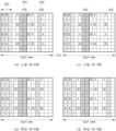
도 16은 IoT 기지국이 여러 개의 채널을 통해 단말들과 신호를 송수신하는 예시를 나타낸 도이다.
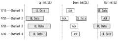
도 17은 IoT 기지국이 여러 개의 채널을 통해 단말들과 신호를 송수신하는 또 다른 예시를 나타낸 도이다.
도 18은 본 개시에서 제안하는 신호 송수신 방법이 수행되는 일 예를 나타낸 도이다.
도 19는 본 개시에서 제안하는 신호를 송수신하기 위한 방법이 단말에서 수행되는 일 예를 나타낸 흐름도이다.
도 20은 본 개시에서 제안하는 신호를 송수신하기 위한 방법이 기지국에서 수행되는 일 예를 나타낸 흐름도이다.The accompanying drawings, which are incorporated in and are intended to aid in the understanding of the present disclosure and are incorporated in and constitute a part of the detailed description, provide embodiments of the present disclosure and together with the detailed description, describe the technical features of the present disclosure.
FIG. 1 illustrates an example of a wireless network according to embodiments of the present disclosure.
FIG. 2 illustrates an example of a base station according to embodiments of the present disclosure.
FIG. 3 illustrates an example of a terminal according to embodiments of the present disclosure.
FIG. 4 is a diagram showing the basic structure of a time-frequency domain, which is a radio resource domain in which data or control channels are transmitted, in an NR system according to one embodiment of the present disclosure.
Figures 5 and 6 schematically illustrate the structure of a wireless frame applied to the present disclosure.
Figure 7 is a diagram illustrating various deployment scenarios of an NB-IoT system.
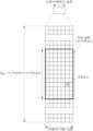
Figure 8 is a diagram illustrating a resource grid corresponding to one subframe in an NB-IoT system.
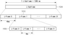
Figure 9 is a diagram illustrating the structure of an L-subframe in an NB-IoT system.
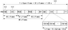
Figure 10 is a diagram illustrating the structure of an L-superframe in an NB-IoT system.
Figure 11 is a diagram illustrating the downlink time domain structure in an NB-IoT system.
Figure 12 is a diagram illustrating PSS/SSS transmission in an NB-IoT system.
Figure 13 is a diagram illustrating an example of PSS transmission in an NB-IoT system.
Figure 14 is a diagram illustrating an example of PBCH transmission in an NB-IoT system.
Figure 15 is a diagram illustrating PSS/SSS/MIB transmission of an NB-IoT system in the time domain to avoid collision with PSS/SSS/MIB of a legacy system.
Figure 16 is a diagram showing an example of an IoT base station transmitting and receiving signals with terminals through multiple channels.
Figure 17 is another example showing an IoT base station transmitting and receiving signals with terminals through multiple channels.
FIG. 18 is a diagram showing an example of performing the signal transmission and reception method proposed in the present disclosure.
FIG. 19 is a flowchart showing an example of a method for transmitting and receiving a signal proposed in the present disclosure performed at a terminal.
FIG. 20 is a flowchart showing an example of a method for transmitting and receiving a signal proposed in the present disclosure performed at a base station.
본 개시의 다양한 실시 예에서, "/" 및 ","는 "및/또는"을 나타내는 것으로 해석되어야 한다. 예를 들어, "A/B"는 "A 및/또는 B"를 의미할 수 있다. 나아가, "A, B"는 "A 및/또는 B"를 의미할 수 있다. 나아가, "A/B/C"는 "A, B 및/또는 C 중 적어도 어느 하나"를 의미할 수 있다. 나아가, "A, B, C"는 "A, B 및/또는 C 중 적어도 어느 하나"를 의미할 수 있다.In various embodiments of the present disclosure, "/" and "," should be interpreted as representing "and/or". For example, "A/B" can mean "A and/or B". Furthermore, "A, B" can mean "A and/or B". Furthermore, "A/B/C" can mean "at least one of A, B, and/or C". Furthermore, "A, B, C" can mean "at least one of A, B, and/or C".
본 개시의 다양한 실시 예에서, "또는"은 "및/또는"을 나타내는 것으로 해석되어야 한다. 예를 들어, "A 또는 B"는 "오직 A", "오직 B", 및/또는 "A 및 B 모두"를 포함할 수 있다. 다시 말해, "또는"은 "부가적으로 또는 대안적으로"를 나타내는 것으로 해석되어야 한다.In various embodiments of the present disclosure, "or" should be interpreted as meaning "and/or." For example, "A or B" can include "only A," "only B," and/or "both A and B." In other words, "or" should be interpreted as meaning "additionally or alternatively."
이하의 기술은 CDMA(code division multiple access), FDMA(frequency division multiple access), TDMA(time division multiple access), OFDMA(orthogonal frequency division multiple access), SC-FDMA(single carrier frequency division multiple access) 등과 같은 다양한 무선 통신 시스템에 사용될 수 있다. CDMA는 UTRA(universal terrestrial radio access)나 CDMA2000과 같은 무선 기술로 구현될 수 있다. TDMA는 GSM(global system for mobile communications)/GPRS(general packet radio service)/EDGE(enhanced data rates for GSM evolution)와 같은 무선 기술로 구현될 수 있다. OFDMA는 IEEE(institute of electrical and electronics engineers) 802.11(Wi-Fi), IEEE 802.16(WiMAX), IEEE 802-20, E-UTRA(evolved UTRA) 등과 같은 무선 기술로 구현될 수 있다. IEEE 802.16m은 IEEE 802.16e의 진화로, IEEE 802.16e에 기반한 시스템과의 하위 호환성(backward compatibility)를 제공한다. UTRA는 UMTS(universal mobile telecommunications system)의 일부이다. 3GPP(3rd generation partnership project) LTE(long term evolution)은 E-UTRA(evolved-UMTS terrestrial radio access)를 사용하는 E-UMTS(evolved UMTS)의 일부로써, 하향링크에서 OFDMA를 채용하고 상향링크에서 SC-FDMA를 채용한다. LTE-A(advanced)는 3GPP LTE의 진화이다.The following technology can be used in various wireless communication systems, such as CDMA (code division multiple access), FDMA (frequency division multiple access), TDMA (time division multiple access), OFDMA (orthogonal frequency division multiple access), and SC-FDMA (single carrier frequency division multiple access). CDMA can be implemented with wireless technologies such as UTRA (universal terrestrial radio access) or CDMA2000. TDMA can be implemented with wireless technologies such as GSM (global system for mobile communications)/GPRS (general packet radio service)/EDGE (enhanced data rates for GSM evolution). OFDMA can be implemented with wireless technologies such as IEEE (institute of electrical and electronics engineers) 802.11 (Wi-Fi), IEEE 802.16 (WiMAX), IEEE 802-20, E-UTRA (evolved UTRA). IEEE 802.16m is an evolution of IEEE 802.16e, providing backward compatibility with systems based on IEEE 802.16e. UTRA is part of UMTS (universal mobile telecommunications system). 3GPP (3rd generation partnership project) LTE (long term evolution) is a part of E-UMTS (evolved UMTS) that uses E-UTRA (evolved-UMTS terrestrial radio access), employing OFDMA in the downlink and SC-FDMA in the uplink. LTE-A (advanced) is an evolution of 3GPP LTE.
5G NR은 LTE-A의 후속 기술로서, 고성능, 저지연, 고가용성 등의 특성을 가지는 새로운 Clean-slate 형태의 이동 통신 시스템이다. 5G NR은 1GHz 미만의 저주파 대역에서부터 1GHz~10GHz의 중간 주파 대역, 24GHz 이상의 고주파(밀리미터파) 대역 등 사용 가능한 모든 스펙트럼 자원을 활용할 수 있다.5G NR is a new clean-slate type mobile communication system that is the successor technology to LTE-A and has the characteristics of high performance, low latency, and high availability. 5G NR can utilize all available spectrum resources, from low frequency bands below 1 GHz to intermediate frequency bands between 1 GHz and 10 GHz, and high frequency (millimeter wave) bands above 24 GHz.
설명을 명확하게 하기 위해, LTE-A 또는 5G NR을 위주로 기술하지만 본 개시의 일 실시 예에 따른 기술적 사상이 이에 제한되는 것은 아니다.For clarity of explanation, the description will focus on LTE-A or 5G NR, but the technical ideas according to one embodiment of the present disclosure are not limited thereto.
4G 통신 시스템 상용화 이후 증가 추세에 있는 무선 데이터 트래픽 수요를 충족시키기 위해, 개선된 5G 통신 시스템 또는 pre-5G 통신 시스템을 개발하기 위한 노력이 이루어지고 있다. 이러한 이유로, 5G 통신 시스템 또는 pre-5G 통신 시스템은 4G 네트워크 이후 (Beyond 4G Network) 통신 시스템 또는 LTE 시스템 이후 (Post LTE) 이후의 시스템이라 불리어지고 있다. 3GPP에서 정한 5G 통신 시스템은 New Radio (NR) 시스템이라고 불리고 있다. 높은 데이터 전송률을 달성하기 위해, 5G 통신 시스템은 초고주파(mmWave) 대역 (예를 들어, 60기가(60GHz) 대역과 같은)에서의 구현이 고려되고 있다. 초고주파 대역에서의 전파의 경로손실 완화 및 전파의 전달 거리를 증가시키기 위해, 5G 통신 시스템에서는 빔포밍(beamforming), 거대 배열 다중 입출력(massive MIMO), 전차원 다중입출력(Full Dimensional MIMO: FD-MIMO), 어레이 안테나(array antenna), 아날로그 빔형성(analog beam-forming), 및 대규모 안테나 (large scale antenna) 기술들이 논의되었고, NR 시스템에 적용되었다. 또한 시스템의 네트워크 개선을 위해, 5G 통신 시스템에서는 진화된 소형 셀, 개선된 소형 셀 (advanced small cell), 클라우드 무선 액세스 네트워크 (cloud radio access network: cloud RAN), 초고밀도 네트워크 (ultra-dense network), 기기 간 통신 (Device to Device communication: D2D), 무선 백홀 (wireless backhaul), 이동 네트워크 (moving network), 협력 통신 (cooperative communication), CoMP (Coordinated Multi-Points), 및 수신 간섭제거 (interference cancellation) 등의 기술 개발이 이루어지고 있다. 이 밖에도, 5G 시스템에서는 진보된 코딩 변조(Advanced Coding Modulation: ACM) 방식인 FQAM (Hybrid FSK and QAM Modulation) 및 SWSC (Sliding Window Superposition Coding)과, 진보된 접속 기술인 FBMC(Filter Bank Multi Carrier), NOMA(non-orthogonal multiple access), 및 SCMA(sparse code multiple access) 등이 개발되고 있다.In order to meet the increasing demand for wireless data traffic since the commercialization of 4G communication systems, efforts are being made to develop improved 5G communication systems or pre-5G communication systems. For this reason, 5G communication systems or pre-5G communication systems are also called Beyond 4G Network communication systems or Post LTE systems. The 5G communication system specified by 3GPP is called the New Radio (NR) system. In order to achieve high data transmission rates, 5G communication systems are being considered for implementation in ultra-high frequency (mmWave) bands (e.g., 60 gigahertz (60 GHz) bands). To mitigate radio path loss and increase the transmission range of radio waves in ultra-high frequency bands, beamforming, massive MIMO, full-dimensional MIMO (FD-MIMO), array antenna, analog beam-forming, and large scale antenna technologies have been discussed and applied to NR systems in 5G communication systems. In addition, to improve the network of the system, technologies such as evolved small cell, advanced small cell, cloud radio access network (cloud RAN), ultra-dense network, device to device communication (D2D), wireless backhaul, moving network, cooperative communication, Coordinated Multi-Points (CoMP), and interference cancellation are being developed in 5G communication systems. In addition, advanced coding modulation (ACM) methods such as FQAM (Hybrid FSK and QAM Modulation) and SWSC (Sliding Window Superposition Coding), as well as advanced access technologies such as FBMC (Filter Bank Multi Carrier), NOMA (non-orthogonal multiple access), and SCMA (sparse code multiple access) are being developed in 5G systems.
한편, 인터넷은 인간이 정보를 생성하고 소비하는 인간 중심의 연결 망에서, 사물 등 분산된 구성 요소들 간에 정보를 주고 받아 처리하는 IoT(Internet of Things, 사물인터넷) 망으로 진화하고 있다. 클라우드 서버 등과의 연결을 통한 빅데이터(Big data) 처리 기술 등이 IoT 기술에 결합된 IoE (Internet of Everything) 기술도 대두되고 있다. IoT를 구현하기 위해서, 센싱 기술, 유무선 통신 및 네트워크 인프라, 서비스 인터페이스 기술, 및 보안 기술과 같은 기술 요소 들이 요구되어, 최근에는 사물간의 연결을 위한 센서 네트워크(sensor network), 사물 통신(Machine to Machine, M2M), MTC(Machine Type Communication)등의 기술이 연구되고 있다. IoT 환경에서는 연결된 사물들에서 생성된 데이터를 수집, 분석하여 인간의 삶에 새로운 가치를 창출하는 지능형 IT(Internet Technology) 서비스가 제공될 수 있다. IoT는 기존의 IT(information technology)기술과 다양한 산업 간의 융합 및 복합을 통하여 스마트홈, 스마트 빌딩, 스마트 시티, 스마트 카 혹은 커넥티드 카, 스마트 그리드, 헬스 케어, 스마트 가전, 첨단의료서비스 등의 분야에 응용될 수 있다.Meanwhile, the Internet is evolving from a human-centered network where humans create and consume information to an Internet of Things (IoT) network where information is exchanged and processed between distributed components such as objects. IoE (Internet of Everything) technology, which combines IoT technology with big data processing technology through connection to cloud servers, is also emerging. In order to implement IoT, technological elements such as sensing technology, wireless communication and network infrastructure, service interface technology, and security technology are required, and recently, technologies such as sensor networks for connection between objects, machine-to-machine (M2M), and machine type communication (MTC) are being studied. In the IoT environment, intelligent IT (Internet Technology) services can be provided that collect and analyze data generated from connected objects to create new values for human life. IoT can be applied to fields such as smart homes, smart buildings, smart cities, smart cars or connected cars, smart grids, healthcare, smart home appliances, and advanced medical services through convergence and combination between existing IT (information technology) technologies and various industries.
이에, 5G 통신 시스템을 IoT 망에 적용하기 위한 다양한 시도들이 이루어지고 있다. 예를 들어, 센서 네트워크(sensor network), 사물 통신(Machine to Machine, M2M), MTC(Machine Type Communication)등의 기술이 5G 통신 기술인 빔 포밍, MIMO, 및 어레이 안테나 등의 기법에 의해 구현되고 있는 것이다. 앞서 설명한 빅데이터 처리 기술로써 클라우드 무선 액세스 네트워크(cloud RAN)가 적용되는 것도 5G 기술과 IoT 기술 융합의 일 예라고 할 수 있을 것이다.Accordingly, various attempts are being made to apply 5G communication systems to IoT networks. For example, technologies such as sensor networks, machine-to-machine (M2M), and machine-type communication (MTC) are being implemented by 5G communication technologies such as beam forming, MIMO, and array antennas. The application of cloud radio access networks (cloud RAN) as a big data processing technology described above can also be said to be an example of the convergence of 5G and IoT technologies.
한편, 새로운 5G 통신인 NR (New Radio access technology)에서는 시간 및 주파수 자원에서 다양한 서비스들이 자유롭게 다중화 될 수 있도록 하기 위하여 디자인되고 있으며, 이에 따라 waveform/numerology 등과 기준 신호 등이 해당 서비스의 필요에 따라 동적으로 혹은 자유롭게 할당될 수 있다. 무선 통신에서 단말에게 최적의 서비스를 제공하기 위해서는 채널의 질과 간섭량의 측정을 통한 최적화 된 데이터 송신이 중요하며, 이에 따라 정확한 채널 상태 측정은 필수적이다. 하지만, 주파수 자원에 따라 채널 및 간섭 특성이 크게 변화하지 않는 4G 통신과는 달리 5G 채널의 경우 서비스에 따라 채널 및 간섭 특성이 크게 변화하기 때문에 이를 나누어 측정할 수 있도록 하는 FRG(Frequency Resource Group) 차원의 subset의 지원이 필요하다. 한편, NR 시스템에서는 지원되는 서비스의 종류를 eMBB (Enhanced mobile broadband), mMTC (massive Machine Type Communications) (mMTC), URLLC (Ultra-Reliable and low-latency Communications) 등의 카테고리로 나눌 수 있다. eMBB는 고용량데이터의 고속 전송, mMTC는 단말전력 최소화와 다수 단말의 접속, URLLC는 고신뢰도와 저지연을 목표로 하는 서비스라고 볼 수 있다. 단말에게 적용되는 서비스의 종류에 따라 서로 다른 요구사항들이 적용될 수 있다.Meanwhile, the new 5G communication, NR (New Radio access technology), is designed to allow various services to be freely multiplexed in time and frequency resources, and accordingly, waveform/numerology, etc. and reference signals can be dynamically or freely allocated according to the needs of the corresponding service. In order to provide the optimal service to the terminal in wireless communication, optimized data transmission through measurement of channel quality and interference amount is important, and therefore accurate channel status measurement is essential. However, unlike 4G communication where channel and interference characteristics do not change significantly depending on frequency resources, in the case of 5G channels, channel and interference characteristics change significantly depending on the service, so support for subsets at the FRG (Frequency Resource Group) level is required to allow for dividing and measuring them. Meanwhile, the types of services supported in the NR system can be divided into categories such as eMBB (Enhanced mobile broadband), mMTC (massive Machine Type Communications) (mMTC), and URLLC (Ultra-Reliable and low-latency Communications). eMBB can be seen as a service that aims for high-speed transmission of large-capacity data, mMTC as a service that aims for minimizing terminal power and connecting multiple terminals, and URLLC as a service that aims for high reliability and low delay. Different requirements may be applied depending on the type of service applied to the terminal.
이와 같이 통신 시스템에서 복수의 서비스가 사용자에게 제공될 수 있으며, 이와 같은 복수의 서비스를 사용자에게 제공하기 위해 특징에 맞게 각 서비스를 동일한 시구간 내에서 제공할 수 있는 방법 및 이를 이용한 장치가 요구된다.In this way, multiple services can be provided to users in a communication system, and in order to provide such multiple services to users, a method and a device using the same are required that can provide each service within the same time period according to its characteristics.
이하, 본 개시의 실시 예를 첨부된 도면을 참조하여 상세하게 설명한다.Hereinafter, embodiments of the present disclosure will be described in detail with reference to the attached drawings.
실시 예를 설명함에 있어서 본 개시가 속하는 기술 분야에 익히 알려져 있고 본 개시와 직접적으로 관련이 없는 기술 내용에 대해서는 설명을 생략한다. 이는 불필요한 설명을 생략함으로써 본 개시의 요지를 흐리지 않고 더욱 명확히 전달하기 위함이다.In describing the embodiments, descriptions of technical contents that are well known in the technical field to which the present disclosure belongs and are not directly related to the present disclosure will be omitted. This is to convey the gist of the present disclosure more clearly without obscuring it by omitting unnecessary descriptions.
마찬가지 이유로 첨부 도면에 있어서 일부 구성요소는 과장되거나 생략되거나 개략적으로 도시되었다. 또한, 각 구성요소의 크기는 실제 크기를 전적으로 반영하는 것이 아니다. 각 도면에서 동일한 또는 대응하는 구성요소에는 동일한 참조 번호를 부여하였다.For the same reason, some components in the attached drawings are exaggerated, omitted, or schematically illustrated. In addition, the size of each component does not entirely reflect the actual size. The same or corresponding components in each drawing are given the same reference numbers.
본 개시의 이점 및 특징, 그리고 그것들을 달성하는 방법은 첨부되는 도면과 함께 상세하게 후술되어 있는 실시 예들을 참조하면 명확해질 것이다. 그러나 본 개시는 이하에서 개시되는 실시 예들에 한정되는 것이 아니라 서로 다른 다양한 형태로 구현될 수 있으며, 단지 본 실시 예들은 본 개시의 개시가 완전하도록 하고, 본 개시가 속하는 기술분야에서 통상의 지식을 가진 자에게 개시의 범주를 완전하게 알려주기 위해 제공되는 것이며, 본 개시는 청구항의 범주에 의해 정의될 뿐이다. 개시 전체에 걸쳐 동일 참조 부호는 동일 구성 요소를 지칭한다.The advantages and features of the present disclosure, and the methods for achieving them, will become apparent by referring to the embodiments described in detail below together with the accompanying drawings. However, the present disclosure is not limited to the embodiments disclosed below and may be implemented in various different forms, and the embodiments are provided only to make the disclosure of the present disclosure complete and to fully inform those skilled in the art of the scope of the disclosure, and the present disclosure is defined only by the scope of the claims. Like reference numerals refer to like elements throughout the disclosure.
이 때, 처리 흐름도 도면들의 각 블록과 흐름도 도면들의 조합들은 컴퓨터 프로그램 인스트럭션들에 의해 수행될 수 있음을 이해할 수 있을 것이다. 이들 컴퓨터 프로그램 인스트럭션들은 범용 컴퓨터, 특수용 컴퓨터 또는 기타 프로그램 가능한 데이터 프로세싱 장비의 프로세서에 탑재될 수 있으므로, 컴퓨터 또는 기타 프로그램 가능한 데이터 프로세싱 장비의 프로세서를 통해 수행되는 그 인스트럭션들이 흐름도 블록(들)에서 설명된 기능들을 수행하는 수단을 생성하게 된다. 이들 컴퓨터 프로그램 인스트럭션들은 특정 방식으로 기능을 구현하기 위해 컴퓨터 또는 기타 프로그램 가능한 데이터 프로세싱 장비를 지향할 수 있는 컴퓨터 이용 가능 또는 컴퓨터 판독 가능 메모리에 저장되는 것도 가능하므로, 그 컴퓨터 이용가능 또는 컴퓨터 판독 가능 메모리에 저장된 인스트럭션들은 흐름도 블록(들)에서 설명된 기능을 수행하는 인스트럭션 수단을 내포하는 제조 품목을 생산하는 것도 가능하다. 컴퓨터 프로그램 인스트럭션들은 컴퓨터 또는 기타 프로그램 가능한 데이터 프로세싱 장비 상에 탑재되는 것도 가능하므로, 컴퓨터 또는 기타 프로그램 가능한 데이터 프로세싱 장비 상에서 일련의 동작 단계들이 수행되어 컴퓨터로 실행되는 프로세스를 생성해서 컴퓨터 또는 기타 프로그램 가능한 데이터 프로세싱 장비를 수행하는 인스트럭션들은 흐름도 블록(들)에서 설명된 기능들을 실행하기 위한 단계들을 제공하는 것도 가능하다.At this time, it will be understood that each block of the processing flow diagrams and combinations of the flow diagrams can be performed by computer program instructions. These computer program instructions can be loaded onto a processor of a general-purpose computer, a special-purpose computer, or other programmable data processing equipment, so that the instructions executed by the processor of the computer or other programmable data processing equipment create a means for performing the functions described in the flow diagram block(s). These computer program instructions can also be stored in a computer-available or computer-readable memory that can be directed to a computer or other programmable data processing equipment to implement the function in a specific manner, so that the instructions stored in the computer-available or computer-readable memory can also produce a manufactured article including an instruction means for performing the functions described in the flow diagram block(s). Since the computer program instructions may be installed on a computer or other programmable data processing apparatus, a series of operational steps may be performed on the computer or other programmable data processing apparatus to produce a computer-executable process, so that the instructions executing the computer or other programmable data processing apparatus may also provide steps for executing the functions described in the flowchart block(s).
또한, 각 블록은 특정된 논리적 기능(들)을 실행하기 위한 하나 이상의 실행 가능한 인스트럭션들을 포함하는 모듈, 세그먼트 또는 코드의 일부를 나타낼 수 있다. 또, 몇 가지 대체 실행 예들에서는 블록들에서 언급된 기능들이 순서를 벗어나서 발생하는 것도 가능함을 주목해야 한다. 예컨대, 잇달아 도시되어 있는 두 개의 블록들은 사실 실질적으로 동시에 수행되는 것도 가능하고 또는 그 블록들이 때때로 해당하는 기능에 따라 역순으로 수행되는 것도 가능하다.Additionally, each block may represent a module, segment, or portion of code that contains one or more executable instructions for performing a particular logical function(s). It should also be noted that in some alternative implementation examples, the functions mentioned in the blocks may occur out of order. For example, two blocks shown in succession may in fact be performed substantially concurrently, or the blocks may sometimes be performed in reverse order, depending on the functionality they perform.
이 때, 본 실시 예에서 사용되는 '~부'라는 용어는 소프트웨어 또는 FPGA또는 ASIC과 같은 하드웨어 구성요소를 의미하며, '~부'는 어떤 역할들을 수행한다. 그렇지만 '~부'는 소프트웨어 또는 하드웨어에 한정되는 의미는 아니다. '~부'는 어드레싱할 수 있는 저장 매체에 있도록 구성될 수도 있고 하나 또는 그 이상의 프로세서들을 재생시키도록 구성될 수도 있다. 따라서, 일 예로서 '~부'는 소프트웨어 구성요소들, 객체지향 소프트웨어 구성요소들, 클래스 구성요소들 및 태스크 구성요소들과 같은 구성요소들과, 프로세스들, 함수들, 속성들, 프로시저들, 서브루틴들, 프로그램 코드의 세그먼트들, 드라이버들, 펌웨어, 마이크로코드, 회로, 데이터, 데이터베이스, 데이터 구조들, 테이블들, 어레이들, 및 변수들을 포함한다. 구성요소들과 '~부'들 안에서 제공되는 기능은 더 작은 수의 구성요소들 및 '~부'들로 결합되거나 추가적인 구성요소들과 '~부'들로 더 분리될 수 있다. 뿐만 아니라, 구성요소들 및 '~부'들은 디바이스 또는 보안 멀티미디어카드 내의 하나 또는 그 이상의 CPU들을 재생시키도록 구현될 수도 있다. 또한 실시 예에서 '~부'는 하나 이상의 프로세서를 포함할 수 있다.Here, the term '~ part' used in the present embodiment means a software or hardware component such as an FPGA or ASIC, and the '~ part' performs certain roles. However, the '~ part' is not limited to software or hardware. The '~ part' may be configured to be in an addressable storage medium and may be configured to reproduce one or more processors. Thus, as an example, the '~ part' includes components such as software components, object-oriented software components, class components, and task components, processes, functions, properties, procedures, subroutines, segments of program code, drivers, firmware, microcode, circuits, data, databases, data structures, tables, arrays, and variables. The functions provided in the components and '~ parts' may be combined into a smaller number of components and '~ parts' or further separated into additional components and '~ parts'. In addition, the components and '~ parts' may be implemented to reproduce one or more CPUs in a device or a secure multimedia card. Additionally, in the embodiment, '~bu' may include one or more processors.
무선 통신 시스템은 초기의 음성 위주의 서비스를 제공하던 것에서 벗어나 예를 들어, 3GPP의 HSPA (high speed Packet Access), LTE (long term evolution 혹은 E-UTRA (evolved universal terrestrial radio access)), LTE-Advanced (LTE-A), 3GPP2의 HRPD (high rate packet data), UMB (ultra mobile broadband), 및 IEEE의 802.16e 등의 통신 표준과 같이 고속, 고품질의 패킷 데이터 서비스를 제공하는 광대역 무선 통신 시스템으로 발전하고 있다. 또한, 5세대 무선통신 시스템으로 5G 혹은 NR (new radio)의 통신표준이 만들어지고 있다.Wireless communication systems are evolving from the initial voice-oriented services to broadband wireless communication systems that provide high-speed, high-quality packet data services, such as 3GPP's HSPA (high speed Packet Access), LTE (long term evolution or E-UTRA (evolved universal terrestrial radio access)), LTE-Advanced (LTE-A), 3GPP2's HRPD (high rate packet data), UMB (ultra mobile broadband), and IEEE's 802.16e. In addition, communication standards for 5G or NR (new radio) are being created as the 5th generation wireless communication system.
광대역 무선 통신 시스템의 대표적인 예로, NR 시스템에서는 하향링크 (downlink; DL) 및 상향링크에서는 OFDM (orthogonal frequency division multiplexing) 방식을 채용하고 있다. 다만 보다 구체적으로는 하향링크에서는 CP-OFDM (cyclic-prefix OFDM) 방식이 채용되었고, 상향링크에서는 CP-OFDM과 더불어 DFT-S-OFDM (discrete Fourier transform spreading OFDM) 방식 두 가지가 채용되었다. 상향링크는 단말 (user equipment: UE) 혹은 MS (mobile station))이 기지국(gNode B, 혹은 base station(BS))으로 데이터 혹은 제어신호를 전송하는 무선링크를 뜻하고, 하향링크는 기지국이 단말로 데이터 혹은 제어신호를 전송하는 무선링크를 뜻한다. 상기와 같은 다중 접속 방식은, 통상 각 사용자 별로 데이터 혹은 제어정보를 실어 보낼 시간-주파수 자원을 서로 겹치지 않도록, 즉 직교성 (Orthogonality)이 성립하도록, 할당 및 운용함으로써 각 사용자의 데이터 혹은 제어정보를 구분한다.As a representative example of a wideband wireless communication system, the NR system adopts the OFDM (orthogonal frequency division multiplexing) method in the downlink (DL) and uplink. More specifically, the CP-OFDM (cyclic-prefix OFDM) method is adopted in the downlink, and both the CP-OFDM and the DFT-S-OFDM (discrete Fourier transform spreading OFDM) method are adopted in the uplink. The uplink refers to a wireless link in which a user equipment (UE) or mobile station (MS) transmits data or a control signal to a base station (gNode B or base station (BS)), and the downlink refers to a wireless link in which a base station transmits data or a control signal to a user equipment (UE). The above multiple access method typically allocates and operates the time-frequency resources for transmitting data or control information to each user so that they do not overlap with each other, that is, so as to achieve orthogonality, thereby distinguishing the data or control information of each user.
기지국(Base Station)은 단말과 통신하는 일 주체로서, BS, NodeB(NB), eNodB(eNB), AP(Access Point) 등으로 지칭될 수도 있다.The base station is the entity that communicates with the terminal, and may also be referred to as BS, NodeB (NB), eNodB (eNB), AP (Access Point), etc.
디바이스(device)는 기지국과 통신하는 일 주체로서, NB-IoT 디바이스, UE(user equipment), 이동국(Mobile Station; MS), 이동장비(Mobile Equipment; ME), 터미널(terminal) 등으로 지칭될 수도 있다.A device is an entity that communicates with a base station and may be referred to as an NB-IoT device, UE (user equipment), Mobile Station (MS), Mobile Equipment (ME), terminal, etc.
무선 네트워크 일반Wireless Network General
도 1 내지 3은 아래에 개시된 무선 통신 시스템에서 구현되고 직교 주파수 분할 다중방식(orthogonal frequency division multiplexing, OFDM) 또는 직교 주파수 분할 다중 접속(orthogonal frequency division multiple access)을 사용하는 다양한 실시 예를 설명한다.FIGS. 1 to 3 illustrate various embodiments implemented in the wireless communication system disclosed below and utilizing orthogonal frequency division multiplexing (OFDM) or orthogonal frequency division multiple access.
도 1 내지 3은 다른 실시 예들이 구현될 수 있는 방식에 물리적 또는 구조적 제한을 의미하는 것은 아니다. 본 개시의 다른 실시 예는 임의의 적절하게 배열된 통신 시스템에서 구현될 수 있다.FIGS. 1-3 are not intended to imply physical or structural limitations on the manner in which other embodiments may be implemented. Other embodiments of the present disclosure may be implemented in any suitably arranged communication system.
도 1은 본 개시의 실시 예들에 따른 무선 네트워크의 일 예를 도시한다. 도1에 도시된 무선 네트워크의 실시 예은 단지 설명을 위한 것일 뿐이다. 상기 무선 네트워크 100의 다른 실시 예들은 본 개시의 범위를 벗어나지 않고 사용될 수 있다.FIG. 1 illustrates an example of a wireless network according to embodiments of the present disclosure. The embodiment of the wireless network illustrated in FIG. 1 is for illustrative purposes only. Other embodiments of the
도 1에 도시된 바와 같이, 무선 네트워크는 gNB 101, gNB 102, gNB 103을 포함할 수 있다. 또한, gNB 101는 적어도 하나의 네트워크 103, 예를 들어, 인터넷(internet), 독점 IP(internet protocol) 네트워크, 또는 다른 데이터 네트워크, 와 통신할 수 있다.As illustrated in FIG. 1, the wireless network may include
gNB 102는 gNB 102의 커버리지 영역 120 내의 제1 복수의 사용자 장비(user equipment, UE)에 대해 네트워크 130에 대한 무선 광대역 액세스를 제공할 수 있다. 상기 제1 복수의 사용자 장비는 스몰 비즈니스(small business, SB)에 위치할 수 있는 사용자 장치 111, 엔터프라이(enterprise, E)에 위치할 수 있는 사용자 장치 112, WIFI 핫스팟(hotspot, HS)에 위치할 수 있는 사용자 장치 113, 제1 레지던스(residence, R)에 위치할 수 있는 UE 114, 제2 레지던스(residence, R)에 위치할 수 있는 UE 115, 모바일 장치(mobile device, M)에 위치할 수 있는 UE 115, 예를 들어, 휴대폰(cell phone), 무선 랩탑(wireless laptop), 무선 PDF, 또는 이와 같은 모바일 장치를 포함할 수 있다.A
gNB 103는 gNB 103의 커버리지 영역 125 내의 제2 복수의 UE에 대해 네트워크 130에 대한 무선 광대역 액세스를 제공할 수 있다. 제2 복수의 UE는 UE 115, UE 116을 포함할 수 있다. 일 실시 예에 따르면, 적어도 하나 이상의 gNB들 101-103은 5G, LTE, LTE-A, WiMAX, WIFI, 다른 무선 통신 기술을 사용하여 서로 간에 혹은 UE들 111-116과 통신을 수행할 수 있다.The
네트워크 유형에 따라 "기지국"또는 "base station", BS"라는 용어는 전송 지점 (transmit point, TP), 전송-수신 지점 (transmit-receive point, TRP), 강화 된 기지국 (eNodeB 또는 eNB), 5G 기지국 (gNB), 매크로 셀, 펨토셀, WiFi 액세스 포인트 (AP) 또는 기타 무선 지원 장치와 같이 네트워크에 무선 액세스를 제공하도록 구성된 모든 구성 요소 (또는 구성 요소 모음)를 나타낼 수 있다.Depending on the network type, the term "base station" or "BS" may refer to any component (or collection of components) configured to provide wireless access to the network, such as a transmit point (TP), a transmit-receive point (TRP), an enhanced base station (eNodeB or eNB), a 5G base station (gNB), a macro cell, a femtocell, a WiFi access point (AP), or other radio-enabled device.
기지국은 하나 이상의 무선 통신 프로토콜, 예를 들어, 5G 3GPP 새로운 무선 인터페이스/액세스 (NR), 장기 진화 (LTE), LTE 고급 (LTE-A), 고속 패킷 액세스 (HSPA)), Wi-Fi 802.11a/b/g/n/ac 등에 따라 무선 액세스를 제공할 수 있다. 편의상 "BS"와 "TRP"라는 용어는 원격 단말기에 무선 액세스를 제공하는 네트워크 인프라 구성 요소를 지칭하기 위해 본 특허 문서에서 상호 교환 적으로 사용됩니다. 또한 네트워크 유형에 따라 "사용자 장비"또는 "UE"라는 용어는 "모바일 스테이션", "가입자", "원격 터미널 ", "무선 터미널 ","수신 지점" 또는 "사용자 장치"와 같은 모든 구성 요소를 지칭할 수 있다.A base station may provide wireless access according to one or more wireless communication protocols, e.g., 5G 3GPP New Radio Interface/Access (NR), Long Term Evolution (LTE), LTE Advanced (LTE-A), High-Speed Packet Access (HSPA)), Wi-Fi 802.11a/b/g/n/ac, etc. For convenience, the terms "BS" and "TRP" are used interchangeably in this patent document to refer to a network infrastructure component that provides wireless access to a remote terminal. Additionally, depending on the network type, the term "user equipment" or "UE" may refer to any component, such as a "mobile station", "subscriber", "remote terminal", "wireless terminal", "receiving point" or "user device".
편의상 본 특허 문서에서 "사용자 장비"및 "UE"라는 용어는 BS에 무선으로 액세스하는 원격 무선 장비를 지칭하기 위해 사용되고, UE는 모바일 장치 (예: 모바일 전화 또는 스마트 폰)이거나 일반적으로 고정 장치 (예: 데스크톱 컴퓨터 또는 자동 판매기)로 간주된다.For convenience, the terms “user equipment” and “UE” are used in this patent document to refer to remote wireless equipment that wirelessly accesses a BS, wherein the UE may be a mobile device (e.g., a mobile phone or a smart phone) or generally considered a stationary device (e.g., a desktop computer or a vending machine).
점선은 단지 예시 및 설명을 위해 대략 원형으로 도시 된 커버리지 영역 120, 및 125의 대략적인 범위를 나타낸다. gNB와 관련된 커버리지 영역 120 및 125은 gNB의 구성, 자연 및 인간에 의하여 만들어진 장애물과 관련된 무선 환경의 변화에 따라 불규칙한 모양을 포함한 다른 모양을 가질 수 있다.The dotted lines represent approximate extents of
아래에서 더 상세히 설명되는 바와 같이, 적어도 하나 이상의 UE들 111-116은 고급 무선 통신 시스템에서 데이터 및 제어 정보에 대한 수신 신뢰성을 위한 회로, 프로그래밍 또는 이들의 조합을 포함할 수 있다. 특정 실시 예에서, 적어도 하나 이상의 gNB 101-103는 NR (New Radio) V2X (vehicle-to-everything)에서 효율적인 네트워크 제어 자원 할당을 위한 회로, 프로그래밍 또는 이들의 조합을 포함할 수 있다.As described in more detail below, at least one of the UEs 111-116 may include circuitry, programming or a combination thereof for reception reliability for data and control information in an advanced wireless communication system. In certain embodiments, at least one of the gNBs 101-103 may include circuitry, programming or a combination thereof for efficient network control resource allocation in New Radio (NR) vehicle-to-everything (V2X).
도 1은 무선 네트워크의 일 예를 도시하고 있으나, 도 1에 다양한 변경들이 이루어질 수 있다. 예를 들어, 무선 네트워크는 임의의 적절한 배열 안에서 임의의 수의 gNB 및 임의의 수의 UE을 포함할 수 있다. 또한, gNB 101는 임의의 수의 UE들과 직접 통신할 수 있고 이들 UE들에게 네트워크 130에 대한 무선 광대역 액세스를 제공할 수 있다. 유사하게, 각각의 gNB 102-103는 네트워크 130와 직접 통신할 수 있고 UE들에게 네트워크 130에 대한 직접적인 무선 광대역 액세스를 제공할 수 있다. 또한, gNB 101, 102 및/또는 103은 외부 전화 네트워크 또는 다른 유형의 데이터 네트워크와 같은 다른 또는 추가 외부 네트워크에 대한 액세스를 제공할 수 있다.While FIG. 1 illustrates an example of a wireless network, various modifications may be made to FIG. 1 . For example, the wireless network may include any number of gNBs and any number of UEs in any suitable arrangement. In addition,
도 2는 본 개시의 실시 예들에 따른 gNB 102의 일 예를 도시한다. 도 1에 예시된 gNB 102의 실시 예는 단지 예시를 위한 것이고, 도 1의 gNB 101 및 gNB 103는 동일하거나 유사한 구성을 가질 수 있다. 다만, gNB는 다양한 구성으로 제공될 수 있고, 도 2는 개시의 범위를 gNB의 임의의 특정 구현으로 제한하지 않는다.FIG. 2 illustrates an example of a
도 2에 도시된 바와 같이, gNB 102는 다중 안테나 205a-205n, 멀티 RF(radio frequency) 송수신기들 210a-210n, 송신(transmit, TX) 처리 회로 215, 및 수신(receive, RX) 처리 회로 220을 포함할 수 있다. gNB 102는, 또한, 컨트롤러/프로세서 225, 메모리 230, 및 백홀 또는 네트워크 인터페이스(network interface, network IF) 235을 포함할 수 있다.As illustrated in FIG. 2, the
RF 송수신기들 210a-210n는 안테나들 205a-205n로부터 네트워크 100에서 UE에 의해 전송된 신호와 같은 들어오는 RF 신호들을 수신할 수 있다. RF 송수신기 210a-210n는 들어오는 RF 신호를 하향 변환하여 IF(intermediate frequency) 또는 기저 대역 신호들을 생성할 수 있다. IF 또는 기저 대역 신호들은 RX 처리 회로 220로 전송되고, RX 처리 회로 220는 필터링, 디코딩 및/또는 디지털화에 의해 처리된 기저 대역 신호를 생성할 수 있다. RX 처리 회로 220는 추가 처리를 위해 처리된 기저대역 신호들을 컨트롤러/프로세서 225에 전송할 수 있다.The
TX 처리 회로 215는 컨트롤러/프로세서 225로부터 아날로그 또는 디지털 데이터(예를 들어, 보이스 데이터, 웹 데이터, 이메일, 대화형 비디오 게임 데이터)를 수신할 수 있다. TX 처리 회로 215처리된 기저 대역 또는 IF 신호들을 생성하기 위하여 나가는 기저대역 데이터를 인코딩, 다중화, 및/또는 디지털화 할 수 있다.The
컨트롤러/프로세서 225는 gNB 102의 전체 동작을 제어하는 적어도 하나의 프로세서들 또는 다른 처리 장치를 포함할 수 있다. 예를 들어, 컨트롤러/프로세서 225는 잘 알려진 원리에 따라 RF 송수신부들 210a-210n, RX 처리 회로 220 및 TX 처리 회로 215에 의한 순방향(forward) 채널 신호의 수신 및 역방향(reverse) 채널 신호의 전송을 제어할 수 있다. 컨트롤러/프로세서 225는 더 진보된 무선 통신 기능과 같은 추가 기능도 지원할 수 있다. 예를 들어, 컨트롤러/프로세서 225는 다중 안테나 205a-205n 로부터 나가는 신호가 원하는 방향으로 효과적으로 조정되기 위하여 다르게 가중되는 빔 형성 또는 방향성 라우팅 작업을 지원할 수 있다. 컨트롤러/프로세서 225에 의하여 gNB 102에서 다양한 다른 기능 중 임의의 것이 지원될 수 있다.The controller/
컨트롤러/프로세서 225는 또한 OS(operating system)와 같이 메모리 230에 상주하는 프로그램 및 다른 프로세스를 실행할 수 있다. 컨트롤러/프로세서 225는 실행 프로세스에 의해 요구되는 대로 메모리 230 안팎으로 데이터를 이동할 수 있다.The controller/
또한, 컨트롤러/프로세서 225는 백홀(backhaul) 또는 네트워크 인터페이스 235에 연결될 수 있다. 백홀 또는 네트워크 인터페이스 235는 gNB 102가 백홀 연결 또는 네트워크를 통해 다른 장치 또는 시스템과 통신할 수 있게 한다. 인터페이스 235는 임의의 적절한 유선 또는 무선 연결(들)을 통한 통신을 지원할 수 있다. 예를 들어, gNB 102가 셀룰러 통신 시스템(예를 들어, 5G, LTE 또는 LTE-A를 지원하는)의 일부로 구현될 때, 인터페이스 235는 gNB 102가 유선 또는 무선 백홀 연결을 통해 다른 gNB와 통신하도록 허용할 수 있다. gNB 102가 액세스 포인트로서 구현될 때, 인터페이스 235는 gNB 102가 유선 또는 무선 근거리 통신망, 또는 유선 또는 무선 연결을 통해 더 큰 네트워크 (예를 들어, 인터넷)로 통신할 수 있도록 할 수 있다. 인터페이스 235는 이더넷(ethernet) 또는 RF 송수신부와 같은 유선 또는 무선 연결을 통한 통신을 지원하는 임의의 적절한 구조를 포함할 수 있다.Additionally, the controller/
메모리 230는 컨트롤러/프로세서 225에 연결될 수 있다. 메모리 230의 일부는 RAM을 포함할 수 있고, 메모리 230의 다른 부분은 플래시 메모리 또는 다른 ROM을 포함할 수 있다.
도 2은 gNB 102의 일 예를 도시하고 있으나, 도 2에 다양한 변경들이 이루어질 수 있다. 예를 들어, gNB 102는 도 2에 도시된 임의의 수의 각 구성 요소들을 포함할 수 있다. 특정 예로서, 액세스 포인트는 다수의 인터페이스 235를 포함할 수 있고, 컨트롤러/프로세서 225는 상이한 네트워크 주소 사이에서 데이터를 라우팅하기 위한 라우팅 기능을 지원할 수 있다. 또 다른 특정 예로서, TX 처리 회로 (215)의 단일 인스턴스 및 RX 처리 회로 (220)의 단일 인스턴스를 포함하는 것으로 도시되었지만, gNB (102)는 각각의 다중 인스턴스 (예를 들어, RF 송수신부 당 하나)를 포함할 수 있다.While FIG. 2 illustrates an example of a
또한, 도 2의 다양한 구성 요소들은 결합(combined)되거나, 추가로 세분화(further subdivide)되거나, 생략(omitted)될 수 있고, 추가적 구성 요소들은 특정 요구에 따라 추가될 수 있다.Additionally, the various components of FIG. 2 may be combined, further subdivided, or omitted, and additional components may be added as required.
도 3은 본 개시의 실시 예들에 따라, 예시적인 UE 116을 도시한다. 도 3에 도시된 UE 116의 실시 예는 오직 설명을 위한 것일 뿐이고, 도 1의 UE들 111-115 같거나 유사한 구성을 가질 수 있다. 다만, UE들은 다양한 구성으로 제공되고, 도 3은 본 개시의 범위를 UE의 임의의 특정 구현으로 제한하지 않는다.FIG. 3 illustrates an
도 3에 도시 된 바와 같이, UE 116는 안테나 305, 무선 주파수(RF) 송수신기 310, 송신(TX) 처리 회로 315, 마이크로폰 320 및 수신(RX) 처리 회로 325를 포함할 수 있다. 또한, UE 116는 스피커 330, 프로세서 340, 입력/출력(I/O) 인터페이스(IF) 345, 터치 스크린 350, 디스플레이 355 및 메모리 360를 포함할 수 있다. 메모리 360는 운영 체제 (OS) 361 및 하나 이상의 애플리케이션(application) 362을 포함할 수 있다.As illustrated in FIG. 3, the
RF 송수신기 310는 안테나 305로부터 네트워크 100의 gNB에 의해 전송된 들어오는 RF 신호를 수신할 수 있다. RF 송수신기 310는 들어오는 RF 신호를 하향 변환하여 IF (intermediate frequency) 또는 기저 대역 신호를 생성할 수 있다. IF 또는 기저 대역 신호들은 RX 처리 회로 325로 전송되고, RX 처리 회로 325는 필터링, 디코딩 및/또는 디지털화에 의해 처리된 기저 대역 신호를 생성할 수 있다. RX 처리 회로 325는 추가 처리(예: 웹 브라우징 데이터)를 위해 처리된 기저 대역 신호를 스피커 330 (예: 음성 데이터) 또는 프로세서 340로 전송할 수 있다.The
TX 처리 회로 315는 프로세서 340로부터 마이크로폰 320 또는 다른 나가는 기저 대역 데이터 (웹 데이터, 이메일 또는 대화 형 비디오 게임 데이터와 같은)로부터 아날로그 또는 디지털 음성 데이터를 수신할 수 있다. TX 처리 회로 315는 인코딩, 다중화, 및/또는 송신 기저 대역 데이터를 디지털화하여 처리된 기저 대역 또는 IF 신호를 생성할 수 있다.The
RF 송수신부 310는 송신 처리된 기저 대역 또는 TX 처리 회로 315로부터 IF 신호를 수신하고 안테나 305를 통해 전송되는 RF 신호에 대한 기저 대역 또는 IF 신호 상향 변환할 수 있다.The
프로세서 340는 하나 이상의 프로세서 또는 다른 처리 장치를 포함할 수 있고 UE 116의 전반적인 동작을 제어하기 위해 메모리 360에 저장된 OS 361를 실행할 수 있다. 예를 들어, 컨트롤러/프로세서 225는 잘 알려진 원리에 따라 RF 송수신부들 210a-210n, RX 처리 회로 220 및 TX 처리 회로 215에 의한 순방향(forward) 채널 신호의 수신 및 역방향(reverse) 채널 신호의 전송을 제어할 수 있다. 일 실시 예들에 따라, 프로세서 340는 하나 이상의 마이크로 프로세서 또는 마이크로 컨트롤러를 포함할 수 있다.The
또한, 프로세서 340는 빔 관리를 위한 프로세스와 같이 메모리 360에 상주하는 다른 프로세스 및 프로그램을 실행할 수 있다. 프로세서 340는 실행 프로세스에 의해 요구되는 대로 메모리 360 안팎으로 데이터를 이동할 수 있다. 일 실시 예에서, 프로세서 340는 OS 361에 기초하여 또는 gNB 또는 운영자로부터 수신된 신호에 응답하여 애플리케이션 362을 실행하도록 구성될 수 있다.Additionally, the
또한, 프로세서 340는 I/O 인터페이스 345에 연결되며, 이는 UE 116에 랩탑(laptop) 컴퓨터 및 핸드 헬드(handheld) 컴퓨터와 같은 다른 장치에 연결할 수 있는 능력을 제공할 수 있다.Additionally, the
또한, 프로세서 340는 터치 스크린 350 및 디스플레이 355에 결합될 수 있다. UE 116의 운영자는 UE 116에 데이터를 입력하기 위해 터치 스크린 350을 사용할 수 있다. 디스플레이 355는 액정 디스플레이, 발광 다이오드 디스플레이, 또는 웹 사이트와 같이 텍스트 및/또는 적어도 제한된 그래픽을 렌더링 할 수 있는 다른 디스플레이 일 수 있다.Additionally, the
메모리 360는 프로세서 340에 결합될 수 있다. 메모리 360의 일부는 RAM(random access memory)를 포함할 수 있고, 메모리 360의 다른 부분은 플래시 메모리 또는 다른 ROM(read-only memory)를 포함할 수 있다.
도 3은 UE 116의 일 예를 도시한 것으로, 도 3은 다양한 변경이 이루어질 수 있다. 예를 들어, 또한, 도 3의 다양한 구성 요소들은 결합(combined)되거나, 추가로 세분화(further subdivide)되거나, 생략(omitted)될 수 있고, 추가적 구성 요소들은 특정 요구에 따라 추가될 수 있다. 특정 예로서, 프로세서 340는 하나 이상의 중앙 처리 장치 (CPU) 및 하나 이상의 그래픽 처리 장치 (GPU)와 같은 다중 프로세서로 분할 될 수 있다. 또한, 도 3은 이동 전화 또는 스마트 폰으로 구성된 UE 116를 예시하며, UE는 다른 유형의 이동 또는 고정 장치로서 동작하도록 구성될 수 있다.FIG. 3 illustrates an example of a
본 개시는 일반적으로 무선 통신 시스템에 관한 것으로, 보다 구체적으로는 차량 대 장치, 차량 대 차량 및 차량 대 네트워크 통신 자원 할당 및 동기화 방식을 포함하는 차량 통신 네트워크 프로토콜에 관한 것이다.The present disclosure relates generally to wireless communication systems, and more specifically to vehicular communication network protocols including vehicle-to-device, vehicle-to-vehicle, and vehicle-to-network communication resource allocation and synchronization schemes.
통신 시스템에는 기지국(base station, BS) 또는 NodeB와 같은 전송 지점에서 사용자 장비(user equipment, UE)로 신호를 전달하는 다운링크(downlink, DL) 및 UE에서 NodeB와 같은 수신 지점으로 신호를 전달하는 업링크(uplink, UL)을 포함할 수 있다.A communication system may include a downlink (DL) that transmits signals from a transmission point, such as a base station (BS) or NodeB, to user equipment (UE), and an uplink (UL) that transmits signals from the UE to a receiving point, such as a NodeB.
추가적으로, 사이드링크(sidelink, SL)는 UE들로부터 다른 UE들 또는 다른 비 인프라 기반 노드들로 신호를 전달할 수 있다. 일반적으로 단말 또는 모바일 스테이션이라고도 하는 UE는 고정형 또는 이동형 일 수 있으며 휴대 전화, 개인용 컴퓨터 장치 등이 될 수 있다. 일반적으로 고정 스테이션인 NodeB는 액세스 포인트 또는 eNodeB와 같은 다른 동등한 용어로도 지칭될 수 있다. 3GPP LTE와 관련된 NodeB를 포함하는 액세스 네트워크를 E-UTRAN (Evolved Universal Terrestrial Access Network)이라고 한다.Additionally, sidelink (SL) can carry signals from UEs to other UEs or to other non-infrastructure-based nodes. A UE, also commonly referred to as a terminal or mobile station, can be fixed or mobile and can be a cellular phone, a personal computing device, etc. A NodeB, which is usually a fixed station, may also be referred to as an access point or other equivalent terms, such as an eNodeB. An access network that includes a NodeB associated with 3GPP LTE is called an Evolved Universal Terrestrial Access Network (E-UTRAN).
NR 시스템 관련NR System Related
도 4는 본 개시의 일 실시예에 따른 NR 시스템에서 데이터 또는 제어채널이 전송되는 무선자원영역인 시간-주파수영역의 기본 구조를 나타낸 도면이다.FIG. 4 is a diagram showing the basic structure of a time-frequency domain, which is a radio resource domain in which data or control channels are transmitted, in an NR system according to one embodiment of the present disclosure.
구체적으로, 도 4는 NR 시스템에서 하향링크 또는 상향링크에서 데이터 또는 제어채널이 전송되는 무선자원영역인 시간-주파수영역의 기본 구조를 나타낸다.Specifically, FIG. 4 shows the basic structure of the time-frequency domain, which is a radio resource domain in which data or control channels are transmitted in the downlink or uplink in an NR system.
도 4를 참조하면, 가로축은 시간영역을, 세로축은 주파수영역을 나타낸다. 시간영역에서의 최소 전송단위는 OFDM 심볼로서, Nsymb 개의 OFDM 심볼(1-02)이 모여 하나의 슬롯(1-06)을 구성할 수 있다. 서브프레임의 길이는 1.0ms으로 정의되고, 라디오 프레임(1-14)은 10 ms로 정의된다. 주파수 영역에서의 최소 전송단위는 서브캐리어로서, 전체 시스템 전송 대역(transmission bandwidth)의 대역폭은 총 NBW 개의 서브캐리어(1-04)로 구성될 수 있다.Referring to Fig. 4, the horizontal axis represents the time domain, and the vertical axis represents the frequency domain. The minimum transmission unit in the time domain is an OFDM symbol, and Nsymb OFDM symbols (1-02) can be gathered to form one slot (1-06). The length of a subframe is defined as 1.0 ms, and a radio frame (1-14) is defined as 10 ms. The minimum transmission unit in the frequency domain is a subcarrier, and the bandwidth of the entire system transmission bandwidth can be composed of a total of NBW subcarriers (1-04).
시간-주파수영역에서 자원의 기본 단위는 리소스 엘리먼트 (1-12, resource element; RE)로서 OFDM 심볼 인덱스 및 서브캐리어 인덱스로 나타낼 수 있다. 리소스 블록(1-08, resource block; RB 또는 physical resource block; PRB)은 시간 영역에서 Nsymb개의 연속된 OFDM 심볼(1-02)과 주파수 영역에서 NRB 개의 연속된 서브캐리어(1-10)로 정의도리 수 있다. 따라서, 하나의 RB(1-08)는 Nsymb x NRB 개의 RE(1-12)로 구성될 수 있다. 일반적으로 데이터의 최소 전송단위는 RB 단위이다. NR 시스템에서 일반적으로 Nsymb = 14, NRB=12 이고, NBW 및 NRB는 시스템 전송 대역의 대역폭에 비례할 수 있다. 또한, 단말에게 스케줄링 되는 RB 개수에 비례하여 데이터 레이트(data rate)가 증가될 수 있다.In the time-frequency domain, the basic unit of resources is the resource element (RE) (1-12), which can be represented by an OFDM symbol index and a subcarrier index. A resource block (RB) (1-08, physical resource block; PRB) can be defined by Nsymb consecutive OFDM symbols (1-02) in the time domain and NRB consecutive subcarriers (1-10) in the frequency domain. Accordingly, one RB (1-08) can be composed of Nsymb x NRB REs (1-12). In general, the minimum transmission unit of data is an RB unit. In an NR system, Nsymb = 14, NRB = 12, and NBW and NRB can be proportional to the bandwidth of the system transmission band. In addition, the data rate can increase in proportion to the number of RBs scheduled to the terminal.
NR 시스템에서, 하향링크와 상향링크를 주파수로 구분하여 운영하는 FDD 시스템의 경우, 하향링크 전송 대역폭과 상향링크 전송 대역폭이 서로 다를 수 있다. 채널 대역폭은 시스템 전송 대역폭에 대응되는 RF 대역폭을 나타낼 수 있다. [표 1]과 [표 2]는 각각 6 GHz 보다 낮은 주파수 대역 그리고 6 GHz 보다 높은 주파수 대역에서의 NR 시스템에 정의된 시스템 전송 대역폭, 부반송파 너비 (subcarrier spacing)와 채널 대역폭 (Channel bandwidth)의 대응관계의 일부를 나타낸다. 예를 들어, 30 kHz 부반송파 너비로 100 MHz 채널 대역폭을 갖는 NR 시스템은 전송 대역폭이 273개의 RB로 구성된다. 하기에서 N/A는 NR 시스템에서 지원하지 않는 대역폭-부반송파 조합일 수 있다.In the NR system, in the case of an FDD system that operates the downlink and uplink by distinguishing them by frequency, the downlink transmission bandwidth and the uplink transmission bandwidth may be different from each other. The channel bandwidth may represent an RF bandwidth corresponding to the system transmission bandwidth. [Table 1] and [Table 2] represent part of the correspondence between the system transmission bandwidth, subcarrier spacing, and channel bandwidth defined in the NR system in a frequency band lower than 6 GHz and a frequency band higher than 6 GHz, respectively. For example, an NR system having a channel bandwidth of 100 MHz with a subcarrier spacing of 30 kHz has a transmission bandwidth composed of 273 RBs. N/A below may be a bandwidth-subcarrier combination not supported by the NR system.
NR 시스템에서 주파수 영역 (frequency range)은 FR1과 FR2로 아래의 표3과 같이 나뉘어 정의될 수 있다.In the NR system, the frequency range can be divided into FR1 and FR2 and defined as shown in Table 3 below.
FR1과 FR2의 범위는 다르게 변경되어 적용될 수도 있다. 예를 들어, FR1의 주파수 범위는 450 MHz부터 6000 MHz까지로 변경되어 적용될 수 있다.The ranges of FR1 and FR2 may be changed and applied differently. For example, the frequency range of FR1 may be changed and applied from 450 MHz to 6000 MHz.
NR 시스템에서 하향링크 데이터 또는 상향링크 데이터에 대한 스케줄링 정보는 하향링크 제어정보 (downlink control information; DCI)를 통해 기지국으로부터 단말에게 전달된다. DCI는 여러 가지 포맷에 따라 정의될 수 있으며, DCI는 각 포맷에 따라 상향링크 데이터에 대한 스케줄링 정보 (UL grant) 인지 하향링크 데이터에 대한 스케줄링 정보(DL grant) 인지 여부, 제어 정보의 크기가 소정 크기 이하인 컴팩트 DCI인지 여부, 다중안테나를 사용한 공간 다중화(spatial multiplexing)를 적용하는지 여부, 전력제어용 DCI인지 여부 등을 나타낼 수 있다. 예를 들어, 하향링크 데이터에 대한 스케줄링 제어정보(DL grant)인 DCI format 1-1 은 다음과 같은 제어정보들 중 적어도 하나를 포함할 수 있다.In the NR system, scheduling information for downlink data or uplink data is transmitted from the base station to the terminal via downlink control information (DCI). DCI can be defined according to various formats, and DCI can indicate, depending on each format, whether it is scheduling information for uplink data (UL grant) or scheduling information for downlink data (DL grant), whether it is compact DCI having a control information size smaller than a predetermined size, whether it applies spatial multiplexing using multiple antennas, and whether it is DCI for power control. For example, DCI format 1-1, which is scheduling control information (DL grant) for downlink data, can include at least one of the following control information.
- 캐리어 지시자: 어떠한 주파수 캐리어에서 전송되는지를 지시한다.- Carrier indicator: Indicates on which frequency carrier the transmission is being made.
- DCI 포맷 지시자: 해당 DCI가 하향링크용인지 상향링크용인지 구분하는 지시자이다.- DCI format indicator: This is an indicator that distinguishes whether the DCI is for downlink or uplink.
- 대역폭 부분 (bandwidth part; BWP) 지시자: 어떠한 BWP에서 전송되는지를 지시한다.- Bandwidth part (BWP) indicator: Indicates which BWP is being transmitted.
- 주파수영역 자원 할당: 데이터 전송에 할당된 주파수영역의 RB를 지시한다. 시스템 대역폭 및 리소스 할당 방식에 따라 표현하는 리소스가 결정된다.- Frequency domain resource allocation: Indicates the RB of the frequency domain allocated for data transmission. The resource to be expressed is determined based on the system bandwidth and resource allocation method.
- 시간영역 자원 할당: 어느 슬롯의 어느 OFDM 심볼에서 데이터 관련 채널이 전송될 지를 지시한다.- Time domain resource allocation: Indicates in which OFDM symbol of which slot the data-related channel will be transmitted.
- VRB-to-PRB 매핑: 가상 RB (virtual RB: VRB) 인덱스와 물리 RB (physical RB: PRB) 인덱스를 어떤 방식으로 매핑할 것인지를 지시한다.- VRB-to-PRB mapping: Indicates how to map the virtual RB (VRB) index and the physical RB (PRB) index.
- 변조 및 코딩 방식 (modulation and coding scheme; MCS): 데이터 전송에 사용된 변조방식과 전송하고자 하는 데이터인 transport block 의 크기를 지시한다.- Modulation and coding scheme (MCS): Indicates the modulation method used for data transmission and the size of the transport block, which is the data to be transmitted.
- HARQ 프로세스 번호 (HARQ process number): HARQ 의 프로세스 번호를 지시한다.- HARQ process number: Indicates the HARQ process number.
- 새로운 데이터 지시자 (new data indicator): HARQ 초기전송인지 재전송인지를 지시한다.- New data indicator: Indicates whether it is a HARQ initial transmission or a retransmission.
- 중복 버전 (redundancy version): HARQ 의 중복 버전 (redundancy version) 을 지시한다.- Redundancy version: Indicates the redundancy version of HARQ.
- PUCCH를 위한 전송 전력 제어 명령 (transmit power control (TPC) command) for PUCCH (physical uplink control channel): 상향링크 제어 채널인 PUCCH 에 대한 전송 전력 제어 명령을 지시한다.- Transmit power control (TPC) command for PUCCH (physical uplink control channel): Indicates a transmit power control command for PUCCH, which is an uplink control channel.
PDSCH 또는 PUSCH를 통한 데이터 전송의 경우 시간영역 자원 할당 (time domain resource assignment)은 PDSCH/PUSCH가 전송되는 슬롯에 관한 정보 및 해당 슬롯에서의 시작 심볼 위치 S와 PDSCH/PUSCH가 매핑되는 심볼 개수 L에 의해 결정될 수 있다. S는 슬롯의 시작으로부터 상대적인 위치일 수 있고, L은 연속된 심볼 개수 일 수 있으며, S와 L은 아래와 같이 정의되는 시작 및 길이 지시자 값 (start and length indicator value: SLIV)으로부터 결정될 수 있다.For data transmission via PDSCH or PUSCH, time domain resource assignment can be determined by information about a slot in which the PDSCH/PUSCH is transmitted, a start symbol position S in the slot, and the number of symbols L to which the PDSCH/PUSCH is mapped. S can be a relative position from the start of the slot, L can be a number of consecutive symbols, and S and L can be determined from a start and length indicator value (SLIV) defined as follows.
NR 시스템에서 단말은 RRC 설정을 통해서, 하나의 행에 SLIV 값과 PDSCH/PUSCH 매핑 타입 및 PDSCH/PUSCH가 전송되는 슬롯에 대한 정보를 설정 받을 수 있다 (예를 들어, 표의 형태로 정보가 설정될 수 있다). 이후 DCI의 시간영역 자원 할당에서는 설정된 표에서의 index 값을 지시함으로써 기지국이 단말에게 SLIV 값, PDSCH/PUSCH 매핑 타입, PDSCH/PUSCH가 전송되는 슬롯에 대한 정보를 전달할 수 있다.In the NR system, a terminal can receive information about a SLIV value, a PDSCH/PUSCH mapping type, and a slot in which PDSCH/PUSCH is transmitted through RRC configuration in one row (for example, the information can be set in the form of a table). In the subsequent time domain resource allocation of DCI, the base station can transmit information about the SLIV value, the PDSCH/PUSCH mapping type, and the slot in which PDSCH/PUSCH is transmitted to the terminal by indicating an index value in the set table.
NR 시스템에서 PDSCH 매핑 타입은 타입 A (type A)와 타입 B (type B)로 정의될 수 있다. PDSCH 매핑 타입 A에 따르면, 슬롯의 두 번째 또는 세 번째 OFDM 심볼에 DMRS 심볼 중 첫 번째 심볼이 위치할 수 있다. PDSCH 매핑 타입 B에 따르면, PUSCH 전송으로 할당 받은 시간영역 자원에서의 첫 번째 OFDM 심볼에 DMRS 심볼 중 첫 번째 심볼이 위치할 수 있다.In the NR system, PDSCH mapping types can be defined as type A and type B. According to PDSCH mapping type A, the first symbol of DMRS symbols can be located in the second or third OFDM symbol of a slot. According to PDSCH mapping type B, the first symbol of DMRS symbols can be located in the first OFDM symbol of the time-domain resource allocated for PUSCH transmission.
DCI는 채널코딩 및 변조과정을 거쳐 하향링크 물리제어채널인 PDCCH (Physical downlink control channel) 상에서 전송될 수 있다. 본 개시에서는 제어정보가 PDCCH 또는 PUCCH를 통해 전송되는 것을 PDCCH 또는 PUCCH가 전송된다고 표현할 수 있다. 마찬가지로, 본 개시에서는 데이터가 PUSCH 또는 PDSCH를 통해 전송되는 것을 PUSCH 또는 PDSCH가 전송된다고 표현할 수 있다.DCI can be transmitted on a PDCCH (Physical downlink control channel) which is a downlink physical control channel after going through a channel coding and modulation process. In the present disclosure, when control information is transmitted through a PDCCH or a PUCCH, it can be expressed as PDCCH or PUCCH is transmitted. Similarly, in the present disclosure, when data is transmitted through a PUSCH or a PDSCH, it can be expressed as PUSCH or PDSCH is transmitted.
일반적으로 DCI는 각 단말에 대해 독립적으로 특정 RNTI (radio network temporary identifier) (또는, 단말 식별자)로 스크램블 되어 CRC (cyclic redundancy check)가 추가되고, 채널 코딩된 후, 각각 독립적인 PDCCH로 구성되어 전송될 수 있다. PDCCH는 단말에게 설정된 제어자원집합 (control resource set: CORESET)에서 매핑되어 전송될 수 있다.In general, DCI can be scrambled with a specific RNTI (radio network temporary identifier) (or terminal identifier) independently for each terminal, a CRC (cyclic redundancy check) is added, channel coded, and then configured as an independent PDCCH for transmission. The PDCCH can be mapped and transmitted in a control resource set (CORESET) set for the terminal.
하향링크 데이터는 하향링크 데이터 전송용 물리채널인 PDSCH (physical downlink shared channel) 상에서 전송 될 수 있다. PDSCH는 제어채널 전송구간 이후부터 전송될 수 있으며, 주파수 영역에서의 구체적인 매핑 위치, 변조 방식 등의 스케줄링 정보는 PDCCH를 통해 전송되는 DCI를 기반으로 결정될 수 있다.Downlink data can be transmitted on the physical downlink shared channel (PDSCH), which is a physical channel for downlink data transmission. The PDSCH can be transmitted after the control channel transmission period, and scheduling information such as specific mapping locations and modulation methods in the frequency domain can be determined based on the DCI transmitted through the PDCCH.
DCI를 구성하는 제어정보 중에서 MCS(Modulation Coding Scheme)를 통해서, 기지국은 단말에게 전송하고자 하는 PDSCH에 적용된 변조방식과 전송하고자 하는 데이터의 크기 (transport block size; TBS)를 통지할 수 있다. 본 개시의 실시 예에 따르면, MCS는 5비트 또는 그보다 더 많거나 적은 비트로 구성될 수 있다. TBS(Transport Block Size)는 기지국이 전송하고자 하는 데이터 (transport block, TB)에 오류정정을 위한 채널코딩이 적용되기 이전의 크기에 해당할 수 있다.Among the control information constituting the DCI, the base station can notify the terminal of the modulation method applied to the PDSCH to be transmitted and the size of the data to be transmitted (transport block size; TBS) through the MCS (Modulation Coding Scheme). According to an embodiment of the present disclosure, the MCS may be composed of 5 bits or more or less bits. The TBS (Transport Block Size) may correspond to the size of the data (transport block, TB) to be transmitted by the base station before channel coding for error correction is applied.
본 개시에서 전송블록 (transport block; TB)라 함은, MAC (medium access control) 헤더, MAC 제어요소 (control element; CE), 1개 이상의 MAC SDU (service data unit), padding 비트들을 포함할 수 있다. 또는 TB는 MAC 계층에서 물리계층 (physical layer)로 내려주는(deliver) 데이터의 단위 또는 MAC PDU (protocol data unit)를 나타낼 수 있다.In the present disclosure, a transport block (TB) may include a MAC (medium access control) header, a MAC control element (CE), one or more MAC SDUs (service data units), and padding bits. Alternatively, the TB may represent a unit of data delivered from a MAC layer to a physical layer or a MAC PDU (protocol data unit).
NR 시스템에서 지원하는 변조방식은 QPSK (quadrature phase shift keying), 16QAM (quadrature amplitude modulation), 64QAM, 및 256QAM으로서, 각각의 변조오더 (modulation order)(Qm)는 2, 4, 6, 8에 해당한다. 즉, QPSK 변조의 경우 심볼 당 2 비트, 16QAM 변조의 경우 심볼 당 4 비트, 64QAM 변조의 경우 심볼당 6 비트를 전송할 수 있으며, 256QAM 변조의 경우 심볼당 8비트를 전송할 수 있다.The modulation methods supported in the NR system are QPSK (quadrature phase shift keying), 16QAM (quadrature amplitude modulation), 64QAM, and 256QAM, and the modulation orders (Qm) correspond to 2, 4, 6, and 8, respectively. That is, in the case of QPSK modulation, 2 bits can be transmitted per symbol, in the case of 16QAM modulation, 4 bits can be transmitted per symbol, in the case of 64QAM modulation, 6 bits can be transmitted per symbol, and in the case of 256QAM modulation, 8 bits can be transmitted per symbol.
LTE 시스템 관련LTE system related
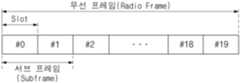
도 5 및 도 6은 본 개시에 적용되는 무선 프레임의 구조를 개략적으로 나타낸 것이다.Figures 5 and 6 schematically illustrate the structure of a wireless frame applied to the present disclosure.
도 5 및 도 6을 참조하면, 하나의 무선 프레임(radio frame)은 10개의 서브프레임(subframe)을 포함하고, 하나의 서브프레임은 2개의 연속적인(consecutive) 슬롯(slot)을 포함한다. 무선 프레임에서 전송 제어를 위한 기본 시간(길이) 단위를 전송 시간 구간(Transmission Time Interval: TTI)라 한다. TTI는 1ms일 수 있다. 한 서브프레임(1 subframe)의 길이는 1ms 이고, 한 슬롯(1 slot)의 길이는 0.5ms일 수 있다.Referring to FIGS. 5 and 6, one radio frame includes 10 subframes, and one subframe includes two consecutive slots. The basic time (length) unit for transmission control in a radio frame is called a transmission time interval (TTI). The TTI can be 1 ms. The length of one subframe can be 1 ms, and the length of one slot can be 0.5 ms.
한 슬롯은 시간 영역에서 복수의 심볼(symbol)들을 포함할 수 있다. 예컨대, 하향링크(Downlink, DL)에서 OFDMA(Orthogonal Frequency Division Multiple Access)를 사용하는 무선 시스템의 경우에 상기 심볼은 OFDM(Orthogonal Frequency Division Multiplexing) 심볼일 수 있으며, 상향링크(Uplink, UL)에서 SC-FDMA(Single Carrier-Frequency Division Multiple Access)를 사용하는 무선 시스템의 경우에 상기 심볼은 SC-FDMA(Single Carrier-Frequency Division Multiple Access) 심볼일 수 있다. 한편, 시간 영역의 심볼 구간(symbol period)에 대한 표현이 다중 접속 방식이나 명칭에 의해 제한되는 것은 아니다.A slot may include multiple symbols in the time domain. For example, in the case of a wireless system using OFDMA (Orthogonal Frequency Division Multiple Access) in the downlink (DL), the symbol may be an OFDM (Orthogonal Frequency Division Multiplexing) symbol, and in the case of a wireless system using SC-FDMA (Single Carrier-Frequency Division Multiple Access) in the uplink (UL), the symbol may be an SC-FDMA (Single Carrier-Frequency Division Multiple Access) symbol. Meanwhile, the expression of a symbol period in the time domain is not limited by a multiple access method or name.
하나의 슬롯에 포함되는 심볼의 개수는 CP(Cyclic Prefix)의 길이에 따라 달라질 수 있다. 예컨대, 일반(normal) CP인 경우에 1 슬롯은 7개의 심볼을 포함하고, 확장(extended) CP인 경우에 1 슬롯은 6개의 심볼을 포함할 수 있다.The number of symbols included in one slot may vary depending on the length of the CP (Cyclic Prefix). For example, in the case of a normal CP, one slot may include 7 symbols, and in the case of an extended CP, one slot may include 6 symbols.
자원 요소(resource element: RE)는 데이터 채널의 변조 심볼 또는 제어 채널의 변조 심볼 등이 맵핑되는 가장 작은 시간-주파수 단위를 나타낸다. 자원 블록(Resource Block, RB)은 자원 할당 단위로서, 주파수 축으로 180kHz, 시간 축으로 1 슬롯(slot)에 해당하는 시간-주파수 자원을 포함한다. 한편, 자원 블록 쌍(resource block pair: PBR)은 시간 축에서 연속된 2개의 슬롯을 포함하는 자원 단위를 의미한다.A resource element (RE) represents the smallest time-frequency unit to which a modulation symbol of a data channel or a modulation symbol of a control channel is mapped. A resource block (RB) is a resource allocation unit and includes time-frequency resources corresponding to 180 kHz in the frequency axis and 1 slot in the time axis. Meanwhile, a resource block pair (PBR) means a resource unit that includes two consecutive slots in the time axis.
물리 계층에서 여러 물리채널들이 사용될 수 있으며, 상기 물리채널들은 상기 무선 프레임에 맵핑되어 전송될 수 있다. 하향링크 물리채널로서, PDCCH(Physical Downlink Control Channel)/EPDCCH(Enhanced PDCCH)는 단말에게 PCH(Paging Channel)와 DL-SCH(Downlink Shared Channel)의 자원 할당 및 DL-SCH와 관련된 HARQ(Hybrid Automatic Repeat Request) 정보를 알려준다. PDCCH/EPDCCH는 단말에게 상향링크 전송의 자원 할당을 알려주는 상향링크 그랜트(uplink grant)를 나를 수 있다. PDCCH와 EPDCCH는 맵핑되는 자원 영역에서 차이가 있다. PDSCH(Physical Downlink Shared Channel)에는 DL-SCH가 맵핑된다. PCFICH(Physical Control Format Indicator Channel)는 단말에게 PDCCH에 사용되는 OFDM 심벌의 수를 알려주고, 매 서브프레임마다 전송된다. PHICH(Physical Hybrid ARQ Indicator Channel)는 하향링크 채널로서, 상향링크 전송의 응답인 HARQ(Hybrid Automatic Repeat reQuest) ACK(Acknowledgement)/NACK(Non-acknowledgement) 신호를 나른다. HARQ ACK/NACK 신호는 HARQ-ACK 신호라고 불릴 수 있다.In the physical layer, several physical channels can be used, and the physical channels can be mapped to the radio frame and transmitted. As a downlink physical channel, the Physical Downlink Control Channel (PDCCH)/Enhanced PDCCH (EPDCCH) informs the UE of resource allocation of the PCH (Paging Channel) and the DL-SCH (Downlink Shared Channel) and HARQ (Hybrid Automatic Repeat Request) information related to the DL-SCH. The PDCCH/EPDCCH can carry an uplink grant that informs the UE of resource allocation of uplink transmission. The PDCCH and EPDCCH have differences in the resource areas to which they are mapped. The DL-SCH is mapped to the PDSCH (Physical Downlink Shared Channel). The Physical Control Format Indicator Channel (PCFICH) informs the UE of the number of OFDM symbols used for the PDCCH, and is transmitted in every subframe. PHICH (Physical Hybrid ARQ Indicator Channel) is a downlink channel that carries HARQ (Hybrid Automatic Repeat reQuest) ACK (Acknowledgement)/NACK (Non-acknowledgement) signals, which are responses to uplink transmissions. HARQ ACK/NACK signals can be called HARQ-ACK signals.
상향링크 물리채널로서, PRACH(Physical Random Access Channel)는 랜덤 액세스 프리앰블을 나른다. PUCCH(Physical Upnlink Control Channel)는 하향링크 전송의 응답인 HARQ-ACK, 하향링크 채널 상태를 나타내는 채널 상태 정보(channel status information, CSI) 예컨대, CQI(Channel Quality Indicator), PMI(precoding matrix index), PTI(precoding type indicator), RI(rank indicator) 등과 같은 상향링크 제어 정보를 나른다. PUSCH(Physical Uplink Shared Channel)은 UL-SCH(Uplink Shared Channel)을 나른다.As an uplink physical channel, the Physical Random Access Channel (PRACH) carries a random access preamble. The Physical Upnlink Control Channel (PUCCH) carries uplink control information such as HARQ-ACK, which is a response to downlink transmission, and channel status information (CSI) indicating the downlink channel status, such as the Channel Quality Indicator (CQI), precoding matrix index (PMI), precoding type indicator (PTI), and rank indicator (RI). The Physical Uplink Shared Channel (PUSCH) carries the Uplink Shared Channel (UL-SCH).
PUSCH 상으로 상향링크 데이터가 전송될 수 있으며, 상기 상향링크 데이터는 TTI(Transmission Time Interval) 동안 전송되는 UL-SCH를 위한 데이터 블록인 전송 블록(Transport Block, TB)일 수 있다. 상기 전송 블록은 사용자 데이터를 포함할 수 있다. 또는, 상향링크 데이터는 다중화된(multiplexed) 데이터일 수 있다. 다중화된 데이터는 UL-SCH를 위한 전송 블록과 상향링크 제어 정보가 다중화된 것일 수 있다. 즉, 상향링크로 전송되어야 하는 사용자 데이터가 있는 경우 상향링크 제어 정보는 상기 사용자 데이터와 함께 다중화되어 PUSCH를 통하여 전송될 수 있다.Uplink data may be transmitted on a PUSCH, and the uplink data may be a transport block (TB), which is a data block for an UL-SCH transmitted during a TTI (Transmission Time Interval). The transport block may include user data. Alternatively, the uplink data may be multiplexed data. The multiplexed data may be a transport block for an UL-SCH and uplink control information multiplexed. That is, when there is user data to be transmitted on an uplink, the uplink control information may be multiplexed with the user data and transmitted through a PUSCH.
CIoT는 셀룰러(cellular) IoT를 의미하며, NB-IoT(narrow band IoT), NB-CIoT, NB-LTE로 호칭될 수도 있다.CIoT stands for Cellular IoT and can also be called NB-IoT (narrow band IoT), NB-CIoT, and NB-LTE.
이하에서는, NB-IoT 시스템을 일 예로써 설명할 것이나, 본 개시의 실시예가 반드시 NB-IoT 시스템에 한정적으로 적용되는 것은 아니며, 5G(5-generation) eMBB(enhanced mobile broadband) 시스템이나 mMTC(massive MTC) 시스템에도 적용될 수도 있음은 물론이다. 또한, 레거시 시스템으로써 LTE 시스템을 설명할 것이나, 본 개시가 반드시 LTE 시스템에 한정적으로 적용되는 것은 아니며, 기타 셀룰러 시스템에도 적용될 수 있음은 물론이다.Hereinafter, the NB-IoT system will be described as an example, but the embodiments of the present disclosure are not necessarily limited to the NB-IoT system, and may of course be applied to a 5G (5-generation) eMBB (enhanced mobile broadband) system or a mMTC (massive MTC) system. In addition, the LTE system will be described as a legacy system, but the present disclosure is not necessarily limited to the LTE system, and may of course be applied to other cellular systems.
A. NB- IoT 시스템 배치 시나리오A. NB-IoT System Deployment Scenario
NB-IoT 시스템은 협대역폭(narrow bandwidth)을 점유한다. 예를 들어, NB-IoT 시스템은 200kHz (또는 180kHz)의 최소 시스템 대역폭을 다운링크(downlink; DL) 및 업링크(uplink; UL) 모두에서 사용할 수 있다. 협대역폭을 점유한다는 특징으로 인해, 상기 NB-IoT 시스템은 독립(standalone) 배치되거나, 레거시 셀룰러 시스템(예를 들어, LTE 시스템)의 가드밴드(guard-band) 내에서 배치되거나, 또는 상기 레거시 셀룰러 시스템의 시스템 대역폭 내에서 배치될 수 있다.The NB-IoT system occupies a narrow bandwidth. For example, the NB-IoT system can use a minimum system bandwidth of 200 kHz (or 180 kHz) in both the downlink (DL) and uplink (UL). Because of the narrow bandwidth occupancy, the NB-IoT system can be deployed standalone, within the guard-band of a legacy cellular system (e.g., an LTE system), or within the system bandwidth of the legacy cellular system.
도 7은 NB-IoT 시스템의 다양한 배치 시나리오를 예시하는 도면이다.Figure 7 is a diagram illustrating various deployment scenarios of an NB-IoT system.
도 7의 (a)를 참고하면, NB-IoT 시스템은 독립 모드(standalone mode)로 배치될 수 있는데, 예를 들어, 200 kHz 대역폭을 갖는 GSM 캐리어(700)를 리파밍(re-farming; 다른 통신 서비스로 재활용)하여 독립 모드로 배치될 수 있다.Referring to (a) of Fig. 7, the NB-IoT system can be deployed in a standalone mode, for example, by re-farming (reusing for other communication services) a GSM carrier (700) having a bandwidth of 200 kHz.
도 7의 (b)를 참고하면, LTE 시스템은 (시스템 대역폭에 따라서) 200kHz 내지 2MHz의 가드밴드를 가질 수 있으며, NB-IoT 시스템은 LTE 시스템의 가드밴드 영역(702)에 배치될 수 있는데, 상기 가드밴드 영역(702)에 배치되는 NB-IoT 시스템의 동작 모드를 가드밴드 모드(guard-band mode)라고 호칭할 수 있다.Referring to (b) of FIG. 7, the LTE system may have a guard band of 200 kHz to 2 MHz (depending on the system bandwidth), and the NB-IoT system may be deployed in the guard band region (702) of the LTE system. The operation mode of the NB-IoT system deployed in the guard band region (702) may be referred to as a guard band mode.
도 7의 (c)를 참고하면, LTE 시스템의 물리 자원 블록(PRB; physical resource block) 대역폭은 180 kHz 이므로, NB-IoT 시스템은 전체 대역폭 내의 임의 PRB(704) 내에 배치될 수 있는데, LTE 대역폭 내의 임의의 PRB(704) 내에 배치되는 NB-IoT 시스템의 동작 모드를 인밴드 모드(in-band mode)라고 호칭할 수 있다.Referring to (c) of FIG. 7, since the physical resource block (PRB) bandwidth of the LTE system is 180 kHz, the NB-IoT system can be placed within any PRB (704) within the entire bandwidth, and the operation mode of the NB-IoT system placed within any PRB (704) within the LTE bandwidth can be called in-band mode.
또한, 스케일러블(: 조정 가능한) 용량을 제공하기 위해 NB-IoT 시스템에게 다수의 PRB를 할당하는 것도 가능한데, 이것은 자원 활용도 및 주파수 다이버시티(diversity) 관점에서 유익하다. 다수의 PRB들에 걸친 주파수 호핑(hopping)의 적용은 간섭 랜덤화(interference randomization)를 더 제공하고, 충분히 분리된 PRB와 증가된 다이버시티 이득을 제공할 수 있다. 다수의 PRB를 이용하여 동작하는 것은 특히 인밴드 모드에서 바람직하다. 왜냐하면, NB-IoT 시스템의 다운링크 전송 전력은 레거시(legacy) 시스템(예를 들어, LTE 시스템)과 공유될 수 있고, 레거시 제어 채널(예를 들어, PDCCH(physical downlink control channel) 또는 기준 신호(예를 들어, CRS(cell-specific reference signal))에 의해 점유되는 자원은 NB-IoT에 의해 사용되지 않을 것이기 때문이다.Additionally, it is possible to allocate multiple PRBs to an NB-IoT system to provide scalable capacity, which is beneficial from a resource utilization and frequency diversity perspective. The application of frequency hopping across multiple PRBs can provide further interference randomization and provide sufficiently separated PRBs and increased diversity gain. Operating with multiple PRBs is particularly desirable in the in-band mode, because the downlink transmit power of the NB-IoT system may be shared with legacy systems (e.g., LTE systems) and resources occupied by legacy control channels (e.g., physical downlink control channel (PDCCH) or reference signals (e.g., cell-specific reference signal (CRS)) will not be used by NB-IoT.
B. NB- IoT 시스템 시간/주파수 자원 구조B. NB-IoT System Time/Frequency Resource Structure
도 8은 NB-IoT 시스템에서 하나의 서브프레임에 해당하는 자원 그리드를 예시하는 도면이다.Figure 8 is a diagram illustrating a resource grid corresponding to one subframe in an NB-IoT system.
인밴드 모드를 지원하는 NB-IoT 시스템은 레거시 LTE 시스템과의 공존과 호환성을 고려하여 설계되어야 한다. 레거시 LTE 시스템에 대한 부정적 영향을 피하기 위해, LTE 파라메터(예를 들어, 파형(waveform), 서브캐리어 스페이싱(spacing)과 같은)가 NB-IoT 시스템을 위해 가능한 많이 재사용될 수 있다. 도 8에서 NB-IoT 시스템의 하나의 서브프레임(subframe) 동안에 1개의 PRB의 자원 그리드(resource grid)가 예시된다. 도 8에서 예시되듯이, NB-IoT 시스템의 자원 그리드는 LTE 시스템의 자원 그리드와 동일할 수 있다. 도 8의 (a)는 노멀 CP(normal cyclic prefix)의 경우에 자원 그리드를 예시하고, 도 8의 (b)는 확장 CP(extended cyclic prefix)의 경우에 자원 그리드를 예시한다.NB-IoT system supporting in-band mode should be designed considering coexistence and compatibility with legacy LTE system. To avoid negative impact on legacy LTE system, LTE parameters (e.g., waveform, subcarrier spacing, etc.) can be reused for NB-IoT system as much as possible. In Fig. 8, resource grid of one PRB during one subframe of NB-IoT system is illustrated. As illustrated in Fig. 8, resource grid of NB-IoT system can be same as resource grid of LTE system. Fig. 8(a) illustrates resource grid in case of normal cyclic prefix (CP), and Fig. 8(b) illustrates resource grid in case of extended cyclic prefix (CP).
도 9는 NB-IoT 시스템에서 L-서브프레임의 구조를 예시하는 도면이다.Figure 9 is a diagram illustrating the structure of an L-subframe in an NB-IoT system.
NB-IoT 시스템을 위한 보다 자세한 시간 도메인 구조가 도 9에 예시된다. 단지 1개의 PRB만 사용되는 경우에, 보다 긴(longer) 서브프레임 유닛(900)(예를 들어, 4개의 서브프레임(920)(4ms)을 포함하는 L-서브프레임)이 최소 스케줄링 단위로써 정의될 수 있다. L-서브프레임(900)보다 짧은 스케줄링 유닛이 필요하다면, 보다 긴(longer) 슬롯(910)(예를 들어, 2ms의 L-슬롯)이 고려될 수 있다.A more detailed time domain structure for an NB-IoT system is illustrated in Fig. 9. When only one PRB is used, a longer subframe unit (900) (e.g., an L-subframe including four subframes (920) (4 ms)) can be defined as the minimum scheduling unit. If a scheduling unit shorter than an L-subframe (900) is required, a longer slot (910) (e.g., an L-slot of 2 ms) can be considered.
도 10은 NB-IoT 시스템에서 L-슈퍼프레임의 구조를 예시하는 도면이다.Figure 10 is a diagram illustrating the structure of an L-superframe in an NB-IoT system.
유사하게, 10개의 L-서브프레임(1000)을 포함하여 40ms의 기간(duration)을 갖는 L-프레임(1010)이 정의될 수 있다. L-프레임(1010)의 기간은 예를 들어, LTE 시스템에서 PBCH(physical broadcast channel) 전송 시간 구간(TTI; transmission time interval)에 맞춰질 수 있는데, 4 반복의 PBCH 하나는 40ms 동안에 전송된다. 하나의 L-슈퍼프레임(1020)은 32개의 L-프레임(1010)을 포함하고, 1280ms의 기간을 가질 수 있다.Similarly, an L-frame (1010) having a duration of 40 ms can be defined, comprising 10 L-subframes (1000). The duration of the L-frame (1010) can be, for example, aligned with a physical broadcast channel (PBCH) transmission time interval (TTI) in an LTE system, where one PBCH of 4 repetitions is transmitted for 40 ms. One L-superframe (1020) can comprise 32 L-frames (1010) and have a duration of 1280 ms.
도 11은 NB-IoT 시스템에서 다운링크 시간 도메인 구조를 예시하는 도면이다.Figure 11 is a diagram illustrating the downlink time domain structure in an NB-IoT system.
도 11을 참고하면, 전송 채널들은 TDM(time division multiplexing) 방식으로 정렬된다. 동기 시퀀스(synchronization sequence) 및 브로드캐스트 정보(예를 들어, MIB(master information block)와 같은 시스템 정보)가 L-슈퍼프레임(500)의 시점(beginning)(502)에 함께 전송될 수 있다. 일반적으로, 동기 시퀀스는 PSS(primary synchronization sequence) 및 SSS(secondary synchronization sequence)를 포함할 수 있다. 상기 MIB는 제한된 양의 시스템 정보를 포함할 수 있다. 상기 MIB에 포함되지 못한 나머지 시스템 정보는 SIB(system information block)(504)에서 전송될 수 있다. 커버리지 요구사항(requirement)에 따라서 상기 MIB(502) 및 SIB(504) 프레임은 반복적으로 전송될 수 있다.Referring to FIG. 11, transmission channels are arranged in a TDM (time division multiplexing) manner. A synchronization sequence and broadcast information (e.g., system information such as a master information block (MIB)) may be transmitted together at the beginning (502) of an L-superframe (500). Typically, the synchronization sequence may include a primary synchronization sequence (PSS) and a secondary synchronization sequence (SSS). The MIB may include a limited amount of system information. The remaining system information not included in the MIB may be transmitted in a system information block (SIB) (504). Depending on coverage requirements, the MIB (502) and SIB (504) frames may be transmitted repeatedly.
도 12는 NB-IoT 시스템에서 PSS/SSS 전송을 예시하는 도면이다.Figure 12 is a diagram illustrating PSS/SSS transmission in an NB-IoT system.
NB-IoT 시스템에서 한 개의 PRB만이 사용되는 경우, 동기 시퀀스의 탐지 성능을 높이기 위해 PSS 및/또는 SSS는 하나의 서브프레임에서 반복(전송)될 수 있다. LTE 시스템의 경우와 유사하게, NB-IoT 디바이스는 PSS/SSS를 탐지함으로써 기본(basic) 시스템 정보 예를 들어, 프레임 타이밍, CP 길이(normal CP 또는 extended CP), FDD(frequency division duplex) 모드인지 TDD(time division duplex) 모드인지 여부, 및 셀 ID 등을 획득할 수 있다. 도 12에서와 같이, PSS(600)와 SSS(602)를 서브프레임(610) 내의 서로 다른 심볼에 맞춤으로써, CP 길이와 FDD/TDD 모드는 성공적 PSS/SSS 탐지 후 유도될 수 있다. 도 12의 (a)는 FDD 모드와 노멀 CP를 예시하고, 도 12의 (b)는 FDD 모드와 확장 CP를 예시하고, 도 12의 (c)는 TDD 모드와 노멀 CP를 예시하고, 도 12의 (d)는 TDD 모드와 확장 CP를 예시한다.When only one PRB is used in an NB-IoT system, the PSS and/or SSS can be repeated (transmitted) in one subframe to improve the detection performance of the synchronization sequence. Similar to the LTE system, the NB-IoT device can obtain basic system information, such as frame timing, CP length (normal CP or extended CP), whether it is frequency division duplex (FDD) mode or time division duplex (TDD) mode, and cell ID, by detecting the PSS/SSS. As shown in FIG. 12, by aligning the PSS (600) and the SSS (602) to different symbols within the subframe (610), the CP length and the FDD/TDD mode can be derived after successful PSS/SSS detection. Fig. 12 (a) exemplifies FDD mode and normal CP, Fig. 12 (b) exemplifies FDD mode and extended CP, Fig. 12 (c) exemplifies TDD mode and normal CP, and Fig. 12 (d) exemplifies TDD mode and extended CP.
NB-IoT 인밴드 모드에서, PSS/SSS는 기준 신호 점유 심볼(예를 들어, CRS(630) 등)과 제어 채널(예를 들어, PDCCH(620)) 점유 심볼은 사용을 피할 필요가 있다.In NB-IoT in-band mode, PSS/SSS need to avoid using reference signal occupied symbols (e.g., CRS (630) etc.) and control channel (e.g., PDCCH (620)) occupied symbols.
도 13은 NB-IoT 시스템에서 PSS 전송의 일 예를 도시한다.Figure 13 illustrates an example of PSS transmission in an NB-IoT system.
도 13의 (a)을 참고하면, PSS 전송을 위한 두 개의 연속적 심볼을 배열(arranging)함으로써, PSS 탐지 성능은 향상될 수 있다.Referring to (a) of Fig. 13, PSS detection performance can be improved by arranging two consecutive symbols for PSS transmission.
도 13의 (b)를 참고하면, PSS 신호는 직접적으로 반복되기 때문에, PSS 심볼(1300)의 'A' 부분(1302)은 다음 PSS 심볼(1310)을 위한 가상(virtual) CP로써 고려될 수 있다. 이 경우, PSS는 어떠한 CP 길이가 사용되는지 여부(즉, normal CP 인지 extended CP 인지 여부)와 관계 없이 탐지될 수 있다. 또한, 심볼 레벨의 정정(correction)이 가능해지고, 이러한 심볼 레벨 정정은 수신측의 PSS 탐지 복잡도를 줄일 수 있게 한다.Referring to (b) of Fig. 13, since the PSS signal is directly repeated, the 'A' portion (1302) of the PSS symbol (1300) can be considered as a virtual CP for the next PSS symbol (1310). In this case, the PSS can be detected regardless of whether a CP length is used (i.e., whether it is a normal CP or an extended CP). In addition, symbol-level correction becomes possible, and this symbol-level correction can reduce the complexity of PSS detection at the receiver.
도 14는 NB-IoT 시스템에서 PBCH 전송의 일 예를 도시한다.Figure 14 illustrates an example of PBCH transmission in an NB-IoT system.
도 14의 (a)는 인밴드 모드에서 노멀 CP의 RE(resource element; 자원 요소) 매핑을 예시하고, 도 14의 (b)는 인밴드 모드에서 확장 CP의 RE 매핑을 예시하고, 도 14의 (c)는 가드 밴드/독립 모드에서 노멀 CP의 RE 매핑을 예시하고, 도 14의 (d)는 가드 밴드/독립 모드 에서 확장 CP의 RE 매핑을 예시한다. PBCH(MIB 및/또는 SIB)와 같은 시스템 정보 및 PSS/SSS는 같은 서브프레임에서 전송될 수 있다. PSS(800)와 SSS(802)가 서브프레임 내의 모든 심볼을 사용하지는 않을 것이기 때문이다. 그리고, PSS(800)와 SSS(802) 신호는 상기 PBCH 디코딩을 위한 채널 추정에 사용될 수 있다.Fig. 14(a) illustrates RE (resource element) mapping of normal CP in in-band mode, Fig. 14(b) illustrates RE mapping of extended CP in in-band mode, Fig. 14(c) illustrates RE mapping of normal CP in guard band/independent mode, and Fig. 14(d) illustrates RE mapping of extended CP in guard band/independent mode. System information such as PBCH (MIB and/or SIB) and PSS/SSS can be transmitted in the same subframe. This is because PSS (800) and SSS (802) will not use all symbols in a subframe. And, PSS (800) and SSS (802) signals can be used for channel estimation for the PBCH decoding.
도 14의 (a), 14의 (b)을 참고하면, 인밴드 모드에서, 서브프레임 내의 PSS(800)/SSS(802)에 의해 점유되지 않은 RE (예를 들어, 806)는 PBCH 전송에 사용될 수 있다. 그러나, 인밴드 모드에서 CRS 점유 RE(예를 들어, 804)는 PBCH를 위한 RE 매핑에서 사용되지 않을 수 있다.Referring to (a) and (b) of FIG. 14, in the in-band mode, REs (e.g., 806) not occupied by PSS (800)/SSS (802) within a subframe can be used for PBCH transmission. However, in the in-band mode, REs occupied by CRS (e.g., 804) may not be used in RE mapping for PBCH.
도 14의 (c), 14의 (d)를 참고하면, 가드밴드 모드 또는 독립 모드에서는, CRS 가 전송되지 않으므로, PSS/SSS 심볼을 제외한 모든 RE가 PBCH를 위해 사용될 수 있을 것이다.Referring to (c) and (d) of FIG. 14, in guardband mode or independent mode, since CRS is not transmitted, all REs except PSS/SSS symbols can be used for PBCH.
NB-IoT 인밴드 모드에서, NB-IoT 시스템과 LTE 시스템은 다운링크 전송에서 기지국의 전력을 공유할 수 있다. 임의 신호 또는 전송 채널(예를 들어, PSS/SSS, MIB, SIB, 또는 PDCCH)의 전력 부스팅(boosting)이 인밴드 모드 NB-IoT 시스템의 커버리지 성능 향상을 위해 고려될 수 있다.In NB-IoT in-band mode, the NB-IoT system and the LTE system can share the power of the base station in downlink transmission. Power boosting of arbitrary signals or transmission channels (e.g., PSS/SSS, MIB, SIB, or PDCCH) can be considered to improve the coverage performance of the in-band mode NB-IoT system.
도 15는 레거시 시스템의 PSS/SSS/MIB와 충돌을 피하기 위한 NB-IoT 시스템의 PSS/SSS/MIB 전송을 시간 도메인에서 예시하는 도면이다.Figure 15 is a diagram illustrating PSS/SSS/MIB transmission of an NB-IoT system in the time domain to avoid collision with PSS/SSS/MIB of a legacy system.
레거시 시스템의 PSS/SSS/MIB 전송과 충돌을 가능한 피하면서 NB-IoT PSS/SSS/MIB 전송을 설계하는 것도 가능하다. 예를 들어, 도 15에 예시되는 것처럼, 시간 도메인에서 충돌을 회피하기 위하여, NB-IoT PSS/SSS/MIB를 전송하는 S&B 서브프레임(1500) 및 SIB 서브프레임(1502)은 적절한 방식으로 분산될 수 있다. 대안적으로, 상기 NB-IoT PSS/SSS/MIB 전송 서브프레임(1500)은 LTE PSS/SSS/MIB 심볼과의 충돌을 가능한 회피하도록 설계될 수 있다. 예를 들어, PSS/SSS는 상기 서브프레임(1500) 내의 마지막 심볼에 위치시킴으로써 LTE 시스템의 경우와 다르게 설계될 수 있다.It is also possible to design NB-IoT PSS/SSS/MIB transmission to avoid collisions with legacy system PSS/SSS/MIB transmissions, if possible. For example, as illustrated in FIG. 15, in order to avoid collisions in the time domain, the S&B subframe (1500) and the SIB subframe (1502) transmitting NB-IoT PSS/SSS/MIB can be distributed in an appropriate manner. Alternatively, the NB-IoT PSS/SSS/MIB transmission subframe (1500) can be designed to avoid collisions with LTE PSS/SSS/MIB symbols, if possible. For example, the PSS/SSS can be designed differently from the case of LTE systems by positioning it in the last symbol in the subframe (1500).
IoT(Internet of Things) 서비스가 활성화됨에 따라 IoT 단말/디바이스의 밀도가 높아지고 있으며, 하나의 IoT 기지국에서 더 많은 수의 단말을 지원하기 위한 방법들이 연구되고 있다. IoT 서비스를 위해 사용되는 주파수는 면허대역과 비면허대역으로 구분될 수 있다. 비면허대역에서는 무선LAN, 무선PAN 등의 시스템을 이용하여 IoT 서비스를 할 수 있으며, IoT 전용 표준으로서 IEEE802.16ah, IEEE802.15.4g, IEEE802.15.4k 등 다양한 무선LAN (Local Area Network), 무선PAN (Personal Area Network) 표준이 개발되었고 LoRa, Sigfox, Weightless 등 다양한 비표준 무선통신 시스템도 개발되었다. 또한, 3GPP 표준(TS 36.211/TS36.212/TS36.213/TS36.214/TS36.215/TS36.301/TS36.321/TS36.3331 등)에서도 IoT 시스템을 다루고 있다.As IoT (Internet of Things) services are activated, the density of IoT terminals/devices is increasing, and methods to support a greater number of terminals from a single IoT base station are being studied. The frequencies used for IoT services can be divided into licensed and unlicensed bands. In unlicensed bands, IoT services can be provided using systems such as wireless LAN and wireless PAN, and various wireless LAN (Local Area Network) and wireless PAN (Personal Area Network) standards such as IEEE802.16ah, IEEE802.15.4g, and IEEE802.15.4k have been developed as IoT-specific standards, and various non-standard wireless communication systems such as LoRa, Sigfox, and Weightless have also been developed. In addition, 3GPP standards (TS 36.211/TS36.212/TS36.213/TS36.214/TS36.215/TS36.301/TS36.321/TS36.3331, etc.) also deal with IoT systems.
무선통신 시스템 상에서 비면허 대역을 이용하여 IoT 서비스가 제공될 때, IoT 통신을 수행하는 단말의 밀도가 매우 높은 경우에는 IoT 기지국(액세스 포인트)은 여러 개의 주파수 채널을 사용할 필요가 있다. 이 때, 여러 개의 주파수 채널을 사용하기 위해, 여러 개의 모듈을 안테나를 공유하여 사용하거나, 또는 각 채널 별로 별도의 안테나가 사용되더라도, 공간적인 제약으로 인해 안테나들이 가까이 위치하는 것이 편리할 수 있다. 그러나, 시간 축과는 달리 주파수 축 채널은 완전히 독립적이지 않아서 채널 간의 간섭이 발생할 수 있다. 기지국이 단말로부터 수신하는 신호의 수신 신호 전력은 기지국이 단말로 전송하는 신호의 송신 신호 전력에 비해서 크기가 매우 작다. 따라서, 인접한 채널들 간의 간섭으로 인해, 인접한 주파수 채널에 대해서 각각 사용되는 여러 개의 모듈 중에서, 하나의 모듈이 신호를 송신을 하는 경우, 동일 위치에 존재하는 다른 모듈은 신호를 수신하는 것이 가능하지 않을 수 있다. 즉, 신호를 송신하는 모듈에서의 송신 신호 전력이 신호를 수신하는 모듈에서의 수신 신호 전력보다 압도적으로 크게되어, 신호를 수신하는 모듈에서의 신호 검출이 불가능할 수 있다.When IoT services are provided using unlicensed bands on a wireless communication system, if the density of terminals performing IoT communication is very high, the IoT base station (access point) needs to use multiple frequency channels. At this time, in order to use multiple frequency channels, multiple modules may share antennas or, even if separate antennas are used for each channel, it may be convenient for the antennas to be located close together due to spatial constraints. However, unlike the time axis, the frequency axis channels are not completely independent, so interference between channels may occur. The reception signal power of the signal that the base station receives from the terminal is very small compared to the transmission signal power of the signal that the base station transmits to the terminal. Therefore, due to interference between adjacent channels, when one module among multiple modules used for each adjacent frequency channel transmits a signal, other modules present at the same location may not be able to receive the signal. In other words, the transmission signal power of the module transmitting the signal may be overwhelmingly greater than the reception signal power of the module receiving the signal, so that signal detection may not be possible in the module receiving the signal.
도 16은 IoT 기지국이 여러 개의 채널을 통해 단말들과 신호를 송수신하는 예시를 나타낸 도이다. 보다 구체적으로, 도 16은 IoT 기지국이 여러 개의 채널을 통해 단말들로부터 신호를 수신하는 경우, 인접한 채널들 간의 간섭으로 인해 단말들로부터의 신호 수신에 실패하는 경우를 나타낸다. 도 16을 참조하면, 4대의 단말과 기지국이 각 단말들에 대하여 할당된 4개의 채널(1610 내지 1640)을 통해서 신호를 송수신한다. 기지국이 4대의 단말들 중 적어도 하나의 단말들로부터 할당된 주파수 채널을 통해 전송한 상향링크 패킷/신호를 수신할 때, 상기 기지국이 상기 단말들 중 다른 적어도 하나의 단말에게 할당된 다른 채널을 통해 하향링크 패킷/신호를 전송하는 경우, 상기 기지국이 상향링크 패킷/신호를 수신하는 채널과 상기 기지국이 하향링크 패킷/신호를 전송하는 채널 간의 간섭으로 인해, 상기 기지국은 상향링크 패킷/신호 수신에 실패할 수 있다. 도 16의 4대의 단말과 기지국 간의 신호 송수신이 이루어지는 경우에 대한 도시는 하나의 예시에 불과할 뿐, 본 개시에서 제안하는 방법은 적어도 하나의 단말과 기지국 간의 신호 송수신이 이루어 지는 경우에 확장되어 적용될 수 있음은 당연하다.FIG. 16 is a diagram showing an example of an IoT base station transmitting and receiving signals with terminals through multiple channels. More specifically, FIG. 16 shows a case where, when an IoT base station receives signals from terminals through multiple channels, reception of signals from terminals fails due to interference between adjacent channels. Referring to FIG. 16, four terminals and a base station transmit and receive signals through four channels (1610 to 1640) assigned to each of the terminals. When the base station receives an uplink packet/signal transmitted through a frequency channel assigned from at least one of the four terminals, when the base station transmits a downlink packet/signal through another channel assigned to at least one other terminal among the terminals, the base station may fail to receive the uplink packet/signal due to interference between the channel through which the base station receives the uplink packet/signal and the channel through which the base station transmits the downlink packet/signal. The case where signal transmission and reception between four terminals and a base station in FIG. 16 is performed is only one example, and it is obvious that the method proposed in the present disclosure can be expanded and applied to cases where signal transmission and reception are performed between at least one terminal and a base station.
도 16에서 설명된 인접 채널들 간의 간섭을 완화시키기 위한 방법으로는, 매우 샤프(sharp)한 필터를 사용하여 인접 채널 간섭을 제거하는 방법, 각 주파수 채널의 간격을 충분히 떨어뜨리는 방법, 주파수 채널마다 다른 안테나를 사용하고, 안테나들을 서로 공간적으로 충분히 떨어뜨리는 방법 등이 있을 수 있다. 그러나, 매우 샤프한 필터를 사용하는 방법의 경우, 비용이 증가의 문제가 존재하고, 각 주파수 채널의 간격을 충분히 떨어뜨리는 방법의 경우, 사용되지 못하는 주파수 채널이 많아지게 됨으로 인해, 많은 수의 IoT 디바이스를 수용하기 어려우며, 주파수 자원 낭비의 문제가 존재한다. 또한, 안테나들을 멀리 떨어뜨려 놓는 방법은 IoT 시스템 설치를 어렵게 만드는 문제가 존재한다. 따라서, 비용증가, 주파수 자원 낭비, IoT 시스템 설치가 어려운 문제 없이 인접한 채널들 간의 간섭을 제거하기 위한 송수신 방법이 필요하다.Methods for mitigating interference between adjacent channels described in FIG. 16 may include a method of removing interference between adjacent channels using a very sharp filter, a method of sufficiently spacing out each frequency channel, a method of using different antennas for each frequency channel and sufficiently spacing out the antennas from each other spatially, etc. However, in the case of a method of using a very sharp filter, there is a problem of increased cost, and in the case of a method of sufficiently spacing out each frequency channel, since many unused frequency channels become available, it is difficult to accommodate a large number of IoT devices and there is a problem of wasting frequency resources. In addition, a method of spacing out antennas far apart makes it difficult to install an IoT system. Therefore, a transmission/reception method for removing interference between adjacent channels without increasing cost, wasting frequency resources, or making it difficult to install an IoT system is needed.
위에서 설명한 방법 외에도, 인접 채널 간섭을 완화시키는 방법으로 TDD(Time Division Duplexing) 방식을 이용하는 방법이 있을 수 있다. 도 17은 IoT 기지국이 여러 개의 채널을 통해 단말들과 신호를 송수신하는 또 다른 예시를 나타낸 도이다. 보다 구체적으로, 도 17은 IoT 기지국이 TDD(Time Division Duplexing) 방식을 사용하여 여러 개의 채널을 통해 단말들로부터 신호를 수신하는 경우에 관한 것이다.In addition to the method described above, there may be a method using the TDD (Time Division Duplexing) method as a method for mitigating adjacent channel interference. Fig. 17 is a diagram showing another example in which an IoT base station transmits and receives signals with terminals through multiple channels. More specifically, Fig. 17 relates to a case in which an IoT base station receives signals from terminals through multiple channels using the TDD (Time Division Duplexing) method.
도 17을 참조하면, 4대의 단말과 기지국이 각 단말들에 대하여 할당된 4개의 채널(1710 내지 1740)을 통해서 신호를 송수신한다. 이 때, 기지국-단말들 간의 신호 송수신은 TDD 방식을 통해 수행되며, 시간자원은 상향링크 신호 송수신이 이루어지는 시간 구간과 하향링크 신호 송수신이 이루어지는 시간 구간으로 분리되어 구성될 수 있다. 도 17에서 나타낸 시간자원 구성은 하나의 예시에 불과할 뿐, 본 개시에서 제안하는 방법이 도 17에 도시된 형태로만 동작하지 않음은 물론이다. 도 17의 경우, TDD 방식이 사용되기 때문에, 시간자원이 상향링크 신호 송수신이 이루어지는 시간 구간과 하향링크 신호 송수신이 이루어지는 시간 구간으로 분리되어 구성되어 있으며, 이에 따라 기지국은 상향링크 신호를 수신한 경우, 이에 대한 응답 패킷은 즉시 전송하지 못할 수 있다. 즉, 기지국이 상향링크 신호 송수신이 이루어지는 시간 구간 내에서 이미 상향링크 신호 송수신을 완료하더라도, 상향링크 신호 송수신을 완료한 시점이 상향링크 신호 송수신이 이루어지는 시간 구간이 종료되기 전이라면 기지국은 상향링크 신호에 대한 응답을 전송하기 위해 향링크 신호 송수신이 이루어지는 시간 구간이 시작되는 시점까지 응답 전송을 지연시켜야 한다. 따라서, 기지국의 응답 전송은 기지국의 하향링크 전송이 가능한 시간 구간까지 지연되는 지연 응답(delayed Ack)이 되어야 한다.Referring to FIG. 17, four terminals and a base station transmit and receive signals through four channels (1710 to 1740) allocated to each terminal. At this time, signal transmission and reception between the base station and terminals is performed through the TDD method, and time resources can be configured to be separated into a time section in which uplink signal transmission and reception occur and a time section in which downlink signal transmission and reception occur. The time resource configuration illustrated in FIG. 17 is merely an example, and it goes without saying that the method proposed in the present disclosure does not operate only in the form illustrated in FIG. 17. In the case of FIG. 17, since the TDD method is used, time resources are configured to be separated into a time section in which uplink signal transmission and reception occur and a time section in which downlink signal transmission and reception occur, and accordingly, when the base station receives an uplink signal, it may not immediately transmit a response packet thereto. That is, even if the base station has already completed the uplink signal transmission and reception within the time period in which the uplink signal transmission and reception takes place, if the time period in which the uplink signal transmission and reception is completed is before the end of the time period in which the uplink signal transmission and reception takes place, the base station must delay the response transmission until the time period in which the downlink signal transmission takes place starts in order to transmit a response to the uplink signal. Accordingly, the response transmission of the base station must be a delayed response (delayed Ack) that is delayed until the time period in which the base station can perform downlink transmission.
다만, 이와 같은 기지국의 지연 응답(delayed Ack) 방식은 기존 무선LAN, 무선PAN 표준 규격에 위배되는 것이므로, 새로운 규격이 필요하거나, 규격의 변경이 필요하게 된다. 따라서, 물리계층 및 MAC 계층의 기존 표준 규격을 변경하지 않으면서 인접 채널 간섭을 완화시키기 위한 방법이 필요하다. 도 17의 4대의 단말과 기지국 간의 신호 송수신이 이루어지는 경우에 대한 도시는 하나의 예시에 불과할 뿐, 본 개시에서 제안하는 방법은 적어도 하나의 단말과 기지국 간의 신호 송수신이 이루어 지는 경우에 확장되어 적용될 수 있음은 당연하다.However, since the delayed Ack method of the base station violates the existing wireless LAN and wireless PAN standard specifications, a new standard or a change in the standard is required. Therefore, a method for alleviating adjacent channel interference without changing the existing standard specifications of the physical layer and MAC layer is required. The illustration of the case where signals are transmitted and received between four terminals and the base station in Fig. 17 is only one example, and it is obvious that the method proposed in the present disclosure can be expanded and applied to the case where signals are transmitted and received between at least one terminal and the base station.
이하에서, 본 개시에서 제안하는 무선 통신 시스템에서 신호를 송수신하기 위한 방법에 대해서 구체적으로 설명한다. 본 개시에서 제안하는 방법은 여러 단말이 각각 여러 채널로 신호를 전송할 때, 각 단말들의 채널 간 간섭으로 인한 문제를 해결하기 위한 방법에 관한 것이다. 본 개시에서 제안하는 방법은 IoT 시스템에 적용될 수도 있지만, IoT 시스템 외의 다양한 무선통신 시스템에도 동일/유사하게 적용될 수 있음은 물론이다.Hereinafter, a method for transmitting and receiving a signal in a wireless communication system proposed in the present disclosure will be specifically described. The method proposed in the present disclosure relates to a method for solving a problem caused by interference between channels of each terminal when multiple terminals transmit signals through multiple channels, respectively. The method proposed in the present disclosure may be applied to an IoT system, but it is of course equally/similarly applicable to various wireless communication systems other than the IoT system.
본 개시는 IoT 기지국이 여러 개의 주파수 채널을 사용하여 단말들과 신호를 송수신할 때, 인접 채널 간섭을 완화하기 위한 방법으로 TDD 동작을 하기 위해서 무선통신 시스템의 규격 변경 없이 동작시키기 위하여 패킷의 끝 지점을 맞추는/정렬시키는 방법을 제안한다.The present disclosure proposes a method of aligning/matching the end points of packets to operate TDD operation without changing the standards of a wireless communication system as a method of mitigating adjacent channel interference when an IoT base station transmits and receives signals with terminals using multiple frequency channels.
도 18은 본 개시에서 제안하는 신호 송수신 방법이 수행되는 일 예를 나타낸 도이다. 도 18을 참조하면, 4대의 단말과 기지국이 각 단말들에 대하여 할당된 4개의 채널(1810 내지 1840)을 통해서 신호를 송수신한다. 이 때, 기지국-단말들 간의 신호 송수신은 TDD 방식을 통해 수행되며, 시간자원은 상향링크 신호 송수신이 이루어지는 시간 구간과 하향링크 신호 송수신이 이루어지는 시간 구간으로 분리되어 구성될 수 있다. 먼저, 도 18의 상향링크 신호 송수신이 이루어지는 시간 구간을 참조하면, 본 개시에서 제안하는 신호 송수신 방법이 적용됨에 따라, 해당 상향링크 신호 송수신이 이루어지지는 시간 구간에서, 각 단말들의 상향링크 신호 전송이 종료되는 시점이 동일한 시점으로 정렬/설정되어 있다. 또한, 동일한 시점으로 정렬/설정된 각 단말들의 상향링크 신호 전송이 종료되는 시점이 상향링크 신호 송수신이 이루어지지는 시간 구간의 종료 시점으로 정의될 수 있다. 다음, 도 18의 하향링크 신호 송수신이 이루어지는 시간 구간을 참조하면, 본 개시에서 제안하는 신호 송수신 방법이 적용됨에 따라, 해당 하향링크 신호 송수신이 이루어지지는 시간 구간에서, 기지국의 각 단말들로의 하향링크 신호 전송이 종료되는 시점이 동일한 시점으로 정렬/설정되어 있다. 또한, 동일한 시점으로 정렬/설정된 기지국의 각 단말들로의 하향링크 신호 전송이 종료되는 시점이 하향링크 신호 송수신이 이루어지지는 시간 구간의 종료 시점으로 정의될 수 있다.FIG. 18 is a diagram showing an example of performing the signal transmission and reception method proposed in the present disclosure. Referring to FIG. 18, four terminals and a base station transmit and receive signals through four channels (1810 to 1840) allocated to each terminal. At this time, signal transmission and reception between the base station and terminals is performed through the TDD method, and time resources can be configured to be separated into a time section in which uplink signal transmission and reception are performed and a time section in which downlink signal transmission and reception are performed. First, referring to the time section in which uplink signal transmission and reception of FIG. 18 is performed, since the signal transmission and reception method proposed in the present disclosure is applied, in the time section in which the uplink signal transmission of each terminal is performed, the time points at which the uplink signal transmission of each terminal ends are aligned/set to the same time point. In addition, the time points at which the uplink signal transmission of each terminal aligned/set to the same time point ends can be defined as the end time points of the time section in which the uplink signal transmission and reception are performed. Next, referring to the time interval during which downlink signal transmission and reception of FIG. 18 is performed, since the signal transmission and reception method proposed in the present disclosure is applied, the time interval during which downlink signal transmission to each terminal of the base station is terminated is aligned/set to the same time interval. In addition, the time interval during which downlink signal transmission to each terminal of the base station that is aligned/set to the same time interval is terminated can be defined as the end time of the time interval during which downlink signal transmission and reception is performed.
또한, 도 18에서, 상향링크 신호 송수신이 이루어지지는 시간 구간에서 하향링크 신호 송수신이 이루어지지는 시간 구간으로의 스위칭이 이루어지는 시점을 참조하면, 상향링크 신호 전송이 종료되는 시점 이후 곧바로 하향링크 신호 송수신이 이루어지는 시간 구간으로 스위칭되므로, 기지국은 수신한 상향링크 신호에 대한 응답을 상향링크 신호 수신 직후 곧바로 전송할 수 있게 된다. 따라서, 도 18에 도시된 본 개시에서 제안하는 방법의 적용에 따라, 기존 표준 규격의 상향링크 수신 및 이에 대한 기지국의 응답 전송 방식에 영향을 주지 않으면서도 인접한 채널들 간의 간섭이 제거될 수 있다. 이 때, 상향링크 신호 전송의 종료 시점은 이전 프레임들에서의 상향링크 데이터 양, 상향링크에서의 충돌, 또는 단말들에게 전송되는 정보 등에 기초하여 기지국에 의해 결정될 수 있다. 기지국은 결정된 상향링크 신호 전송의 종료 시점에 대한 정보를 단말들로 전송할 수 있다. 이 때, 상기 상향링크 신호 전송의 종료 시점에 대한 정보는 브로드캐스팅 방식을 통해 단말에게 전송될 수 있다. 단말들은 브로드캐스팅 방식에 기초하여 수신한 상기 상향링크 신호 전송의 종료 시점에 대한 정보를 확인함으로써 단말의 상향링크 신호 전송의 종료 시점을 파악할 수 있으며, 파악된 종료 시점에 기초하여 상향링크 신호 전송을 수행할 수 있다.In addition, referring to the point in time when switching is performed from a time interval in which uplink signal transmission and reception is performed to a time interval in which downlink signal transmission and reception is performed in FIG. 18, since switching is performed to a time interval in which downlink signal transmission and reception is performed immediately after the point in time when uplink signal transmission is terminated, the base station can transmit a response to the received uplink signal immediately after receiving the uplink signal. Accordingly, according to the application of the method proposed in the present disclosure as illustrated in FIG. 18, interference between adjacent channels can be eliminated without affecting the existing standard specification of uplink reception and the base station's response transmission method therefor. At this time, the point in time when the uplink signal transmission is terminated can be determined by the base station based on the amount of uplink data in previous frames, a collision in the uplink, or information transmitted to terminals. The base station can transmit information on the determined point in time of the uplink signal transmission to the terminals. At this time, the information on the point in time when the uplink signal transmission is terminated can be transmitted to the terminals through a broadcasting method. The terminals can identify the end time of uplink signal transmission of the terminal by checking information about the end time of the uplink signal transmission received based on the broadcasting method, and can perform uplink signal transmission based on the identified end time.
추가적으로, 상기 상향링크 신호 전송의 종료 시점에 대한 정보는 단말들에게 각각 할당된 채널들 중 어느 하나의 특정한 채널만을 이용하여 전송될 수 있다. 이 때, 상기 기지국은 상기 상향링크 신호 전송의 종료 시점에 대한 정보를 전송하기 위해 사용되는 채널에 대한 정보를 단말들에게 알려줄 수 있다.Additionally, information about the end point of the uplink signal transmission may be transmitted using only one specific channel among the channels allocated to each terminal. In this case, the base station may inform the terminals of information about the channel used to transmit information about the end point of the uplink signal transmission.
다음, 하향링크 신호 송수신이 이루어지지는 시간 구간에서 상향링크 신호 송수신이 이루어지지는 시간 구간으로의 스위칭이 이루어지는 시점을 참조하면, 하향링크 신호 전송이 종료되는 시점 이후 곧바로 상향링크 신호 송수신이 이루어지는 시간 구간으로 스위칭되므로, 단말은 수신한 하향링크 신호에 대한 응답을 하향링크 신호 수신 직후 곧바로 전송할 수 있게 된다. 따라서, 도 18에 도시된 본 개시에서 제안하는 방법의 적용에 따라, 기존 표준 규격의 하향링크 수신 및 이에 대한 단말의 응답 전송 방식에 영향을 주지 않으면서도 인접한 채널들 간의 간섭이 제거될 수 있다. 이 때, 하향링크 신호 전송의 종료 시점은 기지국이 전송하는 하향링크 신호에 포함되는 패킷 데이터 양/크기에 기초하여 결정될 수 있다.Next, referring to the point in time when switching occurs from a time interval in which downlink signal transmission and reception occurs to a time interval in which uplink signal transmission and reception occurs, the switching occurs immediately after the point in time when downlink signal transmission ends, so that the terminal can transmit a response to the received downlink signal immediately after receiving the downlink signal. Accordingly, according to the application of the method proposed in the present disclosure illustrated in FIG. 18, interference between adjacent channels can be eliminated without affecting the downlink reception of the existing standard specification and the method of transmitting the terminal's response thereto. In this case, the point in time when downlink signal transmission ends can be determined based on the amount/size of packet data included in the downlink signal transmitted by the base station.
도 18에서, 상향링크 신호 송수신이 이루어지는 상향링크 시간 구간과 하향링크 신호 송수신이 이루어지는 하향링크 시간 구간의 길이가 동일한 것으로 도시되어 있지만, 상기 상향링크 시간 구간과 하향링크 시간 구간의 길이는 서로 다르게 설정될 수 있으며, 상향링크 시간 구간 및 하향링크 시간 구간 각각의 길이는 동적으로 설정될 수 있다. 도 18의 4대의 단말과 기지국 간의 신호 송수신이 이루어지는 경우에 대한 도시는 하나의 예시에 불과할 뿐, 본 개시에서 제안하는 방법은 적어도 하나의 단말과 기지국 간의 신호 송수신이 이루어 지는 경우에 확장되어 적용될 수 있음은 당연하다.In FIG. 18, the lengths of the uplink time interval during which uplink signal transmission and reception occur and the downlink time interval during which downlink signal transmission and reception occur are illustrated as being the same, but the lengths of the uplink time interval and the downlink time interval may be set to be different from each other, and the lengths of each of the uplink time interval and the downlink time interval may be set dynamically. The illustration of the case where signal transmission and reception occur between four terminals and a base station in FIG. 18 is only one example, and it is obvious that the method proposed in the present disclosure can be expanded and applied to the case where signal transmission and reception occur between at least one terminal and a base station.
하향링크 전송의 경우, 하나의 기지국이 여러 단말들에게 하향링크 전송을 수행하므로, 각각의 단말들에게 전송되는 하향링크 신호들 간의 충돌이 발생하지 않는다. 반면, 상향링크 전송의 경우, 여러 대의 단말이 랜덤 접속에 기초하여 상향링크 신호 전송을 수행하므로, 각 단말들이 전송하는 신호들 간의 충돌이 발생할 수 있다. 이와 같은 상향링크 신호들 간의 충돌을 줄이기 위하여 반송파 검출(carrier sensing) 방법이 사용될 수도 있지만 모든 단말들이 같은 시점에 상향링크 신호를 전송하는 경우 신호들 간의 충돌이 발생할 수 있다. 본 개시에서 제안하는 방법에 따라, 상향링크 신호들의 전송 종료 종료 시점이 동일하게 설정/정렬/결정되어 있는 경우, 단말들이 전송하는 상향링크 신호에 포함되는 데이터 패킷들의 길이가 동일/유사하다면, 단말들은 완전히 동일하거나, 거의 동일한 시점에 상향링크 신호 전송을 시작하게되므로, 단말들이 전송하는 신호들 간의 충돌이 발생할 수 있다. 따라서, 상향링크 전송 구간에서의 단말들 간의 신호 충돌이 발생하지 않도록 하기 위해서는, 상향링크 전송 구간 내에서 단말들이 상향링크 신호를 전송하는 시점이 랜덤하게 서로 다른 시점으로 설정되어야한다. 상향링크 전송 종료 시점이 동일하므로, 단말들의 상향링크 전송 시점은 단말이 전송하는 상향링크 신호/상향링크 데이터의 길이에 비례하여 앞당겨질 수 있다. 즉, 단말이 전송하는 상향링크 신호/상향링크 데이터의 길이(크기)가 긴(큰) 경우, 단말은 상향링크 신호/상향링크 데이터의 전송을 더 빠른 시점에 시작할 수 있다. 반대로, 단말이 전송하는 상향링크 신호/상향링크 데이터의 길이(크기)가 짧은(작은) 경우, 단말은 상향링크 신호/상향링크 데이터의 전송을 더 지연된 시점에 시작할 수 있다. 위와 같은 상향링크 신호/상향링크 데이터의 크기와 단말의 전송 시점의 상관관계에 따르면, 단말들이 랜덤한 시점에 상향링크 전송을 시작할 수 있도록 설정하기 위해서는 단말이 전송하는 상향링크 신호/상향링크 데이터의 길이(크기)가 서로 달라야한다. 따라서, 단말이 전송하는 상향링크 신호/상향링크 데이터의 길이(크기)가 서로 다르게 하기 위해, 랜덤한 길이의 더미 데이터(dummy data) 또는 프리앰블 앞에 더미 신호를 연접하는 방법이 사용될 수 있다. 만약, 상향링크 신호/상향링크 데이터들이 시간적으로 더 급한 클래스와 덜 급한 클래스/우선순위가 높은 데이터와 낮은 데이터 등의 기준으로 구별될 수 있는 경우, 시간적으로 더 급한 클래스의 데이터/우선순위가 높은 데이터는 더미 데이터나 더미 신호를 더 많이 연접하여 전송 시점이 다른 데이터들 보다 앞당겨 설정될 수 있도록 할 수 있다.In the case of downlink transmission, since one base station performs downlink transmission to multiple terminals, there is no collision between downlink signals transmitted to each terminal. On the other hand, in the case of uplink transmission, since multiple terminals perform uplink signal transmission based on random access, there may be a collision between signals transmitted by each terminal. In order to reduce such collision between uplink signals, a carrier sensing method may be used, but if all terminals transmit uplink signals at the same time, a collision between signals may occur. According to the method proposed in the present disclosure, if the transmission termination time of uplink signals is set/aligned/determined to be the same, if the lengths of data packets included in the uplink signals transmitted by the terminals are the same/similar, the terminals start uplink signal transmission at completely the same or almost the same time, so a collision between signals transmitted by the terminals may occur. Therefore, in order to prevent signal collision between terminals in the uplink transmission section, the time points at which the terminals transmit uplink signals within the uplink transmission section should be randomly set to different times. Since the uplink transmission termination time is the same, the uplink transmission time of the terminals can be brought forward in proportion to the length of the uplink signal/uplink data transmitted by the terminals. That is, if the length (size) of the uplink signal/uplink data transmitted by the terminal is long (large), the terminal can start transmitting the uplink signal/uplink data at an earlier time. Conversely, if the length (size) of the uplink signal/uplink data transmitted by the terminal is short (small), the terminal can start transmitting the uplink signal/uplink data at a later time. According to the correlation between the size of the uplink signal/uplink data and the transmission time of the terminals as described above, in order to enable the terminals to start the uplink transmission at random times, the lengths (sizes) of the uplink signal/uplink data transmitted by the terminals must be different from each other. Therefore, in order to make the lengths (sizes) of the uplink signal/uplink data transmitted by the terminals different from each other, a method of concatenating dummy data of a random length or a dummy signal in front of the preamble can be used. If uplink signals/uplink data can be distinguished by criteria such as temporally more urgent class and less urgent class/high priority data and low priority data, the transmission time of data of a temporally more urgent class/high priority data can be set earlier than that of other data by concatenating more dummy data or dummy signals.
효과effect
본 개시에서 제안한 방법에 따르면, 무선통신 시스템에서 하나의 기지국이 여러 개의 주파수 채널을 동시에 사용하여 복수의 단말들과 신호 송수신을 수행할 때, 인접 채널들 간의 간섭을 완화시킴으로써 통신에 참여하는 단말들의 수를 증대시킬 수 있다. 이 때, 본 개시에서 제안한 방법은 IoT 시스템 등에 바람직하게 적용될 수 있다.According to the method proposed in the present disclosure, when one base station performs signal transmission and reception with multiple terminals using multiple frequency channels simultaneously in a wireless communication system, the number of terminals participating in communication can be increased by alleviating interference between adjacent channels. In this case, the method proposed in the present disclosure can be preferably applied to IoT systems, etc.
도 19는 본 개시에서 제안하는 신호를 송수신하기 위한 방법이 단말에서 수행되는 일 예를 나타낸 흐름도이다.FIG. 19 is a flowchart showing an example of a method for transmitting and receiving a signal proposed in the present disclosure performed at a terminal.
먼저, 상기 단말은, 기지국으로부터, 시분할 이중화(Time Division Duplexing: TDD) 기반 상향링크-하향링크(Uplink-Downlink: UL-DL) 구성과 관련된 정보를 수신한다(S1910).First, the terminal receives information related to a time division duplexing (TDD) based uplink-downlink (UL-DL) configuration from a base station (S1910).
다음, 상기 단말은, 상기 UL-DL 구성과 관련된 정보에 기초하여, 상기 기지국과 상향링크 신호 및/또는 하향링크 신호를 송수신한다(S1920).Next, the terminal transmits and receives an uplink signal and/or a downlink signal with the base station based on information related to the UL-DL configuration (S1920).
이 때, (i) 상기 UL-DL 구성과 관련된 정보에 기초하여 할당된 상향링크 시간 구간에서의 상기 단말에 할당된 채널 상에서의 상향링크 신호 전송 종료 시점과 (ii) 상기 상향링크 시간 구간에서의 적어도 하나의 다른 단말에 할당된 각각의 채널 상에서의 상향링크 신호 전송 종료 시점은 동일한 시점으로 설정된다.At this time, (i) the end time of uplink signal transmission on the channel allocated to the terminal in the uplink time interval allocated based on information related to the UL-DL configuration and (ii) the end time of uplink signal transmission on each channel allocated to at least one other terminal in the uplink time interval are set to the same time.
또한, 상기 단말은, 하나 이상의 송수신기, 하나 이상의 프로세서들, 및 상기 하나 이상의 프로세서들에 의해 실행되는 동작들에 대한 지시(instruction)들을 저장하고, 상기 하나 이상의 프로세서들과 연결되는 하나 이상의 메모리들을 포함하며, 상기 도 19에서 설명된 동작들을 수행한다.Additionally, the terminal includes one or more transceivers, one or more processors, and one or more memories that store instructions for operations to be executed by the one or more processors and are connected to the one or more processors, and performs the operations described in FIG. 19.
또한, 하나 이상의 메모리들 및 상기 하나 이상의 메모리들과 기능적으로 연결되어 있는 하나 이상의 프로세서들을 포함하는 장치에 있어서, 상기 하나 이상의 프로세서들은 상기 장치가, 상기 도 19에서 설명된 동작들을 수행하도록 제어한다.Additionally, in a device including one or more memories and one or more processors functionally connected to the one or more memories, the one or more processors control the device to perform the operations described in FIG. 19.
또한, 하나 이상의 명령어(instructions)을 저장하는 하나 이상의 비-일시적인(non-transitory) 컴퓨터 판독 가능 매체(computer-readable medium)에 있어서, 하나 이상의 프로세서에 의해 실행 가능한(executable) 상기 하나 이상의 명령어는, 단말이 상기 도 19에서 설명된 동작들을 수행하도록 제어한다.Additionally, one or more non-transitory computer-readable media storing one or more instructions, wherein the one or more instructions, executable by one or more processors, control the terminal to perform the operations described in FIG. 19.
도 20은 본 개시에서 제안하는 신호를 송수신하기 위한 방법이 기지국에서 수행되는 일 예를 나타낸 흐름도이다.FIG. 20 is a flowchart showing an example of a method for transmitting and receiving a signal proposed in the present disclosure performed at a base station.
먼저, 상기 기지국은, 단말로, 시분할 이중화(Time Division Duplexing: TDD) 기반 상향링크-하향링크(Uplink-Downlink: UL-DL) 구성과 관련된 정보를 전송한다(S2010).First, the base station transmits information related to a time division duplexing (TDD) based uplink-downlink (UL-DL) configuration to the terminal (S2010).
다음, 상기 기지국은, 상기 UL-DL 구성과 관련된 정보에 기초하여, 상기 단말과 상향링크 신호 및/또는 하향링크 신호를 송수신한다(S2020).Next, the base station transmits and receives an uplink signal and/or a downlink signal with the terminal based on information related to the UL-DL configuration (S2020).
이 때, (i) 상기 UL-DL 구성과 관련된 정보에 기초하여 할당된 상향링크 시간 구간에서의 상기 단말에 할당된 채널 상에서의 상향링크 신호 전송 종료 시점과 (ii) 상기 상향링크 시간 구간에서의 적어도 하나의 다른 단말에 할당된 각각의 채널 상에서의 상향링크 신호 전송 종료 시점은 동일한 시점으로 설정된다.At this time, (i) the end time of uplink signal transmission on the channel allocated to the terminal in the uplink time interval allocated based on information related to the UL-DL configuration and (ii) the end time of uplink signal transmission on each channel allocated to at least one other terminal in the uplink time interval are set to the same time.
또한, 상기 기지국은, 하나 이상의 송수신기, 하나 이상의 프로세서들, 및 상기 하나 이상의 프로세서들에 의해 실행되는 동작들에 대한 지시(instruction)들을 저장하고, 상기 하나 이상의 프로세서들과 연결되는 하나 이상의 메모리들을 포함하며, 상기 도 20에서 설명된 동작들을 수행한다.Additionally, the base station includes one or more transceivers, one or more processors, and one or more memories that store instructions for operations to be executed by the one or more processors and are connected to the one or more processors, and performs the operations described in FIG. 20.
또한, 하나 이상의 메모리들 및 상기 하나 이상의 메모리들과 기능적으로 연결되어 있는 하나 이상의 프로세서들을 포함하는 장치에 있어서, 상기 하나 이상의 프로세서들은 상기 장치가, 상기 도 20에서 설명된 동작들을 수행하도록 제어한다.Additionally, in a device including one or more memories and one or more processors functionally connected to the one or more memories, the one or more processors control the device to perform the operations described in FIG. 20.
또한, 하나 이상의 명령어(instructions)을 저장하는 하나 이상의 비-일시적인(non-transitory) 컴퓨터 판독 가능 매체(computer-readable medium)에 있어서, 하나 이상의 프로세서에 의해 실행 가능한(executable) 상기 하나 이상의 명령어는, 기지국이 상기 도 20에서 설명된 동작들을 수행하도록 제어한다.Additionally, one or more non-transitory computer-readable media storing one or more instructions, wherein the one or more instructions, executable by one or more processors, control the base station to perform the operations described in FIG. 20.
본 개시의 다양한 실시 예는 상호 결합될 수 있다.The various embodiments of the present disclosure may be combined with each other.
이하 본 개시의 다양한 실시 예가 적용될 수 있는 장치에 대하여 설명한다.Below, devices to which various embodiments of the present disclosure can be applied are described.
이로 제한되는 것은 아니지만, 본 문서에 개시된 다양한 설명, 기능, 절차, 제안, 방법 및/또는 동작 순서도들은 기기들간에 무선 통신/연결(예, 5G)을 필요로 하는 다양한 분야에 적용될 수 있다.Although not limited thereto, the various descriptions, functions, procedures, suggestions, methods, and/or operational flowcharts disclosed in this document may be applied to various fields requiring wireless communication/connectivity (e.g., 5G) between devices.
여기서, 본 개시의 무선 기기(100, 200)에서 구현되는 무선 통신 기술은 LTE, NR 및 6G뿐만 아니라 저전력 통신을 위한 Narrowband Internet of Things를 포함할 수 있다. 이때, 예를 들어 NB-IoT 기술은 LPWAN(Low Power Wide Area Network) 기술의 일례일 수 있고, LTE Cat NB1 및/또는 LTE Cat NB2 등의 규격으로 구현될 수 있으며, 상술한 명칭에 한정되는 것은 아니다. 추가적으로 또는 대체적으로, 본 개시의 무선 기기(100, 200)에서 구현되는 무선 통신 기술은 LTE-M 기술을 기반으로 통신을 수행할 수 있다. 이때, 일 예로, LTE-M 기술은 LPWAN 기술의 일례일 수 있고, eMTC(enhanced Machine Type Communication) 등의 다양한 명칭으로 불릴 수 있다. 예를 들어, LTE-M 기술은 1) LTE CAT 0, 2) LTE Cat M1, 3) LTE Cat M2, 4) LTE non-BL(non-Bandwidth Limited), 5) LTE-MTC, 6) LTE Machine Type Communication, 및/또는 7) LTE M 등의 다양한 규격 중 적어도 어느 하나로 구현될 수 있으며 상술한 명칭에 한정되는 것은 아니다. 추가적으로 또는 대체적으로, 본 개시의 무선 기기(100, 200)에서 구현되는 무선 통신 기술은 저전력 통신을 고려한 지그비(ZigBee), 블루투스(Bluetooth) 및 저전력 광역 통신망(Low Power Wide Area Network, LPWAN) 중 적어도 어느 하나를 포함할 수 있으며, 상술한 명칭에 한정되는 것은 아니다. 일 예로 ZigBee 기술은 IEEE 802.15.4 등의 다양한 규격을 기반으로 소형/저-파워 디지털 통신에 관련된 PAN(personal area networks)을 생성할 수 있으며, 다양한 명칭으로 불릴 수 있다.Here, the wireless communication technology implemented in the wireless device (100, 200) of the present disclosure may include not only LTE, NR, and 6G, but also Narrowband Internet of Things for low-power communication. At this time, for example, NB-IoT technology may be an example of LPWAN (Low Power Wide Area Network) technology, and may be implemented with standards such as LTE Cat NB1 and/or LTE Cat NB2, and is not limited to the above-described names. Additionally or alternatively, the wireless communication technology implemented in the wireless device (100, 200) of the present disclosure may perform communication based on LTE-M technology. At this time, for example, LTE-M technology may be an example of LPWAN technology, and may be called by various names such as eMTC (enhanced Machine Type Communication). For example, the LTE-M technology may be implemented by at least one of various standards such as 1)
이상에서 설명된 실시 예들은 본 개시의 구성요소들과 특징들이 소정 형태로 결합된 것들이다. 각 구성요소 또는 특징은 별도의 명시적 언급이 없는 한 선택적인 것으로 고려되어야 한다. 각 구성요소 또는 특징은 다른 구성요소나 특징과 결합되지 않은 형태로 실시될 수 있다. 또한, 일부 구성요소들 및/또는 특징들을 결합하여 본 개시의 실시 예를 구성하는 것도 가능하다. 본 개시의 실시 예들에서 설명되는 동작들의 순서는 변경될 수 있다. 어느 실시예의 일부 구성이나 특징은 다른 실시 예에 포함될 수 있고, 또는 다른 실시예의 대응하는 구성 또는 특징과 교체될 수 있다. 특허청구범위에서 명시적인 인용 관계가 있지 않은 청구항들을 결합하여 실시 예를 구성하거나 출원 후의 보정에 의해 새로운 청구항으로 포함시킬 수 있음은 자명하다.The embodiments described above are combinations of components and features of the present disclosure in a given form. Each component or feature should be considered optional unless explicitly stated otherwise. Each component or feature may be implemented in a form that is not combined with other components or features. In addition, it is also possible to combine some components and/or features to form an embodiment of the present disclosure. The order of operations described in the embodiments of the present disclosure may be changed. Some components or features of one embodiment may be included in another embodiment, or may be replaced with corresponding components or features of another embodiment. It is obvious that claims that do not have an explicit citation relationship in the scope of the patent may be combined to form an embodiment or may be included as a new claim by post-application amendment.
본 개시에 따른 실시 예는 다양한 수단, 예를 들어, 하드웨어, 펌웨어(firmware), 소프트웨어 또는 그것들의 결합 등에 의해 구현될 수 있다. 하드웨어에 의한 구현의 경우, 본 개시의 일 실시 예는 하나 또는 그 이상의 ASICs(application specific integrated circuits), DSPs(digital signal processors), DSPDs(digital signal processing devices), PLDs(programmable logic devices), FPGAs(field programmable gate arrays), 프로세서, 콘트롤러, 마이크로 콘트롤러, 마이크로 프로세서 등에 의해 구현될 수 있다.Embodiments according to the present disclosure may be implemented by various means, for example, hardware, firmware, software, or a combination thereof. In case of hardware implementation, an embodiment of the present disclosure may be implemented by one or more ASICs (application specific integrated circuits), DSPs (digital signal processors), DSPDs (digital signal processing devices), PLDs (programmable logic devices), FPGAs (field programmable gate arrays), processors, controllers, microcontrollers, microprocessors, and the like.
펌웨어나 소프트웨어에 의한 구현의 경우, 본 개시의 일 실시 예는 이상에서 설명된 기능 또는 동작들을 수행하는 모듈, 절차, 함수 등의 형태로 구현될 수 있다. 소프트웨어 코드는 메모리에 저장되어 프로세서에 의해 구동될 수 있다. 상기 메모리는 상기 프로세서 내부 또는 외부에 위치하여, 이미 공지된 다양한 수단에 의해 상기 프로세서와 데이터를 주고 받을 수 있다.In the case of implementation by firmware or software, one embodiment of the present disclosure may be implemented in the form of a module, procedure, function, etc. that performs the functions or operations described above. The software code may be stored in a memory and may be driven by a processor. The memory may be located inside or outside the processor and may exchange data with the processor by various means already known.
본 개시는 본 개시의 필수적 특징을 벗어나지 않는 범위에서 다른 특정한 형태로 구체화될 수 있음은 통상의 기술자에게 자명하다. 따라서, 상술한 상세한 설명은 모든 면에서 제한적으로 해석되어서는 아니 되고 예시적인 것으로 고려되어야 한다. 본 개시의 범위는 첨부된 청구항의 합리적 해석에 의해 결정되어야 하고, 본 개시의 등가적 범위 내에서의 모든 변경은 본 개시의 범위에 포함된다.It will be apparent to those skilled in the art that the present disclosure may be embodied in other specific forms without departing from the essential characteristics of the present disclosure. Accordingly, the above detailed description should not be construed as limiting in all respects but should be considered as illustrative. The scope of the present disclosure should be determined by a reasonable interpretation of the appended claims, and all changes within the equivalent scope of the present disclosure are intended to be included in the scope of the present disclosure.
Claims (15)
Translated fromKorean기지국으로부터, 시분할 이중화(Time Division Duplexing: TDD) 기반 상향링크-하향링크(Uplink-Downlink: UL-DL) 구성과 관련된 정보를 수신하는 단계; 및
상기 UL-DL 구성과 관련된 정보에 기초하여, 상기 기지국과 상향링크 신호 및/또는 하향링크 신호를 송수신하는 단계를 포함하되,
(i) 상기 UL-DL 구성과 관련된 정보에 기초하여 할당된 상향링크 시간 구간에서의 상기 단말에 할당된 채널 상에서의 상향링크 신호 전송 종료 시점과 (ii) 상기 상향링크 시간 구간에서의 적어도 하나의 다른 단말에 할당된 각각의 채널 상에서의 상향링크 신호 전송 종료 시점은 동일한 시점으로 설정되는 것을 특징으로 하는 방법.A method for a terminal to transmit and receive signals in a wireless communication system is as follows:
A step of receiving information related to a Time Division Duplexing (TDD) based uplink-downlink (UL-DL) configuration from a base station; and
A step of transmitting and receiving an uplink signal and/or a downlink signal with the base station based on information related to the above UL-DL configuration,
(i) A method characterized in that the time point of termination of uplink signal transmission on a channel assigned to the terminal in an uplink time interval allocated based on information related to the UL-DL configuration and (ii) the time point of termination of uplink signal transmission on each channel assigned to at least one other terminal in the uplink time interval are set to the same time point.
(i) 상기 UL-DL 구성과 관련된 정보에 기초하여 할당된 하향링크 시간 구간에서의 상기 단말에 할당된 채널 상에서의 하향링크 신호 수신 종료 시점과 (ii) 상기 하향링크 시간 구간에서의 상기 적어도 하나의 다른 단말에 할당된 각각의 채널 상에서의 하향링크 신호 수신 종료 시점은 동일한 시점으로 설정되는 것을 특징으로 하는 방법.In paragraph 1,
(i) A method characterized in that the time point of termination of downlink signal reception on a channel assigned to the terminal in the downlink time interval allocated based on information related to the UL-DL configuration and (ii) the time point of termination of downlink signal reception on each channel assigned to the at least one other terminal in the downlink time interval are set to the same time point.
상기 기지국과 상향링크 신호 및/또는 하향링크 신호를 송수신하는 단계는,
상기 기지국으로부터, 상기 하향링크 신호를 수신하는 단계;
상기 기지국으로, 상기 하향링크 신호에 대한 응답을 포함하는 상향링크 신호를 전송하는 단계; 및
상기 기지국으로, 상향링크 데이터를 포함하는 상향링크 신호를 전송하는 단계를 포함하는 것을 특징으로 하는 방법.In the second paragraph,
The step of transmitting and receiving an uplink signal and/or a downlink signal with the above base station is:
A step of receiving the downlink signal from the base station;
A step of transmitting an uplink signal including a response to the downlink signal to the base station; and
A method characterized by comprising the step of transmitting an uplink signal including uplink data to the base station.
상기 상향링크 데이터를 포함하는 상향링크 신호의 전송이 종료되는 시점이 상기 상향링크 시간 구간에서의 상기 단말에 할당된 채널 상에서의 상기 상향링크 신호 전송 종료 시점으로 설정되는 것을 특징으로 하는 방법.In the third paragraph,
A method characterized in that the point in time at which the transmission of the uplink signal including the uplink data ends is set as the point in time at which the transmission of the uplink signal ends on the channel allocated to the terminal in the uplink time period.
상기 기지국으로부터, 상기 상향링크 신호 전송 종료 시점에 대한 정보를 수신하는 것을 특징으로 하는 방법.In paragraph 4,
A method characterized by receiving information about the end time of uplink signal transmission from the base station.
상기 상향링크 시간 구간에서의 상기 상향링크 데이터를 포함하는 상향링크 신호의 전송 시작 시점은 상기 상향링크 데이터의 길이에 비례하여 앞당겨지는 것을 특징으로 하는 방법.In paragraph 5,
A method characterized in that the start time of transmission of an uplink signal including the uplink data in the uplink time period is brought forward in proportion to the length of the uplink data.
상기 적어도 하나의 다른 단말들이 전송하는 상향링크 데이터와 상기 단말이 전송하는 상기 상향링크 데이터의 길이가 동일한 경우, 상기 적어도 하나의 다른 단말들 및 상기 단말이 전송하는 상향링크 데이터들에 대하여 더미 데이터가 연접되고,
상기 연접되는 데미 데이터의 길이는 상기 상향링크 데이터들 각각의 우선 순위에 비례하여 결정되는 것을 특징으로 하는 방법.In paragraph 6,
When the length of the uplink data transmitted by at least one other terminal and the length of the uplink data transmitted by the terminal are the same, dummy data is concatenated for the uplink data transmitted by at least one other terminal and the terminal,
A method characterized in that the length of the above-mentioned concatenated demi data is determined in proportion to the priority of each of the above-mentioned uplink data.
상기 상향링크 신호 전송 종료 시점에 대한 정보는 브로드캐스트 방식에 기초하여 수신되는 것을 특징으로 하는 방법.In paragraph 5,
A method characterized in that information about the end point of the above uplink signal transmission is received based on a broadcast method.
상기 기지국으로부터, 상기 단말에 할당된 채널 및 상기 적어도 하나의 다른 단말에 할당된 각각의 채널 중, 상기 상향링크 신호 전송 종료 시점에 대한 정보가 브로드캐스트 되는 채널에 대한 정보를 수신하는 단계를 더 포함하는 것을 특징으로 하는 방법.In Article 8,
A method characterized by further comprising the step of receiving, from the base station, information about a channel on which information about the end point of uplink signal transmission is broadcast among the channel assigned to the terminal and each channel assigned to the at least one other terminal.
상기 기지국과 상향링크 신호 및/또는 하향링크 신호를 송수신하는 단계는,
상기 기지국으로, 상기 상향링크 신호를 전송하는 단계;
상기 기지국으로부터, 상기 상향링크 신호에 대한 응답을 포함하는 하향링크 신호를 수신하는 단계; 및
상기 기지국으로부터, 하향링크 데이터를 포함하는 하향링크 신호를 수신하는 단계를 포함하는 것을 특징으로 하는 방법.In paragraph 1,
The step of transmitting and receiving an uplink signal and/or a downlink signal with the above base station is:
A step of transmitting the uplink signal to the base station;
A step of receiving a downlink signal including a response to the uplink signal from the base station; and
A method characterized by comprising the step of receiving a downlink signal including downlink data from the base station.
하나 이상의 송수신기;
하나 이상의 프로세서들; 및
상기 하나 이상의 프로세서들에 의해 실행되는 동작들에 대한 지시(instruction)들을 저장하고, 상기 하나 이상의 프로세서들과 연결되는 하나 이상의 메모리들을 포함하며,
상기 동작들은,
기지국으로부터, 시분할 이중화(Time Division Duplexing: TDD) 기반 상향링크-하향링크(Uplink-Downlink: UL-DL) 구성과 관련된 정보를 수신하는 단계; 및
상기 UL-DL 구성과 관련된 정보에 기초하여, 상기 기지국과 상향링크 신호 및/또는 하향링크 신호를 송수신하는 단계를 포함하되,
(i) 상기 UL-DL 구성과 관련된 정보에 기초하여 할당된 상향링크 시간 구간에서의 상기 단말에 할당된 채널 상에서의 상향링크 신호 전송 종료 시점과 (ii) 상기 상향링크 시간 구간에서의 적어도 하나의 다른 단말에 할당된 각각의 채널 상에서의 상향링크 신호 전송 종료 시점은 동일한 시점으로 설정되는 것을 특징으로 하는 단말.A terminal that transmits and receives signals in a wireless communication system,
One or more transmitters and receivers;
one or more processors; and
storing instructions for operations to be executed by said one or more processors, and including one or more memories connected to said one or more processors;
The above actions are,
A step of receiving information related to a Time Division Duplexing (TDD) based uplink-downlink (UL-DL) configuration from a base station; and
A step of transmitting and receiving an uplink signal and/or a downlink signal with the base station based on information related to the above UL-DL configuration,
(i) A terminal, characterized in that the time point of termination of uplink signal transmission on a channel allocated to the terminal in an uplink time interval allocated based on information related to the UL-DL configuration and (ii) the time point of termination of uplink signal transmission on each channel allocated to at least one other terminal in the uplink time interval are set to the same time point.
단말로, 시분할 이중화(Time Division Duplexing: TDD) 기반 상향링크-하향링크(Uplink-Downlink: UL-DL) 구성과 관련된 정보를 전송하는 단계; 및
상기 UL-DL 구성과 관련된 정보에 기초하여, 상기 단말과 상향링크 신호 및/또는 하향링크 신호를 송수신하는 단계를 포함하되,
(i) 상기 UL-DL 구성과 관련된 정보에 기초하여 할당된 상향링크 시간 구간에서의 상기 단말에 할당된 채널 상에서의 상향링크 신호 전송 종료 시점과 (ii) 상기 상향링크 시간 구간에서의 적어도 하나의 다른 단말에 할당된 각각의 채널 상에서의 상향링크 신호 전송 종료 시점은 동일한 시점으로 설정되는 것을 특징으로 하는 방법.A method for a base station to transmit and receive signals in a wireless communication system,
A step for transmitting information related to a time division duplexing (TDD)-based uplink-downlink (UL-DL) configuration to a terminal; and
A step of transmitting and receiving an uplink signal and/or a downlink signal with the terminal based on information related to the above UL-DL configuration,
(i) A method characterized in that the time point of termination of uplink signal transmission on a channel assigned to the terminal in an uplink time interval allocated based on information related to the UL-DL configuration and (ii) the time point of termination of uplink signal transmission on each channel assigned to at least one other terminal in the uplink time interval are set to the same time point.
하나 이상의 송수신기;
하나 이상의 프로세서들; 및
상기 하나 이상의 프로세서들에 의해 실행되는 동작들에 대한 지시(instruction)들을 저장하고, 상기 하나 이상의 프로세서들과 연결되는 하나 이상의 메모리들을 포함하며,
상기 동작들은,
단말로, 시분할 이중화(Time Division Duplexing: TDD) 기반 상향링크-하향링크(Uplink-Downlink: UL-DL) 구성과 관련된 정보를 전송하는 단계; 및
상기 UL-DL 구성과 관련된 정보에 기초하여, 상기 단말과 상향링크 신호 및/또는 하향링크 신호를 송수신하는 단계를 포함하되,
(i) 상기 UL-DL 구성과 관련된 정보에 기초하여 할당된 상향링크 시간 구간에서의 상기 단말에 할당된 채널 상에서의 상향링크 신호 전송 종료 시점과 (ii) 상기 상향링크 시간 구간에서의 적어도 하나의 다른 단말에 할당된 각각의 채널 상에서의 상향링크 신호 전송 종료 시점은 동일한 시점으로 설정되는 것을 특징으로 하는 기지국.A base station that transmits and receives signals in a wireless communication system is
One or more transmitters and receivers;
one or more processors; and
storing instructions for operations to be executed by said one or more processors, and including one or more memories connected to said one or more processors;
The above actions are,
A step for transmitting information related to a time division duplexing (TDD)-based uplink-downlink (UL-DL) configuration to a terminal; and
A step of transmitting and receiving an uplink signal and/or a downlink signal with the terminal based on information related to the above UL-DL configuration,
(i) A base station, characterized in that the time point of termination of uplink signal transmission on a channel allocated to the terminal in the uplink time interval allocated based on information related to the UL-DL configuration and (ii) the time point of termination of uplink signal transmission on each channel allocated to at least one other terminal in the uplink time interval are set to the same time point.
상기 하나 이상의 프로세서들은 상기 장치에 의해 수행되는 동작들에 대한 지시를 실행하고,
상기 동작들은,
기지국으로부터, 시분할 이중화(Time Division Duplexing: TDD) 기반 상향링크-하향링크(Uplink-Downlink: UL-DL) 구성과 관련된 정보를 수신하는 단계; 및
상기 UL-DL 구성과 관련된 정보에 기초하여, 상기 기지국과 상향링크 신호 및/또는 하향링크 신호를 송수신하는 단계를 포함하되,
(i) 상기 UL-DL 구성과 관련된 정보에 기초하여 할당된 상향링크 시간 구간에서의 상기 단말에 할당된 채널 상에서의 상향링크 신호 전송 종료 시점과 (ii) 상기 상향링크 시간 구간에서의 적어도 하나의 다른 단말에 할당된 각각의 채널 상에서의 상향링크 신호 전송 종료 시점은 동일한 시점으로 설정되는 것을 특징으로 하는 장치.In a device comprising one or more memories and one or more processors functionally connected to the one or more memories,
The one or more processors execute instructions for operations performed by the device,
The above actions are,
A step of receiving information related to a Time Division Duplexing (TDD) based uplink-downlink (UL-DL) configuration from a base station; and
A step of transmitting and receiving an uplink signal and/or a downlink signal with the base station based on information related to the above UL-DL configuration,
(i) A device characterized in that the time point of termination of uplink signal transmission on a channel assigned to the terminal in an uplink time interval allocated based on information related to the UL-DL configuration and (ii) the time point of termination of uplink signal transmission on each channel assigned to at least one other terminal in the uplink time interval are set to the same time point.
상기 동작들은,
기지국으로부터, 시분할 이중화(Time Division Duplexing: TDD) 기반 상향링크-하향링크(Uplink-Downlink: UL-DL) 구성과 관련된 정보를 수신하는 단계; 및
상기 UL-DL 구성과 관련된 정보에 기초하여, 상기 기지국과 상향링크 신호 및/또는 하향링크 신호를 송수신하는 단계를 포함하되,
(i) 상기 UL-DL 구성과 관련된 정보에 기초하여 할당된 상향링크 시간 구간에서의 상기 단말에 할당된 채널 상에서의 상향링크 신호 전송 종료 시점과 (ii) 상기 상향링크 시간 구간에서의 적어도 하나의 다른 단말에 할당된 각각의 채널 상에서의 상향링크 신호 전송 종료 시점은 동일한 시점으로 설정되는 것을 특징으로 하는 컴퓨터 판독 가능 매체.In one or more non-transitory computer-readable media storing one or more instructions, the one or more instructions being executable by one or more processors, the one or more instructions comprising operations performed by a terminal,
The above actions are,
A step of receiving information related to a Time Division Duplexing (TDD) based uplink-downlink (UL-DL) configuration from a base station; and
A step of transmitting and receiving an uplink signal and/or a downlink signal with the base station based on information related to the above UL-DL configuration,
(i) A computer-readable medium, characterized in that the time point of termination of uplink signal transmission on a channel assigned to the terminal in the uplink time interval allocated based on information related to the UL-DL configuration and (ii) the time point of termination of uplink signal transmission on each channel assigned to at least one other terminal in the uplink time interval are set to the same time point.
Priority Applications (2)
| Application Number | Priority Date | Filing Date | Title |
|---|---|---|---|
| KR1020230016443AKR20240123704A (en) | 2023-02-07 | 2023-02-07 | Method for transmitting and receiving signals in a wireless communication system and apparatus therefor |
| PCT/KR2023/020635WO2024167126A1 (en) | 2023-02-07 | 2023-12-14 | Method for transmitting and receiving signals in wireless communication system, and device therefor |
Applications Claiming Priority (1)
| Application Number | Priority Date | Filing Date | Title |
|---|---|---|---|
| KR1020230016443AKR20240123704A (en) | 2023-02-07 | 2023-02-07 | Method for transmitting and receiving signals in a wireless communication system and apparatus therefor |
Publications (1)
| Publication Number | Publication Date |
|---|---|
| KR20240123704Atrue KR20240123704A (en) | 2024-08-14 |
Family
ID=92263163
Family Applications (1)
| Application Number | Title | Priority Date | Filing Date |
|---|---|---|---|
| KR1020230016443APendingKR20240123704A (en) | 2023-02-07 | 2023-02-07 | Method for transmitting and receiving signals in a wireless communication system and apparatus therefor |
Country Status (2)
| Country | Link |
|---|---|
| KR (1) | KR20240123704A (en) |
| WO (1) | WO2024167126A1 (en) |
Family Cites Families (5)
| Publication number | Priority date | Publication date | Assignee | Title |
|---|---|---|---|---|
| KR20160045023A (en)* | 2014-10-16 | 2016-04-26 | 뉴라컴 인코포레이티드 | Method and apparatus for uplink channel access in a high efficiency wireless lan |
| CN116867098A (en)* | 2017-03-25 | 2023-10-10 | 韦勒斯标准与技术协会公司 | Method, device and system for transmitting physical channel in unlicensed band |
| CN110366248B (en)* | 2018-04-04 | 2024-04-30 | 中兴通讯股份有限公司 | Uplink transmission and communication method and device, base station, terminal and storage medium |
| KR20210111852A (en)* | 2019-01-11 | 2021-09-13 | 지티이 코포레이션 | Pre-configuration of dedicated resource information in idle mode |
| EP4191925A4 (en)* | 2020-07-31 | 2024-01-24 | Wilus Institute of Standards and Technology Inc. | METHOD FOR TRANSMITTING A UPLINK CHANNEL IN A WIRELESS COMMUNICATIONS SYSTEM AND DEVICE THEREOF |
- 2023
- 2023-02-07KRKR1020230016443Apatent/KR20240123704A/enactivePending
- 2023-12-14WOPCT/KR2023/020635patent/WO2024167126A1/enactivePending
Also Published As
| Publication number | Publication date |
|---|---|
| WO2024167126A1 (en) | 2024-08-15 |
Similar Documents
| Publication | Publication Date | Title |
|---|---|---|
| CN115336213B (en) | HARQ-ACK transmission method, user equipment and storage medium, and HARQ-ACK reception method and base station | |
| US11218996B2 (en) | PUCCH resource allocation before RRC setup | |
| KR102642717B1 (en) | Method, device and system for channel access in unlicensed band | |
| CN108476521B (en) | Method and apparatus for transmitting or receiving control information in wireless communication system | |
| CN115462156A (en) | Method and apparatus for dynamic downlink multi-beam operation in a wireless communication system | |
| CN112313976A (en) | Flexible resource allocation for narrowband and wideband coexistence | |
| JP7388773B2 (en) | Channel access method for transmitting in unlicensed band and device using same | |
| KR102744575B1 (en) | Channel access method for carrying out transmission in unlicensed band, and device using same | |
| KR102748015B1 (en) | Method for transmitting and receiving downlink information in a wireless communication system supporting the Internet of Things and device therefor | |
| JP2024514104A (en) | Enhanced aperiodic or semi-persistent channel state information reporting on multi-beam PUSCH repetitions | |
| WO2023000117A1 (en) | Control channel design in orbital angular momentum (oam) based communication system | |
| US12074746B2 (en) | Time division multiplexed user equipment (UE) data for guard interval (GI)-based waveforms | |
| US12074709B2 (en) | Hybrid automatic repeat request (HARQ) feedback for dynamic multi-slot physical downlink shared channel (PDSCH) | |
| US11581983B2 (en) | Configuring hybrid automatic repeat request (HARQ) soft combining for a subset of HARQ processes | |
| US12063656B2 (en) | URLLC indications with multi-transmission grants | |
| JP2024514525A (en) | Improved Hybrid Automatic Repeat Request (HARQ) Feedback for Dynamic Multi-Slot Physical Downlink Shared Channel (PDSCH) | |
| KR20240123704A (en) | Method for transmitting and receiving signals in a wireless communication system and apparatus therefor | |
| KR20240123703A (en) | Method for transmitting uplink signal in a wireless communication system and apparatus therefor | |
| US11882586B2 (en) | Physical downlink shared channel (PDSCH) based channel state information (CSI) | |
| US20220322298A1 (en) | Adaptation of processing timelines for high frequency bands | |
| KR20250109981A (en) | Method and device for random access procedure in wireless communication system | |
| CN117083824A (en) | Hybrid automatic repeat request (HARQ) feedback for dynamic multislot Physical Downlink Shared Channel (PDSCH) |
Legal Events
| Date | Code | Title | Description |
|---|---|---|---|
| PA0109 | Patent application | Patent event code:PA01091R01D Comment text:Patent Application Patent event date:20230207 | |
| PA0201 | Request for examination | Patent event code:PA02012R01D Patent event date:20230214 Comment text:Request for Examination of Application | |
| PG1501 | Laying open of application |