KR20240118337A - A vehicle smart card key with cover-integrated rigid body sheet and a method of manufacturing it - Google Patents
A vehicle smart card key with cover-integrated rigid body sheet and a method of manufacturing itDownload PDFInfo
- Publication number
- KR20240118337A KR20240118337AKR1020230010656AKR20230010656AKR20240118337AKR 20240118337 AKR20240118337 AKR 20240118337AKR 1020230010656 AKR1020230010656 AKR 1020230010656AKR 20230010656 AKR20230010656 AKR 20230010656AKR 20240118337 AKR20240118337 AKR 20240118337A
- Authority
- KR
- South Korea
- Prior art keywords
- smart card
- sheet
- circuit
- card key
- cover
- Prior art date
- Legal status (The legal status is an assumption and is not a legal conclusion. Google has not performed a legal analysis and makes no representation as to the accuracy of the status listed.)
- Ceased
Links
- 238000004519manufacturing processMethods0.000titleclaimsdescription23
- 230000004044responseEffects0.000claimsabstractdescription12
- 238000005452bendingMethods0.000claimsdescription34
- 238000012545processingMethods0.000claimsdescription32
- 238000000034methodMethods0.000claimsdescription22
- 238000010030laminatingMethods0.000claimsdescription18
- 230000008569processEffects0.000claimsdescription12
- 239000004020conductorSubstances0.000claimsdescription11
- 230000005540biological transmissionEffects0.000claimsdescription7
- 239000000463materialSubstances0.000claimsdescription5
- 239000004593EpoxySubstances0.000claimsdescription3
- 229910000859α-FeInorganic materials0.000description22
- 238000004891communicationMethods0.000description13
- 238000005516engineering processMethods0.000description8
- 238000007639printingMethods0.000description7
- 239000000853adhesiveSubstances0.000description5
- 230000001070adhesive effectEffects0.000description5
- RVCKCEDKBVEEHL-UHFFFAOYSA-N2,3,4,5,6-pentachlorobenzyl alcoholChemical compoundOCC1=C(Cl)C(Cl)=C(Cl)C(Cl)=C1ClRVCKCEDKBVEEHL-UHFFFAOYSA-N0.000description4
- 230000004308accommodationEffects0.000description4
- 238000010586diagramMethods0.000description4
- 230000005672electromagnetic fieldEffects0.000description4
- 238000003825pressingMethods0.000description4
- 239000011248coating agentSubstances0.000description3
- 238000000576coating methodMethods0.000description3
- 239000000843powderSubstances0.000description3
- XEEYBQQBJWHFJM-UHFFFAOYSA-NIronChemical compound[Fe]XEEYBQQBJWHFJM-UHFFFAOYSA-N0.000description2
- 230000008901benefitEffects0.000description2
- 230000009172burstingEffects0.000description2
- 230000020169heat generationEffects0.000description2
- 238000003475laminationMethods0.000description2
- 229910052751metalInorganic materials0.000description2
- 239000002184metalSubstances0.000description2
- WHXSMMKQMYFTQS-UHFFFAOYSA-NLithiumChemical compound[Li]WHXSMMKQMYFTQS-UHFFFAOYSA-N0.000description1
- HBBGRARXTFLTSG-UHFFFAOYSA-NLithium ionChemical compound[Li+]HBBGRARXTFLTSG-UHFFFAOYSA-N0.000description1
- 230000008859changeEffects0.000description1
- 230000007547defectEffects0.000description1
- 230000005611electricityEffects0.000description1
- 239000003792electrolyteSubstances0.000description1
- 239000008151electrolyte solutionSubstances0.000description1
- 239000003822epoxy resinSubstances0.000description1
- 230000005294ferromagnetic effectEffects0.000description1
- 239000000835fiberSubstances0.000description1
- 238000000227grindingMethods0.000description1
- 238000003780insertionMethods0.000description1
- 230000037431insertionEffects0.000description1
- 238000009413insulationMethods0.000description1
- 239000012212insulatorSubstances0.000description1
- 229910052742ironInorganic materials0.000description1
- 238000005304joiningMethods0.000description1
- 229910052744lithiumInorganic materials0.000description1
- 229910001416lithium ionInorganic materials0.000description1
- 230000005291magnetic effectEffects0.000description1
- 238000010297mechanical methods and processMethods0.000description1
- 238000002156mixingMethods0.000description1
- 238000012986modificationMethods0.000description1
- 230000004048modificationEffects0.000description1
- 230000001590oxidative effectEffects0.000description1
- 229920000647polyepoxidePolymers0.000description1
- 229920000728polyesterPolymers0.000description1
- 229920005989resinPolymers0.000description1
- 239000011347resinSubstances0.000description1
- 238000007650screen-printingMethods0.000description1
- 239000004065semiconductorSubstances0.000description1
- 230000035945sensitivityEffects0.000description1
- 238000007493shaping processMethods0.000description1
- 239000007787solidSubstances0.000description1
- 229910001220stainless steelInorganic materials0.000description1
- 239000010935stainless steelSubstances0.000description1
- 239000000126substanceSubstances0.000description1
- 239000012209synthetic fiberSubstances0.000description1
- 229920002994synthetic fiberPolymers0.000description1
Images


Classifications
- G—PHYSICS
- G07—CHECKING-DEVICES
- G07C—TIME OR ATTENDANCE REGISTERS; REGISTERING OR INDICATING THE WORKING OF MACHINES; GENERATING RANDOM NUMBERS; VOTING OR LOTTERY APPARATUS; ARRANGEMENTS, SYSTEMS OR APPARATUS FOR CHECKING NOT PROVIDED FOR ELSEWHERE
- G07C9/00—Individual registration on entry or exit
- G07C9/00174—Electronically operated locks; Circuits therefor; Nonmechanical keys therefor, e.g. passive or active electrical keys or other data carriers without mechanical keys
- G07C9/00944—Details of construction or manufacture
- B—PERFORMING OPERATIONS; TRANSPORTING
- B60—VEHICLES IN GENERAL
- B60R—VEHICLES, VEHICLE FITTINGS, OR VEHICLE PARTS, NOT OTHERWISE PROVIDED FOR
- B60R25/00—Fittings or systems for preventing or indicating unauthorised use or theft of vehicles
- B60R25/20—Means to switch the anti-theft system on or off
- B60R25/24—Means to switch the anti-theft system on or off using electronic identifiers containing a code not memorised by the user
- B60R25/243—Means to switch the anti-theft system on or off using electronic identifiers containing a code not memorised by the user with more than one way to gain access
- E—FIXED CONSTRUCTIONS
- E05—LOCKS; KEYS; WINDOW OR DOOR FITTINGS; SAFES
- E05B—LOCKS; ACCESSORIES THEREFOR; HANDCUFFS
- E05B19/00—Keys; Accessories therefor
- E05B19/0082—Keys or shanks being removably stored in a larger object, e.g. a remote control or a key fob
- G—PHYSICS
- G07—CHECKING-DEVICES
- G07C—TIME OR ATTENDANCE REGISTERS; REGISTERING OR INDICATING THE WORKING OF MACHINES; GENERATING RANDOM NUMBERS; VOTING OR LOTTERY APPARATUS; ARRANGEMENTS, SYSTEMS OR APPARATUS FOR CHECKING NOT PROVIDED FOR ELSEWHERE
- G07C9/00—Individual registration on entry or exit
- G07C9/00174—Electronically operated locks; Circuits therefor; Nonmechanical keys therefor, e.g. passive or active electrical keys or other data carriers without mechanical keys
- G07C9/00944—Details of construction or manufacture
- G07C2009/00952—Electronic keys comprising a mechanical key within their housing, e.g. extractable or retractable emergency key
Landscapes
- Engineering & Computer Science (AREA)
- Mechanical Engineering (AREA)
- Manufacturing & Machinery (AREA)
- Physics & Mathematics (AREA)
- General Physics & Mathematics (AREA)
- Lock And Its Accessories (AREA)
Abstract
Translated fromKoreanDescription
Translated fromKorean본 발명은 차량용 스마트 카드 키 및 그 제조 방법에 관한 것이다. 보다 구체적으로, 본 발명은 커버 일체형 강성 바디시트를 포함하는 차량용 스마트 카드 키 및 그 제조 방법에 관한 것이다.The present invention relates to a smart card key for a vehicle and a method of manufacturing the same. More specifically, the present invention relates to a smart card key for a vehicle including a cover-integrated rigid body sheet and a method of manufacturing the same.
일반적으로, 차량의 문을 개폐하거나 차량의 엔진을 작동시키기 위해 열쇠를 이용하는 방법과 같은 기계적인 방법을 사용하였다.Generally, mechanical methods such as using a key to open or close a vehicle door or operate a vehicle engine are used.
한편, 최근에는 열쇠를 이용하지 않고도 간단하게 시동 버튼을 누르는 동작으로 차량의 엔진이 작동될 수 있도록 하는 것도 가능해졌으며, 더 나아가, 통신기술이 발달함에 따라 스마트 카드 키 시스템이 도입되고 있다.Meanwhile, recently, it has become possible to start a vehicle's engine by simply pressing the ignition button without using a key. Furthermore, as communication technology develops, smart card key systems are being introduced.
상기 스마트 카드 키 시스템은 사용자의 편의성을 증대시키고, 차량의 도난사고 등을 방지하기 위한 것으로, 사용자가 스마트 카드 키를 휴대하여 별도의 키 삽입이나 조작 없이도 고유 식별 정보를 내장하고 있는 스마트 카드 키가 차량에 탑재된 전자제어장치(ECU; Electronic Control Unit)와 무선으로 암호화 통신을 수행하여 정당한 사용자에게만 차량의 문을 개폐하거나 차량 엔진의 작동을 수행하는 시스템이다.The smart card key system is designed to increase user convenience and prevent vehicle theft accidents. The user carries a smart card key and has a smart card key containing unique identification information without separate key insertion or manipulation. It is a system that performs wireless encrypted communication with the electronic control unit (ECU) mounted on the vehicle to open and close the vehicle doors or operate the vehicle engine only for legitimate users.
상술한 바와 같이, 차량용 스마트 카드 키는 사용자가 휴대하기 위하여 지갑이나 가방 등에 수납이 용이하도록, 될 수 있는 한 얇게 제작되는 것이 동 기술 분야의 새로운 과제로 대두되고 있다.As described above, a new challenge in the field of technology is to manufacture vehicle smart card keys as thin as possible so that users can easily carry them in their wallets or bags.
이에 따라, 차량용 스마트 카드 키는 교체가 용이하고 지름이 작은 단추형 배터리(코인형, 원형)이 아닌 초박형 배터리를 탑재하여 배터리 구조로 인한 스마트 카드 키의 두께를 최소화하고, 가능한 한 지갑이나 가방 등에 쉽게 집어넣어 보관이 가능하도록 최대한 얇게 제작되는 방법을 채택하였다.Accordingly, vehicle smart card keys are easy to replace and are equipped with ultra-thin batteries rather than small-diameter button-type batteries (coin-type, round) to minimize the thickness of the smart card key due to the battery structure and, if possible, place them in wallets or bags. A method was adopted to make it as thin as possible so that it can be easily inserted and stored.
이러한, 최대한 얇게 제작되는 방법이 채택됨에 따라, 종래의 차량용 스마트 카드 키 내에 구성된 시트는, 고온 및 저온 프레스를 병행하여 적층 결합 처리되고, 별도의 커버없이 3D 코일 안테나 수용부가 개구되어 형성되거나, 초박형 배터리를 커버 또는 PCBA 상부에 형성되는 회로 소자 및 LED와 같은 발광소자를 커버한다.As this method of manufacturing as thin as possible is adopted, the sheet comprised in the conventional vehicle smart card key is laminated and bonded through high-temperature and low-temperature pressing in parallel, and the 3D coil antenna receiving portion is formed with an opening without a separate cover, or is formed into an ultra-thin It covers the battery or circuit elements formed on the top of the PCBA and light-emitting elements such as LEDs.
그러나, 이러한 종래의 차량용 스마트 카드 키는, 내부에 구성된 시트가 초박형 배터리, 3D 코일 안테나, 발광소자 및 회로 소자를 커버함에 있어서, 외력이 가해질 경우 강성 유지가 부족하여 차량용 스마트 카드 키의 외형에 변형이 생기고, 이에 따라 3D 코일 안테나 및 회로 소자에 영향을 미쳐 무선 통신을 수행하지 못하는 문제점이 발생한다.However, in the conventional vehicle smart card key, the internal sheet covers the ultra-thin battery, 3D coil antenna, light emitting element, and circuit elements, and when an external force is applied, it lacks rigidity, causing deformation in the appearance of the vehicle smart card key. This occurs, which affects the 3D coil antenna and circuit elements, resulting in the inability to perform wireless communication.
더 나아가, 차량용 스마트 카드 키는, 고온 및 저온 프레스를 병행하여 적층 결합 처리됨에 따라, 차량용 스마트 카드 키의 제작 공정에 있어 제작 시간 및 제작 비용도 많이 드는 문제점이 발생한다.Furthermore, as smart card keys for vehicles are laminated and bonded using high-temperature and low-temperature presses in parallel, problems arise in the manufacturing process of smart card keys for vehicles in which production time and production costs are high.
본 발명은 상기한 바와 같은 문제점을 해결하고자 안출된 것으로, 차량용 스마트 카드 키를 구성하는 커버 일체형 강성 바디시트의 일정 수용 영역에, 회로 기판 상에 실장되는 회로 소자 및 도선로의 돌출 형상에 대응하여, 사전 설정된 깊이로 하나 이상의 모듈형 수용부를 가공 형성함으로써, 차량용 스마트 카드 키의 상면에 별도의 커버 없이 차량용 스마트 카드 키를 최대한 얇게 제조하면서도, 강성을 유지할 수 있는 커버 일체형 강성 바디시트를 포함하는 차량용 스마트 카드 키 및 그 제조 방법을 제공하는 데 그 목적이 있다.The present invention was developed to solve the above-mentioned problems, and corresponds to the protruding shape of the circuit elements and conductors mounted on the circuit board in a certain receiving area of the cover-integrated rigid body sheet constituting the smart card key for the vehicle. , a vehicle comprising a cover-integrated rigid body sheet that can maintain rigidity while manufacturing a vehicle smart card key as thin as possible without a separate cover on the upper surface of the vehicle smart card key by processing and forming one or more modular receiving portions at a preset depth. The purpose is to provide a smart card key and a method of manufacturing the same.
상기한 바와 같은 과제를 해결하기 위한 본 발명의 실시 예에 따른 차량용 스마트 카드 키는, 상기 차량용 스마트 카드 키를 커버하는 베이스 시트; 상기 베이스 시트상에 적층되고, 회로 기판 상에 각 회로 소자 및 도선로가 실장되는 회로 시트; 및 상기 회로 시트상에 적층되고, 상기 차량용 스마트 카드 키의 전체적인 강성을 유지하도록 형성되는 커버 일체형 강성 바디시트;를 포함하고, 상기 커버 일체형 강성 바디시트는, 상기 회로 시트에 실장된 각 회로 소자 및 도선로의 돌출 형상에 대응하여, 상기 커버 일체형 강성 바디시트의 하면의 일정 수용 영역이, 사전 설정된 깊이로 형성되는 하나 이상의 모듈형 수용부;를 포함한다.A smart card key for a vehicle according to an embodiment of the present invention for solving the problems described above includes a base sheet covering the smart card key for the vehicle; a circuit sheet laminated on the base sheet and each circuit element and conductive line mounted on the circuit board; and a cover-integrated rigid body sheet laminated on the circuit sheet and formed to maintain the overall rigidity of the vehicle smart card key, wherein the cover-integrated rigid body sheet includes each circuit element mounted on the circuit sheet and In response to the protruding shape of the conductive line, a certain receiving area on the lower surface of the cover-integrated rigid body sheet includes one or more modular receiving portions formed at a preset depth.
또한, 상기한 바와 같은 과제를 해결하기 위한 본 발명의 실시 예에 따른 차량용 스마트 카드 키의 제조 방법은, 회로 시트와 상기 회로 시트에 실장된 초박형 배터리를 저온 라미네이팅 처리하는 단계; 상기 회로 시트에 실장된 각 회로 소자 및 도선로의 돌출 형상에 대응하는 커버 일체형 강성 바디시트의 일정 수용 영역에, 상기 회로 시트에 실장된 각 회로 소자 및 도선로의 돌출 형상에 대응하여 사전 설정된 깊이로 하나 이상의 모듈형 수용부를 가공하는 단계; 및 상기 차량용 스마트 카드 키의 제1면을 지지하는 베이스 시트상에, 상기 저온 라미네이팅 공정 처리된 상기 회로 시트 및 상기 초박형 배터리, 상기 커버 일체형 강성 바디시트를 적층하여 접착 고정하는 단계;를 포함한다.In addition, a method of manufacturing a smart card key for a vehicle according to an embodiment of the present invention to solve the above problems includes low-temperature laminating a circuit sheet and an ultra-thin battery mounted on the circuit sheet; In a certain receiving area of the cover-integrated rigid body sheet corresponding to the protruding shape of each circuit element and conductive line mounted on the circuit sheet, a preset depth corresponding to the protruding shape of each circuit element and conductive line mounted on the circuit sheet Processing one or more modular accommodating parts with; and laminating and adhesively fixing the low-temperature laminating-processed circuit sheet, the ultra-thin battery, and the cover-integrated rigid body sheet on a base sheet supporting the first side of the smart card key for the vehicle.
본 발명의 실시 예에 따르면, PCBA 상에 실장되는 회로 소자 및 도선로를 수용하는 하나 이상의 수용부를 분리하지 않고, 커버 일체형 강성 바디시트에 가공 형성하여 차량용 스마트 카드 키의 강성을 유지시킬 수 있다.According to an embodiment of the present invention, the rigidity of a smart card key for a vehicle can be maintained by processing and forming one or more accommodating parts for accommodating circuit elements and conductors mounted on a PCBA into a cover-integrated rigid body sheet without separating them.
이에 따라, 본 발명의 실시 예에 따르면, PCBA 상에 실장되는 회로 소자 및 도선로를 모두 수용하도록 하는 하나 이상의 모듈형 수용부가, 커버 일체형 강성 바디시트에 별도의 커버 없이 커버 일체형 강성 바디시트로써 가공 형성되어, 사용자에게 얇으면서도 전체 강성이 유지되는 내구성 및 품질이 향상된, 커버 일체형 강성 바디시트를 포함하는 차량용 스마트 카드 키 및 그 제조 방법을 제공할 수 있다.Accordingly, according to an embodiment of the present invention, one or more modular receiving parts to accommodate all circuit elements and conductors mounted on the PCBA are processed as a cover-integrated rigid body sheet without a separate cover. It is possible to provide a smart card key for a vehicle including a cover-integrated rigid body sheet with improved durability and quality that maintains overall rigidity while being thin to the user, and a method for manufacturing the same.
도 1은 본 발명의 실시 예에 따른 차량용 스마트 카드 키를 도시한 도면이다.
도 2는 본 발명의 실시 예에 따른 차량용 스마트 카드 키의 분해 사시도이다.
도 3은 본 발명의 실시 예에 따른 커버 일체형 강성 바디시트의 구성을 설명하기 위한 도면이다.
도 4는 본 발명의 실시 예에 따른 커버 일체형 강성 바디시트의 구조를 설명하기 위한 측단면도이다.
도 5는 본 발명의 실시 예에 따른 차량용 스마트 카드 키의 제조 방법에 대한 흐름도이다.1 is a diagram illustrating a smart card key for a vehicle according to an embodiment of the present invention.
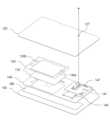
Figure 2 is an exploded perspective view of a smart card key for a vehicle according to an embodiment of the present invention.
Figure 3 is a diagram for explaining the configuration of a cover-integrated rigid body sheet according to an embodiment of the present invention.
Figure 4 is a side cross-sectional view for explaining the structure of a cover-integrated rigid body sheet according to an embodiment of the present invention.
Figure 5 is a flowchart of a method of manufacturing a smart card key for a vehicle according to an embodiment of the present invention.
이하의 내용은 단지 본 발명의 원리를 예시한다. 그러므로 당업자는 비록 본 명세서에 명확히 설명되거나 도시되지 않았지만 본 발명의 원리를 구현하고 본 발명의 개념과 범위에 포함된 다양한 장치를 발명할 수 있는 것이다. 또한, 본 명세서에 열거된 모든 조건부 용어 및 실시예들은 원칙적으로, 본 발명의 개념이 이해되도록 하기 위한 목적으로만 명백히 의도되고, 이와 같이 특별히 열거된 실시예들 및 상태들에 제한적이지 않는 것으로 이해되어야 한다.The following merely illustrates the principles of the invention. Therefore, those skilled in the art will be able to invent various devices that embody the principles of the present invention and are included in the spirit and scope of the present invention, although not explicitly described or shown herein. In addition, it is understood that all conditional terms and embodiments listed herein are, in principle, expressly intended solely for the purpose of ensuring that the concept of the invention is understood, and are not limited to the embodiments and conditions specifically listed as such. It has to be.
예를 들어, 명세서 전체에서, 어떤 부분이 다른 부분과 "연결"되어 있다고 할 때, 이는 "직접적으로 연결"되어 있는 경우뿐 아니라, 그 중간에 다른 부재를 사이에 두고 "간접적으로 연결"되어 있는 경우도 포함한다. 또한 어떤 부분이 어떤 구성요소를 "포함"한다고 할 때, 이는 특별히 반대되는 기재가 없는 한 다른 구성요소를 제외하는 것이 아니라 다른 구성요소를 더 구비할 수 있다는 것을 의미한다.For example, throughout the specification, when a part is said to be “connected” to another part, this means not only “directly connected” but also “indirectly connected” with another member in between. Also includes cases. Additionally, when a part is said to “include” a certain component, this does not mean that other components are excluded, but that other components can be added, unless specifically stated to the contrary.
또한, 본 발명의 원리, 관점 및 실시예들 뿐만 아니라 특정 실시예를 열거하는 모든 상세한 설명은 이러한 사항의 구조적 및 기능적 균등물을 포함하도록 의도되는 것으로 이해되어야 한다. 또한 이러한 균등물들은 현재 공지된 균등물뿐만 아니라 장래에 개발될 균등물 즉 구조와 무관하게 동일한 기능을 수행하도록 발명된 모든 소자를 포함하는 것으로 이해되어야 한다.Additionally, it is to be understood that any detailed description reciting principles, aspects, and embodiments of the invention, as well as specific embodiments, is intended to encompass structural and functional equivalents thereof. In addition, these equivalents should be understood to include not only currently known equivalents but also equivalents developed in the future, that is, all elements invented to perform the same function regardless of structure.
상술한 목적, 특징 및 장점은 첨부된 도면과 관련한 다음의 상세한 설명을 통하여 보다 분명해질 것이며, 그에 따라 본 발명이 속하는 기술분야에서 통상의 지식을 가진 자가 본 발명의 기술적 사상을 용이하게 실시할 수 있을 것이다. 또한, 본 발명을 설명함에 있어서 본 발명과 관련된 공지 기술에 대한 구체적인 설명이 본 발명의 요지를 불필요하게 흐릴 수 있다고 판단되는 경우에 그 상세한 설명을 생략하기로 한다.The above-described purpose, features and advantages will become clearer through the following detailed description in conjunction with the accompanying drawings, and accordingly, those skilled in the art will be able to easily implement the technical idea of the present invention. There will be. Additionally, in describing the present invention, if it is determined that a detailed description of known technologies related to the present invention may unnecessarily obscure the gist of the present invention, the detailed description will be omitted.
도 1은 본 발명의 실시 예에 따른 차량용 스마트 카드 키를 도시한 도면이며, 도 2는 본 발명의 실시 예에 따른 차량용 스마트 카드 키의 분해 사시도이다.Figure 1 is a diagram showing a smart card key for a vehicle according to an embodiment of the present invention, and Figure 2 is an exploded perspective view of a smart card key for a vehicle according to an embodiment of the present invention.
도 1 및 도 2를 참조하면, 본 발명의 실시 예에 따른 차량용 스마트 카드 키(100)는, 하나 이상의 시트 또는 레이어(층)을 포함하여, 프레스 공정 또는 접착제를 사용하여 고정되어 형성되며, 차량의 키 제어를 위한 회로 시트, 배터리, 센서 및 소정의 입출력장치가 내장된 것으로, 차량과의 무선 통신을 수행하며, 원격무선출입 기능, 차량 도어의 락킹 또는 언락킹 기능, 트렁크 도어의 언락킹 기능, 패닉 기능, 상태 정보 점등 기능 중 적어도 하나의 기능을 수행할 수 있다.Referring to Figures 1 and 2, the
그리고, 본 발명의 실시 예에 따른 차량용 스마트 카드 키(100)는, 차량용 스마트 카드 키(100)의 전체적인 강성을 유지하는 커버 일체형 강성 바디시트(120)를 형성하고, 상기 커버 일체형 강성 바디시트(120)의 하면의 일정 수용 영역에, 사전 설정된 깊이로 하나 이상의 모듈형 수용부를 형성하여, 전체 강성을 유지하는 내구성이 향상된 차량용 스마트 카드 키(100)를 사용자에게 제공할 수 있다.In addition, the vehicle
이를 구현하기 위한 본 발명의 실시 예에 따른 차량용 스마트 카드 키(100)는, 커버 일체형 강성 바디시트(120), 초박형 배터리(130), 회로 시트(140) 및 베이스 시트(150)를 포함한다.To implement this, the vehicle
또한, 상기 차량용 스마트 카드 키(100)는, 상부 페라이트 시트(170) 및 하부 페라이트 시트(180)를 더 포함할 수 있다. 본 도면에서는, 상술한 구성요소들만을 기재하였으나, 이에 한정되는 것은 아니며, 차량용 스마트 카드 키(100)의 상기 기능 구현을 위한 터치 입력부, 스위치 입력부, LED부 등의 다른 구성요소들이 더 추가될 수 있고, 부가 기능을 위해 디스플레이부, 생체 센서부 등이 추가로 포함될 수 있다.In addition, the vehicle
여기에서, 본 발명의 실시 예에 따른 차량용 스마트 카드 키(100)는 미리 정의된 기준에 따른 규격 사이즈와 두께에 맞게 제조될 수 있고, 각 시트의 사이즈와 두께는 차량용 스마트 카드 키(100)의 동작과 무선 통신 감도 등에 맞는 최적의 두께로 결정되어 결합되도록 구현될 수 있다.Here, the vehicle
먼저, 베이스 시트(150)는, 본 발명의 실시 예에 따른 차량용 스마트 카드 키(100)의 제1면을 지지하는 시트일 수 있다.First, the
그리고, 회로 시트(140)는 본 발명의 실시 예에 따른 차량용 스마트 카드 키(100)의 기능을 구현하기 위해 내장되는 코어 부재로서, 상기 베이스 시트(150)의 제2면 방향으로 적층되고, 상기 회로 시트(140)에 탑재되는 초박형 배터리(130)의 전력을 이용하여, 차량 ECU 시스템과의 무선 통신, 입출력 정보 제어 및 차량 제어 기능을 수행하는 하나 이상의 칩(chip) 모듈이 구비된 PCBA 회로를 포함할 수 있다.In addition, the
또한, 상기 회로 시트(140)는 상태 표시 위치에 상기 차량용 스마트 카드 키(100)의 상태 정보를 나타내는 발광소자(147)를 포함할 수 있으며, 상기 발광소자(147)는 전기를 빛으로 변환하는 소자로서, 발광 다이오드(LED), 반도체 레이저(LD), 고체 레이저(Solid Laser)를 사용할 수 있다.In addition, the
그리고, 상기 회로 시트(140)는, 무선 충전이 가능한 초박형 배터리(130), 차량과 무선 통신 시스템에 사용되는 3차원 코일 안테나(145), 상기 발광소자(147)를 포함하는 회로 소자 및 도선로(141)가 실장될 수 있고, 이를 전체적으로 커버하는 커버 일체형 강성 바디시트(120)가 적층될 수 있다.In addition, the
여기서, 상기 커버 일체형 강성 바디시트(120)는, 상기 회로 시트(140)에 실장되는 상기 초박형 배터리(130), 상기 3차원 코일 안테나(145) 및 상기 발광소자(147)를 포함하는 회로 소자 및 도선로(141)를 전체적으로 커버하도록 형성된 단일의 일체형 바디시트로 형성될 수 있다.Here, the cover-integrated
이러한, 커버 일체형 강성 바디시트(120)는 상기 회로 시트(140)상에 적층되고, 상기 차량용 스마트 카드 키(100)의 전체적인 강성이 유지되도록 형성될 수 있으며, 상기 회로 시트(140) 상에 탑재되는 상기 초박형 배터리(130), 상기 3차원 코일 안테나(145), 상기 발광소자(147)를 포함하는 각 회로 소자 및 도선로(141)에 대응하여 단차가 형성될 수 있다.This cover-integrated
보다 상세하게, 상기 커버 일체형 강성 바디시트(120)는, 상기 초박형 배터리(130), 상기 3차원 코일 안테나(145), 상기 발광소자(147)를 포함하는 각 회로 소자 및 도선로(141)에 대응하여, 상기 커버 일체형 강성 바디시트(120)의 하면의 일정 수용 영역이 사전 설정된 깊이로 형성되는 모듈형 수용부(121)를 포함할 수 있다.In more detail, the cover-integrated
특히, 상기 커버 일체형 강성 바디시트(120)는, 상기 회로 시트(140)의 상태 표시 영역에 배치된 발광소자(147)에 대응하여, 상기 발광소자(147)을 수용하면서 상기 발광소자(147)의 수직광이 투과되도록, 상기 커버 일체형 강성 바디시트(120)의 일정 수용 영역이 개구되어 형성되는 발광소자 투과부(127)를 더 포함할 수 있다.In particular, the cover-integrated
또한, 상기 발광소자 투과부(127)는 상기 발광소자(147)의 수직광을 투과시켜, 상부로 광을 발산시키는 역할을 수행한다.In addition, the light-emitting
그리고, 상기 발광소자 투과부(127)는, 상기 커버 일체형 강성 바디시트(120)에서, 상기 회로 시트(140)의 상기 상태 표시 영역에 배치된 상기 발광소자(147)의 수직광이 투과되는 투과 인쇄 영역일 수 있다.In addition, the light-emitting
여기서, 상기 투과 인쇄 영역은 스크린 인쇄 공법을 활용하여 형성할 수 있으며, 상기 스크린 인쇄 공법은 폴리에스테르와 같은 합성 섬유 또는 스테인리스나 각종 금속 섬유로 직조한 메시 형태의 스크린 마스크에 인쇄 패턴을 형성하고, 인쇄 잉크를 부어 스퀴지로 가압하여 밀어냄으로써 차량용 스마트 카드 키(100) 상에 상기 인쇄 패턴을 도포하는 공법일 수 있다.Here, the transmission printing area can be formed using a screen printing method, which forms a printing pattern on a mesh-shaped screen mask woven with synthetic fibers such as polyester or stainless steel or various metal fibers, This may be a method of applying the printing pattern on the vehicle
그리고, 상기 차량용 스마트 카드 키(100)는, 상부 페라이트 시트(170) 및 하부 페라이트 시트(180)를 더 포함할 수 있어, 상기 회로 시트(140)상의 무선 충전 회로 영역상에, 상부에서 무선 충전 회로 영역 방향으로 작용하는 전자기장를 차폐하기 위한 상부 페라이트 시트(170)가 상기 커버 일체형 강성 바디시트(120)와 상기 회로 시트(140) 사이에 적층 형성될 수 있다.In addition, the vehicle
그리고, 상기 하부 페라이트 시트(180)는, 상기 베이스 시트(150)의 상면에 적층되어, 상기 회로 시트(140)의 무선 충전 회로 영역을 제외한 일부 영역의 전자기장을 차폐할 수 있다.In addition, the
이러한, 상부 페라이트 시트(170) 및 하부 페라이트 시트(180)의 구성은 무선 충전 코일의 무선 충전이 이루어지는 동안의 발열을 최소화할 수 있으면서도, 무선 충전 기능 및 차량용 스마트 카드 키(100)의 전체적인 동작이 유지될 수 있도록 한다.This configuration of the
특히, 상부 페라이트 시트(170) 및 하부 페라이트 시트(180)는 연자성체 금속 분말 시트와 수지가 혼합 형성되는 형태로 구성될 수 있고, 상기 차량용 스마트 카드 키(100)를 구성하는 상기 회로 시트(140) 및 상기 초박형 배터리(130)는, 상기 페라이트 시트(170, 180)를 사전 접착 처리할 수도 있다.In particular, the
그리고, 페라이트(Ferrite)는 철을 가루로 만든 후 겉표면을 산화시켜 절연이 되게 하고, 압력을 가해 모양을 만들어 사용할 수 있다. 또한, 페라이트는 강자성의 절연체로, 분말 형태로 구현할 경우 부착력이 높아질 뿐만 아니라 적층에 의해 추가적인 절연층을 구성하게 되어 초박형 배터리(130) 및 회로 시트(140)의 무선 충전 회로와 다른 시트 간의 절연 기능이 더 향상될 수 있다.Additionally, ferrite can be used by grinding iron into powder, oxidizing the outer surface to insulate it, and shaping it by applying pressure. In addition, ferrite is a ferromagnetic insulator, which not only increases adhesion when implemented in powder form, but also forms an additional insulating layer by lamination, thereby providing insulation between the
상기 차량용 스마트 카드 키(100)를 제조함에 있어서, 상기 회로 시트(140)와 상기 초박형 배터리(130)를 적층하여 고정할 수 있고, 상기 회로 시트(140)와 상기 초박형 배터리(130) 사이에 상기 상부 페라이트 시트(170)를 적층하여 고정할 수 있으며, 회로 시트(140)의 하부에는 하부 페라이트 시트(170)를 적층 고정할 수 있다. 이러한 적층 고정에는, 양면 테이프, 접착제 등이 이용될 수 있다. 이에 따라 적층 고정된 조립체를 코어 모듈이라고 할 수 있다.In manufacturing the vehicle
그리고, 상기 차량용 스마트 카드 키(100)는, 상기 적층 고정된 코어 모듈을 중심으로, 상기 베이스 시트(150) 및 커버 일체형 강성 바디시트(120)를 접착제를 이용하여 상하로 부착하고, 저온 프레스 라미네이팅을 처리함에 따라 완성품으로 제조될 수 있다.In addition, the vehicle
여기서, 상기 저온 프레스 라미네이팅은, 약 50도에서 저온 라미네이팅 처리되는 것이 바람직할 수 있다.Here, the low-temperature press laminating may preferably be performed at a temperature of about 50 degrees.
이러한, 상기 라미네이팅 처리는, 일상적으로 코팅이라고 불리며, 대상이 되는 물체에 1겹 이상의 얇은 레이어를 덧씌워 표면을 보호하고 강도 및 안정성을 높이는 기술이다.The laminating process, commonly called coating, is a technology that protects the surface and increases strength and stability by covering the target object with one or more thin layers.
또한, 상기 라미네이팅 처리는 라미네이터로 불리우는 장비로 고열의 온도와 압력을 가하여 코팅 재질을 대상 물체에 접착시키는 기술이다.In addition, the laminating process is a technology that adheres the coating material to the target object by applying high temperature and pressure using equipment called a laminator.
이에 따라, 상기 라미네이팅 처리 기술이, 상기 초박형 배터리(130)와 상기 회로 시트(140)에 적용되려면, 상기 초박형 배터리(130)가 고열의 온도 및 압력에 의해 터지는 것을 방지하기 위해, 상기 초박형 배터리(130)는 약 50도의 온도에서 저온 라미네이팅 처리되는 것이 바람직할 수 있다.Accordingly, in order to apply the laminating technology to the
그리고, 상기 차량용 스마트 카드 키(100)는 평탄성을 유지하기 위해, 상기 하부 페라이트 시트(180)의 하면에 베이스 시트(150)가 형성될 수 있다.In order to maintain the flatness of the vehicle
여기에서, 상기 베이스 시트(150) 및 상기 커버 일체형 강성 바디시트(120)는, 상기 회로 시트(140) 상에 형성되는 상기 각 회로 소자 및 도선로(141)의 변형을 보호하기 위해, 일정 강성을 갖는 에폭시 소재로 조성될 수 있으며, 상기 에폭시 수지는 기계적, 화학적 물성이 우수하고, 가공성도 좋아 다양한 용도로 쓰일 수 있다.Here, the
이에 따라, 상기 베이스 시트(150) 및 상기 커버 일체형 강성 바디시트(120)는 외부의 열이나 외력에 의한 상기 회로 소자 및 도선로(141)의 변형을 보호할 뿐만 아니라, 상기 발광소자(147)의 변형을 보호하여, 전체적인 상기 차량용 스마트 카드 키(100)의 평탄함을 유지함에 따라, 상기 차량용 스마트 카드 키(100)의 외관도 유지시킬 수 있다.Accordingly, the
또한, 상기 베이스 시트(150)는, 상기 회로 소자 및 도선로(141)의 변형을 보호하고, 상기 차량용 스마트 카드 키(100)의 평탄함을 유지할 수 있어, 별도의 프린팅 시트가 추가될 수 있다.In addition, the
그리고, 상기 커버 일체형 강성 바디시트(120)는, 상기 차량용 스마트 카드 키(100)의 평탄함을 유지하도록, 일정 강성을 갖는 에폭시 소재로 조성됨에 따라, 별도의 구성 시트없이 프린팅 시트만 추가 구비되는 장점이 있다.In addition, the cover-integrated
상술한 바와 같이, 본 발명의 실시 예에 따른 차량용 스마트 카드 키(100)는, 별도의 고압 프레스 공정 처리 없이 상기 회로 시트(140) 및 상기 초박형 배터리(130)의 저온 라미네이팅 처리만을 수행하고, 상술한 구성요소들을 접착제에 의한 시트 정합 과정을 통해, 하나의 카드 몸체를 형성하도록 가공될 수 있다.As described above, the
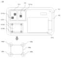
도 3은 본 발명의 실시 예에 따른 커버 일체형 강성 바디시트의 구성을 설명하기 위한 도면이다.Figure 3 is a diagram for explaining the configuration of a cover-integrated rigid body sheet according to an embodiment of the present invention.
도 3을 참조하면, 본 발명의 실시 예에 따른 커버 일체형 강성 바디시트(120)는, 상기 차량용 스마트 카드 키(100)의 강성을 유지하도록 형성될 수 있고, 모듈형 수용부(121)를 포함할 수 있다.Referring to FIG. 3, the cover-integrated
여기에서, 상기 모듈형 수용부(121)는, 상기 회로 시트(140) 상에 형성되는 상기 3차원 코일 안테나(145), 상기 초박형 배터리(130) 및 상기 발광소자(147)에 대한 회로 소자 및 도선로(141)의 돌출 형상에 대응하여, 상기 커버 일체형 강성 바디시트(120)의 하면의 일정 수용 영역이 사전 설정된 깊이로 하나 이상 형성될 수 있다.Here, the modular
그리고, 상기 모듈형 수용부(121)는, 모듈 수용부(1211), 배터리 수용부(1213) 및 3차원 코일 안테나 수용부(1215)를 포함할 수 있다.And, the modular
그리고, 상기 모듈 수용부(1211)는, 제1 모듈 수용부(1211a) 및 제2 모듈 수용부(1211b)를 포함할 수 있다.And, the
여기에서, 상기 제1 모듈 수용부(1211a)는, 제1 회로 소자 및 도선로의 제1 돌출 형상에 따라 형성되는, 제1 회로 영역에 대응하여, 제1 함몰 깊이로 형성될 수 있으며, 상기 제2 모듈 수용부(1211b)는, 상기 제1 회로 영역에 포함되는 제2 회로 영역의 회로 소자 및 도선로의 제2 돌출 형상에 대응하여, 제2 함몰 깊이로 형성될 수 있다.Here, the first
그리고, 상기 제1 모듈 수용부(1211a) 및 상기 제2 모듈 수용부(1211b)는 서로 상이한 깊이로 형성되어 단차가 형성될 수 있다.Additionally, the first
보다 상세하게, 상기 회로 소자 및 도선로(141)는, 상기 차량용 스마트 카드 키(100)와 차량의 무선 통신에 있어서, 상기 구성 모듈을 전기적으로 연결하고 기계적으로 지원하도록, 상기 회로 시트(140) 상에 다양한 형상 및 두께를 가지는 모듈로 형성될 수 있다.In more detail, the circuit elements and
이에 따라, 상기 모듈 수용부(1211)에 포함되는 제1 모듈 수용부(1211a) 및 제2 모듈 수용부(1211b)는, 상기 회로 시트(140) 상에 실장되는 상기 회로 소자 및 도선로(141)의 돌출 형상에 따라, 서로 상이한 깊이로 형성되어 단차가 형성될 수 있다.Accordingly, the first
그리고, 상기 배터리 수용부(1213)는, 상기 초박형 배터리(130)에 대응하는 위치에 형성되고, 상기 초박형 배터리(130)의 돌출 형상 또는 상기 초박형 배터리(130)의 열팽창에 의한 외관변형에 대응하는 제3 함몰 깊이로 형성될 수 있다.In addition, the
상기 초박형 배터리(130)는, 무선 충전이 가능하며, 고온(약 60도 이상)의 환경에서 전해액의 미세한 열팽창에 의한 외관변형이 발생될 수 있는 통상의 배터리로 구성될 수 있다. 예를 들어, 리튬전지의 경우, 리튬이온이 양극과 음극 사이를 잘 이동할 수 있도록 하는, 전해액을 포함하는 배터리일 수 있다.The
이에 따라, 상술한 바와 같이, 상기 배터리 수용부(1213)는, 상기 초박형 배터리(130)에 대응하는 위치에 형성되고, 상기 초박형 배터리(130)의 돌출 형상뿐만 아니라, 상기 초박형 배터리(130)의 열팽창에 의한 외관변형에 대응하는 제3 함몰 깊이로 형성될 수 있다.Accordingly, as described above, the
그리고, 상기 3차원 코일 안테나 수용부(1215)는, 상기 3차원 코일 안테나(145)의 돌출 형상에 대응하여, 상기 커버 일체형 강성 바디시트(120)의 일정 수용 영역에 형성될 수 있다.In addition, the three-dimensional coil
여기서, 상기 3차원 코일 안테나(145)는, 차량 시스템과 양방향 통신을 하며, 차량과 무선 통신을 수행하는 시스템에 사용되어 차량과 스마트 카드 키의 인증과 각종 데이터처리를 수행한다.Here, the three-
또한, 예를 들어, 3차원 코일 안테나(145)를 이용한 차량용 스마트 카드 키(100)는 차량으로부터 떨어진 일정 거리에서 LF(Low Frequency)로 데이터를 수신하여, 상기 차량용 스마트 카드 키(100)의 유무에 따라 상기 차량의 도어의 개폐를 결정하고, 상기 수신한 데이터가 정상일 경우 RF(Radio Frequency)로 데이터를 상기 차량으로 송신하여, 차량이 LOCK, UNLOCK, TRUNK, PANIC과 같은 작동을 수행할 수 있다.In addition, for example, the vehicle
그리고, 상술한 바와 같이, 차량과 무선 통신을 수행하는 시스템에 이용되는 상기 3차원 코일 안테나(145)는 3차원 코일 안테나 바디부(145a) 및 차량용 스마트 카드 키(100)의 전체 두께를 줄일 수 있도록, 일정 두께 만큼 벤딩 처리된 각각의 벤딩 리드부(145b, 145c, 145d, 145e)를 포함할 수 있다.And, as described above, the three-
여기서, 상기 3차원 코일 안테나(145)의 바디부(145a)는, 입체 형상의 일정 두께를 가지도록 형성될 수 있으며, 상기 3차원 코일 안테나 바디부(145a)의 돌출 형상에 대응하여, 상기 3차원 코일 안테나 수용부(1215)에 제4 함몰 깊이의 바디 수용부(1215a)가 형성될 수 있다.Here, the
또한, 상기 3차원 코일 안테나(145)의 각 모서리에는, 상기 벤딩 리드부(145b, 145c, 145d, 145e)가 형성되고, 상기 벤딩 리드부(145b, 145c, 145d, 145e)에 대응하여, 벤딩 구조를 수용하도록 상기 3차원 코일 안테나 수용부(1215)에 제5 함몰 깊이로 벤딩 리드 수용부(1215b)가 돌출 형성될 수 있다.In addition, bending
이에 따라, 상기 바디 수용부(1215a)는, 상기 3차원 코일 안테나(145)가 차량과 원활한 무선 통신을 수행하도록, 상기 3차원 코일 안테나의 바디부(145a)에 대응하여, 제4 함몰 깊이로 형성될 수 있다.Accordingly, the
그리고, 상기 벤딩 리드 수용부(1215b)는, 상기 3차원 코일 안테나(145)의 각 모서리에 형성되는 상기 벤딩 리드부(145b, 145c, 145d, 145e)에 대응하여, 상기 회로 시트(140)에 고정될 수 있도록 제5 함몰 깊이로 형성될 수 있다.In addition, the bending
여기서, 상기 바디 수용부(1215a) 및 상기 벤딩 리드 수용부(1215b)는, 서로 상이한 깊이로 형성되어 단차가 형성될 수 있으며, 상기 제4 함몰 깊이는 상기 제5 함몰 깊이보다 상대적으로 깊을 수도 있다.Here, the
이러한, 상기 모듈형 수용부(121)는, 상기 회로 시트(140)에 실장된 각 회로 소자 및 도선로(141)의 돌출 형상에 대응하여, 상기 커버 일체형 강성 바디시트(120)의 하면의 일정 수용 영역이, 사전 설정된 깊이로 하나 이상 형성될 수 있다.The modular
또한, 상기 모듈형 수용부(121)는, 상기 회로 소자 및 도선로(141)를 전체적으로 수용하는 면적으로 형성될 수 있으며, 상기 회로 소자 및 도선로(141)의 돌출 형상에 따라 사전 설정된 깊이로 형성되고 단차가 형성될 수 있다.In addition, the modular
보다 상세하게, 상기 회로 소자 및 도선로(141)는, 상기 차량용 스마트 카드 키(100)와 차량의 무선 통신에 있어서, 상기 회로 시트(140)에 실장된 각 회로 소자를 전기적으로 연결하고 기계적으로 지원하도록, 상기 회로 시트(140) 상에 다양한 형상 및 두께를 가지는 모듈로 형성될 수 있다.In more detail, the circuit elements and
그리고, 상기 모듈형 수용부(121)는, 상기 발광소자(147)의 수직광이 투과되도록, 상기 발광소자(147)에 대응하는 위치에, 상기 커버 일체형 강성 바디시트(120)의 일정 수용 영역이 개구되어 형성되는 발광소자 투과부(127)를 더 포함할 수 있는 바, 상기 모듈형 수용부(121)를 구성하는 각 수용부의 가공 깊이에 대하여는 보다 구체적으로 후술하도록 한다.In addition, the modular receiving
도 4는 본 발명의 실시 예에 따른 커버 일체형 강성 바디시트의 구조를 설명하기 위한 측단면도이다.Figure 4 is a side cross-sectional view for explaining the structure of a cover-integrated rigid body sheet according to an embodiment of the present invention.
도 4(a)는 본 발명의 실시 예에 따른 커버 일체형 강성 바디시트의 배터리 수용부의 구조를 도시한 측단면도이다.Figure 4(a) is a side cross-sectional view showing the structure of the battery accommodation portion of the cover-integrated rigid body sheet according to an embodiment of the present invention.
여기서, 커버 일체형 강성 바디시트(120)는, 회로 시트(140)에 실장된 각 회로 소자 및 도선로(141)의 돌출 형상에 대응하여, 상기 커버 일체형 강성 바디시트(120)의 하면의 일정 수용 영역이 사전 설정된 깊이를 가지도록 하나 이상의 모듈형 수용부(121)가 가공 형성될 수 있다.Here, the cover-integrated
이에 따라, 본 발명의 실시 예에 따른 차량용 스마트 카드 키(100)가, 사용자에게 얇은 카드 제품으로 제공되기 위해, 상기 모듈형 수용부(121)를 구성하는 각 수용부는 서로 상이한 깊이로 가공될 수 있으며, 이에 따라 단차가 형성될 수 있다.Accordingly, in order for the vehicle
예를 들어, 상기 차량용 스마트 카드 키(100)는, 상기 모듈형 수용부(121)의 가공 깊이가 깊을수록, 상기 가공 깊이를 제외한 상기 커버 일체형 강성 바디시트(120)의 두께가 얇아져 상기 차량용 스마트 카드 키(100)를 제작할 시 외관불량이 발생할 수 있다.For example, in the
또한, 상기 차량용 스마트 카드 키(100)는, 상기 모듈형 수용부(121)의 가공 깊이가 얕을수록, 상기 가공 깊이를 제외한 커버 일체형 강성 바디시트(120)의 두께가 두꺼워져 회로 시트(140)과의 전기적 간섭 및 출동이 발생할 수 있다.In addition, in the vehicle
이에 따라, 상기 차량용 스마트 카드 키(100)는, 전체 강성이 유지되도록, 상기 모듈형 수용부(121)의 가공 깊이를 사전 설정된 수치로, 상기 회로 시트(140)에 실장된 각 회로 소자 및 도선로(141)의 돌출 형상에 대응하여, 가공하는 것이 바람직할 수 있다.Accordingly, the vehicle
또한, 상기 차량용 스마트 카드 키(100)는 굽힘력 기준을 충족하여 전체적인 강성을 유지하기 위해, 상기 커버 일체형 강성 바디시트(120)의 외곽에 일정 폭을 가지는 인레이 바디살(122)을 포함할 수 있다.In addition, the vehicle
여기서, 상기 모듈형 수용부(121)는, 모듈 수용부(1211), 배터리 수용부(1213) 및 3차원 코일 안테나 수용부(1215)를 포함할 수 있다.Here, the modular
도 4(a)는 본 발명의 실시 예에 따른 커버 일체형 강성 바디시트의 3차원 코일 안테나 수용부 및 모듈 수용부의 구조를 도시한 측단면도이다.Figure 4(a) is a side cross-sectional view showing the structures of the three-dimensional coil antenna accommodating part and the module accommodating part of the cover-integrated rigid body sheet according to an embodiment of the present invention.
도 4(a)를 참조하면, 본 발명의 실시 예에 따른 모듈 수용부(1211)는, 상기 회로 시트(140)에 실장된 회로 소자 및 도선로(141)를 수용하며, 상기 회로 소자 및 도선로(141)의 돌출 형상에 따라 서로 상이한 깊이로 형성될 수 있다.Referring to FIG. 4(a), the
보다 구체적으로, 상기 모듈 수용부(1211)는, 제1 모듈 수용부(1211a) 및 제2 모듈 수용부(1211b)를 포함할 수 있으며, 상기 제1 모듈 수용부(1211a)는, 제1 회로 소자 및 도선로의 제1 돌출 형상에 따라 형성되는, 제1 회로 영역에 대응하여, 제1 함몰 깊이로 형성될 수 있다.More specifically, the
예를 들어, 상기 제1 모듈 수용부(1211a)는, 상기 회로 시트(140) 상에 실장된 제1 회로 소자 및 도선로를 전체적으로 커버하도록, D1의 두께를 가지는 제1 회로 소자 및 도선로를 수용할 수 있다.For example, the first
이에 따라, 두께 D1을 가지는 상기 제1 회로 소자 및 도선로와, 두께 h를 가지는 상기 회로 시트(140)에 의해, 상기 제1 모듈 수용부(1211a)는 D1 + h 만큼의 제1 함몰 깊이로 가공 형성될 수 있으며, 상기 제1 모듈 수용부(1211a)는 D1 만큼의 단차가 형성될 수 있다.Accordingly, by the first circuit element and conductor line having a thickness D1 and the
예를 들어, 상기 제1 모듈 수용부(1211a)는, 상기 회로 시트(140) 상에 형성된 제1 회로 소자 및 도선로를 전체적으로 수용하는 깊이로 형성되며, 1.2mm ?? 0.1mm 내지 1.2mm + 0.1mm 만큼의 가공 깊이로 형성되는 것이 바람직할 수 있다.For example, the first
또한, 상기 제2 모듈 수용부(1211b)는, 상기 제1 회로 영역에 포함되는 제2 회로 영역의 회로 소자 및 도선로의 제2 돌출 형상에 대응하여, 제2 함몰 깊이로 형성될 수 있다.Additionally, the second
그리고, 두께 D2를 가지는 상기 제2 회로 영역의 회로 소자 및 도선로와, 두께 h를 가지는 상기 회로 시트(140)에 의해, 상기 제2 모듈 수용부(1211b)는 D2 + h 만큼의 제2 함몰 깊이로 가공 형성될 수 있으며, 상기 제2 모듈 수용부(1211b)는 D2 만큼의 단차가 형성될 수 있다.And, due to the circuit elements and conductive lines of the second circuit area having a thickness D2 and the
보다 구체적으로, 상기 제2 모듈 수용부(1211b)는, 상기 회로 시트(140) 상에 형성된 상기 제1 회로 영역에 포함되는 제2 회로 영역의 회로 소자 및 도선로를 수용하는 깊이로 형성되며, 1.4mm ?? 0.1mm 내지 1.4mm + 0.1mm 만큼의 가공 깊이로 형성되는 것이 바람직할 수 있다.More specifically, the second
그리고, 본 발명의 실시 예에 따른 3차원 코일 안테나 수용부(1215)는, 3차원 코일 안테나 바디부(145a) 및 일정 두께 만큼 벤딩 처리된 각각의 벤딩 리드부(145b, 145c, 145d, 145e)를 수용할 수 있다.In addition, the three-dimensional coil
이에 따라, 상기 3차원 코일 안테나(145)의 3차원 코일 안테나 바디부(145a)는, 입체 형상의 일정 두께를 가지도록 형성될 수 있으며, 상기 3차원 코일 안테나 수용부(1215)에는, 상기 3차원 코일 안테나의 바디부(145a)의 돌출 형상에 대응하도록, 상기 커버 일체형 강성 바디시트(120)의 일정 수용 영역에 제4 함몰 깊이의 바디 수용부(1215a)가 형성될 수 있다.Accordingly, the three-dimensional coil
또한, 상기 3차원 코일 안테나 수용부(1215)는, 상기 3차원 코일 안테나(145)의 각 모서리에 상기 벤딩 리드부(145b, 145c, 145d, 145e)가 형성되고, 상기 벤딩 리드부(145b, 145c, 145d, 145e)에 대응하여, 벤딩 구조를 수용하도록 제5 함몰 깊이로 벤딩 리드 수용부(1215b)가 형성될 수 있다.In addition, the three-dimensional coil
이에 따라, 상기 벤딩 리드 수용부(1215b)는 회로 시트(140)의 삽입된 상기 3차원 코일 안테나(145)가 수용될 수 있으며, 커버 일체형 강성 바디시트(120)에 상기 회로 시트(140)의 두께 및 상기 3차원 코일 안테나(145)의 벤딩 리드부(145b, 145c, 145d, 145e)의 두께 만큼의 깊이로 상기 벤딩 리드 수용부(1215b)가 가공 형성될 수 있다.Accordingly, the bending
예를 들어, 두께 D3를 가지는 상기 벤딩 리드부(145b, 145c, 145d, 145e) 및 두께 h를 가지는 회로 시트(140)에 의해, 상기 벤딩 리드 수용부(1213b)는 D3 + h 만큼의 제4 함몰 깊이로 가공 형성될 수 있으며, 상기 벤딩 리드부(145b, 145c, 145d, 145e)의 두께 D3 만큼의 단차가 형성될 수 있다.For example, by the bending
보다 구체적으로, 3차원 코일 안테나의 바디부(145a) 및 일정 두께 만큼 벤딩 처리된 각각의 벤딩 리드부(145b, 145c, 145d, 145e)에 대응하여, 돌출 개구되도록, 1.2mm - 0.1mm 내지 1.2mm + 0.1mm의 가공 깊이로 개구되어 형성되는 것이 바람직할 수 있다.More specifically, corresponding to the
도 4(b)에 도시된 바와 같이, 상기 배터리 수용부(1213)는, 상기 초박형 배터리(130)에 대응하는 위치에 형성되고, 상기 초박형 배터리(130)의 돌출 형상 및 상기 초박형 배터리(130)의 열팽창에 의한 외관변형에 대응하는 제3 함몰 깊이로 개구되어 형성될 수 있다.As shown in FIG. 4(b), the
여기서, 상기 배터리 수용부(1213)는 초박형 배터리 몸체부(130a) 및 초박형 배터리 연결부(130b)를 포함하는 초박형 배터리(130)를 수용한다.Here, the
이를 위해, 상기 배터리 수용부(1213)는 초박형 배터리 몸체부(130a) 및 초박형 배터리 연결부(130b)의 돌출 형상에 대응하는 깊이로 형성될 수 있다.To this end, the
보다 구체적으로, 상기 배터리 수용부(1213)에서 상기 초박형 배터리 연결부(130b)를 수용하는 부분은, 전극 구조물로서 온도에 따른 팽창이 거의 이루어지지 않으므로, 상기 커버 일체형 강성 바디시트(120)의 배터리 수용부(1213)에서 타단에 위치하고, 상기 초박형 배터리 연결부(130b)의 전극 두께를 고려하여 맞춤형 구조로 형성될 수 있다.More specifically, the portion of the
그리고, 상기 배터리 수용부(1213)에서 상기 초박형 배터리 몸체부(130a)를 수용하는 부분은, 상기 초박형 배터리 몸체부(130a)의 돌출 형상 및 상기 초박형 배터리(130)의 열팽창에 의한 외관변형에 대응하여, 제3 함몰 깊이로 형성될 수 있다.In addition, the portion of the
예를 들어, 상기 초박형 배터리 몸체부(130a) 두께를 D4, 상기 초박형 배터리 연결부(130b) 두께를 D5, 상기 초박형 배터리(130)의 상부가 전체적으로 수용되어, 상기 초박형 배터리 몸체부(130a)가 열팽창에 따라 부풀었을 때의 두께 및 외관변형을 고려하여, 상기 배터리 수용부(1213)와 상기 초박형 배터리 몸체부(130a) 사이의 유격거리를 m이라고 할 수 있다.For example, the thickness of the
그리고, 상술한 바와 같이, 상기 초박형 배터리 연결부(130b)는, 전극 구조물로서 온도에 따른 팽창이 거의 이루어지지 않으므로, 두께 D5를 고려한 맞춤형 구조로 상기 배터리 수용부(1213)에서 상기 초박형 배터리 연결부(130b)를 수용하는 부분이 형성될 수 있다.And, as described above, since the ultra-thin
또한, 상기 배터리 수용부(1213)는 상기 초박형 배터리 몸체부(130a)의 두께 D4와, 상기 회로 시트(140)의 두께 h 와, 상기 초박형 배터리 몸체부(130a)가 열팽창에 의해 부풀었을 때의 두께 및 외관변형을 고려하여, 상기 초박형 배터리 몸체부(130a)의 상부를 전체적으로 커버하도록 상기 배터리 수용부(1213)는 D4 + m + h 만큼의 제3 함몰 깊이로 개구되어 형성될 수 있다.In addition, the
이에 따라, 상기 배터리 수용부(1213)는, 상기 초박형 배터리 몸체부(130a) 및 상기 초박형 배터리 연결부(130b), 상기 배터리 수용부(1213)와 상기 초박형 배터리 몸체부(130a) 사이의 유격거리에 의해, D4 + m ?? D5 만큼의 단차가 형성될 수 있다.Accordingly, the
예를 들어, 열팽창에 의한 상기 초박형 배터리(130)의 두께 변화를 고려하여 상기 배터리 수용부(1213)와 상기 초박형 배터리 몸체부(130a) 사이의 유격거리 m은 대략 0.1mm 내지 0.2mm 사이의 범위인 것이 바람직하다.For example, considering the change in thickness of the
이에 따라, 1.6T(1.6mm) 두께의 커버 일체형 강성 바디시트(120)를 사용할 경우, 상기 배터리 수용부(1213)는, 1.25mm ?? 0.2mm 내지 1.25mm + 0.2mm 만큼의 가공 깊이로 형성되는 것이 바람직할 수 있다.Accordingly, when using the cover-integrated
그리고, 상기 초박형 배터리 몸체부(130a)의 두께가 0.45mm이고, 상기 초박형 배터리 연결부(130b)의 두께가 0.05mm인 초박형 배터리(130)를 사용할 경우, 상기 배터리 수용부(1213)는 1.25mm ?? 0.2mm ?? 0.05mm 내지 1.25mm + 0.2mm - 0.05mm 만큼의 단차가 형성될 수 있다.In addition, when using an
그리고, 도 4(a) 및 도 4(b)에 도시된 바와 같이, 상기 차량용 스마트 카드 키(100)는 굽힘력 기준을 충족하여 전체적인 강성을 유지하기 위해, 상기 커버 일체형 강성 바디시트(120)의 외곽에 일정 폭을 가지는 인레이 바디살(122)을 포함할 수 있다.And, as shown in FIGS. 4(a) and 4(b), the vehicle
여기서, 상기 굽힘력 기준은, 250N 일 수 있고, 이에 따라, 본 발명의 실시 예에 따른 상기 커버 일체형 강성 바디시트(120)의 외곽에 일정 폭을 가지는 인레이 바디살(122)이 형성되는 것이 바람직할 수 있다.Here, the bending force standard may be 250N, and accordingly, it is preferable that an
도 5는 본 발명의 실시 예에 따른 차량용 스마트 카드 키의 제조 방법에 대한 흐름도이다.Figure 5 is a flowchart of a method of manufacturing a smart card key for a vehicle according to an embodiment of the present invention.
도 5를 참조하면, 회로 시트와 상기 회로 시트에 실장된 초박형 배터리를 저온 라미네이팅 처리한다(S101).Referring to Figure 5, the circuit sheet and the ultra-thin battery mounted on the circuit sheet are subjected to low-temperature laminating (S101).
여기서, 초박형 배터리(130)가 열에 의해 팽창하는 것을 방지하기 위해, 회로 시트(140) 상에 상기 초박형 배터리(130)를 탑재하여, 저온에서 라미네이팅 공정 처리한다.Here, in order to prevent the
보다 상세하게, 상기 라미네이팅 공정 처리는 라미네이터로 불리우는 장비로 고열의 온도와 압력을 가하여 코팅 재질을 대상 물체에 접착시키는 기술이다.More specifically, the laminating process is a technology that adheres the coating material to the target object by applying high temperature and pressure with equipment called a laminator.
이에 따라, 상기 초박형 배터리(130)와 상기 회로 시트(140)에 상기 라미네이팅 처리 기술을 적용하려면, 상기 초박형 배터리(130)가 고열의 온도 및 압력에 의해 터지는 것을 방지하기 위해, 상기 초박형 배터리(130)는 약 50도의 온도에서 저온 라미네이팅 처리되는 것이 바람직할 수 있다.Accordingly, in order to apply the laminating processing technology to the
다음으로, 상기 회로 시트에 실장된 각 회로 소자 및 도선로의 돌출 형상에 대응하는 커버 일체형 강성 바디시트의 일정 수용 영역에, 상기 회로 시트에 실장된 각 회로 소자 및 도선로의 돌출 형상에 대응하여 사전 설정된 깊이로 모듈형 수용부를 가공한다(S103).Next, in a certain receiving area of the cover-integrated rigid body sheet corresponding to the protruding shape of each circuit element and conductive line mounted on the circuit sheet, corresponding to the protruding shape of each circuit element and conductive line mounted on the circuit sheet, Process the modular receiving portion to a preset depth (S103).
여기서, 상술한 바와 같이 형성된 상기 커버 일체형 강성 바디시트(120)는, 본 발명의 실시 예에 따른 회로 시트(140)에 실장된 각 회로 소자 및 도선로(141)의 돌출 형상에 대응하여, 사전 설정된 깊이로 하나 이상의 모듈형 수용부(121)가 형성될 수 있다.Here, the cover-integrated
이러한, 상기 모듈형 수용부(121)는, 모듈 수용부(1211), 배터리 수용부(1213) 및 3차원 코일 안테나 수용부(1215)를 포함할 수 있다.The modular
그리고, 상기 모듈 수용부(1211)는, 제1 모듈 수용부(1211a) 및 제2 모듈 수용부(1211b)를 포함할 수 있다.Additionally, the
여기에서, 상기 제1 모듈 수용부(1211a)는, 제1 회로 소자 및 도선로의 제1 돌출 형상에 따라 형성되는, 제1 회로 영역에 대응하여, 제1 함몰 깊이로 형성될 수 있으며, 상기 제2 모듈 수용부(1211b)는, 상기 제1 회로 영역에 포함되는 제2 회로 영역의 회로 소자 및 도선로의 제2 돌출 형상에 대응하여, 제2 함몰 깊이로 형성될 수 있다.Here, the first
그리고, 상기 제1 모듈 수용부(1211a) 및 상기 제2 모듈 수용부(1211b)는 서로 상이한 깊이로 형성되어 단차가 형성될 수 있다.Additionally, the first
또한, 상기 배터리 수용부(1213)는, 상기 초박형 배터리(130)에 대응하는 위치에 형성되고, 상기 초박형 배터리(130)의 돌출 형상 또는 상기 초박형 배터리(130)의 열팽창에 의한 외관변형에 대응하는 제3 함몰 깊이로 형성될 수 있다.In addition, the
그리고, 상기 3차원 코일 안테나 수용부(1215)는, 바디 수용부(1215a) 및 벤딩 리드 수용부(1215b)를 포함할 수 있다.Additionally, the three-dimensional coil
여기서, 상기 바디 수용부(1215a)는, 상기 3차원 코일 안테나(145)의 바디부(145a)의 돌출 형상에 대응하여, 상기 3차원 코일 안테나 수용부(1215)에 제4 함몰 깊이로 형성될 수 있다.Here, the
또한, 상기 벤딩 리드 수용부(1215b)는, 상기 3차원 코일 안테나(145)의 각 모서리에 형성되는 벤딩 리드부(145b, 145c, 145d, 145e)에 대응하여, 벤딩 구조를 수용하도록 상기 3차원 코일 안테나 수용부(1215)에 제5 함몰 깊이로 돌출 형성될 수 있다.In addition, the bending
여기서, 상기 제4 함몰 깊이는 상기 제5 함몰 깊이보다 상대적으로 깊게 가공될 수도 있다.Here, the fourth depression depth may be processed to be relatively deeper than the fifth depression depth.
마지막으로, 상기 차량용 스마트 카드 키의 제1면을 지지하는 베이스 시트 상에, 상기 저온 라미네이팅 공정 처리된 상기 회로 시트 및 상기 초박형 배터리, 상기 커버 일체형 강성 바디시트를 적층하여 접착 고정한다(S105).Finally, on the base sheet supporting the first side of the smart card key for the vehicle, the circuit sheet treated with the low-temperature laminating process, the ultra-thin battery, and the cover-integrated rigid body sheet are stacked and adhesively fixed (S105).
그리고, 차량용 스마트 카드 키(100)는, 상기 차량용 스마트 카드 키(100)의 제1면을 지지하는 베이스 시트(150) 상에, 상기 저온 라미네이팅 처리된 회로 시트(140) 및 상기 초박형 배터리(130), 상기 커버 일체형 강성 바디시트(120)를 적층하여, 상기 구성 시트를 정합 및 고온 프레스 처리 없이 접착제만을 사용하여 견고하게 부착할 수 있으며, 하나의 차량용 스마트 카드 키(100)의 몸체를 구성하도록 가공할 수 있다.In addition, the vehicle
여기서, 상기 상부 페라이트 시트(170)는 상기 회로 시트(140)상의 무선 충전 회로 영역상에, 상부에서 무선 충전 회로 영역 방향으로 작용하는 전자기장를 차폐하기 위한 시트일 수 있다.Here, the
또한, 상기 하부 페라이트 시트(180)는, 상기 회로 시트(140)의 하면에 위치하여 상기 회로 시트(140)의 무선 충전 회로 영역을 제외한 일부 영역의 전자기장을 차폐하는 시트일 수 있다.Additionally, the
이러한, 상부 페라이트 시트(170) 및 하부 페라이트 시트(180)의 구성은 무선 충전 코일의 무선 충전이 이루어지는 동안의 발열을 최소화할 수 있으면서도, 무선 충전 기능 및 차량용 스마트 카드 키(100)의 전체적인 동작이 유지될 수 있도록 한다.This configuration of the
이에 따라, 본 발명의 실시 예에 따른 차량용 스마트 카드 키(100)는, 상기 회로 시트(140) 상에 탑재되는 초박형 배터리(130), 3차원 코일 안테나(145)를 포함하는 회로 소자 및 도선로(141)를 수용하는 각각의 수용부(1211, 1213, 1215)가, 하나의 커버 일체형 강성 바디시트(120)에 모듈형 수용부(121)로써 가공 형성되면서, 사용자에게 얇으면서도 전체 강성이 유지되는 내구성 및 품질이 향상된 차량용 스마트 카드 키(100)로 제공될 수 있다.Accordingly, the vehicle
이상에서와 같이 도면과 명세서에서 최적의 실시 예가 개시되었다. 여기서 특정한 용어들이 사용되었으나, 이는 단지 본 발명을 설명하기 위한 목적에서 사용된 것이지 의미 한정이나 청구범위에 기재된 본 발명의 범위를 제한하기 위하여 사용된 것은 아니다.As described above, the optimal embodiment has been disclosed in the drawings and specifications. Although specific terms are used here, they are used only for the purpose of describing the present invention and are not used to limit the meaning or scope of the present invention described in the claims.
그러므로, 본 기술 분야의 통상의 지식을 가진 자라면 이로부터 다양한 변형 및 균등한 타 실시 예가 가능하다는 점을 이해할 것이다.Therefore, those skilled in the art will understand that various modifications and other equivalent embodiments are possible therefrom.
따라서, 본 발명의 진정한 기술적 보호범위는 첨부된 청구범위의 기술적 사상에 의해 정해져야 할 것이다.Therefore, the true technical protection scope of the present invention should be determined by the technical spirit of the attached claims.
100 : 차량용 스마트 카드 키
120 : 커버 일체형 강성 바디시트130 : 초박형 배터리
140 : 회로 시트150 : 베이스 시트
170 : 상부 페라이트 시트180 : 하부 페라이트 시트100: Vehicle smart card key
120: Cover-integrated rigid body sheet 130: Ultra-thin battery
140: circuit sheet 150: base sheet
170: upper ferrite sheet 180: lower ferrite sheet
Claims (15)
Translated fromKorean상기 차량용 스마트 카드 키의 제1면을 지지하는 베이스 시트;
상기 베이스 시트의 제2면 방향으로 적층되고, 회로 기판 상에 각 회로 소자 및 도선로가 실장되는 회로 시트; 및
상기 회로 시트상에 적층되고, 상기 차량용 스마트 카드 키의 전체적인 강성을 유지하도록 형성되는 커버 일체형 강성 바디시트;를 포함하고,
상기 커버 일체형 강성 바디시트는,
상기 회로 시트에 실장된 각 회로 소자 및 도선로의 돌출 형상에 대응하여, 상기 커버 일체형 강성 바디시트의 하면의 일정 수용 영역이, 사전 설정된 깊이로 형성되는 하나 이상의 모듈형 수용부;를 포함하는
차량용 스마트 카드 키.In the vehicle smart card key,
a base sheet supporting a first side of the vehicle smart card key;
a circuit sheet that is laminated in the direction of the second surface of the base sheet and each circuit element and conductive line is mounted on a circuit board; and
It includes a cover-integrated rigid body sheet laminated on the circuit sheet and formed to maintain the overall rigidity of the vehicle smart card key,
The cover-integrated rigid body sheet,
In response to the protruding shape of each circuit element and conductor mounted on the circuit sheet, a certain receiving area on the lower surface of the cover-integrated rigid body sheet includes one or more modular receiving portions formed at a preset depth.
Car smart card key.
상기 모듈형 수용부는,
제1 회로 소자 및 도선로의 제1 돌출 형상에 따라 형성되는, 제1 회로 영역에 대응하여, 제1 함몰 깊이로 형성되는 제1 모듈 수용부; 및
상기 제1 회로 영역에 포함되는 제2 회로 영역의 회로 소자 및 도선로의 제2 돌출 형상에 대응하여, 제2 함몰 깊이로 형성되는 제2 모듈 수용부;를 포함하는
차량용 스마트 카드 키.According to paragraph 1,
The modular accommodating part,
a first module accommodating portion formed according to the first protruding shape of the first circuit element and the conductive line and formed to a first recessed depth corresponding to the first circuit area; and
A second module receiving portion formed with a second depression depth corresponding to the second protruding shape of the circuit elements and conductive lines of the second circuit region included in the first circuit region.
Car smart card key.
상기 제1 모듈 수용부 및 상기 제2 모듈 수용부는 서로 상이한 깊이로 형성되어 단차가 형성되는
차량용 스마트 카드 키.According to paragraph 2,
The first module accommodating portion and the second module accommodating portion are formed at different depths to form a step.
Car smart card key.
상기 모듈형 수용부는,
상기 회로 기판에 실장되는 초박형 배터리의 돌출 형상 및 열팽창에 의한 외관변형에 대응하여, 제3 함몰 깊이로 형성되는 배터리 수용부;를 포함하는
차량용 스마트 카드 키.According to paragraph 1,
The modular accommodating part,
A battery accommodating portion formed at a third depression depth in response to external deformation due to the protruding shape and thermal expansion of the ultra-thin battery mounted on the circuit board; comprising a.
Car smart card key.
상기 모듈형 수용부는,
상기 회로 기판에 실장되는 3차원 코일 안테나의 돌출 형상에 대응하여 형성되는 3차원 코일 안테나 수용부;를 포함하는
차량용 스마트 카드 키.According to paragraph 1,
The modular accommodating part,
A three-dimensional coil antenna receiving portion formed to correspond to the protruding shape of the three-dimensional coil antenna mounted on the circuit board; comprising a.
Car smart card key.
상기 3차원 코일 안테나 수용부는,
상기 3차원 코일 안테나의 바디부에 대응하여, 제4 함몰 깊이로 형성되는 바디 수용부; 및
상기 3차원 코일 안테나의 각 모서리에 형성되는 벤딩 리드부에 대응하여, 벤딩 구조를 수용하도록, 제5 함몰 깊이로 돌출 형성되는 벤딩 리드 수용부;를 포함하는
차량용 스마트 카드 키.According to clause 5,
The three-dimensional coil antenna receiving part is,
a body receiving portion formed at a fourth depression depth corresponding to the body portion of the three-dimensional coil antenna; and
A bending lead receiving portion formed to protrude to a fifth depression depth to accommodate the bending structure, corresponding to the bending lead portion formed at each corner of the three-dimensional coil antenna.
Car smart card key.
상기 바디 수용부 및 상기 벤딩 리드 수용부는, 서로 상이한 깊이로 형성되어 단차가 형성되는
차량용 스마트 카드 키.According to clause 5,
The body accommodating part and the bending lead accommodating part are formed at different depths to form a step.
Car smart card key.
상기 모듈형 수용부는,
상기 회로 시트의 상태 표시 영역에 배치된 발광소자에 대응하여, 상기 발광소자를 수용하면서 상기 발광소자의 수직광이 투과되도록 개구되어 형성되는 발광소자 투과부;를 더 포함하는
차량용 스마트 카드 키.According to paragraph 1,
The modular accommodating part,
In response to the light-emitting device disposed in the status display area of the circuit sheet, a light-emitting device transmission portion is formed to receive the light-emitting device and open to transmit vertical light of the light-emitting device.
Car smart card key.
상기 베이스 시트 및 상기 커버 일체형 강성 바디시트는,
상기 회로 시트 상에 실장되는 상기 회로 소자 및 도선로의 변형을 보호하기 위한 일정 강성을 갖는 에폭시 소재로 조성된 것을 특징으로 하는
차량용 스마트 카드 키.According to paragraph 1,
The base sheet and the cover-integrated rigid body sheet,
Characterized in that it is composed of an epoxy material with a certain rigidity to protect the circuit elements and conductors mounted on the circuit sheet from deformation.
Car smart card key.
회로 시트와 상기 회로 시트에 실장된 초박형 배터리를 저온 라미네이팅 처리하는 단계;
상기 회로 시트에 실장된 각 회로 소자 및 도선로의 돌출 형상에 대응하는 커버 일체형 강성 바디시트의 일정 수용 영역에, 상기 회로 시트에 실장된 각 회로 소자 및 도선로의 돌출 형상에 대응하여 사전 설정된 깊이로 하나 이상의 모듈형 수용부를 가공하는 단계; 및
상기 차량용 스마트 카드 키의 제1면을 지지하는 베이스 시트상에, 상기 저온 라미네이팅 공정 처리된 상기 회로 시트 및 상기 초박형 배터리, 상기 커버 일체형 강성 바디시트를 적층하여 접착 고정하는 단계;를 포함하는
차량용 스마트 카드 키의 제조 방법.In the method of manufacturing a smart card key for a vehicle,
Low-temperature laminating a circuit sheet and an ultra-thin battery mounted on the circuit sheet;
In a certain receiving area of the cover-integrated rigid body sheet corresponding to the protruding shape of each circuit element and conductive line mounted on the circuit sheet, a preset depth corresponding to the protruding shape of each circuit element and conductive line mounted on the circuit sheet Processing one or more modular accommodating parts with; and
Comprising: laminating and adhesively fixing the circuit sheet, the ultra-thin battery, and the cover-integrated rigid body sheet that have been subjected to the low-temperature laminating process on a base sheet supporting the first side of the smart card key for the vehicle;
Method for manufacturing smart card keys for vehicles.
상기 모듈형 수용부를 가공하는 단계는,
제1 회로 소자 및 도선로의 제1 돌출 형상에 따라 형성되는, 제1 회로 영역에 대응하여, 제1 함몰 깊이로 제1 모듈 수용부를 가공하는 단계; 및
상기 제1 회로 영역에 포함되는 제2 회로 영역의 회로 소자 및 도선로의 제2 돌출 형상에 대응하여, 제2 함몰 깊이로 제2 모듈 수용부를 가공하는 단계;를 포함하는
차량용 스마트 카드 키의 제조 방법.According to clause 10,
The step of processing the modular accommodating part is,
Processing the first module accommodating portion to a first depression depth, corresponding to the first circuit area formed according to the first protruding shape of the first circuit element and the conductive line; and
Processing the second module accommodating portion to a second depression depth in response to the second protruding shape of the circuit elements and conductive lines of the second circuit region included in the first circuit region; comprising:
Method for manufacturing smart card keys for vehicles.
상기 모듈형 수용부를 가공하는 단계는,
초박형 배터리의 돌출 형상 및 열팽창에 의한 외관변형에 대응하여, 제3 함몰 깊이로 배터리 수용부를 가공하는 단계;를 포함하는
차량용 스마트 카드 키의 제조 방법.According to clause 10,
The step of processing the modular accommodating part is,
Processing the battery accommodating portion to a third depression depth in response to the external deformation due to the protruding shape and thermal expansion of the ultra-thin battery; comprising:
Method for manufacturing smart card keys for vehicles.
상기 모듈형 수용부를 가공하는 단계는,
3차원 코일 안테나의 돌출 형상에 대응하여, 3차원 코일 안테나 수용부를 가공하는 단계;를 포함하는
차량용 스마트 카드 키의 제조 방법.According to clause 10,
The step of processing the modular accommodating part is,
Comprising: processing a three-dimensional coil antenna accommodating part in response to the protruding shape of the three-dimensional coil antenna.
Method for manufacturing smart card keys for vehicles.
상기 3차원 코일 안테나 수용부를 가공하는 단계는,
상기 3차원 코일 안테나의 바디부에 대응하여, 제4 함몰 깊이로 바디 수용부를 가공하는 단계; 및
상기 3차원 코일 안테나의 각 모서리에 형성되는 벤딩 리드부에 대응하여, 벤딩 구조를 수용하도록, 제5 함몰 깊이로 벤딩 리드 수용부를 가공하는 단계;를 포함하고,
상기 제4 함몰 깊이는 상기 제5 함몰 깊이보다 상대적으로 깊은 것을 특징으로 하는
차량용 스마트 카드 키의 제조 방법.According to clause 13,
The step of processing the three-dimensional coil antenna accommodating part is,
Processing the body receiving portion to a fourth depression depth corresponding to the body portion of the three-dimensional coil antenna; and
Processing the bending lead receiving portion to a fifth depression depth to accommodate the bending structure, corresponding to the bending lead portion formed at each corner of the three-dimensional coil antenna.
The fourth depression depth is relatively deeper than the fifth depression depth.
Method for manufacturing smart card keys for vehicles.
상기 모듈형 수용부를 가공하는 단계는,
상기 회로 시트의 상태 표시 영역에 배치된 발광소자에 대응하여, 상기 발광소자를 수용하면서 상기 발광소자의 수직광이 투과되도록 개구되어 형성되는 발광소자 투과부를 가공하는 단계;를 더 포함하는
차량용 스마트 카드 키의 제조 방법.According to clause 10,
The step of processing the modular accommodating part is,
In response to the light-emitting device disposed in the status display area of the circuit sheet, processing a light-emitting device transmission portion formed to accommodate the light-emitting device and open to transmit vertical light of the light-emitting device; further comprising:
Method for manufacturing smart card keys for vehicles.
Priority Applications (1)
| Application Number | Priority Date | Filing Date | Title |
|---|---|---|---|
| KR1020230010656AKR20240118337A (en) | 2023-01-27 | 2023-01-27 | A vehicle smart card key with cover-integrated rigid body sheet and a method of manufacturing it |
Applications Claiming Priority (1)
| Application Number | Priority Date | Filing Date | Title |
|---|---|---|---|
| KR1020230010656AKR20240118337A (en) | 2023-01-27 | 2023-01-27 | A vehicle smart card key with cover-integrated rigid body sheet and a method of manufacturing it |
Publications (1)
| Publication Number | Publication Date |
|---|---|
| KR20240118337Atrue KR20240118337A (en) | 2024-08-05 |
Family
ID=92378607
Family Applications (1)
| Application Number | Title | Priority Date | Filing Date |
|---|---|---|---|
| KR1020230010656ACeasedKR20240118337A (en) | 2023-01-27 | 2023-01-27 | A vehicle smart card key with cover-integrated rigid body sheet and a method of manufacturing it |
Country Status (1)
| Country | Link |
|---|---|
| KR (1) | KR20240118337A (en) |
- 2023
- 2023-01-27KRKR1020230010656Apatent/KR20240118337A/ennot_activeCeased
Similar Documents
| Publication | Publication Date | Title |
|---|---|---|
| EP3696944B1 (en) | Wireless power transmission device | |
| KR102613602B1 (en) | A vehicle card key equipped with battery and a method manufacturing it | |
| EP3016032B1 (en) | Ic module, dual ic card, and method for producing ic module | |
| WO2011001812A1 (en) | Coil, coil producing method, and coil module | |
| JP4695527B2 (en) | Strengthening structure of electronic key | |
| US10290165B2 (en) | Vehicle entry device, and vehicle trim component equipped with such device | |
| US20200328512A1 (en) | Ultra-low-profile triaxial low frequency antenna for integration in a mobile phone and mobile phone therewith | |
| US11177555B2 (en) | Back cover for portable terminal and back cover-integrated antenna module including the same | |
| US20150109103A1 (en) | Vehicular portable device | |
| KR20140103063A (en) | Electromagnetic wave absorption sheet, and antenna module having this | |
| US11200479B2 (en) | Electromagnetic-coupling dual IC card and IC module | |
| KR20240118337A (en) | A vehicle smart card key with cover-integrated rigid body sheet and a method of manufacturing it | |
| KR20210050644A (en) | Double-side Metal Card and method of manufacturing the double-side metal card | |
| KR102021337B1 (en) | Low Frequency Antenna and keyless entry system including the same | |
| EP3696731B1 (en) | Secure rfid device | |
| KR102775600B1 (en) | A vehicle smart card key for preventing appearance deformation due to thermal expansion of a battery and a method of manufacturing it | |
| KR102680995B1 (en) | A vehicle smart card key for reducing the thickness by bending the wireless communication coil antenna and a method of manufacturing it | |
| US12265871B2 (en) | Chip card, and process for manufacturing a chip card | |
| KR101320873B1 (en) | Munufacturing method of nfc antenna and nfc antenna manufactured by thereof | |
| CN211554986U (en) | Smart card | |
| JP4917324B2 (en) | Battery contact terminal holding structure and electronic key battery contact terminal holding structure | |
| KR20180036350A (en) | Low Frequency Antenna Module and keyless entry system including the same | |
| JP2023091986A (en) | Ic module and ic card | |
| KR20180036349A (en) | Low Frequency Antenna Module and keyless entry system including the same | |
| EP3553708B1 (en) | Dual ic card and antenna sheet |
Legal Events
| Date | Code | Title | Description |
|---|---|---|---|
| PA0109 | Patent application | Patent event code:PA01091R01D Comment text:Patent Application Patent event date:20230127 | |
| PA0201 | Request for examination | Patent event code:PA02011R01I Patent event date:20230127 Comment text:Patent Application | |
| PG1501 | Laying open of application | ||
| E902 | Notification of reason for refusal | ||
| PE0902 | Notice of grounds for rejection | Comment text:Notification of reason for refusal Patent event date:20241008 Patent event code:PE09021S01D | |
| E601 | Decision to refuse application | ||
| PE0601 | Decision on rejection of patent | Patent event date:20241216 Comment text:Decision to Refuse Application Patent event code:PE06012S01D |