KR20240116329A - Electronic device and method for receiving signal in wireless communication system - Google Patents
Electronic device and method for receiving signal in wireless communication systemDownload PDFInfo
- Publication number
- KR20240116329A KR20240116329AKR1020230022491AKR20230022491AKR20240116329AKR 20240116329 AKR20240116329 AKR 20240116329AKR 1020230022491 AKR1020230022491 AKR 1020230022491AKR 20230022491 AKR20230022491 AKR 20230022491AKR 20240116329 AKR20240116329 AKR 20240116329A
- Authority
- KR
- South Korea
- Prior art keywords
- interference
- noise
- covariance matrix
- factor
- interference factor
- Prior art date
- Legal status (The legal status is an assumption and is not a legal conclusion. Google has not performed a legal analysis and makes no representation as to the accuracy of the status listed.)
- Pending
Links
Images


Classifications
- H—ELECTRICITY
- H04—ELECTRIC COMMUNICATION TECHNIQUE
- H04L—TRANSMISSION OF DIGITAL INFORMATION, e.g. TELEGRAPHIC COMMUNICATION
- H04L25/00—Baseband systems
- H04L25/02—Details ; arrangements for supplying electrical power along data transmission lines
- H04L25/0202—Channel estimation
- H04L25/021—Estimation of channel covariance
- H—ELECTRICITY
- H04—ELECTRIC COMMUNICATION TECHNIQUE
- H04B—TRANSMISSION
- H04B7/00—Radio transmission systems, i.e. using radiation field
- H04B7/02—Diversity systems; Multi-antenna system, i.e. transmission or reception using multiple antennas
- H04B7/04—Diversity systems; Multi-antenna system, i.e. transmission or reception using multiple antennas using two or more spaced independent antennas
- H04B7/0413—MIMO systems
- H—ELECTRICITY
- H04—ELECTRIC COMMUNICATION TECHNIQUE
- H04B—TRANSMISSION
- H04B7/00—Radio transmission systems, i.e. using radiation field
- H04B7/02—Diversity systems; Multi-antenna system, i.e. transmission or reception using multiple antennas
- H04B7/04—Diversity systems; Multi-antenna system, i.e. transmission or reception using multiple antennas using two or more spaced independent antennas
- H04B7/08—Diversity systems; Multi-antenna system, i.e. transmission or reception using multiple antennas using two or more spaced independent antennas at the receiving station
- H04B7/0837—Diversity systems; Multi-antenna system, i.e. transmission or reception using multiple antennas using two or more spaced independent antennas at the receiving station using pre-detection combining
- H04B7/0842—Weighted combining
- H04B7/0848—Joint weighting
- H04B7/0854—Joint weighting using error minimizing algorithms, e.g. minimum mean squared error [MMSE], "cross-correlation" or matrix inversion
- H—ELECTRICITY
- H04—ELECTRIC COMMUNICATION TECHNIQUE
- H04B—TRANSMISSION
- H04B7/00—Radio transmission systems, i.e. using radiation field
- H04B7/02—Diversity systems; Multi-antenna system, i.e. transmission or reception using multiple antennas
- H04B7/04—Diversity systems; Multi-antenna system, i.e. transmission or reception using multiple antennas using two or more spaced independent antennas
- H04B7/08—Diversity systems; Multi-antenna system, i.e. transmission or reception using multiple antennas using two or more spaced independent antennas at the receiving station
- H04B7/0837—Diversity systems; Multi-antenna system, i.e. transmission or reception using multiple antennas using two or more spaced independent antennas at the receiving station using pre-detection combining
- H04B7/0842—Weighted combining
- H04B7/0848—Joint weighting
- H04B7/0857—Joint weighting using maximum ratio combining techniques, e.g. signal-to- interference ratio [SIR], received signal strenght indication [RSS]
- H—ELECTRICITY
- H04—ELECTRIC COMMUNICATION TECHNIQUE
- H04L—TRANSMISSION OF DIGITAL INFORMATION, e.g. TELEGRAPHIC COMMUNICATION
- H04L25/00—Baseband systems
- H04L25/02—Details ; arrangements for supplying electrical power along data transmission lines
- H04L25/0202—Channel estimation
- H04L25/024—Channel estimation channel estimation algorithms
- H04L25/0256—Channel estimation using minimum mean square error criteria
- H—ELECTRICITY
- H04—ELECTRIC COMMUNICATION TECHNIQUE
- H04L—TRANSMISSION OF DIGITAL INFORMATION, e.g. TELEGRAPHIC COMMUNICATION
- H04L25/00—Baseband systems
- H04L25/02—Details ; arrangements for supplying electrical power along data transmission lines
- H04L25/03—Shaping networks in transmitter or receiver, e.g. adaptive shaping networks
- H04L25/03006—Arrangements for removing intersymbol interference
- H04L25/03178—Arrangements involving sequence estimation techniques
- H04L25/03248—Arrangements for operating in conjunction with other apparatus
- H04L25/03299—Arrangements for operating in conjunction with other apparatus with noise-whitening circuitry
- H—ELECTRICITY
- H04—ELECTRIC COMMUNICATION TECHNIQUE
- H04L—TRANSMISSION OF DIGITAL INFORMATION, e.g. TELEGRAPHIC COMMUNICATION
- H04L5/00—Arrangements affording multiple use of the transmission path
- H04L5/003—Arrangements for allocating sub-channels of the transmission path
- H04L5/0044—Allocation of payload; Allocation of data channels, e.g. PDSCH or PUSCH
- H—ELECTRICITY
- H04—ELECTRIC COMMUNICATION TECHNIQUE
- H04L—TRANSMISSION OF DIGITAL INFORMATION, e.g. TELEGRAPHIC COMMUNICATION
- H04L5/00—Arrangements affording multiple use of the transmission path
- H04L5/003—Arrangements for allocating sub-channels of the transmission path
- H04L5/0048—Allocation of pilot signals, i.e. of signals known to the receiver
- H04L5/0051—Allocation of pilot signals, i.e. of signals known to the receiver of dedicated pilots, i.e. pilots destined for a single user or terminal
Landscapes
- Engineering & Computer Science (AREA)
- Signal Processing (AREA)
- Computer Networks & Wireless Communication (AREA)
- Power Engineering (AREA)
- Physics & Mathematics (AREA)
- Mathematical Physics (AREA)
- Mobile Radio Communication Systems (AREA)
Abstract
Description
Translated fromKorean아래의 설명들은 무선 통신 시스템에서 신호를 수신하기 위한 전자 장치 및 방법에 관한 것이다.The descriptions below relate to electronic devices and methods for receiving signals in a wireless communication system.
신호의 송수신 성능을 높이기 위하여, MIMO(multiple-input multiple-output) 기술이 이용된다. MIMO 기술을 이용하는 무선 통신 시스템에서 수신된 신호를 처리하기 위하여, 채널 추정(channel estimation)이 수행될 수 있다. 무선 채널 상의 간섭이나 잡음을 고려하여 채널 추정을 수행함으로써, 수신기는 송신 신호를 획득할 수 있다.To improve signal transmission and reception performance, MIMO (multiple-input multiple-output) technology is used. To process signals received in a wireless communication system using MIMO technology, channel estimation may be performed. By performing channel estimation considering interference or noise on the wireless channel, the receiver can obtain a transmission signal.
상술한 정보는 본 개시에 대한 이해를 돕기 위한 목적으로 하는 배경 기술(related art)로 제공될 수 있다. 상술한 내용 중 어느 것도 본 개시와 관련된 종래 기술(prior art)로서 적용될 수 있는지에 대하여 어떠한 주장이나 결정이 제기되지 않는다.The above information may be provided as background art for the purpose of aiding understanding of the present disclosure. No claim or determination is made as to whether any of the foregoing can be applied as prior art to the present disclosure.
실시예들에 있어서, 기지국의 장치에 의해 수행되는 방법이 제공된다. 상기 방법은 데이터 심볼의 상향링크 신호를 획득하는 동작을 포함할 수 있다. 상기 방법은 기준 신호들에 대한 제1 잡음-간섭(noise interference) 공분산 행렬(covariance matrix)을 획득하는 동작을 포함할 수 있다. 상기 방법은 상기 기준 신호들 중에서 상기 데이터 심볼과 관련된 기준 신호에 대한 제2 잡음-간섭 공분산 행렬을 획득하는 동작을 포함할 수 있다. 상기 방법은 상기 제1 잡음-간섭 공분산 행렬의 제1 간섭 팩터에 기반하여, 상기 제2 잡음-간섭 공분산 행렬의 제2 간섭 팩터가 이상(abnormal) 범위 내인지 여부를 식별하는 동작을 포함할 수 있다. 상기 방법은 상기 제2 잡음-간섭 공분산 행렬의 제2 간섭 팩터가 상기 이상 범위 내인 경우, 상기 제2 잡음-간섭 공분산 행렬에 기반하여 상기 상향링크 신호에 대응하는 데이터를 획득하는 동작을 포함할 수 있다. 상기 방법은 상기 제2 잡음-간섭 공분산 행렬의 제2 간섭 팩터가 상기 이상 범위 내가 아닌 경우, 상기 제1 잡음-간섭 공분산 행렬에 기반하여 상기 상향링크 신호에 대응하는 데이터를 획득하는 동작을 포함할 수 있다.In embodiments, a method performed by a device in a base station is provided. The method may include obtaining an uplink signal of a data symbol. The method may include obtaining a first noise interference covariance matrix for the reference signals. The method may include obtaining a second noise-interference covariance matrix for a reference signal associated with the data symbol among the reference signals. The method may include identifying whether the second interference factor of the second noise-interference covariance matrix is within an abnormal range, based on the first interference factor of the first noise-interference covariance matrix. there is. The method may include an operation of acquiring data corresponding to the uplink signal based on the second noise-interference covariance matrix when the second interference factor of the second noise-interference covariance matrix is within the ideal range. there is. The method may include the operation of acquiring data corresponding to the uplink signal based on the first noise-interference covariance matrix when the second interference factor of the second noise-interference covariance matrix is not within the ideal range. You can.
실시예들에 있어서, 기지국의 장치가 제공된다. 상기 장치는 메모리, 적어도 하나의 송수신기, 및 적어도 하나의 프로세서를 포함할 수 있다. 상기 적어도 하나의 프로세서는, 데이터 심볼의 상향링크 신호를 획득하도록 구성될 수 있다. 상기 적어도 하나의 프로세서는, 기준 신호들에 대한 제1 잡음-간섭(noise interference) 공분산 행렬(covariance matrix)을 획득하도록 구성될 수 있다. 상기 적어도 하나의 프로세서는, 상기 기준 신호들 중에서 상기 데이터 심볼과 관련된 기준 신호에 대한 제2 잡음-간섭 공분산 행렬을 획득하도록 구성될 수 있다. 상기 적어도 하나의 프로세서는, 상기 제1 잡음-간섭 공분산 행렬의 제1 간섭 팩터에 기반하여, 상기 제2 잡음-간섭 공분산 행렬의 제2 간섭 팩터가 이상(abnormal) 범위 내인지 여부를 식별하도록 구성될 수 있다. 상기 적어도 하나의 프로세서는, 상기 제2 잡음-간섭 공분산 행렬의 제2 간섭 팩터가 상기 이상 범위 내인 경우, 상기 제2 잡음-간섭 공분산 행렬에 기반하여 상기 상향링크 신호에 대응하는 데이터를 획득하도록 구성될 수 있다. 상기 적어도 하나의 프로세서는, 상기 제2 잡음-간섭 공분산 행렬의 제2 간섭 팩터가 상기 이상 범위 내가 아닌 경우, 상기 제1 잡음-간섭 공분산 행렬에 기반하여 상기 상향링크 신호에 대응하는 데이터를 획득하도록 구성될 수 있다.In embodiments, a base station apparatus is provided. The device may include memory, at least one transceiver, and at least one processor. The at least one processor may be configured to obtain an uplink signal of a data symbol. The at least one processor may be configured to obtain a first noise interference covariance matrix for reference signals. The at least one processor may be configured to obtain a second noise-interference covariance matrix for a reference signal related to the data symbol among the reference signals. The at least one processor is configured to identify whether the second interference factor of the second noise-interference covariance matrix is within an abnormal range, based on the first interference factor of the first noise-interference covariance matrix. It can be. The at least one processor is configured to obtain data corresponding to the uplink signal based on the second noise-interference covariance matrix when the second interference factor of the second noise-interference covariance matrix is within the ideal range. It can be. The at least one processor is configured to obtain data corresponding to the uplink signal based on the first noise-interference covariance matrix when the second interference factor of the second noise-interference covariance matrix is not within the ideal range. It can be configured.
도 1은 무선 통신 시스템을 도시한다.
도 2는 프론트홀(fronthaul) 인터페이스를 도시한다.
도 3은 시간 영역 및 주파수 영역에서 자원 구조의 예를 도시한다.
도 4는 통신 규격에서 채널들(channels)의 예를 도시한다.
도 5는 PUSCH(physical uplink shared channel) 전송에 대한 간섭(interference)의 예를 도시한다.
도 6a 내지 도 6b는 간섭 여부를 식별하기 위한 간섭 팩터의 예들을 도시한다.
도 7a 내지 도 7b는 잡음-간섭 공분산 행렬을 적응적으로 선택하기 위한 기능 블록들의 예를 도시한다.
도 8은 잡음-간섭 공분산 행렬의 평균 연산(average operation)의 예를 도시한다.
도 9a는 잡음-간섭 공분산 행렬을 적응적으로 선택하기 위한 기지국의 장치의 동작 흐름을 도시한다.
도 9b는 잡음-간섭 공분산 행렬의 간섭 팩터가 이상 범위 내인지 여부를 식별하기 위한 기지국의 장치의 동작 흐름을 도시한다.
도 10은 잡음-간섭 공분산 행렬의 적응적인 선택에 따른 성능의 예를 도시한다.
도 11a는 실시예들에 따른 DU(distributed unit)의 기능적 구성을 도시한다.
도 11b는 실시예들에 따른 RU(radio unit)의 기능적 구성을 도시한다.1 shows a wireless communication system.
Figure 2 shows the fronthaul interface.
Figure 3 shows an example of a resource structure in the time domain and frequency domain.
Figure 4 shows examples of channels in a communication standard.
Figure 5 shows an example of interference for physical uplink shared channel (PUSCH) transmission.
6A to 6B show examples of interference factors for identifying interference.
7A-7B show examples of functional blocks for adaptively selecting a noise-interference covariance matrix.
Figure 8 shows an example of the average operation of the noise-interference covariance matrix.
Figure 9a shows the operational flow of the device of the base station for adaptively selecting the noise-interference covariance matrix.
Figure 9b shows the operational flow of the device of the base station for identifying whether the interference factor of the noise-interference covariance matrix is within an ideal range.
Figure 10 shows an example of performance following adaptive selection of the noise-interference covariance matrix.
FIG. 11A shows the functional configuration of a distributed unit (DU) according to embodiments.
FIG. 11B shows the functional configuration of a radio unit (RU) according to embodiments.
본 개시에서 사용되는 용어들은 단지 특정한 실시예를 설명하기 위해 사용된 것으로, 다른 실시예의 범위를 한정하려는 의도가 아닐 수 있다. 단수의 표현은 문맥상 명백하게 다르게 뜻하지 않는 한, 복수의 표현을 포함할 수 있다. 기술적이거나 과학적인 용어를 포함해서 여기서 사용되는 용어들은 본 개시에 기재된 기술 분야에서 통상의 지식을 가진 자에 의해 일반적으로 이해되는 것과 동일한 의미를 가질 수 있다. 본 개시에 사용된 용어들 중 일반적인 사전에 정의된 용어들은, 관련 기술의 문맥상 가지는 의미와 동일 또는 유사한 의미로 해석될 수 있으며, 본 개시에서 명백하게 정의되지 않는 한, 이상적이거나 과도하게 형식적인 의미로 해석되지 않는다. 경우에 따라서, 본 개시에서 정의된 용어일지라도 본 개시의 실시예들을 배제하도록 해석될 수 없다.Terms used in the present disclosure are merely used to describe specific embodiments and may not be intended to limit the scope of other embodiments. Singular expressions may include plural expressions, unless the context clearly indicates otherwise. Terms used herein, including technical or scientific terms, may have the same meaning as commonly understood by a person of ordinary skill in the technical field described in this disclosure. Among the terms used in this disclosure, terms defined in general dictionaries may be interpreted to have the same or similar meaning as the meaning they have in the context of related technology, and unless clearly defined in this disclosure, have an ideal or excessively formal meaning. It is not interpreted as In some cases, even terms defined in the present disclosure cannot be interpreted to exclude embodiments of the present disclosure.
이하에서 설명되는 본 개시의 다양한 실시예들에서는 하드웨어적인 접근 방법을 예시로서 설명한다. 하지만, 본 개시의 다양한 실시예들에서는 하드웨어와 소프트웨어를 모두 사용하는 기술을 포함하고 있으므로, 본 개시의 다양한 실시예들이 소프트웨어 기반의 접근 방법을 제외하는 것은 아니다.In various embodiments of the present disclosure described below, a hardware approach method is explained as an example. However, since various embodiments of the present disclosure include technology using both hardware and software, the various embodiments of the present disclosure do not exclude software-based approaches.
이하 설명에서 사용되는 신호를 지칭하는 용어(예: 신호, 정보, 메시지, 시그널링), 자원을 지칭하는 용어(예: 심볼(symbol), 슬롯(slot), 서브프레임(subframe), 무선 프레임(radio frame), 서브캐리어(subcarrier), RE(resource element), RB(resource block), BWP(bandwidth part), 기회(occasion)), 연산 상태를 위한 용어(예: 단계(step), 동작(operation), 절차(procedure)), 데이터를 지칭하는 용어(예: 패킷, 사용자 스트림, 정보(information), 비트(bit), 심볼(symbol), 코드워드(codeword)), 채널을 지칭하는 용어, 네트워크 객체(network entity)들을 지칭하는 용어, 장치의 구성 요소를 지칭하는 용어 등은 설명의 편의를 위해 예시된 것이다. 따라서, 본 개시가 후술되는 용어들에 한정되는 것은 아니며, 동등한 기술적 의미를 가지는 다른 용어가 사용될 수 있다.Terms referring to signals used in the following description (e.g. signal, information, message, signaling), terms referring to resources (e.g. symbol, slot, subframe, radio frame) frame, subcarrier, resource element (RE), resource block (RB), bandwidth part (BWP), opportunity), terms for operational states (e.g. step, operation) , procedure), terms referring to data (e.g. packet, user stream, information, bit, symbol, codeword), terms referring to channels, network objects Terms referring to (network entities), terms referring to components of a device, etc. are provided as examples for convenience of explanation. Accordingly, the present disclosure is not limited to the terms described below, and other terms having equivalent technical meaning may be used.
또한, 본 개시에서, 특정 조건의 만족(satisfied), 충족(fulfilled) 여부를 판단하기 위해, 초과 또는 미만의 표현이 사용될 수 있으나, 이는 일 예를 표현하기 위한 기재일 뿐 이상 또는 이하의 기재를 배제하는 것이 아니다. '이상'으로 기재된 조건은 '초과', '이하'로 기재된 조건은 '미만', '이상 및 미만'으로 기재된 조건은 '초과 및 이하'로 대체될 수 있다. 또한, 이하, 'A' 내지 'B'는 A부터(A 포함) B까지의(B 포함) 요소들 중 적어도 하나를 의미한다. 이하, 'C' 및/또는 'D'는 'C' 또는 'D' 중 적어도 하나, 즉, {'C', 'D', 'C'와 'D'}를 포함하는 것을 의미한다.In addition, in the present disclosure, the expressions greater than or less than may be used to determine whether a specific condition is satisfied or fulfilled, but this is only a description for expressing an example, and the description of more or less may be used. It's not exclusion. Conditions written as ‘more than’ can be replaced with ‘more than’, conditions written as ‘less than’ can be replaced with ‘less than’, and conditions written as ‘more than and less than’ can be replaced with ‘greater than and less than’. In addition, hereinafter, 'A' to 'B' means at least one of the elements from A to (including A) and B (including B). Hereinafter, 'C' and/or 'D' means including at least one of 'C' or 'D', i.e. {'C', 'D', 'C' and 'D'}.
본 개시는, 일부 통신 규격(예: 3GPP(3rd Generation Partnership Project), xRAN(extensible radio access network), O-RAN(open-radio access network)에서 사용되는 용어들을 이용하여 다양한 실시예들을 설명하지만, 이는 설명을 위한 예시일 뿐이다. 본 개시의 다양한 실시예들은, 다른 통신 시스템에서도, 용이하게 변형되어 적용될 수 있다.The present disclosure describes various embodiments using terms used in some communication standards (e.g., 3rd Generation Partnership Project (3GPP), extensible radio access network (xRAN), and open-radio access network (O-RAN)), This is only an example for explanation, and various embodiments of the present disclosure can be easily modified and applied to other communication systems.
도 1은 무선 통신 시스템을 도시한다.1 shows a wireless communication system.
도 1을 참고하면, 도 1은 무선 통신 시스템에서 무선 채널을 이용하는 노드(node)들의 일부로서, 기지국(110) 및 단말(120)을 예시한다. 도 1은 하나의 기지국만을 도시하나, 무선 통신 시스템은 기지국(110)과 동일 또는 유사한 다른 기지국을 더 포함할 수 있다.Referring to FIG. 1, FIG. 1 illustrates a
기지국(110)은 단말(120)에게 무선 접속을 제공하는 네트워크 인프라스트럭쳐(infrastructure)이다. 기지국(110)은 신호를 송신할 수 있는 거리에 기초하여 정의되는 커버리지(coverage)를 가진다. 기지국(110)은 기지국(base station) 외에 '액세스 포인트(access point, AP)', '이노드비(eNodeB, eNB)', '5G 노드(5th generation node)', '지노드비(next generation nodeB, gNB)', '무선 포인트(wireless point)', '송수신 포인트(transmission/reception point, TRP)' 또는 이와 동등한 기술적 의미를 가지는 다른 용어로 지칭될 수 있다.The
단말(120)은 사용자에 의해 사용되는 장치로서, 기지국(110)과 무선 채널을 통해 통신을 수행한다. 기지국(110)에서 단말(120)을 향하는 링크는 하향링크(downlink, DL), 단말(120)에서 기지국(110)을 향하는 링크는 상향링크(uplink, UL)라 지칭된다. 또한, 도 1에 도시되지 않았으나, 단말(120)과 다른 단말은 상호 간 무선 채널을 통해 통신을 수행할 수 있다. 이때, 단말(120) 및 다른 단말 간 링크(device-to-device link, D2D)는 사이드링크(sidelink)라 지칭되며, 사이드링크는 PC5 인터페이스와 혼용될 수 있다. 다른 일부 실시예들에서, 단말(120)은 사용자의 관여 없이 운영될 수 있다. 일 실시예에 따라, 단말(120)은 기계 타입 통신(machine type communication, MTC)을 수행하는 장치로서, 사용자에 의해 휴대되지 아니할 수 있다. 또한, 일 실시예에 따라, 단말(120)은 MTC UE 또는 NB(narrowband)-IoT(internet of things) 기기일 수 있다.The
단말(120)은 단말(terminal) 외 '사용자 장비(user equipment, UE)', '고객 댁내 장치'(customer premises equipment, CPE), '이동국(mobile station)', '가입자국(subscriber station)', '원격 단말(remote terminal)', '무선 단말(wireless terminal)', 전자 장치(electronic device)', 또는 '사용자 장치(user device)' 또는 이와 동등한 기술적 의미를 가지는 다른 용어로 지칭될 수 있다.In addition to the terminal, the terminal 120 includes 'user equipment (UE)', 'customer premises equipment (CPE)', 'mobile station', and 'subscriber station'. , may be referred to as a ‘remote terminal’, a ‘wireless terminal’, an electronic device’, or a ‘user device’ or other terms with equivalent technical meaning. .
기지국(110)은 단말(120)과 빔포밍을 수행할 수 있다. 기지국(110)과 단말(120)은 상대적으로 낮은 주파수 대역(예: NR의 FR 1(frequency range 1))에서 무선 신호를 송신 및 수신할 수 있다. 또한, 기지국(110)과 단말(120)은 상대적으로 높은 주파수 대역(예: NR의 FR 2(또는, FR 2-1, FR 2-2, FR 2-3), FR 3), 밀리미터 파(mmWave) 대역(예: 28GHz, 30GHz, 38GHz, 60GHz))에서 무선 신호를 송신 및 수신할 수 있다. 채널 이득의 향상을 위해, 기지국(110) 및 단말(120)은 빔포밍(beamforming)을 수행할 수 있다. 여기서, 빔포밍은 송신 빔포밍 및 수신 빔포밍을 포함할 수 있다. 기지국(110) 및 단말(120)은 송신 신호 또는 수신 신호에 방향성(directivity)을 부여할 수 있다. 이를 위해, 기지국(110) 및 단말(120)은 빔 탐색(beam search) 또는 빔 관리(beam management) 절차를 통해 서빙(serving) 빔들을 선택할 수 있다. 서빙 빔들이 선택된 후, 이후 통신은 서빙 빔들을 송신한 자원과 QCL 관계에 있는 자원을 통해 수행될 수 있다.The
제1 안테나 포트 상의 심볼을 전달한 채널의 광범위한(large-scale) 특성들이 제2 안테나 포트 상의 심볼을 전달한 채널로부터 추정될(inferred) 수 있다면, 제1 안테나 포트 및 제2 안테나 포트는 QCL 관계에 있다고 평가될 수 있다. 예를 들어, 광범위한 특성들은 지연 스프레드(delay spread), 도플러 스프레드(doppler spread), 도플러 쉬프트(doppler shift), 평균 이득(average gain), 평균 지연(average delay), 공간적 수신 파라미터(spatial receiver parameter) 중 적어도 하나를 포함할 수 있다.A first antenna port and a second antenna port are said to be in a QCL relationship if the large-scale characteristics of the channel carrying the symbols on the first antenna port can be inferred from the channel carrying the symbols on the second antenna port. can be evaluated. For example, a wide range of characteristics include delay spread, doppler spread, doppler shift, average gain, average delay, and spatial receiver parameters. It may include at least one of:
도 1에서는 기지국(110) 및 단말(120) 모두가 빔포밍을 수행하는 것으로 서술되었으나, 본 개시의 실시예들이 반드시 이에 한정되는 것은 아니다. 일부 실시예들에서, 단말은 빔포밍을 수행하거나 수행하지 않을 수 있다. 또한, 기지국은 빔포밍을 수행하거나 수행하지 않을 수 있다. 즉, 기지국 및 단말 중 어느 하나만 빔포밍을 수행하거나, 또는 기지국 및 단말 모두 빔포밍을 수행하지 않을 수도 있다.In FIG. 1, both the
본 개시에서 빔(beam)이란 무선 채널에서 신호의 공간적인 흐름을 의미하는 것으로서, 하나 이상의 안테나(혹은 안테나 엘리멘트들(antenna elements)들)에 의해 형성되고, 이러한 형성 과정은 빔포밍으로 지칭될 수 있다. 빔포밍은 아날로그 빔포밍 또는 디지털 빔포밍(예: 프리코딩) 중 적어도 하나를 포함할 수 있다. 빔포밍에 기반하여 전송되는 기준 신호(reference signal)는, 예로, DM-RS(demodulation-reference signal), CSI-RS(channel state information-reference signal), SS/PBCH(synchronization signal/physical broadcast channel), SRS(sounding reference signal)를 포함할 수 있다. 또한, 각 기준 신호에 대한 구성(configuration)으로서, CSI-RS resource 혹은 SRS-resource 등과 같은 IE가 사용될 수 있으며, 이러한 구성은 빔과 연관된(associated with) 정보를 포함할 수 있다. 빔과 연관된 정보란, 해당 구성(예: CSI-RS resource)이 다른 구성(예: 동일한 CSI-RS resource set 내 다른 CSI-RS resource)과 동일한 공간 도메인 필터(spatial domain filter)를 사용하는지 아니면 다른 공간 도메인 필터를 사용하는지 여부, 또는 어떤 기준 신호와 QCL(quasi-co-located)되어 있는지, QCL 되어 있다면 어떤 유형(예: QCL type A, B, C, D)인지를 의미할 수 있다.In the present disclosure, a beam refers to the spatial flow of a signal in a wireless channel, and is formed by one or more antennas (or antenna elements), and this formation process may be referred to as beamforming. there is. Beamforming may include at least one of analog beamforming or digital beamforming (eg, precoding). Reference signals transmitted based on beamforming include, for example, demodulation-reference signal (DM-RS), channel state information-reference signal (CSI-RS), and synchronization signal/physical broadcast channel (SS/PBCH). , may include a sounding reference signal (SRS). Additionally, as a configuration for each reference signal, IE such as CSI-RS resource or SRS-resource may be used, and this configuration may include information associated with the beam. Information associated with a beam refers to whether its configuration (e.g., CSI-RS resource) uses the same spatial domain filter as another configuration (e.g., another CSI-RS resource within the same CSI-RS resource set) or a different This may mean whether a spatial domain filter is used, or which reference signal it is QCL (quasi-co-located) with, and if so, what type (e.g., QCL type A, B, C, D).
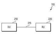
도 2는 기지국의 예를 도시한다. 도 2에서는, 기지국의 기능들이 서로 다른 엔티티들에 의해 나누어져 구현되는 DU와 RU가 서술된다. DU와 RU 간 통신을 위하여, 프론트홀(fronthaul) 인터페이스가 이용될 수 있다. 프론트홀이란, 기지국에서 코어망 사이의 백홀(backhaul)과 달리, 무선랜과 기지국 사이의 엔티티들 사이를 지칭한다. 도 2에서는 DU(210)가 하나의 RU(220) 사이의 프론트홀 구조의 예를 도시하나, 이는 설명의 편의를 위한 것에 불과하며 본 개시가 이에 제한되는 것이 아니다. 다시 말해서, 본 개시의 실시예는 하나의 DU와 복수의 RU들 사이의 프론트홀 구조에도 적용될 수 있다. 예를 들어, 본 개시의 실시예는 하나의 DU와 2개의 RU들 사이의 프론트홀 구조에 적용될 수 있다. 또한, 본 개시의 실시예는 하나의 DU와 3개의 RU들 사이의 프론트홀 구조에도 적용될 수 있다.Figure 2 shows an example of a base station. In Figure 2, DU and RU, in which the functions of the base station are implemented by being divided by different entities, are described. For communication between DU and RU, a fronthaul interface can be used. Fronthaul refers to the connection between entities between the wireless LAN and the base station, unlike backhaul between the base station and the core network. FIG. 2 shows an example of a fronthaul structure between a
도 2를 참고하면, 기지국(110)은 DU(210)와 RU(220)을 포함할 수 있다. DU(210)과 RU(220) 사이의 프론트홀(215)은 Fx 인터페이스를 통해 운용될 수 있다. 프론트홀(215)의 운용을 위해, 예를 들어, eCPRI(enhanced common public radio interface), ROE(radio over ethernet)와 같은 인터페이스가 사용될 수 있다.Referring to FIG. 2, the
통신 기술이 발달함에 따라 모바일 데이터 트래픽이 증가하고, 이에 따라 디지털 유닛과 무선 유닛 사이의 프론트홀에서 요구되는 대역폭 요구량이 크게 증가하였다. C-RAN(centralized/cloud radio access network)와 같은 배치에서, DU는 PDCP(packet data convergence protocol), RLC(radio link control), MAC(media access control), PHY(physical)에 대한 기능들을 수행되고, RU는 RF(radio frequency) 기능에 더하여 PHY 계층에 대한 기능들을 보다 더 수행하도록 구현될 수 있다.As communication technology develops, mobile data traffic increases, and accordingly, the bandwidth requirement for the fronthaul between digital units and wireless units has increased significantly. In deployments such as C-RAN (centralized/cloud radio access network), DU performs functions for PDCP (packet data convergence protocol), RLC (radio link control), MAC (media access control), and PHY (physical). , the RU may be implemented to perform more functions for the PHY layer in addition to the radio frequency (RF) function.
DU(210)는 무선 망의 상위 계층 기능을 담당할 수 있다. 예를 들어, DU(210)는 MAC 계층의 기능, PHY 계층의 일부를 수행할 수 있다. 여기서, PHY 계층의 일부란, PHY 계층의 기능들 중에서 보다 높은 단계에서 수행되는 것으로, 일 예로, 채널 인코딩(혹은 채널 디코딩), 스크램블링(혹은 디스크램블링), 변조(혹은 복조), 레이어 맵핑(layer mapping)(혹은 레이어 디맵핑)을 포함할 수 있다. 일 실시예에 따라, DU(210)가 O-RAN 규격에 따르는 경우, O-DU(O-RAN DU)로 지칭될 수 있다. DU(210)는, 필요에 따라 본 개시의 실시예들에서 기지국(예: gNB)을 위한 제1 네트워크 엔티티로 대체되어 표현될 수 있다.
RU(220)는 무선 망의 하위 계층 기능을 담당할 수 있다. 예를 들어, RU(220)는 PHY 계층의 일부, RF 기능을 수행할 수 있다. 여기서, PHY 계층의 일부란, PHY 계층의 기능들 중에서 DU(210)보다 상대적으로 낮은 단계에서 수행되는 것으로, 일 예로, iFFT 변환(혹은 FFT 변환), CP 삽입(CP 제거), 디지털 빔포밍을 포함할 수 있다. RU(220)는 '액세스 유닛(access unit, AU) ', '액세스 포인트(access point, AP)', '송수신 포인트(transmission/reception point, TRP)', '원격 무선 장비(remote radio head, RRH) ', '무선 유닛(radio unit, RU)' 또는 이와 동등한 기술적 의미를 가지는 다른 용어로 지칭될 수 있다. 일 실시예에 따라, RU(220)이 O-RAN 규격에 따르는 경우, O-RU(O-RAN RU)로 지칭될 수 있다. RU(220)는, 필요에 따라 본 개시의 실시예들에서 기지국(예: gNB)을 위한 제2 네트워크 엔티티로 대체되어 표현될 수 있다.The
도 2에서는 기지국(110)이 DU(210)와 RU(220)를 포함하는 것으로 서술되었으나, 본 개시의 실시예들은 이에 한정되지 않는다. 실시예들에 따른 기지국은 액세스 망의 상위 계층(upper layers)(예: PDCP(packet data convergence protocol), RRC(radio resource control))의 기능을 수행하도록 구성되는 CU(centralized unit)와 하위 계층의 기능을 수행하도록 구성되는 DU(distributed unit)에 따른 분산형 배치(distributed deployment)로 구현될 수 있다. 일 예로, DU(distributed unit)는 도 2의 DU(digital unit)과 RU(radio unit)을 포함할 수 있다. 또한, 일 예로, 코어(예: 5GC(5G core) 혹은 NGC(next generation core)) 망과 무선망(RAN) 사이에서, 기지국은 CU, DU, RU 순으로 배치되는 구조로 구현될 수 있다. CU와 DU(distributed unit) 간 인터페이스는 F1 인터페이스로 지칭될 수 있다.In FIG. 2, the
CU(centralized unit)는 하나 이상의 DU들과 연결되어, DU보다 상위 계층의 기능을 담당할 수 있다. 예를 들어, CU는 RRC(radio resource control) 및 PDCP(packet data convergence protocol) 계층의 기능을 담당하고, DU와 RU가 하위 계층의 기능을 담당할 수 있다. DU는, RLC(radio link control), MAC(media access control), PHY(physical) 계층의 일부 기능들(high PHY)을 수행하고, RU는 PHY 계층의 나머지 기능들(low PHY)을 담당할 수 있다. 또한, 일 예로, DU(digital unit)는 기지국의 분산형 배치 구현에 따라, DU(distributed unit)에 포함될 수 있다. 이하, 별도의 정의가 없는 한 DU(digital unit)와 RU의 동작들로 서술되나, 본 개시의 다양한 실시예들은, CU를 포함하는 기지국 배치 혹은 DU가 직접 코어망과 연결되는 배치(즉, CU와 DU가 하나의 엔티티인 기지국(예: NG-RAN node)로 통합되어 구현) 모두에 적용될 수 있다.A centralized unit (CU) is connected to one or more DUs and can be responsible for functions of a higher layer than the DU. For example, the CU may be responsible for the functions of the radio resource control (RRC) and packet data convergence protocol (PDCP) layers, and the DU and RU may be responsible for the functions of the lower layer. DU performs RLC (radio link control), MAC (media access control), and some functions of the PHY (physical) layer (high PHY), and RU is responsible for the remaining functions of the PHY layer (low PHY). there is. Additionally, as an example, a digital unit (DU) may be included in a distributed unit (DU), depending on the distributed deployment implementation of the base station. Hereinafter, unless otherwise defined, the operations of a digital unit (DU) and RU are described, but various embodiments of the present disclosure are based on a base station arrangement including a CU or an arrangement where the DU is directly connected to the core network (i.e., CU and DU can be applied to both integrated and implemented as a single entity, a base station (e.g., NG-RAN node).
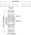
도 3은 시간 영역 및 주파수 영역에서 자원 구조의 예를 도시한다. 도 3은 하향링크 또는 상향링크에서 데이터 또는 제어 채널이 전송되는 무선 자원 영역인 시간-주파수 영역의 기본 구조를 예시한다.Figure 3 shows an example of a resource structure in the time domain and frequency domain. Figure 3 illustrates the basic structure of the time-frequency domain, which is a radio resource domain in which data or control channels are transmitted in downlink or uplink.
도 3을 참고하면, 가로 축은 시간 영역을, 세로 축은 주파수 영역을 나타낸다. 시간 영역에서의 최소 전송단위는 OFDM(orthogonal frequency division multiplexing) 심볼로서, Nsymb개의 OFDM 심볼들(302)이 모여 하나의 슬롯(306)을 구성한다. 서브프레임의 길이는 1.0ms으로 정의되고, 라디오 프레임(radio frame)(314)의 길이는 10ms로 정의된다. 주파수 영역에서의 최소 전송 단위는 부반송파(subcarrier)로서, 자원 그리드(resource grid)를 구성하는 캐리어 대역폭(carrier bandwidth)은 NBW개의 부반송파들(304)로 구성된다.Referring to Figure 3, the horizontal axis represents the time domain and the vertical axis represents the frequency domain. The minimum transmission unit in the time domain is an orthogonal frequency division multiplexing (OFDM) symbol, and Nsymb OFDM symbols 302 are gathered to form one slot 306. The length of the subframe is defined as 1.0 ms, and the length of the radio frame 314 is defined as 10 ms. The minimum transmission unit in the frequency domain is a subcarrier, and the carrier bandwidth constituting the resource grid is composed of NBW subcarriers 304.
시간-주파수 영역에서 자원의 기본 단위는 자원 요소(resource element, 이하 'RE')(312)로서, OFDM 심볼 인덱스 및 부반송파 인덱스로 나타낼 수 있다. 자원 블록은 복수 개의 자원 요소들을 포함할 수 있다. LTE 시스템에서, 자원 블록(resource block, RB)(또는 물리적 자원 블록(physical resource block, 이하 'PRB'))은 시간 영역에서 Nsymb개의 연속된 OFDM 심볼들 및 주파수 영역에서 NSCRB개의 연속된 부반송파들로 정의된다. NR 시스템에서, 자원 블록(RB)(308)은 주파수 영역에서 NSCRB개의 연속된 부반송파들(310) 로 정의될 수 있다. 하나의 RB(308)는 주파수 축에서, NSCRB 개의 RE(312)들을 포함한다. 일반적으로 데이터의 최소 전송단위는 RB이고 서브캐리어들의 개수 NSCRB=12 이다. 주파수 영역은 공통 자원 블록(common resource block, CRB)들을 포함할 수 있다. 주파수 영역 상의 대역폭 부분(bandwidth part, BWP)에서 물리적 자원 블록(PRB)이 정의될 수 있다. CRB 및 PRB 번호는 서브캐리어 간격(subcarrier spacing)에 따라 결정될 수 있다. 단말에게 스케줄링되는 RB들의 개수에 비례하여 데이터 전송률(data rate)이 증가할 수 있다.The basic unit of resources in the time-frequency domain is a resource element (hereinafter 'RE') 312, which can be represented by an OFDM symbol index and a subcarrier index. A resource block may include multiple resource elements. In the LTE system, a resource block (RB) (or physical resource block (PRB) hereinafter) consists of Nsymb consecutive OFDM symbols in the time domain and NSCRB consecutive symbols in the frequency domain. Defined as subcarriers. In the NR system, a resource block (RB) 308 can be defined as NSCRB consecutive subcarriers 310 in the frequency domain. One RB 308 includes NSCRB REs 312 in the frequency axis. Generally, the minimum transmission unit of data is RB and the number of subcarriers is NSCRB = 12. The frequency domain may include common resource blocks (CRBs). A physical resource block (PRB) may be defined in the bandwidth part (BWP) in the frequency domain. CRB and PRB numbers may be determined according to subcarrier spacing. The data rate may increase in proportion to the number of RBs scheduled for the UE.
NR 시스템에서, 하향링크와 상향링크를 주파수로 구분하여 운영하는 FDD(frequency division duplex) 시스템의 경우, 하향링크 전송 대역폭과 상향링크 전송 대역폭이 서로 다를 수 있다. 채널 대역폭은 시스템 전송 대역폭에 대응되는 RF(radio frequency) 대역폭을 나타낸다. [표 1]은 x GHz 보다 낮은 주파수 대역(예: FR(frequency range) 1(310 MHz ~ 7125 MHz))에서의 NR 시스템에 정의된 시스템 전송 대역폭, 부반송파 간격(subcarrier spacing, SCS)과 채널 대역폭(channel bandwidth)의 대응관계의 일부를 나타낸다. 그리고 [표 2]는 yGHz 보다 높은 주파수 대역(예: FR2(24250 MHz - 52600 MHz) 혹은 FR2-2(52600 MHz ~ 71000 MHz))에서의 NR 시스템에 정의된 전송 대역폭, 부반송파 간격, 및 채널 대역폭의 대응관계의 일부를 나타낸다. 예를 들어, 30 kHz 부반송파 간격으로 100 MHz 채널 대역폭을 갖는 NR 시스템은 전송 대역폭이 273개의 RB들로 구성된다. [표 1] 및 [표 2]에서 N/A는 NR 시스템에서 지원하지 않는 대역폭-부반송파 조합일 수 있다.In the NR system, in the case of a frequency division duplex (FDD) system that operates by dividing the downlink and uplink by frequency, the downlink transmission bandwidth and the uplink transmission bandwidth may be different. The channel bandwidth represents the RF (radio frequency) bandwidth corresponding to the system transmission bandwidth. [Table 1] shows the system transmission bandwidth, subcarrier spacing (SCS), and channel bandwidth defined for the NR system in a frequency band lower than x GHz (e.g., FR (frequency range) 1 (310 MHz ~ 7125 MHz)). It represents part of the correspondence relationship of (channel bandwidth). And [Table 2] shows the transmission bandwidth, subcarrier spacing, and channel bandwidth defined in the NR system in a frequency band higher than yGHz (e.g., FR2 (24250 MHz - 52600 MHz) or FR2-2 (52600 MHz ~ 71000 MHz)). It represents part of the correspondence relationship between . For example, an NR system with a 100 MHz channel bandwidth at 30 kHz subcarrier spacing has a transmission bandwidth of 273 RBs. In [Table 1] and [Table 2], N/A may be a bandwidth-subcarrier combination that is not supported by the NR system.
[MHz]channel bandwidth
[MHz]
SCS
NRBConfigure transfer bandwidth
NR B
[MHz]channel bandwidth
[MHz]
NRBConfigure transfer bandwidth
NR B
도 4는 통신 규격에서 채널들(channels)의 예를 도시한다.Figure 4 shows examples of channels in a communication standard.
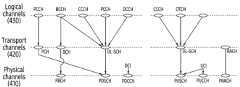
도 4는 통신 규격에서 채널들(channels)의 예를 도시한다. 상기 채널들은 통신 규격에서 정의되는 계층들에 따라, 물리 채널(physical channel)(410), 전송 채널(transport channel)(420), 및 논리 채널(logical channel)(430)을 포함할 수 있다.Figure 4 shows examples of channels in a communication standard. The channels may include a
도 4를 참고하면, 물리 채널(410)은 물리 계층에서 물리 신호들(physical signal)을 생성하기 위해 필요한 기능들(예: 채널코딩, HARQ 프로세싱, 변조, 다중 안테나 프로세싱, 자원 매핑)을 제공할 수 있다. 물리 계층에서, 물리 신호들은 OFDM 방식으로 변조되며, 시간-주파수 자원(예: 도 3의 자원 그리드의 자원)을 통해 무선 환경에서 전송될 수 있다.Referring to FIG. 4, the
하향링크 전송에서 물리 채널(410)은 PBCH(physical broadcast channel), PDSCH(physical downlink shared channel), 또는 PDCCH(physical downlink control channel) 중 적어도 하나를 포함할 수 있다. PDCCH는 DCI(downlink control information)를 운반하기 위해 이용될 수 있다. 일반적으로 하향링크 데이터는 PDSCH를 통해 전송되는 심볼들을 지칭하고, 하향링크 제어 신호는 PDCCH를 통해 전송되는 심볼들을 포함할 수 있다. 또한, 하향링크에서, 도 4에 도시된 채널들 외에, 동기화를 위해 동기 신호(예: PSS(primary synchronization signal), SSS(secondary synchronization signal)와 방송 신호(예: PBCH)를 포함하는 SS/PBCH 블록이 전송될 수 있다. 또한, 하향링크에서, 측정(measurement) 혹은 채널 정보를 획득하기 위한 CSI-RS(channel state information-reference signal), 채널 추정 및 복조를 위한 DMRS(demodulation reference signal), 및 PTRS(phase tracking reference signal)이 하향링크에서 전송될 수 있다.In downlink transmission, the
상향링크 전송에서 물리 채널(410)은 PUSCH(physical uplink shared channel), PUCCH(physical uplink control channel), 또는 PRACH(physical random access channel) 중 적어도 하나를 포함할 수 있다. PUSCH 또는 PUCCH는 UCI(uplink control information)을 운반하기 위해 이용될 수 있다. 일반적으로 상향링크 데이터는 PUSCH를 통해 전송되는 심볼들을 지칭하고, 상향링크 제어 신호는 UCI에 대응하는 심볼들을 포함할 수 있다. 예를 들어, UCI는 SR(scheduling request), HARQ(hybrid automatic request)-ACK(acknowledge) 비트(들), 또는 CSI(channel state information) 중 적어도 하나를 포함할 수 있다. 또한, 상향링크에서, 도 4에 도시된 채널들 외에, 채널 추정을 위해, 채널 추정 및 복조를 위한 DMRS 및 PTRS가 하향링크에서 전송될 수 있다.In uplink transmission, the
전송 채널(420)은, 물리 계층과 상기 물리 계층의 상위 레벨에 위치한 MAC(medium access channel) 계층을 연결하며, 무선 인터페이스를 통해 데이터가 어떻게 전송되는지에 따라 구분될 수 있다. 하향링크에서 전송 채널(420)은, 페이징을 위한 PCH(paging channel), 시스템 정보의 방송을 위한 BCH(broadcast channel), 또는 하향링크 데이터의 전송을 위한 DL-SCH(downlink shared channel) 중 적어도 하나를 포함할 수 있다. 상향링크에서 전송 채널(420)은, 랜덤 액세스 프리앰블의 전송을 위한 RACH(random access channel) 또는 하향링크 데이터의 전송을 위한 UL-SCH(uplink shared channel) 중 적어도 하나를 포함할 수 있다.The
논리 채널(430)은 전송 채널의 상위에 있으며, 전송 채널(420)에 맵핑된다. 논리 채널(430)은 제어 영역 정보의 전달을 위한 제어 채널과 사용자 영역 정보의 전달을 위한 트래픽 채널로 구분될 수 있다. 논리 채널(430)의 제어 채널은 PCCH(paging control channel), BCCH(broadcast control channel), CCCH(common control channel), 또는 DCCH(dedicated control channel) 중 적어도 하나를 포함할 수 있다. 논리 채널(430)의 트래픽 채널은 DTCH(dedicated traffic channel)을 포함할 수 있다.The
본 개시의 실시예들을 설명함에 있어, 랜덤 액세스 신호는 PRACH(physical random access channel)를 통해 전달되는 시퀀스들을 포함할 수 있다. '데이터'는 기준 신호(reference signal)가 아닌 신호들을 포함할 수 있다. 일 예로, 상향링크 통신에서 수신기에 의해 획득되는'데이터'는 PUSCH를 통해 전달되는 신호들을 포함할 수 있다. 그러나, PUSCH는 예시적인 것이며, 채널 추정(channel estimation)을 필요로 하는 다른 채널들(예: PDSCH, PBCH, PDCCH, PUCCH)에도 본 개시의 실시예들이 적용될 수 있음은 물론이다.In describing embodiments of the present disclosure, a random access signal may include sequences transmitted through a physical random access channel (PRACH). 'Data' may include signals other than a reference signal. As an example, 'data' acquired by a receiver in uplink communication may include signals transmitted through PUSCH. However, PUSCH is an example, and of course, embodiments of the present disclosure can be applied to other channels that require channel estimation (eg, PDSCH, PBCH, PDCCH, PUCCH).
도 5는 PUSCH(physical uplink shared channel) 전송에 대한 간섭(interference)의 예를 도시한다. DMRS는 데이터를 복조하기 위해 이용되는 기준 신호(reference signal, RS)이다. 데이터(예: PDSCH, PUSCH)를 복조하기 위해 채널을 추정하고, 채널 추정의 결과를 얻기 위하여, DMRS가 이용될 수 있다. 이하, 본 개시의 채널 추정과 채널 추정을 위한 DMRS를 이용한 동작들을 설명하기 위하여, NR 통신 시스템의 상향링크 전송이 예로 서술된다. 그러나, 본 개시의 실시예들이 NR 통신 시스템의 상향링크로 제한되는 것은 아니다. 하향링크 혹은 다른 통신 시스템에서도 본 개시의 실시예들이 적용될 수 있음은 물론이다.Figure 5 shows an example of interference for physical uplink shared channel (PUSCH) transmission. DMRS is a reference signal (RS) used to demodulate data. DMRS can be used to estimate a channel to demodulate data (e.g., PDSCH, PUSCH) and obtain the result of channel estimation. Hereinafter, to explain channel estimation of the present disclosure and operations using DMRS for channel estimation, uplink transmission of the NR communication system is described as an example. However, embodiments of the present disclosure are not limited to the uplink of the NR communication system. Of course, embodiments of the present disclosure can be applied to downlink or other communication systems.
도 5를 참고하면, 기지국(예: 기지국(110))은 단말(예: 단말(120))로부터 신호를 수신할 수 있다. 단말(120)은 기지국(110)에게 상향링크 신호를 전송할 수 있다. 상기 수신된 신호는 상향링크 채널(예: PUSCH) 상에서 수신되는 데이터(이하, 수신 데이터)를 포함할 수 있다. 상기 수신 데이터는 시간 도메인(time domain)의 데이터 심볼들에서 전송될 수 있다. 또한, 상기 수신된 신호는 상기 데이터 심볼들의 채널 추정 및 코히어런트 복조(coherent demodulation)를 위한 기준 신호들(이하, 수신 기준 신호들)(예: DMRS)을 포함할 수 있다. 상기 수신 기준 신호들은 시간 도메인(time domain)의 DMRS 심볼들에서 전송될 수 있다. 기지국(110)은 단말(120)으로부터, 슬롯(slot)의 상기 데이터 심볼들에서 상기 수신 데이터를 수신하고 및 상기 DMRS 심볼들에서 상기 수신 기준 신호들을 수신할 수 있다. 슬롯은 14개의 심볼들(예: 심볼 #0(500), 심볼 #1(501), 심볼 #2(502), 심볼 #3(503), 심볼 #4(504), 심볼 #5(505), 심볼 #6(506), 심볼 #7(507), 심볼 #8(508). 심볼 #9(509), 심볼 #10(510), 심볼 #11(511), 심볼 #12(512), 및 심볼 #13(513))을 포함할 수 있다. 상기 14개의 심볼들 중에서 적어도 일부 심볼은 DMRS 시퀀스들을 운반하기 위해 이용될 수 있다. 예를 들어, 심볼 #2(502)의 구간 및 심볼 #11(511)의 구간은 DMRS 심볼들을 포함할 수 있다.Referring to FIG. 5, a base station (e.g., base station 110) may receive a signal from a terminal (e.g., terminal 120). The terminal 120 may transmit an uplink signal to the
기지국(110)은 수신 기준 신호들을 통해 기지국(110)과 단말(120) 간 채널을 추정할 수 있다. 기지국(110)은, 상기 수신 기준 신호들이 겪는 채널에 대한 정보를 획득할 수 있다. 예를 들어, 기지국(110)은, 상기 수신 기준 신호들의 DMRS 심볼들이 맵핑되는 위치와 상기 수신 데이터의 데이터 심볼들이 맵핑되는 위치들 간의 관계를 통해, 상기 수신 데이터가 겪은 채널에 대한 정보를 획득할 수 있다. 일 예로, 기지국(110)은 상기 수신 기준 신호들이 겪는 채널에 대한 정보를 기초로, 주파수 도메인에서의 보간(interpolation)이나 시간 도메인에서의 보간을 수행함으로써, 상기 수신 데이터가 겪은 채널에 대한 정보를 획득할 수 있다. 그러나, 전송 단위인 하나의 슬롯 내에서 데이터 심볼들의 개수는 일반적으로 DMRS 심볼들의 개수보다 많기 때문에, 데이터 심볼들 각각이 겪는 채널을 추정하는 동작은 많은 연산량을 요구할 수 있다. 뿐만 아니라, DMRS 심볼들 자체에 대한 연산이나 셀 간 간섭을 반영하지 못하므로, 수신 성능이 보장되지 않을 수 있다. 이를 위해, 수신단인 기지국(110)은 다양한 수신 기법들을 활용할 수 있다.The
본 개시의 실시예들은, 다양한 패턴들을 갖는 간섭 환경에서 PUSCH의 수신 성능을 개선하기 위한 수신기에 관한 것이다. 수신기의 채널 추정 블록을 포함하는 네트워크 엔티티(예: 기지국(110), DU(210), RU(220))는 DMRS 심볼들(예: 심볼 #2(502), 심볼 #11(511))에 기반하여, 잡음 성분(component)과 간섭 성분(component)의 자기-공분산 행렬(auto-covariance matrix)(이하, 잡음-간섭(noise-interference) 공분산 행렬(covariance matrix))을 추정할 수 있다. 예를 들어, 상기 수신기는 MMSE(minimum mean square error) 수신기를 포함할 수 있다.Embodiments of the present disclosure relate to a receiver for improving reception performance of PUSCH in an interference environment with various patterns. A network entity (e.g.,
송신 신호와 상기 수신 신호의 관계는 하기와 같이 표현될 수 있다.The relationship between the transmitted signal and the received signal can be expressed as follows.
y는 수신 신호,H는 송신단과 수신단 간의 채널,x는 송신 신호,i는 간섭 성분,n은 잡음 성분을 나타낸다.y represents the received signal,H represents the channel between the transmitting end and the receiving end,x represents the transmitted signal,i represents the interference component, andn represents the noise component.
DMRS의 수신 신호와 sequence, 채널에 기반하여 NI(noise and interference)가 추정될 수 있다. 상기 NI는 상기 잡음-간섭 공분산 행렬에 대응할 수 있다. 예를 들어, 상기 잡음-간섭 공분산 행렬은 하기의 수학식으로 표현될 수 있다.Received signal from DMRS and sequence , channel Based on , noise and interference (NI) can be estimated. The NI may correspond to the noise-interference covariance matrix. For example, the noise-interference covariance matrix can be expressed as the following equation.
DMRS의 수신 신호와 송신 신호, 채널에 기반하여 NI(noise and interference)가 추정될 수 있다. 상기 NI는 상기 잡음-간섭 공분산 행렬에 대응할 수 있다. 예를 들어, 상기 잡음-간섭 공분산 행렬은 하기의 수학식으로 표현될 수 있다.Received signal from DMRS and transmit signal , channel Based on , noise and interference (NI) can be estimated. The NI may correspond to the noise-interference covariance matrix. For example, the noise-interference covariance matrix can be expressed as the following equation.
잡음 성분 및 간섭 성분의 추정의 정확도를 높이기 위해 복수의 시간-주파수 자원들, DMRS들에 기반하여, 하나의 잡음-간섭 공분산 행렬(즉, Rnn값)이 획득될 수 있다. 이 때 인접 RB 혹은 인접 심볼 간에 잡음 성분과 간섭 성분(이하, 잡음-간섭 성분 또는 NI 성분)이 유사하다는 가정하에, 평균 연산은 하나의 잡음-간섭 공분산 행렬을 얻기 위해 이용될 수 있다.To increase the accuracy of estimation of noise and interference components, one noise-interference covariance matrix (i.e., Rnn value) can be obtained based on a plurality of time-frequency resources and DMRSs. At this time, under the assumption that the noise component and interference component (hereinafter, noise-interference component or NI component) are similar between adjacent RBs or adjacent symbols, average operation can be used to obtain one noise-interference covariance matrix.
슬롯 내에서 특정 RB 또는 특정 심볼에 간섭이 들어오는 환경을 가정하자. 예를 들어, 심볼 #9(509), 심볼 #10(510), 심볼 #11(511), 심볼 #12(512), 및 심볼 #13(513)에 걸쳐 다른 신호(예: PUCCH) 혹은 다른 셀의 신호(예: 다른 셀의 미니-슬롯(mini-slot))로 인해, 간섭(520)이 발생할 수 있다. 인접 RB 혹은 인접 심볼 간 잡음-간섭 성분이 유사하다는 가정이 성립하지 않을 수 있다. 또한, 간섭 신호로 인해 추정된 NI가 널링(nulling) 되지 않으므로, 수신기의 성능이 열화된다. 이러한 열화를 방지하기 위해, 동일한 잡음-간섭 성분이 가정되는 자원 영역을 보다 작게 설정할 수 있다. 그러나, 수신기는 어느 자원(예: RE)에 간섭 성분이 있는지 정확히 알 수 없으므로, 작게 설정되는 자원 영역을 통해 추정되는 잡음-간섭 성분은 정확하지 않을 수 있다. 또한, 상기 자원 영역이 크게 설정된다면, 다른 셀에서의 간섭이나 다른 채널의 신호로 인한 간섭으로 인해, 추정되는 잡음-간섭 성분은 정확하지 않을 수 있다. 간섭이 들어온 RE 및 간섭이 없는 RE 모두 동일한 잡음-간섭 성분이 적용되기 때문이다.Let us assume an environment in which interference occurs in a specific RB or a specific symbol within a slot. For example, another signal (e.g., PUCCH) or
상술된 문제들을 보완하기 위해, 본 개시에서는 간섭 환경에서 간섭 유무를 판별하여, 간섭 환경에 적합한 잡음-공분산 행렬을 추정하기 위한 기술을 제안한다. 간섭의 유무란, 수신기의 수신 성능에 영향을 미치는 정도의 간섭이 존재하는지 여부를 의미한다. 예를 들어, 상향링크 신호(예: PUSCH)를 수신()하는 수신기의 결합기(combiner)(예: MMSE 결합기)를 가정하자. MMSE 결합기의 출력()은 다음과 같다.In order to complement the problems described above, the present disclosure proposes a technique for determining the presence or absence of interference in an interference environment and estimating a noise-covariance matrix suitable for the interference environment. The presence or absence of interference refers to whether there is a level of interference that affects the reception performance of the receiver. For example, receiving an uplink signal (e.g. PUSCH) ( ) Let's assume a receiver's combiner (e.g., MMSE combiner). The output of the MMSE combiner ( )Is as follows.
Rnn은 잡음-간섭 공분산 행렬, W는 MMSE 결합기의 가중치를 나타낸다.Rnn represents the noise-interference covariance matrix, and W represents the weight of the MMSE combiner.
잘 추정된은 잡음 성분과 간섭 성분을 널링함으로써, 높은 수신 성능을 제공할 수 있다.은 기준 신호들에 기반하여 추정될 수 있다. 추정 정확도를 높이기 위해, 평균 연산(E{})가 이용될 수 있다. 상기 평균 연산은 상기 기준 신호들이 맵핑되는 적어도 하나의 심볼 및 적어도 하나의 RB에 걸쳐 수행될 수 있다. 예를 들어,은 수학식 2에 기반하여 추정될 수 있다.well estimated Can provide high reception performance by nulling noise and interference components. can be estimated based on reference signals. To increase estimation accuracy, the averaging operation (E {}) can be used. The average calculation may be performed over at least one symbol and at least one RB to which the reference signals are mapped. for example, can be estimated based on Equation 2.
수신 신호 는 이웃 셀의 간섭를 포함할 수 있다. 간섭 신호가 할당된 자원(예: 심볼, RB)에 전체적으로 들어가 있다면, 평균 연산을 통해 획득되는 Rnn은 최적의 성능을 제공할 수 있다. 그러나, 슬롯 내에서 일부 영역(예: 미니-슬롯)에만 간섭 신호가 있을 경우, 상기 자원 영역의 잡음-간섭 성분이 상기 간섭 신호가 없는 자원 영역에 영향을 미친다. 이러한 영향은, 간섭 신호가 없는 자원 영역에 불필요한 널링을 제공하고, 간섭 신호가 있는 자원 영역에는 정확하지 않은 간섭 널링을 제공한다. 즉, 간섭 신호가 수신 신호의 국소 영역(local area)에 존재하는 경우, 상기 평균 연산을 통해 획득된 Rnn에 따른 채널 추정은 오히려 수신기의 성능 저하를 야기한다. 따라서, 본 개시의 실시예들에서는, 간섭 영향을 받는 영역에서는 평균 연산을 통해 Rnn을 얻는 대신, 인접한 RS의 Rnn에 기반하여, 해당 데이터 심볼의 채널 추정을 수행하는 전자 장치 및 방법이 제안된다.receiving signal is interference from neighboring cells may include. If the interference signal is entirely contained in the allocated resources (e.g., symbol, RB), Rnn obtained through averaging operation can provide optimal performance. However, if there is an interference signal only in some areas (eg, mini-slot) within the slot, the noise-interference component of the resource area affects the resource area without the interference signal. This effect provides unnecessary nulling in resource areas without interference signals and provides inaccurate interference nulling in resource areas with interference signals. That is, when an interference signal exists in the local area of the received signal, channel estimation according to Rnn obtained through the average operation actually causes performance degradation of the receiver. Therefore, in embodiments of the present disclosure, instead of obtaining Rnn through average calculation in an area affected by interference, an electronic device and method for performing channel estimation of a corresponding data symbol based on Rnn of an adjacent RS are proposed. do.
도 6a 내지 도 6b는 간섭 여부를 식별하기 위한 간섭 팩터의 예들을 도시한다. 상기 간섭 팩터는 잡음-간섭 공분산 행렬에 기반하여 결정될 수 있다. 상기 간섭 팩터는 화이트닝 팩터(whitening factor) 혹은 OAS(oracle approximating shrinkage)를 포함할 수 있다.6A to 6B show examples of interference factors for identifying interference. The interference factor may be determined based on a noise-interference covariance matrix. The interference factor may include a whitening factor or oracle approximating shrinkage (OAS).
도 6a를 참고하면, 그래프(600)는 간섭 신호가 없는 환경(601)(예: INR(interference to noise ratio) -30dB(decibel))과 간섭 신호가 있는 환경(602)(예: INR 10dB) 각각에서 화이트닝 팩터의 분포(예: PDF(probability density function))를 나타낸다. 그래프(600)의 x축은 화이트닝 팩터(whiteness factor)를 나타내고, 그래프(600)의 y축은 환경(601) 및 환경(602) 각각에서의 x축에 해당하는 화이트닝 팩터를 가질 확률을 나타낸다.Referring to FIG. 6A, the graph 600 shows an environment 601 without an interference signal (e.g., interference to noise ratio (INR) -30 dB (decibel)) and an environment 602 with an interference signal (e.g.,
화이트닝 팩터는 잡음-간섭 공분산 행렬에 기반하여 결정될 수 있다. 화이트닝 팩터는 상기 잡음-간섭 공분산 행렬의 대각 성분 및 상기 잡음-간섭 공분산 행렬의 노름(norm) 정보에 기반하여 결정될 수 있다. 예를 들어, 상기 화이트닝 팩터는 하기의 수학식에 기반하여 결정될 수 있다.The whitening factor can be determined based on the noise-interference covariance matrix. The whitening factor may be determined based on the diagonal component of the noise-interference covariance matrix and the norm information of the noise-interference covariance matrix. For example, the whitening factor can be determined based on the following equation.
는 기준 신호(rs) 및 특정 자원(RB)에서 화이트닝 팩터를 나타낸다.은 기준 신호(rs) 및 특정 자원(RB)에서 잡음-간섭 공분산 행렬을 나타낸다. 기준 신호(rs)는 슬롯 내 심볼(예: 심볼 #2(502), 심볼 #11(511))에 대응할 수 있다.는 상기 노름 정보에 대응한다. 예를 들어,는 수학식 5에따른 행렬의 프로베니우스 노름(Frobenius norm)를 나타낸다.는 상기 대각 성분의 크기에 대응한다. 예를 들어,는 수학식 6에 따른 행렬의 트레이스(trace)를 나타낸다. N은 행렬의 크기, 즉, 수신기의 수신 안테나들의 개수를 나타낸다.represents the whitening factor in the reference signal (rs) and the specific resource (RB). represents the noise-interference covariance matrix in the reference signal (rs) and the specific resource (RB). The reference signal (rs) may correspond to a symbol within a slot (e.g., symbol #2 (502), symbol #11 (511)). corresponds to the above gambling information. for example, According to Equation 5, procession It represents the Frobenius norm of . corresponds to the size of the diagonal component. for example, is according to equation 6 procession Shows the trace. N is It represents the size of the matrix, that is, the number of receiving antennas of the receiver.
는 행렬의 i번째 행 및 j번째 열에 대응하는 요소(element)를 나타낸다.is a matrix Indicates the element corresponding to the i-th row and j-th column.
수학식 4에 따른, 화이트닝 팩터는 아래와 같은 범위를 가질 수 있다.According to
예를 들어, 간섭이 없는 항등 행렬(identity matrix)에서, 화이트닝 팩터는의 값을 가질 수 있다. 한편, 간섭 신호가 크다면, 그래프(600)에 도시된 바와 같이, 비대각 성분(off-diagonal term)의 영향이 커지므로(상대적으로 대각 성분의 영향이 작아지므로), 화이트닝 팩터는 1에 가까운 값을 가질 수 있다.For example, in an interference-free identity matrix, the whitening factor is It can have a value of . On the other hand, if the interference signal is large, as shown in the graph 600, the influence of the off-diagonal term increases (since the influence of the diagonal term becomes relatively small), and the whitening factor is close to 1. It can have a value.
도 6b를 참고하면, 그래프(650)는 OAS의 PDF(probability density function)을 나타낸다. 그래프(650)는 간섭 신호가 없는 환경(651)에 대한 OAS 값의 분포(예: PDF)와 간섭 신호가 있는 환경(652)(예: INR 10dB)에 대한 OAS 값의 분포를 나타낸다. 그래프(650)의 x축은 OAS 값을 나타내고, 그래프(650)의 y축은 환경(651) 및 환경(652) 각각에서의 x축에 해당하는 OAS 값을 가질 확률을 나타낸다.Referring to FIG. 6B, a graph 650 represents the probability density function (PDF) of OAS. The graph 650 shows the distribution of OAS values (eg, PDF) for an environment 651 without an interference signal and the distribution of OAS values for an environment 652 with an interference signal (eg,
OAS 값은 잡음-간섭 공분산 행렬에 기반하여 결정될 수 있다. OAS 값은 상기 잡음-간섭 공분산 행렬의 대각 성분, 상기 잡음-간섭 공분산 행렬의 노름 정보, 수신기의 수신 안테나들의 개수, 및 샘플들의 개수에 기반하여 결정될 수 있다. 예를 들어, 상기 OAS 값은 하기의 수학식에 기반하여 결정될 수 있다.The OAS value can be determined based on the noise-interference covariance matrix. The OAS value may be determined based on the diagonal component of the noise-interference covariance matrix, norm information of the noise-interference covariance matrix, the number of receiving antennas of the receiver, and the number of samples. For example, the OAS value can be determined based on the following equation.
은 기준 신호(rs) 및 특정 자원(RB)에서 OAS 값을 나타낸다. n은 Rnn계산 시 누적한 샘플들의 개수를 나타낸다. 예를 들어, Rnn계산을 위해, 중심 극한 정리(central limit theorem)에 따라, n은 2 RB에 대응하는 샘플들의 개수 이상일 수 있다.는 상기 노름 정보에 대응한다.는 상기 대각 성분의 크기에 대응한다. N은 수신 안테나들의 개수를 나타낸다.represents the OAS value in the reference signal (rs) and specific resource (RB). n represents the number of samples accumulated when calculating Rnn . For example, for Rnn calculation, according to the central limit theorem, n may be more than the number of samples corresponding to 2 RB. corresponds to the above gambling information. corresponds to the size of the diagonal component. N represents the number of receiving antennas.
수학식 8에 따른 OAS 값은 0 이상일 수 있다. 항등 행렬의 OAS 값은 1보다 클 수 있다(예:). 한편, 간섭 신호가 크다면, 대각 성분의 영향이 작아지므로, 그래프(650)에 도시된 바와 같이, OAS 값은 0에 가까운 값을 가질 수 있다.The OAS value according to
그래프(600) 및 그래프(650)에 도시된 바와 같이, 수신 신호에 포함되는 간섭 신호로 인한 영향에 따라, 간섭 팩터는 서로 다른 분포를 갖는다. 상기 간섭 팩터의 분포에 기반하여, 평균 연산을 통해 Rnn을 통해 데이터 심볼의 채널 추정을 수행할지 혹은 인접한 RS의 Rnn을 통해 데이터 심볼의 채널 추정을 수행할지 여부가 결정될 수 있다. 도 6a 내지 도 6b에서는 화이트닝 팩터 및 OAS 값이 간섭의 영향을 판단하기 위한 파라미터로 예시되었으나, 본 개시의 실시예들은 이에 한정되지 않는다. 상술된 간섭 팩터들 외에 동일 또는 유사한 기술적 의미를 갖는 다른 파라미터가, 간섭 신호의 영향이 있는지 여부를 식별하기 위해 이용될 수 있음은 물론이다. 예를 들어, 간섭의 세기(이하, 간섭 레벨)를 위한 파라미터를 통해 간섭 신호의 영향이 판단될 수 있다. 일 예로, 잡음-간섭 공분산 행렬의 대각 성분의 크기, 즉, 트레이스 값인에 기반하여, 데이터 심볼에 간섭 신호로 인한 영향이 있는지 여부가 결정될 수 있다.As shown in graph 600 and graph 650, the interference factor has different distributions depending on the influence of the interference signal included in the received signal. Based on the distribution of the interference factor, it can be determined whether to perform channel estimation of the data symbol through Rnn or through Rnn of the adjacent RS through average calculation. 6A to 6B, the whitening factor and the OAS value are illustrated as parameters for determining the effect of interference, but embodiments of the present disclosure are not limited thereto. Of course, in addition to the above-described interference factors, other parameters with the same or similar technical meaning can be used to identify whether there is an influence of an interference signal. For example, the impact of an interference signal can be determined through a parameter for the intensity of interference (hereinafter referred to as interference level). As an example, the size of the diagonal component of the noise-interference covariance matrix, that is, the trace value, Based on , it can be determined whether there is an effect on the data symbol due to the interference signal.
이하, 상기 간섭 팩터에 기반하여 데이터 심볼의 채널 추정을 위한 Rnn을 선택하기 위한 기능 블록들이 서술된다Hereinafter, functional blocks for selecting Rnn for channel estimation of data symbols based on the interference factor are described.
도 7a 내지 도 7b는 잡음-간섭 공분산 행렬을 적응적으로 선택하기 위한 기능 블록들의 예를 도시한다. 각 기능 블록은 수신기에 대응하는 네트워크 엔티티(예: 기지국(110), DU(210), RU(220))에서의 동작으로 이해될 수 있다. 이하 사용되는 '...부', '...기' 등의 용어는 적어도 하나의 기능이나 동작을 처리하는 단위를 의미하며, 이는 하드웨어나 소프트웨어, 또는, 하드웨어 및 소프트웨어의 결합으로 구현될 수 있다.7A-7B show examples of functional blocks for adaptively selecting a noise-interference covariance matrix. Each functional block can be understood as an operation in a network entity (eg,
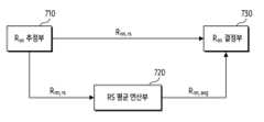
도 7a를 참고하면, 수신기는 Rnn 추정부(710), RS 평균 연산부(720), 및 Rnn 결정부(730)를 포함할 수 있다. Rnn 추정부(710)는 DMRS 심볼(예: 심볼 #2(502), 심볼 #11(511))에 대응하는 잡음-간섭 공분산 행렬(Rnn)을 추정할 수 있다. 예를 들어, Rnn 추정부(710)는 수학식 2에 기반하여, DMRS 심볼에 대응하는 시간 구간(예: 심볼(rs)) 및 RB에 따른 주파수 영역에서 잡음-간섭 공분산 행렬(Rnn)을 추정할 수 있다. 예를 들어, Rnn 추정부(710)는 심볼(rs)에서 추정된 잡음-간섭 공분산 행렬()을 출력할 수 있다.Referring to FIG. 7A, the receiver may include an Rnn estimation unit 710, an RS
RS 평균 연산부(720)는 평균화된(averaged) 잡음-간섭 공분산 행렬(Rnn, avg)을 출력할 수 있다. RS 평균 연산부(720)는 DMRS 심볼들의 잡음-간섭 공분산 행렬들에게 평균 연산을 수행할 수 있다. 예를 들어, RS 평균 연산부(720)는 하기의 수학식에 기반하여, 평균 연산을 수행할 수 있다.The RS
는 평균화된 잡음-간섭 공분산 행렬을 나타내고,는 DMRS 심볼들의 개수를 나타낸다.는 심볼(rs)에서 추정된 잡음-간섭 공분산 행렬을 나타낸다.represents the averaged noise-interference covariance matrix, represents the number of DMRS symbols. represents the noise-interference covariance matrix estimated at the symbol (rs).
Rnn 결정부(730)는 데이터 심볼에 적용될 잡음-간섭 공분산 행렬을 결정할 수 있다. Rnn 결정부(730)는 평균화된 잡음-간섭 공분산 행렬() 및 DMRS 심볼의 잡음-간섭 공분산 행렬()에 기반하여, 데이터 심볼에 적용될 잡음-간섭 공분산 행렬을 결정할 수 있다. Rnn 결정부(730)는, 평균화된 잡음-간섭 공분산 행렬() 및 DMRS 심볼의 잡음-간섭 공분산 행렬()에 기반하여, 데이터 심볼에 간섭이 존재하는 지 여부를 식별할 수 있다. Rnn 결정부(730)는, 간섭의 유무에 따라, 상기 데이터 심볼의 채널 추정을 위해 이용될 잡음-간섭 공분산 행렬을 결정할 수 있다. 예를 들어, Rnn 결정부(730)는, 평균화된 잡음-간섭 공분산 행렬() 및 DMRS 심볼의 잡음-간섭 공분산 행렬() 중에서 하나를 선택할 수 있다. 상기 DMRS 심볼은, 평균 연산을 위해 이용된 DMRS 심볼들 중에서 상기 데이터 심볼에 가장 인접할 수 있다.The Rnn determination unit 730 may determine a noise-interference covariance matrix to be applied to the data symbol. The Rnn decision unit 730 calculates the averaged noise-interference covariance matrix ( ) and the noise-interference covariance matrix of DMRS symbols ( ), the noise-interference covariance matrix to be applied to the data symbol can be determined. The Rnn decision unit 730 calculates the averaged noise-interference covariance matrix ( ) and the noise-interference covariance matrix of DMRS symbols ( ), it is possible to identify whether interference exists in the data symbol. The Rnn determination unit 730 may determine a noise-interference covariance matrix to be used for channel estimation of the data symbol, depending on the presence or absence of interference. For example, the Rnn decision unit 730 calculates the averaged noise-interference covariance matrix ( ) and the noise-interference covariance matrix of DMRS symbols ( ), you can choose one of them. The DMRS symbol may be closest to the data symbol among DMRS symbols used for average calculation.
데이터 심볼에서 잡음-간섭 성분은 상기 데이터 심볼의 인접 DMRS 심볼의 잡음-간섭 성분을 따를 수 있다. 그러나, 충분한 개수의 인접한 DMRS 심볼들의 잡음-간섭 공분산 행렬들을 충분히 평균화한 값(예: 평균화된 잡음-간섭 공분산 행렬())이, 간섭이 적은 환경에서는 더 정확한 잡음-간섭 성분일 수 있다. 잡음-간섭 성분은 통계 분포를 따라 도출되는 값이기 때문이다. 예를 들어, 상기 DMRS 심볼들은 자원 그리드 상에서 데이터 심볼로부터 일정 거리 이내의 DMRS 심볼들일 수 있다. 반대로 특정 데이터 심볼이 간섭 신호의 영향 아래에 있다면 DMRS 심볼들을 충분히 평균화한 값 보다 인접 DMRS 심볼의 잡음-간섭 성분이 채널을 더 정확히 반영할 수 있다.The noise-interference component in a data symbol may follow the noise-interference component of the adjacent DMRS symbol of the data symbol. However, a sufficiently averaged noise-interference covariance matrix of a sufficient number of adjacent DMRS symbols (e.g., the averaged noise-interference covariance matrix ( )) may be a more accurate noise-interference component in an environment with less interference. This is because the noise-interference component is a value derived according to a statistical distribution. For example, the DMRS symbols may be DMRS symbols within a certain distance from the data symbol on the resource grid. Conversely, if a specific data symbol is under the influence of an interference signal, the noise-interference component of adjacent DMRS symbols may reflect the channel more accurately than a sufficiently averaged value of DMRS symbols.
도 7b를 참고하면, Rnn 결정부(730)는 RS 간섭 팩터 결정부(731), 평균 간섭 팩터 결정부(733), 및 선택부(735)를 포함할 수 있다.Referring to FIG. 7B, the Rnn determination unit 730 may include an RS interference
RS 간섭 팩터 결정부(731)는 DMRS 심볼 별 잡음-간섭 공분산 행렬()을 획득할 수 있다. RS 간섭 팩터 결정부(731)는 DMRS 심볼의 잡음-간섭 공분산 행렬에 대한 간섭 팩터(이하, RS 간섭 팩터 혹은 제2 간섭 팩터)를 결정할 수 있다. 예를 들어, RS 간섭 팩터 결정부(731)는 DMRS 심볼의 잡음-간섭 공분산 행렬의 화이트닝 팩터를 결정할 수 있다. 또한, 예를 들어, RS 간섭 팩터 결정부(731)는 DMRS 심볼의 잡음-간섭 공분산 행렬의 OAS 값을 결정할 수 있다. 또한, 예를 들어, RS 간섭 팩터 결정부(731)는 DMRS 심볼의 잡음-간섭 공분산 행렬의 트레이스 값을 결정할 수 있다.The RS interference
평균 간섭 팩터 결정부(733)는 DMRS 심볼들에 대한 평균화된 잡음-간섭 공분산 행렬()을 획득할 수 있다. 평균 간섭 팩터 결정부(733)는 평균화된 잡음-간섭 공분산 행렬에 대한 간섭 팩터(이하, 평균 간섭 팩터 혹은 제1 간섭 팩터)를 결정할 수 있다. 예를 들어, 평균 간섭 팩터 결정부(733)는 평균화된 잡음-간섭 공분산 행렬의 화이트닝 팩터를 결정할 수 있다. 또한, 예를 들어, 평균 간섭 팩터 결정부(733)는 평균화된 잡음-간섭 공분산 행렬의 OAS 값을 결정할 수 있다. 또한, 예를 들어, 평균 간섭 팩터 결정부(733)는 평균화된 잡음-간섭 공분산 행렬의 트레이스 값을 결정할 수 있다.The average interference
선택부(735)는 평균화된 잡음-간섭 공분산 행렬 혹은 DMRS 심볼의 잡음-간섭 공분산 행렬 중 하나를 선택할 수 있다. 예를 들어, 상기 DMRS 심볼은, 자원 그리드(resource grid)에 기반하여, 수신된 신호의 데이터 심볼과 일정 거리 이내인 DMRS 심볼일 수 있다. 또한, 예를 들어, 상기 DMRS 심볼은 자원 그리드에 기반하여, 전송된 DMRS 심볼들 중에서 상기 데이터 심볼과 가장 가까운 심볼에 대응할 수 있다. 선택부(735)를 통해, 데이터 심볼의 채널 추정을 위하여, 데이터 심볼을 위한 잡음-간섭 공분산 행렬(Rnn)이 획득될 수 있다. 슬롯 내에 혹은 RB 영역 내에 간섭이 있는 경우, 잡음-간섭 성분의 추정의 정확도를 높이기 위해, 항상 평균 연산이 수행되는 대신, 상기 평균 연산은 적응적으로 수행될 수 있다. 수신기는 상향링크 신호(예: PUSCH)를 수신하기 위하여, 데이터 심볼에 대한 채널 추정을 수행할 수 있다. 상기 수신기는, 도 7a 내지 도 7b를 통해 서술된 잡음-간섭 공분산 행렬(Rnn)을 통해, MMSE 결합기에서의 가중치를 계산할 수 있다.The
선택부(735)는 평균화된 잡음-간섭 공분산 행렬 혹은 DMRS 심볼의 잡음-간섭 공분산 행렬 중 하나를 선택하기 위하여, 다양한 알고리즘들을 이용할 수 있다.The
일 실시예에 따라, 선택부(735)는 제1 간섭 팩터와 제2 간섭 팩터의 차이가 임계값 이상인지 여부에 기반하여, 평균화된 잡음-간섭 공분산 행렬 혹은 DMRS 심볼의 잡음-간섭 공분산 행렬 중 하나를 선택할 수 있다. 예를 들어, 선택부(735)는 OAS 값에 기반하여, 데이터 심볼에 적용될 잡음-간섭 공분산 행렬()를 결정할 수 있다. 일 예로, OAS 값을 이용한 조건은 하기의 수학식으로 표현될 수 있다.According to one embodiment, the
는 제1 간섭 팩터,는 제2 간섭 팩터를 나타내고,는 OAS 임계값을 나타낸다. 은 평균화된 잡음-간섭 공분산 행렬을 의미하고,은 데이터 심볼에 인접한 DMRS 심볼의 잡음-간섭 공분산 행렬을 의미한다.is the first interference factor, represents the second interference factor, represents the OAS threshold. means the averaged noise-interference covariance matrix, means the noise-interference covariance matrix of the DMRS symbol adjacent to the data symbol.
다른 예를 들어, 선택부(735)는 화이트닝 팩터에 기반하여, 데이터 심볼에 적용될 잡음-간섭 공분산 행렬()를 결정할 수 있다. 일 예로, 화이트닝 팩터를 이용한 조건은 하기의 수학식으로 표현될 수 있다.For another example, the
는 제1 간섭 팩터,는 제2 간섭 팩터를 나타내고,는 화이트닝 임계값을 나타낸다. 은 평균화된 잡음-간섭 공분산 행렬을 의미하고,은 데이터 심볼에 인접한 DMRS 심볼의 잡음-간섭 공분산 행렬을 의미한다.is the first interference factor, represents the second interference factor, represents the whitening threshold. means the averaged noise-interference covariance matrix, means the noise-interference covariance matrix of the DMRS symbol adjacent to the data symbol.
일 실시예에 따라, 선택부(735)는 제1 간섭 팩터와 제2 간섭 팩터의 비율(ratio)이 임계값 이상인지 여부에 기반하여, 평균화된 잡음-간섭 공분산 행렬 혹은 DMRS 심볼의 잡음-간섭 공분산 행렬 중 하나를 선택할 수 있다. 예를 들어, 선택부(735)는 대각 성분의 크기에 기반하여, 데이터 심볼에 적용될 잡음-간섭 공분산 행렬()를 결정할 수 있다. 일 예로, 대각 성분의 크기를 이용한 조건은 하기의 수학식으로 표현될 수 있다.According to one embodiment, the
는 제1 간섭 팩터,는 제2 간섭 팩터를 나타내고,는 정상 범위의 상한 임계값,는 정상 범위의 하한 임계값을 나타낸다. 은 평균화된 잡음-간섭 공분산 행렬을 의미하고,은 데이터 심볼에 인접한 DMRS 심볼의 잡음-간섭 공분산 행렬을 의미한다. 정상 범위를 벗어나면, 즉, 잡음-간섭 성분이 평균보다 높다면, 수신기는 평균화된 잡음-간섭 공분산 행렬 대신, 인접한 DMRS 심볼의 잡음-간섭 공분산 행렬을 이용할 수 있다.is the first interference factor, represents the second interference factor, is the upper threshold of the normal range, represents the lower threshold of the normal range. means the averaged noise-interference covariance matrix, means the noise-interference covariance matrix of the DMRS symbol adjacent to the data symbol. If it is outside the normal range, that is, the noise-interference component is higher than the average, the receiver may use the noise-interference covariance matrix of adjacent DMRS symbols instead of the averaged noise-interference covariance matrix.
비율을 통해, 간섭 팩터가 정상 범위 내인지 혹은 정상 범위 밖(즉, 이상 범위) 내인지 여부를 판단하는 것은, 대각 성분의 크기를 간섭 팩터로 이용하는 경우 뿐만 아니라, 화이트닝 팩터나 OAS 값을 이용하는 경우에도 적용될 수 있다. 예를 들어, OAS 값을 이용한 조건은 하기의 수학식으로 표현될 수 있다.Through the ratio, determining whether the interference factor is within the normal range or outside the normal range (i.e., abnormal range) is not only used when using the size of the diagonal component as the interference factor, but also when using the whitening factor or OAS value. It can also be applied. For example, conditions using OAS values can be expressed as the following equation.
는 제1 간섭 팩터,는 제2 간섭 팩터를 나타낸다.는 정상 범위의 상한 임계값,는 정상 범위의 하한 임계값을 나타낸다. 은 평균화된 잡음-간섭 공분산 행렬을 의미하고,은 데이터 심볼에 인접한 DMRS 심볼의 잡음-간섭 공분산 행렬을 의미한다.is the first interference factor, represents the second interference factor.is the upper threshold of the normal range, represents the lower threshold of the normal range. means the averaged noise-interference covariance matrix, means the noise-interference covariance matrix of the DMRS symbol adjacent to the data symbol.
또한, 예를 들어, 화이트닝 팩터를 이용한 조건은 하기의 수학식으로 표현될 수 있다.Additionally, for example, conditions using a whitening factor can be expressed by the following equation.
는 제1 간섭 팩터,는 제2 간섭 팩터를 나타내고,는 정상 범위의 상한 임계값,는 정상 범위의 하한 임계값을 나타낸다. 은 평균화된 잡음-간섭 공분산 행렬을 의미하고,은 데이터 심볼에 인접한 DMRS 심볼의 잡음-간섭 공분산 행렬을 의미한다.is the first interference factor, represents the second interference factor, is the upper threshold of the normal range, represents the lower threshold of the normal range. means the averaged noise-interference covariance matrix, means the noise-interference covariance matrix of the DMRS symbol adjacent to the data symbol.
수신기의 수신 안테나들의 개수가 기준 값(예: 2) 미만인 경우(예: 2x2), 화이트닝 팩터나 OAS 값을 이용하여 간섭 신호를 구분하는 것보다, 대각 성분의 크기, 즉, 트레이스 함수를 이용하여 간섭 신호를 구분하는 것이 수신 성능에 유리하다. 상기 수신 안테나들의 개수는 상향링크 채널의 랭크(rank)에 의존적일 수 있다. 안테나들의 개수가 적어 비대각 성분이 정확하게 도출되기 어렵기 때문이다.If the number of receiving antennas of the receiver is less than the reference value (e.g. 2) (e.g. 2x2 ), It is advantageous for reception performance to classify interference signals using the size of the diagonal component, that is, the trace function, rather than classifying interference signals using the whitening factor or OAS value. The number of reception antennas may depend on the rank of the uplink channel. This is because the number of antennas is small, making it difficult to derive the off-diagonal component accurately.
도 8은 잡음-간섭 공분산 행렬의 평균 연산(average operation)의 예를 도시한다. 슬롯 내 일부 영역에 일정 세기 이상(예: INR 10dB 이상)의 간섭이 존재하는 환경이 서술된다.Figure 8 shows an example of the average operation of the noise-interference covariance matrix. An environment in which interference of a certain intensity (e.g.,
도 8을 참고하면, 자원 영역(800)은 시간-주파수 자원들을 포함할 수 있다.Referring to FIG. 8, the
자원 영역(800)의 세로는 주파수 도메인을 나타낸다. 예를 들어, 주파수 도메인은 RB(resource block) 단위로 구성될 수 있다. 자원 영역(800)은 제1 RB 영역(811) 및 제2 RB 영역(812)을 포함할 수 있다. 제1 RB 영역(811)은 하나 이상의 RB들을 포함할 수 있다. 제2 RB 영역(812)은 하나 이상의 RB들을 포함할 수 있다. 상기 제1 RB 영역(811)은 제3 RB 영역(813) 및 제4 RB 영역(814)을 포함할 수 있다. 제3 RB 영역(813)은 하나 이상의 RB들을 포함할 수 있다. 제4 RB 영역(814)은 하나 이상의 RB들을 포함할 수 있다.The vertical axis of the
자원 영역(800)의 가로는 시간 도메인을 나타낸다. 예를 들어, 자원 영역(800)은 하나의 슬롯의 시간 구간에 대응할 수 있다. 자원 영역(800)의 슬롯은 두 개의 서브슬롯들을 포함할 수 있다. 예를 들어, 상기 슬롯은 제1 서브슬롯(821) 및 제2 서브슬롯(822)을 포함할 수 있다. 상기 슬롯은 복수의 심볼들을 포함할 수 있다. 예를 들어, 상기 슬롯은 14개의 심볼들을 포함할 수 있다. 상기 14개의 심볼들 중에서 적어도 하나의 심볼은 DMRS 심볼일 수 있다. DMRS 심볼이란 DMRS가 맵핑되는 심볼로, 채널 추정을 위해 기준이 될 수 있다. 상기 14개의 심볼들 중에서 상기 적어도 하나의 심볼을 제외한 다른 심볼들은 데이터 심볼일 수 있다. DMRS 심볼을 통해 추정되는 채널 정보는 상기 데이터 심볼의 채널 추정을 위해 이용될 수 있다. 예를 들어, 상기 슬롯은 제1 DMRS 심볼 및 제2 DMRS 심볼을 포함할 수 있다. 상기 제1 DMRS 심볼에 제1 DMRS(831)가 맵핑될 수 있다. 상기 제2 DMRS 심볼에 제2 DMRS(832)가 맵핑될 수 있다.The width of the
자원 영역(800)의 시간-주파수 자원들 중에서 일부 부분에 간섭 신호(807)가 전송될 수 있다. 예를 들어, 간섭 신호(807)는 다른 셀의 상향링크 신호 이거나 하향링크 신호일 수 있다. 또한, 예를 들어, 간섭 신호(807)는 다른 뉴멀로지를 갖는 통신 신호(예: URLLC(ultra-reliable and low latency communications))를 포함할 수 있다. 또한, 다른 예를 들어, 간섭 신호(807)는 PUCCH 상에서 수신되는 UCI(uplink control information)를 포함할 수 있다. PUCCH의 주파수 호핑으로 인해, 특정 주파수 자원 영역(예: 제4 RB 영역(814))에서, 슬롯 내의 특정 서브슬롯(예: 제2 서브슬롯(822))에만 간섭 신호(807)가 유입될 수 있다.The
제1 서브슬롯(821)에는 간섭이 없는 반면, 제2 서브슬롯(822)에는 간섭 신호(807)가 존재하므로, 수신기(예: 기지국(110), DU(210), RU(220))는 평균 연산을 수행하지 않을 수 있다. 예를 들어, 수신기는 평균 연산을 수행하지 않고, 제1 서브슬롯(821) 내의 데이터 심볼을 위해, 제1 DMRS(831)를 통해 획득되는 잡음-간섭 공분산 행렬에 기반하여, 상향링크 신호에 대응하는 데이터를 획득할 수 있다. 마찬가지로, 수신기는 제2 서브슬롯(822) 내의 데이터 심볼을 위해, 제2 DMRS(832)를 통해 획득되는 잡음-간섭 공분산 행렬에 기반하여, 상향링크 신호에 대응하는 데이터를 획득할 수 있다.While there is no interference in the
상기 평균 연산은 시간 도메인 또는 주파수 도메인에서 수행될 수 있다. 예를 들어, 상기 평균 연산은 시간 도메인의 DMRS 심볼들(예: 제1 DMRS 심볼, 제2 DMRS 심볼)에 대해 수행될 수 있다. 수신기는, 데이터 영역(840) 내의 데이터 심볼을 위한 잡음-간섭 공분산 행렬을 획득할 수 있다. 상기 수신기는 먼저 평균화된 잡음-간섭 공분산 행렬을 획득할 수 있다. 상기 수신기는 제1 DMRS(831)에 기반하여 제1 DMRS(831)의 잡음-간섭 공분산 행렬을 결정할 수 있다. 상기 수신기는 제2 DMRS(832)에 기반하여 제2 DMRS(832)의 잡음-간섭 공분산 행렬을 결정할 수 있다. 상기 수신기는 제1 DMRS(831)의 잡음-간섭 공분산 행렬 및 제2 DMRS(832)의 잡음-간섭 공분산 행렬의 평균 연산을 통해, 평균화된 잡음-간섭 공분산 행렬(이하, 제1 잡음-간섭 공분산 행렬로 지칭될 수 있음)을 결정할 수 있다. 상기 수신기는 데이터 영역(840)에 인접한 DMRS 심볼인 제2 DMRS(832)의 잡음-간섭 공분산 행렬과 상기 평균화된 잡음-간섭 공분산 행렬 중에서 하나를 선택할 수 있다.The averaging operation may be performed in the time domain or frequency domain. For example, the average operation may be performed on DMRS symbols in the time domain (eg, first DMRS symbol, second DMRS symbol). The receiver may obtain a noise-interference covariance matrix for the data symbols in the
예를 들어, 상기 평균 연산은 주파수 도메인의 DMRS 심볼들(예: 제2 DMRS(822)의 심볼들)에 대해 수행될 수 있다. 수신기는, 데이터 영역(850) 내의 데이터 심볼을 위한 잡음-간섭 공분산 행렬을 획득할 수 있다. 상기 수신기는 먼저 평균화된 잡음-간섭 공분산 행렬을 획득할 수 있다. 상기 수신기는 제2 DMRS(832)의 DMRS 심볼들을 획득할 수 있다. 상기 DMRS 심볼들은 제2 DMRS(832)의 동일 시간 영역에 맵핑되고, 상기 DMRS 심볼들은 서로 다른 주파수 영역(예: 제3 주파수 영역(813), 제4 주파수 영역(814))을 가질 수 있다. 수신기는, 상기 DMRS 심볼들의 잡음-간섭 공분산 행렬들의 평균 연산에 기반하여 평균화된 잡음-간섭 공분산 행렬을 결정할 수 있다. 상기 수신기는 상기 DMRS 심볼들의 특정 주파수 영역(예: 제4 주파수 영역(814))에 대응하는 DMRS 심볼에 기반하여 제2 잡음-간섭 공분산 행렬을 결정할 수 있다. 상기 수신기는 상기 평균화된 잡음-간섭 공분산 행렬과 상기 제2 잡음-간섭 공분산 행렬 중에서 하나를 선택할 수 있다.For example, the average operation may be performed on DMRS symbols in the frequency domain (eg, symbols of the second DMRS 822). The receiver may obtain a noise-interference covariance matrix for the data symbols in the
도 9a는 잡음-간섭 공분산 행렬을 적응적으로 선택하기 위한 기지국의 장치(예: 예: DU(210))의 동작 흐름을 도시한다. 도 9a에서는 DU(210)의 동작이 서술되나, 본 개시의 실시예들은 이에 한정되지 않는다. 일 실시예에 따라, DU(210) 및 RU(220)가 물리적인 분리 없이 하나의 네트워크 엔티티에 구현되는 경우, 후술되는 동작들은 모두 단일 네트워크 엔티티인 기지국(예: 기지국(110))에 의해 수행되는 것으로 이해될 수 있다. 또한, 일 실시예에 따라, 기능 분리(functional split)의 유형에서 채널 추정 블록이 DU(210)가 아닌 RU(220)에 구현되는 경우, 후술되는 동작들은 RU(220)에 의해 수행될 수도 있다.FIG. 9A shows the operational flow of a device (e.g., DU 210) of a base station for adaptively selecting a noise-interference covariance matrix. Although the operation of the
도 9a를 참고하면, 동작(901)에서 상기 장치는 데이터 심볼의 상향링크 신호를 획득할 수 있다. 예를 들어, 상기 상향링크 신호는 PUSCH 신호를 포함할 수 있다. PUSCH 신호가 전송되는 서브프레임 혹은 슬롯 내에서 기준 신호들이 상기 PUSCH 신호와 함께 전송될 수 있다. 상기 기준 신호들은 DMRS들을 포함할 수 있다. DMRS들이 전송되는 심볼 외의 심볼은 데이터 심볼로 지칭될 수 있다. 상기 장치는, 데이터 심볼에 맵핑되는 상향링크 신호를 획득할 수 있다. 상기 장치는 상기 상향링크 신호에 대응하는 송신 신호를 얻기 위하여, 후술되는 동작들을 수행할 수 있다.Referring to FIG. 9A, in
동작(903)에서 상기 장치는 기준 신호들에 대한 제1 잡음-간섭 공분산 행렬을 획득할 수 있다. 상기 장치는 상기 기준 신호들의 각 기준 신호의 잡음-간섭 공분산 행렬을 결정할 수 있다. 상기 장치는 상기 기준 신호들의 잡음-간섭 공분산 행렬들을 획득할 수 있다. 상기 장치는, 상기 획득된 잡음-간섭 공분산 행렬들에 대한 대표 값을 결정할 수 있다. 예를 들어, 상기 장치는 상기 획득된 잡음-간섭 공분산 행렬들에 대한 평균 연산을 통해, 제1 잡음-간섭 공분산 행렬을 결정할 수 있다. 또한, 예를 들어, 상기 장치는 상기 획득된 잡음-간섭 공분산 행렬들에 대한 중간(median) 값 연산을 통해, 제1 잡음-간섭 공분산 행렬을 결정할 수 있다. 또한, 예를 들어, 상기 장치는 상기 획득된 잡음-간섭 공분산 행렬들에 대한 가중-평균 연산을 통해, 제1 잡음-간섭 공분산 행렬을 결정할 수 있다.In
동작(905)에서 상기 장치는 데이터 심볼과 관련된 기준 신호에 대한 제2 잡음-간섭 공분산 행렬을 획득할 수 있다. 상기 장치는 상기 데이터 심볼과 관련된 기준 신호를 식별할 수 있다. 예를 들어, 상기 장치는 상기 상향링크 신호가 전송되는 슬롯 내 기준 신호들 중에서, 상기 데이터 심볼과 가장 가까운 기준 신호를 식별할 수 있다. 또한, 예를 들어, 상기 장치는 상기 상향링크 신호가 전송되는 슬롯 내 기준 신호들 중에서, 상기 데이터 심볼로부터 일정 거리 이내에 맵핑되는 적어도 하나의 기준 신호를 식별할 수 있다. 일 예로, 상기 일정 거리는 자원 그리드(resource grid) 상의 시간-주파수 도메인에 따른 거리로 정의될 수 있다. 상기 장치는 상기 식별된 적어도 하나의 기준 신호 중에서 하나를 신호를 식별할 수 있다. 상기 장치는, 식별된 기준 신호에 기반하여 제2 잡음-간섭 공분산 행렬을 획득할 수 있다.In
동작(907)에서 상기 장치는 제2 잡음-간섭 공분산 행렬의 제2 간섭 팩터가 이상 범위 내인지 여부를 식별할 수 있다.In
상기 장치는 제1 잡음-간섭 공분산 행렬에 간섭 팩터를 결정하기 위한 함수를 적용할 수 있다. 상기 장치는 제1 잡음-간섭 공분산 행렬을 위한 제1 간섭 팩터를 결정할 수 있다. 상기 장치는 제2 잡음-간섭 공분산 행렬에 간섭 팩터를 결정하기 위한 함수를 적용할 수 있다. 상기 장치는 제2 잡음-간섭 공분산 행렬을 위한 제2 간섭 팩터를 결정할 수 있다. 상기 장치는, 상기 제1 간섭 팩터에 기반하여, 상기 제2 간섭 팩터가 이상 범위 내인지 여부를 결정할 수 있다. 상기 제1 간섭 팩터는 평균화된 잡음-간섭 공분산 행렬의 간섭 정도를 나타낸다. 상기 제2 간섭 팩터는 자원 그리드 상에서 국소 영역에 특정적인 잡음-간섭 성분의 특성을 나타내기 때문에, 상기 제1 간섭 팩터와 상기 제2 간섭 팩터의 비교는 상기 제2 간섭 팩터가 정상 범주 내인지를 판단하기 위해 이용될 수 있다. 상기 이상 범위 내인지 여부를 판단하는 동작은 도 9b를 통해 보다 상세히 서술된다.The device may apply a function for determining an interference factor to the first noise-interference covariance matrix. The device may determine a first interference factor for a first noise-interference covariance matrix. The device may apply a function to determine the interference factor to the second noise-interference covariance matrix. The device may determine a second interference factor for a second noise-interference covariance matrix. The device may determine whether the second interference factor is within an ideal range based on the first interference factor. The first interference factor represents the degree of interference of the averaged noise-interference covariance matrix. Since the second interference factor represents the characteristics of a noise-interference component specific to a local area on the resource grid, comparison of the first interference factor and the second interference factor determines whether the second interference factor is within the normal range. It can be used to make judgments. The operation of determining whether the value is within the ideal range is described in more detail with reference to FIG. 9B.
상기 장치는, 상기 제2 간섭 팩터가 이상 범위 내인 경우, 동작(909)을 수행할 수 있다. 상기 장치는, 상기 제2 간섭 팩터가 이상 범위 내가 아닌 경우, 다시 말해, 상기 제2 간섭 팩터가 정상 범위 내인 경우, 동작(911)을 수행할 수 있다.The device may perform
동작(909)에서 상기 장치는 제2 잡음-간섭 공분산 행렬에 기반하여 상향링크 신호에 대응하는 데이터를 획득할 수 있다. 상기 장치는, 현재 데이터 심볼이 위치한 데이터 영역에서 간섭 성분이 일정 세기보다 크다고 결정할 수 있다. 상기 장치는, 일정한 시간 구간(예: 도 8의 슬롯) 내 평균 연산을 통해 잡음-간섭 성분을 추정하는 것보다, 특정 시간 구간(예: 도 8의 제2 서브슬롯(822))에 특정적인 DMRS 심볼의 잡음-간섭 성분을 이용하는 것이 유리함을 결정할 수 있다. 상기 장치는 상기 데이터 심볼에 대응하는 채널을 추정할 수 있다. 상기 장치는 상기 추정된 채널 및 상기 제2 잡음-간섭 공분산 행렬에 기반하여, 상기 상향링크 신호에 적용될 가중치(예: MMSE를 위한 수학식 3의)를 획득할 수 있다. 상기 장치는 상기 가중치에 기반하여, 상기 상향링크 신호에 대응하는 데이터를 획득할 수 있다. 상기 획득된 데이터는 추정된 송신 신호를 포함할 수 있다.In
동작(911)에서 상기 장치는 제1 잡음-간섭 공분산 행렬에 기반하여 상향링크 신호에 대응하는 데이터를 획득할 수 있다. 상기 장치는, 현재 데이터 심볼이 위치한 데이터 영역에서 간섭 성분이 일정 세기 이하임을 결정할 수 있다. 상기 장치는, 일정한 시간 구간(예: 도 8의 슬롯) 내 평균 연산을 통해 잡음-간섭 성분을 추정하는 것이 특정 시간 구간(예: 도 8의 제2 서브슬롯(822))에 특정적인 DMRS 심볼의 잡음-간섭 성분을 이용하는 것보다 유리함을 결정할 수 있다. 상기 장치는 상기 데이터 심볼에 대응하는 채널을 추정할 수 있다. 상기 장치는 상기 추정된 채널 및 상기 제1 잡음-간섭 공분산 행렬에 기반하여, 상기 상향링크 신호에 적용될 가중치(예: MMSE를 위한 수학식 3의)를 획득할 수 있다. 상기 장치는 상기 가중치에 기반하여, 상기 상향링크 신호에 대응하는 데이터를 획득할 수 있다. 상기 획득된 데이터는 추정된 송신 신호를 포함할 수 있다.In
도 9b는 잡음-간섭 공분산 행렬의 간섭 팩터가 이상 범위 내인지 여부를 식별하기 위한 기지국의 장치의 동작 흐름을 도시한다. 도 9b에서는 DU(210)의 동작이 서술되나, 본 개시의 실시예들은 이에 한정되지 않는다. 일 실시예에 따라, DU(210) 및 RU(220)가 물리적인 분리 없이 하나의 네트워크 엔티티에 구현되는 경우, 후술되는 동작들은 모두 단일 네트워크 엔티티인 기지국(예: 기지국(110))에 의해 수행되는 것으로 이해될 수 있다. 또한, 일 실시예에 따라, 기능 분리(functional split)의 유형에서 채널 추정 블록이 DU(210)가 아닌 RU(220)에 구현되는 경우, 후술되는 동작들은 RU(220)에 의해 수행될 수도 있다.Figure 9b shows the operational flow of the device of the base station for identifying whether the interference factor of the noise-interference covariance matrix is within an ideal range. In FIG. 9B, the operation of the
도 9b를 참고하면, 동작(951)에서, 상기 장치는 간섭 팩터의 유형을 결정할 수 있다.Referring to Figure 9B, at
상기 장치는 잡음-간섭 공분산 행렬의 간섭 정보를 결정하기 위해, 간섭 팩터의 유형을 결정할 수 있다. 상기 간섭 팩터는 상기 잡음-간섭 공분산 행렬의 간섭 정보를 나타내는 메트릭을 포함할 수 있다. 예를 들어, 상기 유형은 화이트닝 팩터, OAS 값, 및 대각 성분의 크기를 포함할 수 있다.The device may determine the type of interference factor to determine interference information of the noise-interference covariance matrix. The interference factor may include a metric representing interference information of the noise-interference covariance matrix. For example, the type may include whitening factor, OAS value, and diagonal component size.
상기 장치는 다양한 기준들 중에서 적어도 하나의 기준에 기반하여, 간섭 팩터의 유형을 선택할 수 있다. 예를 들어, 상기 장치는 수신 장치(예: RU(220))의 채널 정보(예: 랭크)에 기반하여 상기 간섭 팩터의 유형을 결정할 수 있다. 일 예로, 수신 안테나들의 개수가 2개라면, 간섭 성분의 측정이 용이하지 않을 수 있다. 따라서, 간섭 팩터의 유형들 중에서 간섭 성분에 대한 요소들을 이용하는 유형들(예: 화이트닝 팩터, OAS 값) 대신, 신호 성분에 대한 요소들을 이용하는 유형이 선호될 수 있다. 또한, 예를 들어, 상기 장치는 성능 요구사항 혹은 복잡도(complexity)에 기반하여, 상기 간섭 팩터의 유형을 결정할 수 있다. 간섭에 대한 샘플수가 충분하지 않은 경우, 간섭 성분을 보다 정확히 측정하기 위하여, 간섭 팩터의 유형들 중에서 간섭 성분에 대한 요소들을 이용하는 유형(예: 화이트닝 팩터, OAS 값)을 결정할 수 있다.The device may select the type of interference factor based on at least one criterion among various criteria. For example, the device may determine the type of the interference factor based on channel information (e.g., rank) of the receiving device (e.g., RU 220). For example, if the number of receiving antennas is two, it may not be easy to measure the interference component. Accordingly, among the types of interference factors, types that use elements of the signal component may be preferred instead of types that use elements of the interference component (e.g., whitening factor, OAS value). Additionally, for example, the device may determine the type of interference factor based on performance requirements or complexity. When the number of samples for interference is not sufficient, in order to measure the interference component more accurately, a type (e.g., whitening factor, OAS value) that uses elements for the interference component can be determined among the types of interference factors.
동작(953)에서, 상기 장치는 제1 잡음-간섭 공분산 행렬의 제1 간섭 팩터를 결정할 수 있다. 상기 장치는, 간섭 팩터의 유형에 따른 함수를 식별할 수 있다. 상기 장치는, 상기 함수를 통해, 제1 잡음-간섭 공분산 행렬에 대응하는 1 간섭 팩터를 계산할 수 있다.At
동작(955)에서, 상기 장치는 제2 잡음-간섭 공분산 행렬의 제2 간섭 팩터를 결정할 수 있다. 상기 장치는, 간섭 팩터의 유형에 따른 함수를 식별할 수 있다. 상기 함수는, 동작(953)의 함수와 동일하다. 상기 장치는, 상기 함수를 통해, 제1 잡음-간섭 공분산 행렬에 대응하는 1 간섭 팩터를 계산할 수 있다.At
동작(957)에서, 상기 장치는 상기 제1 간섭 팩터와 상기 제2 간섭 팩터의 차이가 임계값을 초과하는지 여부를 결정할 수 있다. 상기 제1 간섭 팩터와 상기 제2 간섭 팩터는, 상기 간섭 팩터의 유형에 대응하는 동일한 파라미터이다. 상기 장치는, 상기 간섭 팩터의 유형에 따른 임계값을 결정할 수 있다. 상기 장치는, 상기 제1 간섭 팩터와 상기 제2 간섭 팩터의 차이를 결정할 수 있다. 예를 들어, 상기 장치는 상기 제1 간섭 팩터에서 상기 제2 간섭 팩터를 감산한 뒤, 감산된 값의 크기를 결정할 수 있다.At
상기 장치는 상기 제1 간섭 팩터와 상기 제2 간섭 팩터의 차이가 임계값을 초과하는 경우, 동작(959)을 수행할 수 있다. 상기 장치는 상기 제1 간섭 팩터와 상기 제2 간섭 팩터의 차이가 임계값을 초과하지 않는 경우, 동작(961)을 수행할 수 있다.The device may perform
동작(959)에서, 상기 장치는 상기 제2 간섭 팩터가 이상 범위임을 식별할 수 있다. 데이터 심볼과 관련된 DMRS 심볼에서의 간섭 정도가 일정 영역 내에서 평균화된 간섭 정도보다 임계 레벨 이상 강하므로, 상기 장치는 현재 데이터 심볼에서의 간섭 정도는 비정상적임(abnormal)을 식별할 수 있다.At
동작(961)에서, 상기 장치는 상기 제2 간섭 팩터가 정상 범위임을 식별할 수 있다. 데이터 심볼과 관련된 DMRS 심볼에서의 간섭 정도가 일정 영역 내에서 평균화된 간섭 정도보다 임계 레벨 이상으로 강한 것은 아니므로, 상기 장치는 현재 데이터 심볼에서의 간섭 정도는 정상적임(normal)을 식별할 수 있다.At
도 9b에서는 두 간섭 팩터들(예: 제1 간섭 팩터, 제2 간섭 팩터) 간의 차이가 임계값을 초과하는지 여부를 기준으로 판단하였으나, 본 개시의 실시예들에 따른 수신기는, 이에 한정되지 않는다. 상기 수신기는 특정 RS를 위한 제2 간섭 팩터가 정상 범위 내인지 여부를 판단하기 위하여 다양한 연산들 중에서 적어도 하나를 수행할 수 있다. 예를 들어, 상기 수신기는, 상기 제2 간섭 팩터가 이상 범위 내임을 식별하기 위하여, 두 간섭 팩터들 간의 비율이 제1 임계값 이상인지 혹은 제2 임계값 미만인지 여부를 식별할 수 있다.In FIG. 9B, determination is made based on whether the difference between two interference factors (e.g., a first interference factor and a second interference factor) exceeds a threshold, but the receiver according to embodiments of the present disclosure is not limited to this. . The receiver may perform at least one of various operations to determine whether the second interference factor for a specific RS is within a normal range. For example, the receiver may identify whether the ratio between two interference factors is greater than or equal to a first threshold or less than a second threshold to identify that the second interference factor is within an ideal range.
도 10은 잡음-간섭 공분산 행렬의 적응적인 선택에 따른 성능의 예를 도시한다.Figure 10 shows an example of performance following adaptive selection of the noise-interference covariance matrix.
도 10을 참고하면, 그래프(1000)는 신호 품질(예: SNR)에 따른 BLER(block error rate) 성능을 나타낸다. 자원 영역의 일부(예: 제2 서브슬롯(822))에서 일정 세기 이상의 간섭(예: 10dB의 INR)이 검출되는 환경이 가정된다. 라인(1001)은 평균화된 잡음-간섭 공분산 행렬을 이용한 성능을 나타낸다. 예를 들어, 상기 평균화된 잡음-간섭 공분산 행렬은, 제1 서브슬롯(예: 제1 서브슬롯(821))에서의 잡음-간섭 공분산 행렬과 제2 서브슬롯(예: 제2 서브슬롯(822))에서의 잡음-간섭 공분산 행렬의 평균 연산을 통해 획득될 수 있다. 라인(1002)은 상기 데이터 심볼과 관련된 DMRS 심볼(예: 가장 인접한 DMRS 심볼)의 잡음-간섭 공분산 행렬을 이용한 성능을 나타낸다. 라인(1002)의 실험 환경에서는, 제1 서브슬롯(예: 제1 서브슬롯(821)) 에서는, 상기 제1 서브슬롯의 RS(예: 제1 DMRS(831))의 공분산 행렬이 적용되고, 제2 서브슬롯(예: 제2 서브슬롯(822)) 에서는, 상기 제2 서브슬롯의 RS(예: 제2 DMRS(832))의 공분산 행렬이 적용된다.Referring to FIG. 10, a
제1 서브슬롯과 제2 서브슬롯의 간섭 정도가 다르기 때문에, 평균 연산 대신에 각 서브슬롯에 특정적인 잡음-간섭 공분산 행렬을 적용함으로써, 수신기의 수신 성능이 향상될 수 있다. 동일한 SNR에서, 라인(1002)이 라인(1001)보다 낮은 BLER을 제공하므로, 특정 자원 구간들 중에서 일부 영역에 간섭 환경이 있는 경우, 상기 특정 자원 구간들에 대한 평균 연산을 오프하는 것이 상기 특정 자원 구간들에 대한 평균 연산을 수행하는 것보다 유리함이 식별될 수 있다.Since the degree of interference between the first and second subslots is different, the reception performance of the receiver can be improved by applying a noise-interference covariance matrix specific to each subslot instead of averaging. At the same SNR,
도 11a는 실시예들에 따른 DU(예: DU(210))의 기능적 구성을 도시한다. 도 11a에 예시된 구성은 기지국의 일부로서 도 11a의 DU(210)의 구성으로서 이해될 수 있다. 이하 사용되는 '...부', '...기' 등의 용어는 적어도 하나의 기능이나 동작을 처리하는 단위를 의미하며, 이는 하드웨어나 소프트웨어, 또는, 하드웨어 및 소프트웨어의 결합으로 구현될 수 있다.FIG. 11A shows the functional configuration of a DU (eg, DU 210) according to embodiments. The configuration illustrated in FIG. 11A may be understood as the configuration of the
도 11a를 참고하면, DU(210)는 송수신기(1110), 메모리(1120), 프로세서(1130)를 포함한다.Referring to FIG. 11A, the
송수신기(1110)는, 유선 통신 환경에서, 신호를 송수신하기 위한 기능들을 수행할 수 있다. 송수신기(1110)는, 전송 매체(transmission medium)(예: 구리선, 광섬유)를 통해 장치와 장치 간의 직접적인 연결을 제어하기 위한, 유선 인터페이스를 포함할 수 있다. 예를 들어, 송수신기(1110)는 구리선을 통해 다른 장치에게 전기적 신호를 전달하거나, 전기적 신호와 광신호간 변환을 수행할 수 있다. DU(210)는, 송수신기(1110)를 통해 RU(radio unit)와 통신을 수행할 수 있다.The
송수신기(1110)는 무선 통신 환경에서, 신호를 송수신하기 위한 기능들을 수행할 수도 있다. 예를 들어, 송수신기(1110)는 시스템의 물리 계층 규격에 따라 기저대역 신호 및 비트열 간 변환 기능을 수행할 수 있다. 예를 들어, 데이터 송신 시, 송수신기(1110)는 송신 비트열을 부호화 및 변조함으로써 복소 심볼들을 생성한다. 또한, 데이터 수신 시, 송수신기(1110)는 기저대역 신호를 복조 및 복호화를 통해 수신 비트열을 복원한다. 또한, 송수신기(1110)는 다수의 송수신 경로(path)들을 포함할 수 있다.The
송수신기(1110)는 신호를 송수신할 수 있다. 예를 들어, 송수신기(1110)는 관리 평면(management plane, M-plane) 메시지를 전송할 수 있다. 예를 들어, 송수신기(1110)는 동기 평면(management plane, S-plane) 메시지를 전송할 수 있다. 예를 들어, 송수신기(1110)는 제어 평면(control plane, C-plane) 메시지를 전송할 수 있다. 예를 들어, 송수신기(1110)는 사용자 평면(user plane, U-plane) 메시지를 전송할 수 있다. 예를 들어, 송수신기(1110)는 사용자 평면 메시지를 수신할 수 있다. 도 11a에는 송수신기(1110)만 도시되었으나, 다른 구현 예에 따라, DU(210)는, 둘 이상의 송수신기들을 포함할 수 있다.The
송수신기(1110)는 상술한 바와 같이 신호를 송신 및 수신한다. 이에 따라, 송수신기(1110)의 전부 또는 일부는 '통신부', '송신부', '수신부' 또는 '송수신부'로 지칭될 수 있다. 또한, 이하 설명에서, 무선 채널을 통해 수행되는 송신 및 수신은 송수신기(1110)에 의해 상술한 바와 같은 처리가 수행되는 것을 포함하는 의미로 사용된다. 일 실시예에 따라, 송수신기(1110)는 물리 계층 처리(physical layer processing)가 수행된 NPRACH와 관련된 랜덤 액세스 신호들을 RU(예: RU(220))로부터 획득할 수 있다. 예를 들어, 송수신기(1110)는 수신된 신호들에 대한 CP 제거 및 FFT가 수행된 신호(예: 주파수 도메인 신호)를 획득할 수 있다.The
도 11a에는 도시되지 않았으나, 송수신기(1110)는 코어망 혹은 다른 기지국과 연결되기 위한 백홀 송수신기를 더 포함할 수 있다. 백홀 송수신기는 네트워크 내 다른 노드들과 통신을 수행하기 위한 인터페이스를 제공할 수 있다. 즉, 백홀 송수신기는 기지국에서 다른 노드, 예를 들어, 다른 접속 노드, 다른 기지국, 상위 노드, 코어 네트워크 등으로 송신되는 비트열을 물리적 신호로 변환하고, 다른 노드로부터 수신되는 물리적 신호를 비트열로 변환한다.Although not shown in FIG. 11A, the
메모리(1120)는 DU(210)의 동작을 위한 기본 프로그램, 응용 프로그램, 설정 정보 등의 데이터를 저장한다. 메모리(1120)는 저장부로 지칭될 수 있다. 메모리(1120)는 휘발성 메모리, 비휘발성 메모리 또는 휘발성 메모리와 비휘발성 메모리의 조합으로 구성될 수 있다. 그리고, 메모리(1120)는 프로세서(1130)의 요청에 따라 저장된 데이터를 제공할 수 있다.The
프로세서(1130)는 DU(210)의 전반적인 동작들을 제어한다. 프로세서(1180)는 제어부로 지칭될 수 있다. 예를 들어, 프로세서(1130)는 송수신기(1110)를 통해(또는 백홀 통신부를 통해) 신호를 송신 및 수신한다. 또한, 프로세서(1130)는 메모리(1120)에 데이터를 기록하고, 읽는다. 그리고, 프로세서(1130)는 통신 규격에서 요구하는 프로토콜 스택(protocol stack)의 기능들을 수행할 수 있다. 도 11a에는 프로세서(1130)만 도시되었으나, 다른 구현 예에 따라, DU(210)는, 둘 이상의 프로세서들을 포함할 수 있다.The
일 실시예에 따라, 프로세서(1130)는 RU(예: RU(220))로부터 수신된 신호들에 대한 물리 계층 처리를 수행할 수 있다. 예를 들어, 프로세서(1130)는 상기 수신된 신호들에 대한 서브캐리어 디맵핑(RE 디맵핑)을 수행할 수 있다. 예를 들어, 프로세서(1130)는 수신된 기준 신호들에 기반하여 잡음-간섭 성분(예: 잡음-간섭 공분산 행렬)을 획득할 수 있다. 또한, 예를 들어, 프로세서(1130)는 상기 수신된 기준 신호들에 기반하여 채널 추정을 수행할 수 있다. 프로세서(1130)는 수신 결합기(combiner)를 위한 가중치를 결정할 수 있다. 프로세서(1130)는 상향링크 신호에 대응한 데이터를 결정할 수 있다.According to one embodiment, the
도 11a에 도시된 DU(210)의 구성은, 일 예일뿐, 도 11a에 도시된 구성으로부터 본 개시의 실시예들을 수행하는 DU의 예가 한정되지 않는다. 일부 실시예들에서, 일부 구성이 추가, 삭제, 변경될 수 있다.The configuration of the
도 11b는 실시예들에 따른 RU(예: RU(220))의 기능적 구성을 도시한다. 도 11b에 예시된 구성은 기지국의 일부로서 도 2의 RU(220)의 구성으로서 이해될 수 있다. 이하 사용되는 '...부', '...기' 등의 용어는 적어도 하나의 기능이나 동작을 처리하는 단위를 의미하며, 이는 하드웨어나 소프트웨어, 또는, 하드웨어 및 소프트웨어의 결합으로 구현될 수 있다.FIG. 11B shows the functional configuration of a RU (eg, RU 220) according to embodiments. The configuration illustrated in FIG. 11B can be understood as the configuration of
도 11b를 참고하면, RU(220)는 RF 송수신기(1160), 프론트홀 송수신기(1165), 메모리(1170), 및 프로세서(1180)를 포함한다.Referring to FIG. 11B, the
RF 송수신기(1160)는 무선 채널을 통해 신호를 송수신하기 위한 기능들을 수행한다. 예를 들어, RF 송수신기(1160)는 기저대역 신호를 RF 대역 신호로 상향변환한 후 안테나를 통해 송신하고, 안테나를 통해 수신되는 RF 대역 신호를 기저대역 신호로 하향변환한다. 예를 들어, RF 송수신기(1160)는 송신 필터, 수신 필터, 증폭기, 믹서, 오실레이터, DAC, ADC 등을 포함할 수 있다.The
RF 송수신기(1160)는 다수의 송수신 경로(path)들을 포함할 수 있다. 나아가, RF 송수신기(1160)는 안테나부를 포함할 수 있다. RF 송수신기(1160)는 다수의 안테나 엘리멘트들로 구성된 적어도 하나의 안테나 어레이를 포함할 수 있다. 하드웨어의 측면에서, RF 송수신기(1160)는 디지털 회로 및 아날로그 회로(예: RFIC(radio frequency integrated circuit))로 구성될 수 있다. 여기서, 디지털 회로 및 아날로그 회로는 하나의 패키지로 구현될 수 있다. 또한, RF 송수신기(1160)는 다수의 RF 체인들을 포함할 수 있다. RF 송수신기(1160)는 빔포밍을 수행할 수 있다. RF 송수신기(1160)는, 송수신하고자 하는 신호에 프로세서(1180)의 설정에 따른 방향성을 부여하기 위해, 신호에 빔포밍 가중치를 적용할 수 있다. 일 실시예에 따라, RF 송수신기(1160)는 복수의 안테나들을 구비할 수 있다.The
일 실시예에 따라, RF 송수신기(1160)는 무선 액세스 네트워크(radio access network) 상에서 신호를 송수신할 수 있다. 예를 들어, RF 송수신기(1160)는 하향링크 신호를 송신할 수 있다. 하향링크 신호는 동기 신호(synchronization signal, SS), 기준 신호(reference signal, RS)(예: CRS(cell-specific reference signal), DM(demodulation)-RS), 시스템 정보(예: MIB, SIB, RMSI(remaining system information), OSI(other system information)), 설정 메시지(configuration message), 제어 정보(control information) 또는 하향링크 데이터 등을 포함할 수 있다. 또한, 예를 들어, RF 송수신기(1160)는 상향링크 신호를 수신할 수 있다. 예를 들어, 상향링크 신호는 랜덤 액세스 관련 신호(예: NPRACH, NPUSCH)를 포함할 수 있다. 일 실시예에 따라, RF 송수신기(1160)는, RF 송수신기(1160)에 구비된 복수의 안테나들을 통해 랜덤 액세스 신호를 포함하는 신호들을 수신할 수 있다. 도 11b에는 RF 송수신기(1160)만 도시되었으나, 다른 구현 예에 따라, RU(220)는, 둘 이상의 RF 송수신기들을 포함할 수 있다.According to one embodiment, the
프론트홀 송수신기(1165)는 신호를 송수신할 수 있다. 일 실시예에 따라, 프론트홀 송수신기(1165)는 프론트홀 인터페이스 상에서 신호를 송수신할 수 있다. 예를 들어, 프론트홀 송수신기(1165)는 관리 평면(management plane, M-plane) 메시지를 수신할 수 있다. 예를 들어, 프론트홀 송수신기(1165)는 동기 평면(management plane, S-plane) 메시지를 수신할 수 있다. 예를 들어, 프론트홀 송수신기(1165)는 제어 평면(control plane, C-plane) 메시지를 수신할 수 있다. 예를 들어, 프론트홀 송수신기(1165)는 사용자 평면(user plane, U-plane) 메시지를 전송할 수 있다. 예를 들어, 프론트홀 송수신기(1165)는 사용자 평면 메시지를 수신할 수 있다. 일 실시예에 따라, 프론트홀 송수신기(1165)는 DU(예: DU(210))에게 CP 제거 및 FFT가 수행된 신호(예: 주파수 도메인 신호)를 전송할 수 있다. 도 11b에는 프론트홀 송수신기(1165)만 도시되었으나, 다른 구현 예에 따라, RU(220)는, 둘 이상의 프론트홀 송수신기들을 포함할 수 있다.The
RF 송수신기(1160) 및 프론트홀 송수신기(1165)는 상술한 바와 같이 신호를 송신 및 수신한다. 이에 따라, RF 송수신기(1160) 및 프론트홀 송수신기(1165)의 전부 또는 일부는 '통신부', '송신부', '수신부' 또는 '송수신부'로 지칭될 수 있다. 또한, 이하 설명에서 무선 채널을 통해 수행되는 송신 및 수신은 RF 송수신기(1160)에 의해 상술한 바와 같은 처리가 수행되는 것을 포함하는 의미로 사용된다. 이하 설명에서 무선 채널을 통해 수행되는 송신 및 수신은 RF 송수신기(1160)에 의해 상술한 바와 같은 처리가 수행되는 것을 포함하는 의미로 사용된다.The
메모리(1170)는 RU(220)의 동작을 위한 기본 프로그램, 응용 프로그램, 설정 정보 등의 데이터를 저장한다. 메모리(1170)는 저장부로 지칭될 수 있다. 메모리(1170)는 휘발성 메모리, 비휘발성 메모리 또는 휘발성 메모리와 비휘발성 메모리의 조합으로 구성될 수 있다. 그리고, 메모리(1170)는 프로세서(1180)의 요청에 따라 저장된 데이터를 제공할 수 있다.The
프로세서(1180)는 RU(220)의 전반적인 동작들을 제어한다. 프로세서(1180)는 제어부로 지칭될 수 있다. 예를 들어, 프로세서(1180)는 RF 송수신기(1160) 또는 프론트홀 송수신기(1165)를 통해 신호를 송신 및 수신한다. 또한, 프로세서(1180)는 메모리(1170)에 데이터를 기록하고, 읽는다. 그리고, 프로세서(1180)는 통신 규격에서 요구하는 프로토콜 스택의 기능들을 수행할 수 있다. 도 11b에는 프로세서(1180)만 도시되었으나, 다른 구현 예에 따라, RU(220)는, 둘 이상의 프로세서들을 포함할 수 있다. 프로세서(1180)는 메모리(1170)에 저장된 명령어 집합 또는 코드로서, 적어도 일시적으로 프로세서(1180)에 상주된(resided) 명령어/코드 또는 명령어/코드를 저장한 저장 공간이거나, 또는, 프로세서(1180)를 구성하는 회로(circuitry)의 일부일 수 있다. 또한, 프로세서(1180)는 통신을 수행하기 위한 다양한 모듈들을 포함할 수 있다. 프로세서(1180)는 RU(220)가 후술하는 실시예들에 따른 동작들을 수행하도록 제어할 수 있다.The
도 11b에 도시된 RU(220)의 구성은, 일 예일뿐, 도 11b에 도시된 구성으로부터 본 개시의 실시예들을 수행하는 RU의 예가 한정되지 않는다. 일부 실시예들에서, 일부 구성이 추가, 삭제, 변경될 수 있다.The configuration of the
실시예들에 있어서, 기지국의 장치에 의해 수행되는 방법이 제공된다. 상기 방법은 데이터 심볼의 상향링크 신호를 획득하는 동작을 포함할 수 있다. 상기 방법은 기준 신호들에 대한 제1 잡음-간섭(noise interference) 공분산 행렬(covariance matrix)을 획득하는 동작을 포함할 수 있다. 상기 방법은 상기 기준 신호들 중에서 상기 데이터 심볼과 관련된 기준 신호에 대한 제2 잡음-간섭 공분산 행렬을 획득하는 동작을 포함할 수 있다. 상기 방법은 상기 제1 잡음-간섭 공분산 행렬의 제1 간섭 팩터에 기반하여, 상기 제2 잡음-간섭 공분산 행렬의 제2 간섭 팩터가 이상(abnormal) 범위 내인지 여부를 식별하는 동작을 포함할 수 있다. 상기 방법은 상기 제2 잡음-간섭 공분산 행렬의 제2 간섭 팩터가 상기 이상 범위 내인 경우, 상기 제2 잡음-간섭 공분산 행렬에 기반하여 상기 상향링크 신호에 대응하는 데이터를 획득하는 동작을 포함할 수 있다. 상기 방법은 상기 제2 잡음-간섭 공분산 행렬의 제2 간섭 팩터가 상기 이상 범위 내가 아닌 경우, 상기 제1 잡음-간섭 공분산 행렬에 기반하여 상기 상향링크 신호에 대응하는 데이터를 획득하는 동작을 포함할 수 있다.In embodiments, a method performed by a device in a base station is provided. The method may include obtaining an uplink signal of a data symbol. The method may include obtaining a first noise interference covariance matrix for the reference signals. The method may include obtaining a second noise-interference covariance matrix for a reference signal associated with the data symbol among the reference signals. The method may include identifying whether the second interference factor of the second noise-interference covariance matrix is within an abnormal range, based on the first interference factor of the first noise-interference covariance matrix. there is. The method may include an operation of acquiring data corresponding to the uplink signal based on the second noise-interference covariance matrix when the second interference factor of the second noise-interference covariance matrix is within the ideal range. there is. The method may include the operation of acquiring data corresponding to the uplink signal based on the first noise-interference covariance matrix when the second interference factor of the second noise-interference covariance matrix is not within the ideal range. You can.
일 실시예에 따라, 상기 기준 신호들에 대한 상기 제1 잡음-간섭 공분산 행렬은, 상기 기준 신호들의 잡음-간섭 공분산 행렬들의 평균(average)에 기반하여 획득될 수 있다.According to one embodiment, the first noise-interference covariance matrix for the reference signals may be obtained based on the average of the noise-interference covariance matrices of the reference signals.
일 실시예에 따라, 상기 제2 간섭 팩터가 상기 이상 범위 내인지 여부를 식별하는 동작은, 간섭 팩터의 유형을 결정하는 동작을 포함할 수 있다. 상기 제2 간섭 팩터가 상기 이상 범위 내인지 여부를 식별하는 동작은, 상기 유형에 따라, 상기 제1 잡음-간섭 공분산 행렬의 제1 간섭 팩터를 결정하는 동작을 포함할 수 있다. 상기 제2 간섭 팩터가 상기 이상 범위 내인지 여부를 식별하는 동작은, 상기 유형에 따라, 상기 제2 잡음-간섭 공분산 행렬의 제2 간섭 팩터를 결정하는 동작을 포함할 수 있다According to one embodiment, the operation of identifying whether the second interference factor is within the ideal range may include determining the type of the interference factor. The operation of identifying whether the second interference factor is within the ideal range may include, depending on the type, determining the first interference factor of the first noise-interference covariance matrix. The operation of identifying whether the second interference factor is within the ideal range may include, depending on the type, determining the second interference factor of the second noise-interference covariance matrix.
일 실시예에 따라, 상기 유형은 화이트닝 팩터(whitening factor)를 가리킬 수 있다. 상기 제1 간섭 팩터는, 상기 제1 잡음-간섭 공분산 행렬의 대각 성분(diagonal term) 및 상기 제1 잡음-간섭 공분산 행렬의 노름(norm) 정보에 기반하여 결정될 수 있다. 상기 제2 간섭 팩터는, 상기 제2 잡음-간섭 공분산 행렬의 대각 성분 및 상기 제2 잡음-간섭 공분산 행렬의 노름 정보에 기반하여 결정될 수 있다.According to one embodiment, the type may refer to a whitening factor. The first interference factor may be determined based on the diagonal term of the first noise-interference covariance matrix and the norm information of the first noise-interference covariance matrix. The second interference factor may be determined based on the diagonal component of the second noise-interference covariance matrix and norm information of the second noise-interference covariance matrix.
일 실시예에 따라, 상기 유형은 OAS(oracle approximating shrinkage)를 가리킬 수 있다. 상기 제1 간섭 팩터는, 상기 기지국에서의 수신 안테나들의 개수, 샘플들의 개수, 상기 제1 잡음-간섭 공분산 행렬의 대각 성분, 및 상기 제1 잡음-간섭 공분산 행렬의 노름(norm) 정보에 기반하여 결정될 수 있다. 상기 제2 간섭 팩터는, 상기 기지국에서의 수신 안테나들의 개수, 샘플들의 개수, 상기 제2 잡음-간섭 공분산 행렬의 대각 성분 및 상기 제2 잡음-간섭 공분산 행렬의 노름 정보에 기반하여 결정될 수 있다.According to one embodiment, the type may refer to oracle approximating shrinkage (OAS). The first interference factor is based on the number of receiving antennas in the base station, the number of samples, the diagonal component of the first noise-interference covariance matrix, and the norm information of the first noise-interference covariance matrix. can be decided. The second interference factor may be determined based on the number of receiving antennas in the base station, the number of samples, the diagonal component of the second noise-interference covariance matrix, and the norm information of the second noise-interference covariance matrix.
일 실시예에 따라, 상기 유형은 트레이스(trace)를 가리킬 수 있다. 상기 제1 간섭 팩터는, 상기 제1 잡음-간섭 공분산 행렬의 대각 성분의 실수 값들의 합일 수 있다. 상기 제2 간섭 팩터는, 상기 제2 잡음-간섭 공분산 행렬의 대각 성분의 실수 값들의 합일 수 있다.According to one embodiment, the type may refer to a trace. The first interference factor may be the sum of real values of the diagonal components of the first noise-interference covariance matrix. The second interference factor may be the sum of real values of the diagonal components of the second noise-interference covariance matrix.
일 실시예에 따라, 상기 제2 간섭 팩터가 상기 이상 범위 내인지 여부를 획득하는 동작은, 상기 제1 간섭 팩터와 상기 제2 간섭 팩터의 차이가 임계값보다 큰 지 여부를 식별하는 동작을 포함할 수 있다. 상기 차이가 상기 임계값보다 큰 경우, 상기 제2 간섭 팩터는 상기 이상 범위 내일 수 있다. 상기 차이가 상기 임계값보다 크지 않은 경우, 상기 제2 간섭 팩터는 상기 이상 범위 내가 아닐 수 있다.According to one embodiment, the operation of obtaining whether the second interference factor is within the ideal range includes identifying whether the difference between the first interference factor and the second interference factor is greater than a threshold. can do. If the difference is greater than the threshold, the second interference factor may be within the ideal range. If the difference is not greater than the threshold, the second interference factor may not be within the ideal range.
일 실시예에 따라, 상기 제2 간섭 팩터가 상기 이상 범위 내인지 여부를 획득하는 동작은, 상기 제2 간섭 팩터에 대한 상기 제1 간섭 팩터의 비가 제1 임계값보다 크거나, 상기 제2 간섭 팩터에 대한 상기 제1 간섭 팩터의 비가 제2 임계값보다 작은지 여부를 식별하는 동작을 포함할 수 있다. 상기 비가 상기 제1 임계값보다 크거나, 상기 제2 임계값보다 작은 경우, 상기 제2 간섭 팩터는 상기 이상 범위 내일 수 있다. 상기 비가 상기 제1 임계값 이하이고, 상기 제2 임계값 이상인 경우, 상기 제2 간섭 팩터는 상기 이상 범위 내가 아닐 수 있다.According to one embodiment, the operation of obtaining whether the second interference factor is within the ideal range includes: the ratio of the first interference factor to the second interference factor is greater than a first threshold, or the second interference factor and identifying whether the ratio of the first interference factor to the factor is less than a second threshold. If the ratio is greater than the first threshold or less than the second threshold, the second interference factor may be within the ideal range. If the ratio is less than the first threshold and more than the second threshold, the second interference factor may not be within the ideal range.
일 실시예에 따라, 상기 데이터 심볼과 관련된 상기 기준 신호는, 상기 기준 신호들이 맵핑된 심볼들 중에서 상기 데이터 심볼과 가장 인접한 위치에 맵핑될 수 있다.According to one embodiment, the reference signal related to the data symbol may be mapped to a position closest to the data symbol among symbols to which the reference signals are mapped.
일 실시예에 따라, 상기 기준 신호들은 DMRS들(demodulation reference signals)을 포함할 수 있다. 상기 데이터는 PUSCH(physical uplink shared channel) 전송을 포함할 수 있다.According to one embodiment, the reference signals may include demodulation reference signals (DMRS). The data may include physical uplink shared channel (PUSCH) transmission.
실시예들에 있어서, 기지국의 장치가 제공된다. 상기 장치는 메모리, 적어도 하나의 송수신기, 및 적어도 하나의 프로세서를 포함할 수 있다. 상기 적어도 하나의 프로세서는, 데이터 심볼의 상향링크 신호를 획득하도록 구성될 수 있다. 상기 적어도 하나의 프로세서는, 기준 신호들에 대한 제1 잡음-간섭(noise interference) 공분산 행렬(covariance matrix)을 획득하도록 구성될 수 있다. 상기 적어도 하나의 프로세서는, 상기 기준 신호들 중에서 상기 데이터 심볼과 관련된 기준 신호에 대한 제2 잡음-간섭 공분산 행렬을 획득하도록 구성될 수 있다. 상기 적어도 하나의 프로세서는, 상기 제1 잡음-간섭 공분산 행렬의 제1 간섭 팩터에 기반하여, 상기 제2 잡음-간섭 공분산 행렬의 제2 간섭 팩터가 이상(abnormal) 범위 내인지 여부를 식별하도록 구성될 수 있다. 상기 적어도 하나의 프로세서는, 상기 제2 잡음-간섭 공분산 행렬의 제2 간섭 팩터가 상기 이상 범위 내인 경우, 상기 제2 잡음-간섭 공분산 행렬에 기반하여 상기 상향링크 신호에 대응하는 데이터를 획득하도록 구성될 수 있다. 상기 적어도 하나의 프로세서는, 상기 제2 잡음-간섭 공분산 행렬의 제2 간섭 팩터가 상기 이상 범위 내가 아닌 경우, 상기 제1 잡음-간섭 공분산 행렬에 기반하여 상기 상향링크 신호에 대응하는 데이터를 획득하도록 구성될 수 있다.In embodiments, a base station apparatus is provided. The device may include memory, at least one transceiver, and at least one processor. The at least one processor may be configured to obtain an uplink signal of a data symbol. The at least one processor may be configured to obtain a first noise interference covariance matrix for reference signals. The at least one processor may be configured to obtain a second noise-interference covariance matrix for a reference signal related to the data symbol among the reference signals. The at least one processor is configured to identify whether the second interference factor of the second noise-interference covariance matrix is within an abnormal range, based on the first interference factor of the first noise-interference covariance matrix. It can be. The at least one processor is configured to obtain data corresponding to the uplink signal based on the second noise-interference covariance matrix when the second interference factor of the second noise-interference covariance matrix is within the ideal range. It can be. The at least one processor is configured to obtain data corresponding to the uplink signal based on the first noise-interference covariance matrix when the second interference factor of the second noise-interference covariance matrix is not within the ideal range. It can be configured.
일 실시예에 따라, 상기 기준 신호들에 대한 상기 제1 잡음-간섭 공분산 행렬은, 상기 기준 신호들의 잡음-간섭 공분산 행렬들의 평균(average)에 기반하여 획득될 수 있다.According to one embodiment, the first noise-interference covariance matrix for the reference signals may be obtained based on the average of the noise-interference covariance matrices of the reference signals.
일 실시예에 따라, 상기 제2 간섭 팩터가 상기 이상 범위 내인지 여부를 식별하기 위해, 상기 적어도 하나의 프로세서는, 간섭 팩터의 유형을 결정하도록 구성될 수 있다. 상기 제2 간섭 팩터가 상기 이상 범위 내인지 여부를 식별하기 위해, 상기 적어도 하나의 프로세서는, 상기 유형에 따라, 상기 제1 잡음-간섭 공분산 행렬의 제1 간섭 팩터를 결정하도록 구성될 수 있다. 상기 제2 간섭 팩터가 상기 이상 범위 내인지 여부를 식별하기 위해, 상기 적어도 하나의 프로세서는, 상기 유형에 따라, 상기 제2 잡음-간섭 공분산 행렬의 제2 간섭 팩터를 결정하도록 구성될 수 있다.According to one embodiment, in order to identify whether the second interference factor is within the ideal range, the at least one processor may be configured to determine a type of the interference factor. To identify whether the second interference factor is within the ideal range, the at least one processor may be configured to determine, depending on the type, a first interference factor of the first noise-interference covariance matrix. To identify whether the second interference factor is within the ideal range, the at least one processor may be configured to determine, depending on the type, a second interference factor of the second noise-interference covariance matrix.
일 실시예에 따라, 상기 유형은 화이트닝 팩터(whitening factor)를 가리킬 수 있다. 상기 제1 간섭 팩터는, 상기 제1 잡음-간섭 공분산 행렬의 대각 성분(diagonal term) 및 상기 제1 잡음-간섭 공분산 행렬의 노름(norm) 정보에 기반하여 결정될 수 있다. 상기 제2 간섭 팩터는, 상기 제2 잡음-간섭 공분산 행렬의 대각 성분 및 상기 제2 잡음-간섭 공분산 행렬의 노름 정보에 기반하여 결정될 수 있다.According to one embodiment, the type may refer to a whitening factor. The first interference factor may be determined based on the diagonal term of the first noise-interference covariance matrix and the norm information of the first noise-interference covariance matrix. The second interference factor may be determined based on the diagonal component of the second noise-interference covariance matrix and norm information of the second noise-interference covariance matrix.
일 실시예에 따라, 상기 유형은 OAS(oracle approximating shrinkage)를 가리킬 수 있다. 상기 제1 간섭 팩터는, 상기 기지국에서의 수신 안테나들의 개수, 샘플들의 개수, 상기 제1 잡음-간섭 공분산 행렬의 대각 성분, 및 상기 제1 잡음-간섭 공분산 행렬의 노름(norm) 정보에 기반하여 결정될 수 있다. 상기 제2 간섭 팩터는, 상기 기지국에서의 수신 안테나들의 개수, 샘플들의 개수, 상기 제2 잡음-간섭 공분산 행렬의 대각 성분 및 상기 제2 잡음-간섭 공분산 행렬의 노름 정보에 기반하여 결정될 수 있다.According to one embodiment, the type may refer to oracle approximating shrinkage (OAS). The first interference factor is based on the number of receiving antennas in the base station, the number of samples, the diagonal component of the first noise-interference covariance matrix, and the norm information of the first noise-interference covariance matrix. can be decided. The second interference factor may be determined based on the number of receiving antennas in the base station, the number of samples, the diagonal component of the second noise-interference covariance matrix, and the norm information of the second noise-interference covariance matrix.
일 실시예에 따라, 상기 유형은 트레이스(trace)를 가리킬 수 있다. 상기 제1 간섭 팩터는, 상기 제1 잡음-간섭 공분산 행렬의 대각 성분의 실수 값들의 합일 수 있다. 상기 제2 간섭 팩터는, 상기 제2 잡음-간섭 공분산 행렬의 대각 성분의 실수 값들의 합일 수 있다.According to one embodiment, the type may refer to a trace. The first interference factor may be the sum of real values of the diagonal components of the first noise-interference covariance matrix. The second interference factor may be the sum of real values of the diagonal components of the second noise-interference covariance matrix.
일 실시예에 따라, 상기 제2 간섭 팩터가 상기 이상 범위 내인지 여부를 획득하기 위해, 상기 적어도 하나의 프로세서는, 상기 제1 간섭 팩터와 상기 제2 간섭 팩터의 차이가 임계값보다 큰 지 여부를 식별하도록 구성될 수 있다. 상기 차이가 상기 임계값보다 큰 경우, 상기 제2 간섭 팩터는 상기 이상 범위 내일 수 있다. 상기 차이가 상기 임계값보다 크지 않은 경우, 상기 제2 간섭 팩터는 상기 이상 범위 내일 수 있다.According to one embodiment, to obtain whether the second interference factor is within the ideal range, the at least one processor determines whether the difference between the first interference factor and the second interference factor is greater than a threshold. It can be configured to identify. If the difference is greater than the threshold, the second interference factor may be within the ideal range. If the difference is not greater than the threshold, the second interference factor may be within the ideal range.
일 실시예에 따라, 상기 제2 간섭 팩터가 상기 이상 범위 내인지 여부를 획득하기 위해, 상기 적어도 하나의 프로세서는, 상기 제2 간섭 팩터에 대한 상기 제1 간섭 팩터의 비가 제1 임계값보다 크거나, 상기 제2 간섭 팩터에 대한 상기 제1 간섭 팩터의 비가 제2 임계값보다 작은지 여부를 식별하도록 구성될 수 있다 상기 비가 상기 제1 임계값보다 크거나, 상기 제2 임계값보다 작은 경우, 상기 제2 간섭 팩터는 상기 이상 범위 내일 수 있다. 상기 비가 상기 제1 임계값 이하이고, 상기 제2 임계값 이상인 경우, 상기 제2 간섭 팩터는 상기 이상 범위 내가 아닐 수 있다.According to one embodiment, to obtain whether the second interference factor is within the ideal range, the at least one processor determines that the ratio of the first interference factor to the second interference factor is greater than a first threshold. Alternatively, it may be configured to identify whether the ratio of the first interference factor to the second interference factor is less than a second threshold. If the ratio is greater than the first threshold or less than the second threshold. , the second interference factor may be within the above range. If the ratio is less than the first threshold and more than the second threshold, the second interference factor may not be within the ideal range.
일 실시예에 따라, 상기 데이터 심볼과 관련된 상기 기준 신호는, 상기 기준 신호들이 맵핑된 심볼들 중에서 상기 데이터 심볼과 가장 인접한 위치에 맵핑될 수 있다.According to one embodiment, the reference signal related to the data symbol may be mapped to a position closest to the data symbol among symbols to which the reference signals are mapped.
일 실시예에 따라, 상기 기준 신호들은 DMRS들(demodulation reference signals)을 포함할 수 있다. 상기 데이터는 PUSCH(physical uplink shared channel) 전송을 포함할 수 있다.According to one embodiment, the reference signals may include demodulation reference signals (DMRS). The data may include physical uplink shared channel (PUSCH) transmission.
본 개시의 실시예들은 슬롯 내에서 잡음 성분 및 간섭 성분을 반영하기 위하여, 평균 연산을 일률적으로 수행하는 것이 아니라 적응적으로 수행함으로써, 수신 성능을 높이기 위한 기술을 제공할 수 있다. 상향링크 신호를 수신함에 있어, 채널의 잡음 및 간섭 특성을 정확하게 반영하기 위하여, 적절한 잡음-간섭 공분산 행렬을 선택함으로써, 수신 성능을 높일 수 있다. 또한, 채널 상태에 따라, 보다 적합한 간섭 팩터를 결정함으로써, 수신기의 수신 성능이 보다 향상될 수 있다.Embodiments of the present disclosure can provide a technique for increasing reception performance by performing average calculation adaptively rather than uniformly to reflect noise and interference components within a slot. When receiving an uplink signal, reception performance can be improved by selecting an appropriate noise-interference covariance matrix to accurately reflect the noise and interference characteristics of the channel. Additionally, the reception performance of the receiver can be further improved by determining a more appropriate interference factor according to the channel condition.
본 개시에서 얻을 수 있는 효과는 이상에서 언급한 효과들로 제한되지 않으며, 언급하지 않은 또 다른 효과들은 아래의 기재로부터 본 개시가 속하는 기술 분야에서 통상의 지식을 가진 자에게 명확하게 이해될 수 있을 것이다.The effects that can be obtained from the present disclosure are not limited to the effects mentioned above, and other effects not mentioned can be clearly understood by those skilled in the art from the description below. will be.
본 개시의 청구항 또는 명세서에 기재된 실시예들에 따른 방법들은 하드웨어, 소프트웨어, 또는 하드웨어와 소프트웨어의 조합의 형태로 구현될(implemented) 수 있다.Methods according to embodiments described in the claims or specification of the present disclosure may be implemented in the form of hardware, software, or a combination of hardware and software.
소프트웨어로 구현하는 경우, 하나 이상의 프로그램(소프트웨어 모듈)을 저장하는 컴퓨터 판독 가능 저장 매체가 제공될 수 있다. 컴퓨터 판독 가능 저장 매체에 저장되는 하나 이상의 프로그램들은, 전자 장치(device) 내의 하나 이상의 프로세서에 의해 실행 가능하도록 구성된다(configured for execution). 하나 이상의 프로그램은, 전자 장치로 하여금 본 개시의 청구항 또는 명세서에 기재된 실시예들에 따른 방법들을 실행하게 하는 명령어(instructions)를 포함한다. 상기 하나 이상의 프로그램들은 컴퓨터 프로그램 제품(computer program product)에 포함되어 제공될 수 있다. 컴퓨터 프로그램 제품은 상품으로서 판매자 및 구매자 간에 거래될 수 있다. 컴퓨터 프로그램 제품은 기기로 읽을 수 있는 저장 매체(예: compact disc read only memory(CD-ROM))의 형태로 배포되거나, 또는 어플리케이션 스토어(예: 플레이 스토어™)를 통해 또는 두 개의 사용자 장치들(예: 스마트 폰들) 간에 직접, 온라인으로 배포(예: 다운로드 또는 업로드)될 수 있다. 온라인 배포의 경우에, 컴퓨터 프로그램 제품의 적어도 일부는 제조사의 서버, 어플리케이션 스토어의 서버, 또는 중계 서버의 메모리와 같은 기기로 읽을 수 있는 저장 매체에 적어도 일시 저장되거나, 임시적으로 생성될 수 있다.When implemented as software, a computer-readable storage medium that stores one or more programs (software modules) may be provided. One or more programs stored in a computer-readable storage medium are configured for execution by one or more processors in an electronic device. One or more programs include instructions that cause the electronic device to execute methods according to embodiments described in the claims or specification of the present disclosure. The one or more programs may be included and provided in a computer program product. Computer program products are commodities and can be traded between sellers and buyers. The computer program product may be distributed in the form of a machine-readable storage medium (e.g. compact disc read only memory (CD-ROM)) or through an application store (e.g. Play Store™ ) or on two user devices (e.g. It can be distributed (e.g. downloaded or uploaded) directly between smart phones) or online. In the case of online distribution, at least a portion of the computer program product may be at least temporarily stored or temporarily created in a machine-readable storage medium, such as the memory of a manufacturer's server, an application store's server, or a relay server.
이러한 프로그램(소프트웨어 모듈, 소프트웨어)은 랜덤 액세스 메모리 (random access memory), 플래시(flash) 메모리를 포함하는 불휘발성(non-volatile) 메모리, 롬(read only memory, ROM), 전기적 삭제가능 프로그램가능 롬(electrically erasable programmable read only memory, EEPROM), 자기 디스크 저장 장치(magnetic disc storage device), 컴팩트 디스크 롬(compact disc-ROM, CD-ROM), 디지털 다목적 디스크(digital versatile discs, DVDs) 또는 다른 형태의 광학 저장 장치, 마그네틱 카세트(magnetic cassette)에 저장될 수 있다. 또는, 이들의 일부 또는 전부의 조합으로 구성된 메모리에 저장될 수 있다. 또한, 각각의 구성 메모리는 다수 개 포함될 수도 있다.These programs (software modules, software) may include random access memory, non-volatile memory, including flash memory, read only memory (ROM), and electrically erasable programmable ROM. (electrically erasable programmable read only memory, EEPROM), magnetic disc storage device, compact disc-ROM (CD-ROM), digital versatile discs (DVDs), or other types of disk storage. It can be stored in an optical storage device or magnetic cassette. Alternatively, it may be stored in a memory consisting of a combination of some or all of these. Additionally, multiple configuration memories may be included.
또한, 프로그램은 인터넷(Internet), 인트라넷(Intranet), LAN(local area network), WAN(wide area network), 또는 SAN(storage area network)과 같은 통신 네트워크, 또는 이들의 조합으로 구성된 통신 네트워크를 통하여 접근(access)할 수 있는 부착 가능한(attachable) 저장 장치(storage device)에 저장될 수 있다. 이러한 저장 장치는 외부 포트를 통하여 본 개시의 실시예를 수행하는 장치에 접속할 수 있다. 또한, 통신 네트워크상의 별도의 저장장치가 본 개시의 실시예를 수행하는 장치에 접속할 수도 있다.In addition, the program may be distributed through a communication network such as the Internet, an intranet, a local area network (LAN), a wide area network (WAN), or a storage area network (SAN), or a combination thereof. It may be stored on an attachable storage device that is accessible. This storage device can be connected to a device performing an embodiment of the present disclosure through an external port. Additionally, a separate storage device on a communications network may be connected to the device performing embodiments of the present disclosure.
상술한 본 개시의 구체적인 실시예들에서, 개시에 포함되는 구성 요소는 제시된 구체적인 실시예에 따라 단수 또는 복수로 표현되었다. 그러나, 단수 또는 복수의 표현은 설명의 편의를 위해 제시한 상황에 적합하게 선택된 것으로서, 본 개시가 단수 또는 복수의 구성 요소에 제한되는 것은 아니며, 복수로 표현된 구성 요소라 하더라도 단수로 구성되거나, 단수로 표현된 구성 요소라 하더라도 복수로 구성될 수 있다.In the specific embodiments of the present disclosure described above, elements included in the disclosure are expressed in singular or plural numbers depending on the specific embodiment presented. However, the singular or plural expressions are selected to suit the presented situation for convenience of explanation, and the present disclosure is not limited to singular or plural components, and even components expressed in plural may be composed of singular or singular. Even expressed components may be composed of plural elements.
실시예들에 따르면, 전술한 해당 구성요소들 중 하나 이상의 구성요소들 또는 동작들이 생략되거나, 또는 하나 이상의 다른 구성요소들 또는 동작들이 추가될 수 있다. 대체적으로 또는 추가적으로, 복수의 구성요소들(예: 모듈 또는 프로그램)은 하나의 구성요소로 통합될 수 있다. 이런 경우, 통합된 구성요소는 상기 복수의 구성요소들 각각의 구성요소의 하나 이상의 기능들을 상기 통합 이전에 상기 복수의 구성요소들 중 해당 구성요소에 의해 수행되는 것과 동일 또는 유사하게 수행할 수 있다. 실시예들에 따르면, 모듈, 프로그램 또는 다른 구성요소에 의해 수행되는 동작들은 순차적으로, 병렬적으로, 반복적으로, 또는 휴리스틱하게 실행되거나, 상기 동작들 중 하나 이상이 다른 순서로 실행되거나, 생략되거나, 또는 하나 이상의 다른 동작들이 추가될 수 있다.According to embodiments, one or more of the components or operations described above may be omitted, or one or more other components or operations may be added. Alternatively or additionally, multiple components (eg, modules or programs) may be integrated into a single component. In this case, the integrated component may perform one or more functions of each component of the plurality of components identically or similarly to those performed by the corresponding component of the plurality of components prior to the integration. . According to embodiments, operations performed by a module, program, or other component may be executed sequentially, in parallel, iteratively, or heuristically, or one or more of the operations may be executed in a different order, omitted, or , or one or more other operations may be added.
한편 본 개시의 상세한 설명에서는 구체적인 실시예에 관해 설명하였으나, 본 개시의 범위에서 벗어나지 않는 한도 내에서 여러 가지 변형이 가능함은 물론이다.Meanwhile, in the detailed description of the present disclosure, specific embodiments have been described, but of course, various modifications are possible without departing from the scope of the present disclosure.
Claims (20)
Translated fromKorean데이터 심볼의 상향링크 신호를 획득하는 동작과,
기준 신호들에 대한 제1 잡음-간섭(noise interference) 공분산 행렬(covariance matrix)을 획득하는 동작과,
상기 기준 신호들 중에서 상기 데이터 심볼과 관련된 기준 신호에 대한 제2 잡음-간섭 공분산 행렬을 획득하는 동작과,
상기 제1 잡음-간섭 공분산 행렬의 제1 간섭 팩터에 기반하여, 상기 제2 잡음-간섭 공분산 행렬의 제2 간섭 팩터가 이상(abnormal) 범위 내인지 여부를 식별하는 동작과,
상기 제2 잡음-간섭 공분산 행렬의 제2 간섭 팩터가 상기 이상 범위 내인 경우, 상기 제2 잡음-간섭 공분산 행렬에 기반하여 상기 상향링크 신호에 대응하는 데이터를 획득하는 동작과,
상기 제2 잡음-간섭 공분산 행렬의 제2 간섭 팩터가 상기 이상 범위 내가 아닌 경우, 상기 제1 잡음-간섭 공분산 행렬에 기반하여 상기 상향링크 신호에 대응하는 데이터를 획득하는 동작을 포함하는,
방법.
In the method performed by the device of the base station,
An operation of acquiring an uplink signal of a data symbol,
Obtaining a first noise interference covariance matrix for reference signals;
Obtaining a second noise-interference covariance matrix for a reference signal related to the data symbol among the reference signals;
An operation of identifying whether a second interference factor of the second noise-interference covariance matrix is within an abnormal range, based on the first interference factor of the first noise-interference covariance matrix;
When the second interference factor of the second noise-interference covariance matrix is within the ideal range, acquiring data corresponding to the uplink signal based on the second noise-interference covariance matrix;
Comprising the operation of acquiring data corresponding to the uplink signal based on the first noise-interference covariance matrix when the second interference factor of the second noise-interference covariance matrix is not within the ideal range,
method.
상기 기준 신호들에 대한 상기 제1 잡음-간섭 공분산 행렬은, 상기 기준 신호들의 잡음-간섭 공분산 행렬들의 평균(average)에 기반하여 획득되는,
방법.
In claim 1,
The first noise-interference covariance matrix for the reference signals is obtained based on the average of the noise-interference covariance matrices of the reference signals,
method.
간섭 팩터의 유형을 결정하는 동작과,
상기 유형에 따라, 상기 제1 잡음-간섭 공분산 행렬의 제1 간섭 팩터를 결정하는 동작과,
상기 유형에 따라, 상기 제2 잡음-간섭 공분산 행렬의 제2 간섭 팩터를 결정하는 동작을 포함하는,
방법.
The method of claim 1, wherein the operation of identifying whether the second interference factor is within the ideal range includes:
determining the type of interference factor;
determining, according to the type, a first interference factor of the first noise-interference covariance matrix;
According to the type, determining a second interference factor of the second noise-interference covariance matrix,
method.
상기 유형은 화이트닝 팩터(whitening factor)를 가리키고,
상기 제1 간섭 팩터는, 상기 제1 잡음-간섭 공분산 행렬의 대각 성분(diagonal term) 및 상기 제1 잡음-간섭 공분산 행렬의 노름(norm) 정보에 기반하여 결정되고,
상기 제2 간섭 팩터는, 상기 제2 잡음-간섭 공분산 행렬의 대각 성분 및 상기 제2 잡음-간섭 공분산 행렬의 노름 정보에 기반하여 결정되는,
방법.
In claim 3,
The type refers to the whitening factor,
The first interference factor is determined based on the diagonal term of the first noise-interference covariance matrix and the norm information of the first noise-interference covariance matrix,
The second interference factor is determined based on the diagonal component of the second noise-interference covariance matrix and the norm information of the second noise-interference covariance matrix.
method.
상기 유형은 OAS(oracle approximating shrinkage)를 가리키고,
상기 제1 간섭 팩터는, 상기 기지국에서의 수신 안테나들의 개수, 샘플들의 개수, 상기 제1 잡음-간섭 공분산 행렬의 대각 성분, 및 상기 제1 잡음-간섭 공분산 행렬의 노름(norm) 정보에 기반하여 결정되고,
상기 제2 간섭 팩터는, 상기 기지국에서의 수신 안테나들의 개수, 샘플들의 개수, 상기 제2 잡음-간섭 공분산 행렬의 대각 성분 및 상기 제2 잡음-간섭 공분산 행렬의 노름 정보에 기반하여 결정되는,
방법.
In claim 3,
The above type refers to OAS (oracle approximating shrinkage),
The first interference factor is based on the number of receiving antennas in the base station, the number of samples, the diagonal component of the first noise-interference covariance matrix, and the norm information of the first noise-interference covariance matrix. decided,
The second interference factor is determined based on the number of receiving antennas in the base station, the number of samples, the diagonal component of the second noise-interference covariance matrix, and the norm information of the second noise-interference covariance matrix.
method.
상기 유형은 트레이스(trace)를 가리키고,
상기 제1 간섭 팩터는, 상기 제1 잡음-간섭 공분산 행렬의 대각 성분의 실수 값들의 합이고,
상기 제2 간섭 팩터는, 상기 제2 잡음-간섭 공분산 행렬의 대각 성분의 실수 값들의 합인,
방법.
In claim 3,
The type refers to a trace,
The first interference factor is the sum of real values of the diagonal components of the first noise-interference covariance matrix,
The second interference factor is the sum of real values of the diagonal components of the second noise-interference covariance matrix,
method.
상기 제1 간섭 팩터와 상기 제2 간섭 팩터의 차이가 임계값보다 큰 지 여부를 식별하는 동작을 포함하고,
상기 차이가 상기 임계값보다 큰 경우, 상기 제2 간섭 팩터는 상기 이상 범위 내이고,
상기 차이가 상기 임계값보다 크지 않은 경우, 상기 제2 간섭 팩터는 상기 이상 범위 내가 아닌,
방법.
The method according to claim 1, wherein the operation of obtaining whether the second interference factor is within the ideal range includes:
Comprising an operation of identifying whether the difference between the first interference factor and the second interference factor is greater than a threshold,
If the difference is greater than the threshold, the second interference factor is within the ideal range,
If the difference is not greater than the threshold, the second interference factor is not within the ideal range,
method.
상기 제2 간섭 팩터에 대한 상기 제1 간섭 팩터의 비가 제1 임계값보다 크거나, 상기 제2 간섭 팩터에 대한 상기 제1 간섭 팩터의 비가 제2 임계값보다 작은지 여부를 식별하는 동작을 포함하고,
상기 비가 상기 제1 임계값보다 크거나, 상기 제2 임계값보다 작은 경우, 상기 제2 간섭 팩터는 상기 이상 범위 내이고,
상기 비가 상기 제1 임계값 이하이고, 상기 제2 임계값 이상인 경우, 상기 제2 간섭 팩터는 상기 이상 범위 내가 아닌,
방법.
The method according to claim 1, wherein the operation of obtaining whether the second interference factor is within the ideal range includes:
Identifying whether the ratio of the first interference factor to the second interference factor is greater than a first threshold, or the ratio of the first interference factor to the second interference factor is less than a second threshold. do,
If the ratio is greater than the first threshold or less than the second threshold, the second interference factor is within the ideal range,
If the ratio is below the first threshold and above the second threshold, the second interference factor is not within the above range,
method.
상기 데이터 심볼과 관련된 상기 기준 신호는, 상기 기준 신호들이 맵핑된 심볼들 중에서 상기 데이터 심볼과 가장 인접한 위치에 맵핑되는,
방법.
In claim 1,
The reference signal associated with the data symbol is mapped to the position closest to the data symbol among the symbols to which the reference signals are mapped.
method.
상기 기준 신호들은 DMRS들(demodulation reference signals)을 포함하고,
상기 데이터는 PUSCH(physical uplink shared channel) 전송을 포함하는,
방법.
In claim 1,
The reference signals include demodulation reference signals (DMRS),
The data includes PUSCH (physical uplink shared channel) transmission,
method.
메모리;
적어도 하나의 송수신기; 및
적어도 하나의 프로세서를 포함하고,
상기 적어도 하나의 프로세서는,
데이터 심볼의 상향링크 신호를 획득하고,
기준 신호들에 대한 제1 잡음-간섭(noise interference) 공분산 행렬(covariance matrix)을 획득하고,
상기 기준 신호들 중에서 상기 데이터 심볼과 관련된 기준 신호에 대한 제2 잡음-간섭 공분산 행렬을 획득하고,
상기 제1 잡음-간섭 공분산 행렬의 제1 간섭 팩터에 기반하여, 상기 제2 잡음-간섭 공분산 행렬의 제2 간섭 팩터가 이상(abnormal) 범위 내인지 여부를 식별하고,
상기 제2 잡음-간섭 공분산 행렬의 제2 간섭 팩터가 상기 이상 범위 내인 경우, 상기 제2 잡음-간섭 공분산 행렬에 기반하여 상기 상향링크 신호에 대응하는 데이터를 획득하고,
상기 제2 잡음-간섭 공분산 행렬의 제2 간섭 팩터가 상기 이상 범위 내가 아닌 경우, 상기 제1 잡음-간섭 공분산 행렬에 기반하여 상기 상향링크 신호에 대응하는 데이터를 획득하도록 구성되는,
장치.
In the base station device,
Memory;
at least one transceiver; and
Contains at least one processor,
The at least one processor,
Obtain the uplink signal of the data symbol,
Obtaining a first noise interference covariance matrix for the reference signals,
Obtaining a second noise-interference covariance matrix for a reference signal related to the data symbol among the reference signals,
Based on the first interference factor of the first noise-interference covariance matrix, identify whether the second interference factor of the second noise-interference covariance matrix is within an abnormal range,
When the second interference factor of the second noise-interference covariance matrix is within the ideal range, obtain data corresponding to the uplink signal based on the second noise-interference covariance matrix,
Configured to obtain data corresponding to the uplink signal based on the first noise-interference covariance matrix when the second interference factor of the second noise-interference covariance matrix is not within the ideal range,
Device.
상기 기준 신호들에 대한 상기 제1 잡음-간섭 공분산 행렬은, 상기 기준 신호들의 잡음-간섭 공분산 행렬들의 평균(average)에 기반하여 획득되는,
장치.
In claim 11,
The first noise-interference covariance matrix for the reference signals is obtained based on the average of the noise-interference covariance matrices of the reference signals,
Device.
간섭 팩터의 유형을 결정하고,
상기 유형에 따라, 상기 제1 잡음-간섭 공분산 행렬의 제1 간섭 팩터를 결정하고,
상기 유형에 따라, 상기 제2 잡음-간섭 공분산 행렬의 제2 간섭 팩터를 결정하도록 구성되는,
장치.
The method of claim 11, wherein to identify whether the second interference factor is within the ideal range, the at least one processor:
determine the type of interference factor,
According to the type, determine a first interference factor of the first noise-interference covariance matrix,
configured to determine, according to the type, a second interference factor of the second noise-interference covariance matrix,
Device.
상기 유형은 화이트닝 팩터(whitening factor)를 가리키고,
상기 제1 간섭 팩터는, 상기 제1 잡음-간섭 공분산 행렬의 대각 성분(diagonal term) 및 상기 제1 잡음-간섭 공분산 행렬의 노름(norm) 정보에 기반하여 결정되고,
상기 제2 간섭 팩터는, 상기 제2 잡음-간섭 공분산 행렬의 대각 성분 및 상기 제2 잡음-간섭 공분산 행렬의 노름 정보에 기반하여 결정되는,
장치.
In claim 13,
The type refers to the whitening factor,
The first interference factor is determined based on the diagonal term of the first noise-interference covariance matrix and the norm information of the first noise-interference covariance matrix,
The second interference factor is determined based on the diagonal component of the second noise-interference covariance matrix and the norm information of the second noise-interference covariance matrix.
Device.
상기 유형은 OAS(oracle approximating shrinkage)를 가리키고,
상기 제1 간섭 팩터는, 상기 기지국에서의 수신 안테나들의 개수, 샘플들의 개수, 상기 제1 잡음-간섭 공분산 행렬의 대각 성분, 및 상기 제1 잡음-간섭 공분산 행렬의 노름(norm) 정보에 기반하여 결정되고,
상기 제2 간섭 팩터는, 상기 기지국에서의 수신 안테나들의 개수, 샘플들의 개수, 상기 제2 잡음-간섭 공분산 행렬의 대각 성분 및 상기 제2 잡음-간섭 공분산 행렬의 노름 정보에 기반하여 결정되는,
장치.
In claim 13,
The above type refers to OAS (oracle approximating shrinkage),
The first interference factor is based on the number of receiving antennas in the base station, the number of samples, the diagonal component of the first noise-interference covariance matrix, and the norm information of the first noise-interference covariance matrix. decided,
The second interference factor is determined based on the number of receiving antennas in the base station, the number of samples, the diagonal component of the second noise-interference covariance matrix, and the norm information of the second noise-interference covariance matrix.
Device.
상기 유형은 트레이스(trace)를 가리키고,
상기 제1 간섭 팩터는, 상기 제1 잡음-간섭 공분산 행렬의 대각 성분의 실수 값들의 합이고,
상기 제2 간섭 팩터는, 상기 제2 잡음-간섭 공분산 행렬의 대각 성분의 실수 값들의 합인,
장치.
In claim 13,
The type refers to a trace,
The first interference factor is the sum of real values of the diagonal components of the first noise-interference covariance matrix,
The second interference factor is the sum of real values of the diagonal components of the second noise-interference covariance matrix,
Device.
상기 제1 간섭 팩터와 상기 제2 간섭 팩터의 차이가 임계값보다 큰 지 여부를 식별하도록 구성되고,
상기 차이가 상기 임계값보다 큰 경우, 상기 제2 간섭 팩터는 상기 이상 범위 내이고,
상기 차이가 상기 임계값보다 크지 않은 경우, 상기 제2 간섭 팩터는 상기 이상 범위 내가 아닌,
장치.
The method of claim 11, wherein to obtain whether the second interference factor is within the ideal range, the at least one processor:
configured to identify whether a difference between the first interference factor and the second interference factor is greater than a threshold,
If the difference is greater than the threshold, the second interference factor is within the ideal range,
If the difference is not greater than the threshold, the second interference factor is not within the ideal range,
Device.
상기 제2 간섭 팩터에 대한 상기 제1 간섭 팩터의 비가 제1 임계값보다 크거나, 상기 제2 간섭 팩터에 대한 상기 제1 간섭 팩터의 비가 제2 임계값보다 작은지 여부를 식별하도록 구성되고,
상기 비가 상기 제1 임계값보다 크거나, 상기 제2 임계값보다 작은 경우, 상기 제2 간섭 팩터는 상기 이상 범위 내이고,
상기 비가 상기 제1 임계값 이하이고, 상기 제2 임계값 이상인 경우, 상기 제2 간섭 팩터는 상기 이상 범위 내가 아닌,
장치.
The method of claim 11, wherein to obtain whether the second interference factor is within the ideal range, the at least one processor:
configured to identify whether the ratio of the first interference factor to the second interference factor is greater than a first threshold, or the ratio of the first interference factor to the second interference factor is less than a second threshold;
If the ratio is greater than the first threshold or less than the second threshold, the second interference factor is within the ideal range,
If the ratio is below the first threshold and above the second threshold, the second interference factor is not within the above range,
Device.
상기 데이터 심볼과 관련된 상기 기준 신호는, 상기 기준 신호들이 맵핑된 심볼들 중에서 상기 데이터 심볼과 가장 인접한 위치에 맵핑되는,
장치.
In claim 11,
The reference signal associated with the data symbol is mapped to the position closest to the data symbol among the symbols to which the reference signals are mapped.
Device.
상기 기준 신호들은 DMRS들(demodulation reference signals)을 포함하고,
상기 데이터는 PUSCH(physical uplink shared channel) 전송을 포함하는,
장치.In claim 11,
The reference signals include demodulation reference signals (DMRS),
The data includes PUSCH (physical uplink shared channel) transmission,
Device.
Priority Applications (1)
| Application Number | Priority Date | Filing Date | Title |
|---|---|---|---|
| PCT/KR2024/000066WO2024154981A1 (en) | 2023-01-20 | 2024-01-02 | Electronic device and method for receiving signal in wireless communication system |
Applications Claiming Priority (2)
| Application Number | Priority Date | Filing Date | Title |
|---|---|---|---|
| KR1020230009098 | 2023-01-20 | ||
| KR20230009098 | 2023-01-20 |
Publications (1)
| Publication Number | Publication Date |
|---|---|
| KR20240116329Atrue KR20240116329A (en) | 2024-07-29 |
Family
ID=92176459
Family Applications (1)
| Application Number | Title | Priority Date | Filing Date |
|---|---|---|---|
| KR1020230022491APendingKR20240116329A (en) | 2023-01-20 | 2023-02-20 | Electronic device and method for receiving signal in wireless communication system |
Country Status (1)
| Country | Link |
|---|---|
| KR (1) | KR20240116329A (en) |
- 2023
- 2023-02-20KRKR1020230022491Apatent/KR20240116329A/enactivePending
Similar Documents
| Publication | Publication Date | Title |
|---|---|---|
| US11764929B2 (en) | Method and apparatus for information reporting, and method and apparatus for information transmission | |
| US12150109B2 (en) | Device and method for fronthaul transmission in wireless communication system | |
| KR101414665B1 (en) | Multilayer Beam Forming Using Partial Channel State Information | |
| EP3345325B1 (en) | Reference signal configuration for cell coordination | |
| US20250309930A1 (en) | Electronic device and method for processing received signal in wireless communication system | |
| US20250317329A1 (en) | Electronic device and method for receiving signal in wireless communication system | |
| KR20240116316A (en) | Electronic device and method for receiving signal in wireless communication system | |
| KR20240094949A (en) | Electronic device and method for processing received signal in wireless communication system | |
| US20180146436A1 (en) | Signal sending method, signal demodulation method, device, and system | |
| KR20240116329A (en) | Electronic device and method for receiving signal in wireless communication system | |
| KR102870350B1 (en) | Apparatus and method for performing communiation based on tae in wireless communication system | |
| KR20250105519A (en) | Electronic device and method for estimating doppler spread in wireless communication system | |
| KR20240113335A (en) | Electronic device and method for receiving random access signal in wireless communication system | |
| KR20250119329A (en) | Electronic device and method for channel estimation in wireless communication system | |
| EP4611446A1 (en) | Electronic device and method for phase alignment | |
| EP4633098A1 (en) | Electronic device and method for receiving signals in wireless communication system | |
| US20250275008A1 (en) | Method of transmitting or receiving control-plane message through fronthaul interface and electronic device performing the method | |
| EP4604653A1 (en) | Device and method for allocating uplink resources in wireless communication system | |
| KR20250110552A (en) | Device, method, and storage medium for rejection of interference in wireless communication system | |
| EP4580268A1 (en) | Method and device for uplink power control in communication system supporting mtrp | |
| KR20250098755A (en) | Device, method, and storage medium for receiving signal in wireless communication system | |
| KR20240115131A (en) | Electronic device and method for obtaining narrowband random access signal | |
| KR20240105175A (en) | Apparatus and method for allocating uplink resource in wireless communication system | |
| KR20240111669A (en) | Electronic device and method for receiving signal in wireless communication system | |
| KR20240155043A (en) | Apparatus and method for processing an uplink reference signal in fronthaul interface |
Legal Events
| Date | Code | Title | Description |
|---|---|---|---|
| PA0109 | Patent application | Patent event code:PA01091R01D Comment text:Patent Application Patent event date:20230220 | |
| PG1501 | Laying open of application |