KR20240094949A - Electronic device and method for processing received signal in wireless communication system - Google Patents
Electronic device and method for processing received signal in wireless communication systemDownload PDFInfo
- Publication number
- KR20240094949A KR20240094949AKR1020230008811AKR20230008811AKR20240094949AKR 20240094949 AKR20240094949 AKR 20240094949AKR 1020230008811 AKR1020230008811 AKR 1020230008811AKR 20230008811 AKR20230008811 AKR 20230008811AKR 20240094949 AKR20240094949 AKR 20240094949A
- Authority
- KR
- South Korea
- Prior art keywords
- covariance matrix
- noise covariance
- groups
- matrix
- noise
- Prior art date
- Legal status (The legal status is an assumption and is not a legal conclusion. Google has not performed a legal analysis and makes no representation as to the accuracy of the status listed.)
- Pending
Links
Images


Classifications
- H—ELECTRICITY
- H04—ELECTRIC COMMUNICATION TECHNIQUE
- H04B—TRANSMISSION
- H04B7/00—Radio transmission systems, i.e. using radiation field
- H04B7/02—Diversity systems; Multi-antenna system, i.e. transmission or reception using multiple antennas
- H04B7/04—Diversity systems; Multi-antenna system, i.e. transmission or reception using multiple antennas using two or more spaced independent antennas
- H04B7/08—Diversity systems; Multi-antenna system, i.e. transmission or reception using multiple antennas using two or more spaced independent antennas at the receiving station
- H04B7/0837—Diversity systems; Multi-antenna system, i.e. transmission or reception using multiple antennas using two or more spaced independent antennas at the receiving station using pre-detection combining
- H04B7/0842—Weighted combining
- H04B7/0848—Joint weighting
- H04B7/0854—Joint weighting using error minimizing algorithms, e.g. minimum mean squared error [MMSE], "cross-correlation" or matrix inversion
- H—ELECTRICITY
- H04—ELECTRIC COMMUNICATION TECHNIQUE
- H04B—TRANSMISSION
- H04B7/00—Radio transmission systems, i.e. using radiation field
- H04B7/02—Diversity systems; Multi-antenna system, i.e. transmission or reception using multiple antennas
- H04B7/04—Diversity systems; Multi-antenna system, i.e. transmission or reception using multiple antennas using two or more spaced independent antennas
- H04B7/0413—MIMO systems
- H—ELECTRICITY
- H04—ELECTRIC COMMUNICATION TECHNIQUE
- H04L—TRANSMISSION OF DIGITAL INFORMATION, e.g. TELEGRAPHIC COMMUNICATION
- H04L25/00—Baseband systems
- H04L25/02—Details ; arrangements for supplying electrical power along data transmission lines
- H04L25/0202—Channel estimation
- H04L25/024—Channel estimation channel estimation algorithms
- H—ELECTRICITY
- H04—ELECTRIC COMMUNICATION TECHNIQUE
- H04L—TRANSMISSION OF DIGITAL INFORMATION, e.g. TELEGRAPHIC COMMUNICATION
- H04L5/00—Arrangements affording multiple use of the transmission path
- H04L5/003—Arrangements for allocating sub-channels of the transmission path
- H04L5/0044—Allocation of payload; Allocation of data channels, e.g. PDSCH or PUSCH
- H—ELECTRICITY
- H04—ELECTRIC COMMUNICATION TECHNIQUE
- H04L—TRANSMISSION OF DIGITAL INFORMATION, e.g. TELEGRAPHIC COMMUNICATION
- H04L25/00—Baseband systems
- H04L25/02—Details ; arrangements for supplying electrical power along data transmission lines
- H04L25/03—Shaping networks in transmitter or receiver, e.g. adaptive shaping networks
- H04L25/03006—Arrangements for removing intersymbol interference
- H04L2025/03592—Adaptation methods
- H04L2025/03598—Algorithms
- H04L2025/03605—Block algorithms
Landscapes
- Engineering & Computer Science (AREA)
- Signal Processing (AREA)
- Computer Networks & Wireless Communication (AREA)
- Power Engineering (AREA)
- Physics & Mathematics (AREA)
- Mathematical Physics (AREA)
- Mobile Radio Communication Systems (AREA)
Abstract
Description
Translated fromKorean본 개시(disclosure)는 무선 통신 시스템에 관한 것으로, 보다 구체적으로 무선 통신 시스템에서 수신된 신호를 처리하기 위한 전자 장치 및 방법에 관한 것이다.This disclosure relates to wireless communication systems, and more particularly to electronic devices and methods for processing signals received in a wireless communication system.
신호의 송수신 성능을 높이기 위하여, MIMO(multiple-input multiple-output) 기술이 이용된다. MIMO 기술을 이용하는 무선 통신 시스템은, 송신단과 수신단 모두에서 다중안테나를 사용한다. MIMO 기술을 이용하는 무선 통신 시스템의 채널 용량은, 단일 안테나 기술 대비 크게 개선될 수 있다.To improve signal transmission and reception performance, MIMO (multiple-input multiple-output) technology is used. A wireless communication system using MIMO technology uses multiple antennas at both the transmitting end and the receiving end. The channel capacity of a wireless communication system using MIMO technology can be greatly improved compared to single antenna technology.
일 실시 예에 따르면, 전자 장치에 의해 수행되는 방법은, 복수의 RB(resource block)들 상에서 신호를 획득하는 동작을 포함할 수 있다. 상기 방법은, 복수의 RB들을 복수의 제1 RB 그룹들로 구분하는 동작을 포함할 수 있다. 상기 방법은, 상기 복수의 제1 RB 그룹들에 관한 제1 잡음 공분산(noise covariance) 행렬을 획득하는 동작을 포함할 수 있다. 상기 방법은, 상기 제1 잡음 공분산 행렬에 기반하여, 상기 복수의 RB들을 복수의 제2 RB 그룹들로 구분하는 동작을 포함할 수 있다. 상기 방법은, 상기 복수의 제2 RB 그룹들에 관한 제2 잡음 공분산 행렬을 획득하는 동작을 포함할 수 있다. 상기 방법은, 상기 제2 잡음 공분산 행렬에 기반하여, 상기 신호에 대응하는 정보를 획득하는 동작을 포함할 수 있다.According to one embodiment, a method performed by an electronic device may include an operation of acquiring a signal on a plurality of resource blocks (RBs). The method may include dividing a plurality of RBs into a plurality of first RB groups. The method may include obtaining a first noise covariance matrix for the plurality of first RB groups. The method may include dividing the plurality of RBs into a plurality of second RB groups based on the first noise covariance matrix. The method may include obtaining a second noise covariance matrix for the plurality of second RB groups. The method may include obtaining information corresponding to the signal based on the second noise covariance matrix.
일 실시 예에 따르면, 전자 장치는, 적어도 하나의 프로세서, 및 송수신기를 포함할 수 있다. 상기 적어도 하나의 프로세서는, 복수의 RB(resource block)들 상에서 신호를 획득하도록 설정될 수 있다. 상기 적어도 하나의 프로세서는, 복수의 RB들을 복수의 제1 RB 그룹들로 구분하도록 설정될 수 있다. 상기 적어도 하나의 프로세서는, 상기 복수의 제1 RB 그룹들에 관한 제1 잡음 공분산(noise covariance) 행렬을 획득하도록 설정될 수 있다. 상기 적어도 하나의 프로세서는, 상기 제1 잡음 공분산 행렬에 기반하여, 상기 복수의 제1 RB 그룹들로 구분된 상기 복수의 RB들을 복수의 제2 RB 그룹들로 구분하도록 설정될 수 있다. 상기 적어도 하나의 프로세서는, 상기 복수의 제2 RB 그룹들에 관한 제2 잡음 공분산 행렬을 획득하도록 설정될 수 있다. 상기 적어도 하나의 프로세서는, 상기 제2 잡음 공분산 행렬에 기반하여, 상기 신호에 대응하는 정보를 획득하도록 설정될 수 있다.According to one embodiment, an electronic device may include at least one processor and a transceiver. The at least one processor may be configured to acquire signals on a plurality of resource blocks (RBs). The at least one processor may be configured to divide a plurality of RBs into a plurality of first RB groups. The at least one processor may be configured to obtain a first noise covariance matrix for the plurality of first RB groups. The at least one processor may be configured to divide the plurality of RBs divided into the plurality of first RB groups into a plurality of second RB groups based on the first noise covariance matrix. The at least one processor may be configured to obtain a second noise covariance matrix for the plurality of second RB groups. The at least one processor may be configured to obtain information corresponding to the signal based on the second noise covariance matrix.
도 1은 무선 통신 시스템을 도시한다.
도 2는 프론트홀(fronthaul) 인터페이스를 도시한다.
도 3은 시간 영역 및 주파수 영역에서 자원 구조의 예를 도시한다.
도 4는 통신 규격에서 채널들(channels)의 예를 도시한다.
도 5는 슬롯 내에서 DMRS(demodulation reference signal)의 예를 도시한다.
도 6은 잡음 공분산 행렬의 추정 오차를 보정하기 위한 전자 장치의 동작에 관한 흐름도를 도시한다.
도 7은 RBG 영역 내에서 잡음 공분산을 획득하기 위한 전자 장치의 동작에 관한 흐름도를 도시한다.
도 8은 새로운 RBG를 설정하기 위한 알고리즘을 도시한다.
도 9는 공분산 수축 기법을 수행하기 위한 전자 장치의 동작에 관한 흐름도를 도시한다.
도 10a는 서브-밴드(sub-band) 간섭 환경에서 새로운 RBG가 구성되는 예를 도시한다.
도 10b는 서브-밴드(sub-band) 간섭 환경에서 초기 RBG 및 새로운 RBG에 관한 MSE 성능을 나타내는 그래프들의 예를 도시한다.
도 11a는 풀-밴드(full-band) 간섭 환경에서 새로운 RBG가 구성되는 예를 도시한다.
도 11b는 풀-밴드(full-band) 간섭 환경에서 초기 RBG 및 새로운 RBG에 관한 MSE 성능을 나타내는 그래프들의 예를 도시한다.
도 12는 전자 장치의 동작에 관한 흐름도를 도시한다.
도 13은 전자 장치의 기능적 구성의 예를 도시한다.1 shows a wireless communication system.
Figure 2 shows the fronthaul interface.
Figure 3 shows an example of a resource structure in the time domain and frequency domain.
Figure 4 shows examples of channels in a communication standard.
Figure 5 shows an example of a demodulation reference signal (DMRS) within a slot.
Figure 6 shows a flowchart of the operation of an electronic device for correcting an estimation error of a noise covariance matrix.
Figure 7 shows a flowchart of the operation of an electronic device to obtain noise covariance within the RBG area.
Figure 8 shows an algorithm for setting a new RBG.
9 shows a flow diagram of the operation of an electronic device to perform a covariance shrinkage technique.
Figure 10a shows an example of a new RBG being configured in a sub-band interference environment.
Figure 10b shows examples of graphs showing MSE performance for an initial RBG and a new RBG in a sub-band interference environment.
Figure 11a shows an example of a new RBG being configured in a full-band interference environment.
Figure 11b shows examples of graphs representing MSE performance for an initial RBG and a new RBG in a full-band interference environment.
Figure 12 shows a flow chart regarding the operation of the electronic device.
13 shows an example of the functional configuration of an electronic device.
본 개시에서 사용되는 용어들은 단지 특정한 실시예를 설명하기 위해 사용된 것으로, 다른 실시예의 범위를 한정하려는 의도가 아닐 수 있다. 단수의 표현은 문맥상 명백하게 다르게 뜻하지 않는 한, 복수의 표현을 포함할 수 있다. 기술적이거나 과학적인 용어를 포함해서 여기서 사용되는 용어들은 본 개시에 기재된 기술 분야에서 통상의 지식을 가진 자에 의해 일반적으로 이해되는 것과 동일한 의미를 가질 수 있다. 본 개시에 사용된 용어들 중 일반적인 사전에 정의된 용어들은, 관련 기술의 문맥상 가지는 의미와 동일 또는 유사한 의미로 해석될 수 있으며, 본 개시에서 명백하게 정의되지 않는 한, 이상적이거나 과도하게 형식적인 의미로 해석되지 않는다. 경우에 따라서, 본 개시에서 정의된 용어일지라도 본 개시의 실시예들을 배제하도록 해석될 수 없다.Terms used in the present disclosure are merely used to describe specific embodiments and may not be intended to limit the scope of other embodiments. Singular expressions may include plural expressions, unless the context clearly dictates otherwise. Terms used herein, including technical or scientific terms, may have the same meaning as commonly understood by a person of ordinary skill in the technical field described in this disclosure. Among the terms used in this disclosure, terms defined in general dictionaries may be interpreted to have the same or similar meaning as the meaning they have in the context of related technology, and unless clearly defined in this disclosure, have an ideal or excessively formal meaning. It is not interpreted as In some cases, even terms defined in the present disclosure cannot be interpreted to exclude embodiments of the present disclosure.
이하에서 설명되는 본 개시의 다양한 실시예들에서는 하드웨어적인 접근 방법을 예시로서 설명한다. 하지만, 본 개시의 다양한 실시예들에서는 하드웨어와 소프트웨어를 모두 사용하는 기술을 포함하고 있으므로, 본 개시의 다양한 실시예들이 소프트웨어 기반의 접근 방법을 제외하는 것은 아니다.In various embodiments of the present disclosure described below, a hardware approach method is explained as an example. However, since various embodiments of the present disclosure include technology using both hardware and software, the various embodiments of the present disclosure do not exclude software-based approaches.
이하 설명에서 사용되는 신호를 지칭하는 용어(예: 신호, 정보, 심볼, 메시지, 시그널링, RS(reference signal), 데이터(data))), 자원을 지칭하는 용어(예: 심볼(symbol), 슬롯(slot), 서브프레임(subframe), 무선 프레임(radio frame), 서브캐리어(subcarrier), RE(resource element), RB(resource block), BWP(bandwidth part), 기회(occasion)), 연산 상태를 위한 용어(예: 단계(step), 동작(operation), 절차(procedure)), 데이터를 지칭하는 용어(예: 패킷, 사용자 스트림, 정보(information), 비트(bit), 심볼(symbol), 코드워드(codeword)), 채널을 지칭하는 용어, 네트워크 객체(network entity)들을 지칭하는 용어, 장치의 구성 요소를 지칭하는 용어 등은 설명의 편의를 위해 예시된 것이다. 따라서, 본 개시가 후술되는 용어들에 한정되는 것은 아니며, 동등한 기술적 의미를 가지는 다른 용어가 사용될 수 있다.Terms referring to signals used in the following description (e.g. signal, information, symbol, message, signaling, reference signal (RS), data), terms referring to resources (e.g. symbol, slot) (slot), subframe, radio frame, subcarrier, RE (resource element), RB (resource block), BWP (bandwidth part), opportunity), operation status Terms referring to data (e.g. step, operation, procedure), terms referring to data (e.g. packet, user stream, information, bit, symbol, code) Words (codewords), terms referring to channels, terms referring to network entities, terms referring to device components, etc. are exemplified for convenience of explanation. Accordingly, the present disclosure is not limited to the terms described below, and other terms having equivalent technical meaning may be used.
또한, 본 개시에서, 특정 조건의 만족(satisfied), 충족(fulfilled) 여부를 판단하기 위해, 초과 또는 미만의 표현이 사용될 수 있으나, 이는 일 예를 표현하기 위한 기재일 뿐 이상 또는 이하의 기재를 배제하는 것이 아니다. '이상'으로 기재된 조건은 '초과', '이하'로 기재된 조건은 '미만', '이상 및 미만'으로 기재된 조건은 '초과 및 이하'로 대체될 수 있다. 또한, 이하, 'A' 내지 'B'는 A부터(A 포함) B까지의(B 포함) 요소들 중 적어도 하나를 의미한다. 이하, 'C' 및/또는 'D'는 'C' 또는 'D' 중 적어도 하나, 즉, {'C', 'D', 'C'와 'D'}를 포함하는 것을 의미한다.In addition, in the present disclosure, the expressions greater than or less than may be used to determine whether a specific condition is satisfied or fulfilled, but this is only a description for expressing an example, and the description of more or less may be used. It's not exclusion. Conditions written as ‘more than’ can be replaced with ‘more than’, conditions written as ‘less than’ can be replaced with ‘less than’, and conditions written as ‘more than and less than’ can be replaced with ‘greater than and less than’. In addition, hereinafter, 'A' to 'B' means at least one of the elements from A to (including A) and B (including B). Hereinafter, 'C' and/or 'D' means including at least one of 'C' or 'D', i.e. {'C', 'D', 'C' and 'D'}.
도 1은 무선 통신 시스템을 도시한다.1 shows a wireless communication system.
도 1을 참고하면, 도 1은 무선 통신 시스템에서 무선 채널을 이용하는 노드(node)들의 일부로서, 기지국(110) 및 단말(120)을 예시한다. 도 1은 하나의 기지국만을 도시하나, 무선 통신 시스템은 기지국(110)과 동일 또는 유사한 다른 기지국을 더 포함할 수 있다.Referring to FIG. 1, FIG. 1 illustrates a
기지국(110)은 단말(120)에게 무선 접속을 제공하는 네트워크 인프라스트럭쳐(infrastructure)이다. 기지국(110)은 신호를 송신할 수 있는 거리에 기초하여 정의되는 커버리지(coverage)를 가진다. 기지국(110)은 기지국(base station) 외에 '액세스 포인트(access point, AP)', '이노드비(eNodeB, eNB)', '5G 노드(5th generation node)', '지노드비(next generation nodeB, gNB)', '무선 포인트(wireless point)', '송수신 포인트(transmission/reception point, TRP)' 또는 이와 동등한 기술적 의미를 가지는 다른 용어로 지칭될 수 있다.The
단말(120)은 사용자에 의해 사용되는 장치로서, 기지국(110)과 무선 채널을 통해 통신을 수행한다. 기지국(110)에서 단말(120)을 향하는 링크는 하향링크(downlink, DL), 단말(120)에서 기지국(110)을 향하는 링크는 상향링크(uplink, UL)라 지칭된다. 또한, 도 1에 도시되지 않았으나, 단말(120)과 다른 단말은 상호 간 무선 채널을 통해 통신을 수행할 수 있다. 이때, 단말(120) 및 다른 단말 간 링크(device-to-device link, D2D)는 사이드링크(sidelink)라 지칭되며, 사이드링크는 PC5 인터페이스와 혼용될 수 있다. 다른 일부 실시예들에서, 단말(120)은 사용자의 관여 없이 운영될 수 있다. 일 실시예에 따라, 단말(120)은 기계 타입 통신(machine type communication, MTC)을 수행하는 장치로서, 사용자에 의해 휴대되지 아니할 수 있다. 또한, 일 실시예에 따라, 단말(120)은 NB(narrowband)-IoT(internet of things) 기기일 수 있다.The
단말(120)은 단말(terminal) 외 '사용자 장비(user equipment, UE)', '고객 댁내 장치'(customer premises equipment, CPE), '이동국(mobile station)', '가입자국(subscriber station)', '원격 단말(remote terminal)', '무선 단말(wireless terminal)', 전자 장치(electronic device)', 또는 '사용자 장치(user device)' 또는 이와 동등한 기술적 의미를 가지는 다른 용어로 지칭될 수 있다.In addition to the terminal, the
기지국(110)은 단말(120)과 빔포밍을 수행할 수 있다. 기지국(110)과 단말(120)은 상대적으로 낮은 주파수 대역(예: NR의 FR 1(frequency range 1))에서 무선 신호를 송신 및 수신할 수 있다. 또한, 기지국(110)과 단말(120)은 상대적으로 높은 주파수 대역(예: NR의 FR 2(또는, FR 2-1, FR 2-2, FR 2-3), FR 3), 밀리미터 파(mmWave) 대역(예: 28GHz, 30GHz, 38GHz, 60GHz))에서 무선 신호를 송신 및 수신할 수 있다. 채널 이득의 향상을 위해, 기지국(110) 및 단말(120)은 빔포밍(beamforming)을 수행할 수 있다. 여기서, 빔포밍은 송신 빔포밍 및 수신 빔포밍을 포함할 수 있다. 기지국(110) 및 단말(120)은 송신 신호 또는 수신 신호에 방향성(directivity)을 부여할 수 있다. 이를 위해, 기지국(110) 및 단말(120)은 빔 탐색(beam search) 또는 빔 관리(beam management) 절차를 통해 서빙(serving) 빔들을 선택할 수 있다. 서빙 빔들이 선택된 후, 이후 통신은 서빙 빔들을 송신한 자원과 QCL 관계에 있는 자원을 통해 수행될 수 있다.The
제1 안테나 포트 상의 심볼을 전달한 채널의 광범위한(large-scale) 특성들이 제2 안테나 포트 상의 심볼을 전달한 채널로부터 추정될(inferred) 수 있다면, 제1 안테나 포트 및 제2 안테나 포트는 QCL 관계에 있다고 평가될 수 있다. 예를 들어, 광범위한 특성들은 지연 스프레드(delay spread), 도플러 스프레드(doppler spread), 도플러 쉬프트(doppler shift), 평균 이득(average gain), 평균 지연(average delay), 공간적 수신 파라미터(spatial receiver parameter) 중 적어도 하나를 포함할 수 있다.A first antenna port and a second antenna port are said to be in a QCL relationship if the large-scale characteristics of the channel carrying the symbols on the first antenna port can be inferred from the channel carrying the symbols on the second antenna port. can be evaluated. For example, a wide range of characteristics include delay spread, doppler spread, doppler shift, average gain, average delay, and spatial receiver parameters. It may include at least one of:
도 1에서는 기지국(110) 및 단말(120) 모두가 빔포밍을 수행하는 것으로 서술되었으나, 본 개시의 실시예들이 반드시 이에 한정되는 것은 아니다. 일부 실시예들에서, 단말은 빔포밍을 수행하거나 수행하지 않을 수 있다. 또한, 기지국은 빔포밍을 수행하거나 수행하지 않을 수 있다. 즉, 기지국 및 단말 중 어느 하나만 빔포밍을 수행하거나, 또는 기지국 및 단말 모두 빔포밍을 수행하지 않을 수도 있다.In FIG. 1, both the
본 개시에서 빔(beam)이란 무선 채널에서 신호의 공간적인 흐름을 의미하는 것으로서, 하나 이상의 안테나(혹은 안테나 엘리멘트들(antenna elements)들)에 의해 형성되고, 이러한 형성 과정은 빔포밍으로 지칭될 수 있다. 빔포밍은 아날로그 빔포밍 또는 디지털 빔포밍(예: 프리코딩) 중 적어도 하나를 포함할 수 있다. 빔포밍에 기반하여 전송되는 기준 신호(reference signal)는, 예로, DM-RS(demodulation-reference signal), CSI-RS(channel state information-reference signal), SS/PBCH(synchronization signal/physical broadcast channel), SRS(sounding reference signal)를 포함할 수 있다. 또한, 각 기준 신호에 대한 구성(configuration)으로서, CSI-RS resource 혹은 SRS-resource 등과 같은 IE가 사용될 수 있으며, 이러한 구성은 빔과 연관된(associated with) 정보를 포함할 수 있다. 빔과 연관된 정보란, 해당 구성(예: CSI-RS resource)이 다른 구성(예: 동일한 CSI-RS resource set 내 다른 CSI-RS resource)과 동일한 공간 도메인 필터(spatial domain filter)를 사용하는지 아니면 다른 공간 도메인 필터를 사용하는지 여부, 또는 어떤 기준 신호와 QCL(quasi-co-located)되어 있는지, QCL 되어 있다면 어떤 유형(예: QCL type A, B, C, D)인지를 의미할 수 있다.In the present disclosure, a beam refers to the spatial flow of a signal in a wireless channel, and is formed by one or more antennas (or antenna elements), and this formation process may be referred to as beamforming. there is. Beamforming may include at least one of analog beamforming or digital beamforming (eg, precoding). Reference signals transmitted based on beamforming include, for example, demodulation-reference signal (DM-RS), channel state information-reference signal (CSI-RS), and synchronization signal/physical broadcast channel (SS/PBCH). , may include a sounding reference signal (SRS). Additionally, as a configuration for each reference signal, IE such as CSI-RS resource or SRS-resource may be used, and this configuration may include information associated with the beam. Information associated with a beam refers to whether its configuration (e.g., CSI-RS resource) uses the same spatial domain filter as another configuration (e.g., another CSI-RS resource within the same CSI-RS resource set) or a different This may mean whether a spatial domain filter is used, or which reference signal it is QCL (quasi-co-located) with, and if so, what type (e.g., QCL type A, B, C, D).
도 2는 프론트홀(fronthaul) 인터페이스를 도시한다. 프론트홀이란, 기지국에서 코어망 사이의 백홀(backhaul)과 달리, 무선랜과 기지국 사이의 엔티티들 사이를 지칭한다. 도 2에서는 DU(210)가 하나의 RU(220) 사이의 프론트홀 구조의 예를 도시하나, 이는 설명의 편의를 위한 것에 불과하며 본 개시가 이에 제한되는 것이 아니다. 다시 말해서, 본 개시의 실시예는 하나의 DU와 복수의 RU들 사이의 프론트홀 구조에도 적용될 수 있다. 예를 들어, 본 개시의 실시예는 하나의 DU와 2개의 RU들 사이의 프론트홀 구조에 적용될 수 있다. 또한, 본 개시의 실시예는 하나의 DU와 3개의 RU들 사이의 프론트홀 구조에도 적용될 수 있다.Figure 2 shows the fronthaul interface. Fronthaul refers to the connection between entities between the wireless LAN and the base station, unlike backhaul between the base station and the core network. FIG. 2 shows an example of a fronthaul structure between a
도 2를 참고하면, 기지국(110)은 DU(210)와 RU(220)을 포함할 수 있다. DU(210)과 RU(220) 사이의 프론트홀(215)은 Fx 인터페이스를 통해 운용될 수 있다. 프론트홀(215)의 운용을 위해, 예를 들어, eCPRI(enhanced common public radio interface), ROE(radio over ethernet)와 같은 인터페이스가 사용될 수 있다.Referring to FIG. 2, the
통신 기술이 발달함에 따라 모바일 데이터 트래픽이 증가하고, 이에 따라 디지털 유닛과 무선 유닛 사이의 프론트홀에서 요구되는 대역폭 요구량이 크게 증가하였다. C-RAN(centralized/cloud radio access network)와 같은 배치에서, DU는 PDCP(packet data convergence protocol), RLC(radio link control), MAC(media access control), PHY(physical)에 대한 기능들을 수행되고, RU는 RF(radio frequency) 기능에 더하여 PHY 계층에 대한 기능들을 보다 더 수행하도록 구현될 수 있다.As communication technology develops, mobile data traffic increases, and accordingly, the bandwidth requirement for the fronthaul between digital units and wireless units has increased significantly. In deployments such as C-RAN (centralized/cloud radio access network), DU performs functions for PDCP (packet data convergence protocol), RLC (radio link control), MAC (media access control), and PHY (physical). , the RU may be implemented to perform more functions for the PHY layer in addition to the radio frequency (RF) function.
DU(210)는 무선 망의 상위 계층 기능을 담당할 수 있다. 예를 들어, DU(210)는 MAC 계층의 기능, PHY 계층의 일부를 수행할 수 있다. 여기서, PHY 계층의 일부란, PHY 계층의 기능들 중에서 보다 높은 단계에서 수행되는 것으로, 일 예로, 채널 인코딩(혹은 채널 디코딩), 스크램블링(혹은 디스크램블링), 변조(혹은 복조), 레이어 매핑(layer mapping)(혹은 레이어 디매핑)을 포함할 수 있다. 일 실시예에 따라, DU(210)가 O-RAN 규격에 따르는 경우, O-DU(O-RAN DU)로 지칭될 수 있다. DU(210)는, 필요에 따라 본 개시의 실시예들에서 기지국(예: gNB)을 위한 제1 네트워크 엔티티로 대체되어 표현될 수 있다.
RU(220)는 무선 망의 하위 계층 기능을 담당할 수 있다. 예를 들어, RU(220)는 PHY 계층의 일부, RF 기능을 수행할 수 있다. 여기서, PHY 계층의 일부란, PHY 계층의 기능들 중에서 DU(210)보다 상대적으로 낮은 단계에서 수행되는 것으로, 일 예로, iFFT 변환(혹은 FFT 변환), CP 삽입(CP 제거), 디지털 빔포밍을 포함할 수 있다. RU(220)는 '액세스 유닛(access unit, AU) ', '액세스 포인트(access point, AP)', '송수신 포인트(transmission/reception point, TRP)', '원격 무선 장비(remote radio head, RRH) ', '무선 유닛(radio unit, RU)' 또는 이와 동등한 기술적 의미를 가지는 다른 용어로 지칭될 수 있다. 일 실시예에 따라, RU(220)이 O-RAN 규격에 따르는 경우, O-RU(O-RAN RU)로 지칭될 수 있다. RU(220)는, 필요에 따라 본 개시의 실시예들에서 기지국(예: gNB)을 위한 제2 네트워크 엔티티로 대체되어 표현될 수 있다.The
도 2에서는 기지국(110)이 DU(210)와 RU(220)를 포함하는 것으로 서술되었으나, 본 개시의 실시예들은 이에 한정되지 않는다. 실시예들에 따른 기지국은 액세스 망의 상위 계층(upper layers)(예: PDCP(packet data convergence protocol), RRC(radio resource control))의 기능을 수행하도록 구성되는 CU(centralized unit)와 하위 계층의 기능을 수행하도록 구성되는 DU(distributed unit)에 따른 분산형 배치(distributed deployment)로 구현될 수 있다. 이 때, DU(distributed unit)는 도 1의 DU(digital unit)과 RU(radio unit)을 포함할 수 있다. 코어(예: 5GC(5G core) 혹은 NGC(next generation core)) 망과 무선망(RAN) 사이에서, 기지국은 CU, DU, RU 순으로 배치되는 구조로 구현될 수 있다. CU와 DU(distributed unit) 간 인터페이스는 F1 인터페이스로 지칭될 수 있다.In FIG. 2, the
CU(centralized unit)는 하나 이상의 DU들과 연결되어, DU보다 상위 계층의 기능을 담당할 수 있다. 예를 들어, CU는 RRC(radio resource control) 및 PDCP(packet data convergence protocol) 계층의 기능을 담당하고, DU와 RU가 하위 계층의 기능을 담당할 수 있다. DU는, RLC(radio link control), MAC(media access control), PHY(physical) 계층의 일부 기능들(high PHY)을 수행하고, RU는 PHY 계층의 나머지 기능들(low PHY)을 담당할 수 있다. 또한, 일 예로, DU(digital unit)는 기지국의 분산형 배치 구현에 따라, DU(distributed unit)에 포함될 수 있다. 이하, 별도의 정의가 없는 한 DU(digital unit)와 RU의 동작들로 서술되나, 본 개시의 다양한 실시예들은, CU를 포함하는 기지국 배치 혹은 DU가 직접 코어망과 연결되는 배치(즉, CU와 DU가 하나의 엔티티인 기지국(예: NG-RAN node)로 통합되어 구현) 모두에 적용될 수 있다.A centralized unit (CU) is connected to one or more DUs and can be responsible for functions of a higher layer than the DU. For example, the CU may be responsible for the functions of the radio resource control (RRC) and packet data convergence protocol (PDCP) layers, and the DU and RU may be responsible for the functions of the lower layer. DU performs RLC (radio link control), MAC (media access control), and some functions of the PHY (physical) layer (high PHY), and RU is responsible for the remaining functions of the PHY layer (low PHY). there is. Additionally, as an example, a digital unit (DU) may be included in a distributed unit (DU), depending on the distributed deployment implementation of the base station. Hereinafter, unless otherwise defined, the operations of a digital unit (DU) and RU are described, but various embodiments of the present disclosure are based on a base station arrangement including a CU or an arrangement where the DU is directly connected to the core network (i.e., CU and DU can be applied to both integrated and implemented as a single entity, a base station (e.g., NG-RAN node).
도 3은 시간 영역 및 주파수 영역에서 자원 구조의 예를 도시한다. 도 3은 하향링크 또는 상향링크에서 데이터 또는 제어 채널이 전송되는 무선 자원 영역인 시간-주파수 영역의 기본 구조를 예시한다.Figure 3 shows an example of a resource structure in the time domain and frequency domain. Figure 3 illustrates the basic structure of the time-frequency domain, which is a radio resource domain in which data or control channels are transmitted in downlink or uplink.
도 3을 참고하면, 가로 축은 시간 영역을, 세로 축은 주파수 영역을 나타낸다. 시간 영역에서의 최소 전송단위는 OFDM 심볼로서, Nsymb개의 OFDM 심볼들(302)이 모여 하나의 슬롯(306)을 구성한다. 서브프레임의 길이는 1.0ms으로 정의되고, 라디오 프레임(radio frame)(314)의 길이는 10ms로 정의된다. 주파수 영역에서의 최소 전송 단위는 부반송파(subcarrier)로서, 자원 그리드(resource grid)를 구성하는 캐리어 대역폭(carrier bandwidth)은 NBW개의 부반송파들(304)로 구성된다.Referring to Figure 3, the horizontal axis represents the time domain and the vertical axis represents the frequency domain. The minimum transmission unit in the time domain is an OFDM symbol, and Nsymb OFDM symbols 302 are gathered to form one slot 306. The length of the subframe is defined as 1.0 ms, and the length of the radio frame 314 is defined as 10 ms. The minimum transmission unit in the frequency domain is a subcarrier, and the carrier bandwidth constituting the resource grid is composed of NBW subcarriers 304.
시간-주파수 영역에서 자원의 기본 단위는 자원 요소(resource element, 이하 'RE')(312)로서, OFDM 심볼 인덱스 및 부반송파 인덱스로 나타낼 수 있다. 자원 블록은 복수 개의 자원 요소들을 포함할 수 있다. LTE 시스템에서, 자원 블록(resource block, RB)(또는 물리적 자원 블록(physical resource block, 이하 'PRB'))은 시간 영역에서 Nsymb개의 연속된 OFDM 심볼들 및 주파수 영역에서 NSCRB개의 연속된 부반송파들로 정의된다. NR 시스템에서, 자원 블록(RB)(308)은 주파수 영역에서 NSCRB개의 연속된 부반송파들(310) 로 정의될 수 있다. 하나의 RB(308)는 주파수 축에서, NSCRB 개의 RE(312)들을 포함한다. 일반적으로 데이터의 최소 전송단위는 RB이고 서브캐리어들의 개수 NSCRB=12 이다. 주파수 영역은 공통 자원 블록(common resource block, CRB)들을 포함할 수 있다. 주파수 영역 상의 대역폭 부분(bandwidth part, BWP)에서 물리적 자원 블록(PRB)이 정의될 수 있다. CRB 및 PRB 번호는 서브캐리어 간격(subcarrier spacing)에 따라 결정될 수 있다. 단말에게 스케줄링되는 RB들의 개수에 비례하여 데이터 전송률(data rate)이 증가할 수 있다.The basic unit of resources in the time-frequency domain is a resource element (hereinafter 'RE') 312, which can be represented by an OFDM symbol index and a subcarrier index. A resource block may include multiple resource elements. In the LTE system, a resource block (RB) (or physical resource block (PRB) hereinafter) consists of Nsymb consecutive OFDM symbols in the time domain and NSCRB consecutive symbols in the frequency domain. Defined as subcarriers. In the NR system, a resource block (RB) 308 can be defined as NSCRB consecutive subcarriers 310 in the frequency domain. One RB 308 includes NSCRB REs 312 in the frequency axis. Generally, the minimum transmission unit of data is RB and the number of subcarriers is NSCRB = 12. The frequency domain may include common resource blocks (CRBs). A physical resource block (PRB) may be defined in the bandwidth part (BWP) in the frequency domain. CRB and PRB numbers may be determined according to subcarrier spacing. The data rate may increase in proportion to the number of RBs scheduled for the UE.
NR 시스템에서, 하향링크와 상향링크를 주파수로 구분하여 운영하는 FDD(frequency division duplex) 시스템의 경우, 하향링크 전송 대역폭과 상향링크 전송 대역폭이 서로 다를 수 있다. 채널 대역폭은 시스템 전송 대역폭에 대응되는 RF(radio frequency) 대역폭을 나타낸다. [표 1]은 x GHz 보다 낮은 주파수 대역(예: FR(frequency range) 1(310 MHz ~ 7125 MHz))에서의 NR 시스템에 정의된 시스템 전송 대역폭, 부반송파 간격(subcarrier spacing, SCS)과 채널 대역폭(channel bandwidth)의 대응관계의 일부를 나타낸다. 그리고 [표 2]는 yGHz 보다 높은 주파수 대역(예: FR2(24250 MHz - 52600 MHz) 혹은 FR2-2(52600 MHz ~ 71000 MHz))에서의 NR 시스템에 정의된 전송 대역폭, 부반송파 간격, 및 채널 대역폭의 대응관계의 일부를 나타낸다. 예를 들어, 30 kHz 부반송파 간격으로 100 MHz 채널 대역폭을 갖는 NR 시스템은 전송 대역폭이 273개의 RB들로 구성된다. [표 1] 및 [표 2]에서 N/A는 NR 시스템에서 지원하지 않는 대역폭-부반송파 조합일 수 있다.In the NR system, in the case of a frequency division duplex (FDD) system that operates by dividing the downlink and uplink by frequency, the downlink transmission bandwidth and the uplink transmission bandwidth may be different. The channel bandwidth represents the RF (radio frequency) bandwidth corresponding to the system transmission bandwidth. [Table 1] shows the system transmission bandwidth, subcarrier spacing (SCS), and channel bandwidth defined for the NR system in a frequency band lower than x GHz (e.g., FR (frequency range) 1 (310 MHz ~ 7125 MHz)). It represents part of the correspondence relationship of (channel bandwidth). And [Table 2] shows the transmission bandwidth, subcarrier spacing, and channel bandwidth defined in the NR system in a frequency band higher than yGHz (e.g., FR2 (24250 MHz - 52600 MHz) or FR2-2 (52600 MHz ~ 71000 MHz)). It represents part of the correspondence relationship between . For example, an NR system with a 100 MHz channel bandwidth at 30 kHz subcarrier spacing has a transmission bandwidth of 273 RBs. In [Table 1] and [Table 2], N/A may be a bandwidth-subcarrier combination that is not supported by the NR system.
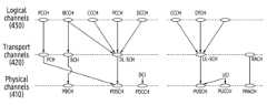
도 4는 통신 규격에서 채널들(channels)의 예를 도시한다. 상기 채널들은 통신 규격에서 정의되는 계층들에 따라, 물리 채널(physical channel)(410), 전송 채널(transport channel)(420), 및 논리 채널(logical channel)(430)을 포함할 수 있다.Figure 4 shows examples of channels in a communication standard. The channels may include a
도 4를 참고하면, 물리 채널(410)은 물리 계층에서 물리 신호들(physical signal)을 생성하기 위해 필요한 기능들(예: 채널코딩, HARQ 프로세싱, 변조, 다중 안테나 프로세싱, 자원 매핑)을 제공할 수 있다. 물리 계층에서, 물리 신호들은 OFDM 방식으로 변조되며, 시간-주파수 자원(예: 도 3의 자원 그리드의 자원)을 통해 무선 환경에서 전송될 수 있다.Referring to FIG. 4, the
하향링크 전송에서 물리 채널(410)은 PBCH(physical broadcast channel), PDSCH(physical downlink shared channel), 또는 PDCCH(physical downlink control channel) 중 적어도 하나를 포함할 수 있다. PDCCH는 DCI(downlink control information)를 운반하기 위해 이용될 수 있다. 일반적으로 하향링크 데이터는 PDSCH를 통해 전송되는 심볼들을 지칭하고, 하향링크 제어 신호는 PDCCH를 통해 전송되는 심볼들을 의미할 수 있다. 또한, 하향링크에서, 도 4에 도시된 채널들 외에, 동기화를 위해 동기 신호(예: PSS(primary synchronization signal), SSS(secondary synchronization signal)와 방송 신호(예: PBCH)를 포함하는 SS/PBCH 블록이 전송될 수 있다. 또한, 하향링크에서, 측정(measurement) 혹은 채널 정보를 획득하기 위한 CSI-RS(channel state information-reference signal), 채널 추정 및 복조를 위한 DMRS(demodulation reference signal), 및 PTRS(phase tracking reference signal)이 하향링크에서 전송될 수 있다.In downlink transmission, the
상향링크 전송에서 물리 채널(410)은 PUSCH(physical uplink shared channel), PUCCH(physical uplink control channel), 또는 PRACH(physical random access channel) 중 적어도 하나를 포함할 수 있다. PUSCH 또는 PUCCH는 UCI(uplink control information)을 운반하기 위해 이용될 수 있다. 일반적으로 상향링크 데이터는 PUSCH를 통해 전송되는 심볼들을 지칭하고, 상향링크 제어 신호는 UCI에 대응하는 심볼들을 의미할 수 있다. 예를 들어, UCI는 SR(scheduling request), HARQ(hybrid automatic request)-ACK(acknowledge) 비트(들), 또는 CSI(channel state information) 중 적어도 하나를 포함할 수 있다. 또한, 상향링크에서, 도 4에 도시된 채널들 외에, 채널 추정을 위해, 채널 추정 및 복조를 위한 DMRS 및 PTRS가 하향링크에서 전송될 수 있다.In uplink transmission, the
전송 채널(420)은, 물리 계층과 상기 물리 계층의 상위 레벨에 위치한 MAC(medium access channel) 계층을 연결하며, 무선 인터페이스를 통해 데이터가 어떻게 전송되는지에 따라 구분될 수 있다. 하향링크에서 전송 채널(420)은, 페이징을 위한 PCH(paging channel), 시스템 정보의 방송을 위한 BCH(broadcast channel), 또는 하향링크 데이터의 전송을 위한 DL-SCH(downlink shared channel) 중 적어도 하나를 포함할 수 있다. 상향링크에서 전송 채널(420)은, 랜덤 액세스 프리앰블의 전송을 위한 RACH(random access channel) 또는 하향링크 데이터의 전송을 위한 UL-SCH(uplink shared channel) 중 적어도 하나를 포함할 수 있다.The
논리 채널(430)은 전송 채널의 상위에 있으며, 전송 채널(420)에 맵핑된다. 논리 채널(430)은 제어 영역 정보의 전달을 위한 제어 채널과 사용자 영역 정보의 전달을 위한 트래픽 채널로 구분될 수 있다. 논리 채널(430)의 제어 채널은 PCCH(paging control channel), BCCH(broadcast control channel), CCCH(common control channel), 또는 DCCH(dedicated control channel) 중 적어도 하나를 포함할 수 있다. 논리 채널(430)의 트래픽 채널은 DTCH(dedicated traffic channel)을 포함할 수 있다.The
본 개시의 실시예들을 설명함에 있어, '데이터'는 기준 신호(reference signal)가 아닌 시퀀스들을 의미할 수 있다. 일 예로, 상향링크 통신에서 수신기에 의해 획득되는'데이터'는 PUSCH를 통해 전달되는 신호들을 의미할 수 있다. 그러나, PUSCH는 예시적인 것이며, 채널 추정(channel estimation)을 필요로 하는 다른 채널들(예: PDSCH, PBCH, PDCCH, PUCCH)에도 본 개시의 실시예들이 적용돌 수 있음은 물론이다.In describing embodiments of the present disclosure, 'data' may refer to sequences rather than a reference signal. For example, 'data' acquired by a receiver in uplink communication may refer to signals transmitted through PUSCH. However, PUSCH is an example, and of course, embodiments of the present disclosure can be applied to other channels that require channel estimation (e.g., PDSCH, PBCH, PDCCH, PUCCH).
MIMO(multiple-input multiple-output) 기술은 최근 크게 주목받는 분야로 활발한 연구가 진행되고 있다. 송신 안테나와 수신 안테나 사이의 채널이 독립적이고 송신 안테나들의 개수 및 수신 안테나들의 개수가 모두 M개로 동일하며, 대역폭과 전체 송신 전력이 고정된 상황을 가정하자. 이러한 상황에서, 평균 채널 용량은 단일 안테나에 비해 약 M배 증가한다. 예를 들어, MIMO 환경에서, 수신 방법은 MMSE(minimum mean-square error) 또는 MRC(maximum ratio combine)을 포함할 수 있다. 본 개시에서는 신호 수신 시 다른 셀의 간섭과 AWGN(adaptive white gaussian noise) 모두에 기반하여, 수신 방법(예: MMSE, MRC)의 성능을 향상시킬 수 있는 화이트닝 기법이 서술된다. 상술된 화이트닝 기법을 설명하기 위하여, LTE 통신 시스템 혹은 NR 통신 시스템에서의 상향링크 전송(예: PUSCH 전송)의 수신 상황이 예로 서술되나, 본 개시의 실시예들은 이에 한정되지 않는다. 다른 통신 시스템(예: IEEE 802.11 혹은 802.16e)에 따른 신호들을 수신하는 경우에도, 본 개시의 실시예들이 적용될 수 있다.MIMO (multiple-input multiple-output) technology is a field that has recently received a lot of attention, and active research is being conducted. Let us assume a situation where the channels between the transmit antenna and the receive antenna are independent, the number of transmit antennas and the number of receive antennas are the same (M), and the bandwidth and total transmit power are fixed. In this situation, the average channel capacity increases by approximately M times compared to a single antenna. For example, in a MIMO environment, the reception method may include minimum mean-square error (MMSE) or maximum ratio combine (MRC). In this disclosure, a whitening technique that can improve the performance of a reception method (e.g., MMSE, MRC) is described based on both interference from other cells and adaptive white gaussian noise (AWGN) when receiving signals. To explain the whitening technique described above, a reception situation of uplink transmission (eg, PUSCH transmission) in an LTE communication system or NR communication system is described as an example, but embodiments of the present disclosure are not limited thereto. Embodiments of the present disclosure can be applied even when receiving signals according to other communication systems (eg, IEEE 802.11 or 802.16e).
도 5는 슬롯 내에서 DMRS(demodulation reference signal)의 예를 도시한다. DMRS는 데이터를 복조하기 위해 이용되는 기준 신호(referenec signal, RS)이다. 데이터(예: PDSCH, PUSCH)를 복조하기 위해 채널을 추정하고, 채널 추정의 결과를 얻기 위하여, DMRS가 이용될 수 있다. 이하, 본 개시의 채널 추정과 채널 추정을 위한 DMRS를 이용한 동작들을 설명하기 위하여, NR 통신 시스템의 상향링크 전송이 예로 서술된다. 그러나, 본 개시의 실시예들이 NR 통신 시스템의 상향링크로 제한되는 것은 아니다. 하향링크 혹은 다른 통신 시스템에서도 본 개시의 실시예들이 적용될 수 있음은 물론이다.Figure 5 shows an example of a demodulation reference signal (DMRS) within a slot. DMRS is a reference signal (RS) used to demodulate data. DMRS can be used to estimate a channel to demodulate data (e.g., PDSCH, PUSCH) and obtain the result of channel estimation. Hereinafter, to explain channel estimation of the present disclosure and operations using DMRS for channel estimation, uplink transmission of the NR communication system is described as an example. However, embodiments of the present disclosure are not limited to the uplink of the NR communication system. Of course, embodiments of the present disclosure can be applied to downlink or other communication systems.
도 5를 참고하면, 기지국(예: 기지국(110))은 단말(예: 단말(120))로부터 신호를 수신할 수 있다. 단말(120)은 기지국(110)에게 상향링크 신호를 전송할 수 있다. 상기 수신된 신호는 상향링크 채널(예: PUSCH) 상에서 수신되는 데이터(이하, 수신 데이터)를 포함할 수 있다. 상기 수신 데이터는 시간 도메인(time domain)의 데이터 심볼들에서 전송될 수 있다. 또한, 상기 수신된 신호는 상기 데이터 심볼들의 채널 추정 및 코히어런트 복조(coherent demodulation)를 위한 기준 신호들(이하, 수신 기준 신호들)(예: DMRS)을 포함할 수 있다. 상기 수신 기준 신호들은 시간 도메인(time domain)의 DMRS 심볼들에서 전송될 수 있다. 기지국(110)은 단말(120)으로부터, 슬롯(slot)의 상기 데이터 심볼들에서 상기 수신 데이터를 수신하고 및 상기 DMRS 심볼들에서 상기 수신 기준 신호들을 수신할 수 있다. 슬롯은 14개의 심볼들(예: 심볼 #0(500), 심볼 #1(501), 심볼 #2(502), 심볼 #3(503), 심볼 #4(504), 심볼 #5(505), 심볼 #6(506), 심볼 #7(507), 심볼 #8(508). 심볼 #9(509), 심볼 #10(510), 심볼 #11(511), 심볼 #12(512), 및 심볼 #13(513))을 포함할 수 있다. 상기 14개의 심볼들 중에서 적어도 일부 심볼은 DMRS 시퀀스들을 운반하기 위해 이용될 수 있다. 예를 들어, 심볼 #2(502)의 구간 및 심볼 #11(511)의 구간은 DMRS 심볼들을 포함할 수 있다.Referring to FIG. 5, a base station (e.g., base station 110) may receive a signal from a terminal (e.g., terminal 120). The terminal 120 may transmit an uplink signal to the
기지국(110)은 수신 기준 신호들을 통해 기지국(110)과 단말(120) 간 채널을 추정할 수 있다. 기지국(110)은, 상기 수신 기준 신호들이 겪는 채널에 대한 정보를 획득할 수 있다. 예를 들어, 기지국(110)은, 상기 수신 기준 신호들의 DMRS 심볼들이 맵핑되는 위치와 상기 수신 데이터의 데이터 심볼들이 맵핑되는 위치들 간의 관계를 통해, 상기 수신 데이터가 겪은 채널에 대한 정보를 획득할 수 있다. 일 예로, 기지국(110)은 상기 수신 기준 신호들이 겪는 채널에 대한 정보를 기초로, 주파수 도메인에서의 보간(interpolation)이나 시간 도메인에서의 보간을 수행함으로써, 상기 수신 데이터가 겪은 채널에 대한 정보를 획득할 수 있다. 그러나, 전송 단위인 하나의 슬롯 내에서 데이터 심볼들의 개수는 일반적으로 DMRS 심볼들의 개수보다 많기 때문에, 데이터 심볼들 각각이 겪는 채널을 추정하는 동작은 많은 연산량을 요구할 수 있다. 뿐만 아니라, DMRS 심볼들 자체에 대한 연산이나 셀 간 간섭을 반영하지 못하므로, 수신 성능이 보장되지 않을 수 있다. 이를 위해, 수신단인 기지국(110)은 다양한 수신 기법들을 활용할 수 있다.The
복수의 수신 안테나들을 통해 수신된 수신 신호들에게 신호 결합 기법이 적용됨으로써 데이터 신호에 대한 추정 신호가 획득될 수 있다. 예를 들어, 상기 신호 결합 기법은 최대비 결합(maximal ratio combining, MRC), 선택 결합(selective combining), 또는 동일 이득 결합(equal gain combining)을 포함할 수 있다. MRC 기법은 각각의 데이터에 가중치를 주어 결합하는 방식이다. 선택 결합 기법은 데이터를 선택적 결합하는 방식이고, 동일 이득 결합 기법은 각각의 데이터에 동일한 가중치를 주고 평균값을 통해 결합하는 방식이다.An estimated signal for a data signal can be obtained by applying a signal combining technique to received signals received through a plurality of receiving antennas. For example, the signal combining technique may include maximal ratio combining (MRC), selective combining, or equal gain combining. The MRC technique is a method of combining each data by giving it a weight. The selective combining technique is a method of selectively combining data, and the equal gain combining technique is a method of giving equal weight to each data and combining them through the average value.
MRC 기법은 다중 안테나를 이용한 시스템에서 다중 경로로 수신되는 신호의 다이버시티(diversity)를 이용한 수신 기법의 하나로 SINR(signal to interference plus noise ratio)이 높은 잡음 제한적(noise-limited) 환경에서 최적의 성능을 보이는 것으로 알려져 있다. 그런데, MRC 기법을 사용하여 구한 추정 신호는 인접 셀의 간섭 신호의 영향을 고려하지 않은 것이다. 또한, 실제 다중 셀 환경에서 셀 경계에 위치하는 단말은 인접 셀의 영향을 받게 되어 낮은 SINR을 가지게 된다. 따라서, 다중 셀 환경에서 셀 경계에 위치한 단말은 MRC 기법을 사용하여 최적의 성능을 얻을 수 없을 수 있다. 셀룰러 시스템(예: 3GPP(3rd generation partnership project)의 LTE(long term evolution) 통신 시스템 혹은 NR(new radio) 통신 시스템)에서는 AWGN뿐만 아니라 다른 셀로부터의 간섭도 존재할 수 있다. 잡음 성분은 AWGN과 다른 셀로부터 오는 간섭을 포함할 수 있다. 상기 간섭이 존재하는 환경에서는, 화이트닝을 이용한 MRC 수신기의 성능이 일반 MRC 수신기의 성능보다 우수하다. 반대로, 간섭이 존재하지 않는 환경에서는, 화이트닝을 이용한 MRC 수신기의 성능이 일반 MRC 수신기의 성능과 동일하다. 다만, 구현상의 이유로 화이트닝을 이용한 MRC 수신기의 성능은 일반 MRC 수신기의 성능보다 열화될 수 있다. 이하, 화이트닝을 이용한 MRC 수신기는, MMES 방식과 같이, 신호를 수신하기 위하여, MRC 수신기에 화이트닝 행렬의 적용 블록이 부가된 구조를 가질 수 있다.The MRC technique is one of the reception techniques that utilizes the diversity of signals received through multiple paths in a system using multiple antennas, and provides optimal performance in a noise-limited environment with a high SINR (signal to interference plus noise ratio). It is known to show . However, the estimated signal obtained using the MRC technique does not take into account the influence of interference signals from adjacent cells. Additionally, in a real multi-cell environment, a terminal located at a cell border is affected by neighboring cells and has a low SINR. Therefore, in a multi-cell environment, a terminal located at a cell border may not be able to achieve optimal performance using the MRC technique. In a cellular system (e.g., a long term evolution (LTE) communication system or a new radio (NR) communication system of the 3rd generation partnership project (3GPP)), interference from other cells as well as AWGN may exist. Noise components may include interference from AWGN and other cells. In an environment where the above interference exists, the performance of an MRC receiver using whitening is superior to that of a general MRC receiver. Conversely, in an environment where interference does not exist, the performance of an MRC receiver using whitening is the same as that of a general MRC receiver. However, for implementation reasons, the performance of an MRC receiver using whitening may be worse than that of a general MRC receiver. Hereinafter, the MRC receiver using whitening may have a structure in which an application block of a whitening matrix is added to the MRC receiver in order to receive a signal, like the MMES method.
이하에서, 다중 송신 안테나를 갖는 방송 통신 시스템의 MMSE 수신에 관한 기술적 특징이 설명될 수 있다. 예를 들어, 다양한 패턴의 간섭 환경에서 수신 성능을 개선하기 위한 기술적 특징이 제안될 수 있다. 이하에서 설명되는 전자 장치는 기지국에 포함될 수 있다. 예를 들어, 전자 장치는 도 2의 DU(210)에 포함되거나, DU(210)의 기능 중 적어도 일부 또는 전부를 수행하는 장치일 수 있다.Below, technical features related to MMSE reception of a broadcast communication system with multiple transmission antennas can be described. For example, technical features may be proposed to improve reception performance in environments with various patterns of interference. Electronic devices described below may be included in a base station. For example, the electronic device may be included in the
본 개시는, 일부 통신 규격(예: 3GPP(3rd generation partnership project))에서 사용되는 용어들을 이용하여 실시 예들을 설명하지만, 이는 설명을 위한 예시일 뿐이다. 본 개시의 다양한 실시 예들은, 다른 통신 및 방송 시스템에서도, 용이하게 변형되어 적용될 수 있다.This disclosure describes embodiments using terms used in some communication standards (e.g., 3rd generation partnership project (3GPP)), but this is only an example for explanation. Various embodiments of the present disclosure can be easily modified and applied to other communication and broadcasting systems.
일 실시 예에 따르면, 간섭 환경에서 상향링크 데이터 채널(physical uplink shared channel, PUSCH) 신호 송신 시, 안테나의 개수가이고, 레이어의 개수가일 수 잇다. 이 경우, k 번째 서브캐리어에서 수신 신호는 하기의 수학식과 같이 표현될 수 있다.According to one embodiment, when transmitting an uplink data channel (physical uplink shared channel, PUSCH) signal in an interference environment, the number of antennas is and the number of layers is It can be. In this case, the received signal on the k-th subcarrier can be expressed as the following equation.
수학식 1을 참고하면,는 k 번째 서브캐리어(subcarrier)에서 크기의 수신 신호 벡터이다.는번째 서브캐리어에 해당하는 크기의 채널 행렬이다.는번째 서브캐리어에 해당하는 크기의 송신 신호 벡터이다.는 크기의 잡음 및 간섭 벡터이다.Referring to
인접한 다른 셀의 간섭이 존재하는 경우, 서비스되는 중인 장치(또는 사용자)의 PUSCH 수신 성능이 열화될 수 있다. 전자 장치(예: MMSE 수신기)는 하기의 수학식에 따라 등화(equalization)를 수행할 수 있다.If there is interference from another nearby cell, the PUSCH reception performance of the device (or user) being served may deteriorate. An electronic device (e.g., MMSE receiver) may perform equalization according to the equation below.
수학식 2를 참고하면, 는의 공액 복소수 전치를 의미한다.는 () 크기의 가중치(예: MMSE 가중치)이다.는 k번째 서브캐리어에 해당하는 () 크기의 전자 장치에서 추정된 채널 행렬이다.은 추정 크기의 추정된 잡음(noise) 및 간섭 성분의 공분산 행렬을 나타낸다. 이하에서,은 잡음 공분산 행렬으로 설명될 수 있다.Referring to
전자 장치(예: MMSE 수신기)에서 간섭에 의한 영향을 줄이기 위해서는 간섭 및 잡음의 공분산 행렬에 대한 정확도 높은 추정이 요구될 수 있다. 예를 들어, 채널 추정 오류(channel estimation error)로 발생되는을 보정하기 위해 하기의 수학식과 같은 다이아고널 로딩(diagonal loading) 기법이 사용될 수 있다.To reduce the impact of interference in electronic devices (e.g. MMSE receivers), the covariance matrix of interference and noise A highly accurate estimate may be required. For example, caused by channel estimation error To correct, a diagonal loading technique such as the equation below can be used.
수학식 3에서,은 잡음 공분산 행렬인이 보정된 값이다.은 하기의 수학식 4와 같이 표현될 수 있다.In
는 추정된 채널 행렬이며,는 최적화를 위한 파라미터이며,는 도플러 주파수이다.is the estimated channel matrix, is a parameter for optimization, is the Doppler frequency.
일 실시 예에 따르면, 전자 장치(예: MMSE 수신기)는 채널 추정기(channel estimator)를 통해 채널을 추정할 수 있다. 전자 장치(예: MMSE 수신기)는 채널 추정의 결과에 기반하여, 외란 추정기(disturbance estimator)를 통해을 측정(또는 획득)할 수 있다. 전자 장치(예: MMSE 수신기)는 adaptation unit 및 displacement unit을 통해 잡음 및 간섭 공분산 및 채널 추정의 결과에 기반하여,을 보정함으로써을 획득(또는 계산)할 수 있다.According to one embodiment, an electronic device (e.g., MMSE receiver) may estimate a channel through a channel estimator. Based on the results of the channel estimation, the electronic device (e.g. MMSE receiver) uses a disturbance estimator to can be measured (or obtained). The electronic device (e.g., MMSE receiver) based on the results of noise and interference covariance and channel estimation through adaptation unit and displacement unit, By correcting can be obtained (or calculated).
일 실시 예에 따르면, 잡음(noise) 성분 및 간섭(interference) 성분의 공분산 행렬인 잡음 공분산 행렬(noise covariance matrix)을 획득(또는 계산)하기 위해, 추정된 채널을 이용하여, 잡음 공분산 행렬을 개선하는 알고리즘이 사용될 수 있다. 다만, 상기 알고리즘에 따르면, 잡음 공분산 행렬을 식별(또는 획득, 계산)하기 위한 샘플들의 개수에 따른 잡음 공분산의 왜곡이 발생될 수 있다. 유한한 개수의 샘플들을 이용하여 잡음 공분산 행렬을 식별(또는 획득, 계산)할 때, 안테나들의 개수에 비해 샘플들의 개수가 충분하지 않은 경우, 잡음 공분산의 왜곡이 발생될 수 있다. 잡음 공분산의 왜곡은 MMSE 수신기의 간섭 성능 저하를 발생시킬 수 있다. 이하에서, 프리-화이트닝(pre-whitening) 구조 수신기에서 잡음 공분산의 왜곡이 발생되는 예 설명될 수 있다.According to one embodiment, the noise covariance matrix is improved using the estimated channel to obtain (or calculate) a noise covariance matrix, which is the covariance matrix of the noise component and the interference component. algorithms can be used. However, according to the above algorithm, distortion of the noise covariance may occur depending on the number of samples for identifying (or obtaining or calculating) the noise covariance matrix. When identifying (or obtaining or calculating) a noise covariance matrix using a finite number of samples, if the number of samples is insufficient compared to the number of antennas, distortion of the noise covariance may occur. Distortion of noise covariance can cause interference performance degradation of the MMSE receiver. Below, an example in which distortion of noise covariance occurs in a pre-whitening structure receiver can be explained.
예를 들어, 프리-화이트닝(pre-whitening) 구조 수신기에서 하기의 수학식에 따라 등화가 수행될 수 있다. 하기의 수학식은, 수학식 2의 행렬의 역 정리(matrix inversion lemma)에 따라 구성될 수 있다.For example, in a pre-whitening structure receiver, equalization may be performed according to the equation below. The following equation can be constructed according to the matrix inversion lemma of
수학식 5를 참고하면,이다.Referring to
수학식 5에 따르면, 잡음 공분산 행렬()의 역행렬 연산이 수행되어야 한다. 잡음 공분산을 획득(또는 계산)하기 위한 샘플들의 개수가 행렬의 차원(dimension)의 크기인 안테나들의 개수보다 적으면, 랭크 부족(rank deficient)이 발생될 수 있다. 랭크 부족이 발생된 경우, 잡음 공분산 행렬()의 역행렬을 획득(또는 계산)할 수 없어, 성능 저하가 발생될 수 있다. 이와 같은 성능 저하는 Massive MIMO 시스템과 같이 안테나 수가 많을수록 더 크게 발생하며, 단말(또는 사용자)에게 할당된 RB들의 개수가 적어서, 잡음 공분산 행렬의 획득(또는 계산)에 사용되는 샘플의 수가 적을수록 성능 저하가 크게 발생할 수 있다.According to
또한, 잡음 공분산 행렬()을 획득(또는 계산)하기 위해, 주파수 축에서 고정된 개수의 샘플들이 사용될 수 있다. 간섭이 없거나 간섭의 통계적인 특징이 주파수 축에서 변화가 없는 경우, 최대한 많은 RE들이 획득(또는 계산)에 사용되는 경우보다 고정된 개수의 샘플들이 이용되는 경우,의 추정 오차가 증가될 수 있다.의 추정 오차가 증가됨에 따라 전자 장치(예: MMSE 수신기)의 성능이 감소될 수 있다. 이와 반대로, 일부 RB들에 만 간섭이 존재하거나, 간섭이 RB 단위로 변화가 크게 발생되는 경우에도, 추정 오차가 증가하여 전자 장치(예: MMSE 수신기)의 성능이 감소될 수 있다.Additionally, the noise covariance matrix ( ), a fixed number of samples on the frequency axis can be used. If there is no interference or the statistical characteristics of the interference do not change in the frequency axis, as many REs as possible When a fixed number of samples are used for acquisition (or calculation), The estimation error may increase. As the estimation error of increases, the performance of the electronic device (e.g., MMSE receiver) may decrease. Conversely, even when interference exists only in some RBs or when interference occurs significantly on a RB-by-RB basis, As the estimation error increases, the performance of the electronic device (e.g., MMSE receiver) may be reduced.
이하 명세서는, 추정 오차의 증가에 따른 전자 장치(예: MMSE 수신기) 성능의 감소를 보완하기 위해, 다양한 간섭 패턴 환경에서 간섭 및 잡음의 영향을 최소화하기 위한 장치 및 방법이 제안될 수 있다. 구체적으로, 전자 장치(예: MMSE 수신기)는 간섭 및 잡음의 패턴을 식별(또는 감지)하고, 식별된 패턴에 기반하여, 잡음 공분산 행렬을 추정할 수 있다. 전자 장치(예: MMSE 수신기)는 잡음 공분산 행렬의 추정 오차를 최소화하도록, 잡음 공분산 행렬을 재구성할 수 있다.The following specifications are: To compensate for the decrease in performance of electronic devices (e.g., MMSE receivers) due to an increase in estimation error, devices and methods for minimizing the effects of interference and noise in various interference pattern environments may be proposed. Specifically, an electronic device (e.g., MMSE receiver) may identify (or detect) patterns of interference and noise, and estimate a noise covariance matrix based on the identified patterns. An electronic device (e.g., MMSE receiver) may reconstruct the noise covariance matrix to minimize the estimation error of the noise covariance matrix.
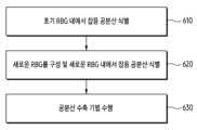
도 6은 잡음 공분산 행렬의 추정 오차를 보정하기 위한 전자 장치의 동작에 관한 흐름도를 도시한다. 동작 610 내지 동작 630은 전자 장치(또는 수신기)(예: 전자 장치의 프로세서)에서 수행될 수 있다.FIG. 6 shows a flowchart of an operation of an electronic device to correct an estimation error of a noise covariance matrix.
도 6을 참고하면, 동작 610 내지 동작 630에서, 전자 장치는 추정된 채널 및 수신된 신호에 기반하여, 정확한 잡음 공분산을 획득할 수 있도록 샘플 영역을 설정할 수 있다. 전자 장치는 설정된 샘플 영역 내에서 잡음 공분산을 획득(또는 계산)할 수 있다. 전자 장치는 샘플들의 개수에 따라 발생되는 잡음 공분산의 추정 오차를 보정할 수 있다. 동작 610 내지 동작 630의 구체적인 동작이 이하에서 설명될 것이다.Referring to FIG. 6, in
동작 610에서, 전자 장치는 미리 지정된 개수로 고정된 RB들에 대응하는 RE(resource element)들을 샘플로 설정할 수 있다. 전자 장치는 설정된 샘플에 기반하여, 잡음 공분산을 획득(또는 계산)할 수 있다. 동작 630의 구체적인 동작은 도 7에서 후술될 것이다.In
동작 620에서, 전자 장치는 새로운 RBG(resource block group)를 구성하고, 새로운 RBG 내에서 잡음 공분산을 식별(또는 획득)할 수 있다. 전자 장치는 동작 610에서 설정된 RBG들이 아닌 새로운 RBG를 구성할 수 있다. 전자 장치는 새로운 RBG 내에서 잡음 공분산을 식별(또는 획득)할 수 있다. 동작 620의 구체적인 동작은 도 8에서 후술될 것이다.In
동작 630에서, 전자 장치는 공분산 수축(covariance shrinkage) 기법을 수행할 수 있다. 예를 들어, 전자 장치는 하나의 RBG 내의 샘플의 개수(예: 하나의 RBG 내의 샘플의 개수)가 임계 개수 미만임을 식별하는 것에 기반하여, 공분산 수축 기법을 수행할 수 있다. 동작 630의 구체적인 동작은 도 9에서 후술될 것이다.In
도 7은 RBG 영역 내에서 잡음 공분산을 획득하기 위한 전자 장치의 동작에 관한 흐름도를 도시한다. 도 7의 동작 710 및 동작 720은 도 6의 동작 610과 관련될 수 있다.Figure 7 shows a flowchart of the operation of an electronic device to obtain noise covariance within the RBG area.
동작 710에서, 전자 장치는 수신 신호, 추정된 채널, 및 기준 신호에 기반하여 잡음 및 간섭을 추정할 수 있다. 예를 들어, 전자 장치는 설정된 샘플들에 따른 수신 신호, 추정된 채널, 및 기준 신호에 기반하여, 잡음 및 간섭을 추정할 수 있다.In
동작 720에서, 전자 장치는 초기 RBG(resource block group) 당 잡음 공분산을 획득할 수 있다. 예를 들어, 전자 장치는 수신 신호, 추정된 채널, 및 기준 신호에 기반하여 추정된 잡음 및 간섭에 기반하여, 초기 RBG 당 잡음 공분산을 획득할 수 있다.In
일 실시 예에 따르면, 초기 설정된 샘플에 사용된 RBG의 집합이로 표시될 수 있다. 각각의 RBG는 연속된 RB 내에서 지정된 개수의 RB들을 포함할 수 있다. 예를 들어, 각각의 RBG는 지정된 개수의 연속된 RB들을 포함할 수 있다.According to one embodiment, the set of RBGs used in the initially set sample is It can be displayed as . Each RBG may include a specified number of RBs within a contiguous RB. For example, each RBG may include a specified number of consecutive RBs.
예를 들어, 연속한 10 개의 RB들이 할당된 경우,의 크기가 2 RBs로 설정될 수 있다. 이 경우,로 설정되고,는 하기의 표 3과 같이 설정될 수 있다.For example, if 10 consecutive RBs are allocated, The size of can be set to 2 RBs. in this case, is set to, Can be set as shown in Table 3 below.
표 3과 같이 가 설정된 경우, 전자 장치는 잡음 공분산을 획득(또는 계산)하기 위해, 잡음 벡터를 식별할 수 있다.번째 서브캐리어, 번째 DMRS 심볼에 해당하는 수신 신호를 통해 추정된 잡음 벡터는 하기의 수학식과 같이 구성될 수 있다.As shown in Table 3 If is set, the electronic device can identify the noise vector to obtain (or calculate) the noise covariance. second subcarrier, The noise vector estimated through the received signal corresponding to the th DMRS symbol can be configured as in the following equation.
수학식 6을 참고하면,는번째 서브캐리어 및번째 DMRS 심볼에 해당하는 수신 신호이다.는번째 서브캐리어 및번째 DMRS 심볼에서 추정된 채널이다.는 DMRS 패턴에 따른 송신 신호이다.는번째 DMRS 심볼에서번째 위치한 RE에서 추정된 잡음 벡터이다.Referring to
획득(또는 측정)된 잡음 벡터(또는 잡음 및 간섭 벡터)에 기반하여, 영역에서 잡음 공분산이 하기의 수학식과 같이 획득(또는 계산)될 수 있다.Based on the acquired (or measured) noise vector (or noise and interference vector), The noise covariance in the domain can be obtained (or calculated) as shown in the equation below.
수학식 7을 참고하면, Nsamp는 RBG 내의 샘플들의 개수이다. 예를 들어, 하나의 RB에서 샘플의 개수는 RB 내의 서브캐리어의 개수와 DMRS 심볼의 개수의 곱일 수 있다. 따라서, RBG 내의 샘플들의 개수는 RBG 내에 포함된 RB의 개수와 하나의 RB에서의 샘플의 개수의 곱일 수 있다.는 영역에서 잡음 공분산이다.Referring to
도 8은 새로운 RBG를 설정하기 위한 알고리즘을 도시한다. 도 8의 단계들은 도 6의 동작 620과 관련될 수 있다.Figure 8 shows an algorithm for setting a new RBG. The steps in FIG. 8 may be related to
도 8을 참고하면, 도 7에서 획득된 및 간섭 패턴에 기반하여, 새로운 RBG를 구성하고 및 새로운 RBG에서의 잡음 공분산을 획득할 수 있다. 새로운 RBG는로 표현될 수 있다. 새로운 RBG에서의 잡음 공분산은로 표현될 수 있다. 예를 들어, 새로운 영역을 구하기 위한 판단 기준인가 설정될 수 있다.는 하기의 수학식과 같이 설정될 수 있다.Referring to Figure 8, obtained in Figure 7 And based on the interference pattern, a new RBG can be configured and noise covariance in the new RBG can be obtained. The new RBG is It can be expressed as The noise covariance in the new RBG is It can be expressed as For example, new Judgment criteria for finding the area can be set. Can be set as in the following equation.
수학식 8을 참고하면, F(A, B)는 행렬 A 및 행렬 B의 원소들에 기반하여 스칼라 값을 출력하는 함수이다. 따라서,는 행렬 및 행렬의 원소들에 기반하여 출력된 스칼라 값일 수 있다. 예를 들어, F(a,b)에 따라는 하기의 수학식들과 같이 구성될 수 있다.Referring to
수학식 10을 참고하면, tr(A)는 행렬 A의 대각합(trace) 함수이다.Referring to
상술한 수학식 9 및 수학식 10에 따라, 잡음 공분산 행렬 전체 또는 잡음 공분산 행렬의 대각 성분에 기반하여 RBG간의 간섭 특성의 변화가 식별(또는 감지) 될 수 있다.According to
는 각 RBG 마다 식별(또는 계산)될 수 있다. 전자 장치는의 index에 따른 변화가 적은 RB들의 세트인 영역을 식별할 수 있다.는 이웃한 및에 따라 획득된가 하기의 수학식을 만족하는 모든 이웃한가 합쳐지는 것으로 식별될 수 있다.Can be identified (or calculated) for each RBG. electronic devices index of A set of RBs with little change depending on Areas can be identified. is neighboring and obtained according to All neighbors that satisfy the equation below can be identified as being combined.
수학식 11을 참고하면, Th1은 시스템 최적화 파라미터이다. Th1은 미리 지정되거나, 상황에 따라 변경될 수 있다.Referring to Equation 11, Th1 is a system optimization parameter. Th1 may be designated in advance or changed depending on the situation.
전자 장치는가 하기의 수학식을 만족하는 모든 이웃한를 합쳐(combine)를 식별(또는 계산)할 수 있다.electronic devices All neighbors that satisfy the equation below combine can be identified (or calculated).
상술한 실시 예에 따라, 전자 장치는, 도 8에 도시된 단계 810 내지 단계 870에 따른 알고리즘에 기반하여,를 식별할 수 있다. 단계 810 내지 단계 870에 따른 알고리즘에서,는 초기에 설정된 RBG들의 개수이고,는 새롭게 설정된 RBG들의 개수일 수 있다.According to the above-described embodiment, the electronic device, based on the algorithm according to
도 9는 공분산 수축 기법을 수행하기 위한 전자 장치의 동작에 관한 흐름도를 도시한다. 동작 910 내지 동작 980은 전자 장치(또는 수신기)(예: 전자 장치의 프로세서)에서 수행될 수 있다. 동작 910 내지 동작 980은 도 6의 동작 630과 관련될 수 있다.9 shows a flow diagram of the operation of an electronic device to perform a covariance shrinkage technique.
도 9를 참고하면, 동작 910에서, 전자 장치는 RBG 내의 샘플들의 개수를 식별할 수 있다. 예를 들어,은 샘플들의 개수가 무한하지 않기 때문에, 추정된 잡음 공분산은, 이상적인 잡음 공분산에 비해 추정 오차가 발생할 수 있다. 따라서, 행렬의 차원의 크기에 비해 충분하지 않은 샘플들의 개수에 의해 발생되는 추정 오차를 감소시키기 위해, 공분산 수축 기법이 적용될 수 있다.Referring to FIG. 9, in
동작 920에서, 전자 장치는 공분산 수축 기법의 수행이 필요한지 여부를 식별할 수 있다. 예를 들어, 전자 장치는 샘플들의 개수가 하기의 수학식 12를 만족하는 RBG(l)에 대해서만 공분산 수축 기법을 적용할 수 있다. 수학식 12를 만족하지 않는 경우는 샘플들의 개수가 충분함을 의미할 수 있다. 수학식 12를 만족하지 않는, 샘플들의 개수가 충분한 RGB 내에서는 공분산 수축 기법이 수행되지 않을 수 있다. 이에 따라, 불필요한 연산 복잡도가 최소화될 수 있다.At
수학식 12를 참고하면, G(Nrx)는 시스템에 따라 변경될 수 있다. 예를 들어, G(Nrx)는 수학식 13과 같이 설정될 수 있다.Referring to
수학식 13을 참고하면, k는 시스템에 따라 변경될 수 있다.Referring to
이하에서는, 잡음 공분산 행렬에 공분산 수축 기법이 적용되는 동작인, 동작 941, 동작 942, 동작 951, 및 동작 952가 설명될 수 있다. 동작 941, 동작 942, 동작 951, 및 동작 952를 참고하면, 하기의 수학식 14에 따라에 공분산 수축(또는 선형 수축) 기법이 적용될 수 있다.Hereinafter,
수학식 14를 참고하면,는가 공분산 수축 기법에 따라 보정된 행렬이다.는 공분산 수축 계수이다.는 낮은 복잡도로 결정될 수 있다. 예를 들어,는 RBLW(Rao-Blackwell Ledoit-Wolf) 기법 또는 OAS(oracle approximate shrinkage) 기법에 기반하여, 결정될 수 있다.는 크기의 타겟 행렬이다.Referring to Equation 14, Is This is a matrix corrected according to the machining covariance shrinkage technique. is the covariance shrinkage coefficient. can be determined with low complexity. for example, Can be determined based on the Rao-Blackwell Ledoit-Wolf (RBLW) technique or the oracle approximate shrinkage (OAS) technique. Is is the target matrix of size.
예를 들어, 잡음 공분산에 단위 행렬(identity matrix)이 더해지는 형태와 달리, 실제 안테나 별로 전력이 다른 경우를 고려하여, 안테나의 전력 차분의 정도에 따라 타겟 행렬()이 결정될 수 있다. 타겟 행렬은 하기의 수학식 15와 같이 구성될 수 있다.For example, unlike the form in which an identity matrix is added to the noise covariance, considering the case where the actual power is different for each antenna, the target matrix ( ) can be determined. The target matrix can be configured as shown in
수학식 15를 참고하면,는의 잡음 및 간섭 분산의 번째 대각 성분(diagonal element)이다.의 행렬의 대각 성분(diagonal element)은의 대각선 원소와 같도록 구성될 수 있다.의 행렬의 비대각 성분(off-diagonal element)는 모두 0으로 구성될 수 있다.는 크기의 단위 행렬(identity matrix)이다. Th3는 안테나들의 전력 차분에 관한 임계 값이다. 상술한 동작에 기반하여, 타겟 행렬()이 결정되고, 공분산 수축이 수행될 수 있다. (동작 951 및 동작 952)Referring to
예를 들어,의 비대각 성분은 0이기 때문에,의 값이 1이면(),는로 설정될 수 있다. 따라서,의 비대각 성분이 0일 수 있다. 대각 행렬의 역함수가 대각 행렬이므로, 프리-화이트닝 연산이 수행되는 경우, 하기의 수학식 16과 같이 복잡도가 감소될 수 있다. (동작 980)for example, Since the off-diagonal component of is 0, If the value of is 1 ( ), Is It can be set to . thus, The off-diagonal component of may be 0. Since the inverse function of a diagonal matrix is a diagonal matrix, when a pre-whitening operation is performed, complexity can be reduced as shown in Equation 16 below. (action 980)
일 실시 예에 따르면, CoMP(cooperative multiple point) 수신과 같이 물리적으로 안테나들이 떨어져 있거나, 모뎀에 입력되는 안테나들이 다른 빔포밍(beamforming) 또는 안테나 편파(antenna polarization)에 의해 구분되는 경우, 안테나 집합들 간에 상관관계(correlation)가 적을 수 있다. 이 경우,의 비대각 성분이 0으로 근사될 수 있다.According to one embodiment, when the antennas are physically separated, such as during cooperative multiple point (CoMP) reception, or when the antennas input to the modem are distinguished by different beamforming or antenna polarization, antenna sets There may be little correlation between the two. in this case, The off-diagonal component of can be approximated as 0.
예를 들어, 모든 안테나들에 대한 잡음 공분산이 하기의 수학식 17을 만족하는 경우, 잡음 공분산 행렬은 수학식 20과 같은 개의 서브블록들(subblocks)을 갖는 블록 대각 행렬 형태로 근사화될 수 있다.For example, if the noise covariance for all antennas satisfies Equation 17 below, the noise covariance matrix is Equation 20: It can be approximated in the form of a block diagonal matrix with subblocks.
수학식 17을 참고하면,은 수학식 18과 같이 구성된다.는 수학식 19와 같이 구성된다.Referring to Equation 17, is composed as shown in Equation 18. is composed as shown in Equation 19.
수학식 20을 참고하면,는에 해당하는 크기의 수신되는 잡음 공분산이다. 블록 대각 행렬 형태로이 근사되는 경우,인와의 특성이 다르기 때문에, 수학식 21과 같이 각각에 공분산 수축 기법이 적용될 수 있다. 각각에 공분산 수축 기법이 적용됨에 따라, 전자 장치의 간섭 성능이 증가하고, 연산 복잡도가 감소될 수 있다. (동작 941 및 동작 942)Referring to
수학식 21을 참고하면,는 수학식 22와 같이 설정될 수 있다.Referring to Equation 21, Can be set as in Equation 22.
수학식 22를 참고하면,는 행렬이다.Referring to Equation 22, Is It is a procession.
상술한 동작들에 따라, 공분산 수축 기법이 적용된 잡음 공분산 행렬의 역함수를 통해, 프리-화이트닝 연산이 수행될 수 있다. 달리 표현하면, 공분산 수축 계수()가 1이 아닌 경우, 공분산 수축 기법에 따라 대각 행렬로 보정(또는 구성)되지 않은 잡음 공분산 행렬의 역함수를 통해, 프리-화이트닝 연산이 수행될 수 있다. (동작 970) 공분산 수축 계수()가 1인 경우, 공분산 수축 기법에 따라 대각 행렬로 보정(또는 구성)된 잡음 공분산 행렬의 역함수를 통해, 프리-화이트닝 연산이 수행될 수 있다. (동작 980)According to the above-described operations, a pre-whitening operation can be performed through the inverse function of the noise covariance matrix to which the covariance contraction technique is applied. In other words, the covariance shrinkage coefficient ( ) is not 1, a pre-whitening operation can be performed through the inverse function of the noise covariance matrix that has not been corrected (or configured) as a diagonal matrix according to the covariance shrinkage technique. (Operation 970) Covariance shrinkage coefficient ( ) is 1, a pre-whitening operation can be performed through the inverse function of the noise covariance matrix corrected (or configured) as a diagonal matrix according to the covariance shrinkage technique. (action 980)
일 실시 예에 따르면, 전자 장치는 다양한 간섭 패턴에 대해 정확도 높은 잡음 공분산을 식별하기 위해, 적절한 샘플 영역을 결정(또는 도출)하고, 결정된(또는 도출된) 샘플 영역 내의 샘플들의 개수가 부족한 경우, 잡음 공분산에 공분산 수축 기법을 적용할 수 있다. 전자 장치는 잡음 공분산에 공분산 수축 기법을 적용함으로써, 잡음 공분산의 추정 오차를 감소시킬 수 있다. 결과적으로 잡음 및 간섭 분산의 오차가 감소되어 간섭 환경에서의 MMSE 수신 성능이 향상될 수 있다. 이하에서는, 상술한 실시 예에 따른 구체적인 전자 장치의 동작의 예가 설명될 수 있다. 서브-밴드 간섭 환경에서의 전자 장치의 동작 및 전자 장치의 동작에 따른 효과가 도 10a 및 도 10b를 통해 설명될 수 있다. 풀-밴드 간섭 환경에서 전자 장치의 동작 및 전자 장치의 동작에 따른 효과가 도 11a 및 도 11b를 통해 설명될 수 있다.According to one embodiment, the electronic device determines (or derives) an appropriate sample area to identify noise covariance with high accuracy for various interference patterns, and when the number of samples in the determined (or derived) sample area is insufficient, Covariance shrinkage techniques can be applied to noise covariance. An electronic device can reduce the estimation error of noise covariance by applying a covariance contraction technique to the noise covariance. As a result, errors in noise and interference distribution can be reduced, improving MMSE reception performance in an interference environment. Below, examples of specific operations of electronic devices according to the above-described embodiments may be described. The operation of an electronic device in a sub-band interference environment and the effects of the operation of the electronic device can be explained through FIGS. 10A and 10B. The operation of an electronic device and the effects of the operation of the electronic device in a full-band interference environment can be explained through FIGS. 11A and 11B.
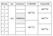
도 10a는 서브-밴드(sub-band) 간섭 환경에서 새로운 RBG가 구성되는 예를 도시한다.Figure 10a shows an example of a new RBG being configured in a sub-band interference environment.
도 10b는 서브-밴드(sub-band) 간섭 환경에서 초기 RBG 및 새로운 RBG에 관한 MSE 성능을 나타내는 그래프들의 예를 도시한다.Figure 10b shows examples of graphs showing MSE performance for an initial RBG and a new RBG in a sub-band interference environment.
도 10a를 참고하면, 도 10a는 간섭이 서브-밴드로 존재하는 환경에서 RBG 영역을 도시한다. 예를 들어, 사용자인 UE 0에게 RB 인덱스 0 내지 7의 RB들이 할당될 수 있다. 할당된 RB들 중 RB 인덱스 2 내지 4의 RB들에 간섭이 존재할 수 있다.Referring to FIG. 10A, FIG. 10A shows the RBG area in an environment where interference exists in sub-bands. For example, RBs with
Fix RBG는 고정된 RB 크기가 4 RBs로 설정된 초기 RBG(예:)를 의미할 수 있다. Proposed RBG는 Fix RBG에서 식별된 잡음 공분산에 기반하여, 새롭게 설정된 RBG(예:)를 의미할 수 있다. 도 6의 동작 620에 기반하여, Proposed RBG가 구성될 수 있다. Proposed RBG는 3 개의 RBG들(예: 내지)로 구성될 수 있다. 전자 장치는 Proposed RBG에 따라 구분된 복수의 RB들 상에서 신호를 수신할 수 있다. Proposed RBG에 기반하여, 잡음 공분산 행렬이 획득될 수 있다. 획득된 잡음 공분산 행렬에 공분산 수축 기법이 적용될 수 있다.Fix RBG is an initial RBG with a fixed RB size set to 4 RBs, e.g. ) can mean. Proposed RBG is based on the noise covariance identified in Fix RBG and is used to create a newly established RBG, e.g. ) can mean. Based on
도 10b를 참고하면, 그래프(1001)는 Fix RBG에서, SNR에 따른 송신 신호 및 MMSE 수신 신호의 MMSE를 나타낸다. 그래프(1002)는 Proposed RBG에서, SNR에 따른 송신 신호 및 MMSE 수신 신호의 MMSE를 나타낸다. 따라서, 상술한 실시 예가 적용되는 경우, 1 내지 2 dB의 성능 이득 효과가 있다.Referring to FIG. 10B, a
도 11a는 풀-밴드(full-band) 간섭 환경에서 새로운 RBG가 구성되는 예를 도시한다.Figure 11a shows an example of a new RBG being configured in a full-band interference environment.
도 11b는 풀-밴드(full-band) 간섭 환경에서 초기 RBG 및 새로운 RBG에 관한 MSE 성능을 나타내는 그래프들의 예를 도시한다.Figure 11b shows examples of graphs representing MSE performance for an initial RBG and a new RBG in a full-band interference environment.
도 11a를 참고하면, 도 11a는 간섭이 풀-밴드로 존재하는 환경에서 RBG 영역을 도시한다. 예를 들어, 사용자인 UE 0에게 RB 인덱스 0 내지 39의 RB들이 할당될 수 있다. 할당된 RB들 전체에 간섭이 존재할 수 있다. 예를 들어, 할당된 RB들 전체의 간섭의 통계적 특성이 같을 수 있다.Referring to FIG. 11A, FIG. 11A shows the RBG area in an environment where interference exists in full-band. For example, RBs with
Fix RBG는 고정된 RB 크기가 4 RBs로 설정된 초기 RBG(예:)를 의미할 수 있다. Proposed RBG는 Fix RBG에서 식별된 잡음 공분산에 기반하여, 새롭게 설정된 RBG(예:)를 의미할 수 있다. 도 6의 동작 620에 기반하여, Proposed RBG가 구성될 수 있다. Proposed RBG는 1 개의 RBG(예:)로 구성될 수 있다. 전자 장치는 Proposed RBG에 따라 구분된 복수의 RB들 상에서 신호를 수신할 수 있다. Proposed RBG에 기반하여, 잡음 공분산 행렬이 획득될 수 있다. 획득된 잡음 공분산 행렬에 공분산 수축 기법이 적용될 수 있다.Fix RBG is an initial RBG with a fixed RB size set to 4 RBs, e.g. ) can mean. Proposed RBG is based on the noise covariance identified in Fix RBG and is used to create a newly established RBG, e.g. ) can mean. Based on
도 11b를 참고하면, 그래프(1001)는 Fix RBG에서, SNR에 따른 송신 신호 및 MMSE 수신 신호의 MMSE를 나타낸다. 그래프(1102)는 Proposed RBG에서, SNR에 따른 송신 신호 및 MMSE 수신 신호의 MMSE를 나타낸다. 따라서, 상술한 실시 예가 적용되는 경우, 0.3 내지 0.5 dB의 성능 이득 효과가 있다.Referring to FIG. 11B, a
도 12는 전자 장치의 동작에 관한 흐름도를 도시한다.Figure 12 shows a flow chart regarding the operation of the electronic device.
도 12를 참고하면, 동작 1210에서, 전자 장치(예: 전자 장치의 프로세서)는 복수의 RB들 상에서 신호를 획득할 수 있다. 예를 들어, 전자 장치는 단말에 할당된 복수의 RB들 상에서, 상기 단말로부터 신호를 획득할 수 있다. 예를 들어, 복수의 RB들 중 적어도 일부에 간섭이 존재할 수 있다. 예를 들어, 상기 신호는 PUSCH를 통해 전송될 수 있다.Referring to FIG. 12, in
동작 1220에서, 전자 장치는 복수의 RB들을 복수의 제1 RB 그룹들(예:)로 구분할 수 있다. 예를 들어, 복수의 RB들은 지정된 개수에 기반하여, 복수의 제1 RB 그룹들로 구분될 수 있다. 일 예로, 복수의 제1 그룹들 각각의 크기는 동일하게 설정될 수 있다. 복수의 제1 그룹들 각각의 크기는 고정된 크기일 수 있다.In
동작 1230에서, 전자 장치는 복수의 제1 RB 그룹들에 관한 제1 잡음 공분산 행렬을 획득할 수 있다. 예를 들어, 전자 장치는 복수의 제1 RB 그룹들 각각에서 획득된 잡음 벡터들에 기반하여, 제1 잡음 공분산 행렬을 획득할 수 있다. 일 예로, 전자 장치는 복수의 제1 RB 그룹들 내에서 설정된 샘플들에 따른 수신 신호, 추정된 채널, 및 기준 신호에 기반하여, 잡음 및 간섭을 추정할 수 있다. 하나의 제1 RB 그룹 내의 샘플들의 개수는 RB 내의 서브캐리어의 개수와 DMRS 심볼의 개수의 곱으로 설정될 수 있다.In
예를 들어, 제1 잡음 공분산 행렬은, 복수의 제1 RB 그룹들에 관한 잡음 성분 및 간섭 성분의 공분산 행렬을 의미할 수 있다. 예를 들어, 제1 잡음 공분산 행렬은 상술한 수학식 7과 같이 표현될 수 있다.For example, the first noise covariance matrix may mean a covariance matrix of noise components and interference components for a plurality of first RB groups. For example, the first noise covariance matrix can be expressed as
동작 1240에서, 전자 장치는 복수의 RB들을 복수의 제2 RB 그룹들로 구분할 수 있다. 예를 들어, 전자 장치는 복수의 제1 RB 그룹들로 구분된 복수의 RB들을 다시 그룹핑할 수 있다. 전자 장치는 그룹핑 결과에 기반하여, 복수의 RB들을 복수의 제2 RB 그룹들로 구분할 수 있다.In
예를 들어, 전자 장치는 제1 잡음 공분산 행렬에 기반하여, 복수의 제1 RB 그룹들의 변경을 위한 기준 값을 획득할 수 있다. 일 예로, 상기 기준 값은 상술한 수학식 8에 따른일 수 있다. 전자 장치는 상기 기준 값이 지정된 범위 내임을 식별하는 것에 기반하여, 복수의 제1 RB 그룹들로 구분된 복수의 RB들을 복수의 제2 RB 그룹들로 구분할 수 있다. 일 예로, 전자 장치는 상기 기준 값인가 수학식 11을 만족하는 것에 기반하여, 복수의 제1 RB 그룹들로 구분된 복수의 RB들을 복수의 제2 RB 그룹들로 구분할 수 있다.For example, the electronic device may obtain a reference value for changing the plurality of first RB groups based on the first noise covariance matrix. As an example, the reference value is according to
동작 1250에서, 전자 장치는 복수의 제2 RB 그룹들에 관한 제2 잡음 공분산 행렬을 획득할 수 있다. 예를 들어, 제2 잡음 공분산 행렬은, 복수의 제2 RB 그룹들에 관한 잡음 성분 및 간섭 성분의 공분산 행렬을 의미할 수 있다.In
동작 1260에서, 전자 장치는 제2 잡음 공분산 행렬에 기반하여, 신호에 대응하는 정보를 획득할 수 있다. 예를 들어, 전자 장치는 공분산 수축 기법에 기반하여, 제2 잡음 공분산 행렬을 제3 공분산 행렬로 변경(또는 보정)할 수 있다. 전자 장치는 제3 공분산 행렬의 역함수를 통해, 프리-화이트닝 연산을 수행할 수 있다. 전자 장치는 프리-화이트닝 연산에 기반하여, 신호에 대응하는 정보를 획득할 수 있다.In
예를 들어, 전자 장치는 복수의 제2 RB 그룹들 각각에 포함된 샘플들의 개수가 임계 개수 미만임을 식별할 수 있다. 상기 샘플들은 제2 잡음 공분산 행렬을 획득하기 위해 사용될 수 있다. 전자 장치는 상기 샘플들의 개수가 임계 개수 미만임을 식별하는 것에 기반하여, 공분산 수축 기법을 수행할 수 있다.For example, the electronic device may identify that the number of samples included in each of the plurality of second RB groups is less than the threshold number. The samples can be used to obtain a second noise covariance matrix. The electronic device may perform a covariance shrinkage technique based on identifying that the number of samples is less than a threshold number.
예를 들어, 전자 장치는 수학식 14에 따른 공분산 수축 기법을 수행할 수 있다. 전자 장치는 공분산 수축 기법을 수행하기 위해, 제2 잡음 공분산 행렬에 기반하여, 타겟 행렬을 획득할 수 있다. 전자 장치는 제1 가중치가 적용된 제2 잡음 공분산 행렬 및 제2 가중치가 적용된 타겟 행렬의 합에 기반하여, 제3 공분산 행렬을 획득할 수 있다. 일 예로, 제1 가중치 및 제2 가중치의 합은 1으로 설정될 수 있다. 제2 가중치는 공분산 수축 계수()로 참조될 수 있다.For example, the electronic device may perform a covariance contraction technique according to Equation 14. The electronic device may obtain a target matrix based on the second noise covariance matrix to perform the covariance contraction technique. The electronic device may obtain a third covariance matrix based on the sum of the second noise covariance matrix to which the first weight is applied and the target matrix to which the second weight is applied. As an example, the sum of the first weight and the second weight may be set to 1. The second weight is the covariance shrinkage coefficient ( ) can be referred to.
예를 들어, 제3 공분산 행렬은 제2 가중치가 1로 설정되는 것에 기반하여, 대각 행렬로 구성될 수 있다. 전자 장치는 대각 행렬로 보정된 제3 공분산 행렬의 역함수를 통해 프리-화이트닝 연산을 수행할 수 있다. 이 경우, 제3 공분산 행렬이 대각 행렬로 보정되므로, 연산 복잡도가 감소될 수 있다.For example, the third covariance matrix may be configured as a diagonal matrix based on the second weight being set to 1. The electronic device may perform a pre-whitening operation through the inverse function of the third covariance matrix corrected by the diagonal matrix. In this case, since the third covariance matrix is corrected to a diagonal matrix, computational complexity can be reduced.
예를 들어, 공분산 수축 기법에 사용된 타겟 행렬은 대각 행렬으로 구성될 수 있다. 실시 예에 따라, 제2 잡음 공분산 행렬이 지정된 조건을 만족하는 경우, 타겟 행렬은 단위 행렬의 실수 배로 구성될 수 있다. 예를 들어, 타겟 행렬은 제2 공분산의 대각합에서 안테나의 개수를 나눈 값에 단위 행렬이 곱해진 행렬로 구성될 수 있다.For example, the target matrix used in the covariance shrinkage technique may consist of a diagonal matrix. Depending on the embodiment, when the second noise covariance matrix satisfies a specified condition, the target matrix may be composed of a real multiple of the unit matrix. For example, the target matrix may be composed of a matrix obtained by dividing the number of antennas by the diagonal sum of the second covariance and multiplying it by the identity matrix.
도 13은 전자 장치의 기능적 구성의 예를 도시한다.13 shows an example of the functional configuration of an electronic device.
도 13를 참고하면, 상술한 실시 예들에 따른 전자 장치(1300)는 기지국(예: 도 2의 기지국(110)) 또는 DU(예: 도 2의 DU(210))에 포함될 수 있다.Referring to FIG. 13, the
일 실시 예에 따르면, 전자 장치(1300)는 송수신기(1301), 프로세서(1303), 메모리(1305), 및 백홀 송수신기(1307)를 포함할 수 있다.According to one embodiment, the
송수신기(1301)는, 유선 통신 환경에서, 신호를 송수신하기 위한 기능들을 수행할 수 있다. 송수신기(1301)는, 전송 매체(transmission medium)(예: 구리선, 광섬유)를 통해 장치와 장치 간의 직접적인 연결을 제어하기 위한, 유선 인터페이스를 포함할 수 있다. 예를 들어, 송수신기(1301)는 구리선을 통해 다른 장치에게 전기적 신호를 전달하거나, 전기적 신호와 광신호간 변환을 수행할 수 있다.The transceiver 1301 can perform functions for transmitting and receiving signals in a wired communication environment. The transceiver 1301 may include a wired interface for controlling direct connection between devices through a transmission medium (e.g., copper wire, optical fiber). For example, the transceiver 1301 may transmit an electrical signal to another device through a copper wire or perform conversion between an electrical signal and an optical signal.
송수신기(1301)는 무선 통신 환경에서, 신호를 송수신하기 위한 기능들을 수행할 수도 있다. 예를 들어, 송수신기(1301)는 시스템의 물리 계층 규격에 따라 기저대역 신호 및 비트열 간 변환 기능을 수행할 수 있다. 예를 들어, 데이터 송신 시, 송수신기(1301)는 송신 비트열을 부호화 및 변조함으로써 복소 심볼들(complex-valued symbols)을 생성한다. 또한, 데이터 수신 시, 송수신기(1301)는 기저대역 신호를 복조 및 복호화를 통해 수신 비트열을 복원한다. 또한, 송수신기(1301)는 다수의 송수신 경로(path)들을 포함할 수 있다.The transceiver 1301 may perform functions for transmitting and receiving signals in a wireless communication environment. For example, the transceiver 1301 may perform a conversion function between a baseband signal and a bit stream according to the physical layer standard of the system. For example, when transmitting data, the transceiver 1301 generates complex-valued symbols by encoding and modulating the transmission bit stream. Additionally, when receiving data, the transceiver 1301 restores the received bit stream by demodulating and decoding the baseband signal. Additionally, the transceiver 1301 may include multiple transmission and reception paths.
송수신기(1301)는 상술한 바와 같이 신호를 송신 및 수신한다. 이에 따라, 송수신기(1301)의 전부 또는 일부는 '통신부', '송신부', '수신부' 또는 '송수신부'로 지칭될 수 있다. 또한, 이하 설명에서, 무선 채널을 통해 수행되는 송신 및 수신은 송수신기(1301)에 의해 상술한 바와 같은 처리가 수행되는 것을 포함하는 의미로 사용된다.The transceiver 1301 transmits and receives signals as described above. Accordingly, all or part of the transceiver 1301 may be referred to as a 'communication unit', a 'transmission unit', a 'reception unit', or a 'transmission/reception unit'. Additionally, in the following description, transmission and reception performed through a wireless channel are used to mean that processing as described above is performed by the transceiver 1301.
프로세서(1303)는 전자 장치(1300)의 전반적인 동작들을 제어한다. 프로세서(1303)는 제어부로 지칭될 수 있다. 예를 들어, 프로세서(1303)는 송수신기(1301)를 통해(또는 백홀 송수신기(1307)를 통해) 신호를 송신 및 수신한다. 또한, 프로세서(1303)는 메모리(1305)에 데이터를 기록하고, 읽는다. 그리고, 프로세서(1303)는 통신 규격에서 요구하는 프로토콜 스택(protocol stack)의 기능들을 수행할 수 있다. 일 실시예에 따라, 프로세서(1303)는 수신 기준 신호들을 이용하여 추정된 채널 및 수신 데이터에 적용되는 화이트닝 행렬에 기반하여, 단말(120)에서의 송신 신호를 획득할 수 있다. 예를 들어, 프로세서(1303)는 도 6 혹은 도 7의 기능 블록들의 연산들을 수행할 수 있다. 도 13에는 프로세서(1303)만 도시되었으나, 다른 구현 예에 따라, 전자 장치(1300)은, 둘 이상의 프로세서들을 포함할 수 있다.The processor 1303 controls overall operations of the
본 개시에서, 프로세서(1303)의 동작들은 소프트웨어에 의해 실행되거나, FPGA(Field Programmable Gate Array) 또는 ASIC(application-specific integrated circuit)과 같은 하드웨어 구성요소들을 제어하는 것을 의미할 수 있다. 또한, 프로세서(1303)는 소프트웨어 구성요소들, 객체지향 소프트웨어 구성요소들, 클래스 구성요소들 및 태스크 구성요소들과 같은 구성요소들과, 프로세스들, 함수들, 속성들, 프로시저들, 서브루틴들, 프로그램 코드의 세그먼트들, 드라이버들, 펌웨어, 마이크로코드, 회로, 데이터, 데이터베이스, 데이터 구조들, 테이블들, 어레이들, 및 변수들 중 적어도 하나를 포함할 수 있다. 프로세서(1303)는 적어도 하나의 모듈을 포함할 수 있으며, 용어 "모듈"은 하드웨어, 소프트웨어 또는 펌웨어로 구성된 유닛을 포함한다. 예를 들어, 모듈은 로직, 논리 블록, 부품, 또는 회로 등의 용어와 상호 호환적으로 사용될 수 있다. 모듈은, 일체로 구성된 부품 또는 하나 또는 그 이상의 기능을 수행하는 최소 단위 또는 그 일부가 될 수 있다. 예를 들면, 모듈은 ASIC으로 구성될 수 있다.In the present disclosure, operations of the processor 1303 may be executed by software or may refer to controlling hardware components such as a field programmable gate array (FPGA) or an application-specific integrated circuit (ASIC). Additionally, the processor 1303 may include components such as software components, object-oriented software components, class components, and task components, as well as processes, functions, properties, procedures, and subroutines. , segments of program code, drivers, firmware, microcode, circuits, data, databases, data structures, tables, arrays, and variables. The processor 1303 may include at least one module, and the term “module” includes a unit comprised of hardware, software, or firmware. For example, module may be used interchangeably with terms such as logic, logic block, component, or circuit. A module may be an integrated part, a minimum unit that performs one or more functions, or a part thereof. For example, a module may consist of an ASIC.
예를 들어, 프로세서(1103)는 상술한 실시 예에 따른 기능 블록들을 포함할 수 있다. 일 예로, 프로세서(1103)는 잡음 및 간섭 추정부, 제1 잡음 공분산 계산부, 제2 잡음 공분산 계산부, 공분산 수축 적용 여부 판단부, 블록 대각 행렬 판단부, 타겟 행렬 설정부, 및/또는 공분산 수축 적용부 중 적어도 하나를 포함할 수 있다. 제1 잡음 공분산 계산부는 초기에 설정된 고정된 RBG에 대한 잡음 공분산을 계산하기 위해 사용될 수 있다. 제2 잡음 공분산 계산부는 새롭게 설정된 RBG에 대한 잡음 공분산을 계산하기 위해 사용될 수 있다.For example, the processor 1103 may include functional blocks according to the above-described embodiment. As an example, the processor 1103 may include a noise and interference estimation unit, a first noise covariance calculation unit, a second noise covariance calculation unit, a determination unit for applying covariance shrinkage, a block diagonal matrix determination unit, a target matrix setting unit, and/or a covariance calculation unit. It may include at least one of a shrinkage application part. The first noise covariance calculation unit may be used to calculate the noise covariance for the initially set fixed RBG. The second noise covariance calculation unit may be used to calculate the noise covariance for the newly set RBG.
메모리(1305)는 전자 장치(1300)의 동작을 위한 기본 프로그램, 응용 프로그램, 설정 정보 등의 데이터를 저장한다. 메모리(1305)는 저장부로 지칭될 수 있다. 메모리(1305)는 휘발성 메모리, 비휘발성 메모리 또는 휘발성 메모리와 비휘발성 메모리의 조합으로 구성될 수 있다. 그리고, 메모리(1305)는 프로세서(1303)의 요청에 따라 저장된 데이터를 제공한다.The memory 1305 stores data such as basic programs, application programs, and setting information for operation of the
전자 장치(1300)은 코어망 혹은 다른 기지국과 연결되기 위한 백홀 송수신기(1307)를 더 포함할 수 있다. 백홀 송수신기(1307)는 네트워크 내 다른 노드들과 통신을 수행하기 위한 인터페이스를 제공한다. 즉, 백홀 송수신기(1307)는 기지국에서 다른 노드, 예를 들어, 다른 접속 노드, 다른 기지국, 상위 노드, 코어 네트워크 등으로 송신되는 비트열을 물리적 신호로 변환하고, 다른 노드로부터 수신되는 물리적 신호를 비트열로 변환한다.The
일 실시 예에 따르면, 전자 장치에 의해 수행되는 방법은, 복수의 RB(resource block)들 상에서 신호를 획득하는 동작을 포함할 수 있다. 상기 방법은, 복수의 RB들을 복수의 제1 RB 그룹들로 구분하는 동작을 포함할 수 있다. 상기 방법은, 상기 복수의 제1 RB 그룹들에 관한 제1 잡음 공분산(noise covariance) 행렬을 획득하는 동작을 포함할 수 있다. 상기 방법은, 상기 제1 잡음 공분산 행렬에 기반하여, 상기 복수의 RB들을 복수의 제2 RB 그룹들로 구분하는 동작을 포함할 수 있다. 상기 방법은, 상기 복수의 제2 RB 그룹들에 관한 제2 잡음 공분산 행렬을 획득하는 동작을 포함할 수 있다. 상기 방법은, 상기 제2 잡음 공분산 행렬에 기반하여, 상기 신호에 대응하는 정보를 획득하는 동작을 포함할 수 있다.According to one embodiment, a method performed by an electronic device may include an operation of acquiring a signal on a plurality of resource blocks (RBs). The method may include dividing a plurality of RBs into a plurality of first RB groups. The method may include obtaining a first noise covariance matrix for the plurality of first RB groups. The method may include dividing the plurality of RBs into a plurality of second RB groups based on the first noise covariance matrix. The method may include obtaining a second noise covariance matrix for the plurality of second RB groups. The method may include obtaining information corresponding to the signal based on the second noise covariance matrix.
일 실시 예에 따르면, 상기 방법은, 공분산 수축 기법(covariance shrinkage scheme)에 기반하여, 상기 제2 잡음 공분산 행렬을 제3 잡음 공분산 행렬로 변경하는 동작을 포함할 수 있다.According to one embodiment, the method may include changing the second noise covariance matrix into a third noise covariance matrix based on a covariance shrinkage scheme.
일 실시 예에 따르면, 상기 방법은, 상기 제2 잡음 공분산 행렬에 기반하여, 타겟 행렬을 획득하는 동작을 포함할 수 있다. 상기 방법은, 제1 가중치가 적용된 상기 제2 잡음 공분산 행렬 및 제2 가중치가 적용된 상기 타겟 행렬의 합에 기반하여, 상기 제3 공분산 행렬을 획득하는 동작을 포함할 수 있다. 상기 제1 가중치 및 상기 제2 가중치의 합은, 1으로 설정될 수 있다.According to one embodiment, the method may include obtaining a target matrix based on the second noise covariance matrix. The method may include obtaining the third covariance matrix based on the sum of the second noise covariance matrix to which a first weight is applied and the target matrix to which a second weight is applied. The sum of the first weight and the second weight may be set to 1.
일 실시 예에 따르면, 상기 타겟 행렬은, 대각 행렬(diagonal matrix)으로 구성될 수 있다.According to one embodiment, the target matrix may be composed of a diagonal matrix.
일 실시 예에 따르면, 상기 제3 공분산 행렬은, 상기 제2 가중치가 1로 설정되는 것에 기반하여, 대각 행렬로 구성될 수 있다.According to one embodiment, the third covariance matrix may be configured as a diagonal matrix based on the second weight being set to 1.
일 실시 예에 따르면, 상기 방법은, 상기 제2 잡음 공분산 행렬을 획득하기 위해 사용되고, 상기 복수의 제2 RB 그룹들 각각에 포함된 샘플들의 개수가 임계 개수 미만임을 식별하는 동작을 포함할 수 있다. 상기 방법은, 상기 샘플들의 개수가 상기 임계 개수 미만임을 식별하는 것에 기반하여, 상기 공분산 수축 기법을 수행하는 동작을 포함할 수 있다.According to one embodiment, the method is used to obtain the second noise covariance matrix and may include an operation of identifying that the number of samples included in each of the plurality of second RB groups is less than a threshold number. . The method may include performing the covariance shrinkage technique based on identifying that the number of samples is less than the threshold number.
일 실시 예에 따르면, 상기 신호는 PUSCH(physical uplink shared channel)를 통해 전송될 수 있다.According to one embodiment, the signal may be transmitted through a physical uplink shared channel (PUSCH).
일 실시 예에 따르면, 상기 방법은, 상기 복수의 제1 RB 그룹들 각각에서 획득된 잡음 벡터들에 기반하여, 상기 제1 잡음 공분산 행렬을 획득하는 동작을 포함할 수 있다.According to one embodiment, the method may include obtaining the first noise covariance matrix based on noise vectors obtained from each of the plurality of first RB groups.
일 실시 예에 따르면, 상기 방법은, 상기 제1 잡음 공분산 행렬에 기반하여, 상기 복수의 제1 RB 그룹들의 변경을 위한 기준 값을 획득하는 동작을 포함할 수 있다. 상기 방법은, 상기 기준 값이 지정된 범위 내임을 식별하는 것에 기반하여, 상기 복수의 제1 RB 그룹들로 구분된 상기 복수의 RB들을 상기 복수의 제2 RB 그룹들로 구분하는 동작을 포함할 수 있다.According to one embodiment, the method may include obtaining a reference value for changing the plurality of first RB groups based on the first noise covariance matrix. The method may include dividing the plurality of RBs divided into the plurality of first RB groups into the plurality of second RB groups based on identifying that the reference value is within a specified range. there is.
일 실시 예에 따르면, 상기 복수의 RB들은, 지정된 개수에 기반하여, 상기 복수의 제1 RB 그룹들로 구분될 수 있다.According to one embodiment, the plurality of RBs may be divided into the plurality of first RB groups based on a designated number.
일 실시 예에 따르면, 전자 장치는, 적어도 하나의 프로세서, 및 송수신기를 포함할 수 있다. 상기 적어도 하나의 프로세서는, 복수의 RB(resource block)들 상에서 신호를 획득하도록 설정될 수 있다. 상기 적어도 하나의 프로세서는, 복수의 RB들을 복수의 제1 RB 그룹들로 구분하도록 설정될 수 있다. 상기 적어도 하나의 프로세서는, 상기 복수의 제1 RB 그룹들에 관한 제1 잡음 공분산(noise covariance) 행렬을 획득하도록 설정될 수 있다. 상기 적어도 하나의 프로세서는, 상기 제1 잡음 공분산 행렬에 기반하여, 상기 복수의 제1 RB 그룹들로 구분된 상기 복수의 RB들을 복수의 제2 RB 그룹들로 구분하도록 설정될 수 있다. 상기 적어도 하나의 프로세서는, 상기 복수의 제2 RB 그룹들에 관한 제2 잡음 공분산 행렬을 획득하도록 설정될 수 있다. 상기 적어도 하나의 프로세서는, 상기 제2 잡음 공분산 행렬에 기반하여, 상기 신호에 대응하는 정보를 획득하도록 설정될 수 있다.According to one embodiment, an electronic device may include at least one processor and a transceiver. The at least one processor may be configured to acquire signals on a plurality of resource blocks (RBs). The at least one processor may be configured to divide a plurality of RBs into a plurality of first RB groups. The at least one processor may be configured to obtain a first noise covariance matrix for the plurality of first RB groups. The at least one processor may be configured to divide the plurality of RBs divided into the plurality of first RB groups into a plurality of second RB groups based on the first noise covariance matrix. The at least one processor may be configured to obtain a second noise covariance matrix for the plurality of second RB groups. The at least one processor may be configured to obtain information corresponding to the signal based on the second noise covariance matrix.
일 실시 예에 따르면, 상기 적어도 하나의 프로세서는, 공분산 수축 기법(covariance shrinkage scheme)에 기반하여, 상기 제2 잡음 공분산 행렬을 제3 잡음 공분산 행렬로 변경하도록 설정될 수 있다.According to one embodiment, the at least one processor may be configured to change the second noise covariance matrix into a third noise covariance matrix based on a covariance shrinkage scheme.
일 실시 예에 따르면, 상기 적어도 하나의 프로세서는, 상기 제2 잡음 공분산 행렬에 기반하여, 타겟 행렬을 획득하도록 설정될 수 있다. 상기 적어도 하나의 프로세서는, 제1 가중치가 적용된 상기 제2 잡음 공분산 행렬 및 제2 가중치가 적용된 상기 타겟 행렬의 합에 기반하여, 상기 제3 공분산 행렬을 획득하도록 설정될 수 있다. 상기 제1 가중치 및 상기 제2 가중치의 합은, 1으로 설정될 수 있다.According to one embodiment, the at least one processor may be configured to obtain a target matrix based on the second noise covariance matrix. The at least one processor may be configured to obtain the third covariance matrix based on the sum of the second noise covariance matrix to which the first weight is applied and the target matrix to which the second weight is applied. The sum of the first weight and the second weight may be set to 1.
일 실시 예에 따르면, 상기 타겟 행렬은, 대각 행렬(diagonal matrix)으로 구성될 수 있다.According to one embodiment, the target matrix may be composed of a diagonal matrix.
일 실시 예에 따르면, 상기 제3 공분산 행렬은, 상기 제2 가중치가 1로 설정되는 것에 기반하여, 대각 행렬로 구성될 수 있다.According to one embodiment, the third covariance matrix may be configured as a diagonal matrix based on the second weight being set to 1.
일 실시 예에 따르면, 상기 적어도 하나의 프로세서는, 상기 제2 잡음 공분산 행렬을 획득하기 위해 사용되고, 상기 복수의 제2 RB 그룹들 각각에 포함된 샘플들의 개수가 임계 개수 미만임을 식별하도록 설정될 수 있다. 상기 적어도 하나의 프로세서는, 상기 샘플들의 개수가 상기 임계 개수 미만임을 식별하는 것에 기반하여, 상기 공분산 수축 기법을 수행하도록 설정될 수 있다.According to one embodiment, the at least one processor is used to obtain the second noise covariance matrix and may be set to identify that the number of samples included in each of the plurality of second RB groups is less than a threshold number. there is. The at least one processor may be configured to perform the covariance shrinkage technique based on identifying that the number of samples is less than the threshold number.
일 실시 예에 따르면, 상기 신호는 PUSCH(physical uplink shared channel)를 통해 전송될 수 있다.According to one embodiment, the signal may be transmitted through a physical uplink shared channel (PUSCH).
일 실시 예에 따르면, 상기 적어도 하나의 프로세서는, 상기 복수의 제1 RB 그룹들 각각에서 획득된 잡음 벡터들에 기반하여, 상기 제1 잡음 공분산 행렬을 획득하도록 설정될 수 있다.According to one embodiment, the at least one processor may be configured to obtain the first noise covariance matrix based on noise vectors obtained from each of the plurality of first RB groups.
일 실시 예에 따르면, 상기 적어도 하나의 프로세서는, 상기 제1 잡음 공분산 행렬에 기반하여, 상기 복수의 제1 RB 그룹들의 변경을 위한 기준 값을 획득하도록 설정될 수 있다. 상기 적어도 하나의 프로세서는, 상기 기준 값이 지정된 범위 내임을 식별하는 것에 기반하여, 상기 복수의 제1 RB 그룹들로 구분된 상기 복수의 RB들을 상기 복수의 제2 RB 그룹들로 구분하도록 설정될 수 있다.According to one embodiment, the at least one processor may be set to obtain a reference value for changing the plurality of first RB groups based on the first noise covariance matrix. The at least one processor may be set to divide the plurality of RBs divided into the plurality of first RB groups into the plurality of second RB groups based on identifying that the reference value is within a specified range. You can.
일 실시 예에 따르면, 상기 복수의 RB들은, 지정된 개수에 기반하여, 상기 복수의 제1 RB 그룹들로 구분될 수 있다.According to one embodiment, the plurality of RBs may be divided into the plurality of first RB groups based on a designated number.
상술한 실시 예에 따르면, 전자 장치(예: 전자 장치(1300))는 고정된 크기의 RB들로 구성된 초기 RBG를 구성할 수 있다. 전자 장치는 초기 RBG들에 관한 잡음 공분산 행렬을 획득할 수 있다. 전자 장치는 초기 RBG들에 관한 잡음 공분산에 기반하여 다시 그룹핑을 수행할 수 있다. 전자 장치는 그룹핑에 따라 새로운 RBG를 구성할 수 있다. 전자 장치는 새로운 RBG들에 관한 잡음 공분산 행렬을 획득할 수 있다. 전자 장치는 잡음 공분산 행렬에 공분산 수축 기법을 적용할 수 있다. 전자 장치는 공분산 수축 기법에 따라 대각 행렬에 가깝게 잡음 공분산 행렬을 보정(또는 변경)할 수 있다. 프리-화이트닝 연산에 잡음 공분산 행렬의 역함수가 사용되는데, 공분산 행렬의 역함수를 획득하는 것은 복잡도가 클 수 있다. 잡음 공분산 행렬이 대각 행렬에 가까울수록 잡음 공분산 행렬의 역함수를 획득하기 쉽다. 따라서, 전자 장치는 대각 행렬에 가깝게 잡음 공분산 행렬을 보정함으로써, 복잡도를 감소시킬 수 있다.According to the above-described embodiment, an electronic device (e.g., electronic device 1300) may configure an initial RBG composed of RBs of a fixed size. The electronic device can obtain noise covariance matrices for initial RBGs. The electronic device may perform grouping again based on the noise covariance of the initial RBGs. The electronic device can configure a new RBG according to grouping. The electronic device can obtain noise covariance matrices for new RBGs. Electronic devices can apply covariance shrinkage techniques to the noise covariance matrix. The electronic device can correct (or change) the noise covariance matrix to be closer to a diagonal matrix according to the covariance shrinkage technique. The inverse function of the noise covariance matrix is used in the pre-whitening operation, and obtaining the inverse function of the covariance matrix can be complex. The closer the noise covariance matrix is to the diagonal matrix, the easier it is to obtain the inverse function of the noise covariance matrix. Accordingly, the electronic device can reduce complexity by correcting the noise covariance matrix to be closer to the diagonal matrix.
본 개시의 청구항 또는 명세서에 기재된 실시예들에 따른 방법들은 하드웨어, 소프트웨어, 또는 하드웨어와 소프트웨어의 조합의 형태로 구현될(implemented) 수 있다.Methods according to embodiments described in the claims or specification of the present disclosure may be implemented in the form of hardware, software, or a combination of hardware and software.
소프트웨어로 구현하는 경우, 하나 이상의 프로그램(소프트웨어 모듈)을 저장하는 컴퓨터 판독 가능 저장 매체가 제공될 수 있다. 컴퓨터 판독 가능 저장 매체에 저장되는 하나 이상의 프로그램들은, 전자 장치(device) 내의 하나 이상의 프로세서에 의해 실행 가능하도록 구성된다(configured for execution). 하나 이상의 프로그램은, 전자 장치로 하여금 본 개시의 청구항 또는 명세서에 기재된 실시예들에 따른 방법들을 실행하게 하는 명령어(instructions)를 포함한다. 상기 하나 이상의 프로그램들은 컴퓨터 프로그램 제품(computer program product)에 포함되어 제공될 수 있다. 컴퓨터 프로그램 제품은 상품으로서 판매자 및 구매자 간에 거래될 수 있다. 컴퓨터 프로그램 제품은 기기로 읽을 수 있는 저장 매체(예: compact disc read only memory(CD-ROM))의 형태로 배포되거나, 또는 어플리케이션 스토어(예: 플레이 스토어™)를 통해 또는 두 개의 사용자 장치들(예: 스마트 폰들) 간에 직접, 온라인으로 배포(예: 다운로드 또는 업로드)될 수 있다. 온라인 배포의 경우에, 컴퓨터 프로그램 제품의 적어도 일부는 제조사의 서버, 어플리케이션 스토어의 서버, 또는 중계 서버의 메모리와 같은 기기로 읽을 수 있는 저장 매체에 적어도 일시 저장되거나, 임시적으로 생성될 수 있다.When implemented as software, a computer-readable storage medium that stores one or more programs (software modules) may be provided. One or more programs stored in a computer-readable storage medium are configured for execution by one or more processors in an electronic device. One or more programs include instructions that cause the electronic device to execute methods according to embodiments described in the claims or specification of the present disclosure. The one or more programs may be included and provided in a computer program product. Computer program products are commodities and can be traded between sellers and buyers. The computer program product may be distributed in the form of a machine-readable storage medium (e.g. compact disc read only memory (CD-ROM)) or through an application store (e.g. Play Store™ ) or on two user devices (e.g. It can be distributed (e.g. downloaded or uploaded) directly between smart phones) or online. In the case of online distribution, at least a portion of the computer program product may be at least temporarily stored or temporarily created in a machine-readable storage medium, such as the memory of a manufacturer's server, an application store's server, or a relay server.
이러한 프로그램(소프트웨어 모듈, 소프트웨어)은 랜덤 액세스 메모리 (random access memory), 플래시(flash) 메모리를 포함하는 불휘발성(non-volatile) 메모리, 롬(read only memory, ROM), 전기적 삭제가능 프로그램가능 롬(electrically erasable programmable read only memory, EEPROM), 자기 디스크 저장 장치(magnetic disc storage device), 컴팩트 디스크 롬(compact disc-ROM, CD-ROM), 디지털 다목적 디스크(digital versatile discs, DVDs) 또는 다른 형태의 광학 저장 장치, 마그네틱 카세트(magnetic cassette)에 저장될 수 있다. 또는, 이들의 일부 또는 전부의 조합으로 구성된 메모리에 저장될 수 있다. 또한, 각각의 구성 메모리는 다수 개 포함될 수도 있다.These programs (software modules, software) may include random access memory, non-volatile memory, including flash memory, read only memory (ROM), and electrically erasable programmable ROM. (electrically erasable programmable read only memory, EEPROM), magnetic disc storage device, compact disc-ROM (CD-ROM), digital versatile discs (DVDs), or other types of disk storage. It can be stored in an optical storage device or magnetic cassette. Alternatively, it may be stored in a memory consisting of a combination of some or all of these. Additionally, multiple configuration memories may be included.
또한, 프로그램은 인터넷(Internet), 인트라넷(Intranet), LAN(local area network), WAN(wide area network), 또는 SAN(storage area network)과 같은 통신 네트워크, 또는 이들의 조합으로 구성된 통신 네트워크를 통하여 접근(access)할 수 있는 부착 가능한(attachable) 저장 장치(storage device)에 저장될 수 있다. 이러한 저장 장치는 외부 포트를 통하여 본 개시의 실시예를 수행하는 장치에 접속할 수 있다. 또한, 통신 네트워크상의 별도의 저장장치가 본 개시의 실시예를 수행하는 장치에 접속할 수도 있다.In addition, the program may be distributed through a communication network such as the Internet, an intranet, a local area network (LAN), a wide area network (WAN), or a storage area network (SAN), or a combination thereof. It may be stored on an attachable storage device that is accessible. This storage device can be connected to a device performing an embodiment of the present disclosure through an external port. Additionally, a separate storage device on a communications network may be connected to the device performing embodiments of the present disclosure.
상술한 본 개시의 구체적인 실시예들에서, 개시에 포함되는 구성 요소는 제시된 구체적인 실시예에 따라 단수 또는 복수로 표현되었다. 그러나, 단수 또는 복수의 표현은 설명의 편의를 위해 제시한 상황에 적합하게 선택된 것으로서, 본 개시가 단수 또는 복수의 구성 요소에 제한되는 것은 아니며, 복수로 표현된 구성 요소라 하더라도 단수로 구성되거나, 단수로 표현된 구성 요소라 하더라도 복수로 구성될 수 있다.In the specific embodiments of the present disclosure described above, elements included in the disclosure are expressed in singular or plural numbers depending on the specific embodiment presented. However, singular or plural expressions are selected to suit the presented situation for convenience of explanation, and the present disclosure is not limited to singular or plural components, and even components expressed in plural may be composed of singular or singular. Even expressed components may be composed of plural elements.
실시예들에 따르면, 전술한 해당 구성요소들 중 하나 이상의 구성요소들 또는 동작들이 생략되거나, 또는 하나 이상의 다른 구성요소들 또는 동작들이 추가될 수 있다. 대체적으로 또는 추가적으로, 복수의 구성요소들(예: 모듈 또는 프로그램)은 하나의 구성요소로 통합될 수 있다. 이런 경우, 통합된 구성요소는 상기 복수의 구성요소들 각각의 구성요소의 하나 이상의 기능들을 상기 통합 이전에 상기 복수의 구성요소들 중 해당 구성요소에 의해 수행되는 것과 동일 또는 유사하게 수행할 수 있다. 실시예들에 따르면, 모듈, 프로그램 또는 다른 구성요소에 의해 수행되는 동작들은 순차적으로, 병렬적으로, 반복적으로, 또는 휴리스틱하게 실행되거나, 상기 동작들 중 하나 이상이 다른 순서로 실행되거나, 생략되거나, 또는 하나 이상의 다른 동작들이 추가될 수 있다.According to embodiments, one or more of the components or operations described above may be omitted, or one or more other components or operations may be added. Alternatively or additionally, multiple components (eg, modules or programs) may be integrated into a single component. In this case, the integrated component may perform one or more functions of each of the plurality of components identically or similarly to those performed by the corresponding component of the plurality of components prior to the integration. . According to embodiments, operations performed by a module, program, or other component may be executed sequentially, in parallel, iteratively, or heuristically, or one or more of the operations may be executed in a different order, omitted, or , or one or more other operations may be added.
한편 본 개시의 상세한 설명에서는 구체적인 실시예에 관해 설명하였으나, 본 개시의 범위에서 벗어나지 않는 한도 내에서 여러 가지 변형이 가능함은 물론이다.Meanwhile, in the detailed description of the present disclosure, specific embodiments have been described, but of course, various modifications are possible without departing from the scope of the present disclosure.
Claims (20)
Translated fromKorean복수의 RB(resource block)들 상에서 신호를 획득하는 동작;
복수의 RB들을 복수의 제1 RB 그룹들로 구분하는 동작;
상기 복수의 제1 RB 그룹들에 관한 제1 잡음 공분산(noise covariance) 행렬을 획득하는 동작;
상기 제1 잡음 공분산 행렬에 기반하여, 상기 복수의 RB들을 복수의 제2 RB 그룹들로 구분하는 동작;
상기 복수의 제2 RB 그룹들에 관한 제2 잡음 공분산 행렬을 획득하는 동작; 및
상기 제2 잡음 공분산 행렬에 기반하여, 상기 신호에 대응하는 정보를 획득하는 동작을 포함하는
방법.
In a method performed by an electronic device,
An operation of acquiring a signal on a plurality of resource blocks (RBs);
An operation of dividing a plurality of RBs into a plurality of first RB groups;
Obtaining a first noise covariance matrix for the plurality of first RB groups;
dividing the plurality of RBs into a plurality of second RB groups based on the first noise covariance matrix;
Obtaining a second noise covariance matrix for the plurality of second RB groups; and
Based on the second noise covariance matrix, comprising the operation of obtaining information corresponding to the signal.
method.
공분산 수축 기법(covariance shrinkage scheme)에 기반하여, 상기 제2 잡음 공분산 행렬을 제3 잡음 공분산 행렬로 변경하는 동작을 더 포함하는
방법.
According to claim 1,
Based on a covariance shrinkage scheme, further comprising changing the second noise covariance matrix to a third noise covariance matrix.
method.
상기 제2 잡음 공분산 행렬에 기반하여, 타겟 행렬을 획득하는 동작; 및
제1 가중치가 적용된 상기 제2 잡음 공분산 행렬 및 제2 가중치가 적용된 상기 타겟 행렬의 합에 기반하여, 상기 제3 공분산 행렬을 획득하는 동작을 포함하고,
상기 제1 가중치 및 상기 제2 가중치의 합은, 1으로 설정되는
방법.
According to clause 2,
Obtaining a target matrix based on the second noise covariance matrix; and
Obtaining the third covariance matrix based on the sum of the second noise covariance matrix to which a first weight is applied and the target matrix to which a second weight is applied,
The sum of the first weight and the second weight is set to 1.
method.
대각 행렬(diagonal matrix)으로 구성된
방법.
The method of claim 3, wherein the target matrix is:
Composed of a diagonal matrix
method.
상기 제2 가중치가 1로 설정되는 것에 기반하여, 대각 행렬로 구성되는
방법.
The method of claim 3, wherein the third covariance matrix is:
Based on the second weight being set to 1, consisting of a diagonal matrix
method.
상기 제2 잡음 공분산 행렬을 획득하기 위해 사용되고, 상기 복수의 제2 RB 그룹들 각각에 포함된 샘플들의 개수가 임계 개수 미만임을 식별하는 동작;
상기 샘플들의 개수가 상기 임계 개수 미만임을 식별하는 것에 기반하여, 상기 공분산 수축 기법을 수행하는 동작을 더 포함하는
방법.
According to clause 2,
An operation used to obtain the second noise covariance matrix and identifying that the number of samples included in each of the plurality of second RB groups is less than a threshold number;
further comprising performing the covariance shrinkage technique based on identifying that the number of samples is less than the threshold number.
method.
PUSCH(physical uplink shared channel)를 통해 전송되는
방법.
The method of claim 1, wherein the signal is
transmitted through PUSCH (physical uplink shared channel)
method.
상기 복수의 제1 RB 그룹들 각각에서 획득된 잡음 벡터들에 기반하여, 상기 제1 잡음 공분산 행렬을 획득하는 동작을 더 포함하는
방법.
According to claim 1,
Further comprising the operation of obtaining the first noise covariance matrix based on noise vectors obtained from each of the plurality of first RB groups.
method.
상기 제1 잡음 공분산 행렬에 기반하여, 상기 복수의 제1 RB 그룹들의 변경을 위한 기준 값을 획득하는 동작; 및
상기 기준 값이 지정된 범위 내임을 식별하는 것에 기반하여, 상기 복수의 제1 RB 그룹들로 구분된 상기 복수의 RB들을 상기 복수의 제2 RB 그룹들로 구분하는 동작을 더 포함하는
방법.
According to claim 1,
Obtaining a reference value for changing the plurality of first RB groups based on the first noise covariance matrix; and
Based on identifying that the reference value is within a specified range, further comprising dividing the plurality of RBs divided into the plurality of first RB groups into the plurality of second RB groups.
method.
지정된 개수에 기반하여, 상기 복수의 제1 RB 그룹들로 구분되는
방법.
The method of claim 1, wherein the plurality of RBs are:
Based on the designated number, divided into the plurality of first RB groups
method.
적어도 하나의 프로세서, 및
송수신기를 포함하고, 상기 적어도 하나의 프로세서는,
복수의 RB(resource block)들 상에서 신호를 획득하고,
복수의 RB들을 복수의 제1 RB 그룹들로 구분하고,
상기 복수의 제1 RB 그룹들에 관한 제1 잡음 공분산(noise covariance) 행렬을 획득하고,
상기 제1 잡음 공분산 행렬에 기반하여, 상기 복수의 제1 RB 그룹들로 구분된 상기 복수의 RB들을 복수의 제2 RB 그룹들로 구분하고,
상기 복수의 제2 RB 그룹들에 관한 제2 잡음 공분산 행렬을 획득하고,
상기 제2 잡음 공분산 행렬에 기반하여, 상기 신호에 대응하는 정보를 획득하도록 설정된
전자 장치.
In electronic devices,
at least one processor, and
Comprising a transceiver, and the at least one processor,
Acquire signals on a plurality of resource blocks (RBs),
Dividing a plurality of RBs into a plurality of first RB groups,
Obtaining a first noise covariance matrix for the plurality of first RB groups,
Based on the first noise covariance matrix, the plurality of RBs divided into the plurality of first RB groups are divided into a plurality of second RB groups,
Obtaining a second noise covariance matrix for the plurality of second RB groups,
Based on the second noise covariance matrix, set to obtain information corresponding to the signal
Electronic devices.
공분산 수축 기법(covariance shrinkage scheme)에 기반하여, 상기 제2 잡음 공분산 행렬을 제3 잡음 공분산 행렬로 변경하도록 더 설정된
전자 장치.
12. The method of claim 11, wherein the at least one processor:
Based on a covariance shrinkage scheme, further configured to change the second noise covariance matrix into a third noise covariance matrix.
Electronic devices.
상기 제2 잡음 공분산 행렬에 기반하여, 타겟 행렬을 획득하고,
제1 가중치가 적용된 상기 제2 잡음 공분산 행렬 및 제2 가중치가 적용된 상기 타겟 행렬의 합에 기반하여, 상기 제3 공분산 행렬을 획득하도록 더 설정되고,
상기 제1 가중치 및 상기 제2 가중치의 합은, 1으로 설정되는
전자 장치.
13. The method of claim 12, wherein the at least one processor:
Based on the second noise covariance matrix, obtain a target matrix,
Further set to obtain the third covariance matrix based on the sum of the second noise covariance matrix to which the first weight is applied and the target matrix to the second weight,
The sum of the first weight and the second weight is set to 1.
Electronic devices.
대각 행렬(diagonal matrix)으로 구성된
전자 장치.
The method of claim 13, wherein the target matrix is:
Composed of a diagonal matrix
Electronic devices.
상기 제2 가중치가 1로 설정되는 것에 기반하여, 대각 행렬로 구성되는
전자 장치.
The method of claim 13, wherein the third covariance matrix is:
Based on the second weight being set to 1, consisting of a diagonal matrix
Electronic devices.
상기 제2 잡음 공분산 행렬을 획득하기 위해 사용되고, 상기 복수의 제2 RB 그룹들 각각에 포함된 샘플들의 개수가 임계 개수 미만임을 식별하고,
상기 샘플들의 개수가 상기 임계 개수 미만임을 식별하는 것에 기반하여, 상기 공분산 수축 기법을 수행하도록 더 설정된
전자 장치.
13. The method of claim 12, wherein the at least one processor:
used to obtain the second noise covariance matrix, and identify that the number of samples included in each of the plurality of second RB groups is less than a threshold number,
further configured to perform the covariance shrinkage technique based on identifying that the number of samples is less than the threshold number.
Electronic devices.
PUSCH(physical uplink shared channel)를 통해 전송되는
전자 장치.
The method of claim 11, wherein the signal is
transmitted through PUSCH (physical uplink shared channel)
Electronic devices.
상기 복수의 제1 RB 그룹들 각각에서 획득된 잡음 벡터들에 기반하여, 상기 제1 잡음 공분산 행렬을 획득하도록 더 설정된
전자 장치.
12. The method of claim 11, wherein the at least one processor:
Further configured to obtain the first noise covariance matrix based on noise vectors obtained from each of the plurality of first RB groups.
Electronic devices.
상기 제1 잡음 공분산 행렬에 기반하여, 상기 복수의 제1 RB 그룹들의 변경을 위한 기준 값을 획득하고,
상기 기준 값이 지정된 범위 내임을 식별하는 것에 기반하여, 상기 복수의 제1 RB 그룹들로 구분된 상기 복수의 RB들을 상기 복수의 제2 RB 그룹들로 구분하도록 더 설정된
전자 장치.
12. The method of claim 11, wherein the at least one processor:
Based on the first noise covariance matrix, obtain a reference value for changing the plurality of first RB groups,
Based on identifying that the reference value is within a specified range, further configured to divide the plurality of RBs divided into the plurality of first RB groups into the plurality of second RB groups
Electronic devices.
지정된 개수에 기반하여, 상기 복수의 제1 RB 그룹들로 구분되는
전자 장치.The method of claim 11, wherein the plurality of RBs are:
Based on the designated number, divided into the plurality of first RB groups
Electronic devices.
Priority Applications (3)
| Application Number | Priority Date | Filing Date | Title |
|---|---|---|---|
| EP23903827.6AEP4618439A1 (en) | 2022-12-16 | 2023-11-28 | Electronic device and method for processing received signal in wireless communication system |
| PCT/KR2023/019385WO2024128624A1 (en) | 2022-12-16 | 2023-11-28 | Electronic device and method for processing received signal in wireless communication system |
| US19/237,517US20250309930A1 (en) | 2022-12-16 | 2025-06-13 | Electronic device and method for processing received signal in wireless communication system |
Applications Claiming Priority (2)
| Application Number | Priority Date | Filing Date | Title |
|---|---|---|---|
| KR1020220177603 | 2022-12-16 | ||
| KR20220177603 | 2022-12-16 |
Publications (1)
| Publication Number | Publication Date |
|---|---|
| KR20240094949Atrue KR20240094949A (en) | 2024-06-25 |
Family
ID=91711322
Family Applications (1)
| Application Number | Title | Priority Date | Filing Date |
|---|---|---|---|
| KR1020230008811APendingKR20240094949A (en) | 2022-12-16 | 2023-01-20 | Electronic device and method for processing received signal in wireless communication system |
Country Status (1)
| Country | Link |
|---|---|
| KR (1) | KR20240094949A (en) |
Cited By (1)
| Publication number | Priority date | Publication date | Assignee | Title |
|---|---|---|---|---|
| US20230198815A1 (en)* | 2021-12-17 | 2023-06-22 | Intel Corporation | Methods and devices for joint processing in massive mimo systems |
- 2023
- 2023-01-20KRKR1020230008811Apatent/KR20240094949A/enactivePending
Cited By (2)
| Publication number | Priority date | Publication date | Assignee | Title |
|---|---|---|---|---|
| US20230198815A1 (en)* | 2021-12-17 | 2023-06-22 | Intel Corporation | Methods and devices for joint processing in massive mimo systems |
| US12438752B2 (en)* | 2021-12-17 | 2025-10-07 | Intel Corporation | Methods and devices for joint processing in massive MIMO systems |
Similar Documents
| Publication | Publication Date | Title |
|---|---|---|
| US11764929B2 (en) | Method and apparatus for information reporting, and method and apparatus for information transmission | |
| EP3794741A1 (en) | Adaptive downlink multi-user multiple-input multiple-output(mu-mimo) precoding using uplink signal subspace tracking for active antenna systems (aas) | |
| KR101414665B1 (en) | Multilayer Beam Forming Using Partial Channel State Information | |
| KR102543091B1 (en) | Apparatus and method for integrated beamforming in wireless communication system | |
| US10476621B2 (en) | Methods and arrangements for mitigating inter-cluster interference | |
| US10243634B2 (en) | Method and device for dual layer beamforming | |
| US20250309930A1 (en) | Electronic device and method for processing received signal in wireless communication system | |
| US20250317329A1 (en) | Electronic device and method for receiving signal in wireless communication system | |
| KR20240116316A (en) | Electronic device and method for receiving signal in wireless communication system | |
| KR20240094949A (en) | Electronic device and method for processing received signal in wireless communication system | |
| US11677452B2 (en) | Method and apparatus for transmitting and receiving signal for terminal-centric cooperative transmission | |
| EP4264849A1 (en) | Transceiver method between receiver (rx) and transmitter (tx) in an overloaded communication channel | |
| CN103283197A (en) | Covariance estimation method for space-requency domain equalization and apparatus and system associated therewith | |
| US11411632B2 (en) | Method to estimate SNR for MU-MIMO based on channel orthogonality | |
| KR20240115134A (en) | Electronic device and method for receiving signal in wireless communication system | |
| WO2019027363A1 (en) | Improved block-diagnolization based beamforming | |
| CN112840577B (en) | Method, apparatus and computer readable medium for downlink transmission | |
| KR20240116329A (en) | Electronic device and method for receiving signal in wireless communication system | |
| KR102870350B1 (en) | Apparatus and method for performing communiation based on tae in wireless communication system | |
| KR20250110552A (en) | Device, method, and storage medium for rejection of interference in wireless communication system | |
| WO2021053370A1 (en) | Pmi distance (pmid) assisted mu-mimo transmission | |
| KR20250098755A (en) | Device, method, and storage medium for receiving signal in wireless communication system | |
| KR20250105519A (en) | Electronic device and method for estimating doppler spread in wireless communication system | |
| KR20240113335A (en) | Electronic device and method for receiving random access signal in wireless communication system | |
| KR20250119329A (en) | Electronic device and method for channel estimation in wireless communication system |
Legal Events
| Date | Code | Title | Description |
|---|---|---|---|
| PA0109 | Patent application | Patent event code:PA01091R01D Comment text:Patent Application Patent event date:20230120 | |
| PG1501 | Laying open of application |