KR20240085620A - Device for Inserting Glenoid Baseplate and its Method - Google Patents
Device for Inserting Glenoid Baseplate and its MethodDownload PDFInfo
- Publication number
- KR20240085620A KR20240085620AKR1020220170678AKR20220170678AKR20240085620AKR 20240085620 AKR20240085620 AKR 20240085620AKR 1020220170678 AKR1020220170678 AKR 1020220170678AKR 20220170678 AKR20220170678 AKR 20220170678AKR 20240085620 AKR20240085620 AKR 20240085620A
- Authority
- KR
- South Korea
- Prior art keywords
- base plate
- glenoid
- reaming guide
- defect
- sizer
- Prior art date
- Legal status (The legal status is an assumption and is not a legal conclusion. Google has not performed a legal analysis and makes no representation as to the accuracy of the status listed.)
- Abandoned
Links
Images


Classifications
- A—HUMAN NECESSITIES
- A61—MEDICAL OR VETERINARY SCIENCE; HYGIENE
- A61B—DIAGNOSIS; SURGERY; IDENTIFICATION
- A61B5/00—Measuring for diagnostic purposes; Identification of persons
- A61B5/103—Measuring devices for testing the shape, pattern, colour, size or movement of the body or parts thereof, for diagnostic purposes
- A61B5/107—Measuring physical dimensions, e.g. size of the entire body or parts thereof
- A—HUMAN NECESSITIES
- A61—MEDICAL OR VETERINARY SCIENCE; HYGIENE
- A61B—DIAGNOSIS; SURGERY; IDENTIFICATION
- A61B5/00—Measuring for diagnostic purposes; Identification of persons
- A—HUMAN NECESSITIES
- A61—MEDICAL OR VETERINARY SCIENCE; HYGIENE
- A61B—DIAGNOSIS; SURGERY; IDENTIFICATION
- A61B5/00—Measuring for diagnostic purposes; Identification of persons
- A61B5/45—For evaluating or diagnosing the musculoskeletal system or teeth
- A61B5/4504—Bones
- A—HUMAN NECESSITIES
- A61—MEDICAL OR VETERINARY SCIENCE; HYGIENE
- A61B—DIAGNOSIS; SURGERY; IDENTIFICATION
- A61B90/00—Instruments, implements or accessories specially adapted for surgery or diagnosis and not covered by any of the groups A61B1/00 - A61B50/00, e.g. for luxation treatment or for protecting wound edges
- A61B90/06—Measuring instruments not otherwise provided for
- A—HUMAN NECESSITIES
- A61—MEDICAL OR VETERINARY SCIENCE; HYGIENE
- A61B—DIAGNOSIS; SURGERY; IDENTIFICATION
- A61B90/00—Instruments, implements or accessories specially adapted for surgery or diagnosis and not covered by any of the groups A61B1/00 - A61B50/00, e.g. for luxation treatment or for protecting wound edges
- A61B90/08—Accessories or related features not otherwise provided for
- A—HUMAN NECESSITIES
- A61—MEDICAL OR VETERINARY SCIENCE; HYGIENE
- A61F—FILTERS IMPLANTABLE INTO BLOOD VESSELS; PROSTHESES; DEVICES PROVIDING PATENCY TO, OR PREVENTING COLLAPSING OF, TUBULAR STRUCTURES OF THE BODY, e.g. STENTS; ORTHOPAEDIC, NURSING OR CONTRACEPTIVE DEVICES; FOMENTATION; TREATMENT OR PROTECTION OF EYES OR EARS; BANDAGES, DRESSINGS OR ABSORBENT PADS; FIRST-AID KITS
- A61F2/00—Filters implantable into blood vessels; Prostheses, i.e. artificial substitutes or replacements for parts of the body; Appliances for connecting them with the body; Devices providing patency to, or preventing collapsing of, tubular structures of the body, e.g. stents
- A61F2/02—Prostheses implantable into the body
- A61F2/30—Joints
- A61F2/46—Special tools for implanting artificial joints
- A61F2/4603—Special tools for implanting artificial joints for insertion or extraction of endoprosthetic joints or of accessories thereof
- A61F2/4612—Special tools for implanting artificial joints for insertion or extraction of endoprosthetic joints or of accessories thereof of shoulders
- A—HUMAN NECESSITIES
- A61—MEDICAL OR VETERINARY SCIENCE; HYGIENE
- A61B—DIAGNOSIS; SURGERY; IDENTIFICATION
- A61B90/00—Instruments, implements or accessories specially adapted for surgery or diagnosis and not covered by any of the groups A61B1/00 - A61B50/00, e.g. for luxation treatment or for protecting wound edges
- A61B90/06—Measuring instruments not otherwise provided for
- A61B2090/061—Measuring instruments not otherwise provided for for measuring dimensions, e.g. length
- A—HUMAN NECESSITIES
- A61—MEDICAL OR VETERINARY SCIENCE; HYGIENE
- A61B—DIAGNOSIS; SURGERY; IDENTIFICATION
- A61B90/00—Instruments, implements or accessories specially adapted for surgery or diagnosis and not covered by any of the groups A61B1/00 - A61B50/00, e.g. for luxation treatment or for protecting wound edges
- A61B90/08—Accessories or related features not otherwise provided for
- A61B2090/0807—Indication means
- A—HUMAN NECESSITIES
- A61—MEDICAL OR VETERINARY SCIENCE; HYGIENE
- A61F—FILTERS IMPLANTABLE INTO BLOOD VESSELS; PROSTHESES; DEVICES PROVIDING PATENCY TO, OR PREVENTING COLLAPSING OF, TUBULAR STRUCTURES OF THE BODY, e.g. STENTS; ORTHOPAEDIC, NURSING OR CONTRACEPTIVE DEVICES; FOMENTATION; TREATMENT OR PROTECTION OF EYES OR EARS; BANDAGES, DRESSINGS OR ABSORBENT PADS; FIRST-AID KITS
- A61F2/00—Filters implantable into blood vessels; Prostheses, i.e. artificial substitutes or replacements for parts of the body; Appliances for connecting them with the body; Devices providing patency to, or preventing collapsing of, tubular structures of the body, e.g. stents
- A61F2/02—Prostheses implantable into the body
- A61F2/30—Joints
- A61F2002/30001—Additional features of subject-matter classified in A61F2/28, A61F2/30 and subgroups thereof
- A61F2002/30316—The prosthesis having different structural features at different locations within the same prosthesis; Connections between prosthetic parts; Special structural features of bone or joint prostheses not otherwise provided for
- A61F2002/30329—Connections or couplings between prosthetic parts, e.g. between modular parts; Connecting elements
- A61F2002/30433—Connections or couplings between prosthetic parts, e.g. between modular parts; Connecting elements using additional screws, bolts, dowels, rivets or washers e.g. connecting screws
- A—HUMAN NECESSITIES
- A61—MEDICAL OR VETERINARY SCIENCE; HYGIENE
- A61F—FILTERS IMPLANTABLE INTO BLOOD VESSELS; PROSTHESES; DEVICES PROVIDING PATENCY TO, OR PREVENTING COLLAPSING OF, TUBULAR STRUCTURES OF THE BODY, e.g. STENTS; ORTHOPAEDIC, NURSING OR CONTRACEPTIVE DEVICES; FOMENTATION; TREATMENT OR PROTECTION OF EYES OR EARS; BANDAGES, DRESSINGS OR ABSORBENT PADS; FIRST-AID KITS
- A61F2220/00—Fixations or connections for prostheses classified in groups A61F2/00 - A61F2/26 or A61F2/82 or A61F9/00 or A61F11/00 or subgroups thereof
- A61F2220/0008—Fixation appliances for connecting prostheses to the body
- A61F2220/0016—Fixation appliances for connecting prostheses to the body with sharp anchoring protrusions, e.g. barbs, pins, spikes
Landscapes
- Health & Medical Sciences (AREA)
- Life Sciences & Earth Sciences (AREA)
- Surgery (AREA)
- General Health & Medical Sciences (AREA)
- Animal Behavior & Ethology (AREA)
- Engineering & Computer Science (AREA)
- Biomedical Technology (AREA)
- Heart & Thoracic Surgery (AREA)
- Veterinary Medicine (AREA)
- Public Health (AREA)
- Oral & Maxillofacial Surgery (AREA)
- Molecular Biology (AREA)
- Medical Informatics (AREA)
- Pathology (AREA)
- Orthopedic Medicine & Surgery (AREA)
- Transplantation (AREA)
- Biophysics (AREA)
- Physics & Mathematics (AREA)
- Nuclear Medicine, Radiotherapy & Molecular Imaging (AREA)
- Dentistry (AREA)
- Cardiology (AREA)
- Vascular Medicine (AREA)
- Physical Education & Sports Medicine (AREA)
- Rheumatology (AREA)
- Prostheses (AREA)
Abstract
Description
Translated fromKorean본 발명은 관절와 베이스플레이트 삽입용 기구 및 그 방법에 관한 것으로, 더욱 상세하게는 적어도 일부가 뼈의 표면을 면하면서 뼈에 대해 적어도 일시적으로 고정되는 다이얼 체커, 상기 다이얼 체커의 일측에 배치되어 뼈의 중앙 부분으로부터 결손된 부분의 방향과 결손량을 확인하는 어그먼트 사이저를 포함하여 관절와의 뼈 결손량과 결손방향을 정확하게 파악 수 있는 인공견관절의 관절와 베이스플레이트 삽입용 기구와, 제1축을 따라 관절와에 가이드핀을 삽입하는 가이드핀 삽입단계, 가이드핀을 따라 소정 곡률을 가지는 곡면을 리밍하는 제1리밍단계, 상기 제1리밍단계에서 형성된 곡면을 기준을 관절와의 결손된 부분의 방향과 결손량을 확인하는 결손부 측정단계, 상기 제1축에 수직인 수평면을 형성하기 위해 관절와의 절삭범위를 가이드하는 리밍가이드를 관절와에 삽입하는 리밍가이드 삽입단계, 상기 리밍가이드의 안내를 따라 상기 제1축에 수직인 수평면을 형성하는 제2리밍단계를 포함하는 것을 특징으로 하는 인공견관절의 관절와 베이스플레이트 삽입 방법에 대한 것이다.The present invention relates to a device and a method for inserting a glenoid base plate, and more specifically, to a dial checker, at least a portion of which faces the surface of the bone and is at least temporarily fixed to the bone, and which is disposed on one side of the dial checker and attaches to the bone. A device for inserting the glenoid base plate of an artificial shoulder joint that can accurately determine the amount and direction of bone defect in the glenoid bone, including an augment sizer that checks the direction and amount of the defect from the central part, and a glenoid along the first axis A guide pin insertion step of inserting a guide pin into the guide pin, a first reaming step of reaming a curved surface having a predetermined curvature along the guide pin, and determining the direction and amount of defect of the defective portion of the glenoid based on the curved surface formed in the first reaming step. A defect measurement step to confirm, a reaming guide insertion step to insert a reaming guide that guides the cutting range of the glenoid fossa into the glenoid fossa to form a horizontal plane perpendicular to the first axis, and a reaming guide insertion step to insert the reaming guide into the glenoid fossa to form a horizontal plane perpendicular to the first axis. The present invention relates to a method of inserting a glenoid base plate of an artificial shoulder joint, which includes a second reaming step to form a vertical horizontal plane.
인공견관절은 인간의 어깨관절이 제기능을 못하는 경우 이를 대체하는 인공보철의 일종으로, 크게 상완골(Humerus)에 매식되는 스템과, 견갑골(Scapula, 어깨골)에 결합되는 관절와 베이스플레이트와, 상기 스템과 관절와 베이스플레이트 사이에서 회전운동을 구현하는 인공골두 및 인서트로 이루어진다. 상기 인공골두는 인간의 어깨관절과 같이 스템 쪽에 결합될 수도 있고, 반대로 관절와 베이스플레이트 쪽에 결합될 수도 있다. 이에 따라 상기 인서트는 각각 관절와 베이스플레이트 및 스템 쪽에 결합된다.An artificial shoulder joint is a type of artificial prosthesis that replaces the human shoulder joint when it does not function properly. It mainly consists of a stem implanted in the humerus, a glenoid base plate connected to the scapula (scapula), and the stem. It consists of an artificial bone head and an insert that implement rotational movement between the condyle and the base plate. The artificial bone head may be coupled to the stem side like a human shoulder joint, or conversely, it may be coupled to the glenoid base plate side. Accordingly, the insert is coupled to the glenoid base plate and stem, respectively.
상기 견갑골을 좀 더 자세히 서술하기 위해 도 1을 참고하면, 견갑골(91)은 전체적으로 역삼각형의 구조로써 전방(anterior)을 향하는 몸체의 전면인 견갑하와(913, 어깨뼈밑오목)와, 후방(posterior)을 향하는 몸체의 후면인 극하와(미도시, 가시아래오목)와, 상측에서 전방으로 돌출된 오훼돌기(917, 부리돌기)와, 상측에서 후방으로 돌출된 견봉(919, 봉우리)과, 상기 오훼돌기(917) 및 견봉(919) 사이에서 외측(lateral)을 향하며 상완골두와 접하여 관절운동을 구현하는 관절와(911, glenoid)를 포함한다.Referring to FIG. 1 to describe the scapula in more detail, the scapula 91 has an overall inverted triangular structure with the infrascapular fossa 913 (subscapular fossa), which is the front of the body facing anterior, and the posterior scapula. ), the infraspinal fossa (not shown, infraspinatus fossa), which is the rear of the body facing the body, the coracoid process (917, beak process) protruding forward from the upper side, the acromion (919, acromion) protruding backward from the upper side, and the above It faces laterally between the coracoid process (917) and the acromion (919) and includes a glenoid (911, glenoid) that contacts the humeral head and implements joint movement.
인공견관절 전치환술을 실시하게 되면 일반적으로 상기 관절와(911)에 관절와 베이스플레이트(8)을 결합시켜 관절와(911)의 기능을 대신하게 한다. 이때 상기 관절와 베이스플레이트(8)를 관절와(911)에 견고히 결합시키기 위해 나사(screw) 등의 고정수단을 사용한다.When total shoulder replacement surgery is performed, the glenoid base plate (8) is generally coupled to the glenoid (911) to replace the function of the glenoid (911). At this time, fixing means such as screws are used to firmly couple the glenoid base plate (8) to the glenoid (911).
<특허문헌><Patent Document>
미국특허등록공보 US 9132016(2015.09.15. 등록) "Implantable shoulder prostheses"US Patent Registration US 9132016 (registered on September 15, 2015) “Implantable shoulder prostheses”
상기 특허문헌에 도시된 발명은, 인공견관절에 사용되는 관절와 베이스플레이트를 게시하고 있다.The invention shown in the above patent document discloses a glenoid base plate used in an artificial shoulder joint.
그러나 종래기술과 같은 통상의 베이스플레이트는 도 2에서 볼 수 있는 것처럼 중공을 가지는 스템이 연장되는 방향의 하면(81)이 평평하게 형성되어 있다. 이와 같은 통상의 베이스플레이트는 관절와 부분에 골결손이 발생한 경우 안정적인 안착이나 삽입이 불가능한 단점이 있다. 골결손이 발생한 견갑골의 관절와(911) 부분에 골결손을 보상하지 못하는 통상의 베이스플레이트를 삽입하여 고정시키려는 경우, 도 3에 도시된 바와 같이 관절와 베이스플레이트의 안착을 위하여 결손이 일어나지 않은 부분(R1)을 절삭하여야 한다. 한편 골 절삭을 하지 않고 베이스플레이트를 관절와 상에 안착시키는 경우, 도 4와 같이 골결손이 일어난 부분(R2)에서 베이스플레이트가 견갑골(91) 또는 관절와(911)에 안착하지 못하는 문제가 있다.However, in a typical base plate such as the prior art, the lower surface 81 in the direction in which the hollow stem extends is formed flat, as can be seen in FIG. 2. This conventional base plate has the disadvantage of not being able to be seated or inserted stably when a bone defect occurs in the glenoid region. When attempting to insert and fix a normal base plate that does not compensate for the bone defect in the glenoid portion (911) of the scapula where a bone defect occurs, a portion where the defect does not occur (R1) is used to secure the glenoid base plate, as shown in FIG. ) must be cut. On the other hand, when the base plate is seated on the glenoid without bone cutting, there is a problem in that the base plate cannot be seated on the scapula 91 or the
이를 위해 도 5에 도시된 바와 같이 일부분이 보강된(Full wedged) 관절와 베이스플레이트(B)가 사용될 수 있다. 상기 베이스플레이트(B)는 글레노스피어, 인서트 등의 다른 수술기구와 함께 인공견관절을 구성하며, 스크류와 같은 고정수단을 수용하여 고정수단이 뼈와 맞물리거나, 뼈에 삽입되어 관절와(911) 상에 고정될 수 있다. 이와 같은 베이스플레이트(B)는 관절와(911)에 안착되는 베이스(B1), 베이스의 일측에서 관절와 베이스플레이트를 보강하는 어그먼트(B3), 상기 베이스(B1)의 일측에서 소정의 각도를 가지고 연장형성되는 스템(B5)을 포함하는데, 일면에 구비된 어그먼트(B3)를 통해 골결손을 보상하고 골절삭량을 최소화할 수 있다.For this purpose, a partially reinforced (fully wedged) glenoid base plate (B), as shown in Figure 5, can be used. The base plate (B) constitutes an artificial shoulder joint together with other surgical instruments such as glenospheres and inserts, and accommodates a fixation means such as a screw so that the fixation means engages with the bone or is inserted into the bone and is placed on the
도 6에 도시된 바와 같이, 이 어그먼트(B3)는 스템의 중심축과 수직으로 실질적으로 평평하게 연장되는 플레이트(B31)와 상기 플레이트의 일단으로부터 연장되는 웨지(B33)를 포함할 수 있다. 플레이트는 베이스의 일단으로부터 상기 중심축을 지나 상기 중심축에서 제1길이 이격된 지점까지 연장되고, 상기 웨지는 상기 플레이트의 일단으로부터 제1방향(A1)으로 연장됨에 따라 두께가 점진적으로 줄어들도록 형성되며, 제1방향(A1)과 수직인 제2방향(A2)으로는 두께가 일정하게 연장된다. 플레이트(B31)와 웨지(B33)가 형성하는 접촉면은 베이스의 일단에서 형성되는 플레이트 상의 제1면(B31a)을 따라 평평하게 연장되다가, 스템의 중심축을 지나 중심축으로부터 제1길이(D1) 이격된 지점에서부터 볼록한 곡면을 이루면서 베이스(B1) 쪽으로 접근하도록 형성된다. 제1길이(D1)는 스템의 반경에 해당하는 중심축으로부터 스템의 외주면까지의 거리(r)보다 작도록 형성된다.As shown in FIG. 6 , the augmentation B3 may include a plate B31 extending substantially flatly perpendicular to the central axis of the stem and a wedge B33 extending from one end of the plate. The plate extends from one end of the base through the central axis to a point spaced apart by a first length from the central axis, and the wedge is formed to gradually decrease in thickness as it extends from one end of the plate in the first direction (A1). , the thickness extends uniformly in the second direction (A2) perpendicular to the first direction (A1). The contact surface formed by the plate B31 and the wedge B33 extends flat along the first surface B31a on the plate formed at one end of the base, passes through the central axis of the stem, and is spaced a first length D1 from the central axis. It is formed to form a convex curve from the point where it approaches the base (B1). The first length D1 is formed to be smaller than the distance r from the central axis corresponding to the radius of the stem to the outer peripheral surface of the stem.
일부분이 보강된 관절와 베이스플레이트(B)를 관절와(911)에 삽입하기 위하여, 관절와에는 플레이트(B31)와 웨지(B33)와 각각 접촉하는 접촉면을 형성하여야 한다. 이때 플레이트(B31)와 접촉하는 접촉면은 평평한 면으로 절삭하여야 하고, 웨지(B33)와 접촉하는 면은 곡면으로 형성하여야 하는데 관절와에 평면과 곡면을 형성하기 어려운 문제가 있다.In order to insert the partially reinforced glenoid base plate (B) into the glenoid (911), a contact surface must be formed in the glenoid to contact the plate (B31) and the wedge (B33), respectively. At this time, the contact surface in contact with the plate (B31) must be cut to a flat surface, and the surface in contact with the wedge (B33) must be formed as a curved surface, but there is a problem in that it is difficult to form a flat and curved surface in the glenoid.
또한, 도 7에 도시된 바와 같은 일부분이 보강된(Half wedged) 관절와 베이스플레이트(C)가 사용될 수 있다. 상기 베이스플레이트(C)는 글레노스피어, 인서트 등의 다른 수술기구와 함께 인공견관절을 구성하며, 스크류와 같은 고정수단을 수용하여 고정수단이 뼈와 맞물리거나, 뼈에 삽입되어 관절와(911) 상에 고정될 수 있다. 이와 같은 베이스플레이트(B)는 관절와(911)에 안착되는 베이스(C1), 베이스의 일측에서 관절와 베이스플레이트를 보강하는 어그먼트(C3), 상기 베이스(C1)의 일측에서 소정의 각도를 가지고 연장형성되는 스템(C5)을 포함하는데, 일면에 구비된 어그먼트(C3)를 통해 골결손을 보상하고 골절삭량을 최소화할 수 있다. 상기 베이스플레이트(C)는 베이스(C1)의 일면과 어그먼트(C3)의 일면 사이에 챔퍼를 형성할 수도 있다.Additionally, a partially reinforced (half wedged) glenoid base plate (C) as shown in Figure 7 may be used. The base plate (C) constitutes an artificial shoulder joint together with other surgical instruments such as glenospheres and inserts, and accommodates a fixation means such as a screw so that the fixation means engages with the bone or is inserted into the bone and is placed on the
일부분이 보강된 관절와 베이스플레이트(C)를 관절와(911)에 삽입하기 위하여, 관절와에 2개 이상의 면을 형성하여야 하는데, 베이스플레이트의 삽입방향과 대략 수직인 면을 형성하기 위해 관절와를 절삭(리밍)한 후 베이스플레이트의 삽입방향과 소정 각도를 가지는 면을 형성하기 위해 2차적으로 관절와를 절삭하게 된다. 이때 2차적으로 관절와를 절삭하는 과정에서 절삭방향이 분명하게 가이드되지 않는 문제가 있고, 관절와 결손부의 사이즈가 잘 측정되지 않아 절삭(리밍) 후 관절와의 형상과 베이스플레이트가 정확하게 맞지 않는 문제가 있다.In order to insert the partially reinforced glenoid base plate (C) into the
따라서, 상기와 같은 일부분이 보강된 관절와 베이스플레이트(B)를 관절와에 삽입하기 위하여 관절와를 절삭할 수 있는 수술기구와 함께, 관절와 절삭 시 정확한 절삭을 위한 리밍가이드 및 임플란트의 사이즈와 삽입 방향을 정확하게 가이드하는 방법이 요구된다.Therefore, in order to insert the partially reinforced glenoid base plate (B) into the glenoid, a surgical instrument capable of cutting the glenoid, a reaming guide for accurate cutting when cutting the glenoid, and an accurate size and insertion direction of the implant are required. A guiding method is required.
본 발명은 상기와 같은 문제점을 해결하기 위해 안출된 것으로,The present invention was devised to solve the above problems,
본 발명의 목적은 적어도 일부가 뼈의 표면을 면하면서 뼈에 대해 적어도 일시적으로 고정되는 다이얼 체커, 상기 다이얼 체커의 일측에 배치되어 뼈의 중앙 부분으로부터 결손된 부분의 방향과 결손량을 확인하는 어그먼트 사이저를 포함하도록 하여 관절와의 뼈 결손량과 결손방향을 정확하게 알 수 있는 결손부 측정기구를 제공하는 데 있다.The object of the present invention is to provide a dial checker that is at least temporarily fixed to the bone while at least part of it faces the surface of the bone, and an ugg disposed on one side of the dial checker to check the direction and amount of the defect from the central part of the bone. The aim is to provide a defect measuring device that can accurately determine the amount and direction of bone defect in the joint fossa by including a sizer.
본 발명의 목적은 상기 다이얼 체커는 제1축 방향으로 연장되는 로드, 상기 로드의 일측에서 적어도 방사상으로 연장되는 디스크를 포함하고, 상기 어그먼트 사이저는 상기 다이얼 체커와 동축정렬되어 제1축을 기준으로 회전하면서 일단이 뼈의 최저점에 접촉할 수 있도록 구비함으로써 수술의가 어그먼트 사이저를 회전시키면서 뼈에 최저점에 닿은 방향을 결손방향으로 파악할 수 있는 결손부 측정기구를 제공하는 것이다.An object of the present invention is that the dial checker includes a rod extending in a first axis direction and a disk extending at least radially from one side of the rod, and the augmentation sizer is coaxially aligned with the dial checker and is aligned with the first axis. By equipping one end to contact the lowest point of the bone while rotating, it provides a defect measuring instrument that allows the surgeon to determine the direction of the defect as the direction in which it touches the lowest point on the bone while rotating the augment sizer.
본 발명의 목적은 상기 어그먼트 사이저는 일면에 실질적으로 평평한 접촉면을 가지며 상기 디스크 상에서 상기 제1축을 기준으로 회전할 수 있도록 구비된 회전자, 상기 회전자의 일측에서 연장되는 레그를 포함하고, 상기 레그의 엔드포인트가 뼈에 닿으면서 동시에 상기 회전자의 접촉면이 디스크의 일면과 접촉하도록 함으로써 정확한 뼈 결손량을 파악할 수 있는 결손부 측정기구를 제공하는 것이다.An object of the present invention is that the augmentation sizer includes a rotor that has a substantially flat contact surface on one surface and can rotate about the first axis on the disk, and a leg extending from one side of the rotor, By allowing the endpoint of the leg to contact the bone and at the same time the contact surface of the rotor to contact one surface of the disc, a defect measuring device is provided that can accurately determine the amount of bone defect.
본 발명의 목적은 상기 디스크는 뼈를 면하지 않는 일면에 방향을 판별할 수 있도록 표시되는 지시자를 포함하고, 상기 어그먼트 사이저의 레그가 향하는 방향이 상기 지시자에 의해 지시됨으로써 수술의가 육안으로 정확한 뼈 결손방향을 파악할 수 있는 결손부 측정기구를 제공하는 것이다.The object of the present invention is that the disc includes an indicator displayed on one side that does not face the bone to enable the direction to be determined, and the direction in which the leg of the augmentation sizer faces is indicated by the indicator so that the surgeon can see the exact bone with the naked eye. The goal is to provide a defect measuring device that can determine the direction of the defect.
본 발명의 목적은 상기 디스크는 외주면이 교번적으로 돌출 및 함입형성되는 디스크바디를 포함하여 어그먼트 사이저와 함께 결손방향을 더욱 용이하게 파악할 수 있는 결손부 측정기구를 제공하는 것이다.The purpose of the present invention is to provide a defect measuring device that can more easily determine the direction of the defect along with an augmentation sizer, including a disk body whose outer peripheral surface alternately protrudes and recesses.
본 발명의 목적은 상기 디스크는 상기 디스크를 관통하며 형성된 적어도 하나 이상의 정렬홀을 더 포함하며, 상기 정렬홀은 상하로 연장되는 장공이도록 하여 관절와에 표시된 랜드마크를 기준으로 결손부 측정기구의 삽입포지션 정렬이 가능한 결손부 측정기구를 제공하는 것이다.The object of the present invention is that the disc further includes at least one alignment hole formed penetrating the disc, and the alignment hole is a long hole extending up and down, so that the insertion position of the defect measuring device is determined based on the landmark marked on the glenoid. The goal is to provide a defect measurement device that can be aligned.
본 발명의 목적은 상기 디스크는 뼈를 면하는 일면 상에 돌출형성된 적어도 하나 이상의 스파이크를 포함하여 관절와에 대한 고정력이 증대된 결손부 측정기구를 제공하는 것이다.The purpose of the present invention is to provide a defect measuring device in which the disc includes at least one spike protruding on one surface facing the bone, thereby increasing the fixing force to the glenoid.
본 발명의 목적은 상기 로드와 어그먼트 사이저의 적어도 일부를 수용하는 사이저 핸들을 더 포함하고, 상기 사이저 핸들은 상기 로드를 관통수용하는 관통공, 내부에 수용공간을 형성하면서 어그먼트 사이저의 일부를 수용하는 수용부분을 포함하여 어그먼트 사이저와 사이저 핸들이 함께 제1축을 중심으로 회전할 수 있도록 구비하여 용이한 작업이 가능한 결손부 측정기구를 제공하는 것이다.An object of the present invention further includes a sizer handle for accommodating at least a portion of the rod and the augment sizer, wherein the sizer handle includes a through hole for penetrating and receiving the rod, and an accommodating space therein to form an accommodating space for the augment sizer. The purpose is to provide a defect measuring device that allows for easy work by including an accommodating portion that accommodates a portion, an augment sizer, and a sizer handle so that they can rotate around a first axis.
본 발명의 목적은 상기 다이얼 체커는 뼈에 삽입되어 제1축 방향으로 연장되는 가이드핀을 관통수용하도록 중공을 가지도록 함으로써 관절와에 삽입된 가이드핀을 제거하지 않고 결손량과 결손방향을 확인할 수 있는 결손부 측정기구를 제공하는 것이다.The purpose of the present invention is to allow the dial checker to have a hollow hole to penetrate and accommodate a guide pin inserted into the bone and extending in the first axis direction, so that the amount and direction of the defect can be confirmed without removing the guide pin inserted into the glenoid. It provides a device for measuring defects.
본 발명의 목적은 뼈에 삽입되어 뼈의 절삭을 가이드하는 리밍가이드와 적어도 일시적으로 체결되어 상기 리밍가이드의 삽입포지션을 결정하며, 상기 리밍가이드가 뼈에 삽입될 때 상기 리밍가이드의 일부분이 향하는 방향을 결정하는 삽입포지션 결정부, 상기 리밍가이드와 적어도 일시적으로 체결되는 체결부를 포함하여 리밍가이드의 삽입포지션을 정렬하여 관절와에 삽입하는 리밍가이드 홀더를 제공하는 것이다.The object of the present invention is to determine the insertion position of the reaming guide by at least temporarily engaging a reaming guide that is inserted into the bone and guides the cutting of the bone, and the direction in which a portion of the reaming guide faces when the reaming guide is inserted into the bone. To provide a reaming guide holder that aligns the insertion position of the reaming guide and inserts it into the glenoid fossa, including an insertion position determining part that determines and a fastening part that is at least temporarily fastened to the reaming guide.
본 발명의 목적은 상기 삽입포지션 결정부는 적어도 일부가 제1축 방향으로 연장되는 바디, 상기 바디의 일측에서 상기 리밍가이드의 삽입포지션을 정렬하는 정렬부를 포함하고, 상기 정렬부는 일면에 대응지시자가 방사상으로 표시되거나 형성되도록 함으로써 뼈의 결손방향에 따라 리밍가이드의 삽입포지션 정렬이 가능한 리밍가이드 홀더를 제공하는 것이다.An object of the present invention is to include a body at least partially extending in a first axis direction, an alignment portion for aligning the insertion position of the reaming guide on one side of the body, and the alignment portion having a corresponding indicator on one side radially. To provide a reaming guide holder capable of aligning the insertion position of the reaming guide according to the direction of the bone defect by being displayed or formed as.
본 발명의 목적은 상기 정렬부는 소정 두께를 가지며 형성되는 디스크, 상기 디스크의 외주면에 함입형성되는 복수의 수용홈을 포함하고, 상기 수용홈의 개수와 대응되는 개수의 대응지시자가 수용홈이 형성된 부분에 대응되어 표시되도록 함으로써 리밍가이드 홀더를 정확한 방향으로 회전시켜 리밍가이드의 삽입방향을 정렬할 수 있는 리밍가이드 홀더를 제공하는 것이다.The object of the present invention is to include a disk formed to have a predetermined thickness, a plurality of receiving grooves recessed into the outer peripheral surface of the disk, and a corresponding indicator corresponding to the number of the receiving grooves is a portion where the receiving grooves are formed. It provides a reaming guide holder that can align the insertion direction of the reaming guide by rotating the reaming guide holder in the correct direction by displaying it in correspondence with .
본 발명의 목적은 상기 바디의 일측에서 연장되는 정렬레그를 더 포함하고, 상기 정렬레그는 중간에 갭을 형성하면서 두갈래로 갈라지는 레그, 상기 레그의 일단에서 절곡연장되는 절곡부를 가져 상기 갭에 리밍가이드의 일부를 수용하도록 함으로써 리밍가이드와 일시적으로 체결됨과 동시에 리밍가이드의 삽입을 가이드할 수 있는 리밍가이드 홀더를 제공하는 것이다.An object of the present invention further includes an alignment leg extending from one side of the body, the alignment leg having a leg that is divided into two while forming a gap in the middle, and a bent portion that is bent and extended from one end of the leg to ream the gap. The aim is to provide a reaming guide holder that can temporarily fasten to the reaming guide and guide the insertion of the reaming guide by accommodating part of the guide.
본 발명의 목적은 상기 리밍가이드가 상기 리밍가이드 홀더에 대해 회전하지 않도록 하는 고정레그를 더 포함하고, 상기 고정레그는 바디의 일측에서 연장되며 단부에 핀을 형성하는 리밍가이드 홀더를 제공하는 것이다.An object of the present invention is to provide a reaming guide holder that further includes a fixing leg that prevents the reaming guide from rotating with respect to the reaming guide holder, and the fixing leg extends from one side of the body and forms a pin at an end.
본 발명의 목적은 상기 삽입포지션 결정부 및 체결부와 동축정렬되는 나사 드라이버를 더 포함하며, 상기 나사 드라이버는 상기 나사 드라이버가 전진하는 경우 상기 체결부의 일단보다 돌출되고, 후진하는 경우 체결부 내에 수용되는 팁을 포함하여 하나의 수술기구로 여러 작업이 가능한 리밍가이드 홀더를 제공하는 것이다.An object of the present invention further includes a screw driver coaxially aligned with the insertion position determining portion and the fastening portion, wherein the screw driver protrudes beyond one end of the fastening portion when the screw driver moves forward and is accommodated within the fastening portion when the screw driver moves backward. It provides a reaming guide holder that allows multiple operations with one surgical instrument, including a tip.
본 발명의 목적은 일부분이 보강된 관절와 베이스플레이트와 일시적으로 체결되어 상기 베이스플레이트의 삽입포지션을 결정하여 뼈에 삽입하는 베이스플레이트 홀더로서, 적어도 일부가 제1축 방향으로 연장되는 바디, 상기 바디의 일측에서 베이스플레이트에 적어도 일부가 삽입되는 삽입단 및 상기 바디의 타측에 마련되어 상기 베이스플레이트의 삽입포지션을 정렬하는 정렬부를 포함하여 일부분이 보강된 베이스플레이트의 삽입포지션을 정렬하여 관절와에 삽입하는 베이스플레이트 홀더를 제공하는 것이다.An object of the present invention is a base plate holder that is temporarily fastened to a partially reinforced glenoid base plate to determine the insertion position of the base plate and is inserted into the bone, comprising: a body at least partially extending in a first axis direction; A base plate that aligns the insertion position of a partially reinforced base plate and inserts it into the glenoid, including an insertion end at least partially inserted into the base plate on one side and an alignment portion provided on the other side of the body to align the insertion position of the base plate. A holder is provided.
본 발명의 목적은 상기 정렬부는 소정 두께를 가지며 형성되는 디스크, 상기 디스크의 외주면에 함입형성되는 복수의 수용홈, 상기 디스크의 일면에 방사상으로 표시되거나 형성된 대응지시자를 포함하도록 함으로써 베이스플레이트 홀더를 정확한 방향으로 회전시켜 베이스플레이트의 삽입방향을 정렬할 수 있는 베이스플레이트 홀더를 제공하는 것이다.The purpose of the present invention is to accurately align the base plate holder by ensuring that the alignment portion includes a disk formed to have a predetermined thickness, a plurality of receiving grooves recessed into the outer peripheral surface of the disk, and a corresponding indicator displayed or formed radially on one surface of the disk. To provide a base plate holder that can be rotated in any direction to align the insertion direction of the base plate.
본 발명의 목적은 상기 수용홈의 개수와 대응되는 개수의 대응지시자가 수용홈이 형성된 부분에 대응되어 표시되는 베이스플레이트 홀더를 제공하는 것이다.The purpose of the present invention is to provide a base plate holder in which a number of corresponding indicators corresponding to the number of receiving grooves is displayed corresponding to the portion where the receiving grooves are formed.
본 발명의 목적은 상기 삽입단은 상기 삽입단으로부터 돌출형성되어 상기 베이스플레이트에 삽입되는 삽입돌기와, 상기 베이스플레이트와 베이스플레이트 홀더의 체결방향을 지시하도록 표시되는 삽입지시자를 포함하도록 함으로써 베이스플레이트를 올바른 방법으로 체결할 수 있는 베이스플레이트 홀더를 제공하는 것이다.The purpose of the present invention is to ensure that the base plate is installed correctly by having the insertion end include an insertion protrusion that protrudes from the insertion end and is inserted into the base plate, and an insertion indicator displayed to indicate the fastening direction of the base plate and the base plate holder. The aim is to provide a base plate holder that can be fastened by a method.
본 발명의 목적은 베이스플레이트와 베이스플레이트 홀더 사이의 체결을 보조하는 체결보조부를 더 포함하고, 상기 체결보조부는 상기 삽입돌기와 함께 베이스플레이트에 삽입되는 보조돌기, 적어도 일부가 바디 외부로 노출되는 회전체, 상기 회전체와 보조돌기를 연결하여 회전력을 보조돌기로 전달하는 연결로드를 포함하도록 함으로써 베이스플레이트와 체결력이 증대된 베이스플레이트 홀더를 제공하는 것이다.An object of the present invention further includes a fastening auxiliary part that assists fastening between a base plate and a base plate holder, wherein the fastening auxiliary part includes an auxiliary protrusion inserted into the base plate together with the insertion protrusion, and a rotating body at least a portion of which is exposed to the outside of the body. , to provide a base plate holder with increased fastening force with the base plate by including a connecting rod that connects the rotating body and the auxiliary protrusion and transmits rotational force to the auxiliary protrusion.
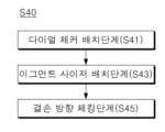
본 발명의 목적은 제1면을 기준으로 관절와의 결손된 부분의 방향과 결손량을 확인하는 결손부 측정단계를 포함하며, 상기 결손부 측정단계는, 결손부 깊이를 측정하도록 구비된 어그먼트 사이저를 통해 관절와의 중앙 부분으로부터 관절와 결손부의 최저점까지의 제1축 방향으로의 거리를 측정하는 어그먼트 사이저 배치단계, 관절와의 중앙 부분을 기준으로 최저점이 형성된 방향을 측정하는 결손방향 체킹단계를 포함하야 관절와의 뼈 결손량과 결손방향을 정확히 파악할 수 있는 관절와 베이스플레이트 삽입 방법을 제공하는 것이다.The purpose of the present invention includes a defect measurement step of confirming the direction and amount of defect of the defective portion of the joint fossa with respect to the first surface, and the defect measurement step is performed between augments provided to measure the depth of the defect. Through me, the augmentation sizer placement step of measuring the distance in the first axis direction from the center of the glenoid to the lowest point of the glenoid defect, and the defect direction checking step of measuring the direction in which the lowest point was formed based on the center of the glenoid fossa. The goal is to provide a glenoid base plate insertion method that can accurately determine the amount and direction of bone defect in the glenoid bone.
본 발명의 목적은 상기 결손부 측정단계는, 결손부 깊이를 측정하도록 구비된 어그먼트 사이저를 통해 제1면으로부터 관절와 결손부의 최저점까지의 제1축 방향으로의 거리를 측정하는 어그먼트 사이저 배치단계, 관절와의 중앙 부분을 기준으로 최저점이 형성된 방향을 측정하는 결손방향 체킹단계를 포함하여 하나의 수술기구로 결손부의 뼈 결손량과 결손방향을 파악할 수 있는 관절와 베이스플레이트 삽입 방법을 제공하는 것이다.The purpose of the present invention is to measure the distance in the first axis direction from the first surface to the lowest point of the glenoid defect through an augment sizer provided to measure the depth of the defect. It provides a glenoid base plate insertion method that can determine the amount and direction of bone defect in the defect area with a single surgical instrument, including a placement step and a defect direction checking step of measuring the direction in which the lowest point is formed based on the central part of the glenoid fossa. .
본 발명의 목적은 상기 결손부 측정단계는, 상기 어그먼트 사이저 배치단계 이전에 관절와의 중앙 부분을 기준으로 방향을 나타내는 다이얼 체커를 관절와 상에 배치하는 다이얼 체커 배치단계를 포함하고, 상기 결손방향 체킹단계는 상기 최저점과 접촉하는 어그먼트 사이저의 일부분이 상기 다이얼 체커 상에서 향하는 방향을 최저점이 형성된 방향으로 결정하여 수술의가 관절와의 최저점이 관절와 중심으로부터 어떤 방향에 형성된 것인지 빠르고 명확하게 인지할 수 있는 관절와 베이스플레이트 삽입 방법을 제공하는 것이다.An object of the present invention is that the defect measuring step includes a dial checker placement step of disposing a dial checker indicating a direction based on the central portion of the glenoid fossa on the glenoid before the augment sizer placement step, and the defect direction. In the checking step, the direction in which the part of the augmentation sizer in contact with the lowest point faces on the dial checker is determined as the direction in which the lowest point is formed, so that the surgeon can quickly and clearly recognize in what direction from the center of the glenoid the lowest point of the glenoid fossa is formed. It provides a base plate insertion method.
본 발명의 목적은 상기 어그먼트 사이저 배치단계는, 상기 어그먼트 사이저의 일부분이 상기 최저점과 접촉함과 동시에, 어그먼트 사이저의 일면이 다이얼 체커의 일면과 접촉하는 어그먼트 사이저를 상기 다이얼 체커 상에 배치함으로써 뼈 결손량에 따라 적합한 어그먼트 사이저를 사용할 수 있도록 하는 관절와 베이스플레이트 삽입 방법을 제공하는 것이다.The purpose of the present invention is to place the augment sizer in such a way that a portion of the augment sizer is in contact with the lowest point and at the same time, one surface of the augment sizer is in contact with one surface of the dial checker. It provides a glenoid base plate insertion method that allows the use of an appropriate augment sizer according to the amount of bone defect by placing it on the bone defect.
본 발명의 목적은 관절와의 절삭을 가이드하는 리밍가이드를 관절와에 삽입하는 리밍가이드 삽입단계를 더 포함하고, 상기 리밍가이드 삽입단계는, 리밍가이드를 리밍가이드 홀더에 체결하는 리밍가이드 체결단계, 상기 리밍가이드 홀더의 일측면에 기준 지시자를 연결하는 기준 지시자 체결단계, 상기 기준 지시자를 제1위치로 움직임으로써 상기 리밍가이드 홀더에 체결된 리밍가이드의 삽입포지션을 정렬하는 방향정렬단계를 포함하여 관절와의 절삭을 명확히 안내할 수 있는 관절와 베이스플레이트 삽입 방법을 제공하는 것이다.The object of the present invention further includes a reaming guide insertion step of inserting a reaming guide for guiding cutting of the glenoid fossa into the glenoid fossa, wherein the reaming guide insertion step includes a reaming guide fastening step of fastening the reaming guide to the reaming guide holder, and the reaming guide insertion step of inserting the reaming guide into the glenoid fossa. Cutting of the joint fossa, including a reference indicator fastening step of connecting a reference indicator to one side of the guide holder, and a direction alignment step of aligning the insertion position of the reaming guide fastened to the reaming guide holder by moving the reference indicator to a first position. The goal is to provide a glenoid base plate insertion method that can clearly guide the.
본 발명의 목적은 상기 다이얼 체커는 일면에 방향을 판별할 수 있도록 표시되거나 형성된 지시자를 포함하고, 상기 기준 지시자 체결단계는, 상기 기준 지시자를 상기 결손방향 체킹단계에서 확인한 지시자가 나타내는 방향으로 리밍가이드 홀더에 삽입하도록 함으로써 측정된 관절와의 뼈 결손방향대로 리밍가이드를 관절와에 삽입할 수 있는 관절와 베이스플레이트 삽입 방법을 제공하는 것이다.The object of the present invention is that the dial checker includes an indicator displayed or formed on one side so as to be able to determine the direction, and in the step of fastening the reference indicator, the reaming guide guides the reference indicator in the direction indicated by the indicator identified in the step of checking the defect direction. It provides a glenoid base plate insertion method that allows the reaming guide to be inserted into the glenoid fossa in the direction of the measured glenoid bone defect by inserting it into the holder.
본 발명의 목적은 상기 방향정렬단계는 기준 지시자가 수용된 리밍가이드 홀더가 제1축 상에 위치한 상태에서, 기준 지시자의 일단이 하측 방향으로 향하도록, 기준 지시자와 리밍가이드 홀더를 제1축을 중심으로 회전시킴으로써 수술의가 결손방향을 어림잡지 않고 정확한 기준에 따라 리밍가이드의 삽입포지션을 정렬하는 관절와 베이스플레이트 삽입 방법을 제공하는 것이다.The purpose of the present invention is to perform the direction alignment step by aligning the reference indicator and the reaming guide holder around the first axis so that one end of the reference indicator is directed downward while the reaming guide holder accommodating the reference indicator is located on the first axis. By rotating, it provides a glenoid base plate insertion method in which the surgeon aligns the insertion position of the reaming guide according to accurate standards without having to guess the direction of the defect.
본 발명의 목적은 일부분이 보강된 베이스플레이트를 관절와에 삽입하는 베이스플레이트 삽입단계를 더 포함하고, 상기 베이스플레이트 삽입단계는 일부분이 보강된 베이스플레이트를 베이스플레이트 홀더에 체결하는 베이스플레이트 체결단계, 상기 베이스플레이트 홀더의 일측면에 기준 지시자를 연결하는 기준 지시자 체결단계, 상기 기준 지시자를 제1위치로 움직임으로써 상기 베이스플레이트 홀더에 체결된 베이스플레이트의 삽입포지션을 정렬하고 베이스플레이트를 삽입하는 정렬삽입단계를 포함하여 일부분이 보강된 베이스플레이트를 간단하고 정확하게 관절와에 삽입할 수 있는 관절와 베이스플레이트 삽입 방법을 제공하는 것이다.An object of the present invention further includes a base plate insertion step of inserting a partially reinforced base plate into the glenoid, wherein the base plate insertion step includes a base plate fastening step of fastening the partially reinforced base plate to a base plate holder, A reference indicator fastening step of connecting a reference indicator to one side of the base plate holder, an alignment insertion step of aligning the insertion position of the base plate fastened to the base plate holder and inserting the base plate by moving the reference indicator to a first position. The aim is to provide a glenoid base plate insertion method that can simply and accurately insert a partially reinforced base plate into the glenoid.
본 발명은 앞서 본 목적을 달성하기 위해서 다음과 같은 구성을 가진 실시예에 의해서 구현된다.In order to achieve the above-described object, the present invention is implemented by an embodiment having the following configuration.
본 발명의 일 실시예에 따르면, 본 발명은 적어도 일부가 뼈의 표면을 면하면서 뼈에 대해 적어도 일시적으로 고정되는 다이얼 체커, 상기 다이얼 체커의 일측에 배치되어 뼈의 중앙 부분으로부터 결손된 부분의 방향과 결손량을 확인하는 어그먼트 사이저를 포함하는 것을 특징으로 한다.According to one embodiment of the present invention, the present invention provides a dial checker that is at least temporarily fixed to the bone while at least a portion faces the surface of the bone, and is disposed on one side of the dial checker to direct the defected portion from the center of the bone. and an augment sizer that checks the amount of defects.
본 발명의 일 실시예에 따르면, 상기 다이얼 체커는 제1축 방향으로 연장되는 로드, 상기 로드의 일측에서 적어도 방사상으로 연장되는 디스크를 포함하고, 상기 어그먼트 사이저는 상기 다이얼 체커와 동축정렬되어 제1축을 기준으로 회전하면서 일단이 뼈의 최저점에 접촉할 수 있도록 구비되는 것을 특징으로 한다.According to one embodiment of the present invention, the dial checker includes a rod extending in a first axis direction and a disk extending at least radially from one side of the rod, and the augmentation sizer is coaxially aligned with the dial checker. It is characterized by being provided so that one end can contact the lowest point of the bone while rotating about one axis.
본 발명의 일 실시예에 따르면, 상기 어그먼트 사이저는 일면에 실질적으로 평평한 접촉면을 가지며 상기 디스크 상에서 상기 제1축을 기준으로 회전할 수 있도록 구비된 회전자, 상기 회전자의 일측에서 연장되는 레그를 포함하고, 상기 레그의 엔드포인트가 뼈에 닿으면서 동시에 상기 회전자의 접촉면이 디스크의 일면과 접촉하는 것을 특징으로 한다.According to one embodiment of the present invention, the augment sizer includes a rotor that has a substantially flat contact surface on one surface and is capable of rotating about the first axis on the disk, and a leg extending from one side of the rotor. It is characterized in that the end point of the leg touches the bone and at the same time, the contact surface of the rotor contacts one surface of the disc.
본 발명의 일 실시예에 따르면, 상기 디스크는 뼈를 면하지 않는 일면에 방향을 판별할 수 있도록 표시되는 지시자를 포함하고, 상기 어그먼트 사이저의 레그가 향하는 방향이 상기 지시자에 의해 지시되는 것을 특징으로 한다.According to one embodiment of the present invention, the disc includes an indicator displayed on one side that does not face the bone to help determine the direction, and the direction in which the leg of the augmentation sizer faces is indicated by the indicator. Do it as
본 발명의 일 실시예에 따르면, 상기 디스크는 외주면이 교번적으로 돌출 및 함입형성되는 디스크바디를 포함하는 것을 특징으로 한다.According to one embodiment of the present invention, the disk is characterized in that it includes a disk body whose outer peripheral surface is alternately protruded and recessed.
본 발명의 일 실시예에 따르면, 상기 디스크는 상기 디스크를 관통하며 형성된 적어도 하나 이상의 정렬홀을 더 포함하며, 상기 정렬홀은 상하로 연장되는 장공인 것을 특징으로 한다.According to one embodiment of the present invention, the disk further includes at least one alignment hole formed penetrating the disk, and the alignment hole is characterized as a long hole extending up and down.
본 발명의 일 실시예에 따르면, 상기 디스크는 뼈를 면하는 일면 상에 돌출형성된 적어도 하나 이상의 스파이크를 더 포함하는 것을 특징으로 한다.According to one embodiment of the present invention, the disc is characterized in that it further includes at least one spike protruding on one surface facing the bone.
본 발명의 일 실시예에 따르면, 상기 로드와 어그먼트 사이저의 적어도 일부를 수용하는 사이저 핸들을 더 포함하고, 상기 사이저 핸들은 상기 로드를 관통수용하는 관통공, 내부에 수용공간을 형성하면서 어그먼트 사이저의 일부를 수용하는 수용부분을 포함하여 어그먼트 사이저와 사이저 핸들이 함께 제1축을 중심으로 회전할 수 있도록 구비되는 것을 특징으로 한다.According to one embodiment of the present invention, it further includes a sizer handle accommodating at least a portion of the rod and the augmentation sizer, wherein the sizer handle has a through hole for penetrating and accommodating the rod, and forms an accommodating space therein. It is characterized in that the augment sizer and the sizer handle, including a receiving portion that accommodates a part of the augment sizer, are provided so that they can rotate about the first axis.
본 발명의 일 실시예에 따르면, 상기 다이얼 체커는 뼈에 삽입되어 제1축 방향으로 연장되는 가이드핀을 관통수용하도록 중공을 가지는 것을 특징으로 한다.According to one embodiment of the present invention, the dial checker is characterized by having a hollow hole to accommodate a guide pin inserted into the bone and extending in the first axis direction.
본 발명의 일 실시예에 따르면, 본 발명은 뼈에 삽입되어 뼈의 절삭을 가이드하는 리밍가이드와 적어도 일시적으로 체결되어 상기 리밍가이드의 삽입포지션을 결정하며, 상기 리밍가이드가 뼈에 삽입될 때 상기 리밍가이드의 일부분이 향하는 방향을 결정하는 삽입포지션 결정부, 상기 리밍가이드와 적어도 일시적으로 체결되는 체결부를 포함하는 것을 특징으로 한다.According to one embodiment of the present invention, the present invention is at least temporarily engaged with a reaming guide that is inserted into the bone and guides the cutting of the bone to determine the insertion position of the reaming guide, and when the reaming guide is inserted into the bone, It is characterized by comprising an insertion position determining part that determines the direction in which a portion of the reaming guide faces, and a fastening part that is at least temporarily fastened to the reaming guide.
본 발명의 일 실시예에 따르면, 상기 삽입포지션 결정부는 적어도 일부가 제1축 방향으로 연장되는 바디, 상기 바디의 일측에서 상기 리밍가이드의 삽입포지션을 정렬하는 정렬부를 포함하고, 상기 정렬부는 일면에 대응지시자가 방사상으로 표시되거나 형성되는 것을 특징으로 한다.According to one embodiment of the present invention, the insertion position determination unit includes a body at least partially extending in the first axis direction, an alignment unit for aligning the insertion position of the reaming guide on one side of the body, and the alignment unit is on one side. It is characterized in that the corresponding indicator is displayed or formed radially.
본 발명의 일 실시예에 따르면, 상기 정렬부는 소정 두께를 가지며 형성되는 디스크, 상기 디스크의 외주면에 함입형성되는 복수의 수용홈을 포함하고, 상기 수용홈의 개수와 대응되는 개수의 대응지시자가 수용홈이 형성된 부분에 대응되어 표시되는 것을 특징으로 한다.According to one embodiment of the present invention, the alignment unit includes a disk formed to have a predetermined thickness, a plurality of receiving grooves recessed into the outer peripheral surface of the disk, and a number of corresponding indicators corresponding to the number of the receiving grooves are accommodated. It is characterized in that it is displayed corresponding to the portion where the groove is formed.
본 발명의 일 실시예에 따르면, 상기 바디의 일측에서 연장되는 정렬레그를 더 포함하고,According to one embodiment of the present invention, it further includes an alignment leg extending from one side of the body,
상기 정렬레그는 중간에 갭을 형성하면서 두갈래로 갈라지는 레그, 상기 레그의 일단에서 절곡연장되는 절곡부를 가져 상기 갭에 리밍가이드의 일부를 수용하는 것을 특징으로 한다.The alignment leg is characterized in that it has a leg that is divided into two while forming a gap in the middle, and a bent portion that is bent and extended from one end of the leg to accommodate a part of the reaming guide in the gap.
본 발명의 일 실시예에 따르면, 상기 리밍가이드가 상기 리밍가이드 홀더에 대해 회전하지 않도록 하는 고정레그를 더 포함하고, 상기 고정레그는 바디의 일측에서 연장되며 단부에 핀을 형성하는 것을 특징으로 한다.According to one embodiment of the present invention, the reaming guide further includes a fixing leg that prevents the reaming guide from rotating with respect to the reaming guide holder, and the fixing leg extends from one side of the body and forms a pin at the end. .
본 발명의 일 실시예에 따르면, 상기 삽입포지션 결정부 및 체결부와 동축정렬되는 나사 드라이버를 더 포함하며, 상기 나사 드라이버는 상기 나사 드라이버가 전진하는 경우 상기 체결부의 일단보다 돌출되고, 후진하는 경우 체결부 내에 수용되는 팁을 포함하는 것을 특징으로 한다.According to one embodiment of the present invention, it further includes a screw driver coaxially aligned with the insertion position determining part and the fastening part, wherein the screw driver protrudes beyond one end of the fastening part when the screw driver moves forward, and when the screw driver moves forward, the screw driver protrudes beyond one end of the fastening part. It is characterized by including a tip accommodated within the fastening portion.
본 발명의 일 실시예에 따르면, 본 발명은 일부분이 보강된 관절와 베이스플레이트와 일시적으로 체결되어 상기 베이스플레이트의 삽입포지션을 결정하여 뼈에 삽입하는 베이스플레이트 홀더로서, 적어도 일부가 제1축 방향으로 연장되는 바디, 상기 바디의 일측에서 베이스플레이트에 적어도 일부가 삽입되는 삽입단 및 상기 바디의 타측에 마련되어 상기 베이스플레이트의 삽입포지션을 정렬하는 정렬부를 포함하는 것을 특징으로 한다.According to one embodiment of the present invention, the present invention is a base plate holder that is temporarily fastened to a partially reinforced glenoid base plate to determine the insertion position of the base plate and inserted into the bone, at least a portion of which is oriented in the first axis direction. It is characterized by comprising an extending body, an insertion end at least partially inserted into the base plate on one side of the body, and an alignment portion provided on the other side of the body to align the insertion position of the base plate.
본 발명의 일 실시예에 따르면, 상기 정렬부는 소정 두께를 가지며 형성되는 디스크, 상기 디스크의 외주면에 함입형성되는 복수의 수용홈, 상기 디스크의 일면에 방사상으로 표시되거나 형성된 대응지시자를 포함하는 것을 특징으로 한다.According to one embodiment of the present invention, the alignment portion includes a disk formed to have a predetermined thickness, a plurality of receiving grooves recessed into the outer peripheral surface of the disk, and a corresponding indicator displayed or formed radially on one surface of the disk. Do it as
본 발명의 일 실시예에 따르면, 상기 수용홈의 개수와 대응되는 개수의 대응지시자가 수용홈이 형성된 부분에 대응되어 표시되는 것을 특징으로 한다.According to one embodiment of the present invention, a number of corresponding indicators corresponding to the number of the receiving grooves is displayed in correspondence with the portion where the receiving grooves are formed.
본 발명의 일 실시예에 따르면, 상기 삽입단은 상기 삽입단으로부터 돌출형성되어 상기 베이스플레이트에 삽입되는 삽입돌기와, 상기 베이스플레이트와 베이스플레이트 홀더의 체결방향을 지시하도록 표시되는 삽입지시자를 포함하는 것을 특징으로 한다.According to one embodiment of the present invention, the insertion end includes an insertion protrusion that protrudes from the insertion end and is inserted into the base plate, and an insertion indicator displayed to indicate the fastening direction of the base plate and the base plate holder. It is characterized by
본 발명의 일 실시예에 따르면, 베이스플레이트와 베이스플레이트 홀더 사이의 체결을 보조하는 체결보조부를 더 포함하고, 상기 체결보조부는 상기 삽입돌기와 함께 베이스플레이트에 삽입되는 보조돌기, 적어도 일부가 바디 외부로 노출되는 회전체, 상기 회전체와 보조돌기를 연결하여 회전력을 보조돌기로 전달하는 연결로드를 포함하는 것을 특징으로 한다.According to one embodiment of the present invention, it further includes a fastening auxiliary part that assists fastening between the base plate and the base plate holder, and the fastening auxiliary part has an auxiliary protrusion inserted into the base plate together with the insertion protrusion, at least a portion of which is outside the body. It is characterized by comprising an exposed rotating body and a connecting rod that connects the rotating body and the auxiliary protrusion to transmit rotational force to the auxiliary protrusion.
본 발명의 일 실시예에 따르면, 제1면을 기준으로 관절와의 결손된 부분의 방향과 결손량을 확인하는 결손부 측정단계를 포함하며, 상기 결손부 측정단계는, 결손부 깊이를 측정하도록 구비된 어그먼트 사이저를 통해 관절와의 중앙 부분으로부터 관절와 결손부의 최저점까지의 제1축 방향으로의 거리를 측정하는 어그먼트 사이저 배치단계, 관절와의 중앙 부분을 기준으로 최저점이 형성된 방향을 측정하는 결손방향 체킹단계를 포함하는 것을 특징으로 한다.According to one embodiment of the present invention, it includes a defect measurement step of confirming the direction and amount of defect of the defective portion of the glenoid with respect to the first surface, and the defect measurement step is provided to measure the depth of the defect. Augment sizer placement step of measuring the distance in the first axis direction from the central part of the glenoid to the lowest point of the glenoid defect using the augment sizer, measuring the direction in which the lowest point was formed based on the central part of the glenoid fossa. It is characterized by including a direction checking step.
본 발명의 일 실시예에 따르면, 상기 결손부 측정단계는, 상기 어그먼트 사이저 배치단계 이전에 관절와의 중앙 부분을 기준으로 방향을 나타내는 다이얼 체커를 관절와 상에 배치하는 다이얼 체커 배치단계를 포함하고, 상기 결손방향 체킹단계는 상기 최저점과 접촉하는 어그먼트 사이저의 일부분이 상기 다이얼 체커 상에서 향하는 방향을 최저점이 형성된 방향으로 결정하는 것을 특징으로 한다.According to one embodiment of the present invention, the defect measuring step includes a dial checker placement step of placing a dial checker indicating a direction based on the central portion of the glenoid fossa on the glenoid before the augmentation sizer placement step; , The defect direction checking step is characterized in that the direction in which the portion of the augmentation sizer in contact with the lowest point faces on the dial checker is determined as the direction in which the lowest point was formed.
본 발명의 일 실시예에 따르면, 상기 어그먼트 사이저 배치단계는, 상기 어그먼트 사이저의 일부분이 상기 최저점과 접촉함과 동시에, 어그먼트 사이저의 일면이 다이얼 체커의 일면과 접촉하는 어그먼트 사이저를 상기 다이얼 체커 상에 배치하는 것을 특징으로 한다.According to one embodiment of the present invention, in the augmentation sizer arrangement step, a portion of the augmentation sizer is in contact with the lowest point, and at the same time, one surface of the augmentation sizer is in contact with one surface of the dial checker. characterized in that it is disposed on the dial checker.
본 발명의 일 실시예에 따르면, 관절와의 절삭을 가이드하는 리밍가이드를 관절와에 삽입하는 리밍가이드 삽입단계를 더 포함하고, 상기 리밍가이드 삽입단계는, 리밍가이드를 리밍가이드 홀더에 체결하는 리밍가이드 체결단계, 상기 리밍가이드 홀더의 일측면에 기준 지시자를 연결하는 기준 지시자 체결단계, 상기 기준 지시자를 제1위치로 움직임으로써 상기 리밍가이드 홀더에 체결된 리밍가이드의 삽입포지션을 정렬하는 방향정렬단계를 포함하는 것을 특징으로 한다.According to one embodiment of the present invention, it further includes a reaming guide insertion step of inserting a reaming guide for guiding cutting of the glenoid fossa into the glenoid fossa, wherein the reaming guide insertion step includes fastening the reaming guide to the reaming guide holder. Step, a reference indicator fastening step of connecting a reference indicator to one side of the reaming guide holder, and a direction alignment step of aligning the insertion position of the reaming guide fastened to the reaming guide holder by moving the reference indicator to a first position. It is characterized by:
본 발명의 일 실시예에 따르면, 상기 다이얼 체커는 일면에 방향을 판별할 수 있도록 표시되거나 형성된 지시자를 포함하고, 상기 기준 지시자 체결단계는, 상기 기준 지시자를 상기 결손방향 체킹단계에서 확인한 지시자가 나타내는 방향으로 리밍가이드 홀더에 삽입하는 것을 특징으로 한다.According to one embodiment of the present invention, the dial checker includes an indicator displayed or formed on one side so as to be able to determine the direction, and the reference indicator fastening step indicates that the reference indicator is indicated by an indicator confirmed in the defect direction checking step. It is characterized by inserting it into the reaming guide holder in one direction.
본 발명의 일 실시예에 따르면, 상기 방향정렬단계는 기준 지시자가 수용된 리밍가이드 홀더가 제1축 상에 위치한 상태에서, 기준 지시자의 일단이 하측 방향으로 향하도록, 기준 지시자와 리밍가이드 홀더를 제1축을 중심으로 회전시키는 것을 특징으로 한다.According to one embodiment of the present invention, the direction alignment step is performed by aligning the reference indicator and the reaming guide holder so that one end of the reference indicator is directed downward, with the reaming guide holder accommodating the reference indicator located on the first axis. It is characterized by rotating around one axis.
본 발명의 일 실시예에 따르면, 일부분이 보강된 베이스플레이트를 관절와에 삽입하는 베이스플레이트 삽입단계를 더 포함하고, 상기 베이스플레이트 삽입단계는 일부분이 보강된 베이스플레이트를 베이스플레이트 홀더에 체결하는 베이스플레이트 체결단계, 상기 베이스플레이트 홀더의 일측면에 기준 지시자를 연결하는 기준 지시자 체결단계, 상기 기준 지시자를 제1위치로 움직임으로써 상기 베이스플레이트 홀더에 체결된 베이스플레이트의 삽입포지션을 정렬하고 베이스플레이트를 삽입하는 정렬삽입단계를 포함하는 것을 특징으로 한다.According to one embodiment of the present invention, it further includes a base plate insertion step of inserting the partially reinforced base plate into the glenoid, and the base plate insertion step includes fastening the partially reinforced base plate to the base plate holder. A fastening step, a reference indicator fastening step of connecting a reference indicator to one side of the base plate holder, aligning the insertion position of the base plate fastened to the base plate holder by moving the reference indicator to a first position and inserting the base plate. It is characterized in that it includes an alignment insertion step.
본 발명은 앞서 본 실시예와 하기에 설명할 구성과 결합, 사용관계에 의해 다음과 같은 효과를 얻을 수 있다.The present invention can achieve the following effects by combining the above-mentioned embodiment with the configuration, combination, and use relationship described below.
본 발명은, 적어도 일부가 뼈의 표면을 면하면서 뼈에 대해 적어도 일시적으로 고정되는 다이얼 체커, 상기 다이얼 체커의 일측에 배치되어 뼈의 중앙 부분으로부터 결손된 부분의 방향과 결손량을 확인하는 어그먼트 사이저를 포함하도록 하여 관절와의 뼈 결손량과 결손방향을 정확하게 알 수 있다.The present invention relates to a dial checker that is at least temporarily fixed to the bone while at least part of it faces the surface of the bone, and an augment that is disposed on one side of the dial checker and checks the direction and amount of the defect from the central part of the bone. By including the sizer, the amount and direction of bone defect in the joint fossa can be accurately determined.
본 발명은, 상기 다이얼 체커는 제1축 방향으로 연장되는 로드, 상기 로드의 일측에서 적어도 방사상으로 연장되는 디스크를 포함하고, 상기 어그먼트 사이저는 상기 다이얼 체커와 동축정렬되어 제1축을 기준으로 회전하면서 일단이 뼈의 최저점에 접촉할 수 있도록 구비함으로써 수술의가 어그먼트 사이저를 회전시키면서 뼈에 최저점에 닿은 방향을 결손방향으로 파악할 수 있다.In the present invention, the dial checker includes a rod extending in a first axis direction and a disk extending at least radially from one side of the rod, and the augmentation sizer is coaxially aligned with the dial checker and rotates about the first axis. By providing one end to contact the lowest point of the bone while rotating the augmentation sizer, the surgeon can determine the direction in which the augmentation sizer touches the lowest point of the bone as the direction of the defect.
본 발명은, 상기 어그먼트 사이저는 일면에 실질적으로 평평한 접촉면을 가지며 상기 디스크 상에서 상기 제1축을 기준으로 회전할 수 있도록 구비된 회전자, 상기 회전자의 일측에서 연장되는 레그를 포함하고, 상기 레그의 엔드포인트가 뼈에 닿으면서 동시에 상기 회전자의 접촉면이 디스크의 일면과 접촉하도록 함으로써 정확한 뼈 결손량을 파악할 수 있다.In the present invention, the augmentation sizer includes a rotor having a substantially flat contact surface on one surface and rotatable about the first axis on the disk, a leg extending from one side of the rotor, and the leg The exact amount of bone defect can be determined by having the endpoint of the rotor contact the bone and at the same time the contact surface of the rotor contact one surface of the disc.
본 발명은, 상기 디스크는 뼈를 면하지 않는 일면에 방향을 판별할 수 있도록 표시되는 지시자를 포함하고, 상기 어그먼트 사이저의 레그가 향하는 방향이 상기 지시자에 의해 지시됨으로써 수술의가 육안으로 정확한 뼈 결손방향을 파악할 수 있다.In the present invention, the disc includes an indicator displayed on one side that does not face the bone to enable the direction to be determined, and the direction in which the leg of the augmentation sizer faces is indicated by the indicator so that the surgeon can accurately determine the bone defect with the naked eye. You can figure out the direction.
본 발명은, 상기 디스크는 외주면이 교번적으로 돌출 및 함입형성되는 디스크바디를 포함하여 어그먼트 사이저와 함께 결손방향을 더욱 용이하게 파악할 수 있다.In the present invention, the disc includes a disc body whose outer peripheral surface is alternately protruded and recessed, so that the direction of the defect can be more easily determined with the augmentation sizer.
본 발명은, 상기 디스크는 상기 디스크를 관통하며 형성된 적어도 하나 이상의 정렬홀을 더 포함하며, 상기 정렬홀은 상하로 연장되는 장공이도록 하여 관절와에 표시된 랜드마크를 기준으로 결손부 측정기구의 삽입포지션 정렬이 가능하다.In the present invention, the disc further includes at least one alignment hole formed penetrating the disc, and the alignment hole is a long hole extending up and down to align the insertion position of the defect measuring device based on a landmark displayed on the glenoid. This is possible.
본 발명은, 상기 디스크는 뼈를 면하는 일면 상에 돌출형성된 적어도 하나 이상의 스파이크를 포함하여 관절와에 대한 고정력이 증대된다.In the present invention, the disc includes at least one spike protruding on one surface facing the bone, thereby increasing the fixing force to the glenoid fossa.
본 발명은, 상기 로드와 어그먼트 사이저의 적어도 일부를 수용하는 사이저 핸들을 더 포함하고, 상기 사이저 핸들은 상기 로드를 관통수용하는 관통공, 내부에 수용공간을 형성하면서 어그먼트 사이저의 일부를 수용하는 수용부분을 포함하여 어그먼트 사이저와 사이저 핸들이 함께 제1축을 중심으로 회전할 수 있도록 구비하여 용이한 작업이 가능하다.The present invention further includes a sizer handle for accommodating at least a portion of the rod and the augmentation sizer, wherein the sizer handle includes a through hole for penetrating and receiving the rod, and a portion of the augmentation sizer while forming a receiving space therein. Easy work is possible because the augment sizer and the sizer handle, including a receiving part that accommodates, are provided so that they can rotate around the first axis.
본 발명은, 상기 다이얼 체커는 뼈에 삽입되어 제1축 방향으로 연장되는 가이드핀을 관통수용하도록 중공을 가지도록 함으로써 관절와에 삽입된 가이드핀을 제거하지 않고 결손량과 결손방향을 확인할 수 있다.In the present invention, the dial checker has a hollow hole to accommodate a guide pin inserted into the bone and extending in the first axis direction, so that the amount and direction of the defect can be confirmed without removing the guide pin inserted into the glenoid.
본 발명은, 뼈에 삽입되어 뼈의 절삭을 가이드하는 리밍가이드와 적어도 일시적으로 체결되어 상기 리밍가이드의 삽입포지션을 결정하며, 상기 리밍가이드가 뼈에 삽입될 때 상기 리밍가이드의 일부분이 향하는 방향을 결정하는 삽입포지션 결정부, 상기 리밍가이드와 적어도 일시적으로 체결되는 체결부를 포함하여 리밍가이드의 삽입포지션을 정렬하여 관절와에 삽입하도록 한다.The present invention is at least temporarily engaged with a reaming guide that is inserted into the bone and guides the cutting of the bone to determine the insertion position of the reaming guide, and determines the direction in which a portion of the reaming guide faces when the reaming guide is inserted into the bone. Aligning the insertion position of the reaming guide, including an insertion position determining part and a fastening part that is at least temporarily fastened to the reaming guide, allows the reaming guide to be inserted into the glenoid fossa.
본 발명은, 상기 삽입포지션 결정부는 적어도 일부가 제1축 방향으로 연장되는 바디, 상기 바디의 일측에서 상기 리밍가이드의 삽입포지션을 정렬하는 정렬부를 포함하고, 상기 정렬부는 일면에 대응지시자가 방사상으로 표시되거나 형성되도록 함으로써 뼈의 결손방향에 따라 리밍가이드의 삽입포지션 정렬이 가능한 효과를 준다.In the present invention, the insertion position determination unit includes a body at least partially extending in the first axis direction, an alignment unit for aligning the insertion position of the reaming guide on one side of the body, and the alignment unit has a corresponding indicator radially on one side. By marking or forming it, it is possible to align the insertion position of the reaming guide according to the direction of the bone defect.
본 발명은, 상기 정렬부는 소정 두께를 가지며 형성되는 디스크, 상기 디스크의 외주면에 함입형성되는 복수의 수용홈을 포함하고, 상기 수용홈의 개수와 대응되는 개수의 대응지시자가 수용홈이 형성된 부분에 대응되어 표시되도록 함으로써 리밍가이드 홀더를 정확한 방향으로 회전시켜 리밍가이드의 삽입방향을 정렬할 수 있다.In the present invention, the alignment portion includes a disk formed to have a predetermined thickness, a plurality of receiving grooves recessed into the outer peripheral surface of the disk, and a number of corresponding indicators corresponding to the number of the receiving grooves is placed on the portion where the receiving grooves are formed. By displaying them in correspondence, the insertion direction of the reaming guide can be aligned by rotating the reaming guide holder in the correct direction.
본 발명은, 상기 바디의 일측에서 연장되는 정렬레그를 더 포함하고, 상기 정렬레그는 중간에 갭을 형성하면서 두갈래로 갈라지는 레그, 상기 레그의 일단에서 절곡연장되는 절곡부를 가져 상기 갭에 리밍가이드의 일부를 수용하도록 함으로써 리밍가이드와 일시적으로 체결됨과 동시에 리밍가이드의 삽입을 가이드할 수 있다.The present invention further includes an alignment leg extending from one side of the body, wherein the alignment leg is divided into two legs forming a gap in the middle, and has a bent portion bent and extended from one end of the leg, and a reaming guide in the gap. By accommodating a part of the reaming guide, it is possible to temporarily fasten it to the reaming guide and at the same time guide the insertion of the reaming guide.
본 발명은, 상기 리밍가이드가 상기 리밍가이드 홀더에 대해 회전하지 않도록 하는 고정레그를 더 포함하고, 상기 고정레그는 바디의 일측에서 연장되며 단부에 핀을 형성하는 리밍가이드 홀더를 제공하는 효과를 가진다.The present invention further includes a fixing leg that prevents the reaming guide from rotating with respect to the reaming guide holder, and the fixing leg extends from one side of the body and has the effect of providing a reaming guide holder forming a pin at the end. .
본 발명은, 상기 삽입포지션 결정부 및 체결부와 동축정렬되는 나사 드라이버를 더 포함하며, 상기 나사 드라이버는 상기 나사 드라이버가 전진하는 경우 상기 체결부의 일단보다 돌출되고, 후진하는 경우 체결부 내에 수용되는 팁을 포함하여 하나의 수술기구로 여러 작업이 가능하다.The present invention further includes a screw driver coaxially aligned with the insertion position determination part and the fastening part, wherein the screw driver protrudes beyond one end of the fastening part when the screw driver moves forward and is accommodated in the fastening part when the screw driver moves backward. Multiple operations are possible with one surgical instrument, including the tip.
본 발명은, 일부분이 보강된 관절와 베이스플레이트와 일시적으로 체결되어 상기 베이스플레이트의 삽입포지션을 결정하여 뼈에 삽입하는 베이스플레이트 홀더로서, 적어도 일부가 제1축 방향으로 연장되는 바디, 상기 바디의 일측에서 베이스플레이트에 적어도 일부가 삽입되는 삽입단 및 상기 바디의 타측에 마련되어 상기 베이스플레이트의 삽입포지션을 정렬하는 정렬부를 포함하여 일부분이 보강된 베이스플레이트의 삽입포지션을 정렬하여 관절와에 삽입하는 베이스플레이트 홀더를 제공하는 효과를 도출한다.The present invention is a base plate holder that is temporarily fastened to a partially reinforced glenoid base plate to determine the insertion position of the base plate and is inserted into the bone, comprising: a body at least partially extending in a first axis direction; one side of the body; A base plate holder that aligns the insertion position of the partially reinforced base plate and inserts it into the glenoid, including an insertion end at least partially inserted into the base plate and an alignment portion provided on the other side of the body to align the insertion position of the base plate. Derive the effect that provides.
본 발명은, 상기 정렬부는 소정 두께를 가지며 형성되는 디스크, 상기 디스크의 외주면에 함입형성되는 복수의 수용홈, 상기 디스크의 일면에 방사상으로 표시되거나 형성된 대응지시자를 포함하도록 함으로써 베이스플레이트 홀더를 정확한 방향으로 회전시켜 베이스플레이트의 삽입방향을 정렬할 수 있다.In the present invention, the alignment portion includes a disk formed to have a predetermined thickness, a plurality of receiving grooves recessed into the outer peripheral surface of the disk, and a corresponding indicator displayed or formed radially on one surface of the disk to accurately orient the base plate holder. You can align the insertion direction of the base plate by rotating it.
본 발명은, 상기 수용홈의 개수와 대응되는 개수의 대응지시자가 수용홈이 형성된 부분에 대응되어 표시되는 베이스플레이트 홀더를 제공하는 효과가 있다.The present invention has the effect of providing a base plate holder in which a number of corresponding indicators corresponding to the number of receiving grooves is displayed in correspondence with the portion where the receiving grooves are formed.
본 발명은, 상기 삽입단은 상기 삽입단으로부터 돌출형성되어 상기 베이스플레이트에 삽입되는 삽입돌기와, 상기 베이스플레이트와 베이스플레이트 홀더의 체결방향을 지시하도록 표시되는 삽입지시자를 포함하도록 함으로써 베이스플레이트를 올바른 방법으로 체결할 수 있다.The present invention provides a correct method of inserting the base plate by ensuring that the insertion end includes an insertion protrusion that protrudes from the insertion end and is inserted into the base plate, and an insertion indicator displayed to indicate the fastening direction of the base plate and the base plate holder. It can be concluded with
본 발명은, 베이스플레이트와 베이스플레이트 홀더 사이의 체결을 보조하는 체결보조부를 더 포함하고, 상기 체결보조부는 상기 삽입돌기와 함께 베이스플레이트에 삽입되는 보조돌기, 적어도 일부가 바디 외부로 노출되는 회전체, 상기 회전체와 보조돌기를 연결하여 회전력을 보조돌기로 전달하는 연결로드를 포함하도록 함으로써 베이스플레이트와 체결력이 증대되는 효과를 준다.The present invention further includes a fastening auxiliary part that assists fastening between a base plate and a base plate holder, wherein the fastening auxiliary part includes an auxiliary protrusion inserted into the base plate together with the insertion protrusion, a rotating body at least a portion of which is exposed to the outside of the body, By including a connecting rod that connects the rotating body and the auxiliary protrusion and transmits rotational force to the auxiliary protrusion, the fastening force with the base plate is increased.
본 발명은, 제1면을 기준으로 관절와의 결손된 부분의 방향과 결손량을 확인하는 결손부 측정단계를 포함하며, 상기 결손부 측정단계는, 결손부 깊이를 측정하도록 구비된 어그먼트 사이저를 통해 관절와의 중앙 부분으로부터 관절와 결손부의 최저점까지의 제1축 방향으로의 거리를 측정하는 어그먼트 사이저 배치단계, 관절와의 중앙 부분을 기준으로 최저점이 형성된 방향을 측정하는 결손방향 체킹단계를 포함하야 관절와의 뼈 결손량과 결손방향을 정확히 파악할 수 있다.The present invention includes a defect measurement step of confirming the direction and amount of defect of the defective portion of the joint fossa based on the first surface, and the defect measurement step includes an augmentation sizer provided to measure the depth of the defect. It includes an augment sizer placement step of measuring the distance in the first axis direction from the central part of the glenoid to the lowest point of the glenoid defect, and a defect direction checking step of measuring the direction in which the lowest point is formed based on the central part of the glenoid. Only then can the amount and direction of bone defect in the joint fossa be accurately identified.
본 발명은, 상기 결손부 측정단계는, 결손부 깊이를 측정하도록 구비된 어그먼트 사이저를 통해 제1면으로부터 관절와 결손부의 최저점까지의 제1축 방향으로의 거리를 측정하는 어그먼트 사이저 배치단계, 관절와의 중앙 부분을 기준으로 최저점이 형성된 방향을 측정하는 결손방향 체킹단계를 포함하여 하나의 수술기구로 결손부의 뼈 결손량과 결손방향을 파악할 수 있다.In the present invention, the defect measuring step includes arranging an augment sizer to measure the distance in the first axis direction from the first surface to the lowest point of the glenoid defect through an augment sizer provided to measure the depth of the defect. Including the defect direction checking step of measuring the direction in which the lowest point is formed based on the central part of the glenoid fossa, the amount and direction of bone defect in the defect area can be determined with a single surgical instrument.
본 발명은, 상기 결손부 측정단계는, 상기 어그먼트 사이저 배치단계 이전에 관절와의 중앙 부분을 기준으로 방향을 나타내는 다이얼 체커를 관절와 상에 배치하는 다이얼 체커 배치단계를 포함하고, 상기 결손방향 체킹단계는 상기 최저점과 접촉하는 어그먼트 사이저의 일부분이 상기 다이얼 체커 상에서 향하는 방향을 최저점이 형성된 방향으로 결정하여 수술의가 관절와의 최저점이 관절와 중심으로부터 어떤 방향에 형성된 것인지 빠르고 명확하게 인지할 수 있다.In the present invention, the defect measurement step includes a dial checker placement step of placing a dial checker indicating a direction based on the central portion of the glenoid fossa on the glenoid before the augment sizer placement step, and checking the defect direction. In the step, the direction in which the part of the augmentation sizer in contact with the lowest point faces on the dial checker is determined as the direction in which the lowest point is formed, so that the surgeon can quickly and clearly recognize in what direction from the center of the glenoid the lowest point of the glenoid fossa is formed.
본 발명은, 상기 어그먼트 사이저 배치단계는, 상기 어그먼트 사이저의 일부분이 상기 최저점과 접촉함과 동시에, 어그먼트 사이저의 일면이 다이얼 체커의 일면과 접촉하는 어그먼트 사이저를 상기 다이얼 체커 상에 배치함으로써 뼈 결손량에 따라 적합한 어그먼트 사이저를 사용할 수 있도록 한다.In the present invention, the augmentation sizer arrangement step includes placing the augmentation sizer in which a portion of the augmentation sizer is in contact with the lowest point and at the same time, one surface of the augmentation sizer is in contact with one surface of the dial checker. By placing it in , it is possible to use an appropriate augment sizer depending on the amount of bone defect.
본 발명은, 관절와의 절삭을 가이드하는 리밍가이드를 관절와에 삽입하는 리밍가이드 삽입단계를 더 포함하고, 상기 리밍가이드 삽입단계는, 리밍가이드를 리밍가이드 홀더에 체결하는 리밍가이드 체결단계, 상기 리밍가이드 홀더의 일측면에 기준 지시자를 연결하는 기준 지시자 체결단계, 상기 기준 지시자를 제1위치로 움직임으로써 상기 리밍가이드 홀더에 체결된 리밍가이드의 삽입포지션을 정렬하는 방향정렬단계를 포함하여 관절와의 절삭을 명확히 안내할 수 있다.The present invention further includes a reaming guide insertion step of inserting a reaming guide for guiding cutting of the glenoid fossa into the glenoid fossa, wherein the reaming guide insertion step includes a reaming guide fastening step of fastening the reaming guide to a reaming guide holder, the reaming guide Cutting of the joint fossa, including a reference indicator fastening step of connecting the reference indicator to one side of the holder, and a direction alignment step of aligning the insertion position of the reaming guide fastened to the reaming guide holder by moving the reference indicator to the first position. We can provide clear guidance.
본 발명은, 상기 다이얼 체커는 일면에 방향을 판별할 수 있도록 표시되거나 형성된 지시자를 포함하고, 상기 기준 지시자 체결단계는, 상기 기준 지시자를 상기 결손방향 체킹단계에서 확인한 지시자가 나타내는 방향으로 리밍가이드 홀더에 삽입하도록 함으로써 측정된 관절와의 뼈 결손방향대로 리밍가이드를 관절와에 삽입할 수 있다.According to the present invention, the dial checker includes an indicator displayed or formed on one side so as to be able to determine the direction, and in the step of fastening the reference indicator, the reaming guide holder moves the reference indicator in the direction indicated by the indicator identified in the step of checking the defect direction. By inserting it into the glenoid, the reaming guide can be inserted into the glenoid in the direction of the glenoid bone defect measured.
본 발명은, 상기 방향정렬단계는 기준 지시자가 수용된 리밍가이드 홀더가 제1축 상에 위치한 상태에서, 기준 지시자의 일단이 하측 방향으로 향하도록, 기준 지시자와 리밍가이드 홀더를 제1축을 중심으로 회전시킴으로써 수술의가 결손방향을 어림잡지 않고 정확한 기준에 따라 리밍가이드의 삽입포지션을 정렬하는 효과를 가진다.In the present invention, the direction alignment step is performed by rotating the reference indicator and the reaming guide holder about the first axis so that one end of the reference indicator is directed downward while the reaming guide holder in which the reference indicator is accommodated is located on the first axis. By doing this, the surgeon has the effect of aligning the insertion position of the reaming guide according to accurate standards without having to guess the direction of the defect.
본 발명은, 베이스플레이트를 관절와에 삽입하는 베이스플레이트 삽입단계를 더 포함하고, 상기 베이스플레이트 삽입단계는 일부분이 보강된 베이스플레이트를 베이스플레이트 홀더에 체결하는 베이스플레이트 체결단계, 상기 베이스플레이트 홀더의 일측면에 기준 지시자를 연결하는 기준 지시자 체결단계, 상기 기준 지시자를 제1위치로 움직임으로써 상기 베이스플레이트 홀더에 체결된 베이스플레이트의 삽입포지션을 정렬하고 베이스플레이트를 삽입하는 정렬삽입단계를 포함하여 일부분이 보강된 베이스플레이트를 간단하고 정확하게 관절와에 삽입할 수 있다.The present invention further includes a base plate insertion step of inserting the base plate into the glenoid, wherein the base plate insertion step includes a base plate fastening step of fastening the partially reinforced base plate to the base plate holder, and one of the base plate holders. A part including a reference indicator fastening step of connecting a reference indicator to the side, an alignment insertion step of aligning the insertion position of the base plate fastened to the base plate holder by moving the reference indicator to the first position and inserting the base plate. The reinforced base plate can be inserted into the glenoid simply and accurately.
도 1은 관절와 베이스플레이트가 견갑골에 삽입되는 것을 나타낸 사시도
도 2는 종래기술에 따른 관절와 베이스플레이트를 도시한 도면
도 3 및 도 4는 종래기술에 따른 관절와 베이스플레이트를 골결손이 발생한 관절와에 안착시키는 것을 도시한 도면
도 5는 일부분이 보강된(Full wedged) 관절와 베이스플레이트(B)의 사시도
도 6은 일부분이 보강된 관절와 베이스플레이트(B)의 단면도
도 7는 일부분이 보강된(Half wedged) 관절와 베이스플레이트(C)의 사시도
도 8은 본 발명의 일 실시예에 따른 관절와에 십자 형상으로 랜드마크가 표시된 것을 도시한 도면
도 9 및 도 10은 본 발명의 일 실시예에 따른 관절와에 가이드핀(110)이 삽입된 것을 도시한 도면
도 11은 본 발명의 일 실시예에 따른 가이드 핸들(200)의 사시도
도 12는 본 발명의 일 실시예에 따른 결손부 측정기구(300)의 사시도
도 13은 본 발명의 일 실시예에 따른 결손부 측정기구(300)의 분해사시도
도 14는 본 발명의 일 실시예에 따른 어그먼트 사이저(330)가 관절와의 최저점(L)과 접촉한 것을 도시한 도면
도 15는 본 발명의 일 실시예에 따른 다이얼 체커(310)가 관절와 상에 적어도 일시적으로 고정된 상태를 도시한 도면
도 16은 본 발명의 일 실시예에 따른 사이즈 체커(370)를 관절와(G)에 접근시켜 최저점(L)에 접촉한 것을 도시한 도면
도 17는 본 발명의 일 실시예에 따른 사이즈 체커(370)와 사이저 핸들(350)의 분해사시도
도 18은 본 발명의 일 실시예에 따른 리밍가이드(400)의 분해사시도
도 19는 본 발명의 일 실시예에 따른 리밍가이드(400)의 단면도
도 20은 리밍가이드(400)가 관절와에 삽입된 것을 도시한 도면
도 21은 본 발명의 바람직한 일 실시예에 따른 기준 지시자(가이드 핸들, 200)가 리밍가이드 홀더(600)와 체결된 채 리밍가이드(500)를 관절와에 삽입하는 것을 도시한 도면
도 22는 본 발명의 일 실시예에 따른 리밍가이드 홀더(600)와 리밍가이드(500)의 분해사시도
도 23은 본 발명의 일 실시예에 따른 리밍가이드(500)의 단면도
도 24는 리밍가이드(500)가 관절와에 삽입된 것을 도시한 도면
도 25는 본 발명의 일 실시예에 따른 리밍가이드(500)의 사시도
도 26은 본 발명의 다른 일 실시예에 따른 리밍가이드(500)의 사시도
도 27은 본 발명의 일 실시예에 따른 나사 드라이버(700)가 리밍가이드(500)와 체결되는 것을 도시한 도면
도 28은 나사 드라이버(700)와 리밍가이드(500)의 분해사시도
도 29는 본 발명의 다른 일 실시예에 따른 리밍가이드 홀더(800) 및 리밍가이드(500)의 사시도
도 30은 리밍가이드 홀더(800)의 분해사시도
도 31은 리밍가이드 홀더(800)의 나사 드라이버(850)가 체결부(830)내에서 전진 및 후진하여 나사 드라이버(850)의 팁(853)이 체결단부(833) 내로 숨겨지거나 노출되는 것을 도시한 도면
도 32는 본 발명의 다른 일 실시예에 따른 리밍가이드 홀더(900) 및 리밍가이드(500)의 분해사시도
도 33은 본 발명의 일 실시예에 따른 기준 지시자(가이드 핸들, 200)가 베이스플레이트 홀더(1200)와 체결된 채 일부분이 보강된 베이스플레이트(B)를 관절와에 삽입하는 것을 도시한 도면
도 34은 베이스플레이트 홀더(1200)의 일부분을 확대한 도면
도 35는 본 발명의 일 실시예에 따른 관절와 베이스플레이트 삽입방법(S)의 흐름도
도 36은 본 발명의 일 실시예에 따른 결손부 측정단계(S40)의 흐름도
도 37은 본 발명의 일 실시예에 따른 리밍가이드 삽입단계(S50)의 흐름도
도 38은 본 발명의 일 실시예에 따른 베이스플레이트 삽입단계(S80)의 흐름도Figure 1 is a perspective view showing the glenoid base plate being inserted into the scapula.
Figure 2 is a view showing a glenoid base plate according to the prior art.
Figures 3 and 4 are diagrams illustrating seating the glenoid base plate according to the prior art into the glenoid where a bone defect has occurred.
Figure 5 is a perspective view of a partially reinforced (fully wedged) glenoid base plate (B).
Figure 6 is a cross-sectional view of the partially reinforced glenoid base plate (B)
Figure 7 is a perspective view of a partially reinforced (half wedged) glenoid base plate (C).
Figure 8 is a view showing landmarks displayed in the shape of a cross on the glenoid according to an embodiment of the present invention.
9 and 10 are diagrams showing the insertion of the guide pin 110 into the glenoid fossa according to an embodiment of the present invention.
Figure 11 is a perspective view of the guide handle 200 according to an embodiment of the present invention.
Figure 12 is a perspective view of a defect measuring instrument 300 according to an embodiment of the present invention.
Figure 13 is an exploded perspective view of the defect measuring instrument 300 according to an embodiment of the present invention.
Figure 14 is a view showing that the augmentation sizer 330 according to an embodiment of the present invention is in contact with the lowest point (L) of the glenoid fossa.
Figure 15 is a view showing a state in which the dial checker 310 according to an embodiment of the present invention is at least temporarily fixed on the glenoid.
Figure 16 is a view showing the size checker 370 according to an embodiment of the present invention approaching the glenoid fossa (G) and contacting the lowest point (L).
Figure 17 is an exploded perspective view of the size checker 370 and the sizer handle 350 according to an embodiment of the present invention.
Figure 18 is an exploded perspective view of the reaming guide 400 according to an embodiment of the present invention.
Figure 19 is a cross-sectional view of the reaming guide 400 according to an embodiment of the present invention.
Figure 20 is a view showing the reaming guide 400 inserted into the glenoid
Figure 21 is a view showing inserting the reaming guide 500 into the glenoid while the reference indicator (guide handle, 200) is fastened to the
Figure 22 is an exploded perspective view of the reaming
Figure 23 is a cross-sectional view of the reaming guide 500 according to an embodiment of the present invention.
Figure 24 is a view showing the reaming guide 500 inserted into the glenoid
Figure 25 is a perspective view of the reaming guide 500 according to an embodiment of the present invention.
Figure 26 is a perspective view of the reaming guide 500 according to another embodiment of the present invention.
Figure 27 is a view showing the screw driver 700 being fastened to the reaming guide 500 according to an embodiment of the present invention.
Figure 28 is an exploded perspective view of the screw driver 700 and the reaming guide 500
Figure 29 is a perspective view of the reaming guide holder 800 and the reaming guide 500 according to another embodiment of the present invention.
Figure 30 is an exploded perspective view of the reaming guide holder 800
Figure 31 shows that the screw driver 850 of the reaming guide holder 800 moves forward and backward within the fastening part 830 so that the tip 853 of the screw driver 850 is hidden or exposed within the fastening end 833. a drawing
Figure 32 is an exploded perspective view of the reaming guide holder 900 and the reaming guide 500 according to another embodiment of the present invention.
Figure 33 is a view showing inserting the partially reinforced base plate (B) into the glenoid while the reference indicator (guide handle, 200) is fastened to the base plate holder 1200 according to an embodiment of the present invention.
34 is an enlarged view of a portion of the base plate holder 1200.
Figure 35 is a flow chart of the glenoid base plate insertion method (S) according to an embodiment of the present invention.
Figure 36 is a flow chart of the defect measurement step (S40) according to an embodiment of the present invention.
Figure 37 is a flow chart of the reaming guide insertion step (S50) according to an embodiment of the present invention.
Figure 38 is a flow chart of the base plate insertion step (S80) according to an embodiment of the present invention.
이하에서는 본 발명에 따른 관절와 베이스플레이트 삽입용 기구 및 그 방법을 첨부된 도면을 참조하여 상세히 설명한다. 도면들 중 동일한 구성요소들은 가능한 한 어느 곳에서든지 동일한 부호들로 나타내고 있음에 유의해야 한다. 또한 본 발명의 요지를 불필요하게 흐릴 수 있는 공지 기능 및 구성에 대한 상세한 설명은 생략한다. 특별한 정의가 없는 한 본 명서의 모든 용어는 본 발명이 속하는 기술분야의 통상의 지식을 가진 기술자가 이해하는 당해 용어의 일반적 의미와 동일하고 만약 본 명세서에 사용된 용어의 의미와 충돌하는 경우에는 본 명세서에 사용된 정의에 따른다. 명세서 전체에서, 어떤 부분이 어떤 구성요소를 "포함"한다고 할 때, 이는 특별히 반대되는 기재가 없는 한 다른 구성요소를 제외하는 것이 아니고, 다른 구성요소 또한 더 포함할 수 있는 것을 의미하며, 명세서에 기재된 "~부" 등의 용어는 적어도 하나 이상의 기능이나 동작을 처리하는 단위를 의미한다. 또한, 어떤 구성요소간 "연결"된다고 할 때, 이는 구성요소끼리 직접 접촉하며 체결된다는 것에 한정되는 것이 아니라 다른 구성요소를 통하여 체결되는 것을 포함하며, 체결되어있지 않더라도 소정의 힘이나 에너지를 전달할 수 있도록 배치된다는 것을 의미할 수 있다. "제1~", "제2~"와 같은 용어는 동일하거나 실질적으로 동일한 구성을 순서를 달리 표기하기 위해 사용될 수 있고 "제1", "제2" 등을 표시하지 않은 구성과 실질적으로 같은 구성으로 해석될 수 있다. 이하, 첨부한 도면을 참조하여 본 발명의 바람직한 실시예를 설명함으로써 본 발명을 상세히 설명한다.Hereinafter, the device and method for inserting a glenoid base plate according to the present invention will be described in detail with reference to the attached drawings. It should be noted that like elements in the drawings are represented by like symbols wherever possible. Additionally, detailed descriptions of well-known functions and configurations that may unnecessarily obscure the gist of the present invention are omitted. Unless otherwise specified, all terms in this specification have the same general meaning as understood by a person skilled in the art to which the present invention pertains, and if there is a conflict with the meaning of the terms used in this specification, this specification Follow the definitions used in the specification. Throughout the specification, when it is said that a part "includes" a certain element, this does not mean excluding other elements, unless specifically stated to the contrary, but also means that other elements may also be included, and as stated in the specification, Terms such as “~unit” described mean a unit that processes at least one function or operation. In addition, when it is said that certain components are "connected", this is not limited to the components being directly contacted and fastened to each other, but also includes being connected through other components, and even if they are not connected, a certain amount of force or energy can be transmitted. It may mean that it is arranged so that Terms such as "1st~" and "2nd~" may be used to indicate the same or substantially the same configuration in a different order, and may be used to indicate the same or substantially the same configuration as the configuration without "1st", "2nd", etc. It can be interpreted as a composition. Hereinafter, the present invention will be described in detail by explaining preferred embodiments of the present invention with reference to the accompanying drawings.
먼저, 도 8 내지 도 36을 참고하여 본 발명에 의한 관절와 베이스플레이트 삽입용 기구들에 대해 설명하도록 한다. 여기서 베이스플레이트(B,C)는 상술한 바와 같은 일부분이 보강된(Full wedged, Half Wedged) 관절와 베이스플레이트를 지칭하며, 일부분에 관절와의 골결손을 보상하기 위한 어그먼트가 형성되어 있다. 도 8에 도시된 바와 같이 관절와(G)에는 전후 방향(anterior and posterior) 및 상하 방향(superior and inferior)을 따라 십자 형상으로 랜드마크가 표시될 수 있다. 도 9 및 도 10에서와 같이 상기 랜드마크의 중앙 부분에 가이드핀(110)을 삽입하게 되는데, 가이드핀(110)을 삽입하기 위해 센터가이드(120)가 사용될 수 있으며, 가이드 핸들(200)을 통해 센터가이드(120)를 지지한 후 센터가이드(120)에 형성된 통공을 통해 가이드핀(110)이 관통삽입될 수 있다. 상기 가이드핀(110)은 일방향으로 연장된 핀(111)과 뾰족하게 형성된 단부(113)를 가지며, 단부(113)가 관절와(G)의 중앙으로 삽입된다. 가이드핀(110)이 삽입되는 방향이 제1축으로 정의될 수 있다.First, the devices for inserting the glenoid base plate according to the present invention will be described with reference to FIGS. 8 to 36. Here, the base plates (B, C) refer to the glenoid base plate that is partially reinforced (full wedged, half wedged) as described above, and an augmentation to compensate for the bone defect of the glenoid is formed in a portion. As shown in FIG. 8, landmarks may be displayed in the shape of a cross on the glenoid (G) along the anterior and posterior and superior and inferior directions. As shown in FIGS. 9 and 10, the guide pin 110 is inserted into the central part of the landmark. The center guide 120 can be used to insert the guide pin 110, and the guide handle 200 After supporting the center guide 120, the guide pin 110 may be inserted through the hole formed in the center guide 120. The guide pin 110 has a pin 111 extending in one direction and a sharply formed end 113, and the end 113 is inserted into the center of the glenoid fossa (G). The direction in which the guide pin 110 is inserted may be defined as the first axis.
도 11을 참고하면, 상기 가이드 핸들(200)은 센터가이드(120) 및/또는 다른 수술기구를 지지하거나 조작할 수 있도록 보조하는 기구로, 단부가 다른 수술기구의 홈 내지 수용부에 수용되어 체결됨으로써 수술의가 가이드 핸들(200)과 체결된 수술기구를 조작, 이동 등을 수행할 수 있다. 가이드 핸들(200)은 후술하는 기준 지시자와 실질적으로 동일한 구성일 수 있다. 상기 가이드 핸들(200)은 일측으로 연장되는 바디(210)와 수술기구에 수용되는 수용부(230)를 포함할 수 있다.Referring to FIG. 11, the guide handle 200 is a device that assists in supporting or manipulating the center guide 120 and/or other surgical instruments, and the end is received and fastened to a groove or receiving portion of another surgical instrument. As a result, the surgeon can manipulate and move the surgical instrument coupled to the
상기 바디(210)는 수술의가 잡기 편하도록 소정 길이로 연장됨이 바람직하며, 수용부(230)의 반대쪽 단부가 임팩팅이 용이하도록 평평하게 형성된다. 상기 바디(210)는 연장되는 축을 따라 일면으로부터 타면을 관통하는 장공(210a)이 형성되며, 장공(210a)을 통해 관절와에 표시된 랜드마크 등을 확인할 수 있다.The body 210 is preferably extended to a predetermined length so that it is easy for the surgeon to hold, and the end opposite to the receiving portion 230 is formed flat to facilitate impacting. The body 210 is formed with a long hole 210a penetrating from one side to the other side along an extending axis, and landmarks displayed on the glenoid can be confirmed through the long hole 210a.
상기 수용부(230)는 바디(210)의 일단에서 수술기구의 홈 등에 수용된 후 체결될 수 있도록 구성된다. 수용부(230)는 바디(210)보다 축경되어 형성될 수 있다. 수용부(230)는 전체적으로 원통형상을 가지나, 대략 원형 형상을 가지며 갭(233)을 사이에 두고 수용부의 엔드포인트를 구성하는 선단부(231)에서는 일측으로 돌출된 돌기(231a)가 구비된다. 상기 갭(233)은 선단부(231)로부터 바디가 연장되는 축을 따라 형성되어 외력에 의해 선단부(231) 사이의 갭(233)이 줄어들었다가 늘어날 수 있다. 선단부로부터 소정 거리 떨어진 부분에서는 외주면을 따라 돌출된 단턱(235)이 형성되고, 단턱(235)의 일부분에 타측으로 돌출된 돌기(235a)가 구비될 수 있다. 바람직한 일 실시예에서 선단부(231) 상에 형성된 돌기(231a)와 단턱(235) 상에 형성된 돌기(235a)는 반대방향으로 돌출될 수 있다.The receiving portion 230 is configured to be accommodated in a groove of a surgical instrument, etc. at one end of the body 210 and then fastened. The receiving portion 230 may be formed with a smaller diameter than the body 210 . The receiving portion 230 has an overall cylindrical shape, but has a substantially circular shape, and a protrusion 231a protruding to one side is provided at the tip portion 231, which constitutes the endpoint of the receiving portion with the gap 233 interposed therebetween. The gap 233 is formed along an axis along which the body extends from the distal end 231, so that the gap 233 between the distal ends 231 can be reduced and then increased by an external force. A protruding step 235 may be formed along the outer circumferential surface at a predetermined distance away from the distal end, and a portion of the step 235 may be provided with a protrusion 235a protruding toward the other side. In a preferred embodiment, the protrusion 231a formed on the tip 231 and the protrusion 235a formed on the step 235 may protrude in opposite directions.
먼저, 관절와(G)는 제1리머(미도시)에 의해 1차적으로 리밍될 수 있다. 제1리머는 관절와(G)에 삽입된 가이드핀(110)을 따라 제1축에 수직으로 평평하게 연장되거나, 제1축을 중심으로 오목한 곡면인 제1면을 리밍하도록 하는 수술기구로, 수술의는 제1리머가 가이드핀을 수용할 수 있도록 제1축을 따라 관절와에 접근시키면서 제1리머를 작동시켜 제1축(X1)에 수직으로 평평하게 연장되거나, 제1축을 중심으로 오목한 곡면인 제1면을 형성한다.First, the glenoid fossa (G) may be primarily reamed by a first reamer (not shown). The first reamer is a surgical instrument that extends flatly perpendicular to the first axis along the guide pin 110 inserted into the glenoid (G) or reams the first surface, which is a concave curved surface centered on the first axis. By operating the first reamer while approaching the glenoid fossa along the first axis so that the first reamer can accommodate the guide pin, the first surface is extended flatly perpendicular to the first axis (X1) or is a concave curved surface centered on the first axis. forms.
이후, 베이스플레이트의 스템(B5, C5) 부분을 관절와 내에 안착시키기 위해 가이드핀보다 큰 직경을 가진 리세스(H)를 관절와에 형성할 수 있다. 수술의는 스토퍼가 안착된 보스 커터 또는 스토퍼와 일체로 구비된 보스 커터가 가이드핀(110)을 수용하도록 제1축을 따라 관절와에 접근하면서 관절와를 리밍하여 리세스를 형성할 수 있다.Thereafter, in order to seat the stem (B5, C5) portion of the base plate within the glenoid, a recess (H) with a larger diameter than the guide pin may be formed in the glenoid. The surgeon may form a recess by reaming the glenoid while approaching the glenoid along the first axis so that the boss cutter on which the stopper is seated or the boss cutter provided integrally with the stopper can accommodate the guide pin 110.
도 12 내지 도 15를 참고하면, 결손부 측정기구(300)는 관절와의 뼈 결손량, 결손부가 어떤 방향에 있는지 측정하는 기구로, 바람직하게는 리밍된 제1면 또는 관절와의 중심 부분을 기준으로 결손된 부분의 방향과 결손량을 확인할 수 있다. 관절와의 일부가 결손되는 경우, 관절와 상에 제1면을 형성하는 리밍 이후에도 관절와의 중심을 기준으로 소정 방향에 최저점(L)이 존재할 수 있다. 결손부 측정기구(300)는 최저점(L)을 기준으로 관절와의 뼈 결손량과 결손된 부분의 방향을 확인할 수 있다. 결손부 측정기구(300)에서 측정한 상기 결손량과 결손방향을 기준으로 베이스플레이트의 어그먼트가 삽입될 방향인 삽입포지션을 결정할 수 있다. 본 발명의 일 실시예에서, 결손부 측정기구(300)는 최저점(L)이 얼마나 함입되어 있는지를 기준으로 결손량을 확인할 수 있으며, 관절와의 중앙 부분을 기준으로 최저점(L)이 형성된 방향(결손방향)을 확인할 수 있고, 결손방향을 명확하게 지시하여 관절와에 수평면으로서의 제2면을 정확한 방향으로 형성할 수 있도록 한다. 상기 결손부 측정기구(300)는 다이얼 체커(310), 어그먼트 사이저(330), 사이저 핸들(350)을 포함할 수 있다. 일 실시예에서 상기 결손부 측정기구(300)가 관절와의 뼈 결손을 측정하는 것으로 설명되었으나, 관절와가 아닌 다른 뼈의 결손을 측정할 수도 있다.12 to 15, the defect measuring device 300 is an instrument that measures the amount of bone defect in the glenoid fossa and in what direction the defect is located, preferably based on the reamed first surface or the center portion of the glenoid fossa. You can check the direction and amount of the defect. When a portion of the glenoid fossa is missing, a lowest point (L) may exist in a predetermined direction based on the center of the glenoid even after reaming to form the first surface on the glenoid. The defect measuring device 300 can check the amount of bone defect in the joint fossa and the direction of the defected part based on the lowest point (L). The insertion position, which is the direction in which the augmentation of the base plate will be inserted, can be determined based on the amount and direction of the defect measured by the defect measuring device 300. In one embodiment of the present invention, the defect measuring device 300 can check the amount of defect based on how much the lowest point (L) is indented, and the direction in which the lowest point (L) is formed based on the central part of the glenoid fossa ( direction of the defect) can be confirmed, and the direction of the defect is clearly indicated so that a second horizontal surface on the glenoid can be formed in the correct direction. The defect measuring device 300 may include a dial checker 310, an augmentation sizer 330, and a sizer handle 350. In one embodiment, the defect measuring device 300 has been described as measuring bone defects in the glenoid fossa, but it can also measure defects in bones other than the glenoid fossa.
다이얼 체커(310)는 다이얼 체커 상에 안착되거나 겹치는 다른 구성이 향하는 방향을 지시할 수 있는 구성으로, 관절와(G)에 대해 적어도 일시적으로 고정되어 후술하는 어그먼트 사이저의 일부가 향하는 방향을 명확히 알 수 있도록 한다. 상기 다이얼 체커(310)는 가이드핀(110)을 관통수용하도록 중공(310a)을 가지며, 가이드핀(110)을 관통수용하며 관절와(G)의 곡면 상에 접근한 후 후술하는 바와 같이 정렬된 채 일부분이 관절와를 면하면서 일시적으로 고정될 수 있다. 다이얼 체커(310)는 적어도 일측으로 연장되는 로드(311), 상기 로드의 일측에서 적어도 방사상으로 연장되는 디스크(313), 관절와에 형성된 리세스(H) 내에 삽입되는 삽입부(315)를 포함할 수 있다.The dial checker 310 is a component that can indicate the direction of another component seated or overlapping on the dial checker, and is at least temporarily fixed to the glenoid (G) so that the direction of a portion of the augment sizer, which will be described later, is clearly known. make it possible The dial checker 310 has a hollow 310a to penetrate and receive the guide pin 110, approaches the curved surface of the glenoid G, and is aligned as described later. A portion may be temporarily fixed while facing the glenoid fossa. The dial checker 310 may include a rod 311 extending to at least one side, a disk 313 extending at least radially from one side of the rod, and an insertion portion 315 inserted into a recess H formed in the glenoid. You can.
상기 로드(311)는 가이드핀(110)을 관통수용하도록 제1축 방향으로 연장됨이 바람직하다.The rod 311 preferably extends in the first axis direction to penetrate and accommodate the guide pin 110.
상기 디스크(313)는 실질적으로 방향을 가지는 구성으로, 여기서 '방향을 가진다'는 것은 제1축으로 회전축으로 하는 회전체가 아닌 것을 의미하며, 제1축으로 회전축으로 하는 회전체 형상을 가지거나 제1축을 기준으로 대칭인 형상을 가지더라도 구성의 적어도 일부가 향하는 방향이 실질적으로 구분되는 것을 의미한다. 즉 상기 디스크(313)는 제1축을 기준으로 한 회전에 따라 실질적으로 향하는 방향이 구분될 수 있으며, 소정의 삽입포지션이 정해지거나 인식될 수 있다. 상기 디스크(313)는 디스크 상에 안착되거나 오버랩되는 구성의 방향을 인식 및/또는 확인할 수 있도록 한다. 상기 디스크(313)는 디스크바디(3131), 지시자(3133), 스파이크(3135), 정렬홀(3137)을 포함할 수 있다.The disk 313 is a configuration that substantially has a direction. Here, 'having a direction' means that it is not a rotating body with the first axis as the rotation axis, and has the shape of a rotating body with the first axis as the rotation axis. This means that even if it has a symmetrical shape with respect to the first axis, the direction in which at least part of the structure faces is substantially distinct. That is, the actual direction of the disk 313 can be determined according to rotation about the first axis, and a predetermined insertion position can be determined or recognized. The disk 313 enables recognition and/or confirmation of the direction of components seated or overlapping on the disk. The disk 313 may include a disk body 3131, an indicator 3133, a spike 3135, and an alignment hole 3137.
상기 디스크바디(3131)는 로드(311)를 기준으로 적어도 일부가 방사상으로 연장되는 부분으로, 실질적으로 일면이 평평하고 타면이 볼록한 곡면 또는 평면을 가질 수 있다. 상기 디스크바디(3131)는 관절와(G) 또는 뼈의 제1면이 평면으로 리밍된 경우 타면이 평면을 가지며, 제1면이 오목한 곡면으로 리밍된 경우 타면이 볼록한 곡면을 가질 수 있다. 디스크바디(3131)는 로드(311) 측 일면이 평평하게 형성되고, 삽입부(315)측 일면이 볼록한 곡면 또는 평면을 가질 수 있다. 디스크바디(3131)가 가지는 볼록한 곡면은 로드의 연장방향인 제1축을 중심으로 돌출형성될 수 있다. 관절와에 형성되는 곡면의 곡률이 관절와의 뼈 결손량에 따라 달라질 수 있으므로, 디스크바디(3131)의 볼록한 타면의 곡률도 달라질 수 있다. 이에 따라 서로 다른 곡률을 가지는 디스크바디(3131)를 포함하는 다이얼 체커(310)가 복수개 준비될 수 있다.The disk body 3131 is a portion that extends radially at least in part with respect to the rod 311, and may have a curved or flat surface in which one side is substantially flat and the other side is convex. The disc body 3131 may have a flat surface when the first surface of the glenoid (G) or bone is reamed to a flat surface, and when the first surface is reamed to a concave curved surface, the other surface may have a convex curved surface. The disk body 3131 may have a flat surface on the rod 311 side and a convex curved or flat surface on the insertion portion 315 side. The convex curved surface of the disk body 3131 may protrude around the first axis, which is the extension direction of the rod. Since the curvature of the curved surface formed in the glenoid fossa may vary depending on the amount of bone defect in the glenoid fossa, the curvature of the convex surface of the disc body 3131 may also vary. Accordingly, a plurality of dial checkers 310 including disk bodies 3131 having different curvatures may be prepared.
일 실시예에서, 상기 디스크바디(3131)는 방향 확인이 용이하도록 외주면이 교번적으로 돌출 및 함입형성될 수 있다. 바람직한 일 실시예에서 상기 디스크바디(3131)는 중심을 기준으로 12개의 돌출부가 30도의 중심각을 가지면서 방사상으로 형성될 수 있다. 다른 실시예에서는 8개, 16개 등 12개 이하 또는 12개 초과하는 돌출부가 방사상으로 형성될 수도 있다. 디스크바디(3131)의 외주면은 상기 디스크(313) 상의 구성이 향하는 방향 확인이 용이하도록 구성되면 족하며, 교번적으로 돌출 및 함입형성된 형상 외에 중심으로부터 방사상으로 연장되는 홈이 디스크바디(3131) 상에 형성되는 구성도 채용될 수 있다.In one embodiment, the outer peripheral surface of the disk body 3131 may be alternately protruded and recessed to facilitate direction confirmation. In a preferred embodiment, the disk body 3131 may be formed radially with 12 protrusions having a central angle of 30 degrees with respect to the center. In other embodiments, fewer than 12 or more than 12 protrusions, such as 8 or 16, may be formed radially. It is enough for the outer peripheral surface of the disk body 3131 to be configured so that it is easy to check the direction in which the components on the disk 313 are facing. In addition to the alternately protruding and recessed shapes, grooves extending radially from the center are formed on the disk body 3131. A configuration formed in can also be adopted.
상기 지시자(3133)는 방향을 판별할 수 있도록 디스크바디(3133)의 일면 상에서 표시되는 구성이다. 상기 지시자(3133)는 수술의가 용이하게 읽을 수 있도록 관절와의 lateral 측면, 즉 관절와를 면하지 않는 디스크바디(3133)의 일면 상에 표시됨이 바람직하다. 바람직한 일 실시예에서, 상기 지시자(3133)는 1부터 12까지의 숫자일 수 있으며 12개의 돌출부 상에 표시될 수 있다. 다른 일 실시예에서 상기 지시자(3133)는 N, S, E, W 등 방위를 나타내는 문자가 사용될 수도 있으며, 소정 부분, 예를 들면 관절와의 중심으로부터 상측(superior) 부분이 가지는 중심각을 0도로 하여 각 부분별로 중심각이 표시될 수도 있다.The indicator 3133 is displayed on one side of the disk body 3133 to determine the direction. The indicator 3133 is preferably displayed on the lateral side of the glenoid, that is, on one side of the disc body 3133 that does not face the glenoid, so that the surgeon can easily read it. In one preferred embodiment, the indicators 3133 may be numbers from 1 to 12 and may be displayed on 12 protrusions. In another embodiment, the indicator 3133 may use letters indicating directions such as N, S, E, W, etc., and the central angle of a certain part, for example, the superior part from the center of the glenoid, is set to 0 degrees. The central angle may be displayed for each part.
상기 스파이크(3135)는 상기 다이얼 체커(310)가 관절와의 제1면 상에 일시적으로 고정될 수 있도록 구비되는 구성으로, 적어도 하나 이상의 스파이크(3135)가 디스크바디(3133)의 관절와를 면하는 일면 상에 돌출형성될 수 있다.The spikes 3135 are provided so that the dial checker 310 can be temporarily fixed on the first surface of the glenoid, and at least one spike 3135 is provided on one surface facing the glenoid of the disc body 3133. A protrusion may be formed on the top.
상기 정렬홀(3137)은 디스크바디(3131)를 관통하는 적어도 하나의 통공으로, 바람직하게는 상하로 연장되는 장공일 수 있다. 상기 정렬홀(3137)을 통해 디스크(313) 또는 다이얼 체커(310)의 정렬을 확인할 수 있다. 수술의는 다이얼 체커(310)를 관절와에 접근시킨 후, 관절와에 표시된 십자형의 랜드마크와 정렬홀(3137)을 정렬함으로써 상기 다이얼 체커(310)를 정렬할 수 있다. 일 실시예에서, 상하 방향(superior-inferior)으로 표시된 랜드마크가 정렬홀(3137)의 중앙에 오도록 다이얼 체커(310)의 삽입포지션을 정렬할 수 있다.The alignment hole 3137 is at least one through hole penetrating the disk body 3131, and may preferably be a long hole extending up and down. The alignment of the disk 313 or dial checker 310 can be checked through the alignment hole 3137. After the surgeon approaches the dial checker 310 to the glenoid, the surgeon can align the dial checker 310 by aligning the alignment hole 3137 with a cross-shaped landmark displayed on the glenoid. In one embodiment, the insertion position of the dial checker 310 can be aligned so that the landmark displayed in the superior-inferior direction is at the center of the alignment hole 3137.
상기 삽입부(315)는 관절와의 리세스(H)에 삽입되는 부분으로, 상기 스파이크(3135)와 함께 다이얼 체커의 일시적인 고정을 보조할 수 있다. 삽입부(315)는 디스크(313)로부터 관절와 측으로 소정길이 연장형성되며, 가이드핀의 수용을 위해 중공이 연장된다.The insertion part 315 is a part inserted into the recess H of the glenoid and, together with the spike 3135, can assist in temporarily fixing the dial checker. The insertion portion 315 extends a predetermined length from the disk 313 toward the glenoid, and has a hollow extension to accommodate the guide pin.
상기 어그먼트 사이저(330)는 결손부의 깊이와 방향을 측정할 수 있는 구성으로, 상기 다이얼 체커(310)와 동축정렬되어 제1축을 기준으로 회전하면서 제1축 또는 관절와의 중앙 부분을 기준으로 최저점의 방향을 인식할 수 있도록 한다. 어그먼트 사이저(330)는 제1축을 기준으로 회전할 수 있도록 상기 로드(311)를 관통수용하는 관통공(330a)을 가지며, 디스크(313) 상에서 회전할 수 있다. 상기 어그먼트 사이저(330)는 회전자(331), 레그(333) 및 수용헤드(335)를 포함할 수 있다.The augmentation sizer 330 is configured to measure the depth and direction of the defect. It is coaxially aligned with the dial checker 310 and rotates about the first axis while rotating about the first axis or the central part of the glenoid. Makes it possible to recognize the direction of the lowest point. The augmentation sizer 330 has a through hole 330a that penetrates and accommodates the rod 311 so that it can rotate about the first axis, and can rotate on the disk 313. The augmentation sizer 330 may include a rotor 331, legs 333, and a receiving head 335.
상기 회전자(331)는 디스크(313) 상에서 로드(311), 즉 제1축을 기준으로 회전할 수 있는 구성으로, 일면에 실질적으로 평평한 접촉면을 가지며, 바람직한 실시예에서 디스크바디(3131)와 접촉할 수 있다. 회전자(331)가 디스크 상에서 회전하므로, 디스크바디(3131)는 일측으로는 관절와를 면하고 타측으로는 회전자(331)를 면하게 된다.The rotor 331 is configured to rotate about the rod 311, that is, the first axis, on the disk 313, has a substantially flat contact surface on one surface, and is in contact with the disk body 3131 in a preferred embodiment. can do. As the rotor 331 rotates on the disk, the disk body 3131 faces the glenoid on one side and the rotor 331 on the other side.
상기 레그(333)는 회전자(331)의 일측에서 관절와 측으로 연장되는 구성으로, 바람직한 일 실시예에서 레그의 엔드포인트(333a)가 최저점에 닿을 수 있다. 관절와의 뼈 결손량이 환자에 따라 달라 최저점(L)으로부터 제1면까지의 거리 또는 최저점(L)으로부터 회전자까지의 거리가 달라질 수 있어 서로 다른 레그 길이를 가지는 복수의 어그먼트 사이저가 구비될 수 있다. 수술의는 다이얼 체커(310) 상에서 어그먼트 사이저(330)를 회전시켜 레그의 엔드포인트(333a)가 최저점(L)에 닿는지 확인할 수 있다. 레그의 엔드포인트(333a)가 최저점(L)에 닿으면서 회전자(331)의 접촉면이 디스크바디(3131)의 일면과 접촉할 때 바람직한 레그 길이를 가지는 어그먼트 사이저가 사용된 것으로 인식될 수 있다. 따라서 어그먼트 사이저의 레그 길이에 따라 최저점(L)의 깊이, 즉 관절와에 형성된 곡면 또는 평면으로서의 제1면으로부터 최저점(L)까지의 제1축 방향을 따른 거리가 측정될 수 있다.The leg 333 extends from one side of the rotor 331 to the glenoid side, and in a preferred embodiment, the endpoint 333a of the leg may reach the lowest point. Since the amount of bone defect in the glenoid fossa varies depending on the patient, the distance from the lowest point (L) to the first surface or the distance from the lowest point (L) to the rotor may vary, so a plurality of augmentation sizers with different leg lengths may be provided. there is. The surgeon can rotate the augmentation sizer 330 on the dial checker 310 to check whether the endpoint 333a of the leg reaches the lowest point L. When the endpoint (333a) of the leg touches the lowest point (L) and the contact surface of the rotor (331) contacts one surface of the disk body (3131), it can be recognized that an augmentation sizer with a desirable leg length has been used. . Therefore, the depth of the lowest point (L), that is, the distance along the first axis direction from the first surface as a curved or flat surface formed in the glenoid fossa to the lowest point (L), can be measured according to the leg length of the augmentation sizer.
상기 수용헤드(335)는 사이저 핸들(350)에 수용되는 부분으로, 후술하는 사이저 핸들의 수용공간에 상응하는 형상을 가질 수 있다. 일 실시예에서 상기 수용헤드(335)는 회전자(331)에서 일측으로 소정길이 연장되고, 외주면의 일부는 곡면을 가지고 다른 일부는 평면을 가질 수 있다. 상기 수용헤드(335)의 중앙 부분은 로드(311)의 수용을 위해 관통공(330a)이 연장형성될 수 있다.The receiving head 335 is a part accommodated in the sizer handle 350, and may have a shape corresponding to the receiving space of the sizer handle, which will be described later. In one embodiment, the receiving head 335 extends a predetermined length from the rotor 331 to one side, and a portion of the outer peripheral surface may have a curved surface and the other portion may have a flat surface. The central portion of the receiving head 335 may have an extended through hole 330a to accommodate the rod 311.
상기 어그먼트 사이저(330)와 다이얼 체커(310)의 상호작용을 통해 관절와의 중앙 부분을 기준으로 최저점이 형성된 방향인 결손방향이 측정될 수 있다. 다이얼 체커(310)는 소정의 삽입포지션, 즉 상술한 바와 같이 정렬홀(3137)과 랜드마크를 정렬한 방향으로 관절와에 접근 후 적어도 일시적으로 고정될 수 있다. 이후 어그먼트 사이저(330)가 회전하여 레그의 엔드포인트(333a)가 최저점(L)과 접촉하게 되는데, 이때 레그(333)가 향하는 방향이 지시자(3133)에 의해 인식될 수 있다.Through the interaction of the augmentation sizer 330 and the dial checker 310, the direction of the defect, which is the direction in which the lowest point is formed based on the central part of the glenoid, can be measured. The dial checker 310 may be fixed at least temporarily after approaching the glenoid at a predetermined insertion position, that is, in the direction in which the alignment hole 3137 and the landmark are aligned as described above. Afterwards, the augmentation sizer 330 rotates so that the endpoint 333a of the leg comes into contact with the lowest point L. At this time, the direction the leg 333 is facing can be recognized by the indicator 3133.
상기 사이저 핸들(350)은 어그먼트 사이저(330)를 다이얼 체커(310) 상에서 용이하게 회전시킬 수 있도록 하는 구성으로, 어그먼트 사이저(330)의 적어도 일부를 수용하여 어그먼트 사이저(330)와 사이저 핸들(350)이 함께 제1축을 중심으로 회전할 수 있다. 즉 사이저 핸들(350)은 다이얼 체커의 로드(311)를 관통수용하는 관통공(330a)을 가져 로드(311)를 중심으로 회전할 수 있다. 사이저 핸들(350)은 핸들(351), 수용부분(353) 및 수용캡(355)을 포함할 수 있다.The sizer handle 350 is configured to easily rotate the augment sizer 330 on the dial checker 310, and accommodates at least a portion of the augment sizer 330 to create an augment sizer ( 330) and the sizer handle 350 may rotate together about the first axis. That is, the sizer handle 350 has a through hole 330a that penetrates and accommodates the rod 311 of the dial checker and can rotate around the rod 311. The sizer handle 350 may include a handle 351, a receiving portion 353, and a receiving cap 355.
상기 핸들(351)은 중공을 가지면서 일측으로 연장형성되며, 수술의가 파지하기 용이한 길이로 연장된다.The handle 351 is hollow and extends to one side, and extends to a length that is easy for the surgeon to grip.
수용부분(353)은 내부에 수용공간(353a)을 형성하면서 어그먼트 사이저의 수용헤드(335)를 내부에 수용할 수 있다. 어그먼트 사이저(330)의 수용헤드(335)를 수용하는 수용공간(353a)은 어그먼트 사이저(330)가 사이저 핸들(350)과 독립적으로 회전하지 않도록 형성됨이 바람직하다.The receiving portion 353 can accommodate the receiving head 335 of the augmentation sizer while forming a receiving space 353a therein. The receiving space 353a for accommodating the receiving head 335 of the augmentation sizer 330 is preferably formed so that the augmentation sizer 330 does not rotate independently of the sizer handle 350.
상기 수용캡(355)은 수용부분(353)에 대해 적어도 일측으로 슬라이딩가능하게 움직이면서 수용공간(353a)을 개폐하는 구성이다. 수용캡(355)은 제1축 방향으로 슬라이딩하여 전진 또는 후진할 수 있으며, 전진한 상태에서는 수용공간을 폐쇄하여 어그먼트 사이저(330)를 고정시키고, 후진한 상태에서는 어그먼트 사이저(330)가 이탈 또는 교체될 수 있도록 한다.The accommodating cap 355 is configured to open and close the accommodating space 353a while slidingly moving to at least one side with respect to the accommodating portion 353. The receiving cap 355 can move forward or backward by sliding in the direction of the first axis. In the forward state, the receiving space is closed to fix the augment sizer 330, and in the backward state, the augment sizer 330 is moved. ) can be removed or replaced.
다이얼 체커(310)가 소정의 삽입포지션에 따라 관절와 상에 일시적으로 고정되면, 수술의는 먼저 수용헤드(335)를 수용공간(353a) 내에 넣고 수용캡(355)을 전진시켜 어그먼트 사이저(330)를 사이저 핸들(350)에 고정시킨 후 제1축 방향으로 관절와에 접근시킨다. 이때 다이얼 체커의 로드(311)가 사이저 핸들(350) 및 어그먼트 사이저(330)에 관통수용된다. 이후 어그먼트 사이저(330)를 회전시키면서 레그의 엔드포인트(333a)가 최저점(L)에 닿는지 확인하고, 이때 어그먼트 사이저(330), 회전자(331)의 일면이 디스크(313), 디스크바디(3131)의 일면과 접촉하는지 확인한다. 접촉하지 않는 경우 사이저 핸들(350)을 다이얼 체커(310)에서 빼낸 후 어그먼트 사이저(330)를 교체하고 적합한 레그 길이를 가지는 어그먼트 사이저(330)를 체결하고 결손량과 결손방향을 확인한다.When the dial checker 310 is temporarily fixed on the glenoid according to a predetermined insertion position, the surgeon first inserts the receiving head 335 into the receiving space 353a and advances the receiving cap 355 to form the augmentation sizer 330. ) is fixed to the sizer handle 350 and then approached to the glenoid in the first axis direction. At this time, the rod 311 of the dial checker is received through the sizer handle 350 and the augmentation sizer 330. Thereafter, while rotating the augment sizer 330, it is checked whether the end point (333a) of the leg touches the lowest point (L), and at this time, one side of the augment sizer 330 and the rotor 331 is connected to the disk 313. , Check whether it is in contact with one surface of the disk body (3131). If there is no contact, remove the sizer handle 350 from the dial checker 310, replace the augment sizer 330, fasten the augment sizer 330 with an appropriate leg length, and check the amount and direction of the defect. Confirm.
도 16 내지 도 17을 참고하면, 상기 결손부 측정기구(300)는 사이즈 체커(370)를 더 포함할 수 있다. 상기 사이즈 체커(370)는 관절와의 뼈 결손량을 확인하도록 구비될 수 있으며, 상기 어그먼트 사이저(330)와 유사하게 관절와의 뼈 결손량을 확인할 수 있다. 상기 사이즈 체커는 관절와 상에 배치되어 사이즈 체커(370)의 일부분이 관절와에 최저점(L)과 관절와에 접촉하도록 함으로써 관절와의 뼈 결손량을 확인할 수 있다.Referring to Figures 16 and 17, the defect measuring device 300 may further include a size checker 370. The size checker 370 may be provided to check the amount of bone defect in the glenoid fossa, and similarly to the augmentation sizer 330, it can check the amount of bone defect in the glenoid fossa. The size checker is placed on the glenoid so that a portion of the size checker 370 contacts the lowest point (L) of the glenoid and the glenoid, thereby confirming the amount of bone defect in the glenoid.
일 실시예에서, 사이즈 체커(370)는 상기 가이드핀(110)과 동축정렬되어 제1축을 기준으로 회전할 수 있도록 상기 가이드핀(110)을 관통수용하는 관통공을 가질 수 있다. 상기 사이즈 체커(370)는 회전자(371), 제1레그(373), 제2레그(375) 및 수용헤드(377)를 포함할 수 있다.In one embodiment, the size checker 370 may be coaxially aligned with the guide pin 110 and may have a through hole for receiving the guide pin 110 so that it can rotate about the first axis. The size checker 370 may include a rotor 371, a first leg 373, a second leg 375, and a receiving head 377.
상기 회전자(371)는 가이드핀(110)을 기준으로 회전할 수 있는 구성으로, 일면이 실질적으로 평평하게 형성될 수 있다.The rotor 371 is configured to rotate based on the guide pin 110, and one surface may be formed to be substantially flat.
상기 제1레그(373)는 상기 회전자(371)의 일측에서 관절와 측으로 연장되는 구성으로, 바람직한 일 실시예에서 제1레그의 엔드포인트(273a)가 관절와에 형성된 곡면의 외곽 일 부분에 닿을 수 있다.The first leg 373 is configured to extend from one side of the rotor 371 to the glenoid side. In a preferred embodiment, the endpoint 273a of the first leg can reach an outer part of the curved surface formed on the glenoid. there is.
상기 제2레그(375)는 상기 회전자(371)의 타측에서 관절와 측으로 연장되는 구성으로, 바람직한 일 실시예에서 제2레그의 엔드포인트(375a)가 관절와의 최저점(L)에 닿을 수 있다. 관절와의 뼈 결손량이 환자에 따라 달라 최저점(L)으로부터 관절와 중심 부분까지의 거리 또는 최저점(L)으로부터 회전자까지의 거리가 달라질 수 있어 서로 다른 레그 길이를 가지는 복수의 사이즈 체커가 구비될 수 있다. 수술의는 관절와 상에서 사이즈 체커(370)를 회전시켜 제1레그의 엔드포인트(373a)가 관절와에 형성된 곡면(F1)의 외곽 일 부분에 닿고, 제2레그의 엔드포인트(375a)가 최저점(L)에 닿는지 확인할 수 있다. 제2레그의 엔드포인트(375a)가 최저점(L)에 닿으면서 제1레그의 엔드포인트(373a)가 관절와에 형성된 곡면의 외곽 일 부분에 접촉할 때 바람직한 레그 길이를 가지는 사이즈 체커가 사용된 것으로 인식될 수 있다. 따라서 사이즈 체커의 레그 길이에 따라 최저점(L)의 깊이, 즉 관절와의 뼈 결손량이 측정될 수 있다.The second leg 375 extends from the other side of the rotor 371 to the glenoid side, and in a preferred embodiment, the endpoint 375a of the second leg can reach the lowest point (L) of the glenoid. Since the amount of bone defect in the glenoid fossa varies depending on the patient, the distance from the lowest point (L) to the center of the glenoid or the distance from the lowest point (L) to the rotor may vary, so a plurality of size checkers with different leg lengths may be provided. . The surgeon rotates the size checker 370 on the glenoid so that the endpoint (373a) of the first leg touches the outer part of the curved surface (F1) formed on the glenoid, and the endpoint (375a) of the second leg touches the lowest point (L). You can check whether it reaches. When the endpoint (375a) of the second leg touches the lowest point (L) and the endpoint (373a) of the first leg touches the outer part of the curved surface formed on the glenoid, a size checker with a desirable leg length is used. It can be recognized. Therefore, the depth of the lowest point (L), that is, the amount of bone defect in the glenoid fossa, can be measured according to the leg length of the size checker.
상기 수용헤드(377)는 사이저 핸들(350)에 수용되는 부분으로, 상술한 사이저 핸들의 수용공간에 상응하는 형상을 가질 수 있다. 일 실시예에서 상기 수용헤드(377)는 회전자(371)에서 일측으로 소정길이 연장되고, 외주면의 일부는 곡면을 가지고 다른 일부는 평면을 가질 수 있다. 상기 수용헤드(377)의 중앙 부분은 가이드핀(110)의 수용을 위해 관통공이 연장형성될 수 있다.The receiving head 377 is a part accommodated in the sizer handle 350, and may have a shape corresponding to the receiving space of the sizer handle described above. In one embodiment, the receiving head 377 extends a predetermined length from the rotor 371 to one side, and a portion of the outer peripheral surface may have a curved surface and the other portion may have a flat surface. The central portion of the receiving head 377 may have an extended through hole to accommodate the guide pin 110.
도 18 내지 도 20을 참고하여 본 발명의 일 실시예에 따른 리밍가이드(400)를 설명하도록 한다. 상기 리밍가이드(400)는 관절와(G)의 제2면을 리밍할 수 있도록 가이드하는 구성으로, 관절와(G)의 뼈 결손량과 결손방향에 따라 적합한 제2면 리밍을 위한 가이드를 제공한다. 관절와(G)의 결손량은 제1면으로부터 최저점(L)까지의 제1축 방향으로의 거리에 대응될 수 있으며, 상기 결손량에 대응되는 각도로 제2면이 리밍될 수 있다. 결손부 측정기구(300)에서 측정 내지 확인한 관절와 결손량에 따라 복수의 리밍가이드(400)가 구비될 수 있다. 상기 리밍가이드(400)는 제1축을 따라 관절와(G)에 삽입될 수 있으며 적어도 일부가 제1축과 평행하지 않은 제2축 방향으로 연장되어 제2축과 수직인 제2면 리밍을 가이드한다. 상기 리밍가이드(400)는 제1축 방향으로 연장되는 스템(410), 제2축 방향으로 연장되는 가이드로드(430), 리밍가이드를 관절와 상에 적어도 일시적으로 고정하는 고정부(450)를 포함할 수 있다.The reaming guide 400 according to an embodiment of the present invention will be described with reference to FIGS. 18 to 20. The reaming guide 400 is configured to guide reaming the second surface of the glenoid (G), and provides a guide for reaming the second surface suitable for the amount and direction of bone defect of the glenoid (G). The amount of defect of the glenoid (G) may correspond to the distance in the first axis direction from the first surface to the lowest point (L), and the second surface may be reamed at an angle corresponding to the amount of defect. A plurality of reaming guides 400 may be provided according to the amount of glenoid defect measured or confirmed by the defect measuring device 300. The reaming guide 400 can be inserted into the glenoid fossa (G) along the first axis, and at least a portion extends in the direction of a second axis that is not parallel to the first axis to guide reaming of the second surface perpendicular to the second axis. . The reaming guide 400 includes a stem 410 extending in the first axis direction, a guide rod 430 extending in the second axis direction, and a fixing part 450 that at least temporarily fixes the reaming guide on the glenoid. can do.
상기 스템(410)은 중공(410a)을 가지며 제1축(X1) 방향으로 연장되는 구성으로, 리밍가이드가 관절와에 삽입될 때 관절와(G) 내부에 적어도 일부가 삽입 내지 안착되는 부분이다. 관절와의 중심 부분은 가이드핀(110)을 중심으로 하여 보스 커터(220)에 의해 리세스(H)가 형성되어 있는데, 상기 스템(410)의 적어도 일부 내지 전부가 리세스(H) 내에 삽입될 수 있다. 도 24를 참고하면, 상기 스템(410)은 내주면에 의해 중공(410a)이 형성되는데, 상기 중공(410a)은 원통형 통공일 수 있다. 중공을 통해 후술하는 리밍가이드 홀더(600, 800)와 나사 드라이버(700)의 일부분이 리밍가이드(400) 내로 수용될 수 있다. 상기 스템(410)은 관절와 측 내주면에 나사산(410b)을 형성할 수 있는데, 내주면에 형성된 나사산(410b)에는 후술하는 나사(480)의 헤드가 체결되거나 또는 리밍가이드 홀더(600, 800)의 일부가 체결될 수 있다.The stem 410 has a hollow portion 410a and extends in the direction of the first axis The central portion of the glenoid has a recess (H) formed by a boss cutter (220) centered on the guide pin (110), and at least part or all of the stem (410) is to be inserted into the recess (H). You can. Referring to FIG. 24, a hollow 410a is formed on the inner peripheral surface of the stem 410, and the hollow 410a may be a cylindrical hole. Parts of the reaming
상기 가이드로드(430)는 상기 스템의 일측으로부터 소정 각도를 가지면서 제2축(X2) 방향으로 연장되는 구성으로, 관절와 상에 제1면과 소정 각도로 제2면을 리밍할 수 있도록 가이드할 수 있다. 가이드로드(430)가 연장되는 방향인 제2축은 제1축과 소정 각도(r)를 가진다. 제2축이 제1축과 이루는 각도(r)는 5도 내지 40도일 수 있다. 제2축이 제1축과 이루는 각도는 5도, 10도, 15도, 20도, 25도, 30도, 35도, 40도일 수 있다. 상기 가이드로드(430)는 상기 스템의 내주면에 형성된 중공(410a)과 면하는 단부면을 가질 수 있는데, 단부면과 상기 스템의 내주면이 형성하는 중공은 원통형 통공일 수 있다. 즉 상기 단부면(431)은 스템의 내주면으로부터 연장되며, 실질적으로 중공을 형성하는 스템의 내주면의 일부일 수 있다. 가이드로드(430)가 제2축 방향으로 연장되는 반면 단부면(431)의 적어도 일부는 제1축으로 연장될 수 있다. 이에 따라 중공(410a) 내에 리밍가이드 홀더(600, 800) 및/또는 나사 드라이버(700)의 일부가 수용될 수 있다.The guide rod 430 is configured to extend in the direction of the second axis ( You can. The second axis, which is the direction in which the guide rod 430 extends, has a predetermined angle r with the first axis. The angle (r) formed by the second axis and the first axis may be 5 degrees to 40 degrees. The angle formed by the second axis with the first axis may be 5 degrees, 10 degrees, 15 degrees, 20 degrees, 25 degrees, 30 degrees, 35 degrees, or 40 degrees. The guide rod 430 may have an end surface facing a hollow 410a formed on the inner peripheral surface of the stem, and the hollow formed by the end surface and the inner peripheral surface of the stem may be a cylindrical hole. That is, the end surface 431 extends from the inner peripheral surface of the stem and may be a part of the inner peripheral surface of the stem that substantially forms a hollow area. While the guide rod 430 extends along the second axis, at least a portion of the end surface 431 may extend along the first axis. Accordingly, a portion of the reaming
상기 고정부(450)는 스템 또는 가이드로드의 일측에서 리밍가이드를 관절와 상에 적어도 일시적으로 고정하는 구성이다. 고정부(450)는 가이드로드(430)가 연장된 방향인 제2축 방향이 아닌 방향을 따라 연장됨이 바람직하다. 고정부(450)는 일부분이 관절와의 제1면에 닿거나 또는 적어도 일부분이 제1면에 삽입될 수 있으며, 이를 통해 리밍가이드(400)가 리세스(H) 내에서 회전하는 것을 방지할 수 있다.The fixing part 450 is configured to at least temporarily fix the reaming guide to the glenoid on one side of the stem or guide rod. It is preferable that the fixing part 450 extends along a direction other than the second axis direction, which is the direction in which the guide rod 430 extends. A portion of the fixing portion 450 may contact the first surface of the glenoid, or at least a portion may be inserted into the first surface, thereby preventing the reaming guide 400 from rotating within the recess (H). there is.
상기 고정부(450)는 스템 또는 가이드로드로부터 일측으로 연장되는 브랜치(451)를 가지며, 상기 브랜치(451)로부터 관절와 측으로 연장되는 스파이크(453)가 구비되어 스파이크의 단부가 관절와의 제1면 또는 관절와의 주변 부분에 닿거나 삽입되어 마찰력 등을 증대시킬 수 있다. 고정부(450)는 다른 기구의 일부를 수용하기 위해 형성된 슬롯(455)을 가질 수 있는데, 바람직한 일 실시예에서 상기 슬롯(455)은 브랜치의 일부분이 통공으로 관통형성될 수 있다. 상기 슬롯(455)은 브랜치 상에 함입형성된 홈이어도 좋다. 바람직한 일 실시예에서, 상기 브랜치(451)는 가이드로드(430)와 반대되는 방향으로 연장될 수 있다. 즉, 브랜치(451)는 제1축으로 기준으로 제2축과 반대되는 방향으로 연장되면서 스템(410)과 수직으로 연장될 수 있다. 다른 일 실시예에서는 상기 고정부(450)가 결여된 리밍가이드가 사용될 수 있다.The fixing part 450 has a branch 451 extending to one side from the stem or guide rod, and is provided with a spike 453 extending from the branch 451 to the glenoid side, so that the end of the spike is connected to the first surface of the glenoid or It can be touched or inserted into the surrounding area of the joint fossa to increase friction. The fixing portion 450 may have a slot 455 formed to receive a part of another mechanism. In a preferred embodiment, the slot 455 may have a portion of a branch formed through a hole. The slot 455 may be a groove formed on a branch. In a preferred embodiment, the branch 451 may extend in a direction opposite to the guide rod 430. That is, the branch 451 may extend perpendicular to the stem 410 while extending in a direction opposite to the second axis based on the first axis. In another embodiment, a reaming guide lacking the fixing portion 450 may be used.
상기 리밍가이드(400)는 상기 스템(410)에 적어도 일부가 관통수용되며, 일부는 관절와에 삽입되는 나사(480)를 더 포함할 수 있다. 나사(480)는 일측으로 연장된 부분에 나사산이 형성되며, 헤드 부분의 외주면에도 나사산이 형성되어 스템의 내주면 일부와 체결될 수 있다. 일 실시예에서, 나사(480)는 헤드가 스템 내주면에 형성된 나사산(410b)과 나사체결될 수 있다. 상기 나사(480)는 리밍가이드(400)와 일체로 구비되는 것을 배제하지는 않는다. 상기 나사(480)는 헤드의 표면에 적어도 일측으로 연장된 그루브(481)가 형성되어 기구를 이용해 나사(480)를 회전시킬 수 있다.The reaming guide 400 is at least partially accommodated through the stem 410, and a portion may further include a screw 480 inserted into the glenoid fossa. The screw 480 has a thread formed on a portion extending to one side, and a thread is formed on the outer peripheral surface of the head portion so that it can be fastened to a portion of the inner peripheral surface of the stem. In one embodiment, the head of the screw 480 may be screwed with a thread 410b formed on the inner peripheral surface of the stem. The screw 480 is not excluded from being provided integrally with the reaming guide 400. The screw 480 has a groove 481 extending to at least one side on the surface of the head, so that the screw 480 can be rotated using a mechanism.
도 21 내지 도 28을 참고하여 본 발명의 일 실시예에 따른 리밍가이드(500)를 리밍가이드 홀더(600) 및 나사 드라이버(700)로 관절와(G)에 삽입 및 고정하는 것을 설명하도록 한다.21 to 28, inserting and fixing the reaming guide 500 according to an embodiment of the present invention into the glenoid fossa (G) using the
상기 리밍가이드(500)는 관절와(G)의 곡면 상에 제1축에 수직인 수평면으로서의 제2면을 형성할 수 있도록 가이드하는 구성으로, 관절와(G)의 뼈 결손량과 결손방향에 따라 적합한 수평면 리밍을 위한 가이드를 제공한다. 관절와(G)의 결손량은 관절와의 중심 부분으로부터 최저점(L)까지의 제1축 방향을 따른 거리에 대응될 수 있으며, 관절와의 중심 부분으로부터 최저점(L)까지의 방향을 기준으로 하여 수평면이 리밍될 수 있다. 결손부 측정기구(300)에서 측정 내지 확인한 관절와 결손량에 따라 복수의 리밍가이드(500)가 구비될 수 있다. 상기 리밍가이드(500)는 제1축을 따라 관절와(G)에 삽입될 수 있으며, 제1축과 수직인 수평면으로서의 제2면 리밍을 가이드한다. 상기 리밍가이드(500)는 제1축 방향으로 연장되는 스템(510), 상기 스템으로부터 돌출형성되는 제한가이드(530), 리밍가이드를 관절와 상에 적어도 일시적으로 고정하는 고정부(550)를 포함할 수 있다.The reaming guide 500 is configured to guide the formation of a second surface as a horizontal surface perpendicular to the first axis on the curved surface of the glenoid (G), and is suitable for forming a second surface as a horizontal surface perpendicular to the first axis on the curved surface of the glenoid (G), depending on the amount and direction of bone defect in the glenoid (G). Provides a guide for reaming horizontal surfaces. The amount of defect in the glenoid (G) may correspond to the distance along the first axis direction from the center of the glenoid to the lowest point (L), and the horizontal plane is based on the direction from the center of the glenoid to the lowest point (L). Can be reamed. A plurality of reaming guides 500 may be provided according to the amount of glenoid defect measured or confirmed by the defect measuring device 300. The reaming guide 500 can be inserted into the glenoid fossa (G) along the first axis and guides reaming on the second surface as a horizontal plane perpendicular to the first axis. The reaming guide 500 may include a stem 510 extending in the first axis direction, a limit guide 530 protruding from the stem, and a fixing part 550 that at least temporarily fixes the reaming guide on the glenoid. You can.
상기 스템(510)은 중공(510a)을 가지며 제1축(X1) 방향으로 연장되는 구성으로, 리밍가이드가 관절와에 삽입될 때 관절와(G) 내부에 적어도 일부가 삽입 내지 안착되는 부분이다. 관절와의 중심 부분은 가이드핀(110)을 중심으로 하여 보스 커터(220)에 의해 리세스(H)가 형성되어 있는데, 상기 스템(510)의 적어도 일부 내지 전부가 리세스(H) 내에 삽입될 수 있다. 도 25를 참고하면, 상기 스템(510)은 내주면에 의해 중공(510a)이 형성되는데, 상기 중공(510a)은 원통형 통공일 수 있다. 중공을 통해 후술하는 리밍가이드 홀더(600, 800)와 나사 드라이버(700)의 일부분이 리밍가이드(500) 내로 수용될 수 있다. 상기 스템(510)은 관절와 측 내주면에 나사산(510b)을 형성할 수 있는데, 내주면에 형성된 나사산(510b)에는 후술하는 나사(580)의 헤드가 체결되거나 또는 리밍가이드 홀더(600, 800)의 일부가 체결될 수 있다.The stem 510 has a hollow portion 510a and extends in the direction of the first axis The central portion of the glenoid has a recess (H) formed by a boss cutter (220) centered on the guide pin (110), and at least part or all of the stem (510) is to be inserted into the recess (H). You can. Referring to FIG. 25, the stem 510 has a hollow 510a formed on the inner peripheral surface, and the hollow 510a may be a cylindrical hole. Parts of the reaming
상기 스템(510)은 후술하는 제한가이드(530)에 의해 상부(510c)와 하부(510d)로 구분될 수 있다. 상부(510c)는 적어도 일부분이 리밍가이드 홀더(600)에 수용되어 상기 리밍가이드(500)를 관절와에 적어도 일시적으로 고정시키거나 후술하는 관절와 면취기구(1100)를 가이드할 수 있으며, 하부(510d)는 적어도 일부분이 관절와에 형성된 리세스(H)에 삽입될 수 있다.The stem 510 can be divided into an upper part 510c and a lower part 510d by a limit guide 530, which will be described later. At least a portion of the upper part 510c is accommodated in the
상기 스템(510)은 실질적으로 평평하게 상기 제1축을 따라 연장되는 제1평면(511), 상기 제1평면과 대향하여 상기 제1축을 따라 실질적으로 평평하게 연장되는 제2평면(512)을 포함한다. 또한, 상기 스템(510)은 제1평면 및 대향하는 제2평면 사이에서 연장되며 적어도 일부분이 곡면으로 형성된 제1연결면(513) 및 제2연결면(515)을 더 포함한다.The stem 510 includes a first plane 511 extending substantially flat along the first axis, and a second plane 512 opposing the first plane and extending substantially flat along the first axis. do. In addition, the stem 510 extends between the first plane and the opposing second plane and further includes a first connection surface 513 and a second connection surface 515, at least partially formed as a curved surface.
상기 제1평면(511)과 제2평면(512)은 스템(510)의 양측면에서 서로 대향하며 평행하게 연장된다. 제1평면(511)과 제2평면(512)의 적어도 일부가 평평하게 연장됨에 따라, 상기 스템의 일부가 후술하는 리밍가이드(600)의 정렬레그(613) 내부로 가이드될 수 있다. 상기 제1연결면(513) 및 제2연결면(515)은 상호 대향하는 제1평면과 제2평면 사이에서 연장되어 제1평면과 제2평면을 연결한다. 상기 제1연결면(513)은 외측으로 볼록하며 제1축 방향을 따라 연장되는 곡면일 수 있다. 후술하는 제한가이드(530)가 형성된 쪽에 위치하는 제2연결면(515)은 일부분이 외측으로 볼록하며 제1축 방향을 따라 연장되는 곡면으로 형성되고, 다른 일부분이 평면으로 형성될 수 있다.The first plane 511 and the second plane 512 face each other on both sides of the stem 510 and extend in parallel. As at least a portion of the first plane 511 and the second plane 512 extends flat, a portion of the stem may be guided into the alignment leg 613 of the
상기 제2연결면(515)은 가이드면(515a) 및 곡면 부분(515b)을 포함한다. 가이드면(515a)은 제한가이드(530)의 일부분을 포함하여 제한가이드의 상측 부분인 상부(510c)에서 후술하는 면취기구(1100)와의 상호작용을 위해 적어도 부분적으로 평평한 평면으로 형성될 수 있으며, 곡면 부분(515b)은 하부(510d)에서 외측 방향으로 볼록한 곡면으로 연장될 수 있다.The second connection surface 515 includes a guide surface 515a and a curved portion 515b. The guide surface 515a may be formed at least partially as a flat plane for interaction with the chamfering mechanism 1100 described later at the upper part 510c, which is the upper part of the limit guide, including a portion of the limit guide 530. The curved portion 515b may extend outward from the lower portion 510d as a convex curved surface.
상기 제한가이드(530)는 스템(510)의 소정 높이에서 돌출형성되며, 관절와의 절삭범위를 가이드할 수 있도록 구비된다. 도 24 및 도 25에 도시된 것과 같이, 상기 제한가이드(530)는 스템의 소정 높이에서 제1축을 기준으로 대칭되는 방향으로 돌출형성될 수 있다. 또한 상기 제한가이드는 제1평면 및 제2평면의 일측 가장자리에서 돌출형성된다. 일 실시예에서, 제한가이드는 제1평면 및 제2평면의 소정 높이, 일측 연결면(515) 쪽 가장자리로부터 돌출형성될 수 있다. 상기 제한가이드(530)에 의해 스템(510)이 상부(510c)와 하부(510d)로 구분될 수 있으며, 상술한 바와 같이 제한가이드가 형성된 쪽의 연결면(515)은 상측으로는 실질적으로 평평한 가이드면(515a)을 형성하고, 하측으로는 곡면 부분(515b)을 가질 수 있다. 즉, 제한가이드(530)는 가이드면(515a)을 따라 양측으로 연장형성될 수 있다.The limit guide 530 protrudes from a predetermined height of the stem 510 and is provided to guide the cutting range of the joint fossa. As shown in FIGS. 24 and 25, the limit guide 530 may be formed to protrude in a direction symmetrical about the first axis at a predetermined height of the stem. Additionally, the limit guide protrudes from one edge of the first and second planes. In one embodiment, the limit guide may be formed to protrude from an edge of one connection surface 515 at a predetermined height of the first and second planes. The stem 510 can be divided into an upper part 510c and a lower part 510d by the limit guide 530, and as described above, the connection surface 515 on the side where the limit guide is formed is substantially flat on the upper side. It may form a guide surface 515a and have a curved portion 515b on the lower side. That is, the limit guide 530 may extend on both sides along the guide surface 515a.
상기 고정부(550)는 가이드면 또는 가이드면의 하측 일측에서 리밍가이드를 관절와 상에 적어도 일시적으로 고정하는 구성이다. 상기 고정부(550)는 일부분이 관절와의 제1면에 닿거나 또는 적어도 일부분이 제1면에 삽입될 수 있으며, 이를 통해 리밍가이드(500)가 리세스(H) 내에서 회전하는 것을 방지할 수 있다.The fixing unit 550 is configured to at least temporarily fix the reaming guide to the glenoid on the guide surface or one lower side of the guide surface. A portion of the fixing portion 550 may contact the first surface of the glenoid, or at least a portion may be inserted into the first surface, thereby preventing the reaming guide 500 from rotating within the recess (H). You can.
상기 고정부(550)는 스템(510)으로부터 일측으로 연장되는 브랜치(551)를 가지며, 상기 브랜치(551)로부터 관절와 측으로 연장되는 스파이크(553)가 구비되어 스파이크의 단부가 관절와의 제1면 또는 관절와의 주변 부분에 닿거나 삽입되어 마찰력 등을 증대시킬 수 있다. 고정부(550)는 다른 기구의 일부를 수용하기 위해 형성된 슬롯(555)을 가질 수 있는데, 바람직한 일 실시예에서 상기 슬롯(555)은 브랜치의 일부분이 통공으로 관통형성될 수 있다. 상기 슬롯(555)은 브랜치 상에 함입형성된 홈이어도 좋다. 바람직한 일 실시예에서, 상기 브랜치(551)는 가이드면(515a)이 형성된 면으로부터 연장될 수 있다. 즉, 브랜치(551)는 가이드면(515a)으로부터 연장되면서 스템(510)과 수직으로 연장될 수 있다. 도 28에 도시된 본 발명의 다른 일 실시예에서는 상기 고정부(550)를 결여한 리밍가이드(500)가 사용될 수도 있다.The fixing part 550 has a branch 551 extending from the stem 510 to one side, and is provided with a spike 553 extending from the branch 551 to the glenoid side, so that the end of the spike is connected to the first surface of the glenoid or It can be touched or inserted into the surrounding area of the joint fossa to increase friction. The fixing portion 550 may have a slot 555 formed to receive a part of another mechanism. In a preferred embodiment, the slot 555 may have a portion of a branch formed through a hole. The slot 555 may be a groove formed on a branch. In a preferred embodiment, the branch 551 may extend from the surface on which the guide surface 515a is formed. That is, the branch 551 may extend perpendicular to the stem 510 while extending from the guide surface 515a. In another embodiment of the present invention shown in Figure 28, the reaming guide 500 without the fixing part 550 may be used.
상기 리밍가이드(500)는 상기 스템(510)에 적어도 일부가 관통수용되며, 일부는 관절와에 삽입되는 나사(580)를 더 포함할 수 있다. 나사(580)는 일측으로 연장된 부분에 나사산이 형성되며, 헤드 부분의 외주면에도 나사산이 형성되어 스템의 내주면 일부와 체결될 수 있다. 일 실시예에서, 나사(580)는 헤드가 스템 내주면에 형성된 나사산(510b)과 나사체결될 수 있다. 상기 나사(580)는 리밍가이드(500)와 일체로 구비되는 것을 배제하지는 않는다. 상기 나사(580)는 헤드의 표면에 적어도 일측으로 연장된 그루브(581)가 형성되어 기구를 이용해 나사(580)를 회전시킬 수 있다.The reaming guide 500 is at least partially accommodated through the stem 510, and a portion may further include a screw 580 inserted into the glenoid fossa. The screw 580 has a thread formed on a portion extending to one side, and a thread is formed on the outer peripheral surface of the head portion so that it can be fastened to a portion of the inner peripheral surface of the stem. In one embodiment, the head of the screw 580 may be screwed with a thread 510b formed on the inner peripheral surface of the stem. The screw 580 is not excluded from being provided integrally with the reaming guide 500. The screw 580 has a groove 581 extending to at least one side on the surface of the head, so that the screw 580 can be rotated using a mechanism.
다시 도 21 및 도 22를 참고하면, 본 발명의 일 실시예에 따른 리밍가이드 홀더(600)는 리밍가이드(500)를 파지하여 방향을 정렬한 채 리밍가이드(400, 500)를 관절와에 접근 및 삽입할 수 있는 구성이다. 리밍가이드 홀더(600)는 리밍가이드(400, 500)를 체결한 상태로 관절와에 접근하는데, 정확한 수평면으로서의 제2면 리밍을 위해 리밍가이드(400, 500)의 삽입포지션을 결정할 수 있다. 리밍가이드 홀더(600)는 리밍가이드(400, 500)의 삽입포지션을 결정하는 삽입포지션 결정부(610), 적어도 일부가 리밍가이드와 체결되는 체결부(630)를 포함할 수 있다.Referring again to FIGS. 21 and 22, the reaming
상기 삽입포지션 결정부(610)는 리밍가이드(400, 500)의 삽입포지션을 결정할 수 있다. 일 실시예에서, 삽입포지션 결정부(610)는 리밍가이드(400)가 관절와에 삽입될 때 가이드로드(430)가 어떤 방향을 향하도록 하는지를 결정할 수 있다. 일 실시예에서, 삽입포지션 결정부(610)는 리밍가이드(500)가 관절와에 삽입될 때 가이드면(515a)이 어떤 방향을 향하도록 하는지를 결정할 수 있다. 상술한 바와 같이 리밍가이드(400, 500)는 제1축을 따라 관절와에 삽입되나, 리밍가이드(500)의 방향이 결정되지 않는 경우 가이드면(515a) 또는 가이드로드(430)의 일단은 제1축을 기준으로 360도 범위의 모든 방향을 향할 수 있다.The insertion
상기 삽입포지션 결정부(610)는 상술한 결손부 측정기구(300)에서 인식된 결손방향을 따라 리밍가이드(400, 500)의 삽입포지션을 결정할 수 있다. 일 실시예에서, 도 20에서와 같이 제2축과 최저점(L)이 동일평면상에 있도록 리밍가이드의 삽입포지션이 정해질 수 있다. 즉, 제1축(X1), 제2축(X2) 및 최저점(L)이 동일평면 상에 위치할 수 있다. 다른 일 실시예에서, 도 24에서와 같이 가이드면(515a)이 최저점(L)과 반대방향을 향하도록 리밍가이드의 삽입포지션이 정해질 수 있다. 즉, 스템의 양측으로 돌출된 제한가이드(530)가, 관절와 중심 또는 리세스로부터 최저점(L)까지의 선을 기준으로 대칭이 되도록 삽입포지션이 정해질 수 있다. 삽입포지션 결정부(610)는 적어도 일부가 리밍가이드(400, 500)와 적어도 일시적으로 체결된 상태로 관절와(G)에 접근할 수 있으며, 제1축을 기준으로 회전하여 리밍가이드(400, 500)의 삽입포지션을 조정 내지 지정할 수 있다. 삽입포지션 결정부(610)는 적어도 일부가 제1축 방향으로 연장되는 바디(611), 바디(611)의 일측에서 연장되는 정렬레그(613), 바디(611)와 정렬부(617)를 연결하는 연결부(615), 바디(611)의 타측에 마련되는 정렬부(617)를 포함한다.The insertion
상기 바디(611)는 적어도 일측으로 연장되어 삽입포지션 결정부(610)의 외형을 구성하며, 후술하는 체결부(630)를 내부에 수용하도록 중공을 가질 수 있다. 바디(611)는 제1축 방향으로 연장됨이 바람직하다.The body 611 extends to at least one side to form the outer shape of the insertion
상기 정렬레그(613)는 리밍가이드의 적어도 일부를 갭(613a)에 수용하여 리밍가이드의 방향을 정렬할 수 있도록 구비된다. 정렬레그(613)는 중간에 갭(613a)을 형성하면서 두갈래로 갈라지는 레그(6131)와, 상기 레그(6131)의 일단으로부터 절곡연장되는 절곡부(6133)를 포함한다. 상기 한 쌍의 절곡부(6133)는 평행을 이루며 절곡부(6133) 사이 갭(613a)에 리밍가이드의 일부를 수용한다. 바람직한 일 실시예에서 정렬레그(613)에 의해 형성된 갭을 스템의 상부(510c)가 점유할 수 있다. 서로 대향하는 제1평면(511) 및 제2평면(512)이 정렬레그(613) 사이에 수용되어 스템(510)을 파지하여 리밍가이드(500)의 방향을 정렬한다. 다른 일 실시예에서는 상기 갭(613a)을 가이드로드(430)가 점유할 수 있다. 일 실시예의 정렬레그(613)를 가진 리밍가이드 홀더(600)와 함께 상술한 바와 같이 고정부(450, 550)가 결여된 리밍가이드가 사용될 수 있다.The alignment leg 613 is provided to accommodate at least a portion of the reaming guide in the gap 613a and align the direction of the reaming guide. The alignment leg 613 includes a leg 6131 that is divided into two while forming a gap 613a in the middle, and a bent portion 6133 that is bent and extended from one end of the leg 6131. The pair of bent portions 6133 are parallel and accommodate a portion of the reaming guide in the gap 613a between the bent portions 6133. In a preferred embodiment, the upper portion 510c of the stem may occupy the gap formed by the alignment leg 613. The first plane 511 and the second plane 512 opposing each other are accommodated between the alignment legs 613 to grip the stem 510 to align the direction of the reaming guide 500. In another embodiment, the gap 613a may be occupied by the guide rod 430. A reaming guide lacking the fixing portions 450 and 550 as described above may be used with the reaming
상기 연결부(615)는 바디(611)와 바디 타단에 형성된 정렬부(617)를 연결하며, 후술하는 체결부(630)의 원활한 회전을 위해 내부에 소정 공간을 형성할 수 있다.The connecting portion 615 connects the body 611 and the alignment portion 617 formed at the other end of the body, and may form a predetermined space therein for smooth rotation of the
상기 정렬부(617)는 리밍가이드(400, 500)의 삽입포지션을 정렬할 수 있도록 형성된 구성으로, 수술의가 정렬부(617)를 확인하고 삽입포지션 결정부(610)를 제1축을 기준으로 회전시킬 수 있다. 정렬부(617)는 디스크(6171), 수용홈(6173), 대응지시자(6175)를 포함할 수 있다.The alignment portion 617 is formed to align the insertion positions of the reaming guides 400 and 500. The surgeon checks the alignment portion 617 and rotates the insertion
상기 디스크(6171)는 소정 두께를 가지는 판 형상으로 구비되며, 관절와의 반대면, 즉 외측(lateral) 일면은 실질적으로 평평하게 형성되어 임팩팅 등을 용이하게 수행할 수 있다. 디스크(6171)는 외주면에 복수의 수용홈(6173)이 형성된 원판 또는 다각형 판일 수 있다.The disk 6171 is provided in the shape of a plate with a predetermined thickness, and the surface opposite to the joint, that is, the lateral surface, is formed to be substantially flat, so that impacting, etc. can be easily performed. The disk 6171 may be a circular plate or a polygonal plate with a plurality of receiving grooves 6173 formed on the outer peripheral surface.
상기 수용홈(6173)은 기준 지시자의 일단을 수용하도록 구비된 홈으로, 상기 디스크(6171)의 외주면에 함입형성되어 기준 지시자와 리밍가이드 홀더(600)가 실질적으로 수직을 이룰 수 있다. 수용홈(6173)은 기준 지시자를 수용한 후 기준 지시자와 함께 리밍가이드(400, 500)의 삽입포지션을 결정한다. 상기 기준 지시자는 가이드 핸들(200)과 실질적으로 동일한 구성일 수 있다. 수용홈(6173)의 일측에는 회전하거나 탈락되는 것을 방지하는 돌출홈(6173a)이 함입형성되고, 기준 지시자로서 가이드 핸들(200)의 돌기(231a)가 수용될 수 있다.The receiving groove 6173 is a groove provided to accommodate one end of the reference indicator, and is formed recessed into the outer peripheral surface of the disk 6171, so that the reference indicator and the
상기 대응지시자(6175)는 디스크(6171)의 일면상에 표시 내지 형성된 지시자로, 상술한 디스크바디(3131)의 일면 상에 형성된 지시자(3133)와 대응되는 표시가 표시된다. 즉 디스크 체커(310)에 표시되어 최저점(L)의 방향을 파악할 수 있는 지시자(3133)와 같은 대응지시자가 방사상으로 표시된다. 대응지시자(6175)는 수용홈(6173)이 형성된 부분에 대응되어 표시될 수 있으며, 디스크의 외주면에 형성된 수용홈(6173)의 개수와 대응되는 개수가 표시될 수 있다. 즉 디스크(6171)의 일면에 30도의 각도로 12개의 대응지시자(6175)가 표시되면, 대응지시자(6175)가 표시된 부분에 대응하는 외주면에 수용홈(6173)이 형성되는 것이다.The corresponding indicator 6175 is an indicator marked or formed on one side of the disk 6171, and is displayed corresponding to the indicator 3133 formed on one side of the disk body 3131 described above. That is, a corresponding indicator such as the indicator 3133 displayed on the disk checker 310 to determine the direction of the lowest point (L) is displayed radially. The corresponding indicator 6175 may be displayed to correspond to the portion where the receiving groove 6173 is formed, and the number corresponding to the number of receiving grooves 6173 formed on the outer peripheral surface of the disk may be displayed. That is, when 12 corresponding indicators 6175 are displayed at an angle of 30 degrees on one side of the disk 6171, a receiving groove 6173 is formed on the outer peripheral surface corresponding to the portion where the corresponding indicators 6175 are displayed.
수술의는 결손부 측정기구(300)를 통해 결손방향을 확인할 수 있다. 자세하게는 다이얼 체커(310) 상에서 어그먼트 사이저(330)가 최저점을 향하게 배치한 후 레그(333)가 오버랩되는 지시자(3133)를 확인하여 최저점(L)이 어떤 방향에 있는지 확인할 수 있다. 본 발명의 일 실시예에 따른 삽입포지션 결정부(610)는 기준 지시자를 지시자(3133)와 대응되는 대응지시자(6175)가 표시된 수용홈(6173)에 삽입한 후 기준 지시자를 제1위치로 움직이면 리밍가이드 홀더에 체결된 리밍가이드의 삽입포지션이 정렬되도록 구비된다.The surgeon can check the direction of the defect through the defect measuring device 300. In detail, after the augmentation sizer 330 is placed toward the lowest point on the dial checker 310, it is possible to check which direction the lowest point (L) is by checking the indicator 3133 where the legs 333 overlap. The insertion
일 실시예에서, 수용홈(6173)에 삽입된 기준 지시자를 일단이 하측(inferior) 방향으로 향하는 제1위치로 움직이면, 리밍가이드 홀더(600)에 체결된 리밍가이드의 가이드면(515a)이 면하는 방향과 최저점(L)이 관절와의 중심으로부터 반대 방향에 위치하게 된다. 다른 일 실시예에서, 수용홈(6173)에 삽입된 기준 지시자를 일단이 하측(inferior) 방향으로 향하는 제1위치로 움직이면, 리밍가이드 홀더(600)에 체결된 리밍가이드의 가이드로드(430)가 연장되는 제2축(X2)과 관절와의 최저점(L)이 동일 평면상에 위치하게 된다.In one embodiment, when the reference indicator inserted in the receiving groove 6173 is moved to the first position with one end facing downward, the guide surface 515a of the reaming guide fastened to the
수술의는 최저점(L)의 방향에 해당하는 대응지시자(6175)가 표시된 수용홈(6173)에 기준 지시자(가이드 핸들, 200)를 체결한 후, 기준 지시자를 하측(inferior) 방향으로 향하도록 하는 제1위치로 움직이거나 회전시킨다. 이를 통해 리밍가이드(400, 500)의 삽입포지션이 정렬될 수 있다. 이때 제1위치로의 이동은 기준 지시자 또는 가이드 핸들(200)이 수용된 리밍가이드 홀더(600, 800)가 제1축 상에 위치한 상태에서, 기준 지시자 또는 가이드 핸들(200)의 일단이 하측(inferior) 방향으로 향하도록, 기준 지시자 또는 가이드 핸들(200)과 리밍가이드 홀더(600, 800)를 제1축을 중심으로 회전시키는 것을 포함할 수 있다.The surgeon fastens the reference indicator (guide handle, 200) to the receiving groove 6173 marked with the corresponding indicator 6175 corresponding to the direction of the lowest point (L), and then directs the reference indicator in the inferior direction. Move or rotate to position 1. Through this, the insertion positions of the reaming guides 400 and 500 can be aligned. At this time, movement to the first position occurs when the reaming guide holder (600, 800) in which the reference indicator or guide
일 실시예에서 다이얼 체커의 디스크(313) 상에는 1 내지 12까지의 지시자(3133)가 표시될 수 있으며, 12 또는 상측(superior) 방향에 대응되는 지시자가 관절와의 상측(superior) 방향으로 표시된 랜드마크에 대응되도록 하여 다이얼 체커(310)를 배치한다. 최저점(L)의 방향은 소정 숫자 또는 방향에 대응되는 지시자로 확인된다. 리밍가이드 홀더(600)의 디스크(617) 상에도 1 내지 12까지의 대응지시자(6175)가 표시될 수 있다.In one embodiment, indicators 3133 from 1 to 12 may be displayed on the disk 313 of the dial checker, and 12 or an indicator corresponding to the superior direction is a landmark indicated in the superior direction of the glenoid fossa. The dial checker 310 is arranged so that it corresponds to . The direction of the lowest point (L) is confirmed by a predetermined number or an indicator corresponding to the direction. Corresponding indicators 6175 from 1 to 12 may also be displayed on the disk 617 of the reaming
상기 체결부(630)는 리밍가이드(500)의 적어도 일부와 체결되며, 바람직하게는 체결부(630)의 일단이 스템(410, 510)의 내주면에 형성된 나사산(410b, 510b)과 체결됨으로써 리밍가이드(400, 500)가 리밍가이드 홀더(600)와 적어도 일시적으로 체결될 수 있다. 상기 체결부(630)는 삽입포지션 결정부(610)와 동축정렬될 수 있다.The
상기 체결부(630)는 일측으로 연장되는 로드(631)를 가지며, 상기 로드(631)는 바디(611)에 의해 적어도 일부가 둘러싸여질 수 있다. 로드(631)의 관절와 측 일단에 구비된 체결단부(633)는 스템에 삽입되어 리밍가이드(500)와 체결을 매개하며, 체결단(633)의 외주면에는 나사산이 형성되어있다. 로드(631)의 타측에는 체결부(630)를 회전시킬 수 있는 회전체(635)가 형성된다. 로드(631)와 체결단부(633)는 정렬레그(613) 사이 갭(613a)을 통해 단부 측으로 돌출될 수 있다. 일 실시예에서 체결단부(633)는 정렬레그(613)보다 더 관절와 측으로 연장될 수 있다.The
도27 및 도 28을 참고하면, 나사 드라이버(700)는 리밍 가이드(400, 500) 내 나사(480, 580)를 회전시켜 나사를 관절와 내에 삽입시키는 구성으로, 동축정렬되는 드라이버(710)와 홀더(730)를 포함할 수 있다. 상기 드라이버(710)는 제1축을 따라 연장되는 로드(711), 로드의 일단에서 상술한 나사의 헤드 표면에 형성된 그루브(581)에 삽입되어 회전력을 전달하는 팁(713) 및 드라이버를 회전시키는 회전체(715)를 포함한다. 상기 홀더(730)는 드라이버(710)의 외피를 구성하며, 세척이 용이하도록 복수의 통공을 가질 수 있다.Referring to Figures 27 and 28, the screw driver 700 is configured to rotate the screws 480 and 580 in the reaming guides 400 and 500 to insert the screws into the glenoid fossa, and the driver 710 and the holder are coaxially aligned. It may include (730). The driver 710 includes a rod 711 extending along the first axis, a tip 713 that is inserted into the groove 581 formed on the head surface of the above-described screw at one end of the rod to transmit a rotational force, and a circuit that rotates the driver. Includes total (715). The holder 730 constitutes the outer shell of the driver 710 and may have a plurality of through holes to facilitate cleaning.
도 29 내지 도 31을 참고하면, 본 발명의 다른 일 실시예에 따른 리밍가이드 홀더(800)가 도시된다. 상기 리밍가이드 홀더(800)는 삽입포지션 결정부(810), 체결부(830) 및 나사 드라이버(850)가 동축정렬되어 하나의 기구로 리밍가이드(400, 500)를 관절와 측에 접근시키고 나사를 돌려 적어도 일시적으로 고정시킬 수 있다.29 to 31, a reaming guide holder 800 according to another embodiment of the present invention is shown. In the reaming guide holder 800, the insertion position determining part 810, the fastening part 830, and the screw driver 850 are coaxially aligned, so that the reaming guides 400, 500 are approached to the glenoid side and the screw is used as a single device. You can turn it and fix it, at least temporarily.
상기 삽입포지션 결정부(810)는 상술한 삽입포지션 결정부(610)와 동일한 기능을 가지며, 실질적으로 동일한 구성은 삽입포지션 결정부(610)의 설명으로 갈음한다. 상기 삽입포지션 결정부(810)는 적어도 일부가 제1축 방향으로 연장되는 바디(811), 바디(811)의 일측에서 연장되는 정렬레그(813), 바디(811)의 타측에 마련되는 정렬부(815)를 포함한다.The insertion position determination unit 810 has the same function as the insertion
정렬부(815)는 디스크(8151), 수용홈(8153), 대응지시자(8155)를 포함할 수 있으며, 디스크(8151)의 일면 상에 체결부(830) 또는 나사 드라이버(850)를 돌릴 수 있도록 구비된 회전체가 형성된 것 이외에는 상술한 설명과 동일하다.The alignment unit 815 may include a disk 8151, a receiving groove 8153, and a corresponding indicator 8155, and the fastening portion 830 or the screw driver 850 can be turned on one side of the disk 8151. It is the same as the above description except that the rotating body provided so as to be formed is formed.
상기 체결부(830)는 삽입포지션 결정부(810)와 동축정렬되며, 일측으로 연장되는 로드(831), 로드(831)의 일단에 구비된 체결단부(833), 로드(831)의 타측에구비되는 회전체(835)를 포함한다. 체결부(830)는 나사 드라이버(850)의 수용을 위해 중공(830a)을 가질 수 있다.The fastening part 830 is coaxially aligned with the insertion position determining part 810, and includes a rod 831 extending to one side, a fastening end 833 provided on one end of the rod 831, and a fastening end 833 on the other side of the rod 831. It includes a rotating body 835 provided. The fastening part 830 may have a hollow 830a to accommodate the screw driver 850.
상기 나사 드라이버(850)는 제1축을 따라 연장되는 로드(851), 로드의 일단에서 상술한 나사의 헤드 표면에 형성된 그루브(581)에 삽입되어 회전력을 전달하는 팁(853) 및 나사 드라이버를 회전시키는 회전체(855)를 포함한다. 상기 나사 드라이버(850)는 삽입포지션 결정부(810) 및 체결부(830)와 동축정렬되며, 체결부(830) 내에서 슬라이딩가능하게 구비되어 일단이 관절와 측 단부로 노출되거나 숨겨질 수 있다. 상기 팁(853)은 나사 드라이버(850)가 전진하는 경우 체결단부(833)보다 돌출되고, 후진하는 경우 체결부(830)의 중공(830a) 내에 수용된다.The screw driver 850 includes a rod 851 extending along the first axis, a tip 853 that is inserted into the groove 581 formed on the head surface of the above-described screw at one end of the rod to transmit rotational force, and a screw driver that rotates. It includes a rotating body 855. The screw driver 850 is coaxially aligned with the insertion position determining part 810 and the fastening part 830, and is slidably provided within the fastening part 830, so that one end can be exposed or hidden at the end near the glenoid. The tip 853 protrudes beyond the fastening end 833 when the screw driver 850 moves forward, and is accommodated in the hollow 830a of the fastening part 830 when the screw driver 850 moves backward.
도시되지 않은 다른 일 실시예에서는, 삽입포지션 결정부(810), 체결부(830) 및 나사 드라이버(850)가 동축정렬된 리밍가이드 홀더(800)는 정렬레그(813) 대신 후술하는 고정레그(913)를 구비할 수 있다.In another embodiment not shown, the reaming guide holder 800, in which the insertion position determination part 810, the fastening part 830, and the screw driver 850 are coaxially aligned, has a fixing leg (described later) instead of the alignment leg 813. 913) can be provided.
도 32를 참고하면, 본 발명의 다른 일 실시예에 따른 리밍가이드 홀더(900)가 구비될 수 있다. 상기 리밍가이드 홀더(900)는 삽입포지션 결정부(910), 체결부(930)를 포함하여 실질적으로 리밍가이드 홀더(600)와 유사한 기능을 수행할 수 있으나, 정렬레그(613) 대신 고정레그(913)가 형성된 점에서 차이가 있으며, 본 발명의 일 실시예에 따른 리밍가이드 홀더(600)의 구성과 실질적으로 동일한 구성은 상술한 설명으로 갈음하도록 한다.Referring to FIG. 32, a reaming guide holder 900 according to another embodiment of the present invention may be provided. The reaming guide holder 900 includes an insertion position determination part 910 and a fastening part 930 and can perform a substantially similar function to the
삽입포지션 결정부(910)는 적어도 일부가 제1축 방향으로 연장되는 바디(911), 바디의 일측에서 연장되는 고정레그(913), 바디와 정렬부를 연결하는 연결부(915), 바디의 타측에 마련되는 정렬부(917)를 포함한다.The insertion position determination part 910 includes a
상기 고정레그(913)는 리밍가이드(500)가 리밍가이드 홀더(900)에 대해 회전하지 않도록 하는 구성으로, 바디(911)의 관절와측 일단에서 적어도 일부가 리밍가이드(500) 측으로 연장될 수 있다. 고정레그(913)는 후술하는 체결부(930)와 리밍가이드(500)가 체결되는 것에 더하여 리밍가이드(400, 500)가 회전하지 않고 삽입포지션을 결정 내지 지정할 수 있도록 한다. 상기 고정레그의 단부에 형성된 핀(913a)은 고정부의 슬롯(455, 555)에 수용될 수 있다.The fixing leg 913 is configured to prevent the reaming guide 500 from rotating with respect to the reaming guide holder 900, and at least a portion of the fixing leg 913 may extend toward the reaming guide 500 from one end of the glenoid side of the
정렬부(917)는 디스크(9171), 수용홈(9173), 대응지시자(9175)를 포함할 수 있으며, 수용홈(9173)의 일측에는 회전하거나 탈락되는 것을 방지하는 돌출홈(9173a)이 함입형성될 수 있다.The alignment portion 917 may include a disk 9171, a receiving groove 9173, and a corresponding indicator 9175, and a protruding groove 9173a is formed on one side of the receiving groove 9173 to prevent rotation or falling off. can be formed.
체결부(930)는 일측으로 연장되는 로드(931), 상기 로드의 관절와 측 일단에 구비된 체결단부(933), 로드의 타측에서 체결부(930)를 회전시킬 수 있는 회전체(935)를 포함할 수 있다.The fastening part 930 includes a rod 931 extending to one side, a fastening end 933 provided at one end of the joint fossa side of the rod, and a rotating body 935 capable of rotating the fastening part 930 on the other side of the rod. It can be included.
상기 관절와에 삽입된 리밍가이드의 안내에 따라, 제2리머(미도시)에 의해 관절와의 제2면이 안내될 수 있다. 일 실시예에 따른 리밍가이드(400)는 일부분이 보강된(Half wedged) 베이스플레이트(C)의 삽입을 위하여 관절와에 적어도 일시적으로 고정될 수 있으며, 가이드로드(430)를 따라 제2리머가 제1축과 소정의 각도를 가지는 제2축에 수직인 제2면을 리밍할 수 있다.According to the guidance of the reaming guide inserted into the glenoid, the second surface of the glenoid may be guided by a second reamer (not shown). The reaming guide 400 according to one embodiment can be at least temporarily fixed to the glenoid fossa for insertion of a partially reinforced (half wedged) base plate (C), and a second reamer is provided along the guide rod 430. The second surface perpendicular to the second axis having a predetermined angle with the first axis can be reamed.
일 실시예에 따른 리밍가이드(500)는 일부분이 보강된(Full wedged) 베이스플레이트(B)의 삽입을 위하여 관절와에 적어도 일시적으로 고정될 수 있으며, 제리머가 리밍가이드(500)의 안내를 따라 제1축(X1)에 수직인 수평면으로서의 제2면을 형성하고, 제한가이드(530)에 의해 절삭범위가 안내될 수 있다.The reaming guide 500 according to one embodiment can be at least temporarily fixed to the glenoid fossa for insertion of a partially reinforced (full wedged) base plate (B), and the jerimer is positioned according to the guidance of the reaming guide 500. A second surface is formed as a horizontal plane perpendicular to the first axis (X1), and the cutting range can be guided by the limit guide 530.
도 33 및 도 34를 참고하면, 베이스플레이트 홀더(1200)는 일부분이 보강된 관절와 베이스플레이트(B, C)를 관절와에 삽입하는 기구로, 상기 베이스플레이트(B, C)와 적어도 일시적으로 체결된 후 베이스플레이트(B, C)의 삽입포지션을 결정하여 관절와의 리세스(H)에 베이스플레이트를 삽입한다. 이때 베이스플레이트 홀더(1200)는 베이스플레이트와 체결된 상태로 제1축을 따라 관절와에 접근하는 것이 바람직하다.Referring to Figures 33 and 34, the base plate holder 1200 is a device for inserting a partially reinforced glenoid base plate (B, C) into the glenoid, and is at least temporarily fastened to the base plate (B, C). Then, determine the insertion position of the base plates (B, C) and insert the base plate into the glenoid recess (H). At this time, it is preferable that the base plate holder 1200 approaches the glenoid along the first axis while being fastened to the base plate.
상기 베이스플레이트 홀더(1200)는 베이스플레이트(B, C)가 관절와에 삽입될 때 어그먼트가 어떤 방향을 향하도록 하는지를 결정할 수 있다. 상기 베이스플레이트의 어그먼트(B3) 중 플레이트(B31)는 리밍가이드(500)의 절삭범위 제한에 따라 형성된 관절와의 수평면으로서의 제2면에 대응되고, 웨지(B33)는 관절와의 곡면으로서의 제1면의 면취된 부분에 대응되어야 하고, 베이스플레이트의 어그먼트(C3)는 리밍가이드(400)의 절삭각도 안내에 따라 형성된 관절와의 제2면에 대응되어야 하므로, 관절와에 삽입될 때 어그먼트의 삽입포지션이 결정되어야 한다. 상기 베이스플레이트 홀더(1200)는 상술한 결손부 측정기구(300)에서 인식된 결손방향 및/또는 리밍가이드 홀더(600)에 의해 결정된 삽입포지션에 따라 베이스플레이트(B, C)의 삽입포지션을 결정할 수 있다. 베이스플레이트 홀더(1200)는 제1축을 기준으로 회전하여 베이스플레이트의 삽입포지션을 조정 내지 지정할 수 있다. 베이스플레이트 홀더(1200)는 적어도 일부가 제1축 방향으로 연장되는 바디(1210), 베이스플레이트와 베이스플레이트 홀더 사이의 체결을 보조하는 체결보조부(1230), 바디(1210)의 일측에서 베이스플레이트(B)에 적어도 일부가 삽입되는 삽입단(1250), 바디(1210)의 타측에 마련되는 정렬부(1270)를 포함한다.The base plate holder 1200 can determine which direction the augmentation faces when the base plates (B, C) are inserted into the glenoid fossa. Among the augments B3 of the base plate, the plate B31 corresponds to the second surface as the horizontal surface of the joint fossa formed according to the cutting range limitation of the reaming guide 500, and the wedge B33 corresponds to the first surface as the curved surface of the joint fossa. It must correspond to the chamfered portion of the base plate, and the augmentation (C3) of the base plate must correspond to the second surface of the glenoid formed according to the cutting angle guidance of the reaming guide 400, so the insertion position of the augment when inserted into the glenoid This must be decided. The base plate holder 1200 determines the insertion position of the base plates (B, C) according to the defect direction recognized by the defect measuring device 300 described above and/or the insertion position determined by the reaming
상기 바디(1210)는 바람직하게는 제1축(X1)을 따라 연장되며, 체결보조부(1230)의 적어도 일부를 둘러싼다. 바디(1210)에는 복수의 통공 또는 장공이 형성될 수 있다.The body 1210 preferably extends along the first axis (X1) and surrounds at least a portion of the fastening auxiliary part 1230. A plurality of through holes or long holes may be formed in the body 1210.
상기 체결보조부(1230)는 베이스플레이트(B, C)와 베이스플레이트 홀더(1200) 사이의 체결을 보조하며, 베이스플레이트(B, C)가 베이스플레이트 홀더(1200)로부터 탈락되지 않도록 할 수 있다. 상기 체결보조부(1230)는 회전력을 전달하는 연결로드(1231), 수술의 등이 회전시킬 수 있는 회전체(1233), 후술하는 삽입돌기(1251)와 함께 베이스플레이트(B, C)에 삽입되는 보조돌기(1235)를 포함한다.The fastening auxiliary part 1230 assists fastening between the base plates (B, C) and the base plate holder 1200, and can prevent the base plates (B, C) from falling off from the base plate holder 1200. The fastening auxiliary part 1230 is inserted into the base plates (B, C) together with a connecting rod 1231 that transmits rotational force, a rotating body 1233 that can be rotated by the surgeon, and an insertion protrusion 1251 to be described later. Includes auxiliary protrusions (1235).
상기 회전체(1233)는 적어도 일부가 바디(1210)의 외부로 노출되어 수술의 등이 회전체를 회전시켜 회전력을 발생시킬 수 있다. 연결로드(1231)는 회전체(1233)와 보조돌기(1235)를 연결하여 회전력을 보조돌기(1235)로 전달하며, 보조돌기(1235)는 회전력에 의해 전진 내지 후진하여 베이스플레이트(B, C)에 형성된 통공 내지 삽입공에 삽입될 수 있다. 바람직한 일 실시예에서, 보조돌기(1235)의 외주면에는 나사산(1235a)이 형성될 수 있다.At least a portion of the rotating body 1233 is exposed to the outside of the body 1210 so that the surgeon can rotate the rotating body to generate rotational force. The connecting rod 1231 connects the rotating body 1233 and the auxiliary protrusion 1235 to transmit rotational force to the auxiliary protrusion 1235, and the auxiliary protrusion 1235 moves forward or backward by the rotational force to connect the base plates (B, C). ) can be inserted into the through hole or insertion hole formed in the. In a preferred embodiment, a screw thread 1235a may be formed on the outer peripheral surface of the auxiliary protrusion 1235.
상기 삽입단(1250)은 베이스플레이트(B, C)와 실질적으로 체결되는 부분으로, 바디의 관절와 측 일단에 형성된다. 삽입단(1250)은 삽입돌기(1251)와 삽입지시자(1253)를 포함할 수 있다. 삽입돌기(1251)는 삽입단(1250)에서 관절와 측으로 돌출형성된 돌기로, 베이스플레이트(B, C)의 중공에 삽입될 수 있다. 따라서 삽입돌기(1251)는 베이스플레이트의 중심축인 제1축(X1) 상에서 베이스플레이트(B, C)와 체결될 수 있다.The insertion end 1250 is a part that is substantially fastened to the base plates (B, C) and is formed at one end of the glenoid side of the body. The insertion end 1250 may include an insertion protrusion 1251 and an insertion indicator 1253. The insertion protrusion 1251 is a protrusion that protrudes from the insertion end 1250 toward the glenoid and can be inserted into the hollow of the base plates (B, C). Accordingly, the insertion protrusion 1251 may be fastened to the base plates (B, C) on the first axis (X1), which is the central axis of the base plate.
삽입지시자(1253)는 베이스플레이트와 베이스플레이트 홀더(1200)의 체결방향을 지시하도록 삽입단(1250) 또는 바디(1210)에 표시되는 구성이다. 일부분이 보강된 베이스플레이트(B, C)는 어그먼트가 일부분에 형성되기 때문에 대칭적인 형상이 아니므로, 소정의 방식으로 베이스플레이트와 베이스플레이트 홀더(1200)가 체결되어야 어그먼트가 관절와의 제2면에 대응될 수 있다.The insertion indicator 1253 is displayed on the insertion end 1250 or the body 1210 to indicate the fastening direction of the base plate and the base plate holder 1200. Since the partially reinforced base plates (B, C) do not have a symmetrical shape because the augments are formed in only a portion, the base plates and the base plate holder 1200 must be fastened in a predetermined manner so that the augments are connected to the second joint of the glenoid. It can correspond to the side.
본 발명의 일 실시예에서는 보조돌기(1235)가 베이스플레이트의 어그먼트 중 플레이트(B31)가 형성된 부분의 통공과 체결되고, 삽입돌기(1251)가 베이스플레이트의 중앙에 형성된 통공과 체결되도록 베이스플레이트(B) 및/또는 베이스플레이트 홀더(1200)의 접근방향을 지시할 수 있다. 다른 일 실시예에서는 보조돌기(1235)가 베이스플레이트(C)의 어그먼트가 형성된 부분의 통공과 체결되고, 삽입돌기(1251)가 베이스플레이트의 중앙에 형성된 통공과 체결되도록 베이스플레이트(C) 및/또는 베이스플레이트 홀더(1200)의 접근방향을 지시할 수 있다.In one embodiment of the present invention, the base plate is configured so that the auxiliary protrusion 1235 is engaged with the through hole of the portion where the plate B31 is formed among the augmentations of the base plate, and the insertion protrusion 1251 is engaged with the through hole formed in the center of the base plate. (B) and/or the approach direction of the base plate holder 1200 may be indicated. In another embodiment, the base plate (C) and the auxiliary protrusion 1235 are engaged with the through hole of the augmented portion of the base plate (C), and the insertion protrusion 1251 is engaged with the through hole formed in the center of the base plate. /Or the approach direction of the base plate holder 1200 may be indicated.
일 실시예에서, 삽입지시자(1253)는 일부분이 보강된 베이스플레이트(B, C)의 단면 형상을 표시하되, 어그먼트 부분이 보조돌기(1235) 쪽에 표시되도록 하여 수술의가 삽입지시자(1253)를 보고 일부분이 보강된 베이스플레이트(B, C)를 지정된 방향으로 체결할 수 있다.In one embodiment, the insertion indicator 1253 displays the cross-sectional shape of the partially reinforced base plates (B, C), and the augmentation portion is displayed on the side of the auxiliary protrusion 1235 so that the surgeon uses the insertion indicator 1253. The partially reinforced base plates (B, C) can be fastened in the specified direction.
상기 정렬부(1270)는 베이스플레이트(B)의 삽입포지션을 정렬할 수 있도록 형성된 구성으로, 수술의가 정렬부(1270)를 확인하고 베이스플레이트 홀더(1200)를 제1축을 기준으로 회전시킬 수 있다. 정렬부(1270)는 디스크(1271), 수용홈(1273), 대응지시자(1275)를 포함할 수 있다.The alignment unit 1270 is formed to align the insertion position of the base plate (B), and the surgeon can check the alignment unit 1270 and rotate the base plate holder 1200 about the first axis. . The alignment unit 1270 may include a disk 1271, a receiving groove 1273, and a corresponding indicator 1275.
상기 디스크(1271)는 소정 두께를 가지는 판 형상으로 구비되며, 관절와의 반대면, 즉 외측(lateral) 일면은 실질적으로 평평하게 형성되어 임팩팅 등을 용이하게 수행할 수 있다. 디스크(1271)는 외주면에 복수의 수용홈(1273)이 형성된 원판 또는 다각형 판일 수 있다.The disk 1271 is provided in the shape of a plate with a predetermined thickness, and the surface opposite to the joint, that is, the lateral surface, is formed to be substantially flat, so that impacting, etc. can be easily performed. The disk 1271 may be a circular plate or a polygonal plate with a plurality of receiving grooves 1273 formed on the outer peripheral surface.
상기 수용홈(1273)은 기준 지시자의 일단을 수용하도록 구비된 홈으로, 상기 디스크(1271)의 외주면에 함입형성되어 기준 지시자와 베이스플레이트 홀더(1200)가 실질적으로 수직을 이룰 수 있다. 수용홈(1273)은 기준 지시자를 수용한 후 기준 지시자와 함께 베이스플레이트(B, C)의 삽입포지션을 결정한다. 상기 기준 지시자는 가이드 핸들(200)과 실질적으로 동일한 구성일 수 있다. 수용홈(1273)의 일측에는 회전하거나 탈락되는 것을 방지하는 돌출홈(1273a)이 함입형성되고, 기준 지시자로서 가이드 핸들(200)의 돌기(231a)가 수용될 수 있다.The receiving groove 1273 is a groove provided to accommodate one end of the reference indicator, and is formed recessed into the outer peripheral surface of the disk 1271, so that the reference indicator and the base plate holder 1200 can be substantially perpendicular. The receiving groove 1273 receives the reference indicator and then determines the insertion position of the base plates (B, C) together with the reference indicator. The reference indicator may have substantially the same configuration as the
상기 대응지시자(1275)는 디스크(1271)의 일면상에 표시 내지 형성된 지시자로, 상술한 디스크바디(3131)의 일면 상에 형성된 지시자(3133)와 대응되는 표시가 표시된다. 즉 디스크 체커(310)에 표시되어 최저점(L)의 방향을 파악할 수 있는 지시자(3133)와 같은 대응지시자가 방사상으로 표시된다. 대응지시자(1275)는 수용홈(1273)이 형성된 부분에 대응되어 표시될 수 있으며, 디스크의 외주면에 형성된 수용홈(1273)의 개수와 대응되는 개수가 표시될 수 있다. 즉 디스크(1271)의 일면에 30도의 각도로 12개의 대응지시자(1275)가 표시되면, 대응지시자(6175)가 표시된 부분에 대응하는 외주면에 수용홈(1273)이 형성되는 것이다. 즉 베이스플레이트 홀더(1200)의 대응지시자(1275)는 리밍가이드 홀더(600)의 대응지시자(6175)와 실질적으로 동일할 수 있고, 베이스플레이트 홀더(1200)의 정렬부(1270)는 리밍가이드 홀더(600)의 정렬부(617)와 실질적으로 동일할 수 있다.The corresponding indicator 1275 is an indicator displayed or formed on one side of the disk 1271, and is displayed corresponding to the indicator 3133 formed on one side of the disk body 3131 described above. That is, a corresponding indicator such as the indicator 3133 displayed on the disk checker 310 to determine the direction of the lowest point (L) is displayed radially. The corresponding indicator 1275 may be displayed to correspond to the portion where the receiving groove 1273 is formed, and the number corresponding to the number of receiving grooves 1273 formed on the outer peripheral surface of the disk may be displayed. That is, when 12 corresponding indicators 1275 are displayed at an angle of 30 degrees on one side of the disk 1271, a receiving groove 1273 is formed on the outer peripheral surface corresponding to the portion where the corresponding indicators 6175 are displayed. That is, the corresponding indicator 1275 of the base plate holder 1200 may be substantially the same as the corresponding indicator 6175 of the reaming
수술의는 결손부 측정기구(300)를 통해 결손방향을 확인할 수 있다. 자세하게는 다이얼 체커(310) 상에서 어그먼트 사이저(330)가 최저점을 향하게 배치한 후 레그(333)가 오버랩되는 지시자(3133)를 확인하여 최저점(L)이 어떤 방향에 있는지 확인할 수 있다. 수술의는 리밍가이드 홀더(600)의 정렬과 마찬가지로, 최저점(L)의 방향에 해당하는 대응지시자(1275)가 표시된 수용홈(1273)에 기준 지시자(가이드 핸들, 200)를 체결한 후, 기준 지시자를 하측(inferior) 방향으로 향하도록 하는 제1위치로 움직이거나 회전시킨다. 이를 통해 베이스플레이트(B, C)의 삽입포지션이 정렬되어 관절와에 삽입될 수 있다.The surgeon can check the direction of the defect through the defect measuring device 300. In detail, after the augmentation sizer 330 is placed toward the lowest point on the dial checker 310, it is possible to check which direction the lowest point (L) is by checking the indicator 3133 where the legs 333 overlap. Similar to the alignment of the reaming
이상으로 본 발명의 실시예에 따른 관절와 베이스플레이트 삽입용 기구 및 상기 기구를 통해 일부분이 보강된 베이스플레이트를 관절와에 삽입하는 과정을 설명하였다. 이하에서는 본 발명의 일 실시예에 따른 관절와 베이스플레이트 삽입방법(S)을 설명하도록 한다.Above, the device for inserting a glenoid base plate according to an embodiment of the present invention and the process of inserting a partially reinforced base plate into the glenoid through the device have been described. Hereinafter, the glenoid base plate insertion method (S) according to an embodiment of the present invention will be described.
도 35를 참고하면, 관절와 베이스플레이트 삽입방법(S)은 일부분이 보강된 베이스플레이트(B, C)를 관절와(G)에 삽입하기 위해 관절와 상에 제1축에 수직으로 평평하게 연장되거나, 제1축을 중심으로 오목한 곡면인 제1면과 수평면인 제2면을 형성한 후 베이스플레이트의 삽입포지션을 정렬하여 관절와에 삽입하는 과정으로, 관절와의 일부분이 결손된 경우 결손된 부분을 베이스플레이트의 일부분에 형성된 어그먼트를 통해 보상할 수 있다. 관절와 베이스플레이트 삽입방법(S)은 가이드핀 삽입단계(S10), 제1리밍단계(S20), 포스트 드릴단계(S30), 다이얼 체킹단계(S40), 리밍가이드 삽입단계(S50), 제2리밍단계(S60) 및 베이스플레이트 삽입단계(S80)를 포함할 수 있다.Referring to Figure 35, the glenoid base plate insertion method (S) extends flatly perpendicular to the first axis on the glenoid to insert the partially reinforced base plates (B, C) into the glenoid (G), or This is the process of forming the first surface, which is a concave curved surface, and the second surface, which is a horizontal surface, around one axis, and then aligning the insertion position of the base plate and inserting it into the glenoid fossa. If a part of the glenoid fossa is missing, the missing part is replaced with part of the base plate. Compensation can be made through the augment formed in . The glenoid base plate insertion method (S) includes a guide pin insertion step (S10), a first reaming step (S20), a post drill step (S30), a dial checking step (S40), a reaming guide insertion step (S50), and a second reaming step. It may include a step (S60) and a base plate insertion step (S80).
상기 가이드핀 삽입단계(S10)는 관절와(G)에 가이드핀(110)을 삽입하는 과정으로, 제1축(X1)을 따라 가이드핀이 삽입될 수 있으며, 상기 가이드핀(110)은 센터가이드(120)의 안내에 의해 관절와에 삽입될 수 있다. 관절와에 전후 방향(anterior and posterior) 및 상하 방향(superior and inferior)을 따라 십자 형상의 랜드마크를 표시한 후, 각 랜드마크가 교차하는 관절와의 중앙 부분에 가이드핀(110)을 삽입할 수 있다. 관절와의 중앙을 표시하기 위해 십자형이 아닌 랜드마크가 표시될 수 있으나, 상하 방향(superior and inferior)의 랜드마크를 포함하는 것이 바람직하다. 가이드핀의 삽입을 위해 사용되는 센터가이드(120)는 관절와에 지지되기 적합한 형상을 가질 수 있다.The guide pin insertion step (S10) is a process of inserting the guide pin 110 into the glenoid (G). The guide pin can be inserted along the first axis (X1), and the guide pin 110 is a center guide. It can be inserted into the glenoid fossa under the guidance of (120). After marking cross-shaped landmarks along the anterior and posterior and superior and inferior directions on the glenoid, a guide pin 110 can be inserted into the central portion of the glenoid where each landmark intersects. . A landmark other than a cross may be displayed to indicate the center of the glenoid, but it is preferable to include landmarks in the superior and inferior directions. The center guide 120 used to insert the guide pin may have a shape suitable for being supported on the glenoid.
상기 제1리밍단계(S20)는 가이드핀을 따라 제1축에 수직으로 평평하게 연장되거나, 제1축을 중심으로 오목한 곡면인 제1면을 리밍하는 과정이다.The first reaming step (S20) is a process of reaming the first surface that extends flatly perpendicular to the first axis along the guide pin or is a concave curved surface centered on the first axis.
제1면이 제1축에 수직으로 평평하게 연장되도록 리밍하는 경우, 수술의는 제1리머가 가이드핀을 수용할 수 있도록 제1축을 따라 관절와에 접근시키면서 제1리머를 작동시켜 제1축(X1)에 수직인 제1면을 형성한다.When reaming so that the first surface extends flatly perpendicular to the first axis, the surgeon operates the first reamer while approaching the glenoid fossa along the first axis so that the first reamer can accommodate the guide pin, ) forms a first side perpendicular to the
제1면이 제1축을 중심으로 오목한 곡면이 되도록 리밍하는 경우, 결손부 측정기구(300)에 사이즈 체커(370)를 체결하여 관절와의 뼈 결손량을 측정한 후 제1리밍단계가 수행될 수 있다. 수술의는 관절와 상에서 사이즈 체커(370)를 회전시켜 제1레그의 엔드포인트(373a)가 관절와에 형성된 곡면(F1)의 외곽 일 부분에 닿고, 제2레그의 엔드포인트(375a)가 최저점(L)에 닿는지 확인할 수 있다. 제2레그의 엔드포인트(375a)가 최저점(L)에 닿으면서 제1레그의 엔드포인트(373a)가 관절와에 형성된 곡면의 외곽 일 부분에 접촉할 때 바람직한 레그 길이를 가지는 사이즈 체커가 사용된 것으로 인식될 수 있다. 따라서 사이즈 체커의 레그 길이에 따라 최저점(L)의 깊이, 즉 관절와의 뼈 결손량이 측정될 수 있다. 이후 수술의는 제1리머가 가이드핀을 수용할 수 있도록 제1축을 따라 관절와에 접근시키면서 제1리머를 작동시켜 제1축(X1)을 중심으로 오목한 곡면으로서의 제1면을 형성한다.In the case of reaming so that the first surface becomes a concave curved surface centered on the first axis, the first reaming step may be performed after measuring the amount of bone defect in the glenoid fossa by attaching the size checker 370 to the defect measuring device 300. there is. The surgeon rotates the size checker 370 on the glenoid so that the endpoint (373a) of the first leg touches the outer part of the curved surface (F1) formed on the glenoid, and the endpoint (375a) of the second leg touches the lowest point (L). You can check whether it reaches. When the endpoint (375a) of the second leg touches the lowest point (L) and the endpoint (373a) of the first leg touches the outer part of the curved surface formed on the glenoid, a size checker with a desirable leg length is used. can be recognized Therefore, the depth of the lowest point (L), that is, the amount of bone defect in the glenoid fossa, can be measured according to the leg length of the size checker. Thereafter, the surgeon operates the first reamer while approaching the glenoid fossa along the first axis so that the first reamer can accommodate the guide pin to form a first surface as a concave curved surface centered on the first axis (X1).
상기 포스트 드릴단계(S30)는 가이드핀이 삽입된 관절와의 중심 부분을 기준으로 상기 가이드핀보다 큰 단면을 가지는 리세스(H)를 형성하는 과정으로, 상기 리세스(H)에 리밍가이드, 베이스플레이트의 적어도 일부가 삽입될 수 있다. 상기 포스트 드릴단계(S30)는 스토퍼가 안착된 보스 커터, 또는 스토퍼와 일체로 구비된 보스 커터에 의해 수행될 수 있다. 상기 포스트 드릴단계(S30)는 소정 직경을 가지는 보스 커터의 적어도 일부가 일면이 볼록하게 돌출된 스토퍼의 일측으로 돌출되도록 한 후, 보스 커터가 가이드핀(110)을 수용하도록 제1축을 따라 관절와에 접근하면서 관절와를 리밍할 수 있다.The post drill step (S30) is a process of forming a recess (H) with a cross-section larger than the guide pin based on the center portion of the glenoid into which the guide pin is inserted. A reaming guide and a base are installed in the recess (H). At least a portion of the plate may be inserted. The post drill step (S30) may be performed by a boss cutter on which a stopper is mounted, or a boss cutter provided integrally with the stopper. The post drill step (S30) causes at least a portion of the boss cutter having a predetermined diameter to protrude to one side of the stopper with one side convexly protruding, and then the boss cutter is inserted into the glenoid fossa along the first axis to accommodate the guide pin 110. The glenoid can be reamed while approaching.
도 36을 참고하면, 상기 결손부 측정단계(S40)는 제1면을 기준으로 결손된 부분의 방향과 결손량을 확인하는 과정으로, 결손부 측정기구(300)에 의해 수행될 수 있다. 결손부 측정단계(S40)는 결손방향을 지시자를 통해 확인할 수 있도록 하고, 상기 지시자에 대응되도록 리밍가이드(400, 500)의 삽입포지션을 결정하여 후술하는 리밍가이드 삽입단계(S50) 및 제2리밍단계(S60)를 수행하여 제2면을 정확하게 리밍하도록 할 수 있다. 결손부 측정단계(S40)는 최저점(L)이 얼마나 함입되어 있는지를 기준으로 결손량을 확인할 수 있으며, 관절와의 중앙 부분을 기준으로 최저점(L)이 형성된 방향(결손방향)을 확인할 수 있다. 상기 결손부 측정단계는 다이얼 체커 배치단계(S41), 어그먼트 사이저 배치단계(S43) 및 결손방향 체킹단계(S45)를 포함한다.Referring to FIG. 36, the defect measurement step (S40) is a process of confirming the direction and amount of defects of the defect with respect to the first side, and can be performed by the defect measurement device 300. In the defect measurement step (S40), the direction of the defect can be confirmed through an indicator, and the insertion position of the reaming guides (400, 500) is determined to correspond to the indicator, and the reaming guide insertion step (S50) and the second reaming described later are performed. Step (S60) can be performed to accurately ream the second side. In the defect measurement step (S40), the amount of defect can be confirmed based on how much the lowest point (L) is indented, and the direction in which the lowest point (L) was formed (defect direction) can be confirmed based on the central part of the glenoid fossa. The defect measurement step includes a dial checker placement step (S41), an augmentation sizer placement step (S43), and a defect direction checking step (S45).
상기 다이얼 체커 배치단계(S41)는 관절와의 중앙 부분을 기준으로 방향을 나타내는 다이얼 체커를 관절와 상에 배치하는 과정이다. 상술한 다이얼 체커(310)를 관절와 상에 배치하게 되며, 수술의는 다이얼 체커(310)를 관절와에 접근시킨 후, 관절와에 표시된 십자형의 랜드마크와 정렬홀(3137)을 정렬함으로써 상기 다이얼 체커(310)를 정렬할 수 있다. 바람직한 일 실시예에서는 관절와 상에 상하 방향(superior-inferior)으로 표시된 랜드마크가 정렬홀(3137)의 중앙에 오도록 다이얼 체커(310)의 삽입포지션을 정렬할 수 있다. 다이얼 체커 배치단계(S41)에서 다이얼 체커(310)는 디스크바디(3133)의 관절와를 면하는 일면 상에 돌출형성된 스파이크(3135)에 의해 관절와에 적어도 일시적으로 고정될 수 있다.The dial checker placement step (S41) is a process of placing a dial checker indicating the direction based on the central part of the glenoid fossa on the glenoid fossa. The dial checker 310 described above is placed on the glenoid, and the surgeon approaches the glenoid with the dial checker 310 and then aligns the cross-shaped landmark marked on the glenoid with the alignment hole 3137 to place the dial checker 310 on the glenoid. ) can be sorted. In a preferred embodiment, the insertion position of the dial checker 310 can be aligned so that the landmark displayed in the superior-inferior direction on the glenoid is at the center of the alignment hole 3137. In the dial checker placement step (S41), the dial checker 310 may be at least temporarily fixed to the glenoid by a spike 3135 protruding from one surface of the disc body 3133 facing the glenoid.
어그먼트 사이저 배치단계(S43)는 결손부 깊이를 측정하도록 구비된 어그먼트 사이저(330)를 통해 제1면으로부터 관절와 결손부의 최저점(L)까지의 제1축 방향으로의 거리를 측정하는 과정이다. 상기 어그먼트 사이저(330)의 일부분이 상기 최저점(L)과 접촉함과 동시에, 어그먼트 사이저(330)의 일면이 다이얼 체커(310)의 일면과 접촉하는 어그먼트 사이저(330)를 상기 다이얼 체커 상에 배치하도록 할 수 있다. 상술한 바와 같이, 환자별로 관절와 결손량이 달라 최저점(L)의 깊이가 다를수 있으므로 서로 다른 레그(333) 길이를 가지는 복수의 어그먼트 사이저(330)가 구비될 수 있다. 레그의 엔드포인트(333a)가 최저점에 닿는 것과 어그먼트 사이저(330)의 일면이 다이얼 체커(310)의 일면과 접촉하는 것이 동시에 수행되지 않는 경우 적합한 어그먼트 사이저(330)로 교체하여 어그먼트 사이저 배치단계(S43)를 수행할 수 있다. 수술의는 다이얼 체커(310) 상에서 어그먼트 사이저(330)를 회전시켜 레그의 엔드포인트(333a)가 최저점(L)에 닿는지 확인할 수 있는데, 레그의 엔드포인트(333a)가 최저점(L)에 닿으면서 회전자(331)의 접촉면이 디스크바디(3131)의 일면과 접촉할 때 바람직한 레그 길이를 가지는 어그먼트 사이저가 사용된 것으로 인식될 수 있다.The augment sizer placement step (S43) measures the distance in the first axis direction from the first surface to the lowest point (L) of the glenoid defect through the augment sizer 330 provided to measure the depth of the defect. It's a process. A portion of the augmentation sizer 330 is in contact with the lowest point (L), and at the same time, one surface of the augmentation sizer 330 is in contact with one surface of the dial checker 310. It can be placed on the dial checker. As described above, since the depth of the lowest point (L) may be different depending on the amount of glenoid defect for each patient, a plurality of augmentation sizers 330 having different leg 333 lengths may be provided. If the leg's endpoint (333a) touches the lowest point and one side of the augment sizer (330) touches one side of the dial checker (310) are not performed simultaneously, replace the augment sizer (330) with a suitable augment sizer (330). The ment sizer placement step (S43) can be performed. The surgeon can rotate the augment sizer 330 on the dial checker 310 to check whether the endpoint 333a of the leg touches the lowest point L. When the contact surface of the rotor 331 comes into contact with one surface of the disk body 3131, it can be recognized that an augment sizer having a desirable leg length has been used.
결손방향 체킹단계(S45)는 관절와의 중앙 부분을 기준으로 최저점이 형성된 방향을 측정하는 과정이다. 결손방향 체킹단계(S45)에서는 다이얼 체커에 의해 측정되는 방향을 통해 상기 최저점이 형성된 방향을 결정하며, 상기 최저점(L)과 접촉하는 어그먼트 사이저의 일부분이 상기 다이얼 체커 상에서 향하는 방향을 최저점이 형성된 방향으로 결정할 수 있다. 레그의 엔드포인트(333a)가 최저점(L)과 접촉하는 동시에 회전자(331)의 접촉면이 디스크바디(3131)의 일면과 접촉하는 경우 레그(333)가 향하는 방향이 지시자(3133)에 의해 인식되어 결손방향으로 결정될 수 있다. 이후 가이드핀(110)이 제거될 수 있다.The defect direction checking step (S45) is a process of measuring the direction in which the lowest point is formed based on the central part of the glenoid fossa. In the defect direction checking step (S45), the direction in which the lowest point is formed is determined through the direction measured by the dial checker, and the direction in which the part of the augmentation sizer in contact with the lowest point (L) faces on the dial checker is the direction in which the lowest point is formed. direction can be determined. When the endpoint (333a) of the leg is in contact with the lowest point (L) and the contact surface of the rotor (331) is in contact with one surface of the disk body (3131), the direction in which the leg (333) faces is recognized by the indicator (3133). The direction of the defect can be determined. Afterwards, the guide pin 110 can be removed.
도 37을 참고하면, 리밍가이드 삽입단계(S50)는 제1축과 평행하지 않은 제2축에 수직인 제2면 리밍을 가이드하는 리밍가이드(400), 또는 제1축과 수직인 수평면으로서의 제2면 리밍을 가이드하는 리밍가이드(500)를 관절와에 삽입하는 과정이다. 리밍가이드 삽입단계(S50)에서 삽입포지션이 정렬된 리밍가이드(400, 500)가 리세스(H)에 삽입될 수 있다. 리밍가이드 삽입단계(S50)는 리밍가이드 홀더(600)와 나사 드라이버(700), 또는 나사 드라이버(850)를 내부에 수용하는 리밍가이드 홀더(800)에 의해 수행될 수 있다. 리밍가이드 삽입단계(S50)는 리밍가이드 체결단계(S51), 기준 지시자 체결단계(S53), 방향정렬단계(S55), 리밍가이드 고정단계(S57) 및 나사 삽입단계(S59)를 포함한다.Referring to FIG. 37, the reaming guide insertion step (S50) includes a reaming guide 400 that guides reaming of a second surface perpendicular to a second axis that is not parallel to the first axis, or a horizontal surface perpendicular to the first axis. This is a process of inserting the reaming guide (500), which guides two-sided reaming, into the glenoid fossa. In the reaming guide insertion step (S50), the reaming guides (400, 500) whose insertion positions are aligned may be inserted into the recess (H). The reaming guide insertion step (S50) may be performed by the reaming
상기 리밍가이드 체결단계(S51)는 리밍가이드(400, 500)를 리밍가이드 홀더(600)에 체결하는 과정이다. 리밍가이드의 스템의 중공(410a, 510a) 내에 리밍가이드 홀더(600)의 적어도 일부가 수용될 수 있다. 어그먼트 사이저 배치단계(S43)에서 측정된 관절와 뼈 결손량에 따라 복수의 리밍가이드 중 적합한 리밍가이드(400, 500)가 선정되어 사용될 수 있다. 일 실시예에서는 체결부의 체결단부(633)가 중공에 수용된 후 수술의가 회전체(635)를 회전시키면, 체결단부(633)가 회전하여 체결단(633)의 외주면에 형성된 나사산과 스템의 내주면에 형성된 나사산(410b, 510b)이 나사결합을 통해 체결된다.The reaming guide fastening step (S51) is a process of fastening the reaming guides (400, 500) to the reaming guide holder (600). At least a portion of the reaming
일 실시예에 따른 리밍가이드(400)를 사용하는 경우, 리밍가이드의 체결시 가이드로드(530)가 향하는 방향은 고정레그(913) 또는 정렬레그(613, 813)에 의해 안내될 수 있다. 상술한 바와 같이 고정레그의 단부에 형성된 핀(913a)이 리밍가이드의 고정부의 슬롯(455)에 수용되어 리밍가이드의 체결이 안내될 수 있으며, 정렬레그(613)에 의해 형성된 갭(613a) 사이에 가이드로드(530)가 수용되어 리밍가이드의 체결이 안내될 수 있다.When using the reaming guide 400 according to an embodiment, the direction in which the guide rod 530 faces when fastening the reaming guide may be guided by the fixing leg 913 or the alignment legs 613 and 813. As described above, the pin 913a formed at the end of the fixing leg can be accommodated in the slot 455 of the fixing part of the reaming guide to guide the fastening of the reaming guide, and the gap 613a formed by the alignment leg 613 The guide rod 530 is accommodated therebetween to guide fastening of the reaming guide.
일 실시예에 따른 리밍가이드(500)를 사용하는 경우, 리밍가이드의 체결시 가이드면(515a)이 향하는 방향은 정렬레그(613, 813) 또는 고정레그(913)에 의해 안내될 수 있다. 상술한 바와 같이 고정레그의 단부에 형성된 핀(913a)이 리밍가이드의 고정부의 슬롯(555)에 수용되어 리밍가이드의 체결이 안내될 수 있으며, 정렬레그(613, 813)에 의해 형성된 갭(613a, 813a) 사이에 스템의 상부(510c)가 수용되어 리밍가이드의 체결이 안내될 수 있다.When using the reaming guide 500 according to one embodiment, the direction in which the guide surface 515a faces when the reaming guide is fastened may be guided by the alignment legs 613 and 813 or the fixing leg 913. As described above, the pin 913a formed at the end of the fixing leg is accommodated in the slot 555 of the fixing part of the reaming guide to guide the fastening of the reaming guide, and the gap formed by the alignment legs 613 and 813 ( The upper part 510c of the stem is accommodated between 613a and 813a so that fastening of the reaming guide can be guided.
상기 기준 지시자 체결단계(S53)는 상기 리밍가이드 홀더의 일측면에 기준 지시자를 연결하는 과정이다. 기준 지시자는 가이드 핸들(200)과 실질적으로 동일할 수 있다. 기준 지시자를 리밍가이드 홀더의 수용홈(6173)에 체결시킴으로써, 기준 지시자와 리밍가이드 홀더는 소정의 각도를 이룰 수 있다. 본 발명의 일 실시예에서, 기준 지시자와 리밍가이드 홀더는 직각을 이룰 수 있다. 다른 실시예에서는 제1축(X1)의 기울어짐 여부에 따라 직각이 아닌 각도를 이룰 수도 있다. 기준 지시자 체결단계(S53)에서, 기준 지시자를 결손방향 체킹단계(S45)에서 확인한 지시자(3133)와 대응되는 대응지시자(6175)가 표시된 수용홈(6173)에 삽입한다. 즉 기준 지시자를 결손방향 체킹단계(S45)에서 확인한 지시자가 나타내는 방향으로 리밍가이드 홀더에 삽입할 수 있으며, 기준 지시자를 결손방향 체킹단계(S45)에서 확인한 결손방향으로 리밍가이드 홀더에 삽입할 수 있다.The reference indicator fastening step (S53) is a process of connecting a reference indicator to one side of the reaming guide holder. The reference indicator may be substantially the same as the
상기 방향정렬단계(S55)는 상기 기준 지시자를 제1위치로 움직임으로써 상기 리밍가이드 홀더에 체결된 리밍가이드의 삽입포지션을 정렬하는 과정이다. 도 21에 도시된 것과 같은 일 실시예에서, 수용홈(6173)에 삽입된 기준 지시자를 일단이 하측(inferior) 방향으로 향하는 제1위치로 이동시킴으로써, 리밍가이드 홀더(600)에 체결된 리밍가이드의 가이드면(515a)이 면하는 방향이 관절와의 최저점(L)이 반대 방향이 되도록 위치시키게 된다. 또는 리밍가이드 홀더(600)에 체결된 리밍가이드(400)의 가이드로드(430)가 연장되는 제2축(X2)과 관절와의 최저점(L)이 동일 평면상에 위치시키게 할 수도 있다.The direction alignment step (S55) is a process of aligning the insertion position of the reaming guide fastened to the reaming guide holder by moving the reference indicator to the first position. In one embodiment as shown in FIG. 21, the reaming guide fastened to the
이때 제1위치로의 이동은 기준 지시자 또는 가이드 핸들(200)이 수용된 리밍가이드 홀더(600, 800)가 제1축 상에 위치한 상태에서, 기준 지시자 또는 가이드 핸들(200)의 일단이 하측(inferior) 방향으로 향하도록, 기준 지시자 또는 가이드 핸들(200)과 리밍가이드 홀더(600, 800)를 제1축을 중심으로 회전시키는 것을 포함할 수 있다.At this time, movement to the first position occurs when the reaming guide holder (600, 800) in which the reference indicator or guide
상기 리밍가이드 고정단계(S57)는 제1축(X1)을 따라 상기 리밍가이드를 관절와에 접근시키고 정렬된 삽입포지션에 따라 상기 리밍가이드를 관절와 상에 고정하는 과정이다. 수술의는 방향정렬단계(S55)에서 정렬된 상태의 리밍가이드 홀더(600)와 리밍가이드(400, 500)를, 제1축을 따라 관절와에 접근시켜 리밍가이드의 일부를 관절와에 삽입 및 고정시킨다. 리밍가이드의 스템(510)은 관절와의 리세스(H)에 삽입되어 적어도 일시적으로 고정된다.The reaming guide fixing step (S57) is a process of approaching the reaming guide to the glenoid along the first axis (X1) and fixing the reaming guide on the glenoid according to the aligned insertion position. In the direction alignment step (S55), the surgeon approaches the aligned reaming
상기 나사 삽입단계(S59)는 리밍 가이드(400, 500) 내 나사를 회전시켜 나사(480, 580)를 관절와 내에 삽입시키는 과정이다. 상기 나사 삽입단계(S59)는 나사 드라이버(700) 또는 리밍가이드 홀더(800) 내에 수용된 나사 드라이버(850)에 의해 수행될 수 있다. 리밍가이드 홀더(600)가 제거된 후 리밍가이드(400, 500) 내 나사를 나사 드라이버(700)를 통해 회전시켜 관절와에 삽입 및 적어도 일시적으로 고정시킬 수 있으며, 다른 일 실시예에서는 나사 드라이버(850)를 전진시켜 팁(853)이 체결단부(833)보다 관절와 측으로 노출되도록 한 다음 나사(480, 580)를 회전시켜 관절와에 삽입 및 적어도 일시적으로 고정시킬 수 있다.The screw insertion step (S59) is a process of inserting the screws (480, 580) into the glenoid by rotating the screws in the reaming guides (400, 500). The screw insertion step (S59) may be performed by the screw driver 700 or the screw driver 850 accommodated in the reaming guide holder 800. After the
상기 제2리밍단계(S60)는 상기 리밍가이드의 적어도 일부에 대해 수직으로 제2면을 리밍하는 과정이다. 일부분이 보강된(Half wedged) 베이스플레이트(C)의 삽입을 위해 일 실시예에 따른 리밍가이드(400)를 관절와에 삽입한 경우 제2축에 수직인 제2면이 리밍될 수 있는데, 제2축과 관절와 중심 부분으로부터 최저점(L)까지의 선분은 직각을 이룰 수 있으며, 최저점(L)이 제2면에 포함될 수 있다.The second reaming step (S60) is a process of reaming the second surface perpendicular to at least a portion of the reaming guide. When the reaming guide 400 according to one embodiment is inserted into the glenoid for insertion of the partially reinforced (half wedged) base plate (C), the second surface perpendicular to the second axis may be reamed. A line segment from the center of the axis and glenoid to the lowest point (L) may form a right angle, and the lowest point (L) may be included in the second surface.
일부분이 보강된(Full wedged) 베이스플레이트(B)의 삽입을 위해 일 실시예에 따른 리밍가이드(500)를 관절와에 삽입한 경우 바람직하게는 제1축에 수직인 평면으로서의 제2면을 리밍할 수 있다. 제2리머의 회전 범위가 제한가이드(530)에 의해 제한될 수 있으며, 제2리머는 가이드면이 향하는 부분을 제외한 관절와 상의 부분을 절삭하게 된다. 즉, 제2리머는 관절와의 중심 또는 리세스(H)를 중심으로 제1평면(511), 가이드면이 형성되지 않은 제1연결면(513), 제2평면(512)이 면하는 방향을 제1축(X1)과 수직으로 평평하게 절삭하게 된다. 이에 따라 상술한 일부분이 보강된 베이스플레이트(B)의 플레이트(B31)와 면하는 관절와의 수평면으로서의 제2면이 형성될 수 있다. 이때 최저점(L)이 제2면에 포함될 수 있다.When the reaming guide 500 according to one embodiment is inserted into the glenoid for insertion of the partially reinforced (fully wedged) base plate (B), the second surface, which is a plane perpendicular to the first axis, is preferably reamed. You can. The rotation range of the second reamer may be limited by the limit guide 530, and the second reamer cuts the portion on the glenoid excluding the portion toward which the guide surface faces. That is, the second reamer faces the direction in which the first plane 511, the first connection surface 513 without a guide surface, and the second plane 512 face the center or recess (H) of the glenoid fossa. It is cut flatly perpendicular to the first axis (X1). Accordingly, a second surface as a horizontal surface of the joint condyle faces the plate B31 of the base plate B having the above-described portion reinforced. At this time, the lowest point (L) may be included in the second side.
일 실시예에서, 관절와 베이스플레이트 삽입 방법(S)은 관절와의 제1면과 제2면 사이에 챔퍼를 형성하는 챔퍼형성단계를 추가로 포함할 수 있다.In one embodiment, the glenoid base plate insertion method (S) may further include a chamfer forming step of forming a chamfer between the first and second surfaces of the glenoid.
일 실시예에서, 관절와 베이스플레이트 삽입 방법(S)은 제2리밍단계에서 리밍되지 않은 곡면을 면취하는 면취단계를 추가로 포함할 수 있다.In one embodiment, the glenoid base plate insertion method (S) may further include a chamfering step of chamfering the curved surface that was not reamed in the second reaming step.
도 38을 참고하면, 상기 베이스플레이트 삽입단계(S80)는 일부분이 보강된 베이스플레이트(B, C)를 관절와에 삽입하는 과정이다. 베이스플레이트 삽입단계(S80)는 도 33 및 도 34에 도시된 바와 같이 베이스플레이트(B, C)를 베이스플레이트 홀더(1200)에 체결하고 관절와에 삽입할 수 있다. 베이스플레이트 삽입단계(S80)는 베이스플레이트 체결단계(S81), 기준 지시자 체결단계(S83) 및 정렬삽입단계(S85)를 포함한다.Referring to Figure 38, the base plate insertion step (S80) is a process of inserting the partially reinforced base plates (B, C) into the glenoid fossa. In the base plate insertion step (S80), as shown in FIGS. 33 and 34, the base plates (B, C) can be fastened to the base plate holder 1200 and inserted into the glenoid. The base plate insertion step (S80) includes a base plate fastening step (S81), a reference indicator fastening step (S83), and an alignment insertion step (S85).
상기 베이스플레이트 체결단계(S81)는 일부분이 보강된 베이스플레이트를 베이스플레이트 홀더에 체결하는 과정으로, 베이스플레이트 홀더(1200)의 삽입돌기(1251)가 베이스플레이트의 중앙에 형성된 중공에 삽입되고, 보조돌기(1235)가 베이스플레이트(B, C)의 중앙이 아닌 부분에 형성된 통공에 삽입되어 적어도 일시적으로 체결되는 과정이다. 베이스플레이트의 체결 시 삽입지시자(1253)에 따른 방향대로 베이스플레이트가 체결될 수 있다. 일 실시예에서, 삽입지시자(1253)는 보조돌기(1235)가 베이스플레이트의 어그먼트가 형성된 부분의 통공과 체결되고, 삽입돌기(1251)가 베이스플레이트의 중앙에 형성된 통공과 체결되도록 베이스플레이트(B, C) 및/또는 베이스플레이트 홀더(1200)의 접근방향을 지시하게 된다.The base plate fastening step (S81) is a process of fastening the partially reinforced base plate to the base plate holder. The insertion protrusion 1251 of the base plate holder 1200 is inserted into the hollow formed in the center of the base plate, and the auxiliary This is a process in which the protrusion 1235 is inserted into a hole formed in a portion other than the center of the base plates (B, C) and fastened at least temporarily. When fastening the base plate, the base plate may be fastened in the direction according to the insertion indicator 1253. In one embodiment, the insertion indicator 1253 is a base plate ( B, C) and/or the approach direction of the base plate holder 1200.
상기 기준 지시자 체결단계(S83)는 상기 베이스플레이트 홀더의 일측면에 기준 지시자를 연결하는 과정으로, 상술한 리밍가이드 삽입단계에서 설명한 기준 지시자 체결단계(S53)와 유사하게 수행될 수 있다. 기준 지시자는 가이드 핸들(200)과 실질적으로 동일할 수 있다. 기준 지시자를 베이스플레이트 홀더의 수용홈(1273)에 체결시킴으로써, 기준 지시자와 베이스플레이트 홀더는 소정의 각도를 이룰 수 있다. 본 발명의 일 실시예에서, 기준 지시자와 베이스플레이트 홀더는 직각을 이룰 수 있다. 다른 실시예에서는 제1축(X1)의 기울어짐 여부에 따라 직각이 아닌 각도를 이룰 수도 있다. 기준 지시자 체결단계(S83)에서, 기준 지시자를 결손방향 체킹단계(S45)에서 확인한 지시자(3133)와 대응되는 대응지시자(1275)가 표시된 수용홈(1273)에 삽입한다. 또는 상술한 기준 지시자 체결단계(S53)에서의 대응지시자(6173)와 동일한 대응지시자(1275)가 표시된 수용홈(1273)에 삽입할 수 있다.The reference indicator fastening step (S83) is a process of connecting a reference indicator to one side of the base plate holder, and can be performed similarly to the reference indicator fastening step (S53) described in the reaming guide insertion step described above. The reference indicator may be substantially the same as the
상기 정렬삽입단계(S85)는 상기 기준 지시자를 제1위치로 움직임으로써 상기 베이스플레이트 홀더에 체결된 베이스플레이트의 삽입포지션을 정렬하고 베이스플레이트를 삽입하는 과정이다. 도 33에 도시된 것과 같은 바람직한 일 실시예에서, 수용홈(1273)에 삽입된 기준 지시자를 일단이 하측(inferior) 방향으로 향하는 제1위치로 이동시킴으로써, 베이스플레이트 홀더(1200)에 체결된 베이스플레이트의 어그먼트가 제2면과 상보적이 되도록 위치하며, 베이스플레이트를 관절와에 삽입함으로써 정확한 위치와 각도로 베이스플레이트가 삽입 및 고정된다. 상술한 바와 같이, 제1위치로의 이동은 기준 지시자 또는 가이드 핸들(200)이 수용된 베이스플레이트 홀더(1200)가 제1축 상에 위치한 상태에서, 기준 지시자 또는 가이드 핸들(200)의 일단이 하측(inferior) 방향으로 향하도록, 기준 지시자 또는 가이드 핸들(200)과 베이스플레이트 홀더(1200)를 제1축을 중심으로 회전시키는 것을 포함할 수 있다. 이에 따라 베이스플레이트(B, C)의 어그먼트가 관절와 상에 안착될 수 있다.The alignment and insertion step (S85) is a process of aligning the insertion position of the base plate fastened to the base plate holder and inserting the base plate by moving the reference indicator to the first position. In a preferred embodiment as shown in FIG. 33, the base fastened to the base plate holder 1200 is moved by moving the reference indicator inserted into the receiving groove 1273 to the first position with one end facing downward. The augmentation of the plate is positioned to be complementary to the second surface, and by inserting the base plate into the glenoid, the base plate is inserted and fixed at the correct position and angle. As described above, movement to the first position occurs when the base plate holder 1200, which accommodates the reference indicator or guide
이상의 상세한 설명은 본 발명을 예시하는 것이다. 또한 전술한 내용은 본 발명의 바람직한 실시 형태를 나타내어 설명하는 것이며, 본 발명은 다양한 다른 조합, 변경 및 환경에서 사용할 수 있다. 즉 본 명세서에 개시된 발명의 개념의 범위, 저술한 개시 내용과 균등한 범위 및/또는 당업계의 기술 또는 지식의 범위 내에서 변경 또는 수정이 가능하다. 전술한 실시예는 본 발명의 기술적 사상을 구현하기 위한 최선의 상태를 설명하는 것이며, 본 발명의 구체적인 적용 분야 및 용도에서 요구되는 다양한 변경도 가능하다. 따라서 이상의 발명의 상세한 설명은 개시된 실시 상태로 본 발명을 제한하려는 의도가 아니다. 또한 첨부된 청구범위는 다른 실시 상태도 포함하는 것으로 해석되어야 한다.The above detailed description is illustrative of the present invention. Additionally, the foregoing is intended to illustrate preferred embodiments of the present invention, and the present invention can be used in various other combinations, modifications, and environments. That is, changes or modifications can be made within the scope of the inventive concept disclosed in this specification, a scope equivalent to the written disclosure, and/or within the scope of technology or knowledge in the art. The above-described embodiments illustrate the best state for implementing the technical idea of the present invention, and various changes required for specific application fields and uses of the present invention are also possible. Accordingly, the detailed description of the invention above is not intended to limit the invention to the disclosed embodiments. Additionally, the appended claims should be construed to include other embodiments as well.
G: 관절와L: 최저점
B: 일부분이 보강된 관절와 베이스플레이트
110: 가이드핀120: 센터가이드
200: 가이드 핸들
300: 결손부 측정기구
310: 다이얼 체커311: 로드
313: 디스크315: 삽입부
330: 어그먼트 사이저331: 회전자
333: 레그335: 수용헤드
350: 사이저 핸들351: 핸들
353: 수용부분355: 수용캡
400: 리밍가이드
410: 스템430: 가이드로드
500: 리밍가이드
510: 스템530: 가이드로드
550: 고정부551: 브랜치
553: 스파이크555: 슬롯
600: 리밍가이드 홀더610: 삽입포지션 결정부
630: 체결부
700: 나사 드라이버800: 리밍가이드 홀더
900: 리밍가이드 홀더
1000: 제2리머
1100: 관절와 면취기구
1200: 베이스플레이트 홀더
1210: 바디1230: 체결보조부
1250: 삽입단1270: 정렬부G: glenoid L: lowest point
B: Partially reinforced glenoid base plate
110: Guide pin 120: Center guide
200: Guide handle
300: Defect measurement device
310: dial checker 311: load
313: disk 315: insertion portion
330: Augment sizer 331: Rotator
333: Leg 335: Receiving head
350: Sizer handle 351: Handle
353: receiving portion 355: receiving cap
400: Reaming guide
410: stem 430: guide rod
500: Reaming guide
510: stem 530: guide rod
550: fixing part 551: branch
553: Spike 555: Slot
600: Reaming guide holder 610: Insertion position determining part
630: fastening part
700: Screw driver 800: Reaming guide holder
900: Reaming guide holder
1000: 2nd reamer
1100: Joint chamfer device
1200: Base plate holder
1210: Body 1230: Fastening auxiliary part
1250: insertion end 1270: alignment part
Claims (27)
Translated fromKorean상기 어그먼트 사이저는 상기 다이얼 체커와 동축정렬되어 제1축을 기준으로 회전하면서 일단이 뼈의 최저점에 접촉할 수 있도록 구비되는 것을 특징으로 하는 결손부 측정기구.The method of claim 1, wherein the dial checker includes a rod extending in a first axis direction and a disk extending at least radially from one side of the rod,
The augmentation sizer is coaxially aligned with the dial checker and rotates about a first axis so that one end can contact the lowest point of the bone.
상기 레그의 엔드포인트가 뼈에 닿으면서 동시에 상기 회전자의 접촉면이 디스크의 일면과 접촉하는 것을 특징으로 하는 결손부 측정기구.The method of claim 2, wherein the augmentation sizer includes a rotor that has a substantially flat contact surface on one surface and is rotatable on the disk about the first axis, and a leg extending from one side of the rotor,
A defect measuring instrument characterized in that the end point of the leg touches the bone and at the same time, the contact surface of the rotor contacts one surface of the disc.
상기 어그먼트 사이저의 레그가 향하는 방향이 상기 지시자에 의해 지시되는 것을 특징으로 하는 결손부 측정기구.The method of claim 3, wherein the disc includes an indicator displayed on one side not facing the bone to help determine the direction,
A defect measuring instrument, characterized in that the direction in which the leg of the augmentation sizer faces is indicated by the indicator.
상기 사이저 핸들은 상기 로드를 관통수용하는 관통공, 내부에 수용공간을 형성하면서 어그먼트 사이저의 일부를 수용하는 수용부분을 포함하여 어그먼트 사이저와 사이저 핸들이 함께 제1축을 중심으로 회전할 수 있도록 구비되는 것을 특징으로 하는 관절와 면취기구.4. The method of claim 3, further comprising a sizer handle accommodating at least a portion of the rod and augmentation sizer,
The sizer handle includes a through hole for penetrating and receiving the rod, and a receiving portion for receiving a portion of the augment sizer while forming a receiving space therein. The augment sizer and the sizer handle rotate around a first axis together. A glenoid chamfering device characterized in that it is provided so as to do so.
상기 리밍가이드가 뼈에 삽입될 때 상기 리밍가이드의 일부분이 향하는 방향을 결정하는 삽입포지션 결정부, 상기 리밍가이드와 적어도 일시적으로 체결되는 체결부를 포함하는 것을 특징으로 하는 리밍가이드 홀더.It is at least temporarily engaged with a reaming guide that is inserted into the bone and guides the cutting of the bone to determine the insertion position of the reaming guide,
A reaming guide holder comprising an insertion position determining part that determines a direction in which a portion of the reaming guide faces when the reaming guide is inserted into the bone, and a fastening part that is at least temporarily fastened to the reaming guide.
상기 정렬부는 일면에 대응지시자가 방사상으로 표시되거나 형성되는 것을 특징으로 하는 리밍가이드 홀더.The method of claim 10, wherein the insertion position determination unit includes a body at least partially extending in a first axis direction, and an alignment unit that aligns the insertion position of the reaming guide on one side of the body,
A reaming guide holder, wherein a corresponding indicator is radially displayed or formed on one side of the alignment portion.
상기 수용홈의 개수와 대응되는 개수의 대응지시자가 수용홈이 형성된 부분에 대응되어 표시되는 것을 특징으로 하는 리밍가이드 홀더.The method of claim 11, wherein the alignment portion includes a disk formed to have a predetermined thickness and a plurality of receiving grooves recessed into the outer peripheral surface of the disk,
A reaming guide holder, characterized in that a corresponding indicator corresponding to the number of the receiving grooves is displayed corresponding to the portion where the receiving grooves are formed.
상기 정렬레그는 중간에 갭을 형성하면서 두갈래로 갈라지는 레그, 상기 레그의 일단에서 절곡연장되는 절곡부를 가져 상기 갭에 리밍가이드의 일부를 수용하는 것을 특징으로 하는 리밍가이드 홀더.The method of claim 12, further comprising an alignment leg extending from one side of the body,
The alignment leg is a reaming guide holder characterized in that it has a leg that is divided into two while forming a gap in the middle, and a bent portion that is bent and extended from one end of the leg to accommodate a part of the reaming guide in the gap.
상기 나사 드라이버는 상기 나사 드라이버가 전진하는 경우 상기 체결부의 일단보다 돌출되고, 후진하는 경우 체결부 내에 수용되는 팁을 포함하는 것을 특징으로 하는 리밍가이드 홀더.The method of claim 12, further comprising a screw driver coaxially aligned with the insertion position determination portion and the fastening portion,
The screw driver is a reaming guide holder characterized in that it includes a tip that protrudes beyond one end of the fastening portion when the screw driver moves forward and is received within the fastening portion when the screw driver moves backward.
적어도 일부가 제1축 방향으로 연장되는 바디, 상기 바디의 일측에서 베이스플레이트에 적어도 일부가 삽입되는 삽입단 및 상기 바디의 타측에 마련되어 상기 베이스플레이트의 삽입포지션을 정렬하는 정렬부를 포함하는 것을 특징으로 하는 베이스플레이트 홀더.A base plate holder that is temporarily fastened to a partially reinforced glenoid base plate to determine the insertion position of the base plate and insert it into the bone,
A body at least partially extending in the first axis direction, an insertion end at least partially inserted into the base plate on one side of the body, and an alignment portion provided on the other side of the body to align the insertion position of the base plate. base plate holder.
상기 체결보조부는 상기 삽입돌기와 함께 베이스플레이트에 삽입되는 보조돌기, 적어도 일부가 바디 외부로 노출되는 회전체, 상기 회전체와 보조돌기를 연결하여 회전력을 보조돌기로 전달하는 연결로드를 포함하는 것을 특징으로 하는 베이스플레이트 홀더.The method of claim 19, further comprising a fastening auxiliary part that assists fastening between the base plate and the base plate holder,
The fastening auxiliary unit includes an auxiliary protrusion inserted into the base plate together with the insertion protrusion, a rotating body at least partially exposed to the outside of the body, and a connecting rod that connects the rotating body and the auxiliary protrusion to transmit rotational force to the auxiliary protrusion. Base plate holder.
상기 결손부 측정단계는, 결손부 깊이를 측정하도록 구비된 어그먼트 사이저를 통해 관절와의 중앙 부분으로부터 관절와 결손부의 최저점까지의 제1축 방향으로의 거리를 측정하는 어그먼트 사이저 배치단계, 관절와의 중앙 부분을 기준으로 최저점이 형성된 방향을 측정하는 결손방향 체킹단계를 포함하는 것을 특징으로 하는 관절와 베이스플레이트 삽입 방법It includes a defect measurement step of confirming the direction and amount of defect of the defective part of the joint fossa based on the first surface,
The defect measuring step includes an augmentation sizer placement step of measuring the distance in the first axis direction from the central part of the glenoid to the lowest point of the glenoid defect through an augment sizer provided to measure the depth of the defect, the glenoid A glenoid base plate insertion method comprising a defect direction checking step of measuring the direction in which the lowest point is formed based on the central part of
상기 리밍가이드 삽입단계는,
리밍가이드를 리밍가이드 홀더에 체결하는 리밍가이드 체결단계, 상기 리밍가이드 홀더의 일측면에 기준 지시자를 연결하는 기준 지시자 체결단계, 상기 기준 지시자를 제1위치로 움직임으로써 상기 리밍가이드 홀더에 체결된 리밍가이드의 삽입포지션을 정렬하는 방향정렬단계를 포함하는 것을 특징으로 하는 관절와 베이스플레이트 삽입 방법.The method of claim 22 or 23, further comprising a reaming guide insertion step of inserting a reaming guide for guiding cutting of the glenoid fossa into the glenoid fossa,
The reaming guide insertion step is,
A reaming guide fastening step of fastening the reaming guide to the reaming guide holder, a reference indicator fastening step of connecting a reference indicator to one side of the reaming guide holder, and a reaming guide fastened to the reaming guide holder by moving the reference indicator to the first position. A method of inserting a glenoid base plate, comprising a direction alignment step of aligning the insertion position of the guide.
상기 기준 지시자 체결단계는, 상기 기준 지시자를 상기 결손방향 체킹단계에서 확인한 지시자가 나타내는 방향으로 리밍가이드 홀더에 삽입하는 것을 특징으로 하는 관절와 베이스플레이트 삽입 방법.The method of claim 24, wherein the dial checker includes an indicator displayed or formed on one side to determine the direction,
The reference indicator fastening step is a method of inserting a glenoid base plate, characterized in that the reference indicator is inserted into the reaming guide holder in the direction indicated by the indicator identified in the defect direction checking step.
상기 베이스플레이트 삽입단계는 일부분이 보강된 베이스플레이트를 베이스플레이트 홀더에 체결하는 베이스플레이트 체결단계, 상기 베이스플레이트 홀더의 일측면에 기준 지시자를 연결하는 기준 지시자 체결단계, 상기 기준 지시자를 제1위치로 움직임으로써 상기 베이스플레이트 홀더에 체결된 베이스플레이트의 삽입포지션을 정렬하고 베이스플레이트를 삽입하는 정렬삽입단계를 포함하는 것을 특징으로 하는 관절와 베이스플레이트 삽입 방법.The method of claim 22 or 23, further comprising a base plate insertion step of inserting a partially reinforced base plate into the glenoid fossa,
The base plate insertion step includes a base plate fastening step of fastening the partially reinforced base plate to the base plate holder, a reference indicator fastening step of connecting a reference indicator to one side of the base plate holder, and moving the reference indicator to a first position. A glenoid base plate insertion method comprising an alignment insertion step of aligning the insertion position of the base plate fastened to the base plate holder by moving and inserting the base plate.
Priority Applications (2)
| Application Number | Priority Date | Filing Date | Title |
|---|---|---|---|
| KR1020220170678AKR20240085620A (en) | 2022-12-08 | 2022-12-08 | Device for Inserting Glenoid Baseplate and its Method |
| PCT/KR2023/018715WO2024122933A1 (en) | 2022-12-08 | 2023-11-20 | Device and method for inserting glenoid base plate |
Applications Claiming Priority (1)
| Application Number | Priority Date | Filing Date | Title |
|---|---|---|---|
| KR1020220170678AKR20240085620A (en) | 2022-12-08 | 2022-12-08 | Device for Inserting Glenoid Baseplate and its Method |
Publications (1)
| Publication Number | Publication Date |
|---|---|
| KR20240085620Atrue KR20240085620A (en) | 2024-06-17 |
Family
ID=91379735
Family Applications (1)
| Application Number | Title | Priority Date | Filing Date |
|---|---|---|---|
| KR1020220170678AAbandonedKR20240085620A (en) | 2022-12-08 | 2022-12-08 | Device for Inserting Glenoid Baseplate and its Method |
Country Status (2)
| Country | Link |
|---|---|
| KR (1) | KR20240085620A (en) |
| WO (1) | WO2024122933A1 (en) |
Family Cites Families (5)
| Publication number | Priority date | Publication date | Assignee | Title |
|---|---|---|---|---|
| US7887544B2 (en)* | 2003-03-10 | 2011-02-15 | Tornier Sas | Ancillary tool for positioning a glenoid implant |
| US20060074353A1 (en)* | 2004-09-27 | 2006-04-06 | Deffenbaugh Daren L | Glenoid instrumentation and associated method |
| WO2014089291A1 (en)* | 2012-12-05 | 2014-06-12 | Smith & Nephew, Inc. | Orthopedic guide systems and methods |
| CA2983650C (en)* | 2015-04-24 | 2021-03-16 | Biomet Manufacturing, Llc | Patient-specific augmented glenoid systems and methods |
| US11337830B2 (en)* | 2019-09-12 | 2022-05-24 | Arthrex, Inc. | Defect gauge instrument for preparation of surgical sites |
- 2022
- 2022-12-08KRKR1020220170678Apatent/KR20240085620A/ennot_activeAbandoned
- 2023
- 2023-11-20WOPCT/KR2023/018715patent/WO2024122933A1/ennot_activeCeased
Also Published As
| Publication number | Publication date |
|---|---|
| WO2024122933A1 (en) | 2024-06-13 |
Similar Documents
| Publication | Publication Date | Title |
|---|---|---|
| US11819417B2 (en) | Patient-specific augmented glenoid systems and methods | |
| CA3072716C (en) | Glenoid implant surgery using patient specific instrumentation | |
| US8123753B2 (en) | Cutting guide assembly | |
| US8197487B2 (en) | Reaming guide alignment instrument | |
| US8246621B2 (en) | Reamer guide for revision procedure | |
| EP2427148B1 (en) | Alignment guide | |
| JP2021175506A (en) | Shoulder prosthesis with variable tilted humerus head component | |
| US8137359B2 (en) | Variable offset reamer assembly for modular humeral component | |
| CN101959476B (en) | Devices for use during joint replacement procedures | |
| US20090270993A1 (en) | Orientation feature on eccentric glenosphere | |
| US20090270863A1 (en) | Manual glenoid reamer | |
| US12076249B2 (en) | Methods and apparatuses for trialing a humeral head | |
| US9681960B2 (en) | Guides for fracture system | |
| CN100407990C (en) | Metrology instrument for surgical procedures | |
| RU2693363C2 (en) | Device for endoprosthesis replacement of shoulder joint | |
| US10426624B2 (en) | Glenosphere guide tool | |
| KR20240085620A (en) | Device for Inserting Glenoid Baseplate and its Method | |
| KR20240085616A (en) | Device for Inserting Glenoid Baseplate and its Method | |
| KR20240085617A (en) | Device for Inserting Glenoid Baseplate and its Method | |
| KR20230019068A (en) | Pin guide and screw guide for artificial shoulder joint surgery | |
| HK1128220A (en) | A gauge for use in a surgical procedure | |
| HK1098322B (en) | A gauge for use in a surgical procedure |
Legal Events
| Date | Code | Title | Description |
|---|---|---|---|
| PA0109 | Patent application | St.27 status event code:A-0-1-A10-A12-nap-PA0109 | |
| PA0201 | Request for examination | St.27 status event code:A-1-2-D10-D11-exm-PA0201 | |
| D13-X000 | Search requested | St.27 status event code:A-1-2-D10-D13-srh-X000 | |
| PG1501 | Laying open of application | St.27 status event code:A-1-1-Q10-Q12-nap-PG1501 | |
| PC1902 | Submission of document of abandonment before decision of registration | St.27 status event code:N-1-6-B10-B11-nap-PC1902 |