KR20240057623A - Fluid module for automotive thermal management - Google Patents
Fluid module for automotive thermal managementDownload PDFInfo
- Publication number
- KR20240057623A KR20240057623AKR1020220138007AKR20220138007AKR20240057623AKR 20240057623 AKR20240057623 AKR 20240057623AKR 1020220138007 AKR1020220138007 AKR 1020220138007AKR 20220138007 AKR20220138007 AKR 20220138007AKR 20240057623 AKR20240057623 AKR 20240057623A
- Authority
- KR
- South Korea
- Prior art keywords
- fluid
- manifold plate
- thermal management
- pipe
- module
- Prior art date
- Legal status (The legal status is an assumption and is not a legal conclusion. Google has not performed a legal analysis and makes no representation as to the accuracy of the status listed.)
- Pending
Links
Images


Classifications
- B—PERFORMING OPERATIONS; TRANSPORTING
- B60—VEHICLES IN GENERAL
- B60H—ARRANGEMENTS OF HEATING, COOLING, VENTILATING OR OTHER AIR-TREATING DEVICES SPECIALLY ADAPTED FOR PASSENGER OR GOODS SPACES OF VEHICLES
- B60H1/00—Heating, cooling or ventilating [HVAC] devices
- B60H1/00357—Air-conditioning arrangements specially adapted for particular vehicles
- B60H1/00385—Air-conditioning arrangements specially adapted for particular vehicles for vehicles having an electrical drive, e.g. hybrid or fuel cell
- F—MECHANICAL ENGINEERING; LIGHTING; HEATING; WEAPONS; BLASTING
- F25—REFRIGERATION OR COOLING; COMBINED HEATING AND REFRIGERATION SYSTEMS; HEAT PUMP SYSTEMS; MANUFACTURE OR STORAGE OF ICE; LIQUEFACTION SOLIDIFICATION OF GASES
- F25B—REFRIGERATION MACHINES, PLANTS OR SYSTEMS; COMBINED HEATING AND REFRIGERATION SYSTEMS; HEAT PUMP SYSTEMS
- F25B41/00—Fluid-circulation arrangements
- F25B41/40—Fluid line arrangements
- B—PERFORMING OPERATIONS; TRANSPORTING
- B60—VEHICLES IN GENERAL
- B60H—ARRANGEMENTS OF HEATING, COOLING, VENTILATING OR OTHER AIR-TREATING DEVICES SPECIALLY ADAPTED FOR PASSENGER OR GOODS SPACES OF VEHICLES
- B60H1/00—Heating, cooling or ventilating [HVAC] devices
- B60H1/00271—HVAC devices specially adapted for particular vehicle parts or components and being connected to the vehicle HVAC unit
- B60H1/00278—HVAC devices specially adapted for particular vehicle parts or components and being connected to the vehicle HVAC unit for the battery
- B—PERFORMING OPERATIONS; TRANSPORTING
- B60—VEHICLES IN GENERAL
- B60H—ARRANGEMENTS OF HEATING, COOLING, VENTILATING OR OTHER AIR-TREATING DEVICES SPECIALLY ADAPTED FOR PASSENGER OR GOODS SPACES OF VEHICLES
- B60H1/00—Heating, cooling or ventilating [HVAC] devices
- B60H1/00507—Details, e.g. mounting arrangements, desaeration devices
- B60H1/00557—Details of ducts or cables
- B60H1/00571—Details of ducts or cables of liquid ducts, e.g. for coolant liquids or refrigerants
- B—PERFORMING OPERATIONS; TRANSPORTING
- B60—VEHICLES IN GENERAL
- B60H—ARRANGEMENTS OF HEATING, COOLING, VENTILATING OR OTHER AIR-TREATING DEVICES SPECIALLY ADAPTED FOR PASSENGER OR GOODS SPACES OF VEHICLES
- B60H1/00—Heating, cooling or ventilating [HVAC] devices
- B60H1/00642—Control systems or circuits; Control members or indication devices for heating, cooling or ventilating devices
- B60H1/00814—Control systems or circuits characterised by their output, for controlling particular components of the heating, cooling or ventilating installation
- B60H1/00878—Control systems or circuits characterised by their output, for controlling particular components of the heating, cooling or ventilating installation the components being temperature regulating devices
- B60H1/00899—Controlling the flow of liquid in a heat pump system
- B—PERFORMING OPERATIONS; TRANSPORTING
- B60—VEHICLES IN GENERAL
- B60H—ARRANGEMENTS OF HEATING, COOLING, VENTILATING OR OTHER AIR-TREATING DEVICES SPECIALLY ADAPTED FOR PASSENGER OR GOODS SPACES OF VEHICLES
- B60H1/00—Heating, cooling or ventilating [HVAC] devices
- B60H1/32—Cooling devices
- B60H1/3204—Cooling devices using compression
- B60H1/3229—Cooling devices using compression characterised by constructional features, e.g. housings, mountings, conversion systems
- F—MECHANICAL ENGINEERING; LIGHTING; HEATING; WEAPONS; BLASTING
- F25—REFRIGERATION OR COOLING; COMBINED HEATING AND REFRIGERATION SYSTEMS; HEAT PUMP SYSTEMS; MANUFACTURE OR STORAGE OF ICE; LIQUEFACTION SOLIDIFICATION OF GASES
- F25B—REFRIGERATION MACHINES, PLANTS OR SYSTEMS; COMBINED HEATING AND REFRIGERATION SYSTEMS; HEAT PUMP SYSTEMS
- F25B41/00—Fluid-circulation arrangements
- F25B41/20—Disposition of valves, e.g. of on-off valves or flow control valves
- B—PERFORMING OPERATIONS; TRANSPORTING
- B60—VEHICLES IN GENERAL
- B60H—ARRANGEMENTS OF HEATING, COOLING, VENTILATING OR OTHER AIR-TREATING DEVICES SPECIALLY ADAPTED FOR PASSENGER OR GOODS SPACES OF VEHICLES
- B60H1/00—Heating, cooling or ventilating [HVAC] devices
- B60H1/00485—Valves for air-conditioning devices, e.g. thermostatic valves
- B—PERFORMING OPERATIONS; TRANSPORTING
- B60—VEHICLES IN GENERAL
- B60H—ARRANGEMENTS OF HEATING, COOLING, VENTILATING OR OTHER AIR-TREATING DEVICES SPECIALLY ADAPTED FOR PASSENGER OR GOODS SPACES OF VEHICLES
- B60H1/00—Heating, cooling or ventilating [HVAC] devices
- B60H1/32—Cooling devices
- B60H1/3204—Cooling devices using compression
- B60H1/3228—Cooling devices using compression characterised by refrigerant circuit configurations
- B60H1/32281—Cooling devices using compression characterised by refrigerant circuit configurations comprising a single secondary circuit, e.g. at evaporator or condenser side
- B—PERFORMING OPERATIONS; TRANSPORTING
- B60—VEHICLES IN GENERAL
- B60H—ARRANGEMENTS OF HEATING, COOLING, VENTILATING OR OTHER AIR-TREATING DEVICES SPECIALLY ADAPTED FOR PASSENGER OR GOODS SPACES OF VEHICLES
- B60H1/00—Heating, cooling or ventilating [HVAC] devices
- B60H1/00271—HVAC devices specially adapted for particular vehicle parts or components and being connected to the vehicle HVAC unit
- B60H2001/00307—Component temperature regulation using a liquid flow
- B—PERFORMING OPERATIONS; TRANSPORTING
- B60—VEHICLES IN GENERAL
- B60H—ARRANGEMENTS OF HEATING, COOLING, VENTILATING OR OTHER AIR-TREATING DEVICES SPECIALLY ADAPTED FOR PASSENGER OR GOODS SPACES OF VEHICLES
- B60H1/00—Heating, cooling or ventilating [HVAC] devices
- B60H1/32—Cooling devices
- B60H2001/3286—Constructional features
- B—PERFORMING OPERATIONS; TRANSPORTING
- B60—VEHICLES IN GENERAL
- B60Y—INDEXING SCHEME RELATING TO ASPECTS CROSS-CUTTING VEHICLE TECHNOLOGY
- B60Y2200/00—Type of vehicle
- B60Y2200/90—Vehicles comprising electric prime movers
- B60Y2200/91—Electric vehicles
- F—MECHANICAL ENGINEERING; LIGHTING; HEATING; WEAPONS; BLASTING
- F24—HEATING; RANGES; VENTILATING
- F24F—AIR-CONDITIONING; AIR-HUMIDIFICATION; VENTILATION; USE OF AIR CURRENTS FOR SCREENING
- F24F2221/00—Details or features not otherwise provided for
- F24F2221/36—Modules, e.g. for an easy mounting or transport
- F—MECHANICAL ENGINEERING; LIGHTING; HEATING; WEAPONS; BLASTING
- F25—REFRIGERATION OR COOLING; COMBINED HEATING AND REFRIGERATION SYSTEMS; HEAT PUMP SYSTEMS; MANUFACTURE OR STORAGE OF ICE; LIQUEFACTION SOLIDIFICATION OF GASES
- F25B—REFRIGERATION MACHINES, PLANTS OR SYSTEMS; COMBINED HEATING AND REFRIGERATION SYSTEMS; HEAT PUMP SYSTEMS
- F25B2400/00—General features or devices for refrigeration machines, plants or systems, combined heating and refrigeration systems or heat-pump systems, i.e. not limited to a particular subgroup of F25B
- F25B2400/21—Modules for refrigeration systems
- F—MECHANICAL ENGINEERING; LIGHTING; HEATING; WEAPONS; BLASTING
- F25—REFRIGERATION OR COOLING; COMBINED HEATING AND REFRIGERATION SYSTEMS; HEAT PUMP SYSTEMS; MANUFACTURE OR STORAGE OF ICE; LIQUEFACTION SOLIDIFICATION OF GASES
- F25B—REFRIGERATION MACHINES, PLANTS OR SYSTEMS; COMBINED HEATING AND REFRIGERATION SYSTEMS; HEAT PUMP SYSTEMS
- F25B2500/00—Problems to be solved
- F25B2500/18—Optimization, e.g. high integration of refrigeration components
Landscapes
- Engineering & Computer Science (AREA)
- Physics & Mathematics (AREA)
- Thermal Sciences (AREA)
- Mechanical Engineering (AREA)
- General Engineering & Computer Science (AREA)
- Life Sciences & Earth Sciences (AREA)
- Sustainable Development (AREA)
- Sustainable Energy (AREA)
- Air-Conditioning For Vehicles (AREA)
- Investigating Or Analysing Materials By The Use Of Chemical Reactions (AREA)
Abstract
Translated fromKorean
Description
Translated fromKorean본 발명은 차량용 열관리 유체 모듈에 관한 것으로, 보다 상세하게는 열교환기 및 밸브류의 부품들을 하나로 모듈화한 차량용 열관리 유체 모듈에 관한 것이다.The present invention relates to a thermal management fluid module for a vehicle, and more specifically, to a thermal management fluid module for a vehicle in which parts such as a heat exchanger and valves are modularized into one.
환경 친화적인 산업 발전 및 화석원료를 대체하는 에너지원의 개발 기조 아래, 근래 자동차 산업에서 가장 주목받는 분야는 전기자동차와 하이브리드 자동차가 있다. 전기자동차와 하이브리드 자동차에는 배터리가 장착되어 구동력을 제공하는데, 주행 운전뿐만 아니라 냉난방 시에도 배터리를 이용한다.Under the trend of environmentally friendly industrial development and the development of energy sources that replace fossil raw materials, the areas that have recently received the most attention in the automobile industry are electric vehicles and hybrid vehicles. Electric vehicles and hybrid vehicles are equipped with batteries to provide driving power, and the batteries are used not only for driving but also for cooling and heating.
배터리를 이용하여 구동력을 제공하는 차량에서, 냉난방 시 배터리가 열원으로 사용된다는 것은 그만큼 주행거리가 감소된다는 것을 의미하는데, 위 문제를 극복하기 위하여 종래부터 가정용 냉난방장치로 널리 활용된 열관리 시스템을 자동차에 적용하는 방법이 제안되었다.In vehicles that provide driving force using batteries, the fact that the battery is used as a heat source during cooling and heating means that the driving distance is reduced accordingly. To overcome the above problem, a thermal management system, which has been widely used as a home air conditioning system, is installed in the vehicle. A method of application has been proposed.
참고로, 열관리 시스템이란 저온의 열을 흡수하여 흡수된 열을 고온으로 이동시키는 것을 말한다. 일 예로서의 열관리 시스템은 액체 유체가 증발기 내에서 증발하고 주위에서 열을 빼앗아 기체가 되며, 다시 응축기에 의해 주위에 열을 방출하면서 액화되는 사이클을 가진다. 이를 전기자동차 또는 하이브리드 자동차에 적용하면, 종래 일반적인 공조장치에 부족한 열원을 확보할 수 있는 장점이 있다.For reference, a thermal management system refers to absorbing low-temperature heat and moving the absorbed heat to a high temperature. As an example, a thermal management system has a cycle in which a liquid fluid evaporates in an evaporator, takes heat from the surroundings, becomes a gas, and then liquefies while releasing heat to the surroundings through a condenser. Applying this to an electric vehicle or hybrid vehicle has the advantage of securing a heat source that is insufficient in conventional air conditioning devices.
현재 전기 자동차용 열관리 시스템의 모듈화 구성은 부분 모듈화 방식으로 중요부품(밸브, 어큐뮬레이터, 칠러, 응축기, 내부 열교환기 및 센서 등)이 배관에 의해 연결되고 있다. 이러한 차량용 열관리 시스템의 모듈화 과정에서 고온의 유체와 저온의 유체 간의 열간섭으로 인하여 열관리 성능이 저하되는 문제가 있다.Currently, the modular configuration of the thermal management system for electric vehicles is a partial modularization method in which important parts (valves, accumulators, chillers, condensers, internal heat exchangers, sensors, etc.) are connected by piping. In the modularization process of the thermal management system for vehicles, there is a problem in which thermal management performance is deteriorated due to thermal interference between high-temperature and low-temperature fluids.
본 발명의 일 실시예는 증발기에서 유출되는 저온의 유체가 매니폴드 플레이트를 거치지 않고 어큐뮬레이터로 유동되기 때문에 고온의 유체 유로와의 열간섭이 회피되어 열관리 성능 저하를 방지할 수 있는 구조를 가진 차량용 열관리 유체 모듈을 제공하는 것이다.One embodiment of the present invention is a thermal management system for vehicles that has a structure that prevents deterioration of thermal management performance by avoiding thermal interference with the high-temperature fluid flow path because the low-temperature fluid flowing out of the evaporator flows to the accumulator without passing through the manifold plate. It provides a fluid module.
또한, 본 발명의 일 실시예는 외부 열교환기에서 유출되는 고온의 유체가 매니폴드 플레이트를 거치지 않고 증발기로 유동되기 때문에 상대적으로 저온의 유체 유로와의 열간섭이 회피되어 열관리 성능 저하를 방지할 수 있는 구조를 가진 차량용 열관리 유체 모듈을 제공하는 것이다.In addition, in one embodiment of the present invention, since the high-temperature fluid flowing out of the external heat exchanger flows to the evaporator without passing through the manifold plate, thermal interference with the relatively low-temperature fluid flow path is avoided, thereby preventing deterioration of thermal management performance. The aim is to provide a thermal management fluid module for vehicles with a structure that is similar to the above.
또한, 본 발명의 일 실시예는 에어컨 모드 작동 시에 유체의 고온 영역과 저온 영역을 분리함으로써 냉매 간의 열간섭을 최소화하고 열관리 성능을 향상시킬 수 있는 매니폴드 유체 모듈을 제공하는 것이다.Additionally, an embodiment of the present invention provides a manifold fluid module that can minimize thermal interference between refrigerants and improve thermal management performance by separating high-temperature and low-temperature regions of the fluid when operating in an air conditioner mode.
본 발명의 일 실시예에 따른 차량용 열관리 유체 모듈은 냉매 또는 냉각수 등 순환하는 유체를 이용하는 차량용 열관리 유체 모듈에 있어서, 내부에 복수개의 유체 유로가 형성되는 매니폴드 플레이트; 및 상기 매니폴드 플레이트에 결합되되, 상기 유체 유로 중 상대적으로 고온이거나 저온인 유체 유로는 다른 유체 유로와 이격되게 분리 형성되는 열간섭 회피부를 포함할 수 있다.A thermal management fluid module for a vehicle according to an embodiment of the present invention is a thermal management fluid module for a vehicle that uses a circulating fluid such as a refrigerant or coolant, comprising: a manifold plate in which a plurality of fluid passages are formed; and a thermal interference avoidance unit coupled to the manifold plate, wherein a fluid passage having a relatively high or low temperature among the fluid passages is formed to be separated from other fluid passages.
상기 유체는 냉매로 압축기, 응축기, 팽창밸브, 증발기 및 어큐뮬레이터를 순환할 수 있다.The fluid is a refrigerant and can circulate through a compressor, condenser, expansion valve, evaporator, and accumulator.
상기 매니폴드 플레이트에서 이격되게 분리 형성되는 유체 유로는,The fluid flow path is formed separately from the manifold plate,
증발기에서 유출되는 저온의 유체를 어큐뮬레이터로 유동시키기 위한 유체 유로; 및 외부 열교환기에서 유출되는 고온의 유체를 상기 증발기로 유동시키기 위한 유체 유로를 포함할 수 있다.a fluid flow path for flowing the low-temperature fluid flowing out of the evaporator to the accumulator; And it may include a fluid flow path for flowing high-temperature fluid flowing out of the external heat exchanger to the evaporator.
상기 열간섭 회피부는 상기 매니폴드 플레이트의 일면에 결합되고, 내부에 유체 유로가 형성될 수 있다.The thermal interference avoidance unit may be coupled to one surface of the manifold plate, and a fluid flow path may be formed therein.
상기 분지 배관은, 증발기에서 유출되는 저온의 유체를 어큐뮬레이터로 유동시키기 위한 제1 배관; 및 외부 열교환기에서 유출되는 고온의 유체를 증발기로 유동시키기 위한 제2 배관을 포함할 수 있다.The branch pipe includes a first pipe for flowing low-temperature fluid flowing out of the evaporator to the accumulator; And it may include a second pipe for flowing the high-temperature fluid flowing out of the external heat exchanger to the evaporator.
상기 매니폴드 플레이트의 일면에는 상기 제1 배관 및 제2 배관의 연결을 위한 제1 분지 포트 및 제2 분지 포트가 결합될 수 있다.A first branch port and a second branch port for connecting the first pipe and the second pipe may be coupled to one surface of the manifold plate.
상기 제2 배관은, 상기 외부 열교환기와 상기 제2 분지 포트를 연결하는 제1 연결부; 상기 제2 분지 포트와 상기 제1 배관의 일측을 연결하는 제2 연결부; 및 상기 제1 배관의 일측과 상기 증발기를 연결하는 제3 연결부를 포함할 수 있다.The second pipe includes a first connection portion connecting the external heat exchanger and the second branch port; a second connection portion connecting the second branch port and one side of the first pipe; And it may include a third connection part connecting one side of the first pipe and the evaporator.
상기 제1 배관의 직경은 상기 제2 배관의 직경보다 상대적으로 클 수 있다.The diameter of the first pipe may be relatively larger than the diameter of the second pipe.
상기 매니폴드 플레이트는 바텀 플레이트 및 상기 바텀 플레이트의 일면에 돌출되게 결합되어 유체 유로를 형성하는 탑 플레이트를 포함하고, 상기 바텀 플레이트의 타면에는 상기 분지 배관이 연결될 수 있다.The manifold plate includes a bottom plate and a top plate protruding from one surface of the bottom plate to form a fluid flow path, and the branch pipe may be connected to the other surface of the bottom plate.
본 발명의 다른 실시예에 따른 차량용 열관리 유체 모듈은 냉매 또는 냉각수 등 순환하는 유체를 이용하는 차량용 열관리 유체 모듈에 있어서, 내부에 복수개의 유체 유로가 형성되는 매니폴드 플레이트; 및 상기 매니폴드 플레이트에 결합되되, 유체 순환 모드에 따라서 상기 매니폴드 플레이트 내부의 상기 유체 유로로 유입되거나 상기 유체 유로로 유입되지 않고 바이패스 하도록 형성되는 분지 배관을 포함할 수 있다.According to another embodiment of the present invention, a thermal management fluid module for a vehicle uses a circulating fluid such as a refrigerant or coolant, comprising: a manifold plate in which a plurality of fluid channels are formed; And it may include a branch pipe that is coupled to the manifold plate and is formed to flow into the fluid passage inside the manifold plate or bypass the fluid passage instead of flowing into the fluid passage, depending on the fluid circulation mode.
상기 매니폴드 플레이트의 일면에는 열교환기 및 밸브가 결합되고, 타면에는 상기 분지 배관이 연결되는 분지 포트가 구비될 수 있다.A heat exchanger and a valve may be coupled to one side of the manifold plate, and a branch port to which the branch pipe may be connected may be provided on the other side.
상기 분지 포트는, 유체가 유입되는 제1 유입구; 상기 매니폴드 플레이트와 연결되는 제1 유출구; 및 상기 분지 배관과 연결되는 제2 유출구를 포함할 수 있다.The branch port includes a first inlet through which fluid flows; a first outlet connected to the manifold plate; And it may include a second outlet connected to the branch pipe.
상기 유체 순환 모드에 따라 상기 제1 유입구를 통해 유입된 유체는 상기 제1 유출구를 통해 상기 매니폴드 플레이트의 유체 유로로 유입되어 상기 열교환기 및 밸브로 유동할 수 있다.According to the fluid circulation mode, the fluid flowing in through the first inlet may flow into the fluid passage of the manifold plate through the first outlet and flow to the heat exchanger and valve.
상기 유체 순환 모드는 난방 모드와 냉방 모드를 포함하고, 상기 난방 모드 시에는 유체가 상기 매니폴드 플레이트의 유체 유로로 유동하고, 상기 냉방 모드 시에는 유체가 상기 매니폴드 플레이트를 바이패스하여 유동할 수 있다.The fluid circulation mode includes a heating mode and a cooling mode. In the heating mode, the fluid may flow through the fluid passage of the manifold plate, and in the cooling mode, the fluid may flow by bypassing the manifold plate. there is.
본 발명의 일 실시예에 따르면, 증발기에서 유출되는 저온의 유체가 매니폴드 플레이트를 거치지 않고 어큐뮬레이터로 유동되기 때문에 고온의 유체 유로와의 열간섭이 회피되어 열관리 성능 저하를 방지할 수 있다.According to one embodiment of the present invention, since the low-temperature fluid flowing out of the evaporator flows to the accumulator without passing through the manifold plate, thermal interference with the high-temperature fluid flow path is avoided, thereby preventing degradation of thermal management performance.
또한, 본 발명의 일 실시예에 따르면, 외부 열교환기에서 유출되는 고온의 유체가 매니폴드 플레이트를 거치지 않고 증발기로 유동되기 때문에 상대적으로 저온의 유체 유로와의 열간섭이 회피되어 열관리 성능 저하를 방지할 수 있다.In addition, according to one embodiment of the present invention, since the high-temperature fluid flowing out of the external heat exchanger flows to the evaporator without passing through the manifold plate, thermal interference with the relatively low-temperature fluid flow path is avoided, thereby preventing degradation of thermal management performance. can do.
도 1은 본 발명의 일 실시예에 따른 차량용 열관리 유체 모듈의 전면을 도시한 사시도이다.
도 2는 본 발명의 일 실시예에 따른 차량용 열관리 유체 모듈의 후면을 도시한 사시도이다.
도 3은 본 발명의 일 실시예에 따른 차량용 열관리 유체 모듈을 도시한 사시도이다.
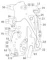
도 4는 본 발명의 일 실시예에 따른 차량용 열관리 유체 모듈에서 고온의 유체 및 저온의 유체의 흐름을 도시한 사시도이다.1 is a perspective view showing the front of a thermal management fluid module for a vehicle according to an embodiment of the present invention.
Figure 2 is a perspective view showing the rear of a thermal management fluid module for a vehicle according to an embodiment of the present invention.
Figure 3 is a perspective view showing a thermal management fluid module for a vehicle according to an embodiment of the present invention.
Figure 4 is a perspective view showing the flow of high-temperature fluid and low-temperature fluid in a thermal management fluid module for a vehicle according to an embodiment of the present invention.
본 발명은 다양한 변환을 가할 수 있고 여러 가지 실시예를 가질 수 있는 바, 특정 실시예들을 도면에 예시하고 상세하게 설명하고자 한다. 그러나, 이는 본 발명을 특정한 실시 형태에 대해 한정하려는 것이 아니며, 본 발명의 사상 및 기술 범위에 포함되는 모든 변환, 균등물 내지 대체물을 포함하는 것으로 이해되어야 한다. 본 발명을 설명함에 있어서 관련된 공지 기술에 대한 구체적인 설명이 본 발명의 요지를 흐릴 수 있다고 판단되는 경우 그 상세한 설명을 생략한다.Since the present invention can be modified in various ways and can have various embodiments, specific embodiments will be illustrated in the drawings and described in detail. However, this is not intended to limit the present invention to specific embodiments, and should be understood to include all transformations, equivalents, and substitutes included in the spirit and technical scope of the present invention. In describing the present invention, if it is determined that a detailed description of related known technologies may obscure the gist of the present invention, the detailed description will be omitted.
제1, 제2 등의 용어는 다양한 구성요소들을 설명하는데 사용될 수 있지만, 상기 구성요소들은 상기 용어들에 의해 한정되어서는 안 된다. 상기 용어들은 하나의 구성요소를 다른 구성요소로부터 구별하는 목적으로만 사용된다.Terms such as first, second, etc. may be used to describe various components, but the components should not be limited by the terms. The above terms are used only for the purpose of distinguishing one component from another.
본 출원에서 사용한 용어는 단지 특정한 실시 예를 설명하기 위해 사용된 것으로, 본 발명을 한정하려는 의도가 아니다. 단수의 표현은 문맥상 명백하게 다르게 뜻하지 않는 한, 복수의 표현을 포함한다. 본 출원에서, "포함한다" 또는 "가지다" 등의 용어는 명세서 상에 기재된 특징, 숫자, 단계, 동작, 구성요소, 부품 또는 이들을 조합한 것이 존재함을 지정하려는 것이지, 하나 또는 그 이상의 다른 특징들이나 숫자, 단계, 동작, 구성요소, 부품 또는 이들을 조합한 것들의 존재 또는 부가 가능성을 미리 배제하지 않는 것으로 이해되어야 한다.The terms used in this application are only used to describe specific embodiments and are not intended to limit the invention. Singular expressions include plural expressions unless the context clearly dictates otherwise. In this application, terms such as "comprise" or "have" are intended to designate the presence of features, numbers, steps, operations, components, parts, or combinations thereof described in the specification, but are not intended to indicate the presence of one or more other features. It should be understood that this does not exclude in advance the possibility of the existence or addition of elements, numbers, steps, operations, components, parts, or combinations thereof.
또한, 명세서 전체에서, "연결된다"라고 할 때, 이는 둘 이상의 구성요소가 직접적으로 연결되는 것만을 의미하는 것이 아니고, 둘 이상의 구성요소가 다른 구성요소를 통하여 간접적으로 연결되는 것, 물리적으로 연결되는 것뿐만 아니라 전기적으로 연결되는 것, 또는 위치나 기능에 따라 상이한 명칭들로 지칭되었으나 일체인 것을 의미할 수 있다.In addition, throughout the specification, when "connected" is used, this does not mean that two or more components are directly connected, but rather that two or more components are indirectly connected through other components, or physically connected. It can mean not only being connected but also being electrically connected, or being integrated although referred to by different names depending on location or function.
이하, 본 발명에 의한 매니폴드 유체 모듈의 일 실시예를 첨부도면을 참조하여 상세히 설명하기로 하며, 첨부 도면을 참조하여 설명함에 있어, 동일하거나 대응하는 구성 요소는 동일한 도면번호를 부여하고 이에 대한 중복되는 설명은 생략하기로 한다.Hereinafter, an embodiment of the manifold fluid module according to the present invention will be described in detail with reference to the accompanying drawings. In the description with reference to the accompanying drawings, identical or corresponding components are assigned the same drawing numbers and Redundant explanations will be omitted.
도 1은 본 발명의 일 실시예에 따른 차량용 열관리 유체 모듈의 전면을 도시한 사시도이고, 도 2는 본 발명의 일 실시예에 따른 차량용 열관리 유체 모듈의 후면을 도시한 사시도이며, 도 3은 본 발명의 일 실시예에 따른 차량용 열관리 유체 모듈을 도시한 사시도이고, 도 4는 본 발명의 일 실시예에 따른 차량용 열관리 유체 모듈에서 고온의 유체 및 저온의 유체의 흐름을 도시한 사시도이다.Figure 1 is a perspective view showing the front of a thermal management fluid module for a vehicle according to an embodiment of the present invention, Figure 2 is a perspective view showing the rear of a thermal management fluid module for a vehicle according to an embodiment of the present invention, and Figure 3 is a perspective view showing the front of the thermal management fluid module for a vehicle according to an embodiment of the present invention. It is a perspective view showing a thermal management fluid module for a vehicle according to an embodiment of the present invention, and Figure 4 is a perspective view showing the flows of high-temperature fluid and low-temperature fluid in the thermal management fluid module for a vehicle according to an embodiment of the present invention.
이에 도시된 바에 따르면, 본 발명의 일 실시예에 따른 차량용 열관리 유체 모듈은 내부에 복수개의 유체 유로가 형성되고, 상기 유체 유로를 이동하는 유체의 온도는 상이한 매니폴드 플레이트(10), 및 상기 매니폴드 플레이트(10)에 결합되되, 상기 유체 유로 중 상대적으로 고온이거나 저온인 유체 유로는 다른 유체 유로와 이격되게 분리 형성되는 열간섭 회피부를 포함할 수 있다.As shown, the thermal management fluid module for a vehicle according to an embodiment of the present invention has a plurality of fluid passages formed inside, and the temperature of the fluid moving through the fluid passages is different from the
매니폴드 플레이트(10)는 대략 내부에 유체 유로가 형성되며 소정의 두께를 가진 플레이트 형상을 가진다. 이와 같이 매니폴드 플레이트(10)에는 열관리 시스템의 열교환 장치인 제1 열교환기(20), 제2 열교환기(60)와, 팽창밸브(30,70), 방향전환밸브(40,50)가 결합되어 모듈화됨으로써 제품 제작 공수가 절감되고 차량 조립라인의 공수도 절감될 수 있다. 또한, 매니폴드 플레이트(10)는 배관, 피팅 및 하우징의 기능을 동시에 수행하므로 원가절감 및 작업성을 향상시킬 수 있다.The
매니폴드 플레이트(10)는 바텀 플레이트(11) 및 탑 플레이트(12)로 구성되는 어셈블리를 포함하며, 브레이징(Brazing), 구조용 접착제(Structural adhesives), 가스켓 등을 이용하여 결합하는 방식으로 제작이 가능하다. 또한, 매니폴드 플레이트(10)의 재료는 제작방식에 따라, 알루미늄, 열가소성 플라스틱(Thermo-plastic), 스테인리스강 등 목적과 기능에 따라 다양하게 적용될 수 있다.The
바텀 플레이트(11)는 판상으로 형성되고, 탑 플레이트(12)는 바텀 플레이트(11)의 일면에 소정의 두께로 돌출되게 결합됨으로써 바텀 플레이트(11)와의 사이에 유체 유로를 형성하게 된다.The
도 2를 참조하면, 매니폴드 플레이트(10)의 후면에는 압축기 또는 내부 응축기에서 토출된 고온 고압의 기상 유체가 유입되는 유체 유입 포트(14)가 구비된다. 또한, 매니폴드 플레이트(10)의 후면에는 유체의 유입 및 배출을 위한 각종 유체 포트가 구비될 수 있다. 본 실시예에서는 제1 유체가 외부 열교환기(80)로 배출되는 외부 열교환기 배출 포트(16)가 구비된다. 또한, 이하에서 설명할 제1 분지 포트(111) 및 제2 분지 포트(121)가 매니폴드 플레이트(10)의 후면에 구비될 수 있다.Referring to FIG. 2, the rear of the
다시 도 1을 참조하면, 매니폴드 플레이트(10)에는 열교환 장치로서 제1 열교환기(20) 및 제2 열교환기(60)가 결합된다. 제1 열교환기(20) 및 제2 열교환기(60)에는 제1 유체 및 제2 유체가 각각 통과하면서 열교환될 수 있다.Referring again to FIG. 1, a
본 실시예에서 제1 열교환기(20)로는 수냉식 응축기, 제2 열교환기(60)로는 칠러가 사용될 수 있다. 수냉식 응축기는 압축기 또는 내부 응축기에서 토출된 고온 고압의 기상 유체(냉매)를 외부 열원과 열교환시켜 고압의 액체로 응축하는 역할을 한다. 칠러는 저온 저압의 유체가 공급되어 냉각수 순환라인(미도시)에서 이동하는 제2 유체(냉각수)와 열교환되는 장치로서, 칠러에서 열교환된 차가운 냉각수는 냉각수 순환라인을 순환하여 배터리와 열교환될 수 있다.In this embodiment, a water-cooled condenser may be used as the
한편, 제1 유체 및 제2 유체는 냉매, 냉각수 등이 적용될 수 있는데, 본 실시예에서는 제1 유체로 냉매, 제2 유체로 냉각수가 적용될 수 있다.Meanwhile, a refrigerant, a coolant, etc. may be used as the first fluid and the second fluid. In this embodiment, a refrigerant may be used as the first fluid and coolant may be used as the second fluid.
제1 열교환기(20)에는 제1 유체가 유입되고 배출되는 제1 유체포트가 구비된다. 제1 유체포트는 제1 열교환기(20)의 상단 및 하단에 각각 구비되는 제1 유입단(21) 및 제1 배출단(22)을 포함한다. 제1 유입단(21)은 제1 팽창밸브(30)를 거친 제1 유체가 유입되는 부분이고, 제1 배출단(22)은 제1 열교환기(20)에서 열교환한 제1 유체가 배출되는 부분이다. 제1 유입단(21) 및 제1 배출단(22)은 제1 열교환기(20)의 상단 및 하단에 각각 홀 형태로 형성될 수 있다.The
이때, 열 간섭을 고려하여, 제1 유입단(21)은 제1 팽창밸브(30)와 가까운 일측에 형성되고, 제1 배출단(22)은 제1 팽창밸브(30)와 먼 타측에 형성될 수 있다. 보다 상세하게는 제1 팽창밸브(30)를 기준으로 제1 유입단(21)은 제1 배출단(22)보다 가깝게 배치될 수 있다. 예컨데, 제1 팽창밸브(30)에서 제1 유입단(21)까지의 거리는 제1 팽창밸브(30)에서 제1 배출단(22)까지의 거리보다 작을 수 있다.At this time, in consideration of thermal interference, the
그리고, 제1 열교환기(20)에는 제2 유체가 유입되고 배출되는 제2 유체포트가 구비된다. 제2 유체포트는 제1 열교환기(20)의 하단 및 상단에 각각 구비되는 제2 유입단(23) 및 제2 배출단(24)을 포함한다. 제2 유입단(23)은 제2 유체가 유입되는 부분이고, 제2 배출단(24)은 제1 유체와 열교환한 제2 유체가 배출되는 부분이다. 제2 유체는 제1 유체와 반대방향(하부->상부)으로 흐르면서 제1 유체와 열교환된다.In addition, the
위에서 설명한 제1 유체포트 및 제2 유체포트는 서로 분리되어 배치되기 때문에 제1 유체 배관 및 제2 유체 배관의 조립성이 향상될 수 있다.Since the first fluid port and the second fluid port described above are disposed separately from each other, assembly of the first fluid pipe and the second fluid pipe can be improved.
제1 팽창밸브(30)는 제1 열교환기(20)로 유입되는 냉매의 팽창여부를 제어하는 역할을 한다. 제1 팽창밸브(30)는 제1 열교환기(20)의 상방에 배치될 수 있으며, 유체 유입 포트(14)를 통해 유입되는 제1 유체를 팽창 또는 통과시킬 수 있다. 제1 팽창밸브(30)를 통해 유입되는 제1 유체는 제1 열교환기(20)를 통과하면서 열교환이 진행되거나 이동하여 외부 열교환기로 이동할 수 있다.The
제1 열교환기(20)의 제1 배출단(22)을 통해 배출된 제1 유체는 제1 방향전환밸브(40)로 유입된다. 제1 방향전환밸브(40)는 제1 열교환기(20)에서 배출되는 제1 유체의 방향을 제어하는 역할을 한다. 제1 방향전환밸브(40)로 유입된 제1 유체는 외부 열교환기(80)로 이동할 수 있다. 이때, 제1 유체는 외부 열교환기 배출 포트(16)를 통해 외부 열교환기(80)와 이동이 가능하다.The first fluid discharged through the
또한, 제1 팽창밸브(30)로 유입된 제1 유체는 제습 모드에서 제2 방향전환밸브(50)로 이동된 후 증발기(82)로 이동할 수 있다.Additionally, the first fluid flowing into the
제2 열교환기(60)는 저온 저압의 제1 유체가 공급되어 냉각수 순환라인(미도시)에서 이동하는 제2 유체(냉각수)와 열교환된다. 제2 열교환기(60)에서 열교환된 차가운 제2 유체는 냉각수 순환라인을 순환하여 배터리와 열교환될 수 있다. 제2 팽창밸브(70)에는 외부 열교환기(80)와 열교환된 제1 유체가 유입되고 제2 팽창밸브(70)에서 팽창된 제1 유체는 제2 열교환기(60)로 유입된다. 제2 열교환기(60)에서 열교환된 제1 유체는 하단을 통해 배출되어 어큐뮬레이터(84)로 유입된다.The
이를 위해 제2 열교환기(60)에는 제1 유체가 유입되고 배출되는 제1 유체포트가 구비된다. 제1 유체포트는 제2 열교환기(60)의 상단 및 하단에 각각 구비되는 제1 유입단(61) 및 제1 배출단(62)을 포함한다. 제1 유입단(61)은 제1 유체가 유입되는 부분이고, 제1 배출단(62)은 제2 열교환기(60)에서 열교환한 제1 유체가 배출되는 부분이다. 제1 유입단(61) 및 제1 배출단(62)은 제2 열교환기(60)의 상단 및 하단에 각각 홀 형태로 형성될 수 있다.For this purpose, the
이때, 열 간섭을 고려하여, 제2 열교환기(60)의 제1 유입단(61)은 제2 팽창밸브(70)와 가까운 일측에 형성되고, 제1 배출단(62)은 제2 팽창밸브(70)와 먼 타측에 형성될 수 있다. 보다 상세하게는 제2 팽창밸브(70)를 기준으로 제1 유입단(61)은 제1 배출단(62)보다 가깝게 배치될 수 있다. 예컨데, 제2 팽창밸브(70)에서 제1 유입단(61)까지의 거리는 제2 팽창밸브(70)에서 제1 배출단(62)까지의 거리보다 작을 수 있다.At this time, in consideration of thermal interference, the
열간섭 회피부는 매니폴드 플레이트(10)에 형성된 유체 유로 중 상대적으로 고온이거나 저온인 유체 유로는 다른 유체 유로와 이격되게 분리 형성할 수 있다. 매니폴드 플레이트(10)에 형성된 유체 유로를 유동하는 유체의 온도가 비슷하다면 매니폴드 플레이트(10) 자체에 유체 유로를 전체적으로 배치할 수 있다. 하지만, 유체의 경로에 따라 상대적으로 고온이거나 저온인 유체가 유동하게 되고 이와 같이 서로 온도 차이가 많을수록 매니폴드 플레이트(10) 내에서 함께 유동하게 되면 서로 간의 열간섭으로 인하여 열관리 성능이 저하될 수 있다.The thermal interference avoidance unit may separate the relatively high or low temperature fluid channels among the fluid channels formed in the
따라서, 본 실시예에서는 유체 유로를 유동하는 유체의 온도가 일정 기준치를 초과하거나 미달하는 유로에 대해서는 매니폴드 플레이트(10) 자체에 형성하지 않고 매니폴드 플레이트(10)와 분리하여 형성하여 서로 간의 열간섭을 피하도록 한 것이다. 이와 같이 유체의 온도가 차이가 있는 유로는 분리하여 배치하면 기존에 배치된 유로와 열간섭이 발생하지 않기 때문에 열관리 성능을 극대화시킬 수 있다.Therefore, in this embodiment, for channels where the temperature of the fluid flowing through the fluid path exceeds or falls below a certain standard value, it is not formed in the
열간섭 회피부는 증발기(82)에서 유출되는 저온의 유체를 어큐뮬레이터(84)로 유동시키기 위한 유체 유로, 및 외부 열교환기(80)에서 유출되는 고온의 유체를 증발기(82)로 유동시키기 위한 유체 유로를 포함할 수 있는 구성이라면 어떠한 것이라도 적용될 수 있다.The thermal interference avoidance unit has a fluid flow path for flowing the low-temperature fluid flowing out of the
열간섭 회피부는 매니폴드 플레이트(10)의 일면에 결합되도록 구성될 수 있다. 이하에서는 열간섭 회피부로서 매니폴드 플레이트(10)의 일면에 결합되는 배관을 일 실시예로 들어 설명하고 있으나, 이에 제한되는 것은 아니고 호스, 별도의 매니폴드형 플레이트 등 다양한 구성으로 통해 구현될 수 있다.The thermal interference avoidance unit may be configured to be coupled to one surface of the
열간섭 회피부는 매니폴드 플레이트(10)의 후면 즉, 탑 플레이트(12)가 결합된 전면의 반대면에 배치될 수 있다. 이는 열간섭 회피부에 포함되는 유체 유로가 탑 플레이트(12)에 형성된 유체 유로와 간섭되는 것을 원천적으로 방지하기 위함이다.The thermal interference avoidance unit may be disposed on the rear side of the
열간섭 회피부는 매니폴드 플레이트(10)의 일면에 결합되는 분지 배관(100)일 수 있다. 분지 배관(100)은 증발기(82)에서 유출되는 저온의 유체를 어큐뮬레이터(84)로 유동시키기 위한 제1 배관(110), 및 외부 열교환기(80)에서 유출되는 고온의 유체를 증발기(82)로 유동시키기 위한 제2 배관(120)을 포함할 수 있다.The thermal interference avoidance unit may be a branch pipe 100 coupled to one surface of the
도 4를 참조하면, 제1 배관(110)은 증발기(82)에서 유출되는 저온의 제1 유체를 어큐뮬레이터(84) 측으로 유동시키기 위해 연장될 수 있다. 증발기(82)에서 유출되는 제1 유체는 저온 상태(10~20℃)이므로 매니폴드 플레이트(10) 상에서 유동을 하게 되면 고온의 유체 유로와 열간섭이 발생할 수 있어 별도의 제1 배관(110)을 따라 유동되도록 구성한 것이다. 제1 배관(110)은 매니폴드 플레이트(10)의 일면에 결합된 제1 분지 포트(111)에 연결될 수 있다. 여기에서 제1 분지 포트(111)로는 플랜지 등이 적용될 수 있다.Referring to FIG. 4, the
이와 같이 제1 배관(110)을 따라 저온의 제1 유체가 유동하면 매니폴드 플레이트(10)를 경유하지 않고 바로 어큐뮬레이터(84) 또는 압축기로 연결되기 때문에 고온의 유체 유로와의 열간섭을 회피할 수 있다.In this way, when the low-temperature first fluid flows along the
제2 배관(120)은 외부 열교환기(80)에서 유출되는 고온의 제1 유체를 증발기(82) 측으로 유동시키기 위해 연장될 수 있다. 외부 열교환기(80)에서 유출되는 제1 유체는 고온 상태(60~70℃)이므로 매니폴드 플레이트(10) 상에서 유동을 하게 되면 상대적으로 저온인 유체 유로와 열간섭이 발생할 수 있어 별도의 제2 배관(120)을 따라 유동되도록 구성한 것이다. 제2 배관(120)은 매니폴드 플레이트(10)의 일면에 결합된 제2 분지 포트(121)에 연결될 수 있다. 여기에서 제2 분지 포트(121)로는 플랜지 등이 적용될 수 있다. 이상에서는 분지 배관(100)은 내부에 단순히 유로의 전환을 위한 유체 유로를 가진 분지 포트(111,121)와 연결되는 것으로 설명하였으나, 이에 제한되는 것은 아니고 내부에 유체 유로를 가진 유로 전환 밸브와 연결되는 형태로 구성될 수도 있다.The second pipe 120 may be extended to flow the high-temperature first fluid flowing out of the
이와 같이 제2 배관(120)을 따라 고온의 제1 유체가 유동하면 매니폴드 플레이트(10)를 경유하지 않고 바로 증발기(82)로 연결되기 때문에 상대적으로 저온인 유체 유로와의 열간섭을 회피할 수 있다.In this way, when the high-temperature first fluid flows along the second pipe 120, it is directly connected to the
한편, 제2 배관(120)은 외부 열교환기(80)와 상기 제2 분지 포트(121)를 연결하는 제1 연결부(122), 상기 제2 분지 포트(121)와 상기 제1 배관(110)의 일측을 연결하는 제2 연결부(124), 및 상기 제1 배관(110)의 일측과 상기 증발기(82)를 연결하는 제3 연결부(126)를 포함할 수 있다. 이상에 기재된 제2 배관(120)의 연결 구조는 일 예로 제시한 것에 불과하고 이에 제한되는 것은 아니다.Meanwhile, the second pipe 120 includes a
또한, 제1 배관(110)의 직경은 제2 배관(120)의 직경보다 상대적으로 클 수 있다. 이는 상대적으로 제1 배관을 유동하는 저온 저압의 제1 유체는 단면적 크기 등 유동 저항에 민감하기 때문에 상대적으로 유동 단면적을 크게 구성한 것이다.Additionally, the diameter of the
한편, 본 발명의 다른 실시예에 따른 차량용 열관리 유체 모듈은 내부에 복수개의 유체 유로가 형성되는 매니폴드 플레이트(10), 및 상기 매니폴드 플레이트(10)에 결합되되, 유체 순환 모드에 따라서 상기 매니폴드 플레이트(10) 내부의 상기 유체 유로로 유입되거나 상기 유체 유로로 유입되지 않고 바이패스 하도록 형성되는 분지 배관(100)을 포함할 수 있다. 본 실시예에서는 분지 배관(100)이 유체의 유동을 매니폴드 플레이트(10)의 외부로만 유도하지 않고 매니폴드 플레이트(10) 내부의 유체 유로로 유입되어 유동할 수 있다.Meanwhile, a thermal management fluid module for a vehicle according to another embodiment of the present invention includes a
매니폴드 플레이트(10)의 일면에는 열교환기 및 각종 밸브가 결합되고, 타면에는 분지 배관(100)이 연결되는 분지 포트(111,121)가 구비된다. 여기에서 제2 분지 포트(121)를 예로 들어 설명하면 제2 분지 포트(121)는 유체가 유입되는 제1 유입구(121a), 매니폴드 플레이트(10)와 연결되는 제1 유출구(121b) 및 분지 배관(100)과 연결되는 제2 유출구(121c)를 포함할 수 있다(도 2 및 도 3 참조).유체 순환 모드에 따라 제1 유입구(121a)를 통해 유입된 유체는 제1 유출구(121b)를 통해 매니폴드 플레이트(10)의 유체 유로로 유입되어 열교환기 및 밸브로 유동할 수 있다. 즉, 제1 유입구(121a)를 통해 유입된 유체가 매니폴드 플레이트(10)의 외부에서 유동하지 않고 매니폴드 플레이트(10)의 내부로 유입되어 유동할 수 있는 것이다.보다 구체적으로 유체 순환 모드는 난방 모드와 냉방 모드를 포함하고, 난방 모드 시에는 유체가 제1 유출구(121b)를 통해 매니폴드 플레이트(10)의 유체 유로로 유동하고, 냉방 모드 시에는 유체가 매니폴드 플레이트(10)를 바이패스하여 유동하는 것이다.A heat exchanger and various valves are coupled to one side of the
이는 난방 모드 시에는 매니폴드 플레이트(10) 내의 유체 유로 간의 온도차가 상대적으로 작기 때문에 유체가 매니폴드 플레이트(10) 내를 유동하여도 열간섭이 적으나, 냉방 모드 시에는 매니폴드 플레이트(10)의 내의 유체 유로 간의 온도차가 상대적으로 크기 때문에 유체가 매니폴드 플레이트(10)를 바이패스하도록 하여 열간섭을 방지하도록 한 것이다.This is because the temperature difference between the fluid passages within the
상기에서는 본 발명의 특정의 실시예를 참조하여 설명하였지만, 해당 기술 분야에서 통상의 지식을 가진 자라면 하기의 특허 청구의 범위에 기재된 본 발명의 사상 및 영역으로부터 벗어나지 않는 범위 내에서 본 발명을 다양하게 수정 및 변경시킬 수 있음을 이해할 수 있을 것이다.Although the present invention has been described above with reference to specific embodiments, those skilled in the art will understand the present invention in various ways without departing from the spirit and scope of the present invention as set forth in the claims below. You will understand that it can be modified and changed.
10: 매니폴드 플레이트11: 바텀 플레이트
12: 탑 플레이트14: 유체 유입 포트
16: 외부 열교환기 배출 포트20: 제1 열교환기
21: 제1 유입단22: 제1 배출단
23: 제2 유입단24: 제2 배출단
30: 제1 팽창밸브40: 제1 방향전환밸브
50: 제2 방향전환밸브60: 제2 열교환기
61: 제1 유입단62: 제1 배출단
70: 제2 팽창밸브80: 외부 열교환기
82: 증발기84: 어큐뮬레이터
100: 분지 배관110: 제1 배관
111: 제1 분지 포트120: 제2 배관
121: 제2 분지 포트121a: 제1 유입구
121b: 제1 유출구121c: 제2 배출구
122: 제1 연결부124: 제2 연결부
126: 제3 연결부10: Manifold plate 11: Bottom plate
12: Top plate 14: Fluid inlet port
16: External heat exchanger discharge port 20: First heat exchanger
21: first inlet stage 22: first outlet stage
23: second inlet end 24: second outlet end
30: first expansion valve 40: first direction change valve
50: second direction change valve 60: second heat exchanger
61: first inlet stage 62: first outlet stage
70: second expansion valve 80: external heat exchanger
82: evaporator 84: accumulator
100: branch pipe 110: first pipe
111: first branch port 120: second pipe
121:
121b:
122: first connection portion 124: second connection portion
126: third connection
Claims (14)
Translated fromKorean내부에 복수개의 유체 유로가 형성되는 매니폴드 플레이트; 및
상기 매니폴드 플레이트에 결합되되, 상기 유체 유로 중 상대적으로 고온이거나 저온인 유체 유로는 다른 유체 유로와 이격되게 분리 형성되는 열간섭 회피부를 포함하는 차량용 열관리 유체 모듈.In a thermal management fluid module for a vehicle that uses a circulating fluid such as refrigerant or coolant,
A manifold plate with a plurality of fluid passages formed therein; and
A thermal management fluid module for a vehicle including a thermal interference avoidance unit coupled to the manifold plate, wherein a relatively high or low temperature fluid passage among the fluid passages is separated from other fluid passages.
상기 유체는 냉매로 압축기, 응축기, 팽창밸브, 증발기 및 어큐뮬레이터를 순환하는 차량용 열관리 유체 모듈.According to paragraph 1,
The fluid is a refrigerant and is a thermal management fluid module for vehicles that circulates through a compressor, condenser, expansion valve, evaporator, and accumulator.
상기 매니폴드 플레이트에서 이격되게 분리 형성되는 유체 유로는,
증발기에서 유출되는 저온의 유체를 어큐뮬레이터로 유동시키기 위한 유체 유로; 및 외부 열교환기에서 유출되는 고온의 유체를 상기 증발기로 유동시키기 위한 유체 유로를 포함하는 차량용 열관리 유체 모듈.According to paragraph 1,
The fluid flow path is formed separately from the manifold plate,
a fluid flow path for flowing the low-temperature fluid flowing out of the evaporator to the accumulator; and a fluid flow path for flowing high-temperature fluid flowing out of an external heat exchanger to the evaporator.
상기 열간섭 회피부는 상기 매니폴드 플레이트의 일면에 결합되고, 내부에 유체 유로가 형성되는 분지 배관인 차량용 열관리 유체 모듈.According to paragraph 1,
The thermal management fluid module for a vehicle is a branch pipe in which the thermal interference avoidance unit is coupled to one surface of the manifold plate and a fluid flow path is formed therein.
상기 분지 배관은,
증발기에서 유출되는 저온의 유체를 어큐뮬레이터로 유동시키기 위한 제1 배관; 및
외부 열교환기에서 유출되는 고온의 유체를 증발기로 유동시키기 위한 제2 배관을 포함하는 차량용 열관리 유체 모듈.According to paragraph 4,
The branch pipe is,
a first pipe for flowing low-temperature fluid flowing out of the evaporator to the accumulator; and
A thermal management fluid module for a vehicle including a second pipe for flowing high-temperature fluid flowing out of an external heat exchanger to an evaporator.
상기 매니폴드 플레이트의 일면에는 상기 제1 배관 및 제2 배관의 연결을 위한 제1 분지 포트 및 제2 분지 포트가 결합되는 차량용 열관리 유체 모듈.According to clause 5,
A thermal management fluid module for a vehicle in which a first branch port and a second branch port for connecting the first pipe and the second pipe are coupled to one surface of the manifold plate.
상기 제2 배관은,
상기 외부 열교환기와 상기 제2 분지 포트를 연결하는 제1 연결부;
상기 제2 분지 포트와 상기 제1 배관의 일측을 연결하는 제2 연결부; 및
상기 제1 배관의 일측과 상기 증발기를 연결하는 제3 연결부를 포함하는 차량용 열관리 유체 모듈.According to clause 6,
The second pipe is,
A first connection portion connecting the external heat exchanger and the second branch port;
a second connection portion connecting the second branch port and one side of the first pipe; and
A thermal management fluid module for a vehicle including a third connection portion connecting one side of the first pipe and the evaporator.
상기 제1 배관의 직경은 상기 제2 배관의 직경보다 상대적으로 큰 차량용 열관리 유체 모듈.According to clause 5,
A thermal management fluid module for a vehicle in which the diameter of the first pipe is relatively larger than the diameter of the second pipe.
상기 매니폴드 플레이트는 바텀 플레이트 및 상기 바텀 플레이트의 일면에 돌출되게 결합되어 유체 유로를 형성하는 탑 플레이트를 포함하고,
상기 바텀 플레이트의 타면에는 상기 분지 배관이 연결되는 차량용 열관리 유체 모듈.According to clause 4,
The manifold plate includes a bottom plate and a top plate protruding from one surface of the bottom plate to form a fluid flow path,
A thermal management fluid module for a vehicle in which the branch pipe is connected to the other side of the bottom plate.
내부에 복수개의 유체 유로가 형성되는 매니폴드 플레이트; 및
상기 매니폴드 플레이트에 결합되되, 유체 순환 모드에 따라서 상기 매니폴드 플레이트 내부의 상기 유체 유로로 유입되거나 상기 유체 유로로 유입되지 않고 바이패스 하도록 형성되는 분지 배관을 포함하는 차량용 열관리 유체 모듈.In a thermal management fluid module for a vehicle that uses a circulating fluid such as refrigerant or coolant,
A manifold plate with a plurality of fluid channels formed therein; and
A thermal management fluid module for a vehicle including a branch pipe that is coupled to the manifold plate and is formed to flow into the fluid flow path inside the manifold plate or bypass the fluid flow path without flowing into the fluid flow path depending on the fluid circulation mode.
상기 매니폴드 플레이트의 일면에는 열교환기 및 밸브가 결합되고, 타면에는 상기 분지 배관이 연결되는 분지 포트가 구비되는 차량용 열관리 유체 모듈.According to clause 10,
A heat management fluid module for a vehicle, wherein a heat exchanger and a valve are coupled to one side of the manifold plate, and a branch port to which the branch pipe is connected is provided on the other side.
상기 분지 포트는,
유체가 유입되는 제1 유입구;
상기 매니폴드 플레이트와 연결되는 제1 유출구; 및
상기 분지 배관과 연결되는 제2 유출구를 포함하는 차량용 열관리 유체 모듈.According to clause 11,
The branch port is,
a first inlet through which fluid flows;
a first outlet connected to the manifold plate; and
A thermal management fluid module for a vehicle including a second outlet connected to the branch pipe.
상기 유체 순환 모드에 따라 상기 제1 유입구를 통해 유입된 유체는 상기 제1 유출구를 통해 상기 매니폴드 플레이트의 유체 유로로 유입되어 상기 열교환기 및 밸브로 유동하는 차량용 열관리 유체 모듈.According to clause 12,
A thermal management fluid module for a vehicle in which fluid flowing in through the first inlet according to the fluid circulation mode flows into the fluid passage of the manifold plate through the first outlet and flows to the heat exchanger and valve.
상기 유체 순환 모드는 난방 모드와 냉방 모드를 포함하고,
상기 난방 모드 시에는 유체가 상기 매니폴드 플레이트의 유체 유로로 유동하고, 상기 냉방 모드 시에는 유체가 상기 매니폴드 플레이트를 바이패스하여 유동하는 차량용 열관리 유체 모듈.According to clause 13,
The fluid circulation mode includes a heating mode and a cooling mode,
A thermal management fluid module for a vehicle in which fluid flows into a fluid passage of the manifold plate in the heating mode, and fluid flows by bypassing the manifold plate in the cooling mode.
Priority Applications (4)
| Application Number | Priority Date | Filing Date | Title |
|---|---|---|---|
| KR1020220138007AKR20240057623A (en) | 2022-10-25 | 2022-10-25 | Fluid module for automotive thermal management |
| US18/381,281US20240227509A9 (en) | 2022-10-25 | 2023-10-18 | Thermal management fluid module for vehicle |
| CN202311379938.4ACN117922229A (en) | 2022-10-25 | 2023-10-23 | Thermal management fluid module for a vehicle |
| DE102023129259.5ADE102023129259A1 (en) | 2022-10-25 | 2023-10-24 | VEHICLE HEAT MANAGEMENT FLUID MODULE |
Applications Claiming Priority (1)
| Application Number | Priority Date | Filing Date | Title |
|---|---|---|---|
| KR1020220138007AKR20240057623A (en) | 2022-10-25 | 2022-10-25 | Fluid module for automotive thermal management |
Publications (1)
| Publication Number | Publication Date |
|---|---|
| KR20240057623Atrue KR20240057623A (en) | 2024-05-03 |
Family
ID=90573121
Family Applications (1)
| Application Number | Title | Priority Date | Filing Date |
|---|---|---|---|
| KR1020220138007APendingKR20240057623A (en) | 2022-10-25 | 2022-10-25 | Fluid module for automotive thermal management |
Country Status (4)
| Country | Link |
|---|---|
| US (1) | US20240227509A9 (en) |
| KR (1) | KR20240057623A (en) |
| CN (1) | CN117922229A (en) |
| DE (1) | DE102023129259A1 (en) |
Family Cites Families (1)
| Publication number | Priority date | Publication date | Assignee | Title |
|---|---|---|---|---|
| KR20220138007A (en) | 2017-05-16 | 2022-10-12 | 애플 인크. | Devices, methods, and graphical user interfaces for navigating between user interfaces and interacting with control objects |
- 2022
- 2022-10-25KRKR1020220138007Apatent/KR20240057623A/enactivePending
- 2023
- 2023-10-18USUS18/381,281patent/US20240227509A9/enactivePending
- 2023-10-23CNCN202311379938.4Apatent/CN117922229A/enactivePending
- 2023-10-24DEDE102023129259.5Apatent/DE102023129259A1/enactivePending
Also Published As
| Publication number | Publication date |
|---|---|
| US20240227509A9 (en) | 2024-07-11 |
| CN117922229A (en) | 2024-04-26 |
| US20240131903A1 (en) | 2024-04-25 |
| DE102023129259A1 (en) | 2024-04-25 |
Similar Documents
| Publication | Publication Date | Title |
|---|---|---|
| US20250058605A1 (en) | Manifold fluid module | |
| US20250242666A1 (en) | Manifold fluid module | |
| CN119137003A (en) | Manifold Fluid Modules | |
| KR20240010252A (en) | Manifold fluid module | |
| KR20240010250A (en) | Manifold fluid module integrated gas-liquid separator | |
| KR20240057623A (en) | Fluid module for automotive thermal management | |
| KR20230163106A (en) | Manifold fluid module | |
| KR20230163105A (en) | Manifold fluid module | |
| US20250276561A1 (en) | Automotive thermal management fluid module | |
| KR20240174334A (en) | Fluid module for automotive thermal management | |
| KR20240155786A (en) | Fluid module for automotive thermal management | |
| KR20240155784A (en) | Fluid module for automotive thermal management | |
| KR20240085544A (en) | Manifold fluid module | |
| KR20240099605A (en) | Fluid module for automotive thermal management | |
| US20240190203A1 (en) | Thermal management fluid module for vehicle | |
| KR20240155614A (en) | Fluid module for automotive thermal management | |
| KR20240141406A (en) | Fluid module for automotive thermal management | |
| US20250102230A1 (en) | Manifold fluid module | |
| KR20240155602A (en) | Fluid module for automotive thermal management | |
| KR20240155600A (en) | Fluid module for automotive thermal management | |
| KR20240138312A (en) | Fluid module for automotive thermal management | |
| KR20230108064A (en) | Manifold refrigerant module | |
| KR20240149053A (en) | Manifold fluid module | |
| US20250187404A1 (en) | Heat pump system for a vehicle | |
| KR20240142076A (en) | Refrigerant module assembly |
Legal Events
| Date | Code | Title | Description |
|---|---|---|---|
| PA0109 | Patent application | Patent event code:PA01091R01D Comment text:Patent Application Patent event date:20221025 | |
| PG1501 | Laying open of application | ||
| A201 | Request for examination | ||
| PA0201 | Request for examination | Patent event code:PA02012R01D Patent event date:20250120 Comment text:Request for Examination of Application |