KR20240054783A - Apparatus for managing battery and operating method of the same - Google Patents
Apparatus for managing battery and operating method of the sameDownload PDFInfo
- Publication number
- KR20240054783A KR20240054783AKR1020220135174AKR20220135174AKR20240054783AKR 20240054783 AKR20240054783 AKR 20240054783AKR 1020220135174 AKR1020220135174 AKR 1020220135174AKR 20220135174 AKR20220135174 AKR 20220135174AKR 20240054783 AKR20240054783 AKR 20240054783A
- Authority
- KR
- South Korea
- Prior art keywords
- battery
- capacitor
- voltage
- precharging
- time
- Prior art date
- Legal status (The legal status is an assumption and is not a legal conclusion. Google has not performed a legal analysis and makes no representation as to the accuracy of the status listed.)
- Pending
Links
Images


Classifications
- G—PHYSICS
- G01—MEASURING; TESTING
- G01R—MEASURING ELECTRIC VARIABLES; MEASURING MAGNETIC VARIABLES
- G01R31/00—Arrangements for testing electric properties; Arrangements for locating electric faults; Arrangements for electrical testing characterised by what is being tested not provided for elsewhere
- G01R31/36—Arrangements for testing, measuring or monitoring the electrical condition of accumulators or electric batteries, e.g. capacity or state of charge [SoC]
- G01R31/389—Measuring internal impedance, internal conductance or related variables
- H—ELECTRICITY
- H01—ELECTRIC ELEMENTS
- H01M—PROCESSES OR MEANS, e.g. BATTERIES, FOR THE DIRECT CONVERSION OF CHEMICAL ENERGY INTO ELECTRICAL ENERGY
- H01M10/00—Secondary cells; Manufacture thereof
- H01M10/42—Methods or arrangements for servicing or maintenance of secondary cells or secondary half-cells
- H01M10/48—Accumulators combined with arrangements for measuring, testing or indicating the condition of cells, e.g. the level or density of the electrolyte
- G—PHYSICS
- G01—MEASURING; TESTING
- G01N—INVESTIGATING OR ANALYSING MATERIALS BY DETERMINING THEIR CHEMICAL OR PHYSICAL PROPERTIES
- G01N27/00—Investigating or analysing materials by the use of electric, electrochemical, or magnetic means
- G01N27/02—Investigating or analysing materials by the use of electric, electrochemical, or magnetic means by investigating impedance
- G01N27/026—Dielectric impedance spectroscopy
- G—PHYSICS
- G01—MEASURING; TESTING
- G01R—MEASURING ELECTRIC VARIABLES; MEASURING MAGNETIC VARIABLES
- G01R19/00—Arrangements for measuring currents or voltages or for indicating presence or sign thereof
- G01R19/165—Indicating that current or voltage is either above or below a predetermined value or within or outside a predetermined range of values
- G01R19/16533—Indicating that current or voltage is either above or below a predetermined value or within or outside a predetermined range of values characterised by the application
- G01R19/16538—Indicating that current or voltage is either above or below a predetermined value or within or outside a predetermined range of values characterised by the application in AC or DC supplies
- G01R19/16542—Indicating that current or voltage is either above or below a predetermined value or within or outside a predetermined range of values characterised by the application in AC or DC supplies for batteries
- G—PHYSICS
- G01—MEASURING; TESTING
- G01R—MEASURING ELECTRIC VARIABLES; MEASURING MAGNETIC VARIABLES
- G01R19/00—Arrangements for measuring currents or voltages or for indicating presence or sign thereof
- G01R19/165—Indicating that current or voltage is either above or below a predetermined value or within or outside a predetermined range of values
- G01R19/16566—Circuits and arrangements for comparing voltage or current with one or several thresholds and for indicating the result not covered by subgroups G01R19/16504, G01R19/16528, G01R19/16533
- G01R19/16571—Circuits and arrangements for comparing voltage or current with one or several thresholds and for indicating the result not covered by subgroups G01R19/16504, G01R19/16528, G01R19/16533 comparing AC or DC current with one threshold, e.g. load current, over-current, surge current or fault current
- G—PHYSICS
- G01—MEASURING; TESTING
- G01R—MEASURING ELECTRIC VARIABLES; MEASURING MAGNETIC VARIABLES
- G01R31/00—Arrangements for testing electric properties; Arrangements for locating electric faults; Arrangements for electrical testing characterised by what is being tested not provided for elsewhere
- G01R31/36—Arrangements for testing, measuring or monitoring the electrical condition of accumulators or electric batteries, e.g. capacity or state of charge [SoC]
- G01R31/367—Software therefor, e.g. for battery testing using modelling or look-up tables
- G—PHYSICS
- G01—MEASURING; TESTING
- G01R—MEASURING ELECTRIC VARIABLES; MEASURING MAGNETIC VARIABLES
- G01R31/00—Arrangements for testing electric properties; Arrangements for locating electric faults; Arrangements for electrical testing characterised by what is being tested not provided for elsewhere
- G01R31/36—Arrangements for testing, measuring or monitoring the electrical condition of accumulators or electric batteries, e.g. capacity or state of charge [SoC]
- G01R31/396—Acquisition or processing of data for testing or for monitoring individual cells or groups of cells within a battery
- H—ELECTRICITY
- H01—ELECTRIC ELEMENTS
- H01M—PROCESSES OR MEANS, e.g. BATTERIES, FOR THE DIRECT CONVERSION OF CHEMICAL ENERGY INTO ELECTRICAL ENERGY
- H01M10/00—Secondary cells; Manufacture thereof
- H01M10/05—Accumulators with non-aqueous electrolyte
- H01M10/052—Li-accumulators
- H—ELECTRICITY
- H01—ELECTRIC ELEMENTS
- H01M—PROCESSES OR MEANS, e.g. BATTERIES, FOR THE DIRECT CONVERSION OF CHEMICAL ENERGY INTO ELECTRICAL ENERGY
- H01M10/00—Secondary cells; Manufacture thereof
- H01M10/42—Methods or arrangements for servicing or maintenance of secondary cells or secondary half-cells
- H01M10/425—Structural combination with electronic components, e.g. electronic circuits integrated to the outside of the casing
- H01M2010/4271—Battery management systems including electronic circuits, e.g. control of current or voltage to keep battery in healthy state, cell balancing
Landscapes
- Physics & Mathematics (AREA)
- General Physics & Mathematics (AREA)
- Engineering & Computer Science (AREA)
- Chemical & Material Sciences (AREA)
- Chemical Kinetics & Catalysis (AREA)
- Electrochemistry (AREA)
- Manufacturing & Machinery (AREA)
- General Chemical & Material Sciences (AREA)
- Power Engineering (AREA)
- Life Sciences & Earth Sciences (AREA)
- Health & Medical Sciences (AREA)
- Analytical Chemistry (AREA)
- Biochemistry (AREA)
- General Health & Medical Sciences (AREA)
- Spectroscopy & Molecular Physics (AREA)
- Immunology (AREA)
- Pathology (AREA)
- Microelectronics & Electronic Packaging (AREA)
- Secondary Cells (AREA)
- Charge And Discharge Circuits For Batteries Or The Like (AREA)
Abstract
Description
Translated fromKorean본 문서에 개시된 실시예들은 배터리 관리 장치 및 그것의 동작 방법에 관한 것이다.Embodiments disclosed herein relate to a battery management device and method of operating the same.
최근 이차 전지에 대한 연구 개발이 활발히 이루어지고 있다. 이차 전지는 충방전이 가능한 전지로서, 종래의 Ni/Cd 배터리, Ni/MH 배터리 등과 최근의 리튬 이온 배터리를 모두 포함하는 의미이다. 이차 전지 중 리튬 이온 배터리는 종래의 Ni/Cd 배터리, Ni/MH 배터리 등에 비하여 에너지 밀도가 훨씬 높다는 장점이 있다. 또한, 리튬 이온 배터리는 소형, 경량으로 제작할 수 있어서 이동 기기의 전원으로 사용되며, 최근에는 전기 자동차의 전원으로 사용 범위가 확장되어 차세대 에너지 저장 매체로 주목을 받고 있다.Recently, research and development on secondary batteries has been actively conducted. Secondary batteries are batteries that can be charged and discharged, and include both conventional Ni/Cd batteries, Ni/MH batteries, and recent lithium-ion batteries. Among secondary batteries, lithium-ion batteries have the advantage of having much higher energy density than conventional Ni/Cd batteries, Ni/MH batteries, etc. In addition, lithium-ion batteries can be made small and lightweight, so they are used as a power source for mobile devices. Recently, their range of use has expanded to a power source for electric vehicles, and they are attracting attention as a next-generation energy storage medium.
이러한 리튬 이온 배터리의 임피던스를 측정하기 위해서 위해 전기 화학 임피던스 분광법(Electrochemical Impedance Spectroscopy)을 사용할 수 있다. 전기 화학 임피던스 분광법은 배터리의 전극에서 화학 반응을 일으킬 때 전기 전달을 방해하는 요소인 임피던스를 정확하게 산출할 수 있다. 임피던스를 측정하는 한 방법으로 정밀한 션트(Shunt) 저항을 배터리와 직렬로 연결한 후, 교류 전류를 발생시켜 션트 저항 양단의 전압을 측정하고, 배터리 양단의 전압을 측정하여 배터리의 임피던스를 측정할 수 있다. 배터리 양단의 전압을 측정할 때, +쪽과 -쪽을 일정 DC 전압으로 클램핑(Clamping) 해준 후 전압을 측정하기 위해 프리차징(Pre-Charging) 커패시터를 연결할 수 있다. 그런데, 종래의 전기 화학 임피던스 분광법은 배터리에 연결된 프리차징 커패시터들의 전압 값을 모니터링하지 않고 일정 시간의 경과 여부에 기초하여 임피던스를 측정하여 임피던스 값의 정확도가 떨어지는 문제가 있다.Electrochemical Impedance Spectroscopy can be used to measure the impedance of such lithium ion batteries. Electrochemical impedance spectroscopy can accurately calculate impedance, a factor that interferes with electrical transmission when a chemical reaction occurs at the electrodes of a battery. One way to measure impedance is to connect a precise shunt resistor in series with the battery, generate an alternating current, measure the voltage across the shunt resistor, and measure the voltage across both ends of the battery to measure the impedance of the battery. there is. When measuring the voltage at both ends of a battery, you can clamp the + and - sides to a certain DC voltage and then connect a pre-charging capacitor to measure the voltage. However, the conventional electrochemical impedance spectroscopy measures impedance based on the elapse of a certain period of time without monitoring the voltage values of precharging capacitors connected to the battery, and thus has a problem in that the accuracy of the impedance value is low.
본 문서에 개시된 실시예들의 일 목적은 배터리에 연결된 커패시터들의 전압값을 모니터링하여 전기 화학 임피던스 분광법으로 측정한 배터리의 임피던스 값의 정확도를 개선할 수 있는 배터리 관리 장치 및 그것의 동작 방법을 제공하는 데 있다.One purpose of the embodiments disclosed in this document is to provide a battery management device and a method of operating the same that can improve the accuracy of the impedance value of the battery measured by electrochemical impedance spectroscopy by monitoring the voltage value of the capacitors connected to the battery. there is.
본 문서에 개시된 실시예들의 기술적 과제들은 이상에서 언급한 기술적 과제들로 제한되지 않으며, 언급되지 않은 또 다른 기술적 과제들은 아래의 기재들로부터 당업자에게 명확하게 이해될 수 있을 것이다.The technical problems of the embodiments disclosed in this document are not limited to the technical problems mentioned above, and other technical problems not mentioned will be clearly understood by those skilled in the art from the description below.
본 문서에 개시된 일 실시예에 따른 배터리 관리 장치는 적어도 하나의 배터리와 각각 연결되는 적어도 하나의 커패시터 및 상기 적어도 하나의 커패시터에 전류를 인가하여 프리차징하고, 상기 적어도 하나의 커패시터 각각의 전압을 측정하고, 상기 적어도 하나의 커패시터의 전압이 임계 범위 이내인지 여부에 기초하여 상기 적어도 하나의 배터리의 임피던스 측정을 제어하는 컨트롤러를 포함할 수 있다.A battery management device according to an embodiment disclosed in this document precharges by applying current to at least one capacitor each connected to at least one battery and the at least one capacitor, and measures the voltage of each of the at least one capacitor. and a controller that controls impedance measurement of the at least one battery based on whether the voltage of the at least one capacitor is within a threshold range.
일 실시예에서, 상기 배터리의 임피던스를 측정하는 적어도 하나의 측정부를 더 포함하고, 상기 적어도 하나의 측정부는 상기 컨트롤러의 제어 신호에 기초하여 상기 배터리의 임피던스를 측정하고, 상기 컨트롤러는 상기 커패시터 각각의 전압이 임계 범위 이내인 경우, 상기 배터리의 임피던스를 측정하는 제어 신호를 생성하여 상기 적어도 하나의 측정부에 전달할 수 있다.In one embodiment, it further includes at least one measuring unit that measures the impedance of the battery, wherein the at least one measuring unit measures the impedance of the battery based on a control signal from the controller, and the controller measures each of the capacitors. If the voltage is within the critical range, a control signal for measuring the impedance of the battery may be generated and transmitted to the at least one measurement unit.
일 실시예에서, 상기 컨트롤러는 상기 커패시터 각각의 전압이 임계 범위 이외인 경우, 상기 적어도 하나의 커패시터를 프리차징한 프리차징 시간의 임계 시간 이상 여부를 판단할 수 있다.In one embodiment, when the voltage of each of the capacitors is outside the threshold range, the controller may determine whether the precharging time for precharging the at least one capacitor is greater than or equal to a threshold time.
일 실시예에서, 상기 컨트롤러는 상기 커패시터 각각의 전압이 임계 범위 이외인 경우, 상기 커패시터를 프리차징한 프리차징 시간의 임계 시간 이상 여부를 판단할 수 있다.In one embodiment, when the voltage of each capacitor is outside the threshold range, the controller may determine whether the precharging time for precharging the capacitor is longer than or equal to a threshold time.
일 실시예에서, 상기 컨트롤러는 상기 프리차징 시간이 상기 임계 시간 이상인 경우, 상기 커패시터 각각의 전압의 임계 범위 이내인지 여부를 재판단할 수 있다.In one embodiment, if the precharging time is greater than or equal to the threshold time, the controller may re-determine whether the voltage of each capacitor is within a threshold range.
일 실시예에서, 상기 컨트롤러는 상기 커패시터 각각의 전압의 임계 범위 이내인지 여부를 임계 횟수까지 재판단한 경우, 상기 배터리의 이상 신호를 생성할 수 있다.In one embodiment, the controller may generate an abnormal signal of the battery when it re-determines whether the voltage of each capacitor is within a threshold range up to a threshold number of times.
일 실시예에서, 상기 컨트롤러는 상기 프리차징 시간이 상기 임계 시간 미만인 경우, 상기 커패시터를 프리차징할 수 있다.In one embodiment, the controller may precharge the capacitor when the precharging time is less than the threshold time.
본 문서에 개시된 일 실시예에 따른 배터리 관리 장치의 동작 방법은 배터리와 연결되는 커패시터에 전류를 인가하여 상기 커패시터를 프리차징(Pre- Charging)하는 단계, 상기 커패시터 각각의 전압을 측정하는 단계 및 상기 커패시터 각각의 전압의 임계 범위 이내인지 여부에 기초하여 상기 배터리의 임피던스를 측정하는 단계를 포함할 수 있다.A method of operating a battery management device according to an embodiment disclosed in this document includes the steps of applying current to a capacitor connected to a battery to pre-charge the capacitor, measuring the voltage of each of the capacitors, and It may include measuring the impedance of the battery based on whether the voltage of each capacitor is within a critical range.
일 실시예에서, 상기 커패시터 각각의 전압의 임계 범위 이내인지 여부에 기초하여 상기 배터리의 임피던스를 측정하는 단계는 상기 커패시터 각각의 전압이 임계 범위 이내인 경우, 상기 배터리의 임피던스를 측정하는 제어 신호를 생성하여 상기 적어도 하나의 커패시터에 전달할 수 있다.In one embodiment, the step of measuring the impedance of the battery based on whether the voltage of each of the capacitors is within the threshold range includes sending a control signal to measure the impedance of the battery when the voltage of each of the capacitors is within the threshold range. It can be generated and delivered to the at least one capacitor.
일 실시예에서, 상기 커패시터 각각의 전압의 임계 범위 이내인지 여부에 기초하여 상기 배터리의 임피던스를 측정하는 단계는 상기 커패시터 각각의 전압이 임계 범위 이외인 경우, 상기 커패시터를 프리차징한 프리차징 시간의 임계 시간 이상 여부를 판단할 수 있다.In one embodiment, the step of measuring the impedance of the battery based on whether the voltage of each of the capacitors is within the threshold range is determined by measuring the impedance of the battery when the voltage of each capacitor is outside the threshold range of the precharging time for precharging the capacitor. It can be determined whether the critical time is exceeded.
일 실시예에서, 상기 커패시터를 프리차징한 프리차징 시간의 임계 시간 이상 여부를 판단하는 단계를 더 포함할 수 있다.In one embodiment, the method may further include determining whether the precharging time for precharging the capacitor is longer than or equal to a threshold time.
일 실시예에서, 상기 커패시터를 프리차징한 프리차징 시간의 임계 시간 이상 여부를 판단하는 단계는 상기 프리차징 시간이 상기 임계 시간 이상인 경우, 상기 커패시터 각각의 전압의 임계 범위 이내인지 여부를 재판단할 수 있다.In one embodiment, the step of determining whether the precharging time for precharging the capacitor is greater than or equal to a threshold time includes re-determining whether the voltage of each capacitor is within a threshold range when the precharging time is greater than or equal to the threshold time. You can.
일 실시예에서, 상기 커패시터를 프리차징한 프리차징 시간의 임계 시간 이상 여부를 판단하는 단계는 상기 커패시터 각각의 전압의 임계 범위 이내인지 여부를 임계 횟수까지 재판단한 경우, 상기 배터리의 이상 신호를 생성할 수 있다.In one embodiment, the step of determining whether the precharging time for precharging the capacitor is greater than or equal to the threshold time includes generating an abnormal signal of the battery when re-determining whether the voltage of each capacitor is within the threshold range up to a threshold number of times. can do.
일 실시예에서, 상기 커패시터를 프리차징한 프리차징 시간의 임계 시간 이상 여부를 판단하는 단계는 상기 프리차징 시간이 상기 임계 시간 미만인 경우, 상기 커패시터를 프리차징하는 제어 신호를 생성하여 상기 적어도 하나의 커패시터에 전달할 수 있다.In one embodiment, the step of determining whether the precharging time for precharging the capacitor is greater than or equal to a threshold time includes generating a control signal for precharging the capacitor when the precharging time is less than the threshold time to precharge the at least one capacitor. It can be transmitted to the capacitor.
본 문서에 개시된 일 실시예에 따른 배터리 관리 장치 및 그것의 동작 방법은 배터리에 연결된 커패시터들의 전압값을 모니터링하여 전기 화학 임피던스 분광법으로 측정한 배터리의 임피던스 값의 정확도를 개선할 수 있다.The battery management device and its operating method according to an embodiment disclosed in this document can improve the accuracy of the impedance value of the battery measured by electrochemical impedance spectroscopy by monitoring the voltage value of capacitors connected to the battery.
또한, 본 문서에 개시된 일 실시예에 따른 배터리 관리 장치 및 그것의 동작 방법은 배터리의 수명을 안정적으로 관리할 수 있다.Additionally, the battery management device and its operating method according to an embodiment disclosed in this document can stably manage the lifespan of the battery.
도 1은 본 문서에 개시된 일 실시예에 따른 배터리 교환 스테이션을 개념적으로 보여주는 도면이다.
도 2는 본 문서에 개시된 다른 실시예에 따른 배터리 교환 스테이션을 개념적으로 보여주는 도면이다.
도 3은 본 문서에 개시된 일 실시예에 따른 배터리 관리 장치를 보여주는 블록도이다.
도 4는 본 문서에 개시된 일 실시예에 따른 배터리 팩을 개념적으로 보여주는 도면이다.
도 5는 본 문서에 개시된 일 실시예에 따른 배터리 관리 장치의 동작 방법을 보여주는 흐름도이다.
도 6은 본 문서에 개시된 다른 실시예에 따른 배터리 관리 장치의 동작 방법을 보여주는 흐름도이다.
도 7은 본 문서에 개시된 일 실시예에 따른 배터리 관리 장치의 동작 방법을 구현하는 컴퓨팅 시스템의 하드웨어 구성을 나타내는 블록도이다.1 is a diagram conceptually showing a battery exchange station according to an embodiment disclosed in this document.
Figure 2 is a diagram conceptually showing a battery exchange station according to another embodiment disclosed in this document.
Figure 3 is a block diagram showing a battery management device according to an embodiment disclosed in this document.
Figure 4 is a diagram conceptually showing a battery pack according to an embodiment disclosed in this document.
Figure 5 is a flowchart showing a method of operating a battery management device according to an embodiment disclosed in this document.
Figure 6 is a flowchart showing a method of operating a battery management device according to another embodiment disclosed in this document.
FIG. 7 is a block diagram showing the hardware configuration of a computing system that implements a method of operating a battery management device according to an embodiment disclosed in this document.
이하, 본 문서에 개시된 실시예들을 예시적인 도면을 통해 상세하게 설명한다. 각 도면의 구성요소들에 참조부호를 부가함에 있어서, 동일한 구성요소들에 대해서는 비록 다른 도면상에 표시되더라도 가능한 한 동일한 부호를 가지도록 하고 있음에 유의해야 한다. 또한, 본 문서에 개시된 실시예를 설명함에 있어, 관련된 공지 구성 또는 기능에 대한 구체적인 설명이 본 문서에 개시된 실시예에 대한 이해를 방해한다고 판단되는 경우에는 그 상세한 설명은 생략한다.Hereinafter, embodiments disclosed in this document will be described in detail through illustrative drawings. When adding reference numerals to components in each drawing, it should be noted that identical components are given the same reference numerals as much as possible even if they are shown in different drawings. Additionally, in describing the embodiments disclosed in this document, if it is determined that detailed descriptions of related known configurations or functions impede understanding of the embodiments disclosed in this document, the detailed descriptions will be omitted.
본 문서에 개시된 실시예의 구성 요소를 설명하는 데 있어서, 제 1, 제 2, A, B, (a), (b) 등의 용어를 사용할 수 있다. 이러한 용어는 그 구성 요소를 다른 구성 요소와 구별하기 위한 것일 뿐, 그 용어에 의해 해당 구성 요소의 본질이나 차례 또는 순서 등이 한정되지 않는다. 또한, 다르게 정의되지 않는 한, 기술적이거나 과학적인 용어를 포함해서 여기서 사용되는 모든 용어들은 본 문서에 개시된 실시예들이 속하는 기술 분야에서 통상의 지식을 가진 자에 의해 일반적으로 이해되는 것과 동일한 의미를 가진다. 일반적으로 사용되는 사전에 정의되어 있는 것과 같은 용어들은 관련 기술의 문맥상 가지는 의미와 일치하는 의미를 가진 것으로 해석되어야 하며, 본 출원에서 명백하게 정의하지 않는 한, 이상적이거나 과도하게 형식적인 의미로 해석되지 않는다.In describing the components of the embodiment disclosed in this document, terms such as first, second, A, B, (a), (b), etc. may be used. These terms are only used to distinguish the component from other components, and the nature, sequence, or order of the component is not limited by the term. Additionally, unless otherwise defined, all terms used herein, including technical or scientific terms, have the same meaning as commonly understood by a person of ordinary skill in the technical field to which the embodiments disclosed in this document belong. . Terms defined in commonly used dictionaries should be interpreted as having a meaning consistent with the meaning in the context of the related technology, and should not be interpreted in an ideal or excessively formal sense unless explicitly defined in the present application. No.
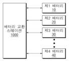
도 1은 본 문서에 개시된 일 실시예에 따른 배터리 교환 스테이션을 개념적으로 보여주는 도면이다.1 is a diagram conceptually showing a battery exchange station according to an embodiment disclosed in this document.
도 1을 참조하면, 배터리 교환 스테이션(BSS; Battery Swapping System, 1000)은 배터리의 분석, 평가, 충전, 교환 등의 배터리에 대한 전반적인 관리 서비스를 제공할 수 있으며, 본 개시에서는 배터리 교환 서비스를 중심으로 배터리 교환 스테이션(1000)의 기능을 설명하기로 한다. 여기서 배터리 교환 서비스는 서비스 대상이 되는 복수의 배터리(10, 20, 30, 40)의 상태를 분석하고, 분석 결과에 따라 배터리(10, 20, 30, 40)를 다른 배터리(10, 20, 30, 40)로 교환하는 서비스를 의미할 수 있다. 이러한 교환은 관리자 및/또는 사용자의 설정에 의해 자동적으로 수행될 수 있다. 예를 들어, 배터리 교환 스테이션(1000)은 사용자로부터 반납되는 배터리(10, 20, 30, 40)를 회수하고, 기 충전된 다른 배터리(10, 20, 30, 40)를 사용자에게 제공함으로써, 사용자에게 배터리 교환 서비스를 제공할 수 있다.Referring to FIG. 1, a battery swapping station (BSS; Battery Swapping System, 1000) can provide overall management services for batteries, such as battery analysis, evaluation, charging, and exchange. In this disclosure, the focus is on battery swapping services. The function of the
여기서 배터리(10, 20, 30, 40)는 대상 장치(예를 들어, EV(electrical vehicle), 전동 스쿠터, 전동 자전거 등의 전동식 이동 수단)에 장착되어 대상 장치의 구동을 위한 전원을 공급하는 장치로서, 배터리 팩(Battery Pack)의 형태로 구현될 수 있다. 배터리 팩은 전력을 저장하는 배터리와 배터리의 동작을 제어하는 배터리 관리 장치(BMS, Battery Management System)를 포함할 수 있다. 배터리는 배터리 관리 장치의 제어에 따라 전력을 저장하는 적어도 하나의 배터리 셀을 포함할 수 있다. 배터리 셀은 전기 에너지를 충방전하여 사용할 수 있는 배터리의 기본 단위로, 리튬이온(Li-ion) 전지, 리튬이온 폴리머(Li-ion polymer) 전지, 니켈 카드뮴(Ni-Cd) 전지, 니켈 수소(Ni-MH) 전지 등일 수 있으며, 이에 한정되지 않는다. 배터리 관리 장치는 배터리의 충전 및 방전을 제어할 수 있고, 일 실시예에 따라 외부의 요청에 따라 배터리의 상태 분석의 기초가 되는 데이터를 수집하여 외부로 전달할 수 있다.Here, the
이하에서 복수의 배터리(10, 20, 30, 40)는 배터리 팩의 형태로 구현되는 것으로 가정하여 설명한다. 한편, 도 1에서는 복수의 배터리(10, 20, 30, 40)가 4개인 것으로 도시되었지만, 이에 한정되는 것은 아니며, 배터리는 n(n은 2이상의 자연수)개의 배터리로 구성될 수 있다.Hereinafter, the plurality of
실시예에 따라, 배터리 교환 스테이션(1000)은 배터리 교환 서비스가 제공되는 서비스 스테이션에 배치되거나 서비스 스테이션과 별도의 공간에 배치될 수 있다.Depending on the embodiment, the
배터리 교환 스테이션(1000)은 접속되는 복수의 배터리(10, 20, 30, 40)에 대해 상태 분석을 진행하고, 상태 분석의 결과에 따라 배터리(10, 20, 30)를 다른 배터리(10, 20, 30)로 교환하거나 재사용(즉, 교환하지 않음)할 수 있다. 배터리 교환 스테이션(1000)은 복수의 배터리(10, 20, 30, 40)에 대한 상태 분석 및/또는 배터리(10, 20, 30)의 교환 필요 여부에 대한 판단을 자체적으로 수행할 수도 있으나, 다른 실시예에 따라 적어도 일부의 동작은 네트워크(network)로 연결되는 서버(예컨대, 클라우드 서버)와 연계하여 수행될 수 있다. 일 예로, 배터리 교환 스테이션(1000)은 클라우드 서버로 배터리의 교환 필요 여부에 대한 판단의 기초가 되는 정보를 전송하고, 클라우드 서버가 수신된 정보를 기초로 배터리의 교환 필요 여부에 대해 판단하여 배터리의 교환 필요 여부에 대한 정보를 배터리 교환 스테이션(1000)으로 전송할 수 있다.The
도 2는 본 문서에 개시된 다른 실시예에 따른 배터리 교환 스테이션을 개념적으로 보여주는 도면이다.Figure 2 is a diagram conceptually showing a battery exchange station according to another embodiment disclosed in this document.
도 2를 참조하면, 배터리 교환 스테이션(1000)은 배터리 슬롯부(100), 배터리 관리 장치(200) 및 충전기(300)를 포함할 수 있다.Referring to FIG. 2 , the
배터리 슬롯부(100)는 접속된 복수의 배터리(10, 20, 30, 40)를 수용할 수 있다. 배터리 슬롯부(100)는 접속된 복수의 배터리 각각을 수용하는 복수의 배터리 슬롯을 포함할 수 있다. 배터리 슬롯부(100)는 배터리 관리 장치(200)와 연결될 수 있다. 배터리 슬롯부(100)에 수용된 복수의 배터리(10, 20, 30, 40)는 배터리 관리 장치(200)의 제어 신호에 기초하여 물리적으로 제어될 수 있다,The
배터리 관리 장치(200)는 복수의 배터리(10, 20, 30, 40)의 상태 및/또는 동작을 관리 및/또는 제어할 수 있다. 배터리 관리 장치(200)는 복수의 배터리(10, 20, 30, 40)의 충전 및/또는 방전을 관리할 수 있다.The
또한, 배터리 관리 장치(200)는 복수의 배터리(10, 20, 30, 40) 각각의 전압, 전류, 온도 등을 모니터링 할 수 있다. 배터리 관리 장치(200)는 모니터링한 전압, 전류, 온도 등의 측정값에 기초하여 복수의 배터리(10, 20, 30, 40)의 상태를 나타내는 파라미터를 산출할 수 있다.Additionally, the
배터리 관리 장치(200)는 서비스 제공에 이용되는 복수의 배터리(10, 20, 30, 40)의 SOC(State of Charge) 및/또는 SOH(State of Health)를 관리할 수 있다. 배터리 관리 장치(200)는 복수의 배터리(10, 20, 30, 40)각각의 SOC(state of charge) 정보를 해당 배터리(10, 20, 30)로부터 수신할 수 있다. 여기서, SOC 정보는 해당 배터리의 현재 SOC를 나타내며, SOC는 해당 배터리에 포함된 배터리의 충전 상태 즉 잔존 용량 비율을 의미할 수 있다.The
해당 배터리의 배터리 관리 장치는 배터리의 현재 사용 가능한 용량을 배터리의 전체 용량으로 나누어 잔존 용량 비율을 산출할 수 있다. 일 예로, 잔존 용량 비율은 백분율로 산출될 수 있다. 다른 실시예에 따라, 배터리 관리 장치(200)는 해당 배터리의 배터리 관리 장치로부터 SOC 정보를 수신하지 않고 직접 해당 배터리의 배터리에 대한 잔존 용량 비율을 산출하여 SOC 정보를 획득할 수도 있다.The battery management device of the battery in question can calculate the remaining capacity ratio by dividing the currently available capacity of the battery by the total capacity of the battery. As an example, the remaining capacity ratio can be calculated as a percentage. According to another embodiment, the
충전기(300)는 배터리 관리 장치(200)의 제어에 따라 복수의 배터리(10, 20, 30, 40) 각각을 충전할 수 있다. 충전기(300)는 외부의 상용 전원으로부터 전원을 공급받아 복수의 배터리(10, 20, 30, 40)가 수신할 수 있는 전원 형태로 변환하여 복수의 배터리(10, 20, 30, 40)로 전원을 공급할 수 있다. 일 실시예에 따라, 충전기(300)는 복수의 배터리(10, 20, 30, 40)의 SOC가 100%가 될 때까지 전원을 공급하여 복수의 배터리(10, 20, 30, 40)를 완충시킬 수 있다.The
이하에서는 배터리 관리 장치(200)의 구성 및 동작에 대하여 도 3을 참조하여 더욱 구체적으로 설명한다.Hereinafter, the configuration and operation of the
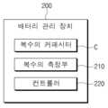
도 3은 본 문서에 개시된 일 실시예에 따른 배터리 관리 장치를 보여주는 블록도이다.Figure 3 is a block diagram showing a battery management device according to an embodiment disclosed in this document.
도 3을 참조하면, 배터리 관리 장치(200)는 복수의 커패시터(C), 복수의 측정부(210) 및 컨트롤러(230)를 포함할 수 있다.Referring to FIG. 3, the
배터리 관리 장치(200)는 복수의 배터리(10, 20, 30, 40)의 교류 임피던스를 측정할 수 있다. 예를 들어, 배터리 관리 장치(200)는 전기 화학 임피던스 분광법(Electrochemical Impedance Spectroscopy)을 이용하여 복수의 배터리(10, 20, 30, 40)의 교류 임피던스를 측정할 수 있다. 여기서 전기 화학 임피던스 분광법은 복수의 배터리(10, 20, 30, 40)의 전극에서 화학적 반응을 일으킬 때 전기 전달을 방해하는 요소인 임피던스를 검출할 수 있다. 배터리 관리 장치(200)는 전기 화학 임피던스 분광법을 이용하여 비파괴적 검사 방법으로 복수의 배터리(10, 20, 30, 40) 의 교류 임피던스 스팩트럼을 측정할 수 있다.The
배터리 관리 장치(200)는 복수의 배터리(10, 20, 30, 40) 의 교류 임피던스를 측정할 때, 복수의 배터리(10, 20, 30, 40)의 구동 초기에 발생할 수 있는 과전류인 돌입 전류(Inrush current)를 방지하기 위해 배터리에 커패시터(C)를 연결시켜 직류 전압(DC)을 생성할 수 있다. 여기서 배터리 관리 장치(200)가 배터리에 커패시터(C)를 연결시켜 커패시터(C)에 직류 전압(DC)을 생성한 것을 프리차징(Pre-charging) 으로 정의할 수 있고, 커패시터(C)에 충전된 전압을 프리차징 전압으로 정의할 수 있다.When measuring the alternating current impedance of the plurality of
복수의 커패시터(C) 각각은 복수의 배터리(10, 20, 30, 40) 중 적어도 하나의 배터리의 양단과 전기적으로 연결될 수 있다. 복수의 커패시터(C) 각각은 충전기(300)로부터 전류가 공급되어 충전될 수 있다. 복수의 커패시터(C)에 전류를 공급하여 직류 전압을 생성하는 시간을 프리차징 시간이라 할 수 있다.Each of the plurality of capacitors C may be electrically connected to both ends of at least one battery among the plurality of
복수의 측정부(210)는 복수의 커패시터(C)가 각각 전기적으로 연결된 복수의 배터리(10, 20, 30, 40)의 임피던스를 측정할 수 있다.The plurality of measuring
예를 들어, 배터리 교환 스테션(1000)에 8개의 배터리 슬롯이 구비된 경우, 복수의 측정부(210)는 1개의 측정부(210)로 구현될 수 있으며, 측정부(210)는 8개의 배터리 슬롯에 각각 투입된 8개의 배터리의 임피던스를 측정할 수 있다.For example, if the
또한, 예를 들어, 배터리 교환 스테션(1000)에 8개의 배터리 슬롯이 구비된 경우, 복수의 측정부(210)는 2개의 측정부(210)로 구현될 수 있으며, 2개의 측정부(210) 각각은 4개의 배터리 슬롯에 각각 투입된 4개의 배터리의 임피던스를 측정할 수 있다.In addition, for example, when the
복수의 측정부(210) 각각은 복수의 커패시터(C) 중 어느 하나의 커패시터와 전기적으로 연결될 수 있다.Each of the plurality of measuring
예를 들어, 배터리 교환 스테션(1000)에 8개의 배터리 슬롯이 구비된 경우, 복수의 측정부(210)는 1개의 측정부(210)로 구현될 수 있으며, 측정부(210)는 8개의 배터리에 연결된 8개의 커패시터(C)와 전기적으로 연결될 수 있다.For example, if the
또한, 예를 들어, 배터리 교환 스테션(1000)에 8개의 배터리 슬롯이 구비된 경우, 복수의 측정부(210)는 2개의 측정부(210)로 구현될 수 있으며, 2개의 측정부(210) 각각은 4개의 배터리에 연결된 4개의 커패시터(C)와 전기적으로 연결될 수 있다.In addition, for example, when the
복수의 측정부(210) 각각은 컨트롤러(220)의 제어 신호에 기초하여 복수의 배터리(10, 20, 30, 40)의 임피던스를 측정할 수 있다. 복수의 측정부(210)는 예를 들어, 전기 화학 임피던스 분광법(EIS)을 이용하여 복수의 배터리(10, 20, 30, 40)의 임피던스를 측정할 수 있다.Each of the plurality of measuring
복수의 측정부(210)는 복수의 배터리(10, 20, 30, 40)에 인가하는 교류(AC) 전원의 주파수를 변경함에 따라 복수의 배터리(10, 20, 30, 40)에서 검출되는 신호의 진폭과 위상 변화에 기초하여 복수의 배터리(10, 20, 30, 40)의 교류 임피던스 스팩트럼을 연산할 수 있다.The plurality of measuring
컨트롤러(220)는 복수의 커패시터(C)에 교류 전류를 인가하여 프리차징할 수 있다. 컨트롤러(220)는 복수의 커패시터(C) 각각의 전압을 측정할 수 있다.The
예를 들어, 컨트롤러(220)는 복수의 커패시터(C) 각각의 전압을 디지털 신호로 변환하는 아날로그 디지터 컨버터(ADC, Analog Digital Converter)로부터 복수의 커패시터(C) 각각의 전압을 획득할 수 있다.For example, the
컨트롤러(220)는 복수의 커패시터(C)의 전압이 임계 범위 이내인지 여부를 판단할 수 있다. 컨트롤러(220)는 복수의 커패시터(C)의 전압이 임계 범위 이내인지 여부에 기초하여 복수의 측정부(210)의 복수의 배터리(10, 20, 30, 40)의 임피던스 측정을 제어할 수 있다. 예를 들어, 컨트롤러(220)는 복수의 커패시터(C) 각각의 전압이 임계 범위인 1.8V±5% 이내인지 여부를 판단할 수 있다.The
컨트롤러(220)는 복수의 커패시터(C) 각각의 전압이 임계 범위 이내인 경우, 복수의 배터리(10, 20, 30, 40)의 임피던스를 측정하는 제어 신호를 생성하여 복수의 측정부(210)에 전달할 수 있다.When the voltage of each of the plurality of capacitors C is within the threshold range, the
컨트롤러(220)는 복수의 커패시터(C) 각각의 전압이 임계 범위 이외인 경우, 복수의 커패시터(C)를 프리차징한 프리차징 시간의 임계 시간 이상 여부를 판단할 수 있다. 예를 들어, 컨트롤러(220)는 복수의 커패시터(C) 각각의 전압이 임계 범위인 1.8V±5% 이외인 경우, 복수의 커패시터(C)의 프리차징 시간이 임계 시간인 4000ms 이상인지 여부를 판단할 수 있다.If the voltage of each of the plurality of capacitors C is outside the threshold range, the
컨트롤러(220)는 프리차징 시간이 임계 시간 이상인 경우, 일정 시간이 지난 후, 복수의 커패시터(C) 각각의 전압의 임계 범위 이내인지 여부를 재판단할 수 있다. 컨트롤러(220)는 복수의 커패시터(C) 각각의 전압의 임계 범위 이내인지 여부를 임계 횟수까지 재판단할 수 있다.If the precharging time is longer than the critical time, the
컨트롤러(220)는 커패시터(C) 각각의 전압의 임계 범위 이내인지 여부를 임계 횟수까지 재판단한 경우, 복수의 배터리(10, 20, 30, 40)의 이상 신호를 생성할 수 있다. 예를 들어, 컨트롤러(220) 는 복수의 커패시터(C) 각각의 전압의 임계 범위 이내인지 여부를 임계 횟수인 3회까지 재판단한 경우, 에러 신호를 생성할 수 있다.The
컨트롤러(220)는 프리차징 시간이 임계 시간 미만인 경우, 복수의 커패시터(C)를 계속 프리차징할 수 있다. 예를 들어, 컨트롤러(220)는 프리차징 시간이 임계 시간 미만인 경우, 커패시터(C)를 잔여 시간(

[수학식 1][Equation 1]

여기서 a는 환경 변수, 즉 커패시터(C)의 특성 값을 의미한다.


컨트롤러(220)는 [수학식 1]에 기초하여 잔여 시간(

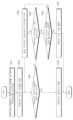
도 4는 본 문서에 개시된 일 실시예에 따른 차량 배터리 시스템의 배터리 팩을 개념적으로 보여주는 도면이다.FIG. 4 is a diagram conceptually showing a battery pack of a vehicle battery system according to an embodiment disclosed in this document.
도 4를 참조하면, 본 문서에 개시된 일 실시예에 따른 차량 배터리 시스템의 배터리 팩(2000)은 복수의 배터리 배터리 모듈(M1, M2, M3, M4), 배터리 관리 장치(200), 및 릴레이(R)를 포함할 수 있다.Referring to FIG. 4, the
실시예에 따라, 배터리 관리 장치(200)는 차량 배터리 시스템의 배터리 관리 장치로 구현될 수 있다.Depending on the embodiment, the
차량 배터리 시스템의 복수의 배터리 모듈(M1, M2, M3, M4)은 복수의 배터리 셀들을 포함할 수 있다. 도 4에서는 복수의 배터리 모듈(M1, M2, M3, M4)이 4개인 것으로 도시되었지만, 이에 한정되는 것은 아니며, 복수의 배터리 모듈(M1, M2, M3, M4)은 n(n은 2이상의 자연수)개의 배터리 셀들을 포함하여 구성될 수 있다.The plurality of battery modules (M1, M2, M3, M4) of the vehicle battery system may include a plurality of battery cells. In FIG. 4, there are four battery modules (M1, M2, M3, M4), but the number is not limited to this, and the plurality of battery modules (M1, M2, M3, M4) are n (n is a natural number of 2 or more). ) may be configured to include battery cells.
차량 배터리 시스템의 배터리 관리 장치(200)는 복수의 배터리 모듈(M1, M2, M3, M4)의 상태 및/또는 동작을 관리 및/또는 제어할 수 있다. 예를 들어, 배터리 관리 장치(200)는 복수의 배터리 모듈(M1, M2, M3, M4)에 포함된 복수의 배터리 셀들의 상태 및/또는 동작을 관리 및/또는 제어할 수 있다. 배터리 관리 장치(200)는 복수의 배터리 모듈(M1, M2, M3, M4)의 충전 및/또는 방전을 관리할 수 있다.The
또한, 배터리 관리 장치(200)는 복수의 배터리 모듈(M1, M2, M3, M4) 및/또는 복수의 배터리 모듈(M1, M2, M3, M4)에 포함된 복수의 배터리 셀들 각각의 전압, 전류, 온도 등을 모니터링 할 수 있다. 그리고 배터리 관리 장치(200)에 의한 모니터링을 위해 도시하지 않은 센서나 각종 측정 모듈이 복수의 배터리 모듈(M1, M2, M3, M4)이나 충방전 경로, 또는 복수의 배터리 모듈(M1, M2, M3, M4) 등의 임의의 위치에 추가로 설치될 수 있다.In addition, the
배터리 관리 장치(200)는 릴레이(R)의 동작을 제어할 수 있다. 예를 들어, 배터리 관리 장치(200)는 대상 장치에 전원을 공급하기 위해 릴레이(R)를 단락시킬 수 있다. 또한, 배터리 관리 장치(200)는 배터리 팩(1000)에 충전 장치가 연결되는 경우 릴레이(R)를 단락시킬 수 있다.The
복수의 배터리 모듈(M1, M2, M3, M4)의 교류 임피던스를 측정할 수 있다. 예를 들어, 배터리 관리 장치(200)는 전기 화학 임피던스 분광법(Electrochemical Impedance Spectroscopy)을 이용하여 복수의 배터리 모듈(M1, M2, M3, M4)의 교류 임피던스를 측정할 수 있다.The alternating current impedance of multiple battery modules (M1, M2, M3, M4) can be measured. For example, the
복수의 커패시터(C) 각각은 복수의 배터리 모듈(M1, M2, M3, M4) 중 적어도 하나의 배터리 모듈의 양단과 전기적으로 연결될 수 있다. 복수의 측정부(210)는 복수의 커패시터(C)가 각각 전기적으로 연결된 복수의 배터리 모듈(M1, M2, M3, M4)의 임피던스를 측정할 수 있다. 복수의 측정부(210) 각각은 복수의 커패시터(C) 중 어느 하나의 커패시터와 전기적으로 연결될 수 있다, 복수의 측정부(210) 각각은 컨트롤러(220)의 제어 신호에 기초하여 복수의 배터리 모듈(M1, M2, M3, M4)의 임피던스를 측정할 수 있다.Each of the plurality of capacitors C may be electrically connected to both ends of at least one battery module among the plurality of battery modules M1, M2, M3, and M4. The plurality of measuring
컨트롤러(220)는 복수의 커패시터(C)에 교류 전류를 인가하여 프리차징할 수 있다. 컨트롤러(220)는 복수의 커패시터(C) 각각의 전압을 측정할 수 있다. 예를 들어, 컨트롤러(220)는 복수의 커패시터(C) 각각의 전압을 디지털 신호로 변환하는 아날로그 디지터 컨버터(ADC, Analog Digital Converter)로부터 복수의 커패시터(C) 각각의 전압을 획득할 수 있다.The
컨트롤러(220)는 복수의 커패시터(C)의 전압이 임계 범위 이내인지 여부를 판단할 수 있다. 컨트롤러(220)는 복수의 커패시터(C)의 전압이 임계 범위 이내인지 여부에 기초하여 복수의 측정부(210)의 복수의 배터리 모듈(M1, M2, M3, M4)의 임피던스 측정을 제어할 수 있다.The
실시예에 따라, 배터리 관리 장치(200)는 기존 차량 배터리 시스템의 배터리 관리 장치 외부에 연결되어 차량 배터리 시스템의 배터리 관리 장치와 통신을 통해 복수의 배터리 모듈(M1, M2, M3, M4)의 임피던스를 측정할 수 있다.According to the embodiment, the
상술한 바와 같이, 본 문서에 개시된 일 실시예에 따른 배터리 관리 장치는 배터리에 연결된 커패시터들의 전압값을 모니터링하여 전기 화학 임피던스 분광법을 이용하여 측정한 배터리의 임피던스 값의 정확도를 개선할 수 있다.As described above, the battery management device according to an embodiment disclosed in this document can improve the accuracy of the impedance value of the battery measured using electrochemical impedance spectroscopy by monitoring the voltage values of capacitors connected to the battery.
도 5는 본 문서에 개시된 일 실시예에 따른 배터리 관리 장치의 동작 방법을 보여주는 흐름도이다.Figure 5 is a flowchart showing a method of operating a battery management device according to an embodiment disclosed in this document.
도 5를 참조하면, 본 문서에 개시된 일 실시예에 따른 배터리 관리 장치의 동작 방법은 복수의 배터리와 연결되는 복수의 커패시터에 전류를 인가하여 복수의 커패시터를 프리차징하는 단계(S101), 복수의 커패시터 각각의 전압을 측정하는 단계(S102) 및 복수의 커패시터 각각의 전압의 임계 범위 이내인지 여부에 기초하여 복수의 배터리의 임피던스를 측정하는 단계(S103)를 포함할 수 있다.Referring to FIG. 5, a method of operating a battery management device according to an embodiment disclosed in this document includes precharging a plurality of capacitors by applying current to a plurality of capacitors connected to a plurality of batteries (S101), a plurality of capacitors It may include measuring the voltage of each capacitor (S102) and measuring the impedance of the plurality of batteries based on whether the voltage of each of the plurality of capacitors is within a threshold range (S103).
이하에서 S101 단계 내지 S103 단계를 도 1 내지 도 4를 참조하여 구체적으로 설명된다. 배터리 관리 장치(200)는 도 1 내지 도 4를 참조하여 설명한 배터리 관리 장치(200)와 실질적으로 동일할 수 있으므로, 이하에서는 설명의 중복을 피하기 위하여 간략히 설명한다.Hereinafter, steps S101 to S103 will be described in detail with reference to FIGS. 1 to 4. Since the
S101 단계에서, 복수의 커패시터(C) 각각은 복수의 배터리(10, 20, 30, 40) 중 적어도 하나의 배터리의 양단과 전기적으로 연결될 수 있다.In step S101, each of the plurality of capacitors C may be electrically connected to both ends of at least one battery among the plurality of
S101 단계에서, 컨트롤러(220)는 복수의 커패시터(C)에 교류 전류를 인가하여 프리차징할 수 있다.In step S101, the
S102 단계에서, 컨트롤러(220)는 복수의 커패시터(C) 각각의 전압을 측정할 수 있다. S102 단계에서, 예를 들어, 컨트롤러(220)는 복수의 커패시터(C) 각각의 전압을 디지털 신호로 변환하는 아날로그 디지터 컨버터(ADC, Analog Digital Converter)로부터 복수의 커패시터(C) 각각의 전압을 획득할 수 있다.In step S102, the
S103 단계에서, 컨트롤러(220)는 복수의 커패시터(C)의 전압이 임계 범위 이내인지 여부를 판단할 수 있다. S103 단계에서, 컨트롤러(220)는 복수의 커패시터(C)의 전압이 임계 범위 이내인지 여부에 기초하여 복수의 측정부(210)의 복수의 배터리(10, 20, 30, 40)의 임피던스 측정을 제어할 수 있다. S103 단계에서, 예를 들어, 컨트롤러(220)는 복수의 커패시터(C) 각각의 전압이 임계 범위인 1.8V±5% 이내인지 여부를 판단할 수 있다.In step S103, the
S103 단계에서, 컨트롤러(220)는 복수의 커패시터(C) 각각의 전압이 임계 범위 이내인 경우, 복수의 배터리(10, 20, 30, 40)의 임피던스를 측정하는 제어 신호를 생성하여 복수의 측정부(210)에 전달할 수 있다.In step S103, when the voltage of each of the plurality of capacitors C is within the threshold range, the
S103 단계에서, 복수의 측정부(210) 각각은 컨트롤러(220)의 제어 신호에 기초하여 복수의 배터리(10, 20, 30, 40)의 임피던스를 측정할 수 있다. S103 단계에서, 복수의 측정부(210)는 예를 들어, 전기 화학 임피던스 분광법(EIS)을 이용하여 복수의 배터리(10, 20, 30, 40)의 임피던스를 측정할 수 있다.In step S103, each of the plurality of measuring
S103 단계에서, 복수의 측정부(210)는 복수의 배터리(10, 20, 30, 40)에 인가하는 교류(AC) 전원의 주파수를 변경함에 따라 복수의 배터리(10, 20, 30, 40)에서 검출되는 신호의 진폭과 위상 변화에 기초하여 복수의 배터리(10, 20, 30, 40)의 교류 임피던스 스팩트럼을 연산할 수 있다.In step S103, the plurality of measuring
도 6은 본 문서에 개시된 다른 실시예에 따른 배터리 관리 장치의 동작 방법을 보여주는 흐름도이다.Figure 6 is a flowchart showing a method of operating a battery management device according to another embodiment disclosed in this document.
도 6을 참조하면, 본 문서에 개시된 일 실시예에 따른 배터리 관리 장치의 동작 방법은 복수의 배터리와 연결되는 복수의 커패시터에 전류를 인가하여 복수의 커패시터를 프리차징하는 단계(S201), 복수의 커패시터 각각의 전압을 측정하는 단계(S202), 복수의 커패시터 각각의 전압의 임계 범위 이내 여부를 판단하는 단계(S203), 복수의 커패시터의 프리차징 시간의 임계 시간 이상 여부를 판단하는 단계(S204), 복수의 커패시터의 프리차징을 임계 시간까지 지속하는 단계(S205), 복수의 커패시터 각각의 전압의 임계 범위 이내 여부를 임계 횟수까지 재판단하는 단계(S206), 배터리 이상 신호를 출력하는 단계(S207) 및 배터리의 임피던스를 측정하는 단계(S208)를 포함할 수 있다.Referring to FIG. 6, a method of operating a battery management device according to an embodiment disclosed in this document includes precharging a plurality of capacitors by applying current to a plurality of capacitors connected to a plurality of batteries (S201), a plurality of capacitors Measuring the voltage of each capacitor (S202), determining whether the voltage of each of the plurality of capacitors is within a critical range (S203), and determining whether the precharging time of the plurality of capacitors is more than the threshold time (S204) , continuing precharging of the plurality of capacitors until a critical time (S205), re-determining whether the voltage of each of the plurality of capacitors is within the threshold range up to a threshold number of times (S206), and outputting a battery abnormality signal (S207) ) and measuring the impedance of the battery (S208).
이하에서 S201 단계 내지 S208 단계를 도 1 내지 도 4를 참조하여 구체적으로 설명된다. 배터리 관리 장치(200)는 도 1 내지 도 4를 참조하여 설명한 배터리 관리 장치(200)와 실질적으로 동일할 수 있으므로, 이하에서는 설명의 중복을 피하기 위하여 간략히 설명한다.Hereinafter, steps S201 to S208 will be described in detail with reference to FIGS. 1 to 4. Since the
S201 단계에서, 복수의 커패시터(C) 각각은 복수의 배터리(10, 20, 30, 40) 중 적어도 하나의 배터리의 양단과 전기적으로 연결될 수 있다.In step S201, each of the plurality of capacitors C may be electrically connected to both ends of at least one battery among the plurality of
S201 단계에서, 컨트롤러(220)는 복수의 커패시터(C)에 교류 전류를 인가하In step S201, the
S202 단계에서, 컨트롤러(220)는 복수의 커패시터(C) 각각의 전압을 측정할 수 있다. S102 단계에서, 예를 들어, 컨트롤러(220)는 복수의 커패시터(C) 각각의 전압을 디지털 신호로 변환하는 아날로그 디지터 컨버터(ADC, Analog Digital Converter)로부터 복수의 커패시터(C) 각각의 전압을 획득할 수 있다.In step S202, the
S203 단계에서, 컨트롤러(220)는 복수의 커패시터(C)의 전압이 임계 범위 이내인지 여부를 판단할 수 있다. S103 단계에서, 컨트롤러(220)는 복수의 커패시터(C)의 전압이 임계 범위 이내인지 여부에 기초하여 복수의 측정부(210)의 복수의 배터리(10, 20, 30, 40)의 임피던스 측정을 제어할 수 있다. S203 단계에서, 예를 들어, 컨트롤러(220)는 복수의 커패시터(C) 각각의 전압이 임계 범위인 1.8V±5% 이내인지 여부를 판단할 수 있다.In step S203, the
S204 단계에서, 컨트롤러(220)는 복수의 커패시터(C) 각각의 전압이 임계 범위 이외인 경우, 복수의 커패시터(C)를 프리차징한 프리차징 시간의 임계 시간 이상 여부를 판단할 수 있다. S204 단계에서 예를 들어, 컨트롤러(220)는 복수의 커패시터(C) 각각의 전압이 임계 범위인 1.8V±5% 이외인 경우, 복수의 커패시터(C)의 프리차징 시간이 임계 시간인 4000ms 이상인지 여부를 판단할 수 있다.In step S204, if the voltage of each of the plurality of capacitors C is outside the threshold range, the
S205 단계에서, 컨트롤러(220)는 프리차징 시간이 임계 시간 미만인 경우, 복수의 커패시터(C)를 계속 프리차징할 수 있다. S205 단계에서, 예를 들어, 컨트롤러(220)는 프리차징 시간이 임계 시간 미만인 경우, 커패시터(C)를 잔여 시간(

[수학식 1][Equation 1]

여기서 a는 환경 변수, 즉 커패시터(C)의 특성 값을 의미한다.


S205 단계에서, 컨트롤러(220)는 [수학식 1]에 기초하여 잔여 시간(

S206 단계에서, 컨트롤러(220)는 프리차징 시간이 임계 시간 이상인 경우, 일정 시간이 지난 후, 복수의 커패시터(C) 각각의 전압의 임계 범위 이내인지 여부를 재판단할 수 있다. S206 단계에서, 컨트롤러(220)는 복수의 커패시터(C) 각각의 전압의 임계 범위 이내인지 여부를 임계 횟수까지 재판단할 수 있다.In step S206, if the precharging time is longer than the critical time, the
S207 단계에서, 컨트롤러(220)는 커패시터(C) 각각의 전압의 임계 범위 이내인지 여부를 임계 횟수까지 재판단한 경우, 복수의 배터리(10, 20, 30, 40)의 이상 신호를 생성할 수 있다. S207 단계에서, 예를 들어, 컨트롤러(220) 는 복수의 커패시터(C) 각각의 전압의 임계 범위 이내인지 여부를 임계 횟수인 3회까지 재판단한 경우, 에러 신호를 생성할 수 있다.In step S207, when the
S208 단계에서, 컨트롤러(220)는 복수의 커패시터(C) 각각의 전압이 임계 범위 이내인 경우, 복수의 배터리(10, 20, 30, 40)의 임피던스를 측정하는 제어 신호를 생성하여 복수의 측정부(210)에 전달할 수 있다.In step S208, when the voltage of each of the plurality of capacitors C is within the threshold range, the
S208 단계에서, 복수의 측정부(210) 각각은 컨트롤러(220)의 제어 신호에 기초하여 복수의 배터리(10, 20, 30, 40)의 임피던스를 측정할 수 있다. S208 단계에서, 복수의 측정부(210)는 예를 들어, 전기 화학 임피던스 분광법(EIS)을 이용하여 복수의 배터리(10, 20, 30, 40)의 임피던스를 측정할 수 있다.In step S208, each of the plurality of measuring
도 7은 본 문서에 개시된 일 실시예에 따른 배터리 관리 장치의 동작 방법을 구현하는 컴퓨팅 시스템의 하드웨어 구성을 나타내는 블록도이다.Figure 7 is a block diagram showing the hardware configuration of a computing system that implements a method of operating a battery management device according to an embodiment disclosed in this document.
도 7을 참조하면, 본 문서에 개시된 일 실시 예에 따른 컴퓨팅 시스템(3000)은 MCU(3100), 메모리(3200), 입출력 I/F(3300) 및 통신 I/F(3400)를 포함할 수 있다.Referring to FIG. 7, the
MCU(3100)는 메모리(3200)에 저장되어 있는 각종 프로그램(예를 들면, 커패시터 전압 산출 프로그램)을 실행시키고, 이러한 프로그램들을 통해 복수의 배터리 셀의 SOC, SOH 등을 포함한 각종 데이터를 처리하며, 전술한 도 1을 참조하여 설명한 배터리 관리 장치(200)의 기능들을 수행하도록 하는 프로세서 또는 도 4를 참조하여 설명한 배터리 관리 장치의 동작 방법을 실행하는 프로세서일 수 있다.The
메모리(3200)는 복수의 배터리의 임피던스 산출에 관한 각종 프로그램을 저장할 수 있다. 또한, 메모리(3200)는 배터리 각각의 SOC, SOH 데이터 등 각종 데이터를 저장할 수 있다.The
이러한 메모리(3200)는 필요에 따라서 복수 개 마련될 수도 있을 것이다. 메모리(3200)는 휘발성 메모리일 수도 있으며 비휘발성 메모리일 수 있다. 휘발성 메모리로서의 메모리(3200)는 RAM, DRAM, SRAM 등이 사용될 수 있다. 비휘발성 메모리로서의 메모리(3200)는 ROM, PROM, EAROM, EPROM, EEPROM, 플래시 메모리 등이 사용될 수 있다. 상기 열거한 메모리(220)들의 예를 단지 예시일 뿐이며 이들 예로 한정되는 것은 아니다.A plurality of
입출력 I/F(3300)는, 키보드, 마우스, 터치 패널 등의 입력 장치(미도시)와 디스플레이(미도시) 등의 출력 장치와 MCU(3100) 사이를 연결하여 데이터를 송수신할 수 있도록 하는 인터페이스를 제공할 수 있다.The input/output I/
통신 I/F(3300)는 서버와 각종 데이터를 송수신할 수 있는 구성으로서, 유선 또는 무선 통신을 지원할 수 있는 각종 장치일 수 있다. 예를 들면, 통신 I/F(3300)를 통해 별도로 마련된 외부 서버로부터 배터리 셀의 SOH 산출이나 대상의 판정을 위한 프로그램이나 각종 데이터 등을 송수신할 수 있다.The communication I/
이와 같이, 본 문서에 개시된 일 실시 예에 따른 배터리 보호 장치의 동작 방법은 메모리(3200)에 기록되고, MCU(3100)에 의해 실행될 수 있다.As such, the operating method of the battery protection device according to an embodiment disclosed in this document may be recorded in the
이상의 설명은 본 문서에 개시된 기술 사상을 예시적으로 설명한 것에 불과한 것으로서, 본 문서에 개시된 실시예들이 속하는 기술 분야에서 통상의 지식을 가진 자라면 본 문서에 개시된 실시예들의 본질적인 특성에서 벗어나지 않는 범위에서 다양한 수정 및 변형이 가능할 것이다.The above description is merely an illustrative explanation of the technical idea disclosed in this document, and those of ordinary skill in the technical field to which the embodiments disclosed in this document belong will understand without departing from the essential characteristics of the embodiments disclosed in this document. Various modifications and variations will be possible.
따라서, 본 문서에 개시된 실시예들은 본 문서에 개시된 기술 사상을 한정하기 위한 것이 아니라 설명하기 위한 것이고, 이러한 실시예에 의하여 본 문서에 개시된 기술 사상의 범위가 한정되는 것은 아니다. 본 문서에 개시된 기술 사상의 보호 범위는 아래의 청구범위에 의하여 해석되어야 하며, 그와 동등한 범위 내에 있는 모든 기술 사상은 본 문서의 권리범위에 포함되는 것으로 해석되어야 할 것이다.Accordingly, the embodiments disclosed in this document are not intended to limit the technical ideas disclosed in this document, but rather to explain them, and the scope of the technical ideas disclosed in this document is not limited by these embodiments. The scope of protection of the technical ideas disclosed in this document shall be interpreted in accordance with the claims below, and all technical ideas within the equivalent scope shall be interpreted as being included in the scope of rights of this document.
10, 20, 30, 40: 복수의 배터리
1000: 배터리 교환 스테이션
100: 배터리 슬롯부
200: 배터리 관리 장치
C: 커패시터
210: 측정부
220: 컨트롤러
300: 충전기
2000: 배터리 팩
R: 릴레이
M1, M2, M3, M4: 배터리 모듈
3000: 컴퓨팅 시스템
3100: MCU
3200: 메모리
3300: 입출력 I/F
3400: 통신 I/F10, 20, 30, 40: Multiple Batteries
1000: Battery exchange station
100: Battery slot part
200: Battery management device
C: capacitor
210: measuring unit
220: controller
300: Charger
2000: Battery Pack
R: relay
M1, M2, M3, M4: Battery module
3000: Computing system
3100: MCU
3200: Memory
3300: Input/output I/F
3400: Communication I/F
Claims (14)
Translated fromKorean상기 적어도 하나의 커패시터에 전류를 인가하여 프리차징하고, 상기 적어도 하나의 커패시터 각각의 전압을 측정하고, 상기 적어도 하나의 커패시터의 전압이 임계 범위 이내인지 여부에 기초하여 상기 적어도 하나의 배터리의 임피던스 측정 을 제어하는 컨트롤러를 포함하는 배터리 관리 장치.
at least one capacitor each connected to at least one battery; and
Precharging by applying a current to the at least one capacitor, measuring the voltage of each of the at least one capacitor, and measuring the impedance of the at least one battery based on whether the voltage of the at least one capacitor is within a threshold range. A battery management device including a controller that controls.
상기 배터리의 임피던스를 측정하는 적어도 하나의 측정부를 더 포함하고,
상기 적어도 하나의 측정부는 상기 컨트롤러의 제어 신호에 기초하여 상기 배터리의 임피던스를 측정하고,
상기 컨트롤러는 상기 커패시터 각각의 전압이 임계 범위 이내인 경우, 상기 배터리의 임피던스를 측정하는 제어 신호를 생성하여 상기 적어도 하나의 측정부에 전달하는 것을 특징으로 하는 배터리 관리 장치.
According to claim 1,
Further comprising at least one measuring unit that measures the impedance of the battery,
The at least one measuring unit measures the impedance of the battery based on a control signal from the controller,
The controller generates a control signal for measuring the impedance of the battery when the voltage of each capacitor is within a critical range and transmits the control signal to the at least one measuring unit.
상기 컨트롤러는 상기 커패시터 각각의 전압이 임계 범위 이외인 경우, 상기 적어도 하나의 커패시터를 프리차징한 프리차징 시간의 임계 시간 이상 여부를 판단하는 것을 특징으로 하는 배터리 관리 장치.
According to claim 1,
The controller is a battery management device characterized in that, when the voltage of each of the capacitors is outside the threshold range, the controller determines whether the precharging time for precharging the at least one capacitor is greater than or equal to a threshold time.
상기 컨트롤러는 상기 커패시터 각각의 전압이 임계 범위 이외인 경우, 상기 커패시터를 프리차징한 프리차징 시간의 임계 시간 이상 여부를 판단하는 것을 특징으로 하는 배터리 관리 장치.
According to clause 3,
The controller is a battery management device characterized in that, when the voltage of each of the capacitors is outside the threshold range, the controller determines whether the precharging time for precharging the capacitor is more than a threshold time.
상기 컨트롤러는 상기 프리차징 시간이 상기 임계 시간 이상인 경우, 상기 커패시터 각각의 전압의 임계 범위 이내인지 여부를 재판단하는 것을 특징으로 하는 배터리 관리 장치.
According to clause 4,
The battery management device, wherein the controller re-determines whether the voltage of each capacitor is within a threshold range when the precharging time is greater than or equal to the threshold time.
상기 컨트롤러는 상기 커패시터 각각의 전압의 임계 범위 이내인지 여부를 임계 횟수까지 재판단한 경우, 상기 배터리의 이상 신호를 생성하는 것을 특징으로 하는 배터리 관리 장치.
According to clause 5,
The battery management device, wherein the controller generates an abnormal signal of the battery when it re-determines whether the voltage of each capacitor is within a threshold range up to a threshold number of times.
상기 컨트롤러는 상기 프리차징 시간이 상기 임계 시간 미만인 경우, 상기 커패시터를 프리차징하는 것을 특징으로 하는 배터리 관리 장치.
According to clause 4,
The controller is configured to precharge the capacitor when the precharging time is less than the threshold time.
상기 커패시터 각각의 전압을 측정하는 단계; 및
상기 커패시터 각각의 전압의 임계 범위 이내인지 여부에 기초하여 상기 배터리의 임피던스를 측정하는 단계를 포함하는 배터리 관리 장치의 동작 방법.
Pre-charging the capacitor by applying current to the capacitor connected to the battery;
measuring the voltage of each capacitor; and
A method of operating a battery management device comprising measuring the impedance of the battery based on whether the voltage of each of the capacitors is within a critical range.
상기 커패시터 각각의 전압의 임계 범위 이내인지 여부에 기초하여 상기 배터리의 임피던스를 측정하는 단계는
상기 커패시터 각각의 전압이 임계 범위 이내인 경우, 상기 배터리의 임피던스를 측정하는 제어 신호를 생성하여 상기 적어도 하나의 커패시터에 전달하는 것을 특징으로 하는 배터리 관리 장치의 동작 방법.
According to clause 8,
Measuring the impedance of the battery based on whether the voltage of each capacitor is within a critical range is
When the voltage of each capacitor is within a critical range, a control signal for measuring impedance of the battery is generated and transmitted to the at least one capacitor.
상기 커패시터 각각의 전압의 임계 범위 이내인지 여부에 기초하여 상기 배터리의 임피던스를 측정하는 단계는
상기 커패시터 각각의 전압이 임계 범위 이외인 경우, 상기 커패시터를 프리차징한 프리차징 시간의 임계 시간 이상 여부를 판단하는 것을 특징으로 하는 배터리 관리 장치의 동작 방법.
According to clause 8,
Measuring the impedance of the battery based on whether the voltage of each capacitor is within a critical range is
A method of operating a battery management device, characterized in that, when the voltage of each of the capacitors is outside the threshold range, it is determined whether the precharging time for precharging the capacitor is more than a threshold time.
상기 커패시터를 프리차징한 프리차징 시간의 임계 시간 이상 여부를 판단하는 단계를 더 포함하는 것을 특징으로 하는 배터리 관리 장치의 동작 방법.
According to claim 10,
A method of operating a battery management device, further comprising determining whether a precharging time for precharging the capacitor is longer than or equal to a threshold time.
상기 커패시터를 프리차징한 프리차징 시간의 임계 시간 이상 여부를 판단하는 단계는
상기 프리차징 시간이 상기 임계 시간 이상인 경우, 상기 커패시터 각각의 전압의 임계 범위 이내인지 여부를 재판단하는 것을 특징으로 하는 배터리 관리 장치의 동작 방법.
According to claim 11,
The step of determining whether the precharging time for precharging the capacitor is more than the critical time is
A method of operating a battery management device, characterized in that, when the precharging time is more than the threshold time, it is re-determined whether the voltage of each capacitor is within a threshold range.
상기 커패시터를 프리차징한 프리차징 시간의 임계 시간 이상 여부를 판단하는 단계는
상기 커패시터 각각의 전압의 임계 범위 이내인지 여부를 임계 횟수까지 재판단한 경우, 상기 배터리의 이상 신호를 생성하는 것을 특징으로 하는 배터리 관리 장치의 동작 방법.
According to claim 12,
The step of determining whether the precharging time for precharging the capacitor is more than the critical time is
A method of operating a battery management device, characterized in that generating an abnormal signal of the battery when re-determining whether the voltage of each capacitor is within a threshold range up to a threshold number of times.
상기 커패시터를 프리차징한 프리차징 시간의 임계 시간 이상 여부를 판단하는 단계는
상기 프리차징 시간이 상기 임계 시간 미만인 경우, 상기 커패시터를 프리차징하는 제어 신호를 생성하여 상기 적어도 하나의 커패시터에 전달하는 것을 특징으로 하는 배터리 관리 장치의 동작 방법.According to claim 11,
The step of determining whether the precharging time for precharging the capacitor is more than the critical time is
When the precharging time is less than the threshold time, a control signal for precharging the capacitor is generated and transmitted to the at least one capacitor.
Priority Applications (4)
| Application Number | Priority Date | Filing Date | Title |
|---|---|---|---|
| KR1020220135174AKR20240054783A (en) | 2022-10-19 | 2022-10-19 | Apparatus for managing battery and operating method of the same |
| EP23880006.4AEP4607219A1 (en) | 2022-10-19 | 2023-09-01 | Battery management device and operating method therefor |
| PCT/KR2023/013096WO2024085426A1 (en) | 2022-10-19 | 2023-09-01 | Battery management device and operating method therefor |
| CN202380064275.9ACN119836577A (en) | 2022-10-19 | 2023-09-01 | Battery management apparatus and method of operating the same |
Applications Claiming Priority (1)
| Application Number | Priority Date | Filing Date | Title |
|---|---|---|---|
| KR1020220135174AKR20240054783A (en) | 2022-10-19 | 2022-10-19 | Apparatus for managing battery and operating method of the same |
Publications (1)
| Publication Number | Publication Date |
|---|---|
| KR20240054783Atrue KR20240054783A (en) | 2024-04-26 |
Family
ID=90737796
Family Applications (1)
| Application Number | Title | Priority Date | Filing Date |
|---|---|---|---|
| KR1020220135174APendingKR20240054783A (en) | 2022-10-19 | 2022-10-19 | Apparatus for managing battery and operating method of the same |
Country Status (4)
| Country | Link |
|---|---|
| EP (1) | EP4607219A1 (en) |
| KR (1) | KR20240054783A (en) |
| CN (1) | CN119836577A (en) |
| WO (1) | WO2024085426A1 (en) |
Family Cites Families (5)
| Publication number | Priority date | Publication date | Assignee | Title |
|---|---|---|---|---|
| US6631293B2 (en)* | 1997-09-15 | 2003-10-07 | Cardiac Pacemakers, Inc. | Method for monitoring end of life for battery |
| KR102255523B1 (en)* | 2016-06-07 | 2021-05-25 | 주식회사 엘지에너지솔루션 | Battery charging apparatus for increasing battery life and battery charging method of the same |
| KR102862005B1 (en)* | 2019-12-04 | 2025-09-18 | 주식회사 엘지에너지솔루션 | Battery management system, battery management method and battery pack |
| EP3863103A1 (en)* | 2020-02-06 | 2021-08-11 | Samsung SDI Co., Ltd. | Battery system |
| KR102367775B1 (en)* | 2021-08-17 | 2022-02-24 | 울산대학교 산학협력단 | Method and apparatus for measuring impedance of battery cell on-line |
- 2022
- 2022-10-19KRKR1020220135174Apatent/KR20240054783A/enactivePending
- 2023
- 2023-09-01CNCN202380064275.9Apatent/CN119836577A/enactivePending
- 2023-09-01WOPCT/KR2023/013096patent/WO2024085426A1/ennot_activeCeased
- 2023-09-01EPEP23880006.4Apatent/EP4607219A1/enactivePending
Also Published As
| Publication number | Publication date |
|---|---|
| WO2024085426A1 (en) | 2024-04-25 |
| EP4607219A1 (en) | 2025-08-27 |
| CN119836577A (en) | 2025-04-15 |
Similar Documents
| Publication | Publication Date | Title |
|---|---|---|
| JP6823162B2 (en) | Battery management device and method for calibrating the charge status of the battery | |
| KR101497602B1 (en) | Balancing system for battery and Method for balancing of battery using the same | |
| JP5715694B2 (en) | Battery control device, battery system | |
| US9653759B2 (en) | Method and apparatus for optimized battery life cycle management | |
| US10725111B2 (en) | Battery state detection device, secondary battery system, program product, and battery state detection method | |
| KR102436418B1 (en) | Method for Detecting Battery Pack Current | |
| US10686229B2 (en) | Battery state detection device, secondary battery system, program product, and battery state detection method | |
| JP2017123327A (en) | Battery control device and battery control system | |
| US20130207616A1 (en) | Battery system, controlling method of the same, and power storage system including the battery pack | |
| KR101463394B1 (en) | Battery management system, and method of estimating battery's state of charge using the same | |
| US9184600B2 (en) | Method for balancing the voltages of electrochemical cells connected in several parallel branches | |
| US11967847B2 (en) | Battery bank control device and method | |
| US20150293181A1 (en) | Secondary battery tester | |
| KR20140051881A (en) | Apparatus for battery management using battery's state of health and method thereof | |
| EP4451418A1 (en) | Battery management device and operation method thereof | |
| KR20230120853A (en) | Method of estimation the unbalance between battery cells through analysis of the cells equalization process and The Energy Management System using the same. | |
| KR20240054783A (en) | Apparatus for managing battery and operating method of the same | |
| KR20210149467A (en) | Apparatus for balancing of battery pack in electric vehicle and method thereof | |
| JP2025534597A (en) | Battery management device and method of operation thereof | |
| JP2023516649A (en) | Battery management device and method, battery management system | |
| KR20220117063A (en) | Battery charge and discharge apparatus and method | |
| EP4503379A1 (en) | Battery swapping system and operation method therefor | |
| KR102814753B1 (en) | Battery and operating method of the same | |
| Gallo et al. | Advanced parameter measurement of energy storage systems for smart grids application | |
| Saravanan et al. | Methodology for low-cost self reconfiguration process |
Legal Events
| Date | Code | Title | Description |
|---|---|---|---|
| PA0109 | Patent application | Patent event code:PA01091R01D Comment text:Patent Application Patent event date:20221019 | |
| A201 | Request for examination | ||
| PA0201 | Request for examination | Patent event code:PA02012R01D Patent event date:20240227 Comment text:Request for Examination of Application Patent event code:PA02011R01I Patent event date:20221019 Comment text:Patent Application | |
| PG1501 | Laying open of application | ||
| E902 | Notification of reason for refusal | ||
| PE0902 | Notice of grounds for rejection | Comment text:Notification of reason for refusal Patent event date:20250224 Patent event code:PE09021S01D |