KR20240052986A - flexible small endoscope - Google Patents
flexible small endoscopeDownload PDFInfo
- Publication number
- KR20240052986A KR20240052986AKR1020247011517AKR20247011517AKR20240052986AKR 20240052986 AKR20240052986 AKR 20240052986AKR 1020247011517 AKR1020247011517 AKR 1020247011517AKR 20247011517 AKR20247011517 AKR 20247011517AKR 20240052986 AKR20240052986 AKR 20240052986A
- Authority
- KR
- South Korea
- Prior art keywords
- optical fiber
- endoscopic device
- steering section
- steering
- section
- Prior art date
- Legal status (The legal status is an assumption and is not a legal conclusion. Google has not performed a legal analysis and makes no representation as to the accuracy of the status listed.)
- Pending
Links
Images


Classifications
- A—HUMAN NECESSITIES
- A61—MEDICAL OR VETERINARY SCIENCE; HYGIENE
- A61B—DIAGNOSIS; SURGERY; IDENTIFICATION
- A61B1/00—Instruments for performing medical examinations of the interior of cavities or tubes of the body by visual or photographical inspection, e.g. endoscopes; Illuminating arrangements therefor
- A61B1/005—Flexible endoscopes
- A61B1/0051—Flexible endoscopes with controlled bending of insertion part
- A61B1/0055—Constructional details of insertion parts, e.g. vertebral elements
- A—HUMAN NECESSITIES
- A61—MEDICAL OR VETERINARY SCIENCE; HYGIENE
- A61B—DIAGNOSIS; SURGERY; IDENTIFICATION
- A61B1/00—Instruments for performing medical examinations of the interior of cavities or tubes of the body by visual or photographical inspection, e.g. endoscopes; Illuminating arrangements therefor
- A61B1/00064—Constructional details of the endoscope body
- A61B1/00071—Insertion part of the endoscope body
- A61B1/0008—Insertion part of the endoscope body characterised by distal tip features
- A61B1/00096—Optical elements
- A—HUMAN NECESSITIES
- A61—MEDICAL OR VETERINARY SCIENCE; HYGIENE
- A61B—DIAGNOSIS; SURGERY; IDENTIFICATION
- A61B1/00—Instruments for performing medical examinations of the interior of cavities or tubes of the body by visual or photographical inspection, e.g. endoscopes; Illuminating arrangements therefor
- A61B1/005—Flexible endoscopes
- A61B1/0051—Flexible endoscopes with controlled bending of insertion part
- A61B1/0057—Constructional details of force transmission elements, e.g. control wires
- A—HUMAN NECESSITIES
- A61—MEDICAL OR VETERINARY SCIENCE; HYGIENE
- A61B—DIAGNOSIS; SURGERY; IDENTIFICATION
- A61B1/00—Instruments for performing medical examinations of the interior of cavities or tubes of the body by visual or photographical inspection, e.g. endoscopes; Illuminating arrangements therefor
- A61B1/012—Instruments for performing medical examinations of the interior of cavities or tubes of the body by visual or photographical inspection, e.g. endoscopes; Illuminating arrangements therefor characterised by internal passages or accessories therefor
- A61B1/015—Control of fluid supply or evacuation
- A—HUMAN NECESSITIES
- A61—MEDICAL OR VETERINARY SCIENCE; HYGIENE
- A61B—DIAGNOSIS; SURGERY; IDENTIFICATION
- A61B1/00—Instruments for performing medical examinations of the interior of cavities or tubes of the body by visual or photographical inspection, e.g. endoscopes; Illuminating arrangements therefor
- A61B1/012—Instruments for performing medical examinations of the interior of cavities or tubes of the body by visual or photographical inspection, e.g. endoscopes; Illuminating arrangements therefor characterised by internal passages or accessories therefor
- A61B1/018—Instruments for performing medical examinations of the interior of cavities or tubes of the body by visual or photographical inspection, e.g. endoscopes; Illuminating arrangements therefor characterised by internal passages or accessories therefor for receiving instruments
- A—HUMAN NECESSITIES
- A61—MEDICAL OR VETERINARY SCIENCE; HYGIENE
- A61B—DIAGNOSIS; SURGERY; IDENTIFICATION
- A61B1/00—Instruments for performing medical examinations of the interior of cavities or tubes of the body by visual or photographical inspection, e.g. endoscopes; Illuminating arrangements therefor
- A61B1/04—Instruments for performing medical examinations of the interior of cavities or tubes of the body by visual or photographical inspection, e.g. endoscopes; Illuminating arrangements therefor combined with photographic or television appliances
- A61B1/05—Instruments for performing medical examinations of the interior of cavities or tubes of the body by visual or photographical inspection, e.g. endoscopes; Illuminating arrangements therefor combined with photographic or television appliances characterised by the image sensor, e.g. camera, being in the distal end portion
- A—HUMAN NECESSITIES
- A61—MEDICAL OR VETERINARY SCIENCE; HYGIENE
- A61B—DIAGNOSIS; SURGERY; IDENTIFICATION
- A61B1/00—Instruments for performing medical examinations of the interior of cavities or tubes of the body by visual or photographical inspection, e.g. endoscopes; Illuminating arrangements therefor
- A61B1/04—Instruments for performing medical examinations of the interior of cavities or tubes of the body by visual or photographical inspection, e.g. endoscopes; Illuminating arrangements therefor combined with photographic or television appliances
- A61B1/055—Instruments for performing medical examinations of the interior of cavities or tubes of the body by visual or photographical inspection, e.g. endoscopes; Illuminating arrangements therefor combined with photographic or television appliances having rod-lens arrangements
- A—HUMAN NECESSITIES
- A61—MEDICAL OR VETERINARY SCIENCE; HYGIENE
- A61B—DIAGNOSIS; SURGERY; IDENTIFICATION
- A61B1/00—Instruments for performing medical examinations of the interior of cavities or tubes of the body by visual or photographical inspection, e.g. endoscopes; Illuminating arrangements therefor
- A61B1/06—Instruments for performing medical examinations of the interior of cavities or tubes of the body by visual or photographical inspection, e.g. endoscopes; Illuminating arrangements therefor with illuminating arrangements
- A61B1/07—Instruments for performing medical examinations of the interior of cavities or tubes of the body by visual or photographical inspection, e.g. endoscopes; Illuminating arrangements therefor with illuminating arrangements using light-conductive means, e.g. optical fibres
Landscapes
- Health & Medical Sciences (AREA)
- Life Sciences & Earth Sciences (AREA)
- Surgery (AREA)
- Biomedical Technology (AREA)
- Medical Informatics (AREA)
- Optics & Photonics (AREA)
- Pathology (AREA)
- Radiology & Medical Imaging (AREA)
- Biophysics (AREA)
- Engineering & Computer Science (AREA)
- Physics & Mathematics (AREA)
- Heart & Thoracic Surgery (AREA)
- Nuclear Medicine, Radiotherapy & Molecular Imaging (AREA)
- Molecular Biology (AREA)
- Animal Behavior & Ethology (AREA)
- General Health & Medical Sciences (AREA)
- Public Health (AREA)
- Veterinary Medicine (AREA)
- Laser Surgery Devices (AREA)
- Endoscopes (AREA)
Abstract
Translated fromKoreanDescription
Translated fromKorean관련출원Related applications
본 출원은 2021년 9월 10일자로 출원된 미국 가출원 제 63/242,523 호의 이익 향유를 주장하고, 상기 가출원의 개시내용 전체가 여기에서 참조로서 포함된다.This application claims the benefit of U.S. Provisional Application No. 63/242,523, filed September 10, 2021, the entire disclosure of which is incorporated herein by reference.
기술분야Technology field
본 출원은 일반적으로 내시경 장치 및 방법에 관한 것이다. 더 구체적으로, 본 출원은 인간 및 동물의 결석 및 조직의 레이저 치료를 위한 가요성, 반강성 및 강성 레이저 내시경에 관한 것이다.This application relates generally to endoscopic devices and methods. More specifically, the present application relates to flexible, semi-rigid and rigid laser endoscopes for laser treatment of stones and tissues in humans and animals.
매년 500명 중 1명의 미국인에게 신장 결석이 발병하며, 상당한 통증 및 의료 비용을 야기한다. 증후성 신장 결석을 갖는 환자에 대한 수술 옵션은 체외 충격파 쇄석술(extracorporeal shock wave lithotripsy: ESWL), 요관경술(ureteroscopy), 및 경피적 신쇄석술(percutaneous nephrolithotomy: PCNL)을 포함한다. 사람의 신장 해부학적 구조, 결석 조성, 및 신체 습관은 모두 결과 및 치료 접근법을 결정하는데 중요한 역할을 한다.Kidney stones affect one in 500 Americans each year, causing significant pain and medical costs. Surgical options for patients with symptomatic kidney stones include extracorporeal shock wave lithotripsy (ESWL), ureteroscopy, and percutaneous nephrolithotomy (PCNL). A person's kidney anatomy, stone composition, and body habits all play an important role in determining outcome and treatment approach.
가요성 카테터 샤프트의 직경 감소, 향상된 조향 및 편향 능력, 비디오-이미징의 개선, 바스켓 및 기구의 소형화, 및 홀뮴(Ho) 및 툴륨(Tm) 레이저의 출현과 함께 쇄석술(lithotripsy, 결석 파괴)의 발전으로 인해 지난 10년에 걸쳐 요관경술의 역할이 증가되었다. 이제 미국 내 모든 신장 결석 수술의 45% 이상이 소형 요관경 기술 및 레이저를 사용하여 수행된다.Advances in lithotripsy (stone destruction) with reduced diameters of flexible catheter shafts, improved steering and deflection capabilities, improvements in video-imaging, miniaturization of baskets and instruments, and the advent of holmium (Ho) and thulium (Tm) lasers. As a result, the role of ureteroscopy has increased over the past 10 years. More than 45% of all kidney stone surgeries in the United States are now performed using mini-ureteroscopic techniques and lasers.
요관경술은 신장 결석을 직접 보고 치료하기 위해 요관경이라 불리는 소형 가요성 또는 강성 장치의 사용을 수반한다. 비디오 이미지를 제공하고 작은 "작업" 채널을 갖는 요관경 장치는, 신장 결석이 발견될때까지 방광 안으로 그리고 요관 위로 삽입된다. 그런 다음 광섬유(레이저 섬유)를 통해서 표적 부위로 전달되는 레이저 에너지로 신장 결석이 파괴될 수 있고, 그리고/또는 작은 바스켓을 이용하여 추출될 수 있다. 이러한 유형의 수술의 장점은, 신체 오리피스가 접근을 위해서 이용되어, 절개를 필요로 하지 않는다는 것이다.Ureteroscopy involves the use of a small flexible or rigid device called a ureteroscope to directly view and treat kidney stones. A ureteroscopic device, which provides video images and has a small "working" channel, is inserted into the bladder and up the ureter until a kidney stone is found. Kidney stones can then be destroyed with laser energy delivered to the target area through an optical fiber (laser fiber) and/or extracted using a small basket. The advantage of this type of surgery is that a body orifice is used for access, so no incision is required.
요관경술은 종종 요관이나 신장의 작은 신장 결석에 대한 좋은 옵션이다. 더 작은 신장 결석을 제거하기 위한 요관경술에 대한 성공률은 일반적으로 충격파 쇄석술에 대한 것보다 높다. 레이저 요관경술의 경우, 신장 결석은 목적에 최적화된 레이저 세팅을 사용하여 1mm 미만 또는 심지어 0.25mm 미만의 최대 치수를 갖는 작은 입자로 파괴될 수 있다. 이 경우에, 절제의 산물이 관주 유동에 의해 또는 수술 후에 신장으로부터 방광으로의 자연 유출에 기인하여 제거되어 무결석 치료 결과를 제공할 수 있다.Ureteroscopy is often a good option for small kidney stones in the ureter or kidney. Success rates for ureteroscopy to remove smaller kidney stones are generally higher than for shock wave lithotripsy. In the case of laser ureteroscopy, kidney stones can be broken down into small particles with a maximum dimension of less than 1 mm or even less than 0.25 mm using laser settings optimized for the purpose. In this case, the products of the resection can be removed by irrigation flow or due to natural outflow from the kidney to the bladder after surgery, providing a stone-free treatment result.
그러나, 요관경술은 매우 큰 신장 결석(예컨대, 20mm보다 큰 치수)의 경우 항상 잘 작동하지는 않는데, 이는 큰 크기로 인해 긴 치료 시간이 필요하고 그러한 결석의 조각을 제거하는 데 어려움을 초래할 수 있기 때문이다. 또한, 중간 크기의 결석 또는 조각(예컨대, 최대 치수가 1~5mm)은 접촉 기술을 사용하여 레이저로 치료하기 어려울 수 있다. 예를 들어, 접촉 모드에서 동작하는 요관경은 강한 역추진 효과를 받을 수 있으며, 따라서 비접촉 모드(예를 들면, "팝코닝(popcorning)")에서의 동작을 필요로 하며, 이는 시간 소모적이고 무결석 결과를 보장하지 않는다. 그 결과, 요관경검사는 매우 큰 신장 결석의 경우 항상 잘 작동하지는 않는데, 이는 큰 크기가 긴 치료 시간을 필요로 하고 그러한 결석의 조각을 제거하는 데 어려움을 초래할 수 있기 때문이다. 이러한 경우에, 경피적 접근법이 최선의 이용 가능한 옵션일 수도 있다.However, ureteroscopy does not always work well for very large kidney stones (e.g., dimensions greater than 20 mm) because their large size requires a long treatment time and may lead to difficulties in removing fragments of such stones. am. Additionally, medium-sized stones or fragments (e.g., 1 to 5 mm in greatest dimension) may be difficult to treat with laser using contact techniques. For example, ureteroscopes operating in contact mode may be subject to strong counter-propulsion effects, thus necessitating operation in non-contact mode (e.g., “popcorning”), which is time-consuming and results in stone-free outcomes. does not guarantee As a result, ureteroscopy does not always work well for very large kidney stones because their large size requires a long treatment time and can lead to difficulties in removing fragments of such stones. In these cases, a percutaneous approach may be the best available option.
요관경술의 이러한 단점을 완화하거나 해결하는 장치 및 부속 기술이 환영받을 것이다.Devices and adjunctive technologies that alleviate or address these shortcomings of ureteroscopy would be welcome.
본 개시내용의 다양한 실시예는, 개시된 장치를 더욱 민첩하게 하는 향상된 조향 능력을 제시할 뿐만 아니라, 종래의 요관경에 비해 감소된 단면을 갖는 소형 내시경을 제공함으로써 종래의 요관경의 특정 단점을 완화시키는 내시경 수술 기구 및 방법을 제시한다. 감소된 단면은, 긴 기간을 필요로 하는 치료 중에, 예를 들어 더 큰 신장 결석을 제거할 때, 불편함을 줄여준다. 증가된 민첩성은 치료 중에 결석을 추적(track) 또는 "추종(chase)"하는 것을 더 쉽게 만들고, 이에 의해 치료 시간을 감소시키고 더 높은 무결석 결과의 가능성을 제공한다.Various embodiments of the present disclosure provide improved steering capabilities that make the disclosed device more agile, as well as mitigating certain disadvantages of conventional ureteroscopes by providing a compact endoscope with a reduced cross-section compared to conventional ureteroscopes. Presents endoscopic surgical instruments and methods. The reduced cross-section reduces discomfort during treatments that require a long period of time, for example when removing larger kidney stones. Increased agility makes it easier to track or “chase” stones during treatment, thereby reducing treatment time and providing a higher likelihood of stone-free outcomes.
본 개시내용은 Altshuler 등의 국제 특허 출원 공개 번호 WO 2020/150713을 기반으로 하고, 그 개시내용은 그 안에 포함되는 명시적 형성 및 특허 청구범위를 제외하고 그 전체가 본 명세서에 통합된다. Altshuler는 큰 신장 결석을 제거하기 위한 레이저 절제 요관경술의 몇 가지 단점을 해결한다. 본 개시내용은 Altshuler의 특정 실시예에 대한 개선을 나타낸다.This disclosure is based on International Patent Application Publication No. WO 2020/150713 by Altshuler et al., the disclosure of which is incorporated herein in its entirety except for the express forms and claims contained therein. Altshuler addresses some of the drawbacks of laser ablation ureteroscopy to remove large kidney stones. This disclosure represents improvements to certain embodiments of Altshuler.
본 개시내용의 다양한 실시예는 견인 와이어(pull wire) 및 토션 슬리브(torsion sleeve)에 대한 필요성을 제거함으로써 종래의 내시경보다 더 콤팩트한 반경방향 프로파일을 갖는 카테터 단면을 제공한다. 조향 기능을 수행하기 위한 광섬유, 특히 단일 광섬유의 사용은, 공통 카테터 샤프트 내에서 관주 및 흡인 채널 둘 모두의 사용을 허용하기 위해 스코프 내의, 구체적으로는 카테터의 헤드 부분 내의 단면 공간을 개방한다. 일부 실시예에서, 단일 조명 섬유에 의한 향상된 양방향 조향을 위해, 카테터 헤드의 "견인(pulling)" 및 "추진(pushing)" 모두가 가능한 단일 광섬유의 활용이 용이해진다. 이는 약 2mm의 범위에 있는 단면 치수 내에서 카테터의 모든 기능- 조명, 이미징, 관주, 흡인, 및 절제 -을 가능케 한다. 이 범위의 단면 치수는 환자가 전신 마취를 받지 않고도 요관경을 통한 신체 결석 제거를 가능하게 할 수 있다.Various embodiments of the present disclosure provide catheter cross-sections with a more compact radial profile than conventional endoscopes by eliminating the need for pull wires and torsion sleeves. The use of optical fibers, especially single optical fibers, to perform a steering function opens up a cross-sectional space within the scope, specifically within the head portion of the catheter, to allow the use of both irrigation and aspiration channels within a common catheter shaft. In some embodiments, improved bi-directional steering by a single illumination fiber facilitates the utilization of a single optical fiber capable of both “pulling” and “pushing” of the catheter head. This allows all the functions of the catheter - illumination, imaging, irrigation, aspiration, and ablation - within a cross-sectional dimension in the range of approximately 2 mm. Cross-sectional dimensions in this range may allow removal of body stones via ureteroscope without the patient receiving general anesthesia.
조향을 위한 단일 광섬유의 사용을 용이하게 하기 위해, 본 개시내용의 다양한 실시예는 단일 광섬유의 추진/견인에 의해 가해지는 힘에 응답하여 조향 섹션의 저항을 감소시키는(즉, 순응성을 향상시키는) 원위 단부 조향 섹션을 포함한다. 향상된 순응성은, 특히 단일 광섬유의 좌굴이 우려되는 추진 동안의 압축 시에, 광섬유에 요구되는 견고성(stoutness)을 감소시킨다. 감소된 견고성 요건은, 덜 순응적인 조향 섹션에 대해서 요구되는 것 보다 더 작은 단면의 단일 광섬유로 조향 동작이 완료될 수 있게 한다. 향상된 순응성은 또한 더 타이트하고 더 예측가능한 관절운동을 위해 조향 섹션에서 카테터의 굴곡을 집중시키고, 이에 의해 더 적은 필요 힘으로 조향 동작의 기민성을 향상시킨다.To facilitate the use of a single optical fiber for steering, various embodiments of the present disclosure reduce the resistance of the steering section (i.e., improve compliance) in response to the forces applied by the propulsion/traction of the single optical fiber. Includes a distal end steering section. Improved compliance reduces the required stiffness of the optical fiber, especially during compression during propulsion where buckling of the single optical fiber is a concern. The reduced rigidity requirements allow the steering operation to be completed with a single optical fiber of smaller cross-section than would be required for a less compliant steering section. Improved compliance also focuses the bending of the catheter in the steering section for tighter, more predictable joint movements, thereby improving the dexterity of steering movements with less force required.
일부 실시예에서, 단면을 통과하는 다양한 구성요소의 탄성은 원위 단부 조향 섹션을 중립 배향으로 자동(passive) 복귀시키기 위해 원위 단부 조향 섹션에 충분한 측방향 편향을 가한다. 이러한 구성요소는, 단독으로 또는 조합하여, 별개의 광섬유(예를 들어, 레이저 광섬유), 조향 섹션을 둘러싸는 슬리브, 원위 단부 조향 섹션의 스파인, 및 조향 광섬유 자체를 포함할 수 있다. 일부 실시예에서, 보조 편향 요소가 측방향 편향을 향상시키기 위해, 예를 들어 원위 단부 조향 섹션의 스파인 내에 내장되거나 다른 방식으로 그와 일체로, 구현될 수 있다. 원위 조향 섹션의 중립 배향으로의 자동 복귀는, 원위 단부 조향 섹션을 중립 배향으로 능동적으로 추진할 필요 없이 단방향 조향을 가능하게 한다.In some embodiments, the elasticity of the various components passing through the cross-section exerts sufficient lateral deflection on the distal end steering section to passively return the distal end steering section to a neutral orientation. These components, alone or in combination, may include separate optical fibers (e.g., laser optical fibers), a sleeve surrounding the steering section, the spine of the distal end steering section, and the steering optical fiber itself. In some embodiments, auxiliary deflection elements may be implemented, for example, embedded within or otherwise integral with the spine of the distal end steering section, to enhance lateral deflection. The automatic return of the distal steering section to a neutral orientation allows one-way steering without the need to actively propel the distal end steering section into a neutral orientation.
구조적으로, 중심축을 따라 순차적으로 배열되는 복수의 세그먼트를 포함하는 조향 섹션을 포함하는 내시경 장치가 개시되며, 복수의 세그먼트는 조향 섹션의 제1 측방향 측면에서 분리되어 그 사이에 복수의 갭을 형성한다. 광섬유는 조향 섹션의 원위 단부 부분까지 연장된다. 광섬유를 인장 상태로 배치하는 것은 조향 섹션을 제1 측방향으로 편향시킨다. 복수의 세그먼트는 조향 섹션의 제2 측방향 측면에서 결합될 수 있다. 일부 실시예에서, 광섬유는 조향 섹션의 원위 단부 부분에 근접한 위치에서 고정되고, 조명 광섬유일 수 있다.Structurally, an endoscopic device is disclosed that includes a steering section comprising a plurality of segments sequentially arranged along a central axis, the plurality of segments being separated at a first lateral side of the steering section to form a plurality of gaps therebetween. do. The optical fiber extends to the distal end portion of the steering section. Placing the optical fiber in tension biases the steering section in a first lateral direction. The plurality of segments may be joined at a second lateral side of the steering section. In some embodiments, the optical fiber is secured at a location proximate to the distal end portion of the steering section and may be an illuminating optical fiber.
일부 실시예에서, 내시경 장치는 원위 단부 부분에 부착된 원위 헤드 부분을 포함한다. 원위 헤드 부분은 베이스 및 투명 캡을 포함할 수 있다. 일부 실시예에서, 광섬유는 원위 헤드 부분의 베이스에 고정된다. 조향 섹션은 제1 측방향 측면에 근접한 안내 통로를 형성할 수 있고, 광섬유는 안내 통로 내에 배치된다. 일부 실시예에서, 복수의 세그먼트 각각은 안내 통로를 형성하기 위한 안내 통로 세그먼트를 형성하고, 안내 통로 세그먼트는 안내 축에 대해 동심이며, 광섬유는 안내 축을 따라 안내 통로 세그먼트를 통과한다. 광섬유는 안내 통로 세그먼트를 통과하는 단일 광섬유일 수 있다. 일부 실시예에서, 단일 광섬유는 장방형 단면을 형성한다.In some embodiments, the endoscopic device includes a distal head portion attached to a distal end portion. The distal head portion may include a base and a transparent cap. In some embodiments, the optical fiber is secured to the base of the distal head portion. The steering section may form a guide passage proximate the first lateral side, and the optical fiber is disposed within the guide passage. In some embodiments, the plurality of segments each define a guide passageway segment for forming a guide passageway, the guide passageway segments are concentric about the guide axis, and the optical fiber passes through the guideway segment along the guide axis. The optical fiber may be a single optical fiber passing through the guide passage segment. In some embodiments, a single optical fiber forms a rectangular cross-section.
일부 실시예에서, 조향 부분은 제1 작업 채널 및 제2 작업 채널을 형성하고, 제1 작업 채널은 복수의 갭을 형성하도록 천공되어 있다. 제2 작업 채널은 제2 측방향 측면에 인접할 수 있다. 일부 실시예에서, 제2 작업 채널은 조향 섹션을 통해 연속적이다. 복수의 세그먼트는, 헤드 부분의 베이스에 고정될 수 있고 그리고/또는 조향 섹션의 근위 부분에 고정될 수 있는 가요성 슬리브에 의해 둘러싸일 수 있다.In some embodiments, the steering portion defines a first working channel and a second working channel, the first working channel being perforated to form a plurality of gaps. The second working channel may be adjacent the second lateral side. In some embodiments, the second working channel is continuous through the steering section. The plurality of segments may be surrounded by a flexible sleeve that may be secured to the base of the head portion and/or to the proximal portion of the steering section.
본 개시내용의 다양한 실시예에서, 광섬유를 압축 상태로 배치하는 것은 조향 섹션을 제2 측방향으로 편향시킨다. 제1 측방향은 제2 측방향과 반대일 수 있다. 일부 실시예에서, 제1 측방향 측면은 중심축으로부터 제1 측방향에 있고, 제2 측방향 측면은 중심축으로부터 제2 측방향에 있다.In various embodiments of the present disclosure, placing the optical fiber in compression biases the steering section in a second lateral direction. The first lateral direction may be opposite to the second lateral direction. In some embodiments, the first lateral side is first lateral from the central axis and the second lateral side is second lateral from the central axis.
도 1은 본 개시내용의 일 실시예에 따른 레이저 쇄석술을 위한 내시경 시스템의 개략도이다.
도 2는 본 개시내용의 일 실시예에 따른 조향 섹션을 갖는 카테터의 원위 부분의 부분 분해 사시도이다.
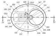
도 3은 본 개시내용의 일 실시예에 따라 조립된 도 2의 카테터의 원위 부분의 단부도이다.
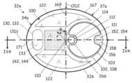
도 3a는 본 개시내용의 일 실시예에 따라 조립된 도 2의 카테터의 다른 원위 부분의 단부도이다.
도 4는 본 개시내용의 일 실시예에 따른 도 3의 평면 IV-IV에서의 카테터의 원위 부분의 부분 단면도이다.
도 4a는 본 개시내용의 일 실시예에 따른 도3a의 평면 IVA-IVA에서의 카테터의 원위 부분의 부분 단면도이다.
도 5는 본 개시내용의 일 실시예에 따라 중립 배향의 도 2의 카테터의 원위 부분의 입면도이다.
도 6은 본 개시내용의 일 실시예에 따른 완전히 붕괴된 구성에 있는 도 5의 원위 부분의 입면도이다.
도 7은 본 개시내용의 일 실시예에 따라 완전 팽창 구성에 있는 도 5의 원위 부분의 입면도이다.1 is a schematic diagram of an endoscopic system for laser lithotripsy according to one embodiment of the present disclosure.
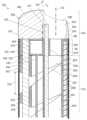
2 is a partially exploded perspective view of the distal portion of a catheter with a steering section according to one embodiment of the present disclosure.
Figure 3 is an end view of the distal portion of the catheter of Figure 2 assembled in accordance with one embodiment of the present disclosure.
FIG. 3A is an end view of another distal portion of the catheter of FIG. 2 assembled in accordance with one embodiment of the present disclosure.
FIG. 4 is a partial cross-sectional view of the distal portion of the catheter in plane IV-IV of FIG. 3 according to one embodiment of the present disclosure.
FIG. 4A is a partial cross-sectional view of the distal portion of the catheter in plane IVA-IVA of FIG. 3A according to one embodiment of the present disclosure.
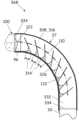
FIG. 5 is an elevational view of the distal portion of the catheter of FIG. 2 in a neutral orientation according to one embodiment of the present disclosure.
Figure 6 is an elevation view of the distal portion of Figure 5 in a fully collapsed configuration according to one embodiment of the present disclosure.
Figure 7 is an elevation view of the distal portion of Figure 5 in a fully expanded configuration according to one embodiment of the present disclosure.
도 1을 참조하면, 레이저 쇄석술을 위한 내시경 시스템이 본 개시내용의 일 실시예에 따라 개략적으로 도시되어 있다. 내시경 시스템(30)은, 손잡이(38)에 결합된 근단(36)을 갖는 카테터(32), 및 원위 헤드 부분(34)과 조향 섹션(37)을 포함하는 원위 부분(35)을 포함한다. 카테터(32)는 가요성(도시됨)일 수 있는 카테터 샤프트(33)를 포함한다. 손잡이(38)는 원위 헤드 부분(34)에 결합된 조향 메커니즘(39)을 수용할 수 있다. 손잡이(38)는 카테터(32)를 통한 원위 헤드 부분(34)에 대한 제어 및 전달을 위해 다양한 외부 구성요소 또는 시스템(40)을 통합한다. 외부 시스템(40)은 관주 시스템(42), 흡입 또는 흡인 시스템(44), 절제 레이저 시스템(46), 조명 시스템(52) 및 시각화 시스템(54)을 포함할 수 있다. 내시경 시스템(30)의 구성요소 중 일부는 손잡이(38), 카테터(32) 또는 원위 헤드 부분(34)에 부분적으로 또는 완전히 통합될 수 있다. 예를 들어 손잡이(38)는, 흡인 및 관주 시스템(42, 44)의 제어 메커니즘, 및 레이저 섬유의 원위 단부 및 다른 구성요소들의 위치를 조정하기 위한 메커니즘을 포함할 수 있다. 섬유 위치설정 메커니즘은, 레이저 섬유의 원위 말단이 원하는 위치에 위치되고 나서 결합될 수 있는 클램프(미도시)를 포함할 수도 있다. 레이저 섬유를 클램핑하는 것은 통상적으로 0.05 내지 0.1 밀리미터 범위의 정확도로 원위 말단의 위치를 고정한다. 중심축(110)을 따른 카테터 샤프트(33)로부터 원위 헤드 부분(34)으로의 방향은 본 명세서에서 원위 방향(50)이라 칭한다. 원위 방향(50)에 대향하는 방향은 본 명세서에서 근위 방향(51)이라 칭한다.1, an endoscopic system for laser lithotripsy is schematically depicted in accordance with one embodiment of the present disclosure. The
기능적으로, 조향 메커니즘(39)은, 환자의 신체 맥관을 통해 목표 구역(56)으로 라우팅하기 위해 그리고 목표 구역(56) 내의 개별적인 신체 결석(58)에 맞춰 원위 헤드 부분(34)의 정렬이 행해지도록, 카테터(32)의 원위 부분(35)에서의 조향 섹션(37)의 관절운동을 가능하게 한다. 조향 섹션(37)은 카테터(32)의 원위 부분(35)이 과도한 응력, 변형 및 왜곡이 없이 굴절하는 것을 가능케 한다. 조명 시스템(52)은, 신체 결석(58) 및 주변 조직, 예를 들어 신장, 요관 또는 방광 내의 결석을 조명하기 위해 목표 구역(56)으로 전달되는 가시광선을 발생시킨다. 예를 들어 절제 레이저 시스템(46)은, 신체 결석(58)의 절제 및 파괴를 위해 레이저 에너지를 목표 구역(56)으로 전달하기 위한, 툴륨 또는 홀뮴 섬유 또는 고체 상태 레이저를 포함한다. 레이저 에너지의 전달은 레이저 섬유, 예를 들어 실리카 또는 기타 광섬유 재료를 사용하여 달성될 수 있다. 관주 시스템(42)은, 목표 구역(56)의 냉각을 위해 그리고 목표 구역(56) 내에서 신체 결석(58)의 조각을 이동시키기 위해, 가압된 관주 유체를 제공한다. 흡인 시스템(44)은, 매체 내에 부유될 수 있는 신체 결석(58)의 입자를 비롯하여, 액체 매체를 목표 구역(56)으로부터 멀어지게 당긴다. 일부 실시예에서, 흡인 시스템(44)은 흡인 압력을 모니터링하는 압력 센서(48)를 포함한다. 압력 센서는 또한 관주 압력을 모니터하도록 사용될 수 있다.Functionally, the
여기서, "신체 결석"은, 신장 결석 및 요관 결석을 비롯하여, 인체에 의해 생성되는 모든 결석과, 칼슘 결석, 요산 결석, 스트루바이트(struvite) 결석 및 시스테인(cysteine) 결석을 포함하는 이들의 종류를 포괄한다. "신체 결석"은 또한 신체의 다른 장기 내에서 발견되거나 또는 그에 의해 형성되는 결석, 예를 들어, 방광 결석, 담낭 결석, 전립선 결석, 췌장 결석, 타액선 결석 및 복부 결석을 포함할 수 있다. 본 개시내용은 신장 결석 및 요관 결석의 분쇄를 위한 시스템 및 기술을 설명하지만, 대체로 이에 제한되지는 않는다. 본 개시내용의 관점에서, 신체 결석 치료 분야의 통상의 기술자는, 경조직 및 연조직의 치료를 위해서뿐만 아니라 신장 결석 및 요관 결석 이외의 신체 결석의 치료를 위한 본 명세서에 개시된 다양한 측면의 적용을 인식할 것이다.Here, “body stones” refers to all stones produced by the human body, including kidney stones and ureter stones, and their types, including calcium stones, uric acid stones, struvite stones and cysteine stones. encompasses. “Body stones” may also include stones found within or formed by other organs of the body, such as bladder stones, gallbladder stones, prostate stones, pancreatic stones, salivary gland stones, and abdominal stones. The present disclosure describes systems and techniques for comminution of kidney stones and ureteral stones, but is generally not limited thereto. In view of this disclosure, one skilled in the art of treating body stones will recognize the application of the various aspects disclosed herein for the treatment of body stones other than kidney stones and ureteral stones, as well as for the treatment of hard and soft tissues. will be.
도 2, 도 3 및 도 4를 참조하면, 카테터(32)의 원위 부분(35)에서의 조향 섹션(37)이 본 개시내용의 일 실시예에 따라 도시되어 있다. 일부 실시예에서, 조향 섹션(37)은 조향 섹션(37)의 근위 부분(303)으로부터 원위 단부 부분(305)까지를 형성하고 그에 걸쳐 연장하는 복수의 세그먼트(304)를 포함한다. 여기서, 조향 섹션(37)의 근위 부분(303)은 후술되는 복수의 갭(312)의 최근위부의 근위에서 그에 인접한 카테터(32)의 영역이다.2, 3 and 4, a
복수의 세그먼트(304)는 카테터 샤프트(33)의 제1 측방향 측면(306)에서 분리되고 제2 측방향 측면(308)에서 서로 결합될 수 있다. 복수의 세그먼트(304)의 분리는 복수의 세그먼트(304) 사이에 복수의 갭(312)을 형성하고, 복수의 갭(312) 각각은 제1 측방향 측면(306) 상에 최대 갭 치수(314)를 형성한다. 복수의 세그먼트(304)가 결합되는 제2 측방향 측면(308)은, 조향 섹션(37)의 스파인(316)을 특징으로 할 수 있다. 일부 실시예에서, 스파인(316)은 갭(312)(도시됨)의 최대 갭 치수(314)에 정반대쪽에 있다. 일부 실시예에서, 조향 섹션(37)은 작업 채널(102, 124)을 형성한다. 작업 채널(124)은 분할을 제공하기 위해 복수의 갭(312)을 형성하도록 천공될 수 있다. 복수의 세그먼트(304)가 작업 채널(102) 주위에 형성되지만, 조향 섹션(37)을 통한 연속적인 통로로서의 작업 채널(102)의 무결성을 보존하기 위해,작업 채널(102)을 파괴하지 않을 수 있다.The plurality of
일부 실시예에서, 복수의 세그먼트(304) 각각은, 카테터 샤프트(33)의 제1 측방향 측면(306)에 근접한 복수의 안내 통로 세그먼트(322)(복수의 세그먼트(304) 각각에 대해 하나의 안내 통로 세그먼트)를 형성한다. 복수의 안내 통로(322)는 안내 축(324)을 형성할 수 있고 안내 축(324)에 대해 동심일 수 있다. 단면(133)을 형성하는 조명 광섬유(132)는 복수의 안내 통로(322)를 통과하여 조명 광섬유 포트(134) 내로 이동한다. 조명 광섬유 포트(134)는 원위 헤드 부분(34)(도시됨)의 베이스(96)에 형성될 수 있다. 대안적으로, 조명 광섬유 포트는 조향 섹션(37)의 원위 단부 부분(305)에 형성될 수 있다.In some embodiments, each of the plurality of
도시된 실시예에서, 안내 통로(322)는 광섬유(132) 또는 장방형 단면의 광섬유 다발을 수용하기 위해 장방형 형상이다. 안내 통로 및 다른 기하학적 형상(예를 들어, 원형)의 광섬유 단면이 또한 이용될 수도 있다. 조명 광섬유(132) 및 복수의 안내 통로(322) 각각은 서로에 대해 긴밀한 활주 끼워맞춤을 위해 치수설정될 수 있다. 여기서, "긴밀한 활주 끼워맞춤"은 주목할만한 유격 없이 구성요소들 사이의 활주를 가능하게 하는 끼워맞춤으로서 이해된다.In the depicted embodiment,
일부 실시예에서, 조향 섹션(37)은 조향 섹션(37)의 외부 표면(328) 위로 연장하는 슬리브(326)(도 2에 가상선으로 도시됨)에 의해 둘러싸여 있다. 슬리브(326)는 원위 헤드 부분(34)의 원위 베이스(96)에 고정될 수도 있고, 또한 조향 섹션(37)의 근위 부분(303)에 고정될 수도 있다. 슬리브(326)의 고정은 조향 섹션의 외부 표면(328)과 슬리브(326) 사이에 액체가 스며드는 것을 방지하는 밀봉 영역(334)을 제공할 수 있다. 일부 실시예에서, 카테터 샤프트(33)는 조향 섹션(37)의 근위 부분(303)으로부터 카테터(32)의 근단(36)을 통해 연장하는 안내 루멘(336)을 형성한다. 안내 루멘(336)은 안내 축(324)과 실질적으로 정렬될 수 있다.In some embodiments, the
슬리브(326)는 고탄성 멤브레인 재료로부터 제조될 수도 있어, 굴곡될 때 슬리브(326)가 조향 섹션(37)의 아치형 형상에 합치하는 것을 가능하게 한다. 예로는 대략 0.145 GPa의 탄성 계수를 갖는 PEBAX®와 같은 열가소성 탄성 중합체를 포함한다. 일부 실시예에서, 슬리브(326)의 두께는 50 내지 100μm 범위(경계값 포함)이다. 조립 시에, 슬리브(376)는 소정 길이로 절단되고, 조향 섹션(37) 위로 활주되고, 온도(예컨대, 80°C 내지 120°C)까지 가열된다.The
원위 헤드 부분(34)은 베이스(96)를 포함할 수 있다. 베이스(96)는 또한 조향 섹션(97)의 원위 팁 또는 종단부로서 특징지어질 수 있다. 일부 실시예에서, 베이스(96)는 도 2 및 도 4에 도시된 바와 같이 카테터 샤프트(33)로부터 분리되어 형성되고 거기에 부착된다. 다른 실시예에서, 베이스(96)는 카테터 샤프트(33)(미도시)와 단일체이다. 일부 실시예에서, 투명 캡 부분(100)이 베이스(96)의 원위면(98)에 고정된다. 투명 캡 부분(100)은 근위면(104) 및 원위면(106)을 포함한다. 투명 캡 부분(100)은 가시광선을 투과시키는 데 적절한 재료로 제조되고, 절제 레이저 시스템(46)의 동작 파장에서 낮은 흡수율 및 높은 손상 임계치를 포함할 수 있다. 투명 캡(100)을 위한 비제한적인 예시적 재료는 사파이어, 석영, 광학 세라믹, 및 무기 또는 유기 유리를 포함한다. 일부 실시예에서, 액체 매체(실질적으로 물)의 굴절률과 대략적으로 합치되도록, 투명 캡(100)의 굴절률은 약 1.31 내지 1.35이다. 일부 실시예에서, 베이스(96)는 투명 캡(100)과 동일한 투명 재료로 제조될 수 있다.
일부 실시예에서, 원위 헤드 부분(34)은 조명기(130)를 포함한다. 조명기(130)는, 가시 스펙트럼의 광을 전달하기 위한 조명 또는 도광(lighting) 광섬유(132)(도시됨) 또는 광섬유 다발(미도시)의 원위 단부일 수 있다. 조명기(130)는 손잡이(38)에서 조명 시스템(52)에 동작적으로 결합된다. 여기서, 조명기(130)는 단일 광섬유(132)로 표현되지만, 단일 광섬유 다발이 단일 광섬유(132) 대신에 사용될 수 있음이 이해된다. 조명 광섬유(132)는 원위 헤드 부분(34)의 베이스(96)에 형성된 조명 광섬유 포트(134)를 통과하고, 투명 캡(100) 내로 연장될 수 있다. 조명 광섬유(132)는 광학 도파관으로서 작용한다.In some embodiments,
일부 실시예에서, 조명 광섬유(132)는 원위 헤드 부분(34)에, 예를 들어 조명 광섬유 포트(134) 또는 투명 캡(100) 또는 양자 모두에 기계적으로(예를 들어, 접착제를 사용하여) 부착된다. 이에 의해 원위 헤드 부분(34)은 조명 광섬유(들)(132)를 통해 손잡이(38)의 조향 메커니즘(39)에 결합된다. 이렇게 배열된 조명 광섬유(132)의 결합 및 라우팅은, 조명 광섬유(들)(132)가 또한 원위 헤드 부분(34)의 조향을 위한 견인 링키지(pulling linkage) 또는 추진-견인 링키지(push-pull linkage)로서 기능할 수 있게 하여, 이에 의해 별도의 견인 와이어 및 이들을 원위 헤드 부분(34)에 결합하는 것과 관련된 커넥터에 대한 필요성을 없앤다.In some embodiments, the illuminating
원위 헤드 부분(34)은, 원위 헤드 부분(34)의 베이스(96)를 통과하고 투명 캡 부분(100)의 근위면(104) 및 원위면(106)을 통과하는 작업 채널(102)을 형성한다. 작업 채널(102)은 원위면(106)에 입구부(108)를 형성하며, 입구부(108)는 작업 포트 축(111) 주위에 동심이다. 여기서, "작업 채널"은 관주 채널, 흡인 채널 또는 양자 모두로서 기능할 수 있다. 본 명세서에 사용되는 작업 채널은 레이저 섬유 및 바스켓과 같은 작업 물체를 수용하도록 선택적으로 구성될 수 있다. 작업 포트(103)의 내경은 0.05mm 코어 레이저 섬유를 이용하는 가요성 카테터에 대해 0.5 내지 1.5mm 범위(경계값 포함)일 수 있다. 일 예에서, 작업 채널(102)은 흡인 포트로서 기능하며, 이 경우 입구부(108) 및 작업 채널은 흡인 입구를 형성한다. 작업 채널(102)은 카테터(32)를 통해 연장되고, 예를 들어 손잡이(38)에서 흡인 시스템(44)에 결합될 수 있다. 작업 채널(102)은, 원위 헤드 부분(34)에 형성되어 이를 통과하며 입구부(108)를 형성하는 작업 포트(103)를 포함한다.The
일부 실시예에서, 원위 헤드 부분(34)은 장축(171) 및 단축(169)과 대응하는 외부 치수(OD1, OD2)를 갖는 장방형 단면(167)(도시됨)을 형성한다. 여기서, "장방형" 단면은 서로 수직이고 중심축(110)에서 교차하는 주 치수(OD1) 및 부 치수(OD2)를 갖는다. 주 치수(OD1)는 중심축(110)을 통과하는 장방형 단면(167)의 최대 치수이다. 부 치수(OD2)는 중심축(110)에서 주 치수(OD1)에 수직하고 주 치수(OD1)보다 작은 치수이다. 부 치수(OD2)는 단면(167)의 최소 치수일 수 있지만 반드시 그럴 필요는 없다. 일부 실시예에서, 장방형 단면(167)의 외부 치수(OD1)는 1.7 내지 3.2mm의 범위(경계값 포함)에 있으며, 일부 실시예에서, 외부 치수(OD1)는 1.7mm 내지 2.6mm의 범위(경계값 포함)에 있고, 일부 실시예에서, 외부 치수(OD1)는 2.2 내지 2.5mm의 범위(경계값 포함)에 있다. 일부 실시예에서, 단면(167)의 외부 치수(OD2)는 1.7 내지 2.5 밀리미터의 범위(경계값 포함)이고, 일부 실시예에서, 외부 치수(OD2)는 1.7 내지 2.0 밀리미터의 범위이다.In some embodiments, the
일부 실시예에서, 원위 헤드 부분(34)은 중심축(110)을 형성하고 중심축에 대해 동심인 원형 단면(미도시)을 포함하고, 원형 단면은 약 2mm의 직경을 갖는다. 일부 실시예에서, 최대 직경은 1.5 내지 3 밀리미터의 범위(경계값 포함)이고; 일부 실시예에서, 최대 직경은 1.8 내지 2.5 밀리미터의 범위(경계값 포함)이고; 일부 실시예에서, 최대 직경은 2 내지 2.5 밀리미터의 범위(경계값 포함)이다.In some embodiments, the
절제 레이저 에너지를 전달하기 위한 레이저 광섬유(112)가 작업 채널(102) 내에 배치되고, 레이저 광섬유(112)의 원위 말단(114)은 투명 캡 부분(100)의 원위면(106)에 근접하게 위치되며, 레이저 광섬유(112)의 근위 단부는 손잡이(38)를 통해 절제 레이저 시스템(46)에 결합된다. 레이저 광섬유(112)의 코어 직경은 가요성 샤프트를 갖는 카테터에 대해 0.05 내지 0.4 밀리미터의 범위일 수 있다. 일부 실시예에서, 레이저 광섬유(112)의 원위 말단(114)의 위치는, 예를 들어 투명 캡 부분(100)의 원위면(106)에 대해 +/- 5mm 범위(경계값 포함) 내에서 제어될 수 있으며, 여기서 "+" 및 "-"는 각각 작업 포트 축(111)을 따르는 원위 및 근위 방향을 지칭한다.A laser
일부 실시예에서, 원위 헤드 부분(34)은 내시경 시스템(30)을 위한 시야를 형성하는 이미지 형성 광학장치를 포함할 수 있는 이미징 수신기(142)를 포함한다. 이미징 수신기(142)는 상보형 금속 산화물 반도체(CMOS) 센서(반도체 칩, 이미징 광학장치, 및 지원 전자기기를 포함) 또는 전하 결합 소자(CCD) 카메라 센서와 같은 이미징 장치(144)(도시됨)일 수 있다. 일부 실시예에서, 이미징 수신기(142)의 이미징 면은 0.5x0.5mm 내지 1.5x1.5mm이다. 설명된 CMOS 이미지 센서의 예는 스위스 아르가우 소재의 AWAIBA CMOS 이미지 센서에 의해 공급되는 NANEYE 2D이다. https://ams.com/naneye(2020년 1월 16일 마지막 방문)를 참조한다.In some embodiments,
이미징 장치(144)는, 카테터(32)를 통해 연장하며 손잡이(38)에서 시각화 시스템(54)에 결합될 수 있는 케이블(146)을 포함할 수 있다. 케이블(146)은 원위 헤드 부분(34)의 베이스(96)에 의해 형성된 케이블 포트(145)를 통해 라우팅될 수 있다. 일부 실시예에서, 이미징 장치(144)는 베이스(96)의 원위면(98)에서 리세스(147) 내에 배치된다. 이미징 장치(144)는 법선에 대해 ±45도인 시야각을 형성할 수 있다. 선택적으로, 이미징 수신기(142)는, 카테터(32)를 통해 연장하며 손잡이(38)에서 시각화 시스템(54)에 결합되는 이미징 광섬유(미도시), 그리고, 광학 시스템의 원위 단부이다. 투명 캡(100)의 원위면(106)은 평평하거나, 둥글거나(도시됨) 또는, 대안적으로, 이미징 수신기(142) 상으로의 이미징을 위한 렌즈로서 성형될 수 있다.Imaging device 144 may include a
도 3a 및 도 4a를 참조하면, 대안적인 원위 헤드 부분(34a) 및 대안적인 조향 섹션(37a)을 갖는 카테터(32a)가 본 개시내용의 실시예에 따라 도시되어 있다. 카테터(32a)는, 도 3a 및 도 4a에 동일 표시 참조 문자로 도시된 카테터(32)와 동일한 구성요소 및 속성의 일부 또는 전부를 포함할 수 있다. 조향 섹션(37a)은, 작업 포트 축(111)에 실질적으로 평행하게 작업 포트(103)를 따라서 연장하는 탄성 스파인 부재(152)를 포함한다. 일부 실시예에서, 탄성 스파인 부재(152)는 조향 섹션(37a)의 스파인(316) 내에 매립된다. 대안적으로 또는 추가적으로, 탄성 스파인 부재(152)의 원위 단부(154)는 카테터(32)의 베이스(96) 상에 포함된 마운트(156)에서 종결될 수 있다. 일부 실시예에서, 마운트(156)는 탄성 스파인 부재(152)를 수용하기 위한 루멘 또는 소켓(156)을 형성한다. 탄성 스파인 부재(152)는, 예를 들어 접착제를 사용하여, 원위 헤드 부분(34)의 베이스(96)에 고정될 수 있다. 일부 실시예에서, 탄성 스파인 부재(152)는 원위 헤드 부분(34)의 베이스(96)로부터 또는 달리 원위 단부 부분(305)에 근접한 위치로부터 조향 섹션(37a)의 근위 부분(303)까지 연장된다.3A and 4A, a
도 5 내지 도 7을 참고하면, 조향 섹션(37)의 동작이 본 개시내용의 실시예에 따라 도시되어 있다. 일부 실시예에서, 조향 섹션(37)은 양측방향으로 편향될 수 있다. 여기서, "양측방향(bilateral)" 및 그 파생 용어는, 도 5 내지 도 7에 도시된 바와 같이 중심축(110)에 대해 2개의 상이한 측방향(362, 364)으로의 편향을 지칭한다. 이들 도면은 중립 배향(366)(도 5), 완전 접힘 배향(368)(도 6) 및 완전 팽창 배향(370)(도 7)의 조향 섹션(37)을 도시한다. "중립(neutral)" 배향은 조향 메커니즘(39)을 통해 손잡이(38)에 의해 조향 섹션(37)에 가해지는 힘이 없을 때의 카테터(32)의 상태를 지칭한다. "완전 접힘(fully collapsed)" 배향(368)은 복수의 세그먼트(304) 사이의 복수의 갭(312)이, 예를 들어 조향 메커니즘(39)의 견인 스트로크 한계까지 또는 복수의 세그먼트(304)를 서로 맞닿아 접촉하도록 당김으로써, 최대 범위로 함께 견인될 때 실행된다. "완전 팽창(fully expanded)" 배향(370)은, 복수의 세그먼트(304) 사이의 복수의 갭(312)이 예를 들어 조향 메커니즘(39)의 추진 스트로크 한계까지 최대 범위로 분리될 때 실행된다. 측방향들(362, 364)은 반대일 수 있다(도시됨). 일부 실시예에서, 조향 섹션(37)은, 완전 접힘 배향(368)으로부터 완전 팽창 배향(370)까지 180도까지의 총 각도 편향 범위를 위해, 중립 배향(366)으로부터 어느 하나의 측방향(362, 364)으로 90도만큼 중심축(110)을 편향시킨다. 일부 실시예에서, 총 각도 편향 범위는 270도까지이다.5-7, the operation of
기능적으로, 카테터 샤프트(33)의 조향 섹션(37)은 단일 조명 광섬유(132)를 사용하여 중립 배향(366)에 대한 양측방향 편향을 가능하게 할 수 있다. 선택적으로, 단일 광섬유(132) 대신에 단일 광섬유 다발(미도시)이 구현될 수 있다. 단일 조명 광섬유(132)가 인장 상태가 될 때(즉, 카테터 샤프트(33)를 통해 "견인될 때”), 단일 조명 광섬유(132)가 고정되는 원위 헤드 부분(34)은 조향 섹션(37)의 근위 부분(303)을 향해 근위 방향으로 당겨진다. 제1 측방향 측면(306)을 따른 조향 섹션(37)의 복수의 세그먼트(304)는, 중립 배향(366)의 최대 갭 치수(314)에 비해 감소된 복수의 갭(312)(도 6)의 최대 갭 치수(314')를 형성하도록 함께 당겨진다. 한편, 조향 섹션(37)의 스파인(316)을 형성하는 복수의 세그먼트(304)의 부분은 실질적으로 동일한 치수를 유지한다. 그 효과는, 조향 섹션(37)이 중립 배향(366)에 대해 제1 측방향(362)으로 원호를 형성하게 하는 것이다. 단일 조명 광섬유(132)가 압축될 때(즉, 카테터 샤프트(33)를 통해 "추진될 때”), 원위 헤드 부분(34)은 조향 섹션(37)의 근위 부분(303)으로부터 멀리 원위 방향으로 추진되어, 제1 측방향 측면(306)을 따른 조향 섹션(37)의 복수의 세그먼트(304)는, 중립 배향(366)의 최대 갭 치수(314)에 비해 증가된 복수의 갭(312)(도 7)의 최대 갭 치수(314")를 형성하도록 추가로 분리된다. 한편, 조향 섹션(37)의 스파인(316)을 형성하는 복수의 세그먼트(304)의 부분은 역시 실질적으로 동일한 치수를 유지한다. 그 효과는, 조향 섹션(37)이 중립 배향(366)에 대해 제2 측방향(364)으로 원호를 형성하게 하는 것이다. 견인 및 추진 동작 동안, 단일 조명 광섬유(132)와 복수의 안내 통로(322) 사이의 긴밀한 활주 끼워맞춤은, 세그먼트(304)가 중심축(110)을 따라 재배향될 때 복수의 세그먼트(304)가 단일 조명 광섬유(132)를 따라 재배치될 수 있게 한다.Functionally, the
복수의 세그먼트(304)를 통해 단일 조명 광섬유(132)를 라우팅하는 것은 또한, 도 7의 추진 동작 동안 직면하는 압축력으로 인한 단일 조명 광섬유(132)의 칼럼 좌굴(column buckling)을 방지한다. 추진 동작 중에, 단일 조명 광섬유(132)에 가해지는 압축력은, 예를 들어 슬리브(326)의 신장(stretching), 스파인(316)의 굴곡, 및 환자의 체강에 대한 활주 또는 마찰 저항에 의해 초래된다. 칼럼 좌굴을 유발하는데 필요한 소위 "임계력"은, 칼럼의 단면 관성 모멘트 및 탄성 계수에 비례할 뿐만 아니라, 칼럼의 길이에 반비례한다. 예를 들어, 문헌 Budynas, "Advanced Strength and Applied Stress Analysis," pp. 92-96, McGraw-Hill ⓒ 1977을 참조하길 바라며, 이 문헌의 개시내용은 그에 포함된 명백한 정의를 제외하고는 여기에 참고로 포함된다. 조향 섹션(37) 및 조명 광섬유(132)에 대해, 칼럼 길이는 복수의 세그먼트(304)(도 7)의 인접한 세그먼트들 사이에서 단일 조명 광섬유(132)의 최대 지지되지 않은 길이(372)에 의해 근사될 수 있다. 지지되지 않은 길이가 최대일 때 칼럼 좌굴에 필요한 임계력이 최소이기 때문에, 칼럼 좌굴을 방지하기 위한 관심 구성은 지지되지 않은 길이(372)가 가장 긴 완전 팽창 배향(370)이다. 최대 지지되지 않은 길이(372)는 완전 팽창 배향(370)에서의 최대 갭 치수(314")에 대략적으로 대응할 수 있다. 따라서, 조향 섹션(37)은 완전 팽창 구성(370)에서 단일 조명 광섬유(132)의 칼럼 좌굴을 방지하도록 설계될 수 있다.Routing the single illumination
일부 실시예에서, 조향 섹션(37)의 다양한 구성요소의 탄성은, 조향 섹션(37)의 중립 배향(366)으로의 자동 복귀를 위해 원위 단부 조향 섹션(37)을 측방향으로 편향시키기에 충분한 탄성을 제공한다. 이러한 구성요소는, 레이저 광섬유(112), 원위 단부 조향 섹션(37)을 둘러싸는 슬리브(326), 원위 단부 조향 섹션(37)의 스파인(316), 및/또는 조명 광섬유(132) 자체를, 단독으로 또는 조합하여 포함할 수 있다. 보조 편향 부재(152)를 구현하는 실시예에서, 원위 단부 조향 섹션(37a)의 중립 배향(366)으로의 자동 복귀가 부가적인 측방향 편향에 의해서 향상된다. 이러한 실시예에서, 중립 배향(366)으로의 복귀는 중립 배향(366)을 실행하는 데 광섬유(132) 추진을 거의 또는 전혀 요구하지 않을 수 있다.In some embodiments, the elasticity of the various components of the
원위 단부 조향 섹션(37, 37a)의 자동 또는 근사 자동 복귀는 카테터(32, 32a)의 단방향 조향을 가능하게 한다. 단방향 조향은 중립 배향(366)(도 5) 및 완전 접힘 배향(368)(도 6)뿐만 아니라 그 사이에 형성된 배향을 특징으로 한다. 중립 배향(366)으로의 복귀는 광섬유(132)에 의한 원위 단부 조향 섹션(37) 추진에 의존하지 않기 때문에, 광섬유(132)의 좌굴에 관한 우려가 감소되고, 광섬유(132)의 단면(133)이 감소될 수 있다. 단면(133)의 감소는 원위 헤드 부분(34)의 단면(167) 내의 공간을 확보하며, 따라서 다른 구성요소(예를 들어, 더 큰 관주 채널(122))를 위한 또는 단면(167)의 전체 영역의 감소를 위한 더 많은 공간을 제공한다.Automatic or near-automatic retraction of the distal
도 2 내지 도 7의 실시예에서, 조명 광섬유(132)가 조향 섹션(37)의 양측방향 편향을 구동하는 것으로 도시되고 설명된다. 또한, 도 2 내지 도 7의 실시예는, 작업 채널(124)(예를 들어, 관주 제공)이 복수의 갭(312)에 의해 천공되고 슬리브(326)와 유체 연통되는 반면, 작업 채널(102)의 무결성을 보존하는 것으로서(예를 들어, 흡인 제공) 도시되고 설명된다. 이들 기능은 내시경 시스템(30)의 다른 구성요소에 의해 수행될 수 있다. 예를 들어, 레이저 광섬유 루멘(266) 및 레이저 광섬유(112)가 베이스(96)의 외부 표면에 근접하게(즉, 중심축(110)으로부터의 거리가 증가된 상태로) 작업 채널(102) 내에 배치되는 것이 고려된다. 이러한 구성에서, 레이저 광섬유(112) 및 단일 조명 광섬유(132)는 카테터(32)를 조향하기 위한 추진-견인 링키지로서 동작할 수 있다. 또한, 복수의 세그먼트(304)가 관주 채널(122)의 무결성을 보존하도록 구성되고, 작업 채널(102)이 천공 및 슬리브(326)에 의해 수납되는, 구성이 고려된다. 이러한 수정은 본 개시내용에 제시된 원리에 기초한 통상의 기술자가 이해할 수 있는 범위 내에 있다.2-7, the illumination
본 명세서에서 개시된 부가적인 도면 및 방법 각각은, 동일한 것을 만들고 사용하기 위한 개선된 장치 및 방법을 제공하기 위해, 별개로 또는 다른 특징 및 방법과 함께 이용될 수 있다. 따라서, 본 명세서에 개시된 특징 및 방법의 조합은, 본 개시내용을 그 가장 넓은 의미로 실시하는데 필요하지 않을 수 있으며, 대신에 단지 대표적이고 바람직한 실시예를 특히 설명하기 위해 개시된 것이다.Each of the additional figures and methods disclosed herein may be used separately or in conjunction with other features and methods to provide improved devices and methods for making and using the same. Accordingly, combinations of features and methods disclosed herein may not be necessary to practice the disclosure in its broadest sense, and are instead disclosed merely to specifically illustrate representative and preferred embodiments.
실시예에 대한 다양한 수정은 본 개시내용을 읽는 관련 기술분야의 통상의 기술자에게 명백할 수 있다. 예를 들어, 관련 기술분야의 통상의 기술자는, 상이한 실시예에 대해 설명된 다양한 특징들이 단독으로 또는 상이한 조합으로 다른 특징과 적절하게 조합되거나, 조합되지 않거나, 재조합될 수 있음을 인식할 것이다. 마찬가지로, 전술한 다양한 특징은 모두 본 개시내용의 범위 또는 사상에 대한 제한보다는 예시적인 실시예로 간주되어야 한다.Various modifications to the embodiments may be apparent to those skilled in the art upon reading this disclosure. For example, those skilled in the art will recognize that various features described for different embodiments may be appropriately combined, uncombined, or recombined with other features alone or in different combinations. Likewise, all of the various features described above should be regarded as illustrative examples rather than limitations on the scope or spirit of the disclosure.
관련 기술분야의 통상의 기술자는 다양한 실시예가 전술한 임의의 개별 실시예에서 예시된 것보다 적은 수의 특징을 포함할 수 있다는 것을 알 수 있을 것이다. 본 명세서에 설명된 실시예들은, 다양한 특징들이 조합될 수 있는 방식의 포괄적인 제시를 의미하지 않는다. 따라서, 실시예들은 특징들의 상호 배타적인 조합이 아니고, 오히려 관련 기술분야의 통상의 기술자에게 이해되는 바와 같이, 청구항은 상이한 개별적인 실시예로부터 선택된 상이한 개별적인 특징의 조합을 포함할 수 있다.Those skilled in the art will appreciate that various embodiments may include fewer features than those illustrated in any individual embodiment described above. The embodiments described herein are not meant to be a comprehensive presentation of the ways in which various features may be combined. Accordingly, the embodiments are not mutually exclusive combinations of features, but rather, as would be understood by those skilled in the art, the claims may include combinations of different individual features selected from different individual embodiments.
상기 문헌의 참조에 의한 임의의 통합은 어떠한 주제도 본 명세서의 명시적 개시내용에 반하는 것으로 통합되지 않도록 제한된다. 문헌 내에 포함된 어떠한 청구항도 본 명세서에서 참조로 포함되지 않도록, 전술한 문헌의 참조에 의한 임의의 통합이 추가적으로 제한된다. 본 명세서에서 명백하게 포함되지 않는 한, 문헌에 제공된 임의의 형성이 본 명세서에서 참조로 포함되지 않도록, 전술한 문헌의 참조에 의한 임의의 통합이 또한 추가적으로 제한된다.Any incorporation by reference of the above documents is limited so that no subject matter is incorporated contrary to the express disclosure herein. Any incorporation by reference of the foregoing documents is further limited such that no claim contained within the document is hereby incorporated by reference. Any incorporation by reference of the foregoing documents is also further limited such that any formation provided in the document is not incorporated herein by reference unless expressly incorporated herein.
달리 지시되지 않으면, 본 명세서에 포함된 "실시예(들)", "개시내용", "본 개시내용", "개시내용의 실시예(들)", "개시된 실시예(들)" 등에 대한 언급은 인정된 종래 기술이 아닌 본 특허 출원의 명세서(청구범위 및 도면을 포함하는, 텍스트)를 지칭한다.Unless otherwise indicated, reference to “embodiment(s)”, “disclosure”, “present disclosure”, “embodiment(s) of the disclosure”, “disclosed embodiment(s)”, etc. contained herein. References refer to the specification (text, including claims and drawings) of this patent application and not to the acknowledged prior art.
청구범위를 해석하기 위해, 특정 용어 "~를 위한 수단" 또는 "~를 위한 단계"가 각각의 청구범위에 언급되지 않으면, 35 U.S.C. 112(f)의 조치가 적용되지 않는 것이 명백히 의도된다.For purposes of interpreting the claims, unless the specific terms “means for” or “steps for” are recited in each claim, 35 U.S.C. It is expressly intended that the measures in 112(f) shall not apply.
Claims (20)
Translated fromKorean중심축을 따라 순차적으로 배열되는 복수의 세그먼트를 포함하는 조향 섹션으로서, 상기 복수의 세그먼트는 그 사이에 복수의 갭을 형성하도록 상기 조향 섹션의 제1 측방향 측면에서 분리되는, 조향 섹션; 및
상기 조향 섹션의 원위 단부 부분으로 연장하는 광섬유를 포함하고,
상기 광섬유를 인장 상태로 배치하는 것은 상기 조향 섹션을 제1 측방향으로 편향되게 하는 내시경 장치.It is an endoscope device,
a steering section comprising a plurality of segments arranged sequentially along a central axis, the plurality of segments being separated at a first lateral side of the steering section to form a plurality of gaps therebetween; and
comprising an optical fiber extending to a distal end portion of the steering section,
An endoscopic device wherein placing the optical fiber in tension biases the steering section in a first lateral direction.
상기 제1 측방향 측면은 상기 중심축으로부터 상기 제1 측방향에 있고,
상기 제2 측방향 측면은 상기 중심축으로부터 상기 제2 측방향에 있는, 내시경 장치.According to clause 19,
the first lateral side is in the first lateral direction from the central axis,
and the second lateral side is in the second lateral direction from the central axis.
Applications Claiming Priority (3)
| Application Number | Priority Date | Filing Date | Title |
|---|---|---|---|
| US202163242523P | 2021-09-10 | 2021-09-10 | |
| US63/242,523 | 2021-09-10 | ||
| PCT/US2022/043047WO2023039157A1 (en) | 2021-09-10 | 2022-09-09 | Flexible miniature endoscope |
Publications (1)
| Publication Number | Publication Date |
|---|---|
| KR20240052986Atrue KR20240052986A (en) | 2024-04-23 |
Family
ID=85507781
Family Applications (1)
| Application Number | Title | Priority Date | Filing Date |
|---|---|---|---|
| KR1020247011517APendingKR20240052986A (en) | 2021-09-10 | 2022-09-09 | flexible small endoscope |
Country Status (8)
| Country | Link |
|---|---|
| US (1) | US20240366065A1 (en) |
| EP (1) | EP4376692A4 (en) |
| JP (1) | JP2024532567A (en) |
| KR (1) | KR20240052986A (en) |
| CN (1) | CN117940055A (en) |
| CA (1) | CA3230560A1 (en) |
| MX (1) | MX2024003022A (en) |
| WO (1) | WO2023039157A1 (en) |
Family Cites Families (5)
| Publication number | Priority date | Publication date | Assignee | Title |
|---|---|---|---|---|
| US5807249A (en)* | 1996-02-16 | 1998-09-15 | Medtronic, Inc. | Reduced stiffness, bidirectionally deflecting catheter assembly |
| US8137336B2 (en)* | 2008-06-27 | 2012-03-20 | Boston Scientific Scimed, Inc. | Steerable medical device |
| HK1244652A1 (en)* | 2014-10-20 | 2018-08-17 | Research Development International Corporation | Steerable micro-endoscope |
| US11686043B2 (en)* | 2018-11-05 | 2023-06-27 | Acclarent, Inc. | Pull wire with coated fibers |
| US20230248434A1 (en)* | 2019-01-18 | 2023-08-10 | Ipg Photonics Corporation | Efficient multi-functional endoscopic instrument |
- 2022
- 2022-09-09KRKR1020247011517Apatent/KR20240052986A/enactivePending
- 2022-09-09CNCN202280060474.8Apatent/CN117940055A/enactivePending
- 2022-09-09WOPCT/US2022/043047patent/WO2023039157A1/ennot_activeCeased
- 2022-09-09MXMX2024003022Apatent/MX2024003022A/enunknown
- 2022-09-09USUS18/686,612patent/US20240366065A1/enactivePending
- 2022-09-09EPEP22868110.2Apatent/EP4376692A4/enactivePending
- 2022-09-09JPJP2024515479Apatent/JP2024532567A/enactivePending
- 2022-09-09CACA3230560Apatent/CA3230560A1/enactivePending
Also Published As
| Publication number | Publication date |
|---|---|
| WO2023039157A1 (en) | 2023-03-16 |
| US20240366065A1 (en) | 2024-11-07 |
| MX2024003022A (en) | 2024-03-26 |
| CN117940055A (en) | 2024-04-26 |
| EP4376692A4 (en) | 2025-07-02 |
| JP2024532567A (en) | 2024-09-05 |
| CA3230560A1 (en) | 2023-03-16 |
| EP4376692A1 (en) | 2024-06-05 |
Similar Documents
| Publication | Publication Date | Title |
|---|---|---|
| JP7520852B2 (en) | Efficient multifunctional endoscopic instruments | |
| US8075478B2 (en) | System, apparatus, and method for viewing a visually obscured portion of a cavity | |
| US5746770A (en) | Endoscopic retriever | |
| US20220053998A1 (en) | Devices, systems, and methods for treating kidney stones | |
| ES2881929T3 (en) | Ureteroscope for minimally invasive treatment of urinary stones | |
| US8657812B2 (en) | Side-firing laser fiber with internal bent fiber and related methods | |
| US4899733A (en) | Device and technique for transurethral ultrasonic lithotripsy using a flexible ureteroscope | |
| CN114040700A (en) | Devices, systems, and methods for treating kidney stones | |
| MX2011001098A (en) | Swing prism endoscope. | |
| CN112842525B (en) | An endoscopic laser ablation catheter | |
| CA2679487A1 (en) | Face tip assembly for an endoscope | |
| KR20130008556A (en) | Multi-fiber flexible surgical probe | |
| US20230130759A1 (en) | Embedded laser fiber for aspirated stone ablation | |
| US20220265350A1 (en) | Modular wireless large bore vacuum universal endoscope and vacuumscope | |
| KR20240052986A (en) | flexible small endoscope | |
| KR20250135785A (en) | Endoscopic aspiration method and device | |
| US20060089534A1 (en) | Medical instrument, in particular uretero-renoscope | |
| JP2018521749A (en) | Surgical instruments, especially ureteroscopes | |
| CN218572164U (en) | Novel negative pressure suction ureteroscope | |
| Georgescu et al. | Instruments | |
| Fernie et al. | Small core fiber coupled 60-W laser diode | |
| JPH02114930A (en) | Insertion assist jig for endoscope |
Legal Events
| Date | Code | Title | Description |
|---|---|---|---|
| PA0105 | International application | Patent event date:20240405 Patent event code:PA01051R01D Comment text:International Patent Application | |
| PG1501 | Laying open of application | ||
| A201 | Request for examination | ||
| PA0201 | Request for examination | Patent event code:PA02012R01D Patent event date:20250703 Comment text:Request for Examination of Application |